nasa technical note - pdas · / nasa technical note 4 m 4 z nasa _-- l5 ,i - tn d-2570 a numerical...
TRANSCRIPT
/ NASA TECHNICAL NOTE
4 m 4 z
N A S A _--
L5 ,I TN - D-2570
. ---
A NUMERICAL METHOD FOR CALCULATING THE FLAT-PLATE PRESSURE DISTRIBUTIONS ON SUPERSONIC WINGS OF ARBITRARY PLANFORM
by Wilbur D. Middleton und Hdrry W. Curlson
LungZey Reseurch Center LungZey Stution, Humpton, Vu.
NATIONAL AERONAUTICS AND SPACE ADMINISTRATION WASHINGTON, D. C. JANUARY 1 9 6 5
TECH LIBRARY KAFB, NM
A NUMERICAL METHOD FOR CALCULATING THE
FLAT-PLATE PRESSURE DISTRIBUTIONS ON SUPERSONIC WINGS
OF ARBITRARY PLANFORM
By Wilbur D. Middleton and Harry W. Car l son
Langley Resea rch Center Langley Station, Hampton, Va.
NATIONAL AERONAUTICS AND SPACE ADMINISTRATION
For sale by the Off ice of Technica l Services, Department of Commerce, Washington, D.C. 20230 -- Pr ice $1.00
A NUMERICAL METHOD FOR CALCULATING TKF:
FLAT-PLATE PRESSURE DISTRIBUTIONS ON SUPERSONIC WINGS
OF ARBITRARY PLANFORM
By Wilbur D. Middleton and Harry W. Carlson
SUMMARY
This reps& describes a numerical method based on l inear ized theory f o r calculat icg the f l a t - p l a t e l i f t ing-pressure d is t r ibu t ions on supersonic wings of a rb i t r a ry planform, and presents examples i l l u s t r a t i n g i t s usage. The precision of t he method i s shown by comparisons of pressure d is t r ibu t ions and force coef- f i c i e n t s calculated from the numerical method with those obtained from estab- l ished ana ly t ica l solutions f o r s t ra ight - l ine leading- and trail ing-edge wings. Several examples of the use of t he numerical method t o estimate the aerodynamic charac te r i s t ics of curved o r cranked leading-edge wings a re presented t o i l l u s - t r a t e t he f l e x i b i l i t y of the method.
INTROIXJCTION
A numerical method based on l i n e a r theory which allows the determination of camber surfaces corresponding t o specif ied load d is t r ibu t ions on supersonic wings of a rb i t r a ry planform ( r e s t r i c t e d only t o supersonic t r a i l i n g edges) has been presented i n reference 1. The method subs t i tu tes approximate summations f o r l inear-theory in t eg ra l equations and replaces the wing w i t h a mosaic of r ec t i l i nea r elements closely approximating the wing planform. These subst i tu- t ions allow great f l e x i b i l i t y i n defining both the planform shape and in t e rva l of integrat ion f o r a rb i t r a ry wing planforms. The speed of present-day d i g i t a l computers makes the solution p rac t i ca l .
An extension of t he numerical method of reference 1 allows the calculation of t he theore t ica l l i f t ing-pressure d is t r ibu t ions on f l a t wings of a rb i t r a ry planform ( r e s t r i c t e d t o supersonic t r a i l i n g edges). This report describes such a method and presents examples i l l u s t r a t i n g i t s use. The precision of the method i s shown by comparisons of pressure d is t r ibu t ions and force coeff ic ients calcu- l a t e d from the numerical method with those determined from established ana ly t ica l solutions f o r s t ra ight - l ine leading- and trail ing-edge wings.
The fur ther extension of t he numerical method t o the case of cambered wings i s indicated.

I "111 11111111 1111111 111111111 II
SYMBOLS
A; A(L,N) ; A(L*,N*)
PR aspect ratio, b2/S
b wing span
B; B(L*,p) trailing-edge grid-element length
C mean aerodynamic chord
c; c(L*,N*) grid-element width
CD drag coefficient
CL lift coefficient
leading-edge grid-element weighting factor
-
slope of lift curve per degree angle of attack CLa
Cm
CP
"in
pitching-moment coefficient about x = 0
pressure coefficient
lifting-pressure coefficient, Cp,lower - Cp,upper
average value of lifting-pressure coefficient over a grid element (see eq. (7))
smoothed value of lifting-pressure coefficient obtained from averaged coefficients (see eq. (8))
notch ratio
a constant (see figs. 16 and17)
overall length of wing, measured in streamwise direction
designation of influencing grid elements (see fig. 2)
designation of field-point grid elements (see fig. 2)
free-stream Mach number
value of N at right-hand wing tip
value of N at left-hand wing tip
2
influence function (see eq. ( 2 ) ) R
w
A
T
Subscripts:
L* ,N*
l e
t e
m
average value of influence function over a gr id element (see eq. ( 5 ) )
wing area
Cartesian coordinate system, X - a x i s streamwise
distance from wing apex t o center of pressure
apex spanwise posi t ion of M wing (see f i g . 14)
camber surface ordinate
wing angle of a t tack, deg
Tip chord Root chord
wing taper r a t i o ,
wing leading-edge sweepback angle
dummy variables of integrat ion for x and y, re spec t i ve l y
denotes a region of integrat ion bounded by wing planform and Mach forecone from point (x,y)
indicates value associated with element r o w (see eq. ( 1 4 ) )
value of a quantity along wing leading edge a t py = N
value of a quantity along wing t r a i l i n g edge a t py = N
corresponds t o case of two-dimensional wing
NUMERICAL CALCULATION METHOD
The numerical method f o r calculat ing the theore t ica l l i f t i n g pressure d is t r ibu t ions on supersonic wings employs a basic equation of l i nea r theory (eq. (77a) of ref. 2) which relates t h e l o c a l surface slope of a point on a l i f t i n g surface t o the pressure coeff ic ient a t t h e point, t h e influence of
3
I Illll 1l1llll1l
pressures upstream of t h e specif ied point being taken in to account. employed herein ac tua l ly i s an extension of the numerical method of reference 1, i n which t h e wing surface shape necessary t o support a specif ied l i f t d l s t r ibu t ion i s calculated.
The method
A typ ica l wing planform of a rb i t r a ry shape, defined by a rectangular Cartesian coordinate system, i s shown i n f igure 1. I n accordance with the concepts of l i nea r - ized theory, the wing i s assumed t o have negligible thickness and i s assumed t o l i e approximately i n the z = 0 plane. The wing surface i s f l a t and a t a slight incidence t o the l o c a l flow. The t r a i l i n g edge of t he wing i s supersonic.
BY. B 1
Figure 1.- Cartesian coordinate system.
Equation (2 ) of pressure coeff ic ient
Kp(X,Y) = -
reference 1 may be rearranged t o solve f o r the l i f t i n g - a t the f i e l d point (x,y) a s
where values of E p ( 5 , ~ ) E p ( x , y ) a s discussed subsequently. The region of integrat ion T extends over the wing planform within the Mach forecone from point (x ,y) , as shown by the
shaded region of f igure 1. The wing streamwise slope function -(x,y) i s a
constant f o r t he f l a t p l a t e a t incidence (s) and i s equal t o the tangent of
t he wing angle of a t tack .
i n the integrand a re previously determined values of
a Z C
dX
of equation (1) denotes t h a t only the gen-
e ra l ized pr inc ipa l pa r t (see r e f s . 2 and 3) of t he in t eg ra l i s of i n t e re s t , which permits an evaluation of the in t eg ra l across the s ingular i ty a t The numerical method subs t i tu tes a summation f o r t he in t eg ra l of equation (l), consisting of t he sum of an average pressure coeff ic ient times the in t eg ra l of t he R function over the gr id elements within T . The R function, which may be thought of a s an influence fac tor r e l a t ing the upstream pressures t o the l i f t i n g pressure a t point (x,y), i s defined as
s The special i n t eg ra l sign
y = 7.
4
- .. .. . ... . . I 111- 1111I I
I n in tegra t ing t h e R function over t h e individual elements, the i n t e g r a l i s regular except fo r t h e elements containing y = 7, which require t h e def ini- t i o n of t he generalized pr inc ipa l pa r t . The i n t e g r a l of t he R function f o r these elements i s more readi ly evaluated i f the q l i m i t s a re chosen as 7 - 6 and q + 6. With the g r id system oriented t o provide t h i s choice of limits, the in t eg ra l of t he R function over t he elements containing y = ‘1 becomes the de f in i t e i n t eg ra l of t h e function with t h e i n f i n i t e portion discarded. (See r e f . 2 or 3 . )
A s i n reference 1, the gr id system of t h e numerical method i s superimposed upon the wing planform as shown i n f igure 2, with gr id elements i den t i f i ed by L and N replacing t h e i n t e g r a l elements dg and dpq. Along the wing leading and t r a i l i n g edges, p a r t i a l g r i d elements are used t o improve t h e plan- form defini t ion. Values of L* and N* i den t i fy the g r id element associated with and immediately forward of t he f i e l d point (x,y). The gr id element L* i s numerically equal t o x and the gr id element i s numerically equal t o py, where x and py take on only integer values. The area of integrat ion of the numerical method consis ts of a group of g r id elements approximating T as shown by the shaded region of f igure 2. The gr id element system i l l u s t r a t e d i n f i g - ure 2 i s ra ther coarse; i n pract ice , many more elements a re employed.
Lx, L I 2 3 4 5 6 7 8 9 1 0
The numerical summation treats the integrat ion in t e rva l element by element, with the average l i f t i n g -
I , , I I I I I I I I 0 1 2 3 4 5 6 7 6 9 1 0
x , c
pressure coeff ic ient L Y l p ( ~ , ~ ) over Figure 2. - Grid system used in numerical t h e element being mult ipl ied by the average value of the influence function over t h& same g r id element. (L,N) t o t he l i f t ing-pressure coeff ic ient a t point (x,y) may be expressed by
solution. E,
The contribution of an individual element
1 rc ?~(L*-L,N*-N) A(L,N) E p ( ~ , ~ ) ( 3 )
The weighting f ac to r A(L,N) leading edges as follows:
accounts f o r f r ac t iona l elements along t h e wing
A(L,N) = o
5
where L l e i s numerically equal t o the whole number pa r t of the sum xle + 1,
or 1 + pie]. The bracket notation i s used t o s ignify tha t only the whole
number pa r t of the number i s retained.
Since it has been observed tha t an integrat ion of equation (2) i s rela- t i v e l y insensi t ive t o small var ia t ions i n E, the in t eg ra l of the function R over an individual element may be approximately evaluated with the value equal t o i t s average value sion f o r the average influence fac tor R is:
x - 5 The resul t ing expres- L* - L + 0.3. - (See r e f . 1.)
- -
d ( L * - L + 0 . 5 ) 2 - ( N * - N - 0 . 5 ) 2 ( ( L * - L + 0 . 5 ) 2 - ( p - N - k O . 5 ) 2 - - - ~- - I
R( L * - L , ~ - N ) = (L* -L+O.?)(N)C - N -0.5) (L* - L +0.5) (P - N + 0 . 5 )
A graphical representation of t h i s fac tor i s shown i n f igure 3 . The values of R t o zero, the posi t ive values canceling the single negative - value a t fl = N. A t L* = L, where the forecone includes only one element,
- between the limits of t he Mach forecone a t a constant (L* - L) s ta t ion sum
R i s zero.
2
I
0
-I R
-2
-3
-4
Figure 3.- Distribution of function.
With the in t eg ra l of equation (1) replaced by the combined contribution of a l l elements within T, the l i f t ing-pressure coeff ic ient a t element (L*,N*) i s
6
The v e r t i c a l l i nes used i n IN* - N I designate the absolute value of the enclosed quantity. The limits on L i n the summation are those of the wing leading edge and the Mach forecone a t a selected N value.
The calculation of nCp(L*,N") requires the pr ior determination of a l l
values of E p ( L , N ) within the region of integrat ion where Ep i s an average
value of pressure coeff ic ient over a g r id element obtained from nCp, a s dis-
cussed subsequently). The order of calculation of E p ( L * , f l ) i s from apex a f t (i. e. , increasing values of Mach forecone from any element have been previously obtained and no unknown pressure coeff ic ients a r i s e i n the summation. Since the value of E(L*,N") i s zero, Ep(L*,N*) i n the summation i s not required.
(
L") ; thus, a l l pressure coeff ic ients within the
-
Theoretically, Ep(L*,N*) defined by equation (6) i s the presswoe coeff i -
over the element a s i s the value cient a t the a f t midpoint of the L*,N* element. This value, however, i s not a s representative of the average value of of E p a t the center of the element. A n approximate average value, Ep(L*,N)c), i s obtained by l inear ly interpolat ing along coeff ic ient a t the midpoint of L*,N* E p ( L * , e ) and the previously averaged value of E p ( L * - l , p ) of the gr id element immediately forward of L*,@:
LCp
fo r the pressure and i s based on the calculated value of
2 3 3
E,(L*,N*) = - ~ c ~ ( L * , N * ) + E ~ ( L * - ~ , N * ) (L* > ~ 1 ~ ) (7a)
When L* i s the leading-edge block of e, the value of E p ( L * , @ ) i s con- sidered equal t o the calculated value of Ep(L*,N*); t h a t is ,
I n the development of the numerical method described i n t h i s report , it was found t h a t c ien ts and center-of-pressure locations i n good agreement with those obtained from established ana ly t ica l solutions. However, comparisons between the detai led pressure d is t r ibu t ions determined by the numerical method and those obtained from the ana ly t ica l solution were poor ( f o r most wing planforms); especial ly f o r sweptback subsonic leading-edge wings, where theore t ica l ly an i n f i n i t e pressure coeff ic ient i s obtained a t the leading edge, the numerical-method pressure dis- t r ibu t ions fluctuated considerably about an approximate mean defined by the ana ly t ica l solution.
Ep, when integrated over the wing planform, produced l i f t coeff i -
7
I
I I I I I , , , , , . , ,, . , ., .,, , , . . .. .... -. - - . . ...
I n order t o reduce l o c a l o sc i l l a t ions i n pressure from element t o element and t o permit c r i t i c a l comparisons between pressure d is t r ibu t ions obtained from t h e numerical method and those obtained from t h e ana ly t ica l solutions, a "smoothing" operation w a s performed upon the Ep values. For use i n t h i s operation a number of experimental-data smoothing techniques w e r e t r i e d , i n which a weighted mean of a group of values i s calculated. The equation selected w a s a nine-point smoothing formula operating along a constant p value:
Ep(L*-4,N*) + 0.4A(L"-j,fl) Ep(L*-3,fl) + 0.6~(~*-2,fl) zp(L*-l,N*) + A(L*,N*) zp(L*,N*) + O.~p(L*+l,N*)
- + 0.Gp(L*+3,N*) + O.Ep(L*+k,N*)
O.U\(L*-k,fl) + O.kA(L*-j,N*) + 0.6A(Lx-2,N*) + 0.8A(L*-l,N*) + A(L*,p) + 2.0 Ep,a(L*,N*) =
where the A value i s the grid-element fac tor as defined i n equation (4) (with A = 1 f o r L* > Lie).
The nine-point smoothing formula w a s found superior t o techniques which employed both spanwise and chordwise smoothing, t o techniques which u t i l i z e d addi t ional averaging terms i n the calculat ion of Ep( L*,N*) , and t o techniques
which used d i f fe ren t sets of g r id elements along The important feature of the smoothing technique was the inclusion of a su f f i c i en t number of chordwise g r id elements t o approach s a t i s f a c t o r i l y a l o c a l mean value. The smoothing equation i s not used i n the calculat ion of t h e wing pressure coef f ic ien ts (eq. ( 6 ) ) , but i s employed after Ep(L*,N*) has been computed f o r t h e e n t i r e wing planform. However, since the nine-point formula requires four g r id elements a f t of element ( L * , p ) , the wing planform i s extended four elements a f t of the ac tua l wing t r a i l i n g edge. This s tep i s permissible since the wing t r a i l i n g edge i s required t o be supersonic.
@.
Since the smoothing i s applied only along constant s ta t ions , e r r a t i c behavior of t he pressure coef f ic ien ts might be expected i n cross p l o t s a t con- s t a n t L* s ta t ions . l imi t ing condition of a sonic leading edge, which o f fe r s no d i f f i c u l t y i f the leading edge i s only s l i g h t l y supersonic or s l i g h t l y subsonic.
Such i s not the case, as shown subsequently, except i n the
The general e f f ec t of t he nine-point smoothing technique, as ide from the improvement i n de ta i led pressure d is t r ibu t ions , i s a s l i g h t resu l tan t decrease i n the integrated wing force coeff ic ients . The percentage decrease i s a func- t i o n of the s i z e of t he wing (number of gr id elements used) and the degree of leading-edge sweepback. For t yp ica l wings of i n t e r e s t , the decrease averages approximately 2 t o 4 percent f o r the l i f t , drag, and pitching-moment coeff i - c ien ts , with l i t t l e e f f ec t on the center of pressure.
8

Calculations of t he wing force coef f ic ien ts require appropriate area and l i f t ing-pressure summations, which are l imited t o the right-hand wing panel because of symmetry. Since only the smoothed pressure d is t r ibu t ions a re of i n t e r e s t , force coeff ic ients based on E p , a a re calculated.
The wing area m a y be found through a summation a s follows:
where
h e leading-edge gr id element, 1 + pld Lte trail ing-edge g r id element, 1 + PtJ A,B,C leading-edge, trail ing-edge, and center- l ine or wing-tip grid-element
f rac t ions , respectively
The leading-edge grid-element f rac t ion i s defined by equation (4), the t r a i l i n g - edge grid-element length i s defined by
and the center- l ine o r wing-tip grid-element width i s defined by
c = 0.5
The l i f t coeff ic ient may be obtained from the following summation:
N * =NmX L * = h e
CL = 1 ILYp,a(L*,N*) A(L*,N*) B(L*,N*) C(L*,N*) (11) * PS
N*=O L =Lie
9

The
2 Cm = - psc'
The
pitching-moment coeff ic ient about
- 0 5 ) N p ,a( L*,N*)
x = O i s
A(L*,N*) B(L*,N*) c(L*,N*) (12)
drag coef f ic ien t may be expressed as follows:
This re la t ionship does not consider any contribution of t he theo re t i ca l "leading-edge-suction" force and accounts only f o r t he inc l ina t ion of t he nor- m a l force t o the r e l a t i v e wind.
The d i s t r ibu t ion of wing l i f t i n the streamwise and spanwise direct ion may be obtained from summations, taken row by row, of gr id element forces i n the L- and N-direction, respectively. as f rac t ions of t o t a l wing l i f t as follows:
These d is t r ibu t ions are conveniently expressed
For the streamwise l i f t d i s t r ibu t ion ,
2 kLCp,a(L*,N*) A(L*,N*) B(L*,N*) C(L*,N*)
(14a) L i f t L * - N*=O - Total l i f t PCLS
and f o r t he spanwise l i f t d i s t r ibu t ion , a t a selected hand wing panel only,
N* value on the right-
EXTENSION OF NUMERICAL CALCULATION METHOD
The method f o r calculat ing the l i f t ing-pressure coef f ic ien ts on supersonic wings outlined i n the preceding sect ion has been r e s t r i c t e d t o the case of f l a t
10
8% ax wings by r e s t r i c t i n g the wing streamwise slope function
(equal t o the tangent of the wing angle of a t tack) . could be extended t o the case of wings having cambered surfaces by considering
- t o be a function of the x and y planform coordinates. This extension
would require only the addition of a sui table method f o r providing the variable slope term t o be used with the grid-element system, t h a t is , supplying an appro-
p r i a t e function -( L*,N*) .
-(x,y) t o a constant
The same calculation method
3% ax
a% ax
COMPARISONS AND EXAMPLES
Several comparisons of l i f t ing-pressure dis t r ibut ions and wing force coef- f i c i e n t s calculated from the numerical method with those obtained from estab- l ished ana ly t ica l solutions a re presented i n t h i s section t o i l l u s t r a t e the pre- c is ion of the numerical method. A l s o , several examples of the use of the numeri- c a l method t o estimate the aerodynamic charac te r i s t ics of curved o r cranked leading-edge wings a re presented t o i l l u s t r a t e the f l e x i b i l i t y of the method.
The data obtained from the numerical method were calculated on a d i g i t a l computer, programed t o employ the equations presented i n the section e n t i t l e d "Numerical Calculation Method." d i s t r ibu t ion comparisons, the numerical-method pressure coeff ic ients a re the smoothed values.
I n the figures presenting the pressure-
Comparison of Numerical Method With Analytical Solutions
Several comparisons between the numerical-method solutions and established ana ly t ica l solutions may be made f o r delta-wing planforms, with various orienta- t ions between the wing apex half-angle and the apex Mach l ine . the l i f t -curve slope and streamwise center-of-pressure location f o r a delta-wing planform a s a function of the leading-edge sweepback parameter p cot A.
Figure 4 shows
The numerical-method data agree qui te well with the theore t ica l solution
The sonic leading-edge wing i s a l imit ing condition f o r the of reference 4, with the exception of the sonic leading-edge wing ( p c o t A = 1.0). numerical method, as discussed subsequently, although only s l igh t ly subsonic o r s l i gh t ly supersonic leading-edge wings of fe r no d i f f i cu l ty . A tendency of the numerical method t o give s l i g h t l y lower l i f t -curve slopes than those obtained from the theory of reference 4 may be observed f o r the subsonic leading-edge condition. This e f f ec t i s primarily a t t r i bu ted t o a f l a t t en ing of the leading- edge pressure peaks ( theore t ica l ly i n f i n i t e ) caused by the averaging techniques.
The force data from the numerical method a re affected, t o some extent, by the number of gr id elements chosen t o represent the wing. semispan, i n py gr id elements, f o r most of the delta-planform se r i e s w a s
The width of the wing
11
Nmax = 50, which defined i n t u rn the wing length. p cot A, t h a t i s , 0.20 o r 0.40, a r e very long ( i n 50-unit semispan; therefore , i n calculat ing t h e data for these wings, semispan widths of 10 and 20 un i t s , respectively, w e r e used.
Wings with small values of L u n i t s ) i f scaled t o a
.IO-
.08
.06
.
-
- Theory of reference 4 o Numerical method
Bc,Qo .02 r. OO .4
0
p cot A
r
I I-. I 1
1.2 1.6 OO .4 .8 1.2 1.6
p c o t A p cot A
Figure 4.- Aerodynamic characteristics of delta wing.
The basic consideration i n scal ing the wing f o r t he computer program i s A de l t a wing with approximately 1200 g r i d elements repre- calculat ion t i m e .
senting the semispan requires on the order of 15 minutes calculat ion time on a high-speed d i g i t a l computer. Larger wing areas require proportionately longer calculat ion time, although both wing area and average chord length a f f e c t the t i m e required.
The e f f ec t of "ax on the wing l i f t -curve slope i s shown i n figure 5 f o r a representative de l t a wing with p cot A = 1.60 and p cot A = 0.80. Only very minor changes i n the l i f t -curve slope occur when t h e number of g r i d elements i s greater than "ax x 20. p l ica ted planform shapes of t h i s report were scaled t o a value of on the order of 50 un i t s f o r t he computer program.
On the bas i s of t he data of f igure 5, t h e more com-
Comparisons of de ta i led l i f t i n g pressure d is t r ibu t ions between the numerical method and the data of reference 4 f o r the de l t a wing a t several values of p cot A a re presented i n f igures 6 t o 8.
12
I
Pcot A = 1.60
- Theory of reference 4 o Numerical method
Nmax .80 1.60 A
p cot n 60
0 0 20 40
Nmax
Figure 5.- Effect of Nmax on lift-curve slope of representative delta wing.
- Theory of reference 4
0 Numerical method
/ /
.30
.20
O A c p a
.I 0
L pcOt A p c o t n=1.00
I
- 0
.5 1.0 .5 I .o 0 .5 I .o 0
0 - -.I oo
Y b/2 - Y
b/2 - Y
b/2 -
Figure 6.- Lifting-pressure distributions at and near sonic leading-edge condition for delta wing. x / 1 = 1.0; = 50.
Lifting-pressure data f o r a de l t a wing with a sonic leading-edge condition
p cot A = 1.01) are presented i n f igure 6. (p c o t A = 1.00) and two near-sonic leading-edge conditions ( p cot A = 0.99 and osc i l l a t ions of t he l i f t ing-pressure data (a t so large as t o inval idate the t o t a l wing force coef f ic ien ts f o r t he sonic leading-edge case. conditions which are only s l i g h t l y d i f f e ren t from t h e sonic case, so tha t , f o r p r a c t i c a l purposes, wing planforms with sonic leading-edge conditions can be studied through only s l i g h t a l t e r a t ion of t h e leading-edge sweepback parameter.
I n a l l three cases, spanwise x/2 = 1.0) occm and they become
These osc i l l a t ions damp out rapidly f o r leading-edge flow
The case of a subsonic leading-edge wing (p cot A = 0.80) i s i l l u s t r a t e d i n f igure 7. A staggered ordinate scale i s used i n figure 7 (and i n several subsequent f igures) t o separate t h e comparisons f o r spanwise cuts a t several x/2 s ta t ions . I n general, good agreement i s obtained between the numerical and ana ly t ica l solutions, although some unevenness i s apparent i n the numerical data. of a much la rger (longer and wider) wing having the same sweepback parameter but a t correspondingly reduced values of Enlarging the wing s i ze would improve the detailed-pressure-coefficient comparisons a t a given would require longer calculat ion t i m e without appreciable e f f ec t on the i n t e - grated wing force coeff ic ients .
The data of figure 7 could be considered t o be those of t he apex region
x/2. x/2, but
Lifting-pressure d is t r ibu t ions f o r a supersonic leading-edge de l ta wing ( p cot A = 1.20) a re shown i n f igure 8. Agreement between the numerical and ana ly t ica l solutions i n t h i s case i s qui te good, although the numerical method does not exhibi t t he sharp break a t t he Mach l i n e charac te r i s t ic of the analyt- i c a l solution. The unevenness of t he pressure coef f ic ien ts observed i n the sub- sonic leading-edge case does not occur because of t h e reduced e f f ec t of t he averaging techniques with the less severe leading-edge pressures.
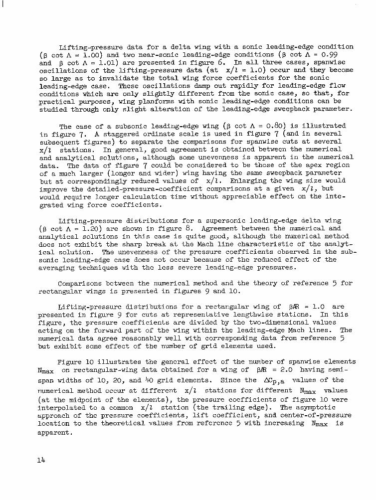
Comparisons between the numerical method and t h e theory of reference 5 f o r rectangular wings i s presented i n f igures 9 and 10.
Lifting-pressure d is t r ibu t ions f o r a rectangular wing of p R = 1.0 a r e presented i n f igure 9 f o r cuts a t representat ive lengthwise s ta t ions . f igure, t he pressure coef f ic ien ts a r e divided by t h e two-dimensional values act ing on the forward p a r t of the wing within the leading-edge Mach l ines . The numerical data agree reasonably w e l l with corresponding data from reference 5 but exhibi t some e f f e c t of t he number of g r i d elements used.
I n t h i s
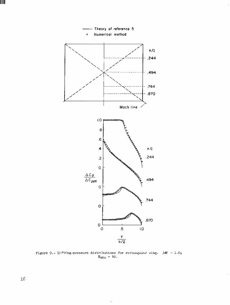
Figure 10 i l lustrates the general e f f ec t of t he number of spanwise elements "ax on rectangular-wing data obtained fo r a wing of pR = 2.0 having s e m i - span widths of 10, 20, and 40 g r id elements. Since t h e N p , a values of t h e numerical method occur a t d i f f e ren t x/2 s t a t ions f o r d i f fe ren t Nmx values (a t the midpoint of the elements), t he pressure coef f ic ien ts of f igure 10 w e r e in terpolated t o a common x/2 s t a t ion ( the t r a i l i n g edge). The asymptotic approach of the pressure coeff ic ients , l i f t coef f ic ien t , and center-of-pressure locat ion t o the theo re t i ca l values from reference 5 with increasing "ax i s apparent.
14

Theory of reference 4 o Numericol method
B cot A=0.80
,
x 11
.20, .40 70 1.00
. I 0
B ACp a
0
0
0- 0 .5 1.0
Y b/2 -
Figure 7.- Lifting-pressure distri- butions fo r subsonic leading-edge de l ta wing. N- = 50.
- Theory of reference 4 0 Numerical method
B cot A 1.20
\Mach line
PAC, 1.00 Q
Y b/2
Figure 8. - Lifting-pressure dis t r ibut ions f o r supersonic leading-edge de l ta wing. N- = 50.
I
Theory of reference 5 0 Numerical method
.494
,744
.870
Moch l i n e J I
.494
.744
,870
0 .5 1.0
Y b /2 -
Figure 9.- Lifting-pressure distributions for rectangular wing. P A 3 = 1.0; N" = 40.
16
I
M = 1.414
CL
CL,m
xcp 1
M = 1.667
Theory of reference 5 o Numerical method
0.0307 [ 0.687 I 0.0449 . . ~
’“A.
0.686
X T 1.0
.8
.9 I
.6 .7 t
.5 i
.4 L I
0
O O 0
20 40
“ax
Nmax
IO
20
40
Y b / 2 __
Figure 10.- Effect of Nmax on characteristics of rectangular wing. PAR = 2.0.
Lifting-pressure distributions for a more complex planform geometry, the double-delta type, are shown in figure 11 where the numerical-method data are compared with the theoretical data obtained from the superposition solution of reference 6. numerical method exhibit approximately the same areas under the lifting-pressure curves as the superposition solution, although no sharp peaks occur in the numerical method. two solutions likewise shows reasonable agreement:
For both Mach numbers (M = 1.414 and 1.667), the data from the
A comparison of the wing force coefficients obtained by the
..
-
Superposition analysis . . . . . - -
Numerical method . . . . . . . . given
I

Theory of Numerical
----.go
aCp a
M = 1.414
x 11 .I 6
.I 2
.08
.04
0
I . OO .5 .O
M = 1.667
x 11
.50
OO m .5 1.0
Figure 11.- Lifting-pressure distributions for double-delta wing. Nmax = 50.
A f i n a l comparison i l l u s t r a t i n g the use of t h e numerical method t o estimate t h e l inear-theory charac te r i s t ics of a wing family i s presented i n f igure 12, where the l i f t -curve slope of a wing series having an unswept midchord and a constant taper r a t i o of 0.5 i s shown f o r a Mach number of 1-33. Reasonable agreement between the numerical method and the theory of reference 7 w a s obtained. ( I n order t o l i m i t ca lculat ion t i m e , a value of N m a of 25 w a s used for t he wing with an aspect r a t i o of 1.)
18

- Theory of reference 7 o Numerical method
1
I 2 3 4 5 6
A3
Figure 12.- Lift-curve slope of wing series having unswept midchord. A = 0.5; M = 1.53
Application of Numerical Method t o Wings of Arbitrary Planform
Several examples of t he use of t he numerical method t o estimate the aero- dynamic charac te r i s t ics of wings having cranked or curved leading edges a re presented i n f igures 13 t o 17.
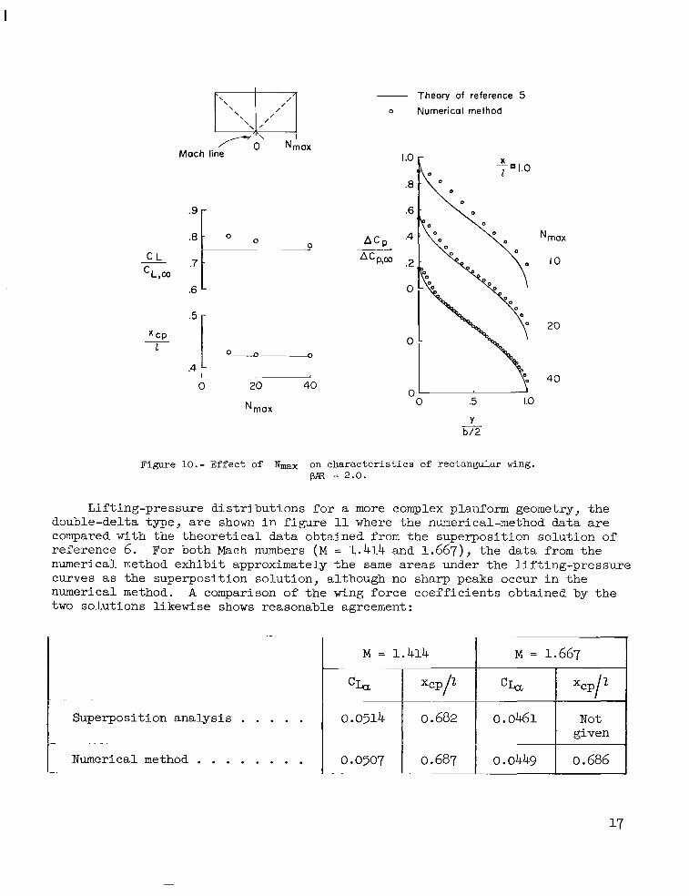
The charac te r i s t ics of an M-wing planform having symmetric apexes a t 0.30 semispan are i l l u s t r a t e d i n figure 13. equally on e i t h e r s ide of t he apexes, and the t r a i l i n g edge i s notched varying amounts. ( f i g . 4), t he M wing has a generally higher l i f t -curve slope f o r has the same l i f t -curve slope f o r p cot A > 1.0 of t he inf in i te -aspec t - ra t io wing), and has a center-of-pressure locat ion fo r - ward of t h a t of the de l t a wing by approximately 2 percent of t he wing length. The e f f ec t of t he trail ing-edge notch on t h e M wing i s t o carve out a r e l a t ive ly low l i f t area, increasing the l i f t -curve slope of t he remaining wing.
The wing leading edge i s sweptback
Compared with a de l t a wing having the same sweepback parameter p cot A < 1.0,
(equal t o t h e l i f t -curve slope
The e f f ec t of apex posi t ion on the aerodynamic charac te r i s t ics of an M-wing family i s shown i n f igure 14 f o r
e i t h e r s ide of the apexes as before. Apex posi t ions - of 0 and 0.53 (or
greater) correspond t o a s ingle and an i so l a t ed p a i r of arrow wings, respec- t i ve ly . not la rge (approximately 5 percent f o r the unnotched planforms) and va r i e s only s l i g h t l y over a range of apex posi t ions from 0.20 t o 0.40 semispan. The corre- sponding s h i f t i n center of pressure i s a l s o ra ther s m a l l . e s t i ng e f f e c t of notching t h e M-wing planforms may be observed from the data of
p c o t A = 0.80, with symmetric sweepback on
b/2
The e f f e c t of apex posi t ion on the l i f t - c w e slope of t he family i s
However, an i n t e r -
.30 b/2
I
.6
5 - xcp
.7 r - 0
.2 - .4
_- -- . - .- -- -- - 7---- Sonic
trailing edge
e N
Figure 13.- Characteristics of M-wing family with apex at 0.30 semispan.
_- _ _ _ __---- - .2 .06 0
Sonic trailing edge
0 . I .2 .3 A .5 .6
L b / 2
Figure 14.- Effect of apex position on characteristics of M-wing family. p cot A = 0.80.
f igures 14 and 13. The notch-ratio data were obtained by removing sections of t he de l t a type of t r a i l i n g edge, a process which i s p a r t i a l l y inva l id because of the assumption of a supersonic t r a i l i n g edge. The wing area having inva l id
pressure dis t r ibut ions i s t h a t shown cross-hatched i n the sketch; t he corresponding aerodynamic charac te r i s t ics are indicated by dashed l i n e s i n f igure 14. These data a r e included because of t he ins ight offered i n t o the pressure distribut. ions on the
Mach l i n e
Sonic t r a i l i n g edge M-wing planform.
The M wing with varying apex posit ion may be a l te rna t ive ly regarded as a The cuts across the wing of w i n s of f ixed zpex posi t ion of varying length.
f igure 15 correspond t o wings having apex posit ions of 0.53, 0.40, 0.30, 0.25, and 0.21 semispan (x/2 = 0.22, 0.38, 0.58, 0.75, and 0.96, respectively).
20
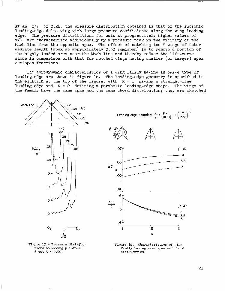
A t an x/Z of 0.22, the pressure dis t r ibut ion obtained i s tha t of the subsonic leading-edge del ta wing with large pressure coeff ic ients along the wing leading edge. The pressure d is t r ibu t ions f o r cuts a t progressively higher values of x/Z Mach l i n e from the opposite apex. The e f fec t of notching the M wings of i n t e r - mediate length (apex a t approximately 0.30 semispan) i s t o remove a portion of the highly loaded area near the Mach l i n e and thereby reduce the l i f t -curve slope i n comparison with t h a t fo r notched wings having smaller (or l a rger ) apex semispan fract ions.
a re characterized addi t ional ly by a pressure peak i n the v i c in i ty of the
The aerodynamic charac te r i s t ics of a wing family having an ogive type of leading edge a re shown i n f igure 16. The leading-edge geometry i s specified i n the equation a t the top of the figure, with K = 1 giving a s t ra ight - l ine leading edge and K = 2 defining a parabolic leading-edge shape. The wings of the family have the same span and the same chord dis t r ibut ion; they a re sketched
.E
.a P ACp __ a
.01
0
0
0
0
0
x / 2
2 I I
.6 r
I I
.5 1.0 I 1.5 2 y b/2
Figure 15.- Pressure dis t r ibu- t ions on M-wing planform. B cot A = 0.80.
K
Figure 16.- Characterist ics of wing family having same span and chord dis t r ibut ion.
21
f o r representative members having aspect r a t i o s of 2.24. eters are presented, a l l corresponding t o a subsonic leading-edge condition f o r
t h e arrow wing, a s shown. The l i f t - curve slope of the parabolic leading- edge wing i s approximately 8 percent higher than t h a t f o r the arrow wing, with an accompanying la rge forward s h i f t i n t h e streamwise center of
Three sweepback param-
I
Leading-edge equation: p =.6 + .4 - (b$ (L2Y
A A A a pressure.
.04 1 .8 r n
.5 I I
0 2 4 6 8 10
K
Figure 17.- Characteristics of ogee fam- - - i l y having same span and length.
( p cot = 0.80.
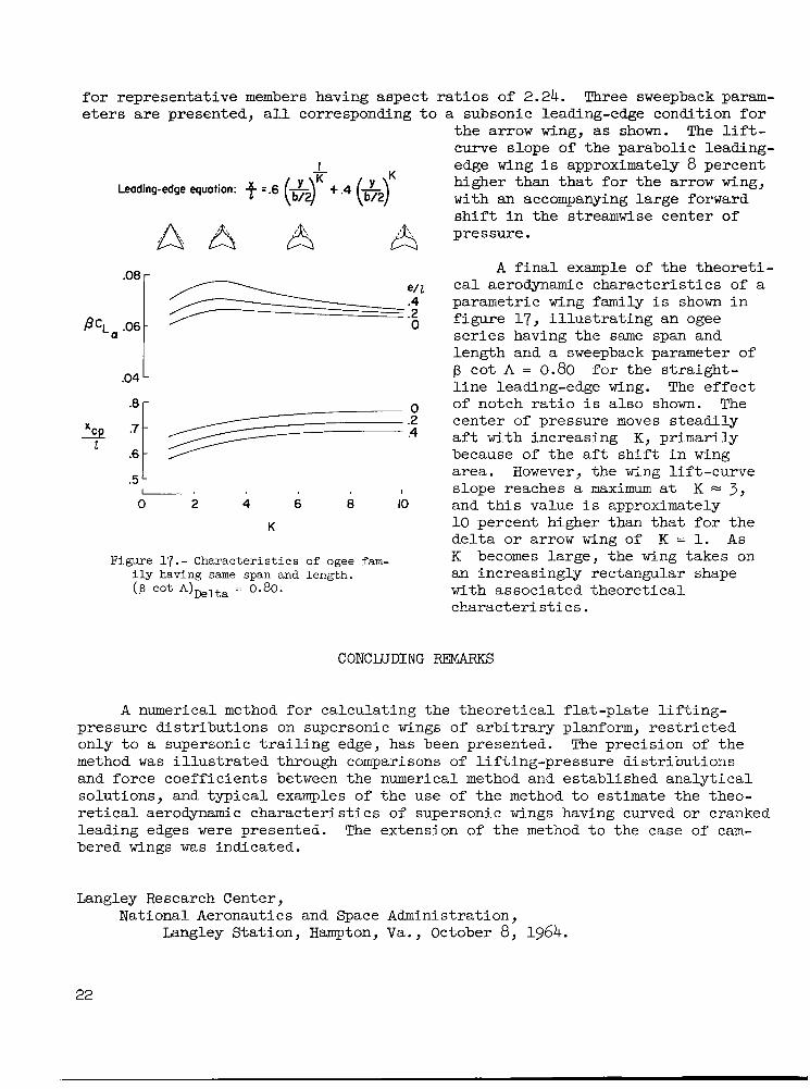
A f i n a l example of t h e theore t i - c a l aerodynamic charac te r i s t ics of a parametric wing family i s shown i n figure 17, i l l u s t r a t i n g an ogee series having the same span and length and a sweepback parameter of p cot A = 0.80 l i n e leading-edge wing. The e f f ec t of notch r a t i o i s a l so shown. The center of pressure moves s t ead i ly a f t with increasing K, primarily because of t he a f t s h i f t i n wing area. However, the wing l i f t -curve slope reaches a maximum a t K = 3 , and t h i s value i s approximately 10 percent higher than t h a t f o r t h e de l t a o r arrow wing of K = 1. A s K becomes large, the wing takes on an increasingly rectangular shape with associated theore t ica l charac te r i s t ics .
f o r the s t r a igh t -
CONCLUDING REMARKS
A numerical method f o r calculat ing the theo re t i ca l f l a t -p l a t e l i f t i n g - pressure d is t r ibu t ions on supersonic wings of a r b i t r a r y planform, r e s t r i c t e d only t o a supersonic t r a i l i n g edge, has been presented. method was i l l u s t r a t e d through comparisons of l i f t ing-pressure d is t r ibu t ions and force coeff ic ients between the numerical method and established ana ly t ica l solutions, and typ ica l examples of t he use of t h e method t o estimate the theo- r e t i c a l aerodynamic charac te r i s t ics of supersonic wings having curved o r cranked leading edges were presented. The extension of t he method t o the case of cam- bered wings was indicated.
The precision of t he
Langley Research Center, National Aeronautics and Space Administration,
Langley Stat ion, Hampton, Va., October 8, 1964.
22

1. Carlson, Harry W.; and Middleton, Wilbur D.: A Numerical Method for t he Design of Camber Surfaces of Supersonic Wings With Arbitrary Planforms. NASA TN D-2341, 1964.
2. Lomax, Harvard; Heaslet, Max. A.; and Fuller, Franklyn B.: Integrals and Integral Equations i n Linearized Wing Theory. NACA Rep. 1034, 1951. (Supersedes NACA TN 2252. )
3. Mangler, K. W.: Improper Integrals i n Theoretical Aerodynamics. Rep. No. Aero. 2424, Bri t i sh R.A.E., June 1951.
4. Puckett, A. E. ; and Stewart, H. J.: Aerodynamic Performance of Delta Wings a t Supersonic Speeds. J. Aeron. Sc i . , vol. 14, no. 10, Oct. 1947, PP. 567-578.
5. Bonney, E. Arthur: Aerodynamic Characterist ics of Rectangular Wings a t Supersonic Speeds. J. Aeron. Sc i . , vol . 14, no. 2, Feb. 1947, pp. 110-116.
6. Cohen, Doris; and Friedman, Morris D.: Theoretical Investigation of t he Supersonic L i f t and Drag of Thin, Sweptback Wings With Increased Sweep Near the Root. NACA TN 2959, 1953.
7. Nielsen, Jack N. ; Matteson, Frederick H.; and Vincenti, Walter G. : Invest i - gation of Wing Character is t ics a t a Mach Number of 1.53. 111 - Unswept Wings of Differing Aspect Ratio and Taper Ratio. NACA RM ~ 8 ~ 0 6 , 1948.
NASA-Langley, 1965 L-4071
111111 I111
“The aeronautical and space activities of the United States shall be conducted so as to contribufe . . . to the expansion of human knowt- edge of phenomena in the atmoJphere and space. The Administration shall provide for the widest practicable and appropriate dissemination of information concerning its activities and the results thereof .’’
-NATIONAL AERONAUTICS AND SPACE ACT OF 1958
NASA SCIENTIFIC AND TECHNICAL PUBLICATIONS
TECHNICAL REPORTS: important, complete, and a lasting contribution to existing knowledge.
TECHNICAL NOTES: of importance as a contribution to existing knowledge.
TECHNICAL MEMORANDUMS: Information receiving limited distri- bution because of preliminary data, security classification, or other reasons.
CONTRACTOR REPORTS: Technical information generated in con- nection with a NASA contract or grant and released under NASA auspices.
TECHNICAL TRANSLATIONS: Information published in a foreign language considered to merit NASA distribution in English.
TECHNICAL REPRINTS: Information derived from NASA activities and initially published in the form of journal articles.
SPECIAL PUBLICATIONS: Information derived from or of value to NASA activities but not necessarily reporting the results .of individual NASA-programmed scientific efforts. Publications include conference proceedings, monographs, data compilations, handbooks, sourcebooks, and special bibliographies.
Scientific and technical information considered
Information less broad in scope but nevertheless
Details on the availability o f these publications may be obtained from:
SCIENTIFIC AND TECHNICAL INFORMATION DIVISION
N AT1 0 N A L A E R 0 N AUT1 CS AN D SPACE A D M I N I ST RAT1 0 N
Washington, D.C. PO546