nasa technical memorandum effects of · pdf filethe results presented in reference 2 are for...
TRANSCRIPT

NASA TECHNICAL MEMORANDUM 100558
EFFECTS OF MOISTURE, ELEVATED TEMPERATURE, AND
FATIGUE LOADING ON THE BEHAVIOR OF GRAPHITEIEPOXY
BUFFER STRIP PANELS WITH CENTER CRACKS
C. A. BIGELOW
(HA SA-TB-1OO5 5 8 ) EPPECTS OF HO XSTUR g m a - 19590 ELEVATED TPBPEBATURE, AND PATXGUE L O A D I Y G OBI THE B E H A V I O R OF GRAPBITE/EPOXY BUFFER S T R I P P1LNELS YXTH CENTER CRACKS { N I S A ) 27 p Dnclas
CSCL 11D 63/24 0128901
FEBRUARY 1988
National Aeronautics and Space Administration
Langley Research Center Hampton, Virginia 23665
https://ntrs.nasa.gov/search.jsp?R=19880010206 2018-05-25T04:57:34+00:00Z

SUMMARY
The effects of fatigue loading combined with moisture and heat
on the behavior of graphite/epoxy panels with either Kevlar-49 or S-glass
buffer strips were studied. Buffer strip panels, that had a slit in the
center to represent damage, were moisture conditioned or heated, fatigue
loaded, and then tested in tension to measure their residual strength. Panels
were made with a [45/O/-45/90]2s layup with either Kevlar-49 or S-glass buffer
strip material.
were made by replacing narrow strips of the 0-degree graphite plies with
Kevlar-49/epoxy or S-glass/epoxy on a one-for-one basis.
subjected to a fatigue loading spectrum with two levels of maximum strain and
five different durations of the fatigue spectrum.
preconditioned by soaking in 60° C water to produce a 1% weight gain then
tested at room temperature.
loading.
Also, panels from each group were tested to determine their residual strengths
without fatigue loading.
The buffer strips were parallel to the loading direction and
The panels were
One group of panels was
One group was heated to 82O C during the fatigue
Another group was moisture conditioned and then tested at 82O C.
As expected, for the panels without fatigue loading, the buffer strips
arrested the crack growth and increased the residual strengths significantly
over those of laminates without buffer strips under all conditions.
for the S-glass buffer strip panels with moisture conditioning, the increase
in the residual strength was less than for the other conditions.
However,
For the panels subjected to fatigue loading, the residual strengths were
not significantly affected by the fatigue loading, the number of repetitions
of the loading spectrum, or the maximum strain level. The moisture
conditioning reduced the residual strengths of the S-glass buffer strip

panels by 10 to 15% below the ambient results.
not have a significant effect on the Kevlar-49 panels.
affect the panel strengths of the buffer strip panels for either buffer
material.
the fatigue loading, the moisture, the elevated temperature, or the
combination of moisture and elevated temperature.
did not produce any damage growth at the crack tips.
The moisture conditioning did
The heating did not
The stiffnesses of the panels were not significantly affected by
The fatigue cycling also
These results show that the improved fracture strength produced by the
buffer strip configuration is not significantly degraded by fatigue loading,
by elevated temperature, or by moisture conditioning, except for the moisture-
conditioned S-glass buffer material.
INTRODUCTION
The high strength-to-weight and stiffness-to-weight ratios of advanced
fiber-reinforced composites, such as graphite/epoxy, make them one of the
outstanding primary structural materials in the aeronautical industry.
Despite many efforts in the past to understand their mechanical performance,
there still remain important technical questions to be answered before
extensive use of composite materials will occur.
the long-term mechanical performance under conditions of moisture and elevated
temperatures. When subjected to fatigue loading, composites can exhibit
several modes of damage including delamination, fiber failure and matrix
cracking.
development and propagation.
One such question concerns
Moisture and elevated temperature can also effect damage
In static tests, the buffer strip configuration has been shown to greatly
improve the damage tolerance of graphite/epoxy panels subjected to tension
2

. loads (ref. 1). The buffer strips act to contain the damage and result in
much higher residual strengths for cracked or damaged panels. In ref. 1, the
fractures in the buffer strip panels were shown to initiate at approximately
the failing strain of a plain panel (i.e., a panel without buffer strips), run
into the buffer strips, and stop. The load was increased and the panels
eventually failed at strains higher than those at which the fractures
initiated and at which the plain panel would have failed.
In earlier work (ref. 2), the effects of fatigue loading on the behavior
of graphite/epoxy panels with either Kevlar-49 or S-glass buffer strips were
studied. The results presented in reference 2 are for unconditioned buffer
strip panels tested at room temperature. Herein, the results presented in
reference 2 will be referred to as the ambient results. At ambient
conditions, the residual strengths of the panels were not affected by the
fatigue loading.
changed by the fatigue loading. In all cases, the buffer strips arrested the
cracks and increased the residual strengths significantly over those of
laminates without buffer strips.
Also, the stiffnesses of the panels were not significantly
The purpose of the present investigation was to study the effects of
fatigue loading, elevated temperature, and moisture on the behavior of
graphite/epoxy buffer strip panels. Accordingly, graphite/epoxy buffer strip
panels were subjected to a fatigue loading spectrum and then statically tested
in tension to determine their residual strengths. One layup was used,
[45/0/-45/90]2s, with two different buffer strip materials:
glass.
reached; some were heated in an oven during the fatigue and static loading
portions of the tests; others were soaked in water and heated during loading.
Each panel was cut in the center to represent damage.
Kevlar-49 or S -
Some panels were soaked in water until a weight gain of 1% was
Panel strains and
3

crack-opening-displacements were measured to indicate panel stiffness and the
extent of damage at the crack tips.
‘The r e s i d u a l st.rc?ng:tl.c; of t he fatigued panels arc: compared to the
residual strength of a buffer strip panel without spectrum loading and to the
residual strength of a graphite/epoxy panel without buffer strips.
Comparisons were made for both buffer materials for moisture conditioning,
heat and the combination of moisture and heat.
cycling, moisture, and heat on the panel stiffness and the crack-tip damage
state were periodically measured during the fatigue cycling.
The effects of fatigue
EXPERIMENTAL PROCEDURES
Materials and Specimens
The panels were made with T300/5208 graphite/epoxy in a 16-ply quasi-
isotropic layup, [45/0/-45/90]2s. Each panel had four evenly spaced buffer
strips parallel to the load direction. The panel configuration is shown in
Figure 1. The buffer strips were made from two different materials: Kevlar-
49/5208 or S-glass/5208 tape. All the panels were 102 mm wide constructed
with 5-mm-wide buffer strips spaced 20 mm apart, with slits 10 mm long and
0.020 (k0.002) mm wide cut in the center of the panel to represent damage (see
Fig. 1).
degree graphite plies with strips of either 0-degree Kevlar-49 or S-glass on a
one-for-one basis.
same batch of material and in the same configuration as those used in ref. 2 .
The buffer strips were made by replacing narrow strips of the 0-
The panels used in the present study were made from the
Moisture and Heat Conditioning
One group of panels was soaked in water before testing. To accelerate
the absorption rate, the water was held at a temperature of 60° C.
remained in the heated water until a weight gain of 1% was measured. At that
The panels
4

time, the panels were removed from the water, weighed, and stored in water-
tight containers until testing. As the test time was relatively short, no
attempt was made to maintain the moisture level during testing.
were mounted on these panels with a coating to prevent debonding of the strain
gages during soaking. However, the coating was not very effective; some of
the strain gages did debond during the moisture conditioning.
Strain gages
For the elevated temperature tests, an oven was mounted on the test stand
and closed around the test section of the panel.
panel length was enclosed in the oven.
least an hour before testing to insure thermal equilibrium during each test.
The temperature was held constant for the duration of the test.
Approximately 178 mm of the
The panels were heated to 82O C for at
Test Procedures and Equipment
The panels were tested under a fatigue spectrum loading. MINITWIST (ref.
3 ) , a shortened version of a standardized load program for the wing lower
surface of a transport aircraft, was chosen to provide a realistic load
history for the panels.
with each flight consisting of about 15 load cycles on average.
load in the MINITWIST spectrum occurs only once. The tests were run at
approximately 5 Hz. One repetition of the MINITWIST spectrum took
approximately 4 hours.
The complete MINITWIST spectrum contains 4000 flights
The maximum
Tables 1 and 2 show the test matrices that were used for the panels
containing the Kevlar-49 and S-glass buffer strips, respectively. Each group
of panels made with the Kevlar-49 or the S-glass buffer strip material was
divided into three sets: (1) panels that were conditioned by soaking in
heated (60° C) water; (2) panels that were heated to 82O C in an oven before
and during the spectrum loading; and ( 3 ) panels that were conditioned by
5

soaking in heated water and heated in the oven before and during the spectrum
loading. Within each set, several different continuous repetitions (as shown
in Tables 1 and 2) of the MINITWIST spectrum were used. Additionally, two
values of the maximum strain level in the spectrum were used. An average
strain of 0.005 is often used as the ultimate design strain in wing panels
(ref. 4 ) ; thus, the values of 0.005 and 0.006 were chosen as two realistic
values of ultimate design strain for an actual structure.
values of maximum strain used in the MINITWIST spectrum were 0.0035 and
0.0042.
prevent compression buckling during the air-ground-air cycle of the MINITWIST
spectrum. After the fatigue loading, all panels were statically loaded in
tension to failure to determine their residual strengths.
The corresponding
Guide plates were mounted on the panels during the fatigue loading to
Periodically during the fatigue cycling in all tests, the spectrum
loading was stopped and the panel was statically loaded in tension to the
prescribed maximum strain. During these static load segments, load versus
remote strain, load versus strain in the buffer strip next to the crack tip
and load versus crack-opening-displacement (COD) were recorded. Strain gages
were located on the panels as indicated in Figure 1. The COD was measured
using a ring gage. These data was used to determine if the fatigue loading
had produced any change in the panel stiffness or resulted damage growth at
the crack tip as measured by the slope of the load-strain curves or the load-
COD curves.
A number of plain graphite/epoxy tensile coupons and center-cracked
fracture specimens were made at the same time and from the same batch of
material as the buffer strip panels. Some of these specimens were moisture
conditioned or heated the same as the buffer strip panels and then tested
statically in tension to determine what effects, if any, the moisture or heat . 6

.
had on the laminate. Tensile coupons 25.4-mm wide were tested to determine
the longitudinal modulus. Fracture specimens 102-mm wide with a center crack
equal in length to the buffer strip spacing were tested to determine the
residual strength of the plain graphite/epoxy panels.
RESULTS AND DISCUSSION
Plain Panels
As previously mentioned, a number of plain graphite/epoxy tensile coupons
and center-cracked fracture specimens were made and tested statically under
the same conditions as the buffer strip panels. Table 3 shows results from
these tests. For comparison, Table 3 also shows the modulus and residual
strength for the room temperature tests reported in ref. 2. The results in
Table 3 show that neither the moisture nor the heat had an effect on the
longitudinal modulus of the material.
effect on the residual strength of the plain panel; the moisture conditioning,
however, increased the residual strength of the plain panel slightly (less
than 5%) over the room temperature value.
The heat did not have a significant
Residual Strengths
Kevlar-49 Buffer Strip Material. Figure 2 shows the residual strengths
for the Kevlar-49 buffer strip panels, with and without fatigue loading.
results plotted are the averages for each test condition of the test data
shown in Table 1.
graphite/epoxy panels without fatigue loading.
The
Also shown are the residual strengths of the plain
For the panels without fatigue loading, Figure 2 shows that, as expected,
the residual strengths of the buffer strip panels were significantly higher
(35%) than the residual strengths of the plain panels. The residual strengths
7

of the moisture-conditioned buffer strip panels were slightly below the
residual strengths of the heat-conditioned buffer strip panels.
For the buffer strip panels with fatigue loading, Figure 2 compares the
residual strengths for various numbers of repetitions of the MINITWIST
spectrum as well as for the two maximum strain levels used. The figure shows
that neither the level of the maximum strain nor the number of repetitions of
the MINITWIST spectrum had a significant effect on the residual strengths of
the buffer strip panels.
of the fatigued panels were only slightly below the residual strengths of the
Kevlar-49 buffer strip panels without fatigue loading.
Figure 2 also shows that moisture conditioning, heat, or the combination
In the majority of the cases, the residual strengths
of both had virtually the same effect on the residual strengths of the panels.
On average, the residual strengths shown in Figure 2 are slightly higher than
the results for ambient conditions (ref. 1). For all conditions, the failing
strengths were higher than for similar graphite/epoxy panels without buffer
strips; thus, the fractures were arrested by the buffer strips under all
conditions.
Table 1 also lists the residual strengths and failure strains of the
Kevlar-49 buffer strip panels for each test condition. The residual strengths
of Kevlar-49 buffer strip panels with moisture or heat, but without fatigue
loading, are also given in Table 1. Such strengths were not measured for
panels with combined moisture and heat.
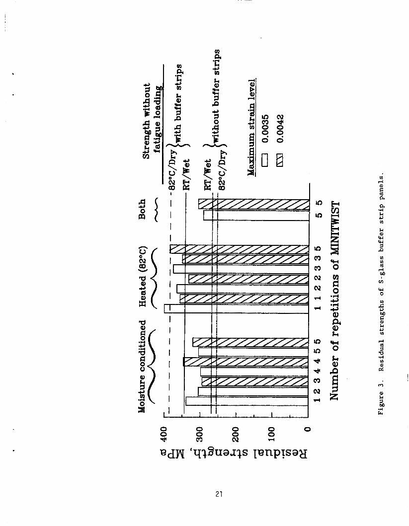
S-Glass Buffer Strip Material. Figure 3 shows the residual strengths for
A l s o shown the S-glass buffer strip panels, with and without fatigue loading.
in the figure are the residual strengths of the plain graphite/epoxy panels
without fatigue loading. . 8

For the panels without fatigue loading, Figure 3 shows that, as expected,
the residual s t r e n g t h s of t h c buffer strip panels were significantly higher
I t i ; l r i t r i r . r c a * ; j d l i ; l l ! , I r c ~ r i ~ ; t l ~ ~ ~ of I t i c - p l a i n panc*ls . For t h e S-glass buffer strip
material, the residual strengths of the moisture-conditioned buffer strip
panels were well below (by 11%) the residual strengths of the heated buffer
strip panels.
panel tested under ambient conditions is approximately equal to the heated
results.) Thus, although the fractures were arrested by the buffer strip, for
the moisture conditioned panels, the effectiveness of the buffer strip
configuration was reduced compared to the heated or ambient results.
(Although not shown in the figure, the residual strength of a
For the panels with fatigue loading, Figure 3 compares the residual
strengths for various numbers of repetitions of the MINITWIST spectrum as well
as for the two maximum strain levels used.
test condition neither the level of the maximum strain nor the number of
repetitions of the MINITWIST spectrum had a significant effect on the residual
strengths of the buffer strip panels.
strengths of the fatigued panels did not differ significantly from the
strength of the panels without fatigue loading.
moisture-conditioned panels were lower (by up to 14%) than the residual
strength of the moisture conditioned S-glass buffer strip panel without
fatigue loading.
The figure shows that within each
For the heated panels, the residual
The residual strengths of the
Figure 3 shows that the moisture conditioning had a marked effect on the
residual strengths of the S-glass buffer strip panels.
results shown for the moisture-conditioned S-glass panels are approximately
15% below the results for the heated S-glass panels and 10% below results for
ambient conditions (ref. 2 ) . A similar reduction is seen for the panels that
were moisture conditioned and heated.
On average, the
The reduction for the S-glass buffer
9

strip panels, with and without fatigue, is not entirely unexpected, since as
demonstrated in reference 5, the ultimate tensile strength of a E-glass/1009
resin system decreased continuously with increasing amounts of water
absorption.
approximately equal to the ambient results (ref. 2). As before, the failing
strengths of the S-glass buffer strip panels were higher than for similar
graphite/epoxy panels without buffer strips; thus, the fractures were arrested
by the buffer strips under all conditions.
strip material, the moisture conditioning significantly reduced the
effectiveness of the buffer strip.
For the heated panels, the results shown in Figure 3 are
Although for the S-glass buffer
Table 2 lists the residual strengths and the failure strains of the S-
glass buffer strip panels for each test condition. The residual strengths of
the S-glass buffer strip panels with moisture or heat, but without fatigue
loading, are also given in Table 2.
S tiff nes s
During the fatigue cycling, load versus strain plots were made
periodically to monitor the panel stiffness. Figures 4 and 5 show two sets of
typical plots that were made for panels that were moisture conditioned.
Figure 4 shows a series of strain versus load plots for a Kevlar-49 buffer
strip panel with a maximum strain level of 0.0035 and Figure 5 shows a series
of strain versus load plots for a S-glass buffer strip panel with a maximum
strain level of 0 .0042 . Five repetitions of the MINITWIST spectrum were
applied to each panel. (Notice that an offset of 10 kN is used for each
subsequent plot in Figures 4 and 5.) These plots are typical of all the test
results.
10

As mentioned earlier, one repetition of the MINITWIST spectrum simulates
l+OOO flights for a transport: w ng structure and during the normal MINITWIST
cycle, the maximum load is app ied only once. As shown in the figure, data
was plotted before the spectrum loading began ( 0 flights) then the fatigue
cycling was stopped and data was plotted after 1 repetition (4000 flights),
after 2 repetitions (8000 flights), after 3 repetitions (12000 flights), after
4 repetitions (16000 flights), and after 5 repetitions (20000 flights) of the
spectrum. In this test program, each buffer strip panel was loaded to the
maximum load level during each periodic plot such as those shown in Figures 4
and 4 . This means that the maximum load level was applied several more times
than called for in the MINITWIST spectrum itself. For the results shown in
Figures 4 and 5 , the maximum load was applied six times beyond what was
applied in the repetitions of MINITWIST. The number of extra maximum loads
applied depended upon the number of times the fatigue cycling was interrupted
to statically load the panel to the prescribed maximum strain level and ranged
from two to six.
severe test of the panel than the spectrum loading alone would have.
These extra applications of maximum load produced a more
The moisture conditioning, the heat, or the combination of moisture and
heat did not affect the load-strain behavior of the buffer strip panels.
periodic load versus strain plots were nearly identical for all conditions,
and were very similar to the ambient results given in ref. 2 . Thus, there was
no change in the overall panel stiffness due to any of the test conditions.
Although the water absorption caused a significant change in the residual
strengths of the S-glass buffer strip panels, no change was seen in the
stiffness of these panels. Reference 5 also observed no significant change in
the modulus of the glass/epoxy due to water absorption.
The
11

Crack Opening Displacements
During the fatigue cycles, crack-opening-displacement (COD) versus load
plots were made periodically to monitor the damage state at the crack tip.
Figures 6 and 7 show two sets of typical COD versus load plots for panels that
were moisture conditioned. The plots in Figures 6 and 7 are for the same
panels used in Figures 4 and 5.
the results for all the buffer strip panels. For the panel with the maximum
strain level of 0.0035 (Figure 6 ) , there was no indication of any damage
growth; the slope of the COD-load plots remained constant. For the panel with
the maximum strain level of 0.0042 (Figure 7), there was some damage growth at
the crack tips, as indicated by the sharp jump in the COD versus load plot for
the initial load segment (0 repetitions). However, there was no significant
change in the slope of the subsequent plots nor in the slopes of the load
versus strain plots shown in Figure 7.
damage state at the crack tip.
the panels loaded to the maximum strain value of 0.0042 and only in the
initial loading segment. There was no damage growth due to the fatigue
loading. There was no indication of any initial damage growth for the panels
The data shown in these plots are typical of
Thus, there was no change in the
The jumps on the COD plots were seen only for
with the maximum strain level of 0.0035.
Strains
The failing strains of the buffer str-2 panels are listed in Tables 1 and
2 . The data given in these tables show that the majority of the actual
failing strains of the panels were much higher than the assumed ultimate
design strain levels of 0.005 and 0.006.
to 1.5 times the design ultimate. The exceptions here were the S-glass buffer
strip panels that had been moisture conditioned.
The failing strains ranged from 1.1
The actual failing strains
1 2

.
of those panels (see Table 2) were close to the assumed ultimate design strain
of 0.006. ‘Thus, except f o r the inoisture-conditioned S-glass panels, the
spectrum loading did not test the buffer strip panels as severely as it might
have. The failing strains of the S-glass buffer strip panels subjected to
moisture conditioning were also significantly lower than the ambient results
(ref. 2 ) . However, the failing strains of the rest of the panels were
approximately equal to the ambient results reported in ref. 2.
CONCLUDING REMARKS
Graphite/epoxy buffer strip panels were tested to measure their residual
tension strength after fatigue spectrum loading combined with moisture and
heat. Panels were made with a [45/0/-45/90],s layup. The buffer strips were
made by replacing narrow strips of the O-degree graphite plies with strips of
either O-degree Kevlar-49 or S-glass on a one-for-one basis.
slit in the center between buffer strips to represent damage.
The panels were subjected to a fatigue loading spectrum, MINITWIST, a
The panels had a
shortened version of a standardized load program for the wing lower surface of
a transport aircraft.
with five different durations of the fatigue spectrum.
was preconditioned by soaking in heated water until a 1% weight gain was
measured. One group was heated in an oven before and during the fatigue
loading. Another group was moisture conditioned and heated. Buffer strip
panels from each group were statically loaded in tension to failure to
determine their residual strengths without fatigue loading. During fatigue
loading, periodic plots of load versus strain and load versus crack-opening-
displacements were made to monitor the panel stiffness and the damage state at
Two levels of maximum strain were used in the spectrum
One group of panels
13

the crack tip. After fatigue loading, all panels were statically loaded in
tension to failure to determine their residual strengths.
As expected, for the panels without fatigue loading, the buffer strips
arrested the crack growth and increased the residual strengths significantly
over those of plain panels under all conditions.
buffer strip panels with moisture conditioning, the increase in the residual
strength was less than for the other conditions.
However, for the S-glass
For the panels subjected to fatigue loading, the residual strengths were
not significantly affected by the fatigue loading, the number of repetitions
of the loading spectrum, or the maximum strain level.
conditioning had a significant effect on the residual strengths of the S-glass
buffer strip panels, reducing the residual strengths by 10 to 15% below the
ambient results.
of the Kevlar-49 buffer strip panels slightly over the ambient results.
heat increased the residual strengths of the buffer strip panels slightly over
the ambient results for both buffer strip materials. The stiffnesses of the
panels were not significantly affected by the fatigue loading, the moisture,
the elevated temperature, or the combination of moisture and elevated
temperature.
the crack tips.
The moisture
The moisture conditioning increased the residual strengths
The
The fatigue cycling also did not produce any damage growth at
These results show that the improved fracture strength produced by the
buffer strip configuration is not significantly degraded by fatigue loading,
by elevated temperature conditions, or by moisture conditions, except for the
moisture-conditioned S-glass buffer material.
14

REFERENCES
1. Poe, C. C., Jr.; and Kennedy, J. M.: An Assessment of Buffer Strips for Improving Damage Tolerance of Composite Laminates. Journal of Composite Materials Supplement, vol. 14, 1980, pp. 57-70.
2 . Bigelow, C. A.: Fatigue of Graphite/Epoxy Buffer Strip Panels with Center Cracks. NASA TM-87595, August 1985.
3. Lowak, H.; de Jonge, J. B.; Franz, J.; and Schutz, D.: MINITWIST A Shortened Version of TWIST. Nationaal Lucht - En Ruimtevaartlaboratorium, NRL MP 79018 U, ICAF Document 1147, Jan. 1979.
4. Williams, J. G.; Anderson, M. S.; Rhodes, M. D.; Starnes, J. H., Jr.; and Stroud, W. J.: Recent Developments in the Design, Testing and Impact-Damage Tolerance of Stiffened Composite Panels. 80077, April 1979.
NASA TM-
5. Lee, B. L.; Lewis, R. W.; and Sacher, R. E.: Environmental Effects on the Mechanical Properties of Glass Fiber/Epoxy Resin Composites. ICCM/2: Proceedings of the 1978 International Conference on ComDosite Materials, Toronto, Canada, April 16-20, 1978. Metallurgical Society of AIME, 1978, pp. 1560-1583.
15

Table 1. Residual strengths and failing strains for graphite/epoxy panels with Kevlar-49 buffer strips.
test maximum no. of residual failing condition strain repetitions strength strain
€ of MINITWIST (MPa)
1% moisture, 0.0035 1 room 1 temperature 2
4 5
0.0042 3 4 5 5
383 0.00800 347 0.00780 370 0.00780 384 0.00820 391 0.00800
391 0.00800 350 0.00620 389 0.00810 368 0.00640
static 0 394 * I 8 2 O C 0.0035
0.0042
static
1 2 3
1 2 2 3 3 5
0
372 397 391
370 357 381 402 347 355
411
0.00770 0.00860 0.00820
0.00785 0.00730 0.00780 0.00830 0.00720 0.00730
0.00840
1% moisture, 0.0035 5 820 c
0.0042 5
359 0.00840
374 0.00780
* Strain gages debonded before failure.
16

Table 2 . Residual strengths and failing strains for graphite/epoxy panels with S-Glass buffer strips.
no. of residual failing strain repetitions strength strain
test maximum condition
of MINITWIST (MPa) €
1% moisture, 0.0035 room temperature
0.0042
static
1 1 1 2 4 5
3 4 5 5
0
318 387 3 1 3 305 299 305
295 347 346 297
344
0.00640 0.00850 0.00625 0.00620
0.00650
0.00630
0.00710 0.00630
*
*
*
82O C 0.0035
0 .0042
static
1 2 2 3
1 1 2 3 3 5
0
402 3 34 376 377
358 400 3 34 367 337 387
386
0.00805 0.00680 0.00790 0.00770
0.00760 0.00840 0.00680 0.00770 0.00710 0.00790
0.00820
1% moisture, 0.0035 82O C
0.0042
5
5
294 0.00580
308 0.00640
* Strain gages debonded before failure.
17

Table 3 . Properties of [ 4 5 / 0 / - 4 5 / 9 0 ] 2 s graphite/epoxy laminate.
2 5 - I I I ~ 102 -mm tensile fracture coupons specimens
test longitudinal residual failing condition modulus strength strains
(GPa) (MPa)
room temperature
1% moisture, room temperature
8 2 0 c
5 3 . 6 3 257
53 .84 269
52 .14 255
0.00418
0.00435
0.00463
18

. CI 0 I.
Y .- - fn
B " t- o)
16 0
16 0
z .d ? rl a C 0 .d u
I
m v1 0 Ll u n (d W
rl
a .d Ll u m
19

El ‘C m 4
k Q)
P 3 d
3 - I
I I u3
ua m m cu cu 4
d
In ua d d m N
1 I i ._
I 1 9-l ~
I , I i, I I I 1
0 0 0 0
0 0 0
c9 cu d
0 0 d
ccc 0
rn s bo E k u rn d
a .I4 rn
4
2
20
x 'C 3 v1 k Q)
P 5 3
m I .,PI . k 3 m
c e b u ao
111 d a,
a 2 a *d k u rn k a, ccl 44 1 P 111
rl M v1
ccl 0
3 I
n
X rn
bo
k U v1
s 1 - I . .
I I ! I 1
W
0 0 0 0 dc 0
0 0 4
0
21

0 a3
0 co
0 F
0 rD
0 Lc3
0 * 0 m
0 02
0 d
0
Q)
\\ 'A 'A
'\\ c u .d .#-I
22 u o m v
- '\ $ 4 0
- \\ . . 4 - 4 O M u m o uo) o a r ( m a
C.c V V J
k a
I \ -5
m 0 0 0
cv d 0 0 0 0 0 0
0 0 0
0 0 0 0
22

u3 w m cu d 0 0 0 0 0 0 0 0 0 0 0 0 0 -
0 0 0 0 0 0 Ft
*rl
0 0 4
0 03
0 00
0 fi
0 CD
0 u3
0 w
0 m
0 0.2
0 .--I
0
Lu . . 0 .
hl VId G O 0 0 *d . , u 0
W r .d . W M
G M .r( o c
W O
23

c
k
I L
* m
cv
0 cy
m 0 0 0
cu 0 0 0 d
0 u
0 a a
0 0 0 0
0 0 .--I
0 a3
0 OD
0 e
0 o d * 0 m
0 cv
0 d
0
w 0
L l - 0
$ N
W
al
24

* m
cv
4
0
k
* 0 0 0
m 0 0 0
cv 4 0 0 0 0 0 0
0 0 rl
0 03
0 a0
0 F
0 CD
0 0
0 * 0 c3
0 cv
0 4
0
. . 0
Q
id U t i o w ccc
d a
Q U
0 0 0 0
25

Standard Bibliographic Page
. .
17 \ i i t t i c r ( \ )
C. A. Bigelow ~- 9 Performing Organmation yam, and Address N a t i o n a l Ae ronau t i cs and Space A d m i n i s t r a t i o n Langley Research Center Hampton, VA 23665-5225
N a t i o n a l Ae ronau t i cs and Space A d m i n i s t r a t i o n Washington, DC 20546
12 Sponsoring Agency Name and Address
~- __
5 Report Date. j 1 1 It l e . .111eI < l l l P t I t I C *
I Panels Wi th Center Cracks
E f f e c t s o f Mo is tu re , E leva ted Temperature, and Fa t igue February 1988 ' Loading on t h e Behavior o f Graphi te/Epoxy B u f f e r S t r i p - - - -- __- ___
6 t'dnrrriirig ()rgariizatlon <'ode t - __
8. Performing Organization Report No.
10. Work Unit No.
505-63-01-05 11 Contract or Grant No.
13. Type of Report and Period Covered
Techn ica l Memorandum 14. Sponsoring Agency Code
' t h e S-ylass b u f f e r s t r i p panels by 1U t o 15% below t h e ambient r e s u l t s . The mois - t u r e c o n d i t i o n i n g d i d n o t have a s i g n i f i c a n t e f f e c t on t h e Kevlar -49 panels. h e a t i n q d i d no t a f f e c t t h e panel s t r e n y t h s o f t h e b u f f e r s t r i p panels f o r e i t h e r
The
I- -
Res i dua 1 s t r e n g t h s
' 16. Abstract The e f f e c t s o f f a t i g u e l o a d i n y combined w i t h m o i s t u r e and heat on t h e behav io r o f y r a p h i t e l e p o x y panels w i t h e i t h e r Kevlar -49 o r S-glass b u f f e r s t r i p s were s t u d i e d . B u f f e r s t r i p panels, t h a t had a s l i t i n t h e c e n t e r t o rep resen t damage, were mois- t u r e c o n d i t i o n e d o r heated, f a t i g u e loaded, and then t e s t e d i n t e n s i o n t o measure t h e i r r e s i d u a l s t r e n g t h . Panels were made w i t h a [45/0/-45/90]2s l ayup w i t h e i t h e r Kev la r -49 o r S-glass b u f f e r s t r i p m a t e r i a l . The b u f f e r s t r i p s were p a r a l l e l t o the l o a d i n g d i r e c t i o n and were made by r e p l a c i n g narrow s t r i p s o f t h e 0-degree g r a p h i t e p1 i es w i t h Kevl ar -49 lepoxy o r S-g1 asslepoxy on a one-for-one bas is . were sub jec ted t o a f a t i g u e l o a d i n g spectrum w i t h two l e v e l s o f maximum s t r a i n and f i v e d i f f e r e n t d u r a t i o n s o f t h e f a t i g u e spectrum. One group o f panels was precon- d i t i o n e d by soak ing i n 60" C wa te r t o produce a 1% weight g a i n t h e n t e s t e d a t room temperature. yroup was m o i s t u r e c o n d i t i o n e d dnd t hen t e s t e d a t 82" C.
The panels
h e group was heated t o 82" C d u r i n g t h e f a t i g u e load ing . Another
_.
19. Security Clausif.(of this report) 20. Security Classif:(of this page) 21. No. of Pages Unc lass i f i e d 26 Uncl a s s i f i e d
22. Price A0 3
1
b u f f e r ma te r i a1 . 17. Key Words (Suggested by ..\uthors(s)) - 1 i D i s t r i b u t i o n Statement
For sale by the National Technical Information Service, Springfield, Virginia 22161 N A S A Langley Form 6 3 (June I ' J b i )