nasa technical memorandum 84565 -tm-8 1 · nasa technical memorandum 84565 effect of modifications...
TRANSCRIPT

NASA Technical Memorandum 84565 ,NASA-TM-84565 19830008012 1
=. - ...=..
"i,2_ i k:_', _-_;.i, " %. - "
Effect of Modifications onAerodynamic Characteristicsof a Single-Stage-to-OrbitVehicle at Mach 5.9
Peter T. Bernot
JANUARY 1983
N/ A
https://ntrs.nasa.gov/search.jsp?R=19830008012 2019-08-14T13:11:36+00:00Z

NASA Technical Memorandum 84565
Effect of Modifications onAerodynamic Characteristicsof a Single-Stage-to-OrbitVehicle at Mach 5.9
Peter T. BernotLangley Research CenterHampton, Virginia
NI ANational Aeronauticsand Space Administration
Scientific and TechnicalInformation Branch
1983

SUMMARY
Longitudinal and lateral-directional characteristics have been determined for asingle-stage-to-orbit vehicle based on control-configured stability concepts. Theconfiguration had a large body with a small 50° swept wing. Two vertical-fin arrange-ments were investigated: a large center-line vertical tail and small wing-tip fins.The movable outward surfaces of the wing-tip fins (controllers) were designed toprovide yaw control. Tests were conducted in the Langley 20-Inch Mach 6 Tunnel overan angle-of-attack range from 0° to 40° at a Reynolds number of 2.5 x 10⁶ based onfuselage length. Yaw-control effectiveness of the wing-tip-fin controllers wasobtained at a sideslip angle of 0°.
With the center of gravity at 71.5 percent of fuselage length, the model hadabout the same longitudinal characteristics with either the center-line vertical tailor the wing-tip fins. Both configurations could be trimmed longitudinally over anangle-of-attack range from approximately 13° to 40° with zero or positive controldeflection. Both configurations were directionally unstable over the angle-of-attackrange but had positive effective dihedral at angles of attack greater than 8°. Sig-nificant yaw-control effectiveness was indicated when the wing-tip-fin controller wasdeflected outward 40°.
INTRODUCTION
For the past several years, NASA and industry have been studying advancedorbital transportation systems that could provide greater cost and performance advan-tages than the current shuttle system. These studies have dealt mainly with wingedsingle-stage-to-orbit vehicles incorporating improved state-of-the-art technologiesin structures, heat protection systems, rocket propulsion, and guidance and controlschemes. Comprehensive overviews relating to many aspects of this study are dis-cussed in references I, 2, and 3.
In one phase of this study, NASA has focused its attention on two verticallylaunched single-stage-to-orbit vehicles designed for a payload mass of 65 000 lb.Both vehicles had large bodies for internal fuel and payload storage, 50° swept deltawings, a vertical tail, and a body flap. Using a computer-aided design process, thebaseline vehicle was designed to have a positive level of longitudinal stability,whereas the second vehicle was designed for more relaxed stability criteria based oncontrol-configured concepts recently used for transport and fighter aircraft, qhisdesign philosophy is discussed in reference 4, which also included wind-tunnelresults for the two vehicles for a Mach number range from 0.3 to 4.63. Hypersoniccharacteristics of both vehicles are presented in reference 5 at a Mach number of20.3. As indicated in reference 4, both vehicles yielded acceptable stability andperformance; however, the control-configured vehicle had a lower gross lift-offweight. Therefore, attention was refocused on this vehicle, and several modifica-tions were incorporated. The planform areas of the elevons and body flap wereincreased. Also, since the vertical tail was shielded by the body and wing atreentry angles of attack and was therefore ineffective, the tail was removed, andwing-tip fins were added for directional stability.

The purpose of this paper is to present the stability, control, and performanceresults on the single-stage-to-orbit control-configured vehicle at Mach 5.9. Twomodels were tested, one having a single center-line vertical tail and the other hav-ing wlng-tip fins with movable controllers. Static longitudinal and lateral-directional stability characteristics were obtained on the 0.006-scale models over anangle-of-attack range from 0° to 40°. Also determined were the effects on yaw androll of deflecting the wing-tip-fin controllers 20° and 40° at a sideslip angle of0°. This investigation was conducted in the Langley 20-Inch Mach 6 Tunnel at aconstant Reynolds number of 2.5 x 10⁶ based on model fuselage length.
SYMBOLS
b reference wing span
Axial forceCA adjusted axial-force coefficient, qS ' CA,T - CA,B
CA,B base axial-force coefficient, IpB _SB-_qS/
Total axial forceCA,T total axial-force coefficient, qS
CD drag coefficient, Drag forceqS
Lift forceCL lift coefficient, qS
C rolling-moment coefficient, Rolling momentI qSb
CI_ effective dihedral parameter, ACI/A_, per deg
C pitching-moment coefficient, Pitching momentm qS_
Normal force
CN normal-force coefficient, qS
Cn yawing-moment coefficient, Yawing momentqSb
C directional-stability parameter, ACn/A_, per degn_
<C i_)n dyn dynamic directional-stabilityparameter,perdeq Cn_ cOs _ - CI_ x/Sin _,Side force
Cy side-force coefficient, qS
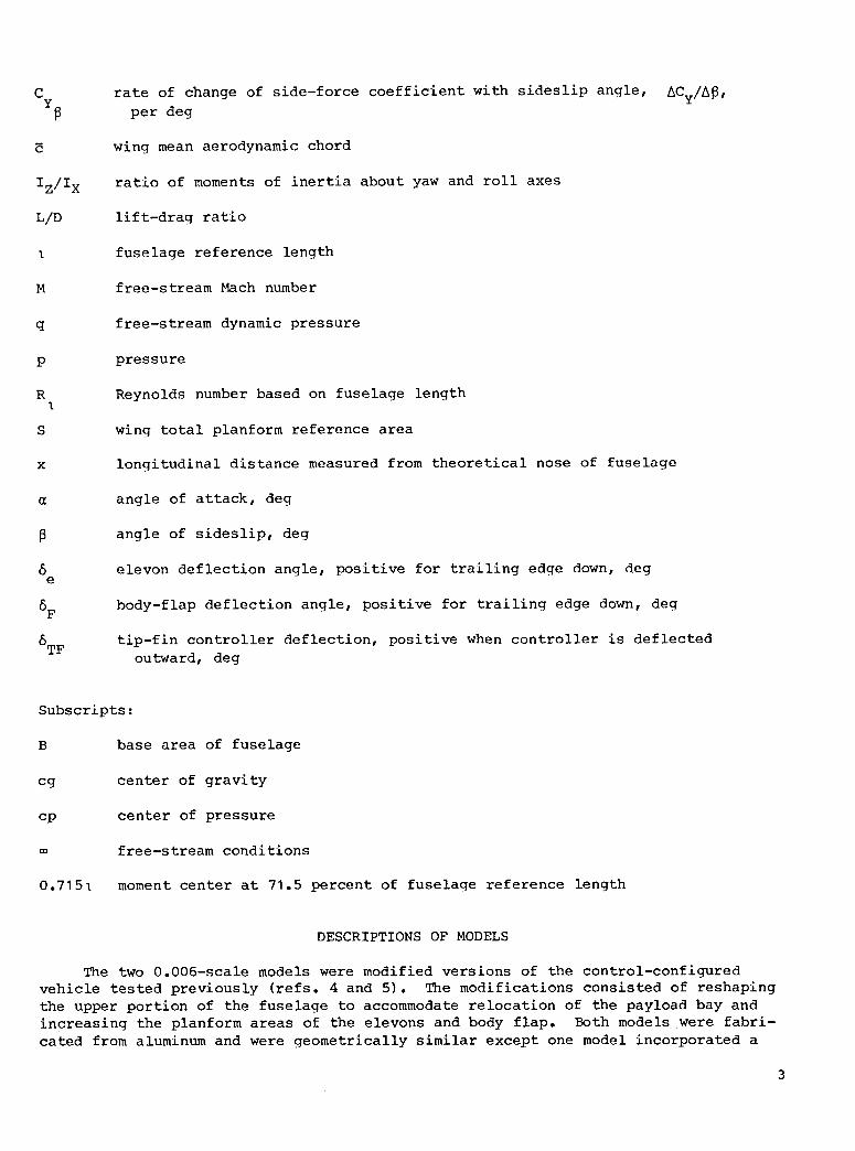
C rate of change of side-force coefficient with sideslip angle, ACy/A_,Y_ per deg
wing mean aerodynamic chord
Iz/Ix ratio of moments of inertia about yaw and roll axes
L/D lift-drag ratio
I fuselage reference length
M free-stream Mach number
q free-stream dynamic pressure
p pressure
R Reynolds number based on fuselage lengthI
S wing total planform reference area
x longitudinal distance measured from theoretical nose of fuselage
angle of attack, deg
angle of sideslip, deg
6 elevon deflection angle, positive for trailing edge down, dege
6F body-flap deflection angle, positive for trailing edge down, deg
6TF tip-fin controller deflection, positive when controller is deflectedoutward, deg
Subscripts:
B base area of fuselage
cg center of gravity
cp center of pressure
free-stream conditions
0.7151 moment center at 71.5 percent of fuselage reference length
DESCRIPTIONS OF MODELS
The two 0.006-scale models were modified versions of the control-configuredvehicle tested previously (refs. 4 and 5). The modifications consisted of reshapingthe upper portion of the fuselage to accommodate relocation of the payload bay andincreasing the planform areas of the elevons and body flap. Both models were fabri-cated from aluminum and were geometrically similar except one model incorporated a
3
single center-line vertical tail and the other had wing-tip fins. (See fig. I.) Themovable outer surfaces of the wlng-tip fins were designed for outward deflections
only. These movable controllers were machined from metal as wedgelike componentssimulating deflection angles of 20° and 40° and were attached to the wing-tip fin bysmall screws. Elevon deflections were set by using pre-bent brackets, whereas body-flap deflections were obtained by using separate interchangeable components for eachdeflection.
Models I and 2 were designated BWVF and BWTF, respectively, where model compo-nents are identified as follows:
B fuselage
W wing
V vertical tail
T tip fin
F body flap
Full-scale dimensions of both vehicles are presented in table I. Photographs of eachmodel mounted in the langley 20-Inch Mach 6 Tunnel test section are shown in figure 2.
APPARATUS AND TESTS
Wind Tunnel
This investigation was conducted in the langley 20-Inch Mach 6 Tunnel which is ablowdown type facility using air as the test medium. The tunnel has a two-dimensional contoured nozzle which is 2.27 m (89.4 in.) long and incorporates a testsection measuring 0.52 by 0.508 m (20.5 by 20 in.). The sting-support system isremotely controlled and can provide an angle-of-attack range from -5° to 50° and asideslip-angle range from 0° to -10°. Stagnation pressures can be varied from0.2 MPa to 3.6 MPa (30 to 525 psia). To prevent liquefaction, the air can bepreheated up to 567 K (560°F) by the use of an electrical resistance heater. Testrun times of 1 minute are possible when the flow exhausts into a vacuum sphere and upto 20 minutes when an annular type air ejector is used. Additional details includingMach number calibrations are presented in reference 6.
Tests
All tests were conducted at a stagnation pressure of 0.689 MPa (100 psia) and atemperature of 453 K (355°F). The average free-stream Mach number was 5.93 at a unitReynolds number of 6.24 × 10⁶ per meter (1.9 x 10⁶ per foot).
Force and moment data were measured by a sting-supported six-component strain-gage balance. Both models were tested over an angle-of-attack range from 0° to 40°in 5° increments at sideslip angles of 0° and -2°. Model attitudes were accuratelyset by using a small prism mounted flush in the fuselage which reflected light from apoint source located near the test section onto a calibration board. Free-streamMach number was determined by using an actuator-mounted pitot probe which was
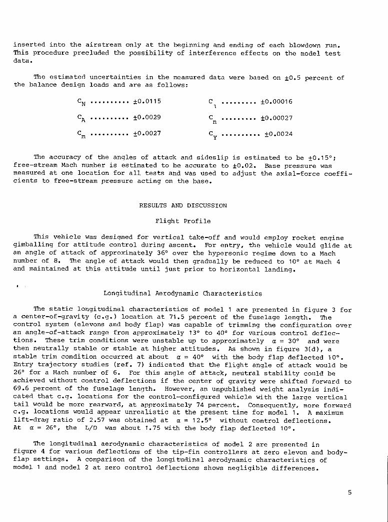
inserted into the airstream only at the beginning and ending of each blowdown run.This procedure precluded the possibility of interference effects on the model testdata.
The estimated uncertainties in the measured data were based on ±0.5 percent ofthe balance design loads and are as follows:
CN .......... ±0.0115 C ......... ±0.000161
CA .......... +0.0029_ C ......... +0.00027n
Cm .......... +0.0027_ Cy .......... _+0.0024
The accuracy of the angles of attack and sideslip is estimated to be ±0.15°;free-stream Mach number is estimated to be accurate to ±0.02. Base pressure wasmeasured at one location for all tests and was used to adjust the axial-force coeffi-cients to free-stream pressure acting on the base.
RESULTS AND DISCUSSION
Flight Profile
This vehicle was designed for vertical take-off and would employ rocket enginegimballing for attitude control during ascent. For entry, the vehicle would glide atan angle of attack of approximately 36° over the hypersonic regime down to a Machnumber of 8. The angle of attack would then gradually be reduced to 10° at Mach 4and maintained at this attitude until just prior to horizontal landing.
I
Longitudinal Aerodynamic Characteristics
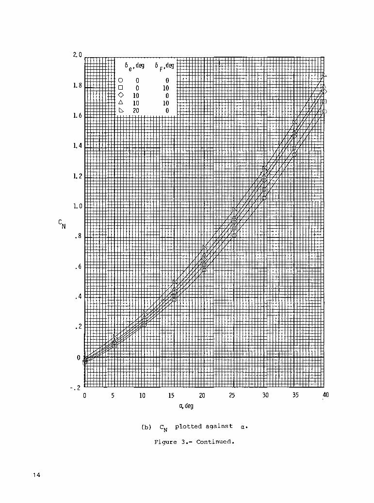
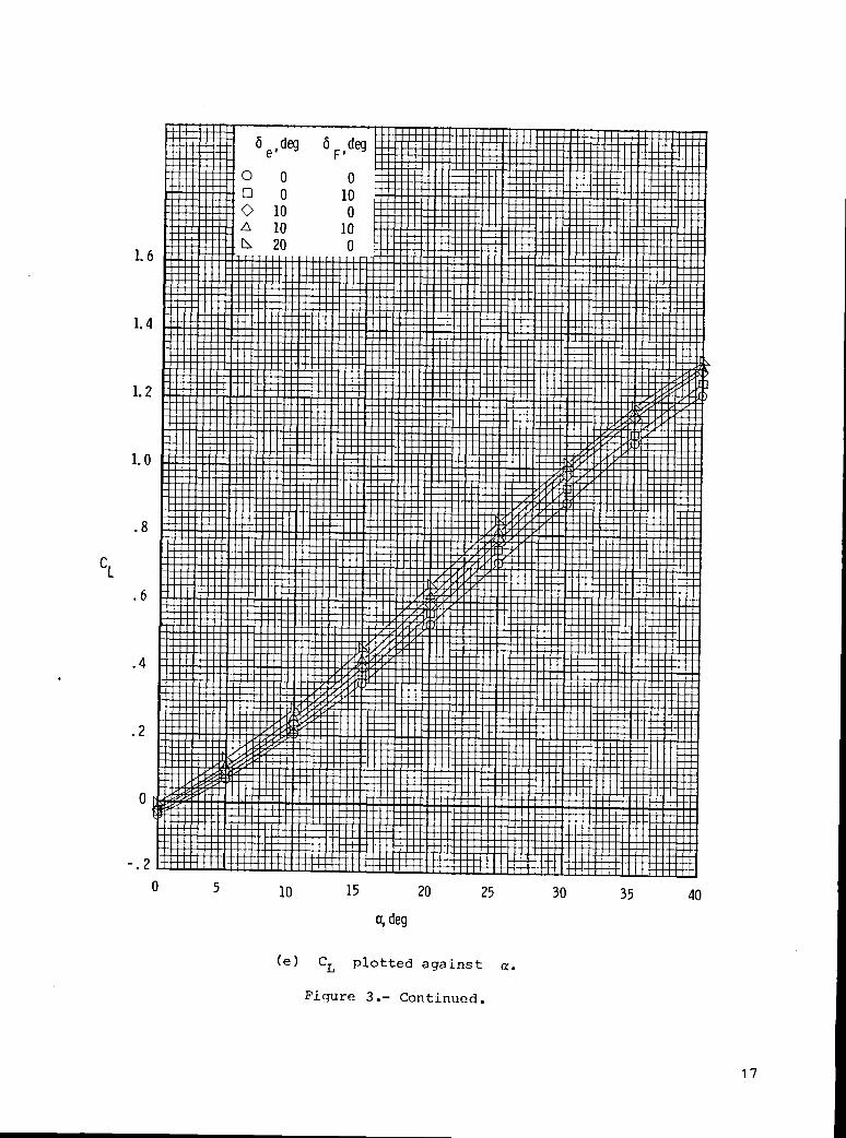
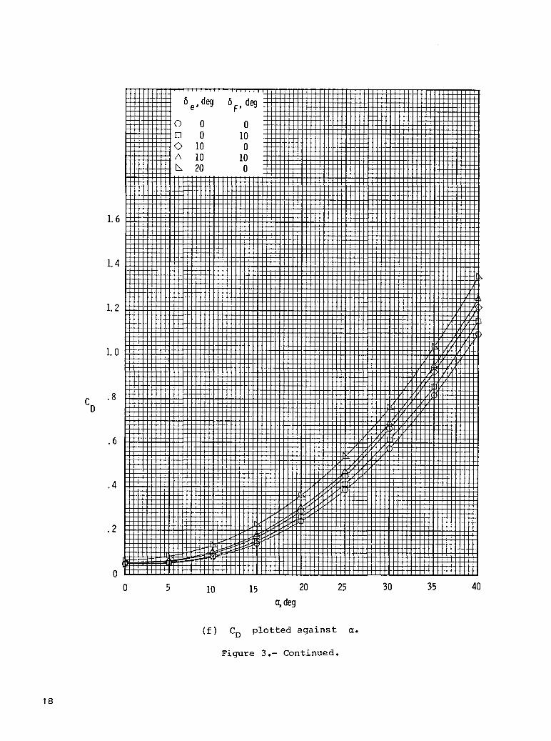
The static longitudinal characteristics of model I are presented in figure 3 fora center-of-gravity (c.g.) location at 71.5 percent of the fuselage length. Thecontrol system (elevons and body flap) was capable of trimming the configuration overan angle-of-attack range from approximately 13° to 40° for various control deflec-tions. These trim conditions were unstable up to approximately _ = 30° and werethen neutrally stable or stable at higher attitudes. As shown in figure 3(d), astable trim condition occurred at about _ = 40° with the body flap deflected 10°.Entry trajectory studies (ref. 7) indicated that the flight angle of attack would be26° for a Mach number of 6. For this angle of attack, neutral stability could beachieved without control deflections if the center of gravity were shifted forward to69.6 percent of the fuselage length. However, an unpublished weight analysis indi-cated that c.g. locations for the control-configured vehicle with the large verticaltail would be more rearward, at approximately 74 percent. Consequently, more forwardc.g. locations would appear unrealistic at the present time for model I. A maximumlift-drag ratio of 2.57 was obtained at _ = 12.5° without control deflections.At _ = 26° , the L/D was about 1.75 with the body flap deflected 10° .
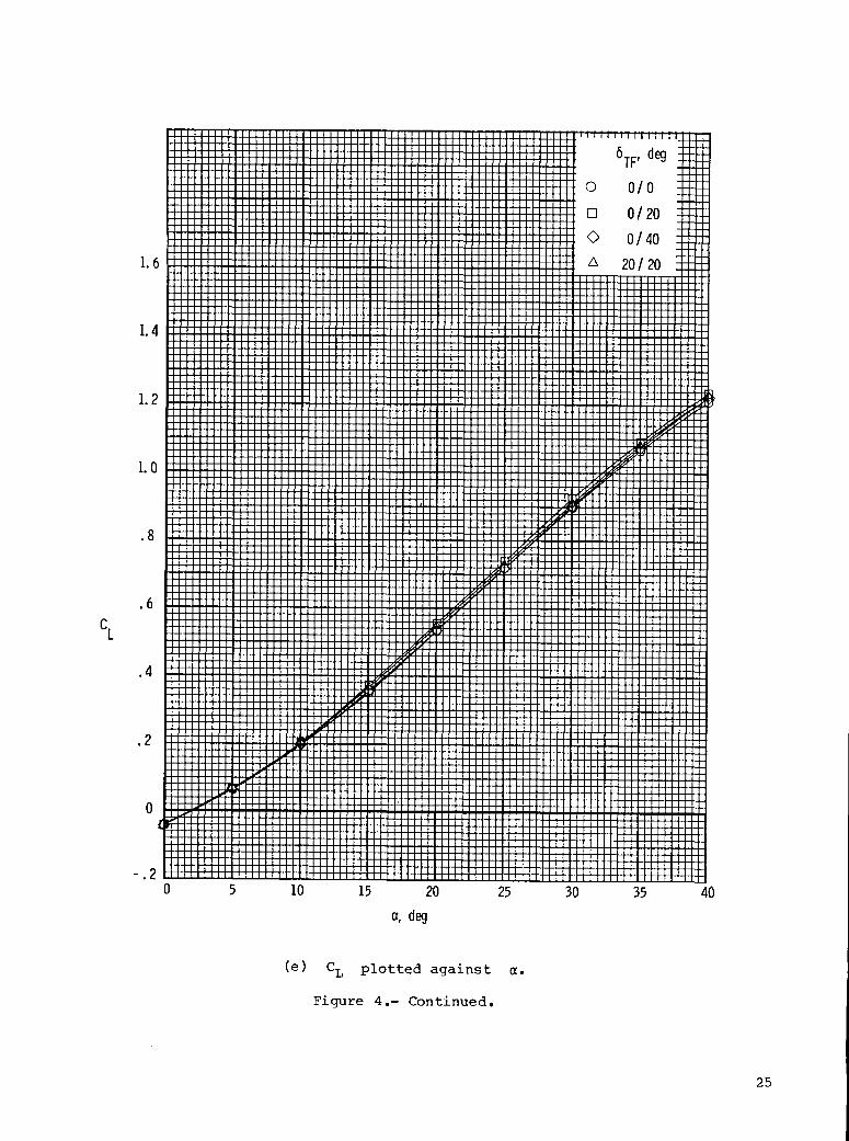
The longitudinal aerodynamic characteristics of model 2 are presented in
figure 4 for various deflections of the tip-fin controllers at zero elevon and body-
flap settings. A comparison of the longitudinal aerodynamic characteristics of
model I and model 2 at zero control deflections shows negligible differences.

Consequently, the previous discussion of stability and control of model I isapplicable to model 2 for the same flight conditions and c.g. location.
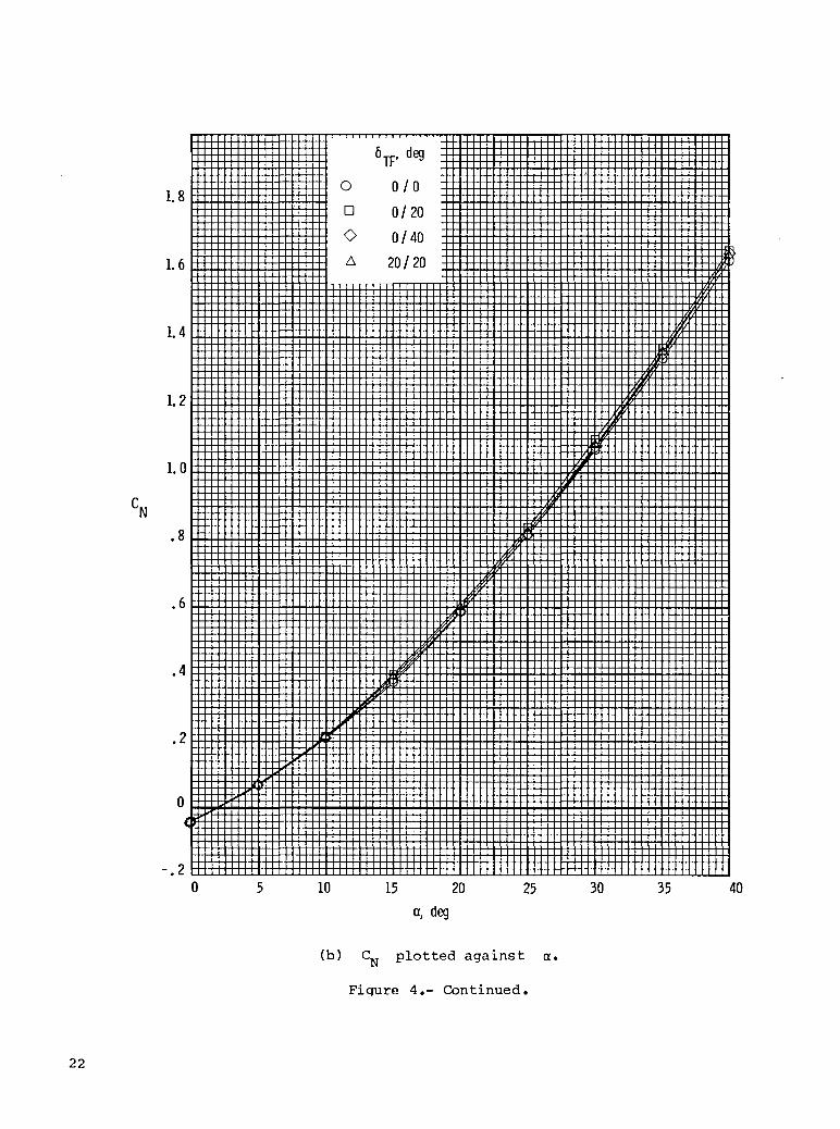
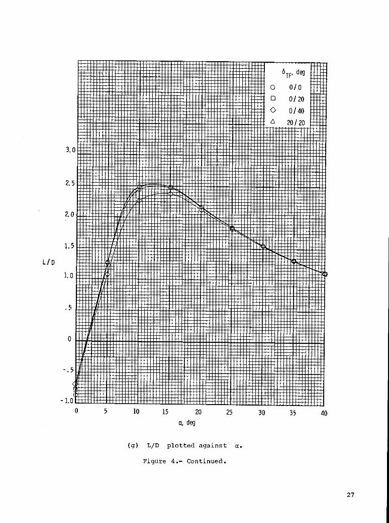
Tip-fin controller deflection had only a small effect on the pitching-momentcoefficient (fig. 4(d)). When the right controller was deflected 40°, C at= 26° changed by only -0.003, which is approximately equal to estimate_ balance
accuracy. An even smaller increment in Cm was measured when both controllers weredeflected 20°. The only appreciable effect of tip-fin controller deflection was onthe maximum values of L/D which occurred at angles of attack from 12.5° to 15°, asshown in figure 4(g). At the operational angle of attack of 26°, the measured valueof L/D was approximately 1.77 for the various controller deflections.
Lateral-Directional Aerodynamic Characteristics
The lateral-directional aerodynamic characteristics of models I and 2 are pre-sented in figure 5 for zero deflections on all controls. The data were obtained atsideslip angles of 0° and -2°. Although both configurations were statically unstableat Mach 5.93, the results showed that removing the rather large center-line verticaltail and adding the smaller wing-tip fins actually slightly increased directionalstability. At angles of attack greater than 8°, both models exhibited positiveeffective dihedral /C h withabout the same levels of magnitude. Favorable
%JI _= were obtained only at higher angles of attack for(positive) values o n_/uyn
both configurations. At the flight angle of attack of 26°, the dynamic directional-stability parameter was zero for the center-line vertical tail configuration andslightly positive for the wing-tip-fin configuration.
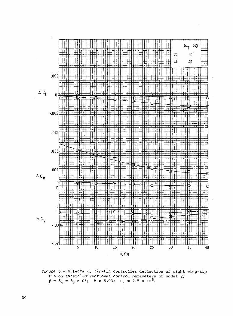
Lateral-Directional Control Characteristics
In figure 6, the effects of tip-fin controller deflection of the right wing-tipfin on roll-, yaw-, and side-force control parameters were determined at zerosideslip. At the operational angle of attack of 26°, the magnitudes of roll- andyaw-control parameters were quite small for a controller deflection of 20°. However,an increase in the deflection to 40° did result in significant roll- and yaw-controlcapability, especially yaw control. At flight conditions, the ratio of AC tonAC of about 5.0 indicates that the wing-tip-fin controller is basically a yaw-control device. In-house calculations using the reaction-control system values fromfigure 1(b) of reference 7 indicate that the wing-tip-fin controller when deflected40° can produce a yawing-moment increment equal to approximately 1.2 yaw jets, or itcan provide a trim capability for a 1° perturbation in sideslip.
CONCLUDING REMARKS
Aerodynamic characteristics of a single-stage-to-orbit vehicle based on control-configured concepts have been obtained at Mach 5.9 in the Langley 20-Inch Mach 6Tunnel. The configuration had a large body for internal fuel and payload and a small50° swept wing. Two vertical-fin arrangements were investigated: a large center-line vertical tail and small wing-tip fins. Longitudinal and lateral-directionalcharacteristics were obtained over an angle-of-attack range from 0° to 40°.

With the center of gravity at 71.5 percent of the fuselage length, the aerody-
namic control system provided longitudinal trim conditions for both configurations
over an angle-of-attack range approximately 13° to 40 ° . _hese trim conditions were
unstable up to approximately an angle of attack _ = 30 ° and were then neutrally
stable or stable at higher attitudes. A stable trim condition was achieved at
= 40 ° with the body flap deflected 10 °. Both configurations had positive
effective dihedral at angles of attack greater than 8° . Directional instability
occurred over the entire angle-of-attack range because of the rearward center-of-
gravity location. At the flight angle of attack of 26°, the dynamic stability
parameter was zero for the vertical tail configuration and only slightlyTn
positive for the wing-tip-fin configuration. Large outward deflections of the wing-
tip-fin controller were effective for yaw control.
Langley Research Center
National Aeronautics and Space Administration
Hampton, VA 23665
November 30, 1982
REFERENCES
1. Henry, Beverly Z.; and Decker, John P.: Future Earth Orbit TransportationSystems/Technology Implications. Astronaut. & Aeronaut., vol. 14, no. 9,Sept. 1976, pp. 18-28.
2. Henry, Beverly Z.; and Eldred, Charles H.: Advanced Technology and Future Earth-Orbit Transportation Systems. AIAA Paper 77-530, May 1977.
3. Hepler, Andrew K.; Zeck, Howard; Walker, William H.; and Shafer, Daniel E.:Applicability of the Control Configured Design Approach to Advanced EarthOrbital Transportation Systems. NASA CR-2723, 1978.
4. Freeman, Delma C., Jr.; and Wilhite, Alan W.: Effects of Relaxed Static Longitu-dinal Stability on a Single-Stage-To-Orbit Vehicle Design. NASA TP-1594, 1979.
5. Bernot, Peter T.: Aerodynamic Characteristics of Two Single-Stage-To-OrbitVehicles at Mach 20.3. NASA TM X-3550, 1977.
6. Goldberg, Theodore J.; and Hefner, Jerry N. (appendix by James C. Emery):Starting Phenomena for Hypersonic Inlets With Thick Turbulent Boundary Layers atMach 6. NASA TN D-6280, 1971.
7. Freeman, Delma C., Jr.; and Powell, Richard W.: Impact of Far-Aft Center ofGravity for a Single-Stage-To-Orbit Vehicle. J. Spacecr. & Rockets, vol. 17,no. 4, July-Aug. 1980, pp. 311-315.
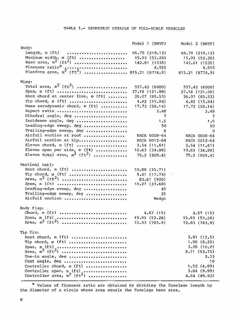
TABLE I.- GEOMETRIC DETAILS OF FULL-SCALE VEHICLES
Model I (BWVF) Model 2 (BWTF)Body:Length, m (ft) ......................... 66.79 (219.12) 66.79 (219.12)Maximum width, m (ft) ................... 15.93 (52.26) 15.93 (52.26)Base area, m2 (ft2) ...................... 142.61 (1535) 142.61 (1535)Fineness ratioa .......................... 4.955 4.955Planform area, m2 (ft2) .................. 815.21 (8774.9) 815.21 (8774.9)
Wing:Total area, m2 (ft2) 557.42 (6000) 557.42 (6000).eooo.ooo.ooeeoeoooeo
Span, m (ft) ............................. 37.18 (121.98) 37.18 (121.98)Root chord at center line, m (ft) ........ 26.07 (85.53) 26.07 (85.53)Tip chord, m (ft) ........................ 4.82 (15.84) 4.82 (15.84)Mean aerodynamic chord, m (ft) ........... 17.72 (58.14) 17.72 (58.14)Aspect ratio ............................. 2.48 2.48Dihedral angle, deg ...................... 7 7Incidence angle, deg ..................... 1.5 1.5Leading-edge sweep, deg .................. 50 50Trailing-edge sweep, deg ................. 0 0Airfoil section at root ................. NACA 0008-64 NACA 0008-64Airfoil section at tip .................... NACA 0012-64 NACA 0012-64Elevon chord, m (ft) ..................... 3.54 (11.61) 3.54 (11.61)Elevon span per side, m (ft) ............. 10.63 (34.86) 10.63 (34.86)Elevon total area, m2 (ft2) .............. 75.2 (809.4) 75.2 (809.4)
Vertical tail:Root chord, m (ft) ....................... 10.88 (35.71)Tip chord, m (ft) ........................ 5.41 (17.74)Area, m2 (ft2) .......................... 83.61 (900)Span, m (ft) ............................. 10.27 (33.68)Leading-edge sweep, deg .................. 45Trailing-edge sweep, deg ................. 25Airfoil section .......................... Wedge
Body flap:Chord, m (ft) ............................ 4.57 (15) 4.57 (15)Span, m (ft) ............................. 15.93 (52.26) 15.93 (52.26)Area, m2 (ft2) 72.83 (783.9) 72.83 (783.9)eeoooo.ooooeoooo.eoe.ooooe.
Tip fin:Root chord, m (ft) 3.81 (12.5)
Tip chord' m (ft) iiiiiiiiiiiiiiiiiiiiiiii 1.90 (6.25)Span, m (ft) .....[ 3.05 (10.0)
Area, m2 (ft2) ... 8.71 (93.75)Toe-in angle, deq 2.33Cant angle, deg .. [_ 10Controller chord, m (ft) ................. 1.52 (4.99)Controller span, m (ft) .................. 3.04 (9.99)Controller area, m2 (ft2 4.64 (49.92)eooooiooooo...o.
a Values of fineness ratio are obtained by dividing the fuselage length bythe diameter of a circle whose area eguals the fuselage base area.
8

--_. 0723
(a) Model I.
Figure I.- Model details. Dimensions are normalized by.referencefuselage length, t.
_D
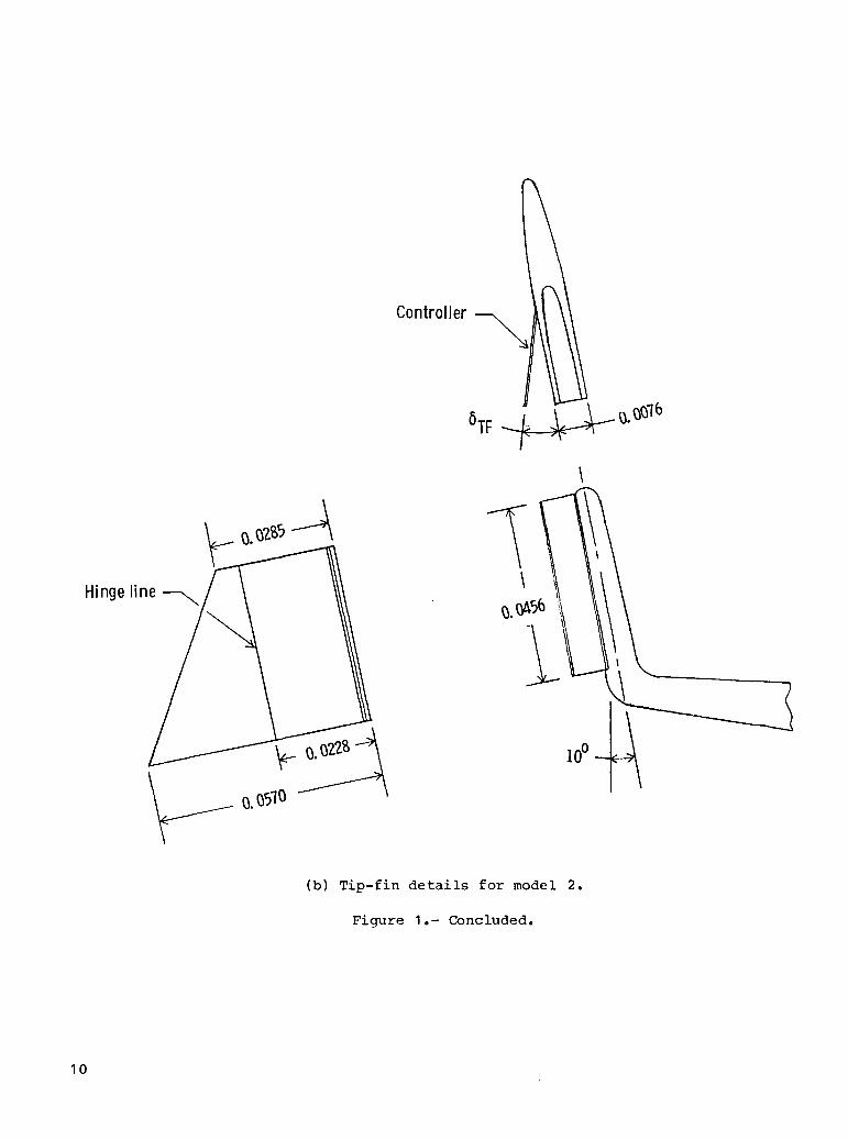
Controller-_
\
Hingeline /
(b) Tip-fin details for model 2.
Figure 1.- Concluded.
10
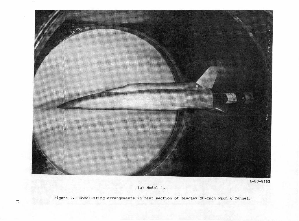
L-80-8163
(a) Model 1.
Figure 2.- Model-sting arrangements in test section of Langley 20-Inch Mach 6 Tunnel.

L-80-8164
(b) Model 2.
Figure 2.- Concluded.

0.696 6e,deg 8 F,deg
0 0 0• 10 [] 0 10
0 lO o10 1020 0
•05
Cm,0.715[
0
-. 05
• 10
-'.15
•20
-.25-.2 0 .2 .4 .6 .8 1.0 1.2 1.4 1.6 1.8 2.0 2.2
CN
(a) Cm plotted aqainst CN.
Figure 3.- Effects of elevon and body-flap deflections on static lonqitudinal aerodynamiccharacteristics of model I. M = 5.93; R = 2.5 × 106.1
2.0
6e,deg
© 01.8 [] 0
10z_ 10F_ 20
1.6
1.4
1.2
1.0
CN
.8
.6
.4
.2
-.20 5 I0 15 20 25 30 35 40
a,deg
(b) CN plottedagainst e.
Figure 3.- Continued.
14

.....8e','ieg.......8['d*'IIIIIIIIIIIiIII'egIIII,IIIiII' ,,,,,,,,,,,,,,,,,IIIIIIIIIIIIIIIIl""'""'""'"
llllllll!!l illl[llill!lllll[
IllI[IIIIill !IIII!IIIIIIIIIII
O 0 0 lllllllllll +I-H-H-I+H+H-FH-I-
o ]o o iiiiiiiiilii'ili'0 [llllllllll Ill IIIII1!IIIIIIIIIIIIIIIIIIIIIIIIIlIII IIllIIIIIIIIIll
r _llr llrT1r IIIIIIIIIII IIIIIIIIIIIIIIIIIllIIIIIIIIIiIIlIIllllIl IIIIIIIIIII IIIIlllIIIIIIII
IIII lll!llllIll llllllIIillllllllllllllllIllFllllI}llllI [lllltlllll,,,,,,,,,,,,,,,,,,,,,,,,, ItlIIIIIII;IIII"lllIlllllllllllllllJlll Jlilllll111 ,,,,,,,,,,,,,,,II lllI[llllII lllllilllIIIIIl
lllIIllIIIIIIIIIIIIIIllIl IllIiillIIl llllIIII!lll !24I+FFFH+I-FFFi-H_H-I-FH_ Illllllllll iIlllIllllIIlo
I!IIIIIIIIIIIIIIIII!IIIII IIIIIIIIIII IIIIIIIIIIIIIIIIIIIIIIIIII IIIIiIIIIIIIIIIIIIIIllllIIIillllllllllll,,,,,,,,,,,
,,Illllll III I Ill ,,,,,,,,,_, ;IIIIII;IIIIIIIlllllllI[ III I ill illIllllll[ lllllllll!illll
201111111111111111111111111,IIlllllIlll ....HH_I+H-H-HH+H-I llIIIIIIIII IIIILI!IIIIIIII
• lllllllllllllllllllllllll,,,,,,,,,,,, +llil-H-illllllllllIIIIIIlllllllllllllIII I lllIlllllll 1III!IIIIIIIIIIllIIIIIIIII I IIIIIIIIIII IIIIIIIIIII?
lllllllllllllllllllllllII'+"["'"" llH,,,,,,,,,_r,.LIIIIIIIIII
IIlllIIIllllIilIIIIIIII!l IIIIIIIIIII --IIIIIIIIIIIIIIIIII{IIIIII IIIIIIIIIII
16 ,,,,,,LHti IrlI_TTTI,,,,,IIIIIIIIIIIIII IIIIIIIII'' II '''>''-_'II,H_• II iJ_'rlilllIIIIIIIIIIIii[llliiiiiiii iiiiiiiitll LA_IIIiIIIIIIIIIIIIIIIIIIIIIIiIIIIIIIIII IIIIIiI!III _'-IIIIIIIIIIIIIIl
lllllllllll_llllIllllllIlIIIII'IIIii _ _ lllllllllIllIllIIlllllllllJllllllllIIll! IIIIIiiiiii II1111111]II111
II{IIIIIIIilIII"III{IIfl,,II{I{IIIIlll_ II,,,_,,,,,,,,,,"'["'"'""L_-LU_'_''IIIII[IIIIIII IIIIl",._ i-I-I-i!Illl'lllIlIIIIIIIIIII ''''''''''+''_ '"_'"'" I i _-.-_l+lllItlllllIl I lJ.-"rl I I I I I I I I I I I ] I I_X-.l_7 1 i I I I I I,llllllllllllllllllllllll J_'rllllllllll, I IIL_,,,iI,,,,[{
iiii iii.i_IlillllllllllllllJlIllllI _ [ llllI_llllIiIiIIIIllli]lllIllllIIIl _ ill._.4.-t-_F'_Vi[l]llll
I_ILIIIIIIIIIIIIiIIIIJ.._ _ lllll]lll,]l _1.-_r]iIllliIl]IiIl08 I-H-H-t-H-_ I II_ IIllIIIIIIIII _;_ llIIIIllIllIIIII• Illll, _LI-NII] lllItIlIIIL._- + _ -. llllllIIIIIlIIII
llIIlllIllltIIL..I---t"_IIII L_IIIJ._I-- l]IIllllillJ_l
_=++-INM_,,,,I_'''''''11III ,_--n,,_,,,_-_,, '""_"_-_IIIIIIf Jllllll I \_ ! Ll--.I-_"f I T 11 I I I l_l---t-'#'-Pr I I TI J 1IIIIlllllllllllllllll!£ +MIilIIIIIIII + IIIIIIlllilllllll
_llllll_'f'Tl-l- .-_'_ ]llllll_lll,, ,,,,.__--.,_-,-_II _ '""I'""III''',_,,_.rIIIII ....
il Iillli i_ll i ' _i "-t--r'TTIIIi_II IIIiii'+111 "''!1111_11 _ _llir"l-Illl!_lllll ;i.04,,,,,,,,,,-,,,,,,,,,_ ..... _ ,,[,,,,,,,,, IIIIIIIIIIii111!t!
I ilillllliill [ ''''''l!lllllllllH+H-t-H_H+,,,,,IIIIIIIIIIIIII , ,,,,,,,,,,1, , .
t-l-i-_+l,,,,,,,,,'_'_'u"'llllllllliillI llllillllill ,' -_ ,_
'""llillilllilllllllill I ,IIIIIIIIIiii '+'"'"'++"'"I|'II,, IIIIII"IIIIIIIII IIIIllllllllllllJl IlllllllJJlll IIILIIII IIIIIII11111 III11!1111111111
I__llllllllllllll lllllllillll IIIIIllIllIIIlllIIllllllllllll IIIIIII!IIII illlllllllllllli........ ,,,,,,,,,,,,,,4 IIIIIIIII!llllilIIIIIII!1111 IIIIIIIIIIIII!11
• I111111111111111111111111 III!11111111 IIIIIII11_!1111iIIIIIIit111111111111111!1 IIIIIIIIIIII IIII111111111111
llllllllllrllllllllIlll I llIlllllllll lIl!llllllllIlll_l-l-__llll Illllll!!l!l I[llllllllllllI!lililllllllllllllllllllll IIIIIIllllll IIIIIIIil1111!11
litzI_LLUL_IIII'IIII"IIII.,, llllllllllll li,,,,_,,+,,,,,l'"'"l_'""'_]llllllillllJlllll i, IlJllllillll
osm+vw_+i_+__ _-_ +,_'-_-+-H-F illlilllliil ill-I iii111 I iii
0 5 I0 15 20 25 30 35 40
deg
(c) CA and CA,B plotted against _.
Figure 3.- Continued.
15

._ IIIIIliilliilll { i, F"+ 6 deg 6 deg i
e' F' {o 0 0[] 0 I0 _ 'O I0 0
-i _.... _ 10 10 I1 _ 20 0 ], I
l[llllllll -" I
fi[llillll II IIIIIIIIIII
IIIIli!lli
15 IIIIIIIIII i• IIIJllllll [
iiiiiii11' I ]IIIIIIIll I I
llll[llll
Iiii}II",, 1 ",,IIIIIII I
.in.+ .IIIIIIIII I IIIIIIIIIII I 11IIIIIIIII I _4--!--
Illlillll " I IIIIIIIIiii
lilllllll ;_ [ 1tllll[llllIIII11111 I II
05 illllilll _> I It" IIIIlllll KIllillill . I lIIIII1111 _ I IIIIIIIIII I I
C IIIII1111 I I
m,0.715[ l:lllllll " 1 '/I 1. _ ..... 111
Illlll _'1
IIIIIIIII . _ _ 1Jlllllll! II I I I I IJ,'_,lj] iF _ i _ '1111_111 P _ '1-- - F J]ll J"glll! _ -,---- F " I II IA'I I I 1_ _-,_ I I
- L.P'I I I I IL + II J,,,-r'l
/ I ] L,4-d-I I I I II. !A_'FIIII]II l
lllllllA_J-J
._. ,_,.._--,_-.,_ _ _..... ,,111111111
•"_ " Iiiiiiiii , "_'!Jlllll_l i l
"T'l--I'-I--t-_r+l]_'_ I_ ] IIIIIIIIII R H'.L. I I
IIIIIIIII .... _ _-.......... 1 1_t .... IIIIIIIII _ _ :-.._ ,' 1
" _ [ IIIIIIIII ! IIIIIIIllll I _ . I1111111111 I _ I
.... Iiiiiiiiii _1'111111111 1_.1
IIIIIIIII tIllllllll
IIIIIIIII I II I-.20 IllllllllIIIIIIII_ 1 1IIIIIIIlll I I
lllll{llll I ],]llli+,Jl i ' I iIIlll[llll I ] I i
-.25 F - -+H-H-HHH-+ ,' ,' ,' _'0 5 i0 15 20 25 30 35 40
deg
(d) Cm plottedagainst e.
Fiqure 3.- Continued.
16
6 e,deg 6 F,deg
© 0 0[] 0 10
10 0ix 10 10I',.20 0
1.6
1.4
1.2
1.0
.8
CL
.6
.4
.2
-.2
0 5 i0 15 20 25 30 35 40
o,(leg
(e) CL plotted against _.
Fiqure 3.- Continued.
17
16
14
12
i0
.8CD
.6
.4
.2
0
0 5 10 15 20 25 30 35 40
% deg
(f) CD plotted against 5.
Figure 3.- Continued.
18

6e,deg 6F,deg
0 0 0[] 0 10<_ 10 0
10 10{h 20 0
3.0
2.5
L/D2.O
1.5
1.0
.5
-.5 _
-i.0
0 5 I0 15 20 25 30 35 40
a,deJ
(g) L/D plotted against _.
Figure 3.- Continued.
19

1.0
'"'""""""' " iiiilj e'd_IIIIIIIIIIZIIlIII 11l II
Illlilllll]lllll] I I:
_lllllllIlllillll i II "".9 _,,'_'"']llJ"l'"" :I] ]',,i:I I O[] 00 I00_,_;::::_:::1::: rj ,,"II,_,,],,,,,,,,,1, ,, : 10 0
III _[ _CV_J"¢,_[[ilI_ I[llllllll]ll |llllllllll[I [I]1 r I
Itllkl N_4.rl_l_r,,4,Jll; L _"_lllllJllll IIilIIIlilIFI IIII tI}lli%l_TrZI]]-,,_ili'-,J-_ ItlT'_llli Illliiilfllli lil]llll_l"l'_lll"'b,-,,L_] _ _'-,,_JIII'--I-_'IF_ _ _lllllllll.lll IIII "_
.7 _,,,,,,,,,,I,,,,,-_-_-_,_,,,,,_,,,;,,ill_;, ,:,_ ,l:llllilillllllll -r'_-_-_'_' _ IIIIIIIIIIIFIFIIII IIIIII I]II
:I::_::::I_::IliillII:I:I:I:III_:,,,,,,,,,, II• IIIIIIll Iltllllllllll IIII il[lllllllllt Ill! Illlllllllllllllll IIIIIIIIIIIII II],,,,,,,,,, ,,,,
IIIIIIIIIIIIIIiii llllll;llllll '"'"'"'"' IIII ,,• ,,,,,,,,,,,,, lllllllllllll _,,, ,,
Xcp/[ I[llll]llilill[IJ IIl[illllllllI[l,lll[l,liliii] IJiJl,lliilll ::::I:I:II:I: :::: [I
'"'""'"'"'" [ il5 lllllil:ll:lllll: l:J]lll]lllll IIIIIIIIIII I :l]l• illLll]|lllll lllFill!]ll I II]1 I
:i;:llllji :::I::II:III_:II, _,,_,,,,,,,,,, ::::::::: :I: :Ill 'FF-H
IIIllll I[ll Ill IIIIlllllllll Illl[lilillil IIII ]
lllllllillllllill lllli_lllllll ll_llllllll|l IIII l• lllllllllllllllll llll[lllllll] "IIIIIIIIIIIII IIII I
IIII I
IIIIIIIIIIIIItI, "'"'" '""
lllllllllliiilHl III'"'"'"' I II "' '"'"'"'"' '"' i3 lllillII I illllllllilll,,,, '• ,,,,,,, III,,, lllllJlllllIl,,,,,,,,,,,,,,,,,,,,,,,,,,,,,,,,,, ,,,,,,,,,,,,, , ,, ,,,, -H-H--H
2 Iiiiii, , iii IIIII]]]]II]] jill]]llll:l:,,,,,,,,,,, ,,,,III] ]'• llqlllltlilll|lll _llllillllll| llllill!lllll fill I
iIIIIIII,IIIIIIIL i,,,,,,,,,,,,,,,,, lllllilllllll lllllilllllll IIIIJllilllllllFIIlll Jlill"'"'" '"'"'"'"' '"'IIIIII11 III I
llllllllill,,,lll IIIIIIIIIIIII IIIIIII}IIIII IIII ,
t II I
1 '"'""'_""'_' '"'"['"_'_ lllllllllll l Ill,• IIIllllllllllllll IIIIIIIIII111
lllllllllllllllll lllllllllllll lllllllllii I IIII IJllllllllllllllll IIIIIllllllll IIIIIllll I Jill I
lllllllllllllltll lllllllllllll llllilllll!!l IIII II 14I! }i '"'"'" ' '"' "llllllJlllltlllll IIIII I II II,,,,,,,,,,,lllllllllllllllll I 11 IJlllllllllll Illl I1o , IIIIIIIIIIIIIIIII iiiii,,,,,,,, IIIIIIIIIIiti IIII II
0 5 lO 15 20 25 30 35 40deg
(h) Xcp/l plotted against _.
Fiqure 3.- Concluded.
2O

•2O
15
10
•05
Cm,0.7151
0
-.05
-.10
(a) Cm plotted against CN-
Figure 4.- Effects of tip-fin controller deflection on longitudinal aerodynamic characteristics
of model 2. 6e = 6F = 0°; M = 5.93; R I = 2.5 × 10⁶ .
Fo
''''''''' ........ I
6TF, deg , iII
1.8 __;...... 0 0/0 I
[] Ol 20 i I1 t
I
0/40 I II
I.6 _ 20/20 '
_ llllllltllllll _"Nt IIIit1111111111 _ IIIItlllltlllll !1 IIIIIIIII1111tl Ih I II11111111!11!1 _ t I
14 '"_'"'"'"' _ I I• Illlllllllllfl I 'Z
IlllllllJiJlll _ I IIii11111111111
Illliillllllll ] IIIlllllllllllll
IIIIIIIIl[llli I IIIII11111111tl ! 1III11111111111 _ I
IIIIIIIit11111 _ IIIIIIIIIIIIIII •lllltllll!llll r
1.2 IIIIIIIIIIIIII 1; 11111111111111 IIlllllllllllt L I 1i IIIIIIIIIIIIII I I
Ill |1111111 I I
1 0 ll,lllllllllll _ IIIIIII111111111 {• llllllllllllllIIII1t11111111 Illllltlllllll! !
CN ,, llllllllltllll 1IIIIIIIIIIIIII : _ 1.8 i:llll:ll :;!tIlllllll]!l I
IIIIIIIIiiiiii IIlllllllllllll II I
ItllllIIIII1",, I II[111lllll]lllIIIIIIIIllllll _ 1
fl
6 llllllllllllll _ ' I• IIIIIIIIIIllll
Illllilillilll _ 11IIIIIII111111_IIIIIIIIIIIIV# I III]IIIIIIIIV!#I I I
.4 IIIIIII_III , ,! "+'_IIIII ' j
I il]l_-/illllllll lI Ilk_"ll[[llllll I
I I_'llillllllll I
J_'ll]lllllllll IIllllltllllll ! i
'vlllllll_Iillll ' I 1,2 :llllll]llltit ] iIItlIIJILIIli i
IIIIIIIIIIitli 1 i i _ 1Illlllll]llll] t i l I
jjs' Itllllllllllli I I I
0 ":+ +L IIIIIIIII11111 Ii "; i I,,IIIIIIIIIIII 1
IIIIIII1111111 I
iiii1111111111 i, illtl!llflllll
I I IIIIIIIIIIIIII i I- 2 ,, 1 lllllllllll'll 1 I• , II
0 5 I0 15 20 25 30 35 40
% d_J
(b) CN plotted against 5.
Fiwure 4.- Continued.
22

IIIIIIIIIIIII ' .......... eqIlllllxllIll, 6TF,: ,,,_(,_,_,,,_ d __IIIIll{llllll
[III11]IIIIIIIIIIIIIII1111 O 0/0
I Iil11111!]111
, [], I , ]ll]lllllllll O 0/40[
ll]l]l![lllll: _liltllil[llll
, 111111111111] A 20/20IlJllilllJJltllJlllillllJi .... iiiiiil I
II Iit1111 {JltlJl] I
= 11 /_ , llillllllllll ,,,,,,, _+ 1.24 IIIIIIIIIIIII ,,,,,,,'"'"'
11111111111tlIIIIIIIIIIIII I111III I
IIi111 I, , llllllJllllll i I,,,,,,Illl!llltllll Illllll /Itll[|ll}]lfl iJt[[i[
I |lllllllll]ll I]il[ll I
|illlllii[lli lllllll ]
•20' ' lllllllllllll IIIIIIIIlllllillllll 1111111
lllliiillllll IIIIIIIII[IIIIIIIIII IIII{II
[I IIIIIIIIIII"I,, IIII,,,
1111 IIIIII IIIIIll i
' '"'"'"'"' lilIItl t]IIIIIIIIIIII ,,,,,,,• ]2 , IIIIIIIIIIIII '"'_" t,,, IIIIIII
" II "i IIIIIIIr: llltt ii' !'"'"'""" ]lllfll 1cA , ,, {iillll!!!!!l .......... ,,, lllll!i :.08 L lli:lllllllil '""IIIllll
IIIIIIIIIIIII IIIIIII 'Illlllllillll III1111 i
I IIII111111!111 IIIILII III11t111!11!1 IIIII11
_ --:--7 ! _, ,., t 11JMIS.LLI I : : _ . _ ff ....... ""1 IIII IT'III I I_._, I --. Itlllllllllll I lilllll [
i III!!lllillll I
llllillll;lll / iiii[ll[i # l[tlli4=lltllll _ ! . I_1
0 lll'"'llllll,,,, _rt-t-t-_l'f-_ --i-_IIIIIIIIIIIII llllLll IIIIII"]IIIII """' 1I |1,,H,,,,,,,,, IIIIIII ,
I lllllllllllll: llll"ll, 1,,,,,,,,,,,,, ,,,,,,, ,IIIIIIIIIIIII
04 "- [iiliillll,ll lil t-t_t I• 1
lllillllll"l,, I!IIHI ..... _II11tlt111111 I
IIIIIIIII]III i I !,:l,,,I ,I- II I llllllllIIIIIIIIIIII1! I I I1
.08H-I i' 1_ r IIlI"I-H-I"I ' ' ' HIIIIII '-- l I I I 1II
0 5 10 15 20 25 30 35 40
a, deg
(c) CA and CA,B plotted against _.
Figure 4.- Continued.
23

IIIIIIIiiii..............-"'_'''''" 6TF,deglilllJlllll
lllllilllll
,_, ,, , 0 0/0 -II{!lllltllliillllilII
I111 -- i
lllllll,,,, E_ 0120Jlttllli::l
'"""'"' 0 0140 - i
IlllllllllllllililIlll
IIIIIIl[IIl A 20120 -lll{lll[llllilllilllll 1 II Tt_T,,,,,,lJ,,, ,111lll{lllilll IIII
:IIIIII:I:I I:I:IIIIIII1111
lllll[[llll IIIIIIIIII11111 llIl
:I:::I[:II: i:l:IIIIIl!llll IIII IIllllll!lll IIII Illilllillll IIII I
IIII I
llllllill!l IIll IIIIIIIfllll IIII
•20 IIIIIII:III , :III iIll I
Illilltiill IIIt iIIIIt IIII
lll:llllll: :III Illlllllllll Jill I
•15 :IIIIII:::: IIII II!ll|[fllll I111 I
IIIIl[lllll f!llI1111111111 IIII
Cm,0.715[ i III l lllllI I I I I I I I I L.,b,._ _ :1 IlilIII]_-"'J_F _ II]l I
] IIl_ll IIII ;II L.,J'J_I'lWr[lllll |III
.05 _--'R"T,fillIIll fillb_ Illllllllll • IIII ,'
I _ IIIIIII1111 I IIII, . ,,,,,,,,,,,,,,,,,,,,I IIIIII fill
..... , ::I:;!;:II'IIii illllll]llll IIII :
,. lllillllll, :IIillllIIIllll i I
illllllllll IIllI IIIIIllllll
i. _ I:I:IIII::I II:I11111111111 till# IIIIIIlIIIi III1"1 I i
-.05 _ , • , _l]llil,ll] IIII_"''''_ II111111111 IIIi
; lllIl[ll'lll llllIllIIIIIII fill
lllllril[ll IltlI1|11111111 IIII• IIIIIIIIIII IIII
10! I liilil,l,t, I111-. , IFH-IIIIIII IIII: :lllllllil: 1::::
I i IIi::1{II:I IIIIi i l I1111111!11 IIII
I i I I!lllllllll IIIII Illllllllll IIII ,II 1 IIIIIIIIII1 I, I111
15 _- , I I-. , lllllllllll II I111II I111
0 5 10 15 20 25 30 35 40
_ d_
(d) Cm plotted against _.
Figure 4.- Continued.
24
IIIIIIIIIIIIIIIIIIIII I f- ' ....... '""! )"llllllllllllllllll,, TF'IIIIiii1111111111111,,,,,,,,,,,,,,,,,,,,,IIIIIIIIIIIIIIIIII11 0 0/0,,,,,,,,,,,,,,,,,
Ilillllllllllllllllll
11111111'1111111'"11',, ,, _ 0/40IIII
1.6 )1111111111111111)IIIIII"III"IIIIIII,,,, r,,,,,,,,III111"III"IIIII{I ,,,,,,_,, IIII II tlllllllll(lllltllillllllilll)illtl IIIl[l[illli!lil
IIIIII"III"IIIIIII,,,, IIIIIIIIIIIIIIIIlllllllllllll(lllll IIIl(lllmlllllli
1.4 ((l("((((((If_("((,,,, '"'"'""'"".-[llll}l(lllllll(llll,,,,,,,o,,,,,,,,,,,, IIIIIIIIIIIIIIIIllllllllll)llll[llll III[IiIIIIiIIIIIilllll#llllllllllll!
IIIIIIIIIIIIIIIIII11 IIIIIIIIIIIIIIIIililtlil[lllllli
1.2 lll(ll|lllilllllllll I
fllll(lllllll((lI(ll ,III({111111 ,,,_-',,_..l(llillllllllll[llll l Ill[lllillliJ_-/(IIllill(llillll(llll( I Iiillllll{i_l¢_/lll
IIIIIIIIIIIIIIIIIIII 1 IIIIII"_III,,_._,,IIlllllll(lllllilllt ! IIIIIIL_IIIlllIlltllilllllllllilli i llilJ[/X--//'l'[il(ll!
1.0 l)((lillllllI))l((l) [ ll"_,i{)(iill,._,,llllilil(lltll((}lll (L4/X/llill(llllilIIIlillltll(ll)lllil L4_FI
'("I(("(((I({{(II{(,,,, _-,,IIIIIII111{I]_Jrlll[ll(lllllllliltlllll(llllll(llll I (illlll{llrl(lll
_ lllIll(lllllllllllll ........ . _ °IIIIIIIIIIIIIIIIIilllill(ll(ll[lllll % lilillll(llilll)l
.8 (llilllill(llll)l)() " 1111111111111)I)1lll)lil)llllIlllllll , llllllllIlllllll'Ilili I[lilllllllll(
11 lllllliilllllilll((llilllll) lilllllml(Ilillilili!li(llltll IlilillllllilltlIlllilllllllllllltll i IIl|llllll]ili!l
6 IIIIIIIIIII11[111t11 _ ,• - ,,,,,,,,,,,,,,,,,,,, ,, llllllilllllllllIIIiiiiiiiiiiiiiiiii _ Iiiiiiiiiiiiiiii
eL Imlllillllllllll[;ll Illllllllll[lllltliltlllilllll[l|lll [
. I11111)1111111111111 _ II11111111111111t1111111111111111111 _ II[]lIllllllllll
4 IIIIIII1111111111111 _ IIIIIIIIIIIIIItll _o
Illllillllllll[lllll _ _ lillilllllllllllllltlllltlllllllllll t I IIII!11111111111
IllllllllillllllIIIIIIIIIIIIIIIIIID_ • I ,,,,,,,,,,,,,,,_tllllllltllllllllLii_ Illllllllllllll}
IIIIIIIIIlll[lll
illlllllllllll.iPlllll I (l]lllllll[lllllIIlll(ll(lllll(lll
Illlllllll_il_]lllltl Illl]llllllill(I
IIIIIII'_""IIII111_..,,,, 1 lllllllI'IIlllll,,,I i L_I,..,_,,IIIIIIIIIIIIIII i
IIIlll!lllllillll
0 "'llllllllilllllllllll I I !+H-_HIIIIIIITIIIIIIIIIIII(IIIII(II [IIIIIIIIIIIIIII
lllll[lllllllllllilllllllilllll IIIIII,,,,,_,,,,III111111111111111111
...... IIIIIIIIIit1111111111 IIIIIIIIIiii1111,,1,,,,,,,,1,1,,,,,,; llllllllllllllll
-.2 I)111111(1(1111111111 ' l)((ll(lll(lll((• 0 5 10 15 20 25 30 35 40
a, deg
(e) CL plotted against _.
Figure 4.- Continued.
25

I ',, 6TF,degI
o o/o[] 0120
o/40
1.8 A 20/ 20I1111111!11 I1llllilllIIl II
I:lllllllIlII' IIlllllllIl 1
IIIIIIIIIII II
1.6 IIIIII"III,,,,'*IIlllllllll I,] Iill[llllIl II
|IIIttttItlI Ii lll!lll]lllll
lllllIllIIl I
llllIlllllI,-H1.4 llllllllllll I
_ _ IIIIII"III,, IIltlltllllll:lIIllIlllIIII I]IIIIIIIIIII I
, IllIIIlfllll!lllllIlllIllllIIIlllIIlliII!IIIIIIIIIIlIII
1 2 ,llIiIIIIII I• tlltl!lllll ItIIlllllllII IIIIIIIIlllll tl
IIIIIIIIIII III _ IIIIIIIIIII II' IIIlll"llI,, _.II IIIIIIIIIII _1
1.0 I ' iiiiii"iii,, _1 i[IllIllll_l
[ IIIIIIIIIIK/I I,,"llllllIJ11 I'j llrllrllJ/lllll
IIIII *-_,_,II 1.8 -, "-*IIIIt.i i , iJlI,_VIIIIII
I I III_YIIIIIII I1
' ,' II/PI,II"III,,,II YI,IFIIIIIIIlI| l
l_IIIiLlliIII I,1 _I= _ ,llllIlllllI
IIIIIIIIIII I
.6 i llllllIllll, t' iiiiiii!!!!!:lI "1
II
[ _ . _ IIIIII IIII. IIIIIIIIIIllI • : IllllIllllll I
.4 _, llIIIII''
r_ IIIIIIitl I"_ _ IIl[l!lll I
_ Illllllll I• _ iiiiiiiiii Illllllllll IIIII111111 I IllllIllIll 1 I
0 I IIIIIIIIII' I0 5 i0 15 20 25 30 35 40
a, deg
(f) CD plotted against 5.
Figure 4.- Continued.
26
30
20
1,5
L/D
1.0
(g) L/D plotted against e.
Figure 4.- Continued.
27

(h) Xcp/l plotted against e.
Figure 4.- Concluded.
28

•002
C
0
0
Cnp
-.002
•OO5
o
-.005
0 5 I0 15 20 25 )0 35 40%deg
Figure 5.- Lateral-directional aerodynamic characteristics of models 1 and 2.
6e = 6F = 6TF = 0°; M = 5.93; R I = 2.5 x 10⁶.
29
o
-.002
.012
.008
.004
o
o
-.01
-.02o 5 10 15
a, deg
20 25 30
0TF' deg
o 20
o 40
35 40
30
Figurefin
~ =
6.- Effects of tip-fin controller deflectionon lateral-directional control parameters ofo = of = 0°; M = 5.93; R = 2.5 x 10 6 •e \
of right wing-tipmodel 2.


1. Report No. 2, Government AccessionNo. 3. Recipient's Catalog No.NASA TM-84565
4. Title and Subtitle 5. Report Date
EFFECT OF MODIFICATIONS ON AERODYNAMIC CHARACTERISTICS January 1983
OF A SINGLE-STAGE-TO-ORBIT VEHICLE AT MACH 5.9 6. PerformingOrganizationCode506-51-I3-02
7. Author(s) 8. Performing Organization Report No.
Peter T. Bernot L-15504
10. Work Unit No.
9. Performing Organization Name and Address
NASA Langley Research Center 11 ContractorGrantNo
Hampton, VA 23665
13. Type of Report and Period Covered
12. Sponsoring Agency Name and Address Technical Memorandum
National Aeronautics and Space Administration 14. Sponsoring Agency CodeWashington, DC 20546
15. Supplementary Notes
16. Abstract
Hypersonic stability, control, and performance characteristics have been determinedon a single-stage-to-orbit vehicle based on control-configured stability concepts.The configuration (0.006-scale model) had a large body with a small 50° swept wing.
Two vertical-fin arrangements were investigated which consisted of a large center-line vertical tail and small wing-tip fins. The wing-tip fins had movable surfaces
called controllers which could be deflected outward. Longitudinal and lateral-directional characteristics were obtained over an angle-of-attack range from 0°to 40°. The effects of tip-fin controller deflection on roll- and yaw-controlcharacteristics at a sideslip angle of 0° were obtained. This investigation wasconducted in the Langley 20-Inch Mach 6 Tunnel.
17. Key Words (Suggested by Author(s)) 18. Distribution Statement
Hypersonic stability and control Unclassified - UnlimitedEntry vehicle aerodynamics
Advanced space transportation systems
Subject Category 02
19. Security Classif. (of this report} 20. Security Classif. (of this page) 21. No. of Pages 22. Price
Unclassified Unclassified 31 A03
Forsale by theNationalTechnicalInformationService,Springfield,Virginia 22161NASA-Langl ey, 1983


NationalAeronauticsand THIRD-CLASS BULK RATE Postage and Fees Paid r A _
SpaceAdministration National Aeronautics andSpace Administration
Washington, D.C. NASA-45120546
Official Business
Penalty for Private Use, $300
III lIE "_X " POSTMASTER: If Undeliverable (Section 158Postal Manual) Do Not Return