napier city council code of practice for … · demonstrate compliance with chapter 66 of the...
TRANSCRIPT

NAPIER CITY COUNCIL
CODE OF PRACTICE FOR
SUBDIVISION & LAND
DEVELOPMENT
PARTS D to M
DESIGN AND CONSTRUCTION
-A MEANS OF COMPLIANCE
July 2015

View over Napier – photograph courtesy of Peter Scott

Napier City Council JULY 2015 i
CONTENTS
D. CODE OVERVIEW ................................................................................................................. D-1
D.1. GENERAL OVERVIEW ................................................................................................................................ D-1
D.2. DESIGN CRITERIA AND CONSTRUCTION STANDARDS OVERVIEW ............................... D-1
E. EARTHWORKS ........................................................................................................................ E-3
E1. EARTHWORKS: DESIGN ............................................................................................................................ E-3
E1.1. INTRODUCTION ................................................................................................................ E-3
E1.2. RELEVANT STANDARDS AND GUIDELINES ...................................................................... E-3
E1.3. GEOTECHNICAL SITE INVESTIGATIONS ........................................................................... E-3
E1.4. STORMWATER CONTROL ................................................................................................. E-4
E1.5. SUBSOIL DRAINAGE .......................................................................................................... E-5
E1.6. MASS EARTHFILLS ............................................................................................................ E-5
E1.7. FILL DENSITIES .................................................................................................................. E-6
E1.8. FILL BATTERS .................................................................................................................... E-6
E1.9. CUT BATTERS ................................................................................................................... E-6
E1.10. BLENDING OF BATTERS .................................................................................................... E-6
E1.11. BATTER SURFACE PROTECTION ...................................................................................... E-6
E1.12. RELATIVE HEIGHT OF ROADS AND LOTS ........................................................................ E-6
E1.13. SMALL SCALE EARTHWORKS ........................................................................................... E-7
E2. EARTHWORKS: CONSTRUCTION ........................................................................................................ E-8
E2.1. EARTHWORKS – GENERAL ................................................................................................ E-8
E2.2. RELEVANT STANDARDS AND GUIDELINES ...................................................................... E-8
E2.3. APPLICATION OF SPECIFICATIONS .................................................................................. E-9
E2.4. UNEXPECTED CONDITIONS .............................................................................................. E-9
E2.5. GEOTECHNICAL MONITORING OF EARTHWORKS .......................................................... E-9
E2.6. STORMWATER DRAINAGE AND SILT CONTROL .............................................................. E-9
E2.7. DUST CONTROL ............................................................................................................. E-10
E2.8. EXCAVATION .................................................................................................................. E-11
E2.9. CONSTRUCTION OF FILLS .............................................................................................. E-11
E2.10. COMPLETION OF EARTHWORKS .................................................................................... E-12
E2.11. EARTHWORKS CONSTRUCTION REPORT....................................................................... E-13
E2.12. AS BUILTS AND COMPLETION DOCUMENTATION ........................................................ E-13
F. ROADING ............................................................................................................................... F-15
F1. ROADING DESIGN .................................................................................................................................... F-15
F1.1. INTRODUCTION .............................................................................................................. F-15

Napier City Council JULY 2015 ii
F1.2. RELEVANT STANDARDS AND GUIDELINES .................................................................... F-15
F1.3. ROAD SAFETY AUDIT ..................................................................................................... F-16
F1.4. CLASSIFICATION OF URBAN ROADS.............................................................................. F-16
F1.5. CLASSIFICATION OF RURAL ROADS .............................................................................. F-18
F1.6. ROAD STANDARDS ......................................................................................................... F-19
F1.7. PAVEMENT STRUCTURAL DESIGN ................................................................................. F-34
F1.8. SURFACING DESIGN ....................................................................................................... F-36
F1.9. TRAFFIC SERVICES DESIGN ............................................................................................ F-36
F1.10. ROAD LIGHTING DESIGN................................................................................................ F-36
F1.11. MATERIALS ..................................................................................................................... F-38
F1.12. NON-PUBLIC ACCESSWAYS FOR OTHER THAN FRONT LOTS (Urban & Rural) ............ F-39
F1.13. CAR PARKING ................................................................................................................. F-43
F2. ROADING – CONSTRUCTION ............................................................................................................ F-44
F2.1. GENERAL ......................................................................................................................... F-44
F2.2. RELEVANT STANDARDS AND GUIDELINES .................................................................... F-44
F2.3. SUBGRADE CHECKING .................................................................................................... F-45
F2.4. SUBBASE .......................................................................................................................... F-45
F2.5. BASECOURSE ................................................................................................................... F-45
F2.6. PAVEMENT DEFLECTIONS .............................................................................................. F-45
F2.7. ROAD SURFACING .......................................................................................................... F-45
F2.8. FOOTPATHS .................................................................................................................... F-46
F2.9. KERB AND CHANNEL AND DISH CHANNELS ................................................................. F-46
F2.10. VEHICLE CROSSINGS ...................................................................................................... F-47
F2.11. BERMS AND TREES.......................................................................................................... F-47
F2.12. TRAFFIC SERVICES, ROAD FURNITURE, BENCHMARKS ................................................. F-48
F2.13. ROAD LIGHTING ............................................................................................................. F-50
F2.14. INSPECTION AND TESTING ............................................................................................ F-50
F2.15. AS BUILTS AND COMPLETION DOCUMENTATION ........................................................ F-50
G. WATER SUPPLY ................................................................................................................... G-51
G1. WATER SUPPLY – DESIGN .................................................................................................................... G-51
G1.1. INTRODUCTION ............................................................................................................. G-51
G1.2 RELEVANT STANDARDS AND GUIDELINES ................................................................... G-51
G1.3 APPROVALS .................................................................................................................... G-51
G1.4 GENERAL REQUIREMENTS ............................................................................................. G-51
G1.5 DESIGN STANDARDS ..................................................................................................... G-52
G1.6 DESIGN PRESSURES ........................................................................................................ G-52
G1.7. WATER DEMAND AND FIRE FLOWS .............................................................................. G-54

Napier City Council JULY 2015 iii
G1.8. MAIN SIZING .................................................................................................................. G-54
G1.9. STANDARD PIPE SIZES ................................................................................................... G-54
G1.10. RETICULATION LAYOUT ................................................................................................ G-55
G1.11. PIPE SUPPORT AND ANTI-SCOUR BLOCKS ................................................................... G-57
G1.12. THRUST BLOCKS ............................................................................................................ G-57
G1.13. FIRE HYDRANT LOCATION ............................................................................................ G-57
G1.14. VALVE LOCATION .......................................................................................................... G-58
G1.15. SERVICE CONNECTIONS (includes connections for Fire Sprinkler Systems) ............. G-58
G1.16. STORAGE ....................................................................................................................... G-61
G1.17. SUPPLY PUMPS ............................................................................................................... G-62
G1.18. COVER OVER MAINS AND SERVICE PIPES ..................................................................... G-62
G1.19. MATERIALS .................................................................................................................... G-63
G1.20. WATER SUPPLY – NON RETICULATED AREA................................................................. G-70
G2. WATER SUPPLY – CONSTRUCTION ................................................................................................ G-72
G2.1. GENERAL ........................................................................................................................ G-72
G2.2. SETTING OUT ................................................................................................................. G-72
G2.3. INSPECTIONS BY THE COUNCIL’S REPRESENTATIVE ................................................... G-72
G2.4. TRENCHING ................................................................................................................... G-72
G2.5. CONTROL OF WATER .................................................................................................... G-73
G2.6. MATERIAL CONDITION ................................................................................................. G-73
G2.7. RETENTION OF WATER SUPPLY FLOWS ........................................................................ G-73
G2.8. PIPE LAYING, JOINTING AND BACKFILLING .................................................................. G-73
G2.9. SERVICE CONNECTIONS ................................................................................................ G-74
G2.10. TESTING ......................................................................................................................... G-74
G2.11. SURFACE BOXES ............................................................................................................ G-76
G2.12. DISINFECTION, DECHLORINATION AND DISPOSAL ..................................................... G-76
G2.13. CONNECTIONS TO CITY SUPPLY .................................................................................. G-77
G2.14. AS BUILTS AND COMPLETION DOCUMENTATION ....................................................... G-77
H. WASTEWATER ..................................................................................................................... H-79
H1. WASTEWATER – DESIGN ..................................................................................................................... H-79
H1.1. INTRODUCTION ............................................................................................................. H-79
H1.2. RELEVANT STANDARDS AND GUIDELINES ................................................................... H-79
H1.3. APPROVALS .................................................................................................................... H-79
H1.4. DESIGN AND FLOW REQUIREMENTS ............................................................................. H-80
H1.5. STRUCTURAL DESIGN .................................................................................................... H-80
H1.6. PIPE SUITABILITY AND PROTECTION ............................................................................ H-81
H1.7. SEWAGE PUMPING STATIONS AND PRESSURE MAINS .................................................. H-81

Napier City Council JULY 2015 iv
H1.8. LOCATION OF WASTEWATER MAINS ............................................................................ H-87
H1.9. CONNECTIONS .............................................................................................................. H-88
H1.10. ACCESS CHAMBERS ....................................................................................................... H-89
H1.11. DESIGN PARAMETERS .................................................................................................... H-90
H1.12. PIPE DESIGN ................................................................................................................... H-90
H1.13. MATERIALS .................................................................................................................... H-91
H1.14. INFILTRATION CONTROL .............................................................................................. H-94
H1.15. ON LOT TREATMENT AND DISPOSAL OF HOUSEHOLD WASTES ................................ H-94
H1.16. WASHDOWN FACILITIES ................................................................................................ H-96
H2. WASTEWATER – CONSTRUCTION .................................................................................................. H-97
H2.1. GENERAL ........................................................................................................................ H-97
H2.2. SETTING OUT ................................................................................................................. H-97
H2.3. TRENCHING ................................................................................................................... H-97
H2.4. CONTROL OF WATER .................................................................................................... H-98
H2.5. CONTROL OF WASTEWATER FLOWS ............................................................................. H-98
H2.6. PIPE CONDITION ............................................................................................................ H-98
H2.7. PIPE LAYING AND JOINTING.......................................................................................... H-98
H2.8. JOINTING PIPES .............................................................................................................. H-99
H2.9. PIPE CONTAMINATION .................................................................................................. H-99
H2.10. CONNECTIONS .............................................................................................................. H-99
H2.11. ACCESS CHAMBER CONSTRUCTION ............................................................................. H-99
H2.12. INLET AND OUTLET STRUCTURES .............................................................................. H-100
H2.13. COUNCIL INSPECTIONS ............................................................................................... H-100
H2.14. TRENCH BACKFILLING AND SURFACE REINSTATEMENT ........................................... H-100
H2.15. INSPECTION AND TESTING OF WASTEWATER MAINS ............................................... H-100
H2.16. TESTING OF ACCESS CHAMBERS ................................................................................ H-101
H2.17. AS BUILTS AND COMPLETION DOCUMENTATION ..................................................... H-101
I. STORMWATER ................................................................................................................... I-103
I1. STORMWATER – DESIGN ..................................................................................................................... I-103
I1.1. DESIGN PHILOSOPHY ................................................................................................... I-103
I1.2. RELEVANT STANDARDS AND GUIDELINES .................................................................. I-104
I1.3. APPROVALS ................................................................................................................... I-105
I1.4. MINIMUM PROTECTION CRITERIA ............................................................................... I-105
I1.5. STORMWATER QUALITY ............................................................................................... I-106
I1.6. FLOOD ATTENUATION ................................................................................................. I-107
I1.7. CATCHMENTS ............................................................................................................... I-107
I1.8. OPEN DRAINS, NATURAL WATERCOURSES AND OVERLAND FLOWS ......................... I-107
Napier City Council JULY 2015 v
I1.9. STORMWATER RUNOFF CALCULATIONS ..................................................................... I-108
I1.10. RAINFALL INTENSITIES ................................................................................................. I-109
I1.11. DESIGN OF PIPED DRAINS AND CULVERTS ................................................................. I-109
I1.12. OPEN CHANNELS .......................................................................................................... I-111
I1.13. BACKFLOW EFFECTS ..................................................................................................... I-111
I1.14. ACCESS CHAMBERS ...................................................................................................... I-111
I1.15. SUMPS ........................................................................................................................... I-112
I1.16. LOCATION OF STORMWATER MAINS .......................................................................... I-113
I1.17. STRUCTURAL DESIGN ................................................................................................... I-114
I1.18. STORMWATER PUMPING .............................................................................................. I-114
I1.19. STORMWATER CONNECTIONS ..................................................................................... I-115
I1.20. SUBSOIL DRAINS ........................................................................................................... I-116
I1.21. MATERIALS ................................................................................................................... I-116
I1.22. RURAL STORMWATER - PARTICULAR REQUIREMENTS ............................................... I-120
I1.23. WASHDOWN FACILITIES ............................................................................................... I-121
I2. STORMWATER – CONSTRUCTION ................................................................................................. I-123
I2.1. GENERAL ....................................................................................................................... I-123
I2.2. SETTING OUT ................................................................................................................ I-123
I2.3. TRENCHING .................................................................................................................. I-123
I2.4. CONTROL OF WATER ................................................................................................... I-124
I2.5. PIPE CONDITION ........................................................................................................... I-124
I2.6. PIPE LAYING AND JOINTING......................................................................................... I-124
I2.7. JOINTING PIPES ............................................................................................................. I-124
I2.8. PIPE CONTAMINATION ................................................................................................. I-125
I2.9. CONNECTIONS ............................................................................................................. I-125
I2.10. ACCESS CHAMBER CONSTRUCTION ............................................................................ I-125
I2.11. INLET AND OUTLET STRUCTURES ............................................................................... I-126
I2.12. COUNCIL INSPECTIONS ................................................................................................ I-126
I2.13. TRENCH BACKFILLING AND SURFACE REINSTATEMENT ............................................ I-126
I2.14. TESTING OF ACCESS CHAMBERS ................................................................................. I-126
I2.15. TESTING OF STORMWATER MAINS .............................................................................. I-126
I2.16. AS BUILTS AND COMPLETION DOCUMENTATION ...................................................... I-127
J. RESIDENTIAL SUBDIVISIONS ....................................................................................... J-129
J1. DESIGN FOR RESIDENTIAL SUBDIVISIONS OF UP TO THREE LOTS .......................... J-129
J1.1. GENERAL ....................................................................................................................... J-129
J1.2. EARTHWORKS ............................................................................................................... J-129
J1.3. PRIVATE WAYS, FORMED ACCESS LOTS, DRIVEWAYS ................................................ J-129

Napier City Council JULY 2015 vi
J1.4. LOCATION OF SERVICES .............................................................................................. J-129
J1.5. UTILITY SERVICES – URBAN ......................................................................................... J-130
J1.6. UTILITY SERVICES – RURAL .......................................................................................... J-131
J1.7. SOLID WASTE MANAGEMENT ...................................................................................... J-131
J1.8. OTHER FACILITIES ........................................................................................................ J-131
J2. DESIGN FOR MULTI-STOREY BUILDINGS / APARTMENT COMPLEXES .................... J-132
J2.1. WATER SUPPLY ............................................................................................................. J-132
J2.2. SEWERAGE ..................................................................................................................... J-132
J2.3. STORMWATER ............................................................................................................... J-132
J2.4. REFUSE DISPOSAL FACILITIES ...................................................................................... J-132
J2.5. MAIL BOXES .................................................................................................................. J-132
K. UTILITY SERVICES .......................................................................................................... K-133
K1. CABLE SERVICES .................................................................................................................................... K-133
K1.1. INTRODUCTION ........................................................................................................... K-133
K1.2. RELEVANT STANDARDS .............................................................................................. K-133
K1.3. ELECTRICAL, TELECOMMUNICATION & INFORMATION CABLING DESIGN ............... K-133
K1.4. RETICULATION ............................................................................................................ K-133
K1.5. PLANT .......................................................................................................................... K-134
K1.6. ACCEPTANCE OF CABLING ......................................................................................... K-134
K2. GAS RETICULATION ............................................................................................................................ K-135
K2.1. INTRODUCTION ........................................................................................................... K-135
K2.2. RELEVANT STANDARDS .............................................................................................. K-135
K2.3. RETICULATION ............................................................................................................ K-135
K2.4. PLANT .......................................................................................................................... K-135
K2.5. ACCEPTANCE OF GAS RETICULATION ....................................................................... K-135
L. PARKS, RESERVES AND SPORTSGROUNDS .......................................................... L-137
L1. GENERAL ..................................................................................................................................................... L-137
M. APPENDICES ..................................................................................................................... M-139
M1. AS-BUILT INFORMATION REQUIREMENTS ............................................................................. M-141
M1.1. AS-BUILT PLANS .......................................................................................................... M-141
M1.2. WATER SUPPLY CONNECTIONS ................................................................................. M-142
M1.3. SEWER CONNECTIONS ............................................................................................... M-142
M1.4. STORMWATER CONNECTIONS ................................................................................... M-143
M1.5. ROADING AS BUILT PLANS ......................................................................................... M-143
M1.6. COMPLETION DOCUMENTATION .............................................................................. M-144
M1.7. AS-BUILT ADDITIONAL INFORMATION ...................................................................... M-147
M2. STANDARD DETAILS – ROADING ............................................................................................... M-155

Napier City Council JULY 2015 vii
M3. STANDARD DETAILS – SEWERS AND STORMWATER ....................................................... M-157
M4. STANDARD DETAILS – WATER SUPPLY ................................................................................... M-159
M5. STANDARD FORMS: ROADING .................................................................................................... M-161
M6. DRAUGHTING SYMBOLS AND CODES ...................................................................................... M-163
M7. GLOSSARY OF STANDARDS / GUIDANCE NOTES ............................................................. M-165
M8. SUBJECT INDEX ..................................................................................................................................... M-167


CODE OF PRACTICE FOR SUBDIVISION Part D – Code
AND LAND DEVELOPMENT Overview
Napier City Council JULY 2015 D-1
D. CODE OVERVIEW
D.1. GENERAL OVERVIEW
The Napier City Council Code of Practice for Subdivision and Land Development
(The Code), sets the standard for subdivision or land development within the
Napier City Territorial area.
Parts A, B, and C, (under separate cover), set out mandatory requirements for
resource management, and minimum levels of engineering performance and
standard, for all aspects of subdivision and land development, as required by the
Napier City Council.
Part A - describes the Management Strategy and Rules for Subdivision and
Land Development, Procedures and Requirements relating to Resource
Consent Applications, Assessment Criteria, and information on
Inspection regimes and Statements of Professional Opinion.
Part B - describes the objectives and performance criteria that all
infrastructural elements need to achieve.
Part C – identifies the minimum requirements for infrastructural design
and construction.
All aspects of Parts A, B, and C must be satisfied for subdivisions and land
development projects to be approved.
Parts E – M, provides a means of compliance to the obligatory requirements of
Parts A, B, and C.
Parts E to L deal with the requirements for earthworks, roading, water
supply, wastewater, stormwater, residential subdivision, utility services,
and parks, reserves & sportsgrounds.
Part M (Appendices) provides information regarding as-built
requirements, infrastructural standard details, and general information
on Standards, and includes a Subject Index.
In using this document, the following criteria shall apply:-
All levels shall be in terms of Hawkes Bay Local Authority Datum 1972
(MSL = 10.0 metres).
All references to drawings relate to drawings contained in Part M, unless
stated otherwise.
All diameters shown are nominal diameter.
D.2. DESIGN CRITERIA AND CONSTRUCTION STANDARDS OVERVIEW
This Code of Practice comprises both technical specifications and general
methods which may be applied in the design and construction of Subdivision
and Land Development.
The Design Criteria for the Code is found in sub-part 1 of Parts E – L.
Construction Standards required by the Code are located in sub-part 2 of Parts E
– L.

CODE OF PRACTICE FOR SUBDIVISION Part D – Code -
AND LAND DEVELOPMENT Overview
Napier City Council JULY 2015 D-2
Both parts are non-statutory and do not form part of the District Plan. They set
out acceptable design and construction standards which, if satisfied, will
demonstrate compliance with Chapter 66 of the District Plan – “Code of Practice
for Subdivision & Land Development Parts A, B and C”.
The details as outlined are Napier City Council’s minimum requirements, and are
based on nationally recognised standards. They are not the only means of
compliance. Where considered appropriate, alternative design methods may be
used provided they achieve the requirements contained in Parts A, B and C, the
Code of Practice for Subdivision and Land Development.
CODE OF PRACTICE FOR SUBDIVISION Part E1 – Earthworks -
AND LAND DEVELOPMENT Design
Napier City Council JULY 2015 E-3
E. EARTHWORKS
E1. EARTHWORKS: DESIGN
This section should be read in conjunction with Chapter 52A “Earthworks”
of the City of Napier District Plan, which addresses objectives, policies and
methods relating to earthworks associated with land development.
E1.1. INTRODUCTION
Earthworks for all land and infrastructure development shall be designed to
ensure stable and environmentally acceptable land forms and safe, stable
platforms for buildings, roads and network utility services.
E1.2. RELEVANT STANDARDS AND GUIDELINES
The following is a selection of relevant standards and related documents. The
list is not exclusive and other appropriate standards and guides currently
accepted by the engineering profession may be used. The latest revision dates
for standards, are listed in Appendix M7.
(a) NZS 4402: “Methods of testing soils for civil engineering purposes”.
(b) NZS 4431: “Code of practice for earthfill for residential development”.
(c) New Zealand Building Code Clause B1, B1/VM4 and B1/AS4.
(d) Wellington Regional Council “Erosion and Sediment Control Guidelines
for the Wellington Region” 2002.
(e) Auckland Regional Council Technical Publication No 90: 1999 “Erosion
and Sediment Control: Guidelines for Land Disturbing Activities in the
Auckland Region”.
(f) Auckland Regional Council Technical Publication No 10: 2003
“Stormwater Treatment Devices: Design Guideline Manual”.
(g) NZTA Technical Advice Note TNZ/F1: Specification for Earthworks
Construction.
E1.3. GEOTECHNICAL SITE INVESTIGATIONS
E1.3.1. Predevelopment Report
After the development of preliminary earthworks plans, and prior to any detailed
planning or design, a suitably qualified geotechnical engineer, engaged by the
Design Co-ordinator, shall undertake a preliminary evaluation of the general
nature and character of the site. The evaluation shall be undertaken to
determine the likely requirements for earthworks, any need for further
investigations into the suitability of foundation conditions, and the stability of
the natural ground. The evaluation shall identify any geotechnical testing or
analysis required to confirm the suitability of the site for the earthworks
proposed. Any such testing or analysis shall be carried out under the control of
a suitably qualified person and, where appropriate, the testing laboratory shall
have a recognised registration or quality assurance qualifications.

CODE OF PRACTICE FOR SUBDIVISION Part E1 – Earthworks -
AND LAND DEVELOPMENT Design
Napier City Council JULY 2015 E-4
The report shall be submitted with the subdivision consent application and shall
address relevant issues which may include:
The results of the preliminary investigation,
The results of the geotechnical testing or analysis,
Batter slopes, fill types and compaction specifications
Subsoil drainage requirements.
The extent of unsuitable materials and how they are to be treated or
disposed of.
Materials to be used as fills, their suitability for the subject fills and any
special requirements for their use as fills to achieve the required
strengths and densities.
Confirmation that a suitable stable building site will be available on each
lot along with a feasible and stable access drive, of grade as specified in
Part F1.12.
Where the building site proposed does not satisfy the requirements of
“good ground” (NZBC B1/AS4) a description of feasible founding methods
necessary to enable a building to be built on the site shall be included in
the report.
The stability of the entire site, and its expected performance under the
seismic conditions considered.
When using a scala penetrometer the following information will need to
accompany the results:-
(a) A representative bore log.
(b) A note as to whether the soil is cohesive or cohesionless and the
maximum soil particle size.
(c) A comment on settlement when soft soil is encountered.
E1.3.2. Geotechnical Design Report
For purposes of Engineering Approval, and as part of the development of
detailed design drawings, detailed geotechnical investigations and analysis shall
be carried out, where these are identified as being necessary, in the
Predevelopment Report, or where they are considered necessary to address
issues arising during the detailed design.
The geotechnical design report shall detail all investigations carried out, the
conclusions reached and requirements for the detailed design and construction.
The above report shall be accompanied by a statement of ‘professional opinion’
as to the suitability of the land for subdivision and including any specific
requirements or conditions (see Chapter 66 of the District Plan – Appendix A6).
E1.4. STORMWATER CONTROL
Where natural drainage paths are to be interfered with by the proposed land
development, sufficient alternative drainage facilities shall be provided to the
standards required by Part I, (Stormwater), of this Code. Natural springs and
seepage shall be located and catered for in the design.

CODE OF PRACTICE FOR SUBDIVISION Part E1 – Earthworks -
AND LAND DEVELOPMENT Design
Napier City Council JULY 2015 E-5
All works shall be designed to allow for adequate drainage and silt control
during the construction phase and the post construction phase. The Regional
Council guides referred to in section E1.2 describe minimum standards for the
control of stormwater, erosion and sedimentation on earthworks projects.
Confirmation is required from the Hawke’s Bay Regional Council (HBRC) that the
discharge of stormwater is in conformity with the HBRC Regional Plan. An
erosion control plan shall be submitted as part of the engineering plan approval,
prior to the commencement of earthworks.
E1.5. SUBSOIL DRAINAGE
Subsoil drainage systems shall be provided in valley floors and in other
situations where required to intercept groundwater and minimise problems of
soil piping, softening and reduction in stability. Drains shall be sized to cope
with anticipated flows and superimposed loads.
E1.6. MASS EARTHFILLS
E1.6.1. Mass Earthfill Design
The formations to be constructed shall be suitable for residential development.
In particular, attention shall be given to slope stability, drainage, minimising
differential settlement, aesthetic values, and how the fill may perform under
seismic conditions.
E1.6.2. Plans
The extent of mass earthfills shall be clearly defined in the design
documentation, and shall include plans and drawings, including appropriate
contours and cross sections, showing:
(a) The extent of cut and fill, batter slopes and heights and the extent and
nature of all subsoil drainage systems.
(b) The pre-existing contours including the extent of upstream or
downstream catchments affected by the earthworks.
(c) Details of all culverts including alignment sizes and type of culverts,
inlet and outlet details. These shall include details of temporary or long
term silt control or runoff attenuation where required.
E1.6.3. Specification
The design shall include a construction specification covering earthworks
standards, materials, testing methods to be used, and the systems of quality
checking to be employed.
As a minimum, the specification shall include:
(i) Standards for preparation of the existing ground and removal of
unsuitable materials.
(ii) Standards for placing and control of the fill including control of the
quality of the fill material being used.
(iii) Compaction standards and moisture content control.
(iv) Control of finished levels and position, including batter slopes and
compaction.

CODE OF PRACTICE FOR SUBDIVISION Part E1 – Earthworks -
AND LAND DEVELOPMENT Design
Napier City Council JULY 2015 E-6
E1.7. FILL DENSITIES
The following requirements shall apply unless superseded by any compaction
standards specified by the geotechnical report:
(a) Compaction of the road subgrade layer shall comply with TNZ F/1.
Subgrade is defined as that layer of material in the top 1.0 metre of the
construction measured down from the underside of the subbase course
in both cut and fill situations. Note that cut areas may require
undercutting to ensure uniform subgrade construction.
(b) For all other fills the compaction achieved shall comply with NZS 4431
(refer to clauses 7.4.2.1 and 7.4.3.2).
E1.8. FILL BATTERS
Slopes for fill batters of height greater than 0.5 metres shall be as specified in
the Geotechnical Design Report.
To allow for maintenance, fill batters shall be not steeper than two horizontal to
one vertical.
E1.9. CUT BATTERS
Where slopes are more than 2.5 metres high, steeper than 220
(2.5 horizontal to
1 vertical), and where cuts are 1-2.5 metres or higher, then slopes for cut batters
shall be specified in the Geotechnical Design Report.
Cut batters should be sloped depending on the type of country and materials
involved, however, slopes shall generally be no steeper than ½ horizontal to 1
vertical, and preferably 1 to 1 or flatter.
Benches should be provided as for fill batters above.
The top or toe of a cut batter shall be at least 2 metres from a boundary or
building. The toe of a cut batter shall also be at least 1 metre from the kerb face
or back edge of any footpath but additional allowance may be required to be
made for sight distance on a curve or where a high or low level path is required.
Cut batters shall not be higher than 2.5 metres.
E1.10. BLENDING OF BATTERS
Cut and fill batters shall be rolled over at the top to blend as well as possible
with the natural land contour.
E1.11. BATTER SURFACE PROTECTION
Appropriate batter surface protection shall be provided as described in Section
6.3 of NZS 4431. All batters within actual or designated legal road shall be re-
vegetated in accordance with TNZ F/1.
E1.12. RELATIVE HEIGHT OF ROADS AND LOTS
All new lots shall be able to be drained to the stormwater outlet provided.
Where the kerb is the outlet the lot shall be at a level that provides the required
drainage and cover to pipes.
All lots shall have a level defined as the flood level of a storm having a 2%
probability of occurring annually.
CODE OF PRACTICE FOR SUBDIVISION Part E1 – Earthworks -
AND LAND DEVELOPMENT Design
Napier City Council JULY 2015 E-7
New lots shall be designed to allow for adequate stormwater drainage that
avoids the likelihood of damage or nuisance by the discharge from the
developed area in a storm having a 10% probability of occurring annually.
All new sections shall be formed with sufficient crossfall to the road boundary to
facilitate stormwater run-off, and prevent surface water ponding on the section.
Unless approved otherwise, all new sections shall have a minimum crossfall of
0.6% towards the road boundary.
In all cases, sections shall be shaped so that no surface water flows across
adjacent section boundaries.
For all new and reconstructed roads there shall be no surcharge above sump
grates for a storm having a 10% probability of occurring annually. For roads
where this cannot be achieved an alternative design is required.
For all new roads and roads being reconstructed, ponding on roadways shall be
limited to 300 mm above the grate at sumps for a storm having a 2% probability
of occurring annually. For roads where this cannot be achieved an alternative
design is required. (Section I1.4.2(d))
E1.13. SMALL SCALE EARTHWORKS
For earthworks involving cuts less than 2.5 metres height on sites or hillsides
with slopes of less than 2.5 horizontal to 1 vertical (220
), or fills less than
0.5 metres depth in areas of known soil conditions, Geotechnical Design Reports
are not required.
Cut and fill standards shall comply with the requirements of this Code and the
necessary certification shall be provided on completion of construction.
CODE OF PRACTICE FOR SUBDIVISION Part E2 – Earthworks -
AND LAND DEVELOPMENT Construction
Napier City Council JULY 2015 E-8
E2. EARTHWORKS: CONSTRUCTION
This section should be read in conjunction with Chapter 52A “Earthworks”
of the City of Napier District Plan, which addresses objectives, policies and
methods relating to earthworks associated with land development.
E2.1. EARTHWORKS – GENERAL
All earthworks shall be carried out to the levels, positions and batter slopes
detailed on the approved drawings so as to provide stable land of the form
intended by the design. Methods used shall be appropriate to achieve the
geometric and compaction standards required by the design and relevant
controlling codes and standards.
This work shall include where relevant:
Clearing, including removal of all vegetation and obstructions within the
earthworks limits;
Construction of temporary and permanent silt retention dams, run-off
controls and erosion control devices;
Stripping and stockpiling of topsoil within the earthworks limits;
Preparation of fill areas including benching, removal of unsuitable
materials, and subsoil drainage;
Excavation of all cuts, including subgrade undercutting;
Carting, placing and compacting the excavated material in bulk fills and
road subgrades;
Carting to waste of cut materials unsuitable for use in fills;
Preparation of subgrade areas for road construction;
Trimming final surfaces to shape, re-spreading topsoil and grassing, and
maintenance of the works for the required period.
All of the above works shall be in accordance with the drawings and
specifications.
E2.2. RELEVANT STANDARDS AND GUIDELINES
The following is a selection of relevant standards and related documents which
shall be used where applicable. The list is not exclusive and other standards
and guides accepted by the engineering profession at the time may be used
where appropriate.
(1) NZS 4402: Methods of Testing Soils for Civil Engineering Purposes
(2) NZS 4431: Code of Practice for Earthfill for Residential Development.
(3) TNZ F/1: Specification for Earthworks Construction
(4) TNZ F/2: Specification for Pipe Subsoil Drain Construction
(5) New Zealand Building Code Clause B1, B1/VM4 and B1/AS4
(6) Wellington Regional Council “Guidelines for Silt Control Associated with
Mass Earthworks” revised 1987.
CODE OF PRACTICE FOR SUBDIVISION Part E2 – Earthworks -
AND LAND DEVELOPMENT Construction
Napier City Council JULY 2015 E-9
(7) Auckland Regional Council Technical Publication No 90: March 1999
“Erosion and Sediment Control: Guidelines for Land Disturbing Activities
in the Auckland Region”.
(8) Auckland Regional Council Technical Publication No 10: 2003
“Stormwater Treatment Devices: Design Guideline Manual”.
(9) NZTA Research Report No. 131 “Provisional Guidelines for Erosion and
Sediment Management during Roadworks”.
(10) NZTA Research Report No. 132 “Provisional Guidelines for
Environmental Management during Roadworks”.
E2.3. APPLICATION OF SPECIFICATIONS
The construction of all bulk fills shall be carried out in accordance with NZS
4431 and this Code.
The construction of road subgrades shall be carried out in accordance with TNZ
F/1.
All other aspects of the earthworks, including temporary works to control
erosion and siltation, shall be carried out in accordance with the Contract
Specification and this Code and its associated guides and specifications.
E2.4. UNEXPECTED CONDITIONS
Where conditions exposed on opening up the land are different from those
envisaged during design, the Construction Co-ordinator shall report to the
Design Co-ordinator who shall review the design and modify and adapt the
design as necessary. The Council shall be advised of such situations and design
modifications shall be fully documented and submitted for approval prior to
recommencing work on the affected areas.
E2.5. GEOTECHNICAL MONITORING OF EARTHWORKS
The control of moisture content and compaction of fill material, the accurate
laying of cut and fill batters, and silt control are the most important aspects of
bulk earthworks projects. To ensure proper control of the works the
Construction Co-ordinator, through an experienced geotechnical engineer, shall
monitor the works and carry out adequate inspections and testing to enable a
proper evaluation of the standard of the works and to prepare a report as to the
compliance of the works with the specification. The geotechnical engineer shall
be fully familiar with previous reports and the project specification.
Where necessary, work shall be stopped until the geotechnical engineer has
completed such tests as are required, and has authorised continuation of work.
In the event of any test results not meeting the specified standards, further
compaction or other appropriate remedial action to the satisfaction of the
geotechnical engineer shall be carried out until the desired strengths, void ratios
and/or densities are achieved.
E2.6. STORMWATER DRAINAGE AND SILT CONTROL
Adequate drainage and silt control shall be provided during construction. A
discharge consent may be required from the Hawkes Bay Regional Council for

CODE OF PRACTICE FOR SUBDIVISION Part E2 – Earthworks -
AND LAND DEVELOPMENT Construction
Napier City Council JULY 2015 E-10
the discharge of stormwater from the site while the earthworks are being carried
out.
The surfaces of all cuts and fills shall be kept adequately drained at all times.
Temporary drains and ditches shall be dug to remove water from the surface
during and on completion of the work. All temporary drains shall be maintained
in a clean and tidy condition so that they function satisfactorily until the works
are taken over by the Council.
All necessary interception devices and settlement traps shall be constructed
taking all reasonable steps to prevent the deposition of silt or other deleterious
material on land outside the earthworks area by the action of water or any other
cause. Such facilities shall be maintained during the works and until such time
as the land becomes stabilised to the satisfaction of the Council. Any damages
within or outside the earthworks area caused by inefficient or insufficient
drainage or any other reasons shall be made good by the developer.
The requirements of any resource consent shall be complied with.
E2.7. DUST CONTROL
The best practical means shall be employed to ensure that windblown dust and
soil and associated wind erosion is minimised during and following the
earthworks operations. Dust can be a specific problem in Hawke's Bay due to a
combination of fine silts and strong winds (particularly westerlies).
The developer shall prevent, remedy or mitigate by suitable means to the
satisfaction of the NCC the discharge of dust emanating from the construction of
the works. The developer shall be responsible for ensuring that the Principal,
adjacent residents, property owners or other members of the public, suffer no
undue inconvenience or hardship from dust arising from the works during the
course of the project.
(a) Fixed water spraying.
(b) Water spray trucks.
(c) Screen cloth fences.
(d) Re-grassing or covering cut and fill earthwork areas.
(e) Hydro seeding.
(f) Limiting construction work and disruption through individual properties
to the shortest practical time.
(g) Washing/cleaning of trucks before entry onto public roads.
(h) Stopping construction activities and vehicular movement that raise dust
during strong wind periods.
(i) Cleaning and removal on a regular basis material off sealed roads that
give rise to dust.
Dust control activities shall not be limited only to periods of active construction
but shall be available on a seven-day, twenty-four hour basis for the duration of
the project. On that basis the developer shall supply a contact name and phone
number for both working, and out-of-hours callouts. The developer shall be
CODE OF PRACTICE FOR SUBDIVISION Part E2 – Earthworks -
AND LAND DEVELOPMENT Construction
Napier City Council JULY 2015 E-11
responsible for dust control from the action of all activities on the site including
those of subcontractors and/or service authorities that enter the site.
Site management is the key to dust control, and proactive steps should be
taken to ensure adequate dust control measures are implemented at all times.
Repeated failure to adequately control dust will result in appropriate action
being taken by the Construction Co-ordinator to prevent recurrence.
E2.8. EXCAVATION
E2.8.1 Cut Batters
Cut batters and benches shall be laid accurately to line and level.
Survey position checks shall be made at the position of each bench or in 8 metre
vertical height steps whichever is the more frequent. At no point shall cut
batters deviate from design position by more than ±300 mm. Where such
deviations have occurred measures shall be taken to adjust positions by
adjustment of bench width rather than steepening of batters. If the error is
large the batter top may need to be repositioned in which case consequential
adjustment will need to be made to land areas and facilities at the top of the
batter. In this situation the Design Co-ordinator shall be recalled to review the
changes required.
The edges and top of cut batters shall be rounded to minimise sudden changes
of contour where the batter abuts the natural contours.
E.2.8.2 Slips
Should any earth fall or slip occur in the batter of any cutting or fill either during
or after excavation but before the completed work has been vested in Council,
the Construction Co-ordinator shall arrange for the removal of the material
brought down by such an earth fall or slip, and to make good the damage
caused, to the satisfaction of the Council.
The Design Co-ordinator should be advised of any earth fall or slip.
E.2.8.3 Explosives
If the use of explosives is necessary, blasting operations and the storing of
explosives shall be carried out in compliance with the appropriate laws, bylaws
and regulations.
E2.9. CONSTRUCTION OF FILLS
E2.9.1. Protection of Existing Structures
Any utility service or other structure located under a proposed fill or
embankment shall be protected during the earthworks construction.
Any utility service or other structure located during the earthworks operation
which is not shown on the plans shall be reported to the Council’s Works Asset
Department immediately.
Any damage to any pipeline or other structure shall be made good to the
standards required by Council’s Works Asset Department or the utility operator
responsible for the structure.

CODE OF PRACTICE FOR SUBDIVISION Part E2 – Earthworks -
AND LAND DEVELOPMENT Construction
Napier City Council JULY 2015 E-12
E2.9.2. Preparation for Filling
For all fills on sloping ground an initial bench at least 3.5 metres wide shall be
formed at the toe of the fill embankment. On all original ground steeper than 1
vertical to 4 horizontal, benches shall be continued at vertical intervals not
greater than 2 metres.
E2.9.3. Subsoil Drains
Where any moisture seepages or potential seepages are encountered during
clearing, stripping or benching operations, suitable subsoil drainage systems
shall be installed. Details of such appropriate systems shall be provided by the
Design Co-ordinator.
TNZ F/2 “Pipe Subsoil Drain Construction” 2000 is a suitable specification for the
construction of subsoil drainage systems.
E2.9.4. Fill Materials
Highly plastic clay, peat or any other material containing organic matter shall not
be placed in any fill.
The maximum particle size shall be no greater than half the loose layer depth
(refer to NZS 4431 for the maximum layer depths permitted).
E2.9.5. Subgrade Construction
The subgrade layer shall be constructed in accordance with the relevant clauses
of TNZ F/1, “Earthworks Construction”, including undercutting requirements.
For the purposes of this Code the Engineer as referred to in TNZ F/1 shall refer
to the Geotechnical Engineer.
E2.9.6. Compaction Standards
The compaction standards for all bulk fills shall comply with the more stringent
of the specified standards, or the minimum requirements of NZS 4431 “Code of
Practice for Earthfill for Residential Development” and shall also extend to bulk
fills, including those in industrial, commercial and rural locations.
E2.9.7. Trafficking of Fills
The traversing of fills and subgrade shall be restricted to construction plant
required to construct the fills and shall be strictly controlled. The construction
traffic shall be distributed evenly across the area of fill and shall not be allowed
to form defined tracks.
E2.9.8. Fill Batter Slopes
Fill batter slopes shall be checked for accuracy at 4 metre height intervals and
where position has deviated from design by 500 mm or more measures shall be
taken to correct the problem. At no point on any fill batters shall position
deviate from design by more than 500 mm in any direction. Fill batters shall be
contoured into the adjacent natural land at each end and at the base of the fill.
E2.10. COMPLETION OF EARTHWORKS
On completion of the earthworks, the road subgrade surfaces, all batters and
earthworked areas shall be cleaned of all debris and surplus materials.
Earthworked surfaces shall be left with a firm smooth surface true to line and

CODE OF PRACTICE FOR SUBDIVISION Part E2 – Earthworks -
AND LAND DEVELOPMENT Construction
Napier City Council JULY 2015 E-13
cross fall and properly drained, and ready to receive further construction or
landscaping.
E2.11. EARTHWORKS CONSTRUCTION REPORT
On completion of earthworks construction, a construction report shall be
forwarded to Napier City Council by the Construction Co-ordinator. The
construction report shall be prepared by the Geotechnical Engineer.
Matters covered by the report shall include, but shall not be limited to:
(a) Documentation of earthworks monitoring and compaction testing
carried out.
(b) Confirmation that the fill bases have been placed on clean soils of
suitable strength and that unsuitable soils have been stripped and not
used in structural fills.
(c) Confirmation that batters have been constructed as designed or
modified by the Design Co-ordinator on site and explanations for any
such changes.
(d) Confirmation that subsoil drains have been placed as required and that
any surface drainage required as part of the earthworks has been
installed.
(e) Where any filled or any natural ground is deemed suitable for the
erection of residential buildings, confirmation incorporating the use of
the form “Statement of Professional Opinion as to Suitability of Land for
Residential Buildings” – as set out in Chapter 66 of the District Plan; Part
A Appendix 8 is required. This is in substitution for Appendix A to NZS
4431.
(f) Where any filled or any natural ground is identified as not being “good
ground” as specified in NZBC B1/AS4, details shall be required
identifying those lots which are affected, and the specific design
requirements for the various acceptable foundation options.
E2.12. AS BUILTS AND COMPLETION DOCUMENTATION
As-builts of the earthworks and earthworks "predevelopment" and "design"
reports (refer Section E1.3) shall be forwarded to Napier City Council as part of
the project completion documentation as set out in Chapter 66 of the District
Plan, Part A.

CODE OF PRACTICE FOR SUBDIVISION Part E2 – Earthworks -
AND LAND DEVELOPMENT Construction
Napier City Council JULY 2015 E-14

CODE OF PRACTICE FOR SUBDIVISION Part F1 – Roading -
AND LAND DEVELOPMENT Design
Napier City Council JULY 2015 F-15
F. ROADING
F1. ROADING DESIGN
F1.1. INTRODUCTION
The design of roads shall recognise the various components of roading
infrastructure including:
(a) Earthworks (described in Section E1)
(b) Traffic pavements
(c) Pedestrian pavements including footpaths, access ways, steps and
ramps
(d) Drainage facilities including kerbs, channels, sumps, sump leads and
culverts, and the subsequent effects on stormwater capacity
(e) Bridges
(f) Street lighting
(g) Traffic services including signs, road name plates, pavement markings,
traffic aids and safety barriers
(h) Street furniture and amenities
(i) Cycleways and shared cycle/pedestrian pathways
F1.2. RELEVANT STANDARDS AND GUIDELINES
Road designs shall be based on the requirements of the performance criteria of
this Code, Council’s typical cross sections and details, and the most appropriate
codes and guidelines applicable at the time of the project. The following is a
selection of relevant standards and related documents which shall be used
where applicable. The list is not exclusive and other standards and guides
accepted by the engineering profession at the time may be used where
appropriate. The latest revision dates are listed in Appendix M7.
It shall be the Design Co-ordinator’s responsibility to determine the current
versions at the time development takes place.
(a) Austroads Traffic Management Guides.
(b) Austroads Road Design Guides
(c) The Sealed Local Roads Manual published by Australian Road Research
Board (ARRB).
(d) Austroads Pavement Design: A Guide to the Structural Design of Road
Pavements (2004) and the New Zealand Supplement of 2007.
(e) A Supplement to Austroads Pavement Design, A Guide to the Design of
New Pavements for Light Traffic.
(f) Austroads Waterway Design: A guide to the Hydraulic Design of Bridges,
Culverts and Floodways.
(g) Transit New Zealand approved design guides.

CODE OF PRACTICE FOR SUBDIVISION Part F1 – Roading -
AND LAND DEVELOPMENT Design
Napier City Council JULY 2015 F-16
(h) Transit New Zealand standard specifications.
(i) State Highway Geometric Design Manual.
(j) Transit New Zealand and Land Transport Safety Authority Manual of
Traffic Signs and Markings.
(k) Transit New Zealand Planning Policy Manual
(l) The Land Transport New Zealand’s Road and Traffic Standards (RTS)
guides.
(m) The Land Transport New Zealand’s Road and Traffic Standards RTS18 –
New Zealand on road tracking curves for heavy vehicles (August 2007)
(n) NZS 3116 : Interlocking Concrete Block Paving (Part 2 superseded by
AS/NZS 4455)
(o) NZS 4121: Design for Access and Mobility - Buildings and Associated
Facilities
(p) AS/NZS 1158 : Road Lighting
(q) AS/NZS 4455 : Masonry Units and Segmental Pavers
(r) Standard for the Manufacture and Maintenance of Traffic Signs, Posts
and Fittings: (published by Transit New Zealand and the Road Safety
Manufacturers Association).
(s) AS/NZS 2890.1: Parking Facilities, Part 1: Off street car parking.
(t) New Zealand Building Code.
(u) Lighting for Roads and Public Spaces Infrastructure Design Guide,
produced by the Energy and Efficiency Conservation Authority (EECA).
(v) National Code of Practice for Utility Operators Access to Transport
Corridor.
F1.3. ROAD SAFETY AUDIT
A safety audit for all new roading, pedestrian and cycle facilities shall be
undertaken by an independent qualified safety auditor unless the Council
decides that audits are not required at any or all the stages of the project.
The safety audits shall be in accordance with NZTA Road Safety Audit Procedures
for Projects Guidelines and Austroads Road Safety Guides.
F1.4. CLASSIFICATION OF URBAN ROADS
There are two main classes of public road:
(1) Primary roads where the through flow of vehicles is dominant.
(2) Secondary roads where the distribution and property access functions
dominate.
Primary roads include:
Motorways and Expressways
Arterial roads
Principal roads

CODE OF PRACTICE FOR SUBDIVISION Part F1 – Roading -
AND LAND DEVELOPMENT Design
Napier City Council JULY 2015 F-17
Secondary roads include:
Collector roads, residential or industrial/commercial
Major local roads, residential or industrial/commercial
Minor local roads, residential or industrial/commercial cul-de-sac
Service lanes
The categories in which various urban roads fall are defined in the road
hierarchy contained within the District Plan. The road hierarchy should be
perused before any road design is commenced.
F.1.4.1 Primary Roads – Urban
(a) Motorways and Expressways
Motorways and expressways have not been included in this Code. They
will require specific design standards to be agreed between the Council
and the Design Co-ordinator.
(b) Arterial Roads
Provide interconnections between major sectors of a large area and link
with external areas and distribute traffic from motorways and major
inter-city links. Access is at grade but may be limited. Traffic volumes
are typically 7,000-10,000 vehicles per day (vpd) with a significant
number of heavy vehicles. Arterial roads carrying more than 10,000 vpd
will require specific design standards to be agreed between the Council
and the Design Co-ordinator.
(c) Principal Roads
Principal roads provide access to Arterial Roads and to Motorways.
They have a dominant through vehicular movement. Access to property
may be restricted and rear servicing facilities may be required. Such
roads will generally have a catchment of greater than 450 dwelling units
residential (DUs) and service traffic flows (current or planned) in the
order of 3,000-7,000 vpd.
F.1.4.2 Secondary Roads – Urban
(a) Collector Roads - Residential/Industrial/Commercial
Provide circulation between and within local areas and link to primary
roads. They may service schools, intermittent or peak hour public
transport. Their main feature is to service the local residential or
industrial area. Typical catchments would be 125-375 DUs or 150 to
450 persons (industrial and commercial). Traffic volumes are typically
1,000-3,000 vpd with a high proportion of heavy vehicles in the
industrial case. In both cases vehicular movements and needs
dominate.
(b) Major Local Roads - Residential/Industrial/Commercial
These roads have the primary function of providing access to adjacent
residential/industrial/commercial lots. Typical catchments are 25-125
DUs or 60 to 150 persons (industrial and commercial) and typical traffic

CODE OF PRACTICE FOR SUBDIVISION Part F1 – Roading -
AND LAND DEVELOPMENT Design
Napier City Council JULY 2015 F-18
volumes are 200-1,000 vpd. There is an additional category for traffic
volumes up to 1,500 vpd.
(c) Minor Local Roads - Residential/Industrial/Commercial/Cul-de-Sacs
These roads have the primary function of providing access to abutting
properties and through which only traffic having origin or destination
there will pass. Typical catchments are less than 25 DUs or less than 60
persons (industrial and commercial). Low speed vehicle movements,
pedestrian and local amenity values predominate.
(d) Service Lanes
These roads have the primary function of providing rear access, mainly
in industrial and commercial areas. Public use may be limited.
F1.5. CLASSIFICATION OF RURAL ROADS
Rural roads provide circulation within and through rural areas where population
density is low. Whilst traffic speeds may be high it is generally uneconomic to
provide separate footpaths. Berms and road shoulders need to be suitable for
pedestrian usage, stock movement and off carriageway parking. Stormwater
drainage is generally carried by adjacent open side drains.
The classification of rural roads in this Code is based on the terms defined
below:
(a) Primary – where the vehicle flow is dominant
Primary roads include motorways, expressways and arterial roads.
(b) Secondary – where the vehicular access, distribution and access,
dominates
Secondary roads include collector roads and local roads
The category in which the various rural roads fall is defined by the road
hierarchy contained within the District Plan which should be perused before any
road design is commenced.
F1.5.1. Primary Roads – Rural
(a) Motorways and Expressways
Motorways and expressways have not been included in this Code. They
will require specific design standards to be agreed between the Council
and the Design Co-ordinator.
(b) Arterial and Principal Roads
Provide interconnections between major sectors of a large area and link
with external areas and distribute traffic from motorways and major
intercity links. Access is at grade but may be limited. Traffic volumes
are typically 2,000-4,000 vpd with a significant number of heavy
vehicles. Arterial roads carrying greater than 4,000 vpd will require
specific design standards to be agreed between the Council and the
Design Co-ordinator.

CODE OF PRACTICE FOR SUBDIVISION Part F1 – Roading -
AND LAND DEVELOPMENT Design
Napier City Council JULY 2015 F-19
F1.5.2. Secondary Roads – Rural
(a) Collector Roads
Provide circulation between and within local areas and link to primary
roads.
They may service schools, intermittent or peak hour public transport.
Their main feature is to service the local residential or industrial area.
Typical catchments would be 50-200 dwelling units (DUs) with traffic
volumes typically 500-2,000 vpd. In both cases vehicular movements
and needs dominate.
(b) Major Local Roads
These roads have the primary function of providing access to adjacent
residential/industrial/commercial lots. Typical catchments are up to 50
DUs and typical traffic volumes are up to 500 vpd.
(c) Minor Local Roads
These roads have the primary function of providing access to abutting
properties and through which only traffic having origin or destination
there will pass. Typical catchments are up to 18 DUs and typical traffic
volumes are up to 150 vpd.
F1.6. ROAD STANDARDS
F1.6.1. General
Each proposed road shall be designed both in layout and structural strength to
cope with the frequency and weight of traffic likely to use it. Through-traffic
roads will be wider, straighter and more heavily constructed than those for local
traffic. The objective of road layouts in residential areas is to provide for the
safe circulation of vehicles, including cycles, whilst maintaining an environment
which provides for the safety of pedestrians and the requirements of access to
residential properties. The Council's aim is to encourage subdivision layouts in
which the function of each road is clearly expressed by its location and
alignment and its relation to other roads.
Road standards as defined in Table F-1shall be used as the basis for road design.
Urban roads shall be provided with kerb and channel and be adequately drained.
Subsoil drains under pavement/kerb edges may be required. (See drawing
M2.24)
Footpaths in urban areas shall be provided on both sides of all major local roads
and above and on not less than one side of minor local roads. Pedestrian
accessways and cycleways shall be provided where necessary to provide
continuity of access to specially identified amenities.
In rural roads shoulders and berms shall be provided to carry pedestrian, cycle
and stock traffic, and to provide off-carriageway parking. Grassed swales or
other flood flow paths (including drains) shall be provided to carry stormwater
and to keep potential groundwater levels below the structural pavement layers.
Pavement structural standards shall be based on not less than a 50 year design
life using the predicted traffic loadings.
CODE OF PRACTICE FOR SUBDIVISION Part F1 – Roading -
AND LAND DEVELOPMENT Design
Napier City Council JULY 2015 F-20
Roads may be surfaced with chip seal, asphaltic concrete or concrete pavers
subject to them providing acceptable weatherproofing, wearing and friction
standards.
F1.6.2. Grades
Grades for all roads shall be as set out on Table F-1 “Recommended Road
Design Standards” in conjunction with the following notes:-
NOTES:
(1) DU’s means “dwelling units”.
(2) VPD means “vehicles per day”.
(3) Refer to section F1.6.3.for circumstances where the standard road width
may be reduced
(4) A reduced cross-section may be approved by the Road Asset Manager,
where a cycle lane is not required.
(5) Minimum gradient around kerb and channel radii < 30m is 0.3%
(6) The use of an 8.0m road will require:
A specific intersection design approved by the Roading Asset
Manager.
Location of services to be agreed between the Road Controlling
Authority and the relevant service authority.

CODE OF PRACTICE FOR SUBDIVISION Part F1 – Roading -
AND LAND DEVELOPMENT Design
Napier City Council JULY 2015 F-21
TABLE F-1: RECOMMENDED ROAD DESIGN STANDARDS
Class Type Area Served
DUs/ people
Traffic Volumes
Vpd
Standard Legal Road
Width
Minimum Legal Road
Width Carriage Width Foot
paths
Berm (Inc Foot path)
Max/Min Grade
Beam Deflection Design Speed Super
Elevation Transition Min Radius
PRIMARY ROADS
ARTERIAL
Parking
Shoulder Cycle Traffic Total Flat or Rolling Hilly
Arterial Industrial >7000 18.20 18.20 2x2 2x1.8 2x3.5 14.60 2x1.8 2x1.8 10.0% 0.25%
0.80 mm 70 60 Specific Design
Specific Design
Specific Design
Arterial
Commercial >7000 20.60 20.60 2x2 2x1.8 2x3.5 14.60 2x3.0 2x3.0 10.0% 0.25% 0.80 mm 70 60
Specific Design
Specific Design
Specific Design
Arterial
Residential >7000 23.60 20.60 2x2 2x1.8 2x3.5 14.60 2x1.4 2x4.5
10.0% 0.25%
0.80 mm 70 60 Specific Design
Specific Design
Specific Design
Arterial (&
Principal) Rural <4000 20 Varies 2x1.5 N/A 2x3.5 10.0 N/A N/A
Specific Design
0.80 mm Specific Design
Specific Design
Specific Design
Specific Design
Specific Design
PRINCIPAL
Principal Industrial
<7000 18.20 18.20 2x2 2x1.8 2x3.5 14.60 2x1.8 2x1.8 10.0% 0.25%
0.80 mm 70 60 Specific Design
Specific Design
Specific Design
Principal Commercial
<7000 20.60 20.60 2x2 2x1.8 2x3.5 14.60 2x3.0 2x3.0 10.0% 0.25%
0.80 mm 70 60 Specific Design
Specific Design
Specific Design
Principal Residential
>450 DUs <7000 23.60 20.60 2x2 2x1.8 2x3.5 14.60 2x1.4 2x4.5 10.0% 0.25%
0.80 mm 70 60 Specific Design
Specific Design
Specific Design
SECONDARY
ROADS
COLLECTOR
Collector Industrial
<450 people <3000 18.20 18.20 2x2 2x1.8 2x3.5 14.60 2x1.8 2x1.8 10.0% 0.25%
0.80 mm N/A N/A N/A N/A 130
Collector Commercial
<450 people <3000 20.60 20.60 2x2 2x1.8 2x3.5 14.60 2x3.0 2x3.0 10.0% 0.80 mm N/A N/A N/A N/A 130
20.60 20.60 Specific Design 2x1.40 2x4.5 0.25% 0.80 mm N/A N/A N/A N/A 130
Collector
Residential <375 DUs <3000 23.60 18.20 2x2 2x1.8 2x3.5 14.60 2x1.40 2x4.5
10.0% 0.25%
1.00 mm N/A N/A N/A N/A 130
Collector Rural <200 DUs <2000 20 Varies 2x0.75 N/A 2x3.5 8.5 N/A N/A Specific Design
1.00 mm Specific Design
Specific Design
Specific Design
Specific Design
Specific Design
LOCAL ROADS
MAJOR
Major Local Industrial
<150 people <1000 15.6 15.6 2x2.5 N/A 2x3.5 12.0 2x1.8 2x1.8 10.0% 0.25%
1.00 mm N/A N/A N/A N/A 80
Major Local Commercial
<150 people <1000 17.0 17.0 2x2.0 N/A 2x3.5 11.0 2x3.0 2x3.0 10.0% 0.25%
1.00 mm N/A N/A N/A N/A 80
Major Local Residential
<125 DUs (with thru
traffic) <1500 18.0 15.0 1x2.0 N/A 2x3.5 9.0 2x1.4 2x4.5 10.0%
0.25% 1.00 mm N/A N/A N/A N/A 80
Major Local Residential
<125 DUs (no thru traffic)
<1000 17.0 14.0 2x2.0 N/A 1x4.0 8.0 2x1.4 2x4.5 10.0% 0.25%
1.00 mm N/A N/A N/A N/A 80
Major Local Rural
<50 DUs <500 20 Varies N/A 2x3.5 7.0 N/A N/A Specific Design
1.00 mm Specific Design
Specific Design
Specific Design
Specific Design
Specific Design
MINOR
Minor Local Industrial
<60 people <200 15.6 15.6 2x2.5 N/A 2x3.5 12.0 2x1.8 2x1.8 10.0% 0.25%
1.00 mm N/A N/A N/A N/A 80
Minor Local Commercial <60 people <200 17.0 17.0 2x2.0 N/A 2x3.5 11.0 2x3.0 2x3.0
10.0% 0.25% 1.00 mm N/A N/A N/A N/A 80
Minor Local Residential <25 DUs <200 13.5 12.0 1x2.0 N/A 1x4.0 6.0 1x1.4
1x4.5 1x3.0
12.5% 0.25% 1.30 mm N/A N/A N/A N/A 60
Minor Local Residential
< 13 DU’s <100 8.0 See Note 6
8.0 See Note 6
1x2.0 N/A 1x4.0 6.0 1x1.0 1x1.0 12.5% 0.25%
1.30 N/A N/A N/A N/A 60
Minor Local Rural <18 DUs 150 20 Varies N/A N/A 2x3.0 6.0 N/A N/A
Specific Design 1.30 mm
Specific Design
Specific Design
Specific Design
Specific Design
Specific Design
Service Lanes N/A N/A 7.4 7.4 N/A N/A 2x3.3 6.6 N/A 2x0.4 8.0%
0.25% 0.80 mm
Specific Design
N/A N/A N/A N/A
CODE OF PRACTICE FOR SUBDIVISION Part F1 – Roading -
AND LAND DEVELOPMENT Design
Napier City Council JULY 2015 F-22
F1.6.3. Road Widths
Road widths shall be selected from Table F-1 to ensure that adequate
carriageways, footpaths, berms and batters can be provided to retain amenity
values (including landscaping) and enable services to be provided safely and in
economically accessible locations. They shall be planned to cope with estimated
long term community needs.
Typical road cross sections are detailed in Part M2, Drawings M2.1 to M2.5.
The standard legal road width may be reduced to not less than the minimum
legal road width shown on Table F-1 only in one or more of the following
circumstances:
(a) Where development is on one side of the road only and the road adjoins
permanent open space including:
reserves
foreshore
(b) Where satisfactory alternative provision is made for one or more of the
elements normally sited in the road reserve area including:
pedestrian walkways or footpaths
underground and overground network utility services
lighting
tree or other planting
parking
vehicle movement
access and turning
cycleway movements
Where the standard legal road width is reduced, the widths of carriageways,
footpaths and berms shall be approved by Council.
F1.6.4. Design Speed
The design speed should be not less than the 85th percentile speed. The 85th
percentile speed is the speed that is not exceeded by 85% of the vehicles
travelling on a particular section of road in a given time period.
The design speed used for the geometric design of urban roads shall be taken
from Table F-1.
Rural roads shall be designed to speed guidelines in accordance with Austroads
Road Design Guides.
F1.6.5. Horizontal Geometry
F1.6.5.1. Urban Roads
Geometric design of primary roads shall be in accordance with the Austroads
Road Design Guides.
All other urban road designs shall be in terms of Table F-1.

CODE OF PRACTICE FOR SUBDIVISION Part F1 – Roading -
AND LAND DEVELOPMENT Design
Napier City Council JULY 2015 F-23
F1.6.5.2. Rural Roads
Rural roads shall be designed in accordance with Table F-1 and the relevant
cross sections as given in Drawing M2.1 (Appendix M)
Geometric design of rural roads shall be in accordance with Austroads Road
Design Guides.
F1.6.6. Vertical Curvature (Urban & Rural Roads)
Vertical geometric design shall comply with the Austroads Road Design Guides.
F1.6.7. Intersection Design
All intersections shall be designed in accordance with Austroad guidelines for
intersections at grade, roundabouts, traffic signals and local area traffic
management.
The preferred angle of intersection is 90o
although for secondary roads a
minimum angle of 70o
may be justified by other constraints. Carriageway
alignment may be offset within the road reserve to improve the intersection.
All residential and commercial road intersections of collector/collector status
and below shall have a minimum kerb radius at intersections of 8 metres. Such
intersections shall also have the allotment corners splayed by a minimum of 3.0
metres along both boundaries. When the berm width from the property
boundary to the kerb becomes inadequate to accommodate the elements
normally sited in the road reserve, specific intersection design will be required.
All road intersections above collector/collector status as well as any intersection
within industrial zoning shall have a minimum kerb radius of 13.5 metres and
shall have corner splays of 6 metres along both boundaries.
The distance between the legs of a “staggered tee” intersection on arterial,
principal, and collector roads shall be in accordance with the Austroads Road
Design Guides.
The separation distance between adjacent intersections on any road shall be at
least 40 metres centreline to centreline.
Intersection gradients shall be as described in Austroads Road Design Guides.
Revised Pavement Thresholds at intersections will be approved at the Road Asset
Manager’s discretion.
F1.6.8. Roundabouts
Roundabouts shall be designed in accordance with Austroads Traffic
Management and Road Design Guides.
The designer shall submit evidence supporting that the design will meet the
requirements for capacity, safety and turning movements of intended vehicles.
Traffic modelling shall show that the design can mitigate the effects of traffic
generation due to the development. Where applicable, consideration should be
given for future network growth and development.
F1.6.9. Cul-de-sac Heads
Cul-de-sac heads shall have a minimum kerb radius of 8 metres in residential
and rural areas and 15 metres in industrial and commercial areas.
CODE OF PRACTICE FOR SUBDIVISION Part F1 – Roading -
AND LAND DEVELOPMENT Design
Napier City Council JULY 2015 F-24
A central area may be provided for parking or beautification in a cul-de-sac head
as shown on Drawing M2.29 (Appendix M). Alternative designs may be
considered (e.g. as per drawing M2.30), provided they are shown to have
equivalent parking or turning provisions.
All rural cul-de-sac heads shall have the seal edge protected by a solid kerb and
channel or flush nib.
All cul-de-sac heads shall have a longitudinal kerb and channel gradient of 0.3%
minimum, 3.0% maximum. The standard 3% carriageway crossfall may be
reduced to 2% within the Cul de Sac head.
F1.6.10. Road Surfacing
All roads both urban and rural shall be surfaced with an impermeable surfacing.
Suitable options include:
(a) Hot laid asphaltic concrete of minimum thickness 25 mm.
(b) Chip seals.
(c) Interlocking.
F1.6.11. Bus Bays
Local widening of the carriageway shall be provided as required at bus stops on
all roads carrying public transport. Drawing M2.28 shows the standard layout.
Pavement strengthening shall be applied at bus bays to resist the effects of the
concentrated heavy vehicle braking and acceleration forces which are a feature
of bus stop usage. This shall include reinforcing of any concrete channels in the
trafficked area.
F1.6.12. Footpaths, Pedestrian Accessways and Cycleways
Cross falls on footpaths, pedestrian accesses and cycleways shall be 2%.
Concrete thickness shall be not less than 100 mm over suitable basecourse
(minimum 100 mm compacted thickness).
F1.6.12.1. Footpaths
Footpaths shall be concrete except that in retail/commercial areas concrete
pavers may be approved provided evidence of their expected longevity and
safety can be shown.
The standard minimum footpath width in residential areas shall be 1.4 metres.
(See drawings M2.2. and 2.18.). In residential areas footpaths shall be separated
from the kerb, as set out in drawing M2.18., except for 8 metre wide roads,
where the path shall be 1 metre wide, constructed against the kerb.
Minimum footpath widths and configurations in commercial and industrial areas
shall be as shown in Drawings M2.3 and M2.4. The footpath shall be
constructed against the kerb, and be 1.8 metres wide in industrial area, and 3.0
metres wide in commercial areas.
Footpaths in shopping areas shall be designed and constructed for the particular
circumstances which apply as to dimensions, quality, durability, appearance,
finish and other relevant factors. The minimum standard width shall be 3
metres.
CODE OF PRACTICE FOR SUBDIVISION Part F1 – Roading -
AND LAND DEVELOPMENT Design
Napier City Council JULY 2015 F-25
Footpaths in open space non-vehicular access ways (Section 1.6.12.2 below)
shall be a designed to a width appropriate for the intended use.
F1.6.12.2. Pedestrian Accessways, Cycleways and Shared Paths
Non-vehicular accessways comprise pedestrian accessways (including steps and
ramps), cycleways and combined cycle and pedestrian accessways.
All non-vehicular accessway pavements shall be concrete surfaced and
constructed to the standards specified for footpaths. Provision shall be made
for stormwater disposal, fencing, handrails and lighting as appropriate.
Pedestrian and cycle accessways are best provided by an integrated local
network of landscaped open space areas. These accessway areas may be on
reserve land rather than legal road and may constitute part of the public reserve
requirements of subdivision and land development. Narrow-width accessways
compromise user safety, and are to be avoided. The minimum width of a
pedestrian and cycle access reserve at any point shall be 20 metres. The sides
of accessways shall be fenced where appropriate and the road frontages shall be
provided with suitable vehicle barriers. Motor-vehicle rail barriers (see drawing
M2.39) shall be provided at both ends of all pedestrian accessway pavements.
Cycle access is best provided by an integrated city wide network of inter-linked
or continuous cycleways. Crossings constructed at time of subdivision shall be
heavy duty. The inclusion of cycleways, either on road cycle lanes, exclusive off
road cycle tracks or shared off-road cycle and pedestrian paths, shall be
considered with each new road construction. The type of facility is dictated by
the traffic volumes which are shown on Drawing M2.37. The routes are to
comply with the Napier City Council’s Cycle Strategy. Dedicated cycleways shall
be designed in accordance with the relevant Austroads Design Guides, and with
the New Zealand Traffic Regulations. Where access ways are intended to
accommodate both cycles and pedestrians they shall be designed as shared
cycle/pedestrian accessways in accordance with Austroads guides.
F1.6.12.3. Cycleways
Provision for cyclists on and off the carriageway shall be subject to scheme plan
approvals and designed in consultation with the Road Asset Manager and, where
appropriate, the Reserves Asset Manager. Where cycle lanes on a carriageway
are not required, the Road Asset Manager may reduce the width of the road.
Provision for cyclists on the carriageway should be in line with “engineering best
practice” and generally in accordance with Austroads Traffic Management and
Design Guides.
F1.6.13. Threshold Treatment and Traffic Calming
Traffic calming measures may be required to ensure that the design speed
regime cannot be significantly exceeded and to create safe crossing points for
pedestrians and cyclists.
These may include, but are not limited to, threshold treatment using ramps,
changes in road textures, localized road narrowing and landscaped medians.
For details, refer to Drawing M2.42 and Austroads Road Design Guides.

CODE OF PRACTICE FOR SUBDIVISION Part F1 – Roading -
AND LAND DEVELOPMENT Design
Napier City Council JULY 2015 F-26
F1.6.14. Urban Vehicle Crossings
F1.6.14.1. Urban Vehicle Crossing Standards
Crossings shall be provided between the kerb line or carriageway edge and the
road boundary at the entrance to all private-ways and service lanes and to any
lots, front or rear where access points are clearly identifiable at the subdivision
stage. The number of crossings shall be as detailed in Chapter 66 of the District
Plan.
The location of a vehicle access from a State Highway requires approval from
New Zealand Transport Agency.
Table F-2
Type Existing Road Standard Crossing Standard Required
A Roads formed to Code
standards
Concrete crossing from kerb to
boundary. Refer to Drawings M2.7 to
M2.9
B
Roads partly formed to Code
standards with grass berm
between kerb and seal edge.
Concrete crossing from kerb to
boundary. Tightly bound all weather
surface between kerb and seal edge.
Permanent surfacing required for all
crossings
C Roads without kerb and
channel
Tightly bound all weather surface with
permanent surface. Open drains piped
or traversed as for rural crossings.
D
Roads formed to A or B above
but with high kerbs and/or
steep crossfalls causing vehicle
overhang problems.
As for A or B above as appropriate but
with chequer plate crossing. Specific
approval of the Road Asset Manager
required. Refer to Drawing M2.10
All crossings shall be designed to the standards appropriate to the relevant
traffic loading and to the requirements of the Council "Vehicle Crossing
Requirements" and as detailed in Drawings M2.7 to M2.10.
Vehicle crossings shall be constructed at 90 degrees to the road centreline
wherever practical. Crossing angles less than 70 degrees will only be approved
in exceptional circumstances.
The visibility requirements for urban vehicle crossings shall be in accordance
with the Land Transport Safety Authority publication RTS 6 “Guidelines for
Visibility at Driveways”.
The vehicular driveway profile shall be designed to prevent vehicles from
scraping. Maximum allowable limits and vertical transitions must comply with
council’s Standard Drawing M2.33.
Pram and wheelchair crossings shall be provided at all road intersections as
detailed in Drawing M2.16.
F1.6.14.2. Location of Urban Vehicle Crossings (see drawing M2.48)
For single dwelling accesses, no crossing shall be located:
(a) On corners of local roads: closer than 7 metres to the intersection of
the street boundary lines.

CODE OF PRACTICE FOR SUBDIVISION Part F1 – Roading -
AND LAND DEVELOPMENT Design
Napier City Council JULY 2015 F-27
(b) On corners of collector, principal and arterial roads: closer than 15
metres to the intersection of the street boundary lines or in conflict with
any traffic control devices.
For multi-unit developments with 2 or more dwellings, no crossing shall be
located:
(c) Opposite the corner on local roads, closer than 7 metres to the
intersection of the street boundary lines.
(d) Opposite the corners of collector, principal and arterial roads, closer
than 15 metres to the intersection of the street boundary lines.
For any development, no crossing shall be located:
(e) Within the kerb radius at intersections.
(f) Over any drainage sump.
(g) Within 3.0 metres of trees.
(h) In conflict with any other public infrastructure and street elements.
(i) Where the visibility requirements contained in the Land Transport Safety
Authority publication RTS 6 “Guidelines for Visibility at Driveways”, May
1993 cannot be achieved.
Where the proposed vehicle crossing is located in conflict with an existing
drainage structure and/or other utility authority structures in the street, the
applicant must bear all costs associated with adjusting such structures, provided
the relevant authority has given approval.
F1.6.14.3. Width of Urban Vehicle Crossings
Vehicle crossing is to be sized and located to maximise the retention of on
street parking. Maximum size is dependent on providing at least 6 metres
separation between wings, at the kerb, to an adjoining vehicle crossing.
Minimum widths will apply in areas with high on street parking demands, and
where on street time restrictions are in place.
The following widths shall apply:
(a) The maximum width of residential vehicle crossing at the boundary and
at the kerb line, not including splays, shall be 6 metres. The minimum
width of the crossing at the boundary shall be 2.7 metres. (urban infill),
or 3.0 metres (greenfields).
(b) Where two residential vehicle crossings are combined the maximum
total width at the boundary and at the kerb line, not including splays,
shall be 9 metres.
(c) The maximum width of commercial vehicle crossings at the boundary
and at the kerb line, not including splays, shall be 6 metres. The
minimum width of the crossing at the boundary shall be 3.5 metres.
(d) The maximum width of industrial vehicle crossings at the boundary and
at the kerb line, not including splays, shall be 9 metres. The minimum
width of the crossing at the boundary shall be 3.5 metres.
Council may approve wider vehicle crossings where special circumstances exist.

CODE OF PRACTICE FOR SUBDIVISION Part F1 – Roading -
AND LAND DEVELOPMENT Design
Napier City Council JULY 2015 F-28
F1.6.14.4. Pedestrian Safety Refuges
To provide a safe refuge on footpaths, for pedestrians, and the users of
wheelchairs or mobility scooters, the minimum distance between any 2 crossings
(including splays), shall be 2 metres.
F1.6.15. Rural Crossings
F1.6.15.1. General
New Zealand Transport Agency is the road controlling authority for State
Highway 2, State Highway 5 and State Highway 50 within the Napier City Council
boundaries and retains control of the location, design and construction
standards of crossing places and road intersections within those state highways.
Vehicle crossings shall be provided between the sealed road edge and the road
boundary at a defined and formed access point to every rural lot as specified in
Chapter 66 of the District Plan Part C.
F1.6.15.2. Vehicle Crossing Standards on State Highways
Any vehicle access from a State Highway requires specific approval from New
Zealand Transport Agency.
State Highway vehicle crossing standards are contained in Transit New Zealand’s
Planning Policy Manual and as far as practical this Code is consistent with the
manual current at the time of preparation. Transit’s policies are modified from
time to time and shall take precedence over this Code.
Transit New Zealand’s standards differ from this Code in several respects. In
particular, Transit applies the concept of “effective car movements” to determine
the appropriate crossing detail while Napier City Council applies standards
according to the land use the crossing is intended to serve.
F1.6.15.3. Rural Vehicle Crossing Standards
The locations, widths, grades and other details such as culverts, headwalls,
tapers and widening shall be designed according to Drawings M2.11 to M2.14,
and the latest versions of the following design guides published by the Land
Transport Safety Authority:
RTS 6 “Guidelines for Visibility at Driveways”
RTS 3, “Guidelines for Establishing Rural Selling Places”
All crossings shall be formed with a permanent surface appropriate for the
intended use.
Vehicle crossings shall be constructed at 90 degrees to the road centreline
wherever practical. Crossing angles less than 70 degrees will only be approved
in exceptional circumstances. Where an accessway then turns, a minimum 8
metre long straight shall be provided from the edge of the carriageway.
The gradient of entrances shall not be steeper than +5% or –5% over the distance
from the carriageway to the boundary and shall have adequate crossfall to
prevent water flowing onto the road.
Culvert diameter shall be such that the capacity of the drain is not reduced. No
culvert shall have an internal diameter of less than 300 mm on Napier City
Council roads or less than 375 mm on state highways.

CODE OF PRACTICE FOR SUBDIVISION Part F1 – Roading -
AND LAND DEVELOPMENT Design
Napier City Council JULY 2015 F-29
The approval of the Hawke’s Bay Regional Council is required for all culverts
crossing HBRC drains. It shall be the developer’s responsibility to determine if
the drain is part of the Regional Council’s drainage network.
Headwalls shall be provided at all culvert inlets and outlets, as per precast
concrete headwalls drawing M3.18, or bevelled pipe headwalls drawing M2.35.
In low-speed environments, headwalls may be constructed with insitu concrete,
or ground-treated timber with timber or steel piles. For walls less than 1 metre
high, rock and concrete mortar or bagged lean-mix concrete may be used, and
sloped back at 3:1. Road Asset approval is required to install these alternative
headwalls.
For each use of a culvert headwall on a rural road, a site specific risk assessment
shall be undertaken, to determine if the headwall meets current safety
requirements. Where protection is necessary, traversable and mountable grates
for precast headwalls shall be used in accordance with TNZ technical
memorandum NO. TM 4006, to mitigate the hazards.
F1.6.15.4. Application of Crossing Standards
The standards described in drawings M2.11 to M2.14 (Appendix M), and the RTS
guidelines are applied in accordance with the hierarchy and speed environment
of the road and the type and volume of vehicles using the crossing. For all
Napier City Council roads the type and volume of vehicles are determined by the
land use.
Table F-3
This table sets out the type of crossing, reference to the drawing number in Appendix M2,
which shall be used for various land uses, road hierarchies, and speed environments.
Conditions A or B detailed below, determine which sight-line scenarios must be adopted.
Crossing
Classification
Road Classification
Minor Local Major Local Collector Arterial and
Principal
State Highway
(refer note 6)
Low Volume
Residential
1-4 Dwellings
M2.11
(Condition A)
M2.11
(Condition A)
M2.11
(Condition A)
M2.11
(Condition B)
M2.11 [<10,000 vpd]
M2.13 [>10,000 vpd]
(Condition B)
Low Volume
Residential
5-8 Dwellings
and low-
volume
commercial
(refer note 2)
M2.11
(Condition A)
M2.11
(Condition A)
M2.12
(Condition A)
M2.12
(Condition B)
M2.13 [<10,000 vpd]
M2.14 [>10,000 vpd]
(Condition B)
Low Volume
With Heavy
Vehicles
(refer note 3)
M2.11
(Condition A)
M2.12
(Condition A)
M2.13
(Condition A)
M2.13
(Condition B)]
M2.13
(Condition B)
High Volume
(refer note 4)
M2.11
(Condition A)
M2.12
M2.13
(Condition A)
(refer note 5)
M2.13
M2.14
(Condition B)
(refer note 5)
M2.13
M2.14
(Condition B)
(refer note 5)
M2.14
(Condition B)
Condition A RTS 6 CA & BD sight
lines required Condition B
RTS 6 CA & BD,
CE & DE sight lines required

CODE OF PRACTICE FOR SUBDIVISION Part F1 – Roading -
AND LAND DEVELOPMENT Design
Napier City Council JULY 2015 F-30
NOTES:
(1) NZTA determines crossing requirements according to the number of
effective car movements (ECMs) e.g. one truck movement may equal
three car movements. The method of calculating ECMs must be
obtained from NZTA.
(2) Low volume commercial crossings serve agricultural, commercial and
other non-residential activities generating less than 60 light vehicle
movements per day.
(3) Low volumes of heavy vehicles such as dairy collection.
(4) High volume crossings serve commercial premises such as roadside
stalls, wineries and fruit packing operations, and non-commercial
activities generating more than 60 light vehicle movements per day.
(5) The higher standard shall generally apply where the speed environment
(the 85th percentile speed) is greater than the posted speed limit.
Some flexibility is required because of the variable nature of rural
collector and arterial roads.
Independent traffic engineering opinion may be required in cases where
there is doubt about the appropriate configuration to employ.
(6) The rural crossings listed under State Highway are for guidance only.
Confirmation of which type of rural crossing to be used is required from
NZTA.
F1.6.16. Reverse Manoeuvring
Accesses onto all rural sites, and onto any urban site with access off an arterial
road or state highway, must be provided with sufficient space to ensure that no
reverse manoeuvering is necessary, onto or off the road.
F1.6.17. Service Stations
Access to and from service stations shall be designed using the LTSA “Road
Safety Guidelines for Service Stations” RTS 13, March 1996. The design of
service station layouts shall be carried out by persons with recognised traffic
engineering credentials.
F1.6.18. Berms (Urban)
Berms shall be constructed utilising not less than 100mm compacted thickness
of loam topsoil placed over a base material capable of allowing root penetration
and sustaining growth. All topsoil shall be free of oxalis, couch and other
persistent or noxious weeds. Berm dimensions and crossfalls (4%) shall comply
with the details set out in Drawing M2.18.
Grassed areas for tree planting and landscape planted areas which are within the
road reserve and additional to the minimum berm width shall be specifically
designed, and in these areas steeper gradients may be permitted to a maximum
of 20% providing the area can be mown or otherwise maintained. Where a berm
crossfall greater than 8% is proposed, the Design Co-ordinator shall produce a
cross-section along the individual property accesses to show that the sag or
summit curves at vehicle crossings can be satisfactorily negotiated by a 90th
percentile car.

CODE OF PRACTICE FOR SUBDIVISION Part F1 – Roading -
AND LAND DEVELOPMENT Design
Napier City Council JULY 2015 F-31
F1.6.19. Road Shoulders/Berms (Rural)
Road shoulders and berms shall provide for parking, pedestrian and stock
movement.
All roads shall have shoulders and side slopes between the carriageway and side
drains/water tables as detailed in Drawing M2.1.
All roads shall have a grass berm of not less than 1.5 metres wide on both sides
except where the road is in cut of at least 4 metres high. The berms may be
formed on the 1 in 5 side slopes, or they may be formed on the road boundary
side of the side drains.
Rural berms shall be topsoiled to the same standards as for urban berms.
F1.6.20. Road Batter Protection
All cut or fill road batters shall be stabilised following completion of earthworks
to establish a uniform and permanent vegetation cover over the whole area.
Council approval of the proposed stabilisation method is required at design
stage.
Options for stabilisation include sowing of grass seed, hydro-seeding, mulching
or benching with planting and grass seeding on the batter slopes.
F1.6.21. Trees
Trees shall be planted in all residential road reserves. A tree planting plan shall
be provided with the design documentation. Trees shall be selected after
discussion with the Council Reserves Asset Manager. Provision shall be made for
not less than one tree for each alternate lot frontage, on average. Trees shall
be identified by scientific name and planted in locations in which topsoil has
been locally deepened to not less than 450 mm deep by 450 mm diameter.
(Refer to Performance Criteria in Chapter 66 of the District Plan Part B Section
B22).
F1.6.22. Kerb and Channel
Concrete kerbs and channels shall be provided on both sides of all urban
carriageways. Rural cul-de-sac heads shall have kerb and channel or flush nib to
protect the seal edge. Dimensions shall comply with Drawing M2.19 and
gradients shall not be flatter than 1 in 400. Vertical faced kerbs shall be
constructed in all arterial, principal and collector roads and all traffic islands.
Mountable kerbs may be constructed in roads classified below that of collector
status.
Where widths and crossfall are such that stormwater control is required on one
side only of the carriageway, the channel may be replaced by a nib or kerb on
the higher side (refer Drawing M2.19). Special provision for roof water drainage
shall be made.
In cases where roof stormwater is to discharge into vertical faced kerbs,
standard kerb adaptors shall be installed for a connection (see Drawing M2.40).
Where mountable kerb and channel is used, or where the site is below kerb level,
a direct connection to the public stormwater drainage system shall be provided.

CODE OF PRACTICE FOR SUBDIVISION Part F1 – Roading -
AND LAND DEVELOPMENT Design
Napier City Council JULY 2015 F-32
F1.6.23. Subsurface Drainage
Piped subsurface drainage shall be provided in high water table areas to protect
road formations from deterioration or loss of strength.
Where considered necessary, piped subsurface drainage shall be provided on the
upslope side of roads in hill areas and on the downslope side where the
downslope side is in cut.
Subsoil drainage shall be provided in all medians/traffic islands, etc where
surface treatment other than concrete has been provided.
All piped subsurface drains shall discharge by gravity into sumps or manholes of
the public stormwater drainage system.
Subsurface drains shall be subject to specific design. Typical subsurface drain
details are shown on Drawing M2.24.
F1.6.24. Dished Channels
Dished channels complying with, Drawing M2.20 may be used where specifically
approved by Council. Examples of possible uses include:
a) Dished channels in carriageways and parking bays (including bus bays)
Where it is not possible to provide for the parking bay camber to be a
continuation of the road crossfall.
b) On footpaths or accessways.
Where the contour of the finished ground level is such that a low level footpath
is the only practical option, a channel shall be provided. This shall follow the
same gradient as the footpath. Sumps shall be constructed to collect the surface
water. Where a significant amount of surface water will be concentrated and
adjacent to a footpath in a pedestrian accessway, it shall be collected by a
dished channel and disposed of through a sump.
In other situations where a lined side drain is required for grade control or
because of limited berm width, a precast or insitu concrete channel of
appropriate capacity and profile shall be used.
The capacity of the dish channel on all sections shall be determined to meet the
stormwater discharge.
300 mm wide dish channel may be used in car parks with smaller catchment
areas.
F1.6.25. Side Drains/Water Tables
All rural roads shall have feather edges and berms sloped at 5 horizontal to 1
vertical leading to side drains or water tables of sufficient depth to ensure
drainage of the road subgrade on both sides of the carriageway.
To minimise earthworks in major cuts side drains may be replaced by suitable
deep subsoil drains. Side drains may also be omitted where the carriageway is
on an embankment above land without available channelled drains. In such
cases the road may be designed so as to provide for sheet runoff to the adjacent
land surface, providing the natural pre-existing drainage patterns are not
altered.

CODE OF PRACTICE FOR SUBDIVISION Part F1 – Roading -
AND LAND DEVELOPMENT Design
Napier City Council JULY 2015 F-33
Where side drains are required they shall be sized to suit the flows discharging
to them. Side drains shall be intercepted at regular intervals and discharged to
the nearest available watercourse, gully or natural drainage path. All discharge
points shall have outlets protected from scour and shall be located to minimise
the risk of slope instability.
Such discharges shall be subject to the approval of affected property owners and
be shown to be neither diverting catchments or significantly changing peak
flows or flow patterns.
F1.6.26. Road Safety Barriers
Where roads, private ways or other vehicular or pedestrian access, whether
public or private, run parallel with land which drops away to a height of greater
than 1 metre at an angle of greater than 45 degrees within 2 metres of the edge
of the road or footpath, the side shall be provided with safety barriers to protect
pedestrian and vehicular traffic.
Safety barriers for pedestrian and cycle access shall comply with the design
requirements of the New Zealand Building Code (NZBC) Document D1, And
NZS/AS 1657.
Safety barriers for vehicular traffic in urban areas shall comply with the
requirements of NZTA RTS/11 “Urban Roadside Barriers and Alternative
Treatments”. Vehicle safety barriers in rural areas shall comply with AS/NZS
3845, TNZ M/17P, and NZTA M/23, as appropriate.
F1.6.27. Culverts and Bridges
Part I (Stormwater) of this Code shall be read in conjunction with this clause. In
addition to these requirements the following shall apply:
(a) The minimum diameter of culverts under roads shall be 375 mm.
(b) On rural roads sumps and other types of drop structure shall only be
used where specifically required.
(c) All bridges shall be subject to specific design.
(d) All road bridges shall be designed for the appropriate Class 1 loadings
regardless of the location in the road network.
(e) All bridges shall conform to the technical requirements of the New
Zealand Transport Agency’s Bridge Manual.
F1.6.28. Stormwater Sumps
Sumps shall be provided at spacings to cope with design rainfall intensities, at
all low points, at all intersections and at any other locations required to stop
ponding and adequately allow entry of design flows to the main stormwater
drainage system. Refer the Stormwater design section of this Code for detailed
requirements for sumps (Section I1.15)
Typical sump details are shown in Drawings M2.21 to M2.23.
F1.6.29. Lighting
Lighting of roads, service lanes and pathways for pedestrians or cyclists, shall be
to the standard of illumination recommended in AS/NZS 1158: "Lighting for
roads and public spaces" as described in Section F1.10 of this Code.

CODE OF PRACTICE FOR SUBDIVISION Part F1 – Roading -
AND LAND DEVELOPMENT Design
Napier City Council JULY 2015 F-34
All lanterns and poles shall be of a type approved by Council. The criteria for
approval will include compatibility with existing lighting infrastructure and on-
going operational and maintenance requirements.
F1.6.30. Traffic Services and Road Furniture
The design shall incorporate all road marking, road signs, edge markers, road
name plates and other facilities appropriate to the road type and its position in
the road hierarchy.
F1.6.31. Survey Benchmarks
Survey benchmarks shall be provided at no more than 1 kilometre centres on all
roads, in accordance with Chapter 66 of the District Plan, Section B21, and shall
be established by a registered surveyor.
F1.6.32. Rural Road Boundary Fencing
Appropriate fencing shall be provided on all road boundaries in rural
environments. Boundary fences shall be constructed to satisfy the minimum
standards described in the second schedule of the Fencing Act or to an
alternative standard described in a written agreement with the adjacent
landowner.
Road boundary fences shall be located on the legal road boundary. Subject to
the minimum legal road widths in Appendix C1 (Chapter 66) road boundaries
shall be determined with practical fence alignments in mind. The relevant road
controlling authority shall be consulted where the maintenance of batters and
drainage facilities may be affected by the boundary fence alignment.
F1.6.33. Network Utilities In Legal Road Reserve
All network utility services shall be designed and installed in accordance with
Chapter 66 of the District Plan, Part C 5.
F1.7. PAVEMENT STRUCTURAL DESIGN
F1.7.1. CBR Design Method for Flexible Pavements
The following provides an acceptable design basis for flexible pavements with
thin surface coatings (e.g. chipseal, asphaltic concrete of 40 mm or less, and
concrete pavers). Designs for any other form of pavement shall be fully
engineered based on appropriate design codes and guidelines.
All CBR testing shall be carried out by a laboratory with recognised registration
or quality assurance qualifications.
For roads with a design loading of up to 105
EDA/ESAs pavement design may be
based on Part B of the ARRB Sealed Local Roads Manual, or Austroads pavement
design guides for light traffic. The pavement thickness shall be computed from
the pavement design curves provided for a 95% confidence limit. Soaked CBR
values of the pavement subgrade and subbase materials shall be used and the
pavement designed for the estimated number of EDAs (NZ) or ESAs (Aust.) over a
50 year design life. Thin bituminous surfacings shall not be considered part of
the pavement depth.
Pavements subject to design loadings in excess of 105
EDA/ESA shall be
designed using the full mechanistic process contained in the Austroads
Pavement Design Guide, including the New Zealand Supplement.

CODE OF PRACTICE FOR SUBDIVISION Part F1 – Roading -
AND LAND DEVELOPMENT Design
Napier City Council JULY 2015 F-35
Regardless of the design procedure all public roads shall not have less than 300
mm total pavement thickness.
F1.7.2. CBR Tests
CBR values shall be determined in the laboratory to test 6.1.1 or 6.1.2 of NZS
4402: Part 6 as appropriate. For subgrade material which is sensitive to
remoulding but will not be disturbed during construction undisturbed samples
may be used for CBR testing (test 6.1.2). Otherwise samples shall be
manufactured in the laboratory at a water content equal to that in the field. The
CBR values used in the pavement design shall be soaked values.
A selection of samples for subgrade CBR testing shall be taken at various depths
of between 150 mm and 450 mm below the estimated subgrade surface level.
All CBR values used shall be the lower 10th
percentile of the tests taken and
where this value exceeds 15 a CBR value of 15 shall be used.
In areas of extremely poor subgrade, material replacement or modification to
improve the subgrade performance will be required. Options also include
stabilised subgrade, undercutting of the subgrade and increasing the depth of
the subbase layer, and the use of geotextile materials. Any such techniques
shall be identified and designed on an individual basis.
Aggregate CBR tests shall be taken as soaked, and the results shall be used with
caution and with due consideration to the stiffness of the underlying layers.
For local roads, an alternative method of determining subgrade CBR in non-
granular materials by using a Scala Penetrometer, may be approved by the
Council. This must be discussed with the Council before use.
Confirmation that subgrade strength equals or exceeds the design value shall be
provided prior to the construction of the pavement layers. This is covered in
detail in Section F2.3 and F2.4 of this Code.
F1.7.3. Determination of Traffic Loading
The design life traffic loading shall be calculated using an appropriate
recognised method. Both the ARRB sealed local roads manual, and the Austroads
Pavement Design Guides, contain suitable methodologies. The minimum EDA to
be used is 3 x 10⁴
For new subdivisions and areas identified for future
development or redevelopment, the design traffic shall take account of both the
construction traffic associated with the developments and the in service traffic
for the subdivisions and any future developments within the likely traffic
catchment for the road.
F1.7.4. Design Documentation
Pavement designs shall be presented for approval accompanied by the following
minimum information:
(a) Calculations showing the derivation of design life traffic loading
(b) Subgrade soil description and soaked CBR test results
(c) Any subgrade modification or transition layers proposed
(d) Subbase material description and any test results required
(e) The proposed surfacing. This information shall be shown on the typical
cross-section.
CODE OF PRACTICE FOR SUBDIVISION Part F1 – Roading -
AND LAND DEVELOPMENT Design
Napier City Council JULY 2015 F-36
F1.8. SURFACING DESIGN
F1.8.1. Chipseal Surfaces
All first cost chip seals shall be either a double-coat wet lock seal, or racked–in
seal, except that racked-in seals may not be used in commercial or industrial cul-
de-sacs, or in other areas where manoeuvring of heavy vehicles can be expected.
The sealing chip sizes shall be grades 4 and 6 on urban roads below arterial
status, and grades 3 and 5 on arterial and above urban roads, and on all rural
roads.
F1.8.2. Asphaltic Concrete Surfacing
Cul-de-sacs, residential roads, service lanes, industrial / commercial roads, and
rights-of-way, may be surfaced with a minimum compacted thickness 25 mm of
asphaltic concrete, complying with the TNZ Specification M/10.
A waterproofing prime coat or first coat seal shall be constructed prior to the
laying of all asphaltic concrete surfacings of 40 mm or less thickness. The seal
coat shall consist of a minimum residual binder application of 1.0 litres per m2
of penetration grade bitumen and the minimum chip size shall be grade 5. No
cut back shall be used in such seal coats.
F1.8.3. Surfacing of Industrial/Commercial Roads
Surfacing of industrial/commercial roads and cul-de-sacs, where manoeuvring of
heavy vehicles can be expected shall utilize asphaltic concrete specifically
designed of minimum compacted thickness 40 mm.
F1.8.4. Concrete Paver Blocks
Concrete paver block surfacings are classified as thin surfacings. In designing
pavements with concrete paver surfacings no residual strength may be assumed
from the paver blocks themselves. Further to this, the pavement design shall
also recognise the lower standard of surface waterproofing typical of paver block
surfacings.
F1.9. TRAFFIC SERVICES DESIGN
F1.9.1. Traffic Signs and Road Name Plates
All traffic signs shall be specified and located in accordance with Part 1 of the
NZTA Manual of Traffic Signs and Markings (MOTSAM), current at the time of
construction.
Road name plates shall be specified and located in accordance with Drawings
M2.25 and M2.26.
F1.9.2. Pavement Markings
All pavement markings shall be specified and located in accordance with Part 2
of the current Transit New Zealand/ NZTA Manual of Traffic Signs and Markings.
F1.10. ROAD LIGHTING DESIGN
F1.10.1. General
Lighting systems shall be designed by a suitably qualified and experienced
designer in accordance with AS/NZS 1158: Lighting for Roads and Public Spaces
supplemented by Lighting for Roads and Public Spaces – Infrastructure Design

CODE OF PRACTICE FOR SUBDIVISION Part F1 – Roading -
AND LAND DEVELOPMENT Design
Napier City Council JULY 2015 F-37
Guide adopted by The Energy and Efficiency Conservation Authority (EECA).All
electrical and information cabling associated with road lighting shall conform to
the standards set by the relevant network operator.
All lighting poles shall generally be located on the road reserve and should not
be located more than 300 mm from the road boundary. In urban situations they
shall wherever possible be located on the extension of the boundary line
between lots or within 300 mm of such extension. In the case of central median
locations they should be placed as near to the centre of the median as possible.
F1.10.2. Urban Roadway Lighting Design
The design of lighting shall be based on the road hierarchy, refer Sections F1.4
and F1.5 of this Code, Appendix 22 of the District Plan and the appropriate
standards. In general urban roadway lighting should be designed to provide
safety for vehicles, cyclists and pedestrians. Typical layouts of lighting
arrangements are shown on Drawing M2.27.
Lighting for accessways in public areas will require specific design, to AS/NZS
1158.
Lighting shall be selected to have a high illuminating efficiency and to provide
no more illumination than is necessary for safety. Lighting shall be located to
minimise light shining upon residential windows, or into the eyes of drivers,
pedestrians or cyclists.
Lighting design needs to take into account the maintenance requirements of
lights when in service. Council will not approve lighting components which do
not have a proven and certified maintenance performance history, or which are
made from inappropriate materials. Particular attention needs to be taken of the
sensitivity of lighting components to UV damage.
Council’s preference is for vested roadway lighting to comply with the following:-
(a) Housing should be nonferrous metal with a non-corrosive bolt securable
clamp for fastening onto pole/column support arm spigot or pipe/tube
protrusion.
(b) Certification to show that the aluminium alloy copper content has a
maximum value of 0.1% to be provided.
(c) Certification of paint treatment system to include paint thickness
testing and corrosion proof properties to be provided.
(d) Flat glass diffuser with internal integral tilting mechanism to allow for
horizontal mounting on existing brackets up to 15% above horizontal.
(e) Control gear should be electronic or magnetic with built-in thermal cut-
out for use with metal halide and high pressure sodium lamps.
(f) Control gear to be on tool-less removable gear tray.
(g) International Protection (IP) rating of the fitting to be IP66 minimum.
(h) All terminations in the base of the streetlight column or pole must
terminate within an encapsulated proprietary branded device that
ensures a Multiple Earth Neutral (MEN) point is established in
accordance with the Electricity Regulations, Codes of Practice and
Standards.

CODE OF PRACTICE FOR SUBDIVISION Part F1 – Roading -
AND LAND DEVELOPMENT Design
Napier City Council JULY 2015 F-38
The following is a summary of minimum information that needs to be provided
for each product submitted for evaluation:
(i) Test certificate for IP rating.
(ii) Test certificate for maximum wind force rating.
(iii) Test certificate for vibration stress test.
(iv) Test certificate for Mechanical Impact Protection rating (IK)
(v) Test certificate of thermal endurance and thermal testing requirements.
If the developer chooses to install roadway lighting that varies from the above
standards, they shall pay Council a capitalised maintenance charge, based on the
additional installation, operational and maintenance costs, as compared to
standard street lighting.
Additional costings shall be calculated over a 30 year life period, and in present
value terms using a discount rate of 8%. (Refer to NZTA Economic Evaluation
Manual).
Any road lighting that varies from the complying standard, must still be
designed in accordance with AS/NZS 1158 “Lighting for roads and public
spaces”.
F1.10.3. Rural Roadway Lighting Design
Lighting on rural roads is provided for vehicle safety in hazardous areas such as
intersections. Any new road intersecting with a Rural Arterial or Rural Collector
road will require a minimum one light on the opposite side of the main road and
an additional light installed on the intersecting road.
F1.11. MATERIALS
F1.11.1. Testing
All appropriate material testing shall be carried out by testing laboratories with
recognised registration or quality assurance qualifications.
F1.11.2. Concrete
All concrete shall be ready mix concrete supplied from an approved ready mix
plant, and conform with NZS 3109. Extruded and in-situ kerb and channel and
dish channels, sumps, footpaths, residential crossings and commercial /
industrial crossings, shall have a minimum 28 day compressive strength of 20
MPa.
F1.11.3. Subbase Aggregate
A variety of materials may provide satisfactory performance in the subbase layer
providing the pavement layer depths are designed accordingly. The pavement
design shall specify the subbase material to be used and provide soaked CBR
test results confirming that the material is compatible with the design. The
aggregate shall have a minimum crushing resistance of 100 KN when tested in
accordance with NZS 4407: 1991 Test 3.10, and shall produce a minimum CBR
of 40 when tested in accordance with NZS 4407:1991 Test 3.15 after
compaction.
The minimum subbase aggregate requirements are that the material shall be
able to be constructed in accordance with TNZ B/2 including compaction

CODE OF PRACTICE FOR SUBDIVISION Part F1 – Roading -
AND LAND DEVELOPMENT Design
Napier City Council JULY 2015 F-39
standards and surface shape tolerances. The maximum particle size shall be the
lesser of 80 mm or 40% of the layer depth in accordance with B/2.
The TNZ M/3 “Notes on Subbase Aggregate” is useful in specifying subbase
aggregates.
F1.11.4. Basecourse Aggregate
Basecourse aggregate shall comply with TNZ M/4.
Refer to Table 5 in the M/4 specification for details of the “Napier River Gravel”
regional variant.
F1.11.5. Transition Layer
Any transition layer shall be included in the approved pavement design. The
transition layer material may be a filter aggregate complying with TNZ F/2 or an
approved geotextile filter fabric.
F1.11.6. Road Surfacing Materials
The road surfacing material shall comply with the following:
(a) Asphaltic Bitumens shall comply with TNZ M/1.
(b) Sealing Chip shall comply with TNZ M/6.
(c) Asphaltic Concrete shall comply with TNZ M/10.
(d) AS/NZS 4455: Masonry Units, Pavers, flags and segmental retaining wall
units.
F1.11.7. Traffic Signs and Road Name Plates
All materials for signs shall comply with the “Standard for the Manufacture and
Maintenance of Traffic Signs, Posts and Fittings” published by NZTA and the
Road Safety Manufacturers Association. Further to this specification, no timber
posts, plates or blades shall be used.
F1.11.8. Road Marking Paint
Road marking paint shall comply with TNZ M/7: Road Marking Paints.
F1.12. NON-PUBLIC ACCESSWAYS FOR OTHER THAN FRONT LOTS (Urban & Rural)
Non-public accessways include all roads and accessways that remain in private
ownership after completion of any development other than a front allotment.
The standards described in this section apply to the length of accessway on
private land. The length between the road carriageway to the road boundary is
controlled by Sections F1.6.14. and F1.6.15. of this Code. These two sections
include controls on the location of vehicle crossings which, in turn, affect the
location of accessways.
In all cases where the access is to be used or shared by more than a single
allotment or dwelling unit it shall be formed at the time of subdivision or land
development. Where urban accessways could be damaged by the subsequent
development of the allotments, Council may defer the requirement to complete
the pavement construction for a specified period.

CODE OF PRACTICE FOR SUBDIVISION Part F1 – Roading -
AND LAND DEVELOPMENT Design
Napier City Council JULY 2015 F-40
Minimum formed and legal widths and other relevant standards shall be as
detailed on 4. Further to 4 the following geometric and drainage requirements
shall apply:
(a) All changes in horizontal alignment shall be formed by use of circular
curves.
(b) For all accessways other than commercial and industrial accessways, no
curve radius shall be smaller than that required for the passage of a
medium rigid truck as defined in RTS 18 New Zealand On-Road Tracking
Curves published by Land Transport New Zealand.
(c) For commercial and industrial accessways, no curve radius shall be
smaller than that required for the passage of a semi-trailer as defined in
RTS 18, the New Zealand On-Road Tracking Curves published by Land
Transport New Zealand.
(d) To ensure adequate manoeuvring space corner splays shall be provided
at all corners other than road frontages. For industrial and commercial
accessways corner splays shall be at least 5 metres x 5 metres and for
residential and rural accessways corner splays shall be at least 3 metres
x 3 metres.
(e) A turning head in the common area shall be provided at the end of all
accessways serving four or more allotments or dwelling units and on all
commercial and industrial accessways. Acceptable T & Y shaped
turning heads are shown in Drawing M2.31.
(f) For accessways serving up to 3 allotments or dwelling units, turning
heads in the common area are not required where it can be shown that
adequate turning area is available within each allotment, or within the
private areas in the case of multi-unit development.
(g) Centreline grades shall be:
not steeper than 1 in 5 except that grades of 1 in 4.5 may be
used on straight lengths of accessway over distances of up to 20
metres. However the first 6 metres of any access shall be not
steeper than 1 in 8.
not less than 1 in 400.
(h) All accessways shall be shaped with suitable falls for adequate drainage.
(i) Urban shared accessways and commercial and industrial accessways
less than 4.5 metres wide shall be widened to at least 4.5 metres at 60
metre maximum intervals to allow vehicles to pass. Rural accessways
shall have passing bays at 100 metre maximum intervals with driver
inter-visibility between adjacent bays.
(j) All urban shared accessways and all industrial and commercial
accessways shall have edge control consisting of kerb and channel, dish
drain or concrete nib which shall constrain and protect the pavement
and provide for collection and disposal of stormwater run-off.
(k) Rural accessways shall have adequate width to accommodate side
drains clear of each side of the carriageway.
(l) All urban and all commercial and industrial accessways shall drain to
sumps on the private side of the road boundary except that a sump is

CODE OF PRACTICE FOR SUBDIVISION Part F1 – Roading -
AND LAND DEVELOPMENT Design
Napier City Council JULY 2015 F-41
not required where a residential driveway slopes to the road and the
catchment area does not exceed 60 m2
. With such direct discharge to
the roadside channel the accessway shall be formed so that the run-off
from a storm having a 10% probability of occurring annually will not
cause any nuisance to any other property. This provision may also be
used in the rural areas where the road is formed with kerb and channel
and no other roadside drain exists.
(m) The size of any discharge pipe required shall be determined in
accordance with the New Zealand Building Code document E1 Surface
Water, using verification method E1/VM1 or E1/AS1. Where the
discharge is less than or equal to that of a pipe with a nominal diameter
of 150 mm (DN 150) pipe then this may be connected to the kerb from
the sump, via one or two kerb connections as required. However, the
kerb may not always be an approved outlet point.
(n) Where the discharge is equivalent to a DN 200 pipe or larger, or when
the kerb is not the approved outlet point for a smaller discharge, then
the pipe(s) shall be connected to an approved outlet other than the
kerb. The discharges shall be equated to DN 150 at a grade of 1 in 120
and DN 200 at 1 in 180.
(o) Rural side drains may discharge directly to the road side drain and
where accesses pass over stormwater drains they shall be provided with
a culvert of size appropriate for the design flow of the drain but not less
than DN 300.
(p) Shared accessway pavements shall have a minimum design life of 20
years with appropriate maintenance for the type of surfacing
constructed.
(q) All urban, industrial and commercial accessways serving four or more
lots shall have a road name plate erected with the street name and
numbers of the properties contained in the accessway.
(r) Private roads shall be constructed to the same standard as public roads.

CODE OF PRACTICE FOR SUBDIVISION Part F1 – Roading -
AND LAND DEVELOPMENT Design
Napier City Council JULY 2015 F-42
Table F-4 - Non Public Access minimum requirements for other than front Lots
Urban Residential DUs
(*for infill only)
(** for greenfields only)
Rural Residential DUs
(*Kerb & Channel Provided)
Commercial
Industrial Lots
Number of
DUs/Lots 1 2-3 4-8 1 2-3 4-8 1 2-4
Accessway width
(refer to note 1)
(*2.7 m)
(** 3.0m
3.0 m
4.8m
3.5 m
4.8 m
6.0 m
3.5 m
6.0 m
All weather
surface
Full
Length N/A N/A
First
5 m
Full
length
Full
length NA NA
Permanent surface
N/A
Full
Length
Full
Length No
First
5 m
First
5 m
Full
length
Full
length
Edge control
No
Full
Length
Full
Length No No No
Full
length
Full
length
Road lighting
(refer to note 2) No No
Recom
mended
No No No No
Recom
mended
Drainage
(refer to note 3)
First
5 m
Full
Length
Full
length
First
5 m
Full
length
Full
length
Full
length
Full
length
Manoeuvring
(refer to note 4) No Yes Yes Yes Yes Yes
Refer
Note 5
Refer
Note 5
Notes:
(1) Accessway width is the minimum width available for use by vehicles. To
determine the minimum legal access (boundary to boundary) width a
minimum of 250 mm, shall be added to any side where kerbing is used,
and where open side drains are used the actual width of the drain(s) shall
be added.
(2) Road lighting means lighting in accordance with AS/NZS 1158.
Road lighting installed on private property may be transferred to Council
ownership. If so the Developer will be required to pay to Council a
capitalised 50 year life maintenance cost, and create easements in favour
of Council to access and right to occupy. The capitalised cost will be
calculated by the Road Asset Manager and will be paid to Council prior to
issuing the section 224 certificate.
(3) Drainage includes all features required to intercept and control all run-off
and discharge it into the nearest approved stormwater system in
accordance with this Code. Further drainage may be required by the
building consent approval.
(4) Manoeuvring means the provision of a turning space sufficient to enable
vehicles to turn around within the accessway with reasonable facility.
N.B.For 2-3 lots, turning will be permitted within the lot, or right-of-way
For 4-8 lots, a specifically designed turning head must be included within
the right-of-way. (Drawing M2.32 refers)
(5) No reverse manoeuvring permitted onto or off any road.

CODE OF PRACTICE FOR SUBDIVISION Part F1 – Roading -
AND LAND DEVELOPMENT Design
Napier City Council JULY 2015 F-43
F1.13. CAR PARKING
F1.13.1. Off Street Parking
The design of off-street parking facilities shall be in accordance with the District
Plan and AS/NZS 2890: Parking Facilities.

CODE OF PRACTICE FOR SUBDIVISION Part F2 – Roading -
AND LAND DEVELOPMENT Construction
Napier City Council JULY 2015 F-44
F2. ROADING – CONSTRUCTION
F2.1. GENERAL
Roads shall be constructed to the alignment, levels and standards detailed in the
approved drawings and specifications using the specified materials to achieve
the intended design life. The completed road pavements shall also satisfy the
maximum deflection requirements of Table F-1 in Part F1 of this Code.
This work may include the following:
Traffic pavements.
Pedestrian pavements including footpaths, accessways, steps and ramps.
Cycleways.
Drainage facilities including kerbs, channels, sumps, sump leads and
culverts.
Bridges.
Street lighting.
Traffic services including signs, road name plates, pavement markings,
traffic aids and safety barriers.
Street furniture and amenities including landscaping and tree planting.
F2.2. RELEVANT STANDARDS AND GUIDELINES
The following is a selection of relevant standards and related documents which
shall be used where applicable. The list is not exclusive and other standards
and guides accepted by the engineering profession at the time may be used
where appropriate. All standards shall be the current edition.
(a) TNZ B/2: Construction of Unbound Granular Pavement Layers
(b) TNZ F/2: Pipe Subsoil Drain Construction
(c) TNZ F/3: Pipe Culvert Construction
(d) TNZ P/3: First Coat Sealing
(e) TNZ P/4: Resealing (and second coat sealing)
(f) TNZ P/9: Construction of Asphaltic Concrete Paving
(g) TNZ P/12: Pavement Marking
(h) NZS 3109: Concrete Construction
(i) NZS 3114: Concrete Surface Finishes
(j) NZS 3116: Concrete Segmental Paving
(k) NZS 4402: Methods of Testing Soils for Civil Engineering Purposes
(l) All relevant Network Utility Standards
(m) NZTA Research Report No. 131 “Provisional Guidelines for Erosion and
Sediment Management during Roadworks”.
(n) NZTA Research Report No. 132 “Provisional Guidelines for
Environmental Management during Roadworks”.
CODE OF PRACTICE FOR SUBDIVISION Part F2 – Roading -
AND LAND DEVELOPMENT Construction
Napier City Council JULY 2015 F-45
F2.3. SUBGRADE CHECKING
The subgrade materials should be checked for conformance with the
assumptions made during the Geotechnical Investigation as soon as they are
exposed during the earthworks and, if necessary, the materials shall be re-
tested.
Where the soaked CBR results differ from the initial testing or assumptions then
a design review shall be carried out. The design review and any adjustments to
the pavement design shall be approved by Council before road pavement
construction commences.
Where there is any remaining variability in the subgrade the pavement design
shall be based on the subgrade material with the lowest soaked CBR value.
Subgrade surface finishing shall be in accordance with TNZ F/1.
F2.4. SUBBASE
Council inspection of the subgrade is required prior to the commencement of
pavement construction. Inspection requirements may include proof rolling at an
appropriate loading and confirmation that the subgrade surface is within the
specified tolerances for line and level.
No subbase layer material shall be placed until the subgrade has been
satisfactorily completed and approved by the Engineer.
The subbase layer shall be constructed in accordance with TNZ B/2.
F2.5. BASECOURSE
The basecourse layer shall be constructed in accordance with TNZ B/2. Council
inspection of this layer will be carried out jointly with the Construction Co-
ordinator.
F2.6. PAVEMENT DEFLECTIONS
Prior to placing the surfacing layer, pavement deflections shall be tested in the
wheel path in both lanes at an interval of 10 metres using the Benklemann Beam
method with a minimum axle load of 8.2 tonnes. No more than 10% of readings
shall exceed the deflection target for the appropriate type of road detailed in
Table F-1and no readings shall exceed 1.5 times the deflection target value.
F2.7. ROAD SURFACING
F2.7.1. General
Council inspection of the basecourse is required prior to the construction of the
surfacing. Pavement deflections shall be satisfactory prior to this inspection.
F2.7.2 Chip Sealing
All first coat seals shall be two coat wet lock or racked in seal coats and shall be
carried out in accordance with TNZ P/3.
All binder compositions and binder and sealing chip application rates shall be
determined in accordance with the relevant specifications and guidelines.
CODE OF PRACTICE FOR SUBDIVISION Part F2 – Roading -
AND LAND DEVELOPMENT Construction
Napier City Council JULY 2015 F-46
F2.7.3 Asphaltic Concrete
All asphaltic concrete construction shall be carried out in accordance with TNZ
P/9.
The minimum thickness of asphaltic concrete surfacing shall be 25 mm.
A waterproofing bituminous seal coat shall be applied to the basecourse prior to
surfacing.
F2.7.4 Concrete Block Pavers
Concrete block paver construction shall be carried out in accordance with NZS
3116 “Concrete Segmental and Flagstone Paving”.
F2.8. FOOTPATHS
Concrete footpaths shall be constructed on stable platforms on which no further
consolidation or movement shall occur. Any organic or unsuitable material shall
be removed and replaced with suitable subgrade fill. The whole formation shall
be thoroughly compacted and trimmed to the line and levels shown on the
drawings, and conform to Part E, Earthworks of this Code.
The concrete shall be laid on a bound AP40 basecourse layer with a minimum
thickness of 100mm. The basecourse shall be compacted to achieve a minimum
clegg hammer reading of 25 on the 4th
drop, and be trimmed to an even crossfall
of 1:50. Council inspection of the basecourse is required prior to the placing of
concrete.
Any porous areas shall be blinded with sand and if the foundation is dry it shall
be moistened in advance of placing concrete.
100 mm thick concrete paths shall be laid with construction joints at 3 metre
centres. If paths are constructed by continuous placement techniques, the joints
shall be cut by means of concrete cutting saw at 3 metre intervals to facilitate
controlled cracking. The cutting shall be carried out within 48 hours and shall
be to a depth of 40 mm. The paths shall be finished with an even, non-skid,
brush surface free of holes or protrusions to at least U5 standard in terms of
NZS 3114. The surface of paths shall not deviate by more than 6mm from a 3m
straight-edge at any point, and must not pond water. Concrete in footpaths shall
be cured for at least 7 days during dry weather.
Where required, vehicle and pram crossings shall be constructed in accordance
with the standard details appended in part M of this Code.
F2.9. KERB AND CHANNEL AND DISH CHANNELS
Kerb and channel and dish channel may be either boxed or extruded and shall
be in terms of Drawings M2.19 and M2.20 of this Code. The concrete shall be
laid on a 200 mm minimum AP65 subbase layer, and constructed in accordance
with TNZ B/2.
The subbase shall be compacted to achieve a minimum clegg hammer reading of
35 on the 4th
drop, and 95% of the maximum density determined by NZS 4402,
test 4.1.2. Council inspection of the subbase is required prior to the placing of
any concrete.
CODE OF PRACTICE FOR SUBDIVISION Part F2 – Roading -
AND LAND DEVELOPMENT Construction
Napier City Council JULY 2015 F-47
For boxed channels, formwork shall be clean dressed timber or steel sections
adequately oiled or otherwise treated to allow ease of striking without staining
or damaging of the stripped concrete surface.
The exposed faces of the channels shall present a smooth, uniform appearance
free from honey-combing or other blemishes to at least U3 standard in terms of
NZS 3114. No formwork shall be stripped until at least two days have elapsed
from time of pouring concrete.
For extruded channels, concrete shall be of such consistency that after extrusion
it will maintain the kerb shape without support. The extrusion machine shall be
operated to produce a well compacted mass of concrete free from surface
pitting.
All curves both horizontal and vertical shall be tangential to straights and at the
correct lines and levels to produce a finished kerb with smooth lines free of flats,
kinks and angles. The vertical alignment shall be true to grade, with no ponding
of water.
Construction joints shall be saw cut in all unreinforced kerb and channel at
maximum 6 metre centres. Where footpath adjoins kerb, control joints shall
coincide with every footpath joint. The concrete in the channels shall be cured
for at least 7 days during dry weather.
Where required, vehicle and pram crossings shall be constructed in accordance
with the standard details appended in Part M of this Code.
F2.10. VEHICLE CROSSINGS
Vehicle crossings shall be constructed in accordance with the standard details
appended in Part M of this Code.
Concrete crossings shall be laid on a bound AP40 basecourse layer, and shall be
compacted to achieve a minimum clegg hammer reading of 25 on the 4th
drop.
Any concrete vehicle crossing shall have expansion / contraction joints
positioned as required to protect the integrity of the crossing.
F2.11. BERMS AND TREES
Berms shall be formed after all other works have been completed. The berm
shall have a minimum topsoil depth of 100mm. The topsoil shall be of good
quality, free from weeds, stones, and other foreign matter, and shall be graded
to footpath edge and with a finished level 15 mm above the footpath level, to
allow for settlement. The cross-fall shall generally be 1 in 25 (4%).
After topsoiling the berm shall be sown with a bird repellent coated grass seed
mixture of the following proportions:
50% Turftype Winter Active Perennial
15% Chewing Fescue
15% Creeping Red Fescue
18% Tall Fescue
2% Brown Top
The sowing rate shall be a minimum of 40 grams per square metre.

CODE OF PRACTICE FOR SUBDIVISION Part F2 – Roading -
AND LAND DEVELOPMENT Construction
Napier City Council JULY 2015 F-48
Berms shall be sown, maintained, mown, be substantially free of weeds, and
achieve 90% grass strike prior to either:-
The issue of the Defects Liability Certificate (a)
The time at which Council takes over the development. (b)
Trees shall be planted in accordance with the approved landscape drawings and
staked and tied to neatly cut timber stakes capable of providing support to the
tree for at least three years. Root directors may be required to be installed with
trees adjacent to underground services. For root director installation details,
refer to drawing M2.47 of this Code.
F2.12. TRAFFIC SERVICES, ROAD FURNITURE, BENCHMARKS
F2.12.1. Traffic Signs and Road Name Plates
All signs shall be installed in accordance with the “Standard for the Manufacture
and Maintenance of Traffic Signs, Posts and Fittings” published by Transit New
Zealand and the Road Safety Manufacturers Association.
F2.12.2. Pavement Markings
All pavement markings shall be applied in accordance with TNZ P/12: Pavement
Markings.
F2.12.3. Road Furniture
All above ground facilities other than essential items shall be located a minimum
of 1.5 metres from the carriageway. All road furniture items shall be
constructed as shown on the approved construction drawings.
F2.12.4. Benchmarks
Benchmarks shall be installed and surveyed as required by Chapter 66 of the
District Plan, Part B21.
Benchmarks shall be provided with levels in terms of Hawke’s Bay Local
Authority Datum 1972 and NCC 2014 Benchmark Network. The benchmark
surveying shall be carried out by a Registered Surveyor and the integrity of the
origin used shall be proven.
F2.12.4.1. Benchmark Integrity and Required Information
To meet the requirements of Section B21 of this document, the following
information shall be provided if the proposed subdivision/land development
results in the formation of any new urban road to be vested in Council.
Levelling Sheet
Legible level sheets with the following information shall be provided in either
hard copy or digital format;
Date of survey
Level Origin
Proof of double run levelling
Observations made to a minimum of two existing benchmarks.
Any mis‐closes and subsequent adjustments in the reduced levels shall be
highlighted.
CODE OF PRACTICE FOR SUBDIVISION Part F2 – Roading -
AND LAND DEVELOPMENT Construction
Napier City Council JULY 2015 F-49
Names and/or codes of new and existing marks observed
Name, type, serial numbers and calibration expiry dates of survey
instrument used
Type of levelling staff used
Weather conditions at time of survey including temperature
Name of surveyor who undertook the survey
Name and signature of licensed cadastral surveyor responsible for the
survey
Levelling Origin
The origin of any levelling run shall be benchmarks whose orthometric
height calculation date is no older than January 2014, and have a vertical
accuracy of no less than 3rd
order (3V) as per Land Information New Zealand
(LINZ) specifications.
If the proposed subdivision / land development is staged
development, then at each stage, new marks shall be levelled back to
1st
, 2nd
or 3
rd
order vertical benchmarks whose orthometric height calculation
date is no older than January 2014. This practice is to ensure that the vertical
accuracy of new marks is not progressively declining.
Mark Attribute File
In addition to the levelling sheet a spreadsheet shall be supplied providing all
attributes of any marks observed to including the following information. A
template for the required information below is provided in Appendix M1. This
spread sheet can be submitted in hard copy or digital formats.
Existing or new mark name and code (Napier City Council Sufi #, Land
Information New Zealand code/name, Land on line code/name)
Existing or new mark horizontal and vertical order
Hawke’s Bay Transverse Mercator co‐ordinates if available
Mark level (orthometric height) as stated in levelling sheet
Supporting plan numbers for existing marks if available
Historical level if applicable (where a historical level is proven incorrect)
Mark Type (Bronze plaque, old iron spike etc.)
Date of survey
Positional description
Lot and DP number mark is adjacent to
Name, code, vertical order and published height for Level Origin
F2.12.4.2. Protection of Survey Marks
It is an offence to knowingly destroy any survey mark. Survey marks to be
protected are outlined in the Land Information New Zealand (LINZ) “Specification
for the Protection of Survey Marks”. This document is available from LINZ and is

CODE OF PRACTICE FOR SUBDIVISION Part F2 – Roading -
AND LAND DEVELOPMENT Construction
Napier City Council JULY 2015 F-50
also available as a download from:- http://www.linz.govt.nz/geodetic/geodetic-
programme
Any survey marks at risk, protected as per the LINZ “Specification for the
Protection of Survey Marks”, shall be dealt with in accordance with LINZ
specifications.
In addition to the LINZ “Specification for the Protection of Survey Marks” the
developer shall be responsible for any survey mark with a LINZ order 1V – 4V (1st
– 4th
order vertical) identified as being at risk due to any proposed works within
the survey mark’s vicinity, within private or public parcels.
The developer must employ the services of a licensed cadastral surveyor to offset
the survey mark before it is disturbed and when appropriate re‐instate or replace
it once works are completed.
The offset, re‐instated or new survey mark shall be installed to the same
standards and accuracy as its predecessor and with levelling sheet and mark
attribute file as specified in F2.12.4.1, submitted to Napier City Council.
In addition, a diagram of the offset, re‐instated or new survey mark must be
submitted showing the following:
The relationship between the offset, re‐instated or new survey mark to the
destroyed mark.
Ties to surrounding cadastral survey marks to prove its position.
Location details with offset distances to surrounding features.
If the existing survey mark (1V – 4V) is part of LINZ geodetic database,
appropriate plans and information for the re‐instatement or new benchmark
instatement shall be provided to LINZ by a licensed cadastral surveyor at the cost
of the developer. Marks must be re‐instated or replaced to the same standards
and accuracy as its predecessor.
F2.13. ROAD LIGHTING
All construction of new road lighting shall be carried out by specialist installers
approved by Council.
F2.14. INSPECTION AND TESTING
A summary of Roading Inspection and Testing Requirements is scheduled in
Appendix M5.
F2.15. AS BUILTS AND COMPLETION DOCUMENTATION
On completion of construction, documents as required by Chapter 66 of the
District Plan, Part A, and as detailed in Appendix M1, (As-Built Information
Requirements) shall be provided by the Construction Co-ordinator.

CODE OF PRACTICE FOR SUBDIVISION Part G1 – Water Supply -
AND LAND DEVELOPMENT Design
Napier City Council JULY 2015 G-51
G. WATER SUPPLY
G1. WATER SUPPLY – DESIGN
G1.1. INTRODUCTION
Water supply facilities include water uptake, storage, treatment and distribution
via limited access trunk mains and multiple access local networks, along with all
appurtenances necessary for a secure supply and adequate fire supply.
A water supply system shall be provided in areas where an operative water
supply system is available or where in the opinion of Council a system is
required for an area being developed.
This Code sets out requirements and standards for water supply systems in two
categories.
(a) Where an urban standard of water supply is to be installed.
(b) For land zoned Rural when an urban standard is not required or
requested (Rural Water Supply). These particular conditions start at
Clause G1.20.
G1.2 RELEVANT STANDARDS AND GUIDELINES
The design of water supply facilities shall be carried out to appropriate technical
standards and Codes and supported by full calculations and information on
features incorporated.
The following is a list of currently available relevant standards and guidelines.
The list is not exhaustive and other standards and guidelines may be approved.
The latest revision dates are listed in Appendix M7.
(a) Ministry of Health Drinking Water Standards for New Zealand
(b) NZ Fire Service Code of Practice for Fire Fighting Water Supplies.
(c) Relevant National Standards, listed in Appendix M7.
(d) Relevant NCC Water Supply Bylaws
G1.3 APPROVALS
Council approval shall be obtained for any proposed connection to a piped water
supply service under Council control. Approval shall be obtained in writing
before work commences. The approval to connect will be based on the capacity
available as well as the engineering aspects for the proposed works.
Connections to piped systems controlled by the Council will be carried out by
the Council at the applicant’s expense.
G1.4 GENERAL REQUIREMENTS
The provision of water mains shall apply to all existing or proposed roads where
a water supply is available or where the installation of a system is identified in
the 10 year capital programme.

CODE OF PRACTICE FOR SUBDIVISION Part G1 – Water Supply -
AND LAND DEVELOPMENT Design
Napier City Council JULY 2015 G-52
Water reticulation systems shall be designed to supply adequate volumes at
adequate pressure to cover both consumption and fire demand. Locations of
mains and rider mains shall as far as possible comply with the positions defined
on Drawings M2.18 and M4.1 to M4.7. (See Part M).
The water supply system shall be designed to avoid contamination and minimise
pressure variations in the reticulation. The reticulation shall be designed to
avoid airlocks, taste, odour and discolouration problems.
Service connections shall be provided to all lots along with meters and backflow
preventers, where required by Council. All connections of DN15 and DN20 shall
be fitted with meter manifolds. All lots shall have fire-protection in accordance
with NZS PAS 4509, and be within the required distance from fire hydrants that
can supply sufficient water for fire fighting purposes.
G1.5 DESIGN STANDARDS
Designs shall be based on the maximum expected catchment demand during
the lifetime of the facility. This should be based on the District Plan zonings
including all relevant deferred zonings.
Mains shall be designed to cope with each of the following cases:
(a) the peak demand on the maximum day.
(b) fire flow plus two thirds of the peak demand on the maximum day.
In both cases residual pressures shall not be less than the minimum required by
this Code.
Pumps where required may be "in line" or "off line" systems but in all cases shall
be isolated by valves and accessible for maintenance. All pump stations shall
incorporate a standby pump to cover emergencies and facilitate maintenance.
Design of pump stations shall consider transient pressures (such as water
hammer) and shall incorporate features to minimise the extent and effects of
such occurrences.
Storage facilities shall provide the storage as required under this document and
shall be designed to best engineering standards at the time and shall
incorporate adequate overflow and maintenance provisions.
Controls, monitoring and telemetry equipment shall comply with "NCC Utilities
Standard Electrical Details".
Where required, Resource Consents and Building Consents shall be obtained and
Consent requirements incorporated in the design and construction.
G1.6 DESIGN PRESSURES
G1.6.1. Minimum Pressures (Urban Areas)
Head shall be calculated based on peak demand conditions and reservoir water
level equal to the floor level of the reservoir.
The head available at the highest point on any lot to be serviced by an existing
water supply system shall not be less than 20 metres. Where this cannot be
achieved, supply to properties shall be subject to specific design.
Where urban development’s require the construction of a reservoir to service an
area, the following requirements shall apply:

CODE OF PRACTICE FOR SUBDIVISION Part G1 – Water Supply -
AND LAND DEVELOPMENT Design
Napier City Council JULY 2015 G-53
(a) The head available at the highest point on any lot to be serviced by the
reservoir shall not be less than 20 metres.
(b) The average residual head over the entire area to be serviced by the
reservoir shall not be less than 30 metres.
The requirements (a) and (b) above shall not apply where additional storage is to
be provided to an existing supply system.
The minimum head in a water main at peak demand or fire flow plus two thirds
of peak demand shall be the greater of:
(i) 10 metres at any point along the main.
(ii) 10 metres above the highest point of each lot to be serviced, measured
at the point of supply.
G1.6.2. Maximum Pressure
The maximum operating head in water mains shall not exceed 70 metres.
The average head over the entire area serviced by a reservoir, shall not exceed
50 metres under static conditions and based on a full reservoir.
G1.6.3. Hydraulic Grade Line (HGL)
The rate of fall of the HGL used to determine heads at peak demand conditions
in Section 1.6.1 above, shall be based on the following:
(a) New Principal Mains
HGL falling at 0.2% from the floor level of the reservoir. Where
minimum heads required in Section 1.6.1 cannot be met with this
gradient, a lesser gradient may be used subject to approval by the
Council. Pipes shall be sized such that the rate of fall of the HGL does
not exceed the approved gradient.
(b) New Rider Mains
HGL falling at 2.0% from the point of connection to a principal main.
Rider mains shall be designed with adequate connections to principal
mains such that the rate of fall of the HGL is within this requirement.
(c) Existing Mains
The actual calculated HGL if determined to be greater than 0.2% for
principal mains and 2.0% for rider mains. Alternatively, the Council may
specify the head available at the point or points of connection to
existing reticulation under various flow conditions.
G1.6.4 Pressure Variation
Water mains shall be designed such that the variation in reticulation pressure at
other than fire flow conditions does not exceed ±30% of the static pressure
calculated for a full reservoir.
The maximum reduction in pressure (-30%) shall be based on peak demand with
the HGL starting at reservoir floor level and falling 0.2%.
The variations shall be such that they remain within the maximum and minimum
range established in G1.6.1 and G1.6.2 of this part.

CODE OF PRACTICE FOR SUBDIVISION Part G1 – Water Supply -
AND LAND DEVELOPMENT Design
Napier City Council JULY 2015 G-54
G1.7. WATER DEMAND AND FIRE FLOWS
(a) Residential Demand
(i) Demand shall be based on not less than 2.5 people per dwelling
unit or lot. Where lot layouts are unknown but zoning indicates
future urbanisation then the designer shall allow for 12 lots per
hectare gross. These are gross areas including roads but
excluding major reserves.
(ii) Average demand on maximum day shall be based on 900
litres/head/day. Peak demand on maximum day shall be based
on:
Population less than 2500 people Qpeak = 0.596D 0.632
l/s
Population greater than 2500 people Qpeak = 0.0467 D l/s
Where D = number of dwelling units.
(b) Non-Residential Demand
Demand from developments such as schools, hotels, commercial and
industrial developments etc, shall be taken into account based on best
available demand records or assessments. In some cases of existing
industry etc, specific metering to accurately assess daily and peak
demands may be required.
(c) Fire Flows
The water reticulation shall be designed to comply with the
requirements of the NZ Fire Service SNZ/PAS4509 "Fire Fighting Water
Supplies Code of Practice". The Code provides risk classification which
shall form the basis of protection standards.
G1.8. MAIN SIZING
Pipes shall be sized using the Colebrook-White formula or design charts based
on this formula for water at a temperature of 15O
C. The Colebrook roughness
"k", shall be based on pipe manufacturer's recommendations adapted for the 15
year "wear" condition. In analysing existing mains the actual age of the main
shall be taken into account in determining the "k" value. Pipes shall be designed
based on actual internal diameter.
G1.9. STANDARD PIPE SIZES
Pipe sizes listed below are based on the nominal diameter or ‘Diametre
Nominale’ (DN) of the pipe:
(a) Principal Mains
A principal main is defined as a water main of not less than DN100 pipe
fitted with fire hydrants.
Acceptable sizes are DN100, 150, 200, 300, 375 and 450.
(b) Rider Mains
Rider mains shall be DN50 PVC or DN63 PE.
(c) Service Connections

CODE OF PRACTICE FOR SUBDIVISION Part G1 – Water Supply -
AND LAND DEVELOPMENT Design
Napier City Council JULY 2015 G-55
Service connections to residential lots shall be DN15.
Acceptable sizes for service connections to non-residential lots are
DN15, 20, 25, 32, 40, 50, 65, 80 and 100.
G1.10. RETICULATION LAYOUT
G1.10.1. Main Location
In residential areas a principal main shall be laid on at least one side of all roads,
within 65 metres of the end of cul-de-sacs, subject to requirements regarding
hydrant spacing.
In arterial roads, dual carriageway roads and in commercial and industrial areas
principal mains shall be provided on both sides of roads.
Mains shall extend across the full frontage of all lots.
Layout of reticulation mains should, where possible, provide a closed loop
system so as to avoid dead ends and provide alternative feed when any section
is isolated for maintenance.
In roads which may be extended in future, mains shall be laid to within 5 metres
of the end of the legal road.
Rider mains and service connections shall be taken off upstream of terminal fire
hydrants.
Principal mains shall be capped within 500 mm of a terminal fire hydrant. Rider
mains fed from one end only shall be capped within 200 mm of their last service
connection.
Where possible, water mains shall be laid parallel with property boundaries and
in the location shown in Drawing M2.18.
Refer to Drawings M4.1 to M4.7 for standard layouts.
G1.10.2. Clearance to Services
The layout of the reticulation system shall provide adequate clearance from
other services.
Acceptable minimum clearances are:
(a) Horizontal
Between principal mains and other services 500 mm
Between rider mains and other services 300 mm
(b) Vertical
At crossings 100 mm
Where possible, designs which require water mains to be laid in the same trench
as wastewater mains shall be avoided.
G1.10.3. Residential
For developments of 50 lots or more, supply shall be provided by at least 2
independent principal mains. Where only 2 principal mains supply 50 lots or
more, each main shall be capable of supplying peak demand in accordance with
performance criteria set out elsewhere in Part G1.

CODE OF PRACTICE FOR SUBDIVISION Part G1 – Water Supply -
AND LAND DEVELOPMENT Design
Napier City Council JULY 2015 G-56
Where demand requires a DN 300 or larger principal main, it shall be considered
as a trunk main and shall not be used for direct tapping of service connections.
In such situations rider mains shall be used to provide service connections with
the rider main connecting into at least one other main independent of the trunk
main.
A rider main shall be laid parallel with the road frontage of lots on the side of
the road remote from the principal main so that service connections do not cross
the carriageway.
Rider mains shall be supplied at both ends from a principal main except in
private ways where supply from one end may be acceptable.
The maximum length of rider main between connections to a principal main
shall be:
DN50 fed one end only - 100 metres
DN50 fed both ends - 600 metres
Intermediate connections to a principal main shall be required on rider mains
where the length of pipe between connections to a principal main exceeds 600
metres.
Hydraulic considerations may make these lengths unsuitable and head
conditions in rider mains shall be checked in all cases.
Rider mains shall be continuous between intersections.
In cul-de-sacs, rider mains shall be connected to the main in the intersecting
road.
Sections having road frontage shall be provided with a service connection at the
mid-point of the frontage laid to a point 300 mm outside the property boundary
terminating with a toby. All connections, where practicable, shall have at least
300 mm horizontal clearance to adjacent services.
Where up to 3 lots/dwellings will share a common right of way, they shall be
provided with individual service connections terminating with a toby 300 mm
outside the right of way from the road frontage. A suitably sized pipe shall be
laid from each toby up the right of way to the dwelling site of each lot.
Where 4 or more lots/dwellings will share a common right of way, a rider main
shall be provided to service the development. Service connections shall be laid
from the rider main to a point 300 mm outside the property in the right of way
terminating with a toby. An easement in favour of the Council shall be provided
for the rider main, service connections, and fittings.
Testable backflow prevention shall be provided in accordance with the
requirements of Section G1.15.4.
G1.10.4. Non-Residential
In industrial and commercial and other non-residential areas principal mains
shall be a minimum of DN 150 pipe.
Service Connections:
Service connections do not need to be provided to non-residential lots at the
time of subdivision unless demand is known at that time.

CODE OF PRACTICE FOR SUBDIVISION Part G1 – Water Supply -
AND LAND DEVELOPMENT Design
Napier City Council JULY 2015 G-57
They shall be sized according to expected demand and shall be configured as
follows:
Point of supply: 300mm outside the property boundary.
Toby: As per the requirements of Section G1.15.2.
Water meters: All non-residential connections shall be fitted with water
meters, with the exception of connections to fire sprinkler systems
complying with the requirements of NZS 4517 or NZS 4541.
Backflow Prevention devices: Shall be fitted to connections as required in
Section G1.15.4.
G1.11. PIPE SUPPORT AND ANTI-SCOUR BLOCKS
G1.11.1. Trench Slope
Where water mains are laid on slopes steeper than 1:4, they shall be of steel
pipe, suitably tied and anchored.
Where the slope of a trench is 1:15 or greater, anti-scour blocks (also known as
water-stops) shall be provided, to prevent surface water running along the
pipeline and scouring the surround.
They shall be constructed as per Drawing M3.4 using 20 MPa concrete, keyed
into the sides and invert of the trench by at least 150mm, and extend 300mm
above the top of the pipe.
They should be positioned behind every second pipe joint, or as otherwise
directed by the Asset Manager.
G1.12. THRUST BLOCKS
Thrust blocks shall be designed for all locations where out of balance forces
occur such as bends, tees, valves, tapers etc. Design shall be based on the
bearing strength of the soil at the particular location as derived by soil testing,
and the maximum bearing value used shall not exceed 75 kPa.
Thrust blocks are shown in Drawings M4.9 to M4.12.
Thrust blocks shall be sized based on the actual internal diameter of the pipe
and either the test pressure or estimated surge pressure, whichever requires the
greater.
Thrust blocks shall be poured against natural ground. They shall be kept clear
of all pipe joints, and pipes should not be encased beyond the point of
maximum pipe diameter.
G1.13. FIRE HYDRANT LOCATION
Hydrants for fire protection purposes shall be spaced at intervals in accordance
with the current NZ Fire Service Fire Fighting Water Supplies Code of Practice.
Additional fire hydrants may be required for maintenance and operational
purposes. In particular, all separately isolatable sections of principal main shall
be fitted with at least one fire hydrant.
Hydrants may be required on trunk mains for special fire risks and for scouring.
Refer Section G1, 1.19.5 for acceptable standards for fire hydrants.

CODE OF PRACTICE FOR SUBDIVISION Part G1 – Water Supply -
AND LAND DEVELOPMENT Design
Napier City Council JULY 2015 G-58
G1.14. VALVE LOCATION
G1.14.1. Isolating Valves
Isolating valves shall be placed on a minimum of two of the three branches of a
tee. Valves shall be placed on all branches if necessary to limit to 30 the
number of properties isolated.
The maximum distance between isolating valves on mains with service
connections shall be 600 metres.
The maximum distance between isolating valves on mains without service
connections shall be 2000 metres.
The maximum distance between valves may need to be reduced where required,
for operational and maintenance purposes.
Sluice valves shall be used on mains of DN100 and larger.
Isolating valves on DN200 and larger mains shall be anchored in accordance
with Drawing M4.14 where they are not connected to a tee.
Valves DN300 and larger shall be fitted with either a bypass valve to balance
pressures or an enclosed reduction gearbox.
Gate valves with hand wheels or T-bar handles shall be used where valves are
required for pipes of less than DN100.
Refer Section G1.19.6. and G1.19.7. for acceptable standards for sluice valves
and gate valves.
G1.14.2. Scour Valves
On mains DN200 and larger, scour outlet valves may be required at low points
having suitable drainage. They shall be installed so that ground water cannot
enter the main at negative pressure and shall be in a permanent valve box.
Sluice valves in accordance with Section G1.19.6. shall be used.
G1.14.3. Air Release Valves
Air release valves may be required at high points on principal and ridermains.
They shall be fitted on trunk mains at high points or at intervals not exceeding
1000 metres. Air release valves shall be sized as part of the specific design.
They shall be fitted with isolating valves and be installed in a permanent valve
chamber so that ground water cannot enter the main at negative pressure.
G1.15. SERVICE CONNECTIONS (includes connections for Fire Sprinkler Systems)
G1.15.1. Connection to Main
For service connections up to and including DN50, the service connection shall
be connected to the water main such that the connection is taken from the top
of the main.
For connections larger than DN50, the connection to the main will usually be
taken from the side of the main.
No connections shall be taken from a main below the horizontal plane.
G1.15.2. Tobies

CODE OF PRACTICE FOR SUBDIVISION Part G1 – Water Supply -
AND LAND DEVELOPMENT Design
Napier City Council JULY 2015 G-59
Meter Manifolds complying with the requirements of Section G1.19.8. shall be
used as the toby valve for all DN15 and DN20 service connections. A Meter
Manifold box complying with the requirements of Section G1.19.11 shall be
installed with the manifold to provide access to the manifold for operation and
maintenance.
Gate valves complying with the requirements of Section G1.19.7. shall be used
as the toby valve for all other service connections up to and including DN50.
The valve shall be located 300 mm outside the property boundary. A valve box
complying with the requirements of Section G1.19.11. shall be installed with the
valve to provide access for operation.
Sluice valves complying with the requirements of Section G1.19.6. shall be used
as the toby valve for all other service connections larger than DN50. The valve
will usually be fitted to the branch of the Tee connection into the main and may
be remote from the property boundary. A valve box complying with the
requirements of Section G1.19.11. shall be installed with the valve to provide
access for operation.
G1.15.3. Water Meters
Where a meter is required on a service connection, the meter shall comply with
the requirements of Section G1.19.9. The meter shall be fitted beyond the toby.
An additional valve, which shall belong to the property being served, shall be
fitted on the property side of the meter. The valve shall be fitted in such a way
that it can be closed and the meter readily removed for servicing without the
valve being removed or displaced. For service connections of DN50 or smaller,
valves shall comply with the requirements of Section G1.19.7. For service
connections DN100 and larger, valves shall comply with the requirements of
Section G1.19.6.
G1.15.4. Backflow Prevention
For residential properties that present a low risk to public health and are
serviced using a Meter Manifold, the non-testable double check valve fitted in
the manifold will normally provide sufficient protection against a backflow event.
In some circumstances, activities on a residential property or the property’s
elevation may present a medium or high risk to public health in a backflow
event. Testable backflow prevention devices shall be fitted to those residential
connections identified as being a medium to high risk with device selection in
accordance with hazard ratings defined in Table G-1.
All service connections to properties involving industrial activities or where
District Plan zoning classifies industrial activities as a permitted activity shall be
fitted with a testable backflow prevention device hazard as defined in Table G-1.
All service connections to properties involving commercial activities shall be
fitted with a testable backflow prevention device selected in accordance with the
hazard rating as defined in Table G-2.
All properties with more than one service connection shall be treated as if they
have an alternative water supply.
Where a testable backflow prevention device is required or inferred to be
installed on a service connection to a property, the device shall be installed on

CODE OF PRACTICE FOR SUBDIVISION Part G1 – Water Supply -
AND LAND DEVELOPMENT Design
Napier City Council JULY 2015 G-60
the property side of the water meter or property side of the toby if a meter is not
fitted.
All testable backflow prevention devices shall comply with AS/NZS 2845.
Table G-1 - Backflow Prevention Hazard Ratings
Description Of Premises Hazard
Rating
Backflow Prevention
Device
Premises with an Alternative Water Supply High
Registered Break-Tank (RBT)
or
Reduced Pressure Zone
Device (RPZD)
Premises where Inspection is Restricted High RBT or RPZD
Hospitals, Mortuaries, Clinics, Dental,
Veterinary and the like High RBT or RPZD
Piers, Docks, Marinas and Other
Waterfront Facilities High RBT or RPZD
Sewage Treatment Plants and Sewage Lift
Stations High RBT or RPZD
Chemical Plants High RBT or RPZD
Metal Finishing Plants High RBT or RPZD
Petroleum Processing or Storage Plants High RBT or RPZD
Car and Plant Washing Facilities High RBT or RPZD
Abattoirs High RBT or RPZD
Factories Using, Processing or
Manufacturing Toxic Chemicals High RBT or RPZD
Chemical Laboratories High RBT or RPZD
Pathology Laboratories High RBT or RPZD
Sanitary Depots High RBT or RPZD
Universities High RBT or RPZD
Dry Cleaning Facilities High RBT or RPZD
Photographic Processing Laboratories High RBT or RPZD
Timber Treatment Facilities High RBT or RPZD
Nurseries High RBT or RPZD
Premises with Reticulated and Disinfected
Reclaimed Water Systems Medium Testable device
In-Ground Irrigation Systems Medium Testable Device
Commercial Laundry Facilities Medium Testable Device
Hair Salon Wash Basin Facilities Medium Testable Device
Automatic Fire Sprinkler System Medium Testable Device
Food and Beverage Processing Plants Medium Testable device
Caravan Parks Medium Testable device
Premises with Grey Water Re-Use Systems Medium Testable Device
Public Swimming Pools and Spa Pools Medium Testable Device
All other premises Medium Testable Device

CODE OF PRACTICE FOR SUBDIVISION Part G1 – Water Supply -
AND LAND DEVELOPMENT Design
Napier City Council JULY 2015 G-61
G1.16. STORAGE
In cases where a storage reservoir is necessitated by development, it shall be
provided to the approval of the Council at the expense of the
Subdivider/Developer according to the following principles. The Council
reserves the right to provide the storage, and charge the Subdivider/Developer
accordingly.
(a) Storage requirements shall be based on:
500 litres per head for residential developments,
Any specific design for non-residential development.
(b) Fire storage shall be considered in terms of the NZ Fire Service Code of
Practice for Fire Fighting Water Supplies.
(c) Reservoirs shall not normally be more than 6 metres deep. For
reservoirs of 400 m3
volume or greater provision shall be made for the
storage to be held in two compartments.
(d) System design shall be such that alternative means of supplying the
area are available in the event of the reservoir or outlet main being out
of service.
(e) Reservoirs shall have separate inlet, outlet, scour and overflow
connections. The floor shall incorporate falls to the scour, from the
furthest point(s). Inlet and outlet pipes shall be a minimum of:
50 mm, above the highest points of the floor,
150 mm, above the floor adjacent to the pipe.
(f) Reservoirs shall be constructed such that the walls are entirely above
ground.
(g) The internal walls shall be vertical.
(h) Reservoir roofs shall be designed with a fall sufficient to prevent
ponding of rain water.
(i) Depth monitoring and telemetry equipment shall comply with "Napier
City Council Utilities Standard Electrical Details".
(j) Depth monitoring equipment shall be installed in a separate hatch to
the hatch provided for human access.
(k) A well-formed, drained and metalled all weather vehicular access shall
be provided. The design shall incorporate features to minimise the risk
of contamination, namely:-
Access hatch frames shall be raised above the level of the roof,
Ducts for monitoring equipment shall be provided through the
wall of the reservoir,
Provision shall be made to lock access hatches using standard
locks in use by the Council.
(l) All air vents shall be fitted with tamper proof filters to prevent dust and
other air-borne contamination from entering storage tanks.

CODE OF PRACTICE FOR SUBDIVISION Part G1 – Water Supply -
AND LAND DEVELOPMENT Design
Napier City Council JULY 2015 G-62
(m) A sampling tap for bacteriological sampling shall be installed on the
outlet pipe.
G1.17. SUPPLY PUMPS
Pumps shall only be used to fill service reservoirs, and not to provide or
maintain pressure in reticulation.
Pump systems for abstracting water from ground water or river sources shall be
specifically designed after discussion with the Council.
For other water supply pumps, pump stations shall be designed according to the
following principles:
(a) Deliver the total maximum day water requirement without using a
standby unit in 15 hours for stations under 25 litres per second and 18
hours for larger stations. The minimum capacity of any one pump shall
be 4 litres per second.
(b) Pumps within a pump station shall be of equal size and of the same
make and model. Standby capacity of 100% shall be provided for
stations under 25 litres per second.
(c) For larger stations standby capacity of at least 50% shall be provided,
eg. Total number of pumps = 2; capacity each 100%
Total number of pumps = 3; capacity each 50%
(d) Stations under 25 litres per second shall be designed so that both
pumps can be operated simultaneously if so required.
(e) Equipment shall be arranged and installed to limit noise in air and
water. Permanent structures are required.
(f) Magnetic flow meters shall be fitted to each pump line. Each meter
shall produce signals to indicate flow rate, volume pumped, and reverse
flow.
(g) Valving of pumps shall be such that maintenance can be undertaken on
the standby pump, reflux valve and flow meter without interfering with
the operation of the duty pump. Pipes of DN 100 or larger shall be ABS,
API Schedule 40 line pipe, concrete lined steel or cast iron with all
bends and valves adequately protected against movement. Flanged or
welded fittings shall be provided throughout with a pair of gibault or
similar joints in the system to facilitate dismantling.
(h) Electrical and telemetry equipment shall be provided to all pump
stations and shall comply with "Napier City Council Utilities Standard
Electrical Details". This standard requires a PLC at each station. Supply
and loading of the PLC programme for the station shall be by the
Council's electrical contractor at the Developers expense.
G1.18. COVER OVER MAINS AND SERVICE PIPES
Cover over pipes after completion shall be in the range as follows:
Minimum Cover (mm) Maximum Cover (mm)
Mains DN 100 or greater:

CODE OF PRACTICE FOR SUBDIVISION Part G1 – Water Supply -
AND LAND DEVELOPMENT Design
Napier City Council JULY 2015 G-63
- Under carriage ways
- Under grass berms and
footpaths
900
750
1200
1200
Rider mains: 750 1000
Service Pipes larger than
DN 20
600 reducing to 400 ± 50 at the gate valve (toby)
Service pipes DN 15 and
DN 20
600 reducing to 250 ±50 at the manifold box.
Reduction in covers may be approved over short lengths subject to full
engineering design of the system, but only where full compliance with the above
standards cannot reasonably be achieved.
For pipes installed by the open cut trenching method and where the pipe cannot
be installed in straight lines between surface fittings then a metallic detector
tape shall be installed within 150 mm to 300 mm of the finished surface for all
mains DN 50 and greater.
G1.19. MATERIALS
G1.19.1. General
All pipes, fittings, hydrants, valves and other materials used in the construction
of watermains and services shall be new, clean and in good condition.
The pressure rating of pipes and fittings shall be the larger of 90 metres or 1.5
times the maximum head anticipated in service.
G1.19.2. Pipe Materials
G1.19.2.1. Spiral Welded Steel Pipe
Spiral welded steel pipes shall be manufactured by the spiral butt welding
process and shall meet the requirements of NZS 4442. Buried pipes shall be
lined internally with mortar, and coated externally with an approved tape
wrapping system as required by NZS 4442. When used for above ground
situations special protective coatings will be required to best suit the location.
These may include tape wrapping, hot galvanising or paint/epoxy coating
systems. Jointing systems shall be as approved by the manufacturer and the
Council.
G1.19.2.2. Ductile Iron Pipe
May be used for trunk mains in compatible soil conditions.
Ductile Iron pipes and fittings shall comply with the requirements of AS/NZS
2280. Unless otherwise specified ductile iron pipes shall be internally lined with
cement mortar and externally coated with a bitumen coating. The pipe shall be
protected by a loose fitting polyethylene jacket.
G1.19.2.3. Seamless Carbon Steel Galvanised Pipe
Seamless carbon steel galvanised pipe may be used in pump stations, in the
vicinity of valve chambers where specials are required to cross other services,
where pipe shall be exposed, or have minimum cover. Joints may be flanged,
welded or gibault as appropriate.

CODE OF PRACTICE FOR SUBDIVISION Part G1 – Water Supply -
AND LAND DEVELOPMENT Design
Napier City Council JULY 2015 G-64
The pipe shall comply with ASTM A106-99e1 Grade B Schedule 40 (API Line
Pipe).
Where hot dip galvanising is used it shall comply with the requirements of
AS/NZS 4680.
G1.19.2.4. Cast Iron Pipe
Not to be used.
G1.19.2.5. Unplasticised uPVC Pipes
Pipe and fittings for use with potable water shall comply with AS/NZS 1477 and
shall have a minimum pressure rating of 90 metres. The metric pipe series
(Series 1) shall be used.
uPVC pipes where used for principal mains and all pipes greater than DN 50
shall have elastomeric ring joints. uPVC pipes of DN 50 or less may be solvent
cement jointed.
The use of Gibault joints shall be minimised. Cast iron hydrant tees and other
fittings with formed elastomeric ring sockets are preferred.
G1.19.2.6. Modified PVC (PVC-M) Pipe
Pipe and fittings for use with potable water shall comply with the requirements
of AS/NZS 4765, and shall have a minimum pressure rating of 120 metres.
PVC-M pipes where used for principal mains and all pipe DN100 and greater
shall have elastomeric ring joints.
The metric pipe series (Series 1) shall be used.
G1.19.2.7. Oriented PVC (PVC-O) Pipes
The use of PVC-O pipe and fittings is not permitted.
G1.19.2.8. Polyethylene Pipe
Polyethylene pipe for use in cold potable water services shall comply with the
requirements of AS/NZS 4130 series 1 pipe with a minimum pressure rating of
PN10 shall be used.
Couplings shall comply with the requirements of AS/NZS 4129 and shall
incorporate a rigid internal sleeve liner at compression fittings.
G1.19.2.9. Copper Pipes
Copper pipes shall comply with NZS 3501 but may only be used in control valve
assemblies.
G1.19.2.10. ABS Pipes
May be used in valve chambers and reservoirs, where appropriate.
ABS pipe and fittings of appropriate pressure ratings shall comply with AS 3518.
Joints shall be solvent, thread or flange jointed. Solvent cements and priming
fluids shall comply with AS/NZS 3879.
G1.19.3. Joints
The following details acceptable joint systems, or specifies standards for
systems mentioned above.
CODE OF PRACTICE FOR SUBDIVISION Part G1 – Water Supply -
AND LAND DEVELOPMENT Design
Napier City Council JULY 2015 G-65
G1.19.3.1. Gibault Type Joints
Gibault type joints shall be cast from first quality grey iron of an approved type,
or SG cast iron and bitumen coated, with the full "Denso" protection system or
nylon coated.
Gibault joints with components made of cast-iron, ductile iron, stainless-steel, or
a suitable combination of all may be used, where appropriate.
Where gibault joints or similar couplings are used in conjunction with PVC pipe,
the central sleeve shall have a minimum length as tabulated below:
Fitting Nominal Bore DN (mm) Min Central Sleeve Length
100
150
200
300
105
125
150
185
Tapped elongated gibault joints with approved coating may be used for
connections up to DN 50. All gibault joints used in potable water application
shall be factory coated to inhibit corrosion.
For pipes of DN 200 to 450, only elongated gibault joints may be used. For
pipes of over DN 450 all joints shall be separately detailed to be capable of
resisting seismic movement. Gibault joints without designed joint ties will
generally not satisfy the seismic needs.
G1.19.3.2. Flanges
Shall comply with the requirements of AS 4087 for standards and drilling
patterns.
Flange size and thickness, bolt size and pattern shall be appropriate to the
relevant standard and the test pressure applicable at the site but never less than
140 metres rated test head.
Flange gaskets shall be 3 mm or thicker nylon reinforced rubber.
G1.19.3.3. Humes Speedsteel Couplings
May be used for jointing steel pipes when test pressure does not exceed 160
metres.
G1.19.3.4. Welded Joints
Welded jointing is acceptable for use in steel pipelines and welded specials are
acceptable for use in pipelines. Welding shall be to NZS 4442.
G1.19.3.5. Elastomeric Seals
Elastomeric seals shall comply with the requirements of AS1646 and are
acceptable in ductile iron, steel, uPVC and PVC-O pipes provided all components
are rated to the test pressure required but not less than 140 metres.
G1.19.3.6. Threaded Joints
These shall comply with BS 21.

CODE OF PRACTICE FOR SUBDIVISION Part G1 – Water Supply -
AND LAND DEVELOPMENT Design
Napier City Council JULY 2015 G-66
G1.19.3.7. Other Joint Systems
Other joint systems may be approved by the Council depending on the use and
performance record of the system proposed, provided all components are rated
to at least the required test pressure but not less than 140 metres.
G1.19.4. Specials and Fittings
G1.19.4.1. Steel
Spiral welded steel pipe fittings and specials shall comply with NZS 4442 and
shall be mortar lined and coated externally to prevent corrosion of the steel
surface. All welded joints shall be cleaned internally and externally after
fabrication and repaired internally and externally to the same condition as the
unaffected parts of the pipe.
Where used above ground they shall be specially coated externally to suit the
environment. Where special external coatings are provided the pipe exterior
shall be sand blasted after fabrication and prior to application of the coating.
Where hot dip galvanising is used it shall comply with AS/NZS 4680. Epoxy or
similar coatings shall be shop applied to the paint manufacturer's standards.
Approval of the system proposed shall be obtained from the Council for all
external coatings proposed for use on exposed pipelines or pipes within
reservoirs.
Where specials are fabricated from spiral welded steel and used below ground all
slag shall be removed from weld lines, heated areas wire brushed clean and the
exterior protective coating made good to the manufacturer's instructions. The
whole fitting shall then be wrapped with an approved protective tape. Interior
lining shall be made good with epoxy mortar.
Fittings and specials fabricated from Seamless galvanised steel pipe shall be
sand blasted after fabrication and hot dip galvanised as specified above for
galvanised spiral welded pipe. Welded fittings shall comply with ASME B16.9,
Factory Made Wrought Steel Buttwelding Fittings.
G1.19.4.2. Cast Iron (AS1832)
Cast iron pipe fittings shall be cast from best quality cast iron or SG cast iron
and shall be sourced from suppliers with a record of high quality production
approved by the Council. All cast iron fittings shall have a protective coating of
nylon.
G1.19.4.3. Ductile Iron
Ductile iron pipe fittings and other castings shall comply with the requirements
of AS/NZS 2280. All fittings shall have polymeric coatings and linings in terms
of sections 7.3 and 7.4 of the standard.
G1.19.4.4. Threaded Pipe Fittings (DN 15 to 50)
Threaded pipe fittings shall be cast from LG2 gunmetal in compliance with BSEN
1982 or dezincification resistant bronze as described in AS 2345 and shall be
threaded to BS 21.

CODE OF PRACTICE FOR SUBDIVISION Part G1 – Water Supply -
AND LAND DEVELOPMENT Design
Napier City Council JULY 2015 G-67
G1.19.4.5. Tapping Bands
Shall be manufactured from LG2 gunmetal, complying with BSEN 1982 or
dezincification resistant bronze as described in AS 2345 and shall fully encircle
the pipe. The pipe must not be deformed by more than 1%.
Direct tapping of pipes is not permitted.
G1.19.4.6. Nuts and Bolts
Items such as nuts and bolts, washers and similar shall be galvanised steel with
an average minimum zinc coating mass of 305 g/m2
.
G1.19.4.7. Polyethylene Fittings
Polyethylene pipe fittings shall only be used with polyethylene pipe. They shall
comply with the requirements of AS/NZS 4129. Compression fittings shall
incorporate a rigid sleeve liner supplied by the manufacturer. Pipe and fittings
shall be mechanically held while welding is in progress.
G1.19.5. Fire Hydrants
Hydrants shall conform to NZS 4522 or other approved type with the following
modifications:
(a) Hydrants shall be clockwise closing.
(b) All steel nuts and bolts used in the construction of the hydrant shall be
hot dip galvanised, stainless-steel, or cadmium plated, with bolts of the
square headed type to facilitate nut removal in place.
(c) The inlet from the flange to the valve seat shall be protected against
internal corrosion with an approved coating.
(d) The washer shall be of polyurethane or nytrone rubber.
(e) Frost plug drains shall not be fitted or alternatively the plug shall not be
free draining. If the hydrant is supplied with a frost plug drain it shall
be plugged with non ferrous tapered metal plugs.
G1.19.6. Sluice Valves
Sluice valves used for pressures up to 1600kpa shall comply with AS 2638.2
"Sluice Valves for Waterworks Purposes" Part 2 Resilient Seated. They shall be
key operated and anti-clockwise closing. Valves shall be flanged when laid in
conjunction with other cast or ductile iron fittings. Line valves up to DN 200
may be spigoted or socketed to make flexible joints.
G1.19.7. Gate Valves (Rider Main Isolating Valves and Toby Valves)
Gate valves shall be used with pipes of DN 50 or less. They shall be female
threaded to BS 21, clockwise closing single gate, non-rising spindle type tested
to 2.07 MPa. Gate valves shall comply with AS 1628. Handwheels shall be
constructed from either nylon or cast/ductile iron. Cast aluminium or painted
pressed steel handwheels are not acceptable.
G1.19.8. Meter Manifolds
A meter manifold is the pipe fitting specific to the connection of a concentric
flowmeter. The manifold dimensions shall be suitable for the connection of
G1½ concentric meters, in accordance with ISO 4064-4 or OIML R-49.

CODE OF PRACTICE FOR SUBDIVISION Part G1 – Water Supply -
AND LAND DEVELOPMENT Design
Napier City Council JULY 2015 G-68
Meter manifolds shall incorporate a WRC (or similar) approved double check
valve irrespective of whether a concentric meter is fitted to the manifold.
The end connections of the manifold shall be threaded in accordance with the
requirements for in line water meters as described in ISO 4064-4 or OIML R-49.
The manifold body shall be dezincification resistant metal. Copper alloys shall
comply with AS 2345.
The manifold shall incorporate a diaphragm-type stop valve upstream of the
meter fitting. The stop valve shall have a non-rising spindle, and be replaceable
without removing the manifold from the service line. Ball valves are not
acceptable.
G1.19.9. Water Meters
Meters shall be suitable for cold potable water and shall conform to the
requirements of ISO 4064-4 or OIML R-49.
Concentric water meters fitted to a Meter Manifold complying with G1, 1.19.8
shall be used on DN15 and DN20 service connections. The nominal size of the
threaded connection shall be G1½.
In line meters shall be used on connections larger than DN20 (G1½)
G1.19.10. Hydrant Boxes
Hydrant boxes shall be NCC pattern, cast iron and comply with the standard
design shown in Drawings M4.15 and M4.16. Boxes shall be supported by
precast concrete surrounds conforming to the standard design shown in
Drawing M4.20. Tall hydrants shall have a minimum of three surrounds
supporting the surface box. Medium hydrants shall have a minimum of two
surrounds.
G1.19.11. Valve and Meter Boxes
Valve boxes shall be NCC pattern, cast iron and comply with the standard design
shown in Drawings M4.17 and M4.18. Boxes shall be aligned long ways in the
direction of the main. Boxes shall be supported by a minimum of two precast
concrete surrounds conforming to the standard design shown in Drawing M4.21.
Service connection (toby) valve boxes shall be NCC pattern, cast iron complying
with the standard design shown in Drawing M4.19.
Water meter boxes shall be suited to the particular application, shall be vandal
resistant and able to take anticipated imposed loads. For smaller size meters a
NCC standard pattern moulded plastic, or cast iron or aluminium box shall be
used.
A range of purpose made covers may be required for larger size meters
depending on where and how they are mounted and whether they are in
conjunction with other fittings such as a back-flow preventer.
A standard meter manifold box shall be used for all meter manifolds located in
non-carriageway areas. (See Drawings M4.22 and M4.23)

CODE OF PRACTICE FOR SUBDIVISION Part G1 – Water Supply -
AND LAND DEVELOPMENT Design
Napier City Council JULY 2015 G-69
G1.19.12. Rider Main Connections
Rider mains shall be connected to the principal main with either a ductile iron
tee or an elongated gibault joint, each with a female threaded branch. On
principal mains DN 150 and larger, 50 mm tapping bands may be approved.
Refer to Drawings M4.1 to M4.7.
G1.19.13. Service Connections
PE80 pipe complying with AS/NZS 4130 shall only be used for connections up to
DN 40. PVC pipe complying with AS/NZS 1477 shall be used for connections up
to, and greater than DN 40.
Service connection fittings shall be threaded to BS 21, BS 2779 or AS 1722.1
(series RP) or AS 1722.2 (series G).
Connections to PE pipe shall be made by electro-fusion welded fittings. Pipe and
fittings shall be mechanically held while welding is in progress.
G1.19.14. Pipe Bedding
Granular bedding shall be used with all pipes except in high load situations
when structural design shows it to be inadequate.
In normal load conditions bedding shall extend from 100 mm below the pipe,
around it and to a height of 100 mm above the pipe. Bedding material shall be
clean pea metal or silt approved by the Council for pipes DN 100 and larger or
silt for pipes DN 50 or less.
In high load or soft flexible soil conditions, bedding and protection shall be
specifically designed to suit conditions.
G1.19.15. Concrete and Mortar Materials
The following NZ Standards shall be used as a means of compliance with this
specification:
NZS 3104: Concrete Production - High Grade and Special Grade
NZS 3108: Concrete Production - Ordinary Grade
NZS 3109: Concrete Construction
NZS 3124: Concrete for Small Works
Concrete for thrust blocks, surround and general requirements in water main
works shall be Grade 20 high grade concrete with a minimum crushing strength
at 28 days of not less than 20 MPa.
Concrete strength for special structures shall be based on specific design.
Mortar and its components shall comply with NZS 3103.
G1.19.16. Preferred Materials
In order to standardise materials and therefore reduce the stocking of spare
components, the following materials are preferred for use in water supply
reticulation. Alternatives may only be used if they can be shown to be better
suited to the particular use and pressures in a given situation.

CODE OF PRACTICE FOR SUBDIVISION Part G1 – Water Supply -
AND LAND DEVELOPMENT Design
Napier City Council JULY 2015 G-70
Table G-2
Application Material Types Preferred
Principal mains PVC pipe, elastomeric ring jointed pipe
Rider mains uPVC Series1 PN9 pipe, solvent jointed or PE80 with
Pushlok couplings
Service Connections
DN 15-DN 50
>DN 50
PE 80 SDR17 Series 1 pipe with ”mechanical couplings
that comply with the requirements of AS/NZS 4519 or
electro-fusion joints”
uPVC Series1 PN9 pipe
Electro-fusion fittings are also required for service
connections off PE mains
Rider main fittings
For PVC pipes, fittings other than valves shall be LG2
gunmetal complying with BS EN 1982 or AS 2345. Metal
fittings shall be threaded to BS 21
For PE80, mechanically secured electro-fusion fittings or
mechanical fittings that comply with the requirements of
AS/NZS 4519.
Tapping Bands LG2 gunmetal threaded to BS 21:1985 with integrated
LG2 bolts complying with AS 2345.
G1.20. WATER SUPPLY – NON RETICULATED AREA
Where a Council reticulated supply is available, or the installation of a supply is
identified in the 10 year capital programme, then rural and rural residential
subdivisions shall connect to (or in the case of a planned system, provide
reticulation to enable future connection to) the public water supply in which case
it shall be designed in accordance with the preceding section of the Code.
Where no Council system is in place or expected, the following requirements
modify or extend the preceding sections, in the case of rural and rural
residential lots.
G1.20.1. Resource Consents
The taking and use of water for an individual’s reasonable domestic needs or for
stock watering are allowed in terms of Section 14(3) (b) of the RMA without a
resource consent, provided they do not, and are not likely to, have an adverse
effect on the environment.
The taking of water for communal supplies may require a Resource Consent
from the Regional Council.
G1.20.2. Individual Households
At the time of subdivision the Developer shall show that adequate potable water
supply (not less than 800 litres/day/dwelling unit) is available for every lot from
either source, within the lot or at the lot boundary.
On-lot sources may include roof water, individual wells, a site stream or a
combination of these.
Sources provided at lot boundaries will generally be reticulated shared systems
from such sources as off-site streams, dams or wells.
Summer water supply is subject to drought and therefore, where roof supplies
are proposed the developer shall provide calculations as to roof size and storage
required to provide an average daily household supply of 800 litres per day. The

CODE OF PRACTICE FOR SUBDIVISION Part G1 – Water Supply -
AND LAND DEVELOPMENT Design
Napier City Council JULY 2015 G-71
minimum on site storage to be provided for roof based systems shall be 40 m3
provided in two tanks with the smallest being at least 33% of the total volume.
G1.20.3. Fire Supply
For large rural lots and rural residential lots the level of fire protection water
supply shall be discussed with Council and the Fire Services.
G1.20.4. Communal Supplies
Communal supplies installed by the Developer/Subdivider to be operated and
maintained by private arrangements made between the users are acceptable
solutions for rural/rural residential water supplies where no Council reticulated
system is available or is identified in the 10 year capital programme. Such
systems may be provided on a voluntary basis by Developers/Subdividers to
enhance the desirability of a subdivision.
Usual sources are:
(a) Stream or river supplies utilising dams or run of the stream,
(b) Well supplies,
(c) Public water supply to private system.
All such systems shall be used in conjunction with balancing storage. Supply to
dwelling units may be by pumping from the balancing storage or gravity if
available ground levels allow the placing of the storage at adequate elevation.
The minimum balancing storage provided shall be 20 m3
or 1 m3
/lot or dwelling
unit whichever is the greater. The system shall have capacity to deliver one
cubic metre per day to each lot or dwelling unit, whichever is the greater.
Water for human consumption must be treated to potable quality prior to
reticulation.
G1.20.5. Components
G1.20.5.1. General
All components used in rural water supply systems shall be new and satisfy the
Code for acceptable materials.
G1.20.5.2. Storage Tanks
Where communal storage is to be provided, it shall be built of concrete
complying with NZS 3106 for concrete structures for the storage of liquids.
Tanks shall be watertight, bird and vermin proof, clean and roofed to exclude
daylight.
Precast tanks may be used up to a capacity of 23 cubic metres. Where storage
greater than 60 cubic metres (nominally 3 tanks @ 20 m3
) is required it shall be
provided by a purpose built reservoir.
CODE OF PRACTICE FOR SUBDIVISION Part G2 – Water Supply -
AND LAND DEVELOPMENT Construction
Napier City Council JULY 2015 G-72
G2. WATER SUPPLY – CONSTRUCTION
G2.1. GENERAL
Water supply works shall be constructed to appropriate engineering standards.
All construction shall comply with the standards detailed in the design Drawings
and Specifications which must be approved by the Council prior to construction
commencement.
G2.2. SETTING OUT
All water supply works shall be set out to the position and levels detailed on the
approved drawings.
Where the alignment is related to the street boundary water mains shall be laid
with reference to permanent land transfer boundary pegs or temporary boundary
marks placed by the registered surveyor responsible for the final land transfer
pegging. Pipes shall be laid by reference to the kerb line only where the
surveyor has confirmed that the kerb is located in the correct position.
G2.3. INSPECTIONS BY THE COUNCIL’S REPRESENTATIVE
Council is required to inspect the works from time to time. These inspections
do not relieve the Contractor or Construction Co-ordinator of their
responsibilities to carry out the work in terms of the design drawings,
specification and the Code and to provide certificates as required by the Code.
The Council Liaison Officer shall be given at least one working day prior notice
of any person’s intention to lay water pipes.
Inspections required by Council are listed on Schedule of Inspections
Waterworks, in Chapter 66 of the District Plan Part A, Appendix A2.
G2.4. TRENCHING
Trenches shall be opened only after all required Consents and trench opening
notices have been uplifted. All trenching shall recognise the safety requirements
of the Health & Safety in Employment Act.
All trenches shall be opened up to widths and depths suitable for enabling the
requisite bedding metal thickness below the pipe to be placed (not less than 100
mm). The trench width shall be kept to those dimensions detailed in the design
drawings which ensure that it is narrow enough to allow the pipe to be laid in
trench conditions but wide enough to enable pipe surround metal to be
adequately placed and compacted.
All trenching in Napier roads or on services to be taken over by the Council shall
be carried out in accordance with Council "Specification for Service Maintenance
Operations and New Service Installations within Road Reserve (Including Trench
Excavation and Reinstatement)".
G2.4.1. Trenches in Open Land
Trenches may be opened up for up to 200 metres ahead of pipelaying provided
trench depth and material are of adequate stability to minimise any risk of
trench failure and to ensure safety of workers and the public.

CODE OF PRACTICE FOR SUBDIVISION Part G2 – Water Supply -
AND LAND DEVELOPMENT Construction
Napier City Council JULY 2015 G-73
G2.4.2. Trenches in Road
Trenches in stable ground may be opened to a maximum of 50 metres in
advance of pipe laying, but this distance shall be reduced where the public or
existing services are endangered or where traffic routes are restricted.
G2.5. CONTROL OF WATER
Excavations shall be kept free from water and wastewater at all times.
Under no circumstances shall any water be allowed to drain directly into existing
wastewater mains or into new or existing water mains.
G2.6. MATERIAL CONDITION
All pipes and fittings supplied for use in the works shall be new, clean and in
good condition. They shall be examined before being laid and any showing
defects of any description shall be removed from the site and not used in
Council works. Any pipes damaged during laying shall likewise be removed
except where damage is minor or to repairable coatings. In such cases the
coatings and other damage shall be repaired to the manufacturer’s specification
so as to achieve a condition at least as good as a new undamaged pipe.
Handling of pipes and fittings shall be in accordance with the manufacturer's
recommendations. All reasonable care shall be taken in handling pipe materials
to preserve intact the pipe coatings, linings, structural strength and the various
features necessary for long service. Pipes with external coatings shall be lifted
using strops or wide slings; ropes and chains shall not be used.
G2.7. RETENTION OF WATER SUPPLY FLOWS
Laying of water mains shall be carried out so as to retain supply to existing
users. No work shall be commenced close to existing mains without Council
approval and the taking of adequate measures to minimise the risk of pipe or
thrust block movement.
Connection to existing reticulation shall only be undertaken by the Council at
the Developer’s cost. Where supply needs to be stopped to enable a cut-in, the
project shall be organised to minimise the stoppage and notices given to all
affected users.
G2.8. PIPE LAYING, JOINTING AND BACKFILLING
The laying of pipes and jointing shall be strictly in accordance with the
manufacturer's recommendations, applicable standards and Council's
requirements.
Bedding shall be as detailed in the design documents.
Where a pipeline is to be constructed through soft ground unsuitable foundation
material shall be removed and replaced with sound material. Alternatively other
methods of construction approved by Council shall be carried out to provide an
adequate foundation for the pipeline.
Pipes shall be laid true and shall be uniformly bedded along their entire length.
Care shall be taken to ensure that the barrel does not rest on ridges or span
from joint to joint. No foreign matter shall be allowed to enter the pipe during
construction. Temporary caps shall be placed over the ends of the pipe at all

CODE OF PRACTICE FOR SUBDIVISION Part G2 – Water Supply -
AND LAND DEVELOPMENT Construction
Napier City Council JULY 2015 G-74
times when construction is not in progress. Sufficient filling should be placed
and compacted around the barrel of the pipe to prevent it floating should the
trench become flooded.
Bedding material shall be continued around and above the pipe to a minimum
height of 100 mm above the pipe for principal and rider mains. For connections
the height of cover bedding material shall be at least 50 mm.
Backfilling and surface reinstatement above this point shall be in accordance
with the Napier City Council "Specification for Service Maintenance Operations
and New Service Installations within Road Reserve (including Trench Excavation
and Reinstatement)".
Pipework shall be inspected and approved, after laying, bedding and placing of
all thrust blocks etc but before commencement of trench backfill.
The maximum angle between the line of adjacent pipes being jointed shall not
be more than 50% of the manufacturers maximum allowable deflection for the
particular joint type but in no case shall exceed 5°.
Pipes, valves, fittings, service connections and other items that will be part of
the permanent works shall be laid during construction of the reticulation to
ensure they are included in all inspections, testing and disinfection.
Cast in-situ concrete thrust blocks shall be provided at all points where an
unbalanced thrust occurs including on valves and tapers.
Concreting shall comply with NZS 3109 or NZS 3124. It shall be placed so as to
not cover or obstruct bolts or bolted joints nor interfere with any flexible joint.
Bearing surfaces shall always be placed against trench sides as dug.
Hydrant and valve spindles shall be brought to adequate proximity to the ground
surface to be readily accessible with the normal equipment, keys etc held by
Council and Fire Service staff. This will generally be a position of between 175
mm and 250 mm below ground surface. Fire hydrants shall be fixed vertically
with the centre of the valve spindle and stand pipe outlet aligned along the
longitudinal axis of the main.
G2.9. SERVICE CONNECTIONS
Service connections shall be located accurately in the positions shown on the
engineering drawings. The location of such connections shall be made evident
during all stages of construction by a marker post (”waratah standard, sprayed
blue”) placed within 200 mm of the toby position.
Kerbs shall be cut to a depth of 5-10 mm by diamond saw with two lines
approximately 50 mm apart immediately adjacent to the toby for each service
connection. The lines shall be on top of the kerbs for standard kerbs and on the
sloping face for mountable kerbs.
Bedding and backfilling shall be as detailed under Section G2.8.
G2.10. TESTING
Testing shall be carried out in the presence of the Construction Co-ordinator and
a Council representative.

CODE OF PRACTICE FOR SUBDIVISION Part G2 – Water Supply -
AND LAND DEVELOPMENT Construction
Napier City Council JULY 2015 G-75
The final acceptance test for Council shall be carried out after all backfilling and
compaction has been completed. The Contractor may wish to carry out
preliminary tests with or without the pipeline trench being backfilled.
It is necessary to remove all air from the line as the main is filled and in the case
of concrete or concrete lined pipes, prefilling and soakage for at least 24 hours
is necessary, to remove air and overcome water loss into the concrete.
When the Construction Co-ordinator is confident the test requirements can be
met the Council Liaison Officer shall be called to arrange a representative to
observe the final test. The Council Liaison Officer shall be given not less than
one working days’ notice of the intention to test.
Mains, fittings and service connections shall be subjected to the greater of a test
head of 140 metres or 1.5 times the working head of the pipe in accordance
with the following procedures:
G2.10.1. Rigid or uPVC Pipes
The quantity of water required to maintain a 140 metre head (make up water) for
a period of 30 minutes shall not exceed that calculated for the main from the
following equation:
q = 9.7 x 10⁶
. d . L
Where q = amount of make-up water (litres)
d = actual internal diameter of pipe (mm)
L = length of pipe (m)
G2.10.2. PE Pipes
The head shall be increased steadily to 140 metres and kept at this level for 30
minutes with additional pumping to compensate for pressure loss as the PE pipe
expands.
A control valve shall then be opened to rapidly drop the pressure to a nominal
40 metres. The control valve shall then be closed and the pressure monitored
for the next 60 minutes.
To pass the test there shall be an increase in pressure over the 60 minutes of
monitoring as the PE pipe contracts from the effect of the previous 140 metre
head loading.
If the pressure falls during the 60 minute period (despite an initial rise) then the
pipe work will be deemed to have failed the pressure test.
In either case, there shall be no visible leaks.
Any areas of non-compliance shall be remedied and the system retested until
satisfactory results are achieved.
NOTES:
For high pressure pipelines, the system test pressure should be taken as the
lower of:
Working pressure + 5 bar
Working pressure x 1.5.
So as not to overstress the pipeline components.

CODE OF PRACTICE FOR SUBDIVISION Part G2 – Water Supply -
AND LAND DEVELOPMENT Construction
Napier City Council JULY 2015 G-76
G2.11. SURFACE BOXES
Council's standard surface boxes and surrounds shall be fitted over fire
hydrants, valves, meter manifolds on service connections, water meters, gate
valves and other fittings requiring access for operation or maintenance.
They shall be centrally located over all fittings.
The tops of surface boxes shall be set proud of the surrounding ground levels
by 5 mm and set at the same crossfall and gradient as the surrounding surface.
The immediate surrounding surface shall be shaped up to the edge of the
surface box frame over a distance of not less than 300 mm all round.
Boxes shall be fitted so as to not move under expected loads.
Wood shall not be used as packing between surrounds or surrounds and boxes.
Where accurate placing is required mortar may be placed between the concrete
surrounds.
Boxes and surrounds shall be placed so that no load on the box can be
transferred directly to any pipe or fitting.
Valve boxes shall have their long side in the direction of the main.
G2.12. DISINFECTION, DECHLORINATION AND DISPOSAL
Disinfection shall be carried out by the Council at the Developer's cost.
All pipes, valves, services and other fittings shall be disinfected by means of
chlorination before being put into service.
The Contractor shall allow for all special tappings, etc for the introduction and
draining of the chlorine solution to the pipelines.
The main shall first be thoroughly flushed through hydrants or scour valves so
as to develop a velocity of 1.5 m/s in the main to remove all foreign matter.
Sufficient free chlorine shall be added to produce a concentration of 50 mg/l.
(Note that 400ml of 13% Sodium Hypochlorite solution will produce this chlorine
concentration.
The main shall be left filled with chlorinated water for 24 hours or where this is
not possible at least 6 hours, during which time all valves, hydrants, and other
fittings on the section shall be operated. Where pipes or specials are not
contained within the chlorinated line, then they are to be swabbed with
chlorinated pull-throughs.
At the end of 24 hours, the chlorine residual must not be less than 10 mg/l. If it
is less, the chlorination shall be repeated. The main shall then be flushed out
until the chlorine residual corresponds to that of the mains supply.
The point of application of chlorine shall be at one end of the section to be
chlorinated and the line shall be filled until water issues from a tapping point at
the opposite end. Every care is to be taken to see that no air is trapped in the
line, thus preventing solution contact with pipe walls.
The Contractor shall not undertake any work on the reticulation after
disinfection.

CODE OF PRACTICE FOR SUBDIVISION Part G2 – Water Supply -
AND LAND DEVELOPMENT Construction
Napier City Council JULY 2015 G-77
After any water main has been tested and disinfected it shall be kept charged
with water under pressure. If the permanent connection to the existing
reticulation is not made within three days a temporary connection of at least DN
20 shall be made from the existing reticulation.
Connection to the existing reticulation will only be made by the Council after the
new reticulation has been successfully tested and disinfected.
G2.13. CONNECTIONS TO CITY SUPPLY
No person, other than the Council staff, or a Contractor authorised by the
Council shall make any connection to a water main or pipeline already supplying
water to consumers.
No connection will be made until the whole of the new works being connected is
completed to the standard required by the Council.
A price for making the connection will be provided by Council to the works
Contractor or Developer who will be invoiced for the sum on completion of the
connection.
G2.14. AS BUILTS AND COMPLETION DOCUMENTATION
On completion of construction, information and documents as required by
Chapter 66 of the District Plan Part A and as detailed in Appendix M1, Section
1.1 (As-built Information), shall be provided by the Construction Co-ordinator.

CODE OF PRACTICE FOR SUBDIVISION Part G2 – Water Supply -
AND LAND DEVELOPMENT Construction
Napier City Council JULY 2015 G-78
CODE OF PRACTICE FOR SUBDIVISION Part H1 – Wastewater -
AND LAND DEVELOPMENT Design
Napier City Council JULY 2015 H-79
H. WASTEWATER
H1. WASTEWATER – DESIGN
H1.1. INTRODUCTION
Wastewater drainage systems shall include for all collection, treatment and
disposal systems as necessary for the safe and hygienic servicing of a
development.
A wastewater reticulation system shall be installed in areas where an operative
wastewater system is available or where the installation of the system is
identified in the 10 year capital programme. In certain situations a treatment
and disposal system may be a requirement of a development approval.
H1.2. RELEVANT STANDARDS AND GUIDELINES
The design of wastewater reticulation, treatment and disposal systems shall be
carried out in accordance with appropriate bylaws, technical standards and
Codes.
The following is a selection of relevant standards and guidelines. The list is not
exclusive and other standards and guidelines accepted by the engineering
profession may be approved.
The latest revision dates are listed in Appendix M7.
(a) Resource Management Act 1991 - sets the guidelines for assessing
environmental effects of discharges to air, water and land.
(b) Building Act & Code.
(c) Pipe flow and strength charts provided by various pipe suppliers.
(d) Design guides and charts published by various research and overseas
agencies.
(e) Standards NZ - Standards and Codes covering various pipe types and
systems.
(f) Sewerage Code of Australia WSA 02.
(g) Sewage Pumping Station Code of Australia WSA 04.
H1.3. APPROVALS
Approval by the Council for any proposed connection to a wastewater drain
under Council control shall be obtained in writing before work commences.
The approval to connect will be based on the capacity available and any
engineering aspects of the proposed works. Connections to piped systems
controlled by the Council will be carried out by the Council at the applicant's
expense.

CODE OF PRACTICE FOR SUBDIVISION Part H1 – Wastewater -
AND LAND DEVELOPMENT Design
Napier City Council JULY 2015 H-80
H1.4. DESIGN AND FLOW REQUIREMENTS
All wastewater drainage systems shall be capable of serving the entire catchment
upstream of the actual system assuming development as identified on the
relevant District Plan (including deferred zonings).
This catchment may include land outside the City boundary.
Residential design requirements shall be based on 0.40 L/s/ha.
Pipes shall be sized to cope with peak wet weather flows without surcharge
except where special situations make a differing flow appropriate. An example
of such a situation could be when an upstream catchment is serviced by a pump
station. In such a situation the downstream pipe shall be sized to cope with the
known or expected pumping rate but in no case shall this flow be less than the
wet weather peak that could be expected under a full gravity system.
H1.5. STRUCTURAL DESIGN
All pipes and bedding and surround standards shall be designed to resist future
loads (weight of fill and traffic loads) as "pipes under an embankment" as
AS/NZS 2566.1 or AS/NZS 3725 Supplement 1 as appropriate.
Generally, all pipes and associated structures within road reserves and all other
areas likely to receive traffic shall be designed to HN-HO-72 loading as set out in
the L TNZ "Highway Bridge Design Brief".
H1.5.1. Minimum Cover and Maximum Cut
Minimum covers and maximum cuts shall be as specified hereunder. Any design
involving pipe cover outside this range shall be subject to approval of Council
which will only be given if a complying option is shown to be impractical. The
alternative must be supported with full calculations.
Table H1.5.1 – Minimum Cover
Minimum Cover (above pipe crown)
Unreinforced Pipes ( eg.
earthenware, heavy duty,
or
extra heavy duty uPVC)
Reinforced Concrete
(Class 4) or CL Steel
Private property 500 mm 500 mm
Driveways and similar
trafficked areas 600 mm 500 mm
Open ground 600 mm 500 mm
Road reserves 750 mm 500 mm
Maximum Cut to invert for all pipe types - 3.0 metres.
H1.5.2. Trench Slope
Where the slope of a trench is 1:15 or greater, anti-scour blocks (also known as
water-stops) shall be provided to prevent surface water running along the
pipeline and scouring the surround.

CODE OF PRACTICE FOR SUBDIVISION Part H1 – Wastewater -
AND LAND DEVELOPMENT Design
Napier City Council JULY 2015 H-81
They shall be constructed as per Drawing M3.4 using 20 MPa concrete, keyed
into the sides and inverted of the trench by at least 150mm, and extend 300mm
above the top of the pipe.
They should be positioned behind every second pipe joint, or as otherwise
directed by the Asset Manager.
H1.6. PIPE SUITABILITY AND PROTECTION
Pipes shall be selected to resist attack from the fluid being carried. This is
particularly the case for tradewaste sewers. This selection shall also recognise
the soil material and ground water around them. Where necessary, appropriate
protective coatings shall be used. Refer to Table H1.13.
H1.7. SEWAGE PUMPING STATIONS AND PRESSURE MAINS
H1.7.1. General
In general gravity sewer systems, where practicable, shall be preferred to
pumping mains. Pumping stations and pressure mains serving less than the
equivalent of 20 urban lots will not as a rule be taken over by the Council.
The Designer shall be responsible for all aspects of the pumping station design
but pumping stations which may eventually be taken over by the Council must
comply with the minimum requirements set out in this Section.
Generally the pumping station design shall adopt materials selection, fabrication
design and corrosion protection measures to minimise corrosion and material
degradation, the need for on-going maintenance and to prolong the life of the
station and any fittings and equipment used.
The design shall incorporate materials complying with the relevant NZS, AS/NZS
and other international standards where possible. Designers shall familiarise
themselves with the provisions of the Australian WSA 04 “Sewage Pumping
Station Code” and apply its requirements where appropriate.
A Resource Consent, Engineering Approval, and Building Consent shall be
obtained before the commencement of any pumping station construction work.
H1.7.2. Overall Requirements
H1.7.2.1. Pumping Stations Requirements
Pumping stations shall be planned and designed to achieve the following
particular criteria:-
(a) Deliver unscreened raw sewage efficiently from a defined catchment to
an appropriate receiving system.
(b) Comply with Council requirements applicable at the time.
(c) Meet odour and noise pollution prevention requirements.
(d) Minimise the visual impact on the neighbourhood.
(e) Incorporate remote (telemetry) monitoring, alarm and control devices.
(f) Provide safe working conditions for operation and maintenance
personnel.
(g) Be designed for no-person entry for normal operation.

CODE OF PRACTICE FOR SUBDIVISION Part H1 – Wastewater -
AND LAND DEVELOPMENT Design
Napier City Council JULY 2015 H-82
(h) Be easily maintained using Council standard maintenance practices.
(i) Be capable of operating without sewage overflow.
(j) Utilise standard components that are readily available and
interchangeable.
(k) Operate reliably, effectively and automatically (i.e. normally
unattended).
(l) Have redundancy so that failure of any one component shall not cause
total failure of the system.
H1.7.2.2. Sewerage pumping mains
(a) Sewage Pumping Mains shall be laid as rising mains, rising in the
direction of flow, minimising any high points along the length of the
pipeline.
(b) Maximum depth of pumping mains shall be 1.5 metres, except where
approved over short lengths up to 2.5 metres deep.
Only in exceptional circumstances, where all other alignments have been
exhausted, shall departure from these requirements be considered.
H1.7.3. Site
Pumping stations shall be located on a separate lot in the subdivision. The lot
shall be of adequate size to facilitate the parking and manoeuvring of trucks,
tankers, cranes and other vehicles used for maintenance. A sealed accessway of
not less than 3 metres width shall be provided to the nearest public road.
The whole section on which the pumping station is located shall be fenced and
provided with a locked gate, and be of sufficient size to accommodate a
replacement pump-station, if required to be constructed in the future.
The selection of the site shall take into consideration the provision of sufficient
buffer from houses, built-up areas and future development. The site shall be
suitably landscaped in consultation with the Council.
H1.7.4. Chambers
Pumping station chambers may be precast or built in situ. Concrete slabs shall
have access openings located centrally over each pump and, when located on
public roads or berms, slabs shall be designed to withstand HN-HO-72 wheel
loadings. Openings should be large enough to allow the removal of pumps out
of the pumping station chambers.
The provision of a superstructure would depend on the size of the pumping
station and on whether control panels and other electronic/electrical equipment
can be serviced in wet weather. This needs to be determined by consultation
with Council staff before the submission of plans for final approval.
If pumping stations incorporate a superstructure, the roof of the building shall
be removable to enable the lifting of pumps by crane, or a suitable crane must
be installed inside the building.
Pumping stations shall be of the dry well type utilising submersible pumps
installed in the dry section of the structure. Submersible pumps installed in a
wet well will only be approved in exceptional circumstances and for relatively

CODE OF PRACTICE FOR SUBDIVISION Part H1 – Wastewater -
AND LAND DEVELOPMENT Design
Napier City Council JULY 2015 H-83
small pumping stations. In this case the total weight of any installed pump shall
not exceed 120 kg.
The size of pumping stations shall be adequate to provide sufficient emergency
storage in order to reduce the risk of overflows caused by power failure or
blockage/damage of the pumps or rising main. For this reason emergency
storage of 6 hours ADWF shall be provided, above the normal pump starting
level, in the main chamber, a special emergency chamber, in upstream access
chambers or in a combination of these.
Unless variable speed pumps are used, the pumps and the chamber shall be
designed to ensure that starts do not exceed 8 per hour The design of the
chamber, (including calculations proving a maximum of 8 starts per hour), shall
be submitted to NCC for consideration.
Generally pumping chambers shall be of adequate dimension to accommodate
all pumps and other equipment without congestion and provide adequate space
for repairs and maintenance.
Cast in situ exposed concrete surfaces in the wet-well collection chamber and, if
applicable, the storage tank, shall be constructed in sulphide resistant concrete
or they shall be coated or lined to resist corrosion attack.
Chambers shall be designed to resist earthquake loadings and all fittings shall
be strapped and secured against earthquake damage. Gravity and pressure pipe
connections to pumping stations shall be double jointed as shown in Drawing
M3.18 in order to provide flexibility for resisting fractures that may be caused by
earthquake movement.
Designers shall take into account the fact that a significant proportion of Napier
City is prone to liquefaction during earthquake conditions. In order to limit
damage from differential settlement pumping station design shall incorporate
grouping of facilities within earthquake resistant structures (e.g. valves located
within a concrete valve chamber), so that the potential number of breakages is
reduced.
Chambers shall be designed to prevent flotation when empty, and with
groundwater up to ground level.
H1.7.5. Design Flows
Pumping stations shall be designed to cope with Peak Wet Weather Flows (PWWF)
from their catchment area, which currently for Napier is 0.40 L/s/ha(gross) for
residential areas. For nett areas (excluding roads and reserves), PWWF can be
calculated using 0.3 L/s/ha.
Pumping stations should have adequate capacity to accommodate any likely
future growth resulting from the development of the upstream catchment in
terms of the District Plan (including any deferred zoning).
H1.7.6. Pumps
In order to facilitate maintenance and holding of spare part stocks, pumps shall
be compatible with those currently used by the Council.
Pumps shall be selected on the basis that they will cope adequately with the total
pumping head that can be generated when the design flow is pumped.

CODE OF PRACTICE FOR SUBDIVISION Part H1 – Wastewater -
AND LAND DEVELOPMENT Design
Napier City Council JULY 2015 H-84
The only pumps acceptable for installation in a pumping station shall be sewage
pumps with non-clogging impellers, capable of handling a minimum solid size of
75 mm discharging into DN100 (or larger) rising mains. If for sound technical
reasons DN 100 rising mains are not suitable, grinder/macerator pumps with
riser mains no smaller than DN 75 may be approved.
The design of the pumping station must allow for the PWWF flow to be dealt with
by either one or more duty pumps. In addition to the duty pump/s, a standby
pump shall also be installed in each pumping station. This pump shall have a
capacity at least equal to the largest installed duty pump. The operating
arrangement of the pumps shall allow the duty sequence to be automatically
interchangeable and shall include a manual override.
Pump efficiency shall be within the normal duty range and unless specifically
approved by the Council, shall be no less than 40%.
H1.7.7. Valves, Pipework, Metalwork, etc
Each pump shall be protected by non-return valves and must be capable of being
isolated for maintenance purposes by gate valves all of which shall be installed
in an accessible chamber. A main valve that would be capable of isolating the
whole station shall also be provided. Valves shall preferably be gate valves or
another approved type that does not block easily.
Valves shall be fitted to the pumps in such a way that maintenance can be
undertaken on the standby pump and its reflux valve without interfering with the
operation of the duty pump/s.
Pipes of DN100 or larger shall be ABS, API Schedule 40 line pipes, concrete lined
steel or cast iron and shall have all bends and valves etc. protected against any
likely movement due to thrust. To enable the dismantling of flanged or welded
fittings, provision shall be made in the system for the installation of adequate
Gibault or other suitable joints.
The design of pressure mains shall be considered together with the design of
the pumping station. Pressure pipes shall be capable of accommodating design
pressures with an appropriate safety factor. Pressure pipe sizes shall be
matched to pump outputs to ensure minimum velocities capable of transporting
the solids. Under no circumstances will minimum velocities be less than 0.6
m/sec.
Sewage pumping mains shall be laid as rising mains, rising in the direction of
flow, minimising high points along the length of the pipeline.
Maximum depth of pumping mains shall be 1.5 metres, except where approved
over short lengths up to 2.5 metres.
Only in exceptional circumstances, where all alignments have been exhausted,
shall departure from these requirements be considered.
Access ladders shall be made of sandblasted stainless steel, or a suitable plastic
alternative. To prevent internal corrosion handrails shall be made of solid 25
mm steel, or aluminium. All metalwork, unless aluminium or stainless steel,
shall be hot dipped galvanised after manufacture.
Pumping stations shall facilitate portable pump access to the wet well and a
flanged valved connection shall be provided to the pressure main past the non-
return valve, capable of receiving the discharge from a portable pump.
CODE OF PRACTICE FOR SUBDIVISION Part H1 – Wastewater -
AND LAND DEVELOPMENT Design
Napier City Council JULY 2015 H-85
H1.7.8. Electrical Installation and Instrumentation
Electrical fittings and equipment shall be safety rated for their particular location
and use. All electrical equipment shall comply with the “NCC Utilities Standard
Electrical Details”.
The electrical design shall allow for a 25% factor, above that which is calculated.
All electrical switch gear shall be located above ground and at least 300 mm
above the predicted flood level resulting from a storm with a 2% probability of
occurrence annually. If the pumping station does not have a superstructure, all
control equipment shall be installed in a weatherproof stainless steel cabinet
mounted on a plinth.
Control panels shall conform to the Council’s standard layout and their
instrumentation shall include, but not be limited to, the following:
Individual pump input and output flow and total station flow (by means
of PSMs or equivalent)
Rising main pressure
Amperes
Pump running times (cumulative)
Excessive bearing temperatures
Individual pump operation and starting and stopping levels must be able to be
set on site and all pumps must have a manual start/stop override. In order to
reduce surge and high power demand on starting, pumps are required to
operate with soft start, or Variable Speed Drives (VSD’s).
Stations shall be fitted with an approved power point for connecting emergency
power generators. A 3 pin, 3-phase plug shall also be provided.
H1.7.9. Telemetry – Alarms
Pumping stations shall be connected to a telemetry system. The size and
complexity of this system shall depend on the size and complexity of the
pumping station. Telemetry systems shall be designed to provide the following
three functions:
H1.7.9.1. Alarm Creation
The system shall create an alarm when an unacceptable status occurs at the
station. The alarms shall be transmitted via telemetry and displayed at
appropriate remote workstations e.g. the NCC Civic Building.
H1.7.9.2. Status Monitoring
The system shall provide information on the status of equipment, wet-well levels
etc. while operating within normal parameters. The status shall be transmitted
via telemetry and displayed at appropriate remote workstations.

CODE OF PRACTICE FOR SUBDIVISION Part H1 – Wastewater -
AND LAND DEVELOPMENT Design
Napier City Council JULY 2015 H-86
H1.7.9.3. Control
The system shall provide limited remote manual control of the operation of the
station. Specifically, provision shall be made to employ telemetry to turn station
control from remote to local and vice versa and switch individual pumps ON and
OFF.
Pumping station telemetry shall conform to the Council standards at the time of
installation. Telemetry among other things shall include the following:
Power outage
Pressure in the rising main
Electrical faults
Wet well levels
Pumps operating
High level alarm
H1.7.10. Detailed Design Drawings
Detailed design drawings shall be prepared in accordance with Council practices
to a suitable scale and shall include the following as a minimum:
A locality plan showing overall layout and location of works
A detailed site plan of the pumping station
Detailed plans of the civil structures and works
Mechanical design plans
Electrical design plans
Plan and longitudinal sections of pressure mains and gravity sewers
A landscape plan of the site
Lighting, security and fire control plans
Plans showing any appropriate special details
H1.7.11. Miscellaneous
A 25-mm water supply connection must be provided at the immediate vicinity of
the pumping stations. The supply shall be fitted with an approved reduced
pressure zone (RPZ) backflow preventer.
The pressure rating of the rising mains must relate to the appropriate maximum
design head but under no circumstances shall be less than PN9 (AS/NZS 1477).
The effects of surge (water hammer) pressures shall be addressed and in
addition to soft starting and stopping requirement, other measures to limit their
impact must be incorporated in the design as necessary.
Above ground installations and equipment must be designed and constructed in
a way as to be aesthetically acceptable and to minimise visual impact. If there is
any chance of uncontrolled emergency discharge to land or water, a Discharge
Consent shall be obtained for such discharge under the Resource Management
Act 1991. All necessary conditions pertaining to this consent shall be complied
with, before the handing over of the pumping station to the Napier City Council.

CODE OF PRACTICE FOR SUBDIVISION Part H1 – Wastewater -
AND LAND DEVELOPMENT Design
Napier City Council JULY 2015 H-87
Other issues to be considered in the design of sewage pumping stations to
improve operation and reduce risks and nuisances are listed below.
H1.7.11.1. Design
Provision of system curve for the pumping station and rising main and selection
of pumps to operate efficiently at the design flow rate on the system curve.
H1.7.11.2. Construction
Waterproofing of substructure, treatment of wall surfaces to reduce
maintenance, doors should open outwards, walkways, ladders and steps,
metalwork.
H1.7.11.3. Ventilation
Reduce damp conditions, disperse odours, clear foul air, and prevent corrosion.
Design wetwell to minimise dead spots.
H1.7.11.4. Electrical Safety
Lighting fixtures, metalwork causing sparks, control circuits, voltage probes,
standardise colours of control board indicator lights.
H1.7.11.5. Effects on Public
Noise, odour, radio and Television interference.
H1.7.11.6. Safety
Safety grill under the hatch to prevent falling into the well, ladders for
underground chambers located to facilitate quick escape, provision of outside
lighting with easily accessible switch.
H1.7.11.7. Overall Safety
The design shall incorporate solutions that would minimise operation and
maintenance risks associated with confined spaces.
H1.7.11.8. Hydrogen Sulphide
The design shall consider means of reducing the production of hydrogen
sulphide.
H1.8. LOCATION OF WASTEWATER MAINS
Wastewater mains shall generally be laid in the carriageway. The Council
standard position for wastewater mains in residential areas is in the centre of the
carriageway.
The placing of public drains in private properties will only be considered where
particular conditions make the use of the public road option unfeasible.
For any public drainage on private property:
(a) Access chambers shall be sited completely on one lot such that the
opening is 1.3 metres clear of the boundary and not on the boundary of
two lots.
(b) Reticulation lines to rear lots shall be sited with regard to having a
minimum effect on the building area available on the lot.
(c) Easements shall be provided.

CODE OF PRACTICE FOR SUBDIVISION Part H1 – Wastewater -
AND LAND DEVELOPMENT Design
Napier City Council JULY 2015 H-88
H1.8.1. Clearance to Other Services
The layout of the reticulation system shall provide adequate clearance from
other services.
Acceptable minimum clearances are:
(a) Horizontal
Between mains larger than DN225 and other services 500 mm
Between mains up to DN225 and other services 300 mm
(b) Vertical
At crossings 50 mm
(This space shall be filled with compressible material)
Where possible, designs which require wastewater mains to be laid in
the same trench as water mains shall be avoided.
H1.9. CONNECTIONS
All urban lots (residential/commercial/industrial) shall be provided with
wastewater connections at such a depth at the boundary that a drain is able to
be extended from the connection at grades and cover complying with the
Building Act, to the furthest likely wastewater connection point on the lot.
Subject to satisfying this criterion the end of the connection which shall be
located 500 mm into the lot shall be at a depth to invert of between 700mm and
1600mm. Where a connection needs to go deeper than 1.8 metres below
ground level for a soffit to soffit joint a ramped riser shall be constructed to
bring the connection to within 1.2 metres of ground level provided the site can
be adequately serviced. A typical example is illustrated in Drawing M3.13. (See
Part M)
Connections shall not be made directly to trunk mains, or drains more than 3.0
metres deep to the invert of the pipe. Such situations shall be overcome by the
construction of a shallower branch drain laid from an access chamber on the
deep drain and connections made from the shallower drain.
Residential connections shall be DN100 and shall be located centrally on the lot
except where lots have a significant fall from one side to the other in which case
the connection shall be approximately 2.4 metres from the low side of the lot.
All connections where practicable shall have at least 300 mm horizontal
clearance to adjacent services.
Separate connections can be made to two adjacent residential properties by
means of a single 150 mm connection on the sewer main in accordance with
Drawing M3.12. This method can only apply where the lot boundaries are fixed,
the lots are without significant fall away from the common boundary and there is
no significant impediment to the location of the connections.
All lateral connections (sewer and storm), to be fitted with an inspection eye, to
facilitate CCTV inspections and maintenance. End caps to be brought to FGL,
and appropriately marked.
Commercial and industrial lots shall be provided with individual appropriately
sized lateral connections of not less than DN150 located centrally on the lot. An

CODE OF PRACTICE FOR SUBDIVISION Part H1 – Wastewater -
AND LAND DEVELOPMENT Design
Napier City Council JULY 2015 H-89
inspection chamber shall be installed inside the property adjacent to the street
boundary, where the connection is directly into the pipeline. An inspection
chamber is not required where the connection is made to the main via an access
chamber. Inspection chambers may be DN600 or 600 mm x 450 mm
rectangular where the depth of the chamber does not exceed 900 mm. In all
other cases a standard DN1050 access chamber shall be constructed with
standard cover and frame. Direct connections of DN150 can only be made when
the main is DN450 or greater.
An approved plug or cap of appropriate material shall be installed on the last
pipe of each lateral connection or on the inspection chamber as appropriate.
Plugs or caps shall be colour-coded, or the pipe-ends painted, to the
following coding:
Stormwater : green
Wastewater : red
All connections shall be made to the main by use of factory made Y junctions or
direct to access chambers. All connections to access chambers shall be between
45 degrees
and 90 degrees to the property boundary to avoid long oblique
connections in roads (see Drawing M3.14). The connection to the main must
generally be within the frontage of the property as defined by the side
boundaries extended.
H1.10. ACCESS CHAMBERS
Access chambers shall be provided at all changes of direction, gradient and pipe
size, at branching lines, terminations and at a distance apart, not exceeding 100
metres. They shall be located such that the access chamber structure is clear of
any boundary by a minimum of 600mm and the opening is 1.3 metres clear.
All lines of DN150 or larger shall terminate with a DN1050 (min) access chamber
at the upstream end. Where different sizes of new pipes are built into an access
chamber the downstream pipe shall always be of a larger diameter than the
upstream pipe and their soffits shall be at the same level.
Full size access chambers shall be DN1050, and have a maximum of 6
connections (refer to Drawing M3.9).
Shallow type access chambers of DN600 may be used on lines of up to DN150
and to a maximum depth of 900 mm from lid level to invert provided full sized
access chambers are placed at not more than 100 metre centres.
The grade across the invert of an access chamber shall not be less than the
greater of the general grade of the wastewater main or 20mm. Where a
wastewater main changes direction, additional falls shall be provided to account
for losses due to bends.
Access chambers of more than 3 metres depth will not normally be accepted.
When no alternatives are available they shall be specifically designed.
All joints in access chambers must be sealed using appropriate methods. No
visible infiltration through walls or floors will be permitted.

CODE OF PRACTICE FOR SUBDIVISION Part H1 – Wastewater -
AND LAND DEVELOPMENT Design
Napier City Council JULY 2015 H-90
H1.11. DESIGN PARAMETERS
H1.11.1. Gravity Systems
Gravity systems shall be designed to carry Peak Wet Weather Flow (PWWF)
including allowances for ground and stormwater inflow and infiltration. The
following shall be used to determine Peak Wet Weather Flow (PWWF):-
(a) Residential Flow
Peak Wet Weather Flow (gross area based) 0.40 L/s/ha or
(nett area based) 0.30 L/s/ha
(b) Commercial and Light Industrial Flow (Ahuriri, Pandora, Onekawa)
Peak wet weather flow 0.7 L/s/ha Industrial Areas
Where possible, flows from industrial areas shall be assessed by
measurement or knowledge of the process being served. Where
information is unavailable the quantities below (which include a
domestic component) shall be used.
PWWF = 1.3 L/s/ha
The area used for calculating flows shall be the net zoned land; ie.
excluding roads, parks etc.
(c) Retail and Suburban Commercial Areas
These areas shall be designed for:
PWWF = 0.40 L/s/ha
Design flows for other than domestic areas shall be discussed with the Council
before detailed design is carried out.
H1.12. PIPE DESIGN
Wastewater mains may be designed using Mannings or Colebrook White
formulae.
Roughness coefficients, allowing for aging and joints are:
Pipe Type Colebrook White k (mm) Manning’s (n)
Concrete or GEW* 1.5 0.013
uPVC or HDPE 0.6 0.012
*The use of concrete or earthenware pipes is not preferred.
Minimum diameter of gravity wastewater mains shall be DN150. The minimum
diameter of connections shall be DN100.
Minimum velocity shall be 0.7 m/sec at the peak dry weather flow. Maximum
velocity shall be 2.5 m/sec unless otherwise agreed with the Council.
Normal acceptable minimum pipe grades shall be:
Pipe Internal Diameter
(DN) Gradient Percentage Min. Grade
100 mm
150 mm
200 mm
1.0
0.4
0.3
1:100
1:250
1:333

CODE OF PRACTICE FOR SUBDIVISION Part H1 – Wastewater -
AND LAND DEVELOPMENT Design
Napier City Council JULY 2015 H-91
Pipe Internal Diameter
(DN) Gradient Percentage Min. Grade
225 mm
250 mm
300 mm
375mm
450mm (and greater)
0.25
0.2
0.167
0.125
0.1
1:400
1:500
1:600
1:800
1:1000
In all instances, the uppermost manhole to manhole length of 150mm pipe must
be laid at a grade of not less than 1:150.
Pipes shall generally be laid soffit to soffit.
Pipe and Appurtenance Details:-
Acceptable pipe trenching and bedding systems, access chambers and
associated features are shown in Appendix M3.
H1.13. MATERIALS
H1.13.1. Pipe Materials
Whilst the following pipe materials can provide acceptable solutions for certain
uses not all materials will be accepted for general use. The Design Co-ordinator
should discuss preferred pipe types with the Council prior to completion of
design drawings and specification. Pipes shall comply with the industry
accepted standard applicable at the time. Pipe selection shall recognise the soil
type and groundwater around the pipe.
Pipes used shall be new and of good quality. All pipes shall utilise flexible joints
of a type recommended by the manufacturer and as approved by the Council for
the use being proposed.
Table H1.13: Wastewater Pipe materials and Standards
Material Preference Material Standard Laying
Standard
UPVC – unplasticised
PVC Preferred SN16 - AS/NZS 1260
Flexible
pipelines
Design
AS/NZS
2566.1
Laying
AS/NZS
2566.2
PVCM – modified PVC
Approved for use but
only when it can be
shown to have
superior aspects for
the specific site
conditions over the
preferred UPVC
AS/NZS 4765
OPVC – orientated PVC
Preferred for pressure
applications due to
improved performance
under repetitive
loadings.
AS/NZS 4441
HDPE Approved for pressure
applications
AS/NZS 4130
AS/NZS 4131
ABS
Preferred for internal
pipe work in pumping
stations
AS/NZS AS 3518

CODE OF PRACTICE FOR SUBDIVISION Part H1 – Wastewater -
AND LAND DEVELOPMENT Design
Napier City Council JULY 2015 H-92
See H1.13.1.1 to H1.13.1.5 below for additional details.
H1.13.1.1. Concrete Pipes
Concrete pipes shall be sulphate-resistant, reinforced concrete, rubber ring
jointed and shall comply with AS/NZS 4058 “Precast concrete pipes (pressure
and non-pressure)". They must be marked with the date of manufacture, and
cured for at least ten days before delivery. Pipes without a date mark will not be
accepted.
The minimum strength class of pipe shall be Class 4.
H1.13.1.2. Cement Lined Steel Pipes
Steel pipes shall meet the requirements of NZS 4442: - "Welded steel pipes and
fittings for water, sewage and medium pressure gas". Pipes shall be lined
internally with mortar. When used in above or below ground situations, special
external protective coatings approved by Council shall be used.
These may include tape wrapping, hot galvanising or paint/epoxy coating
systems. Jointing systems shall be as recommended by the manufacturer and as
approved by the Council.
Polypropylene
Approved for gradients
greater than 2%, and
only when it can be
shown to have
superior aspects for
the specific site
conditions over the
preferred UPVC
AS/NZS 5065
DICL – Ductile Iron
Cement Mortar Lined
Preferred in shallow
cover situations
particularly in roads,
not recommended in
aggressive soils.
AS/NZS 2280 or
BS EN 598
FRP- Fibreglass
Reinforced Plastic
Approved for use for
specific site conditions
– refer Asset Manager
BS EN 14364 (2006) /
BS 2782
Flexible pipelines – all of above
Reinforced Concrete
Not unless specifically
approved, and then
must be sulphate
resistant cement
AS/NZS 4058
Class 4(Z)
AS/NZS
3725
CLS –Cement Lined
Steel
Approved for large
diameter pumping
mains
NZS 4442
CI – Cast Iron By preference
superseded by DICL
Corrugated Steel Not allowed
Galvanised Steel Not allowed
Earthenware Benching only
To check currency of standard, refer to Appendix M7.

CODE OF PRACTICE FOR SUBDIVISION Part H1 – Wastewater -
AND LAND DEVELOPMENT Design
Napier City Council JULY 2015 H-93
H1.13.1.3. Unplasticised PVC Pipes (uPVC)
Rubber ring joining systems shall be used.
Gibault joints shall be used at junctions with cast iron and concrete lined steel
fittings except where cast iron fittings with formed rubber ring sockets are used.
H1.13.1.4. High Density Polyethylene (HDPE)
Joints shall be electro-fusion butt-welded, flanged or approved mechanical
couplings. Only jointing systems that provide a clean unimpeded bore will be
approved.
H1.13.1.5. ABS Pipes
ABS pipes are preferred for wastewater pump stations and valve chambers. ABS
pipe and fittings of appropriate pressure ratings shall comply with AS 3518.
H1.13.2. Pipe Strength and Bedding
The pipe strength and bedding type shall be selected to meet the requirement of
the design loading condition. This may be derived from NZS/AS 3725 or
manufacturer's published tables.
Granular bedding shall be used with all pipes except in extreme load situations
when structural design shows it to be inadequate. Bedding shall extend from
100 mm below the pipe, around it and to a minimum height of 100 mm above
the pipe (see Drawings M3.2 and M3.3). Bedding material (6 mm–10 mm) shall
be clean pea metal or other granular material approved by the Council.
Pipes to be laid in soft flexible soils shall be specifically designed to take into
account the conditions – refer to AS/NZS Laying Standards.
H1.13.3. Precast Access Chambers
Precast concrete access chambers shall comply with the requirements of AS/NZS
4058 and have an internal diameter of 1050mm. The reinforced concrete top
shall have a minimum thickness of 150mm and be capable of withstanding HN-
HO-72 traffic loadings.
If larger chambers are required, they shall be specifically designed for the
purpose, or utilise approved proprietary components, suitable for the traffic
loading characteristics.
H1.13.3.1. Shallow Access Chambers
Shallow access chambers shall utilise DN 600 sump barrels with a standard
Council cast iron frame and cover. Maximum invert to lid depth is limited to
900mm.
H1.13.3.2. Step Irons
Shall be corrosion resistant and designed to minimise slipping (see also
I1.21.3.2).
H1.13.3.3. Access Chamber Covers and Frames
Access chamber covers shall be of the hinged, circular variety, nominally 600mm
diameter, and manufactured from first quality heavy duty cast iron and shall be
coated with bituminous protective coating.

CODE OF PRACTICE FOR SUBDIVISION Part H1 – Wastewater -
AND LAND DEVELOPMENT Design
Napier City Council JULY 2015 H-94
The covers shall be set a maximum of 400mm above the underside of the
precast chamber slab, and bedded on concrete spacers (see Drawing M3.5).
Proprietary bolt-down chamber covers, from an approved supplier, may be used
where appropriate. They shall be set to level, and secured to the concrete slab,
using suitable fixings, or cast-in anchors. When used in roads, the hinge shall
be located on the side nearest to oncoming traffic.
H1.13.4. Concrete and Mortar Materials
The following NZ Standards shall be used as a means of compliance with this
specification.
NZS 3104 Specification for Concrete Production
NZS 3109 Concrete Construction
NZS 3124 Concrete for Small Works
NZS 3114 Concrete Surface Finish
Concrete for all uses shall be high grade concrete with a minimum crushing
strength at 28 days of not less than 20 MPa.
Mortar and its components shall comply with NZS 3103.
H1.14. INFILTRATION CONTROL
All wastewater drainage including mains, laterals, access chambers and pumping
stations must be constructed so as to prevent the inflow of stormwater and
groundwater infiltration and any root penetration.
All joints in access chambers must be sealed using appropriate sealing systems.
No visible infiltration through walls or floors will be permitted.
Existing laterals, mains and other structures that are abandoned during
construction must be properly sealed off to prevent infiltration into the
wastewater drainage system. Laterals shall be sealed as close to the main as
possible or as required by the Asset Manager.
While construction of a new wastewater drainage system is underway, the
pipeline at the lower end shall be effectively plugged to prevent ingress of
stormwater into the main network from uncompleted pipework and structures.
Only in extreme cases will the discharge of stormwater into the wastewater
drainage system be considered. The Asset Manager’s approval must be
obtained before any such discharge occurs.
H1.15. ON LOT TREATMENT AND DISPOSAL OF HOUSEHOLD WASTES
H1.15.1. Introduction
On lot treatment and disposal may be approved in areas where there is no
immediate likelihood of connection to the City wastewater system and the
provision of a community system for takeover by the Council is not considered
appropriate. On lot systems remain in the ownership of and the responsibility of
the property owner (see also H1.1).

CODE OF PRACTICE FOR SUBDIVISION Part H1 – Wastewater -
AND LAND DEVELOPMENT Design
Napier City Council JULY 2015 H-95
H1.15.2. Relevant Standards and Guidelines
The design of On-lot Wastewater Treatment and Disposal shall be in accordance
with the appropriate technical standards and Codes.
A selection of currently available relevant standards and guidelines are:
Handbook on Sewage Treatment and Disposal USEPA, 1994
Treatment and Disposal of Wastewater from Homes by Soil Infiltration
and Evapotranspiration, Dr Alfred P Bernhart, 1973
On-site wastewater disposal from Households & Institutions - Auckland
Regional Council 1994, Technical Publication No. 58
AS/NZS 1546.1 – On-site Domestic Wastewater Treatment Units, Part 1:
Septic Tanks
AS1547 – On-site Domestic Wastewater Management
Regional Resource Management Plan.
These documents need not limit designer’s references and other recognised
standards and guides may be approved.
H1.15.3. Design Standards
On-lot treatment and disposal shall normally be water based providing treatment
in two stages.
(a) A primary treatment system which may be a septic tank or home
treatment plant,
(b) A disposal system which disposes of the primary treated waste to
ground, in which further treatment occurs.
In some situations where potential for environmental contamination is high (eg.
poor soil, high water table) tertiary treatment by disinfection or extra filtration
may be required.
In special circumstances the use of other than water based wastewater systems
may be proposed but this will generally only apply to extremely remote lots in
difficult soils for soakage, or where special environmental needs exist. In such
cases provision must still be made for land disposal of grey water.
Ultimately, all systems must comply with the requirements of Hawke’s bay
Regional Council’s Regional Resource Management Plan, including any consents,
and it is recommended that any proposals for on-site treatment must be
discussed with them at the feasibility stage.
The design of all systems shall be based on adequate fieldwork, to properly
assess soil conditions and water table depth, and survey where necessary to
accurately locate waterways and ditches.
All systems involving a direct discharge to water or land will require a Resource
Consent to be obtained from the Regional Council.

CODE OF PRACTICE FOR SUBDIVISION Part H1 – Wastewater -
AND LAND DEVELOPMENT Design
Napier City Council JULY 2015 H-96
H1.15.4. Minimum Requirements
On-lot wastewater treatment systems shall:
(a) Be located in an area where the ground surface is free of inundation
from a storm with a 20% probability of occurring annually (see Chapter
66 of the District Plan Part C Section 5.10); and
(b) Comply with all the requirements of the Regional Resource Management
Plan for a Permitted Activity – Discharge of Contaminants from On-Site
Wastewater Treatment Systems to Land; or
(c) Comply with the conditions of a Resource Consent obtained from the
Hawke’s Bay Regional Council for the discharge of contaminants to
land.
(d) Comply with the density provisions of the District Plan.
(e) Not create erosion issues arising from discharges into the ground.
H1.16. WASHDOWN FACILITIES
Where washdown facilities are required for a development, they shall be
designed in accordance with Part I1.23.

CODE OF PRACTICE FOR SUBDIVISION Part H2 – Wastewater -
AND LAND DEVELOPMENT Construction
Napier City Council JULY 2015 H-97
H2. WASTEWATER – CONSTRUCTION
H2.1. GENERAL
All drainage systems shall be constructed to lines and grades specified in the
design drawings and to standards suitable for ensuring pipelines are able to
serve their purpose over the required design life. Drainage construction
methods shall comply with the appropriate technical standards and codes.
H2.2. SETTING OUT
All drainage works shall be set out to the position and levels detailed on the
approved drawings.
Where the alignment is related to the road boundary, drains shall be laid with
reference to permanent land transfer boundary pegs or temporary boundary
marks placed by the registered surveyor responsible for the final land transfer
pegging. Pipes shall be laid by reference to the kerb line only where the
surveyor has confirmed that the kerb is located in the correct position.
All pipes must be laid to the gradients specified on the drawings. Final
acceptance will be by visual or CCTV inspection, to ensure alignment meets
appropriate tolerances for pipe diameter and gradient, up to a maximum of ±
10%. Low spots that hold water will not be permitted.
H2.3. TRENCHING
Trenches shall be opened only after all required Consents and Trench Opening
Notices have been uplifted. All trenching shall comply with the safety
requirements of the Health & Safety in Employment Act.
All trenches shall be opened up to widths and depths suitable for enabling the
requisite bedding metal thickness below the pipe to be placed (not less than 100
mm). The trench width shall be kept to those dimensions detailed in the design
drawings which ensure that it is narrow enough to allow the pipe to be laid in
trench conditions but wide enough to enable pipe surround material to be
adequately placed and compacted.
All trenching in Napier roads or on services to be taken over by Council shall be
carried out in accordance with "Specification for Service Maintenance Operations
and New Service Installations within Road Reserve (including Trench Excavation
and Reinstatement)".
H2.3.1. Trenches in Open Land
Trenches may be opened up for up to 200 metres ahead of pipelaying provided
trench depth and material are of adequate stability to minimise any risk of
trench failure and to ensure safety of workers and the public.
H2.3.2. Trenches in Road
Trenches in stable ground may be opened to a maximum of 50 metres in
advance of pipe laying, but this distance shall be reduced where the public or
network utility services are endangered or where traffic routes are restricted.
CODE OF PRACTICE FOR SUBDIVISION Part H2 – Wastewater -
AND LAND DEVELOPMENT Construction
Napier City Council JULY 2015 H-98
H2.4. CONTROL OF WATER
The Contractor shall keep the excavations free from water and wastewater at all
times and shall provide all such pumping plant, pipes, and materials as may be
required for this purpose.
Under no circumstances shall any water be allowed to drain directly into the
existing wastewater drains.
H2.5. CONTROL OF WASTEWATER FLOWS
The Contractor shall be responsible for the maintenance of wastewater flows at
all times during construction and shall ensure that workers or other people’s
health is not in any way affected by wastewater flows. Prior to commencing
work and if required by Council, the Construction Co-ordinator/Contractor shall
show how wastewater flows will be maintained.
To achieve maintenance of flows, measures such as temporary damming of
access chambers and pumping or other methods may be required for the
duration of the project or for parts of the project.
Disposal of wastewater from all properties shall not be affected by works.
H2.6. PIPE CONDITION
All pipes supplied for use in the works shall be new and in good condition. They
shall be examined before being laid and any pipe showing defects of any
description shall be removed from the site and not used in Council works. Any
pipes damaged during laying shall likewise be removed except where damage is
minor or to repairable coatings. In such cases the coatings and other damage
shall be repaired to the manufacturer’s specification so as to achieve a condition
at least as good as a new undamaged pipe.
Handling of pipes and fittings shall be in accordance with the manufacturer's
recommendations. All reasonable care shall be taken in handling pipe materials
to preserve intact the pipe coatings, linings, structural strength and the various
features necessary for long service. Pipes with external coatings shall be lifted
using wide slings; ropes and chains shall not be used.
H2.7. PIPE LAYING AND JOINTING
A registered drainlayer shall be employed to supervise and certify all pipelaying
works.
The laying and jointing of pipes shall be strictly in accordance with the
manufacturer's recommendations, and Council's requirements. Bedding shall be
as detailed in the design documents.
Where a pipeline is to be constructed through soft ground, unsuitable
foundation material shall be removed and replaced with sound material.
Alternatively, other approved methods of construction shall be carried out to
provide an adequate foundation for the pipeline.
Drainage structures including access chambers shall be clear of boundaries and
other obstructions.
Pipelines shall be laid clear of existing buildings. Pipelines shall not be laid in
front, side and rear yards unless clearance needs have been previously

CODE OF PRACTICE FOR SUBDIVISION Part H2 – Wastewater -
AND LAND DEVELOPMENT Construction
Napier City Council JULY 2015 H-99
determined by the Design Co-ordinator having regard to possible disturbance of
structures.
H2.8. JOINTING PIPES
Jointing shall be strictly in accordance with the manufacturer's instructions or in
accord with specific design details.
Spigots, sockets, rubber rings and sleeves etc shall be thoroughly cleaned and
lubricated where appropriate before jointing.
H2.9. PIPE CONTAMINATION
Adequate precautions shall be taken while laying pipes to prevent the entry of
debris. Where required, the pipeline shall be temporarily sealed with fixed
covers or bungs to prevent entry of foreign matter or groundwater.
H2.10. CONNECTIONS
Connections, unless approved otherwise, shall be constructed using factory
made Y junctions. In-situ saddle connections are generally not allowed on
wastewater mains.
Each connection shall be laid soffit to soffit except when a drop is constructed.
Each connection end shall be marked by a stake (plastic flexipost or similar)
extending to 600 mm above ground level.
Connections whether to reticulation lines or to access chambers shall be sealed
by a factory made sealing cap.
H2.11. ACCESS CHAMBER CONSTRUCTION
Access chambers shall be constructed as detailed in Drawings M3.6 to M3.9.
Where more than a single riser is used in an access chamber, riser joints shall be
sealed with epoxy mortar.
Mini access chambers of depth 900 mm or less to invert shall utilise DN600
reinforced concrete pipe with construction otherwise being to the requirements
of this Code.
Where an access chamber excavation is found to be in soft ground the area
under the access chamber shall be undercut down to solid and backfilled with
hardfill to provide an adequate foundation for the access chamber base.
Alternatively work can be stopped and a specific solution designed. Before any
concrete is placed the base of the trench shall be free of all debris and water.
Inverts of all wastewater access chambers shall comprise of earthenware half
pipes embedded in concrete.
Pipes shall be laid 'soffit to soffit' taking into account grade of the pipelines and
any designed drop through the access chamber.
When uPVC pipes are used factory made "access chamber shorts" shall be used
at access chamber entry points.
Care shall be taken to ensure that chamber access holes and step-irons are
orientated correctly.
All step irons shall be tightly placed and penetrations filled with epoxy mortar.

CODE OF PRACTICE FOR SUBDIVISION Part H2 – Wastewater -
AND LAND DEVELOPMENT Construction
Napier City Council JULY 2015 H-100
The walls, benching and invert of access chambers shall have smooth internal
finish. Any leaks shall be neatly plugged.
Precast concrete access chamber covers shall be placed, jointed and sealed with
mortar onto the top riser. Cast iron access chamber frames shall be bedded on
epoxy mortar.
Access chamber frames shall be set proud of the surrounding ground levels by
10 mm and set at the same crossfall and gradient as the surrounding surface.
The immediate surrounding surface shall be shaped up to the edge of the
chamber frame over a distance of not less than 500 mm all round.
H2.12. INLET AND OUTLET STRUCTURES
All structures shall be constructed in accordance with the design drawings.
Provision shall be made for energy dissipation within and/or immediately
downstream of the outlet structure.
All steel used on inlet gratings shall be corrosion protected, by hot-dip
galvanising as a minimum.
H2.13. COUNCIL INSPECTIONS
Council Liaison Officers shall be given not less than one working days’ notice to
allow them to carry out all inspections required by Chapter 66 of the District
Plan Part A, Appendix A2.
H2.14. TRENCH BACKFILLING AND SURFACE REINSTATEMENT
Backfilling, around and for a depth of 100mm over the pipes shall be with
approved bedding material (see H1.13.2.). This material shall be carefully placed
and well tamped with hand rammers around and above the pipes with particular
attention to compacting under the pipe haunches.
The remainder of the backfilling and surface reinstatement shall be in
accordance with Council's "Specification for Service Maintenance Operations and
New Service Installations within Road Reserve (including Trench Excavation and
Reinstatement)".
Backfilling shall be carried out immediately after the pipes have been inspected
and the “as built” information recorded. The Contractor may wish to carry out a
test at this stage. In some circumstances backfilling may be required
immediately after laying.
H2.15. INSPECTION AND TESTING OF WASTEWATER MAINS
The entire length of main, including access chambers shall be tested for Council
acceptance after all backfilling has been completed. The timing of this test shall
be advised to Council at least two working days in advance in order that they
may attend the test.
It is recommended that wastewater mains including access chambers and lateral
connections be tested by water test upon completion of each section and prior
to backfilling, while the joints are still visible.
A video record of the interior of the completed wastewater main shall be
provided to the Council's Liaison Officer, for the full length of the main to be
taken over by the Council. The video record shall only be undertaken at the time

CODE OF PRACTICE FOR SUBDIVISION Part H2 – Wastewater -
AND LAND DEVELOPMENT Construction
Napier City Council JULY 2015 H-101
of final inspection. If requested, the Council will undertake and provide the video
record. This will be at the Developers cost.
The Council shall be given two working days’ notice of the intention to
undertake a video inspection regardless of whether or not the Council's
equipment is used.
A written record of any defects shall accompany the video when passed to the
Council not later than at the time of giving advice to Council of the final water
test. Subject to the video test showing pipes to be clean and neatly laid Council
will authorise the carrying out of the water test.
The pipelines shall be made watertight prior to the test. Junctions shall be
plugged and tested as an integral part of the main.
All pipelines shall be tested in accordance with the requirements that are set out
in drawing M3.23, which is based on methodology described in withdrawn
standard NZS 4452.
Any faults indicated by either loss of pressure or visible leakage shall be
remedied until conforming test results are achieved.
H2.16. TESTING OF ACCESS CHAMBERS
New access chambers shall be tested for water tightness by filling with water.
After all absorption has taken place the water level shall be maintained for 30
minutes and a visual inspection carried out. Any leakage detected shall be made
good and the access chamber retested, until no leakage occurs.
Groundwater infiltration must also be prevented.
H2.17. AS BUILTS AND COMPLETION DOCUMENTATION
On completion of construction, information and documents as required by
Chapter 66 of the District Plan Part A and as detailed – Appendix M1, (As-built
information) shall be provided by the Construction Co-ordinator.

CODE OF PRACTICE FOR SUBDIVISION Part H2 – Wastewater -
AND LAND DEVELOPMENT Construction
Napier City Council JULY 2015 H-102

CODE OF PRACTICE FOR SUBDIVISION Part I1 – Stormwater -
AND LAND DEVELOPMENT Design
Napier City Council JULY 2015 I-103
I. STORMWATER
I1. STORMWATER – DESIGN
I1.1. DESIGN PHILOSOPHY
I1.1.1. Protection Criteria
Stormwater drainage shall be considered as the total system protecting land
infrastructure and improvements against flooding. The system will generally
consist of a primary drainage system of pipes and open channels, and a
secondary system consisting of open channels, controlled flood plains and flow
paths capable of handling a flood from a storm event having a 2% probability of
occurring annually.
I1.1.2. Primary Protection
Primary protection is to be satisfied by an appropriately sized pipe or channel.
This provides for reasonable stormwater protection standards so as to avoid
nuisance and meet accepted standards for the convenient use of main access
areas. Primary protection is generally provided by stormwater reticulation
systems of pipes but for larger flows and rural areas may utilise open channels.
The primary design return period for Napier has been set for a storm having a
10% probability of occurring annually. Secondary flow paths may carry water in
excess of this design.
I1.1.3. Secondary Protection
The second level of stormwater protection involves an evaluation of what would
happen under major storm flows. It entails providing for such an event in a
manner so as to avoid major hazard or property damage by such steps as:
(a) Providing for controlled stormwater flow via a combination of means
including pipes, roads or identified and controlled paths, watercourse
flood berms or other identified flood plains.
(b) Avoidance of constrictions to primary and secondary flow paths by
buildings or filling or other obstructions, and regular maintenance of
secondary flow paths.
(c) Set appropriate floor levels for buildings as set out in the first schedule
to the Building Regulations 1992 Building Code E1. (It should be noted
that the Council may set higher standards for some of its public
facilities.) The floor levels of such buildings shall, in any event, be set
no less than that required to cater for a flood level from a storm event
having a 2% Probability of Occurring Annually (POA).
The following are considered ‘mandatory’ in residential areas, and
‘recommended’ in commercial/industrial areas:
For flood-prone areas, Finished Floor Level (FFL) shall be set 300
mm above anticipated flood level.

CODE OF PRACTICE FOR SUBDIVISION Part I1 – Stormwater -
AND LAND DEVELOPMENT Design
Napier City Council JULY 2015 I-104
For flood prone areas where there is no secondary flow path at
the 2% POA flood level, then FFL shall be set 400 mm above the
2% POA flood level.
For areas which can be shown to be not prone to flooding, the
Finished Floor Level will be set at 150 mm minimum above
ground level.
(d) Making adequate provision for public health and safety and for
minimising disruption to main transport routes.
I1.2. RELEVANT STANDARDS AND GUIDELINES
The design of stormwater disposal and flood protection systems shall be in
accordance with the above stated philosophy and to appropriate technical
standards and codes.
The following is a selection of currently available relevant standards and
guidelines. The list is approved for use, but is not exclusive and other standards
and guidelines may be approved.
The latest revision dates are listed in Appendix M7, as appropriate.
Resource Management Act 1991 - sets framework of matters to be
considered and consents required
New Zealand Building Code Clause E1 - Surface Water
"The Frequency of High Intensity Rainfalls in NZ" Coulter & Hessel
“Napier City Council Utilities, Standard Electrical Details”
HIRDS - computer rainfall statistics - NIWA
"Regional Flood Estimation NZ” - Tech Publication No 20 Hydrology
Centre Christchurch, 1989
"A Guideline & Procedure for Hydrological Design of Urban Stormwater
Systems" - NZIE
"Culvert Manual - Vols I and II" - MWD
Pipe flow and strength charts provided by various pipe suppliers
Design guides and charts published by various research and overseas
agencies, eg. "Hydraulics of Precast Concrete Conduits" - Cement &
Concrete Association of Australia
"Design Guideline Manual - Stormwater Treatment Devices" - Auckland
Regional Council 1992, Technical Publication No. 10
Standards NZ - Standards and Codes covering various pipe types and
systems
NZS/AS 3725: “Design for Installation of Buried Concrete Pipes” and
Supplement/Commentary to NZS AS 3725
Concrete Pipe Association of Australia "Concrete Pipe Selection and
Installation"
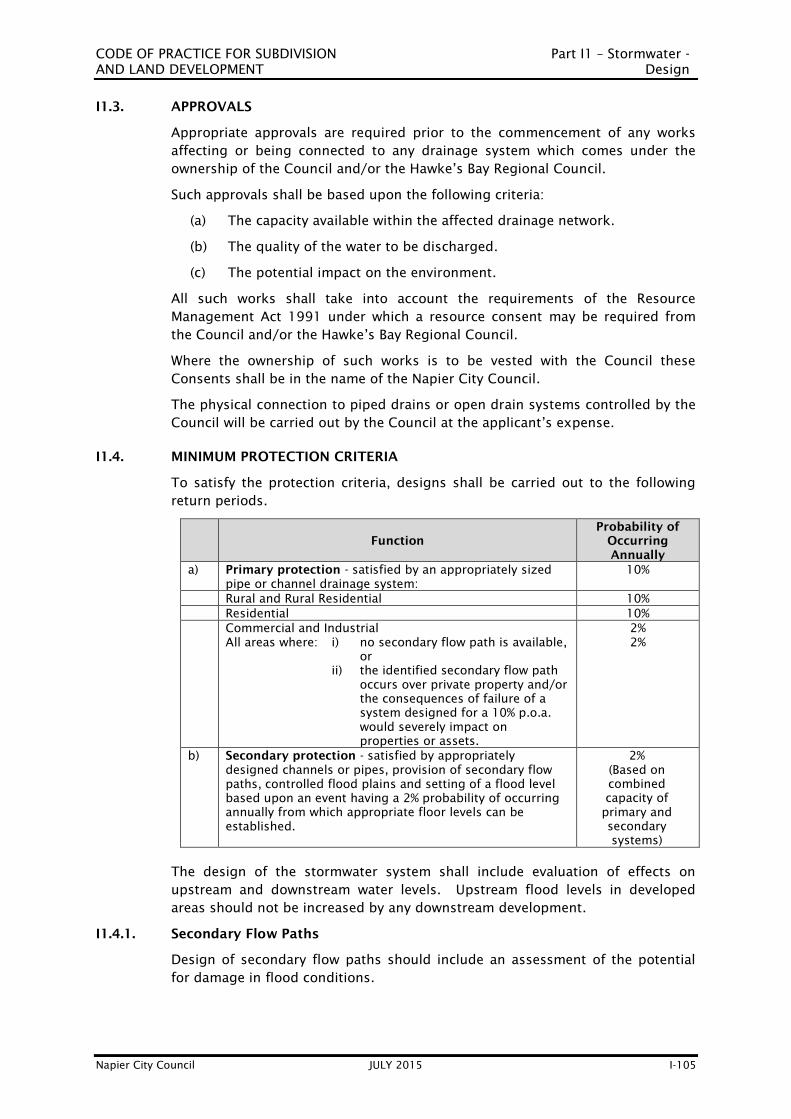
CODE OF PRACTICE FOR SUBDIVISION Part I1 – Stormwater -
AND LAND DEVELOPMENT Design
Napier City Council JULY 2015 I-105
I1.3. APPROVALS
Appropriate approvals are required prior to the commencement of any works
affecting or being connected to any drainage system which comes under the
ownership of the Council and/or the Hawke’s Bay Regional Council.
Such approvals shall be based upon the following criteria:
(a) The capacity available within the affected drainage network.
(b) The quality of the water to be discharged.
(c) The potential impact on the environment.
All such works shall take into account the requirements of the Resource
Management Act 1991 under which a resource consent may be required from
the Council and/or the Hawke’s Bay Regional Council.
Where the ownership of such works is to be vested with the Council these
Consents shall be in the name of the Napier City Council.
The physical connection to piped drains or open drain systems controlled by the
Council will be carried out by the Council at the applicant’s expense.
I1.4. MINIMUM PROTECTION CRITERIA
To satisfy the protection criteria, designs shall be carried out to the following
return periods.
Function
Probability of
Occurring
Annually
a) Primary protection - satisfied by an appropriately sized
pipe or channel drainage system:
10%
Rural and Rural Residential 10%
Residential 10%
Commercial and Industrial
All areas where: i) no secondary flow path is available,
or
ii) the identified secondary flow path
occurs over private property and/or
the consequences of failure of a
system designed for a 10% p.o.a.
would severely impact on
properties or assets.
2%
2%
b) Secondary protection - satisfied by appropriately
designed channels or pipes, provision of secondary flow
paths, controlled flood plains and setting of a flood level
based upon an event having a 2% probability of occurring
annually from which appropriate floor levels can be
established.
2%
(Based on
combined
capacity of
primary and
secondary
systems)
The design of the stormwater system shall include evaluation of effects on
upstream and downstream water levels. Upstream flood levels in developed
areas should not be increased by any downstream development.
I1.4.1. Secondary Flow Paths
Design of secondary flow paths should include an assessment of the potential
for damage in flood conditions.

CODE OF PRACTICE FOR SUBDIVISION Part I1 – Stormwater -
AND LAND DEVELOPMENT Design
Napier City Council JULY 2015 I-106
Secondary flow paths should where possible be provided over public (a)
facilities such as parks, roads, paths, and drainage reserves.
Stormwater runoff from all developed areas and driveways shall be (b)
collected for a 10% POA storm and drained in accordance with the
Building Act so that no nuisance is created.
Any secondary flow path that is recognised as taking excess flow shall (c)
be protected by easement where it is not included in (a) above.
Natural flow channels that are used for the discharge of primary and/or (d)
secondary flows shall be protected by easement to ensure that they are
not built on or disturbed in a manner that might create a nuisance
should water become diverted. (See Part C5.4.4 for easement
requirements).
Buildings shall be located to preserve the secondary flow path and (e)
designed with adequate freeboard.
Where grades are likely to induce erosion, protection measures shall be (f)
incorporated in the design.
Flow paths shall not be restricted by structures such as fences or (g)
hedges.
I1.4.2. Land and Building Sites
The following criteria shall be followed for the development of land and building
sites to ensure that flood risk from a storm having either a 10% or a 2%
probability of occurring annually is minimised.
(a) The flood level shall be established for a storm having a 2% probability
of occurring annually.
(b) All new lots shall be able to be drained to the stormwater outlet
provided. Where the kerb is the outlet the lot shall be at a level that
provides the required drainage and cover to pipes.
(c) Kerb connections have limited capacity. Where flows greater than 8 l/s
are anticipated, (2x 4l/s max. through a double kerb connection), then
a fully-piped system must be designed. (See Section I1.19 “Stormwater
connections”
(d) For all new and reconstructed roads there shall be no surcharge above
sump grates for a storm having a 10% probability of occurring annually.
For roads being reconstructed where this cannot be achieved with
primary protection an alternative design is required.
(e) For all new roads and roads being reconstructed, ponding on roadways
shall be limited to 300 mm above the grate at sumps for a storm having
a 2% Probability of Occurring Annually. For roads being reconstructed
where this cannot be achieved with secondary protection an alternative
design may be required.
I1.5. STORMWATER QUALITY
Where permanent stormwater quality standards are set under Resource
Consents, systems shall be designed to control the discharge of any

CODE OF PRACTICE FOR SUBDIVISION Part I1 – Stormwater -
AND LAND DEVELOPMENT Design
Napier City Council JULY 2015 I-107
contaminants. An acceptable standard for design of such facilities will be
“Design Guideline Manual - Stormwater Treatment Devices, 1992” published by
the Auckland Regional Council.
The Council may require a Developer to construct suitable structures on a
stormwater system to minimise the release of any contaminants in order that the
Council can comply with its discharge consents. (See the rules for stormwater
discharge in the various zones in Volume 1 of the District Plan).
The land use or intended land use will be a consideration in determining the
requirement for any structures together with the requirement of the Regional
Water Resources Plan and the Regional Coastal Plan or any subsequent Regional
Plan.
I1.6. FLOOD ATTENUATION
For large developments or where constraints exist in the downstream
stormwater system a Developer may be required to ensure that the development
creates no increase in downstream storm flow. To satisfy this requirement the
design of stormwater attenuation will be required. This may necessitate the
design and construction of detention ponds. Such ponds shall be designed to
attenuate all flows up to and including a design flow arising from a storm having
a 1% probability of occurring annually. Such ponds shall have spillway
provisions for over-design floods, and the effect of the Probable Maximum Flood
shall be considered.
I1.7. CATCHMENTS
All stormwater systems shall provide for the collection and controlled disposal of
stormwater from within the land being developed together with any runoff from
upstream catchments. In designing downstream facilities the upstream
catchment should be considered as being fully developed to the extent defined
in the current District Plan under both present and deferred zonings together
with such other District Plans where the catchment may encroach outside of the
area of the Council jurisdiction.
Where a developer seeks to develop outside the District Plan Zone then the
design may be required to allow for development of the upstream catchment to
the same standard as the developer seeks.
All stormwater systems and watercourses shall discharge to open drains, except
where Council directs or approves piped drains. Where open drains are retained
through a new development, channel upgrading and/or land raising may be
required.
I1.8. OPEN DRAINS, NATURAL WATERCOURSES AND OVERLAND FLOWS
New open drains or upgraded drains or watercourses should be sized to carry
the full design flow. This may be the primary flow for small drains or the total
(primary and secondary) flow for main watercourses. In some cases, with the
agreement of the Council and where controlled flooding can be accepted under
large storm flows (eg. parks, designated ponding areas) the design can take the
attenuation effects of such areas into consideration.
Two stage channels with a low flow channel and second stage flood channel are
preferred. A typical waterway cross section is provided in Drawing M3.21.

CODE OF PRACTICE FOR SUBDIVISION Part I1 – Stormwater -
AND LAND DEVELOPMENT Design
Napier City Council JULY 2015 I-108
Primary channel and flood berm widths shall be set by the Design Co-ordinator
to suit the design flow and storage requirements. (See Chapter 66 of the District
Plan Part C Section 5.4.4 for minimum requirements.)
Design of open channels and secondary flow paths shall ensure that gradients
will not induce erosion or scour, or where such potential is unavoidable the
design shall incorporate preventive measures, eg silt and debris traps, designed
bank and bed protection.
As required by Part C of Chapter 66 of the District Plan (Code) all open drains
and controlled flow paths shall be protected by easements.
I1.9. STORMWATER RUNOFF CALCULATIONS
Stormwater design usually requires estimation of peak flow, total flow or both
during a storm event. Peak flows are normally suitable for the sizing of pipes
and channels but total flows are required if storage is to be considered.
Flow assessments for stormwater work within the City will need to be modelled
based on rainfall and runoff data.
I1.9.1. Peak Flows
Typically, the Rational Method shall be used for calculating peak surface run-off,
where consideration of storage is not required.
I1.9.2. Runoff Coefficients
For general urban land use minimum run-off coefficients for use with the
Rational Method, are tabled below:-
RETURN PERIOD: ANNUAL EXCEDENCE PROBABILITY
Time of Concentration 1 in 10 year (10%) 1 in 50 year (2%)
30 mins and less 0.55 0.63
1 hour 0.65 0.70
2 hours 0.70 0.74
6 hours and more 0.70 0.75
Note:
(1) Coefficients are based on a 20 mm retention plus a 3 mm/hour
infiltration on non-sealed areas (lawns, gardens, etc
For all other land use types, and including where:-
The impervious surface area does, or will likely exceed 50% of the gross
area, or
The slope of the terrain is, or will, become greater than 5 – 10%,
the coefficient of runoff may be obtained by using Tables 1 & 2 of the New
Zealand Building Code E1/VM
I1.9.3. Hydrograph Estimation Methods
Hydrograph methods provide both peak flows and a model of the flow variations
in a watercourse over a period of time from the beginning to the end of a storm.

CODE OF PRACTICE FOR SUBDIVISION Part I1 – Stormwater -
AND LAND DEVELOPMENT Design
Napier City Council JULY 2015 I-109
Their use enables more comprehensive studies of options for major waterways
than does knowledge of peak flow only in that the effects of ponding and flow
rates over time can be analysed.
A number of accepted industry standard computer based hydrograph techniques
are available in New Zealand. They are best used where stream flow records are
available to enable some degree of calibration, but even without calibration they
can still be used to synthesise a catchment based on input of assumed rainfall
and runoff data.
The use of an accepted hydrograph technique is considered desirable but not
mandatory in studying the effects of changes in land use and flood attenuation
either within channels or storage areas.
Where used the input assumptions shall be clearly identified and peak flows
derived and checked against flows derived from well used empirical methods
appropriate to similar catchment types.
I1.10. RAINFALL INTENSITIES
Rainfall intensities relevant to the Napier City area are shown below, which reflect
the latest predicted effects of climate change.
(Source: NIWA Report AKL-2008-033, April 2008; “Impacts of climate change on
high intensity rainfall in Napier”)
Frequency
(yr)
Duration (hrs) (by 2090)
0.167 0.5 1 2 6 12 24 48 72
2 8 15 19 26 43 60 80 99 108
10 14 24 31 42 71 99 133 168 187
20 17 29 36 49 83 116 157 198 221
30 18 31 40 54 91 127 173 217 242
50 21 35 44 60 100 140 189 239 268
100 24 40 50 68 113 158 213 269 301
I1.11. DESIGN OF PIPED DRAINS AND CULVERTS
All primary systems shall be designed for a storm having a 10% probability of
occurring annually without surcharge above the sump grates. Secondary
systems may allow for surcharge in terms of I1.4.2 (d).
The hydraulic design of piped drains should be based on suitably documented
and currently accepted methods. Examples of pipe design formulae include:
Mannings formula
Colebrook White
The pipe system should be designed to carry the design peak flow.
Concrete or uPVC stormwater pipes may be designed for roughness coefficients
as follows:

CODE OF PRACTICE FOR SUBDIVISION Part I1 – Stormwater -
AND LAND DEVELOPMENT Design
Napier City Council JULY 2015 I-110
Pipe Roughness Table
Pipe Type Colebrook White
(k)
Manning
(n)
Spun concrete
uPVC or HDPE
0.6 mm
0.09 mm
0.012
0.011
Normal acceptable minimum gradients for pipelines shall be as detailed below.
Pipe Internal Diameter (DN) Gradient Percentage Min. Grade
100 mm
150 mm
200 mm
225 mm
250 mm
300 mm
375mm
450mm (and greater)
1.0
0.4
0.3
0.25
0.2
0.167
0.125
0.1
1:100
1:250
1:333
1:400
1:500
1:600
1:800
1:1000
Note: Culverts shall be individually designed.
No pipe in a public drain except for connections shall be less than DN 200. No
connection to a public drain shall be less than DN 100.
No pipe used as a culvert shall be less than DN 300. The minimum size for
culverts under roads shall be DN 375.
Subject to satisfying hydraulic loss requirements pipes joined to smaller
upstream pipes shall be jointed soffit to soffit.
No pipe drain or connection shall connect into or onto a downstream pipe of a
smaller diameter without the written consent of the Council. Where such
consent is given the connection shall be made invert to invert.
Where the inlet to the stormwater system consists of a pipe and headwall in a
watercourse, attention shall be paid to the headwater depth. This shall be done
by evaluating the length of pipe to the first access chamber separately as a short
culvert. In this case, the "tailwater depth" is the depth of water as it enters the
next section of the pipeline, which, if flowing just full, is at the soffit of the pipe.
Pipe systems connecting separate catchment intakes shall be designed taking
into account the relevant times of concentration in each catchment.
The minimum design velocity shall be 0.60 metres per second (m/s) based on a
storm having a 10% probability of occurring annually. This may need
consideration of part flow velocity particularly where pipes have been designed
for a storm having a 2% probability of occurring annually.
Energy losses through bends shall be taken into account. Drawing M3.10 may be
used to assess head loss through access chambers of DN 1050. A drop through
access chambers (over and above the grade line drop) shall be provided to
match the calculated head loss.

CODE OF PRACTICE FOR SUBDIVISION Part I1 – Stormwater -
AND LAND DEVELOPMENT Design
Napier City Council JULY 2015 I-111
Where the velocity of discharge at the outlet of a stormwater pipe is high and
likely to cause erosion, an energy dissipating structure shall be constructed.
Such structures shall be designed to minimise the collection of debris. Where
debris will collect, provision must be made for easy removal.
When designing pipelines discharging to an open outlet, consideration must be
given to the water level of the receiving body at the point of discharge. It is
necessary to establish the water level in the receiving body for the catchment’s
critical time of concentration for the given design storm.
For design purposes, the water level at the point of discharge shall be taken to
be the greater of:-
the modelled water level of the receiving body for the catchments
critical time of concentration for the given design storm, or
the pipe’s soffit level.
Culverts under fills shall be of ample capacity to cope with a design storm
having a 10% probability of occurring annually with no surcharge at the inlet.
They shall be designed to carry the flow from a storm with a 2% probability of
occurring annually under surcharge provided the surcharge will not risk the
stability of the adjacent embankments.
All culverts shall be provided with adequate wingwalls, headwalls, aprons,
detritus traps and/or pits to prevent scouring or blocking. Entry losses shall be
taken into account. At culvert entries the socket end of the pipe shall generally
be laid upstream.
Typical head loss coefficients at culvert entries are:
Entrance Type Coefficient (Ke)
Headwall with socket end of pipe flush 0.2
Headwall with cut pipe flush or projecting from fill square
cut 0.5
Mitred to fill slope 0.7
I1.12. OPEN CHANNELS
Open channels shall be designed based on currently accepted methods such as
the Mannings formula or "industry standard" software packages. All design
assumptions shall be documented and made available to the Council for review.
I1.13. BACKFLOW EFFECTS
Backflow effects shall be designed for, where applicable. Discharges to existing
drains, streams and rivers shall take full recognition of expected flood levels and
shall incorporate backflow prevention as necessary.
I1.14. ACCESS CHAMBERS
Access chambers shall be provided at all changes of direction, gradient and pipe
size, at branching lines, terminations and at a distance apart not exceeding 100
metres. They shall be located such that the access chamber structure is clear of
any boundary by a minimum of 600 mm and the opening is 1.3 metres clear of
the boundary (see also clause I1.16a).

CODE OF PRACTICE FOR SUBDIVISION Part I1 – Stormwater -
AND LAND DEVELOPMENT Design
Napier City Council JULY 2015 I-112
Full size access chambers shall be DN 1050, and constructed as detailed in
Drawings M3.5 to M3.9. If larger chambers are required, they shall be
individually designed, or utilise approved proprietary components, suitable for
the traffic loading characteristics.
Inverts shall be smoothly formed with cement render.
Access chambers on straight sections of pipelines of DN 1200 and larger may be
constructed using offset intakes which may also be used in conjunction with
bends formed using epoxy mortar adhesive.
Shallow type access chambers of DN 600 may be used on lines up to DN 225
and to a maximum depth of 900mm from lid level to invert level provided full
sized access chambers are placed at not more than 100 metre centres, and at
terminations.
Access chambers of over 3 metres depth will not normally be acceptable. When
no alternatives are available they shall be specifically designed.
I1.15. SUMPS
Sumps shall be located in private or public property as necessary to ensure
drainage is provided for the specified rainfall intensities and to ensure that the
total design flow can enter the pipe system. For systems designed to carry low
frequency events (ie. large flows) sump spacings may need to be significantly
closer than the minimum number noted hereafter. The intake capacity of a road
sump with grating and rear entry and acceptable ponding at inlet is 28
litres/sec.
Sump spacings for all roads shall recognise the requirement of the road having
no surcharge above the sump grate in the event of a storm having a 10%
probability of occurring annually.
Sumps and leads in private property or private ways will not generally be taken
over by the Council.
All sumps that will become Council assets shall:
(a) Connect into access chambers, except when connecting into pipes
which are three times the diameter of the connection or larger, with
access chambers within 40 metres, in which cases soffit to soffit
connection using a saddle or prefabricated junction may be acceptable.
(b) Discharge into an open watercourse where no piped stormwater system
is available.
(c) Discharge via sump leads of minimum DN 200 for a single sump and
DN 300 for a double sump. Where the hydraulic gradient of a sump
lead is affected by pipe full conditions in the main drain or drowned
outlets specific design calculations to determine sump lead sizes will be
required.
Road sumps shall also comply with Drawings M2.21 to M2.23 and the following:
(a) Be located at a maximum spacing of 90 metres when collecting surface
runoff from single lanes (4.0 metres wide).
CODE OF PRACTICE FOR SUBDIVISION Part I1 – Stormwater -
AND LAND DEVELOPMENT Design
Napier City Council JULY 2015 I-113
(b) Be located at a maximum spacing of 60 metres where collecting
stormwater over two or more lanes, or on any roads where the adjacent
properties discharge stormwater to the street kerb and channel.
(c) Be provided as double sumps where channel slopes are steeper than 1
in 20 or at the lowest point of sag in a vertical curve where the distance
of catchment exceeds 90 metres.
(d) Be required at all points in a channel where a change in gradient is
liable to result in ponding due to changes in flow, velocity changes, or
on bends where there may be a tendency for water to leave the kerb
and channel.
(e) Be sited at the kerb line tangent points or low points clear of pram
crossings at intersections, to ensure minimal flows occur across the
pram crossing.
(f) With the exception of cul-de-sac heads, sumps shall generally be
located close to section boundaries, where practicable, and clear of
potential accessways or vehicle crossings.
(g) Sumps shall not normally be constructed in rural areas other than in
kerb or concrete channel situations.
Sumps in private property which will not become Council assets shall satisfy the
requirements of the Building Act whilst also satisfying the total stormwater
design needs of the subdivision.
I1.16. LOCATION OF STORMWATER MAINS
Stormwater mains shall generally be laid in the road berm. The Council standard
position for stormwater mains in residential areas is shown on the typical road
cross-section in Drawing M2.18.
The placing of public drains in private properties will only be considered where
particular conditions make the use of the public road not a feasible option.
For any public drainage on private property:
(a) Access chambers should be sited completely on one lot such that the
opening is 1.3 metres clear of the boundary and not on the boundary of
two lots.
(b) Reticulation lines to rear lots should be sited with regard to having a
minimum effect on the building area available on the lot.
(c) Easements shall be provided.
I1.16.1. Clearance to Other Services
The layout of the reticulation system shall provide adequate clearance from
other services.
Acceptable minimum clearances are:
Horizontal a)
Between mains larger than DN 225 and other services 500mm
Between mains DN 225 and less and other services 300mm
Vertical b)

CODE OF PRACTICE FOR SUBDIVISION Part I1 – Stormwater -
AND LAND DEVELOPMENT Design
Napier City Council JULY 2015 I-114
At crossings with other services 50mm – 100mm
(The space shall be filled with compressible material, e.g. pea metal, to prevent
load transference.)
I1.17. STRUCTURAL DESIGN
All pipes shall be designed and founded to resist future loads (weight of fill and
traffic loads) as “pipes under an embankment” as described in Clause 6.3.3 of
AS/NZS 3725 (Design for Installation of Buried Concrete Pipes), using a positive
protection condition and a settlement ratio (rs) of 1.0.
Generally, all pipes and associated structures within road reserve and all other
areas likely to receive traffic shall be designed to HN-HO-72 loading as set out in
the TNZ “Highway Bridge Design Brief”.
I1.17.1. Minimum Cover and Maximum Cover
Maximum and minimum covers shall be as specified hereunder. Any design
involving a cover outside this range will only be approved if a complying option
is shown to be impractical and then the alternative must be supported with full
calculations.
Maximum depth to invert 3.0 metres
Minimum cover in roads 750 mm
Minimum cover in berms and paths 600 mm
Pipelines shall not be laid within 2 metres of any structure unless no other
option is available and the Design Co-ordinator can provide calculations and a
construction system that will ensure that neither the structure nor pipeline will
suffer any short or long term distress and that the pipe can be reasonably
accessed for future maintenance.
I1.17.2. Trench Slope
Where the slope of a trench is 1:15 or greater, anti-scour blocks (also known as
water-stops) shall be provided, to prevent surface water running along the
pipeline and scouring the surround.
They shall be constructed as per Drawing M3.4 using 20 MPa concrete, keyed
into the sides and invert of the trench by at least 150mm, and extend 300mm
above the top of the pipe.
They should be positioned behind every secon pipe joint, or as otherwise
directed by the Asset Manager.
I1.18. STORMWATER PUMPING
Stormwater pumping will only be considered for approval where gravity disposal
is not a feasible solution.
Design philosophy, technical details and provision of emergency power should
be discussed with the Council before commencement of detailed design.
Pumping systems shall be specifically designed generally using a multi pump
system to best balance the need for regular pump operation against the relative
infrequency of major storm events. All electrical equipment shall be capable of
servicing up to 15 starts per hour.

CODE OF PRACTICE FOR SUBDIVISION Part I1 – Stormwater -
AND LAND DEVELOPMENT Design
Napier City Council JULY 2015 I-115
All pumps in a station shall be of the same size with an additional installed
pump as standby. Depending on the economic consequences of flooding during
a pump station power "outage" council may require that on site emergency
power generation be provided. All stormwater pump stations should have
facilities to enable generator power connection, under emergency conditions.
Valving of pumps shall be such that maintenance can be undertaken on the
standby pump and reflux without interfering with the operation of the duty
pump. Pipes of DN 100 or larger shall be ABS, API Schedule 40 line pipe,
concrete lined steel or cast iron with all bends and valves adequately protected
against movement. Flanged or welded fitting shall be provided throughout with
a pair of gibault joints or similar in the system to facilitate dismantling.
Stormwater pump stations shall incorporate control, monitoring, alarm and
telemetry communication systems to Council standards at the time of the
design. All equipment shall comply with "NCC Utilities, Standard Electrical
Details".
I1.19. STORMWATER CONNECTIONS
Urban lots shall be provided with stormwater connections at such depth at the
boundary that a drain is able to be extended from the connection at grades and
cover complying with the Building Act, to the furthest point on the lot.
Unless approved otherwise within new developments, all stormwater connections
shall be made direct to a stormwater main, with the object of avoiding the need
for a bubble up sump within the lot. An inspection or rodding eye will be
required within the boundary.
In areas where lots slope up from the road a connection into the kerb face may
be approved. It shall utilise a 100 x 75 x 3 galvanised steel RHS taken through
the kerb (Drawing M3.15). The connection from the kerb to the boundary shall
be RHS with a DN100 uPVC adaptor fitted.
Connections shall extend 500 mm into the lot and shall be located near the
centre of the lot unless the road is on a significant slope in which case the
connection shall be placed 1.0 metre from the low side boundary. All
connections where practicable shall have at least 300 mm horizontal clearance
to adjacent services.
In areas where lots do not conform with Section E1.12 (where mountable kerbs
are used) or in cul-de-sac heads where connection to kerb may not be practicable
through vehicle access provisions, connections shall be provided direct to the
stormwater main or an adjacent access chamber.
For all residential lots DN150 connections will be required as a minimum, unless
agreed otherwise. For residential sites in excess of 600 square metres, pipes
shall be sized DN150 or above, to suit expected discharges.
For industrial/commercial lots connections shall be based on the lot size and the
minimum requirements for stormwater provisions as defined by the Building Act.
A wet chamber shall be installed inside the boundary for all
industrial/commercial lots. The chamber shall be a minimum of DN600 and be
fitted with a suitable solid lid and shall not be used as a sump.

CODE OF PRACTICE FOR SUBDIVISION Part I1 – Stormwater -
AND LAND DEVELOPMENT Design
Napier City Council JULY 2015 I-116
Shallow type access chambers (DN600) shall have a maximum depth of 900 mm.
Where the depth exceeds 900 mm the diameter shall be DN1050.
Where connections to stormwater mains are required they shall be made as
follows:
(a) When the connection is DN300 or larger it shall be connected at an
access chamber.
(b) Where the connection diameter exceeds one third of the main drain
diameter the connection shall be via an access chamber unless the
connection is made using a factory-made “Y” fitting, or a saddle
reinforced with glass fibre.
(c) Connections to mains of up to DN300 shall utilise factory made Y
fittings.
(d) All piped connections to stormwater mains shall be no less than 150
mm diameter.
(e) Connections to larger mains shall utilise properly manufactured
saddles.
(f) Connections to mains of DN1200 or larger may be made by breaking a
hole in the main and placing the connection, trimming it neatly to the
shape of the inside of the main and neatly epoxy mortaring the two
together.
(g) Where a connection of DN150 or smaller needs to go deeper than 1.8
metres below ground level for a soffit to soffit joint a ramped riser shall
be constructed to bring the connection to within 1.2 metres of ground
level provided the site can be adequately serviced. A typical example is
illustrated in Drawing M3.13.
(h) Connections shall not be made directly to stormwater mains which are
more than 3.0 metres deep to the invert of the pipe. Such situations
shall be overcome by the construction of a shallower branch drain laid
from an access chamber on the deep drain and connections made from
the shallower drain.
I1.20. SUBSOIL DRAINS
Subsoil drains shall be installed as required to lower ground water levels and
pressures, and avoid any potential for future build-up of ground water levels and
pressures. They shall be specifically designed to cope with estimated flows and
superimposed loads.
I1.21. MATERIALS
I1.21.1. Pipe Materials
Whilst the following pipe materials can provide acceptable solutions for certain
uses not all materials will be accepted for general use. The Design Co-ordinator
should discuss preferred pipe types with the Council prior to completion of
design drawings and specification. Pipes shall comply with the industry
accepted standard applicable at the time. Pipe selection shall recognise the soil
material and groundwater around the pipe.

CODE OF PRACTICE FOR SUBDIVISION Part I1 – Stormwater -
AND LAND DEVELOPMENT Design
Napier City Council JULY 2015 I-117
Pipes used shall be new and of good quality. All pipes shall utilise flexible joints
of a type recommended by the manufacturer and as approved by the Council for
the use being proposed.
Material Preference Material Standard Laying Standard
UPVC –
Unplasticised PVC
Approved
provided adequate
cover and strength
SN8 - AS/NZS
1254
Design AS/NZS
2566:1
Laying AS/NZS
2566.2
MPVC – modified
PVC
OPVC – orientated
PVC
HDPE Approved
AS/NZS 4130
NZS 7601
NZS 7602
ABS
Approved,
particularly for
above ground use
and shallow cover
AS/NZS AS 3518
BOSSPIPE -
Polypropylene Approved AS/NZS 5065
DICL – Ductile Iron
Cement Mortar
Lined
Approved for
shallow cover
AS/NZS 2280 or
BS EN 598
FRP- Fibreglass
Reinforced Plastic Approved
Reinforced
Concrete Preferred material
AS/NZS 4058 –
CLASS 2 (X)
Minimum
AS/NZS 3725
CLS –Cement Lined
Steel
Approved,
particularly for
large diameter
pumping mains
NZS 4442
CI – Cast Iron
By preference
superseded by
DICL
Corrugated Steel Not approved for
any use AS/NZS 2041.4 AS/NZS 4406
Galvanised Steel Shallow berm
connections only
Earthenware
To check currency of standard, refer to Appendix M7.
See section I1.21.1.1 to I1.21.1.6 below for additional details.
I1.21.1.1. Concrete Pipes
Concrete pipes shall be reinforced concrete rubber ring jointed and shall comply
with AS/NZS 4058 “Precast concrete pipes (pressure and non-pressure)". They
must be marked with the date of manufacture, and cured for at least ten days
before delivery. Pipes without a date mark will not be accepted.
Flush jointed pipes above DN900 are acceptable for stormwater provided they
are used with approved external jointing sleeves.
The minimum strength class of pipe shall be Class 2(X).
I1.21.1.2. Cement Lined Steel Pipes

CODE OF PRACTICE FOR SUBDIVISION Part I1 – Stormwater -
AND LAND DEVELOPMENT Design
Napier City Council JULY 2015 I-118
Steel pipes shall meet the requirements of NZS 4442: - "Welded steel pipes and
fittings for water, sewage and medium pressure gas". Unless otherwise
approved, steel pipes shall be lined internally with mortar. When used in above
or below ground situations, special external protective coatings approved by
Council shall be used.
These may include tape wrapping, hot galvanising or paint/epoxy coating
systems. Jointing systems shall be as recommended by the manufacturer and as
approved by the Council.
I1.21.1.3. Unplasticised PVC Pipes (uPVC)
Pipe stiffness for stormwater drains shall be SN16 for sizes less than 300mm
diameter, and SN8 for all other sizes.
Class SN8 uPVC pipes for stormwater shall comply with AS/NZS 1254 “PVC pipes
and fittings for stormwater and surface water applications”.
Class SN16 uPVC pipes shall comply with AS/NZS 1260 “PVC-U pipes for drain,
waste, and vent application”.
When SN16 pipe is unavailable, this may be substituted with PN9 pipe,
conforming to AS/NZS 1447.
Rubber ring joining system shall be used.
Gibault joints shall be used at junctions with cast iron and concrete lined steel
fittings except where cast iron fittings with formed rubber ring sockets are used.
I1.21.1.4. High Density Polyethylene (HDPE)
HDPE pipes shall comply with NZS 7601 - Specification for polyethylene pipe
(Type 3), and NZS 7602 - Specification for polyethylene pipe (Type 5) for cold
water services (stormwater and wastewater pressure main use) and AS/NZS 4130
polyethylene (PE) pipes for pressure applications.
Joints shall be electro-fusion welded, flanged or approved mechanical couplings.
Only jointing systems that provide a clean unimpeded bore will be approved.
I1.21.1.5. ABS Pipes
ABS pipes are preferred for wastewater pump stations and valve chambers. ABS
pipe and fittings of appropriate pressure ratings shall comply with AS 3518.
I1.21.1.6. Galvanised Steel Pipe
Galvanised steel pipes are required for shallow stormwater laterals under berms
and footpaths to kerb. Pipes shall be medium wall hot dipped galvanised.
Connections from the boundary to the kerb shall preferably be RHS 100 x 75 x 3
galvanised.
Jointing systems shall be as recommended by the manufacturer and as approved
by the Council.
I1.21.2. Pipe Strength and Bedding
The pipe strength and bedding type shall be selected to meet the requirement of
the design loading condition. This may be derived from NZS/AS 3725 (Design
for installation of buried concrete pipes) or NZS/AS 2566.1 (Flexible buried
pipelines: structural design) or from the manufacturer's published tables.

CODE OF PRACTICE FOR SUBDIVISION Part I1 – Stormwater -
AND LAND DEVELOPMENT Design
Napier City Council JULY 2015 I-119
Granular bedding shall be used with all pipes except in extreme load situations
when structural design shows it to be inadequate. Bedding shall extend from
100 mm below the pipe, around it and to a height of 100 mm above the pipe
(see Drawings M3.2 and M3.3). Bedding material shall be clean pea metal or
other granular material approved by the Council.
Concrete haunching or surround shall be used with rigid walled pipes subject to
high loads in firm natural ground. Concrete haunching shall rise beyond halfway
up the pipe. Concrete surround shall extend in one pour from the natural
ground not less than 100mm below the pipe underside, around the pipe by a
minimum of 100mm at any point and to a height not less than 100mm above
the pipe crown. Both concrete haunching and concrete surrounds shall be
cleanly broken in the vertical plane at every pipe joint and left with a gap at least
25mm wide to facilitate seismic movement of pipe joints. The seismic gap shall
be filled with neatly cut compressible material such as expanded polystyrene.
Pipes to be laid in soft flexible soils shall be specifically designed to take into
account the conditions.
I1.21.3. Precast Access Chambers
Precast concrete access chambers shall comply with the requirements of AS/NZS
4058 and have an internal diameter of 1050mm. The reinforced concrete top
shall have a minimum thickness of 150mm and be capable of withstanding HN-
HO-72 traffic loadings.
I1.21.3.1. Shallow Access Chambers
Shallow access chambers shall utilise DN600 sump barrels with a standard
Council cast iron frame and cover. Maximum invert to lid depth is limited to
900mm.
I1.21.3.2. Step Irons
Access chambers other than shallow access chambers shall be provided with
“approved” plastic coated step irons. Step irons shall be of the “dropper” or
“safety” type such that a foot will not slide off and shall be spaced as shown in
Drawing M3.5. Step iron holes in the riser shall be epoxied after placing of the
step iron to ensure the access chamber is watertight.
I1.21.3.3. Access Chamber Covers and Frames
Access chamber covers shall be of the hinged, circular variety, nominally 600mm
diameter, and manufactured from first quality heavy duty cast iron, and coated
with bituminous protective coating.
The covers shall be set a maximum of 400mm above the underside of the PC
chamber slab, and bedded on concrete spacers.
Proprietary bolt-down chamber covers, from an approved supplier, may be used
where appropriate. They shall be set to level, and secured to the concrete slab,
using suitable fixings, or cast-in anchors. When used in roads, the hinge shall
be located on the side nearest to oncoming traffic.
I1.21.3.4. Inverts and Benching
All pipes through access chambers shall have their inverts neatly lined with
cement render to NZS 3114 concrete surface finish (U3).

CODE OF PRACTICE FOR SUBDIVISION Part I1 – Stormwater -
AND LAND DEVELOPMENT Design
Napier City Council JULY 2015 I-120
All inverts shall be carried vertically to the soffit of the pipe before haunching
back to the access chamber walls. See Drawings M3.5 and M3.8.
I1.21.4. Concrete and Mortar Materials
The following NZ Standards shall be used as a means of compliance with this
specification.
NZS 3104 Specification for Concrete Production
NZS 3109 Concrete Construction
NZS 3124 Concrete for Small Works
NZS 3114 Concrete Surface Finish
Concrete for all uses shall be Grade 20 high grade concrete with a minimum
crushing strength at 28 days of not less than 20 MPa.
Mortar and its components shall comply with NZS 3103.
I1.22. RURAL STORMWATER - PARTICULAR REQUIREMENTS
Stormwater and flood mitigation standards for rural developments shall be as
covered in the preceding parts of this Code except as extended or modified
below.
All new house sites shall either:
a) Identify a building site that will not be subject to inundation from a
storm having a 2% probability of occurring annually.
or
b) Show on the title a level to which habitable floors must be built to be
free of flooding from a storm having a 2% probability of occurring
annually.
However in no case shall a building site be selected where ponding on
surrounding land from a storm having a 2% probability of occurring annually
exceeds 500mm.
Roads and other components of land development work shall be protected by
stormwater drainage systems designed to the standards defined in the
preceding parts of this Code except that systems may utilise open drains or
combination of pipes and open drains where appropriate.
Irrespective of previous details it is intended that all roads within the primary
road classification shall be designed with stormwater systems capable of
ensuring that the running lane of the road is kept free of inundation during a
storm having a 10% probability of occurring annually.
House stormwater connections need not be constructed as part of the land
development works where it can be demonstrated that the house site can be
drained to ditches or natural drainage paths without risk to land stability. This
must be demonstrated even if it is likely that roof water will be collected for
water supply.

CODE OF PRACTICE FOR SUBDIVISION Part I1 – Stormwater -
AND LAND DEVELOPMENT Design
Napier City Council JULY 2015 I-121
I1.23. WASHDOWN FACILITIES
Washdown facilities are to be designed to prevent any contaminated washdown
water from entering the stormwater system and at the same time prevent the
infiltration of storm water into the wastewater system. The solution that is used
will depend on the size of the installation and the types of contamination that
may impact on both the stormwater and wastewater networks.
Options that are considered suitable for washdown facilities are detailed as
follows:-
I1.23.1. Roofing
Roofing the installation has the advantage that the stormwater and
wastewater systems are separated and there isn’t a need for complicated
control systems to ensure that cross connections don’t occur between
the stormwater and wastewater networks.
With roofing, stormwater is collected on the roof and piped directly to
the stormwater network. Stormwater cannot enter the wastewater
system provided the washdown pad is higher than any surrounding
ground. Surrounding ground that collects stormwater should be graded
away from the washdown pad and the stormwater collected and drained
to the stormwater network.
Washdown water is directed to a dedicated wastewater connection to the
wash via any grit and grease traps that may be required to protect the
wastewater network from oil, grease and solid material that could
damage the wastewater network.
The design of grit and grease traps are to be to the Works Asset
Managers approval. The design will depend on the function and size of
the washdown facility. In the bigger installations the traps will take the
form of an approved interceptor such as a 3 chamber API tank or 3 stage
access chamber system.
The design of interceptors and traps should be such that they can be
easily maintained at regular intervals and in the event that they become
overloaded they should “fail safe”.
I1.23.2. Automated Valving
This option provides and automated system of valves that control how and when
washdown water is directed to the wastewater network and stormwater to the
stormwater network.
Only approved proprietary systems can be used.
All installations are to be fitted with oil, grit and grease traps as appropriate to
the installation. Traps are to the Works Asset Manager’s approval.
I1.23.3. Acceptable Solution
Drawings M3.24 and M3.25 of the Code show a schematic layout for a small to
medium sized washdown facility using a pumped output to the wastewater
network.
Installations using this solution must be submitted for approval and approval is
to the Works Asset Manager’s discretion.

CODE OF PRACTICE FOR SUBDIVISION Part I1 – Stormwater -
AND LAND DEVELOPMENT Design
Napier City Council JULY 2015 I-122
Key points to note in this design are as follows:-
The pumped outlet to the wastewater networks must exit at a higher
level than the outlet to the stormwater network.
The inlet to the stormwater discharge pipe must be a minimum of 100
mm below the connection pipe between the chambers.
The pump and the water supply to the washdown facility are controlled
by a push button timer. The timer has to be active before the pump and
the water supply to the washdown facility are available for use. Note: If
the system is in stormwater mode when the timer is activated, the water
supply will remain locked out until the pump lowers the water level below
stormwater mode.
The pump is controlled by float switches and an additional float is
required to lock out the pump and the washdown facility when the
system is working in stormwater mode.
The water supply to the washdown facility is to be isolated by the float
that determines when the facility is in stormwater mode. This will occur
whenever the water level rises above the setpoint of the stormwater
mode float switch. Note, if the pump fails for any reason water levels will
rise to the point where the system will change to stormwater mode and a
locked out water supply could be an indication of a pump failure.
CODE OF PRACTICE FOR SUBDIVISION Part I2 – Stormwater -
AND LAND DEVELOPMENT Construction
Napier City Council JULY 2015 I-123
I2. STORMWATER – CONSTRUCTION
I2.1. GENERAL
All drainage systems shall be constructed to lines and grades specified in the
design drawings and to standards suitable for ensuring pipelines are able to
serve their purpose over the required design life. Drainage construction
methods shall comply with the appropriate technical standards and codes.
I2.2. SETTING OUT
All drainage works shall be set out to the position and levels detailed on the
approved drawings.
Where the alignment is related to the road boundary, drains shall be laid with
reference to permanent land transfer boundary pegs or temporary boundary
marks placed by the registered surveyor responsible for the final land transfer
pegging. Pipes shall be laid by reference to the kerb line only where the
surveyor has confirmed that the kerb is located in the correct position.
All pipes must be laid to the gradients specified on the drawings. Final
acceptance will be by visual or CCTV inspection, to ensure alignment meets
appropriate tolerances for pipe diameter and gradient, up to a maximum of ±
10%. Low spots that hold water will not be permitted.
I2.3. TRENCHING
Trenches shall be opened only after all required Consents and Trench Opening
Notices have been uplifted. All trenching shall comply with the safety
requirements of the Health & Safety in Employment Act.
All trenches shall be opened up to widths and depths suitable for enabling the
requisite bedding metal thickness below the pipe to be placed (not less than
100mm). The trench width shall be kept to those dimensions detailed in the
design drawings which ensure that it is narrow enough to allow the pipe to be
laid in trench conditions but wide enough to enable pipe surround material to be
adequately placed and compacted.
All trenching in Napier roads or on services to be taken over by Council shall be
carried out in accordance with "Specification for Service Maintenance Operations
and New Service Installations within Road Reserve (Including Trench Excavation
and Reinstatement)".
I2.3.1. Trenches in Open Land
Trenches may be opened up for up to 200 metres ahead of pipelaying provided
trench depth and material are of adequate stability to minimise any risk of
trench failure and to ensure safety of workers and the public.
I2.3.2. Trenches in Road
Trenches in stable ground may be opened to a maximum of 50 metres in
advance of pipe laying, but this distance shall be reduced where the public or
network utility services are endangered or where traffic routes are restricted.

CODE OF PRACTICE FOR SUBDIVISION Part I2 – Stormwater -
AND LAND DEVELOPMENT Construction
Napier City Council JULY 2015 I-124
I2.4. CONTROL OF WATER
The Contractor shall keep the excavations free from water and wastewater at all
times and shall provide all such pumping plant, pipes, and materials as may be
required for this purpose.
Under no circumstances shall any water be allowed to drain directly into the
existing wastewater drains.
I2.5. PIPE CONDITION
All pipes supplied for use in the works shall be new and in good condition. They
shall be examined before being laid and any pipe showing defects of any
description shall be removed from the site and not used in Council works. Any
pipes damaged during laying shall likewise be removed except where damage is
minor or to repairable coatings. In such cases the coatings and other damage
shall be repaired to the manufacturer’s specification so as to achieve a condition
at least as good as a new undamaged pipe.
Handling of pipes and fittings shall be in accordance with the manufacturer's
recommendations. All reasonable care shall be taken in handling pipe materials
to preserve intact the pipe coatings, linings, structural strength and the various
features necessary for long service. Pipes with external coatings shall be lifted
using wide slings; ropes and chains shall not be used.
I2.6. PIPE LAYING AND JOINTING
A registered drainlayer shall be employed to supervise and certify all pipe laying
works.
The laying and jointing of pipes shall be strictly in accordance with the
manufacturer's recommendations, and Council's requirements. Bedding shall be
as detailed in the design documents.
Where a pipeline is to be constructed through soft ground, unsuitable
foundation material shall be removed and replaced with sound material.
Alternatively, other approved methods of construction shall be carried out to
provide an adequate foundation for the pipeline.
Drainage structures including access chambers shall be clear of boundaries and
other obstructions.
Pipelines shall be laid clear of existing buildings. Pipelines shall not be laid in
front, side and rear yards unless clearance needs have been previously
determined by the Design Co-ordinator having regard to possible disturbance of
structures.
I2.7. JOINTING PIPES
Jointing shall be strictly in accordance with the manufacturer's instructions or in
accord with specific design details.
Spigots, sockets, rubber rings and sleeves etc shall be thoroughly cleaned and
lubricated where appropriate before jointing.

CODE OF PRACTICE FOR SUBDIVISION Part I2 – Stormwater -
AND LAND DEVELOPMENT Construction
Napier City Council JULY 2015 I-125
I2.8. PIPE CONTAMINATION
Adequate precautions shall be taken while laying pipes to prevent the entry of
debris. Where required, the pipeline shall be temporarily sealed with fixed
covers or bungs to prevent entry of foreign matter or groundwater.
I2.9. CONNECTIONS
Connections shall be in accordance with Section I1.19.
Each connection shall be laid soffit to soffit except when a drop is constructed.
Each connection end shall be marked by a stake (plastic flexipost or similar)
extending to 600mm above ground level.
Connections whether to reticulation lines or to access chambers shall be sealed
by a factory made sealing cap.
I2.10. ACCESS CHAMBER CONSTRUCTION
Access chambers shall be constructed as detailed in Drawings M3.5 to M3.9.
Where more than a single riser is used in an access chamber, riser joints shall be
sealed with epoxy mortar.
Shallow access chambers of 900mm or less to invert, may be formed using
DN600 reinforced concrete pipe, with construction otherwise being to the
requirements of this Code.
Where an access chamber excavation is found to be in soft ground the area
under the access chamber shall be undercut down to solid and backfilled with
hard fill to provide an adequate foundation for the access chamber base.
Alternatively work can be stopped and a specific solution designed.
Before any concrete is placed the base of the trench shall be free of all debris
and water.
Stormwater access chambers inverts shall be smoothly formed with cement
render.
Pipes shall be laid 'soffit to soffit' taking into account grade of the pipelines and
any designed drop through the access chamber.
When uPVC pipes are used factory made "access chamber shorts" shall be used
at access chamber entry points.
Care shall be taken to ensure that chamber access holes are orientated correctly.
The walls, benching and invert of access chambers shall have smooth internal
finish. Any leaks shall be neatly plugged.
Precast concrete access chamber covers shall be placed, jointed and sealed with
mortar onto the top riser. Cast iron access chamber frames shall be bedded on
epoxy mortar.
Access chamber frames shall be set proud of the surrounding ground levels by
10mm and set at the same crossfall and gradient as the surrounding surface.
The immediate surrounding surface shall be shaped up to the edge of the
chamber frame over a distance of not less than 500mm all round.

CODE OF PRACTICE FOR SUBDIVISION Part I2 – Stormwater -
AND LAND DEVELOPMENT Construction
Napier City Council JULY 2015 I-126
I2.11. INLET AND OUTLET STRUCTURES
Wing-wall inlet and outlet structures shall typically be of the precast type
complying with NZS 3109 “Specification for concrete construction”, with surface
finishes in accordance with NZS 3114 “Specification for concrete surface
finishes”.
Non-precast types will require specific design approval.
All structures shall be constructed on adequate foundation material.
For outlet structures, specific design of scour prevention and energy dissipation
will be required, including the consideration of baffles and rock rip-rap. Fencing
around the structure may be required where human access to the inlet/outlet
structure is likely and/or the height of the structure is greater than 1.2m.
All steel used on inlet gratings shall be hot dip galvanised.
I2.12. COUNCIL INSPECTIONS
Council Officers shall be given not less than one working days’ notice to allow
them to carry out all inspections required by Chapter 66 of the District Plan Part
A, Appendix A2.
I2.13. TRENCH BACKFILLING AND SURFACE REINSTATEMENT
Backfilling, around and for a depth of 100 mm over the pipes shall be with
bedding material. This material shall be carefully placed and well tamped with
hand rammers around and above the pipes with particular attention to
compacting under the pipe haunches.
The remainder of the backfilling and surface reinstatement shall be in
accordance with Council's "Specification for Service Maintenance Operations and
New Service Installations within Road Reserve (including Trench Excavation and
Reinstatement)".
Backfilling shall be carried out immediately after the pipes have been inspected
and the “as built” information recorded. The Contractor may wish to carry out a
test at this stage. In some circumstances backfilling may be required
immediately after laying.
I2.14. TESTING OF ACCESS CHAMBERS
New access chambers shall be tested for water tightness by filling with water.
After all absorption has taken place the water level shall be maintained for 30
minutes and a visual inspection carried out. Any leakage detected shall be
made good and the access chamber retested until no leakage occurs.
I2.15. TESTING OF STORMWATER MAINS
All stormwater mains of DN450 or smaller shall be tested in accordance with the
water test described on drawing M3.23. Leaks shall be remedied as required for
wastewater mains.
Video inspections will only be required where faults have been identified or
where the inspections, as required in terms of Chapter 66 of the District Plan
Part A, Appendix A2, have not been notified to Council.

CODE OF PRACTICE FOR SUBDIVISION Part I2 – Stormwater -
AND LAND DEVELOPMENT Construction
Napier City Council JULY 2015 I-127
I2.16. AS BUILTS AND COMPLETION DOCUMENTATION
On completion of construction, information and documents as required by
Chapter 66 of the District Plan Part A and as detailed in Appendix M1, (As-built
Information) shall be provided by the Construction Co-ordinator.

CODE OF PRACTICE FOR SUBDIVISION Part I2 – Stormwater -
AND LAND DEVELOPMENT Construction
Napier City Council JULY 2015 I-128

CODE OF PRACTICE FOR SUBDIVISION Part J1 – Design for
AND LAND DEVELOPMENT Residential Subdivisions
Napier City Council JULY 2015 J-129
J. RESIDENTIAL SUBDIVISIONS
J1. DESIGN FOR RESIDENTIAL SUBDIVISIONS OF UP TO THREE LOTS
This section only applies to the design for Residential subdivisions or multi-unit
residential developments of up to 3 Lots or Units serviced by non-public
accessways, involving no new public roads or services.
For subdivisions greater than 3 lots, refer to the mandatory requirements in
Sections A, B & C of this Code, and Parts D – I for a means of compliance.
J1.1. GENERAL
For small residential subdivisions or multi-unit residential developments of up to
3 lots or units with no requirement for bulk earthworks or construction of new
public roads or network utility services, the Developer may carry out a basic
design without the use of a professionally qualified Design Co-ordinator subject
to satisfying the following conditions:
(a) The project shall first be discussed with the Council, who will, based on
their knowledge of the site, decide whether the expeditious design
approach is appropriate.
(b) If considered to be appropriate, the requirements of this section shall
be considered an acceptable solution provided they are complied with
in full. Variations to these expedited requirements may only be
addressed by the Developer engaging a Design Co-ordinator to address
the project in terms of the full requirements of this Code.
(c) The person providing the subdivisional design drawings whilst not
being required to be a fully professionally qualified person shall be able
to show some experience in the area of small subdivisional
development.
J1.2. EARTHWORKS
Earthworks for such projects within the limits in Chapter 66 of the District Plan
Part C shall be limited to excavation for road formation and network utility
services. Excavated material shall be removed from the site or used to backfill
trenches. No earthworks for building sites may be carried out under this part of
the Code.
J1.3. PRIVATE WAYS, FORMED ACCESS LOTS, DRIVEWAYS
Vehicular access able to be provided under this part of the Code is limited to
private ways, formed access lots and driveways either shared or private.
Vehicle accessways shall be designed and constructed according to Part F1.12 of
this Code.
J1.4. LOCATION OF SERVICES
All services provided from the road to rear lots, shall be located within the
accessway.
All services requiring to be extended shall be installed at the time of subdivision.
CODE OF PRACTICE FOR SUBDIVISION Part J1 – Design for
AND LAND DEVELOPMENT Residential Subdivisions
Napier City Council JULY 2015 J-130
All services shall be separated by at least 300mm horizontally.
Minimum cover for pipes shall be 600mm
Easements for water, stormwater and wastewater shall be provided where
privately owned utilities cross other land in terms of Chapter 66 of the District
Plan, Part C5.4.3. (See drawing M3.22 for details).
J1.5. UTILITY SERVICES – URBAN
J1.5.1. Stormwater (See also I1.19)
Urban lots shall be provided with stormwater connections at such depth at the
boundary that a drain is able to be extended from the connection, at grades and
cover complying with the Building Act, to the furthest point on the lot.
In areas where lots slope up from the road the connection may be into the kerb
face. It shall utilise a 100 x 75 x 3 galvanised steel RHS taken through the kerb.
Connections shall extend 500mm into the lot and shall be located near the
centre of the lot unless the road is on a significant slope in which case the
connection shall be placed 1 metre from the low side boundary.
In areas where lots do not conform to E1.12. where mountable kerbs are used or
in specific cul-de-sac heads, connections shall be provided direct to the
stormwater main. They shall be a minimum of DN150 for sites up to 600 square
metres. Sites in excess of 600 square metres shall be sized to match potential
discharges.
J1.5.2. Wastewater (See also H1.9)
All lots/units shall be provided with wastewater connections at such a depth at
the boundary that a drain is able to be extended from the connection at grades
and cover complying with the Building Act, to the furthest likely wastewater
connection point on the lot subject to the Council being able to provide a service
at the specific depth.
Subject to satisfying this criterion the end of the connection which shall be
located 500mm into the lot shall be at a depth to invert of between 700mm and
1600mm.
Where a connection of DN150 or smaller needs to go deeper than 1.8 metres
below ground level for a soffit to soffit joint a ramped riser shall be constructed
to bring the connection to within 1.2 metres of ground level provided the site
can be adequately serviced. A typical example is illustrated in Drawing M3.13.
Connections shall not be made directly to trunk mains, or drains more than 3
metres deep to the invert of the pipe. Such situations shall be overcome by the
construction of a shallower branch drain laid from an access chamber on the
deep drain and connections made from the shallower drain.
Residential connections shall be DN 100 and shall be located centrally on the lot
except where lots have a significant fall from one side to the other in which case
the connection shall be approximately 2.4 metres from the low side of the lot.
Connections may be made, as detailed in Drawing M3.11.

CODE OF PRACTICE FOR SUBDIVISION Part J1 – Design for
AND LAND DEVELOPMENT Residential Subdivisions
Napier City Council JULY 2015 J-131
J1.5.3. Water Supply
Each lot/unit shall be serviced with a DN15 connection with a meter manifold
located 300mm outside the property from the road boundary frontage.
Where the head available at any point on the lot is less than 20 metres, then
specific design will be required.
Dwelling sites shall be within the maximum distance of a fire hydrant as set out
in the fire services "Code of Practice for Fire Fighting Water Supplies".
J1.5.4. Other Utility Services
Telecom and Power services shall be provided to the lot boundary.
J1.6. UTILITY SERVICES – RURAL
Where Council services are available, standards shall be as for urban.
Where Council services are not available the Developer shall confirm that
suitable provision is available for services as follows:
J1.6.1. Wastewater Disposal
Systems shall be investigated and designed in terms of H1.15. of this Code "On
Lot Treatment and Disposal of Household Wastes".
J1.6.2. Stormwater Disposal
A discharge location clear of the preferred building site, safe from causing or
being affected by potential erosion, and unlikely to cause surface ponding
nuisance shall be identified. This may be a gully, drainage ditch, a natural
drainage path or a soak pit.
J1.6.3. Water Supply
A suitable water supply method shall be identified in terms of the requirements
detailed in section G1.20.
J1.6.4. Other Utility Services
Telecom and Power services shall be provided to the lot boundary.
J1.7. SOLID WASTE MANAGEMENT
All residential developments must provide adequate facilities for the storage and
collection of domestic refuse, and recyclable materials.
Developers must include proposals for managing domestic waste, as part of
their consent application.
Options may vary from normal domestic provisions for individual households, to
suitable communal facilities for multi-unit complexes served by private access.
Each development will be assessed on its merits in order to achieve the best
practical and economic solution.
J1.8. OTHER FACILITIES
J1.8.1. Mail Boxes
Mail boxes must be provided at the front section boundary with the road
reserve.

CODE OF PRACTICE FOR SUBDIVISION Part J2 – Design for Multi-Storey Buildings /
AND LAND DEVELOPMENT Apartment Complexes
Napier City Council JULY 2015 J-132
J2. DESIGN FOR MULTI-STOREY BUILDINGS / APARTMENT
COMPLEXES
It is Council Policy that for multi-storey buildings or apartment complexes,
connections for water supply, sewerage and stormwater will be provided to a
point just inside the development boundary.
All service provision and maintenance from this point will be the responsibility of
the development/corporate body, and must comply with the requirements of the
Building Act 2004.
The following utility provisions are recommended:-
J2.1. WATER SUPPLY
Individual tobies should be provided for each unit, to enable the water supply to
be isolated for maintenance and repair.
Meters and backflow preventers, where required, should be located above
ground, for easy access by Council Staff.
J2.2. SEWERAGE
150mm pipe work is recommended for common drain stacks between floors.
This reduces the risk of potential blockages.
Each unit should have an individual 100mm connection into the common stack,
with provision for rodding and maintenance.
J2.3. STORMWATER
Provision shall be made for all impermeable areas to be drained adequately to
the reticulated stormwater network connection.
J2.4. REFUSE DISPOSAL FACILITIES
Multi-storey buildings and apartment complexes must include provision for the
on-site storage and collection of domestic refuse and recyclable materials.
Storage areas shall be sized appropriately for the numbers of units served, and
the type of refuse containment proposed.
Sizing should (as a minimum), be equivalent space for the normal household
allowances for refuse and recyclable materials, per unit.
Storage areas must be screened from public view.
The area must be sited to allow ease of access for collection services, and to
minimise odour and vermin issues for neighbouring properties.
J2.5. MAIL BOXES
Provision for mail deliveries to each unit must be located at the front boundary.

CODE OF PRACTICE FOR SUBDIVISION Part K1 – Cable
AND LAND DEVELOPMENT Services
Napier City Council JULY 2015 K-133
K. UTILITY SERVICES
(Electricity, Gas, Road Lighting, Telecommunications, etc)
K1. CABLE SERVICES
(Including Road Lighting, Electricity, Telecommunications and Information
Cabling)
K1.1. INTRODUCTION
K1.1.1. Electricity and Road Lighting
The service shall include reticulation cabling, lighting poles, connections to all
lots and all associated above and below ground plant and controls necessary for
the safe and efficient provision of community electricity and lighting needs.
K1.1.2. Telecommunications and Information Cabling
The service shall include all cabling, jointing and distribution boxes and all
associated facilities necessary to provide comprehensive and efficient
Telecommunication and Information Systems.
K1.2. RELEVANT STANDARDS
Electrical, Telecommunication and Information cabling shall conform to the
standards set by the relevant network utility operator and to the approval of
Council.
K1.3. ELECTRICAL, TELECOMMUNICATION & INFORMATION CABLING DESIGN
All cabling systems shall be designed to the appropriate technical standards and
to service peak expected demands during the life of the facility based on the
expected land zonings. They shall be provided with adequate loop systems and
safety features to ensure public safety and to reduce inconvenience to the
public.
K1.4. RETICULATION
All cabling shall be run underground except for those areas set out in Chapter
66 of the District Plan, Part C5.3.3.
Lighting and electrical cables shall be laid in a common trench under the road
berm between the footpath and lot boundaries. The preferred location is shown
on Drawing M2.18.
Telecommunication and Information cabling shall be laid under berms. The
preferred location is shown on Drawing M2.18.
Where underground reticulation crosses roads or accesses it shall be placed in
ducts. Underground reticulation shall be at a cover of not less than 600 mm and
cables shall be protected, as required by the relevant network utility operator. In
constrained conditions, the minimum cover may be reduced to 450mm with the
approval of the Road Asset Manager. Overhead reticulation shall have adequate
clearance above the maximum allowable vehicle height.

CODE OF PRACTICE FOR SUBDIVISION Part K1 – Cable
AND LAND DEVELOPMENT Services
Napier City Council JULY 2015 K-134
K1.5. PLANT
No plant in urban developments shall be in private property. Small above
ground plant may be located discretely in road berms or areas set aside for the
plant. Large plant such as substations shall be placed on off-road land areas
designated specifically for the purpose.
Below ground plant shall be placed in accessible chambers outside of road
carriageways wherever possible. Service pillars for each lot shall be located in
the road within 300mm of the front boundary of lots and on an extension of the
boundary between lots.
K1.6. ACCEPTANCE OF CABLING
Before Council will process any subdivision or land development for takeover,
letters shall be provided by all network utility operators, advising that the work
has been completed to their standards and they have taken responsibility for its
ongoing operation and maintenance.

CODE OF PRACTICE FOR SUBDIVISION Part K2 – Gas
AND LAND DEVELOPMENT Reticulation
Napier City Council JULY 2015 K-135
K2. GAS RETICULATION
K2.1. INTRODUCTION
Gas reticulation includes reticulation pipe work, connections to all lots and all
associated above and below ground plant and appurtenances.
K2.2. RELEVANT STANDARDS
All gas supply systems shall be designed to the appropriate technical standards
and Codes and to the requirements of the relevant gas network utility operator
and to the approval of Council.
All gas systems shall be designed to service peak expected demands during the
life of the facility.
K2.3. RETICULATION
Reticulation shall be laid in berm areas between the footpath and road boundary.
Reticulation shall be provided with sufficient valves and loop systems to
minimise the loss of service.
Every lot connected to the reticulation, shall be provided with a meter, which
shall be located near the centre of the frontage of each lot, and within 300 mm
of the boundary on the road side.
Minimum cover of pipe work in berms and footpaths shall be 750mm. In roads,
minimum cover shall be 900 mm unless the pipe is ducted, in which case
750mm cover is acceptable.
K2.4. PLANT
All pipe networks shall be clear of road or accessway formation areas. Any
above ground plant will require specific approval as to siting. Small above
ground plant may be located in the road berm or in areas specifically set aside
for this purpose. Large plant shall be placed in off road land areas specifically
designated for this purpose.
K2.5. ACCEPTANCE OF GAS RETICULATION
Before Council will process any subdivision or land development for takeover,
letters shall be provided by the gas network utility operator advising that the
work has been completed to their standards and they have taken responsibility
for its ongoing operation and maintenance.

CODE OF PRACTICE FOR SUBDIVISION Part K2 – Gas
AND LAND DEVELOPMENT Reticulation
Napier City Council JULY 2015 K-136

CODE OF PRACTICE FOR SUBDIVISION Part L – Parks, Reserves
AND LAND DEVELOPMENT and Sportsgrounds
Napier City Council JULY 2015 L-137
L. PARKS, RESERVES AND SPORTSGROUNDS
L1. GENERAL
Specific requirements for the provision of Parks, Reserves, or Sportsgrounds are
detailed within Chapter 66 of the Napier City Council District Plan, in particular,
Volume II, Parts A, B and C of the Code of Practice for Subdivision and Land
Development.
Specific requirements for the provision of Parks, Reserves, or Sportsgrounds
within a subdivision, will usually be identified within the relevant Resource
Consent.
Any Parks, Reserves or Sportsgrounds offered as part of a general land
development project must be identified within any Resource Consent
application.

CODE OF PRACTICE FOR SUBDIVISION Part L – Parks, Reserves
AND LAND DEVELOPMENT and Sportsgrounds
Napier City Council JULY 2015 L-138
CODE OF PRACTICE FOR SUBDIVISION Part M –Appendices
AND LAND DEVELOPMENT
Napier City Council JULY 2015 M-139
M. APPENDICES
CONTENTS
M1. AS-BUILT INFORMATION REQUIREMENTS ............................................................................. M-141
M1.1. AS-BUILT PLANS .......................................................................................................... M-141
M1.2. WATER SUPPLY CONNECTIONS ................................................................................. M-142
M1.3. SEWER CONNECTIONS ............................................................................................... M-142
M1.4. STORMWATER CONNECTIONS ................................................................................... M-143
M1.5. ROADING AS BUILT PLANS ......................................................................................... M-143
M1.6. COMPLETION DOCUMENTATION .............................................................................. M-144
M1.7. AS-BUILT ADDITIONAL INFORMATION ...................................................................... M-147
M2. STANDARD DETAILS – ROADING ............................................................................................... M-155
M3. STANDARD DETAILS – SEWERS AND STORMWATER ....................................................... M-156
M4. STANDARD DETAILS – WATER SUPPLY ................................................................................... M-159
M5. STANDARD FORMS: ROADING .................................................................................................... M-161
M6. DRAUGHTING SYMBOLS AND CODES ...................................................................................... M-163
M7. GLOSSARY OF STANDARDS / GUIDANCE NOTES ............................................................. M-165
M8. SUBJECT INDEX ..................................................................................................................................... M-167

CODE OF PRACTICE FOR SUBDIVISION Part M –Appendices
AND LAND DEVELOPMENT
Napier City Council JULY 2015 M-140

CODE OF PRACTICE FOR SUBDIVISION Part M –Appendices
AND LAND DEVELOPMENT
Napier City Council JULY 2015 M-141
M1. AS-BUILT INFORMATION REQUIREMENTS
M1.1. AS-BUILT PLANS
As-Built Plans are required for all assets to be vested in the Council, and for all
service connections to Council mains (see Drawing M1.1).
Where a single lot is subdivided to form two lots, requiring only additional
connections to serve the second lot, then an as-built plan may not be required.
All plans shall be prepared to comply with Part A, Section 7.2.7.3 of the Code.
To assist in the preparation of as-built plans, the following notes are provided
for guidance.
M1.1.1. Electronic As Built Plans
(1) Electronic As Built Plans must be supplied in Adobe Acrobat PDF 1.4 file
format or later.
(2) PDF files must not be scaled, and must be able to be reproduced at
their original size (as per Part A, Section 7.2.7.3) without scaling.
(3) All sheets must clearly state the following minimal information.
(i) original sheet size (as per Part A, Section 7.2.7.3) and scale
(ii) the horizontal and vertical datums and coordinate system
(iii) Relative Level terms and offset
(iv) the sheet number and total number of sheets
(v) sheet orientation (i.e. north arrow)
(vi) date of survey and drawing
(4) PDF files shall only contain one drawing sheet, and contain only one
page.
(5) PDF files shall be created so that there is a clear difference between
existing and new features when the document is reproduced at its
original scale and in black and white.
(6) PDF files must be generated directly from the CAD, GIS, Survey, or Civil
Engineering Software and must not be edited or modified by an
intermediary process. PDF files must not be scanned copies of the
completed printed As Built drawings; they must be the original and
authoritative drawing.
(7) When printed at the original size (as per Part A, Section 7.2.7.3), all
measurements must scale correctly.
(8) PDF files may contain layers, as long as the following criteria are meet:
(i) Layer names must be clearly understood (i.e. Existing Water
Main, not W1234)
(ii) Layers must logically group features.
(9) PDF files may be geo-referenced.
(10) PDF files must be clearly and uniquely named as per the following
criteria:

CODE OF PRACTICE FOR SUBDIVISION Part M –Appendices
AND LAND DEVELOPMENT
Napier City Council JULY 2015 M-142
(i) Files must be sequentially named to show the sheet order; and
(ii) File names must not contain spaces; and
(iii) File names must only contain Alphanumeric Characters, Under
score, and hyphen (i.e. A – Z, 0 – 9, a – z, _, and -); and
(iv) The prefix of the file name must clearly identify the project.
An example of an acceptable file name is “Project-1_Sheet_9.pdf”.
Alternately, the Council may issue file names for each sheet upon
request. If the Council has issued file names, then these file names
must be used and also shown on the drawing.
(11) PDF files may be supplied on media formats such as USB Flash Drive,
CD or DVD ROM. Any media supplied to the Council in these formats,
will be retained by the Council, and not returned.
(12) PDF files must not have any security permissions set.
(13) PDF files must meet all of the requirements of printed documents as
defined here in Part M1 and Part A, Section 7.2.7.
(14) As Built plans must not be submitted in more than one form. As Built
plans can be submitted as Adobe Acrobat PDF documents or as printed
documents. They must not be submitted in both formats.
The following information is required for all Connections. Refer drawing
M1.1 for clarification
M1.2. WATER SUPPLY CONNECTIONS
(1) Position of the toby measured from the front boundary and the nearest
side boundary.
(2) Length of the connection from the main to the toby.
(3) Offset of the main from the front boundary at the point of connection to
the main.
(4) Cover on the main at the point of connection.
(5) Distance from the point of connection to the main to the nearest
surface fitting (e.g. hydrant or valve). This dimension is optional.
(6) The size, pressure class, joint type and pipe material used for the
connection shall be recorded.
(7) Identification of termination point, i.e.: whether toby or manifold.
(8) If the route of the connection meanders (i.e. anything other than a
straight connection), the route shall be clearly shown on the as-built
plan.
M1.3. SEWER CONNECTIONS
(1) Position of the termination point of the connection measured from the
front or rear boundary and the nearest side boundary.
(2) Length of the connection from the main to the termination point
(measured on the slope).

CODE OF PRACTICE FOR SUBDIVISION Part M –Appendices
AND LAND DEVELOPMENT
Napier City Council JULY 2015 M-143
(3) Offset of the main from the front or rear boundary at the point of
connection to the main.
(4) Cover on the main at the point of connection.
(5) Cover on the connection at the termination point.
(6) Distance from the point of connection to the main to the centre of the
downstream manhole.
(7) The size, pressure class, joint type and pipe material used for the
connection shall be recorded.
M1.4. STORMWATER CONNECTIONS
Connections to the Main
(1) Position of the termination point of the connection measured from the
front or rear boundary and the nearest side boundary.
(2) Length of the connection from the main to the termination point
(measured on the slope).
(3) Offset of the main from the front or rear boundary at the point of
connection to the main.
(4) Distance from the point of connection to the main to the centre of the
downstream manhole.
(5) The size, pressure class, joint type and pipe material used for the
connection shall be recorded.
Connections to the Kerb
(1) The distance from a side boundary to the connection.
(2) The size and pipe material used for the connection shall be recorded.
General
(1) It may be necessary to seek assistance with boundary identification in
order that the correct location of connections can be achieved. The
developer’s surveyor should be enlisted for assistance wherever there is
any doubt.
(2) Where a downstream manhole cannot be readily located then
measurements may be made to an upstream manhole provided the plan
is clearly marked.
M1.5. ROADING AS BUILT PLANS
The following information is required in plan form:
(1) Roading layout
(2) Longitudinal section or kerb levels
(3) Typical cross section for each road showing:
Kerb Line, including kerb type (vertical/mountable, channel/nib)
Pavement, berm & footpath widths
Pavement construction

CODE OF PRACTICE FOR SUBDIVISION Part M –Appendices
AND LAND DEVELOPMENT
Napier City Council JULY 2015 M-144
Design subgrade CBR,
Design EDA
Cross falls
Subsoil drains
Size & material
(4) Sump location and type, grate / back entry, lid level, lead invert, and
sump floor level
(5) Drainage details
(6) Road signs location of all street furniture, road signs, information signs
giving co-ordinates, ground level, wording (including row signage).
Street Lighting
(1) Street light location, co-ordinates, ground level, pole length,
manufacturer & model, lighting head, manufacturer & model.
Ducts
(1) Electrical/Telecom – size and position (where they cross under roads).
The following information is to be supplied on RAMMS data sheets
supplied by NCC Road Asset Unit:
Sealing details
Preseal repairs
Road marking details
Benchmarks
As-built Roading plans shall show the position and levels of all newly established
benchmarks and be tabulated on the plan.
Information as detailed in part F.2.12.4.1. shall be provided and must include:-
Levelling sheets
Mark attribute files
Any benchmarks temporarily relocated as part of the works must be recorded,
and accompanied by a diagram showing the details of the offset.
M1.6. COMPLETION DOCUMENTATION
M1.6.1. Project Completion
Completion reports are required for all assets to be vested in Council and shall
be prepared to comply with Part A, Section 7.2.7.4 of the Code, as well as the
following information:
A Certificate upon Completion of Land Development/Subdivision
Work shall be supplied for all work as per Appendix M5, item M5.5
RAMM data sheets are to be supplied for surfacing, pavement and
road marking as per Appendix M1, item M5.2 to M5.4

CODE OF PRACTICE FOR SUBDIVISION Part M –Appendices
AND LAND DEVELOPMENT
Napier City Council JULY 2015 M-145
Note: The ‘Certificate upon Completion of Land Development / Subdivision
Work’ is also required for all non-public access ways of 2 lots and greater.
In addition, a Project Completion Report must be completed and signed by the
project’s Construction Co-ordinator. Form WAPOP-110F13 is attached, for this
purpose, and should be accompanied by:
A complete set of approved “As Built” plans
A set of Asset Valuation forms for each type of service that is to be
vested in Council
A set of “signed-off” check sheets for each type of service that is to
be vested in Council
Benchmark data as described in part M1.5. above.
M1.6.2. Bonds
M1.6.2.1. Incomplete Works
Consideration will be given to the execution of a bond relating to the works that
have not been completed due to it being out of season or else beyond the
Developers control. Any bond for completion of such works will be at Council’s
discretion.
When applying for approval for such consideration, the Developer shall supply
an accurate estimate of value of the work to be completed and an estimate of
the time required for final completion. The Manager will make arrangements for
the Council’s Solicitor to prepare the Deed at the Developer’s expense and as
security for the carrying out and completing the works. A cash deposit or an
approved indemnifier, or both, will be required for an amount to be one and a
quarter times the sum required to complete the works.
The date for the release of the bond and the date for Council, if necessary to
commence completion of the works, will be by agreement between the Manager
and the Developer, however it will not exceed a timeframe of two years (ref part
A7.1.8.1)
M1.6.2.2. Construction Defects Bonds
The Developer shall be responsible for the complete maintenance of the
engineering works until such time as the Council has been advised that the
survey plan has been deposited.
The Developer shall be responsible, in perpetuity, for any defects as a direct
result of faulty and/or substandard workmanship.
A cash deposit or bond will be required to cover any defects that are identified
within the maintenance period, and shall equate to 50% of the total retention.
The cash deposit or bond shall be to the value of (in respect of the value of the
Contract Works ): 5% of the first $200,000 plus 2.5% of the next $ 800,000 plus
0.875% of any amount in excess of $1,000,000 as prescribed by NZS 3910,
Schedule 1, cl 12.3.1.
The bond will be released at the end of the 12 month maintenance period,
subject to any defects having been repaired to the satisfaction of Council.

CODE OF PRACTICE FOR SUBDIVISION Part M –Appendices
AND LAND DEVELOPMENT
Napier City Council JULY 2015 M-146

CODE OF PRACTICE FOR SUBDIVISION Part M –Appendices
AND LAND DEVELOPMENT
Napier City Council JULY 2015 M-147
M1.7. AS-BUILT ADDITIONAL INFORMATION
Page
AS-BUILT PLAN DETAIL REQUIREMENTS (Drawing M1.1) M-149
PROJECT COMPLETION REPORT (Form WAPOP-11OF13) M-151
LEVELLING RUN ATTRIBUTE SHEET M-153
(EXAMPLE) LEVELLING RUN ATTRIBUTE SHEET M-154

CODE OF PRACTICE FOR SUBDIVISION Part M –Appendices
AND LAND DEVELOPMENT
Napier City Council JULY 2015 M-148

CODE OF PRACTICE FOR SUBDIVISION Part M –Appendices
AND LAND DEVELOPMENT
Napier City Council JULY 2015 M-149

CODE OF PRACTICE FOR SUBDIVISION Part M –Appendices
AND LAND DEVELOPMENT
Napier City Council JULY 2015 M-150
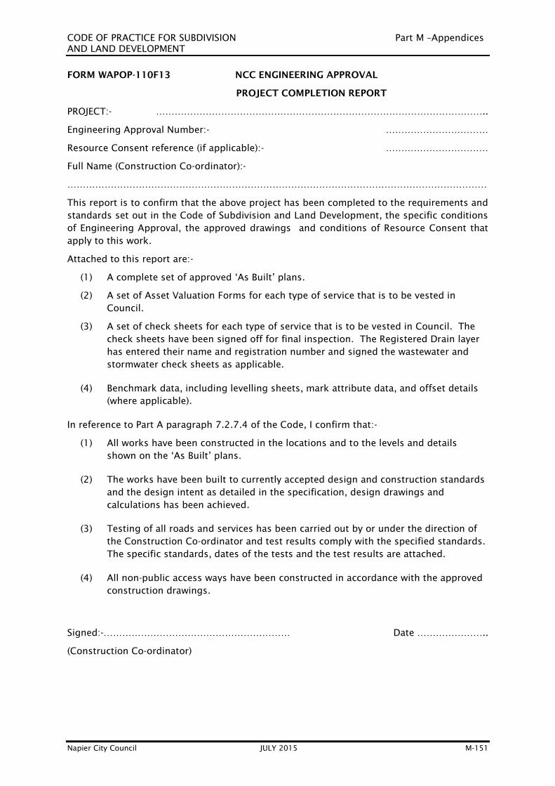
CODE OF PRACTICE FOR SUBDIVISION Part M –Appendices
AND LAND DEVELOPMENT
Napier City Council JULY 2015 M-151
FORM WAPOP-110F13 NCC ENGINEERING APPROVAL
PROJECT COMPLETION REPORT
PROJECT:- ……………………………………………………………………………………………..
Engineering Approval Number:- ……………………………
Resource Consent reference (if applicable):- ……………………………
Full Name (Construction Co-ordinator):-
………………………………………………………………………………………………………………………
This report is to confirm that the above project has been completed to the requirements and
standards set out in the Code of Subdivision and Land Development, the specific conditions
of Engineering Approval, the approved drawings and conditions of Resource Consent that
apply to this work.
Attached to this report are:-
(1) A complete set of approved ‘As Built’ plans.
(2) A set of Asset Valuation Forms for each type of service that is to be vested in
Council.
(3) A set of check sheets for each type of service that is to be vested in Council. The
check sheets have been signed off for final inspection. The Registered Drain layer
has entered their name and registration number and signed the wastewater and
stormwater check sheets as applicable.
(4) Benchmark data, including levelling sheets, mark attribute data, and offset details
(where applicable).
In reference to Part A paragraph 7.2.7.4 of the Code, I confirm that:-
(1) All works have been constructed in the locations and to the levels and details
shown on the ‘As Built’ plans.
(2) The works have been built to currently accepted design and construction standards
and the design intent as detailed in the specification, design drawings and
calculations has been achieved.
(3) Testing of all roads and services has been carried out by or under the direction of
the Construction Co-ordinator and test results comply with the specified standards.
The specific standards, dates of the tests and the test results are attached.
(4) All non-public access ways have been constructed in accordance with the approved
construction drawings.
Signed:-…………………………………………………… Date …………………..
(Construction Co-ordinator)

CODE OF PRACTICE FOR SUBDIVISION Part M –Appendices
AND LAND DEVELOPMENT
Napier City Council JULY 2015 M-152
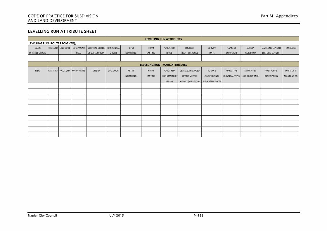
CODE OF PRACTICE FOR SUBDIVISION Part M –Appendices
AND LAND DEVELOPMENT
Napier City Council JULY 2015 M-153
LEVELLING RUN ATTRIBUTE SHEET
LEVELLING RUN (ROUTE FROM - TO);
NAME NCC SUFI# LINZ CODE EQUIPMENT VERTICAL ORDER HORIZONTAL HBTM HBTM PUBLISHED SOURCE/ SURVEY NAME OF SURVEY LEVELLING LENGTH MISCLOSE
OF LEVEL ORIGIN USED OF LEVEL ORIGIN ORDER NORTHING EASTING LEVEL PLAN REFERENCE DATE SURVEYOR COMPANY (RETURN LENGTH)
NEW EXISTING NCC SUFI# MARK NAME LINZ ID LINZ CODE HBTM HBTM PUBLISHED LEVELLED/REDUCED SOURCE MARK TYPE MARK GNSS POSITIONAL LOT & DP #
NORTHING EASTING ORTHOMETRIC ORTHOMETRIC /SUPPORTING (PHYSICAL TYPE) (GOOD OR BAD) DESCRIPTION ADJACENT TO
HEIGHT HEIGHT (MSL +10m) PLAN REFERENCES
LEVELLING RUN - MARK ATTRIBUTES
LEVELLING RUN ATTRIBUTES
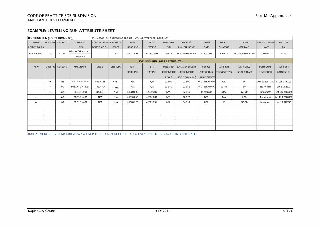
CODE OF PRACTICE FOR SUBDIVISION Part M –Appendices
AND LAND DEVELOPMENT
Napier City Council JULY 2015 M-154
EXAMPLE: LEVELLING RUN ATTRIBUTE SHEET
NAME NCC SUFI# LINZ CODE EQUIPMENT VERTICAL ORDER HORIZONTAL HBTM HBTM PUBLISHED SOURCE/ SURVEY NAME OF SURVEY LEVELLING LENGTH MISCLOSE
OF LEVEL ORIGIN USED OF LEVEL ORIGIN ORDER NORTHING EASTING LEVEL PLAN REFERENCE DATE SURVEYOR COMPANY (1 WAY) (m)
Leica NA704 Auto level
SN34450
NEW EXISTING NCC SUFI# MARK NAME LINZ ID LINZ CODE HBTM HBTM PUBLISHED LEVELLED/REDUCED SOURCE MARK TYPE MARK GNSS POSITIONAL LOT & DP #
NORTHING EASTING ORTHOMETRIC ORTHOMETRIC /SUPPORTING (PHYSICAL TYPE) (GOOD OR BAD) DESCRIPTION ADJACENT TO
HEIGHT HEIGHT (MSL +10m) PLAN REFERENCES
a 339 PIN 18 SO 478094 44174753 CT3Y N/A N/A 12.600 12.600 NCC INTRAMAPS Bolt N/A over street sump Pt Lot 1 DP112
a 340 PIN 19 SO 478094 44174754 CT3Z N/A N/A 12.860 12.861 NCC INTRAMAPS SS Pin N/A Top of kerb Lot 1 DP2173
a N/A 01.01.15.001 3654011 N/A 816000.00 420000.00 N/A 12.869 DP450000 OMA GOOD In footpath Lot 1 DP500000
a N/A 01.01.15.002 N/A N/A 816100.00 420100.00 N/A 12.872 N/A MA BAD Top of kerb Lot 11 DP500000
a N/A 01.01.15.003 N/A N/A 816602.76 420990.51 N/A 14.653 N/A IT GOOD In footpath Lot 1 DP10796
ABC SURVEYS LTD 3000m 0.006
LEVELLING RUN (ROUTE FROM - TO); SS43 - BDA3 SALE ST/MARINE PDE INT - LATHAM ST/GEORGES DRIVE INT
NOTE; SOME OF THE INFORMATION SHOWN ABOVE IS FICTITIOUS. NONE OF THE DATA ABOVE SHOULD BE USED AS A SURVEY REFERENCE.
366 CT3X 1 6 816374.07 421055.850
LEVELLING RUN - MARK ATTRIBUTES
15.972 NCC INTRAMAPS 42005.000 J.SMITHSS 43 SO4877

CODE OF PRACTICE FOR SUBDIVISION Part M –Appendices
AND LAND DEVELOPMENT
Napier City Council JULY 2015 M-155
M2. STANDARD DETAILS – ROADING
Drawing No. Description
M2.1 Standard Rural Road Cross Sections
M2.2 Standard Urban Road Cross Sections – Residential
M2.3 Standard Urban Road Cross Sections – Commercial
M2.4 Standard Urban Road Cross Sections - Industrial
M2.5 Shared Pedestrian & Cycle Accessway & Service Lane Cross Sections
M2.6 Minimum Dimensions for Urban Residential Non-Public Accessways
M2.7 Urban Vehicle Crossing VC1 and VC2 Residential
M2.8 Urban Vehicle Crossing VC3 and VC4 Commercial and Industrial
M2.9 Mountable Kerb Vehicle Crossing VC5
M2.10 Chequer Plate Crossing VC6
M2.11 RVC.1 Rural Vehicle Crossing
M2.12 RVC.2 Rural Vehicle Crossing
M2.13 RVC.3 Rural Vehicle Crossing
M2.14 RVC.4 Rural Vehicle Crossing
M2.15 Standard Corner Layout with Pram Crossings
M2.16 Standard Pram Crossing
M2.17 Standard Sign Installation
M2.18 Standard 4.5m Berm Details
M2.19 Standard Kerb Profiles
M2.20 Standard Dish Channels Details
M2.21(a) Standard Single Road Sump (with Non-Mountable Kerb)
M2.21(b) Standard Double Road Sump
M2.21(c) Standard Single Road Sump (with Mountable Kerb)
M2.22 Alternative Back sump with non-mountable Kerb
M2.23 (a) Standard Stormwater Sump Grate
M2.23 (b) Stormwater Sump Grate (for use on steep grades only)
M2.24 Typical Subsoil Drain Details
M2.25 Road Name Plate Locations
M2.26 Road Name Plate Mounting
M2.27 Typical Street Light Configuration and Arrangement for Urban Roads
M2.28 3.0m and 3.5m Bus Bays
M2.29 Dimensions of Cul-de-sac Turning Areas
M2.30 Alternative Residential Cul-de-sac Details
M2.31 T and Y Turning Heads
M2.32 Turning Areas for Private Roads and Accessways
M2.33 Maximum Breakover Angles for Vehicle Crossings
M2.34 Standard Trench Details
M2.35 Rural Road/Accessway Entrance – Edge Protection for Drain Depth 1.0m
M2.36 Cross-section Guidelines for Verges on Rural Roads
M2.37 Cyclist Facility Design Guide
M2.38 Cyclist Holding Rail and Bike Stand Details
M2.38 (a) Cyclist Deflection Rail Detail
M2.39 Motor Vehicle Rail Barrier
M2.40 Stormwater Connection to Kerb and Channel

CODE OF PRACTICE FOR SUBDIVISION Part M –Appendices
AND LAND DEVELOPMENT
Napier City Council JULY 2015 M-156
Drawing No. Description
M2.41( a) High Capacity Hillside Road Sump Details 1 of 2
M2.41( b) High Capacity Hillside Road Sump Details 2 of 2
M2.41 (c) High Capacity Road Sump for Flat Areas
M2.42 (a) Paved Threshold Details
M2.42 (b) Paved Raised Platform
M2.43 Pedestrian and Splitter Island
M2.44 Pavement Joint Details
M2.45 Precast Sump Block for Standard Kerb
M2.46 Precast Sump Block for Mountable Kerb
M2.47 Tree Planter And Root Director Detail
M2.48 Prohibited Locations of Driveways
M2.49 Paved Threshold Paver Layout

REVISION
NAPIER CITY COUNCIL + WORKS ASSET DEPARTMENT
CREATED
AMENDED
Apr 02
STANDARD RURAL ROAD CROSS-SECTIONS SCALE
NOT TO
M2.1Mar 14
B
*
*
*
*
1
5
*
5
1
5
1
ARTERIAL (<4000 VPD)
COLLECTOR (<2000 VPD or <200 DUs)
MAJOR LOCAL (Up to 500 VPD or < 50 DUs)
(Up to 150 VPD or < 18 DUs)
MINOR LOCAL
stripGravel100mm
stripGravel100mm
C/L
-3% -3%
stripGravel100mm
-3%-3%
C/L
stripGravel100mm
stripGravel100mm
stripGravel100mm
stripGravel100mm
stripGravel100mm
Invert 150mm below subgrade level or 500mm below seal edge whichever is the greater.
-3%-3%
-3% -3%
C/L
C/L
5
1
Max2
1
1
5
1
Max
1/2
1/2
1
Max
Max2
1
2
1
Max
1/2
Max1
Max 2
1
5
1
5
1
5
11
Max
1/2
appropriateEdgeline where
Edgeline
shoulderSealed
shoulderSealed
Whole numbers = mm. Decimalised numbers = m.NOTE:
Seal width
Seal width
Seal width
EdgelineshoulderSealed
shoulderSealed Traffic Lane Traffic Lane
Traffic Lane Traffic Lane
Traffic Lane Traffic Lane
Traffic Lane Traffic Lane
Pavement layers
Pavement layers
Pavement layers
Pavement layers
3.503.50
Subgrade level
3.003.00
6.0VergeBerm
200
7.0VergeBerm
200
7503.503.50750
8.50VergeBerm
10.0VergeBerm
1.503.503.501.50

Boundary
Boundary
Boundary
Boundary
Boundary
Boundary
-3% -3%
-3% -3%
-3% -3%
(Ref. M2.18Berm & FootpathParkingCycleTraffic LanesTraffic LanesCycleParking
(Ref. M2.18Berm & Footpath
(Ref. M2.18Berm & Footpath
(Ref. M2.18Berm & Footpath
(Ref. M2.18Berm & Footpath
(Ref. M2.18Berm & Footpath
MAJOR LOCAL (<125 DUs OR <1500 VPD)
MINOR LOCAL (<25 DUs OR <200 VPD)
ARTERIAL PRINCIPAL & COLLECTOR
REVISION
NAPIER CITY COUNCIL + WORKS ASSET DEPARTMENT
CREATED
AMENDEDRESIDENTIAL
STANDARD URBAN ROAD CROSS-SECTIONSSCALE
NOT TOJul 01
Boundary
Mar 14 M2.2B
4.504.50 (4.00)4.50 (4.00)4.50
9.00 (8.00)
23.60
14.60
4.502.001.803.503.501.802.004.50
18.0m with through traffic (17.0m without through traffic)
13.50
4.503.003.003.00
6.00
Whole numbers = mm. Decimalised numbers = m.NOTE:

REVISION
NAPIER CITY COUNCIL + WORKS ASSET DEPARTMENT
CREATED
AMENDED SCALE
NOT TOJul 01
M2.3COMMERCIAL
STANDARD URBAN ROAD CROSS-SECTIONSMar 14
B
ARTERIAL, PRINCIPAL, COLLECTOR ROAD
LOCAL ROAD
(Commercial)
(Commercial)
Boundary
Boundary
Boundary
Boundary
-3% -3%
-3% -3%
Footpath Footpath
FootpathFootpath
Traffic Lane Traffic Lane ParkingCycleCycleParking
Pavement layers
Pavement layers
Whole numbers = mm. Decimalised numbers = m.NOTE:
20.60
3.002.001.803.503.501.802.03.00
17.00
3.005.505.503.00
14.60
11.00
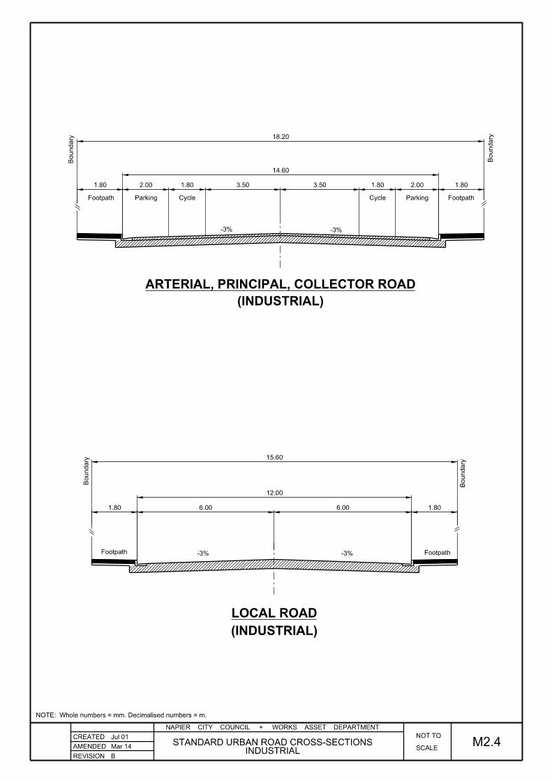
REVISION
NAPIER CITY COUNCIL + WORKS ASSET DEPARTMENT
CREATED
AMENDED SCALE
NOT TO
INDUSTRIALSTANDARD URBAN ROAD CROSS-SECTIONS
Jul 01
M2.4Mar 14
B
ARTERIAL, PRINCIPAL, COLLECTOR ROAD
LOCAL ROAD
Boundary
Boundary
Footpath Footpath
-3% -3%
Boundary
Boundary
Footpath Footpath-3% -3%
ParkingParking Cycle Cycle
Whole numbers = mm. Decimalised numbers = m.NOTE:
(INDUSTRIAL)
(INDUSTRIAL)
1.806.006.001.80
1.802.001.803.503.501.802.001.80
18.20
14.60
12.00
15.60

REVISION
NAPIER CITY COUNCIL + WORKS ASSET DEPARTMENT
CREATED
AMENDED
Jul 01
M2.5SCALE
NOT TO
May 14
C& SERVICE LANE CROSS SECTIONS
SHARED PEDESTRIAN & CYCLE ACCESSWAY
SERVICE LANE
SHARED PATHWAY PAVEMENT
Boundary
Boundary
-2%
Asphaltic Concrete
Pavement layers
Concrete infill
Whole numbers = mm. Decimalised numbers = m.NOTE:
min. width
Grass
Grass Concrete
Compacted basecourse
2.40
6.60
3.303.30
7.40

REVISION
NAPIER CITY COUNCIL + WORKS ASSET DEPARTMENT
CREATED
AMENDED SCALE
NOT TO
NON-PUBLIC ACCESSWAYSMINIMUM DIMENSIONS FOR URBAN RESIDENTIAL
Jul 01
M2.6Mar 14
B
■ Whole numbers = mm. Decimalised numbers = m.■ Refer to Section F1.12 and Table F-4 for design and surfacing requirements.
NOTES:
NO KERB
ONE KERB
TWO KERBS
NO KERB
ONE KERB
TWO KERBS
SERVING 2 to 3 LOTS.
SERVING 4 to 8 LOTS.
ONE NIB & ONE KERB
100
-2% -2%
-2%
-2% -2%
-2% -2% -2% -2%
-2%-2%
(6m Residential Rural)4.80 250250
250
250150
250 250
250
3.00
3.25
3.00
3.50
3.00
4.80 5.30
5.05
4.80
5.30
4.80

REVISION
NAPIER CITY COUNCIL + WORKS ASSET DEPARTMENT
AMENDED
Jul 01
NOTES:
TYPE DESCRIPTION REINFORCINGDEPTH "D"CONCRETE
VC 1
VC 2
1 Dwelling
2 to 3 Dwellings
100mm
125mm
NO
NO
M2.7SCALE
NOT TO
F
CREATED
NOTES: Whole numbers = mm. Decimalised numbers = m.
Refer to Std Dwg M2.33 for driveway profile limits8.
above the invert of channel to control stormwater.
the crossing shall ramp up at least 130mm
Where the adjacent property is below the road level,7.
vehicular traffic.Splay angles shall be 45°.
balance of the footpath is capable of withstanding
1.2m concrete ramp may be installed provided the
Where the footpath is full width (boundary to kerb) a6.
the splay angles shall be 45°.
Where the footpath abuts the back of kerb 5.
widths shall be 1.2m max.
grass berms shall have a splay angle of 1:4, splay
The splay on residential crossings within full width4.
the ramp does not encroach into the footpath
The splay width maybe reduced to 0.6m where3.
requirements are not exceeded.
it is in good order and the maximum grade
The existing footpath may be retained where2.
path and the path altered to suit.
kerb should extend to the boundary side of the
is less than 1 metre the crossing grade from the
Where the distance between the kerb and path1.
RESIDENTIALURBAN VEHICLE CROSSING VC1 and VC2
August 15
Carriageway
Kerb face
"D"
Pro
perty B
oundary
ChannelKerb &
1 in 50 (2%)
25mm step
CROSS SECTION A-A
(12.50%)1 in 8 max
1.101.4m footpath2.00
Sawcut channelinvert to remove kerb
100mm (min.)Compacted AP40 Metal
Grass berm.
A
A
Property Boundary
1:8
maxslo
pe
25
mm
code Part F1.6.14.3
Refer to
Refer to Note 2
required for jointing.sawcut, whereFootpath to be
(Refer to cross section)for jointing.
Sawcut kerb
Refer to Note 1
for depthRefer to table below
Concrete Slab 20MPa
Footpath
600min
1200m max
600min
1200 max

REVISION
NAPIER CITY COUNCIL + WORKS ASSET DEPARTMENT
CREATED
AMENDED SCALE
NOT TO
M2.8Jul 01
ECOMMERCIAL AND INDUSTRIAL.
URBAN VEHICLE CROSSING VC3 AND VC4August 15
DESCRIPTION REINFORCINGTYPE
Replace Kerb & channel
Property Boundary
Concrete vehicle crossing
Carriageway
665 HRC
Carriageway
Normal Commercial
4 or more Dwellings/VC3
VC4 High Commercial/
Industrial use
150mm
Specific design
(150 mm min)
1 layer
665 mesh
'D'
CONCRETE DEPTH 'D'
A
A
125mm
wide 25mm thick,300mmAsphaltic Concrete basecourse and footpath with M4Sawcut, reinstate
Boundary
Pro
perty
DEPTHSUB-BASE
CROSS SECTION A-A
footpath.Concrete Asphaltic
footpath.Asphaltic Concrete
300
300
Slope 1:8
max
min
1.00
Concrete slab 20mpa
for sub-base depth)(refer to table below,Compacted AP40
665 mesh
2 layers HRC150mm
1 in 8 max
min
1.00
1:8 Slope max
1:8 Slope max
Refer to code Part F1.6.14.3
Refer to standard drawing M2.33 for driveway profile limits 3.
Reinforcing to be HRC 665 2.
Mechanical compaction required.1.
NOTES:
existing kerb & channelSawcut & remove
(see table below)HRC Mesh 150 laps
at invertthickness 150mmMinimum channelKerb & Channel
25mm step
Sawcut
25
mm
Whole numbers = mm. Decimalised numbers = m.NOTE:

REVISION
NAPIER CITY COUNCIL + WORKS ASSET DEPARTMENT
CREATED
AMENDED
Jul 01
M2.9SCALE
NOT TO
Mar 14 MOUNTABLE KERB VEHICLE CROSSING VC5B
maximum grade requirements are not exceeded.Existing footpath may be retained where it is in good order and the 2.
Refer to Standard Drawing M2.31 for driveway profile limits.1.
NOTES:
FootpathVehicle Crossing
Pro
perty B
oundary
Property Boundary
Footpath
A
A
minimum thicknessCompacted AP40 100mm
Carriageway
min
200
100
Kerb & ChannelStandard mountable
Whole numbers = mm. Decimalised numbers = m.NOTE:
Grass Berm.
Refer to code Part F1.6.15
Splays as per VC1 and VC2 options
required for jointingsawcut where
Footpath to be

REVISION
NAPIER CITY COUNCIL + WORKS ASSET DEPARTMENT
CREATED
AMENDED
Jul 01
SECTION A-A
SCALE
NOT TO
M2.10Mar 14
3. Refer to Std Dwg M2.7 for stormwater control.
2. Refer to Std Dwg M2.31 for driveway profile limits.
removed for maintenance and they shall not rattle.1. Steel plates shall be securely fastened, easily
NOTES:
CHEQUER PLATE CROSSING VC6
chequer plate crossingsSpecific design is required for industrial
the approval of the Road Asset ManagerChequer plate crossings may only be installed with
NOTE:
B
Property
boun
dary
A
NOTE:
at appropriate position.Existing seal/asphalt to be sawcut
Maximum length of chequer plates: 1.5mTaper ramp as shown to prevent ponding.
A
min.
for commercial crossings.Mesh reinforcing required
BackfillM4 Basecourse.
Sawcut to remove existing kerb.
D12 Bars
Whole numbers = mm. Decimalised numbers = m.NOTE:
Splays as per VC1, VC2, VC3 and VC4 options
Varies
75 75
150flush surface.Rebates to maintain
Min 8mm thickness.Webco Plate or similar.
flush surface.Rebates to maintain
100300 - 400
180
Note:
Asphaltic Concrete25mm min

REVISION
NAPIER CITY COUNCIL + WORKS ASSET DEPARTMENT
CREATED
AMENDED SCALE
NOT TOJul 01
May 14
C
M2.11RVC 1 - RURAL VEHICLE CROSSING
Edge of seal.
Edge of seal.
Centreline
Operating
100
60
70
80
90
50
40
FRONTAGE ROAD CLASSIFICATION
MINIMUM SIGHT DISTANCE (metres)
Speed
(kph) Distance (m)
Edge line
Edge line
Sight distance Sight distance
110
120 230
190
30
40
130
105
85
55
160 160
65
85
105
130
45
35
190
230 330
290
70
90
210
175
140
115
250
70
80
100
1. COUNCIL ROADS 2. STATE HIGHWAYS
Sight
Minimum
Drain
and sealedArea to be constructed
(kph)
(from centre of lane) (from centre of lane)
B
A
D
E
C
Speed
Operating
140
170
240
*R = 15m for heavy vehicles*R = 9m for light vehicles use (includes single unit truck)
Local Roads
drivewaysLow & high volume
Low volume driveways
Collectors Arterial/ Principal
Low volume driveways
accesswayto match
Min. width
F-4)(Refer Table
* R
* R
the driveway to stop clear of the carriageway while the gate is being opened or closed.
Any gate shall be recessed back from carriageway sufficient distance to allow any vehicle likely to be using5.
The operating speed shall be the 85th percentile speed on the road frontage. (refer Part F1:1.5.4).4.
b) Low and high volume driveways on arterial roads, no obstructions allowed within these sightlines (parked vehicles not excluded)
sight lines (excluding occassional parked vehicles)
a) High volume driveways on collector roads, no permanent obstructions allowed within these
Sight lines CE & DE:
Sight lines AC & BD: No obstuctions allowed within these sightlines.3.
Sight distances shall be measured from a point 1.15 m above the ends of each sight line.2.
Point A, B, C & D shall be on the centre of the lane.1.
NOTES:
5.0
m
Legal Boundary
Sight lines
Sight Lines
MINIMUM SIGHT DISTANCES (ref. Land Transport - RTS6)
refer to section F1 of the Code.Culvert diameter & Headwall

REVISION
NAPIER CITY COUNCIL + WORKS ASSET DEPARTMENT
CREATED
AMENDED RVC 2 - RURAL VEHICLE CROSSING
Jul 01
SCALE
NOT TO
May 14
C
M2.12
Edge of seal.
Centreline
1:10 Taper
Edge of seal.
Sight distance Sight distance
* R
Edge line
Edge line
Speed
(kph)
Operating
250
115
140
175
210
90
70
290
330230
190
35
45
130
105
85
65
160160
55
85
105
130
40
30
190
230120
110
MINIMUM SIGHT DISTANCE (metres)
FRONTAGE ROAD CLASSIFICATION
40
50
90
80
70
60
100
Drain
(from centre of lane)(from centre of lane)
* R
B
AC
D
1. COUNCIL ROADS
accesswayto match
Min. width.
(Refer Table F-4)
E
1:10 Tape
r
*R = 15m for heavy vehicles
*R = 9m for light vehicles use (includes single unit truck)
Local Roads
drivewaysLow & high volume
Low volume driveways
Collectors Arterial/ Principal
Low volume driveways
the driveway to stop clear of the carriageway while the gate is being opened or closed.
Any gate shall be recessed back from carriageway sufficient distance to allow any vehicle likey to be using5.
The operating speed shall be the 85th percentile speed on the road frontage. (refer Part F1:1.5.4).4.
b) Low and high volume driveways on arterial roads, no obstructions allowed within these sightlines (parked vehicles not excluded)
sight lines (excluding occassional parked vehicles)
a) High volume driveways on collector roads, no permanent obstructions allowed within these
Sight lines CE & DE:
Sight lines AC & BD: No obstuctions allowed within these sightlines.3.
Sight distances shall be measured from a point 1.15 m above the ends of each sight line.2.
Point A, B, C & D shall be on the centre of the lane.1.
NOTES:
5.0
m
MINIMUM SIGHT DISTANCES (ref. Land Transport-RTS6)
6.0
m
Area to be permanently surfaced
6.0
m
Sight lineSight lines
Legal boundarysection F1 of the Code.Culvert diameter & headwall refer to

REVISION
NAPIER CITY COUNCIL + WORKS ASSET DEPARTMENT
CREATED
AMENDED RVC 3 - RURAL VEHICLE CROSSING
Jul 01
SCALE
NOT TO
M2.13May 14
C
Edge of seal.
Centreline
15m1:10 taper 35m 1:10 taper
Edge of seal.
Sight distance
(from centre of lane.) (from centre of lane.)
Sight distance
(kph)
100
80
70
2. STATE HIGHWAYS
Sight
Edge line
Edge line
Drain
Distance (m)
Minimum
permanently surfacedArea to be
C
B
A
D
E
Speed
Operating
140
170
240
*R = 15m for heavy vehicle use.
*R = 9m for light vehicles use (includes single unit truck)
Speed
(kph)
Operating
250
115
140
175
210
90
70
160
55
85
105
130
40
30
MINIMUM SIGHT DISTANCE (metres)
FRONTAGE ROAD CLASSIFICATION
40
50
90
80
70
60
100
1. COUNCIL ROADS
Local Roads Collectors Arterial/ Principal
* R
* R
1:10 Taper
drivewaysHigh volume
Low & high volume driveways
(Refer Table F- 4)match accessway
min. width to
250
115
140
175
210
90
70
160
85
105
130
drivewaysLow volume
drivewaysHigh volume
the driveway to stop clear of the carriageway while the gate is being opened or closed.
Any gate shall be recessed back from carriageway sufficient distance to allow any vehicle likely to be using5.
The operating speed shall be the 85th percentile speed on the road frontage. (refer Part F1:1.5.4).4.
b) Low and high volume driveways on arterial roads, no obstructions allowed within these sightlines (parked vehicles not excluded)
sight lines (excluding occassional parked vehicles)
a) High volume driveways on collector roads, no permanent obstructions allowed within these
Sight lines CE & DE:
Sight lines AC & BD: No obstuctions allowed within these sightlines.3.
Sight distances shall be measured from a point 1.15 m above the ends of each sight line.2.
Point A, B, C & D shall be on the centre of the lane.1.
NOTES:
6.0
m
1:10 taper
35
45
65
5.0 m
MINIMUM SIGHT DISTANCES (ref. Land Transport-RTS6)
2.5
m
2.5
m
section F1 of the Code.Culvert diameter & headwall refer to
Legal boundary
Sight Lines
Sight Lines
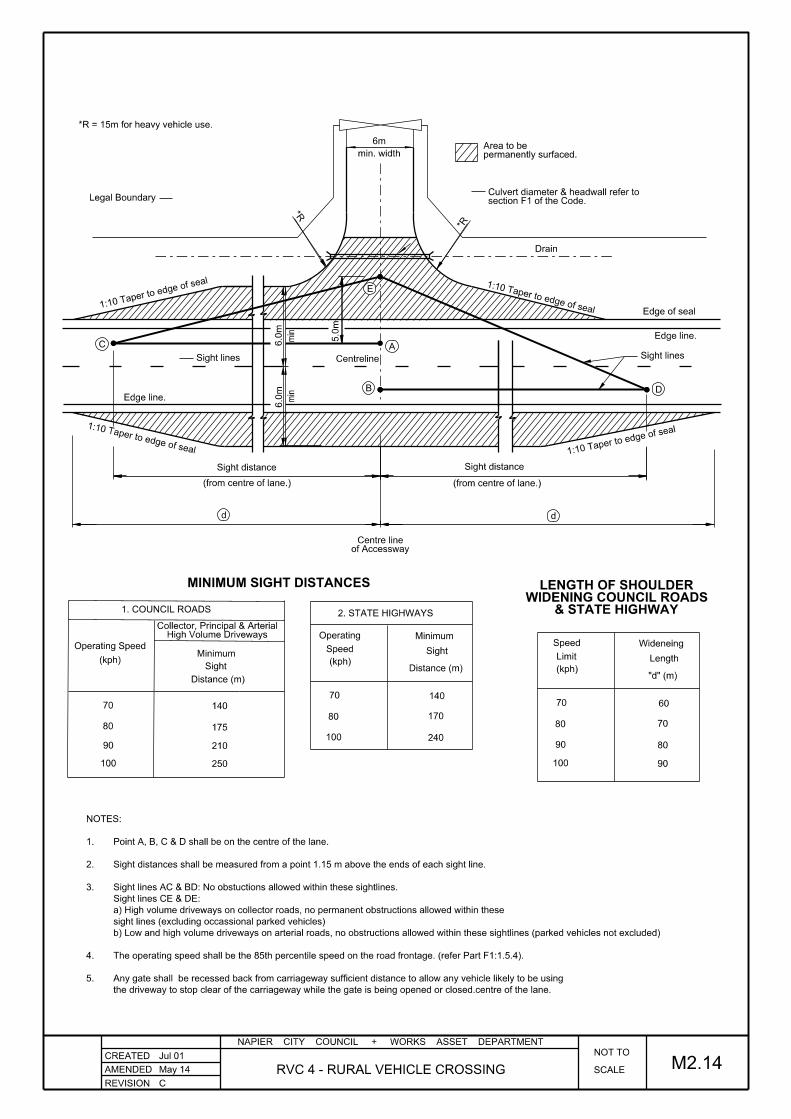
REVISION
NAPIER CITY COUNCIL + WORKS ASSET DEPARTMENT
CREATED
AMENDED SCALE
NOT TO
RVC 4 - RURAL VEHICLE CROSSING
Jul 01
Distance (m)
70
80
(kph)Minimum
Sight
MINIMUM SIGHT DISTANCES
May 14
C
M2.14
(kph)
100
80
70
2. STATE HIGHWAYS
Sight
Distance (m)
Minimum
Speed
Operating
140
170
240
Operating Speed
High Volume DrivewaysCollector, Principal & Arterial
1. COUNCIL ROADS
(kph)
80
70
100
Limit
Speed Wideneing
Length
"d" (m)
60
70
80
90100
90 210
140
175
250
& STATE HIGHWAYWIDENING COUNCIL ROADS
LENGTH OF SHOULDER
90
the driveway to stop clear of the carriageway while the gate is being opened or closed.centre of the lane.
Any gate shall be recessed back from carriageway sufficient distance to allow any vehicle likely to be using5.
The operating speed shall be the 85th percentile speed on the road frontage. (refer Part F1:1.5.4).4.
b) Low and high volume driveways on arterial roads, no obstructions allowed within these sightlines (parked vehicles not excluded)
sight lines (excluding occassional parked vehicles)
a) High volume driveways on collector roads, no permanent obstructions allowed within these
Sight lines CE & DE:
Sight lines AC & BD: No obstuctions allowed within these sightlines.3.
Sight distances shall be measured from a point 1.15 m above the ends of each sight line.2.
Point A, B, C & D shall be on the centre of the lane.1.
NOTES:
6m
Drain
*R
*R
Sight distance
(from centre of lane.)
Centreline
Edge line.
1:10 Taper to edge of seal
Sight distance
(from centre of lane.)
1:10 Tap
er to edg
e of seal 1:10 Taper to edge of seal Edge of seal
Edge line.
1:10 Tape
r to edge o
f seal
min. width
d
of AccesswayCentre line
A
permanently surfaced.Area to be
d
B
E
D
C
min
min
*R = 15m for heavy vehicle use.
6.0
m
5.0
m
6.0
m
Sight lines
section F1 of the Code.Culvert diameter & headwall refer to
Legal Boundary
Sight lines
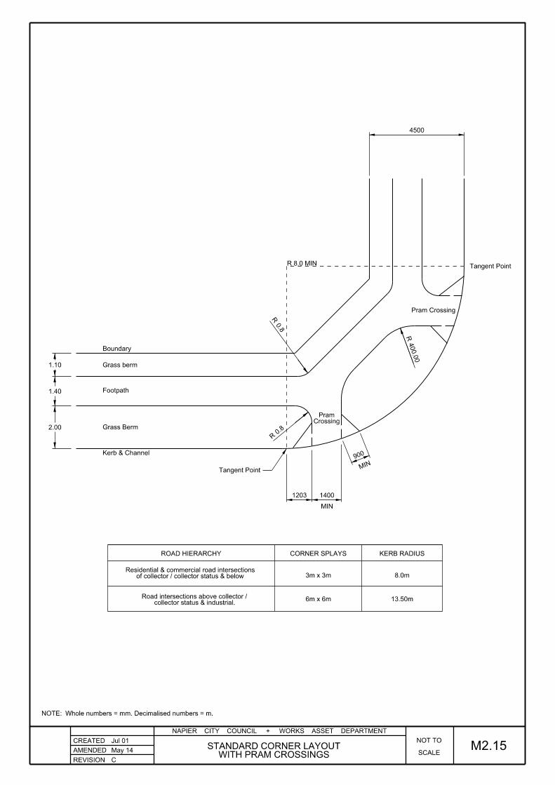
REVISION
NAPIER CITY COUNCIL + WORKS ASSET DEPARTMENT
CREATED
AMENDED M2.15WITH PRAM CROSSINGS
STANDARD CORNER LAYOUTSCALE
NOT TO
May 14
C
Jul 01
2.00
1.40
1.10
Boundary
Grass berm
Footpath
Grass Berm
Kerb & Channel
Tangent Point
Pram Crossing
0.8
R
0.8
R
MIN
CrossingPram
R 8.0 MIN
4500
Tangent Point
400.0
0
R
ROAD HIERARCHY CORNER SPLAYS KERB RADIUS
3m x 3m
6m x 6m
8.0m
13.50m
of collector / collector status & belowResidential & commercial road intersections
collector status & industrial.Road intersections above collector /
Whole numbers = mm. Decimalised numbers = m.NOTE:
MIN
14001203
900

REVISION
NAPIER CITY COUNCIL + WORKS ASSET DEPARTMENT
CREATED
AMENDED SCALE
NOT TO
STANDARD PRAM CROSSING
Jul 01
M2.16May 14
C
BA
SECTION B-B
PLAN
45°45°
100
SECTION A-A
Sawcut to joint
Sloped sides
Boundary
Kerb SplayChannel Invert
1 in 8 max slope.
M4 Basecourse
Varies
1.2
0 min.
1.40 min.
20mm lip
20mm lip
Whole numbers = mm. Decimalised numbers = m.NOTE:
1.5
0 m
ax.
0.8
m min.

REVISION
NAPIER CITY COUNCIL + WORKS ASSET DEPARTMENT
CREATED
AMENDED
May 09
STANDARD SIGN INSTALLATION
GROUND SOCKET FOUNDATION DETAILS
SIGN LOCATIONS
SCALE
OT TON
CONCRETE FOOTPATH& GRASS BERMA/C FOOTPATH
SPLITTER ISLAND
BERM
gro
und
above
NOTE:
IS PROHIBITED
CONCRETE MIX
USE OF RAPID SET
B
M2.17June 15
GIVE
WAY
30 - 5
0
600
300
30 - 5
0
500
300
100
==
2.5
0 min. over fo
otp
ath
500 min.
Also Refer to dwg No. M2.26 for foundation detailsNOTE:
for 60mm Ø pole600mm ground socket
A/C footpath.
Grass berm.
torqued to 18Nm².of the sign face andoriented in the directionGrub screw should be
socket for 60mm Ø pole.400mm aluminum signfix
or galvanised steel pole.60mm ID Aluminium
socket.concrete from enteringStop and preventsCap - Acts as Pole
RG-17ARG-17 or
white powder coated.or galvanised steel pole60mm ID Aluminium fluted
foundation20 MPa concrete300 x 300 square
foundation20 MPa concrete300 x 300 square
concrete footpath.100mm thick
Whole numbers = mm. Decimalised numbers = m.NOTE:
and pole must be 400mm. spacing between kerb face2. For bus stop signs the
on the top end of the pole.1. A plastic cap shall be fitted
NOTE:

REVISION
NAPIER CITY COUNCIL + WORKS ASSET DEPARTMENT
CREATED
AMENDED STANDARD 4.5m BERM DETAILS
Jul 01
M2.18SCALE
NOT TO
May 14
Approval is required from the NCC Road Asset manager.
In constrained conditions the minimum cover to services maybe reduced to 450mm. 3)
Sewer in Centre of Carriageway2)
to a maximum of 20% with the Roading Managers Approval.
Where ground profile dictates the inner berm may be altered from 4%1)
NOTE:
C
200mm
900mm
1.8m
4.50
100 min.
footpath100mm Concrete
2%20% max.4% min.
4%
Water
Boundary
Po
wer
Gas
Teleco
m
750 c
ov
600 c
ov
250 300 450
LV
Spare
HV
2.00 1.40 1.10
AP40 basecourse100mm min.
HV 1
100 c
ov
LV 6
00 c
ov
Stormwater
Whole numbers = mm. Decimalised numbers = m.NOTE:
0mm
(See *Note)+325max.+150 min.
+105
+75mm
polelightStreet
100mm topsoil
100mm topsoil

REVISION
NAPIER CITY COUNCIL + WORKS ASSET DEPARTMENT
CREATED
AMENDED STANDARD KERB PROFILES
Jul 01
to be rounded R=25mmExposed edgesExcept where noted
M2.19
Minor dimensional variations to kerb & channel may be approved by the Road Asset Manager.2.
Crack control joints shall be sawcut at 6.0m intervals to coincide with every second footpath joint if kerb is adjacent to footpath.1.
NOTES:
SCALE
NOT TO
Mar 14
B
KERB & CHANNEL
min.
300145
10
20
R 20
Length = 590mm
Road Asset Division.where specifically approved by Council'sKerb blocks are only to be used
KERB BLOCK
PRECAST, ISLAND
min.*
NIB
8
10
min.*
55R 30
R 20
to be rounded R=20mmExposed edgesExcept where noted
MODIFIED NIB
KERB & CHANNEL DETAIL
STANDARD MOUNTABLE
*
procedures
Refer to part F for CBR design
weak subgrades.
high traffic flows / heavy traffic /
* To be increased at locations with
Whole numbers = mm. Decimalised numbers = m.NOTE:
125
105
145
90
445200
150235
200
Sub-baseSub-grade
40
200
30120
90
10mm Mortar Bed
165160
140
145
105
260
200
325200 Sub-grade
Sub-base
520200
165
130 30050
40
58
30
200
220
Sub-grade
Sub-base
200
150
125
225
130
5
90
(where required)
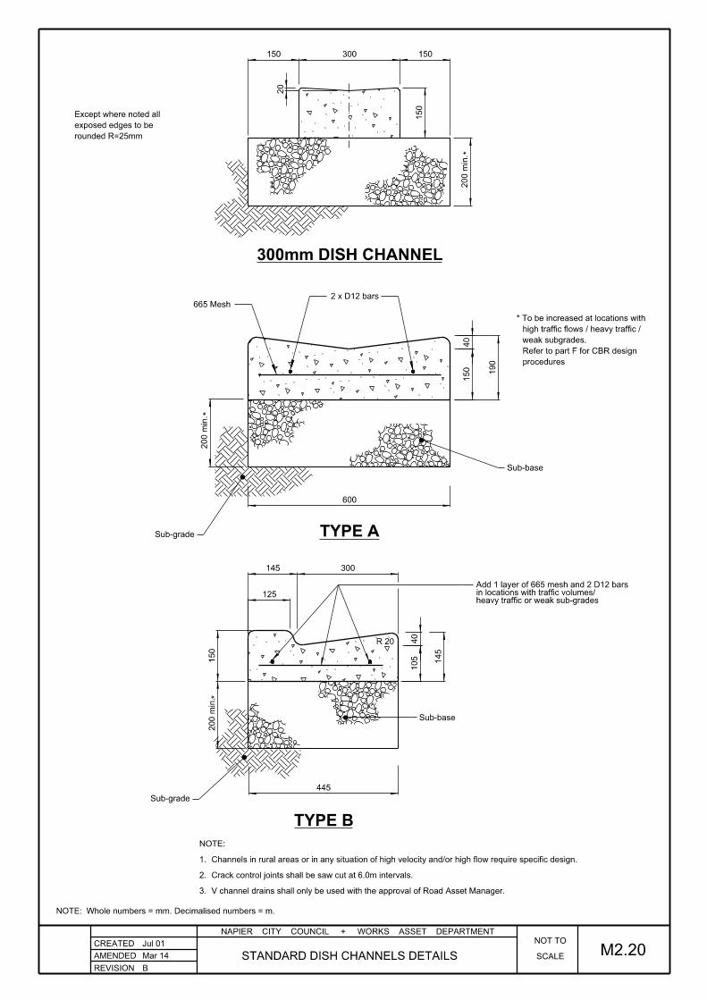
REVISION
NAPIER CITY COUNCIL + WORKS ASSET DEPARTMENT
CREATED
AMENDED STANDARD DISH CHANNELS DETAILS
Jul 01
TYPE A
TYPE B
M2.20
600
445
190
150
300145
125
105 145
150
200 min.
200 min.
R 20
300mm DISH CHANNEL
2 x D12 bars 665 Mesh
Mar 14
B
procedures
Refer to part F for CBR design
weak subgrades.
high traffic flows / heavy traffic /
* To be increased at locations with
**
V channel drains shall only be used with the approval of Road Asset Manager.3.
Crack control joints shall be saw cut at 6.0m intervals.2.
Channels in rural areas or in any situation of high velocity and/or high flow require specific design.1.
NOTE:
*
rounded R=25mm
exposed edges to be
Except where noted all
SCALE
NOT TO
40
40
150
150300150
Sub-base
Sub-grade
Sub-grade
Sub-base
heavy traffic or weak sub-gradesin locations with traffic volumes/Add 1 layer of 665 mesh and 2 D12 bars
20
Whole numbers = mm. Decimalised numbers = m.NOTE:
200 min.
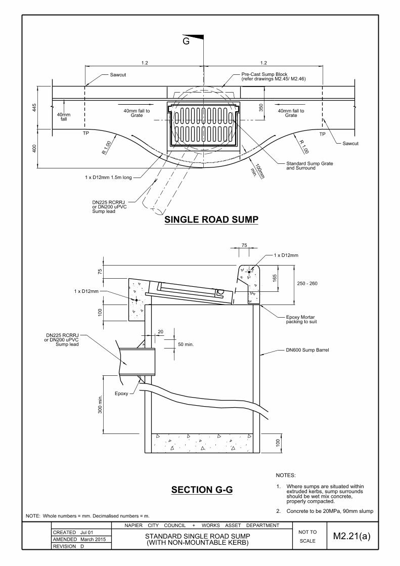
REVISION
NAPIER CITY COUNCIL + WORKS ASSET DEPARTMENT
CREATED
AMENDED
Jul 01
SINGLE ROAD SUMP
SECTION G-G
fall 40mm Grate
40mm fall toGrate
40mm fall to
100
mm
min.
TP TP
G
NOTES:
300 min.
100
75
20
50 min.
165
250 - 260
350
400
445
Sawcut
Epoxy
M2.21(a)D
Concrete to be 20MPa, 90mm slump2.
properly compacted.should be wet mix concrete,extruded kerbs, sump surroundsWhere sumps are situated within1.
100
1.21.2
(WITH NON-MOUNTABLE KERB)STANDARD SINGLE ROAD SUMP
March 2015 SCALE
NOT TO
1.0
0
RR 1.0
0
and SurroundStandard Sump Grate
1 x D12mm 1.5m long
Sawcut
1 x D12mm
75
Whole numbers = mm. Decimalised numbers = m.NOTE:
1 x D12mm
Sump leador DN200 uPVCDN225 RCRRJ
packing to suitEpoxy Mortar
Sump leador DN200 uPVCDN225 RCRRJ
DN600 Sump Barrel
(refer drawings M2.45/ M2.46)Pre-Cast Sump Block
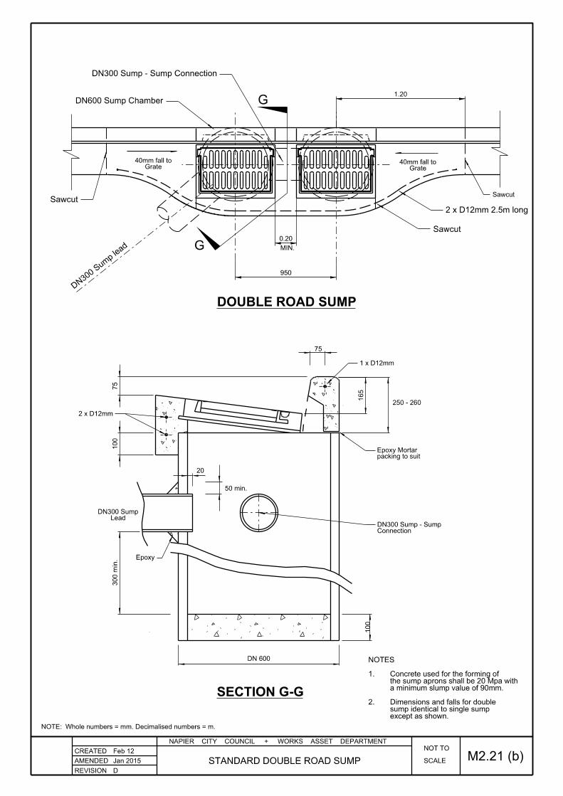
MIN.
DN30
0 Sum
p lead
950
0.20
1.20
2 x D12mm 2.5m long
Sawcut
DN600 Sump Chamber
DN300 Sump - Sump Connection
Sawcut
REVISION
NAPIER CITY COUNCIL + WORKS ASSET DEPARTMENT
CREATED
AMENDED SCALE
NOT TO
M2.21 (b)Feb 12
STANDARD DOUBLE ROAD SUMP D
SECTION G-G
DOUBLE ROAD SUMP
300 min.
100
75
20
50 min.
165
250 - 260
Epoxy
DN 600
G
except as shown.sump identical to single sumpDimensions and falls for double2.
a minimum slump value of 90mm.the sump aprons shall be 20 Mpa with Concrete used for the forming of 1.
NOTES
G
Jan 2015
100
Grate40mm fall to
Sawcut
Grate40mm fall to
Whole numbers = mm. Decimalised numbers = m.NOTE:
1 x D12mm
packing to suitEpoxy Mortar
75
2 x D12mm
LeadDN300 Sump
ConnectionDN300 Sump - Sump

REVISION
NAPIER CITY COUNCIL + WORKS ASSET DEPARTMENT
CREATED
AMENDED
SINGLE ROAD SUMP
SECTION G-G
100
mm
min.
TP TP
G
NOTES:
300 min.
100
20
50 min.
350
400
445
Sawcut
Epoxy
M2.21(c)A
Concrete to be 20MPa, 90mm slump2.
properly compacted.should be wet mix concrete,extruded kerbs, sump surroundsWhere sumps are situated within1.
100
1.21.2
March 2015(WITH MOUNTABLE KERB)
STANDARD SINGLE ROAD SUMP
150
45
slope target 15% (8.5°)
March 2015
Grate62mm fall to
Grate62mm fall to
SCALE
NOT TO
fall 33mm
1.0
0
RR 1.0
0
and SurroundStandard Sump Grate
1 x D12mm 1.5m long
Sawcut
1 x D12mm
Whole numbers = mm. Decimalised numbers = m.NOTE:
1 x D12mm
Sump leador DN200 uPVCDN225 RCRRJ
packing to suitEpoxy Mortar
Sump leador DN200 uPVCDN225 RCRRJ
DN600 Sump Barrel
(refer drawings M2.45/ M2.46)Pre-Cast Sump Block

REVISION
NAPIER CITY COUNCIL + WORKS ASSET DEPARTMENT
CREATED
AMENDED
Aug 96
Kerb
Channel
SECTION
FRONT ELEVATION
PLAN
M2.22
600Ø Sump barrel
SCALE
NOT TO
below top of kerb.barrel to be 150mmTop of sump1.
TO SET UP:
or similar.& smooth off with Eparto achieve 100mm gapBreak out sump barrelMin. gap = 100 x 400mmInlet:
Mar 14
BNON-MOUNTABLE KERB
ALTERNATIVE BACK SUMP WITH
150
400
100
400 300300
100150
(Dimensions differ)shown in background.kerb & channelNon-mountable
Channel invert
chainattachmentL section &50 x 50 x 6
Kerb (Non-mountable)
Kerb face
Precast lid
channel into sump.Increase fall across
HD 12 25mm cov.
HD 16 25mm cov.
Precast lid
40mm Chamfer @ 45°
cleaning accessfor inspection &Galvanised lid470 x 470 x 8
Whole numbers = mm. Decimalised numbers = m.NOTE:
with the approval of the NCC Road Asset Manager
The alterative back sump may only be installed2)
Sump to be used in CBD and Rural areas only.1)
NOTE:

REVISION
NAPIER CITY COUNCIL + WORKS ASSET DEPARTMENT
CREATED
AMENDED SCALE
NOT TOApr 10
May 14 M2.23(a)STANDARD STORMWATER SUMP GRATEC
A
A
BB
44mm
32
mm
C
C
DD
647
60964 64
64
16 16
18
705
737
647
56
12
41
64
56
19
12
25
39
18
508
38
403
44
695
635
32
635
FRAME
GRATE
SECTION A-A
SECTION B-B
SECTION C-C
SECTION D-D
29
29
27
30
30
25
HINGE
Whole numbers = mm. Decimalised numbers = m.NOTE:
28
38
25.530
22
415
64
Hinge

REVISION
NAPIER CITY COUNCIL + WORKS ASSET DEPARTMENT
CREATED
AMENDED SCALE
NOT TOApr 10
Mar 14 M2.23(b)B
(FOR USE ON STEEP GRADES ONLY)STORMWATER SUMP GRATE
Hinge
A
A
BB
44mm
32
mm
C
C
DD
647
64 64
64
16 16
705
737
647
56
12
41
64
56
19
12
25
39
18
508
76
403
44
695
635
635
FRAME
GRATE
SECTION A-A
SECTION B-B
SECTION C-C
SECTION D-D
29
25
19
29
25
HINGE
Whole numbers = mm. Decimalised numbers = m.NOTE:
19
25
76
415
64
32
18
609

REVISION
NAPIER CITY COUNCIL + WORKS ASSET DEPARTMENT
CREATED
AMENDED TYPICAL SUBSOIL DRAIN DETAILS
Jul 01
on Filter Fabric
min R
oad M
etal
Level
below lowest Subgrade
Min of 200mm
Filter Fabric
UNDER KERB DRAINAGE
RURAL SUBSOIL DRAINAGE
M2.24SCALE
NOT TO
surface.
subgrade
below road
300 min.
Carriageway
C
May 14
200mm
100
500 min.
310 min.
100
100
with Filter Sock
Alkathene Subsoil Drain
110 Dia slotted PVC or
110 Dia Subsoil Pipe
Basecourse
Material
Approved Drainage
Approved drainage material
Filter Layer if required
Basecourse
Sub-base
Subgrade
Subgrade
Whole numbers = mm. Decimalised numbers = m.NOTE:

REVISION
NAPIER CITY COUNCIL + WORKS ASSET DEPARTMENT
CREATED
AMENDED
A
Jul 07 SCALE
NOT TO
ROAD NAME PLATE LOCATIONS
Jul 01
M2.25
Signing for Arterial / Local and Arterial/Arterial Intersections
(Where one Arterial is Dual Carriageway)
(Where both Arterial is Dual Carriageway)
Signing for Arterial / Arterial Intersections

REVISION
NAPIER CITY COUNCIL + WORKS ASSET DEPARTMENT
CREATED
AMENDED SCALE
NOT TO
ROAD NAME PLATE MOUNTING
Jul 01
Ground Level
Background Material:Blade Material:Blade Depth:Letter Colour:Letter Spacing:Letter Style:Letter Height:
Reflectorised BlueAluminium Extrusion159mm and 200mmReflectorised WhiteA.S. 1744 MediumSeries C100mm
M2.26
NOTES:
Mar 14
B
3.0
0
600
300
NOTE: Also refer to dwg No. M2.38 for foundation details.
Not less than 159mm for all others.2.
Not less than 200mm for CBD, Arterials and Principal Roads.1.
Plate Sizes:
is mounted.end of the pole where no cross road signA plastic cap shall be fitted on the top1.
NOTE:
Pole cap.
M10 Grub screw (Stainless Steel)
white powder coated.or aluminium fluted pole60mm ID galvanised steel
Aluminium signfix socket for 60mm pole.
concrete foundation.300 x 300 square 20 MPa
Whole numbers = mm. Decimalised numbers = m.NOTE:

REVISION
NAPIER CITY COUNCIL + WORKS ASSET DEPARTMENT
CREATED
AMENDEDAND ARRANGEMENT FOR URBAN ROADSTYPICAL STREET LIGHT CONFIGURATION
Jul 01
M2.27SCALE
NOT TO
C
June 15
150w or 250w Lantern
(or Lantern to suit Design Criteria)
Set Back(s)
of Road Lighting Pole
Parking Lane
or Shoulder Traffic Lanes
Standard Outreach
(or Lantern to suit Design Criteria)
Traffic L
anes
Carria
ge
way
Verge
Parking Lane or Shoulder
Sealed or Unsealed
Set
Back
Set
Back
Kerb
Kerb
Road
Lighting Pole
Verge
Kerb
Refer to Appendix B, AS/NZS1158.1.3
min 400mm
7.3m galvanised steel pole
35w metal Halide Lantern
Actual Spacing must satisfy the Design Criteria listed in the StandardsNote that this Pole Spacing is only a guide
50 - 80m for Local Roads40-50m for Arterial and Collector Roads
10m Galvanised Steel Pole
ARTERIAL ROADS SET BACK LAYOUTAND LOCAL ROADS
COLLECTOR
TYPICAL STAGGERED ARRANGEMENT

REVISION
NAPIER CITY COUNCIL + WORKS ASSET DEPARTMENT
CREATED
AMENDED 1:200
SCALEJul 01
M2.283.0m AND 3.5m BUS BAYS
o/s 220mm
o/s nil
o/s 840mm
o/s 3.08m
o/s 3.39m
o/s 3.5m
o/s 3.5m
o/s 3.22m
o/s 2.34m
o/s 610mm
o/s nilo/s nil
o/s 560mm
o/s 2m
o/s 2.74m
o/s 3m
o/s 3m
Bus Sto
pped
o/s 2.89m
o/s 2.58m
o/s 860mm
o/s 220mm
o/s nil
Parkin
g w
hen
Permitte
d
Parkin
g w
hen
Permitte
d
Parkin
g P
ermitte
dKerbline if
Kerbline if
Parkin
g n
ot
Permitte
d
Parkin
g w
hen
Permitte
d
Parkin
g P
ermitte
d
Kerbline if
Permitte
d
Parkin
g n
ot
Kerbline if
Parkin
g w
hen
Permitte
d
+ 1
2.0
0 for each e
xtra B
us
+ 1
2.0
0 for each e
xtra B
us
Mar 14
B
3.5
m B
US B
AY
3m B
US B
AY
3.50
1.50
2.4
82.2
14.4
24.9
62.9
42.8
07.4
71.4
01.4
7
2.0
0
2.3
02.0
64.1
44.6
02.9
42.8
05.8
01.4
01.4
7
1.0
0
3.00
1.00
14.6
18.0
0 for
One B
us
11.5
9
20.00
R20.00R
20.00R
20.00 R
10.00
R10.00R
10.00
R
Bus e
dge.
Line of
Offset fro
m this Line.
Bus e
dge.
Line of
Offset fro
m this Line.
14.6
114.0
0 for
One B
us
10.8
0
Whole numbers = mm. Decimalised numbers = m.NOTE:
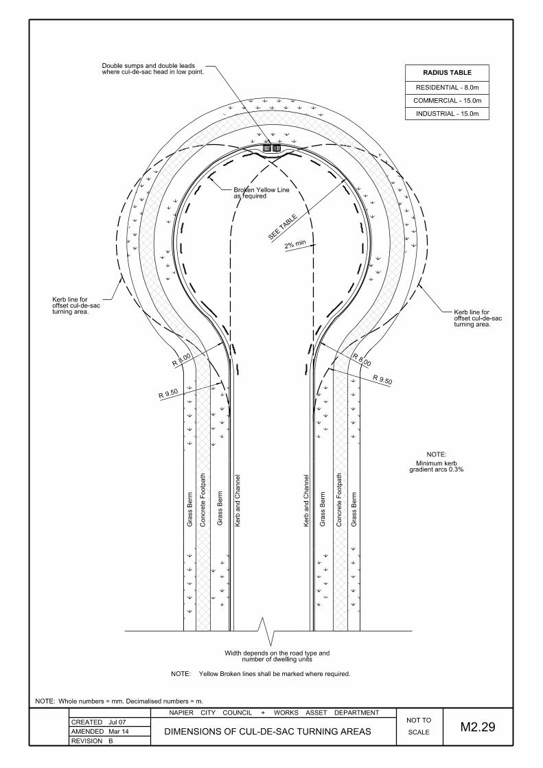
REVISION
NAPIER CITY COUNCIL + WORKS ASSET DEPARTMENT
CREATED
AMENDED SCALE
NOT TOJul 07
DIMENSIONS OF CUL-DE-SAC TURNING AREAS
RADIUS TABLE
2% min
8.00
R
9.50R
9.50R
8.00
R
Grass B
erm
Concrete F
ootp
ath
Grass B
erm
Kerb a
nd C
hannel
Kerb a
nd C
hannel
Grass B
erm
Concrete F
ootp
ath
Grass B
erm
RESIDENTIAL - 8.0m
COMMERCIAL - 15.0m
INDUSTRIAL - 15.0m
NOTE:
gradient arcs 0.3%Minimum kerb
Mar 14
B
M2.29
number of dwelling unitsWidth depends on the road type and
SEE T
ABLE
where cul-de-sac head in low point.Double sumps and double leads
turning area.offset cul-de-sacKerb line for
turning area.offset cul-de-sacKerb line for
Yellow Broken lines shall be marked where required.NOTE:
Whole numbers = mm. Decimalised numbers = m.NOTE:
as requiredBroken Yellow Line

REVISION
NAPIER CITY COUNCIL + WORKS ASSET DEPARTMENT
CREATED
AMENDED
Painte
d R
oad M
arkin
g
Berm
Berm
Footp
ath
Kerb line
without footpathor 3m
without footpathor 3m
SCALE
OT TON
ALTERNATIVE RESIDENTIAL CUL-DE-SAC DETAILSMay 14
C
Jul 01
M2.30
1. Design drawings shall clearly indicate the tracking path of the design vehicle.
NOTE:
4.0
03.0
03.0
03.0
03.0
010.4
5
26.4
5
3.75
3.75
4.50 4.50
Whole numbers = mm. Decimalised numbers = m.NOTE:
12mR
7.5R
5.25
R
9.0R
30°

REVISION
NAPIER CITY COUNCIL + WORKS ASSET DEPARTMENT
CREATED
AMENDED
Jul 01
SCALE
NOT TO
T & Y TURNING HEADSMar 14
B
M2.31
Example of Cul-de-sac Head Illustrating:
Minimum turning circle
Kerbside crossing allowing three point
turn for heavy vehicles
Reduced carriageway where parking and
passing provision specifically designed
Reduced C
arria
ge
way (3
m)
Without FootpathOr 3m
Without FootpathOr 3.00
Berm
Footp
ath
Berm
Boundary
Berm
Footp
ath
Berm
Boundary
Whole numbers = mm. Decimalised numbers = m.NOTE:
3.00
6.3
0R
4.50
4.506.001.10 1.40 2.00
Carp
arkin
g
Carp
arkin
g

REVISION
NAPIER CITY COUNCIL + WORKS ASSET DEPARTMENT
CREATED
AMENDED
Jul 07
M2.321:250
SCALE
4.50R
22.5°
22.5°
DROADS & ACCESSWAYS
TURNING AREAS FOR PRIVATE June 15
Y TURNING
T TURNING
L TURNING
4.5
0
3.00
Reference: Appendix 18 of the District Plan.
4.00
R
4.00
R
2.50
300
Whole numbers = mm. Decimalised numbers = m.NOTE:
3.5
0
3.0
R
3.0
R
4.5
0
3.00
4.0
0

REVISION
NAPIER CITY COUNCIL + WORKS ASSET DEPARTMENT
CREATED
AMENDED
Jul 07
SCALE
NOT TO
FOR VEHICLE CROSSINGS
MAXIMUM BREAK OVER ANGLESMar 14
B
4. Buses are permitted lower clearace value of (A+B) of 6% or 3.4°.
3. Based on 90th percentile car as at 1990
up at least 130mm above the invert of channel to control stormwater
2. Where the adjacent property boundary is below road level, the crossing shall ramp
1. A, B, C, & D Refer to the gradients expressed either as percentage or in degrees
NOTE
≤ 17% (or 9.6°)B + C
≤ 17% (or 9.6°)D - B
≤ 10% (or 5.7°)A + B MAXIMUM CHANGE OF GRADE:
M2.33
2.00
Whole numbers = mm. Decimalised numbers = m.NOTE:
Boundary
DRIVEWAY
PROPERTYPRIVATE BERM
VEHICLE CROSSING CARRIAGEWAY
A
D
B
C
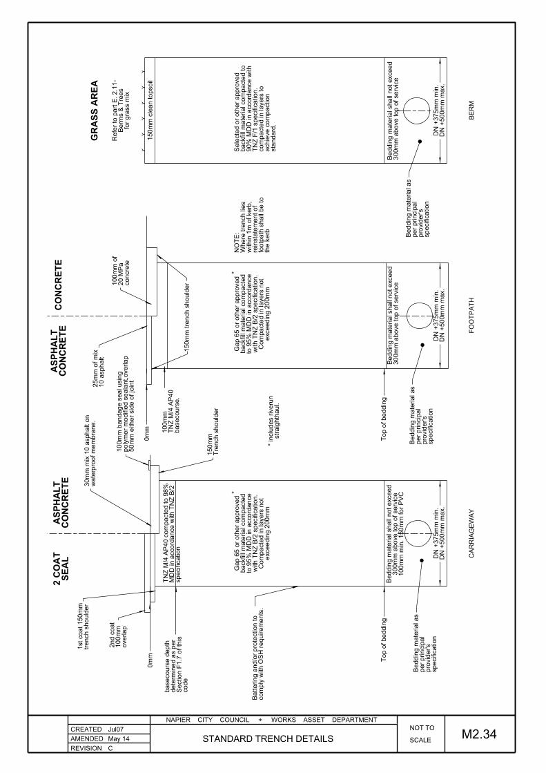
REVISION
NAPIER CITY COUNCIL + WORKS ASSET DEPARTMENT
CREATED
AMENDED SCALE
NOT TOJul07
STANDARD TRENCH DETAILS
exceedin
g 2
00
mm
Co
mpacte
d in layers n
ot
with T
NZ B/2 s
pecification.
to 9
5% M
DD in a
ccord
ance
backfill m
aterial co
mpacte
dGap 6
5 or oth
er appro
ved
exceedin
g 2
00
mm
Co
mpacte
d in layers n
ot
with T
NZ B/2 s
pecification.
to 9
5% M
DD in a
ccord
ance
backfill m
aterial co
mpacte
dGap 6
5 or oth
er appro
ved
300
mm a
bove top of service
Beddin
g m
aterial shall n
ot exceed
300
mm a
bove top of service
Beddin
g m
aterial shall n
ot exceed
sta
ndard.
achie
ve c
om
paction
co
mpacte
d in layers to
TN
Z F/1 s
pecification.
90
% M
DD in a
ccord
ance with
backfill m
aterial co
mpacte
d to
Selecte
d or oth
er appro
ved
CO
NC
RE
TE
GR
AS
S A
RE
A
150
mm clean topsoil
for grass mix
Berm
s & Tre
es
Refer to p
art E. 2.1
1-
straig
hth
aul.
* inclu
des riveru
n
**
M2.34
DN +
500
mm m
ax.
DN +
375
mm min.
DN +
500
mm m
ax.
DN +
375
mm min.
DN +
500
mm m
ax.
DN +
375
mm min.
100
mm min. 150
mm for P
VC
300
mm a
bove top of service
Beddin
g m
aterial shall n
ot exceed
0m
m
Tre
nch s
houlder
150
mm
10 asphalt
25
mm of
mix
concrete
20 M
Pa
100
mm of
0m
m
Top of beddin
gTop of beddin
g
150
mm tre
nch s
houlder
waterpro
of
me
mbra
ne.
30
mm mix 1
0 asphalt o
n
CO
NC
RE
TE
AS
PH
AL
T
CO
NC
RE
TE
AS
PH
AL
T
SE
AL
2 C
OA
T
May 14
C
code
Section F
1.7 of this
determined as p
er
basecours
e d
epth
specification
MD
D in a
ccord
ance with T
NZ B/2
TN
Z M/4 A
P40 c
om
pacte
d to 9
8%
the kerb
footp
ath s
hall b
e to
reinstate
ment of
within 1
m of kerb,
Where tre
nch lies
NO
TE:
50
mm either side of joint
poly
mer
modifie
d seala
nt,overlap
100
mm b
andage seal usin
g
trench s
houlder
1st coat 150
mm
overlap
100
mm
2nd c
oat
CA
RRIA
GE
WA
YF
OO
TP
AT
HB
ER
M
basecours
e.
TN
Z M/4 A
P40
100
mm
co
mply with O
SH require
ments.
Battering a
nd/or prote
ction to
specification
pro
vider's
per principal
Beddin
g m
aterial as
specification
pro
vider's
per principal
Beddin
g m
aterial as
specification
pro
vider's
per principal
Beddin
g m
aterial as

REVISION
NAPIER CITY COUNCIL + WORKS ASSET DEPARTMENT
CREATED
AMENDED
Nov 07
EDGE PROTECTION FOR DRAIN DEPTH <1.0mRURAL ROAD / ACCESSWAY ENTRANCE - M2.35
SCALE
NOT TO
Mar 14
B
Access
way
Rural R
oad or
Water table
'Z' CLASS PIPE END PROTECTION
75
75
Road Boundary
RCRRJ pipe300mm Dia min.
Edge of seal
200x150mm Concrete collar.
6:1 max.Cut face at 4:1 min.
to cover exposed reinforcing10mm epoxy cap over cut end
refer below for details.chamfered culvert end.
Rural Road
Invert of drain
Driveway surface
3. No concrete filled bags or similar are to be used.
150mm thick by 200mm wide concrete "collar" pipe
2. The exposed end of the pipe is to be encased in
1. Only concrete pipes are to be used. Minimum diameter 300mm
NOTES
Less than 1.0
m
Whole numbers = mm. Decimalised numbers = m.NOTE:

REVISION
NAPIER CITY COUNCIL + WORKS ASSET DEPARTMENT
CREATED
AMENDED
Nov 07
M2.36SCALE
NOT TO
Fill Batter
Fill Berm
*See Note 1
Subgrade
Pavement
Pave
ment
Depth
Varies
(See Note 3)
Cut B
atter
5:1 (S
ee Note
2)
Unsealed Metal Strip
FOR VERGES ON RURAL ROADS
TYPICAL CROSS SECTION GUIDELINES
NOTES:
(B) 150mm below the pavement/subgrade interface.
(A) 500mm below the seal edge, or
*Adopt which ever provides the greater depth:1.
within 3.0m of topside of curves. of 4:1 in constrained locations. 6:1 side slopes are required 5:1 Side slopes may be narrowed to an absolute minimum2.
in Table F1. given in 'Note 1' above, but with minimum width as shown The verge width is determined by the critical dimensions3.
See Drawing M2.1 for typical cross section details4.
Mar 14VERGES ON RURAL ROADS
CROSS SECTION GUIDELINES FOR
B
150
* min.
VergeBerm
100
Whole numbers = mm. Decimalised numbers = m.NOTE:
1.00 min 500 min
500 min

REVISION
NAPIER CITY COUNCIL + WORKS ASSET DEPARTMENT
CREATED
AMENDED SCALE
NOT TOJun 07
M2.37Mar 14
B
CYCLE FACILITY DESIGN GUIDE

REVISION
NAPIER CITY COUNCIL + WORKS ASSET DEPARTMENT
CREATED
AMENDED
Jul 01
SCALE
NOT TO
May 14
C
NOTE: Whole numbers = mm. Decimalised numbers = m.
M2.38
Tape to be Class 1 (AS1906.1)3.
"Design Guides".Hold bars are to comply with Austroads 2.
powder coated white.medium wall thickness Galv. tube then Hand rails to be made from 50mm Ø 1.
NOTES:
CYCLIST HOLDING RAIL AND BIKE STAND DETAILS
(see detail).Reflective Tape
concrete path100mm thick
surround.250Ø Concrete
(Stainless Steel)M10 Grub screw
White Tape.
White Tape.
Red Tape.
Class 1 (AS 1906.1).Reflective Tape to be
0.6 (minimum)1.5 (desirable)
R=250mm
100
275
100
(see detail).Reflective Tape
surround.250 Ø Concrete
ELEVATION
HOLDING RAIL
TAPE DETAILREFLECTIVE
BIKE STAND DETAIL
PLAN
500
350
foundationx 250 wide
Stainless Cycle standType B,
20 MPa concrete.
footpath.concrete100mm thick
800 minim
um
100
0.5
1.0
mounting the handrail.act as a sleeve for suitable diameter to Aluminium socket of

REVISION
NAPIER CITY COUNCIL + WORKS ASSET DEPARTMENT
CREATED
AMENDED
Jul 01
SCALE
NOT TO
May 14
C
NOTE: Whole numbers = mm. Decimalised numbers = m.
M2.38aCYCLIST DEFLECTION RAIL DETAIL
Tape to be Class 1 (AS1906.1)3.
"Design Guides".Hold bars are to comply with Austroads 2.
powder coated white.medium wall thickness Galv. tube then Rails to be made from 50mm Ø 1.
NOTES:
(see detail).Reflective Tape
concrete path100mm thick
(Stainless Steel)M10 Grub screw
White Tape.
White Tape.
Red Tape.
Class 1 (AS 1906.1).Reflective Tape to be
3.0
100
275
100
100
min
R=250mm
1.4
Deflection Rail 2m Radius
Tactile line marking
Edge of path
Edge of path
1:10 Taper 1:10 Taper
1:10 Taper 1:10 Taper
DEFLECTION RAIL
TAPE DETAILREFLECTIVE
PLAN OF DEFLECTION RAIL SETUP
mounting the handrail.act as a sleeve for suitable diameter to Aluminium socket of
surround.250mm Ø Concrete
100
500
1.0

REVISION
NAPIER CITY COUNCIL + WORKS ASSET DEPARTMENT
CREATED
AMENDED
Jun 09
M2.39SCALE
NOT TO
Boundary or fe
nce
Boundary or fe
nce
Mar 14
B
*
* 1.25m minium clearance to allow access by mobility scooters
Refer to Std Dwg M2.38 for Reflective tape details.NOTE:
MOTOR VEHICLE RAIL BARRIER
PLAN
ELEVATION
Varies
1.3
0
150
R
Varies
400300
powder coated white.galvanised steel pipe,50mm min dia
concrete path.100mm thick
to act as sleeve.Galvanised socket
(Stainless steel).M10 Grub screw
Whole numbers = mm. Decimalised numbers = m.NOTE:
1.0
0
800
800
300 min1500 max

REVISION
NAPIER CITY COUNCIL + WORKS ASSET DEPARTMENT
CREATED
AMENDED
Jun 09
AND CHANNELSTORMWATER CONNECTION TO KERB M2.40SCALE
NOT TO
Mar 14
B
FOR KERB AND CHANNEL REPLACEMENT ONLYSTORMWATER CONNECTION TO STANDARD KERB AND CHANNEL
FULL WIDTH BERMSTORMWATER CONNECTION TO STANDARD KERB AND CHANNEL
The invert of adaptor shall be level with invert of channel.NOTE:
Whole numbers = mm. Decimalised numbers = m.NOTE:
BOUNDARY
BOUNDARY
25
25
Varies
Pipe Adaptor.Existing
match the kerb profile and colour.2 part epoxy mortar toRebuild the kerb using
Sawcut.
kerb face profile.RHS angled to match
closely over RHS ends.joining band to fit
Stainless steel
to pipe adaptor.RHS connection from kerb100 x 75 x 3mm galvinised
match the kerb profile and colour.2 part epoxy mortar toRebuild the kerb using
kerb face profile.RHS angled to match
Sawcut.
located inside boundary.DN100mm uPVC pipe adaptor
inside pipe adaptorThis end of RHS to fit
closely over RHS ends.joining band to fit
Stainless steel
to pipe adaptor.RHS connection from kerb100 x 75 x 3mm galvinised
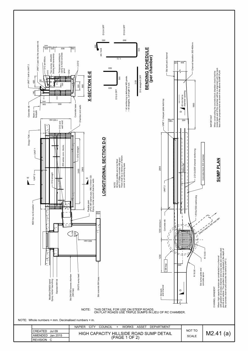
REVISION
NAPIER CITY COUNCIL + WORKS ASSET DEPARTMENT
CREATED
AMENDED
Jul 09
SCALE
NOT TO
M2.41 (a)C
(PAGE 1 OF 2)HIGH CAPACITY HILLSIDE ROAD SUMP DETAIL
Jan 2015
(per cha
mber)
cover to all reinforcin
g b
ars
There s
hall b
e a minim
um of 50
mm
with 1
7.5
Mpa c
oncrete infill gro
ut.
All block cavities are to b
e fille
d
NO
TE
Epoxy m
ortar aro
und c
ha
mber
walls
uP
VC M
H starter pipe,
RRJ 3
15
mm O
D
Fle
xible joint.
D12 straig
ht-5 O
FF
8-D
12-4
00
150
UNIT 2
40
mm fall
400
145
Concrete nib
Modifie
d D
N600 b
arrel
Epoxy m
ortar haunchin
g
600 mim
UNIT 2 cast into the c
oncrete nib
Concrete b
ase
450
std. hook
840
520
1-R
10x1500 reinforcin
g
DD
Cha
mber end w
alls
500
500
500
D12-2 O
FF
D12-8 O
FF
D12-8 O
FF
E E
CH
AN
NE
L G
RA
DIE
NT
min.
Silt trap
190
1200 minim
um
2900
2400
1800
350
300
2800
600200220
1204
20
150
min.
300 800
40
190
320
260
1105 min.
200 series c
onc. blocks
2.6
5
1.13
800
IMP
OR
TA
NT
1200
(Silt trap)
Std D
N1050 a
ccess c
ha
mber
Std c
oncrete M
H b
ase
D12-straig
ht
D12-straig
ht
UNIT 2
M20 h
ex n
ut
& w
asher
UNIT 1
Desig
n T
OK
Concrete nib
footp
ath
Berm or
UNIT 1 b
olt to U
NIT 2
D12 at 400crs.
2-D
12
All straig
hts, cut le
ngth to s
uit.
All reinforcin
g is d
eform
ed M
S gra
de.
wall reinf.
D12 e
nd
the c
oncrete c
hannel and c
oncrete nib b
ehin
d U
NIT 2.
plu
mb a
nd vertical. T
he gra
die
nt slo
pe is a
djuste
d in the d
epth of
with gra
die
nt all a
ccess c
ha
mber and s
um
p w
alls are c
onstructe
d
Where hig
h capacity s
um
ps are c
onstructe
d in a c
hannel
face of th
e pro
posed kerb as s
ho
wn in the a
bove S
UM
P P
LA
N
inside b
ack w
all of th
e c
ha
mber
will be in align
ment
with the b
ack
When c
onstructing the c
oncrete block c
ha
mber check that th
e
concrete a
pro
n
Std s
um
p grate a
nd
R 1
0.0
0
R 1
0.0
0C
oncrete block S
W c
ha
mber
2-D
12x3200 c
hannel reinforcin
g
cha
mber openin
g
40 m
m fall to
UNIT 1 c
hequer plate kerb top
Std kerb a
nd c
hannel
Channel transitio
n 3
00-4
00
mm
and c
hannel
Std kerb
main
To S
W
Sta
ndard M
H lid
DN
375 s
um
p lead
D12
DN37
5 lead to S
W main
MH
D12
D12
D12
2x
D12
gro
ut
cavity to h
old c
oncrete
Te
mporary p
ackin
g in
blocks laid tra
nsversly
Top c
ours
e, 400x200
LO
NGIT
UDIN
AL S
EC
TIO
N D-D
X-S
EC
TIO
N E-E
BE
NDIN
G S
CH
ED
UL
E
SU
MP P
LA
N
ON FLAT ROADS USE TRIPLE SUMPS IN LIEU OF RC CHAMBER.THIS DETAIL FOR USE ON STEEP ROADS.NOTE:
Whole numbers = mm. Decimalised numbers = m.NOTE:

REVISION
NAPIER CITY COUNCIL + WORKS ASSET DEPARTMENT
CREATED
AMENDED SCALE
NOT TOJul 09
M2.41 (b)Jan 14
C(PAGE 2 OF 2)
HIGH CAPACITY HILLSIDE ROAD SUMP DETAIL
NTS
NTS
100
5
R
25
165
400
500 T
ypical
6m
m M
S plate
35
135
90
B B
A
A
C C
6 (
Typical)
2400 O/A
112 o
verall
Stiffener 10
mm M
S
125
185
500
500 T
ypical
200
500
500 T
ypical
100 180
30
165
105
500 T
ypical
440
280
2802370 O/A
125
End plates 6
mm M
S
after
manufa
cture
Hot dip g
alvanise b
oth u
nits
NO
TE
to form kerb top
5m
m c
hequer plate, folded
Gusset
End plate 6
mm M
S
100x10 M
S flat
Stiffeners
6m
m M
S plate
Drill 5 h
oles at 22 dia
100x10 M
S plate
End plates
Cha
mfer
End plate 1
0m
m M
S
R10 b
ars as s
ho
wn
Weld 5 e
qui-dista
nt
Anchor ro
ds.
Tack w
eld in place
M20x30 h
ex b
olt
Drill 5 h
oles at 22 dia
Gussets 5
mm M
S plate
End plate 1
0m
m M
S
UNIT 1 - F
RO
NT E
LE
VA
TIO
NX-S
EC
TIO
N A-A
X-S
EC
TIO
N B-B
X-S
EC
TIO
N C-C
UNIT 2 - F
RO
NT E
LE
VA
TIO
N
Whole numbers = mm. Decimalised numbers = m.NOTE:

A
A
1.20
2.40
TO GRATE40mm FALL
TO GRATE40mm FALL
40mm FALL40mm FALL
(SEE DETAIL)2 PART REMOVABLE CHECKER PLATE KERB
FOOTPATHROAD LEVEL
100
75
300
min
100
100
150
DN 375 SUMP LEAD
DN 375 SUMP LEAD
2 - D12 REINFORCING
AND SURROUNDSTANDARD SUMP GRATE
DN 375 uPVC SUMP - SUMP CONNECTIONS
KERB AND CHANNELBREAK LINE IN
R 1.0
R 1.0
DN 600 SUMP CHAMBER
PLATE KERB, (SEE DETAIL)2 PART REMOVABLE CHECKER
SUMP - SUMP CONNECTIONDN 375 uPVC
AND SURROUNDSTANDARD SUMP GRATE
2 - D12 REINFORCING
AT 300 CENTRESM20 HEX NUT AND WASHERUNIT 1 BOLT TO UNIT 2
DN 600 SUMP CHAMBER (X3)
SECTION A - A
REVISION
NAPIER CITY COUNCIL + WORKS ASSET DEPARTMENT
CREATED
SCALE
NOT TO
HIGH CAPACITY ROAD SUMP FOR FLAT AREAS M2.41 (c)Feb 12
C
AMENDED JAN 2015
Whole numbers = mm. Decimalised numbers = m.NOTE:

REVISION
NAPIER CITY COUNCIL + WORKS ASSET DEPARTMENT
CREATED
AMENDED
Jan 10
M2.42 (a)SCALE
NOT TO
May 14
C
TYPICAL PLAN OF PAVED THRESHOLD
PAVED THRESHOLD DETAILS
PAVED THRESHOLD
TYPICAL CROSS SECTION OF
1.00
1.00
Raised Platform
3.0
0
1.20
1.20
Proposed top of kerb.
flush with the top of kerb.Raised platform to be
be flush with the lip of channel.Concrete extension of ramp to
Existing top of kerb.
Proposed lip of channel.
range of pavers, 230 x 114 x 65mm.Colour "Rustic Red", ProfileHorizon International, Auckland.Nubrik clay pavers, from
Whole numbers = mm. Decimalised numbers = m.NOTE:
of soldier course.traffic dirction with bordera herring bone pattern 45° to230 x 114 x 65mm to be laid inProposed clay pavers
Design pavement. Design pavement.150
1.001.203.001.201.00
350high rounding30mm
100
asphaltic concrete.25mm min. thick
asphaltic concrete.25mm min. thick
40mm min. cover.655 mesh
bedding sand.30mm min. thick
30mm thick min. bedding sand.
range of pavers, 230 x 114 x 65mm.Colour "rustic Red", ProfileHorizon International, Auckland.Nubrik clay pavers, from
leveling course.75mm Thick AP20
basecourse.150mm min. AP40150mm min. thick Concrete.

REVISION
NAPIER CITY COUNCIL + WORKS ASSET DEPARTMENT
CREATED
AMENDED
Feb 10
SCALE
NOT TO
M2.42 (b)May 14
C
OF P
AV
ED R
AIS
ED P
LA
TF
OR
M
TY
PIC
AL C
RO
SS S
EC
TIO
N
PAVED RAISED PLATFORM
DE
TAIL A
A
M2.4
2b
1.0
01.2
01.0
05.0
01.0
01.2
01.0
0
150
100
65
mm P
avin
g blocks.
Whole numbers = mm. Decimalised numbers = m.NOTE:
150
35
mm thic
k b
eddin
g sand
65
mm P
avin
g blocks.
35
mm thic
k b
eddin
g sand
100
150
40
mm c
over
min.
665 M
esh
basecours
e 1
50
mm thic
kM
4 A
P40 c
om
pacte
d
20
MPa C
oncrete
M4 A
P40 c
om
pacte
d b
asecours
e

REVISION
NAPIER CITY COUNCIL + WORKS ASSET DEPARTMENT
CREATED
AMENDED
Jul 09
PEDESTRIAN AND SPLITTER ISLAND M2.43
TRAFFIC ISLAND KERB DETAIL
PEDESTRIAN ISLAND WITH 1.5m CROSSING
AS SHOWNMar 14
B
60°
1.50
50
5.0
0
R
400
R
65.0
0R
where specified.Tactile paving layout
SCALE 1:100
200
200
100
100
NIB
590mm long.
Existing Seal.
1.8
0 min.
SCALE NTS
300
R300R
9.00 min.
RG17
RG17
white paint.100mm wide reflectorised
Std Dwg M2.17.Hold rail to
Existing seal.
25mm Mortar bed.
30mm mix to AC.
(Refer to Std Dwg M2.19)Standard nib.
(Refer to Std Dwg M2.19)Standard precast kerb block.
crack sealed.from channel lip, joint to be Sawcut carriageway 600mm
60mm Thick pavers.
Precast kerb block
10mm min. mortar
Kerb painted reflectorised white.
20mm sand.
Compacted metal.
Sub-base.
100mm concrete infill.
100mm concrete infill.
Whole numbers = mm. Decimalised numbers = m.NOTE:
BLOCK ISLAND (PAVER INFILL)PART SECTION THROUGH KERBKERB BLOCK

REVISION
NAPIER CITY COUNCIL + WORKS ASSET DEPARTMENT
CREATED
AMENDED
Jan 10
M2.44SCALE
NOT TO
2 COAT SEAL LAPPING DETAIL
PAVEMENT JOINT DETAILS
JOINING DETAIL
ASPHALTIC CONCRETE
JOINING DETAIL
CHIPSEAL
C
150 min
at sawcut edgescoat 100mm min Overlap 2nd seal
June 15
2 Coat chip seal
Whole numbers = mm. Decimalised numbers = m.NOTE:
2) Pavement joint construction shall meet the National Code of Practice for utility operators access to transport corridors.
1) All sawcut joints in asphalt pavement must be sealed with approved hot poured rubber bitumen in accordance with NZTA, TNZ C/6
NOTES:
50 min 100 min
(Not to be undercut at edge).Existing Seal
side of jointbitumen band, 50mm either100mm hot poured rubber
Asphaltic concrete 25mm min
(not to be undercut at edge)Existing seal
sawcutFinal
chip seal onlyOverlap 2nd coat
basecourseNew AP40
100 min
Initial sawcut.
basecourseNew AP40
basecourseNew AP40
Initial sawcut
Initial sawcut
undercut at edges)(not to be Existing seal
basecourseUndisturbed
basecourseUndisturbed
basecourseUndisturbed

REVISION
NAPIER CITY COUNCIL + WORKS ASSET DEPARTMENT
CREATED
AMENDED
Jan 10
M2.45
END ELEVATIONELEVATION
ISOMETRIC
SCALE
NOT TO
FOR STANDARD KERB
PRECAST SUMP BLOCKMar 14
B
PLAN
60 35
220760220
45
35
60
78
158
180
184
130
250
25R
25
R 125
NOTE: All concrete to be 20MPa
10mm Chamfer.
Shear key formed by 50 x 50mm
338m Mesh.
centrally placed.D16 1200mm long,
Whole numbers = mm. Decimalised numbers = m.NOTE:

REVISION
NAPIER CITY COUNCIL + WORKS ASSET DEPARTMENT
CREATED
AMENDED M2.461:10
SCALE
May 14
C
Mar 10
PRECAST SUMP BLOCK FOR MOUNTABLE KERB
PLAN
END ELEVATION
NOTE: All concrete to be 20MPa
95
140
110
110
220
60
25
210
16
990
80
20
120
110770110
16mmØ Reo Bar
16mmØ Reo Bar & Curved Back to reduce chipping.Revised Front Edge
& Curved Back.Revised Front Edge
Whole numbers = mm. Decimalised numbers = m.NOTE:

REVISION
NAPIER CITY COUNCIL + WORKS ASSET DEPARTMENT
CREATED
AMENDED
Jan 10
M2.47SCALE
NOT TO
TREE PLANTER AND ROOT DIRECTOR DETAILMay 14
C
Whole numbers = mm. Decimalised numbers = m.NOTE:
850
650
1.10
Tree grates.UG - 1050
25mm asphaltic concrete.
Tree surrounds.
RD - 1050Root director
of root director.assist positioningSand layer to
Topsoil.
AP40 Basecourse.

REVISION
NAPIER CITY COUNCIL + WORKS ASSET DEPARTMENT
CREATED
AMENDED
Jan 10
M2.48SCALE
NOT TO
PROHIBITED LOCATIONS OF DRIVEWAYSMay 14
C
Whole numbers = mm. Decimalised numbers = m.NOTE:
Kerb
Kerb
Boundary
Boundary
Boundary
Kerb
Kerb
15.00 15.00
7.0
0
No vehicle crossingspermitted local roads.
15.0
0
No vehicle crossings permittedcollector, principal and arterial roads.
Boundary
No vehicle crossings permitted for multi unit development with 2 or more dwellings, for local roads.
No vehicle crossings permitted for multi unit development with 2 or more dwellings, for collector, principal andarterial roads.
REFER TO SECTION F1.6.14.2 LOCATION OF URBAN VEHICLE CROSSINGS
7.00 7.00

REVISION
NAPIER CITY COUNCIL + WORKS ASSET DEPARTMENT
CREATED
AMENDED
Jan 10
M2.49SCALE
NOT TO
PAVED THRESHOLD PAVER LAYOUTMay 14
C
Whole numbers = mm. Decimalised numbers = m.NOTE:
DETAIL B
DETAIL A
Road
STREET THRESHOLDS, RESIDENTIAL
BLOCK PATTERNS AND LAYING METHODS FOR
rampConcrete
NOTES:
Kerb and Channel.formed as part of the Concrete wedge to be
The herringbone pattern shall be laid at 45° to the traffic flow.4.
non-parallel discrepancies (Detail B).
Pavers abutting the concrete ramp shall be cut so as to accommodate minor
A soldier course is required around the total perimeter of the paved area.3.
the herringbone pattern is to be adjusted to suit.
maximum dimensions in two perpendicular directions not less than 50mm
In order to achieve more than half a paver or no part paver having 2.
of the Kerb and Channel.
Concrete wedge (Detail A) shall be formed as part1.
pavers to be cut.Soldier course
Soldier course.
Reinforced nib.
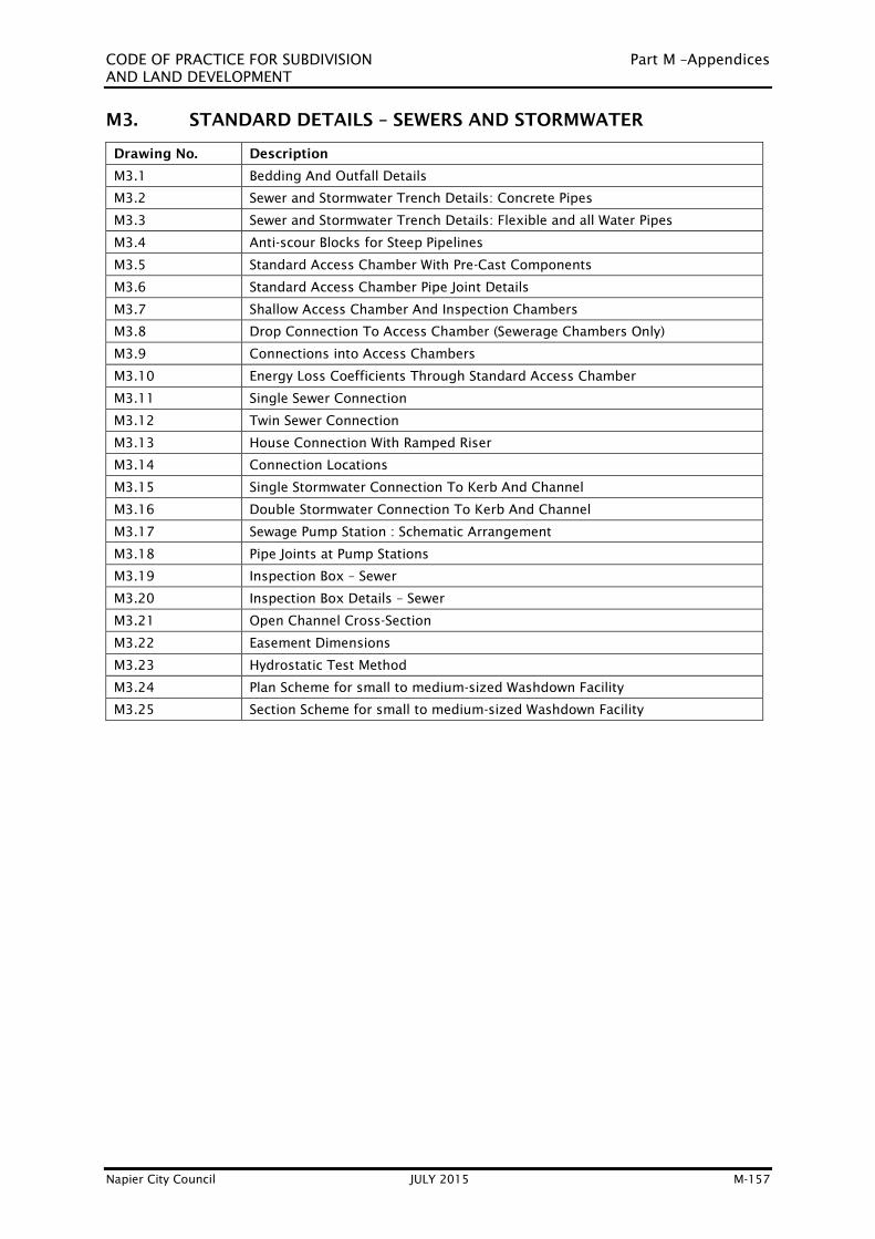
CODE OF PRACTICE FOR SUBDIVISION Part M –Appendices
AND LAND DEVELOPMENT
Napier City Council JULY 2015 M-157
M3. STANDARD DETAILS – SEWERS AND STORMWATER
Drawing No. Description
M3.1 Bedding And Outfall Details
M3.2 Sewer and Stormwater Trench Details: Concrete Pipes
M3.3 Sewer and Stormwater Trench Details: Flexible and all Water Pipes
M3.4 Anti-scour Blocks for Steep Pipelines
M3.5 Standard Access Chamber With Pre-Cast Components
M3.6 Standard Access Chamber Pipe Joint Details
M3.7 Shallow Access Chamber And Inspection Chambers
M3.8 Drop Connection To Access Chamber (Sewerage Chambers Only)
M3.9 Connections into Access Chambers
M3.10 Energy Loss Coefficients Through Standard Access Chamber
M3.11 Single Sewer Connection
M3.12 Twin Sewer Connection
M3.13 House Connection With Ramped Riser
M3.14 Connection Locations
M3.15 Single Stormwater Connection To Kerb And Channel
M3.16 Double Stormwater Connection To Kerb And Channel
M3.17 Sewage Pump Station : Schematic Arrangement
M3.18 Pipe Joints at Pump Stations
M3.19 Inspection Box – Sewer
M3.20 Inspection Box Details – Sewer
M3.21 Open Channel Cross-Section
M3.22 Easement Dimensions
M3.23 Hydrostatic Test Method
M3.24 Plan Scheme for small to medium-sized Washdown Facility
M3.25 Section Scheme for small to medium-sized Washdown Facility

CODE OF PRACTICE FOR SUBDIVISION Part M –Appendices
AND LAND DEVELOPMENT
Napier City Council JULY 2015 M-158
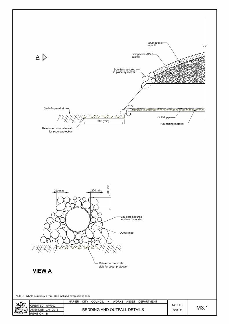
Bed of open drain
slab for scour protection
Reinforced concrete
200 min.
200 min.
200 min.
for scour protection
Reinforced concrete slab
900 (min)
A
in place by mortarBoulders secured
Outfall pipe
backfillCompacted AP40
topsoil200mm thick
Outfall pipe
Haunching material
in place by mortarBoulders secured
VIEW A
APR 02
REVISION
NAPIER CITY COUNCIL + WORKS ASSET DEPARTMENT
CREATED
AMENDED
Whole numbers = mm. Decimalised expressions = m.NOTE:
SCALE
NOT TO
BEDDING AND OUTFALL DETAILSJAN 2015
B
M3.1
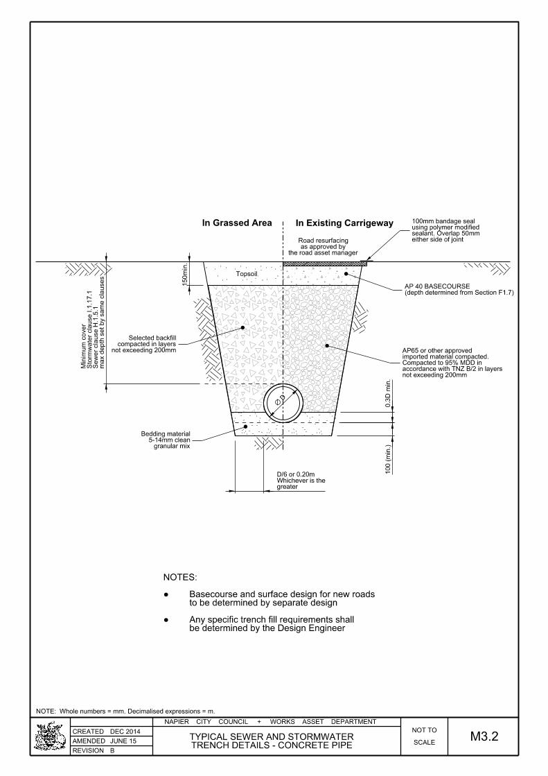
In Grassed Area In Existing Carrigeway
the road asset manageras approved by
Road resurfacing
Topsoil
max d
epth set by sa
me cla
uses
Se
wer cla
use H.1.5.1
Storm
water cla
use I.1.1
7.1
Minim
um c
over
either side of jointsealant. Overlap 50mm using polymer modified100mm bandage seal
greaterWhichever is theD/6 or 0.20m
D
granular mix5-14mm clean
Bedding material
(depth determined from Section F1.7)AP 40 BASECOURSE
not exceeding 200mmaccordance with TNZ B/2 in layers Compacted to 95% MDD in imported material compacted.AP65 or other approved
0.3
D min.
100 (
min.)
150
min.
not exceeding 200mm compacted in layers
Selected backfill
be determined by the Design EngineerAny specific trench fill requirements shall●
to be determined by separate designBasecourse and surface design for new roads ●
NOTES:
REVISION
NAPIER CITY COUNCIL + WORKS ASSET DEPARTMENT
CREATED
AMENDED
Whole numbers = mm. Decimalised expressions = m.NOTE:
DEC 2014
SCALE
NOT TO
M3.2JUNE 15
BTRENCH DETAILS - CONCRETE PIPETYPICAL SEWER AND STORMWATER

In Grassed Area In Existing Carrigeway
150
min
C
B
Minimum Dimensions
>450, <=900
>300, <=450
>150, <=300
>=75, <=150
150
100
100
75
b c o B=D+2C
1050-1500
700-850
450-600
275-350
bo
300
200
150
100
150
150
150
100
Ø (Diameter)
the road asset manageras approved by
Road resurfacing
D
max d
epth set by sa
me cla
uses
Se
wer cla
use H.1.5.1
Storm
water cla
use I.1.1
7.1
Minim
um c
over
either side of jointsealant. Overlap 50mm using polymer modified100mm bandage seal
Topsoil
5-14mm clean rounded granular mixBedding and surround material
TNZ M4 AP40(depth determined from Section F1.7)BASECOURSE
not exceeding 200mmaccordance with TNZ B/2 in layers Compacted to 95% MDD in imported material compacted.AP65 or other approved
not exceeding 200mmcompacted into layers
Selected backfill
be determined by the Design EngineerAny specific trench fill requirements shall●
NOTE:
REVISION
NAPIER CITY COUNCIL + WORKS ASSET DEPARTMENT
CREATED
AMENDED
Whole numbers = mm. Decimalised expressions = m.NOTE:
DEC 2014
M3.3SCALE
NOT TO
B
JUNE 2015TRENCH DETAILS - FLEXIBLE PIPES
TYPICAL SEWER AND STORMWATER

G.L.
D/2
Ground lev
el
Pipeline
150
150150
Trench side
150
300
minimum cover to pipeDotted line indicates
before pouring concrete to pipe wall6mm Denso Tape or similar
If pipe is uPVC, then wrap with
duct cast through block30mm uPVC drainage
300
duct cast through block30mm uPVC drainage
of not less than 17 MPamaterial to give a strength Cement stabilised bedding
20MPaConcrete
LONGITUDINAL SECTION
CROSS SECTION
MAR 07
REVISION
NAPIER CITY COUNCIL + WORKS ASSET DEPARTMENT
CREATED
AMENDED ANTI-SCOUR BLOCKS FOR STEEP PIPELINES SCALE
NOT TO
Whole numbers = mm. Decimalised expressions = m.NOTE:
JAN 2015
B
M3.4
unless directed otherwise by the NCC Asset Manager.
Anti-scour blocks to be place behind every second pipe joint,
NOTE:

APR 02
REVISION
NAPIER CITY COUNCIL + WORKS ASSET DEPARTMENT
CREATED
AMENDEDPRE-CAST COMPONENTS
STANDARD ACCESS CHAMBER WITHSCALE
NOT TO
Whole numbers = mm. Decimalised expressions = m.NOTE:
JAN 2015
B
M3.5
150 min
match pipe heightInner shape toup to DN1050Pipe >=DN600
size Manhole riserStandard DN1050 minimum
Bedding material.
typical trenchBackfill - as per
Concrete20MPa
FROM DN600 TO DN1050 PIPES
150
150
990mm opening
Bedding material.
Concrete.20 MPa
Pipe >=DN1050
Manhole riser Standard DN1050 (mininum)
REINFORCED CONCRETE PIPES
MANHOLES FOR >=DN1050
1 in 4
100
600mm min.
400
mm m
ax.
or approved epoxy mortar.20MPa concrete mortar
rungs @ 300mm crs.coated stainless steel 316 ladderthan 1.4m fix approved plasticFor access chambers deeper
riser sections.Standard DN1050
fixed with epoxy mortar.Approved frame and lid
CLEAR OPENING
Thro
at
thic
kness
NOTE:
Covers and frames shall comply with
AS3996 Class D, and have a clear
opening of not less than 600mm.
Covers shall be hinged for all
manholes.
When used in roads,hinge should be
located on the side nearest to
oncoming traffic.
other approved method.fixed using 3 x masonary bolts or
rings (maximum thickness 100mm each)Concrete spacing/ adjustment
Ordinary grade 20MPa haunching.
Standard precast base.
100mm thick compacted base.
HN-HO-72Standard precast lid designed to
STANDARD ACCESS CHAMBER
PRECAST OR INSITU

APR 02
REVISION
NAPIER CITY COUNCIL + WORKS ASSET DEPARTMENT
CREATED
AMENDEDJOINT DETAILS
STANDARD ACCESS CHAMBERSCALE
NOT TO
Whole numbers = mm. Decimalised expressions = m.NOTE:
JAN 2015
B
M3.6
(Sewer).Earthenware half pipe
(Sewer).Earthenware half pipe
min.
15
mm g
ap
50
100500 500100
75
150 75
500
100 100
150
50
(stormwater).Plaster finish to concrete
100
25
barrel DN 1050Precast access chamber
Pipe stub.
Plaster
(stormwater).Plaster finish to concrete
epoxy mortar.50mm throat
barrel DN 1050.Precast access chamber
epoxy mortar.50mm throat
Plaster.
on exterior of PVC pipe.Solvent glue & sand
PVC. PIPE DETAIL
CONCRETE PIPE DETAIL

REVISION
NAPIER CITY COUNCIL + WORKS ASSET DEPARTMENT
CREATED
AMENDED
APR 02
Whole numbers = mm. Decimalised expressions = m.NOTE:
M3.7AND INSPECTION CHAMBERS
SHALLOW ACCESS CHAMBERSSCALE
NOT TO
JAN 2015
B
TYPICAL SECTION
ORIENTATION OF BRANCH ENTRIES (TYPICAL)
INSPECTION CHAMBER AND SHALLOW ACCESS CHAMBER
Up to 225Ø
approved manhole cover and frameStandard Napier City Council
barrel DN600 minimumPrecast access chamber
HaunchingConcrete
designed to HW-HO-72Precast concrete lid
Surround20MPa Concrete
300-500 300-500
500 max 500 max
Maximum pipe size connected DN225Depth not exceed 900mmNOTES:
length cut to suit.DN 600 sump barrel
max.45°00'00"
metal baseCompacted

APR 02
REVISION
NAPIER CITY COUNCIL + WORKS ASSET DEPARTMENT
CREATED
AMENDED M3.8
Whole numbers = mm. Decimalised expressions = m.NOTE:
SCALE
NOT TO
C
MAY 2015(SEWERAGE CHAMBERS ONLY)
DROP CONNECTION TO ACCESS CHAMBER
CompactedMixedMetal
Compacted MixedMetal
1 in
4
100 min.
FGL
frame to concreteEpoxy mortar
Epoxy mortar around pipe
and maintenance.Tee for inspection
via smooth bendchannel entry
to be continuous intoDrop connection
500mm
50mm (max.)
Flexible Joint
Fill Void with Epoxy Mortar
Standard DN1050 Manhole Riser and anchor as requiredapproved plastic pipe clipGrade 316 stainless steel or
haunchingGrade 20MPa concrete
Normal bedding
SECTION THRU CHAMBER
Flow
Flow
Flow
Sewer main
via smooth bendchannel entry
to be continuous intoDrop connection
PLAN OF MANHOLE

MAR 10
APR 10
REVISION
NAPIER CITY COUNCIL + WORKS ASSET DEPARTMENT
CREATED
AMENDED
A
SCALE
NOT TO
Whole numbers = mm. Decimalised expressions = m.NOTE:
CONNECTIONS INTO ACCESS CHAMBERS M3.9
)elbiss
op erehw( decaps yllauqe
snoitcennoc 6 mumixaM
45° 45°
1
2
3 4
5
6
Precast Chamber
1050mm I.D.
No connections
FL
OW

APR 10
APR 02
REVISION
NAPIER CITY COUNCIL + WORKS ASSET DEPARTMENT
CREATED
AMENDED
ATHROUGH STANDARD ACCESS CHAMBER
ENERGY LOSS CO-EFFICIENTSSCALE
NOT TO
Whole numbers = mm. Decimalised expressions = m.NOTE:
M3.10
DN PIPE (mm)
CHANGE OF DIRECTION (degrees)
7 10 15 20 25 30 35 40 45 50 60 70 80 90
0.0
0.02
0.04
0.06
0.08
0.10
0.12
0.14
0.16
0.18
0.20
0.22
0.24
0.26
0.28
900
825
750
675
600
525
450
375
300
225
CHAMBER
DN 1050 ACCESS
DIRECTION IN
FOR CHANGE OF
LOSS COEFFICIENT K

AUG 07
REVISION
NAPIER CITY COUNCIL + WORKS ASSET DEPARTMENT
CREATED
AMENDED CONNECTIONSEWER SINGLE
Whole numbers = mm. Decimalised expressions = m.NOTE:
JUNE 15
C
M3.11SCALE
NOT TO
Ground Level
X X
BendDN 100 x 45°
Sewer MainDN 225 or DN 150
12001200
DN100 riser connection
45° DN100 Junction
DN100 PVC Sewer Pipe
BendDN100 x 45°
100Ø Lateral
DN225 PVC Sewer Pipe
500
1350 min
1350 min.
up to the boundary
same lateral, the lateral is to be DN150
NOTE: Where 2 properties connect into the
SP-SO 45°225 x 100 Junction
Boundary
Boundary
footp
ath
Boundary
min. 500
min. 300
400
Sealing cap
Capped end
PLAN
SECTION X - X

AUG 07
REVISION
NAPIER CITY COUNCIL + WORKS ASSET DEPARTMENT
CREATED
AMENDED CONNECTIONSEWER TWIN
Whole numbers = mm. Decimalised expressions = m.NOTE:
JUNE 15 M3.12SCALE
NOT TO
B
X X
chamberMarley civil inspection2.
OR
tested to 5m,riser connection pressureFibreglass (FRP) 100mm1.
Either
2700
1200 1200
SP-SO 45°150 x 100 Junction
Ground Level
DN100 riser connection
Inspection eye
Sewer MainDN 225 or DN 150
Junction SP-SO 45°225 x 150 or 150 x 150
BendDN 150 x 45°
Sealed inspection / rodding eye.
DN225 PVC Sewer Pipe
BendDN100 x 45°
SP-SO 90°150 x 100 Junction
DN100 PVC Sewer Pipe
45° DN100 Junction
DN100 riser connection
SP-SO 45°150 x 100 Junction
Reducer150 x 100
Boundary
footp
ath
Kerb
Boundary
min. 500
min. 300
400
0.5 to 1m
0.5 to 1m
Boundary
Cap end of pipe
Cap end of pipe
PLAN
SECTION X - X

APR 02
REVISION
NAPIER CITY COUNCIL + WORKS ASSET DEPARTMENT
CREATED
AMENDED SCALE
NOT TO
Whole numbers = mm. Decimalised expressions = m.NOTE:
JAN 2015
BWITH RAMPED RISER
HOUSE CONNECTION M3.13
Boundary
500 min.
700 to 1.6
0
100
cap. Sealed
or preformed y for new construction.Factory saddle for connection to existing
gradePipe laid at minimum

APR 02
REVISION
NAPIER CITY COUNCIL + WORKS ASSET DEPARTMENT
CREATED
AMENDED M3.14SCALE
NOT TO
CONNECTION LOCATIONS
Whole numbers = mm. Decimalised expressions = m.NOTE:
JUNE 15
B
L
LimitLimit
FlowFlow
Boundary
Boundary
the limits above.
Connections preferably located in front of a property and within
NOTE:
45°45°
C Service
0.5 to 1m0.5 to 1m
Access ChamberAccess Chamber
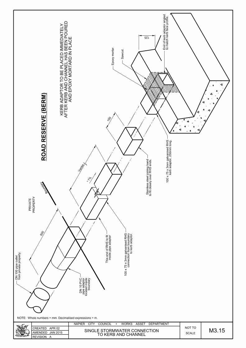
APR 02
REVISION
NAPIER CITY COUNCIL + WORKS ASSET DEPARTMENT
CREATED
AMENDED
A
Whole numbers = mm. Decimalised expressions = m.NOTE:
M3.15SCALE
NOT TO
TO KERB AND CHANNELSINGLE STORMWATER CONNECTION
JAN 2015
AN
D E
PO
XY M
OR
TA
RD I
N P
LA
CE
AF
TE
R K
ER
B A
ND C
HA
NN
EL H
AS B
EE
N P
OU
RE
D
KE
RB A
DA
PT
OR T
O B
E P
LA
CE
D I
MM
EDIA
TE
LY
1%
Boundary
*
Varies
PR
OP
ER
TY
PRIV
AT
E
500
150
125
Epoxy m
ortar.
Sa
wcut.
fro
m private pro
perty.
DN 1
00 pipe o
utlet
boundary
locate
d inside
pipe a
daptor
DN 1
0 P
VC
inside pipe a
daptor
This e
nd of
RH
S to fit
to kerb a
daptor.
connection fro
m b
oundary
100 x 7
5 x 3
mm g
alvanised R
HS
to fit closely o
ver
RH
S e
nds.
Stainless ste
el joinin
g b
and
kerb a
daptor, 2
50
mm long.
100 x 7
5 x 3
mm g
alvanised R
HS
to m
atc
h kerb face profile.
End of kerb a
daptor angle
d
RO
AD R
ES
ER
VE (
BE
RM)
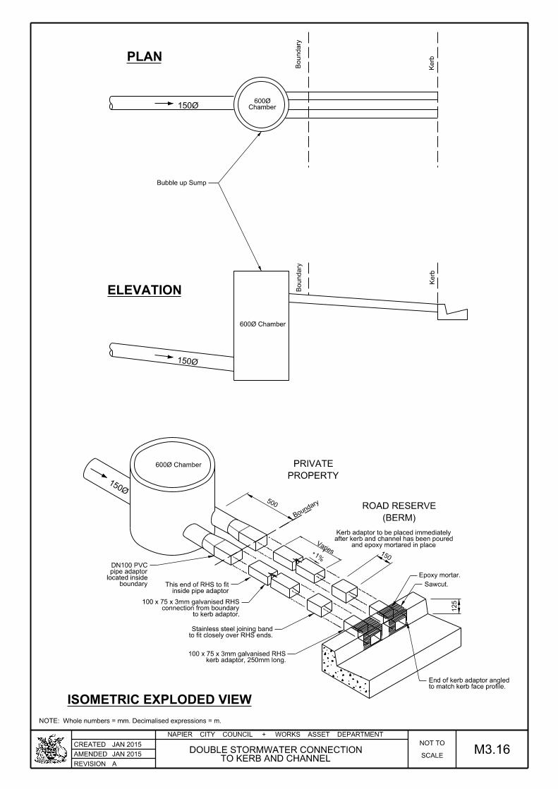
REVISION
NAPIER CITY COUNCIL + WORKS ASSET DEPARTMENT
CREATED
AMENDED
A
Whole numbers = mm. Decimalised expressions = m.NOTE:
SCALE
NOT TO
TO KERB AND CHANNELDOUBLE STORMWATER CONNECTION
JAN 2015
JAN 2015
M3.16
1%*
500
150
150Ø
600Ø Chamber
150Ø
600Ø Chamber
150Ø
Boundary
Boundary
Kerb
Kerb
PROPERTY
PRIVATE
(BERM)
ROAD RESERVE
Chamber600Ø
and epoxy mortared in placeafter kerb and channel has been poured Kerb adaptor to be placed immediately
Varies
Boun
dary
125
Epoxy mortar.
Sawcut.boundarylocated insidepipe adaptorDN100 PVC
inside pipe adaptorThis end of RHS to fit
to kerb adaptor.connection from boundary
100 x 75 x 3mm galvanised RHS
to fit closely over RHS ends.Stainless steel joining band
kerb adaptor, 250mm long.100 x 75 x 3mm galvanised RHS
to match kerb face profile.End of kerb adaptor angled
Bubble up Sump
PLAN
ISOMETRIC EXPLODED VIEW
ELEVATION

APR 02
REVISION
NAPIER CITY COUNCIL + WORKS ASSET DEPARTMENT
CREATED
AMENDED SCALE
NOT TO
SCHEMATIC ARRANGEMENTSEWERAGE PUMP STATION:
Whole numbers = mm. Decimalised expressions = m.NOTE:
JAN 2015
B
M3.17
PUMP STATION
Influent
Influent
connection.Scour and or emergency
Station valve.
to allow complete isolation.clear of pump stationIsolation valves
emergency pump.
sump for temporarysuitable as pumpIsolation manhole
Reflux valve.Isolating valve.

REVISION
NAPIER CITY COUNCIL + WORKS ASSET DEPARTMENT
CREATED
AMENDED
APR 02
SCALE
NOT TO
PIPE JOINTS AT PUMP STATIONS
Whole numbers = mm. Decimalised expressions = m.NOTE:
JAN 2015
B
M3.18
STATIONPUMP
200 min.
Pump station wall
Puddle flange
Flexible joint
Inlet or outlet pipe.
500min.
submitted for approvalMaterial type to beRigid Pipe:
500

REVISION
NAPIER CITY COUNCIL + WORKS ASSET DEPARTMENT
CREATED
AMENDED
JUL 07
Whole numbers = mm. Decimalised expressions = m.NOTE:
SCALE
NOT TO
M3.19SEWER
INSPECTION BOXJAN 2015
B
215
5
5 5
5
35
395
55
300
35
3. All plan dimensions nominal
2. Letters and pattern to be raised 3mm
but shall be metal in carriageways
high density polyethylene (black) in berms
1. Inspection and valve box material shall be
NOTES:
250 nom.
250
345 nom. 2525
75
SECTION A - A
PLAN

REVISION
NAPIER CITY COUNCIL + WORKS ASSET DEPARTMENT
CREATED
AMENDED
A
JUL 07
Whole numbers = mm. Decimalised expressions = m.NOTE:
M3.20SEWER
INSPECTION BOX DETAILSJAN 2015 SCALE
NOT TO
250
36
35
SECTION A - A LID
215
Plan dimensions nominal3.
to under side of lid (black)
galvanised bar to be attached
2. 100mm long x 5mm diameter
high density polyethelyene
Inspection box material shall be1.
NOTES:
SECTION B - B LID
215 nom. 5
250
5
250 nom.25 25
35
5
75
5
45
180
SECTION B - B
250 nom.
215 n
om.
5
5
5
35
PLAN UNDERSIDE OF LID

APR 02
REVISION
NAPIER CITY COUNCIL + WORKS ASSET DEPARTMENT
CREATED
AMENDED SCALE
NOT TO
Whole numbers = mm. Decimalised expressions = m.NOTE:
OPEN CHANNEL CROSS-SECTIONJAN 2015
B
lateral spread during seismic events.
geotechnic recommendations, to mitigte the effects of
Note: In certain situations profiles may be amended in line with
M3.21
widthDesign
MINIMUM BERM REQUIREMENTS
The minimum width shall be 6.0 metres.with gradients 1 in 5 or flatter.
Alternative with one or both sides
6.0
6.0
6.0
6.0
6.06.0
widthDesign
6.0min.
1 in 5 or flatter.

GL
NOV 07
REVISION
NAPIER CITY COUNCIL + WORKS ASSET DEPARTMENT
CREATED
AMENDED DIMENSIONSEASEMENT SCALE
NOT TO
Whole numbers = mm. Decimalised expressions = m.NOTE:
Case (a)
of 2.0m.
This gives an easement width of 1.95m which is almost the same as the Code requirement
pipe to the side of the foundation is a minimum of 975mm.
line from the side of a trench required to maintain the pipe, a distance from the centre of the
order of 900mm deep. Given those dimensions and the need for the foundation to meet the 45°
In essence the normal house foundation is 300mm deep and a Sewer connection will be in
JAN 2015
B
Stormwater) is less than 1.0m to invert.
to another may be reduced to 2.0m where the service (Water, Sewer or
Easements for privately owned service connections that pass from one allotment(b)
0.4m with the service laid in the center. The minimum width shall be 3.0m.
A width equal to twice the depth to invert plus the diameter of the pipe plus(a)
Easement or reserve widths for pipes shall be:
Easement for Services
M3.22
Case (b)2.55
975
1.95
375
750
900
45°
B = pipe dia. +400mm
Easement width = 2A+B (or 3.0min.)
A = depth to invert
B
300

NOV 07
REVISION
NAPIER CITY COUNCIL + WORKS ASSET DEPARTMENT
CREATED
AMENDED METHODTEST HYDROSTATIC M3.23
TESTING DRAINS
HYDROSTATIC TESTING
Whole numbers = mm. Decimalised expressions = m.NOTE:
JUNE 15
B
For all other purposes the ground water level shall be located.
exceeding 6.0m above the low end.
For general purposes water in a standpipe shall be 1.5 metres above ground level, but not
Hydrostatic testing of flexible pipelines shall conform to Clause 6.4.4 of AS/NZS 2566.2 : 2002.
0.5 litres / hour / metre length / metre diameter
SCALE
NOT TO
might damage the pipe.
In carrying out this test, no portion of the sewer is to be subjected to an excessive pressure which
The head on the pipe during the test shall not vary more than 75mm.
In order to pass the test the amount of leakage shall not exceed:-
The test shall then be applied and the leakage shall be measured for at least 2 hours.
level shall be checked, and if any drop in level has occurred it shall be made good.
made good before the actual testing period commences. The minimum head of 1.5m above ground
period the plugs or bulkheads and the joints shall be carefully examined, and any points of leakage
allow any absorption, and to allow the dissipation of air from any air pockets. During this absorption
The water in the sewer shall be allowed to stand under pressure for a sufficient length of time to
the sewer shall be used.
Fresh water shall be used for filling the sewers. An approved method of checking the pressure in
with water so that there is a minimum head of 1.5m of water above ground level at every point.
The section to be tested shall be sealed off by means of watertight plugs or bulkheads and filled
Engineer, and be tested in suitable lengths using a pressure equal to 2.0m head of water. (20kPa)
All pipes, branches and connections shall be tested by the Contractor, in the presence of the
1.5
BendDN100 x 45°
Test Waterlevel (TWL)
Sewer PipeDN225 PVC
monitoring water level during testingPut indelible mark at TWL for Hopper or gulley
shaft (ensure water tight seal)Connect standpipe to riser
Tight fitting cap
DN100 riser connection
DN100 PVC Sewer Pipe
DN100x 45° Bend
Testing pipe.
ground level after testing.Sealed 400mm above

REVISION
NAPIER CITY COUNCIL + WORKS ASSET DEPARTMENT
CREATED
AMENDED
ASIZED WASHDOWN FACILITY
PLAN SCHEME FOR SMALL TO MEDIUM SCALE
NOT TO
Whole numbers = mm. Decimalised expressions = m.NOTE:
See M3.28 for Section
APR 10
APR 09
M3.24
N.C.C.
FA
LL
FALL
FALL
FA
LL
Su
mp
pu
mp c
ha
mber
Manhole o
ver
sized to s
uit installation.
pipe to P
um
p C
ha
mber
100
mm minim
um c
onnection
A
M3.2
5
washdo
wn w
ater supply.
Sole
noid valve c
ontrollin
g
to Storm
water.
100
mm I
D Pipe c
onnecte
d
to fall to s
um
p.
Wash d
ow
n are
a slo
ped
50
mm I
D pipe c
onnecte
d se
wer
switch
& p
ush b
utton
for pu
mp tim
er
Control box

REVISION
NAPIER CITY COUNCIL + WORKS ASSET DEPARTMENT
CREATED
AMENDED
A
MAR 09
SIZED WASHDOWN FACILITYSECTION SCHEME FOR SMALL TO MEDIUM
SCALE
NOT TO
Whole numbers = mm. Decimalised expressions = m.NOTE:
APR 10 M3.25
Su
mp
Gro
und slo
pin
g to
wards s
um
p
Pu
mp
Manhole
CL
CL
of a b
utton
1 h
our on p
ush
Set to say
Pu
mp Tim
er
Push
button
Po
wer fe
ed to
pu
mp c
ontrol
Washdo
wn W
ater Supply
To S
ole
noid V
alue c
ontrollin
g
600 Ø c
ha
mbers
100
mm I
D pipe
Level
Pu
mp O
N
Discharg
e to se
wer
Discharg
e to storm
water
Pu
mp
Cha
mber
Su
mp
Cha
mber
rises a
bove this p
oint
when w
ater le
vel
to w
ashdo
wn s
ole
noid value
- Float at this level opens rela
ychanges to Storm
water
Mode
Level at
whic
h s
yste
m
500 min
when p
um
p fails
in storm
water
mode or
supply (conta
cts o
pen)
when
Shuts off w
ashdo
wn w
ater
Storm
water
mode rela
y
installation
suit size of
Size a
djuste
d to
100
inflo
w fro
m w
ash d
elivery
sized to m
atc
h m
axim
um
Pu
mp & discharg
e pipe
work
Level
Pu
mp O
FF
50
mm I
D pipe
100
mm I
D pipe
to storm
water
the s
offit of th
e o
utlet pipe
se
wer is to b
e hig
her th
an
Invert of discharg
e pipe to
cleaned
or channel th
at can b
e e
asily
separate silt trap c
ha
mber
size of this are
a b
y installin
g
necessary to incre
ase the
installations it
may b
e
Silt trap are
a. For larg
er

CODE OF PRACTICE FOR SUBDIVISION Part M –Appendices
AND LAND DEVELOPMENT
Napier City Council JULY 2015 M-159
M4. STANDARD DETAILS – WATER SUPPLY
Drawing No. Description
M4.1 Water Reticulation Layout : Tee Intersection No. 1
M4.2 Water Reticulation Layout : Tee Intersection No. 2
M4.3 Water Reticulation Layout : Cross Intersection
M4.4 Water Reticulation Layout : Cul-De-Sac
M4.5 Connection of Rider Main to Principal Main – Cul-de-sac
M4.6 Connection of Rider Main to Principal Main – Tee Intersection
M4.7 Connection of Rider Main to Principal Main – Cross Intersection
M4.8 Service Connection Detail
M4.9 Watermain Thrust Blocks
M4.10 Bend in Horizontal
M4.11 Tee Anchorage
M4.12 Closed End
M4.13 Fire Hydrant Installation
M4.14 Line Valve Installation
M4.15 Fire Hydrant Box
M4.16 Fire Hydrant Box Details
M4.17 Valve Box
M4.18 Valve Box Details
M4.19 Toby Box Details
M4.20 Hydrant Surround (Concrete)
M4.21 Valve Surround (Concrete)
M4.22 Manifold Box
M4.23 Manifold Box Details
M4.24 Backflow Preventer Assembly
M4.25 Irrigation Hose Tap Specification
M4.26 Air Valve Detail
M4.27 Trench Detail – Water Supply

CODE OF PRACTICE FOR SUBDIVISION Part M –Appendices
AND LAND DEVELOPMENT
Napier City Council JULY 2015 M-160

REVISION
NAPIER CITY COUNCIL + WORKS ASSET DEPARTMENT
CREATED
AMENDED
B
Apr 02
Jan 2015 SCALE
NOT TO
TEE INTERSECTION No.1
WATER RETICULATION LAYOUT M4.1
Rider Main
Principal Main
Sluice Valve
Wheel Valve
LEGEND
Footpath
Footpath
Kerb Line
Boundary
Kerb Line
Boundary
Principal Main
Principal Main
Rider Mains
600m maximum to next isolating valve
600m maximum
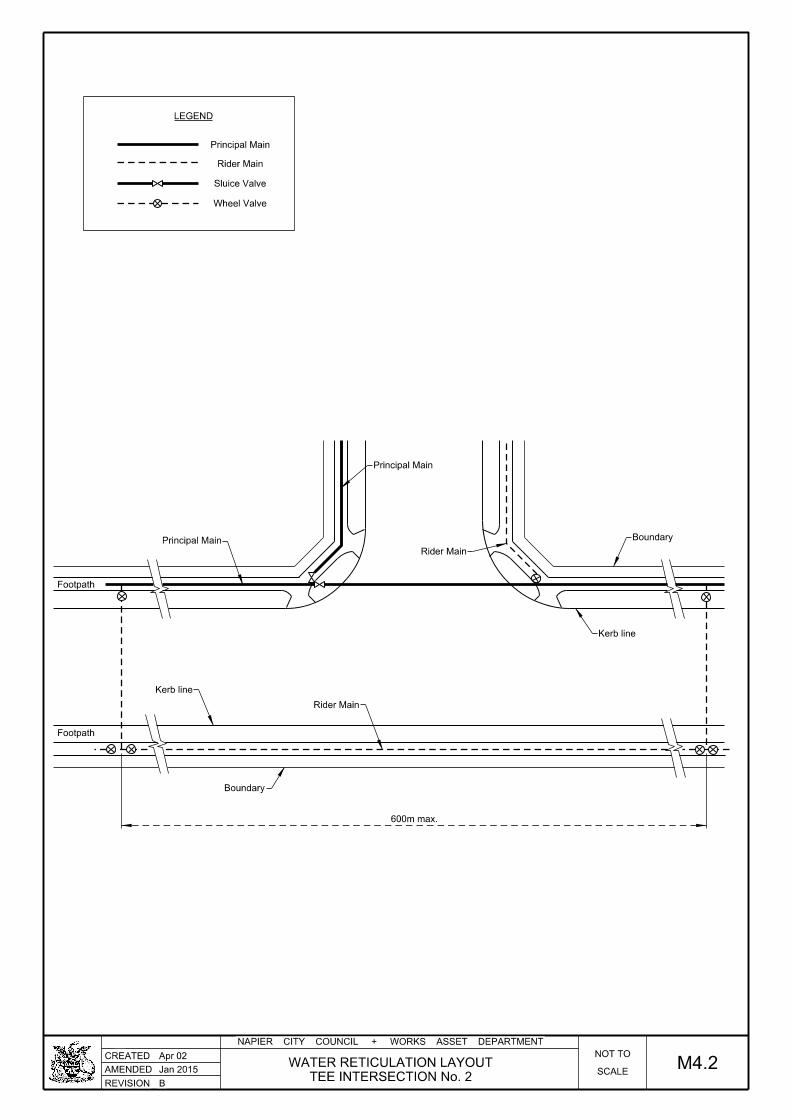
REVISION
NAPIER CITY COUNCIL + WORKS ASSET DEPARTMENT
CREATED
AMENDED
B
Apr 02
Jan 2015 SCALE
NOT TO
TEE INTERSECTION No. 2
WATER RETICULATION LAYOUT M4.2
Footpath
Footpath
Rider Main
Principal Main
Boundary
Kerb line
Rider Main
Boundary
Kerb line
Principal Main
600m max.
Principal Main
Rider Main
Sluice Valve
Wheel Valve
LEGEND

REVISION
NAPIER CITY COUNCIL + WORKS ASSET DEPARTMENT
CREATED
AMENDED
B
Apr 02
Jan 2015 SCALE
NOT TO
CROSS INTERSECTION
WATER RETICULATION LAYOUT M4.3
Footpath
Footpath
Boundary
Rider Mains
Kerb line
Kerb line
Boundary
Principal Main
Principal Main
Rider Main
Sluice Valve
Wheel Valve
LEGEND

REVISION
NAPIER CITY COUNCIL + WORKS ASSET DEPARTMENT
CREATED
AMENDED
B
Apr 02
Jan 2015 SCALE
NOT TO
CUL-DE-SAC
WATER RETICULATION LAYOUT M4.4
Principal Main
Rider Main
Sluice Valve
Wheel Valve
Fire Hydrant
ConnectionService
LEGEND
Refer to M4.5

REVISION
NAPIER CITY COUNCIL + WORKS ASSET DEPARTMENT
CREATED
AMENDED
B
Apr 02
Whole numbers = mm. Decimalised expressions = m.NOTE:
Jan 2015 SCALE
NOT TO
TO PRINCIPAL MAIN - CUL DE SAC
CONNECTION OF RIDER MAIN M4.5
600
max.
Terminal Fire H
ydra
nt.
top of
wheel.
exte
nd b
elo
wP
VC pipe to
Polyeth
yle
ne Rider
Main.
hydra
nt box a
nd s
urrounds.
Pipe p
ulled clear of
or similar
Elo
ngate
d gibault joint
1m minim
um
0.5
m m
axim
um

REVISION
NAPIER CITY COUNCIL + WORKS ASSET DEPARTMENT
CREATED
AMENDED
B
Apr 02
Jan 2015 SCALE
NOT TO
TO PRINCIPAL MAIN - TEE INTERSECTION
CONNECTION OF RIDER MAIN M4.6
top of wheel valve.PVC pipe to extend below
or other approved.Elongated gibault joint
Principal Main.

REVISION
NAPIER CITY COUNCIL + WORKS ASSET DEPARTMENT
CREATED
AMENDED
B
Apr 02
Jan 2015 SCALE
NOT TO
TO PRINCIPAL MAIN - CROSS INTERSECTION
CONNECTION OF RIDER MAIN M4.7
top of wheel valvePVC pipe to extend below
or other approved Elongated gibault joint
Principal Main.

REVISION
NAPIER CITY COUNCIL + WORKS ASSET DEPARTMENT
CREATED
AMENDED
B
Apr 02
Whole numbers = mm. Decimalised expressions = m.NOTE:
Jan 2015 SCALE
NOT TO
SERVICE CONNECTION DETAIL M4.8
Boundary
250 50 cover+-
Carriageway.
Kerb and Channel.
footpath
manifold.
Watermain
750 min. cover
1800
from boundarymax. 300mm
min. 150
Ground Level
600 min. cover
see detailStandard manifold box
STANDARD MANIFOLD DETAIL

REVISION
NAPIER CITY COUNCIL + WORKS ASSET DEPARTMENT
CREATED
AMENDED
B
Apr 02
Whole numbers = mm. Decimalised expressions = m.NOTE:
Jan 2015 SCALE
NOT TO
WATERMAIN THRUST BLOCKS M4.9
Dimensions L and H should be sized specifically.
L may be up to 1.4 times H. C should generally be approximately 50% of L.
1.
2.
3.
Thrust block concrete should be kept clear of all pipe joints and should not encase
beyond the point of max pipe diameter.
Uplift thrusts do not develop soil bearing pressure in this way and they must be
designed specifically.
For uplift thrusts the total thrust must be held by the mass of the thrust block and
galvanised steel tension straps shall be used to hold the pipe to the thrust block.
4.
5.
Y Y
XX
LL
Equal
Equal
H
C
60°
Angle of bend
60°
C
Equal
Equal
H
be kept clear of jointsConcrete always to
Concrete always to be kept clear of joints
fot THRUST BLOCK measurementsThe internal dia. of this pipe to be used
All unbalanced forces to be restrained
All bolts shall be positioned such that bolts could be replaced.
All bearing faces of the thrust blocks to be poured against natural ground.
6.
PLAN
SECTION X-X
SECTION Y-Y
PLAN
Notes:
HORIZONTAL BEND
TEE OR END CAP
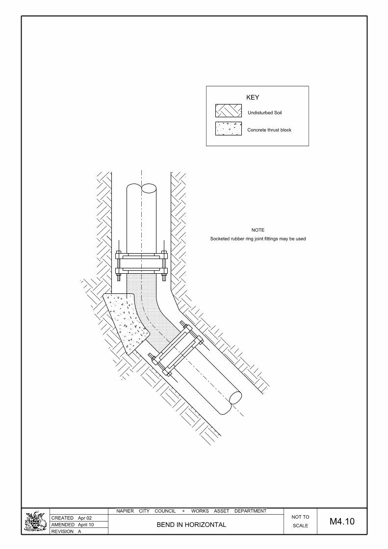
REVISION
NAPIER CITY COUNCIL + WORKS ASSET DEPARTMENT
CREATED
AMENDED
A
Apr 02
April 10 SCALE
NOT TO
BEND IN HORIZONTAL M4.10
Undisturbed Soil
Concrete thrust block
Socketed rubber ring joint fittings may be used
NOTE
KEY

REVISION
NAPIER CITY COUNCIL + WORKS ASSET DEPARTMENT
CREATED
AMENDED
A
Apr 02
April 10 SCALE
NOT TO
TEE ANCHORAGE M4.11
NOTE
Socketed rubber ring joint fittings may be used
Undisturbed soil
Concrete thrust block
KEY
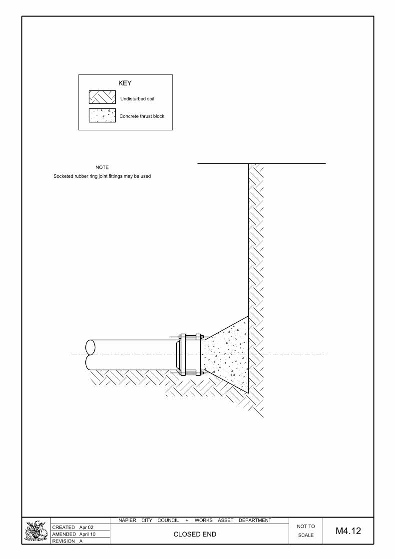
REVISION
NAPIER CITY COUNCIL + WORKS ASSET DEPARTMENT
CREATED
AMENDED
A
Apr 02
April 10 SCALE
NOT TO
CLOSED END M4.12
Undisturbed soil
Concrete thrust block
NOTE
Socketed rubber ring joint fittings may be used
KEY

REVISION
NAPIER CITY COUNCIL + WORKS ASSET DEPARTMENT
CREATED
AMENDED
B
Apr 02
Whole numbers = mm. Decimalised expressions = m.NOTE:
Jan 2015 SCALE
NOT TO
FIRE HYDRANT INSTALLATION M4.13
MAINMAIN
300 min.
TALL OR MEDIUM HYDRANT
min.
Sub-base
Basecourse
200
in direction of main)Fire hydrant lid (lid orientated in
25mm Ashphaltic concrete
Saw cut
surfaceExisting sealed
road crossfall sloperisers if required to achieveMortar between these two
max. = 400mmmin. = 100mm
possibleMinimum 3 whereConcrete risers
compacted metal100mm thick
M4 BasecourseCompacted
Risers to suit site conditions
Top of spin
dle

REVISION
NAPIER CITY COUNCIL + WORKS ASSET DEPARTMENT
CREATED
AMENDED
A
Apr 02
Whole numbers = mm. Decimalised expressions = m.NOTE:
April 10 SCALE
NOT TO
LINE VALVE INSTALLATION M4.14
min.
Basecourse
Sub-Base
thrustdesign
over 300 min.Feathered surface
forAs req'd
length as shown to protect the spindlePVC pipe shall be installed and cut toFor deep valves, a 150mm (minimum)
200 min 500 min
200
(lid in direction of pipe)N.C.C approved valve box lid
25mm Asphaltic concrete
Saw cut
Concrete thrust block
Puddle flangefrom API linepipefabricatedSteel special
basecourseCompacted M4
road crossfall sloperisers if required to achieveMortar between these two
road crossfall sloperisers if required to achieveMortar between these two
minimum 2Concrete risers
compacted metals100mm thick

REVISION
NAPIER CITY COUNCIL + WORKS ASSET DEPARTMENT
CREATED
AMENDED
A
Apr 02
Whole numbers = mm. Decimalised expressions = m.NOTE:
April 10
and the Utilities Access ActSurface cover and frame to comply with AS 3996 (Class D)
Maximum sizes taken from NZS 4522:2010
SCALE
NOT TO
FIRE HYDRANT BOX M4.15
FH
40413 13
150
4244642
13
30 30
39532
20
13
530
380
30
40
1050
380
70 min.
B
A
B
A

REVISION
NAPIER CITY COUNCIL + WORKS ASSET DEPARTMENT
CREATED
AMENDED
A
Apr 02
Whole numbers = mm. Decimalised expressions = m.NOTE:
April 10 SCALE
NOT TO
FIRE HYDRANT BOX DETAILS M4.16
SE
CTIO
N A - A LID
SE
CTIO
N B - B LID
PL
AN - U
ND
ER
SID
E O
F LID
SE
CTIO
N B - B
398
25
157
30
157
25
394
20
12
398
250
25
25 25
10
40
30
42
296
42
150
254
13
13
247
30
13
250
12
222
12
245
230 min.
A
B B
A

REVISION
NAPIER CITY COUNCIL + WORKS ASSET DEPARTMENT
CREATED
AMENDED
A
Apr 02
Whole numbers = mm. Decimalised expressions = m.NOTE:
April 10 SCALE
NOT TO
VALVE BOX M4.17
SVNAPIER
SECTION A - A
PLAN
340
385
4030540
30 30
1125311
245
225
11
25
11
12
18011
30
22
28
20
3
70 min. AA
B
B

REVISION
NAPIER CITY COUNCIL + WORKS ASSET DEPARTMENT
CREATED
AMENDED
A
Apr 02
Jun 07
Whole numbers = mm. Decimalised expressions = m.NOTE:
SCALE
NOT TO
VALVE BOX DETAILS M4.18
SE
CTIO
N A - A LID
SE
CTIO
N B - B LID
SE
CTIO
N B - B
PL
AN U
ND
ER
SID
E O
F LID
250
243
200
193
8
15
25
200
250
11
11
6
30
35
30
30
40
260
40
175
195
203
11
11
11
11

REVISION
NAPIER CITY COUNCIL + WORKS ASSET DEPARTMENT
CREATED
AMENDED
A
Apr 02
Jun 07
Whole numbers = mm. Decimalised expressions = m.NOTE:
SCALE
NOT TO
TOBY BOX DETAILS M4.19
LID
SECTION
PLAN
120
12
12
3014030
2525
100
712277
7
200
200
94
92
6
requires specific approval.is restricted andUse of these boxes

REVISION
NAPIER CITY COUNCIL + WORKS ASSET DEPARTMENT
CREATED
AMENDED
A
Apr 02
Jun 07
Whole numbers = mm. Decimalised expressions = m.NOTE:
SCALE
NOT TO
HYDRANT SURROUND (CONCRETE) M4.20
400 100 ± 10
100 ± 1
0250
100 ± 1
0
Wire reinforcing.
20MPa at 28 days

REVISION
NAPIER CITY COUNCIL + WORKS ASSET DEPARTMENT
CREATED
AMENDED
A
Apr 02
Jun 07
Whole numbers = mm. Decimalised expressions = m.NOTE:
SCALE
NOT TO
VALVE SURROUND (CONCRETE) M4.21
70 ± 1
0200
100 ± 1
0
70 ± 10200
Wire reinforcing.
20MPa at 28 days

REVISION
NAPIER CITY COUNCIL + WORKS ASSET DEPARTMENT
CREATED
AMENDED
B
Apr 02
Whole numbers = mm. Decimalised expressions = m.NOTE:
Jan 2015 SCALE
NOT TO
MANIFOLD BOX M4.22
215
2505 5
2534525
300
395
55
250
5
30
min
Polyethylene boxes not to be used in carriageways4.
Covers to be painted blue or left black3.
Letters and pattern to be raised 3mm2.
high density polyethylene.Manifold box material shall be1.
NOTES:
B
B
AA
SECTION A - A
PLAN
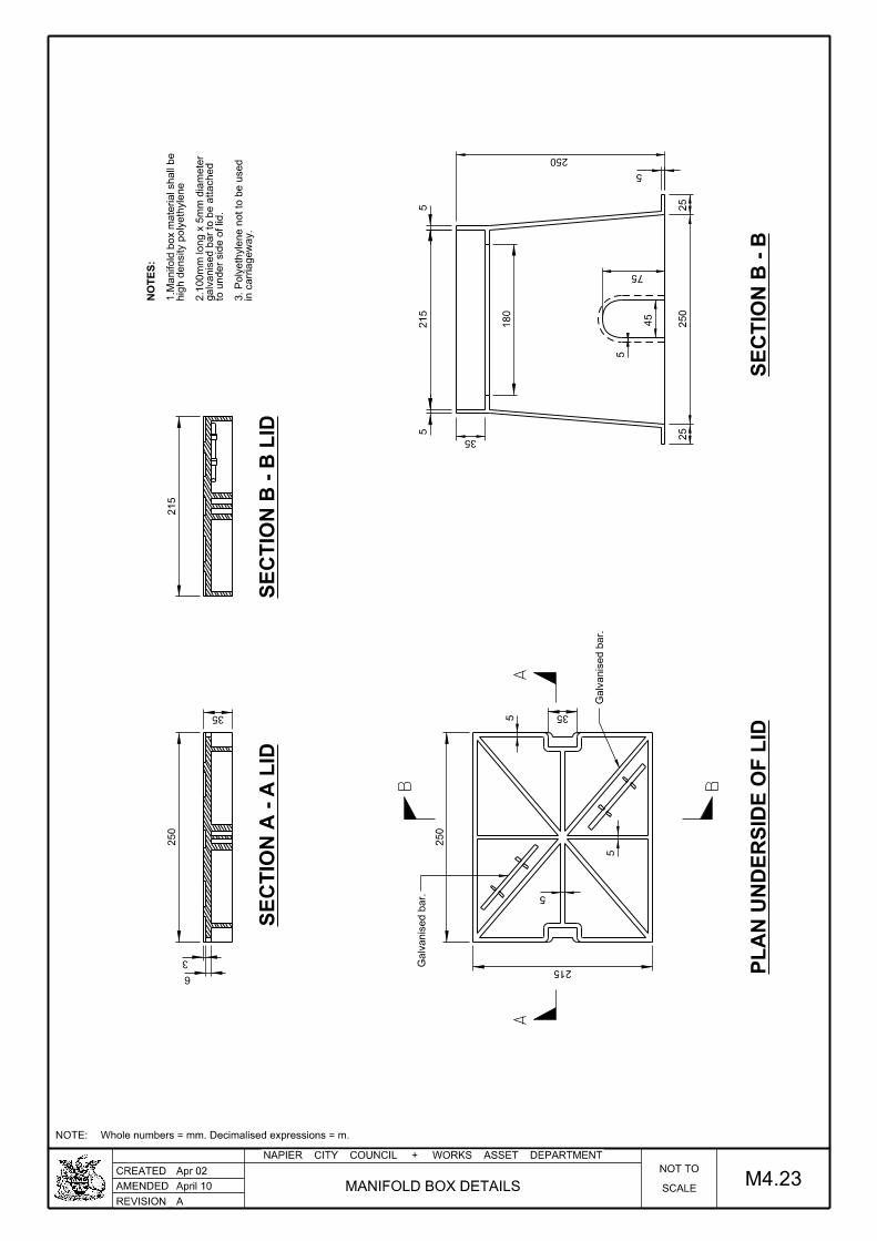
REVISION
NAPIER CITY COUNCIL + WORKS ASSET DEPARTMENT
CREATED
AMENDED
A
Apr 02
Whole numbers = mm. Decimalised expressions = m.NOTE:
April 10 SCALE
NOT TO
MANIFOLD BOX DETAILS M4.23
250
6
3
35
215
250
215
35
215
55
35
25
250
25
45
75
5
250
5
5
5
5
Galvanised b
ar.
Galvanised b
ar.
180
in carria
ge
way.
3. Polyeth
yle
ne n
ot to b
e used
to u
nder side of lid.
galvanised b
ar to b
e attached
2.1
00
mm long x 5
mm dia
meter
hig
h d
ensity p
olyeth
yle
ne
1.M
anifold b
ox m
aterial shall b
e
NO
TE
S:
SE
CTIO
N B - B LID
SE
CTIO
N A - A LID
PL
AN U
ND
ER
SID
E O
F LID
SE
CTIO
N B - B

REVISION
NAPIER CITY COUNCIL + WORKS ASSET DEPARTMENT
CREATED
AMENDED
B
Mar 10
Whole numbers = mm. Decimalised expressions = m.NOTE:
Jan 2015 SCALE
NOT TO
BACKFLOW PREVENTER ASSEMBLY M4.24
FL
OW
ME
TE
R
Vent
M & F elb
ow.
FL
OW
Gate valve.
Strainer.
or similar
MA
C U
nio
ns
or double c
heck valves
R.P.Z.
Back flo
w pre
venter
Resilie
nt seate
d valve.
300min.
100
min. 300 wide

REVISION
NAPIER CITY COUNCIL + WORKS ASSET DEPARTMENT
CREATED
AMENDED
B
Mar 10
Whole numbers = mm. Decimalised expressions = m.NOTE:
Jan 2015 SCALE
NOT TO
HOSE TAP SPECIFICATION M4.25
Finished Soil Level
0.5
0min
Pipe clamps
Copper or polyethylene pipe
300
min
Manifold with meter
Concrete around post
100 x 100 H3 Post.
100 x 100 H3 Post via wingback"Lockshield" tap screwed to

Compacted Metal Base
Finished Ground Level
MetalMixed
Compacted
300 min clear
Around PipeEpoxy Mortar
DN 80 Isolating Valve
Double or Single Air Valve
conditions on sitebe required depending onConcrete Base may not
600dia. Manhole Lid
200min.
REVISION
NAPIER CITY COUNCIL + WORKS ASSET DEPARTMENT
CREATED
AMENDED
B
Jan 2015
April 10
SCALE
NOT TO
AIR VALVE DETAIL M4.26
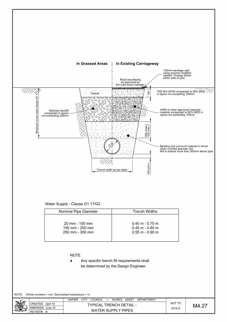
either side of jointsealant. Overlap 50mm using polymer modified100mm bandage seal
D
Nominal Pipe Diameter Trench Widths
250 mm - 300 mm
150 mm - 200 mm
20 mm - 100 mm
0.55 m - 0.90 m
0.45 m - 0.80 m
0.40 m - 0.75 m
Water Supply - Clause G1.17/G2
REVISION
NAPIER CITY COUNCIL + WORKS ASSET DEPARTMENT
CREATED
AMENDED
B
Whole numbers = mm. Decimalised expressions = m.NOTE:
June 15
April 10
SCALE
NOT TO
M4.27WATER SUPPLY PIPES
TYPICAL TRENCH DETAIL -
Topsoil in layers not exceeding 150mmTNZ M/4 AP40 compacted to 98% MDD
Trench width as per table
150
Minim
um c
over (s
ee cla
use G
1.1
7)
the road asset manageras approved by
Road resurfacing
100 (
min.)
100 (
min.)
300 (
max.)
In Grassed Areas
be determined by the Design Engineer.
Any specific trench fill requirements shall●
NOTE
not exceeding 200mmcompacted in layers
Selected backfill
In Existing Carriageway
layers not exceeding 150mmmaterial compacted to 95% MDD inAP65 or other approved imported
Not to extend more than 300mm above pipeclean rounded granular mix.Bedding and surround material 5-14mm

CODE OF PRACTICE FOR SUBDIVISION Part M –Appendices
AND LAND DEVELOPMENT
Napier City Council JULY 2015 M-161
M5. STANDARD FORMS: ROADING
Page No. Description
Appendix M5.1 Pavement Information Sheet
Appendix M5.2 RAMM Update : Surfacing Information
Appendix M5.3 RAMM Update : Pre-seal Repairs Pavement Information
Appendix M5.4 RAMM Update : Pavement Marking
Appendix M5.5 Schedule 1C : Certificate upon Completion of Land Development / Subdivision
Work
Appendix M5.6 Roading Inspection and Testing Schedule

CODE OF PRACTICE FOR SUBDIVISION Part M –Appendices
AND LAND DEVELOPMENT
Napier City Council JULY 2015 M-162
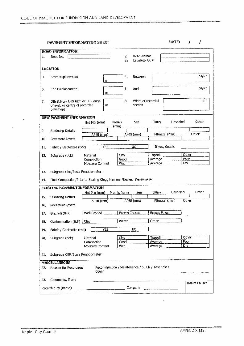
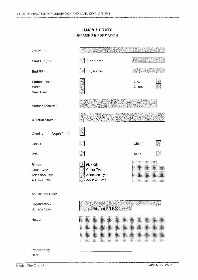

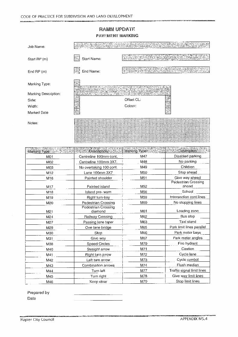


CODE OF PRACTICE FOR SUBDIVISION Part M –Appendices
AND LAND DEVELOPMENT
Napier City Council JULY 2015 M-163
M6. DRAUGHTING SYMBOLS AND CODES
Drawing No. Description
M6.1 Standard Symbols and GIS Codes

CODE OF PRACTICE FOR SUBDIVISION Part M –Appendices
AND LAND DEVELOPMENT
Napier City Council JULY 2015 M-164
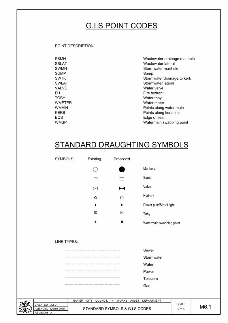
REVISION
NAPIER CITY COUNCIL + WORKS ASSET DEPARTMENT
CREATED
AMENDED
A
Jul 01
M6.1N.T.S
SCALE
POINT DESCRIPTION:
Watermain swabbing point
Edge of seal
Points along kerb line
Points along water main
Water meter
Water toby
Fire hydrant
Water valve
Stormwater lateral
Stormwater drainage to kerb
Sump
Stormwater manhole
Wastewater lateral
Wastewater drainage manhole
SYMBOLS: Proposed
LINE TYPES:
Gas
Telecom
Power
Water
Stormwater
Sewer
STANDARD DRAUGHTING SYMBOLS
Existing
G.I.S POINT CODES
WMSP
EOS
KERB
WMAIN
WMETER
TOBY
FH
VALVE
SWLAT
SWTK
SUMP
SWMH
SSLAT
SSMH
STANDARD SYMBOLS & G.I.S CODES
Watermain swabbing point
Toby
Power pole/Street light
Hydrant
Valve
Sump
Manhole
March 2015

CODE OF PRACTICE FOR SUBDIVISION Part M –Appendices
AND LAND DEVELOPMENT
Napier City Council JULY 2015 M-165
M7. GLOSSARY OF STANDARDS / GUIDANCE NOTES
Issuer Number Year Title
AS 1628 1999 Water Supply: Metallic Gate, Globe, and Non-Return Valves
AS 1722.1 1975 Pipe Threads of Whitworth Form - Sealing Pipe Threads
AS 1722.2 1975 Pipe Threads of Whitworth Form - Fastening Pipe Threads
AS 2345 2006 Dezincification Resistance of Copper Alloys
AS 2638.2 2011 Sluice Valves for Waterworks Purposes Part 2 Resilient Seated
AS 4087 2004 Metallic Flanges for Waterworks Purposes
ASME B 16.9 2004 Wrought Steel Butt-Welding Fittings
AS/NZS 1158 2005 Road Lighting
AS/NZS 1254 2010 PVC Pipes and Fittings for Stormwater and Surface Water Applications.
AS/NZS 1260 2009 PVC-U Pipes and Fittings for Drain, Waste and Vent Applications
AS/NZS 1477 2006 PVC Pipes and Fittings for Pressure Applications
AS/NZS 1546.1 2008 On-Site Domestic Wastewater Treatment Units, Part 1: Septic Tanks
AS/NZS 1547 2012 On-Site Domestic Wastewater Management
AS/NZS 1646 2007 Elastomeric Seals for Waterworks Purposes
AS/NZS 2041.4 2010 Buried Corrugated Metal Structures, Part 4: Helically formed sinusoidal
pipes
AS/NZS 2032 2006 Installation of PVC Systems
AS/NZS 2033 2008 Installation of Polyethylene Pipe Systems
AS/NZS 2280 2004 Ductile Iron Pipes and Fittings
AS/NZS 2566.1 1998 Buried Flexible Pipelines: Part 1 - Structural Design
AS/NZS 2566.2 2002 Buried Flexible Pipelines: Part 2 - Installation
AS/NZS 2845.1 2010 Water Supply-Backflow Prevention Devices: Part 1: Materials, Design and
Performance Requirements
AS/NZS 2845.2 2010 Water Supply-Backflow Prevention Devices Part 2: Air Gaps and Break
Tanks
AS/NZS 2845.3 2010 Water Supply-Backflow Prevention Devices Part 3: Field Testing and
Maintenance
AS/NZS 3500.1 2003 National Plumbing and Drainage Code Part 1 – Water Services
AS/NZS 3518 2004 ABS Compounds, Pipes and Fittings for Pressure Applications
AS/NZS 3725 2007 Design for Installation of Buried Concrete Pipes
AS/NZS 3879 2011 Solvent Cements and Priming Fluids for PVC (PVC-U and PVC-M) and ABS
Pipes and Fittings
AS/NZS 4058 2007 Precast Concrete Pipes (Pressure and Non-Pressure)".
AS/NZS 4129 2008 Fittings for Polyethelene (PE) Pipes for Pressure Applications
AS/NZS 4130 2009 Polyethylene (PE) Pipes for Pressure Applications
AS/NZS 4131 2010 Polyethylene (PE) Components for Pressure Pipes and Fittings
AS/NZS 4455.1 2008 Masonry Units, Pavers, Flags, and Segmental Retaining Wall Units
Part 1: Masonry Units
AS/NZS 4455.2 2010
Masonry Units, Pavers, Flags, and Segmental Retaining Wall Units
Part 2: Pavers and Flags
AS/NZS 4455.3 2008
Masonry Units, Pavers, Flags, and Segmental Retaining Wall Units
Part 3: Segmental retaining Wall Units
AS/NZS 4519 1977 Abrasive Grains - Determination of Capilliarity
AS/NZS 4680 2006 Hot-Dip Galvanised (Zinc) Coatings of Fabricated Ferrous Articles

CODE OF PRACTICE FOR SUBDIVISION Part M –Appendices
AND LAND DEVELOPMENT
Napier City Council JULY 2015 M-166
Issuer Number Year Title
AS/NZS 4765 2007 Modified PVC (PVC-M) Pipes for Pressure Applications
ASTM A106.99e 1999 ASTM A106-99e1 Grade B Schedule 40 (API Line Pipe).
BS 21 1985 Pipe Threads for Tubes and Fittings
BS 2799 1986 Specification for Pipe Threads for Tubes and Fittings where Pressure-
Tight Joints are Not Made on the Threads
BS EN 598 2007 Ductile Iron Pipes, Fittings, Accessories and their Joints for Sewerage
Applications - Requirements and Test Methods
BS EN 1982 1999 Copper and Copper Alloys, Ingots and Castings
BS EN 14364 2006 Plastic Piping Systems for Drainage and Sewerage With or Without
Pressure
ISO 4064 2014 Water meters for cold potable water and hot water
OIML R-49 2013 Water meters for cold potable water and hot water
NZS 3103 1991 Specification for Sands for Mortars and Plasters
NZS 3104 2003 Specification for Concrete Production
NZS 3106 2009 Code of Practice for Concrete Structures for the Storage of Liquids
NZS 3109 1997 Concrete Construction
NZS 3114 1987 Concrete Surface Finish
NZS 3116 2002 Concrete Segmental Paving (Part 2 superseded by AS/NZS 4455)
NZS 3124 1987 Concrete for Small Works
NZS 3501 1976 Specification for Copper Tubes for Water, Gas, and Sanitation
NZS 4121 2001 Design for Access and Mobility - Buildings and Associated Facilities
NZS 4402 1986 Methods of Testing Soils for Civil Engineering Purposes
NZS 4406 1986 Helical Lock-Seam Corrugated Steel Pipes - Design and Installation
NZS 4431 1989 Code of Practice for Earth Fill for Residential Development
NZS 4442 1988 Welded Steel Pipes and Fittings for Water, Sewage and Medium Pressure
Gas
NZS 4522 2010 Underground Fire Hydrants
NZS 7601 1978 Specification for Polyethylene Pipe (Type 3) for Cold Water Services
NZS 7602 1977 Specification for Polyethylene Pipe (Type 5) for Cold Water Services
NZS/AS 3725 2007 Design for Installation of Buried Concrete Pipes (and
Supplement/Commentary to NZS AS 3725)
TNZ B/2 2005 Construction of Unbound Granular Pavement Layers
TNZ F/1 1997 Specification for Earthworks Construction
TNZ F/2 2008 Specification for Pipe Subsoil Drain Construction
TNZ F/3 2010 Specification for Pipe Culvert Construction
TNZ M/1 2011 Specification for Roading BItumens
TNZ M/3 1986 Sub-base Aggregate
TNZ M/4 2006 Basecourse Aggregate
TNZ M/6 2011 Sealing Chip
TNZ M/7 2009 Roadmarking Paints
TNZ M/10 2005 Asphaltic Concrete
TNZ P/3 1995 First Coat Sealing
TNZ P/4 1995 Resealing
TNZ P/9 1975 Construction of Asphaltic Concrete Paving
TNZ P/12 2000 Pavement Marking

CODE OF PRACTICE FOR SUBDIVISION Part M –Appendices
AND LAND DEVELOPMENT
Napier City Council JULY 2015 M-167
M8. SUBJECT INDEX
DESCRIPTION ASSET / ACTIVITY SUBJECT CLAUSE
Acceptance of Installation Utility Services Cable Services K1.6
Access Chambers Wastewater Design H1.10
Wastewater Construction H2.11 / 2.16
Stormwater Design I1.14
Stormwater Construction I2.10
Anti-Scour Blocks Water Supply Design G1.11
Wastewater Design H1.5.2
Apartment Complexes Residential Subdivisions Design J2
Application of Specifications Earthworks Construction E2.3
Approvals Water Supply Design G1.3
Wastewater Design H1.3
Stormwater Design I1.3
Approved Construction Drawings Wastewater Construction H2.2
As-Built document requirements Earthworks Construction E2.12
Roading Construction F2.15
Water Supply Construction G2.14
Wastewater Construction H2.17
Stormwater Construction I2.16
As-Built Information Requirements Roading General M1.5
Stormwater General M1.4
Wastewater General M1.3
Water Supply General M1.2
As-Built Plans Requirements All General M1.1
Assessment Criteria Subdivision /Land Development Resource Management A8
Asset Valuation Format Subdivision /Land Development Resource Management Appendix A1
Backfilling Stormwater Construction I2.13
Backfilling of Trenches Wastewater Construction H2.14
Backflow Effects Stormwater Design I1.13
Batters - General Roading Design E1.8
Batters: Blending Earthworks Design E1.10
Batters: Filling Earthworks Design E1.8
Batters: Surface protection Earthworks Design E1.11
Batters; Cutting Earthworks Design E1.9
Benchmarks Roading Construction F2.12.4
Berms and Trees Roading Construction F2.11
Blending of Batters Earthworks Design E1.10
Cable-type Services Utility Services Design K1
Car Parking Roading Design F1.13
Catchments Stormwater Design I1.7
CCTV Wastewater Construction H2.15

CODE OF PRACTICE FOR SUBDIVISION Part M –Appendices
AND LAND DEVELOPMENT
Napier City Council JULY 2015 M-168
DESCRIPTION ASSET / ACTIVITY SUBJECT CLAUSE
Code Overview Code Overview All D1, D2
Communal Water Supplies Water Supply Design G1.20.4
Completion Documentation All General M1.6
Completion of Earthworks Earthworks Construction E2.1
Concrete and mortar Stormwater Design I1.21.4
Connections Wastewater Design H1.9
Stormwater Design I1.19
Stormwater Construction I2.9
Wastewater Construction H2.10
Connections (Subdivisions) Stormwater Design J1.4
Connections to City supply Water Supply Construction G2.13
Consents for Connection Water Supply Design G1.3
Wastewater Design H1.3
Stormwater Consents for Connection I1.3
Construction Monitoring Engineering Performance Criteria Engineering Performance B7
Construction of Fills Earthworks Construction E2.9
Construction Report Earthworks Construction E2.11
Construction Requirements Engineering Performance Criteria Engineering Performance B6
Contamination of pipes Wastewater Wastewater H2.9
Stormwater Construction I2.8
Control of Wastewater Flows Wastewater Wastewater H2.5
Control of Water Water Supply Construction G2.5
Wastewater Construction H2.4
Stormwater Construction I2.4
Controlled Activities Land Development Resource Management A 6.1
Cover to Pipes Water Supply Design G1.18
Wastewater Design H1.5.1
Stormwater Design I1.17.1
Cut batters Earthworks Design E1.9
Definitions, Background, Scope Code Definitions Resource Management A1 - A3
Design Engineering Performance Criteria Engineering Performance B5
Design & Flow Wastewater Design H1.4
Design and Flow requirements Wastewater Design H1.4
Design parameters Wastewater Design H1.11
Design pressures Water Supply Design G1.6
Design Return Periods Stormwater Design I1.4
Design Standards Roading Engineering Standards Appendix C1
Design Standards Roading Design Table F-1
Design Standards Water Supply Design G1.5
Discretionary Activities Subdivision / Land Development Resource Management A6.3
Disinfection Water Supply Construction G2.12

CODE OF PRACTICE FOR SUBDIVISION Part M –Appendices
AND LAND DEVELOPMENT
Napier City Council JULY 2015 M-169
DESCRIPTION ASSET / ACTIVITY SUBJECT CLAUSE
Disposal Wastewater Design H1.16
Drainage / Silt Control Stormwater Construction E2.6
Draughting Symbols and GIS Codes All General M6
Dust Control Earthworks Construction E2.7
Earthworks Engineering Performance Criteria Engineering Performance B8
Residential Subdivisions Design J1.2
Engineering Standards Engineering standards C5.5
Easements Stormwater Easements C5.4.3/4
Wastewater Engineering Standards C5.4.3 / 5.4.4
Water Supply Engineering Standards C5.4.3 / 5.4.4
Subdivisions Design J1.4
Electrical Utility Services Cable Services K1.3
Electrical Plant Utility Services Cable Services K1.5
Electrical Power Engineering Performance Criteria Engineering Performance B16
Engineering Approval Requirements Subdivision / Land Development Documentation A7.2.5
Engineering Performance Criteria: Engineering Performance Criteria Engineering Performance B1 & 2
Environmental Outcomes Engineering Performance Criteria Engineering Performance B3
Esplanade Reserves Subdivision / Land Development Resource Management Appendix A4
& A5
Excavation Earthworks Construction E2.8
Fill Batters Earthworks Design E1.8
Fill densities Earthworks Design E1.7
Finished levels: Roads / Lots Roading Design E1.12
Fire Hydrant Location Water Supply Design G1.13
Flood Attenuation Stormwater Design I1.6
Flood Control Engineering Performance Criteria Engineering Performance B12
Flow Control Wastewater Construction H2.5
Flow Requirements Wastewater Design H1.4
Footpaths Roading Construction F2.8
Gas Engineering Performance Criteria Engineering Performance B18
Gas Plant & Pipeworks Utility Services Gas Reticulation K2.4
Gas Reticulation: General Utility Services Gas Reticulation K2.1
General Earthworks Construction E2.1
General / Definitions Engineering Standards Engineering Standards C1 / C2
General Criteria Engineering Performance Criteria Engineering Performance B4
General Requirements Water Supply Design C1.4
Geotechnical investigations Earthworks Design E1.3
Geotechnical Monitoring Earthworks Construction E2.5
Glossary of Standards / Guidance Notes All General M7
Infiltration Wastewater Design H1.14
Information Cabling Engineering Performance Criteria Engineering Performance B19
Information Cabling Utility Services Cable Services K1.3

CODE OF PRACTICE FOR SUBDIVISION Part M –Appendices
AND LAND DEVELOPMENT
Napier City Council JULY 2015 M-170
DESCRIPTION ASSET / ACTIVITY SUBJECT CLAUSE
Inlet and Outlet Structures Stormwater Construction I2.11
Inspection & Testing Schedule Roading Construction Appendix
M5.6
Inspections Roading Construction F2.14
Inspections by Council Water Supply Construction G2.3
Wastewater Construction H2.13
Stormwater Construction I2.12
Subdivision / Land Development Resource Management Appendix A2
Kerbs and Channels Roading Construction F2.9
Land and Building Sites Stormwater Design I1.4.2
Land Development: Flood Levels Stormwater Design I1.4.2
Land Development: Ponding & Floor
Levels Stormwater Design I1.1.3c
Land Suitability (Prof. opinion) Earthworks Resource Management A8, A9
Location of Wastewater Mains Wastewater Design H1.8
Lot drainage sumps Earthworks Design E1.12
Mail Boxes Residential Subdivisions Design J1.8
Mains Sizing Water Supply Design G1.8
Management Strategies (Objectives &
Policies) Subdivision / Land Development Resource Management A5
Mass Earthfills Earthworks Design E1.6
Material Condition Water Supply Construction G2.6
Materials Roading Design F1.11
Wastewater Design H1.13
Stormwater Design I1.21
Water Supply Design G1.19
Minimum Protection Criteria Stormwater Design I1.4
Minimum Requirements Subdivision & Land Development Engineering Standards C4
Individual Services & Utilities Engineering Standards C5
Multi-Storey Buildings / Apartment
Complexes Residential Subdivisions Design J2
Network Utilities and Services Engineering Standards Engineering standards C5.4
Non Public Accessways Engineering Performance Criteria Engineering Performance B10
Non Public Accessways Roading Design F1.12
Non Reticulated areas Water Supply Design: G1.20
Non-Reticulated Wastewater Systems Wastewater Engineering Performance B14
Objectives / Performance Criteria Earthworks Engineering Performance B8
Objectives / Performance Criteria Electrical Power Engineering Performance B16
Gas Reticulation Engineering Performance B18
Information Cabling Engineering Performance B19
Stormwater Engineering Performance B12
Telecommunications Engineering Performance B19
Roading Engineering Performance B9 - B11, B20
On-Lot Treatment and Disposal Wastewater Design H1.15
On-Site Access Engineering Standards Engineering standrads C5.7

CODE OF PRACTICE FOR SUBDIVISION Part M –Appendices
AND LAND DEVELOPMENT
Napier City Council JULY 2015 M-171
DESCRIPTION ASSET / ACTIVITY SUBJECT CLAUSE
Open channels Stormwater Design I1.12
Open Drains Stormwater Design I1.8
Other Utility Services Engineering Standards Engineering standrads C5.13
Ownership Transfer Agreement Subdivision / Land Development Resource Management App. A3
Pavement Structural Design Roading Design F1.7
Pipe Condition Wastewater Construction H2.6
Stormwater Construction I2.5
Pipe Design Wastewater Design H1.12
Stormwater Design I1.11 / I1.17
Pipe Jointing Wastewater Construction H2.8
Stormwater Construction I2.7
Pipe Laying Water Supply Construction G2.8
Wastewater Construction H2.7
Stormwater Construction I2.6 / 2.7
Pipe materials Wastewater Design H1.13
Stormwater Design I1.21.1
Pipe Roughness and grades Wastewater Design H1.12
Pipe strength and bedding Stormwater Design I1.21.2
Pipe Suitability and Protection Criteria Wastewater Design H1.6
Pipe Supports / Anti-scour Blocks Water Supply Design G1.11
Piped Drains and Culverts Stormwater Design I1.11
Pipelaying requirements Water Supply Construction G2.8
Precast access chambers Stormwater Design I1.21.3
Primary Protection Wastewater Design I1.2
Private Ways, Formed Accessways,
Driveways Roading Design F1.12
Residential Subdivisions Design J1.3
Pumping of Stormwater Stormwater Design I1.18
Pumping Stations & Pressure Mains Wastewater Design H1.7
Rainfall Intensity Stormwater Design I1.10
Recreational reserves Engineering Performance Criteria Engineering Performance B23
Refuse Disposal Facilities Residential Subdivisions Design J1.7
Refuse Disposal Facilities Residential Subdivisions Design J2.4
Relative Road / Lot heights Stormwater Design E1.12
Reserves Engineering Standards Engineering standrads C5.12
Reservoirs (Storage) Water Supply Design G1.16
Reservoirs (Supply Pumps) Water Supply Design G1.17
Residential Subdivisions Residential Subdivisions Design J 1.1 – 1.8
Resource Consent Application Procedure Subdivisions Resource Management A7
Resource Issues Land Development Resource Management A4
Restricted Discretionary Activities Subdivision & Land Development Resource Management A6.2
Retention of supplies Water Supply Construction G2.7

CODE OF PRACTICE FOR SUBDIVISION Part M –Appendices
AND LAND DEVELOPMENT
Napier City Council JULY 2015 M-172
DESCRIPTION ASSET / ACTIVITY SUBJECT CLAUSE
Reticulated Wastewater Systems Engineering Performance Criteria Engineering Performance B13
Reticulation Utility Services Cable Services K1.4
Utility Services Gas Reticulation K2.3
Reticulation Layout Water Supply Design G1.10
Return Periods Stormwater Design I1.1.2
Road classifications Roading Design F 1.4 /1.5
Road Design Standards Engineering Standards Engineering Standards Appendix C1
Roading Design Table F-1
Road Design: Batter Protection / Trees Roading Design F1.6.20 /
1.6.21
Road Design: Benchmarks / Fencing Roading Design F1.6.31 -
1.6.32
Road Design: Berms Roading Design F 1.6.18
Road Design: Culverts & Bridges / Sumps Roading Design F1.6.27 -
1.6.28
Road Design: Curves / Intersections /
Roundabouts Roading Design F1.6.6 - 1.6.8
Road Design: Drains /Channels /Side
Drains Roading Design
F 1.6.23 -
1.6.25
Road Design: Kerb & Channel Roading Design F 1.6.22
Road Design: Lighting / Signs / Furniture Roading Design F1.6.29 -
1.6.30
Road Design: Network Utilities Roading Design F1.6.33
Road Design: Reverse Manoeuvring Roading Design F1.6.16
Road Design: RuralVehicle Crossings Roading Design F1.6.15
Road Design: Safety Barriers Roading Design F1.6.26
Road Design: Service Stations Roading Design F1.6.17
Road Design: Surfacing Roading Design F1.6.10
Road Design: Urban Vehicle Crossings Roading Design F1.6.14
Road Design:Bus-bays/ Pathways /
Cycleways Roading Design
F1.6.11 -
1.6.13
Road Design:Cul-de-sacs / Road
Surfacing Roading Design
F1.6.9 /
1.6.10
Road Design:Thresholds / Traffic
Calming Roading Design F1.6.13
Road Design:Widths / Speeds / Geometry Roading Design F1.6.3 - 1.6.5
Road Lighting Engineering Performance Criteria Engineering Performance B17
Roading Design F1.10
Road Lighting Roading Construction F2.13
Road Pavement Structural Design Roading Design F1.7
Road Signage Engineering Performance Criteria Engineering Performance B20
Road Standards Roading Design F1.6
Road Surfacing Roading Construction F2.7
Roading Materials Roading Design F1.11
Roads Engineering Performance Criteria Engineering Performance B9
Engineering Standards Engineering standrads C5.6
Roadside Trees Engineering Performance Criteria Engineering Performance B22
Roading Engineering Performance B22
Roading Design F2.11

CODE OF PRACTICE FOR SUBDIVISION Part M –Appendices
AND LAND DEVELOPMENT
Napier City Council JULY 2015 M-173
DESCRIPTION ASSET / ACTIVITY SUBJECT CLAUSE
Rules for Subdivision Land Developement Subdivision / Land Development Resource Management A6
Runoff calculations Stormwater Design I1.9
Rural roads: classification Roading Design F1.5
Rural Stormwater Stormwater Design I1.22
Rural Utility Services Residential Subdivisions Design J1.6
Safety Audit Roading Design F1.3
Roading Design F1.3
Secondary Flowpaths Stormwater Design I1.4.1
Secondary Protection (SW) Stormwater Design I1.1.3
Septic Tanks Wastewater Design H1.15
Service Connections Water Supply Design 1.15
Water Supply Design G1.9, 1.10
Water Supply Construction G2.9
Service Locations: Urban Residential Subdivisions Design J1.5
Service Main Location Wastewater Design H1.8
Services and Utilities Minimum requirements
C5
Services, Furniture, Benchmarks Roading Construction F2.12
Setting Out requirements Water Supply Construction G2.2
Wastewater Construction H2.2
Stormwater Construction I2.2
Sewage Pump Stations and Pressure
Mains Wastewater Design H1.7
Small scale earthworks Earthworks Design E1.13
Solid Waste Management Subdivision / Land Development Resource Management See A6; A7; A8
Engineering Performance Criteria Solid Waste Management B24
Engineering Standards Minimum requirements C4.2
Residential Subdivisions Design J1.7
Residential Subdivisions Multi Storey Buildings J2.4
Standard Details Roading Standard Drawings Appendix M2
Stormwater Standard Drawings Appendix M3
Standard Details Wastewater Standard Drawings Appendix M3
Water Supply Standard Drawings Appendix M4
Standard Forms Roading Standard Drawings Appendix M5
Standard Pipe Sizes Water Supply Design G1.9
Standards and Guidelines Earthworks Construction E2.2
Roading Design F1.2
Roading Construction F2.2
Wastewater Design H1.2
Stormwater Design I1.2
Statements of Professional Opinion Earthworks / Land Development Resource Management Appendix A6 -
A9
Stormwater Engineering Standards Engineering standards C5.8
Stormwater control Earthworks Design E1.4

CODE OF PRACTICE FOR SUBDIVISION Part M –Appendices
AND LAND DEVELOPMENT
Napier City Council JULY 2015 M-174
DESCRIPTION ASSET / ACTIVITY SUBJECT CLAUSE
Stormwater Drainage Engineering Performance Criteria Engineering Performance B12
Stormwater drainage and silt control Earthworks Construction E2.6
Stormwater Main Location Stormwater Design I1.16
Stormwater Quality Stormwater Design I1.5
Stormwater Runoff Stormwater Design I1.9
Stormwater: Design Philosophy Stormwater Design I1.1
Street Lighting Roading Design F1.10
Structural design of pipes Wastewater Design H1.5
Stormwater Design I1.17
Structures: Inlet and Outlet Wastewater Construction H2.12
Stormwater Construction I2.11
Subdivision and Development Minimum requirements Engineering standards C4
Sub-grades / Sub-layers Roading Construction F2.3 - F2.6
Subsoil drainage Earthworks Design E1.5
Subsoil Drains Stormwater Design I1.20
Sumps Stormwater Design I1.15
Roading Design F1.6.28
Surface Boxes Water Supply Construction G2.11
Surfacing Layers Roading Construction F2.7
SurfacingDesign Roading Design F1.8
Survey and Level marks Engineering Performance Criteria Engineering Performance B21
Roading Construction F2.12
Telecommunications Engineering Performance Criteria Engineering Performance B19
Telecommunications Design Utility Services Cable Services K1.3
Testing Water Supply Construction G2.10
Wastewater Construction H2.15 / 2.16
Stormwater Construction I2.14 / 15
Testing for watertightness Wastewater Construction H2.16
Thrust blocks Water Supply Design G1.12
Traffic Services Engineering Performance Criteria Engineering Performance B20
Traffic Services / Furniture / Benchmarks Roading Construction F2.12
Traffic Services Design Roading Design F1.9
Traffic Signs & Markings Roading Design F1.9
Trees Roading Design F1.6.21; 2.11
Trenching Water Supply Construction G2.4
Wastewater Construction H2.3
Stormwater Construction I2.3
Unexpected Conditions Earthworks Construction E2.4
Urban roads: classification Roading Design F1.4
Urban Utility Services Residential Subdivisions Design J1.5
Stormwater Design J1.5.1

CODE OF PRACTICE FOR SUBDIVISION Part M –Appendices
AND LAND DEVELOPMENT
Napier City Council JULY 2015 M-175
DESCRIPTION ASSET / ACTIVITY SUBJECT CLAUSE
Wastewater Design J1.5.2
Water Supply Design J1.5.3
Other Utilities Design J1.5.4
Utility Services: General Utility Services Design K1; K2
Utility services: rural Wastewater Design J1.6.1
Stormwater Design J1.6.2
Water Supply Design J1.6.3
Other Utilities Design J1.6.4
Valve locations Water Supply Design G1.14
Vehicle Crossings Engineering Performance Criteria Engineering Performance B11
Roading Construction F2.10
Washdown Facilities Wastewater Design H1.16
Stormwater Design I1.23
Wastewater Systems - Non-Reticulated
Areas Engineering Standards Engineering standrads C5.10
Wastewater Systems - Reticulated Areas Engineering Standards Engineering standards C5.9
Water Engineering Standards Engineering standards C5.11
Water Demand and Fire Flows Water Supply Design G1.7
Water Supply Design G1.7
Water Supply Engineering Performance Criteria Engineering Performance B15
Water Supply Pumps Water Supply Design G1.17