nanosecond high current and high repetition rate electron source
TRANSCRIPT
IEEE TRANSACTIONS ON PLASMA SCIENCE, VOL. 27, NO. 4, AUGUST 1999 1055
Nanosecond High Current and HighRepetition Rate Electron SourceV. I. Gushenets, N. N. Koval, P. M. Schanin, and V. S. Tolkachev
Abstract—A broad electron beam source with a plasma hollowcathode has been developed which is intended for production ofnanosecond electron beams with a high repetition rate. The sourcelifetime is over 109 shots. To reduce the operating pressure andshorten the time required for the formation of plasma in thecathode cavity, an auxiliary triggering glow discharge with ahollow cathode is used. With an accelerating voltage of 40 kV,a pulse repetition rate of 50–1000 Hz, and a pulse duration of100 ns, an electron beam of current up to 200 A and risetime 25ns has been produced.
Index Terms—Glow discharge, hollow-cathode discharge,nanosecond electron beams, plasma electron source, pulserepetition rate.
I. INTRODUCTION
TO PRODUCE broad nanosecond high-current electronbeams, explosive-electron-emission-based sources are
mainly used [1]. The lifetime of the cathode in these sourcesis not over 10 shots. Cathodes operating with explosiveemission excited with the use of metal-dielectric contacts aresomewhat more longliving [2]. To stably initiate explosiveelectron emission throughout the cathode surface, it isnecessary to provide a high electrical field at the cathodeand the formation of high voltage pulses with a risetime of10 to 10 s across the acceleration gap. This presentssome problems in creating power supply sources. Moreover,the plasma that fills the acceleration gap has the decay timethat limits the pulse repetition rate to a few hundreds of hertz.
Batrakov and coworkers [3] studied a liquid-metalexplosive-emission cathode whose lifetime was 5 10shorts. The sources with this type of cathode could beoperated at high repetition rates that reached 1000 Hz.However, each individual emitter showed high temporalinstability in its operation.
Also known are plasma electron sources with grid control[4], [5], where the pulse repetition rate of the electron beamcurrent is over 100 kHz. This high repetition rate has beenreached owing to the separation of the region of plasmageneration and the region of acceleration of the electron beam.The electron beam is formed due to a change in the potentialat the control grid separating the plasma generation and beamacceleration regions.
Plasma-emitter electron sources are also available [6], wherea hollow-cathode glow discharge is used for plasma pro-
Manuscript received October 26, 1998; revised March 9, 1999.The authors are with High Current Electronics Institute, Russian Academy
of Science, Tomsk 634055, Russia (e-mail: [email protected]).Publisher Item Identifier S 0093-3813(99)06881-2.
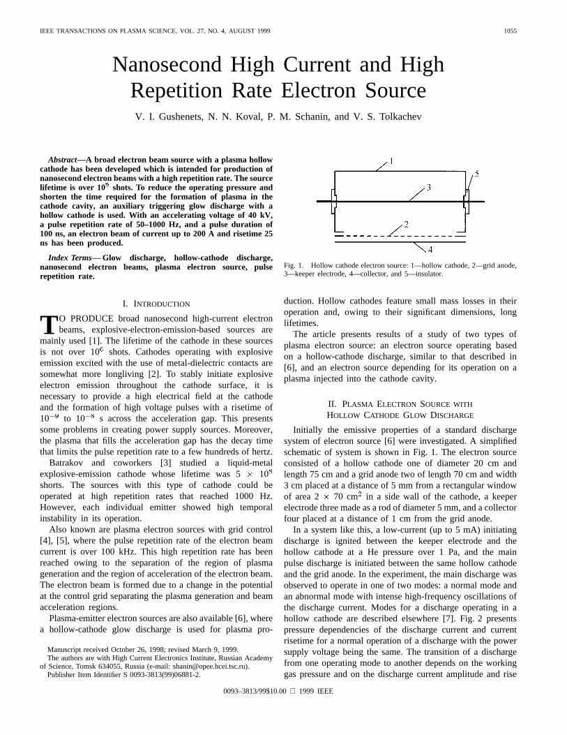
Fig. 1. Hollow cathode electron source: 1—hollow cathode, 2—grid anode,3—keeper electrode, 4—collector, and 5—insulator.
duction. Hollow cathodes feature small mass losses in theiroperation and, owing to their significant dimensions, longlifetimes.
The article presents results of a study of two types ofplasma electron source: an electron source operating basedon a hollow-cathode discharge, similar to that described in[6], and an electron source depending for its operation on aplasma injected into the cathode cavity.
II. PLASMA ELECTRON SOURCE WITH
HOLLOW CATHODE GLOW DISCHARGE
Initially the emissive properties of a standard dischargesystem of electron source [6] were investigated. A simplifiedschematic of system is shown in Fig. 1. The electron sourceconsisted of a hollow cathode one of diameter 20 cm andlength 75 cm and a grid anode two of length 70 cm and width3 cm placed at a distance of 5 mm from a rectangular windowof area 2 70 cm in a side wall of the cathode, a keeperelectrode three made as a rod of diameter 5 mm, and a collectorfour placed at a distance of 1 cm from the grid anode.
In a system like this, a low-current (up to 5 mA) initiatingdischarge is ignited between the keeper electrode and thehollow cathode at a He pressure over 1 Pa, and the mainpulse discharge is initiated between the same hollow cathodeand the grid anode. In the experiment, the main discharge wasobserved to operate in one of two modes: a normal mode andan abnormal mode with intense high-frequency oscillations ofthe discharge current. Modes for a discharge operating in ahollow cathode are described elsewhere [7]. Fig. 2 presentspressure dependencies of the discharge current and currentrisetime for a normal operation of a discharge with the powersupply voltage being the same. The transition of a dischargefrom one operating mode to another depends on the workinggas pressure and on the discharge current amplitude and rise
0093–3813/99$10.00 1999 IEEE

1056 IEEE TRANSACTIONS ON PLASMA SCIENCE, VOL. 27, NO. 4, AUGUST 1999
Fig. 2. The discharge current risetime versus pressure He.
rate. It has also been found that decreasing pressure increasesthe formation time of the discharge. The discharge currentreaches its maximum in 20s at a pressure of 3.9 Pa and in45 s at 1.4 Pa. The discharge formation time and, hence, theduration of the discharge current pulse can be decreased byproducing a substantial overvoltage across the discharge gap.On doing this, however, the current rise rate increases, and thishas the result that the discharge, as mentioned above, goesinto an abnormal operating mode with a strong modulationof the current at the rise current part of pulse. As the pulseduration is reduced or the discharge current is increased,the modulation amplitude increases and eventually the wholepulse becomes modulated by high-frequency oscillations. Inaddition, a constriction of the main discharge was observedin the experiment that was rid by using a high-current pulsedinitiating discharge instead of a low-current dc discharge. Inthe experimental study it has been established that in orderto ignite a steady-state hollow-cathode discharge in such asystem, it is necessary that the parameters of the initiatingdischarge (current amplitude and pulse duration) be at leastequal to the parameters of the main discharge or even exceedthem. The use of a high-current initiating discharge makes itpossible to shorten the current pulse of the main dischargeand, hence, the emission current pulses.
Experiments on extraction of electrons have shown that withthe accelerating voltage applied between the grid anode andthe collector equal to 17 kV the plasma cathode provided anemission current of up to 100 A at a main discharge currentof 120 A and a pressure of 2.6 Pa. The current pulse had asinusoidal waveform with the full width at half maximum 3
s. The initiating discharge parameters were as follows: thepeak current equal to 200 A and the pulse duration equal toabout 30 s.
The high gas pressure necessary for stable initiation andsteady-state operation of the main discharge and the use ofHe as a working gas constrain the utilization of this type ofdischarge as an electron source. In the experiment described in[7] the reduction of the operating pressure in a hollow-cathodeglow discharge to below 10 Pa was accomplished through
the fulfillment of the condition that the cathode area be greaterthan the anode area by a factor of , where is theion mass and is the electron mass. However, the fulfillmentof this condition results in a considerable increase in the sizeof the hollow cathode, and this is not always reasonable.
III. PLASMA ELECTRON SOURCE WITH
EXTERNAL INJECTION OF PLASMA
A. Experimental Setup
To elucidate whether it is possible to produce high-currentnanosecond electron beams in electron sources with plasmahollow cathodes, depending for their operation on a glowdischarge, we have investigated the emissive properties of anelectrode system [8] where a glow discharge was initiated atlow working gas pressures. To reduce the pressure at whicha glow discharge stably operates in the cathode cavity, anauxiliary plasma source is used whose operation is also basedon a hollow-cathode discharge. Reduction of the operatingpressure makes it possible to preclude Paschen’s breakdownin the acceleration gap.
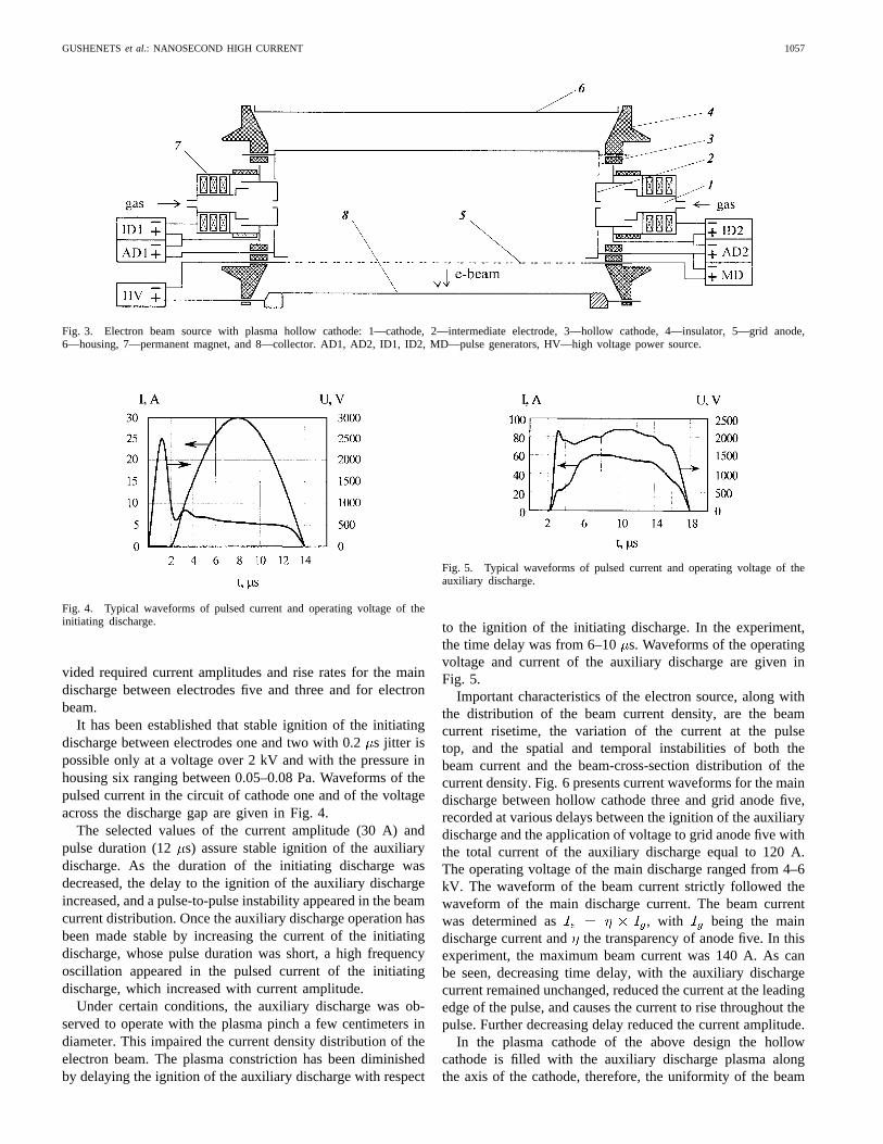
The experimental plasma electron source is shown schemat-ically in Fig. 3. Electrons are emitted from the plasma ofthe discharge initiated between main hollow cathode three ofdiameter 22 cm and grid anode five. The emission surfacearea is 2 75 cm. To reduce the operating pressure andto improve the distribution of electron beam current density,two discharge-initiating systems are used at the left and theright ends of hollow cathode. The initiating system consists ofcathode one and intermediate electrode two. The working gas(air, N ) is fed through cathode one. Cathode cavity three andinitiating cell are joint via a small hole (5 mm in diameter) inintermediate electrode. Owing to the small size of the hole, apressure drop appears between the two cavities, which favorsthe initiation of a discharge between intermediate electrodetwo and cathode one.
The source operates as follows. The initiating dischargebetween electrodes one and two is ignited first on applicationof a voltage pulse from the generator ID2. After a certain time,which has been determined experimentally, a voltage producedby the pulse generator AD2 is applied to the gap betweenintermediate electrode two and cathode three to initiate anauxiliary discharge. Thereafter, with some delay as well, avoltage produced by the nanosecond pulse generator MD isapplied to the gap between cathode three and grid anodefive. The delay of the application of voltage to anode fivedepends on the current of the auxiliary discharge. Electronsare accelerated by a dc voltage applied between anode five andcollector eight. The collector has 13 holes of diameter 0.7 cmspaced 5.4 cm. Behind the holes, 13 Faraday caps of diameter2 cm are placed to measure the emission current densitydistribution. A high-voltage rectifier (HV) with a capacitivefilter was used as a source of accelerating voltage.
B. Experimental Results
In the course of the experiment, operating modes for theinitiating and auxiliary discharges were selected which pro-
GUSHENETSet al.: NANOSECOND HIGH CURRENT 1057
Fig. 3. Electron beam source with plasma hollow cathode: 1—cathode, 2—intermediate electrode, 3—hollow cathode, 4—insulator, 5—grid anode,6—housing, 7—permanent magnet, and 8—collector. AD1, AD2, ID1, ID2, MD—pulse generators, HV—high voltage power source.
Fig. 4. Typical waveforms of pulsed current and operating voltage of theinitiating discharge.
vided required current amplitudes and rise rates for the maindischarge between electrodes five and three and for electronbeam.
It has been established that stable ignition of the initiatingdischarge between electrodes one and two with 0.2s jitter ispossible only at a voltage over 2 kV and with the pressure inhousing six ranging between 0.05–0.08 Pa. Waveforms of thepulsed current in the circuit of cathode one and of the voltageacross the discharge gap are given in Fig. 4.
The selected values of the current amplitude (30 A) andpulse duration (12 s) assure stable ignition of the auxiliarydischarge. As the duration of the initiating discharge wasdecreased, the delay to the ignition of the auxiliary dischargeincreased, and a pulse-to-pulse instability appeared in the beamcurrent distribution. Once the auxiliary discharge operation hasbeen made stable by increasing the current of the initiatingdischarge, whose pulse duration was short, a high frequencyoscillation appeared in the pulsed current of the initiatingdischarge, which increased with current amplitude.
Under certain conditions, the auxiliary discharge was ob-served to operate with the plasma pinch a few centimeters indiameter. This impaired the current density distribution of theelectron beam. The plasma constriction has been diminishedby delaying the ignition of the auxiliary discharge with respect
Fig. 5. Typical waveforms of pulsed current and operating voltage of theauxiliary discharge.
to the ignition of the initiating discharge. In the experiment,the time delay was from 6–10s. Waveforms of the operatingvoltage and current of the auxiliary discharge are given inFig. 5.
Important characteristics of the electron source, along withthe distribution of the beam current density, are the beamcurrent risetime, the variation of the current at the pulsetop, and the spatial and temporal instabilities of both thebeam current and the beam-cross-section distribution of thecurrent density. Fig. 6 presents current waveforms for the maindischarge between hollow cathode three and grid anode five,recorded at various delays between the ignition of the auxiliarydischarge and the application of voltage to grid anode five withthe total current of the auxiliary discharge equal to 120 A.The operating voltage of the main discharge ranged from 4–6kV. The waveform of the beam current strictly followed thewaveform of the main discharge current. The beam currentwas determined as , with being the maindischarge current and the transparency of anode five. In thisexperiment, the maximum beam current was 140 A. As canbe seen, decreasing time delay, with the auxiliary dischargecurrent remained unchanged, reduced the current at the leadingedge of the pulse, and causes the current to rise throughout thepulse. Further decreasing delay reduced the current amplitude.
In the plasma cathode of the above design the hollowcathode is filled with the auxiliary discharge plasma alongthe axis of the cathode, therefore, the uniformity of the beam

1058 IEEE TRANSACTIONS ON PLASMA SCIENCE, VOL. 27, NO. 4, AUGUST 1999
Fig. 6. Typical waveforms of pulsed current in the main discharge fordifferent delay. 1–10�s, 2–6�s.
Fig. 7. Distribution of electron beam current density.
current density distribution in the longitudinal direction waswithin 15%. The varied-transparency grid used in the anodehas made it possible to improve the current density distributionand makes it uniform within 8% (Fig. 7).
With the above discharge currents and voltages, the totalpower demand of the plasma cathode at a frequency of 1000Hz was 2 kW. This gave rise to some difficulties with the heatremoval from the source electrodes being at a high potential.To reduce the power demand, the polarity of the voltage atthe electrodes of the initiating and auxiliary discharges waschanged. As a result, the operating voltage of the auxiliarydischarge decreased to 1 kV. As to preliminary filling ofthe hollow cathode with plasma, it turned out sufficient touse only one initiating discharge and one auxiliary discharge.Despite the need to double the initiating discharge current,the reduction of the number of discharges and the decrease inthe operating voltage of the auxiliary discharge have made itpossible to reduce the power demand for the plasma cathodealmost to one third of its initial value. Moreover, this hadthe results that the beam current was increased to 200 Aand the distribution of the beam current density was madeuniform within 7.5% not using a varied-transparency grid inthe anode. For the experimental electron source, the beamcurrent and electron energy were limited by the power of thenanosecond generator providing power supply for the maindischarge and by the maximum voltage of the power sourcefor the acceleration gap.
IV. CONCLUSIONS
The study performed has demonstrated that the glowdischarge can successfully be used in high-current electronsources operating with high pulse repetition rates.
1) Preliminary filling of the hollow cathode with the aux-iliary discharge plasma allows one to eliminate theproblems involved in the formation of pulsed electronbeams with high current rise rates at low pressuresand the problems associated with Paschen’s breakdown,which may occur in long accelerating gaps, and obviatesthe necessity to use helium as the working gas.
2) Owing to the separation of the plasma generation regionfrom the electron beam acceleration region, the pulserepetition rate is not limited by the plasma decay time,as this is the case in explosive-emission-cathode sources.
3) The change of the arc discharge for the glow discharge inthe plasma cathode allows one to increase significantlythe lifetimes for the cathode and provide a uniformdistribution of the beam current density by the simplestway.
4) Controlling the current rise rate and pulse duration ofthe electron beam by proper formation of the dischargeat low operating voltages makes it possible to use inpulsed electron sources either a dc accelerating voltageor a pulsed slowly rising voltage.
REFERENCES
[1] S. P. Bugaev, Yu. E. Kreindel, and P. M. Schanin,Large-Cross-Section Electron Beams(in Russian). Moscow, Russia: Energoatomiz-dat, 1984.
[2] F. Ya. Zagulov, S. D. Korovin, O. P. Kutenkov,et al., BulletenIzobretenii,Certificate 1579321, 1990.
[3] A. V. Batrakov, S. A. Popov, and D. I. Proskurovsky, inProc. XVIIthInt. Symp. Discharges Electr. Insulation Vacuum,Berkeley, CA, 1996,vol. 2, p. 579.
[4] V. I. Gushenets, N. N. Koval, and P. M. Schanin, inProc. 8th Int. Conf.High-Power Particle Beams (Beams’90),Novosibirsk, Russia, 1990, vol.2, pp. 886–891.
[5] S. P. Bugaev, V. I. Gushenets, and P. M. Schanin, inProc. 9th Int.Conf. High-Power Particle Beams (Beams’92),Washington, DC, 1992,vol. 2, pp. 1099–1104.
[6] J. R. Bayless, “The plasma-cathode electron gun,”Rev. Sci. Instrum.,vol. 46, no. 9, pp. 1158–1160, 1975.
[7] A. S. Metel, “Peculiarities of formation quasistationary high currenthollow-cathode glow discharge at low gas pressures,”Zh. Tekh. Fiz.,vol. 56, no. 12, pp. 2239–2339, 1986.
[8] E. M. Oks, A. V. Vizir, and G. Yu. Yushkov, “Low-pressure hollow-cathode glow discharge for broad beam gaseous ion source,”Rev. Sci.Instrum.,vol. 69, no. 2, pp. 853–855, 1998.
V. I. Gushenetsreceived the M.S. degree in elec-tronics from Tomsk State University of ControlSystems and Radioelectronics, Russia, in 1978 andthe Ph.D. degree from the High Current ElectronicsInstitute, Tomsk, in 1991.
Since 1978, he has worked for the High Cur-rent Electronics Institute and is currently a SeniorPhysicist. His research involves the developmentof plasma electron sources and accelerators, pulsepower generators, and power sources for electronand ion guns. His current interests include genera-
tion of nanosecond electron beams from plasma of gas discharge. He is theco-author of more than 30 research papers.

GUSHENETSet al.: NANOSECOND HIGH CURRENT 1059
N. N. Koval graduated in 1971 from TomskPolytechnical University, Russia, as an Engineer-Physicist in physical electronics.
From 1971 to 1975, he worked as a member ofthe teaching staff at the Polytechnical University.Since 1975, he has been with the High CurrentElectronics Institute, Tomsk. His area of scientificinterests include the study of vacuum and gasdischarges, the development of electron, ion, andplasma sources, and technological applications ofcharged-particle beams and plasmas. At present, he
heads a team of researchers at the Laboratory of Plasma Emission Electronics.He is a co-author of more than 50 scientific articles.
P. M. Schaninreceived the M.S. degree in physics from Tomsk PolytechnicalUniversity, Russia, in 1956, the Ph.D. degree from Polytechnical Universityin 1962, and the degree of Physical and Mathematical Sciences from the HighCurrent Electronics Institute, Tomsk, in 1986.
Since 1977, he has been working at the High Current Electronics Instituteas Head of Laboratory. His main interests are in investigations of vacuum andgas discharges, emission of charge particles from plasma, and application ofelectrons and ions for surface modification.
V. S. Tolkachev graduated from Tomsk State Uni-versity of Control Systems and Radioelectronics,Russia, in 1972. He received the Ph.D. degree in1988 from the Institute of High Current Electronics.
Since 1977, he has been with the High CurrentElectronics Institute. His scientific interests includethe development and creation of electron, ion, andplasma sources for research and technological appli-cations. Presently, he works as a Senior Researcher.He is a coauthor of more than 20 scientific articles.