nanomechanicsofnonidealsingle-and double …downloads.hindawi.com/journals/jnm/2012/490872.pdf ·...
TRANSCRIPT
Hindawi Publishing CorporationJournal of NanomaterialsVolume 2012, Article ID 490872, 9 pagesdoi:10.1155/2012/490872
Research Article
Nanomechanics of Nonideal Single- andDouble-Walled Carbon Nanotubes
C. H. Wong and V. Vijayaraghavan
School of Mechanical and Aerospace Engineering, Nanyang Technological University, 50 Nanyang Avenue, Singapore 639798
Correspondence should be addressed to C. H. Wong, [email protected]
Received 24 March 2012; Accepted 12 June 2012
Academic Editor: Leonard Deepak Francis
Copyright © 2012 C. H. Wong and V. Vijayaraghavan. This is an open access article distributed under the Creative CommonsAttribution License, which permits unrestricted use, distribution, and reproduction in any medium, provided the original work isproperly cited.
The buckling characteristics of nonideal single- and double-walled carbon nanotubes were studied in this work via moleculardynamics simulation method. An imperfectly straight nonideal single-walled carbon nanotube (SWCNT) with a bent along thetube axis was used to form an array which is subjected to compression. The change in orientation of bends will result in a variationof nonbonded interactions in an SWCNT array system. We find that these variations in the nonbonded interactions strongly affectthe buckling resistance of the SWCNT array. Similarly, a nonideal double-walled carbon nanotube (DWCNT) is constructed byvarying the interlayer distance by introducing a center offset on the inner core SWCNT. The inclusion of offset along the tubeaxis in such nonideal DWCNT can enhance or deteriorate the mechanical qualities of the DWCNT under compression. Ournumerical studies on nonideal CNT systems suggest a possibility of designing high-performing CNTs for applications involvingfiber reinforcements.
1. Introduction
Carbon nanotubes (CNTs) have attracted a significantresearch interest in the academic and industry circles dueto its remarkable characteristics [1]. Extensive applicationof CNTs has been in the field of structural engineeringdue to its high tensile strength [2–4]. Most investigationson the mechanical characteristics of CNTs have been per-formed theoretically by deploying continuum mechanics ormolecular dynamics (MD) simulation technique. The releasein strain energy of CNTs subjected to large deformationshas been explained by making use of a continuum shellmodel proposed by Yacobson et al. [5]. The variation of thebuckling load with the CNT diameter has been analyzed byLiew et al. [6]. The REBO potential was further modifiedto include the long-range effects to study the effect of vander Waal forces on the compressive strength of CNT by Cheet al. [7]. Ru [8] developed an elastic double-shell mod-el to describe the infinitesimal buckling of a double-walled carbon nanotube (DWCNT). A systematic analysison the buckling of multiwalled CNT (MWCNT) under rad-ial pressure was investigated by Wang et al. [9]. They
introduced an approximate method to replace MWCNT byfew layered elastic shell. The effect of boundary conditionson the buckling behavior of MWCNTs has been studied byTong et al. [10]. They found that clamping the outermostCNT in an MWCNT can enhance the critical strain up tofour times the original value. The buckling of DWCNTs sub-jected to torsion or compression has been studied by Lu etal. [11]. They developed a continuum model to account forthe van der Waals interactions that act in between the layersof the DWCNT. The effect of tube radius on the criticalbuckling load of a MWCNT has been investigated by Heet al. [12]. They derived explicit formulas to describe theinterlayer van der Waals interaction in an MWCNT. Amolecular structural mechanics approach was utilized toexplain the elastic buckling behavior of carbon nanotubesby Li and Chou [13]. The results from this study indicatethe improvement in the critical axial compressive loadof a double-walled CNT (DWCNT) to that of a single-walled CNT (SWCNT). Though all the previously mentionedstudies suggest superior mechanical qualities of CNTs, theobserved mechanical strengths [14, 15] are always lower thanthe theoretical predictions. This observation is attributed

2 Journal of Nanomaterials
mainly due to the poor load transfer in between the layersof the MWCNT [16] and those of the interspatial layersin a CNT bundle [14]. We further need to note that thefabricated CNTs [17] are seldom perfectly straight in thelaboratory conditions resulting in its nonideal nature. Theeffect of these curvatures on the elastic properties of CNTswith large aspect ratio can never be ignored [18]. In the firstpart of our present study, we report the elastic propertiesof a nonideal SWCNT array comprising long imperfectlystraight SWCNTs [18] with a single bent along the tubeaxis. We find that the buckling characteristics are stronglyaffected by the interspatial distance of the SWCNT array dueto the variations in arranging a bent orientation. Based onthis understanding, we define a nonideal DWCNT in whichthe center core SWCNT is arranged at an offset distance tothe outer SWCNT. MD simulation technique is employedto investigate the buckling characteristics of the nonidealDWCNT. The results clearly indicate that the resistance tobuckling in a DWCNT arises mainly from the interlayervan der Waals interactions which are strongly influenced bythe interlayer spacing. It should further be noted that closespacing of the adjacent CNT layers in a nonideal MWCNTintroduces cross-links [19] which enhance the interwall shearstrength. Liew et al. [20] performed buckling analysis ofabnormal MWCNT by deploying a multishell continuummodel with a refined van der Waal force model. Their inves-tigations revealed that the effect of the van der Waals inter-action is more significant for abnormal MWCNT than fornormal MWCNT. Additionally, Song et al. [21] performednumerical simulation analysis to investigate the torsion-al responses of an abnormal MWCNT. They found thatthe critical torsional moments of DWCNTs are considerablyenhanced due to the abnormal interlayer spacing of theCNT. Their results were significant due to the fact thatthe critical torsional moment does not always increasewith decrease in the interlayer distance of DWCNTs. Zhanget al. [22] proposed a computer simulation model of novelDWCNTs with an interlayer distance of less than 3.4 A withimproved compressive stability. The MD studies on DWC-NTs with abnormal interlayer distances by Song and Zhi[23] further confirmed that the small interlayer spacing pro-vides an effective channel for load transfer of outer and innertubes and permits mechanical participation of two walls.Therefore, an optimum design of the interlayer spacing ina DWCNT will result in a superior mechanical performance.We would however like to remark that the current study aimsto propose only a numerical model of nonideal DWCNT, andits fabrication method still needs to be investigated. The fol-lowing section presents the computational model employedin our current work. The studies on the compressivecharacteristics of SWCNT array are described next followedby our research on the DWCNT. Finally we summarized ourfindings in the conclusion section.
2. Numerical Simulation and Model
In the current study, the interatomic forces that act inbetween the covalently bonded carbon atoms of the CNTwere computed using the Brenner’s second generation
reactive empirical bond order function [25]. The long rangeLennard-Jones 12–6 potential [26] is further deployed toaccount for the non-bonded interactions in an SWCNT arrayand the DWCNT. The mathematical representation of thepreviously mentioned potentials is given as
EREBO = VR
(ri j)− bi jVA
(ri j)
, (1)
where the repulsive and attractive pair terms are given byVR and VA, respectively. The bi j term is used to include thereactive empirical bond order between the atoms. And theLennard-Jones (12–6) potential is given as
ELJ = 4ε
⎡⎣(σ
ri j
)12
−(σ
ri j
)6⎤⎦, (2)
where ε = 4.55 meV which is the well depth parameter andσ = 3.4 A is the collision diameter between two atoms [27].
The complete form of the potential employed is thereforegiven by
ECNT = EREBO + EvdW. (3)
The contribution due to the van der Waals interaction(EvdW) is accounted for when the covalent potential given byEREBO becomes zero for bond lengths exceeding 2.0 A. EvdW
is therefore defined as [28]
EvdW
=
⎧⎪⎪⎪⎨⎪⎪⎪⎩
0, ri j≤2.0 A,
c3,k
(ri j − rk
)3+ c2,k
(ri j − rk
)2, 2.0 A < ri j≤3.2 A,
ELJ
(ri j)
, 3.2 A < ri j≤10.0 A,
(4)
where cn,k are the cubic spline coefficients for computation ofthe potential [28] when it turns repulsive when 2.0 A < ri j ≤3.2 A.
The mechanical properties of the nonideal SWCNTand DWCNT were investigated using MD simulation. Thesimulation procedure consists of defining the initial positionsof atoms after which it is subjected to relaxation using thepotential model represented above to obtain the relaxedenergy positions using conjugate gradient technique in anNVE ensemble. The carbon atoms at both ends of the systemare fixed not to move in the plane normal to the tube axisand subjected to a finite inward displacement. The remainingatoms are subjected to relaxation after every 1000 time stepswhere the data is extracted. The procedure is repeated untilthe system buckles completely. This simulation consists of atotal of 200,000 time steps with each time step equivalent to1 fs.
3. Studies on SWCNT Array
3.1. Description of the Array System. It is evident from ourprevious study [18] that the critical compressive strain in anonideal imperfectly straight SWCNT will depend strongly
Journal of Nanomaterials 3
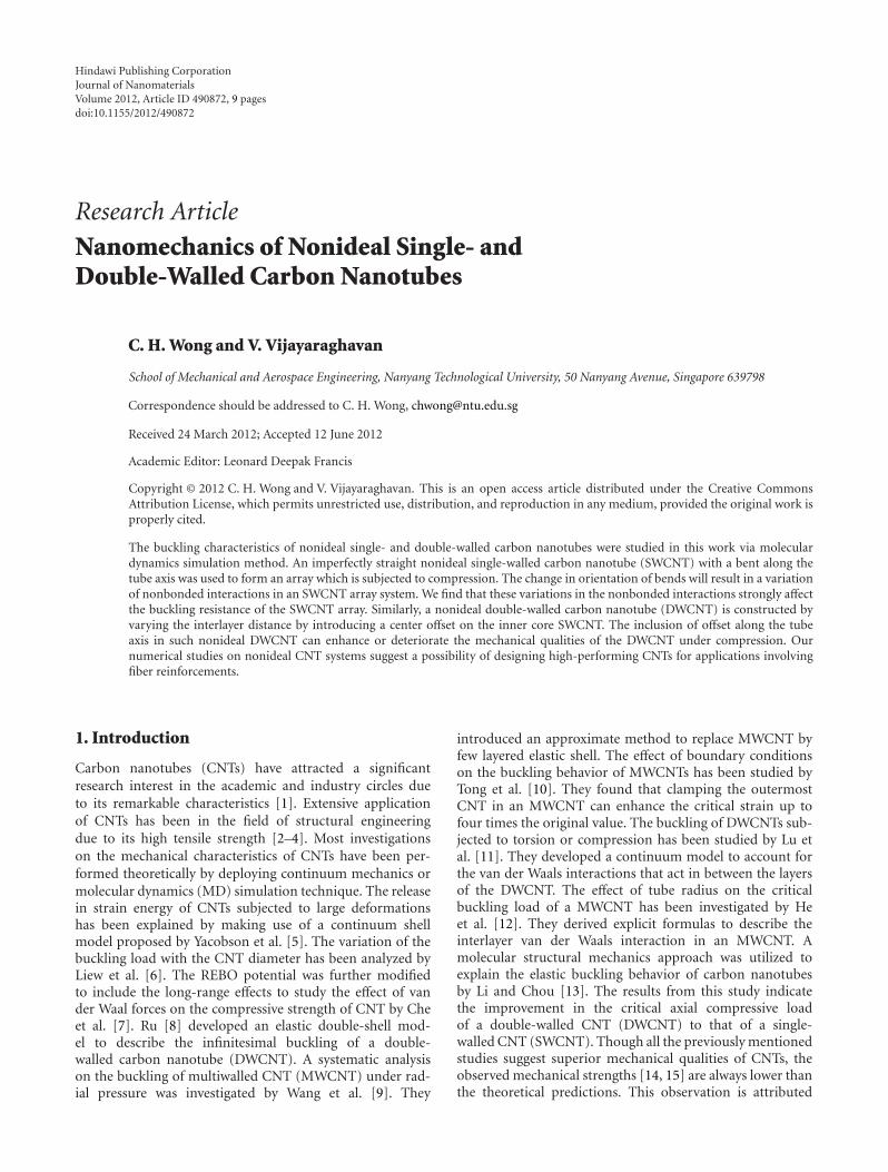
(a)
(b)
Figure 1: System of two “C” shaped CNTs arranged to form (a) aconvex array and (b) a concave array.
0
0.02
0.04
0.06
0.08
0.1
0 5 10 15 20 25
Com
pres
sive
str
ain
Length of SWCNT (nm)
Perfectly straight SWCNT
“C” shaped SWCNTReference [24]
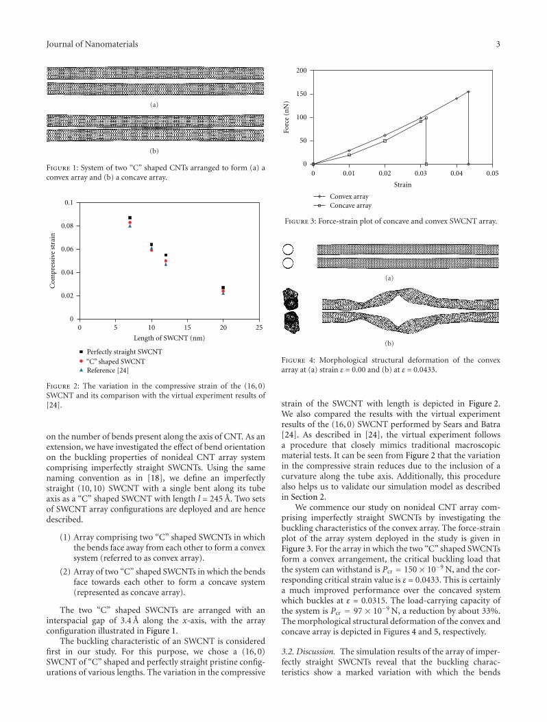
Figure 2: The variation in the compressive strain of the (16, 0)SWCNT and its comparison with the virtual experiment results of[24].
on the number of bends present along the axis of CNT. As anextension, we have investigated the effect of bend orientationon the buckling properties of nonideal CNT array systemcomprising imperfectly straight SWCNTs. Using the samenaming convention as in [18], we define an imperfectlystraight (10, 10) SWCNT with a single bent along its tubeaxis as a “C” shaped SWCNT with length l = 245 A. Two setsof SWCNT array configurations are deployed and are hencedescribed.
(1) Array comprising two “C” shaped SWCNTs in whichthe bends face away from each other to form a convexsystem (referred to as convex array).
(2) Array of two “C” shaped SWCNTs in which the bendsface towards each other to form a concave system(represented as concave array).
The two “C” shaped SWCNTs are arranged with aninterspacial gap of 3.4 A along the x-axis, with the arrayconfiguration illustrated in Figure 1.
The buckling characteristic of an SWCNT is consideredfirst in our study. For this purpose, we chose a (16, 0)SWCNT of “C” shaped and perfectly straight pristine config-urations of various lengths. The variation in the compressive
0
50
100
150
200
0 0.01 0.02 0.03 0.04 0.05
Forc
e (n
N)
Strain
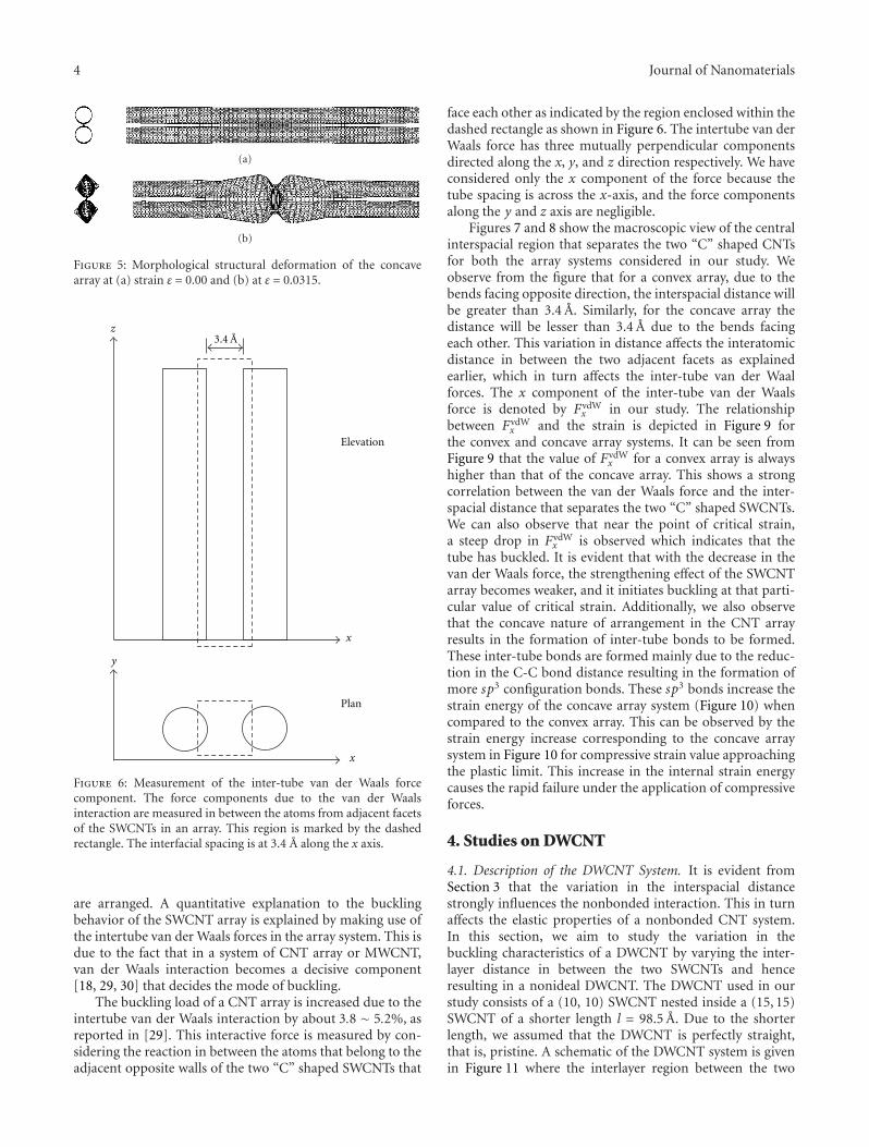
Convex arrayConcave array
Figure 3: Force-strain plot of concave and convex SWCNT array.
(a)
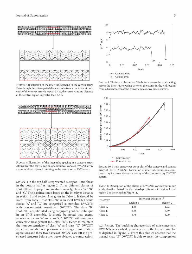
(b)
Figure 4: Morphological structural deformation of the convexarray at (a) strain ε = 0.00 and (b) at ε = 0.0433.
strain of the SWCNT with length is depicted in Figure 2.We also compared the results with the virtual experimentresults of the (16, 0) SWCNT performed by Sears and Batra[24]. As described in [24], the virtual experiment followsa procedure that closely mimics traditional macroscopicmaterial tests. It can be seen from Figure 2 that the variationin the compressive strain reduces due to the inclusion of acurvature along the tube axis. Additionally, this procedurealso helps us to validate our simulation model as describedin Section 2.
We commence our study on nonideal CNT array com-prising imperfectly straight SWCNTs by investigating thebuckling characteristics of the convex array. The force-strainplot of the array system deployed in the study is given inFigure 3. For the array in which the two “C” shaped SWCNTsform a convex arrangement, the critical buckling load thatthe system can withstand is Pcr = 150× 10−9 N, and the cor-responding critical strain value is ε = 0.0433. This is certainlya much improved performance over the concaved systemwhich buckles at ε = 0.0315. The load-carrying capacity ofthe system is Pcr = 97 × 10−9 N, a reduction by about 33%.The morphological structural deformation of the convex andconcave array is depicted in Figures 4 and 5, respectively.
3.2. Discussion. The simulation results of the array of imper-fectly straight SWCNTs reveal that the buckling charac-teristics show a marked variation with which the bends
4 Journal of Nanomaterials
(a)
(b)
Figure 5: Morphological structural deformation of the concavearray at (a) strain ε = 0.00 and (b) at ε = 0.0315.
z
x
y
x
Elevation
Plan
3.4 A
Figure 6: Measurement of the inter-tube van der Waals forcecomponent. The force components due to the van der Waalsinteraction are measured in between the atoms from adjacent facetsof the SWCNTs in an array. This region is marked by the dashedrectangle. The interfacial spacing is at 3.4 A along the x axis.
are arranged. A quantitative explanation to the bucklingbehavior of the SWCNT array is explained by making use ofthe intertube van der Waals forces in the array system. This isdue to the fact that in a system of CNT array or MWCNT,van der Waals interaction becomes a decisive component[18, 29, 30] that decides the mode of buckling.
The buckling load of a CNT array is increased due to theintertube van der Waals interaction by about 3.8 ∼ 5.2%, asreported in [29]. This interactive force is measured by con-sidering the reaction in between the atoms that belong to theadjacent opposite walls of the two “C” shaped SWCNTs that
face each other as indicated by the region enclosed within thedashed rectangle as shown in Figure 6. The intertube van derWaals force has three mutually perpendicular componentsdirected along the x, y, and z direction respectively. We haveconsidered only the x component of the force because thetube spacing is across the x-axis, and the force componentsalong the y and z axis are negligible.
Figures 7 and 8 show the macroscopic view of the centralinterspacial region that separates the two “C” shaped CNTsfor both the array systems considered in our study. Weobserve from the figure that for a convex array, due to thebends facing opposite direction, the interspacial distance willbe greater than 3.4 A. Similarly, for the concave array thedistance will be lesser than 3.4 A due to the bends facingeach other. This variation in distance affects the interatomicdistance in between the two adjacent facets as explainedearlier, which in turn affects the inter-tube van der Waalforces. The x component of the inter-tube van der Waalsforce is denoted by FvdW
x in our study. The relationshipbetween FvdW
x and the strain is depicted in Figure 9 forthe convex and concave array systems. It can be seen fromFigure 9 that the value of FvdW
x for a convex array is alwayshigher than that of the concave array. This shows a strongcorrelation between the van der Waals force and the inter-spacial distance that separates the two “C” shaped SWCNTs.We can also observe that near the point of critical strain,a steep drop in FvdW
x is observed which indicates that thetube has buckled. It is evident that with the decrease in thevan der Waals force, the strengthening effect of the SWCNTarray becomes weaker, and it initiates buckling at that parti-cular value of critical strain. Additionally, we also observethat the concave nature of arrangement in the CNT arrayresults in the formation of inter-tube bonds to be formed.These inter-tube bonds are formed mainly due to the reduc-tion in the C-C bond distance resulting in the formation ofmore sp3 configuration bonds. These sp3 bonds increase thestrain energy of the concave array system (Figure 10) whencompared to the convex array. This can be observed by thestrain energy increase corresponding to the concave arraysystem in Figure 10 for compressive strain value approachingthe plastic limit. This increase in the internal strain energycauses the rapid failure under the application of compressiveforces.
4. Studies on DWCNT
4.1. Description of the DWCNT System. It is evident fromSection 3 that the variation in the interspacial distancestrongly influences the nonbonded interaction. This in turnaffects the elastic properties of a nonbonded CNT system.In this section, we aim to study the variation in thebuckling characteristics of a DWCNT by varying the inter-layer distance in between the two SWCNTs and henceresulting in a nonideal DWCNT. The DWCNT used in ourstudy consists of a (10, 10) SWCNT nested inside a (15, 15)SWCNT of a shorter length l = 98.5 A. Due to the shorterlength, we assumed that the DWCNT is perfectly straight,that is, pristine. A schematic of the DWCNT system is givenin Figure 11 where the interlayer region between the two
Journal of Nanomaterials 5
Figure 7: Illustration of the inter-tube spacing in the convex array.Even though the inter-spatial distance in between the tubes at bothends of the convex array is kept at 3.4 A, the corresponding distanceat the central region is greater than 3.4 A.
Figure 8: Illustration of the inter-tube spacing in a concave array.Atoms near the central region of a nonideal concave SWCNT arrayare more closely spaced resulting in the formation of C-C bonds.
SWCNTs in the top half is represented as region 1 and thosein the bottom half as region 2. Three different classes ofDWCNTs are deployed in our study, namely, classes “A,” “B”and “C.” The classification is based on the interlayer distancein region 1 and region 2 as given in Table 1. It should benoted from Table 1 that class “B” is an ideal DWCNT whileclasses “A” and “C” are categorized as nonideal DWCNTswith nonconcentric constituent SWCNTs. The class “B”DWCNT is equilibrated using conjugate gradient techniquein an NVE ensemble. It should be noted that energyrelaxation of class “A” and class “C” DWCNT will result in aconcentric arrangement (i.e., class “B”). Hence to maintainthe non-concentricity of class “A” and class “C” DWCNTstructure, we did not perform any energy minimizationoperations and these two classes of DWCNTs are left as a pre-stressed structure before they were subjected to compression.
0
2
4
6
8
10
0 0.01 0.02 0.03 0.04 0.05
Strain
Concave arrayConvex array
Fvd
Wx
(nN
)
Figure 9: The inter-tube van der Waals force versus the strain actingacross the inter-tube spacing between the atoms in the x-directionfrom adjacent facets of the convex and concave array systems.
0
0.01
0.02
0.03
0.04
0.05
0.06
0.07
0.08
0 0.01 0.02 0.03 0.04 0.05
Strain
Convex arrayConcave array
Stra
in e
ner
gy p
er a
tom
(eV
/ato
m)
Figure 10: Strain energy per atom plot of the concave and convexarray of (10, 10) SWCNT. Formation of inter-tube bonds in a con-cave array increases the strain energy of the concave array SWCNTsystem.
Table 1: Description of the classes of DWCNTs considered in ourstudy classified based on the inter-layer distance in region 1 andregion 2 as described in Figure 11.
DWCNTInterlayer Distance (A)
Region 1 Region 2
Class A 4.86 1.92
Class B 3.38 3.39
Class C 3.78 3.00
4.2. Results. The buckling characteristic of non-concentricDWCNTs is described by making use of the force-strain plotas depicted in Figure 12. From this plot we observe that thenormal class “B” DWCNT is able to resist the compression
6 Journal of Nanomaterials
Region 1
Region 2x axis
z axis
x axis
y axis
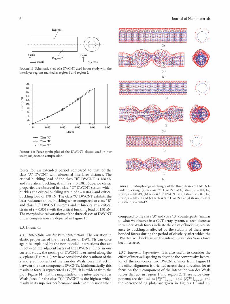
Figure 11: Schematic view of a DWCNT used in our study with theinterlayer regions marked as region 1 and region 2.
020406080
100120140160180200
0 0.01 0.02 0.03 0.04 0.05
Forc
e (n
N)
Strain
Class “A”Class “B”Class “C”
Figure 12: Force-strain plot of the DWCNT classes used in ourstudy subjected to compression.
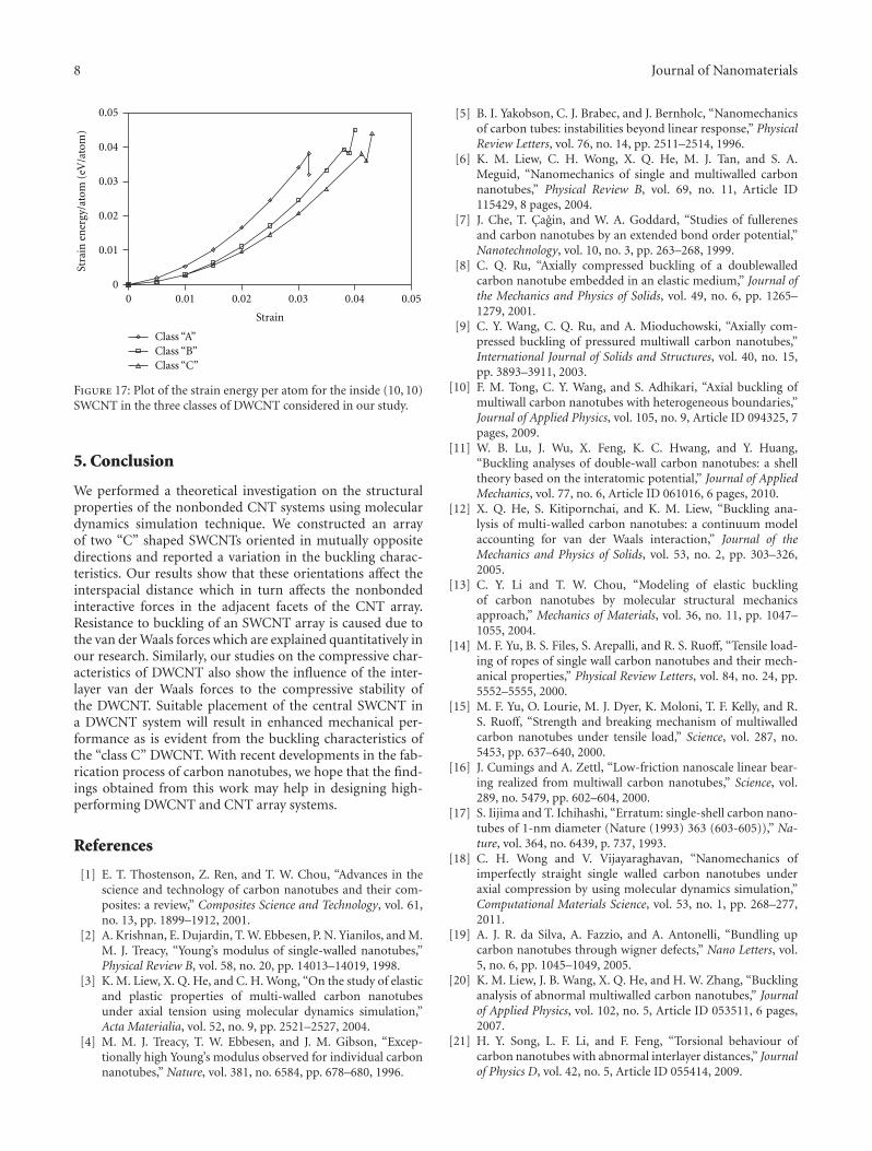
forces for an extended period compared to that of theclass “A” DWCNT with abnormal interlayer distance. Thecritical buckling load of the class “B” DWCNT is 168 nNand its critical buckling strain is ε = 0.0381. Superior elasticproperties are observed in a class “C” DWCNT system whichbuckles at a critical buckling strain of ε = 0.0412 and criticalbuckling load of 178 nN. The class “A” DWCNT exhibits theleast resistance to the buckling when compared to class “B”and class “C” DWCNT systems and it buckles at a criticalstrain of ε = 0.0319 with the critical buckling load of 130 nN.The morphological variations of the three classes of DWCNTunder compression are depicted in Figure 13.
4.3. Discussion
4.3.1. Inter-Tube van der Waals Interaction. The variation inelastic properties of the three classes of DWCNTs can onceagain be explained by the non-bonded interactions that actin between the adjacent layers of the DWCNT. Since in ourcurrent study, the nesting of DWCNT is oriented along thex-y plane (Figure 11), we have considered the resultant of thex and y components of the van der Waals force that act inbetween the two component SWCNTs. Mathematically thisresultant force is represented as FvdW
xy . It is evident from theplot (Figure 14) that the magnitude of the inter-tube van derWaals force for the class “C” DWCNT is the highest whichresults in its superior performance under compression when
(i)
(ii)
(a)
(i)
(ii)
(b)
(i)
(ii)
(c)
Figure 13: Morphological changes of the three classes of DWCNTsunder buckling. (a) A class “A” DWCNT at (i) strain, ε = 0.0, (ii)strain, ε = 0.0319, (b) A class “B” DWCNT at (i) strain, ε = 0.0, (ii)strain, ε = 0.0381 and (c) A class “C” DWCNT at (i) strain, ε = 0.0,(ii) strain, ε = 0.0412.
compared to the class “A” and class “B” counterparts. Similarto what we observe in a CNT array system, a steep decreasein van der Waals forces indicate the onset of buckling. Resist-ance to buckling is affected by the stability of these non-bonded forces during the period of elasticity after which theDWCNT will buckle when the inter-tube van der Waals forcebecomes zero.
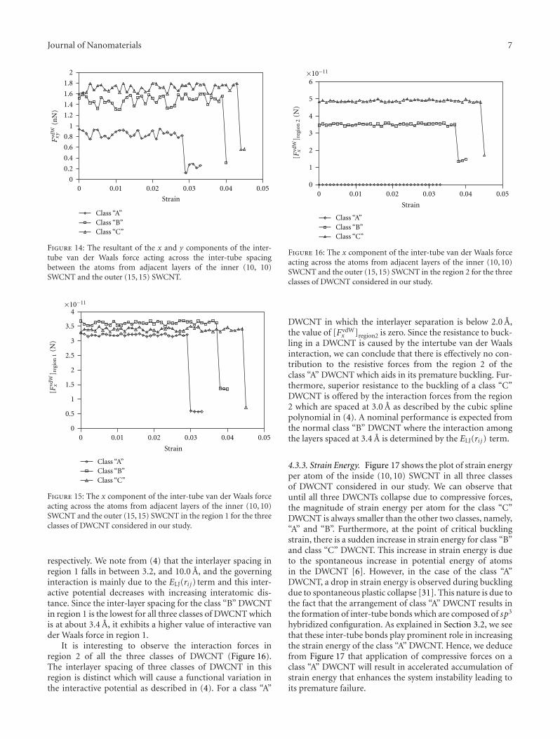
4.3.2. Interwall Separation. It is also useful to consider theeffect of interwall spacing to describe the compressive behav-ior of the non-concentric DWCNTs. Since from Figure 11the offset alignment is oriented across the x direction, let usfocus on the x component of the inter-tube van der Waalsforces that act in region 1 and region 2. These force com-ponents are denoted as [FvdW
x ]region1 and [FvdWx ]region2, and
the corresponding plots are given in Figures 15 and 16,
Journal of Nanomaterials 7
0
0.2
0.4
0.6
0.8
1
1.2
1.4
1.6
1.8
2
0 0.01 0.02 0.03 0.04 0.05
Strain
Class “A”Class “B”Class “C”
Fvd
Wxy
(nN
)
Figure 14: The resultant of the x and y components of the inter-tube van der Waals force acting across the inter-tube spacingbetween the atoms from adjacent layers of the inner (10, 10)SWCNT and the outer (15, 15) SWCNT.
Class “A”Class “B”Class “C”
0
0.5
1
1.5
2
2.5
3
3.5
4
0 0.01 0.02 0.03 0.04 0.05
Strain
×10−11
[Fvd
Wx
] reg
ion
1(N
)
Figure 15: The x component of the inter-tube van der Waals forceacting across the atoms from adjacent layers of the inner (10, 10)SWCNT and the outer (15, 15) SWCNT in the region 1 for the threeclasses of DWCNT considered in our study.
respectively. We note from (4) that the interlayer spacing inregion 1 falls in between 3.2, and 10.0 A, and the governinginteraction is mainly due to the ELJ(ri j) term and this inter-active potential decreases with increasing interatomic dis-tance. Since the inter-layer spacing for the class “B” DWCNTin region 1 is the lowest for all three classes of DWCNT whichis at about 3.4 A, it exhibits a higher value of interactive vander Waals force in region 1.
It is interesting to observe the interaction forces inregion 2 of all the three classes of DWCNT (Figure 16).The interlayer spacing of three classes of DWCNT in thisregion is distinct which will cause a functional variation inthe interactive potential as described in (4). For a class “A”
×10−11
0
1
2
3
4
5
6
0 0.01 0.02 0.03 0.04 0.05
Strain
Class “A”Class “B”Class “C”
[Fvd
Wx
] reg
ion
2(N
)
Figure 16: The x component of the inter-tube van der Waals forceacting across the atoms from adjacent layers of the inner (10, 10)SWCNT and the outer (15, 15) SWCNT in the region 2 for the threeclasses of DWCNT considered in our study.
DWCNT in which the interlayer separation is below 2.0 A,the value of [FvdW
x ]region2 is zero. Since the resistance to buck-ling in a DWCNT is caused by the intertube van der Waalsinteraction, we can conclude that there is effectively no con-tribution to the resistive forces from the region 2 of theclass “A” DWCNT which aids in its premature buckling. Fur-thermore, superior resistance to the buckling of a class “C”DWCNT is offered by the interaction forces from the region2 which are spaced at 3.0 A as described by the cubic splinepolynomial in (4). A nominal performance is expected fromthe normal class “B” DWCNT where the interaction amongthe layers spaced at 3.4 A is determined by the ELJ(ri j) term.
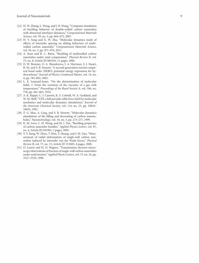
4.3.3. Strain Energy. Figure 17 shows the plot of strain energyper atom of the inside (10, 10) SWCNT in all three classesof DWCNT considered in our study. We can observe thatuntil all three DWCNTs collapse due to compressive forces,the magnitude of strain energy per atom for the class “C”DWCNT is always smaller than the other two classes, namely,“A” and “B”. Furthermore, at the point of critical bucklingstrain, there is a sudden increase in strain energy for class “B”and class “C” DWCNT. This increase in strain energy is dueto the spontaneous increase in potential energy of atomsin the DWCNT [6]. However, in the case of the class “A”DWCNT, a drop in strain energy is observed during bucklingdue to spontaneous plastic collapse [31]. This nature is due tothe fact that the arrangement of class “A” DWCNT results inthe formation of inter-tube bonds which are composed of sp3
hybridized configuration. As explained in Section 3.2, we seethat these inter-tube bonds play prominent role in increasingthe strain energy of the class “A” DWCNT. Hence, we deducefrom Figure 17 that application of compressive forces on aclass “A” DWCNT will result in accelerated accumulation ofstrain energy that enhances the system instability leading toits premature failure.
8 Journal of Nanomaterials
Class “A”Class “B”Class “C”
0
0.01
0.02
0.03
0.04
0.05
0 0.01 0.02 0.03 0.04 0.05
Strain
Stra
in e
ner
gy/a
tom
(eV
/ato
m)
Figure 17: Plot of the strain energy per atom for the inside (10, 10)SWCNT in the three classes of DWCNT considered in our study.
5. Conclusion
We performed a theoretical investigation on the structuralproperties of the nonbonded CNT systems using moleculardynamics simulation technique. We constructed an arrayof two “C” shaped SWCNTs oriented in mutually oppositedirections and reported a variation in the buckling charac-teristics. Our results show that these orientations affect theinterspacial distance which in turn affects the nonbondedinteractive forces in the adjacent facets of the CNT array.Resistance to buckling of an SWCNT array is caused due tothe van der Waals forces which are explained quantitatively inour research. Similarly, our studies on the compressive char-acteristics of DWCNT also show the influence of the inter-layer van der Waals forces to the compressive stability ofthe DWCNT. Suitable placement of the central SWCNT ina DWCNT system will result in enhanced mechanical per-formance as is evident from the buckling characteristics ofthe “class C” DWCNT. With recent developments in the fab-rication process of carbon nanotubes, we hope that the find-ings obtained from this work may help in designing high-performing DWCNT and CNT array systems.
References
[1] E. T. Thostenson, Z. Ren, and T. W. Chou, “Advances in thescience and technology of carbon nanotubes and their com-posites: a review,” Composites Science and Technology, vol. 61,no. 13, pp. 1899–1912, 2001.
[2] A. Krishnan, E. Dujardin, T. W. Ebbesen, P. N. Yianilos, and M.M. J. Treacy, “Young’s modulus of single-walled nanotubes,”Physical Review B, vol. 58, no. 20, pp. 14013–14019, 1998.
[3] K. M. Liew, X. Q. He, and C. H. Wong, “On the study of elasticand plastic properties of multi-walled carbon nanotubesunder axial tension using molecular dynamics simulation,”Acta Materialia, vol. 52, no. 9, pp. 2521–2527, 2004.
[4] M. M. J. Treacy, T. W. Ebbesen, and J. M. Gibson, “Excep-tionally high Young’s modulus observed for individual carbonnanotubes,” Nature, vol. 381, no. 6584, pp. 678–680, 1996.
[5] B. I. Yakobson, C. J. Brabec, and J. Bernholc, “Nanomechanicsof carbon tubes: instabilities beyond linear response,” PhysicalReview Letters, vol. 76, no. 14, pp. 2511–2514, 1996.
[6] K. M. Liew, C. H. Wong, X. Q. He, M. J. Tan, and S. A.Meguid, “Nanomechanics of single and multiwalled carbonnanotubes,” Physical Review B, vol. 69, no. 11, Article ID115429, 8 pages, 2004.
[7] J. Che, T. Cagin, and W. A. Goddard, “Studies of fullerenesand carbon nanotubes by an extended bond order potential,”Nanotechnology, vol. 10, no. 3, pp. 263–268, 1999.
[8] C. Q. Ru, “Axially compressed buckling of a doublewalledcarbon nanotube embedded in an elastic medium,” Journal ofthe Mechanics and Physics of Solids, vol. 49, no. 6, pp. 1265–1279, 2001.
[9] C. Y. Wang, C. Q. Ru, and A. Mioduchowski, “Axially com-pressed buckling of pressured multiwall carbon nanotubes,”International Journal of Solids and Structures, vol. 40, no. 15,pp. 3893–3911, 2003.
[10] F. M. Tong, C. Y. Wang, and S. Adhikari, “Axial buckling ofmultiwall carbon nanotubes with heterogeneous boundaries,”Journal of Applied Physics, vol. 105, no. 9, Article ID 094325, 7pages, 2009.
[11] W. B. Lu, J. Wu, X. Feng, K. C. Hwang, and Y. Huang,“Buckling analyses of double-wall carbon nanotubes: a shelltheory based on the interatomic potential,” Journal of AppliedMechanics, vol. 77, no. 6, Article ID 061016, 6 pages, 2010.
[12] X. Q. He, S. Kitipornchai, and K. M. Liew, “Buckling ana-lysis of multi-walled carbon nanotubes: a continuum modelaccounting for van der Waals interaction,” Journal of theMechanics and Physics of Solids, vol. 53, no. 2, pp. 303–326,2005.
[13] C. Y. Li and T. W. Chou, “Modeling of elastic bucklingof carbon nanotubes by molecular structural mechanicsapproach,” Mechanics of Materials, vol. 36, no. 11, pp. 1047–1055, 2004.
[14] M. F. Yu, B. S. Files, S. Arepalli, and R. S. Ruoff, “Tensile load-ing of ropes of single wall carbon nanotubes and their mech-anical properties,” Physical Review Letters, vol. 84, no. 24, pp.5552–5555, 2000.
[15] M. F. Yu, O. Lourie, M. J. Dyer, K. Moloni, T. F. Kelly, and R.S. Ruoff, “Strength and breaking mechanism of multiwalledcarbon nanotubes under tensile load,” Science, vol. 287, no.5453, pp. 637–640, 2000.
[16] J. Cumings and A. Zettl, “Low-friction nanoscale linear bear-ing realized from multiwall carbon nanotubes,” Science, vol.289, no. 5479, pp. 602–604, 2000.
[17] S. Iijima and T. Ichihashi, “Erratum: single-shell carbon nano-tubes of 1-nm diameter (Nature (1993) 363 (603-605)),” Na-ture, vol. 364, no. 6439, p. 737, 1993.
[18] C. H. Wong and V. Vijayaraghavan, “Nanomechanics ofimperfectly straight single walled carbon nanotubes underaxial compression by using molecular dynamics simulation,”Computational Materials Science, vol. 53, no. 1, pp. 268–277,2011.
[19] A. J. R. da Silva, A. Fazzio, and A. Antonelli, “Bundling upcarbon nanotubes through wigner defects,” Nano Letters, vol.5, no. 6, pp. 1045–1049, 2005.
[20] K. M. Liew, J. B. Wang, X. Q. He, and H. W. Zhang, “Bucklinganalysis of abnormal multiwalled carbon nanotubes,” Journalof Applied Physics, vol. 102, no. 5, Article ID 053511, 6 pages,2007.
[21] H. Y. Song, L. F. Li, and F. Feng, “Torsional behaviour ofcarbon nanotubes with abnormal interlayer distances,” Journalof Physics D, vol. 42, no. 5, Article ID 055414, 2009.
Journal of Nanomaterials 9
[22] H. W. Zhang, L. Wang, and J. B. Wang, “Computer simulationof buckling behavior of double-walled carbon nanotubeswith abnormal interlayer distances,” Computational MaterialsScience, vol. 39, no. 3, pp. 664–672, 2007.
[23] H. Y. Song and X. W. Zha, “Molecular dynamics study ofeffects of intertube spacing on sliding behaviors of multi-walled carbon nanotube,” Computational Materials Science,vol. 50, no. 3, pp. 971–974, 2011.
[24] A. Sears and R. C. Batra, “Buckling of multiwalled carbonnanotubes under axial compression,” Physical Review B, vol.73, no. 8, Article ID 085410, 11 pages, 2006.
[25] D. W. Brenner, O. A. Shenderova, J. A. Harrison, S. J. Stuart,B. Ni, and S. B. Sinnott, “A second-generation reactive empir-ical bond order (REBO) potential energy expression for hy-drocarbons,” Journal of Physics Condensed Matter, vol. 14, no.4, pp. 783–802, 2002.
[26] L. E. Lennard-Jones, “On the determination of molecularfields. I. From the variation of the viscosity of a gas withtemperature,” Proceedings of the Royal Society A, vol. 106, no.738, pp. 441–463, 1924.
[27] A. K. Rappe, C. J. Casewit, K. S. Colwell, W. A. Goddard, andW. M. Skiff, “UFF, a full periodic table force field for molecularmechanics and molecular dynamics simulations,” Journal ofthe American Chemical Society, vol. 114, no. 25, pp. 10024–10035, 1992.
[28] Z. G. Mao, A. Garg, and S. B. Sinnott, “Molecular dynamicssimulations of the filling and decorating of carbon nanotu-bules,” Nanotechnology, vol. 10, no. 3, pp. 273–277, 1999.
[29] K. M. Liew, C. H. Wong, and M. J. Tan, “Buckling propertiesof carbon nanotube bundles,” Applied Physics Letters, vol. 87,no. 4, Article ID 041901, 3 pages, 2005.
[30] Y. Y. Jiang, W. Zhou, T. Kim, Y. Huang, and J. M. Zuo, “Meas-urement of radial deformation of single-wall carbon nan-otubes induced by intertube van der Waals forces,” PhysicalReview B, vol. 77, no. 15, Article ID 153405, 4 pages, 2008.
[31] O. Lourie and H. D. Wagner, “Transmission electron micro-scopy observations of fracture of single-wall carbon nanotubesunder axial tension,” Applied Physics Letters, vol. 73, no. 24, pp.3527–3529, 1998.

Submit your manuscripts athttp://www.hindawi.com
ScientificaHindawi Publishing Corporationhttp://www.hindawi.com Volume 2014
CorrosionInternational Journal of
Hindawi Publishing Corporationhttp://www.hindawi.com Volume 2014
Polymer ScienceInternational Journal of
Hindawi Publishing Corporationhttp://www.hindawi.com Volume 2014
Hindawi Publishing Corporationhttp://www.hindawi.com Volume 2014
CeramicsJournal of
Hindawi Publishing Corporationhttp://www.hindawi.com Volume 2014
CompositesJournal of
NanoparticlesJournal of
Hindawi Publishing Corporationhttp://www.hindawi.com Volume 2014
Hindawi Publishing Corporationhttp://www.hindawi.com Volume 2014
International Journal of
Biomaterials
Hindawi Publishing Corporationhttp://www.hindawi.com Volume 2014
NanoscienceJournal of
TextilesHindawi Publishing Corporation http://www.hindawi.com Volume 2014
Journal of
NanotechnologyHindawi Publishing Corporationhttp://www.hindawi.com Volume 2014
Journal of
CrystallographyJournal of
Hindawi Publishing Corporationhttp://www.hindawi.com Volume 2014
The Scientific World JournalHindawi Publishing Corporation http://www.hindawi.com Volume 2014
Hindawi Publishing Corporationhttp://www.hindawi.com Volume 2014
CoatingsJournal of
Advances in
Materials Science and EngineeringHindawi Publishing Corporationhttp://www.hindawi.com Volume 2014
Smart Materials Research
Hindawi Publishing Corporationhttp://www.hindawi.com Volume 2014
Hindawi Publishing Corporationhttp://www.hindawi.com Volume 2014
MetallurgyJournal of
Hindawi Publishing Corporationhttp://www.hindawi.com Volume 2014
BioMed Research International
MaterialsJournal of
Hindawi Publishing Corporationhttp://www.hindawi.com Volume 2014
Nano
materials
Hindawi Publishing Corporationhttp://www.hindawi.com Volume 2014
Journal ofNanomaterials