nanomaterial‐enabled wearable sensors for healthcare · and environmental sensors are ... tive...
TRANSCRIPT
www.advhealthmat.de
REVIEW
1700889 (1 of 27) © 2017 WILEY-VCH Verlag GmbH & Co. KGaA, Weinheim
Nanomaterial-Enabled Wearable Sensors for Healthcare
Shanshan Yao, Puchakayala Swetha, and Yong Zhu*
DOI: 10.1002/adhm.201700889
humidity level, and concentration of harmful gases, and airborne particulates can provide valuable information for the prediction, management, and treatment of chronic diseases.[4,5] In addition to the applications in wearable health moni-toring, continuous tracking of daily and sports activities can offer an efficient way to assess the well-being and athletic performances.[6]
In order to ensure a robust and con-formal contact with the curvilinear, coarse, and dynamic surface of skin without impeding daily activities, the wearable sensor should have low modulus and high stretchability. The epidermis has a modulus of 140–600 kPa while the dermis has an even lower modulus of 2–80 kPa.[7] Skin itself can be stretched elastically up to 15% and with the help of wrinkles and creases, the overall stretchability can
reach as high as 100% during daily motions.[8] In addition to good wearability, wearable sensors should be highly sensitive, lightweight, low-cost, and with low power consumption. To achieve these features, nanomaterials that are compliant, pos-sessing larger surface area and exceptional material properties, and compatible with low-cost fabrication processes are widely employed as building blocks for developing wearable sensors.
In this review, we start from a brief overview of nanomate-rials, their related structural designs and fabrication processes (Section 2). Following that, recent advances of nanomaterial-enabled wearable sensors including temperature, electrophysi-ological, strain, tactile, electrochemical, and other sensors will be summarized (Section 3). A survey on the integration of multiple sensors and other components into wearable systems will be given in Section 4. The application of nanomaterial-enabled wearable sensors for healthcare including health moni-toring, activity tracking, and electronic skin will be presented in Section 5. The challenges and opportunities will be discussed at the end.
2. Nanomaterials, Structural Designs, and Fabrication Processes
Nanomaterials can be classified into two categories—top-down fabricated ones and bottom-up synthesized ones.[9] The focus of this review is on the wearable sensors based on bottom-up syn-thesized nanomaterials. Nanomaterials can be synthesized into various dimensions, from 0D such as metallic nanoparticles (NPs), to 1D such as carbon nanotubes (CNTs), and metallic nanowires (NWs), to 2D such as graphene and transition metal
Highly sensitive wearable sensors that can be conformably attached to human skin or integrated with textiles to monitor the physiological para-meters of human body or the surrounding environment have garnered tremendous interest. Owing to the large surface area and outstanding material properties, nanomaterials are promising building blocks for wear-able sensors. Recent advances in the nanomaterial-enabled wearable sensors including temperature, electrophysiological, strain, tactile, electrochemical, and environmental sensors are presented in this review. Integration of multiple sensors for multimodal sensing and integration with other compo-nents into wearable systems are summarized. Representative applications of nanomaterial-enabled wearable sensors for healthcare, including continuous health monitoring, daily and sports activity tracking, and multifunctional electronic skin are highlighted. Finally, challenges, opportunities, and future perspectives in the field of nanomaterial-enabled wearable sensors are discussed.
Health Monitoring
1. Introduction
Driven by the increasing demand for continuous health moni-toring, fitness tracking, and virtual reality, there has been a fast-growing market for wearable devices. The total value of wearable devices was estimated to be around $22.0 billion in 2016 and the worldwide revenue is expected to reach $97.8 bil-lion by 2023, growing at a compound annual growth rate of around 24.1% from 2017 to 2023.[1] Wearable sensors that can be laminated onto the surface of skin or integrated with tex-tiles have received tremendous attention from both academia and industry. Such sensors can monitor individual health para-meters and environmental exposures with high sensitivity.
Tracking of key health indicators such as body temperature, pulse rate, respiration rate, blood pressure, electrocardiogram (ECG), and glucose level can greatly benefit diagnosis, disease treatment, and postoperative rehabilitation. Long-term and con-tinuous monitoring of vital signs is particularly important in early diagnosis of diseases, management of chronic diseases such as diabetes, asthma, hypertension, and severe obesity, and timely response to life-threatening situations such as seizure and cardiac arrest.[2,3] Tracking of environmental condi-tions such as ambient temperature, ultraviolet (UV) radiation,
Dr. S. Yao, Dr. P. Swetha, Prof. Y. ZhuDepartment of Mechanical and Aerospace EngineeringNorth Carolina State UniversityRaleigh, NC 27695-7910, USAE-mail: [email protected]
Adv. Healthcare Mater. 2018, 7, 1700889

© 2017 WILEY-VCH Verlag GmbH & Co. KGaA, Weinheim1700889 (2 of 27)
www.advancedsciencenews.com www.advhealthmat.de
dichalcogenide nanosheets. Nanomaterials used for wearable sensors should be chosen mainly considering their material properties, processing process, biocompatibility, and the cost. According to the percolation theory,[10,11] nanowires, nanotubes, or nanofibers are more effective in forming conductive path-ways compared to nanoparticles. Metallic nanostructures are widely adopted as conductors due to their high conductivity, simple solution based synthesis and device fabrication pro-cess. Silver nanostructures are mostly explored, however, since copper is cheaper (1% the cost of silver) and more abundant (1000 times than silver),[12] sensors based on copper nanowires (CuNWs) are emerging. Gold nanostructures, having much better resistance to oxidation and better biocompatibility than silver and copper, are less utilized in wearable sensors, due to the high cost and the difficulty in synthesis of high quality materials. Although less conductive than metallic nanostruc-tures, carbon based nanomaterials are appealing alternatives because they are low cost and can be conducting or semicon-ducting. Due to the superior electrical/physical/chemical/mechanical properties, nanomaterial-based sensors exhibit improved sensor performances and mechanical robustness compared to those based on the bulk materials.
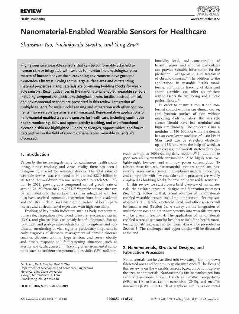
Nanomaterial-enabled wearable sensors are typically formed by depositing nanomaterials onto the surface or embedding them inside a plastic, fabric or polymer substrate/matrix.[13,14] Distribution of nanomaterial fillers has a crucial influence on the mechanical and electrical properties of the sensors.[15–17] More discussions on the influence of the filler distribution and novel dispersion techniques to achieve uniform distribution can be found in previous published review papers.[18–20] In addition to the intrinsic good stretchability of nanomaterials, structural engineering is commonly used to enhance the stretchability. In a percolative network with nanomaterials overlapped with each other, the rearrangement and sliding of nanomaterials relative to the substrate or matrix can increase the stretchability by miti-gating the strain experienced by the nanomaterials themselves. Similarly, for a fragmented structure with connected islands, the opening and enlargement of cracks can relieve most of the strain. To further enhance the stretchability, deformable struc-tures can be introduced. For example, nanomaterials can be pat-terned into horseshoe, filamentary serpentine or fractal shapes to better accommodate the strain.[21,22] As shown in Figure 1a, CuNW mesh was patterned into serpentine shape and achieved a stretchability up to 80%.[23] Wavy structures can be introduced by strategies such as prestrain-release-buckling and stretching-release-buckling.[18] By embedding the silver NWs (AgNWs) just below the surface of polydimethylsiloxane (PDMS) and then stretching and releasing the PDMS substrate, wavy structures were generated in the AgNW/PDMS composite (Figure 1b) that improved the stretchability of the AgNW/PDMS conductors.[24] Figure 1c shows the biaxially buckled CNT films fabricated by stretching and releasing the PDMS substrate in two direc-tions.[25] Porous structures such as sponge and foam were also employed to improve the stretchability.[26–28] Figure 1d presents a printed pattern based on CNT-filled elastomer with porous structure.[26] The porous structure was induced by evaporating the added reverse micelles. The porous structure improves the stretchability and decreases the modulus of the conductive elas-tomer. Nanomaterial-based wearable sensors can be fabricated
Shanshan Yao received her B.S. in microelectronics and M.S. in microelectronics and solid-state electronics from Xi’an Jiaotong University in 2009 and 2012, respectively. She received her Ph.D. degree in mechanical engineering from North Carolina State University in 2016. She is cur-rently a postdoctoral research scholar in North Carolina
State University. Her research interests include growth, nanomechanics, and device applications of nanowires and 2D materials in flexible and wearable electronics.
Yong Zhu is a Professor in Departments of Mechanical and Aerospace Engineering, Biomedical Engineering, and Materials Science and Engineering at North Carolina State University. He received his B.S. degree in Mechanics and Mechanical Engineering from the University of Science and Technology of China in 1999, and his
M.S. and Ph.D. degrees in Mechanical Engineering from Northwestern University in 2001 and 2005, respectively. Zhu’s research interests include mechanics of nanomate-rials, micro/nano-electromechanical systems, and flexible/stretchable electronics.
using all intrinsically flexible/stretchable materials,[29] or can be integrated by bridging the relative stiff components with highly deformable interconnects.[30–32] Deformation of the inter-connects can absorb most of the strain and impart the nano-material-based sensors with large stretchability. For detailed description of structural designs, we refer the readers to several recently published review papers.[18,33–35]
To fabricate the wearable sensors, conventional lithographic processes can be extended to pattern nanomaterials.[23,36–38] Solution based processing methods such as spray coating,[25,39,40] drop casting,[41–45] spin coating,[46,47] dip coating,[48] vacuum fil-tration,[49–51] and layer-by-layer assembly[52] were commonly used for fabrication of nanomaterial-based sensors. Direct spinning of CNTs onto a substrate or into yarns[53–55] and elec-trospinning of nanofibers or NWs were reported to produce fiber-like nanomaterials.[56–59] In addition, novel direct printing or writing techniques[60,61] such as inkjet printing,[62] gravure printing,[63,64] screen printing,[65–67] nozzle jet printing,[26] and direct writing[68,69] enabled the fabrication of wearable sensors that possess complex patterns with high resolution.
Adv. Healthcare Mater. 2018, 7, 1700889
© 2017 WILEY-VCH Verlag GmbH & Co. KGaA, Weinheim1700889 (3 of 27)
www.advancedsciencenews.com www.advhealthmat.de
3. Nanomaterial-Enabled Wearable Sensors
In this section, we summarize the recent advances in nano-material-based wearable physical sensors (i.e., temperature sensors, electrophysiological sensors, strain sensors, tactile sensors, UV sensors), wearable chemical sensors (i.e., electro-chemical sensors, gas sensors) and wearable multifunctional sensors.
3.1. Wearable Temperature Sensors
Body temperature is one of the vital signals, which is closely related to various types of illnesses/diseases (e.g., heat stroke, congestive heart failure, infection, fever), physiological status, and cognitive status of human body.[6,70–72] Body temperature needs to be monitored in real time and with high precision. Wearable temperature monitoring requires good flexibility, fast response, wide sensing range (25–50 °C) and high sensitivity (down to ±0.1 °C in the temperature range of 37–39 °C and ±0.2 °C for below 37 °C and above 39 °C).[6,73,74] The thermore-sistive effect is typically used for temperature measurement (Table 1). Resistivity of metallic materials and semiconducting materials shows a dependency on temperature due to thermally induced charge carrier scattering (resistivity increase, positive temperature coefficient (PTC) type) or thermally enhanced
charge transport (resistivity decrease, negative temperature coefficient (NTC) type).[49,70]
Photolithographically patterned serpentine CuNW mesh (Figure 1a) showed an increase in resistance with the tem-perature (the PTC type). The temperature sensitivity was ≈0.7 Ω °C−1 over the range of RT to 50 °C.[23] Graphene[47,49,75–78] and CNTs[79–81] have been widely adopted as the thermoresis-tive sensing elements for wearable temperature sensors. Gra-phene nanowalls, made of vertically aligned interlaced gra-phene nanosheets, were transferred onto a PDMS substrate to fabricate flexible temperature sensors (Figure 2a).[78] With the thermal expansion of the PDMS substrate at elevated tempera-ture, the interlaced graphene nanowall network became more loosely connected, resulting in an increase in resistance. In a NTC type temperature sensor based on graphene sensing ele-ments and AgNW electrodes (Figure 2b,c), the temperature sensitivity can be tuned by strain. Tensile strain decreased the contact area between adjacent crumpled graphene and increased the contact resistance, leading to higher sensitivity at larger strain.[49]
The thermoresistive material can also be used to fabricate thermal-responsive field-effect transistors (FETs),[47,77] which can detect minute temperature as small as 0.1 °C.[77] Figure 2d shows an all-elastomeric temperature sensor with poly(3,4- ethylenedioxythiophene):poly(styrenesulfonate) (PEDOT:PSS)/polyurethane (PU) composite as the source, drain and gate
Adv. Healthcare Mater. 2018, 7, 1700889
Figure 1. Nanomaterial-enabled wearable sensors with deformable structures. a) Optical image of a device with serpentine CuNW mesh floating on the water (scale bar: 1 cm). The inset shows the enlarged image of the filamentary serpentine structure (scale bar: 1.5 mm). Reproduced with permission.[23] b) SEM images of AgNW networks (left) and wavy structures generated in AgNW/PDMS composite by stretching and releasing the strain (right). The inset shows the cross-sectional image of the wavy structures. Reproduced with permission.[24] c) Schematic illustration (left) and corresponding AFM phase image (right) of buckled CNT films on PDMS substrate achieved by stretching and releasing the substrate along two axes. Dashed and solid white boxes indicate CNTs buckled along the horizontal and vertical axis, respectively. Scale bar: 600 nm. Reproduced with permission.[25] Copyright 2011, Nature Publishing Group. d) A printed pattern based on CNT-filled elastomer with porous structure. Reproduced with permission.[26]

© 2017 WILEY-VCH Verlag GmbH & Co. KGaA, Weinheim1700889 (4 of 27)
www.advancedsciencenews.com www.advhealthmat.de
electrodes, PU as the gate dielectric and reduced graphene oxide (rGO) nanosheets/PU nanocomposite as the thermoresis-tive channel layer.[47] Owing to the enhanced electron hopping across the rGO nanosheet junctions at increasing tempera-ture, the IDS increases with the temperature. High sensitivity
of ≈1.34% °C−1 with a temperature interval of 0.2 °C was demonstrated.
In addition to the thermoresistive effect, other effects such as pyroelectric effect[62,82] and thermoelectric effect[83] were also utilized in wearable temperature sensors. Pyroelectric
Adv. Healthcare Mater. 2018, 7, 1700889
Table 1. Summary of the performances of representative nanomaterial-enabled wearable temperature sensors reported.
Materials Sensing mechanism Sensitivity Sensing range Stretchability Applications
Graphene/PDMS[49] Thermoresistive −1.05% °C−1 (zero strain),
−2.11 °C−1 (50% strain)
30–100 °C 50% –
CNT/self-healing polymer[81] Thermoresistive – 0–80 °C ≈70% Soft robotics
Graphene nanowall/PDMS[78] Thermoresistive 0.214 °C−1 25–120 °C – –
FET with rGO/PVDF-TrFE channel[77] Thermoresistive – 30–80 °C Flexible –
FET with rGO/PU channel[47] Thermoresistive 1.34% °C−1 30–80 °C 70% Monitoring of skin temperature during
drinking hot water and workout
Polyaniline nanofiber with CNT TFT[30] Thermoresistive 1.0% °C−1 15–45 °C Biaxial 30% Electronic skin
rGO[172] Thermoresistive 0.55% °C−1 0–100 °C 3% Electronic skin
CNT-PEDOT:PSS[196] Thermoresistive ≈0.25% °C−1 21–80 °C – Electronic skin
CNT-PEDOT:PSS[79] Thermoresistive ≈0.61% °C−1 22–48 °C – Smart bandage, monitoring of skin
temperature during lunch and exercise
CuNW mesh[23] Thermoresistive ≈0.7 Ω °C−1 RT–48 °C 80% –
rGO foam[83] Thermoelectric – 10–97 °C Flexible Human touch sensing
ZnO NW/PU fiber[82] Pyroelectric 39.3% °C−1 (zero strain),
16.8% °C−1 (100% strain)
25–50 °C 150% Monitoring of mouth/nose breathing
Figure 2. Nanomaterial-enabled wearable temperature sensors. a) Schematic diagram of the graphene nanowall/PDMS temperature sensor. Repro-duced with permission.[78] Copyright 2015, Royal Society of Chemistry. b) Schematic diagram of the stretchable graphene thermistor consisting of graphene thermoresistive sensing element and AgNW electrodes. c) Image of the stretchable graphene thermistor shown in (b) being twisted. b,c) Reproduced with permission.[49] Copyright 2015, American Chemical Society. d) Schematic of an all-elastomeric transistor using rGO/PU as the temperature sensing element. Reproduced with permission.[47] e) Biaxially stretchable active matrix temperature sensor array consisting of polyaniline nanofiber based temperature sensors, SWCNT based TFTs, and liquid metal as interconnects. f) The performance of the temperature sensor shown in (e) under a biaxial strain of 30%. e,f) Reproduced with permission.[30]

© 2017 WILEY-VCH Verlag GmbH & Co. KGaA, Weinheim1700889 (5 of 27)
www.advancedsciencenews.com www.advhealthmat.de
ZnO NWs were grown onto PU fibers to form stretchable ZnO NW-PU composites.[82] Owing to the pyroelectric effect, the current increased with the increase in temperature. High sensitivity of 39.3% °C−1 was achieved when no strain was applied, which decreased to 20.1% °C−1 under 50% strain and to 16.8% °C−1 under 100% strain. Freestanding graphene oxide foam was employed as a thermoelectric temperature sensing element without external power supply.[83] The sensor can con-vert the difference in temperature to current signal through the Seebeck effect. The same sensor can also be used to measure human touch and pressure.
Very few reported temperature sensors can maintain the sensitivity while being stretched. Stretchable active matrix temperature sensor array was developed, which consisted of stretchable temperature sensors based on polyaniline nanofibers and active matrix backplane based on single walled CNT (SWCNT) thin film transistors (TFTs) (Figure 2e).[30] In an active matrix based device, the state of each pixel is con-nected with a transistor, which serves as a switch to actively control the state of the pixel.[30,84,85] Both the temperature sensor and active matrix were fabricated on PET substrate and a eutectic alloy liquid metal of Galinstan was used as the stretchable interconnects between the active components. Under stretching, the liquid metal interconnections accommo-dated the strain in order to minimize the strain experienced by the active components. A 5 × 5 active matrix temperature array was able to maintain its performance even under biaxial stretching of 30% (Figure 2f).
3.2. Wearable Electrophysiological Sensors
Electrophysiological sensors, also called biopotential electrodes, record the bioelectric signals in biological tissues.[86] Among representative bioelectric signals, ECG measures the electrical activity of the heart, which represents one of the most com-monly used tool to diagnose and manage cardiovascular dis-eases.[87] Electromyogram (EMG) measures the electrical activity of muscles, which plays an important role in evaluating the health of the muscle tissues and nerves, and diagnosing neu-romuscular disorders such as Parkinson’s disease, Duchenne muscular dystrophy and spinal muscular atrophy.[88] Electroen-cephalogram (EEG) measures the electrical activity of the brain
and is a powerful tool in developing novel brain–computer interfaces and diagnosing diseases related to brain functions and neurological conditions, such as sleep disorders, tumor, and brain disorders (e.g., epilepsy, coma, confusion, difficul-ties in memory and thinking).[89,90] Electrophysiological sensors that can continuously monitor electrophysiological activities will greatly promote their applications in diagnosis, rehabilita-tion, sports performance tracking, and human–machine inter-faces. However, the commonly used pregelled (wet) electrodes are unsuitable for continuous measurements. The gel dries with time, leading to deteriorated signal quality. Repeatedly reapplication of new gel is needed, which is inconvenient and sometimes infeasible. Moreover, the gel can potentially trigger dermal irritation and allergic reactions,[87,91] especially under long-term wearing.
Significant efforts have been devoted to developing gel-free (dry) wearable electrodes that can form intimate contact with skin and can be conformably worn for long-term while main-taining good signal quality without provoking skin irritations, as summarized in Table 2. Among all the candidates, nano-material-based wearable dry electrodes have shown promising potential. The excellent compliance of nanomaterial-based elec-trodes enables good electrical interface between the electrodes and skin, without the need of a gel layer. Metallic NWs, such as AgNWs,[92] CuNWs,[23] and platinum NWs (PtNWs),[93] were used to develop dry electrodes owing to their high conductivity. Our group recently developed highly conductive and stretchable AgNW/PDMS dry electrodes for ECG and EMG sensing, where AgNWs were embedded just below the surface of the biocom-patible, low-cost, and stretchable PDMS matrix.[92] The AgNW/PDMS electrodes can be worn on the wrist in the form of a wristband (Figure 3a). A comparison between the AgNW/PDMS dry electrodes and the commercial pregelled Ag/AgCl electrodes was made, under three conditions—resting, swinging arms (one degree of movement), and jogging (two degrees of move-ment), as shown in Figure 3b. It turned out that the AgNW/PDMS dry electrodes showed comparable performance with the pregelled Ag/AgCl electrodes when the subject was resting and outperformed the pregelled Ag/AgCl electrodes with less motion artifacts under movements, which was attributed to the conformal contact between the AgNW/PDMS electrodes and the skin even under movements. Ultrathin electrophysio-logical monitors were fabricated with the photolithographically
Adv. Healthcare Mater. 2018, 7, 1700889
Table 2. Summary of the performances of representative nanomaterial-enabled wearable electrophysiological sensors reported.
Materials Electrode type Conductivity Stretchability Advantages Applications
CNT/PDMS[94] Contact 10−4–10 S m−1 for CNT concentration
of 1–4.5 wt%
45% Gel-free, skin compatible (7 d) ECG
CNT/aPDMS[95] Contact 16.4 S m−1 for CNT concentration
of 2.5 wt%
>100% Gel-free, self-adhesive, epidermis-like, skin
compatible (7 d)
ECG
PtNW/paper[93] Contact – Flexible Gel-free ECG
AgNW/PDMS[92] Contact >5 × 10⁵ S m−1 50% Gel-free ECG/EMG
CNT/graphene/graphite/
carbon black/PDMS[100]
Contact ≈100 Ω cm (≈1 S m−1) 100% Gel-free, self-adhesive, waterproof,
water-repellent
ECG
CuNW mesh[23] Contact – 80% Gel-free, epidermis-like ECG/EMG
CNT/aPDMS[96] Capacitive – – Gel-free, self-adhesive EEG

© 2017 WILEY-VCH Verlag GmbH & Co. KGaA, Weinheim1700889 (6 of 27)
www.advancedsciencenews.com www.advhealthmat.de
patterned serpentine CuNW mesh, which consisted of refer-ence, ground, and measurement electrodes (Figure 3c,d).[23] By attaching the electrodes onto the forearm (for EMG recording) and chest (for ECG recording), high-quality EMG and ECG recordings were captured, respectively.
In addition to metallic NWs, CNTs have also been used for dry electrodes by dispersing CNTs into a polymer matrix.[94–96] CNT/PDMS composites exhibited good conductivity under ten-sile strain up to 45%.[94] The dry electrodes showed robust per-formance under static condition (resting), walking (3 km h−1), power walking (5 km h−1) and sweating. A 7 d in vitro cyto-toxicity test for skin fibroblast cells cultured on CNT/PDMS electrodes and 7 d continuous wearing of the electrodes on the arms were conducted. The high viability (exceeding 95%) of the skin fibroblast cells and negligible side effects on exami-nees confirmed the good biocompatibility of CNT/PDMS dry electrodes.
Besides the conductive gels used in the pregelled electrodes, the adhesives used in such electrodes were also reported to cause skin irritation. The strong adhesive force leads to skin fragments during the mechanical peeling process.[97,98]
Moreover, the adhesives cannot be reused. Hence researchers are seeking alternative electrodes without the adhesive, which can self-adhere to the skin and be repeatedly used. In order to achieve self-adhesion, CNTs were hydrodynamically dispersed in an adhesive PDMS (aPDMS).[95] With a patterned Au/Ti/polyimide metal layer, an aPDMS frame layer and a CNT/aPDMS sensing layer, the resulting electrode patch (Figure 3e) was ultrathin (120 µm), extremely compliant (modulus of 27.5 kPa) and waterproof. The patch showed high adhesion force (initially 1.1 and 1.0 N cm−2 after cleaning) and reliable ECG quality even after attaching and detaching for 30 times. Good biocompatibility was proved by culturing fibroblast cells on the CNT/aPDMS and after continuously wearing the elec-trodes for a week. Similar CNT/PDMS electrodes were also demonstrated for capacitive EEG recordings.[96] The capacitive electrodes do not form direct electrical contact with skin, which makes them reusable, electrically safe and free from irritating the skin.[99]
The self-adhesion characteristic can also be imparted by patterning conductive hybrid carbon nanocomposites con-sisting of 1D CNTs and 2D graphene nanopower fillers into
Adv. Healthcare Mater. 2018, 7, 1700889
Figure 3. Nanomaterial-enabled wearable electrophysiological sensors. a) Images showing the AgNW/PDMS dry electrode with a metal snap (top) and AgNW/PDMS dry electrode attached on the wrist using a Velcro strap (bottom). b) Comparison between commercial Ag/AgCl electrodes and AgNW/PDMS dry electrodes under resting, swing arms and jogging. a,b) Reproduced with permission.[92] Copyright 2015, Royal Society of Chemistry. c) Optical image of CuNW mesh based electrophysiological monitor with reference, measurement, and ground electrodes. Scale bar: 5 mm. d) The electrophysi-ological monitor worn on the forearm for EMG sensing (left, scale bar: 2 cm) and the measured EMG signals corresponding to clenching the first every 2 s (right). c,d) Reproduced with permission.[23] e) Schematic of a self-adhesive epidermis-like ECG patch based on CNT/aPDMS. Reproduced with permission.[95] Copyright 2014, Nature Publishing Group. f) Conductive dry adhesives with hybrid 1D–2D conductive fillers and gecko-inspired hierarchical structures for ECG sensing. Reproduced with permission.[100] Copyright 2016, American Chemical Society.
© 2017 WILEY-VCH Verlag GmbH & Co. KGaA, Weinheim1700889 (7 of 27)
www.advancedsciencenews.com www.advhealthmat.de
gecko-inspired high-aspect-ratio microstructures (Figure 3f).[100] High stretchability (100%) and good conductivity (≈100 Ω cm) resulted in good ECG recording quality. High-aspect-ratio pil-lars provided high adhesion force (≈1.3 N cm−2) even after 30 times of use and superhydrophobicity (contact angle of ≈151° for deionized water). The water-repellant, self-cleaning electrodes can be used underwater and under various move-ment conditions such as wrist curling, squatting and writing. Electrodes with good conductivity, low motion artifact, good skin compatibility, and reusable adhesive in a dry form factor are ideal for long-term and continuous electrophysiological recording.
3.3. Wearable Strain Sensors
Strain sensors convert mechanical deformation into electrical signal.[101] Conventional metal thin film based strain sensors have a limited strain range and a relatively small gauge factor (GF), relative change in electrical signal divided by the applied strain (typically ≈2),[101,102] which make them challenging for wearable applications. Monitoring of human body would require sensors with a large strain range (e.g., to monitor large deformations associated with human joint motions, where the strain can be as large as 100%) and/or high sensitivity (e.g., to monitor subtle deformations induced by blood pulse, breathing, facial expression, and so on, where the strain can be as small as 0.1%).[6,103] Wearable strain sensors that possess high stretchability and/or high sensitivity, either mounted on skin or integrated into clothing, have been developed based on transduction mechanisms such as piezoresistivity, piezocapaci-tivity, and piezoelectricity (Table 3).
3.3.1. Resistive Strain Sensors
A resistive strain sensor detects the strain by measuring the resistance change. Most of nanomaterial-based resistive strain sensors consist of a network/array of nanomaterials deposited on top of a substrate or embedded inside a polymer matrix. Conductive pathways are established by the overlapping nanomaterials, which tend to slide on the surface or inside the poly mer matrix under strain due to the weak interfacial bonding between the nanomaterials themselves and between nanomaterials and the polymer. For a material under strain, the GF can be expressed by[104]
R RGF
/1 2
/ε
ν ρ ρε
( )= ∆ = + + ∆
(1)
where ε is the applied strain, ν is the Poisson’s ratio, R and ΔR are the initial resistance (zero strain) and the change in resistance, respectively, ρ and Δρ are the initial resistivity and the change in resistivity, respectively. For strain sensors based on nanomaterial composites, the resistance change originates from four mechanisms: (1) the change in the geometry of the nanomaterials themselves and the composites; (2) change in resistivity of nanomaterial fillers due to the intrinsic piezore-sistive effect (second term in Equation (1)); (3) strain induced
separation of neighboring nanomaterials and the resulting modified tunneling resistance for nanomaterials not electri-cally conducting with each other;[105,106] (4) decreased number of percolation pathways between nanomaterials, mainly due to disconnection (or sliding) between nanomaterials or propa-gation of microcracks under strain, which leads to increased contact resistance.[107] Separation and/or sliding of nanomate-rials under strain (especially large strain) results in small strain experienced by the nanomaterials themselves. In this case the resistance change due to the first two mechanisms is relatively small, while that due to the last two mechanisms becomes dominant.
A strain sensor based on strain-modified electron tunneling effect was reported for CNT and graphene nanocomposites with a strain range up to 200% (2nd mechanism).[108–110] Numerical simulations[111–114] were conducted to study the behavior of resistive strain sensors. For example, the resistive response for AgNW-PDMS sensor was highly correlated to the aspect ratio and density of AgNWs.[111,114] Higher density AgNW networks and higher aspect ratio resulted in better linearity but lower sen-sitivity. For strain sensors with graphene flakes, decreasing the film thickness or lowering the density in graphene flakes (and therefore increasing the initial resistance) enhanced the sensi-tivity.[113] Decreasing the film thickness also decreased the max-imum strain range. Simulation results on AgNP/PDMS strain sensors revealed that the strain-resistance behavior is affected by the size and the number of cracks.[112] Higher sensitivity was observed for larger cracks or higher number of cracks.
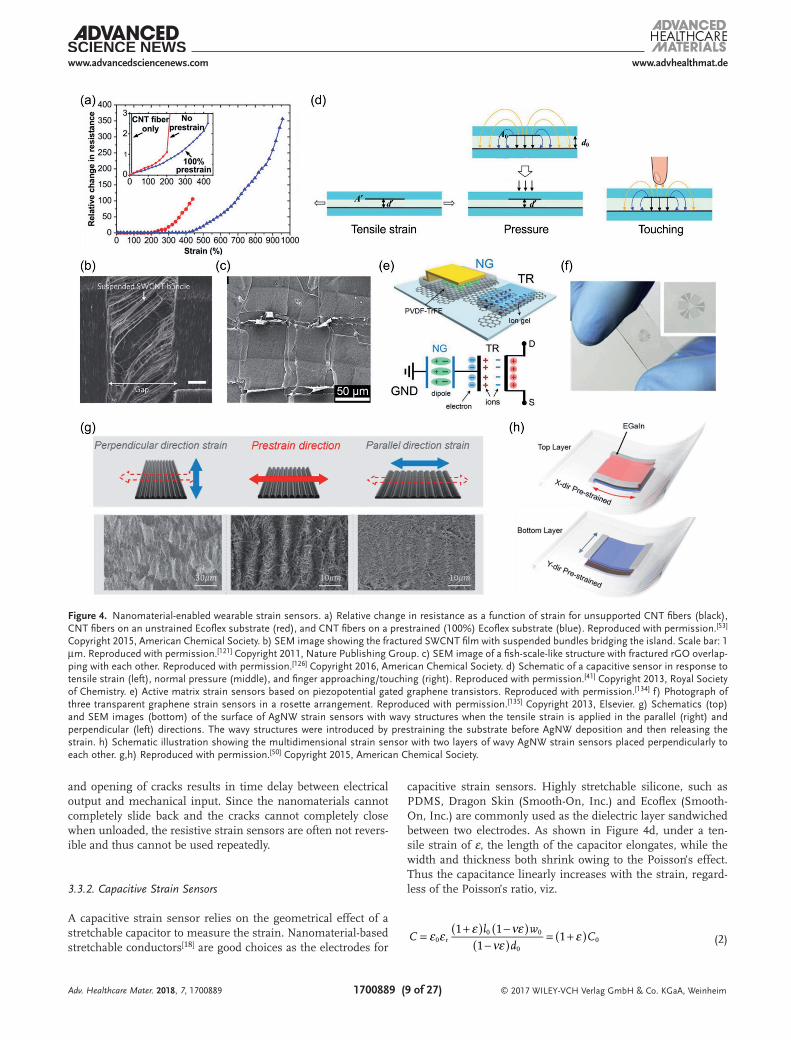
Wearable strain sensors based on the disconnection (sliding) have been fabricated in a number of ways such as depositing AuNPs onto PDMS,[115] embedding AgNWs into PDMS,[111] electrospinning Au nanotroughs onto PDMS,[116] mixing SWCNTs with self-healing hydrogel,[117] sandwiching SWCNTs between two PU-PEDOT:PSS electrodes,[46] aligning CNTs onto a substrate,[53,118] growing well-aligned ZnO NWs on the tex-tile substrate,[119] laser-scribing graphene coated on PET sub-strate,[113] encapsulating graphene–nanocellulose nanopaper in PDMS,[51] and infusing graphene into rubber.[120] Tensile strain can decrease the overlapped area between nanomate-rials and decrease the number of conductive pathways, leading to an increase in resistance. Sandwiched structures of PU-PEDOT:PSS/SWCNT/PU-PEDOT:PSS showed stretchability of 100% and high GF between 50.8 and 837.1 at 3.5% strain.[46] The sensitivity was tunable by varying the loading of SWCNTs. Graphene–nanocellulose nanopaper was capable of detecting the small strain with ultrahigh sensitivity with GF of 502 at 1% strain and 2427 at 6% strain.[51] In addition to high sensi-tivity, large sensing range was also achieved for resistive strain sensors based on the disconnection mechanism. Strain sen-sors fabricated by dry-spinning CNT fibers onto a prestrained (100%) Ecoflex substrate exhibited a GF of 0.54 for strain below 400% and 64 for strain between 400% and 960% (Figure 4a).[53] Very recently, SWCNT/hydrogel was reported to be able to detect strain as large as 1000% owing to the self-healing capa-bility of the hydrogel.[117] GF of 0.24 for strain within 100% and 1.51 at 1000% strain was realized.
For the change in contact resistance due to crack propaga-tion, cracks are typically initiated at stress concentrated loca-tions under stretching. The opening and propagation of cracks
Adv. Healthcare Mater. 2018, 7, 1700889
© 2017 WILEY-VCH Verlag GmbH & Co. KGaA, Weinheim1700889 (8 of 27)
www.advancedsciencenews.com www.advhealthmat.de
leads to increase in the resistance and on the contrary, the closing of the cracks leads to recovery of the resistance. Exam-ples include strain sensors based on AgNPs coated fiber mat,[56] AuNW/latex,[44,68] CNT/PDMS,[121] CNT-Ecoflex,[39] SWCNT paper-PDMS,[122] graphene/PDMS,[123] graphene woven fabric/PDMS,[103,124] graphene coated yarns,[52] fragmentized gra-phene foam/PDMS,[125] and fish-scale-like rGO.[126] Figure 4b shows the fractured SWCNT film attached onto PDMS.[121] The SWCNT film ruptured into islands with the SWCNT bundles bridging the gaps and maintained the electrical connection. Figure 4c indicates a fish-scale-like rGO structure generated by stretching the first layer of rGO film to 50% to generate facture, applying the second layer of rGO film onto the stretched film, stretching the two layers to 100% to generate more cracks and then releasing the strain.[126] The fractured rGO overlapped with each other to form the fish-scale-like structure. The resulting
strain sensor was able to detect the strain as low as 0.1%. AuNW-based strain sensors showed an even lower detection limit of 0.01%.[44] By using wrinkled CNTs enabled by heating the pre-strained shape memory polymer above its glass transition tem-perature, the fabricated CNT-Ecoflex strain sensor could sense the strain up to 700%.[39] In the low-strain range (0–400%), low GF of 0.65 was obtained. The CNT film started to facture under a strain beyond 400%, leading to a higher GF of 48.
While most resistive strain sensors exhibit large stretch-ability and high sensitivity, many suffer from nonlinear response, large hysteresis, and irreversibility.[107] When the applied strain is released, it is difficult for the nanomaterials to slide back to the initial position or for the cracks to be com-pletely closed. Due to the viscoelasticity of polymers and the friction between the nanomaterials and the polymer matrix during loading and unloading, rearrangement of nanomaterials
Adv. Healthcare Mater. 2018, 7, 1700889
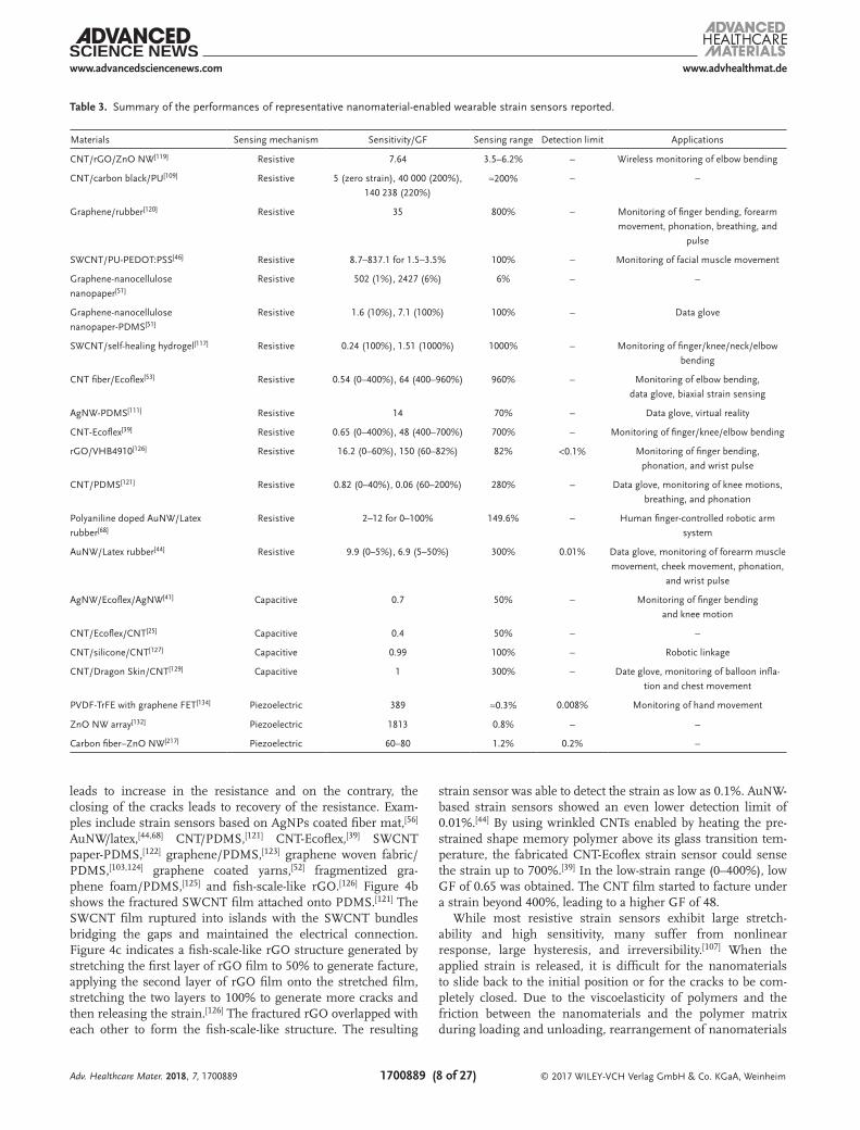
Table 3. Summary of the performances of representative nanomaterial-enabled wearable strain sensors reported.
Materials Sensing mechanism Sensitivity/GF Sensing range Detection limit Applications
CNT/rGO/ZnO NW[119] Resistive 7.64 3.5–6.2% – Wireless monitoring of elbow bending
CNT/carbon black/PU[109] Resistive 5 (zero strain), 40 000 (200%),
140 238 (220%)≈200% – –
Graphene/rubber[120] Resistive 35 800% – Monitoring of finger bending, forearm
movement, phonation, breathing, and
pulse
SWCNT/PU-PEDOT:PSS[46] Resistive 8.7–837.1 for 1.5–3.5% 100% – Monitoring of facial muscle movement
Graphene-nanocellulose
nanopaper[51]
Resistive 502 (1%), 2427 (6%) 6% – –
Graphene-nanocellulose
nanopaper-PDMS[51]
Resistive 1.6 (10%), 7.1 (100%) 100% – Data glove
SWCNT/self-healing hydrogel[117] Resistive 0.24 (100%), 1.51 (1000%) 1000% – Monitoring of finger/knee/neck/elbow
bending
CNT fiber/Ecoflex[53] Resistive 0.54 (0–400%), 64 (400–960%) 960% – Monitoring of elbow bending,
data glove, biaxial strain sensing
AgNW-PDMS[111] Resistive 14 70% – Data glove, virtual reality
CNT-Ecoflex[39] Resistive 0.65 (0–400%), 48 (400–700%) 700% – Monitoring of finger/knee/elbow bending
rGO/VHB4910[126] Resistive 16.2 (0–60%), 150 (60–82%) 82% <0.1% Monitoring of finger bending,
phonation, and wrist pulse
CNT/PDMS[121] Resistive 0.82 (0–40%), 0.06 (60–200%) 280% – Data glove, monitoring of knee motions,
breathing, and phonation
Polyaniline doped AuNW/Latex
rubber[68]
Resistive 2–12 for 0–100% 149.6% – Human finger-controlled robotic arm
system
AuNW/Latex rubber[44] Resistive 9.9 (0–5%), 6.9 (5–50%) 300% 0.01% Data glove, monitoring of forearm muscle
movement, cheek movement, phonation,
and wrist pulse
AgNW/Ecoflex/AgNW[41] Capacitive 0.7 50% – Monitoring of finger bending
and knee motion
CNT/Ecoflex/CNT[25] Capacitive 0.4 50% – –
CNT/silicone/CNT[127] Capacitive 0.99 100% – Robotic linkage
CNT/Dragon Skin/CNT[129] Capacitive 1 300% – Date glove, monitoring of balloon infla-
tion and chest movement
PVDF-TrFE with graphene FET[134] Piezoelectric 389 ≈0.3% 0.008% Monitoring of hand movement
ZnO NW array[132] Piezoelectric 1813 0.8% – –
Carbon fiber–ZnO NW[217] Piezoelectric 60–80 1.2% 0.2% –
© 2017 WILEY-VCH Verlag GmbH & Co. KGaA, Weinheim1700889 (9 of 27)
www.advancedsciencenews.com www.advhealthmat.de
and opening of cracks results in time delay between electrical output and mechanical input. Since the nanomaterials cannot completely slide back and the cracks cannot completely close when unloaded, the resistive strain sensors are often not revers-ible and thus cannot be used repeatedly.
3.3.2. Capacitive Strain Sensors
A capacitive strain sensor relies on the geometrical effect of a stretchable capacitor to measure the strain. Nanomaterial-based stretchable conductors[18] are good choices as the electrodes for
capacitive strain sensors. Highly stretchable silicone, such as PDMS, Dragon Skin (Smooth-On, Inc.) and Ecoflex (Smooth-On, Inc.) are commonly used as the dielectric layer sandwiched between two electrodes. As shown in Figure 4d, under a ten-sile strain of ε, the length of the capacitor elongates, while the width and thickness both shrink owing to the Poisson’s effect. Thus the capacitance linearly increases with the strain, regard-less of the Poisson’s ratio, viz.
Cl w
dC
1 11
10 r0 0
00ε ε ε νε
νεε( ) ( )
( )( )= + −
−= +
(2)
Adv. Healthcare Mater. 2018, 7, 1700889
Figure 4. Nanomaterial-enabled wearable strain sensors. a) Relative change in resistance as a function of strain for unsupported CNT fibers (black), CNT fibers on an unstrained Ecoflex substrate (red), and CNT fibers on a prestrained (100%) Ecoflex substrate (blue). Reproduced with permission.[53] Copyright 2015, American Chemical Society. b) SEM image showing the fractured SWCNT film with suspended bundles bridging the island. Scale bar: 1 µm. Reproduced with permission.[121] Copyright 2011, Nature Publishing Group. c) SEM image of a fish-scale-like structure with fractured rGO overlap-ping with each other. Reproduced with permission.[126] Copyright 2016, American Chemical Society. d) Schematic of a capacitive sensor in response to tensile strain (left), normal pressure (middle), and finger approaching/touching (right). Reproduced with permission.[41] Copyright 2013, Royal Society of Chemistry. e) Active matrix strain sensors based on piezopotential gated graphene transistors. Reproduced with permission.[134] f) Photograph of three transparent graphene strain sensors in a rosette arrangement. Reproduced with permission.[135] Copyright 2013, Elsevier. g) Schematics (top) and SEM images (bottom) of the surface of AgNW strain sensors with wavy structures when the tensile strain is applied in the parallel (right) and perpendicular (left) directions. The wavy structures were introduced by prestraining the substrate before AgNW deposition and then releasing the strain. h) Schematic illustration showing the multidimensional strain sensor with two layers of wavy AgNW strain sensors placed perpendicularly to each other. g,h) Reproduced with permission.[50] Copyright 2015, American Chemical Society.

© 2017 WILEY-VCH Verlag GmbH & Co. KGaA, Weinheim1700889 (10 of 27)
www.advancedsciencenews.com www.advhealthmat.de
where C0 indicates the initial capacitance, l0, w0, and d0 indi-cate the initial length, width and separation of the two elec-trodes respectively, ε0 and εr represent the dielectric constant for the vacuum and the dielectric layer respectively, ν rep-resents the Poisson’s ratios of the electrodes and the die-lectric. The theoretical GF of a capacitive sensor is thus given by
C CGF / 10ε= ∆ = (3)
The capacitance change shows a linear relationship with the applied strain. The reported GF varies between 0.4 and 1.3 due to the fringing fields associated with finite-size parallel-plate capacitors,[127] and the strain range varies between 50% and 300% depending on the stretchability of the electrodes and the dielectric.[24,25,41,43,127–131] For example, a capacitive strain sensor was fabricated with stretchable AgNW/PDMS conductors as the top and bottom electrodes and Ecoflex as the dielectric material. The sensor exhibited good linearity, GF of 0.7 and a sensing range of 50%.[41] Capacitive strain sensors possess good linearity with low hysteresis, fast response, and are less susceptible to over-shoot and creep.[107] While capacitive strain sensors exhibit smaller GFs than the resistive strain sensors, they are ideal for applications where the strain is relatively large. In addi-tion, the GFs of capacitive strain sensors remain constant in the entire strain range.
3.3.3. Piezoelectric Strain Sensors
Piezoelectric strain sensors are based on the piezoelectric char-acteristic of non-centrosymmetric materials, where electric charges are generated in response to applied strain. Various piezoelectric materials such as ZnO nanostructures,[40,132,133] poly(vinylidenefluoride-co-trifluoroethylene) (PVDF-TrFE)[134] and polylactic acid (PLA)[22] have been used to develop wear-able strain sensors. For instance, a wearable piezoelectric bending sensor was fabricated using ZnO nanorods (NRs) as strain sensing materials and AgNW-SWCNT composites as electrodes.[40] Since both the bending strain and bending rate affect the voltage area (the area underneath the voltage over a certain time range), the sensor can detect the bending curva-ture as well as the speed by measuring the change in voltage area. Another piezoelectric strain sensor was developed using two graphene electrodes and heterostructures of PLA/SWCNT as the sensing materials.[22] The addition of CNTs into piezo-electric PLA polymer enhanced the output current and voltage by eight and five times, respectively. Active matrix strain sen-sors were reported by Cho et al., where the piezopotential gen-erated by a piezoelectric PVDF-TrFE nanogenerator in response to external strain was used to gate the graphene transistor based active matrix (Figure 4e).[134] The active matrix strain sensor was able to detect a small strain range (up to 0.3%) with a high GF of 389 and an extremely low strain detection limit of 0.008%. Piezoelectric strain sensors typically have fast response, high gauge factor, low power consumption but lim-ited stretchability.[6] Piezoelectric sensors are more suitable for detecting dynamic stimuli.[19]
3.3.4. Multiaxial Strain Sensors
Most of the reported wearable strain sensors can only detect uniaxial strain. To measure multiaxial strain, techniques such as arranging multiple sensors with rosette configuration,[135,136] anisotropic electrical impedance tomography,[137] and stacking strain sensors with low cross-sensitivity along different direc-tions were adopted. For instance, three identical transparent graphene/PDMS strain sensors were arranged into Delta rosette with relative orientations of 120 °C, as shown in Figure 4f.[135] Similar rosette arrangements were also used for CNT–Ecoflex nanocomposite enabled strain sensors.[136] The multiaxial strain sensor in rosette configurations enables the detection of the amplitude and direction of the maximum principle strain. The electrical responses of a stretchable sensor along different axes are usually coupled due to Poisson’s effect. To make the strain sensor only responsive to strain in one direction, wavy AgNW percolation networks were introduced by a prestrain (100%)–release–buckling process.[50] Stretching along the prestrain direction leads to flattening of the wavy structure (Figure 4g), which accompanies an almost constant resistance. In contrast, without the wavy structure, significant resistance change was observed when the strain was applied along the perpendicular direction. Multidimensional strain sensors with decoupled response along two axes were fabricated by stacking two layers of prestrained AgNW strain sensors perpendicularly to each other, as shown in Figure 4h. A similar idea was applied for dry-spun CNT fibers,[53] which was able to detect biaxial strain up to 200% with a low cross-sensitivity between the two axes. The application of an array of such strain sensors in mapping the strain distribution was demonstrated.[50]
3.4. Wearable Tactile Sensors
Wearable tactile sensors, mainly pressure sensors and touch sensors, adopt similar transduction mechanisms as the strain sensors discussed above, out of which the most common are resistive and capacitive tactile sensors (Table 4). The resistive sensors rely on the change in geometry, material resistivity, tunneling resistance, or contact resistance to sense the pres-sure. The capacitive sensors rely on the geometrical effect and the change in dielectric properties to sense the pressure, and the disturbed fringing field to sense the touch. For wearable pressure sensors that are used for healthcare applications, the sensors should be highly compliant to accommodate the skin deformations and highly sensitive to capture small pressure associated with biosignals such as blood pulse or respiration, where pressure down to tens of Pa can be involved.[6,138]
Numerous materials and configurations have been reported for resistive pressure sensing. Pressure sensitive pathways can be formed using interlocked structures,[139–144] percolative net-works of nanomaterials,[57,145,146] microfabricated structures (e.g., micropyramids, micropillars),[147–149] porous structures (e.g., sponges, foams, porous rubbers)[26,150,151] and so forth. For example, Figure 5a presents the working principle of a pressure sensor using interlocked microdome array.[141] Applied pres-sure deforms the microdomes, enhancing the contact between them and thus decreasing the tunneling resistance. Figure 5b
Adv. Healthcare Mater. 2018, 7, 1700889

© 2017 WILEY-VCH Verlag GmbH & Co. KGaA, Weinheim1700889 (11 of 27)
www.advancedsciencenews.com www.advhealthmat.de
shows the structure of a hierarchical Pt-coated ZnO NW array in an interlocking configuration.[142] Detection of low frequency pressure relies on the piezoresistive response of ZnO NWs and detection of high frequency pressure relies on the piezoelectric behavior of ZnO NWs. Such dual-mode pressure sensors allow for ultrafast and ultrasensitive detection of both static and dynamic pressures. Pressure sensors made of electrospun silk nanofiber membranes achieved excellent piezoresistive response.[57] Low detection limit of 0.8 Pa, fast response time of less than 16.7 ms and superior sensitivity of 34.47 kPa−1 for low pressure range (0.8–400 Pa) and 1.16 kPa−1 for high pres-sure range (400–5000 Pa) were demonstrated. A cyclic test of 10 000 cycles confirmed the good stability. An array of resis-tive pressure sensors can be integrated with an active matrix backplane to enable low-signal-crosstalk spatial pressure map-ping. In nanomaterial-enabled active matrix pressure sensing, nanomaterials such as Ge/Si NWs[85] or semiconducting CNTs,[63,64,84] can be employed as the channel material for the
transistor. Figure 5c shows a representative work using CNT based TFTs and pressure-sensitive rubber (PSR) for active matrix pressure sensing.[84]
For the capacitive pressure sensing, taking a parallel-plate capacitor as an example (Figure 4d), the separation between two electrodes decreases with the pressure, resulting in an increase in capacitance. The relative change in capacitance can be expressed by
C
C
lw d
l w d
d
l w
l w
d
//
1 1
(1 )
1
(1 )0
r
r0 0 0 0
r
r0
0
0 0
0 0
0
r
r0
2
εε
εε
εν
εν
εεε
ενε
= =+
+
−=
+
−
(4)
where εr, d, l, and w represent the dielectric constant, separation between the two electrodes, length of the electrodes, and width of the electrodes, respectively, all under pressure (with sub-script 0 representing the initial parameters without pressure), ε represents the strain applied in the thickness direction due to
Adv. Healthcare Mater. 2018, 7, 1700889
Table 4. Summary of the performances of representative nanomaterial-enabled wearable pressure sensors reported.
Materials Sensing mechanism
Sensitivity Sensing range Detection limit Stretch-ability
Applications
Interlocked CNT/PDMS
microdome array[141]
Resistive 15.1 kPa−1 (<0.5 kPa) 59 kPa 0.2 Pa Flexible Monitoring of finger bending,
breathing, phonation, and snail
movement; pressure mapping
AuNW-impregnated tissue
paper[203]
Resistive 1.14 kPa−1 5 kPa 13 Pa 25% Monitoring of wrist pulse and
acoustic vibration, pressure
mapping
rGO flake[146] Resistive 40.8 kPa−1 (39–630 Pa),
0.007 kPa−1 (4–20 kPa)
20 kPa – Flexible Monitoring of finger and muscle
movement
Carbonized silk
nanofiber[57]
Resistive 34.47 kPa−1 (0.8–400 Pa),
1.16 kPa−1 (400–5000 Pa)
5 kPa 0.8 Pa – Monitoring of wrist pulse, chest
respiration, jugular venous pres-
sure, phonation, and pressure
during grabbing
Interlocked Pt-coated
ZnO NW array[142]
Resistive,
piezoelectric6.8 kPa−1 (static pressure < 2 kPa),
0.79 m s−2 (vibration),
0.02 dB (sound pressure)
12 kPa (static
pressure),
0.9 m s−2
(vibration),
85 dB (sound
pressure)
0.6 Pa (static pres-
sure), 0.1 m s−2
(vibration), ≈57 dB
(sound pressure)
Flexible –
AgNW/Ecoflex/AgNW[41] Capacitive 1.62 MPa−1 (<500 kPa),
0.57 MPa−1 (0.5–1.2 MPa)
1.2 MPa – 50% Pressure mapping
CNT/Ecoflex/CNT[25] Capacitive 0.23 MPa−1 1 MPa 50 kPa 50% Pressure mapping
AgNW-multiscale PDMS/
PVP or PMMA/Ag[158]
Capacitive 3.8 kPa−1 (45–500 Pa), 0.8 kPa−1
(500 Pa–2.5 kPa), 0.35 kPa−1 (2.5–4.5 kPa)
4.5 kPa – – Grip pressure sensing, pressure
mapping
AgNW /AgNW–PU/
AgNW[153]
Capacitive 5.54 kPa−1 (0–30 Pa), 0.88 kPa−1 (30–70 Pa). 70 Pa – Flexible Monitoring of knee/finger
bending, forearm muscular
movement and air blow
CNT/porous PDMS/air
gap/CNT[131]
Capacitive 0.7 kPa−1 (0–1 kPa), 0.14 kPa−1
(1–5 kPa), 0.005 kPa−1 (5–20 kPa)
20 kPa 2.5 Pa 30% Electronic skin
PDMS/indium tin oxide
with graphene FET[161]
Triboelectric ≈2% kPa−1 (0–10 kPa) 0.816–57.16 kPa <1 kPa Flexible Detection of finger touch
PVDF-TrFE nanofiber
array[58]
Piezoelectric 0.41–0.79 V kPa−1 (0–12 Pa), 1.1 V kPa−1
(0.4–2 kPa)
2 kPa 0.1 Pa – Accelerometer, orientation sensor
PVDF nanofiber mat[59] Piezoelectric 0.3 V kPa−1 (0–7 kPa) 80 kPa – 30% Monitoring of radial and
carotid pulses

© 2017 WILEY-VCH Verlag GmbH & Co. KGaA, Weinheim1700889 (12 of 27)
www.advancedsciencenews.com www.advhealthmat.de
the applied pressure, and ν represents the Poisson’s ratio. High pressure sensitivity can be achieved by using dielectric mate-rials with the following properties—low elastic modulus so as to cause a larger strain ε under a given pressure, increasing dielectric constant with pressure, or low Poisson’s ratio. For a pressure sensor, the relationship between the applied pressure and the thickness change of the dielectric and thus the capaci-tance change is typically nonlinear, which can be predicted (or designed) with finite element analysis.
Substantial efforts were devoted to improving the pressure sensitivity by using a softer material as the dielectric, or a dielectric that can show increasing dielectric constant under pressure.[152–154] Highly deformable dielectric materials can be realized by using commercial porous tapes,[43] creating microstructures in elastomers using a mold (e.g., the surface of matte glass,[155] a micromachined Si mold,[131] or the sur-face of lotus leaf[156]), creating porous elastomers using sugar cubes as the template,[157] or fabricating buckled structures through prestretching and releasing.[158] When the air gap is compressed, the effective dielectric constant is increased under pressure, as the dielectric constant of air is smaller than
that of the dielectric material used for the sensor. Figure 5d highlights a capacitive pressure sensor with CNT/PDMS as the two electrodes, an air gap and porous PDMS with hollow micropillars as the dielectric.[131] At low pressure range, the air gap was mainly compressed, leading to a high pressure sensitivity; at higher pressure range, the porous PDMS was compressed. Further increasing the pressure compressed the solid PDMS, accompanied with a much lower pressure sen-sitivity, as shown in Figure 5d. Figure 5e shows a capacitive pressure sensor based on multiscale-structured AgNW/PDMS electrodes fabricated by prestretching and hardening the top surface using UV treatment.[158] The pressure sensor dis-played high sensitivity of 3.8 kPa−1 for 45–500 Pa, 0.8 kPa−1 for 500 Pa to 2.5 kPa and 0.35 kPa−1 for 2.5–4.5 kPa. Another strategy to increase the effective dielectric constant is to add conductive fillers into the dielectric just below the percolation threshold.[153] Compression shortens the distance between the fillers, leading to an increased dielectric constant under pressure. AgNWs, for example, were added into PU as the filler.[153] Using AgNW/PU composite as the dielectric layer, ultrahigh capacitive sensitivity of 5.54 kPa−1 for pressure
Adv. Healthcare Mater. 2018, 7, 1700889
Figure 5. Nanomaterial-enabled wearable tactile sensors. a) Schematic showing the interlocked microdome array under pressure. Reproduced with permission.[141] Copyright 2014, American Chemical Society. b) Schematic of the Pt-coated hierarchical ZnO NW array in an interlocking configuration. Reproduced with permission.[142] c) Schematic illustration of a single pixel of the active matrix pressure sensor for instantaneous pressure visualization. Reproduced with permission.[84] Copyright 2013, Nature Publishing Group. d) A capacitive sensor with CNT/PDMS as the electrodes and an air gap and porous PDMS with hollow micropillars as the dielectric (left). Relative capacitance change as a function of applied pressure for dielectrics with and without the air gap or porous PDMS structures (right). Reproduced with permission.[131] e) SEM image of the multiscale AgNW/PDMS electrode fabri-cated by prestretching and hardening the top surface using UV treatment. Reproduced with permission.[158] Copyright 2015, Royal Society of Chemistry.
© 2017 WILEY-VCH Verlag GmbH & Co. KGaA, Weinheim1700889 (13 of 27)
www.advancedsciencenews.com www.advhealthmat.de
below 30 Pa and 0.88 kPa−1 for pressure between 30 and 70 Pa was achieved.
Besides the widely used resistive and capacitive mecha-nisms, progress has been made to develop wearable piezo-electric[22,58,59,159] and triboelectric[160–162] pressure sensors. Similar to piezoelectric strain sensors, the piezoelectric pres-sure sensors detect the applied pressure by measuring the accumulated electric charges. Freestanding electrospun PVDF-TrFE nanofiber arrays[58] or electrospun PVDF-TrFE nanofiber mat sandwiched between two electrodes[59] were fabricated for piezoelectric pressure sensing. Detection limit as low as 0.1 Pa and high sensitivity of 1.1 V kPa−1 for pressure range between 0.4 and 2 kPa were obtained.[58] Triboelectric pressure sensors can generate output signals under pressure due to the contact electrification.[163,164] They can function without using an external power source. In a representative work, a pressure-responsive triboelectric nanogenerator was used to gate the gra-phene based transistors.[161] Such graphene tribotronics showed a pressure sensitivity of ≈2% kPa−1 at pressure of 10 kPa.
In addition to pressure sensors, proximity or touch sensors have been developed to detect the proximity, approaching, or touching of an object, no matter whether it is in physical contact with the sensors or not. Touch sensing can be achieved using the capacitive mechanism in a capacitor configuration.[41,43,54,165,166] Different from strain and pressure sensors that rely on geomet-rical effect, a decrease in capacitance is seen for touch sensing, arising from the disturbed fringing field by the conducting object (Figure 4d). The distance and the interacting area between the sensor and the object influence the change in capacitance.[41]
3.5. Wearable Electrochemical Sensors
Wearable electrochemical sensors have gained momentum in healthcare, forensic, sports, fitness, and security surveillance. Skin mounted devices emerged for continuous monitoring of electrolytes, metabolites, pH, and significant biochemicals (e.g., glucose and lactate) in body fluids, which can alert users from dehydration, fatigue, and early disease symptoms. Bridging the strengths of both wearable and electrochemical technologies open doors to a plethora of applications.[167] The proof of concept is simple—two electrode (working and reference) or three electrode (working, reference and counter) systems are screen-printed onto a temporary tattoo paper or stretchable garment modified with electrocatalyst or enzyme to target specific analyte in an electro-chemical cell. A portable electrochemical analyzer then reads the voltammetric signal, showing distinct peaks for corresponding biomarkers. Wearable electrochemical sensors require good flex-ibility of the electrodes (stretchability of 25–100%), wide sensing range of analyte (for instance, glucose levels of 70–100 mg dL−1 for healthy person and 80–130 mg dL−1 for diabetic patient, sodium levels of 135–145 mEq L−1 and potassium levels of 3.5–5 mEq L−1), good selectivity, good reproducibility (relative standard deviation (RSD): 1–5%) and high sensitivity.
Tailoring the conducting support (i.e., electrode) for selec-tive interaction with the analyte is crucial in the development of target selective electrochemical sensors. The mediated ion selective or enzyme electrodes are attractive for the selec-tive catalysis, where the biological systems are coupled with
electron transfer mediators (so-called transducers) on the con-ductive electrode support. Biofluids are rich in electrolytes, heavy metals, biomolecules, and metabolites. Therefore, it is essential to develop interference free or selective on-body elec-trochemical sensor. The use of ion selective electrodes (ISEs) is ideal for measuring cation and anion concentrations in aqueous based samples including sweat, saliva and tears. Therefore, the fabri cated or printed electrodes will be modified with respective ionophore/ion selective membrane cocktails for recognition of the target ion in the biofluid.[168] All these electrode reactions will be measured using a potentiostat. Potentiometric measure-ments rely on the relationship between ion concentration and the electrochemical potential of the electrode. These devices measure the electromotive force (EMF) that generated between two electrodes. Amperometric sensors based on the measure-ment of the current produced through oxidation or reduction of an electroactive species at a constant applied potential. The measured EMF and current are directly dependent on the ana-lyte concentration. The raw data collected from sensors will be managed with a flexible electronic board, which controls the sensor operation and transmits the data in real time via wire-less communication to the smart phone, tablet, or laptop.
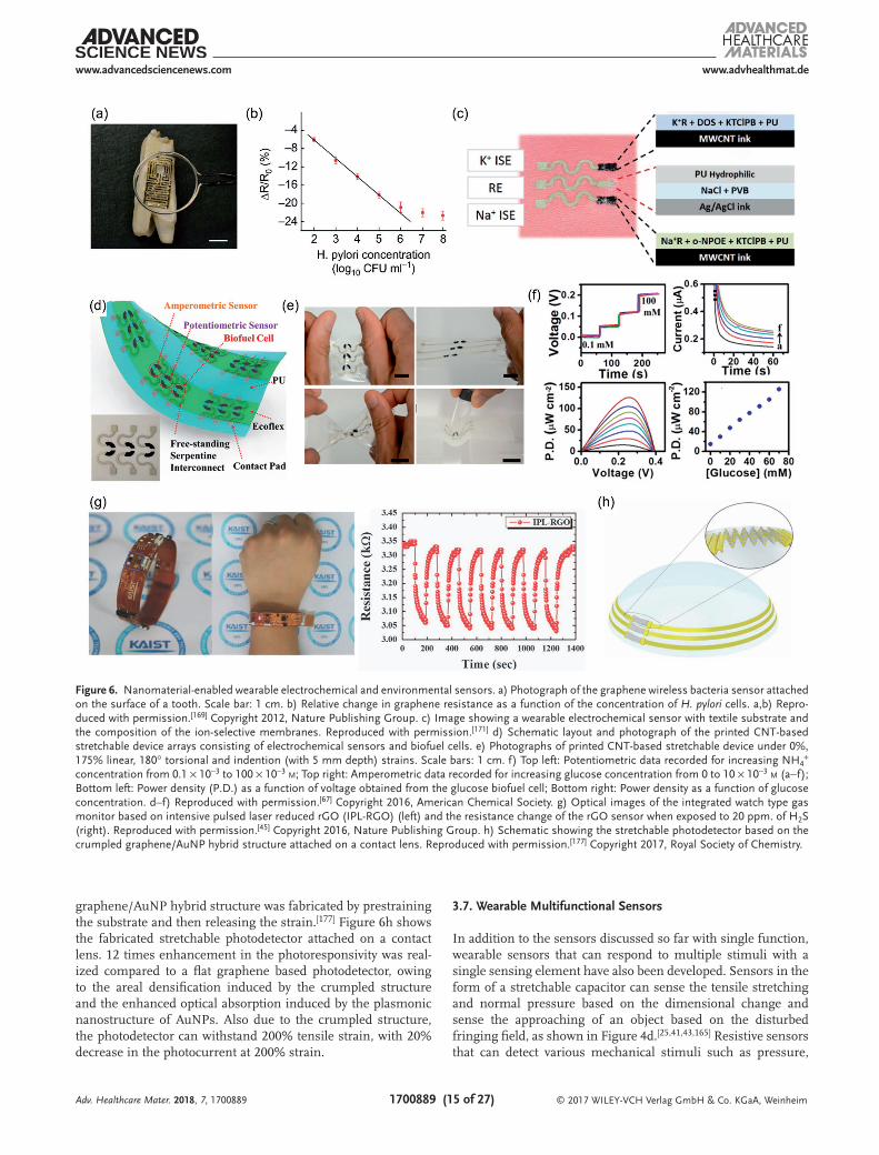
Going down to nanosize, nanomaterials offer a new oppor-tunity to improve the sensor performance (sensitivity, selec-tivity, stability, and reproducibility), as shown in Table 5. Carbon based nanomaterials received much attention due to its large specific surface area, presence of structural defects, high electric conductivity, high mechanical strength, and excel-lent chemical and thermal stability. For instance, graphene printed silk with interdigitated configuration was used as a biointerface sensing platform to target analytes (Figure 6a). The graphene silk was transferred to tooth enamel followed by functionalization with anti-microbial peptides for wireless monitoring of respiration, bacteria (Staphylococcus aureus), and selectively recognize Helicobacter pylori cells in saliva as shown in Figure 6b.[169] Significantly, the sensor achieved detection limit of 1 bacterium µL−1 for a range of 103–108 CFU mL−1 in wireless operation mode. Meanwhile, gold doped graphene and gold mesh enabled wearable patch (stretchability of ≈30%) was demonstrated for glucose sensing in the range of 10 × 10−6 to 0.7 × 10⁻³ m.[170] The graphene based biochemical sensor showed enhanced electrochemical activity for significant bio-markers in human sweat. While graphene and CNT as flexible materials are widely used in physical sensing as discussed in previous sections, they are still rarely employed in wearable chemical sensors so far.
Wang and co-workers underpinned the wearable technology with electrochemistry and opened a doorway to the new exciting sensing platforms, i.e., noninvasive on-body and on-site appli-cations in healthcare, sports and fitness. For instance, his team has developed a CNT printed textile based wearable electro-chemical sensor to detect electrolytes (sodium and potassium) in sweat.[171] In detail, stretchable components such as PU, eco-flex, and stretchable resistive inks (CNT and Ag/AgCl ink) were printed in a serpentine design array on a textile substrate and modified with ion selective membranes (Figure 6c). The sensor can withstand high tensile strain without showing any crack. The textile sensor was examined using open circuit potential measurements and a calibration curve recorded between the
Adv. Healthcare Mater. 2018, 7, 1700889

© 2017 WILEY-VCH Verlag GmbH & Co. KGaA, Weinheim1700889 (14 of 27)
www.advancedsciencenews.com www.advhealthmat.de
change in EMF and the time while changing the concentra-tion of NaCl and KCl solutions. The Nernstian response was 59.4 mV/log [Na+] for a linear range (10−4 to 10−1 m) with a detection limit 10−4.9 m for sodium selective electrode and 56.5 mV/log [K+] for a range 10−4 to 10−1 m with detection limit 10−4.9 m for the potassium selective electrode.
His team further built a CNT based electrochemical sensor and biofuel cell (BFC) that can endure strains as high as 500% with no effect on structural integrity and sensor performance (Figure 6d).[67] Electrochemical characterization of the device revealed that repeated strain (from 0% to 500%), torsional twisting (180° for 50 cycles) and indenting stress (5 mm depth for 50 repetitions) had negligible effect on its device properties as shown in Figure 6e. A CNT-based device func-tionalized with selective ionophores and enzymes was devel-oped to realize a wide-range of applications toward potentio-metric ammonium sensor ((0.1–100) × 10−3 m), amperometric enzyme based glucose sensor ((0–10) × 10−3 m), enzymatic glucose BFC and self-powered biosensor (Figure 6f). Another CNT-silver nanoink based BFCs with textile substrate were exploited as self-powered sensors that can harvest energy from perspiration for probing sweat metabolites (glucose and lactate).[66]
Dehydration can be a risk factor and symptoms for various diseases. To facilitate tracking of this health indicator in a wear-able form factor, our group has recently demonstrated the moni toring of skin humidity using a compliant AgNW/PDMS based interdigitated electrode.[42] The skin impedance between the two electrode decreases with the skin hydration level owing to the increased dielectric constant and conductivity of skin. The resulting skin hydration sensor is stretchable, low-cost and suitable for long-term hydration sensing.
3.6. Wearable Environmental Sensors
Wearable environmental sensors monitor the environmental parameters such as humidity, light illumination and gas concentration (Table 6). Such information can help protect human beings from hostile environment, provide insight into influence of the environment on the healthcare and
facilitate the interaction of human beings and robotics with the environment. For humidity sensing, both capacitive and resistive sensors have been reported. Change in humidity can affect the proton hopping and ionic conductivity of functional groups on graphene oxide, leading to increasing capacitance under higher humidity.[172] In a CNT based capacitive sensors, the presence of water vapors or other chemical solvents can enhance the fringing field of the sensor owing to the arrange-ment of dipoles from the water vapor or other solvents.[54] The amplitude of capacitance increase is related to the dipole moments of the solvents. In a CNT/poly(vinyl alcohol) (PVA) fiber based resistive sensors, high humidity level can swell the filament, decrease the intertube distance of CNTs and thus decrease the resistance of the CNT/PVA fibers.[55]
To track the gas concentration for personal wellness and security surveillance, wearable gas sensors based on gra-phene,[32] rGO,[45,173] ZnO NPs,[174] AgNW–graphene,[175] CNT/SnO2 NW hybrid film,[31] and polypyrrole NPs[176] were developed to detect the concentration of gases such as nitrogen dioxide (NO2),[31,32,173] ammonia (NH3),[176] hydrogen sulfide (H2S),[45] hydrogen (H2),[45] ethanol (C2H5OH),[45,174] acetic acid (CH3COOH),[176] dimethyl methylphosphonate (C3H9O3P, DMMP),[175] acetone (CH3COCH3),[175] meth-anol (CH3OH),[175] and tetradecane (C14H30).[175] Increase or decrease in resistance is typically detected, depending on whether the gaseous stimulus is an electron donator or an electron acceptor. For example, rGO was capable of detecting various gases including H2, H2S, and ethanol.[45] The sensor can be integrated into a watch-type wearable gas monitor, as shown in Figure 6g. Besides flexible gas sensors, stretchable gas sensors were also demonstrated by Lee et al.[173] Stable NO2 sensing performance under 30% strain was observed for rGO based gas sensors.
For wearable photodetectors, various materials such as crum-pled graphene-AuNPs,[177] ZnO nanostructures,[82,178,179] rGO/PVDF-TrFE nanocomposites,[180] MoS2/WS2 heterojunction arrays,[181] Zn2SnO4 NWs,[182] SnO2 NWs[31,183] were employed for the detection of UV,[31,82,178,179,182,183] infrared (IR),[180] or other light illumination,[177,181] based on the principle that light illumination can excite more electrons into the conduc-tion band generating photocurrent.[31] In particular, a crumpled
Adv. Healthcare Mater. 2018, 7, 1700889
Table 5. Summary of the performances of representative nanomaterial-enabled wearable electrochemical sensors reported.
Materials Analytes Biofluids Sensitivity Sensing range Detection limit Stretchability
Graphene printed
silk[169]
Staphylococcus
aureus
Saliva – 103–108 CFU mL−1 1 bacterium µL−1 –
Graphene doped
Au mesh[170]
Glucose, pH Sweat 1 µA mm−1 (glucose),
71.8 mV pH−1 (pH)
10 × 10−6 to 0.7 × 10⁻³ m
(glucose), 5–8 (pH)
10 × 10−6 m (glucose) 30%
CNT[171] Na+ and K+ Sweat 51.6 mV/log [K+],
51.8 mV/log [Na+]
(0.1–100) × 10−3 m
(both K+ and Na+)
10−4.9 m (both K+ and
Na+)
100%
CNT and Ag ink[66] Glucose and lactate Sweat 3.14 ± 0.2 µW cm−2 mm−1 (glucose),
6.71 ± 0.91 µW cm−2 mm−1 (lactate)
(0–50) × 10−3 m (glucose) and
(0–20) × 10−3 m (lactate)
0.3 × 10⁻³ m (lactate) 100%
CNT[67] NH4+ and glucose Sweat – (0.1–100) × 10−3 m (NH4
+) and
(0–10) × 10−3 m (glucose)
– 500%
CNT[199] Glucose, lactate,
Na+, and K+Sweat 2.35 nA µm−1 (glucose), 220 nA µm−1
(lactate), 64.2 mV dec−1 (Na+),
61.3 mV dec−1 (K+)
(0–200) × 10−6 m (glucose),
(2–30) × 10−3 m (lactate), (10–160) ×
10−3 m (Na+), (1–32) × 10−3 m (K+)
– –
© 2017 WILEY-VCH Verlag GmbH & Co. KGaA, Weinheim1700889 (15 of 27)
www.advancedsciencenews.com www.advhealthmat.de
graphene/AuNP hybrid structure was fabricated by prestraining the substrate and then releasing the strain.[177] Figure 6h shows the fabricated stretchable photodetector attached on a contact lens. 12 times enhancement in the photoresponsivity was real-ized compared to a flat graphene based photodetector, owing to the areal densification induced by the crumpled structure and the enhanced optical absorption induced by the plasmonic nanostructure of AuNPs. Also due to the crumpled structure, the photodetector can withstand 200% tensile strain, with 20% decrease in the photocurrent at 200% strain.
3.7. Wearable Multifunctional Sensors
In addition to the sensors discussed so far with single function, wearable sensors that can respond to multiple stimuli with a single sensing element have also been developed. Sensors in the form of a stretchable capacitor can sense the tensile stretching and normal pressure based on the dimensional change and sense the approaching of an object based on the disturbed fringing field, as shown in Figure 4d.[25,41,43,165] Resistive sensors that can detect various mechanical stimuli such as pressure,
Adv. Healthcare Mater. 2018, 7, 1700889
Figure 6. Nanomaterial-enabled wearable electrochemical and environmental sensors. a) Photograph of the graphene wireless bacteria sensor attached on the surface of a tooth. Scale bar: 1 cm. b) Relative change in graphene resistance as a function of the concentration of H. pylori cells. a,b) Repro-duced with permission.[169] Copyright 2012, Nature Publishing Group. c) Image showing a wearable electrochemical sensor with textile substrate and the composition of the ion-selective membranes. Reproduced with permission.[171] d) Schematic layout and photograph of the printed CNT-based stretchable device arrays consisting of electrochemical sensors and biofuel cells. e) Photographs of printed CNT-based stretchable device under 0%, 175% linear, 180° torsional and indention (with 5 mm depth) strains. Scale bars: 1 cm. f) Top left: Potentiometric data recorded for increasing NH4
+ concentration from 0.1 × 10⁻³ to 100 × 10−3 m; Top right: Amperometric data recorded for increasing glucose concentration from 0 to 10 × 10−3 m (a−f); Bottom left: Power density (P.D.) as a function of voltage obtained from the glucose biofuel cell; Bottom right: Power density as a function of glucose concentration. d–f) Reproduced with permission.[67] Copyright 2016, American Chemical Society. g) Optical images of the integrated watch type gas monitor based on intensive pulsed laser reduced rGO (IPL-RGO) (left) and the resistance change of the rGO sensor when exposed to 20 ppm. of H2S (right). Reproduced with permission.[45] Copyright 2016, Nature Publishing Group. h) Schematic showing the stretchable photodetector based on the crumpled graphene/AuNP hybrid structure attached on a contact lens. Reproduced with permission.[177] Copyright 2017, Royal Society of Chemistry.
© 2017 WILEY-VCH Verlag GmbH & Co. KGaA, Weinheim1700889 (16 of 27)
www.advancedsciencenews.com www.advhealthmat.de
stretching, bending, shear, torsion and acoustic vibration were also reported.[26,38,139,157,184] For example, the multifunctional sensor with interlocked microdome arrays (Figure 5a) exhibited a pressure sensitivity of 15.1 kPa−1,[141] a shear-force sensitivity of 2.21 N−1 under a normal pressure of 65 Pa and a ultrahigh sensitivity to tensile strain (i.e., 27.8 for strain of 0–40%, 1084 for 40–90%, and 9617 for 90–120%).[144] Figure 7a highlights a resistive sensor based on CNT coated foams with negative Poisson’s ratio (auxetic foams) for the detection of pressure, stretching, torsion and ultrasound acoustic wave.[48] The auxetic foams were able to shrink/stretch concurrently in three dimen-sions, and therefore enhanced the pressure sensitivity by 300% and tensile strain sensitivity by 500%.
Simultaneous sensing of temperature and pressure were demonstrated by utilizing piezoresistive and pyroelectric behavior of PVDF/ZnO NR nanocomposites[62] or piezo-electric and pyroelectric properties of PVDF-TrFE/BaTiO3 nanocomposites.[185] Concurrent sensing of temperature, mechanical parameters, and environmental parameters can also be realized. For example, stretchable ZnO NW-PU
composites enabled pyroelectric temperature sensing, resis-tive strain sensing, and UV illumination detection.[82] By assembling ligand coated AuNP sensing film on a self-healing polymer substrate, the resulting flexible platform allowed for resistive strain sensing, thermoresistive temperature sensing, and chemiresistive sensing of multiple volatile organic compounds (VOCs).[186] In another work, CNT microyarns were aligned with Ecoflex as the dielectric to form a grid of stretchable capacitive sensors (Figure 7b).[54] In addition to the capacitive sensing of pressure and finger approaching, the temperature variations can be detected due to thermore-sistive response of the CNT yarns, while the humidity and other chemical solvents can be detected from the capacitance change. In contrast to the finger approaching that leads to a decrease in capacitance, higher humidity level or higher con-centration of chemical solvents leads to an increase in capac-itance due to the existence of dipoles in the water or other chemical solvents.
Assembling sensors with multifunctionalities to achieve multimodal sensing could simplify the sensor integration.
Adv. Healthcare Mater. 2018, 7, 1700889
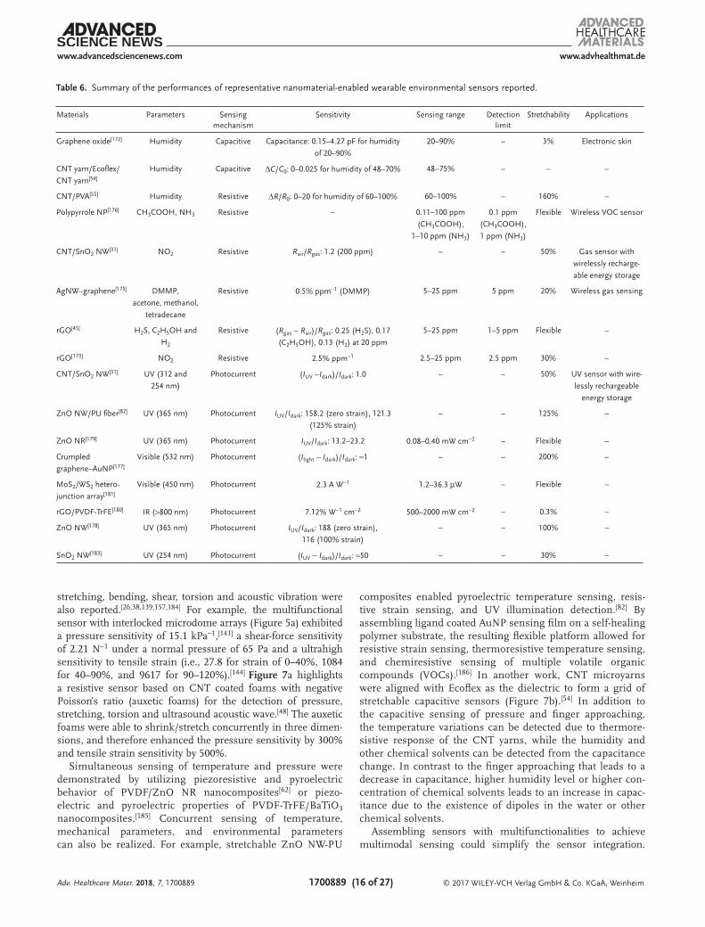
Table 6. Summary of the performances of representative nanomaterial-enabled wearable environmental sensors reported.
Materials Parameters Sensing mechanism
Sensitivity Sensing range Detection limit
Stretchability Applications
Graphene oxide[172] Humidity Capacitive Capacitance: 0.15–4.27 pF for humidity
of 20–90%
20–90% – 3% Electronic skin
CNT yarn/Ecoflex/
CNT yarn[54]
Humidity Capacitive ΔC/C0: 0–0.025 for humidity of 48–70% 48–75% – – –
CNT/PVA[55] Humidity Resistive ΔR/R0: 0–20 for humidity of 60–100% 60–100% – 160% –
Polypyrrole NP[176] CH3COOH, NH3 Resistive – 0.11–100 ppm
(CH3COOH),
1–10 ppm (NH3)
0.1 ppm
(CH3COOH),
1 ppm (NH3)
Flexible Wireless VOC sensor
CNT/SnO2 NW[31] NO2 Resistive Rair/Rgas: 1.2 (200 ppm) – – 50% Gas sensor with
wirelessly recharge-
able energy storage
AgNW–graphene[175] DMMP,
acetone, methanol,
tetradecane
Resistive 0.5% ppm−1 (DMMP) 5–25 ppm 5 ppm 20% Wireless gas sensing
rGO[45] H2S, C2H5OH and
H2
Resistive (Rgas − Rair)/Rgas: 0.25 (H2S), 0.17
(C2H5OH), 0.13 (H2) at 20 ppm
5–25 ppm 1–5 ppm Flexible –
rGO[173] NO2 Resistive 2.5% ppm−1 2.5–25 ppm 2.5 ppm 30% –
CNT/SnO2 NW[31] UV (312 and
254 nm)
Photocurrent (IUV −Idark)/Idark: 1.0 – – 50% UV sensor with wire-
lessly rechargeable
energy storage
ZnO NW/PU fiber[82] UV (365 nm) Photocurrent IUV/Idark: 158.2 (zero strain), 121.3
(125% strain)
– – 125% –
ZnO NR[179] UV (365 nm) Photocurrent IUV/Idark: 13.2–23.2 0.08–0.40 mW cm−2 – Flexible –
Crumpled
graphene–AuNP[177]
Visible (532 nm) Photocurrent (Ilight − Idark)/Idark: ≈1 – – 200% –
MoS2/WS2 hetero-
junction array[181]
Visible (450 nm) Photocurrent 2.3 A W−1 1.2–36.3 µW – Flexible –
rGO/PVDF-TrFE[180] IR (>800 nm) Photocurrent 7.12% W−1 cm−2 500–2000 mW cm−2 – 0.3% –
ZnO NW[178] UV (365 nm) Photocurrent IUV/Idark: 188 (zero strain),
116 (100% strain)
– – 100% –
SnO2 NW[183] UV (254 nm) Photocurrent (IUV − Idark)/Idark: ≈50 – – 30% –

© 2017 WILEY-VCH Verlag GmbH & Co. KGaA, Weinheim1700889 (17 of 27)
www.advancedsciencenews.com www.advhealthmat.de
However, different functions may affect each other, especially when multistimuli are coexisting. For instance, in a capaci-tive sensor, multiple stimuli can cause capacitance change, including tensile stretching (capacitance increase), normal pres-sure (capacitance increase), finger approaching (capacitance decrease), and humidity level change (capacitance increase or decrease).[25,41] It is challenging to tell from the measured capacitance change alone which stimuli are present and the contribution of each stimulus. Similar challenges exist for mul-tifunctional resistive sensors in response to multiple stimuli. Efforts have been made to differentiate and decouple individual responses. In order to discern the pressing, stretching, bending and sound vibration from the output signals, a stacked struc-ture composed of both resistive and capacitive sensing ele-ments were employed (Figure 5d).[131] The resistance changes in top and bottom electrodes indicated the frequency, direction and amplitude of the strain, and the capacitance change in the capacitor indicated the frequency and amplitude of the strain and pressure. The stimuli can be identified from the patterns of the two resistance signals and one capacitance signal. The
output signal patterns for repetitive bending and pressing are illustrated in Figure 7c as examples.[131] In spite of these efforts, challenges related to quantifying the response for each stim-ulus still remain and should be further addressed for concur-rent multimodal sensing.
4. Integrated Wearable Systems
Wearable sensors with different sensing capabilities can be monolithically integrated to achieve multimodal sensing. Wear-able sensors can also be integrated with other components to enable advanced wearable applications. For instance, actuators or stimulators may be incorporated to achieve interactive devices that can interact with human body, another device or the envi-ronment.[22,37,170,187] Drug-delivery platforms can be integrated to enable therapeutic treatments in response to the information collected by the wearable sensors.[188–190] Energy scavengers could negate the need for frequently charging batteries or com-pletely replace the batteries.[191–193] Data acquisition, storage,
Adv. Healthcare Mater. 2018, 7, 1700889
Figure 7. Nanomaterial-enabled wearable multifunctional sensors and integration of multiple sensors for multimodal sensing. a) Relative resistance change with respect to stretching and compression for sensors based on conventional foam (ν = 0.4) and auxetic foam (ν = −0.5). Reproduced with permission.[48] b) Schematic illustration of the stretchable capacitive multifunctional sensors based on CNT yarns. Reproduced with permission.[54] c) Relative capacitance change (blue circles), relative resistance change of the top electrode (black diamonds) and bottom electrode (red triangles) as a function of time when the CNT based sensor was under repetitive bending (top) and pressing (bottom). Reproduced with permission.[131] d) Image of the electronic skin with fingerprint-like structures for temperature, tactile and slip-force detection (top). Enlarged image of one pixel comprising four strain sensors and a temperature sensor (bottom). Reproduced with permission.[196] Copyright 2014, American Chemical Society. e) Schematic illustra-tion of the epidermal device containing serpentine-shaped temperature and strain sensors (left) and images of the device attached on human skin (right).[197] f) Schematic diagram showing the integration of multimodal all-graphene sensor array consisting of resistive temperature sensors (rGO), capacitive humidity sensors (GO), and capacitive pressure sensors (two graphene electrodes sandwiched by PDMS). Reproduced with permission.[172] g) Schematic of a ligands functionalized AuNP sensor array for VOC detection and heart beat/breath rate sensing. Reproduced with permission.[198] Copyright 2016, American Chemical Society.
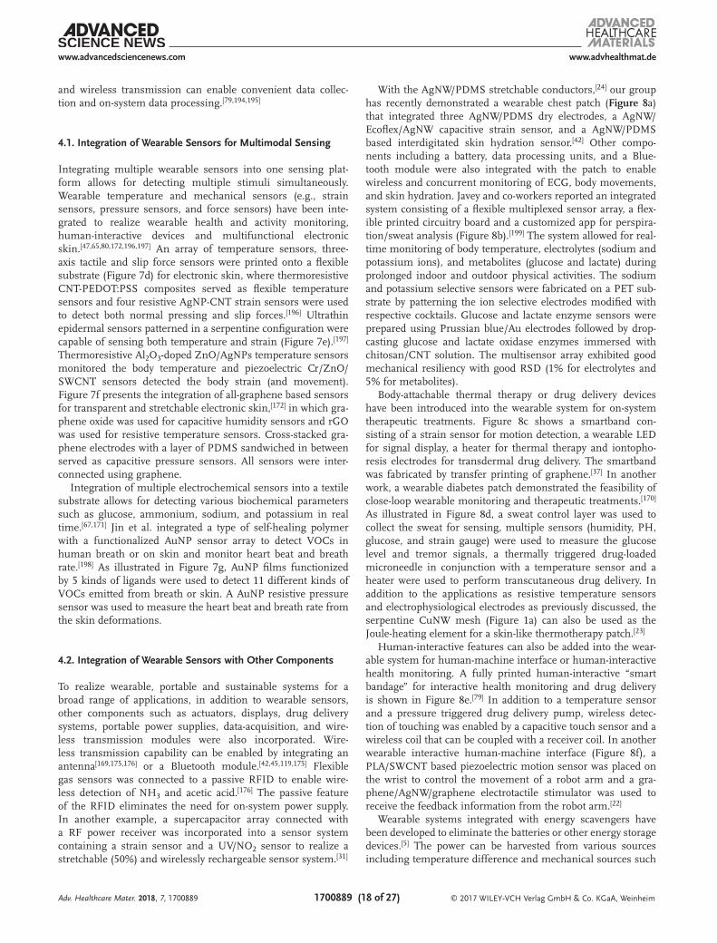
© 2017 WILEY-VCH Verlag GmbH & Co. KGaA, Weinheim1700889 (18 of 27)
www.advancedsciencenews.com www.advhealthmat.de
and wireless transmission can enable convenient data collec-tion and on-system data processing.[79,194,195]
4.1. Integration of Wearable Sensors for Multimodal Sensing
Integrating multiple wearable sensors into one sensing plat-form allows for detecting multiple stimuli simultaneously. Wearable temperature and mechanical sensors (e.g., strain sensors, pressure sensors, and force sensors) have been inte-grated to realize wearable health and activity monitoring, human-interactive devices and multifunctional electronic skin.[47,65,80,172,196,197] An array of temperature sensors, three-axis tactile and slip force sensors were printed onto a flexible substrate (Figure 7d) for electronic skin, where thermoresistive CNT-PEDOT:PSS composites served as flexible temperature sensors and four resistive AgNP-CNT strain sensors were used to detect both normal pressing and slip forces.[196] Ultrathin epidermal sensors patterned in a serpentine configuration were capable of sensing both temperature and strain (Figure 7e).[197] Thermoresistive Al2O3-doped ZnO/AgNPs temperature sensors monitored the body temperature and piezoelectric Cr/ZnO/SWCNT sensors detected the body strain (and movement). Figure 7f presents the integration of all-graphene based sensors for transparent and stretchable electronic skin,[172] in which gra-phene oxide was used for capacitive humidity sensors and rGO was used for resistive temperature sensors. Cross-stacked gra-phene electrodes with a layer of PDMS sandwiched in between served as capacitive pressure sensors. All sensors were inter-connected using graphene.
Integration of multiple electrochemical sensors into a textile substrate allows for detecting various biochemical parameters such as glucose, ammonium, sodium, and potassium in real time.[67,171] Jin et al. integrated a type of self-healing polymer with a functionalized AuNP sensor array to detect VOCs in human breath or on skin and monitor heart beat and breath rate.[198] As illustrated in Figure 7g, AuNP films functionized by 5 kinds of ligands were used to detect 11 different kinds of VOCs emitted from breath or skin. A AuNP resistive pressure sensor was used to measure the heart beat and breath rate from the skin deformations.
4.2. Integration of Wearable Sensors with Other Components
To realize wearable, portable and sustainable systems for a broad range of applications, in addition to wearable sensors, other components such as actuators, displays, drug delivery systems, portable power supplies, data-acquisition, and wire-less transmission modules were also incorporated. Wire-less transmission capability can be enabled by integrating an antenna[169,175,176] or a Bluetooth module.[42,45,119,175] Flexible gas sensors was connected to a passive RFID to enable wire-less detection of NH3 and acetic acid.[176] The passive feature of the RFID eliminates the need for on-system power supply. In another example, a supercapacitor array connected with a RF power receiver was incorporated into a sensor system containing a strain sensor and a UV/NO2 sensor to realize a stretchable (50%) and wirelessly rechargeable sensor system.[31]
With the AgNW/PDMS stretchable conductors,[24] our group has recently demonstrated a wearable chest patch (Figure 8a) that integrated three AgNW/PDMS dry electrodes, a AgNW/Ecoflex/AgNW capacitive strain sensor, and a AgNW/PDMS based interdigitated skin hydration sensor.[42] Other compo-nents including a battery, data processing units, and a Blue-tooth module were also integrated with the patch to enable wireless and concurrent monitoring of ECG, body movements, and skin hydration. Javey and co-workers reported an integrated system consisting of a flexible multiplexed sensor array, a flex-ible printed circuitry board and a customized app for perspira-tion/sweat analysis (Figure 8b).[199] The system allowed for real-time monitoring of body temperature, electrolytes (sodium and potassium ions), and metabolites (glucose and lactate) during prolonged indoor and outdoor physical activities. The sodium and potassium selective sensors were fabricated on a PET sub-strate by patterning the ion selective electrodes modified with respective cocktails. Glucose and lactate enzyme sensors were prepared using Prussian blue/Au electrodes followed by drop-casting glucose and lactate oxidase enzymes immersed with chitosan/CNT solution. The multisensor array exhibited good mechanical resiliency with good RSD (1% for electrolytes and 5% for metabolites).
Body-attachable thermal therapy or drug delivery devices have been introduced into the wearable system for on-system therapeutic treatments. Figure 8c shows a smartband con-sisting of a strain sensor for motion detection, a wearable LED for signal display, a heater for thermal therapy and iontopho-resis electrodes for transdermal drug delivery. The smartband was fabricated by transfer printing of graphene.[37] In another work, a wearable diabetes patch demonstrated the feasibility of close-loop wearable monitoring and therapeutic treatments.[170] As illustrated in Figure 8d, a sweat control layer was used to collect the sweat for sensing, multiple sensors (humidity, PH, glucose, and strain gauge) were used to measure the glucose level and tremor signals, a thermally triggered drug-loaded microneedle in conjunction with a temperature sensor and a heater were used to perform transcutaneous drug delivery. In addition to the applications as resistive temperature sensors and electrophysiological electrodes as previously discussed, the serpentine CuNW mesh (Figure 1a) can also be used as the Joule-heating element for a skin-like thermotherapy patch.[23]
Human-interactive features can also be added into the wear-able system for human-machine interface or human-interactive health monitoring. A fully printed human-interactive “smart bandage” for interactive health monitoring and drug delivery is shown in Figure 8e.[79] In addition to a temperature sensor and a pressure triggered drug delivery pump, wireless detec-tion of touching was enabled by a capacitive touch sensor and a wireless coil that can be coupled with a receiver coil. In another wearable interactive human-machine interface (Figure 8f), a PLA/SWCNT based piezoelectric motion sensor was placed on the wrist to control the movement of a robot arm and a gra-phene/AgNW/graphene electrotactile stimulator was used to receive the feedback information from the robot arm.[22]
Wearable systems integrated with energy scavengers have been developed to eliminate the batteries or other energy storage devices.[5] The power can be harvested from various sources including temperature difference and mechanical sources such
Adv. Healthcare Mater. 2018, 7, 1700889

© 2017 WILEY-VCH Verlag GmbH & Co. KGaA, Weinheim1700889 (19 of 27)
www.advancedsciencenews.com www.advhealthmat.de
as body movements and vibrations.[66,67,75,131,133,162,200,201] In an effort toward self-powered sensors, a sensor structure shown in Figure 5d was used as a triboelectric nanogenerator (TENG).[131] Power can be generated from various mechanical stimuli such as pressing, stretching, twisting, and sound driven vibrations due to the change in the air gap. Self-powered pressure sensors were achieved by incorporating a TENG with a capacitor as the energy storage device.[162] Figure 8g highlights the integration of a strain sensor, a stretchable supercapacitor, and a TENG into one platform.[201] Conductive, stretchable, and transparent
nanocomposites of AgNW/PEDOT:PSS/PU were used as the resistive sensing elements for strain sensors and the conduc-tive electrodes for the supercapacitors and triboelectric energy harvesters. Transmittance of 75.3%, strain sensing range up to 60% and ultralow power consumption of 5 µW cm−2 were realized. The low power consumption made it feasible for the strain sensors to be powered by the integrated nanogenerator and supercapacitor. In order to realize fully self-powered wear-able systems, more efforts should be made to develop wearable energy generators with high power generation capacity.[6,202]
Adv. Healthcare Mater. 2018, 7, 1700889
Figure 8. Integration of wearable sensors with other components. a) AgNW/PDMS based wearable chest patch for concurrent and wireless monitoring of ECG, body movements and skin hydration. Reproduced with permission.[42] b) Photograph of the sensor array with flexible and wireless print circuitry board on wrist (left). Schematic illustration of the integrated sensor array consisting of glucose, lactate, sodium, potassium, and temperature sensors for multiplexed perspiration analysis (right). Reproduced with permission.[199] Copyright 2016, Nature Publishing Group. c) Schematic diagram of the smartband consisting a strain sensor, signal display, thermal physiotherapy (by a thermal actuator) and transdermal drug delivery (by iontophoresis electrodes). Reproduced with permission.[37] d) Schematic of the wearable diabetes patch with sweat collecting, electrochemical sensing and transcu-taneous drug delivery enabled by a thermal responsive microneedle array. Reproduced with permission.[170] Copyright 2016, Nature Publishing Group. e) Schematic of a human-interactive device consisting of a capacitive touch sensor array, a temperature sensor, a wireless coil and a drug delivery pump. Reproduced with permission.[79] f) A closed loop actuation system for interactive robot control that contains a piezoelectric motion sensor and an electrotactile stimulator placed on the wrist and a pressure sensor attached on the robot arm.[22] g) Schematics showing the device architecture of the stretchable and transparent resistive strain sensor, stretchable supercapacitor, and triboelectric nanogenerator (left). SEM image of the AgNW/PEDOT:PSS/PU nanocomposite film (top right) and image of the vertically integrated device (bottom right). Reproduced with permission.[201] Copyright 2015, American Chemical Society.
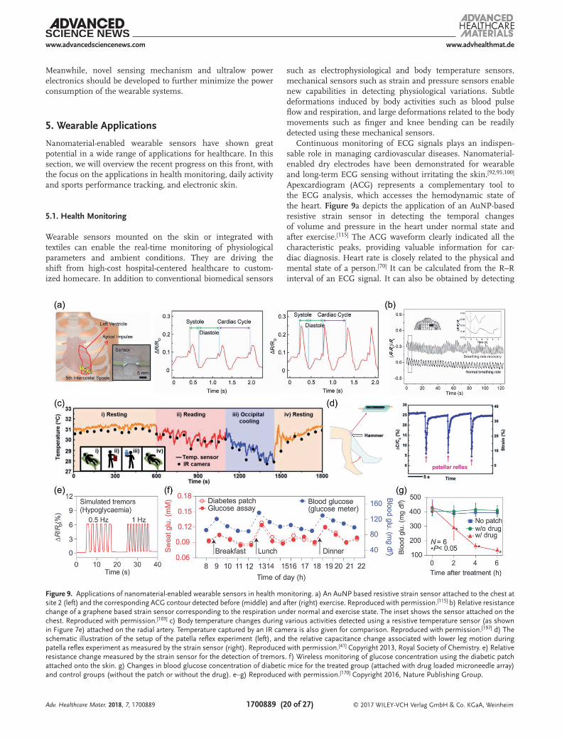
© 2017 WILEY-VCH Verlag GmbH & Co. KGaA, Weinheim1700889 (20 of 27)
www.advancedsciencenews.com www.advhealthmat.de
Meanwhile, novel sensing mechanism and ultralow power electronics should be developed to further minimize the power consumption of the wearable systems.
5. Wearable Applications
Nanomaterial-enabled wearable sensors have shown great potential in a wide range of applications for healthcare. In this section, we will overview the recent progress on this front, with the focus on the applications in health monitoring, daily activity and sports performance tracking, and electronic skin.
5.1. Health Monitoring
Wearable sensors mounted on the skin or integrated with textiles can enable the real-time monitoring of physiological parameters and ambient conditions. They are driving the shift from high-cost hospital-centered healthcare to custom-ized homecare. In addition to conventional biomedical sensors
such as electrophysiological and body temperature sensors, mechanical sensors such as strain and pressure sensors enable new capabilities in detecting physiological variations. Subtle deformations induced by body activities such as blood pulse flow and respiration, and large deformations related to the body movements such as finger and knee bending can be readily detected using these mechanical sensors.
Continuous monitoring of ECG signals plays an indispen-sable role in managing cardiovascular diseases. Nanomaterial-enabled dry electrodes have been demonstrated for wearable and long-term ECG sensing without irritating the skin.[92,95,100] Apexcardiogram (ACG) represents a complementary tool to the ECG analysis, which accesses the hemodynamic state of the heart. Figure 9a depicts the application of an AuNP-based resistive strain sensor in detecting the temporal changes of volume and pressure in the heart under normal state and after exercise.[115] The ACG waveform clearly indicated all the characteristic peaks, providing valuable information for car-diac diagnosis. Heart rate is closely related to the physical and mental state of a person.[70] It can be calculated from the R–R interval of an ECG signal. It can also be obtained by detecting
Adv. Healthcare Mater. 2018, 7, 1700889
Figure 9. Applications of nanomaterial-enabled wearable sensors in health monitoring. a) An AuNP based resistive strain sensor attached to the chest at site 2 (left) and the corresponding ACG contour detected before (middle) and after (right) exercise. Reproduced with permission.[115] b) Relative resistance change of a graphene based strain sensor corresponding to the respiration under normal and exercise state. The inset shows the sensor attached on the chest. Reproduced with permission.[103] c) Body temperature changes during various activities detected using a resistive temperature sensor (as shown in Figure 7e) attached on the radial artery. Temperature captured by an IR camera is also given for comparison. Reproduced with permission.[197] d) The schematic illustration of the setup of the patella reflex experiment (left), and the relative capacitance change associated with lower leg motion during patella reflex experiment as measured by the strain sensor (right). Reproduced with permission.[41] Copyright 2013, Royal Society of Chemistry. e) Relative resistance change measured by the strain sensor for the detection of tremors. f) Wireless monitoring of glucose concentration using the diabetic patch attached onto the skin. g) Changes in blood glucose concentration of diabetic mice for the treated group (attached with drug loaded microneedle array) and control groups (without the patch or without the drug). e–g) Reproduced with permission.[170] Copyright 2016, Nature Publishing Group.
© 2017 WILEY-VCH Verlag GmbH & Co. KGaA, Weinheim1700889 (21 of 27)
www.advancedsciencenews.com www.advhealthmat.de
Adv. Healthcare Mater. 2018, 7, 1700889
the strain or pressure induced by radial artery waves at the wrist or finger tip,[44,57,59,103,120,123,126,139,203] jugular venous pulses at the neck[57,59,151] or ankle brachial artery pulses near the foot.[21] Monitoring of respiration rate is critical in diagnosis of many disorders or diseases such as sleep disorders, asthma and anemia.[70] It can be accessed by measuring the deforma-tion associated with respiration using wearable strain[103,120,121] or pressure sensors[57] placed on the chest, or by measuring the pressure caused by the air flow using a pressure sensor placed under the nose.[141] As an example, Figure 9b gives the output signals of a graphene based resistive strain sensor (attached on the chest) corresponding to the respiration under normal state and after exercise.[103] The respiration rate can also be obtained by monitoring the temperature change caused by mouth res-piration or nose breathing.[82] As another important vital sign, body temperature can be monitored continuously using inte-grated wearable systems.[79,197] For instance, a temperature sensor based on Al2O3-doped ZnO/AgNPs (Figure 7e) was attached onto the skin on the radial artery.[197] Temperature variations during various activities including resting, reading a book and occipital cooling were monitored for the detection of hypothermia, as shown in Figure 9c.
Monitoring of body motions is beneficial in evaluating body functions. Abnormal body motions can be symptoms of many diseases such as Parkinson’s disease, epilepsy, and stroke. AgNW based strain sensors attached to the knee were used to monitor the lower leg motion during a patella reflex experi-ment, as shown in Figure 9d.[41] The amplitude and duration of the knee motion recorded by the capacitance change of the sensor can provide important information for early diagnosis of nervous system diseases.
In an advanced wearable system with both sensing and ther-apeutic treatment capabilities,[37,79,170] highly sensitive multi-modal sensors can monitor the physiological parameters to evaluate health conditions or monitor body motions to access the effectiveness of rehabilitation. The real-time data can be sent wirelessly to the wearer, a caregiver, or an emergency center. Once abnormal conditions are noticed, an alarm will be sent. Proper guidance will be given from the caregiver, such as orally taking medications, going to the hospital for further treatment or performing therapeutic treatments using on-system therapy or drug delivery components. In a graphene based wearable system comprising a strain sensor, a wearable LED, a heater and iontophoresis electrodes (Figure 8c), when tremor signals were detected by the strain sensor, the wearable LED alarmed the user about abnormal conditions.[37] In response, the heater can provide the temperature for thermal therapy and the ionto-phoresis electrodes can trigger the transdermal drug delivery. In a wearable diabetes patch consisting of multiple wearable sensors, a sweat collection system and a microneedle array, as shown previously in Figure 8d, the tremor signals under hypo-glycemic conditions can be measured by a strain sensor and the sweat can be collected for glucose sensing.[170] Figure 9e illustrates the capability of the integrated strain sensor for the detection of simulated tremor signals in vitro. Figure 9f shows in vivo wireless monitoring of glucose via the integrated Blue-tooth module. In response to the measured glucose level, tem-perature controlled drug release can be achieved by heating the microneedle array to trigger the drug release through the
microneedles. Figure 9g shows successful blood glucose regula-tion of diabetic mice with the microneedle array attached near the abdomen.
5.2. Daily Activity and Sports Performance Tracking
Analysis of daily and sports activities can provide valuable insights into well-being and fitness of human beings, impor-tant feedback during rehabilitation, and quantitative data for evaluation of athletic performances. Such information can also be used to develop novel human–machine interfaces.
Wearable strain sensors with a large strain detection range are widely used to monitor body motions, including finger bending,[41,52,120,123,126] forearm muscle move-ments,[21,44,52,103,120,123,153] and knee motions.[41,121,153] Figure 10a highlights a CNT based strain sensor used for detection of various knee motions during extending, flexing, marching, squatting, and jumping.[121] Both intensity and frequency of the motions can be identified. The phonation vibrations and voice patterns can be monitored using a strain sensor[44,52,103,120,121,123,126] or a pressure sensor[57,141] attached to the neck. An example using a carbonized silk nanofiber based pressure sensor is given in Figure 10b.[57] Recognizing emotional expressions such as laughing,[46] crying,[46] blinking eyes,[46,103] and others[44,46,103,123] has been realized by using strain sensors to monitor the associated skin movements. Figure 10c shows the skin movements on the forehead and near the mouth during laughing and crying as examples.[46] Pressure sensors can also be attached onto the hand to monitor the pressure distribution during grabbing an object.[158] Heart rate, respiration rate, body motions, and other para meters collected from wearable sensors can provide crucial information to evaluate and improve the performances during rehabilitation or sports.
Simultaneous and continuous monitoring of sweat profile during exercise can be conducted using wearable electrochem-ical sensors.[66,199] As illustrated in Figure 10d, by wearing the device consisting of a multiplexed sensor array and a flexible printed circuitry board in the form of a wristband or headband, variations of skin temperature, electrolytes, and sweat metabo-lites in perspiration can be monitored wirelessly using a cus-tomized app on a smart phone.[199] The sweat analysis enabled real-time assessment of the physiological and metabolic state and provided important information for disease diagnosis and athletic performance evaluation.
5.3. Electronic Skin for Prosthetics and Intelligent Robotics
A network of wearable sensors can be mounted onto the sur-face of prosthetics or robots to mimic the sensory and trans-duction capabilities of natural human skin. The mechanically compliant sensor-laden electronic skin renders the capability to detect changes in the surrounding environment.[13,204] The ability to sense the environment can benefit the interaction with the environment, which is especially important when the robotic system is performing tasks in a hostile environ-ment. Successful mimicking of human skin requires good

© 2017 WILEY-VCH Verlag GmbH & Co. KGaA, Weinheim1700889 (22 of 27)
www.advancedsciencenews.com www.advhealthmat.de
Adv. Healthcare Mater. 2018, 7, 1700889
mechanical compliance, high sensitivity, good spatiotemporal resolution, and multimodal sensing capability.[20]
A multitude of pressure sensing arrays have been demon-strated to capture the spatial pressure distributions induced by different sources, such as a static object placed onto the sensing array,[57,139,141,158,203] gas flow,[141,144,153] bouncing of a water droplet (Figure 11a),[139] finger touch,[144,161] and acoustic vibra-tion.[144,203] Besides the pressure sensors, strain sensors were used to detect the movement of a cricket and sound signals.[123] Integration of these sensors with transistors can enable active matrix addressing. Each pixel is actively controlled by a tran-sistor, realizing mapping of external stimuli with low crosstalk
between adjacent signals.[30,84,85,134] For example, as shown in Figure 11b, an active matrix electronic skin consisting of strain sensors based on piezopotential-gated graphene transistors was able to capture the spatial distribution of strain.[134]
Electronic skin that is capable of detecting multiple stimuli has also been developed. Temperature and tactile mapping can be achieved by integrating temperature sensors and tac-tile sensors into a single pixel.[62,65] An electronic skin with all graphene based temperature, humidity, and pressure sensors integrated, shown in Figure 7f, was able to detect changes in temperature, humidity and pressure during hot wind blowing, hand touching and breathing.[172] Figure 11c,d presents the
Figure 10. Applications of nanomaterial-enabled wearable sensors in daily activity and sports performance tracking. a) Various human motions monitored by a CNT based resistive strain sensor placed on the knee. Reproduced with permission.[121] Copyright 2011, Nature Publishing Group. b) Recognition of sound signals by attaching a carbonized silk nanofiber enabled pressure sensor on the neck. Reproduced with permission.[57] c) Relative resistance change of a SWCNT/PEDOT: PSS strain sensor attached to the forehead when the subject was laughing (left) and near the mouth when the subject was crying (right). Reproduced with permission.[46] Copyright 2015, American Chemical Society. d) Photograph showing the real-time perspiration analysis using a smart headband and a smart wristband during cycling (left). Variations in body temperature and glucose, lactate, sodium, potassium concentrations as measured by the headband during 150 W cycling. Reproduced with permission.[199] Copyright 2016, Nature Publishing Group.
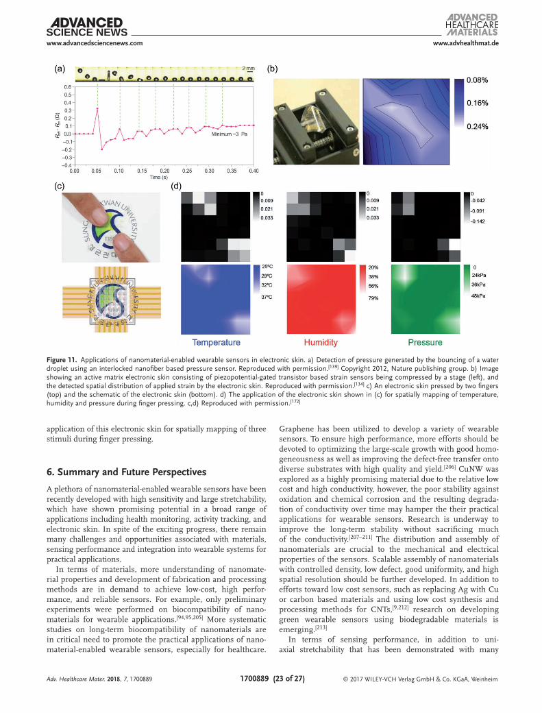
© 2017 WILEY-VCH Verlag GmbH & Co. KGaA, Weinheim1700889 (23 of 27)
www.advancedsciencenews.com www.advhealthmat.de
Adv. Healthcare Mater. 2018, 7, 1700889
application of this electronic skin for spatially mapping of three stimuli during finger pressing.
6. Summary and Future Perspectives
A plethora of nanomaterial-enabled wearable sensors have been recently developed with high sensitivity and large stretchability, which have shown promising potential in a broad range of applications including health monitoring, activity tracking, and electronic skin. In spite of the exciting progress, there remain many challenges and opportunities associated with materials, sensing performance and integration into wearable systems for practical applications.
In terms of materials, more understanding of nanomate-rial properties and development of fabrication and processing methods are in demand to achieve low-cost, high perfor-mance, and reliable sensors. For example, only preliminary experiments were performed on biocompatibility of nano-materials for wearable applications.[94,95,205] More systematic studies on long-term biocompatibility of nanomaterials are in critical need to promote the practical applications of nano-material-enabled wearable sensors, especially for healthcare.
Graphene has been utilized to develop a variety of wearable sensors. To ensure high performance, more efforts should be devoted to optimizing the large-scale growth with good homo-geneousness as well as improving the defect-free transfer onto diverse substrates with high quality and yield.[206] CuNW was explored as a highly promising material due to the relative low cost and high conductivity, however, the poor stability against oxidation and chemical corrosion and the resulting degrada-tion of conductivity over time may hamper the their practical applications for wearable sensors. Research is underway to improve the long-term stability without sacrificing much of the conductivity.[207–211] The distribution and assembly of nanomaterials are crucial to the mechanical and electrical properties of the sensors. Scalable assembly of nanomaterials with controlled density, low defect, good uniformity, and high spatial resolution should be further developed. In addition to efforts toward low cost sensors, such as replacing Ag with Cu or carbon based materials and using low cost synthesis and processing methods for CNTs,[9,212] research on developing green wearable sensors using biodegradable materials is emerging.[213]
In terms of sensing performance, in addition to uni-axial stretchability that has been demonstrated with many
Figure 11. Applications of nanomaterial-enabled wearable sensors in electronic skin. a) Detection of pressure generated by the bouncing of a water droplet using an interlocked nanofiber based pressure sensor. Reproduced with permission.[139] Copyright 2012, Nature publishing group. b) Image showing an active matrix electronic skin consisting of piezopotential-gated transistor based strain sensors being compressed by a stage (left), and the detected spatial distribution of applied strain by the electronic skin. Reproduced with permission.[134] c) An electronic skin pressed by two fingers (top) and the schematic of the electronic skin (bottom). d) The application of the electronic skin shown in (c) for spatially mapping of temperature, humidity and pressure during finger pressing. c,d) Reproduced with permission.[172]
© 2017 WILEY-VCH Verlag GmbH & Co. KGaA, Weinheim1700889 (24 of 27)
www.advancedsciencenews.com www.advhealthmat.de
Adv. Healthcare Mater. 2018, 7, 1700889
nanomaterial-enabled wearable sensors, more efforts should be devoted to achieving multiaxial stretchability. Dynamic, multi-axial motions such as facial movements and rotation of joints are ubiquitous in daily activities. Extensive focus has been placed on improving the sensitivity and stretchability of wear-able sensors; however, to ensure continuous wearable appli-cations, long-term stability of the sensing performance and attachment onto skin (adhesion) under cyclic multiaxial strain should be improved.
In terms of integration of sensors into wearable systems, one of the challenges is cross-sensitivity of different sensors. One sensor may respond to multiple stimuli, making it dif-ficult to identify the exact type of stimuli and the intensity of each stimulus. Studies on novel sensing mechanisms with low cross-sensitivity and efficient algorithms to decouple the stimuli should be conducted. In addition, most of the reported nanomaterial-based devices are relative large or have limited spatial resolution, which makes the integration of multiple sensors into a single platform challenging. Advances in low-cost, high resolution, high rate, and scalable patterning and integration techniques are in great need to realize spatial mapping or multimodal sensing. Another challenge is associ-ated with the heterogeneous integration of flexible/stretchable wearable sensors with other, typically stiffer, components such as displays, data processing and transmission units, super-capacitors, drug delivery components, energy harvesters, or batteries. Poor interfaces between the wearable sensors and these other components often occur due to the dissimilar elec-trical/mechanical/thermal properties. Cracking and delamina-tion under repetitive mechanical deformations may happen, leading to device failure. More fundamental understanding of interfacial mechanics, novel structural designs and improved synthesis and processing methods with well-controlled proper-ties and assembly are required. Developing these components with improved compliance and stretchability[29,189,193,214–216] can facilitate their integration with wearable sensors. In addi-tion, low-power electronics and high efficient energy genera-tors are desirable for the development of self-powered wear-able systems.
Technological advances in the fabrication and processing of nanomaterials, high-performance wearable sensors (e.g., with good biocompatibility, reliable multimodal sensing capabilities, stable sensing performance under multiaxial strain), efficient integration techniques, together with the progress on other flexible/stretchable components will promote further growth of the field and facilitate increasing applications of the nanomate-rial-enabled advanced wearable systems.
AcknowledgementsThe authors gratefully acknowledge the financial support from the National Science Foundation (NSF) through Award No. IIS-1637892.
Conflict of InterestThe authors declare no conflict of interest.
Keywordsactivity tracking, electronic skin, health monitoring, nanomaterials, wearable sensors
Received: July 26, 2017Revised: September 17, 2017
Published online: November 30, 2017
[1] Wearable Electronic Devices Market—Global Industry Analysis, Size, Share, Trends and Forecast, 2015–2023, Infinium Global Research, Bopodi Pune, India 2017.
[2] I. Korhonen, J. Parkka, M. Van Gils, IEEE Eng. Med. Biol. Mag. 2003, 22, 66.
[3] S. C. Mukhopadhyay, IEEE Sens. J 2015, 15, 1321.[4] M. M. Rodgers, V. M. Pai, R. S. Conroy, IEEE Sens. J 2015, 15, 3119.[5] J. Dieffenderfer, H. Goodell, S. Mills, M. McKnight, S. Yao,
F. Lin, E. Beppler, B. Bent, B. Lee, V. Misra, Y. Zhu, O. Oralkan, J. Strohmaier, J. Muth, D. Peden, A. Bozkurt, IEEE J. Biomed. Health Inform. 2016, 20, 1251.
[6] T. Q. Trung, N. E. Lee, Adv. Mater. 2016, 28, 4338.[7] D.-H. Kim, N. Lu, R. Ma, Y.-S. Kim, R.-H. Kim, S. Wang, J. Wu,
S. M. Won, H. Tao, A. Islam, K. J. Yu, T.-i. Kim, R. Chowdhury, M. Ying, L. Xu, M. Li, H.-J. Chung, H. Keum, M. McCormick, P. Liu, Y.-W. Zhang, F. G. Omenetto, Y. Huang, T. Coleman, J. A. Rogers, Science 2011, 333, 838.
[8] R. C. Webb, A. P. Bonifas, A. Behnaz, Y. Zhang, K. J. Yu, H. Cheng, M. Shi, Z. Bian, Z. Liu, Y.-S. Kim, W.-H. Yeo, J. S. Park, J. Song, Y. Li, Y. Huang, A. M. Gorbach, J. A. Rogers, Nat. Mater. 2013, 12, 938.
[9] C. Choi, M. K. Choi, T. Hyeon, D. H. Kim, ChemNanoMat 2016, 2, 1006.
[10] G. Pike, C. Seager, Phys. Rev. B 1974, 10, 1421.[11] S. Kirkpatrick, Rev. Mod. Phys. 1973, 45, 574.[12] L. Hu, H. Wu, Y. Cui, MRS Bull. 2011, 36, 760.[13] J. C. Yeo, C. T. Lim, Microsyst. Nanoeng. 2016, 2, 16043.[14] W. Weng, P. Chen, S. He, X. Sun, H. Peng, Angew. Chem., Int. Ed.
2016, 55, 6140.[15] C. S. Boland, U. Khan, G. Ryan, S. Barwich, R. Charifou, A. Harvey,
C. Backes, Z. Li, M. S. Ferreira, M. E. Möbius, Science 2016, 354, 1257.
[16] Y. Kim, J. Zhu, B. Yeom, M. Di Prima, X. Su, J.-G. Kim, S. J. Yoo, C. Uher, N. A. Kotov, Nature 2013, 500, 59.
[17] N. Matsuhisa, D. Inoue, P. Zalar, H. Jin, Y. Matsuba, A. Itoh, T. Yokota, D. Hashizume, T. Someya, Nat. Mater. 2017, 16, 834.
[18] S. Yao, Y. Zhu, Adv. Mater. 2015, 27, 1480.[19] S. Gong, W. Cheng, Adv. Electron. Mater. 2017, 3, 1600314.[20] M. L. Hammock, A. Chortos, B. C. K. Tee, J. B. H. Tok, Z. Bao, Adv.
Mater. 2013, 25, 5997.[21] N. N. Jason, S. J. Wang, S. Bhanushali, W. Cheng, Nanoscale 2016,
8, 16596.[22] S. Lim, D. Son, J. Kim, Y. B. Lee, J. K. Song, S. Choi, D. J. Lee,
J. H. Kim, M. Lee, T. Hyeon, D.-H. Kim, Adv. Funct. Mater. 2015, 25, 375.
[23] S. Han, M. K. Kim, B. Wang, D. S. Wie, S. Wang, C. H. Lee, Adv. Mater. 2016, 28, 10257.
[24] F. Xu, Y. Zhu, Adv. Mater. 2012, 24, 5117.[25] D. J. Lipomi, M. Vosgueritchian, B. C. Tee, S. L. Hellstrom,
J. A. Lee, C. H. Fox, Z. Bao, Nat. Nanotechnol. 2011, 6, 788.[26] S. Jung, J. H. Kim, J. Kim, S. Choi, J. Lee, I. Park, T. Hyeon,
D. H. Kim, Adv. Mater. 2014, 26, 4825.[27] H. Chen, Z. Su, Y. Song, X. Cheng, X. Chen, B. Meng, Z. Song,
D. Chen, H. Zhang, Adv. Funct. Mater. 2016, 27, 1604434.

© 2017 WILEY-VCH Verlag GmbH & Co. KGaA, Weinheim1700889 (25 of 27)
www.advancedsciencenews.com www.advhealthmat.de
Adv. Healthcare Mater. 2018, 7, 1700889
[28] Y. Pang, H. Tian, L. Tao, Y. Li, X. Wang, N. Deng, Y. Yang, T.-L. Ren, ACS Appl. Mater. Interfaces 2016, 8, 26458.
[29] T. Q. Trung, N. E. Lee, Adv. Mater. 2017, 29, 1603167.[30] S. Y. Hong, Y. H. Lee, H. Park, S. W. Jin, Y. R. Jeong, J. Yun, I. You,
G. Zi, J. S. Ha, Adv. Mater. 2016, 28, 930.[31] D. Kim, D. Kim, H. Lee, Y. R. Jeong, S. J. Lee, G. Yang, H. Kim,
G. Lee, S. Jeon, G. Zi, J. Kim, J. S. Ha, Adv. Mater. 2016, 28, 748.[32] J. Yun, Y. Lim, G. N. Jang, D. Kim, S.-J. Lee, H. Park, S. Y. Hong,
G. Lee, G. Zi, J. S. Ha, Nano Energy 2016, 19, 401.[33] S. Zhao, J. Li, D. Cao, G. Zhang, J. Li, K. Li, Y. Yang, W. Wang, Y. Jin,
R. Sun, C.-P. Wong, ACS Appl. Mater. Interfaces 2017, 9, 12147.[34] J. A. Rogers, T. Someya, Y. Huang, Science 2010, 327, 1603.[35] K. Xie, B. Wei, Adv. Mater. 2014, 26, 3592.[36] Q. Sun, D. H. Kim, S. S. Park, N. Y. Lee, Y. Zhang, J. H. Lee,
K. Cho, J. H. Cho, Adv. Mater. 2014, 26, 4735.[37] M. K. Choi, I. Park, D. C. Kim, E. Joh, O. K. Park, J. Kim, M. Kim,
C. Choi, J. Yang, K. W. Cho, J.-H. Hwang, J.-M. Nam, T. Hyeon, J. H. Kim, D.-H. Kim, Adv. Funct. Mater. 2015, 25, 7109.
[38] M. Park, Y. J. Park, X. Chen, Y. K. Park, M. S. Kim, J. H. Ahn, Adv. Mater. 2016, 28, 2556.
[39] S. J. Park, J. Kim, M. Chu, M. Khine, Adv. Mater. Technol. 2016, 1, 1600053.
[40] S. Y. Chung, H.-J. Lee, T. I. Lee, Y. S. Kim, RSC Adv. 2017, 7, 2520.[41] S. Yao, Y. Zhu, Nanoscale 2014, 6, 2345.[42] S. Yao, A. Myers, A. Malhotra, F. Lin, A. Bozkurt, J. F. Muth,
Y. Zhu, Adv. Healthcare Mater. 2017, 6, 1601159.[43] W. Hu, X. Niu, R. Zhao, Q. Pei, Appl. Phys. Lett. 2013, 102, 38.[44] S. Gong, D. T. Lai, B. Su, K. J. Si, Z. Ma, L. W. Yap, P. Guo,
W. Cheng, Adv. Electron. Mater. 2015, 1, 1400063.[45] S.-J. Choi, S.-J. Kim, I.-D. Kim, NPG Asia Mater. 2016, 8, e315.[46] E. Roh, B.-U. Hwang, D. Kim, B.-Y. Kim, N.-E. Lee, ACS Nano
2015, 9, 6252.[47] T. Q. Trung, S. Ramasundaram, B. U. Hwang, N. E. Lee, Adv.
Mater. 2016, 28, 502.[48] Y. Li, S. Luo, M. C. Yang, R. Liang, C. Zeng, Adv. Funct. Mater.
2016, 26, 2900.[49] C. Yan, J. Wang, P. S. Lee, ACS Nano 2015, 9, 2130.[50] K. K. Kim, S. Hong, H. M. Cho, J. Lee, Y. D. Suh, J. Ham, S. H. Ko,
Nano Lett. 2015, 15, 5240.[51] C. Yan, J. Wang, W. Kang, M. Cui, X. Wang, C. Y. Foo, K. J. Chee,
P. S. Lee, Adv. Mater. 2014, 26, 2022.[52] J. J. Park, W. J. Hyun, S. C. Mun, Y. T. Park, O. O. Park, ACS Appl.
Mater. Interfaces 2015, 7, 6317.[53] S. Ryu, P. Lee, J. B. Chou, R. Xu, R. Zhao, A. J. Hart, S.-G. Kim,
ACS Nano 2015, 9, 5929.[54] S. Y. Kim, S. Park, H. W. Park, D. H. Park, Y. Jeong, D. H. Kim, Adv.
Mater. 2015, 27, 4178.[55] G. Zhou, J.-H. Byun, Y. Oh, B.-M. Jung, H.-J. Cha, D.-G. Seong,
M.-K. Um, S. Hyun, T.-W. Chou, ACS Appl. Mater. Interfaces 2017, 9, 4788.
[56] M. Park, J. Im, M. Shin, Y. Min, J. Park, H. Cho, S. Park, M.-B. Shim, S. Jeon, D.-Y. Chung, J. Bae, J. Park, U. Jeong, K. Kim, Nat. Nanotechnol. 2012, 7, 803.
[57] Q. Wang, M. Jian, C. Wang, Y. Zhang, Adv. Funct. Mater. 2017, 27, 1605657.
[58] L. Persano, C. Dagdeviren, Y. Su, Y. Zhang, S. Girardo, D. Pisignano, Y. Huang, J. A. Rogers, Nat. Commun. 2013, 4, 1633.
[59] S.-H. Park, H. B. Lee, S. M. Yeon, J. Park, N. K. Lee, ACS Appl. Mater. Interfaces 2016, 8, 24773.
[60] H. Cui, M. Nowicki, J. P. Fisher, L. G. Zhang, Adv. Healthcare Mater. 2017, 6, 1601118.
[61] K. Fukuda, T. Someya, Adv. Mater. 2017, 29, 1602736.[62] J. S. Lee, K.-Y. Shin, O. J. Cheong, J. H. Kim, J. Jang, Sci. Rep. 2015,
5, 7887.
[63] W. Lee, H. Koo, J. Sun, J. Noh, K.-S. Kwon, C. Yeom, Y. Choi, K. Chen, A. Javey, G. Cho, Sci. Rep. 2014, 5, 17707.
[64] C. Yeom, K. Chen, D. Kiriya, Z. Yu, G. Cho, A. Javey, Adv. Mater. 2015, 27, 1561.
[65] K. Kanao, S. Harada, Y. Yamamoto, W. Honda, T. Arie, S. Akita, K. Takei, RSC Adv. 2015, 5, 30170.
[66] I. Jeerapan, J. R. Sempionatto, A. Pavinatto, J.-M. You, J. Wang, J. Mater. Chem. A 2016, 4, 18342.
[67] A. J. Bandodkar, I. Jeerapan, J.-M. You, R. Nuñez-Flores, J. Wang, Nano Lett. 2015, 16, 721.
[68] S. Gong, D. T. Lai, Y. Wang, L. W. Yap, K. J. Si, Q. Shi, N. N. Jason, T. Sridhar, H. Uddin, W. Cheng, ACS Appl. Mater. Interfaces 2015, 7, 19700.
[69] S. Z. Guo, K. Qiu, F. Meng, S. H. Park, M. C. McAlpine, Adv. Mater. 2017, 29, 1701218.
[70] Y. Khan, A. E. Ostfeld, C. M. Lochner, A. Pierre, A. C. Arias, Adv. Mater. 2015, 28, 4373.
[71] K. Takei, W. Honda, S. Harada, T. Arie, S. Akita, Adv. Healthcare Mater. 2015, 4, 487.
[72] Q. Li, L. N. Zhang, X. M. Tao, X. Ding, Adv. Healthcare Mater. 2017, 6, 1601371.
[73] Q. Li, L. N. Zhang, X. M. Tao, X. Ding, Adv. Healthcare Mater. 2017, 6, 1601371.
[74] H. Jin, Y. S. Abu-Raya, H. Haick, Adv. Healthcare Mater. 2017, 6, 1700024.
[75] R. Bendi, V. Bhavanasi, K. Parida, V. C. Nguyen, A. Sumboja, K. Tsukagoshi, P. S. Lee, Nano Energy 2016, 26, 586.
[76] D. Kong, L. T. Le, Y. Li, J. L. Zunino, W. Lee, Langmuir 2012, 28, 13467.
[77] T. Q. Trung, S. Ramasundaram, S. W. Hong, N. E. Lee, Adv. Funct. Mater. 2014, 24, 3438.
[78] J. Yang, D. Wei, L. Tang, X. Song, W. Luo, J. Chu, T. Gao, H. Shi, C. Du, RSC Adv. 2015, 5, 25609.
[79] W. Honda, S. Harada, T. Arie, S. Akita, K. Takei, Adv. Funct. Mater. 2014, 24, 3299.
[80] S. Harada, W. Honda, T. Arie, S. Akita, K. Takei, ACS Nano 2014, 8, 3921.
[81] H. Yang, D. Qi, Z. Liu, B. K. Chandran, T. Wang, J. Yu, X. Chen, Adv. Mater. 2016, 28, 9175.
[82] X. Liao, Q. Liao, Z. Zhang, X. Yan, Q. Liang, Q. Wang, M. Li, Y. Zhang, Adv. Funct. Mater. 2016.
[83] C. Hou, H. Wang, Q. Zhang, Y. Li, M. Zhu, Adv. Mater. 2014, 26, 5018.
[84] C. Wang, D. Hwang, Z. Yu, K. Takei, J. Park, T. Chen, B. Ma, A. Javey, Nat. Mater. 2013, 12, 899.
[85] K. Takei, T. Takahashi, J. C. Ho, H. Ko, A. G. Gillies, P. W. Leu, R. S. Fearing, A. Javey, Nat. Mater. 2010, 9, 821.
[86] J. Webster, Medical Instrumentation: Application and Design, John Wiley & Sons, Hoboken, NJ 2009.
[87] S. Yao, Y. Zhu, JOM 2016, 68, 1145.[88] S. J. Kim, K. W. Cho, H. R. Cho, L. Wang, S. Y. Park, S. E. Lee,
T. Hyeon, N. Lu, S. H. Choi, D. H. Kim, Adv. Funct. Mater. 2016, 26, 3207.
[89] S. Yang, Y. C. Chen, L. Nicolini, P. Pasupathy, J. Sacks, B. Su, R. Yang, D. Sanchez, Y. F. Chang, P. Wang, D. Schnyer, D. Neikirk, N. Lu, Adv. Mater. 2015, 27, 6423.
[90] W. Klimesch, Brain Res. Rev. 1999, 29, 169.[91] A. Searle, L. Kirkup, Physiol. Meas. 2000, 21, 271.[92] A. C. Myers, H. Huang, Y. Zhu, RSC Adv. 2015, 5, 11627.[93] P. Mostafalu, S. Sonkusale, RSC Adv. 2015, 5, 8680.[94] H.-C. Jung, J.-H. Moon, D.-H. Baek, J.-H. Lee, Y.-Y. Choi,
J.-S. Hong, S.-H. Lee, IEEE Trans. Biomed. Eng. 2012, 59, 1472.
[95] S. M. Lee, H. J. Byeon, J. H. Lee, D. H. Baek, K. H. Lee, J. S. Hong, S.-H. Lee, Sci. Rep. 2014, 4, 6074.
© 2017 WILEY-VCH Verlag GmbH & Co. KGaA, Weinheim1700889 (26 of 27)
www.advancedsciencenews.com www.advhealthmat.de
Adv. Healthcare Mater. 2018, 7, 1700889
[96] S. M. Lee, J. H. Kim, C. Park, J.-Y. Hwang, J. S. Hong, K. H. Lee, S. H. Lee, IEEE Trans. Biomed. Eng. 2016, 63, 138.
[97] M. K. Kwak, H. E. Jeong, K. Y. Suh, Adv. Mater. 2011, 23, 3949.[98] N. Meziane, J. Webster, M. Attari, A. Nimunkar, Physiol. Meas.
2013, 34, R47.[99] J. W. Jeong, M. K. Kim, H. Cheng, W. H. Yeo, X. Huang, Y. Liu,
Y. Zhang, Y. Huang, J. A. Rogers, Adv. Healthcare Mater. 2014, 3, 642.
[100] T. Kim, J. Park, J. Sohn, D. Cho, S. Jeon, ACS Nano 2016, 10, 4770.[101] J. Park, I. You, S. Shin, U. Jeong, ChemPhysChem 2015, 16, 1155.[102] J.-S. Noh, Polymers 2016, 8, 123.[103] Y. Wang, L. Wang, T. Yang, X. Li, X. Zang, M. Zhu, K. Wang, D. Wu,
H. Zhu, Adv. Funct. Mater. 2014, 24, 4666.[104] S. Beeby, G. Ensell, M. Kraft, N. White, MEMS Mechanical Sensors,
Artech House, Norwood, MA 2004.[105] J. Zhao, C. He, R. Yang, Z. Shi, M. Cheng, W. Yang, G. Xie,
D. Wang, D. Shi, G. Zhang, Appl. Phys. Lett. 2012, 101, 063112.[106] N. Hu, H. Fukunaga, S. Atobe, Y. Liu, J. Li, Sensors 2011, 11, 10691.[107] M. Amjadi, K. U. Kyung, I. Park, M. Sitti, Adv. Funct. Mater. 2016,
26, 1678.[108] J. Zhao, K. Dai, C. Liu, G. Zheng, B. Wang, C. Liu, J. Chen, C. Shen,
Composites, Part A 2013, 48, 129.[109] L. Lin, S. Liu, Q. Zhang, X. Li, M. Ji, H. Deng, Q. Fu, ACS Appl.
Mater. Interfaces 2013, 5, 5815.[110] C. Lee, L. Jug, E. Meng, Appl. Phys. Lett. 2013, 102, 183511.[111] M. Amjadi, A. Pichitpajongkit, S. Lee, S. Ryu, I. Park, ACS Nano
2014, 8, 5154.[112] J. Lee, S. Kim, J. Lee, D. Yang, B. C. Park, S. Ryu, I. Park, Nanoscale
2014, 6, 11932.[113] H. Tian, Y. Shu, Y.-L. Cui, W.-T. Mi, Y. Yang, D. Xie, T.-L. Ren,
Nanoscale 2014, 6, 699.[114] S. Lee, M. Amjadi, N. Pugno, I. Park, S. Ryu, AIP Adv. 2015, 5,
117233.[115] I. You, B. Kim, J. Park, K. Koh, S. Shin, S. Jung, U. Jeong, Adv.
Mater. 2016, 28, 6359.[116] S. Huang, Y. Liu, C. F. Guo, Z. Ren, Adv. Electron. Mater. 2017, 3,
1600534.[117] G. Cai, J. Wang, K. Qian, J. Chen, S. Li, P. S. Lee, Adv. Sci. 2016, 4,
1600190.[118] H. Zhu, X. Wang, J. Liang, H. Lv, H. Tong, L. Ma, Y. Hu, G. Zhu,
T. Zhang, Z. Tie, Z. Liu, Q. Li, L. Chen, J. Liu, Z. Jin, Adv. Funct. Mater. 2017, 27, 1606604.
[119] T. Lee, W. Lee, S. W. Kim, J. J. Kim, B. S. Kim, Adv. Funct. Mater. 2016, 26, 6206.
[120] C. S. Boland, U. Khan, C. Backes, A. O’Neill, J. McCauley, S. Duane, R. Shanker, Y. Liu, I. Jurewicz, A. B. Dalton, J. N. Coleman, ACS Nano 2014, 8, 8819.
[121] T. Yamada, Y. Hayamizu, Y. Yamamoto, Y. Yomogida, A. Izadi-Najafabadi, D. N. Futaba, K. Hata, Nat. Nanotechnol. 2011, 6, 296.
[122] J. Zhou, H. Yu, X. Xu, F. Han, G. Lubineau, ACS Appl. Mater. Inter-faces 2017, 9, 4835.
[123] G. Shi, Z. Zhao, J. H. Pai, I. Lee, L. Zhang, C. Stevenson, K. Ishara, R. Zhang, H. Zhu, J. Ma, Adv. Funct. Mater. 2016, 26, 7614.
[124] X. Li, R. Zhang, W. Yu, K. Wang, J. Wei, D. Wu, A. Cao, Z. Li, Y. Cheng, Q. Zheng, R. S. Ruoff, H. Zhu, Sci. Rep. 2012, 2, 870.
[125] Y. R. Jeong, H. Park, S. W. Jin, S. Y. Hong, S. S. Lee, J. S. Ha, Adv. Funct. Mater. 2015, 25, 4228.
[126] Q. Liu, J. Chen, Y. Li, G. Shi, ACS Nano 2016, 10, 7901.[127] D. J. Cohen, D. Mitra, K. Peterson, M. M. Maharbiz, Nano Lett.
2012, 12, 1821.[128] S.-J. Woo, J.-H. Kong, D.-G. Kim, J.-M. Kim, J. Mater. Chem. C
2014, 2, 4415.[129] L. Cai, L. Song, P. Luan, Q. Zhang, N. Zhang, Q. Gao, D. Zhao,
X. Zhang, M. Tu, F. Yang, Sci. Rep. 2013, 3, 3048.
[130] U.-H. Shin, D.-W. Jeong, S.-M. Park, S.-H. Kim, H. W. Lee, J.-M. Kim, Carbon 2014, 80, 396.
[131] S. Park, H. Kim, M. Vosgueritchian, S. Cheon, H. Kim, J. H. Koo, T. R. Kim, S. Lee, G. Schwartz, H. Chang, Z. Bao, Adv. Mater. 2014, 26, 7324.
[132] W. Zhang, R. Zhu, V. Nguyen, R. Yang, Sens. Actuators, A 2014, 205, 164.
[133] E. Nour, C. O. Chey, M. Willander, O. Nur, Nanotechnology 2015, 26, 095502.
[134] Q. Sun, W. Seung, B. J. Kim, S. Seo, S. W. Kim, J. H. Cho, Adv. Mater. 2015, 27, 3411.
[135] S.-H. Bae, Y. Lee, B. K. Sharma, H.-J. Lee, J.-H. Kim, J.-H. Ahn, Carbon 2013, 51, 236.
[136] M. Amjadi, Y. J. Yoon, I. Park, Nanotechnology 2015, 26, 375501.[137] H. Lee, D. Kwon, H. Cho, I. Park, J. Kim, Sci. Rep. 2017, 7, 39837.[138] B. Nie, S. Xing, J. D. Brandt, T. Pan, Lab Chip 2012, 12, 1110.[139] C. Pang, G.-Y. Lee, T.-i. Kim, S. M. Kim, H. N. Kim, S.-H. Ahn,
K.-Y. Suh, Nat. Mater. 2012, 11, 795.[140] H. Tian, Y. Shu, X.-F. Wang, M. A. Mohammad, Z. Bie, Q.-Y. Xie,
C. Li, W.-T. Mi, Y. Yang, T.-L. Ren, Sci. Rep. 2015, 5, 8603.[141] J. Park, Y. Lee, J. Hong, M. Ha, Y.-D. Jung, H. Lim, S. Y. Kim, H. Ko,
ACS Nano 2014, 8, 4689.[142] M. Ha, S. Lim, J. Park, D. S. Um, Y. Lee, H. Ko, Adv. Funct. Mater.
2015, 25, 2841.[143] H. Park, Y. R. Jeong, J. Yun, S. Y. Hong, S. Jin, S.-J. Lee, G. Zi,
J. S. Ha, ACS Nano 2015, 9, 9974.[144] J. Park, Y. Lee, J. Hong, Y. Lee, M. Ha, Y. Jung, H. Lim, S. Y. Kim,
H. Ko, ACS Nano 2014, 8, 12020.[145] S. Lee, A. Reuveny, J. Reeder, S. Lee, H. Jin, Q. Liu, T. Yokota,
T. Sekitani, T. Isoyama, Y. Abe, Z. Suo, T. Someya, Nat. Nano-technol. 2016, 11, 472.
[146] S. Chun, H. Jung, Y. Choi, G. Bae, J. P. Kil, W. Park, Carbon 2015, 94, 982.
[147] X. Wang, Y. Gu, Z. Xiong, Z. Cui, T. Zhang, Adv. Mater. 2014, 26, 1336.
[148] B. Zhu, Z. Niu, H. Wang, W. R. Leow, H. Wang, Y. Li, L. Zheng, J. Wei, F. Huo, X. Chen, Small 2014, 10, 3625.
[149] G. Y. Bae, S. W. Pak, D. Kim, G. Lee, D. H. Kim, Y. Chung, K. Cho, Adv. Mater. 2016, 28, 5300.
[150] H. B. Yao, J. Ge, C. F. Wang, X. Wang, W. Hu, Z. J. Zheng, Y. Ni, S. H. Yu, Adv. Mater. 2013, 25, 6692.
[151] Y. Si, X. Wang, C. Yan, L. Yang, J. Yu, B. Ding, Adv. Mater. 2016, 28, 9512.
[152] B. You, C. J. Han, Y. Kim, B.-K. Ju, J.-W. Kim, J. Mater. Chem. A 2016, 4, 10435.
[153] J. Wang, J. Jiu, M. Nogi, T. Sugahara, S. Nagao, H. Koga, P. He, K. Suganuma, Nanoscale 2015, 7, 2926.
[154] S. C. Mannsfeld, B. C. Tee, R. M. Stoltenberg, C. V. H. Chen, S. Barman, B. V. Muir, A. N. Sokolov, C. Reese, Z. Bao, Nat. Mater. 2010, 9, 859.
[155] Y. Quan, X. Wei, L. Xiao, T. Wu, H. Pang, T. Liu, W. Huang, S. Wu, S. Li, Z. Chen, J. Alloy Compd. 2017, 699, 824.
[156] T. Li, H. Luo, L. Qin, X. Wang, Z. Xiong, H. Ding, Y. Gu, Z. Liu, T. Zhang, Small 2016, 12, 5042.
[157] D. Kwon, T.-I. Lee, J. Shim, S. Ryu, M. S. Kim, S. Kim, T.-S. Kim, I. Park, ACS Appl. Mater. Interfaces 2016, 8, 16922.
[158] Y. Joo, J. Byun, N. Seong, J. Ha, H. Kim, S. Kim, T. Kim, H. Im, D. Kim, Y. Hong, Nanoscale 2015, 7, 6208.
[159] W. Wu, X. Wen, Z. L. Wang, Science 2013, 340, 952.[160] L. Lin, Y. Xie, S. Wang, W. Wu, S. Niu, X. Wen, Z. L. Wang, ACS
Nano 2013, 7, 8266.[161] U. Khan, T. H. Kim, H. Ryu, W. Seung, S. W. Kim, Adv. Mater. 2017,
29, 1603544.[162] J. Luo, F. R. Fan, T. Zhou, W. Tang, F. Xue, Z. L. Wang, Extreme
Mech. Lett. 2015, 2, 28.

© 2017 WILEY-VCH Verlag GmbH & Co. KGaA, Weinheim1700889 (27 of 27)
www.advancedsciencenews.com www.advhealthmat.de
Adv. Healthcare Mater. 2018, 7, 1700889
[163] P. Bai, G. Zhu, Q. Jing, J. Yang, J. Chen, Y. Su, J. Ma, G. Zhang, Z. L. Wang, Adv. Funct. Mater. 2014, 24, 5807.
[164] G. Zhu, W. Q. Yang, T. Zhang, Q. Jing, J. Chen, Y. S. Zhou, P. Bai, Z. L. Wang, Nano Lett. 2014, 14, 3208.
[165] Y. Cheng, R. Wang, H. Zhai, J. Sun, Nanoscale 2017, 9, 3834.[166] Z. Cui, F. R. Poblete, G. Cheng, S. Yao, X. Jiang, Y. Zhu, J. Mater.
Res. 2015, 30, 79.[167] A. J. Bandodkar, J. Wang, Trends Biotechnol. 2014, 32, 363.[168] A. J. Bandodkar, D. Molinnus, O. Mirza, T. Guinovart,
J. R. Windmiller, G. Valdés-Ramírez, F. J. Andrade, M. J. Schöning, J. Wang, Biosens. Bioelectron. 2014, 54, 603.
[169] M. S. Mannoor, H. Tao, J. D. Clayton, A. Sengupta, D. L. Kaplan, R. R. Naik, N. Verma, F. G. Omenetto, M. C. McAlpine, Nat. Commun. 2012, 3, 763.
[170] H. Lee, T. K. Choi, Y. B. Lee, H. R. Cho, R. Ghaffari, L. Wang, H. J. Choi, T. D. Chung, N. Lu, T. Hyeon, S. H. Choi, D.-H. Kim, Nat. Nanotechnol. 2016, 11, 566.
[171] M. Parrilla, R. Cánovas, I. Jeerapan, F. J. Andrade, J. Wang, Adv. Healthcare Mater. 2016, 5, 996.
[172] D. H. Ho, Q. Sun, S. Y. Kim, J. T. Han, D. H. Kim, J. H. Cho, Adv. Mater. 2016, 28, 2601.
[173] H. B. Lee, C. W. Bae, L. T. Duy, I. Y. Sohn, D. I. Kim, Y. J. Song, Y. J. Kim, N. E. Lee, Adv. Mater. 2016, 28, 3069.
[174] Z. Zheng, J. Yao, B. Wang, G. Yang, Sci. Rep. 2015, 5, 11070[175] J. Park, J. Kim, K. Kim, S.-Y. Kim, W. H. Cheong, K. Park, J. H. Song,
G. Namgoong, J. J. Kim, J. Heo, F. Bien, J.-U. Park, Nanoscale 2016, 8, 10591.
[176] J. Jun, J. Oh, D. H. Shin, S. G. Kim, J. S. Lee, W. Kim, J. Jang, ACS Appl. Mater. Interfaces 2016, 8, 33139.
[177] M. Kim, P. Kang, J. Leem, S. Nam, Nanoscale 2017, 9, 4058.[178] C. Yan, J. Wang, X. Wang, W. Kang, M. Cui, C. Y. Foo, P. S. Lee,
Adv. Mater. 2014, 26, 943.[179] D.-K. Kwon, S. J. Lee, J.-M. Myoung, Nanoscale 2016, 8, 16677.[180] T. Q. Trung, S. Ramasundaram, N. E. Lee, Adv. Funct. Mater. 2015,
25, 1745.[181] Y. Xue, Y. Zhang, Y. Liu, H. Liu, J. Song, J. Sophia, J. Liu, Z. Xu,
Q. Xu, Z. Wang, J. Zheng, Y. Liu, S. Li, Q. Bao, ACS Nano 2015, 10, 573.
[182] J. Wang, C. Yan, W. Kang, P. S. Lee, Nanoscale 2014, 6, 10734.[183] J. Yoon, S. Y. Hong, Y. Lim, S. J. Lee, G. Zi, J. S. Ha, Adv. Mater.
2014, 26, 6580.[184] J. Zhou, X. Xu, H. Yu, G. Lubineau, Nanoscale 2017, 9, 604.[185] N. T. Tien, S. Jeon, D. I. Kim, T. Q. Trung, M. Jang, B. U. Hwang,
K. E. Byun, J. Bae, E. Lee, J. B. H. Tok, Z. Bao, N.-E. Lee, J.-J. Park, Adv. Mater. 2014, 26, 796.
[186] T. P. Huynh, H. Haick, Adv. Mater. 2016, 28, 138.[187] S. Yao, J. Cui, Z. Cui, Y. Zhu, Nanoscale 2017, 9, 3797.[188] J. Di, S. Yao, Y. Ye, Z. Cui, J. Yu, T. K. Ghosh, Y. Zhu, Z. Gu, ACS
Nano 2015, 9, 9407.[189] Y. Zhang, J. Yu, Y. Zhu, Z. Gu, Nanomedicine 2016, 11, 323.[190] Y. Zhang, J. Yu, H. N. Bomba, Y. Zhu, Z. Gu, Chem. Rev. 2016, 116,
12536.[191] W. Seung, M. K. Gupta, K. Y. Lee, K.-S. Shin, J.-H. Lee, T. Y. Kim,
S. Kim, J. Lin, J. H. Kim, S.-W. Kim, ACS Nano 2015, 9, 3501.
[192] S. Jung, J. Lee, T. Hyeon, M. Lee, D. H. Kim, Adv. Mater. 2014, 26, 6329.
[193] F. R. Fan, W. Tang, Z. L. Wang, Adv. Mater. 2016, 28, 4283.[194] F. Lin, S. Yao, M. McKnight, Y. Zhu, A. Bozkurt, in 2016 Conf. on
Biomedical Wireless Technologies, Networks, and Sensing Systems (BioWireleSS), Austin, TX, January 2016.
[195] L. Song, A. C. Myers, J. J. Adams, Y. Zhu, ACS Appl. Mater. Inter-faces 2014, 6, 4248.
[196] S. Harada, K. Kanao, Y. Yamamoto, T. Arie, S. Akita, K. Takei, ACS Nano 2014, 8, 12851.
[197] M. Park, K. Do, J. Kim, D. Son, J. H. Koo, J. Park, J. K. Song, J. H. Kim, M. Lee, T. Hyeon, D.-H. Kim, Adv. Healthcare Mater. 2015, 4, 992.
[198] H. Jin, T.-P. Huynh, H. Haick, Nano Lett. 2016, 16, 4194.[199] W. Gao, S. Emaminejad, H. Y. Y. Nyein, S. Challa, K. Chen,
A. Peck, H. M. Fahad, H. Ota, H. Shiraki, D. Kiriya, D.-H. Lien, G. A. Brooks, R. W. Davis, A. Javey, Nature 2016, 529, 509.
[200] Y. Zheng, L. Cheng, M. Yuan, Z. Wang, L. Zhang, Y. Qin, T. Jing, Nanoscale 2014, 6, 7842.
[201] B.-U. Hwang, J.-H. Lee, T. Q. Trung, E. Roh, D.-I. Kim, S.-W. Kim, N.-E. Lee, ACS Nano 2015, 9, 8801.
[202] Z. L. Wang, W. Wu, Angew. Chem., Int. Ed. 2012, 51, 11700.
[203] S. Gong, W. Schwalb, Y. Wang, Y. Chen, Y. Tang, J. Si, B. Shirinzadeh, W. Cheng, Nat. Commun. 2014, 5, 3132.
[204] A. Chortos, J. Liu, Z. Bao, Nat. Mater. 2016, 15, 937.[205] N. K. Verma, J. Conroy, P. E. Lyons, J. Coleman, M. P. O’sullivan,
H. Kornfeld, D. Kelleher, Y. Volkov, Toxicol. Appl. Pharmacol. 2012, 264, 451.
[206] S. Pang, Y. Hernandez, X. Feng, K. Müllen, Adv. Mater. 2011, 23, 2779.
[207] P.-C. Hsu, H. Wu, T. J. Carney, M. T. McDowell, Y. Yang, E. C. Garnett, M. Li, L. Hu, Y. Cui, ACS Nano 2012, 6, 5150.
[208] A. R. Rathmell, M. Nguyen, M. Chi, B. J. Wiley, Nano Lett. 2012, 12, 3193.
[209] I. N. Kholmanov, S. H. Domingues, H. Chou, X. Wang, C. Tan, J.-Y. Kim, H. Li, R. Piner, A. J. Zarbin, R. S. Ruoff, ACS Nano 2013, 7, 1811.
[210] Y. Cheng, S. Wang, R. Wang, J. Sun, L. Gao, J. Mater. Chem. C 2014, 2, 5309.
[211] D. Zhang, R. Wang, M. Wen, D. Weng, X. Cui, J. Sun, H. Li, Y. Lu, J. Am. Chem. Soc. 2012, 134, 14283.
[212] T. Lei, I. Pochorovski, Z. Bao, Acc. Chem. Res. 2017, 50, 1096.[213] S.-W. Hwang, C. H. Lee, H. Cheng, J.-W. Jeong, S.-K. Kang,
J.-H. Kim, J. Shin, J. Yang, Z. Liu, G. A. Ameer, Y. Huang, J. A. Rogers, Nano Lett. 2015, 15, 2801.
[214] H. Wu, Y. Huang, F. Xu, Y. Duan, Z. Yin, Adv. Mater. 2016, 28, 9881.
[215] S. Choi, H. Lee, R. Ghaffari, T. Hyeon, D. H. Kim, Adv. Mater. 2016, 28, 4203.
[216] X. Wang, X. Lu, B. Liu, D. Chen, Y. Tong, G. Shen, Adv. Mater. 2014, 26, 4763.
[217] Q. Liao, M. Mohr, X. Zhang, Z. Zhang, Y. Zhang, H.-J. Fecht, Nanoscale 2013, 5, 12350.