nano.illinois.edunano.illinois.edu/education/retmodules/retfiles/module18/teacher... · web...
TRANSCRIPT
Glow in the Dark Laser Control SystemTeacher Resource Manual
nano@illinois Research Experiences for Teachers (RET)
Glow in the Dark Laser Control SystemJohn Roach
Morton East High School, Cicero, IL2016-2017
This work, which includes teacher and student resources, is licensed under a Creative Commons Attribution-Noncommercial-Share Alike 3.0 Unported License. To view a copy of this license, visit: http://creativecommons.org/licenses/by-nc-sa/3.0/. To attribute this work, please use: J. Roach. Glow in the Dark Laser Control System (2017).

Glow in the Dark Laser Control SystemTeacher Resource Manual
Description: Students, in groups of three, are building and operating a system that controls the reflection of a stationary laser beam which is redirected onto a glow in the dark projection screen using mirrors mounted on two servo motors. The servo motors, being used to control horizontal and vertical movement of the laser beam, are controlled by student programs uploaded to an Arduino microcontroller. Students plan the pattern they want to make and use trigonometric formulas to determine values to be included in a program controlling the servos.
Learning objectives: 1. Students will anticipate, design, create, and coordinate safe control of the reflections of a laser beam.2. Students need to apply trigonometric functions to calculate values to be included in programing that result in
rotation of servos attached to mirrors which, in turn, control the movement of a reflected laser beam.3. Students need to write a program using C+ to precisely control servo movement.
Prerequisite knowledge/skills:1. Trigonometry2. File management (students will need a system of naming files and organizing them)3. Programming skills are a plus4. Bread Boarding skills are a plus
Duration: This module is presented as a four day module. Depending on how it is administered, enrichment activities could significantly expand the duration of this activity.
Target grade level(s): Recommended for grades 9-12 Target subject(s): Engineering, Trigonometry, Physics
Alignment with Next Generation Science Standards:
HS-ETS1-3: Evaluate a solution to a complex real world problem based on prioritized criteria and trade-offs that account for a range of constraints, including cost, safety, reliability, and aesthetics as well as possible social, cultural, and environmental impacts.
HS-PS4-1: Use mathematical representations to support a claim regarding relationships among the frequency, wavelength and speed of waves traveling in various media.
Background: The intention of this activity is to make a connection to galvo-mirrors. Galvo-mirrors are highly precise devices that typically control horizontal and vertical movement of fine points of light, typically emitting from a laser. These devices are being used in nano-technology research to explore the next generation of solar materials. They are helping researchers determine how new materials react to light. Furthermore, these devices can be used to develop spacial maps to identify structures and material imperfections in monolayer materials. Galvo-mirrors are expensive which makes creating an inexpensive simulation an appealing alternative, particularly in a secondary education scenario.
Preparation time:
The Arduino software installation will likely need to be delegated to your school’s computer service department. It is a simple procedure and shouldn’t present any obstacles outside of scheduling. The bulk of the preparation time for this activity is in the creation of the Servo Towers and Laser Stands. Plans have been included with this activity which might allow these devices to be made at home by students or possibly through collaboration with other classes within your institution such as the wood shop. With the software installed and the Servo Towers and Laser Holders ready for use, the only remaining preparations are setting up the servos, preparing the glow in the dark screens, and finally organizing equipment for distribution to the students. It is estimated that these three activities would take approximately one hour.This work, which includes teacher and student resources, is licensed under a Creative Commons Attribution-Noncommercial-Share Alike 3.0 Unported License. To view a copy of this license, visit: http://creativecommons.org/licenses/by-nc-sa/3.0/. To attribute this work, please use: J. Roach. Glow in the Dark Laser Control System (2017).

Glow in the Dark Laser Control SystemTeacher Resource Manual
Preparation notes for materials and chemicals:
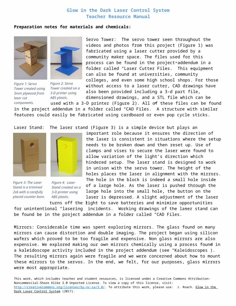
Servo Tower: The servo tower seen throughout the videos and photos from this project (Figure 1) was fabricated using a laser cutter provided by a community maker space. The files used for this process can be found in the project addendum in a folder called “Laser Cutter Files.” This equipment can also be found at universities, community colleges, and even some high school shops. For those without access to a laser cutter, CAD drawings have also been provided including a 3-d part file, dimensioned drawings, and a STL file which can be used with a 3-D printer (Figure 2). All of these files can be found in the project addendum in a folder called “CAD Files.” A structure with similar features could easily be fabricated using cardboard or even pop cycle sticks.
Laser Stand: The laser stand (Figure 3) is a simple device but plays an important role because it ensures the direction of the laser is consistent in situations where the setup needs to be broken down and then reset up. Use of clamps and vises to secure the laser were found to allow variation of the light’s direction which hindered setup. The laser stand is designed to work in unison with the servo tower. The height of the holes places the laser in alignment with the mirrors. The hole in the block is indeed a small hole inside of a large hole. As the laser is pushed through the large hole into the small hole, the button on the laser is depressed. A slight adjustment of the laser turns off the light to save batteries and minimize opportunities for unintentional “lasering” incidents. Working drawings of the laser stand can be found be in the project addendum in a folder called “CAD Files.”
Mirrors: Considerable time was spent exploring mirrors. The glass found on many mirrors can cause distortion and double imaging. The project began using
silicon wafers which proved to be too fragile and expensive. Non glass mirrors are also expensive. We explored making our own mirrors chemically using a process found in a kaleidoscope activity included in the project addendum (see “Kaleidoscopes”). The resulting mirrors again were fragile and we were concerned about how to mount these mirrors to the servos. In the end, we felt, for our purposes, glass mirrors were most appropriate.
Binder Clamps: The binder clamps were modified by drilling a 1/8” hole on the end. This allows the binder clamp to easily be mounted onto one of servo horns included with the servos. See Servo Motor Assembly below.
Servo Motor Assembly: Setup of the servo motor is important. In order for angular calculations to be successful, the procedure presented in the “Setting Up the Servo Mirror” video is critical (https://www.youtube.com/watch?v=ZaYL4qBdycc).
Laser: Even with proper emphasis on safety, the possibility of lasers being used in an immature fashion will always exist. I utilized multiple strategies to minimize accidental or intentional exposure to lasers:
1. Verbal emphasis on dangers presented by lasers.2. Lasers were not available until the second day of the activity.3. Lasers were wrapped in cellaphane filtering wrap.4. Laser holders were designed to easily disengage laser switch.5. Students and class visitors were provided with and required to wear laser safety glasses.
This work, which includes teacher and student resources, is licensed under a Creative Commons Attribution-Noncommercial-Share Alike 3.0 Unported License. To view a copy of this license, visit: http://creativecommons.org/licenses/by-nc-sa/3.0/. To attribute this work, please use: J. Roach. Glow in the Dark Laser Control System (2017).
Figure 1: Servo Tower created using 3mm plywood from laser cut components.
Figure 2: Servo Tower created on a 3-D printer using ABS plastic.
Figure 3: The Laser Stand is a trimmed 2x6 with a carefully placed counter-bore.
Figure 4: Laser Stand created on a 3-D printer using ABS plastic.
Glow in the Dark Laser Control SystemTeacher Resource Manual
Preparation notes for materials and chemicals (continued):
Projection Screen: The creation of the projection screens was achieved by cutting down foam board to 9”x12” pieces and adhering the glow in the dark paper to the foam board. An option is to print the provided file, “Register Marks.pdf,” onto the glow in the dark paper. This will permit students to later align their project grids with their coded projections and check for accuracy. See video, “Checking Your Programs for Accuracy,” for an explanation about this technique (https://www.youtube.com/watch?v=ZB5gWVHQSD0).
Jumper Cables: Colors matter to students with beginner bread board skills. Using the colors discussed in the video, “Wiring Setup” (https://www.youtube.com/watch?v=8kq8CwdkkDw), will also make it easier to troubleshoot problems.
Cellophane Filter Wrap: For our purposes, we cut the wrap into 3”x3” pieces.
Arduino Software: This free software is available at www.arduino.org/downloads and is easily installed. Safety:
The specified lasers are classified as class two lasers. If used carelessly they can cause retinal damage. Even with proper emphasis on safety, the possibility of lasers being used in an immature fashion will always exists. It is recommended to administer multiple strategies to minimize accidental or intentional exposure to lasers:
1. Verbal emphasis on dangers presented by lasers.2. Lasers were not available until the second day of the activity.3. Lasers were wrapped in cellaphane filtering wrap.4. Laser holders were designed to easily disengage laser switch.5. Students and class visitors were provided with laser safety glasses.
Waste disposal:
For the most part the materials can be used again and again. The only waste disposal other than broken or damaged equipment would be retiring expired AAA batteries. In my community, this can be accomplished by taken the dead batteries to Home Depot.
Materials/Supplies/Equipment needed with example source listed/pricing/CAS # and contact information:
This activity is a computer based module. The required Arduino software can be downloaded free of charge from www.arduino.org/downloads.
This activity also requires the use of a calculator with trigonometric functions. Both my students and I prefer handheld calculators although some students did use computer based calculators during the lab. Students should be advised to set calculators to degrees.
Additionally, this activity requires a hand held single-hole punch and a small Philips screwdriver.
The remaining required materials can be found on the next page:
This work, which includes teacher and student resources, is licensed under a Creative Commons Attribution-Noncommercial-Share Alike 3.0 Unported License. To view a copy of this license, visit: http://creativecommons.org/licenses/by-nc-sa/3.0/. To attribute this work, please use: J. Roach. Glow in the Dark Laser Control System (2017).

Glow in the Dark Laser Control SystemTeacher Resource Manual
Part Description Seller Part Number
Price Price/Unit Qty. Price
1 Spring Clamp Set 22 pieces (4x2",8x3",6x4",4x6")Note: Required 2 x 3” and 1 x 4” per group
Home Depot TGS0073F 8.97 0.41 3 1.23
2 Mini Round 2" Small Glass Mirror Circles/Package of 50 Amazon/P.U. Products 6.32 0.13 2 0.26
3 Rubber Band Office Depot 855883 7.79 0.08 1 0.08
4 Universal Small Binder Clips/Package of 144 Amazon/Plexsupply 7.60 0.05 2 0.11
5 Hitec Horizontal Servo Horn Attachment (included with Hitec servo) Amazon/Liquid RC n/a n/a 2 0.00
6 Hitec 31311s HS-311 Servo Standard Universal Amazon/Liquid RC 7.99 7.99 2 15.98
7 Allied Converters Cellophane, 20" x 150" Rolls (4) R Y B GNote: Required 3” x 3” red square per laser
Frey Scientific 341773 13.99 0.01 1 0.01
8 Laser Stand (use 2"x6"x8' Kiln Dried heat Treated Spruce Pine Fir)Note: Refer to project addendum for further description
Home Depot 5.72 0.18 1 0.18
9 Energizer Alkaline AAA Batteries/pack of 24 Home Depot 14.98 0.63 2 1.26
10 5mW 405nm Blue Violet Laser Pointer/Package of 10 Dhgate.com 60.11 6.01 1 6.01
11 HDE Laser Eye Protection Safety Glasses (red) Amazon 8.99 8.99 3 26.97
12 Arduino Uno R3 Microcontroller A000066 Amazon/Mp3Car Store A000066 16.06 16.06 1 16.06
13 Microtivity IB401 400-point Experiment Breadboard w/ Jumper Wires Amazon/Oxes 4.29 4.29 1 4.29
14 Servo Tower (used 12" x 24" 3 mil plywood)Note: Refer to project addendum for further description
Fab Lab Champaign, IL 7.00 3.50 1 3.50
15 Jumper Cables (included with Microtivity Breadboard) Amazon/Oxes n/a n/a 10 0.00
16 Hi-Speed USB 2.0 type A to B Printer Scanner Cable - 6 feet/pack of 3 Amazon 9.99 3.33 1 3.33
17 Pacon Foam Board 30" x 20" x 187 mil, black/ Carton of 10Note: Cut to 9” x 12” for each group
Office Depot 151297 27.89 0.70 1 0.70
18 Glow in the Dark Paper Pack (8.5x11 adhesive)/Package of 15 Steve Spangler Science WGLS-150 29.99 2.00 1 2.00
TOTAL COST PER GROUP OF 3 STUDENTS 81.97
Day 1: This work, which includes teacher and student resources, is licensed under a Creative Commons Attribution-Noncommercial-Share Alike 3.0 Unported License. To view a copy of this license, visit: http://creativecommons.org/licenses/by-nc-sa/3.0/. To attribute this work, please use: J. Roach. Glow in the Dark Laser Control System (2017).
Glow in the Dark Laser Control SystemTeacher Resource Manual
Note: No Lasers are used on the first day. It is recommended that the lasers are not distributed to the students until Day 2 to avoid mischief.
Required Equipment and Materials:
Computer with Arduino software and the following materials from the Material Checklist: Two Servo Assemblies
o Two Mini Round 2” Small Glass Mirror Circleso Two Universal Small Binder Clips (should have 1/8” drilled hole at base)o Two Hitec Horizontal Servo Horn Attachmentso Two Hitec 31311s HS-311 Servo Standard Universalo Small Philips screwdriver only if servo mirror assemblies are not complete
One Arduino Uno R3 Microcontroller A000066 One Microtivity IB401 400-point Experiment Breadboard Ten Jumper Cables (recommend: 3 red, 3 black, 2 white, 2 yellow) One Hi-Speed USB 2.0 type A to B Printer Scanner Cable
Objectives:
Students will:
build servo assemblies, if necessary, and inspect to meet specifications. connect project components. enter, compile, and upload a program into the Arduino setup. experiment with program variables in Arduino software and then compile and upload programs to Arduino to see
physical results.
Procedure:
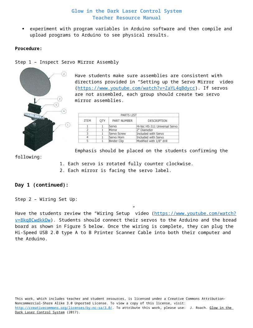
Step 1 – Inspect Servo Mirror Assembly
Have students make sure assemblies are consistent with directions provided in “Setting up the Servo Mirror” video (https://www.youtube.com/watch?v=ZaYL4qBdycc). If servos are not assembled, each group should create two servo mirror assemblies.
Emphasis should be placed on the students confirming the following:1. Each servo is rotated fully counter clockwise.2. Each mirror is facing the servo label.
This work, which includes teacher and student resources, is licensed under a Creative Commons Attribution-Noncommercial-Share Alike 3.0 Unported License. To view a copy of this license, visit: http://creativecommons.org/licenses/by-nc-sa/3.0/. To attribute this work, please use: J. Roach. Glow in the Dark Laser Control System (2017).

Glow in the Dark Laser Control SystemTeacher Resource Manual
Day 1 (continued):
Step 2 – Wiring Set Up:
Have the students review the “Wiring Setup” video (https://www.youtube.com/watch?v=8kq8CwdkkDw). Students should connect their servos to the Arduino and the bread board as shown in Figure 5 below. Once the wiring is complete, they can plug the Hi-Speed USB 2.0 type A to B Printer Scanner Cable into both their computer and the Arduino.
Figure 5: The emphasis on the white wire going to number 12 and the yellow wire connecting to number 13 will be used to help students distinguish between the top and the bottom servos which serve different functions for moving the light. The bottom (#12) servo controls horizontal movement and the top (#13) controls vertical movement.
Note: If programs were previously uploaded to the students Arduinos, they may notice some activity upon connecting their device setup. This can be stopped by opening a new Arduino file, saving it without making changes, and uploading it to the Arduino.
This work, which includes teacher and student resources, is licensed under a Creative Commons Attribution-Noncommercial-Share Alike 3.0 Unported License. To view a copy of this license, visit: http://creativecommons.org/licenses/by-nc-sa/3.0/. To attribute this work, please use: J. Roach. Glow in the Dark Laser Control System (2017).

Glow in the Dark Laser Control SystemTeacher Resource Manual
Day 1 (continued):
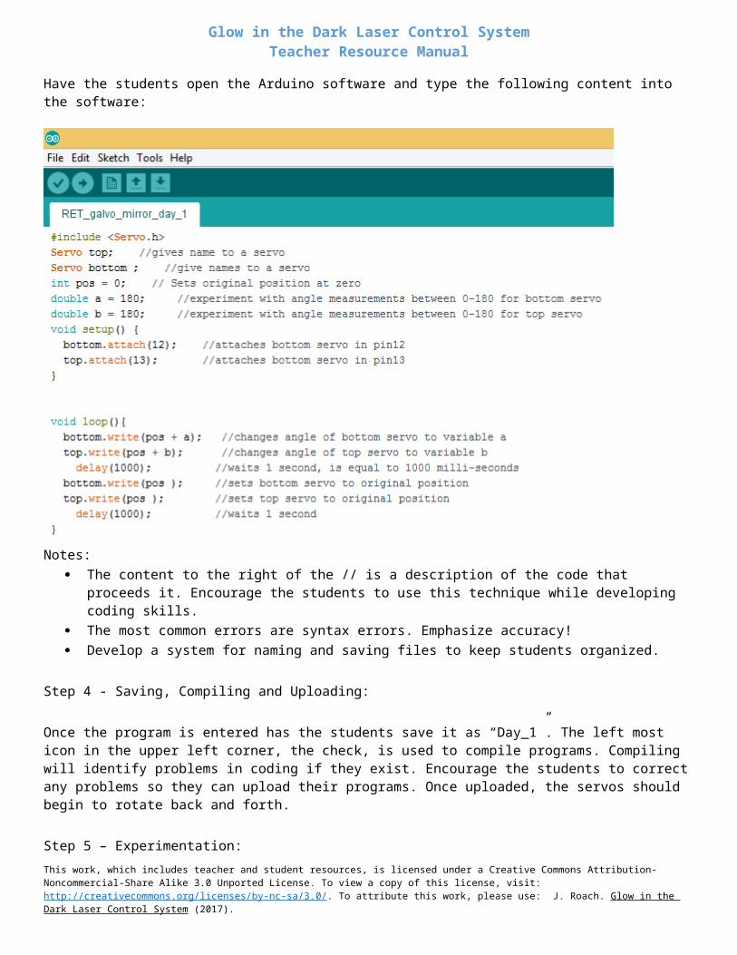
Step 3 – Coding:Have the students open the Arduino software and type the following content into the software:
Notes: The content to the right of the // is a description of the code that proceeds it. Encourage the students to use this
technique while developing coding skills. The most common errors are syntax errors. Emphasize accuracy! Develop a system for naming and saving files to keep students organized.
Step 4 - Saving, Compiling and Uploading:
Once the program is entered has the students save it as “Day_1”. The left most icon in the upper left corner, the check, is used to compile programs. Compiling will identify problems in coding if they exist. Encourage the students to correct any problems so they can upload their programs. Once uploaded, the servos should begin to rotate back and forth.
Step 5 – Experimentation:
Have the students experiment with changing the angles and the delay. They should save, compile, and upload each experiment and observe the results. Understanding angles is paramount in this activity. Each student in every group should be typing their own files and taking turns uploading them to the Arduino.
This work, which includes teacher and student resources, is licensed under a Creative Commons Attribution-Noncommercial-Share Alike 3.0 Unported License. To view a copy of this license, visit: http://creativecommons.org/licenses/by-nc-sa/3.0/. To attribute this work, please use: J. Roach. Glow in the Dark Laser Control System (2017).
Glow in the Dark Laser Control SystemTeacher Resource Manual
Day 2:
Required Equipment and Materials:
Computer with Arduino software, servo mirror setup with bread boards and Arduino from Day 1 and the remaining materials from the Material Checklist:
Spring Clamp – two 3” and one 4” One Rubber Band 3” x 3” Red Cellophane Film Laser Stand Two AAA Batteries 5mW 405nm Blue Violet Laser Pointer Servo Tower Projection Screen with Glow in the Dark Paper with Register Marks HDE Laser Eye Protection Safety Glasses Hand Held Calculator with Trigonometric Functions Hole Punch Copies of Handouts
o “Register Marks” (if not printed on glow in the dark paper)o “Project Grid” (punch holes on 4 register marks)o “Day 2 Triangle” (punch holes on 4 register marks)o “Day 2 Triangle Calculations” (answer key is included)o “Day 2 Triangle Coding” (triangle coding solution is included)o “Day 2 Square” (punch holes on 4 register marks)o “Day 2 Square Calculations” (answer key is included)o “Day 2 Square Coding” (square coding is included)
Note: All the worksheets with registered marks were created using AutoCAD R17. For the highest level of accuracy, it is recommended that these files are used and sent directly to a printer. If this is not an option, the PDF’s aren’t as accurate as the DWG files but are acceptable for use for this activity. Check register mark alignment between the different documents being provided to the students to ensure accuracy. Photo copiers tend to have notable variances between copies; 2nd, 3rd, (etc.) generation copies will exaggerate these variances.
Safety:
Today students will be using lasers. The following is recommended as a three-prong safety plan:
Students should be reminded even using the filtering cellophane film and the laser protection glasses, lasers should only be pointed into servo mirrors.
Distribute laser protection glasses. Students should wear them immediately. Distribute lasers, batteries, red cellophane, rubber bands and laser stands and immediately have students affix
cellophane to the light end of the laser with a rubber band. (This process is modeled in the “Laser Alignment” video (https://www.youtube.com/watch?v=OfBtjbNOC-Y).
Day 2 (continued):This work, which includes teacher and student resources, is licensed under a Creative Commons Attribution-Noncommercial-Share Alike 3.0 Unported License. To view a copy of this license, visit: http://creativecommons.org/licenses/by-nc-sa/3.0/. To attribute this work, please use: J. Roach. Glow in the Dark Laser Control System (2017).

Glow in the Dark Laser Control SystemTeacher Resource Manual
Objectives:
Students will:
follow procedures to ensure safe use of lasers. configure servo tower and laser stand to control reflection of laser beam. determine angular values of servos using formulas for controlled movement of laser beam. create programs to address specific challenges presented. evaluate accuracy of programming using register mark system.
Procedure:
Step 1 – Initiate Safety:
All students should immediately put on laser safety glasses. Install batteries into laser and mount laser on laser stand. Push the laser through the larger hole, beam first. Laser should light as the button is depressed when the button makes contact with the smaller hole. Pull back slightly to turn off laser and wrap cellophane wrap around light end with rubber band.
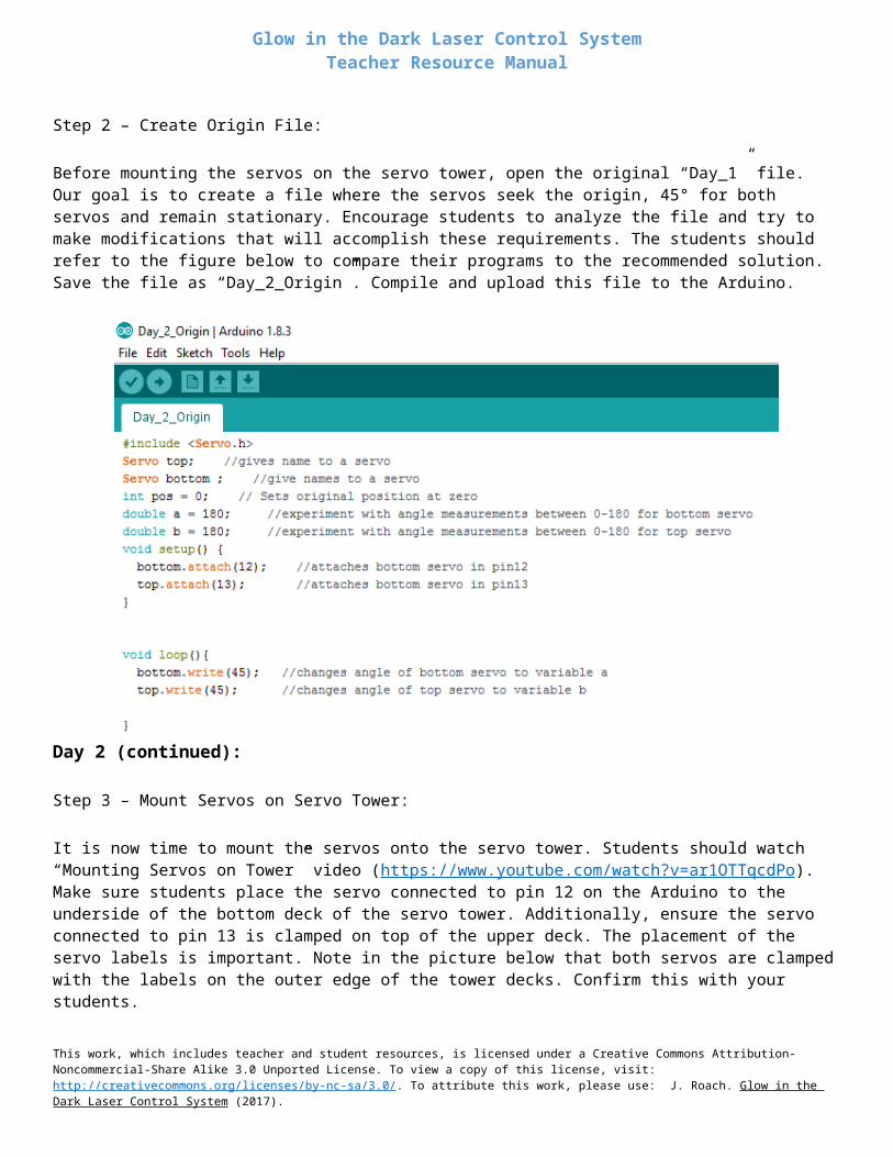
Step 2 – Create Origin File:
Before mounting the servos on the servo tower, open the original “Day_1” file. Our goal is to create a file where the servos seek the origin, 45° for both servos and remain stationary. Encourage students to analyze the file and try to make modifications that will accomplish these requirements. The students should refer to the figure below to compare their programs to the recommended solution. Save the file as “Day_2_Origin”. Compile and upload this file to the Arduino.
Day 2 (continued):
This work, which includes teacher and student resources, is licensed under a Creative Commons Attribution-Noncommercial-Share Alike 3.0 Unported License. To view a copy of this license, visit: http://creativecommons.org/licenses/by-nc-sa/3.0/. To attribute this work, please use: J. Roach. Glow in the Dark Laser Control System (2017).
Glow in the Dark Laser Control SystemTeacher Resource Manual
Step 3 – Mount Servos on Servo Tower:
It is now time to mount the servos onto the servo tower. Students should watch “Mounting Servos on Tower” video (https://www.youtube.com/watch?v=ar1OTTqcdPo). Make sure students place the servo connected to pin 12 on the Arduino to the underside of the bottom deck of the servo tower. Additionally, ensure the servo connected to pin 13 is clamped on top of the upper deck. The placement of the servo labels is important. Note in the picture below that both servos are clamped with the labels on the outer edge of the tower decks. Confirm this with your students.
Step 4 – Laser Alignment:
Next, students should align the laser with the servo tower setup. Please watch the video, “Laser Alignment” (https://www.youtube.com/watch?v=OfBtjbNOC-Y). Double check student measurements from the screen to the center axis of the top servo to ensure a measurement of 10 inches. When finished, the students’ lasers should be shining on the center of the project screen. Note in the video, books were used to elevate the system to the right height.Step 5 – Align Laser with Origin on Grid:Students should view the video, “Checking Programs for Accuracy” (https://www.youtube.com/watch?v=ZB5gWVHQSD0). Help the students use the template document, “Project Grid,” and align the register marks as shown in the video. Adjust the screen so the program, “Day_2_Origin,” is shining the laser beam at the intersection of the X and Y axes. Further adjustment will likely be necessary later, but this is a perfect starting point. Turn off the laser.
Day 2 (continued):
Step 6 – Introducing the Formulas:This work, which includes teacher and student resources, is licensed under a Creative Commons Attribution-Noncommercial-Share Alike 3.0 Unported License. To view a copy of this license, visit: http://creativecommons.org/licenses/by-nc-sa/3.0/. To attribute this work, please use: J. Roach. Glow in the Dark Laser Control System (2017).
Glow in the Dark Laser Control SystemTeacher Resource Manual
Locate the sheet, “Day 2 Triangle Calculations.” Note the triangle shown is defined by 3 points using Cartesian Coordinates, each point having an X and Y values. The formulas have been provided below.
Emphasize calculators should be set to degrees before continuing with calculations. Perform each of the six calculations.
Step 7 – Coding:
The results from the provided calculations have been inserted into the coding sequence in “Day 2 Triangle Coding.” The students should use this document to enter the Triangle program into the Arduino software. Save as “Day_2_Triangle.” Compile and check for errors. Make changes, if necessary, resave, and upload the program to the Arduino.
Day 2 (continued):
Step 8 – Check for Accuracy:This work, which includes teacher and student resources, is licensed under a Creative Commons Attribution-Noncommercial-Share Alike 3.0 Unported License. To view a copy of this license, visit: http://creativecommons.org/licenses/by-nc-sa/3.0/. To attribute this work, please use: J. Roach. Glow in the Dark Laser Control System (2017).

Glow in the Dark Laser Control SystemTeacher Resource Manual
Align the sheet, “Day 2 Triangle”, with the register marks on the projection screen. Turn on the laser and evaluate the triangle tracing the template on the screen. It may be necessary to make slight angular adjustments with the screen. Are the points of the laser triangle matching the points on the template? It may be necessary to double check your program for accuracy. Step 9 – Repeat Steps 6, 7 & 8 for a new shape:
Use “Day 2 Square Calculations” worksheet and perform calculations for X and Y for Points A, B, C, and D. Enter the Code into the Arduino software. Save the file as “Day_2_Square”. Compile your program, fix errors (if necessary), and resave if necessary. Upload the program. Evaluate your square using the “Day 2 Square” template. Make corrections to your coding as necessary.
Days 3 & 4:
Required Equipment and Materials:
This work, which includes teacher and student resources, is licensed under a Creative Commons Attribution-Noncommercial-Share Alike 3.0 Unported License. To view a copy of this license, visit: http://creativecommons.org/licenses/by-nc-sa/3.0/. To attribute this work, please use: J. Roach. Glow in the Dark Laser Control System (2017).
Glow in the Dark Laser Control SystemTeacher Resource Manual
Computer with Arduino software, all from the Material Checklist:
Hand Held Calculator with Trigonometric Functions Hole Punch Copies of Handouts
o “Register Marks” (if not printed on glow in the dark paper)o “Project Grid” (punch holes on 4 register marks)o “Final Assessment Calculation Sheet 1 of 2” & “Final Assessment Calculation Sheet 2 of 2”
Assignment:
Each student is required to create a shape defined by a minimum of ten points. To complete this assignment each student must submit the following:
The shape defined on Project Grid sheet using a minimum of 10 points defined with Cartesian Coordinates. Calculations defining top and bottom servo positions for each of your defined points. These calculations must be
submitted on the Final Assessment Calculation Sheet Arduino Program
Additionally each student must provide an on screen demonstration that their points are in alignment using the register mark system taught in this module.
Presentation talking points:
Slide 1: The route from “science project” to modular student activity: see student interview video, (https://www.youtube.com/watch?v=zmsa33seh8c)
Used to plan a course of action based on successes and failures Determined design criteria for
o Servo Mirror Assemblyo Servo Towero Laser Stando Formation of Formulas
Trained Lab Aides to ensure smoothest possible rideSlide 2: Student Reaction to activity (https://www.youtube.com/watch?v=N6zhF3jJGko)
This activity was performed 6th period the last week of school Participation was enthusiastic with a high level of student involvement
Slide 3: This activity can be performed on other platforms. (https://www.youtube.com/watch?v=v3DOe9FXCxQ)
We were successful in having a student execute this activity using VEX components with RobotC software.
Slide 4: Enrichment Activities Provide a program that executes curves such as a sine wave. Experiment with engraving or etching Experiment with lenses
Links to the research articles and other resources:
Altan, T.; DIY Laser Show Number 6; 2007; https://www.youtube.com/watch?v=qCUiCs-aYNkThis work, which includes teacher and student resources, is licensed under a Creative Commons Attribution-Noncommercial-Share Alike 3.0 Unported License. To view a copy of this license, visit: http://creativecommons.org/licenses/by-nc-sa/3.0/. To attribute this work, please use: J. Roach. Glow in the Dark Laser Control System (2017).

Glow in the Dark Laser Control SystemTeacher Resource Manual
Arduino; www.arduino.org/downloads
Association of Iron & Steel Technologies; https://www.aist.org/home.aspx
Champaign Urbana Community Fab Lab, Urbana, IL; http://cucfablab.org/
II-VI Infrared; http://www.iiviinfrared.com/CO2-Laser-Optics/scanning-laser-system-optics.html
Ives, Rob; Notes.Robives.com; Servos (Nov. 7, 2015); https://notes.robives.com/servos/
Next Generation Science Standards; https://www.nextgenscience.org/
Research Laboratory of Electronics; Laser Medicine & Medical Imaging; http://www.rle.mit.edu/media/pr143/11.pdf
AcknowledgmentsThe author acknowledges the contribution of Dr. Arend Van Der Zande, Joe Muskin, Sunphil Kim, Dr. Pinshane Huang, Yunjo Jeong, Nikita Buzov, Fatou Cisse, Blanka Janicek, and the help of the MNTL staff, especially Mr. Edmond K. C. Chow and Ms. Meredith C. Gleety. Special thanks to project managers Dr. Irfan Ahmad and Carrie Kouadio and Center for Nanoscale Science and Technology support. We also appreciate our usage of the Beckman Institute’s equipment. This research has been made possible by the NSF with the additional help of the nano@Illinois staff. Additionally, thanks are extended to those from J. Sterling Morton High School District 201 who supported this endeavor: Jose Gamboa, Erik Mastey, Anne Semenske, Veronica Herrera, and the students who participated in this project, specifically, Luis Vazquez, Hernan Avitia, and my 6th period Principles of Engineering class. Finally, thanks to my daughter, Janellie Roach, for supporting me as I dipped my toes into the use of social media.
This work, which includes teacher and student resources, is licensed under a Creative Commons Attribution-Noncommercial-Share Alike 3.0 Unported License. To view a copy of this license, visit: http://creativecommons.org/licenses/by-nc-sa/3.0/. To attribute this work, please use: J. Roach. Glow in the Dark Laser Control System (2017).

Glow in the Dark Laser Control SystemTeacher Resource Manual
This work, which includes teacher and student resources, is licensed under a Creative Commons Attribution-Noncommercial-Share Alike 3.0 Unported License. To view a copy of this license, visit: http://creativecommons.org/licenses/by-nc-sa/3.0/. To attribute this work, please use: J. Roach. Glow in the Dark Laser Control System (2017).
Financial support was provided by the National Science Foundation under grant #NSF EEC 14-07194 RET, as part of the nano@illinois Research Experiences for Teachers (RET) project, managed and coordinated through the Center for Nanoscale Science and Technology collaboratory and the Micro and Nanotechnology Lab at the University of Illinois at Urbana-Champaign.
This work, which includes teacher and student resources, is licensed under a Creative Commons Attribution-Noncommercial-Share Alike 3.0 Unported License. To view a copy of this license, visit: http://creativecommons.org/licenses/by-nc-sa/3.0/. To attribute this work, please use [“J. Doe. Title (Date).”]
The nano@illinois Research Experience for Teachers (RET) at the University of Illinois at Urbana-Champaign (from 2014-2017) exposes a diverse set of in-service and pre-service science, technology, engineering, and mathematics (STEM) teachers and community college faculty from across the nation to cutting-edge research in nanotechnology. The RET focuses on recruiting underrepresented minority populations (focused on ethnicity, geography, disability, and veteran status) including women and will target teachers from high-need areas, including inner city, rural, low-income, and those with significant URM students. Participants conduct research over 6 weeks in world-class labs with 4 follow-up sessions during the school year.
Teacher professional development opportunities includes teacher-focused lectures, mentoring, networking, poster sessions, ethics seminars, hands-on modules, STEM education issues, career choices, and resources for implementing a nano lab and curriculum. Teachers will develop modules to be disseminated widely and present their results. High-quality follow-up sessions and evaluation will be infused.
Center for Nanoscale Science and Technology208 N. Wright, MC-249Urbana, Illinois 61801217-244-1353nanotechnology@illinois.eduwww.nano.illinois.edu