nano 5 card user manual -...
TRANSCRIPT

Nano 5 Card User Manual
Figure 1.- Nano 5 + Raspberry Pi
I.- Nano 5 Features
a.- 6 Analog Inputs ( ADCs, 12 bits, 2.5V)
b.- 2 Analog Outputs ( DACs, 12 bits, 2.5V)
c.- 1 Switch (connected to P2.4)
d.- 1 Test Led (connected to P2.5)
e.- 2 PWM Channels ( or GPDIO)
f.- 2 Interrupt Inputs
g.- 1 Real Time Clock (PCF2127T, with CR1220 Battery)
h.- 9 GPDIO (12 if Rotary Encoder is not used)
i.- 2 Relays
j.- 2 Timers/Counters
k.- Communication Protocols: UART, I2C, SPI (8 bits)
l.- Nano 5 Power: USB or Raspberry Pi
m.- Microconverter: ADuC842, 16 MHz
n.- Memory:
1.- Program: 64K x 8
2.- Flash: 4K x 8
3.- User RAM: 256 bytes
4.- User XRAM: 2K x 8
Other features:
1 Led shows Power On
2 Leds shows the status of UART Communication
2 Leds shows the Relays status

II.- Block Diagram
The general sections of Nano 5 card are (see Fig. 2):
1.- Microconverter: ADuC842 at 16MHz. User manual.
2.- USB to UART Converter: Establishes communication between the USB of PC and UART
interface of microconverter. This is used for program the ADuC842 and communication between
Nano 5 and PC using a terminal emulator (for example, Teraterm).
3.- Nano 5/Raspberry Pi Conversion Module: Converts 5V to 3.3V for UART and I2C
communication. The Rasberry PI can supply +5V to the Nano 5 if configured. (see Power Source
in Section III).
4.- Real Time Clock: The RTC module is implemented using the PCF2127T. The interface,
based on I2C communication, use the address A2H.
5.- Relays and Rotary Encoder: The two relays can control maximun loads of 250V (10A). The
rotary encoder has 24 steps.
6.- USB Connector: The Nano 5 can be powered and programmed through the USB connector.
The USB interface also supports hyper terminal communication with PC.
7.- Led and Switch for test: Can be used for test the card and implement basic programs.
Figure 2.- Block diagram of Nano 5
The status of several functions are shown using leds: Relays (on/off), UART communication,
Power On and a led to general test. This is shown in Fig. 3 and 4.
The GPDIO used for controlling the Relays is described in Fig. 4, it shows the Nano 5 with the
LCD.
Microconverter
USB to UART Converter
Real Time Clock
Relays and Rotary Encoder
Nano 5/Raspberry Pi Conversion Module
USB: Programming/Power
Led and Switch
for Test

Figure 3.- Leds show the status of the Nano 5 card.
Figure 4.- Front view of Nano 5 card with LCD.
The RCA Universal Remote Controller RCRN03BR may be used as an Infrared Interface for the
Nano 5 Card. The code that must be programmed is: 10810 (Sony).
P3.7=0
P3.6=0
P3.6=1 RESET (LED ON)
IR SENSOR
SW
ROTARY ENCODER
SW
LCD (20x4, I2C)
SW
RELAY 2
SW
RELAY 1
SW
P3.7=1 RESET (LED ON)
Relay 1 Status
SW
USB: PROGRAMMING/POWER
SW
RESET
SW
PROG
SW
Relay 2 Status
SW Power On
SW
Tx (UART)
Rx (UART)
Led (General Purpose)
Switch (General Purpose)
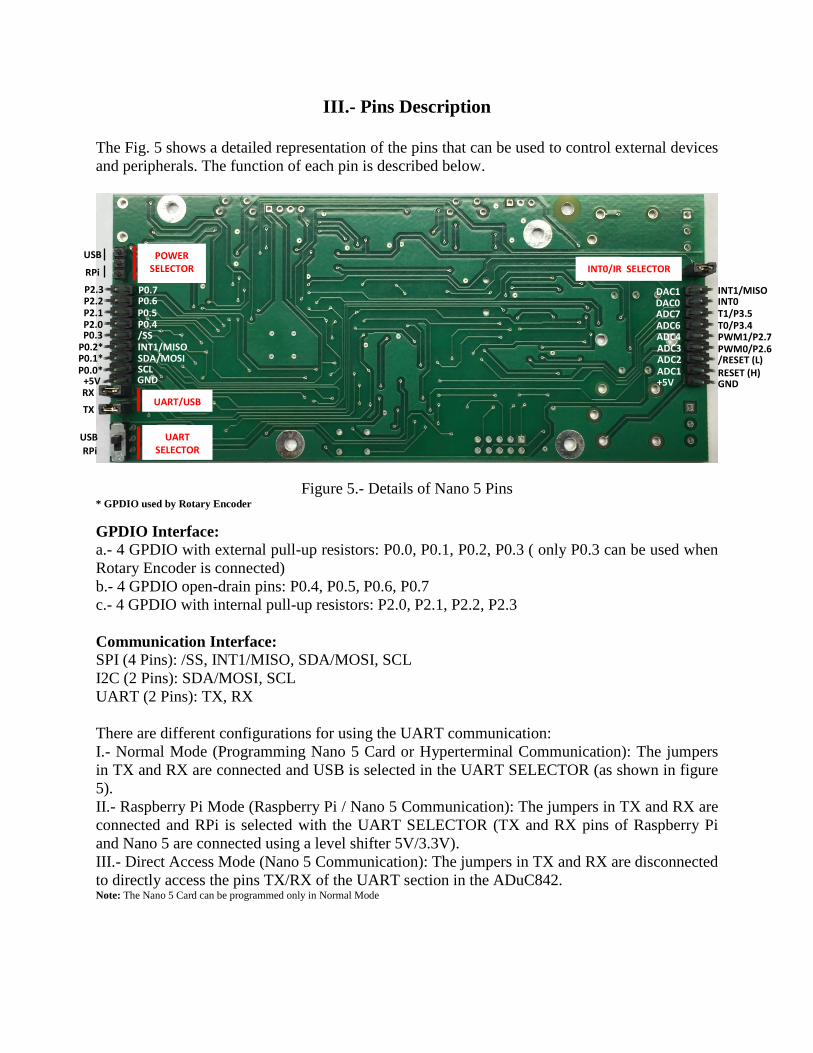
III.- Pins Description
The Fig. 5 shows a detailed representation of the pins that can be used to control external devices
and peripherals. The function of each pin is described below.
Figure 5.- Details of Nano 5 Pins * GPDIO used by Rotary Encoder
GPDIO Interface:
a.- 4 GPDIO with external pull-up resistors: P0.0, P0.1, P0.2, P0.3 ( only P0.3 can be used when
Rotary Encoder is connected)
b.- 4 GPDIO open-drain pins: P0.4, P0.5, P0.6, P0.7
c.- 4 GPDIO with internal pull-up resistors: P2.0, P2.1, P2.2, P2.3
Communication Interface:
SPI (4 Pins): /SS, INT1/MISO, SDA/MOSI, SCL
I2C (2 Pins): SDA/MOSI, SCL
UART (2 Pins): TX, RX
There are different configurations for using the UART communication:
I.- Normal Mode (Programming Nano 5 Card or Hyperterminal Communication): The jumpers
in TX and RX are connected and USB is selected in the UART SELECTOR (as shown in figure
5).
II.- Raspberry Pi Mode (Raspberry Pi / Nano 5 Communication): The jumpers in TX and RX are
connected and RPi is selected with the UART SELECTOR (TX and RX pins of Raspberry Pi
and Nano 5 are connected using a level shifter 5V/3.3V).
III.- Direct Access Mode (Nano 5 Communication): The jumpers in TX and RX are disconnected
to directly access the pins TX/RX of the UART section in the ADuC842. Note: The Nano 5 Card can be programmed only in Normal Mode
POWER SELECTOR SW
USB
RPi
UART/USB
SW
RX
TX
UART SELECTOR
SW
RPi
USB
P2.3 P2.2 P2.1 P2.0 P0.3
P0.2* P0.1* P0.0*
+5V
P0.7 P0.6 P0.5 P0.4 /SS INT1/MISO SDA/MOSI SCL GND
INT0/IR SELECTOR
INT1/MISO
T1/P3.5
6 T0/P3.4 PWM1/P2.7 PWM0/P2.6
INT0
/RESET (L) RESET (H) GND
DAC1 DAC0 ADC7 ADC6 ADC4 ADC3 ADC2 ADC1 +5V

Power Source (5V):
a.- USB Power: The jumper in POWER SELECTOR (see Fig. 5) must be connected to USB (as
shown in Fig. 4). The power source for Nano 5 Card is taken from USB/Programming Cable.
b.- Raspberry Pi Powered: The jumper in POWER SELECTOR (see Fig. 5) must be connected
to RPi. The power source for Nano 5 Card is supplied by the Power Supply of the Raspberry Pi. Note: The power pins (+5V) in Nano 5 Card can be used to supply power to external devices
Analog Interface:
a.- 2 DACs ( 12 bits, 2.5V): DAC0, DAC1
8.- 6 ADCs ( 12 bits, 2.5V): ADC1, ADC2, ADC3, ADC4, ADC6, ADC7
External Interrupts:
a.- INT0: Is used by the IR Remote Controller (the jumper in INT0/IR SELECTOR must be
connected, as shown in Fig. 5). When the IR Remote Controller is not used, the jumper can be
removed and INT0 can be used as general purpose interrupt.
b.- INT1/MISO: Can be used as a general purpose interrupt when SPI communication is not
used.
Timers/Counters Inputs:
a.- T0: Timer/Counter 0 Input
b.- T1: Timer/Counter 1 Input Note: When the Timers/Counters are not used, these pins can be used as GPDIO pins P3.4 (T0), P3.5(T1) with internal pull-up resistors
PWM Outputs:
a.- PWM0 (P2.6 Port): PWM0 Output
b.- PWM1 (P2.7 Port): PWM1 Output
Note: When the PWMs are not used, these pins can be used as GPDIO pins P2.6 (PWM0), P2.7(PWM1) with internal pull-up resistors
Reset Outputs (can drive external devices):
a.- RESET: High Level
b.- /RESET: Low Level
Note: These signals are generated by RESET switch

IV.- How to program the Nano 5 Card
The support webpage shows several examples of how to program the Nano 5 Card.
A short description is presented below.
1.- Write the program
2.- Compile the program
3.- Verify the result
4.- Install the driver of USB interface from Microchip (only the first time)
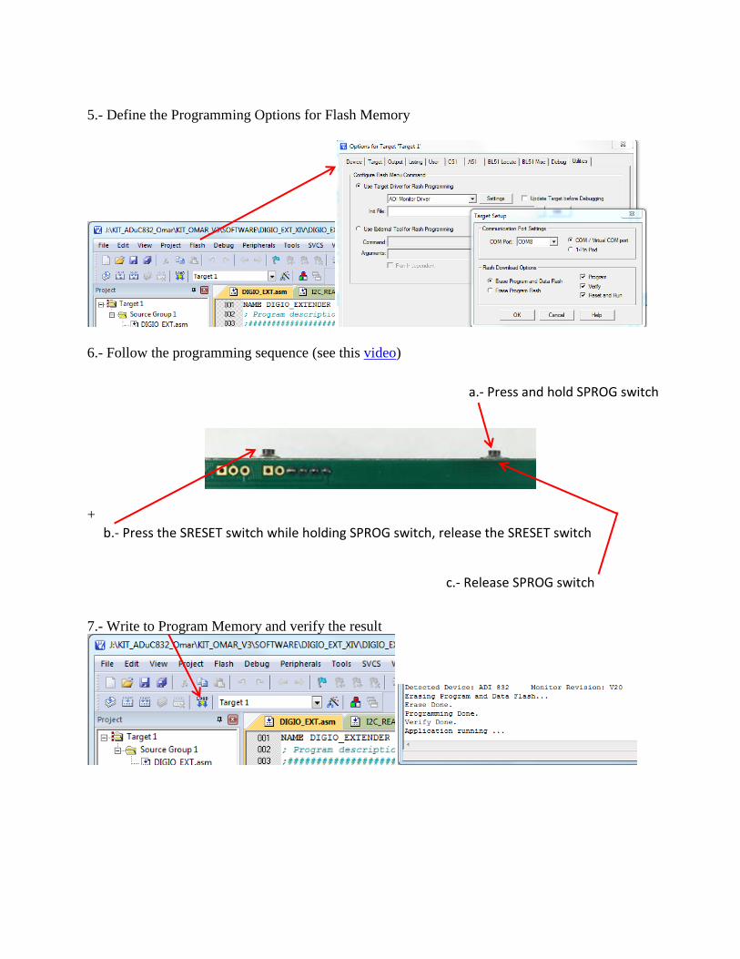
5.- Define the Programming Options for Flash Memory
6.- Follow the programming sequence (see this video)
+
7.- Write to Program Memory and verify the result
a.- Press and hold SPROG switch
b.- Press the SRESET switch while holding SPROG switch, release the SRESET switch
c.- Release SPROG switch
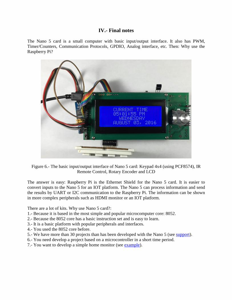
IV.- Final notes
The Nano 5 card is a small computer with basic input/output interface. It also has PWM,
Timer/Counters, Communication Protocols, GPDIO, Analog interface, etc. Then: Why use the
Raspberry Pi?
Figure 6.- The basic input/output interface of Nano 5 card: Keypad 4x4 (using PCF8574), IR
Remote Control, Rotary Encoder and LCD
The answer is easy: Raspberry Pi is the Ethernet Shield for the Nano 5 card. It is easier to
convert inputs to the Nano 5 for an IOT platform. The Nano 5 can process information and send
the results by UART or I2C communication to the Raspberry Pi. The information can be shown
in more complex peripherals such as HDMI monitor or an IOT platform.
There are a lot of kits. Why use Nano 5 card?:
1.- Because it is based in the most simple and popular microcomputer core: 8052.
2.- Because the 8052 core has a basic instruction set and is easy to learn.
3.- It is a basic platform with popular peripherals and interfaces.
4.- You used the 8052 core before.
5.- We have more than 30 projects than has been developed with the Nano 5 (see support).
6.- You need develop a project based on a microcontroller in a short time period.
7.- You want to develop a simple home monitor (see example).

V.- Available Versions
All versions have the same features (see Section I), the difference is the input peripherals and
extensions, as shown in figure 7. The test algorithms are applied depending on the version (for
example, the communication with Raspberry Pi is not tested in Nano 5a and Nano 5b, the Rotary
Encoder is not tested in Nano 5a).
Figure 7.- Nano 5 card Versions
In order to test the Nano 5 Card, use this programs.
Nano 5a Inputs: 1.- IR Remote controller 2.- Keypad 4x4 (using PCF8574)
Nano 5b Inputs: 1.- IR Remote controller 2.- Keypad 4x4 (using PCF8574) 3.- Rotary Encoder
Nano 5c Inputs: 1.- IR Remote controller 2.- Keypad 4x4 (using PCF8574) 3.- Rotary Encoder Extensions: 1.- Raspberry Pi 3