namur 43
TRANSCRIPT

Product Specifications
PSS 2A-1F5 AI/A Series® Temperature TransmittersModel RTT15 withHART, FOUNDATION Fieldbus, or Profibus Protocol
HOUSING
CODE E
CODE D
CODE F
CODES W AND Y
WITH DIN RAIL CLIP
BASIC MODULE
CODE C
HOUSING
HOUSING
HOUSING
HOUSING
HOUSING CODE B
CODES L AND MHOUSING
CODES S AND T WITH OPTIONAL LED INDICATOR (-L1)
The RTT15 is a microprocessor based temperature transmitter with HART, FOUNDATION Fieldbus H1, or Profibus PA Communication Protocol. It receives input signals from thermocouples, RTDs, ohm, or millivolt sources. It is available as a basic module, or in numerous housing configurations.
FEATURES• Superior accuracy and long term stability from
microprocessor-based technology.
• One unit configurable for TC, RTD, mV, and ohm.
• Supports 2-, 3-, or 4-wire RTDs.
• HART version allows average or difference measurement; Fieldbus/Profibus version allows average, difference, or redundant measurement.
• TC cold junction compensation.
• Galvanic isolation for both input and output.
• Automatic self-diagnostics and self-calibration.
• LED Indicator Options offered with HART.
• Basic module can mount to surface or DIN rail.
• Wide selection of bare sensors and thermowells.
• Numerous weatherproof and explosionproof housings for remote mounting, and integral sensor and well mounting.
• FOUNDATION Fieldbus with an LAS (Link Access Scheduler), PID (Proportional, Integral, Derivative) function block, and FISCO/FNICO Protection.
• Configurable failsafe mA value (HART).
• FMEDA report in support of SIL applications available for HART versions.
• Maximum/minimum temperature logging.
• Conforms to applicable European Union Directives (product marked with “CE” logo).
• EMC immunity per EU Directive 89/336/EEC.
• Compliant with NAMUR NE 21 criterion for burst.
• Meets many testing agency requirements for hazardous area installations.
• Standard 5-year warranty.

PSS 2A-1F5 APage 2
GENERAL DESCRIPTION
The RTT15 provides a wide range of packaging, sensor types, and options along with a choice of HART, FOUNDATION Fieldbus H1, or Profibus PA communication protocols, thus making this transmitter suitable for most temperature measurement applications. The microprocessor-based electronics minimizes ambient temperature effects and results in high accuracy, repeatability, and linearization of the sensor signal. Ease of mounting and installation makes these transmitters an extremely attractive offering.
I/A Series INTELLIGENT TEMPERATURE TRANSMITTER FAMILY
The RTT15 is part of the Foxboro intelligent temperature transmitter family, which also includes Models RTT20 and RTT25. Table 1 below lists a few parameters relating to each transmitter model, and the applicable PSSs which give specifications and a more complete description.
(a) Platinum and nickel RTDs for all Models; copper RTD for RTT20 and RTT25 only.
(b) LED indicator available with HART version only. Intrinsically Safe and Explosionproof versions offered.
EFFICIENT AND DURABLE
Industrial-grade integrated circuits and sealed electronics combine to make this microprocessor-based transmitter an efficient and durable device.
MULTIPLE PACKAGING CONFIGURATIONSThe transmitter is suitable for use in a variety of applications. A transmitter with an integrally mounted sensor (and well, if desired) is mounted directly to the process. Surface- and pipe-mounted configurations allow the transmitter to be mounted remotely from the process. The DIN B size basic transmitter module is intrinsically safe and is offered for replacement or spare parts purposes, for mounting to a surface, or for mounting to a DIN rail using a simple clip. A selection of weatherproof and explosionproof terminal heads is offered to satisfy hazardous area installations. Built-in protection from vibration and RFI is also provided. See Figure 1 for transmitter configurations.
INPUT TYPESThis RTT15 Transmitter can be used with a wide variety of temperature sensors, including 2-, 3-, and 4-wire RTDs, most popular thermocouples, and other resistance and millivolt input devices. The following is a general list of transmitter input types:
• Platinum RTDs, 2-, 3-, and 4-wire• Nickel RTD, 3-wire• Thermocouples• Millivolt• Ohm• Average, difference, or redundant measurement
with two 2-wire RTDs, two TCs, or two mV inputs (redundant measurement with Fieldbus/Profibus version only).
REMOTE COMMUNICATIONSRemote digital communication is provided with either HART, FOUNDATION Fieldbus H1, or Profibus PA communication protocols. One module is used for Fieldbus/Profibus communications. It has a unique feature of recognizing both Fieldbus and Profibus communications, and automatically switching to the applied protocol. The HART electronics is in a separate basic module. See the paragraphs that follow.
Foundation Fieldbus H1 Protocol(Version -F Electronics)This is an all digital, serial, two-way communication system which interconnects field devices, such as transmitters, actuators, and controllers. It is a Local Area Network (LAN) with built-in capability to distribute control application across the network. Fieldbus technology consists of a Physical Layer, a Communication Stack, and User Application Blocks.
An LAS can be assigned to a device for Scheduled Communication. A PID function block contains all the standard parameters required to implement a general purpose, automatic PID control scheme.
Table 1. Temperature Transmitter Family Comparison
PSS No. or Parameter
Temperature Transmitter
RTT15 RTT20 RTT25
PSS Number 2A-1F5 A 2A-1F4 A 2A-1F4 CHART: 4 to 20 mA and Digital
YES YES NO
FoxCom: 4 to 20 mA and Digital
NO YES NO
4 to 20 mA Analog - No Digital
NO YES NO
FOUNDATION Fieldbus, Digital
YES NO YES
Profibus, Digital YES NO NOThermocouple Input YES YES YESRTD Input (a) YES YES YESMilliamp Input NO NO YESMillivolt Input YES YES YESOhm Input YES YES YESDew Point Input NO YES NOCustom Input NO YES YESDual Inputs YES YES YESIndicator YES (b) YES YES

PSS 2A-1F5 APage 3
Figure 1. Multiple Packaging Configurations with Housing Codes Indicated
REMOTE COMMUNICATIONS (Cont.)
Profibus PA Protocol(Version -P Electronics)
This is an all digital, serial, two-way communication system which interconnects field devices, such as transmitters, actuators, and controllers. It is a vendor-independent, open fieldbus standard conforming to international standards. The Profibus PA profile is used with these transmitters. Profibus technology consists of a Physical Layer, a Communication Stack, and User Application Blocks.
Digital HART and 4 to 20 mA dc Protocol(Version -T Electronics)
4 to 20 mA with HART communications. Allows direct analog connection to common receivers while still providing full intelligent digital communications using a HART Communicator or PC-based configurator.
Users having the HART Communicator for other devices can have them upgraded with Foxboro software to accommodate these transmitters. Also, Foxboro will make use of the HART Foundation library of registered DDs, and reload the HART Communicator if the user desires to keep another supplier’s DD along with the Foxboro DD.
RUGGED AND RELIABLE SENSORS
Foxboro supplied sensors are of high quality and rugged construction, and provide maximum accuracy and longevity. Sensors designed for use with wells include a spring loading mechanism that ensures continuous contact between the sensor tip and well.
GALVANIC ISOLATION
Galvanic isolation is provided for both input and output.
AUTOMATIC SELF-CALIBRATION
This transmitter has an advanced automatic self-calibration routine. Several times per minute, the transmitter checks the zero and full scale output against highly accurate and stable internal voltage signals that are referenced back to the factory calibration stored in nonvolatile EEPROM memory. Any necessary adjustments are made automatically without interrupting the output signal.
OUT-OF-RANGE AND FAILURE CURRENT (VERSION -T ELECTRONICS)
Low out-of-range and high out-of-range output values are user configurable between 3.5 and 23 mA. A configuration selection for NAMUR 43 (3.8 and 20.5 mA) is also provided.
The transmitter can also be configured for sensor error detection. Output values are independently configurable between 3.5 and 23 mA for both shorted and open sensor conditions. Configuration selections are also provided for direct selection of NAMUR 43 low (3.5 mA) and NAMUR 43 high (23 mA), both independently selectable for either shorted or open sensor conditions. Shorted sensor detection not applicable for thermocouples.
+
+3
21
36
45
®
®®
CODE B(TYPICAL) CODES S AND T CODES W AND Y CODES L AND M
WITH BARE SENSOR WITH SENSOR AND WELL
CODE C
CODE D CODE F
CODE E
PSS 2A-1F5 APage 4
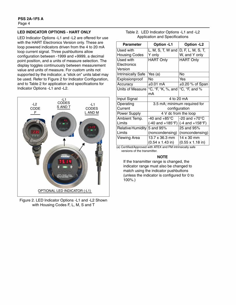
LED INDICATOR OPTIONS - HART ONLY
LED Indicator Options -L1 and -L2 are offered for use with the HART Electronics Version only. These are loop powered indicators driven from the 4 to 20 mA loop current signal. Three pushbuttons allow configuration between -1999 and +9999, a decimal point position, and a units of measure selection. The display toggles continuously between measurement value and units of measure. For custom units not supported by the indicator, a “stick on” units label may be used. Refer to Figure 2 for Indicator Configuration, and to Table 2 for application and specifications for Indicator Options -L1 and -L2.
Figure 2. LED Indicator Options -L1 and -L2 Shownwith Housing Codes F, L, M, S and T
(a) Certified/Approved with ATEX and FM intrinsically safe versions of the transmitter.
NOTEIf the transmitter range is changed, the indicator range must also be changed to match using the indicator pushbuttons (unless the indicator is configured for 0 to 100%.)
OPTIONAL LED INDICATOR (-L1)
CODEF
CODESS AND T CODES
L AND M
-L1-L2-L1
Table 2. LED Indicator Options -L1 and -L2 Application and Specifications
Parameter Option -L1 Option -L2
Used with Housing Codes
L, M, S, T, W and Y only
D, F, L, M, S, T, W, and Y only
Used with Electronics Version
HART Only HART Only
Intrinsically Safe Yes (a) NoExplosionproof No YesAccuracy ±0.01 mA ±0.20 % of SpanUnits of Measure °C, °F, °K, %, and
mA°C, °F, and %
Input Signal 4 to 20 mA Operating Current
3.5 mA; minimum required for configuration
Power Supply 4 V dc from the loopAmbient Temp. Limits
-40 and +85°C(-40 and +185°F)
-20 and +70°C(-4 and +158°F)
Relative Humidity Limits
5 and 95% (noncondensing)
25 and 95% (noncondensing)
Viewing Area 13.7 x 36.3 mm (0.54 x 1.43 in)
14 x 30 mm (0.55 x 1.18 in)

PSS 2A-1F5 APage 5
OPERATING, TRANSPORTATION, AND STORAGE CONDITIONS
(a) Refer to Figure 3 for supply voltage vs. external loop load limitations graph.(b Power supplied by a specific Fieldbus or Profibus power supply, as applicable.(c) For FISCO (Fieldbus Intrinsically Safe Concept) installations, the maximum voltage is 17.5 V dc.(d) Per Lloyd’s specification number 1.(e) 10 m/s2 (1 g) maximum with Housing Codes M, T, or Y (316 ss housings).(f) Not including additional voltage (4 V dc) required for optional LED Indicator. Maximum voltage not to exceed 30 V.(g) Refer to Electrical Safety Specifications section for a restriction in ambient temperature with certain agency approvals/certifications.
NOTETo ensure proper operation, the ambient temperature limits at the housing should not be exceeded. This is particularly relevant when sensors/wells are direct-connected to the housing and very high process temperatures are being measured. The transfer of heat from the process to the housing can be minimized by use of thermowell extensions, or in extreme cases, by using a remote housing installation.
Influence Operative Limits (g)Transportation and Storage
LimitsAmbient Temperature• Transmitter Only• w/LED Indicator Option -L1• w/LED Indicator Option -L2
• -40 and +85°C (-40 and +185°F)(g)• -40 and +85°C (-40 and +185°F)(g)• -20 and +70°C (-4 and +158°F)(g)
• -54 and +85°C (-65 and +185°F)• -54 and +85°C (-65 and +185°F)• -30 and +80°C (-22 and +176°F)
Relative Humidity• Transmitter Only• w/LED Indicator Option -L1• w/LED Indicator Option -L2
• 0 and 95% (Noncondensing)• 5 and 95% (Noncondensing)• 5 and 95% (Noncondensing)
• 0 and 95% (Noncondensing)• 5 and 95% (Noncondensing)• 5 and 95% (Noncondensing)
Supply Voltage• HART (a)• FOUNDATION Fieldbus (b)• Profibus (b)• LED Indicator
• 8 and 30 V dc (f)• 9 and 32 V dc (c)• 9 and 32 V dc (c)• 4 V dc Loop Powered
• Not Applicable• Not Applicable• Not Applicable• Not Applicable
Vibration - Housing Code B 0 and 40 m/s2 (0 and 4 “g”)from 2 to 100 Hz (d)
107 mm (42 in) Drop in shipping container
Vibration - Housing Codes S, T, C, D, W, Y, E, F, L, and M (with or without optional Led Indicator)
19 mm (0.75 in) Double Amplitudefrom 5 to 9 Hz.
0 and 30 m/s2 (0 and 3 “g”) from 9 to 500 Hz (e)
107 mm (42 in) Drop in shipping container
PSS 2A-1F5 APage 6
PERFORMANCE SPECIFICATIONS(1)
Transmitter Accuracy(2) - General ValueFIELDBUS/PROFIBUS
±0.05% of reading for all input types.HART
±0.05% of span for all input types.
Transmitter Accuracy(2) - Basic ValuesPLATINUM RTD INPUT
±0.1°C (±0.18°F)NICKEL RTD INPUT
Fieldbus/Profibus: ±0.15°C (±0.27°F)HART: ±0.2°C (±0.36°F)
TC TYPE E, J, K, L, N, T, AND U INPUT±0.5°C (±0.9°F)
TC TYPE B, R, S, W3, AND W5 INPUT±1.0°C (±1.8°F)
LINEAR RESISTANCE INPUTFieldbus/Profibus: ±0.05 ΩHART: ±0.1 Ω
MILLIVOLT INPUT±10 µV
Accuracy - Cold Junction TemperatureFIELDBUS/PROFIBUS
±0.5°C (±0.9°F)HART
±1.0°C (±1.8°F)
StabilityLong term drift is less than ±0.1% of span per 12 months.
Ambient Temperature Effect - General Values(2)
FIELDBUS/PROFIBUS± 0.002% of reading in °C per °C ± 0.0011% of (°F reading - 32) per °F
HART± 0.005% of span in °C per °C ± 0.0028% of span in °F per °F
Ambient Temperature Effect - Basic Values(2)
RTD AND THERMOCOUPLE INPUTFieldbus/Profibus: ±0.002°C/°C (±0.002°F/°F)HART: ±0.005°C/°C (±0.005°F/°F)
TC TYPE E, J, K, L, N, T, AND U INPUTFieldbus/Profibus: ±0.010°C/°C (±0.010°F/°F)HART: ±0.025°C/°C (±0.025°F/°F)
TC TYPE B, R, S, W3, AND W5 INPUTFieldbus/Profibus: ±0.025°C/°C (±0.025°F/°F)HART: ±0.1°C/°C (±0.1°F/°F)
LINEAR RESISTANCE INPUTFieldbus/Profibus: ±0.002 Ω/°C (±0.0011 Ω/°F)HART: ±5 mΩ/°C (±2.8 mΩ/°F)
MILLIVOLT INPUTFieldbus/Profibus: ±0.2 µV/°C (±0.11 µV/°F)HART: ±0.5 µV/°C (±0.28 µV/°F)
Supply Voltage EffectThe output changes < 0.005% of span for each 1 volt change within the specified voltage range.
EMC Immunity Effect±0.1% of reading per EU (European Union) Directive 89/336/EEC
NAMUR NE 21 A Burst Criterion±1% of span with a test voltage of 2 kV
(1) All performance specifications apply to the transmitter only. Any errors associated with the thermocouple or RTD sensors, any other milli-volt or resistance sensors, or the optional LED Indicators are additive. For performance specifications on Foxboro thermocouples, refer to PSS 1-B6 A, and for Foxboro RTDs refer to PSS 1-1B1 A. Refer to Table 2 for LED Indicator specifications.
(2) Transmitter Accuracy and Ambient Temperature Effect are determined by selecting the greater of the general or basic values listed.

PSS 2A-1F5 APage 7
FUNCTIONAL SPECIFICATIONS
Span and Range Limits - RTD Input
(a) Span limits do not apply with digital Fieldbus or Profibus protocol.(b) Platinum, 100 Ω ; 2-, 3-, or 4-wire RTDs (also see Model Code).(c) Nickel, 100 Ω ; 3-wire RTD (also see Model Code).(d) Transmitter has configurable RTD factor to allow use of Pt 25 through Pt 1000 or Ni 25 through Ni 1000 RTDs (Fieldbus/Profibus
version also accepts Cu 10 through Cu 1000 RTDs).
Span and Range Limits - TC Input
(a) Span limits do not apply with digital Fieldbus or Profibus protocol.
Current Consumption (Fieldbus/Profibus)<11 mA
Response Time1 to 60 s, configurable
Warm-Up Time30 s
Updating Time - Single InputFIELDBUS/PROFIBUS
< 400 msHART
440 ms (660 ms for difference)
Thermocouple Cold Junction CompensationTC cold junction compensated via internal measurement, user-entered constant, or external RTD (2-wire for HART, and 2- or 3-wire for Fieldbus and Profibus).
RTD Cable Resistance Compensation – Transmitter-to-Sensor
4-WIRE RTDTransmitter compensates for cable resistance changes due to ambient temperature changes.
3-WIRE RTDTransmitter compensates for cable resistance changes due to temperature, as long as cables are exposed to the same ambient temperature.
2-WIRE RTDTransmitter compensates for constant cable resistance. User may enter resistance value, or transmitter will measure it during setup.
Sensor Error DetectionAvailable for RTD, TC, and Ohms Inputs(Open and shorted for RTD and Ohms Inputs
and open for TC inputs).
RTD Type
Span Limits HART (a) Range Limits
°C °F °C °FPlatinum, 100 Ω (b)(d) 10 and 1050 18 and 1890 -200 and +850 -328 and +1562Nickel, 100 Ω (c)(d) 10 and 310 18 and 558 -60 and +250 -76 and +482
TC Type
Span Limits HART (a) Range Limits
°C °F °C °FB 100 and 1420 180 and 2556 400 and 1820 752 and 3308E 50 and 1100 90 and 1980 -100 and +1000 -148 and +1832J 50 and 1300 90 and 2340 -100 and +1200 -148 and +2192K 50 and 1552 90 and 2794 -180 and +1372 -292 and +2502L 50 and 1100 90 and 1980 -200 and +900 -328 and +1652N 50 and 1480 90 and 2664 -180 and +1300 -292 and +2372R 100 and 1810 180 and 3258 -50 and +1760 -58 and +3200S 100 and 1810 180 and 3258 -50 and +1760 -58 and +3200T 50 and 600 90 and 1080 -200 and +400 -328 and +752U 50 and 800 90 and 1440 -200 and +600 -328 and 1112
W3 100 and 2300 180 and 4140 0 and 2300 32 and 4172W5 100 and 2300 180 and 4140 0 and 2300 32 and 4172
Span and Range Limits - Linear Resistance Input
Protocol Span Limits Range Limits
Fieldbus (a) 0 and 10 000 ΩProfibus (a) 0 and 10 000 ΩHART 25 and 7 000 Ω 0 and 7 000 Ω(a) Span limits do not apply with Fieldbus or Profibus protocol.
Span and Range Limits - Millivolt Input
Protocol Span Limits Range Limits
Fieldbus (a) -800 and +800 mVProfibus (a) -800 and +800 mVHART 2.5 and 1600 mV -800 and +800 mV(a) Span limits do not apply with Fieldbus or Profibus protocol.
PSS 2A-1F5 APage 8
FUNCTIONAL SPECIFICATIONS (Cont.)
Input Resistance10 MΩ for Fieldbus, Profibus, and HART
Resistance Temperature Detectors (RTDs)(1)
RTD TYPEPt100; 3-wire; ASTM-B Standard
Accuracy, alpha = 0.00385Pt100; 3- and 4-wire; ASTM-A High Accuracy,
alpha = 0.00385Ni100; 3-wire; DIN 43760
RTD SHEATH316 ss, -200 and +480°C (-320 and +900°F)Inconel, -200 and +650°C (-320 and +1200°F)
SHEATH SEALANTEpoxy compound applied at open end of sheath to prevent entry of moisture
MINIMUM IMMERSION90 mm (3.5 in) is required to minimize thermal conduction errors
RESPONSE TIME5 s maximum for a 63% recovery; based on a step change in temperature of bare sensor starting at room temperature of 25°C (77°F) to immersion in 100°C (212°F) water stirred at 1 m/s (3 ft/s)
EXTERNAL CONNECTING WIREColor coded leads; stranded 0.50 mm2 or 22 AWG; ptfe insulation
Thermocouples (TCs)(2)
TC TYPE (FOXBORO TCs PER ASTM E608)Base metal types E, J, K, L, N, T, and UPlatinum metal types B, R, and STungsten metal types W3 and W5
TC SHEATH316 ss, -200 and +900°C (-320 and +1650°F)Inconel, -200 and +1150°C (-320 and +2100°F)
SHEATH SEALANTEpoxy compound applied at open end of sheath to prevent entry of moisture
MINIMUM IMMERSION90 mm (3.5 in) is required to minimize thermal conduction errors
RESPONSE TIME5 s maximum for a 63% recovery; based on a step change in temperature of bare sensor starting at room temperature of 25°C (77°F) to immersion in 100°C (212°F) water stirred at 1 m/s (3 ft/s)
EXTERNAL CONNECTING WIREColor coded leads; stranded 0.080 mm2 or 20 AWG; fiberglass insulation
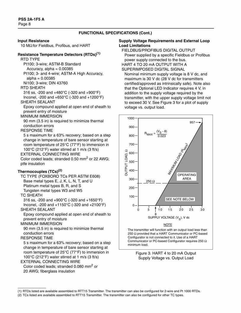
Supply Voltage Requirements and External Loop Load Limitations
FIELDBUS/PROFIBUS DIGITAL OUTPUTPower supplied by a specific Fieldbus or Profibus power supply connected to the bus.
HART 4 TO 20 mA OUTPUT WITH A SUPERIMPOSED DIGITAL SIGNAL
Nominal minimum supply voltage is 8 V dc, and maximum is 30 V dc (28 V dc for transmitters certified/approved as intrinsically safe). Note also that the Optional LED Indicator requires 4 V, in addition to the supply voltage required by the transmitter, with the upper supply voltage limit not to exceed 30 V. See Figure 3 for a plot of supply voltage vs. output load.
Figure 3. HART 4 to 20 mA OutputSupply Voltage vs. Output Load
(1) RTDs listed are available assembled to RTT15 Transmitter. The transmitter can also be configured for 2-wire and Pt 1000 RTDs.(2) TCs listed are available assembled to RTT15 Transmitter. The transmitter can also be configured for other TC types.
1000
900
800
700
600
500
400
300
200
100
0
8
0 5 1 0 1 5 2 0 2 5 3 0
SUPPLY VOLTAGE (VS), V dc
OU
TP
UT
LO
AD
, Ω
250 Ω
RMAX =
MA
XIM
UM
LO
AD
(RM
AX
)
OPERATINGAREA
957
SEE NOTE BELOW
(VS - 8)
0.023
The transmitter will function with an output load less than250 Ω provided that a HART Communicator or PC-based Configurator is not connected to it. Use of a HART Communicator or PC-based Configurator requires 250 Ω minimum load.
NOTE

PSS 2A-1F5 APage 9
FUNCTIONAL SPECIFICATIONS (Cont.)
ThermowellsThe wells listed in the Model Code are popular selections for industrial use. In addition, Invensys Foxboro offers other high quality, polished wells in a variety of configurations, materials, and sizes. Most application requirements can be met by choosing from the wide selection offered. Specify Thermowell Code TX and see PSS 3-3C1 A for Type W Thermowells, and PSS 3-3D1 A for Type T Thermowells, or contact Invensys Foxboro. See Figure 4 for a small sample of wells available.
Figure 4. Typical W-Series and T-SeriesThermowells Shown
HART (Version -T) Communications4 TO 20 mA ANALOG MODE
Analog output signal is updated 30 times per second. A minimum loop load of 250 ohms is required. See Table 3 for communication parameters.
MULTIDROP MODE (FIXED CURRENT)This Mode supports communications with up to 15 transmitters on a single pair of signal/power wires. The output signal is updated 4 times/second. A minimum loop load of 250 ohms is required. See Table 3 for communication parameters.
FOUNDATION Fieldbus (Version -F) Communications
This serial, two-way communication system runs at 31.25 kbits/s. The digital output signal is superimposed on the dc power signal on the bus, and controlled by a strict cycle schedule and protocol. Supply voltage, 9 to 32 V dc, is by a specific Fieldbus power source. Current consumption is 19.5 mA. The maximum number of devices on a non-intrinsically safe bus is 32. For intrinsically safe bus systems the maximum number is 6. See Table 3 for communication parameters.
PROFIBUS (Version -P) CommunicationsThis all digital, serial, two-way communication systems interconnects field devices, such as transmitters, actuators, and controllers. It is a vendor-independent, open fieldbus standard conforming to international standards. The PROFIBUS Process Automation (PA) profile, used with these transmitters, defines the device parameters and behavior of typical field devices, and facilitates device interchangeability and vender independent operation. Supply voltage is 9 to 32 V dc, with a current consumption of 19.5 mA. As with FOUNDATION Fieldbus, the maximum number of devices on a non-intrinsically safe bus is 32. For intrinsically safe bus systems, the maximum number is 6. See Table 3 for communication parameters.
(a) Total bus length including all spurs. Maximum spur length is 120 m (395 ft). For hybrid installations, maximum IS spur length is dependant on the field barrier used. For intrinsically safe bus installations, maximum spur length is 30 m (98 ft).
.
W-PFS W-PDT
TT
TF
TS
TW
Table 3. Communication Parameters - HART, FOUNDATION Fieldbus, and Profibus Protocols
Parameter
HART Fieldbus Profibus
Analog Mode Multidrop Mode Digital Digital
Remote ConfiguratorHART Communicator
or PC-based ConfiguratorPC or Fieldbus Host PC or Profibus Host
Communication Rate 1200 baud 1200 baud 31.25 kbits/s 31.25 kbits/sCommunication Distance (Rated)
3050 m (10 000 ft) 1525 m (5000 ft) 1900 m (6235 ft) (a) 1900 m (6235 ft) (a)

PSS 2A-1F5 APage 10
FUNCTIONAL SPECIFICATIONS (Cont.)
Figure 5. Typical Installation Topologies (FOUNDATION Fieldbus)
Figure 6. Typical Profibus Installation Topology
Figure 7. HART 4 to 20 mA Output Block Diagram
(One Transmitter)
Figure 8. HART Multidrop Block Diagram
(Up to Fifteen Transmitters)
FIELDBUSINTERFACEELECTRONICS
JUNCTION BOX
BUS WITH SPURS DAISY CHAIN TREE
HOSTCOMPUTER
NOTETerminators and Power Supply not shown
Fieldbus - 31.25 kbits/s
OTHERMEASUREMENT
DEVICES(2-WIRE)
RS-485UP TO 12 MBits/s
FIELDBUS/PROFIBUSCERTIFIED HOST
HOST
RTT15
PROFIBUS DP (COMMUNICATION PROFILE)
IEC 1158-231.25 kBits/s
SEGMENTCOUPLER
PROFIBUSTERMINATORS
AND POWER SUPPLYNOT SHOWN
NOTE
RS-485DEVICES
PROFIBUS PA (PROCESS AUTOMATION PROFILE)
+
21
36
45
INDICATORPOWERSUPPLY
RTT15TRANSMITTER
CONTROLLEROR RECORDER
+
+
+
+ 250 MINIMUM
HARTCOMMUNICATOR,OR PC-BASEDCONFIGURATOR
+
+3
21
36
45
HARTCOMPATIBLE
MODEM
GAUGEPRESSXMTR
POWERSUPPLY
d/p CellXMTR
RTT15TRANSMITTER
250 ΩMIN.
HOSTCOMPUTER
+
+3
21
36
45

PSS 2A-1F5 APage 11
PHYSICAL SPECIFICATIONS
Transmitter Housings
(a) Not applicable; the basic module, although encapsulates, has exposed terminals not protected from the environment.
(b) The basic module is typically used for replacement and spares purposes; it can also be mounted to a surface or to a DIN rail using a clip (Option -D1).
(c) Optional conduit threads or thread adapters available; see Model Code.
(d) Two wiring entrances on housing.
(e) Surface or pipe mounted using mounting set options -M1 or -M2.
HousingCode
Material and Finish
IEC/NEMA Rating
Explosionproofand
FlameproofMounting
Configuration
Field Wiring Entrances on
Housing
Housing Cover Gasket
B Encapsulated plastic
N/A(a)
NO Basic Module (b)(DIN Form B pkg.)
None NotApplicable
C Low copper aluminum alloy
IP65NEMA 4
NO Weatherproof connection head with integral bare sensor
1/2 NPT(c)
O-RingBuna N
D Low copper aluminum alloy; painted
IP65NEMA 4X
YES Explosionproof connection head with integral bare sensor
1/2 NPT(c)
GasketBuna N
E Low copper aluminum alloy
IP65NEMA 4
NO Weatherproof connection head with integral sensor and well
1/2 NPT(c)
O-RingBuna N
F Low copper aluminum alloy; painted
IP65NEMA 4X
YES Explosionproof connection head with integral sensor and well
1/2 NPT(c)
GasketBuna N
L Low copper aluminum alloy; epoxy coated
IP65NEMA 4X
YES Universal housing with integral sensor and well
1/2 NPT(c)
O-RingBuna N
M Stainless steel IP65NEMA 4X
YES Universal housing with integral sensor and well
1/2 NPT(c)
O-RingBuna N
S Low copper aluminum alloy; epoxy coated
IP65NEMA 4X
YES Universal housing for surface or pipe mounting, remote sensor (e)
1/2 NPT(c)(d)
O-RingBuna N
T Stainless steel IP65NEMA 4X
YES Universal housing for surface or pipe mounting, remote sensor (e)
1/2 NPT(c)(d)
O-RingBuna N
W Low copper aluminum alloy; epoxy coated
IP65NEMA 4X
YES Universal housing with integral bare sensor
1/2 NPT(c)
O-RingBuna N
Y Stainless steel IP65NEMA 4X
YES Universal housing with integral bare sensor
1/2 NPT(c)
O-RingBuna N

PSS 2A-1F5 APage 12
PHYSICAL SPECIFICATIONS (Cont.)
MountingThe basic transmitter module can be mounted to a DIN rail using the optional mounting clip and self-tapping screw provided by Invensys Foxboro. The basic module can also be mounted to a surface using user-supplied hardware. See DIMENSIONS - NOMINAL section.
The universal housing (without sensor) can be remote mounted to a surface or nominal DN 50 or 2-in pipe using the optional mounting bracket. See DIMENSIONS - NOMINAL section.
The connection head housings are sensor or thermowell mounted. See DIMENSIONS - NOMINAL section.
Electrical ConnectionsThere are six terminals on the basic module for input and output connections. Four terminals are for RTD, TC, ohm, or mV sensor inputs, and two terminals are for measurement output. With HART, the two output terminals are marked + and –; while with Fieldbus/Profibus, the two output terminals are polarity independent, and therefore not marked. Refer to DIMENSIONS - NOMINAL section.
DimensionsRefer to DIMENSIONS - NOMINAL section. Also refer to Dimensional Print DP 020-462.
Approximate Transmitter Mass
(a) Basic transmitter module.(b) Surface or pipe mount housing; remote sensor.(c) Includes module, but bare sensor mass and connecting hardware not included.(d) Includes module, but sensor and well mass and connecting hardware not included.(e) Optional LED Indicator available with HART versions only.(f) Indicator Option -L2 only (Option -L1 not available with Housing Codes D and F).
Housing CodeHousing Material
Approximate Mass
Standard With Optional LED (e)
kg lb kg lb
B - Basic Module (a) N/A 0.05 0.11 N/A N/AC - Weatherproof Head (c) Aluminum 0.4 0.8 N/A N/AD - Explosionproof Head (c) Aluminum 0.7 1.5 0.9 2.0 (f)E - Weatherproof Head (d) Aluminum 0.4 0.8 N/A N/AF - Explosionproof Head (d) Aluminum 0.7 1.5 0.9 2.0 (f)L - Universal Housing (d) Aluminum 1.4 3.1 1.6 3.6M - Universal Housing (d) 316 ss 3.2 7.1 3.7 8.2S - Universal Housing (b) Aluminum 1.4 3.1 1.6 3.6T - Universal Housing (b) 316 ss 3.2 7.1 3.7 8.2W - Universal Housing (c) Aluminum 1.4 3.1 1.6 3.6Y - Universal Housing (c) 316 ss 3.2 7.1 3.7 8.2
PSS 2A-1F5 APage 13
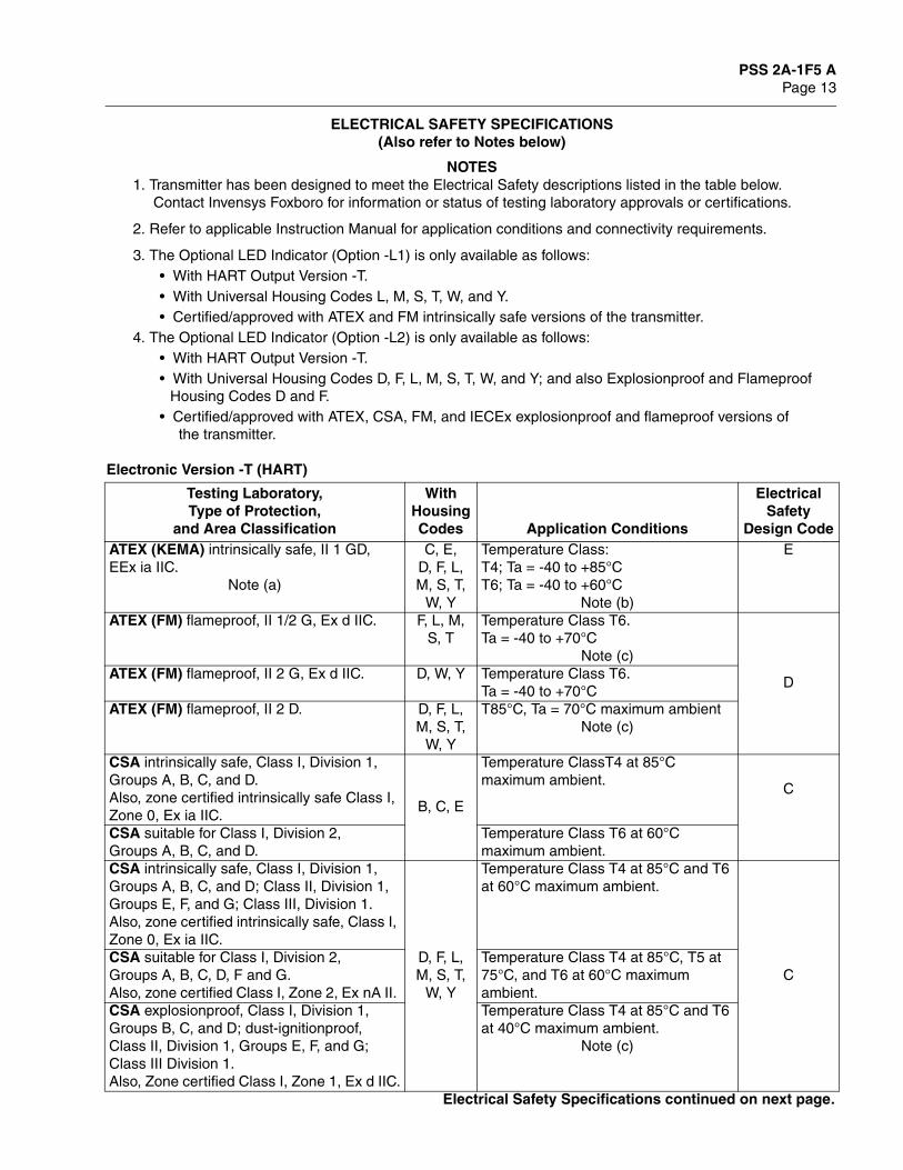
ELECTRICAL SAFETY SPECIFICATIONS(Also refer to Notes below)
NOTES1. Transmitter has been designed to meet the Electrical Safety descriptions listed in the table below.
Contact Invensys Foxboro for information or status of testing laboratory approvals or certifications.
2. Refer to applicable Instruction Manual for application conditions and connectivity requirements.
3. The Optional LED Indicator (Option -L1) is only available as follows:• With HART Output Version -T.• With Universal Housing Codes L, M, S, T, W, and Y.• Certified/approved with ATEX and FM intrinsically safe versions of the transmitter.
4. The Optional LED Indicator (Option -L2) is only available as follows:• With HART Output Version -T.• With Universal Housing Codes D, F, L, M, S, T, W, and Y; and also Explosionproof and Flameproof
Housing Codes D and F.• Certified/approved with ATEX, CSA, FM, and IECEx explosionproof and flameproof versions of
the transmitter.
Electronic Version -T (HART)
Testing Laboratory,Type of Protection,
and Area Classification
With Housing Codes Application Conditions
Electrical Safety
Design CodeATEX (KEMA) intrinsically safe, II 1 GD,EEx ia IIC.
Note (a)
C, E,D, F, L, M, S, T,
W, Y
Temperature Class:T4; Ta = -40 to +85°CT6; Ta = -40 to +60°C
Note (b)
E
ATEX (FM) flameproof, II 1/2 G, Ex d IIC. F, L, M,S, T
Temperature Class T6.Ta = -40 to +70°C
Note (c)
DATEX (FM) flameproof, II 2 G, Ex d IIC. D, W, Y Temperature Class T6.
Ta = -40 to +70°CATEX (FM) flameproof, II 2 D. D, F, L,
M, S, T, W, Y
T85°C, Ta = 70°C maximum ambientNote (c)
CSA intrinsically safe, Class I, Division 1, Groups A, B, C, and D. Also, zone certified intrinsically safe Class I, Zone 0, Ex ia IIC.
B, C, E
Temperature ClassT4 at 85°C maximum ambient.
C
CSA suitable for Class I, Division 2, Groups A, B, C, and D.
Temperature Class T6 at 60°C maximum ambient.
CSA intrinsically safe, Class I, Division 1, Groups A, B, C, and D; Class II, Division 1, Groups E, F, and G; Class III, Division 1. Also, zone certified intrinsically safe, Class I, Zone 0, Ex ia IIC.
D, F, L, M, S, T,
W, Y
Temperature Class T4 at 85°C and T6 at 60°C maximum ambient.
CCSA suitable for Class I, Division 2, Groups A, B, C, D, F and G. Also, zone certified Class I, Zone 2, Ex nA II.
Temperature Class T4 at 85°C, T5 at 75°C, and T6 at 60°C maximum ambient.
CSA explosionproof, Class I, Division 1, Groups B, C, and D; dust-ignitionproof, Class II, Division 1, Groups E, F, and G; Class III Division 1. Also, Zone certified Class I, Zone 1, Ex d IIC.
Temperature Class T4 at 85°C and T6 at 40°C maximum ambient.
Note (c)
Electrical Safety Specifications continued on next page.

PSS 2A-1F5 APage 14
ELECTRICAL SAFETY SPECIFICATIONS (Cont.)(Also refer to Notes above)
Electronic Version -T (HART) (Cont.)
(a) With the -L1 Indicator Option, the type of protection is II 1 G, Ex ia IIC. Also not available with Housing Codes C, E, D, and F.
(b) With the -L1 Indicator Option, replace Temperature Class T6 with Temperature Class T5.
(c) Certifications do not apply for Housing Codes F, L, or M if well is not supplied with transmitter (Code NA).
(d) Also includes Group A for Housing Codes D and F.
(e) With -L1 Indicator Option only.
Electronic Version -F and -P (FOUNDATION Fieldbus and PROFIBUS)
Testing Laboratory,Type of Protection,
and Area Classification
With Housing Codes Application Conditions
Electrical Safety
Design CodeFM intrinsically safe, Class I, Division 1, Groups A, B, C, and D. (e)
L, M, S, T, W, Y
Temperature Class T4 at 85°C, and T5 at 60°C maximum ambient. (e)
F
FM intrinsically safe, Class I, Division 1, Groups A, B, C, and D.
B, C, E
Temperature Class T4 at 85°C, and T6 at 60°C maximum ambient.
FM zone certified intrinsically safe, Class I, Zone 0, AEx ia IIC.
Temperature Class T4 at 85°C maximum ambient.
FM nonincendive, Class I, Division 2, Groups A, B, C, and D.
Temperature Class T4 at 85°C maximum ambient.
FM intrinsically safe, Class I, Division 1, Groups A, B, C, and D; Class II, Division 1, Groups E, F, and G; Class III, Division 1.
D, F, L, M, S, T,
W, Y
Temperature Class T4 at 85°C, and T6 at 60°C maximum ambient.
FM zone certified intrinsically safe, Class I, Zone 0, AEx ia IIC.
Temperature Class T4 at 85°C maximum ambient.
FM nonincendive Class I, Division 2, Groups A, B, C, and D; suitable for Class II, Division 2, Groups F and G.
Temperature Class T4 at 85°C maximum ambient.
FM explosionproof, Class I, Division 1, Groups B, C, and D; dust-ignitionproof, Class II, Division 1, Groups E, F, and G; Class III Division 1.
Note (d)
Temperature Class T5 at 85°C, and T6 at 70°C maximum ambient.
Note (c)
IECEx flameproof, Ex d IIC. L, M, S, T, W, Y
Temperature Class T6. Ta = 70°C. V
Testing Laboratory,Type of Protection,
and Area Classification
With Housing Codes Application Conditions
Electrical Safety
Design CodeATEX (KEMA) intrinsically safe, II 1 GD or II 2 (1) GD, EEx ia IIC or EEx ib [ia] IIC.
All Temperature Class T4 to T6.Ta = -40 to +85°C
E
ATEX (FM) flameproof, II 1/2 G, Ex d IIC. F, L, M,S, T, Y
Temperature Class T6.Ta = -40 to +70°C
Note (a)
DATEX (FM) flameproof, II 2 G, Ex d IIC. D, W, Y Temperature Class T6.
Ta = -40 to +70°C Note (a)
ATEX (FM) flameproof, II 2 D. D, F, L, M, S, T,
W, Y
T85°C, Ta = 70°C maximum ambient.Note (a)
Electrical Safety Specifications continued on next page.

PSS 2A-1F5 APage 15
ELECTRICAL SAFETY SPECIFICATIONS (Cont.)(Also refer to Notes above)
Electronic Version -F and -P (FOUNDATION Fieldbus and PROFIBUS) (Cont.)
(a) Explosionproof/Flameproof certification not available for Housing Codes F, L, or M if well is not supplied with transmitter (Code NA).
(b) Also includes Group A for Housing Codes D and F.
Testing Laboratory,Type of Protection,
and Area Classification
With Housing Codes Application Conditions
Electrical Safety
Design CodeCSA intrinsically safe, Class I, Division 1, Groups A, B, C, and D. Also, zone certified intrinsically safe Class I, Zone 0, Ex ia IIC.
B, C, E
Temperature Class T4 at 85°C maximum ambient.
C
CSA suitable for Class I, Division 2, Groups A, B, C, and D.
Temperature Class T4 at 85°C maximum ambient.
CSA intrinsically safe, Class I, Division 1, Groups A, B, C, and D; dust-ignitionproof, Class II, Division 1, Groups E, F, and G; Class III, Division 1. Also, zone certified intrinsically safe, Class I, Zone 0, Ex ia IIC, and Class I, Zone 1, Ex ib IIC.
D, F, L, M, S, T,
W, Y
Temperature Class T4 at 85°C, and T6 at 60°C maximum ambient.
CCSA suitable for Class I, Division 2, Groups A, B, C, D, F and G. Also, zone certified Class I, Zone 2, Ex nA II.
Temperature Class T4 at 85°C, T5 at 75°C, and T6 at 60°C maximum ambient.
CSA explosionproof, Class I, Division 1, Groups B, C, and D; dust-ignitionproof, Class II, Division 1, Groups E, F, and G; Class III Division 1. Also, zone certified Class I, Zone 1, Ex d IIC.
D, F, L, M, S, T,
W, Y
Temperature Class T4 at 85°C, and T6 at 40°C maximum ambient.
Note (a)
FM FISCO field device intrinsically safe for Class I, Division 1, Groups A, B, C, and D. Also zone certified intrinsically safe Class I, Zone 0, AEx ia IIC, and Class I, Zone 1, AEx ib IIC.
B, C, E
Temperature Class T4 at 85°C maximum ambient.
F
FM FNICO field device nonincendive for Class I, Division 2, Groups A, B, C, and D. FM FNICO field device intrinsically safe for Class I, Division 1, Groups A, B, C, and D; Class II, Division 1, Groups E, F, and G.Also zone certified intrinsically safe Class I, Zone 0, AEx ia IIC, and Class I, Zone 1, AEx ib IIC.
D, F, L, M, S, T,
W, Y
Temperature Class T4 at 85°C maximum ambient.
FM FNICO field device nonincendive for Class I, Division 2, Groups A, B, C, and D; Class II, Division 2, Groups F and G; Class III, Division 2.FM explosionproof, Class I, Division 1, Groups B, C, and D; dust-ignitionproof, Class I, Division 1, Groups E, F, and G; Class III, Division 1.Also, zone certified Class I, Zone 1, AEx d IIC.
Note (b)
D, F, L, M, S, T,
W, Y
Temperature Class T5 at 85°C, and T6 at 70°C maximum ambient.
Note (a)
IECEx flameproof, Ex d IIC L, M, S, T, W, Y
Temperature Class T6. Ta = 70°C. V

PSS 2A-1F5 APage 16
MODEL CODES
Model Code - Basic Module Code BRemote sensors not provided but can be ordered separately
Description ModelI/A Series Temperature Transmitter RTT15
Output VersionIntelligent; Digital HART and 4 to 20 mA dc (Version -T) -TIntelligent; Digital FOUNDATION Fieldbus H1 (Version -F) -FIntelligent; Digital Profibus PA (Version -P) -P
Input Configuration (a)Single Input; Configured for One Sensor 1Dual Input; Configured for Average of two 2-wire sensors of same type (b) 4Dual Input; Configured for Difference of two 2-wire sensors of same type (b) 5Dual Input; Configured for Redundancy of two 2-wire sensors of same type (b) 6
(Not available with Output Version -T/HART)
Housing and Sensor Mounting (Basic Module - No Housing)Basic Module used for Surface Mount, DIN Rail Mount, or Module Replacement.Material Certificate (AS Reference CERT-C) not offered with this selection.
B
Sensor LengthNone - Sensor ordered separately N
Measurement Input Type (Software Selectable) (c)Thermocouple, Type B, Platinum-Rhodium BThermocouple, Type E, Chromel-Constantan EThermocouple, Type J, Iron-Constantan JThermocouple, Type K, Chromel-Alumel KThermocouple, Type L, Iron-Copper/Nickel LThermocouple, Type N, Nicrosil-Nisil N
Thermocouple, Type R, Platinum-Rhodium RThermocouple, Type S, Platinum-Rhodium SThermocouple, Type T, Copper-Constantan TThermocouple, Type U, Copper-Copper/Low Nickel UThermocouple, Type W3, Tungsten - Rhenium 3Thermocouple, Type W5, Tungsten - Rhenium 5
RTD, Platinum, 2-wire, 100 Ω, IEC 751 (ASTM-B Standard Accuracy), 316 ss Sheath 2RTD, Platinum, 3-wire, 100 Ω, IEC 751 (ASTM-B Standard Accuracy), 316 ss Sheath (d) QRTD, Platinum, 4-wire, 100 Ω, IEC 751 (ASTM-B Standard Accuracy), 316 ss Sheath (d) 4RTD, Platinum, 3-wire, 100 Ω, IEC 751 (ASTM-A High Accuracy), 316 ss Sheath (d) ARTD, Platinum, 4-wire, 100 Ω, IEC 751 (ASTM-A High Accuracy), 316 ss Sheath (d) 6RTD, Nickel, 3-wire, 100 Ω, DIN 43760, 316 ss Sheath (d) I
Ohm Input OMillivolt Input M
Model Code continued on next page
HOUSINGCODE B
HART MODULESHOWN

PSS 2A-1F5 APage 17
(a) Input configuration can be changed in the field by changing wiring terminations and reconfiguring.
(b) For Dual Input with different type sensors (Output Versions -F and -P only), specify Input Configuration Code 1 and reconfigure the transmitter after shipment, or specify the -C2 option.
(c) Transmitter is configured for measurement type specified, whether sensor is included or not. User can change configuration to a different type using the appropriate configurator for selected protocol.
(d) Measurement input types Q, 4, A, 6, and I not available with Dual Input Configuration Codes 4, 5, and 6. User Configuration or -C2 Option can be used for dual input of one three-wire RTD and one TC (Output Versions -F and -P only).
(e) Basic module is attached to mounting clip with a self-tapping screw, and shipped assembled for snapping onto the DIN rail.
(f) Standard transmitter is shipped with a paper instruction manual that describes installation, operation, and configuration, and a CD that includes all pertinent documentation such as Parts Lists, Dimensional Prints, and more detailed instructions.
Description (Cont.) Model
Thermowell Assembled to HousingNo Well, or Well is supplied separately NA
Electrical Safety (see Electrical Safety Specifications Section for more details)ATEX, Intrinsically Safe, EEx ia IIC ECSA, Intrinsically Safe and Division 2 CFM, Intrinsically Safe and Division 2 F
Optional SelectionsCustom Database Configuration (requires C2 Form filled out with all data specified) -C2Clip and Self-Tapping Screw provided to mount the Basic Module to a DIN Rail (e) -D1Adapter Plate and Screws to allow mounting the RTT Basic Transmitter Module into existing -D3
E93, E94, 893, and RTT10 Transmitter housings.Omit Paper Instruction Manual and CD (f) -K1
Example: RTT15-T1BNJNAC-C2D1
MODEL CODES (Continued)
Model Code - Basic Module Code BRemote sensors not provided but can be ordered separately (Continued)

PSS 2A-1F5 APage 18
MODEL CODES (Continued)
Model Code - Housing Codes S and TRemote sensors not provided but can be ordered separately
Description (Cont.) ModelI/A Series Temperature Transmitter RTT15
Output VersionIntelligent; Digital HART and 4 to 20 mA dc (Version -T) -TIntelligent; Digital FOUNDATION Fieldbus H1 (Version -F) -FIntelligent; Digital Profibus PA (Version -P) -P
Input Configuration (a)Single Input; Configured for One Sensor 1Dual Input; Configured for Average of two 2-wire sensors of same type (b) 4Dual Input; Configured for Difference of two 2-wire sensors of same type (b) 5Dual Input; Configured for Redundancy of two 2-wire sensors of same type (b) 6
(Not available with Output Version -T/HART)
Housing and Sensor Mounting (Housing for Surface or Pipe Mounting)Universal Housing, Aluminum, for use with remote sensor S
Remote Sensor ordered separatelyUniversal Housing, 316 ss, for use with remote sensor T
Remote Sensor ordered separately
Sensor LengthNone - Sensor ordered separately N
Measurement Input Type (Software Selectable) (c)Thermocouple, Type B, Platinum-Rhodium BThermocouple, Type E, Chromel-Constantan EThermocouple, Type J, Iron-Constantan JThermocouple, Type K, Chromel-Alumel KThermocouple, Type L, Iron-Copper/Nickel LThermocouple, Type N, Nicrosil-Nisil N
Thermocouple, Type R, Platinum-Rhodium RThermocouple, Type S, Platinum-Rhodium SThermocouple, Type T, Copper-Constantan TThermocouple, Type U, Copper-Copper/Low Nickel UThermocouple, Type W3, Tungsten - Rhenium 3Thermocouple, Type W5, Tungsten - Rhenium 5
RTD, Platinum, 2-wire, 100 Ω, IEC 751 (ASTM-B Standard Accuracy), 316 ss Sheath 2RTD, Platinum, 3-wire, 100 Ω, IEC 751 (ASTM-B Standard Accuracy), 316 ss Sheath (d) QRTD, Platinum, 4-wire, 100 Ω, IEC 751 (ASTM-B Standard Accuracy), 316 ss Sheath (d) 4RTD, Platinum, 3-wire, 100 Ω, IEC 751 (ASTM-A High Accuracy), 316 ss Sheath (d) ARTD, Platinum, 4-wire, 100 Ω, IEC 751 (ASTM-A High Accuracy), 316 ss Sheath (d) 6RTD, Nickel, 3-wire, 100 Ω, DIN 43760 (d) I
Ohm Input OMillivolt Input M
Model Code continued on next page
HOUSINGCODES S AND T

PSS 2A-1F5 APage 19
(a) Input configuration can be changed in the field by changing wiring terminations and reconfiguring.
(b) For Dual Input with different type sensors (Output Versions -F and -P only), specify Input Configuration Code 1 and reconfigure the transmitter after shipment, or specify the -C2 option.
(c) Transmitter is configured for measurement type specified, whether sensor is included or not. User can change configuration to a different type using the appropriate configurator for selected protocol.
(d) Measurement input types Q, 4, A, 6, and I not available with Dual Input Configuration Codes 4, 5, and 6. User Configuration or -C2 Option can be used for dual input of one three-wire RTD and one TC (Output Versions -F and -P only).
(e) Options -A2 and -A3 not available with Electrical Safety Codes C and F explosionproof installations.
(f) For mounting transmitter to a surface or nominal DN 50 or 2-in pipe.
(g) Refer to Table 2 for Indicator applications and specifications.
(h) Standard transmitter is shipped with a paper instruction manual that describes installation, operation, and configuration, and a CD that includes all pertinent documentation such as Parts Lists, Dimensional Prints, and more detailed instructions.
Description (Cont.) Model
Thermowell Assembled to HousingNo Well or Well ordered separately NA
Electrical Safety (see Electrical Safety Specifications Section for more details)ATEX, Intrinsically Safe, EEx ia IIC EATEX, Flameproof, EEx d IIC (not available with Option -L1) DCSA Intrinsically Safe, Explosionproof, and Division 2 (not available with Option -L1) CFM, Intrinsically Safe, Explosionproof, and Nonincendive FIECEx, Flameproof, Ex d IIC (not available with Option -L1) V
Optional Selections - Housing FeaturesCustody Transfer Lock and Seal -A1PG 13.5 Conduit Thread (in lieu of 1/2 NPT) (e) -A2
(Not available with Option -A3)Metric Conduit Thread Adapter (1/2 NPT to M20 x 1.5) (e) -A3
(Not available with Option -A2)
Optional Selections - Mounting SetsCarbon Steel (with finish) Mounting Set (f) -M1Stainless Steel (with finish) Mounting Set (f) -M2
Optional Selection - LED Indicator (with Output Version -T only)Loop Powered Indicator - Intrinsically Safe (g)With ATEX and FM intrinsically safe versions of the transmitter.
-L1
Loop Powered Indicator - Explosionproof (g)With ATEX, CSA, FM, and IECEx explosionproof/flameproof versions of the transmitter.
-L2
Optional Selections - MiscellaneousCustom Database Configuration (Requires C2 Form filled out with all data specified) -C2Omit Paper Instruction Manual and CD (h) -K1
Example: RTT15-T1SNJNAC-A2M2C2
MODEL CODES (Continued)
Model Code - Housing Codes S and TRemote sensors not provided but can be ordered separately (Continued)

PSS 2A-1F5 APage 20
MODEL CODES (Continued)
Model Code - Housing Codes C, D, W, and YIntegral bare sensors provided
Description ModelI/A Series Temperature Transmitter RTT15
Output VersionIntelligent; Digital HART and 4 to 20 mA dc (Version -T) -TIntelligent; Digital FOUNDATION Fieldbus H1 (Version -F) -FIntelligent; Digital Profibus PA (Version -P) -P
Input Configuration (a)Single Input; Configured for One Sensor 1
Housing and Sensor Mounting (Integral Bare Sensors)Weatherproof Connection Head, aluminum; with Integral Bare Sensor CExplosionproof Connection Head, aluminum; with Integral Bare Sensor DUniversal Housing, aluminum; with Integral Bare Sensor WUniversal Housing, 316 ss; with Integral Bare Sensor Y
Sensor Length - Dimension A (b)2 in (50 mm), Sensor included A2.5 in (64 mm), Sensor included B3 in (76 mm), Sensor included C3.5 in (89 mm), Sensor included D4 in (102 mm), Sensor included E4.5 in (114 mm), Sensor included F
5 in (127 mm), Sensor included G5.5 in (146 mm), Sensor included H6 in (152 mm), Sensor included J7 in (178 mm), Sensor included K8 in (203 mm), Sensor included L9 in (229 mm), Sensor included M10 in (254 mm), Sensor included P
11 in (279 mm), Sensor included Q12 in (305 mm), Sensor included R18 in (457 mm), Sensor included S24 in (610 mm), Sensor included T30 in (762 mm), Sensor included U36 in (914 mm), Sensor included VCustom Lengths between 2 and 120 in (50 mm and 3 m), Sensor included X
Model Code continued on next page
HOUSING CODE C HOUSING CODE D HOUSING CODES W AND Y

PSS 2A-1F5 APage 21
(a) Input configuration can be changed in the field by changing wiring terminations and reconfiguring.(b) Quantity of one Foxboro sensor that is listed under Measurement Input Type. Length is Dimension A as shown in the Dimensions-
Nominal section. Dimension A is bare element insertion length.(c) Transmitter is configured for measurement type specified, whether sensor is included or not. User can change configuration to a
different type using the appropriate configurator for selected protocol.(d) Option -A2 only available with Electrical Safety Codes D and E.(e) Standard transmitter is shipped with a paper instruction manual that describes installation, operation, and configuration, and a CD
that includes all pertinent documentation such as Parts Lists, Dimensional Prints, and more detailed instructions.(f) Refer to Table 2 for Indicator applications and specifications. (g) Inconel sheath is 0.250 in (6.35 mm) outside diameter, and provides a moisture resistant assembly. The sheath O.D. is designed to
fit into a well I.D. of 0.260 in (6.60 mm).
Description (Cont.) Model
Measurement Input Type (Software Selectable) (c)Thermocouple, Type E, Chromel-Constantan EThermocouple, Type J, Iron-Constantan JThermocouple, Type K, Chromel-Alumel KThermocouple, Type T, Copper-Constantan T
RTD, Platinum, 3-wire, 100 Ω, IEC 751 (ASTM-B Standard Accuracy), 316 ss Sheath QRTD, Platinum, 4-wire, 100 Ω, IEC 751 (ASTM-B Standard Accuracy), 316 ss Sheath 4RTD, Platinum, 3-wire, 100 Ω, IEC 751 (ASTM-A High Accuracy), 316 ss Sheath ARTD, Platinum, 4-wire, 100 Ω, IEC 751 (ASTM-A High Accuracy), 316 ss Sheath 6
Ohm Input OMillivolt Input M
Thermowell Assembled to HousingNo Well NA
Electrical Safety (see Electrical Safety Specifications Section for further details)Supplied without Agency Approval/Certification (with Housing Codes C and D only) ZATEX, Intrinsically Safe; EEx ia IIC EATEX, Flameproof; EEx d IIC (not available with Option -L1) DCSA, Intrinsically Safe, Explosionproof, and Division 2 (not available with Option -L1) CFM, Intrinsically Safe, Explosionproof, and Nonincendive FIECEx, Flameproof, Ex d IIC (not available with Housing Codes C and D, or Option -L1) V
Optional Selections - Housing FeaturesCustody Transfer Lock and Seal (with Housing Codes W and Y only) -A1PG 13.5 Conduit Thread (in lieu of 1/2 NPT), (with Housing Codes W and Y only) (d) -A2
(Not available with Option -A3)Metric Conduit Thread Adapter (1/2 NPT to M20 x 1.5) -A3
(Not available with Option -A2)
Optional Selections - Mounting Sets for Surface or Pipe MountingCarbon Steel (with finish) Mounting Set (with Housing Codes W and Y only) -M1Stainless Steel (with finish) Mounting Set (with Housing Codes W and Y only) -M2
Optional Selection - LED Indicator (with Output Version -T only)Loop Powered Indicator - Intrinsically Safe (with Housing Codes W and Y only) (f)With ATEX and FM intrinsically safe versions of the transmitter.
-L1
Loop Powered Indicator - Explosionproof (with Housing Codes D, W, and Y only) (f)With ATEX, CSA, FM, and IECEx explosionproof/flameproof versions of the transmitter.
-L2
Optional Selections - MiscellaneousCustom Database Configuration (Requires C2 Form filled out with all data specified) -C2Omit Paper Instruction Manual and CD (e) -K1Inconel Sheath on Sensor (Not available with Measurement Input Types 4 and 6) (g) -S1
Example: RTT15-T1WLJNAC-A2S1
MODEL CODES (Continued)
Model Code - Housing Codes C, D, W, and YIntegral bare sensors provided (Continued)

PSS 2A-1F5 APage 22
MODEL CODES (Continued)Model Code - Housing Codes E, F, L, and MHousing provided with sensor and thermowell (or user-supplied thermowell)
Description ModelI/A Series Temperature Transmitter RTT15
Output VersionIntelligent; Digital HART and 4 to 20 mA dc (Version -T) -TIntelligent; Digital FOUNDATION Fieldbus H1 (Version -F) -FIntelligent; Digital Profibus PA (Version -P) -P
Input Configuration (a)Single Input; Configured for One Sensor 1
Housing and Sensor Mounting (Integral Sensor and Well)Weatherproof Connection Head, aluminum; with Integral Sensor and Well EExplosionproof Connection Head, aluminum; with Integral Sensor and Well FUniversal Housing, aluminum; with Integral Sensor and Well LUniversal Housing, 316 ss; with Integral Sensor and Well M
Sensor Length - Dimension U or U plus T (b)2 in (50 mm), Sensor included A3.5 in (89 mm), Sensor included D5 in (127 mm), Sensor included G6 in (152 mm), Sensor included J
8 in (203 mm), Sensor included L9 in (229 mm), Sensor included M10 in (254 mm), Sensor included P11 in (279 mm), Sensor included Q
12 in (305 mm), Sensor included R18 in (457 mm), Sensor included SCustom Lengths between 2 and 120 in (50 mm and 3 m), Sensor included X
Measurement Input Type (Software Selectable) (c)Thermocouple, Type E, Chromel-Constantan EThermocouple, Type J, Iron-Constantan JThermocouple, Type K, Chromel-Alumel KThermocouple, Type T, Copper-Constantan T
RTD, Platinum, 3-wire, 100 Ω, IEC 751 (ASTM-B Standard Accuracy), 316 ss Sheath QRTD, Platinum, 4-wire, 100 Ω, IEC 751 (ASTM-B Standard Accuracy), 316 ss Sheath 4RTD, Platinum, 3-wire, 100 Ω, IEC 751 (ASTM-A High Accuracy), 316 ss Sheath ARTD, Platinum, 4-wire, 100 Ω, IEC 751 (ASTM-A High Accuracy), 316 ss Sheath 6
Ohms Input OMillivolts Input M
Model Code continued on next page
HOUSING CODE E HOUSING CODE F HOUSING CODES L AND M

PSS 2A-1F5 APage 23
(a) Input configuration can be changed in the field by changing wiring terminations and reconfiguring.(b) Quantity of one Foxboro sensor that is listed under Measurement Input Type. Length is Dimension U or U + T as shown in the
Dimensions-Nominal section, where U is the insertion length, and T is the lagging length of 76 mm (3 in). See Note (d) below.(c) Transmitter is configured for measurement type specified, whether sensor is included or not. User can change configuration to a
different type using the appropriate configurator for selected protocol.(d) Lagging wells have a lagging length T of 76 mm (3 in). If a different lagging length is required, select Code TX and specify Well
Model or Part Number. Refer to PSS 3-3C1 A for W-Series Wells, PSSs 3-3D1 A and 3-3D1 B for T-Series Wells.(e) Specify Well Model Number or Part Number. Refer to PSS 3-3C1 A, PSS 3-3D1 A, and PSS 3-3D1 B for other well types.(f) Flameproof and explosionproof approvals and certifications not available with Thermowell Code NA (user-supplied thermowell).(g) Option -A2 only available with Electrical Safety Codes D and E.(h) For use with customer’s thermowell having 3/4 NPT internal thread. Available only with Housing Codes E, F, L, or M, and thermowell
Code NA (thermowell by others). Not available with Option -S3.(i) Standard transmitter is shipped with a paper instruction manual that describes installation, operation, and configuration, and a CD
that includes all pertinent documentation such as Parts Lists, Dimensional Prints, and more detailed instructions.(j) Refer to Table 2 for Indicator applications and specifications.(k) Inconel sheath is 0.250 in (6.35 mm) outside diameter, and provides a moisture resistant assembly. The sheath O.D. is designed to
fit into a well I.D. of 0.260 in (6.60 mm).
Description (Cont.) ModelThermowell Assembled to Housing
Well Well Well Available withType Connection Material Sensor Length CodesPlain 3/4 NPT External 304 ss A, D, G, J, L, P, and R TAPlain 3/4 NPT External 316 ss A, D, G, J, L, P, and R TBLagging (d) 3/4 NPT External 316 ss G, L, M, and Q TCPlain 1 NPT External 316 ss A, D, G, J, and L TDPlain 1 NPT External Hastelloy C A, D, G, J, and L TELagging (d) 1 NPT External 304 ss G, L, M, and Q TFLagging (d) 1 NPT External 316 ss G, L, M, and Q TGPlain 1 in ANSI Cl. 150 RF 316 ss A, D, G, J, L, P, and R THPlain 1.5 in Cl. 150 RF 316 ss A, D, G, J, L, P, R, and S TIOther Types of Thermowells Assembled to Housing (e) TXThermowell Supplied by User (f) NA
Electrical Safety (see Electrical Safety Specifications Section for further details)Supplied without Agency Approval/Certification (with Housing Codes E and F only) ZATEX, Intrinsically Safe, EEx ia IIC EATEX, Flameproof, EEx d IIC (not available with Option -L1) (f) DCSA, Intrinsically Safe, Explosionproof, and Division 2 (not available with Option -L1) (f) CFM, Intrinsically Safe, Explosionproof, and Nonincendive (f) FIECEx, Flameproof, Ex d IIC (not available with Housing Codes E and F, or Option -L1) VOptional Selections - Housing FeaturesCustody Transfer Lock and Seal (with Housing Codes L and M only) -A1PG 13.5 Conduit Thread (in lieu of 1/2 NPT), (with Housing Codes L and M only) (g) -A2
(Not available with Option -A3)Metric Conduit Thread Adapter (1/2 NPT to M20 x 1.5) -A3
(Not available with Option -A2)Optional Selections - Mounting Sets for Surface or Pipe MountingCarbon Steel (with finish) Mounting Set (with Housing Codes L and M only) -M1Stainless Steel (with finish) Mounting Set (with Housing Codes L and M only) -M2Optional Selections - Housing Connection to WellStainless Steel union and fittings, with Housing Codes E, F, and L; standard on Housing Code M -S3Union with 3/4 NPT External Thread instead of 1/2 NPT External Thread (h) -D4Optional Selection - LED Indicator (with Output Version -T only)Loop Powered Indicator - Intrinsically Safe (with Housing Codes L and M only) (j)With ATEX and FM intrinsically safe versions of the transmitter.
-L1
Loop Powered Indicator - Explosionproof (with Housing Codes F, L, and M only) (j)With ATEX, CSA, FM, and IECEx explosionproof/flameproof versions of the transmitter.
-L2
Optional Selections - MiscellaneousCustom Database Configuration (Requires C2 Form filled out with all data specified) -C2Omit Paper Instruction Manual and CD (i) -K1Inconel Sheath on Sensor (Not available with Measurement Input Types 4 and 6) (k) -S1
Example: RTT15-T1FGTTAF-N2C2
MODEL CODES (Continued)Model Code - Housing Codes E, F, L, and MHousing provided with sensor and thermowell (or user-supplied thermowell) (Continued)

PSS 2A-1F5 APage 24
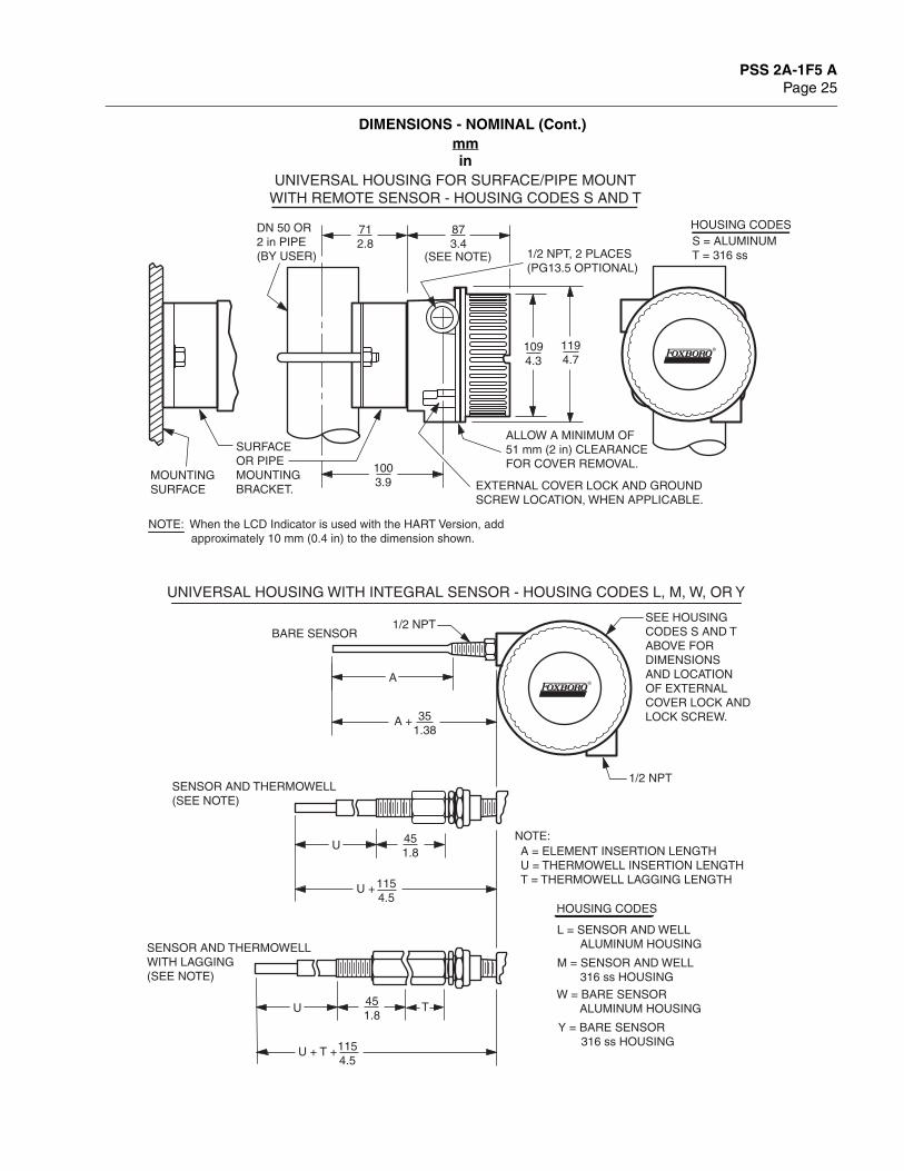
DIMENSIONS - NOMINAL
BASIC TRANSMITTER MODULE - HOUSING CODE B
+
+
+3
20.20.8
441.7
HART UNIT FIELDBUS AND PROFIBUS UNIT
21
36
45
21
36
45
7.60.3
6.00.24
4.60.18
7.90.31
331.3
BASIC TRANSMITTER MODULE MOUNTED TO SURFACE OR DIN RAIL
OPTIONALMOUNTINGCLIP
DIN RAIL SELF-TAPPINGSCREW,PROVIDEDBY FOXBORO
DIN RAIL MOUNT
MOUNTINGSCREWS2 PLACES,PROVIDEDBY USER.SEE FIGUREABOVE FORHOLE ANDCOUNTERBOREDIMENSIONS
SURFACE MOUNT
SURFACE
DIMENSIONS SHOWNARE TYPICAL FORALL ELECTRONICVERSIONS.
NOTE
mmin
PSS 2A-1F5 APage 25
DIMENSIONS - NOMINAL (Cont.)
®
351.38
A
A +
1154.5
U
U +
451.8
1154.5
U
U + T +
T
1/2 NPTBARE SENSOR
SENSOR AND THERMOWELL(SEE NOTE)
SENSOR AND THERMOWELLWITH LAGGING(SEE NOTE)
A = ELEMENT INSERTION LENGTHU = THERMOWELL INSERTION LENGTHT = THERMOWELL LAGGING LENGTH
NOTE:
UNIVERSAL HOUSING WITH INTEGRAL SENSOR - HOUSING CODES L, M, W, OR Y
UNIVERSAL HOUSING FOR SURFACE/PIPE MOUNTWITH REMOTE SENSOR - HOUSING CODES S AND T
®
712.8
1094.3
1194.7
1003.9
1/2 NPT, 2 PLACES(PG13.5 OPTIONAL)
SURFACEOR PIPEMOUNTING BRACKET.
DN 50 OR 2 in PIPE (BY USER)
873.4
ALLOW A MINIMUM OF51 mm (2 in) CLEARANCEFOR COVER REMOVAL.
EXTERNAL COVER LOCK AND GROUND SCREW LOCATION, WHEN APPLICABLE.
MOUNTING SURFACE
SEE HOUSINGCODES S AND TABOVE FORDIMENSIONSAND LOCATIONOF EXTERNALCOVER LOCK ANDLOCK SCREW.
1/2 NPT
HOUSING CODESS = ALUMINUMT = 316 ss
HOUSING CODES
W = BARE SENSOR ALUMINUM HOUSING
L = SENSOR AND WELL ALUMINUM HOUSING
M = SENSOR AND WELL 316 ss HOUSING
Y = BARE SENSOR 316 ss HOUSING
(SEE NOTE)
NOTE: When the LCD Indicator is used with the HART Version, add approximately 10 mm (0.4 in) to the dimension shown.
451.8
mmin

PSS 2A-1F5 APage 26
DIMENSIONS - NOMINAL (Cont.)
351.38
A
A +
1154.5
U
U +
251.0
451.8
1154.5
U
U + T +
T
1/2 NPTBARE SENSOR
SENSOR AND THERMOWELL(SEE NOTE)
SENSOR AND THERMOWELLWITH LAGGING(SEE NOTE)
A = ELEMENT INSERTION LENGTHU = THERMOWELL INSERTION LENGTHT = THERMOWELL LAGGING LENGTH
NOTE:
WEATHERPROOF CONNECTION HEAD WITH INTEGRAL SENSORHOUSING CODES C AND E
1/2 NPT
3.5
893.5
HOUSING CODES
C = BARE SENSOR ALUMINUM HOUSINGE = SENSOR AND WELL ALUMINUM HOUSING
89
COVER CHAIN(REFERENCE)
451.8
mmin

PSS 2A-1F5 APage 27
DIMENSIONS - NOMINAL (Cont.)
351.38
A
A +
1154.5
U
U +
1154.5
U + T +
251.0
451.8
T
1/2 NPTBARE SENSOR
SENSOR AND THERMOWELL(SEE NOTE)
SENSOR AND THERMOWELLWITH LAGGING(SEE NOTE)
A = ELEMENT INSERTION LENGTHU = THERMOWELL INSERTION LENGTHT = THERMOWELL LAGGING LENGTH
NOTE:
EXPLOSIONPROOF CONNECTION HEAD WITH INTEGRAL SENSORHOUSING CODES D AND F
1/2 NPT CONDUITCONNECTION
1124.4
1094.3
HOUSING CODES
D = BARE SENSOR ALUMINUM HOUSINGF = SENSOR AND WELL ALUMINUM HOUSING
WHEN THE LCD INDICATOR ISUSED WITH THE HART VERSION,ADD APPROXIMATELY 12.7 m (0.5 in)TO THE DIMENSION SHOWN.
451.8
U
mmin

PSS 2A-1F5 APage 28
ORDERING INSTRUCTIONS
OTHER M&I PRODUCTS
1. Model Number2. Configured Range3. Tag Number
Invensys Foxboro provides a broad range of measurement and instrument products, including solutions for pressure, flow, analytical, positioners, temperature, controlling and recording. For a listing of these offerings, visit the Invensys Foxboro web site at:
www.foxboro.com/instrumentation
33 Commercial StreetFoxboro, MA 02035-2099United States of Americawww.foxboro.comInside U.S.: 1-866-746-6477Outside U.S.: 1-508-549-2424 or contact your local Foxboro representative.Facsimile: 1-508-549-4999
Invensys, Foxboro, and I/A Series are trademarks of Invensys plc, its subsidiaries, and affiliates.All other brand names may be trademarks of their respective owners.
Copyright 2004-2008 Invensys Systems, Inc.All rights reserved
MB 010 Printed in U.S.A. 0108