n96-14918 - nasa · n96-14918 training ... and connecting communications links is referred to as...
TRANSCRIPT
N96-14918
Training Augmentation Device For The Air Force Satellite Control Network
Captain Keith B. Shoates, USAFAir Force Institute of Technology/Education With Industry
Wright-Patterson AFB, OH 45433-6583
BACKGROUND
From the 1960s and into the early 1980s satellite operations and control were conducted by Air Force SystemsCommand (AFSC), now Air Force Materiel Command (AFMC), out of the Satellite Control Facility at OnizukaAFB, CA. AFSC was responsible for acquiring satellite command and control systems and conducting routinesatellite operations. The daily operations, consisting of satellite health and status contacts and station keepingactivities, were performed for AFSC by a Mission Control Team (MCT) staffed by civilian contractors who wereresponsible for providing their own technically "qualified" personnel as satellite operators. An MCT consists offive positions: mission planner, ground controller, planner analyst, orbit analyst, and ranger controller. Most ofthe training consisted of On-the-Job-Training (OJT) with junior personnel apprenticed to senior personnel untilthey could demonstrate job proficiency. With most of the satellite operators having 15 to 25 years of experience,there was minimal risk to the mission.
In the mid 1980s Air Force Space Command (AFSPACECOM) assumed operational responsibility for a newlyestablished control node at Falcon AFB (FAFB) in CO. The satellites and ground system program offices (SPOs)are organized under AFSC's Space and Missile Systems Center (SMC) to function as a systems engineering andacquisition agency for AFSPACECOM. The collection of the satellite control nodes, ground tracking stations,computer processing equipment, and connecting communications links is referred to as the Air Force SatelliteControl Network (AFSCN).
Unlike AFSC's practice of staffing their MCT with contractors, AFSPACECOM's concept of operations is based onAir Force officers serving as the MCT. Furthermore, AFSPACECOM has started transitioning satellite operationsto Noncommissioned Officers (NCOs). For routine satellite operations, a single Air Force officer will serve asspace operations crew commander and oversee the activities of several NCO satellite controllers. Because of thefrequent turnover of military personnel, retaining trained crews for AFSPACECOM presents some uniquechallenges. Initial training and satellite controller position certification became critical issues to AFSPACECOM.The training pipeline for AFSPACECOM consists of 12 to 18 months of Formal Undergraduate Space Training(UST), 1-3 months Initial Qualification Training (IQT) on the satellite (e.g. Global Positioning System (GPS),Defense Support Program (DSP)) and its command and control system, and 30 to 45 days of control center specifictraining. After completion of training, a satellite operator would have only two years to at best two years and tenmonths left on station. Upon completion of their training the students would be qualified crew members ready toperform their duties in their Satellite Operations Center (formerly known as the Mission Control Complex (MCC)and Test Support Complex (TSC)).
GENESIS OF SATELLITE OPERATIONS CREW TRAINERS
In the early 1980s AFSC initiated development of satellite crew trainers to support Air Force satellite launch andon-orbit operations. Provisions were also made to interface with NASA to support Air Force/NASA shuttlelaunches and missions. Prior to this time, the standard training method for crew training was to conduct trainingexercise on their operational equipment using a "paper simulation" method. Team members were given paperscripts during a training exercise detailing scenarios to which they were to respond (some scripts would providethe operator with failed, telemetry values); the operator's appropriate response(s) would then be evaluated. The"paper simulation" method was laborious to develop and time consuming to conduct for training large groups ofteams coordinating over multiple voice-nets and consoles in support of a launch exercise. Unlike the "papersimulation" method, crew trainers provide Air Force satellite control teams with a simulated satellite telemetry
419
https://ntrs.nasa.gov/search.jsp?R=19960007752 2018-07-17T08:36:40+00:00Z
stream that could be processed and displayed on the crew's command and control system in a dynamic andinteractive manner.
Telemetry Simulation System. The Inertial Upper Stage (IUS) Satellite Operations Center (SOC) at OAFBbecame the first program to benefit from the development of a crew trainer, the Telemetry Simulation System(TSS). The system was developed by the Unisys Corporation (now PARAMAX Systems Corporation), designedusing 8086 technology, and required a significant amount of program unique software development. Althoughinitially fielded in 1984 for the IUS program, several other satellite application models were developed over thesucceeding five years. An upgrade to the TSS hosted on 80286 technology was installed at both AFSCN satellitecontrol nodes, OAFB and FAFB.
The TSS was the first Air Force trainer developed for space operations, which supported integrated trainingbetween the various positions of the SOC crew, the communications segment, and the Resource Control Complex(RCC). The TSS had several shortcomings. Each satellite software model was mission unique with very littlereusable software code between programs. Model development time was from two to three years. Only onesatellite model could be running at a given time on the TSS. The cost for satellite model development wasapproximately $5M to $7M per satellite application, $1.2 M for the hardware platform, and $3M per installationdue to the hardware architecture and Air Force facilities and security requirements. The TSS did not simulate AirForce ground tracking stations; this limitation made the trainer inadequate for two of the five members of thesatellite control crew (an orbit analyst who relied on satellite tracking data and a ground controller who neededtracking station configuration status information). The TSS software was written in PLM and Intel assembler.The code was costly to maintain and was not readily portable to other hardware platforms. Increased trainingand fidelity requirements exceeded TSS hardware architecture capabilities.
Generic Telemetry Simulator (GTSim). As the development on the TSS was reaching its apex in the middle1980s, NASA through a contract with Singer Link (now CAE - Link) began developing the GTSim for the Centaurprogram. Following the Challenger accident, AFSC completed the development of the GTSim to provide thereusable, reconh'gurable training platform to overcome the shortcomings of the TSS. An application for theDefense Satellite Communications Satellite (DSCS) was developed by General Electric under contract with theDSCS SPO and deployed in 1992.
The GTSim again proved the importance of computer simulation to mission success. However, the GTSim didnot live up to expectations. Development cost for the satellite model were approximately $6 M ($1 M over initialprojections because very little of the Centaur software could be reused). Installation cost due to unique GTSimhardware architecture, and Air Force facility and security requirements were in excess of $2.5 M. The softwaredevelopment time increased from one to nearly two years. Like the TSS, there was no ground tracking stationmodel in the GTSim.
THE NEXT GENERATION
Satellite Control Simulation Study. In the latter part of the 1980s the Satellite Control and Data Handling SPO(SMC/CW) sponsored a study (Satellite Control Simulation Systems Study) exploring areas in which simulationand modeling technology could facilitate Air Force satellite control operations. The study concluded that severalof the capabilities required for simulation and operations could share the same software modules if designedproperly. For instance a satellite model and supporting orbit propagation models were needed to supportmission team training, plan validation, and anomaly analysis aids. Software reuse, evolutionary acquisitionprocedures, extensive use of Commercial-Of-The-Shelf (COTS) hardware and software, and a common spacevehicle application user interface were some of the study's recommendations. For satellite crew trainers the majorrecommendations were to maximize reuse of software simulation models, provide a standard trainer architecturefor hosting various satellite models, employ rapid satellite modeling development tools to meet missionobjectives, provide instructional control over telemetry values and training session, and support multiplecontacts. This study set the course for the development of the next generation crew trainer.
420
Training Systems Working Group. A Training Systems Working Group (TSWG) was established within the AirForce Satellite Control community to specify trainer requirements and coordinate activities to promote thedevelopment of a standard Air Force satellite crew trainer. Its membership was drawn from HQ AFSPACECOM,both Air Force satellite control nodes including operators and training personnel, and the Air Force satelliteground system and satellite acquisition agencies. The TSWG supported the conclusions of the Satellite ControlSimulation Systems Study and developed a comprehensive set of operational requirements reflected in anAFSPACECOM Statement of Operational Need (SON 012-88, Aug. 90).
Training Augmentation Device. The opportunity to meet AFSPACECOM's SON arose when the VS. Navy andthe Air Force jointly funded the Training Augmentation Device (TAD) to provide satellite crew training for AirForce SOC crew responsible for operating the Ultra High Frequency Follow-On (UHF F/O) satellite. Therequirements for the TAD were specified in the 50th SpaceWing Technical Requirements Document (Feb. 91), andwere translated into system requirements by SMC/CWD (Aug. 91). These requirements focused on providing acrew trainer that could simulate the UHF F/O satellite, certain satellite anomalies, and Air Force and Navysatellite tracking stations. PARAMAX Systems Corporation was selected to develop the TAD architecture basedon their in-house prototyping efforts. PARAMAX subcontracted to Hughes Aircraft Company, the UHF F/Osatellite contractor, to develop the satellite model for the TAD.
The development strategy for the TAD was based on an evolutionary development concept. While TADrequirements were fully flushed out by the user community in the initial stages, design and development wouldoccur incrementally. A system design covering the overall software and hardware architecture was scheduled toprovide the Air Force community insight into the TAD's architecture. Instead of a single massive softwaredetailed design, a series of small detailed design meetings were held. The above "evolutionary development"approach was initiated to preclude rigidity in specifying a grand design that was likely to be plagued withinnumerable changes when the actual design implementation occurred. Several critical program milestones wereestablished that enabled the contractor to incrementally design and build the TAD architecture. This approachenabled the Air Force community to have significant insight and input into the TAD's architecture throughout itsdevelopment cycle. Installation of TAD hardware at FAFB, completion of TAD's basic common software modelsand delivery of TAD's UHF satellite models were designated as major program milestones. TSWG teaminvolvement was maintained throughout the course of the contract. TSWG members participated in the design ofthe TAD's operator interface and satellite component's building block paradigm. This insured user involvementin the TAD's design throughout its development.
SYSTEM DESIGN OVERVIEW
The primary purpose of the TAD is to provide satellite operations crew readiness training for launch, early-orbit,and on-orbit operations in their SOC. The TAD dynamically simulates the external environment to the SOCincluding the ground tracking stations and the satellite. The TAD permits the SOC crew to verify new satellitecommand(s) or command sequences prior to their transmission to a satellite by comparing the satellite'ssimulated response to the predicted response. The TAD supports off-line analysis of satellite anomalies, workaround procedure, development, and mission planning. TAD satellite subsystem models permit the insertion ofanomalous states permitting the user to match the actual anomalous condition aboard the satellite. Satelliteworkaround procedures can then be developed by SOC crews and verified against the TAD prior to theirtransmission to the satellite.
System Design. The TAD's system design is based on the "open systems" architecture approach. The softwarecan operate in a single environment (e.g., workstation) or take advantage of a symmetrical multiprocessorenvironment This scalability permits the TAD to address simulation applications that support 1 to N simulatedobjects. Symmetrical multiprocessing using portable parallel processing application software was selected tomeet Air Force crew trainer growth and performance requirements. Symmetrical multiprocessing under a UNIXoperating system was selected to meet the TAD's performance requirements. The TAD provides classified (red)and unclassified (black) data separation. Due to limited available floor space within the SOC, the TAD must belocated outside the SOC. The TAD is connected to the SOC via the facilities communication segment.
421

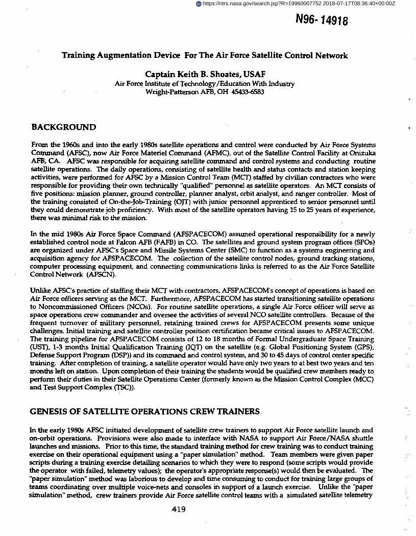
Hardware Design. Except for a Multibus I interface to support unique AFSCN interfaces, all of the TAD'shardware is composed of COTS equipment. The TAD is hosted on two interconnected Unisys U6085minicomputers. One minicomputer runs the ground tracking station network models, while the otherminicomputer runs the satellite models. The hardware is based on an open systems architecture which permitsheterogeneous software, scalability of processors, dynamic processor loading and interoperability. TAD'ssoftware language, operating system, display software file systems, computer interfaces and databases have beenported to other UNIX operating systems (i.e., Sun, HP and IBM). The U6085 is a parallel processor with four dual80486/25 MHz boards capable of 11 Million Instructions Per Second (MIPS). The U6085 provides upwardscalability to a total of fifteen dual boards per U6085. Each U6085 contains over 1 Giga Byte (GB) removable harddrive for storing program unique applications and running in a classified mode.
Network Subsystem/Satellite Subsystem Interfaces
Signal" Network I/OInterface w — Subsystem
KG VaultCommand Transmit/Receive Interface
A
Telemetry StreamOutput Interface
„ NetworkWorkBtation(s)
TbTVpe 1WorksUtistation
Figure 1. UTAD Hardware Design.
Connected to each U6085 minicomputer (satellite and network) is an Operator Interface Station (OIS) consisting ofan IBM RS 6000/520 workstation that provides the human interface. This workstation allows real timemonitoring of selected data points, injecting anomalies, manipulating simulation models, and changingsimulation speed. Each workstation contains over 1 GB removable hard disk which contains any programspecific data, training scripts or classified data. Display of selected satellite telemetry and student interactions is
422
via IBM GT4X 24-bit graphics card. A high speed printer is connected to each RS 6000 to print training data asnecessary. Connectivity between the U6085s, Multibus I and the RS 6000s is via fiber optics or TCP/IP EthernetLAN.
The TAD's Multibus I interface is used to connect to the SOCs AFSCN custom data interfaces. The Multibus I iscomposed of commercially available Single Board Computer (SBC) printed circuit boards. A custom board thatgenerates TAD satellite telemetry attaches through a standard connector to a commercial Multibus SBC printedcircuit board. It supports a variety of telemetry formats and telemetry data rates up to 2.5 Mbps. The telemetrygenerator is the only custom piece of hardware in the TAD's architecture. Data rates are programmable andencoding schemes are selectable. Telemetry commutation is performed on the host programmable SBC board. ALoral NASA Command Formatter (NCF) board resides on the Multibus I and serves as the command ternaryreceive port for SOC satellite commands into the TAD. Six different telemetry boards can be connected to theMultibus I, which could be driven by six separate simulations at the same time, thus supporting six different SOCtraining crews.
Software Design. The software design was predicated on the use of the Ada programming language andwhenever feasible the use of COTS software to reduce development cost. Use of Ada programming language asthe main software language was mandatory per DOD policy and Air Force policy. Use of other languages in theTAD are limited to special functions or routines such as existing I/O driver software, revised satellite models,
. interfaces to UNIX or COTS software, and fourth generation language (4GL) with Structured Query Language(SQL) database code. Two different operating systems support the TAD: U6085 Unisys System V OperatingSystem, and the IBM RS 6000 AIX Operating System. Both systems support a security rating of C2 and providediscretionary access control, user identification, passwords, and audit trails. The TAD workstation employsX-Windows X.11 standard to establish its windowing environment. The user can open several display windowson his work station and monitor the status of several on-going activities. X-Windows standardize the manner inwhich a user can open or dose display windows permitting increased operator productivity. The workstation'shuman interface is developed using the Dataviews tool from Visual Intelligence, Inc. Dataviews supports X-Windows.
Database development is supported by the Progress tool from Progress, Inc. The 4GL that is provided byProgress inherently supports concurrency control, recovery, import/export of data. The Progress 4GLStructured Query Language (SQL) standard is also used to build user data displays and report requests.
TAD local area network uses a standard IEEE 802.3 Ethernet protocol supporting the Network File System (NFS)and Remote Procedure Call (RFC) open standards sponsored by Sun Microsystems, Inc.
On-line documentation access to the TAD's user manual and another documentation is supported by the desk toppublishing tool Framemaker, which uses quick look-up hypertext links provided by Frame Technology Inc.
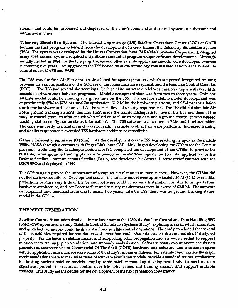
Telemetry commutation software using PLM software developed for the TSS was adapted into the TADarchitecture along with the NASA Command Formatter software. Figure 2 identifies the various commerciallanguages by percentage of total lines of code (573.5 KSLOCs) used in the TAD.
423
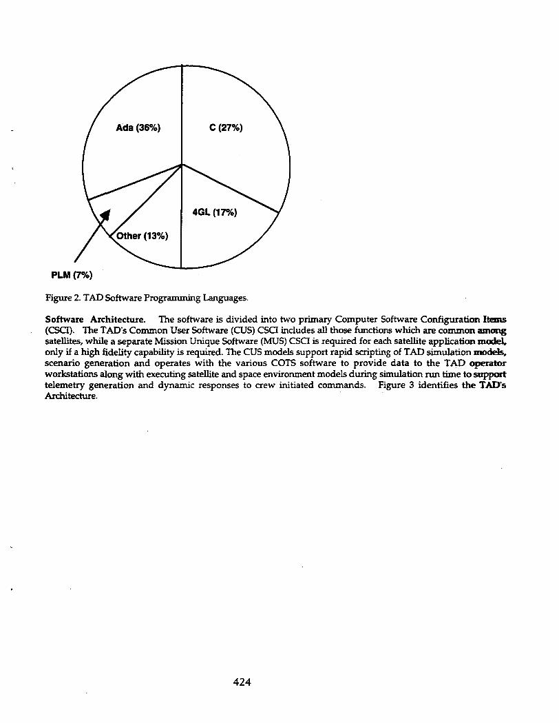
PLM (7%)
Figure 2. TAD Software Programming Languages.
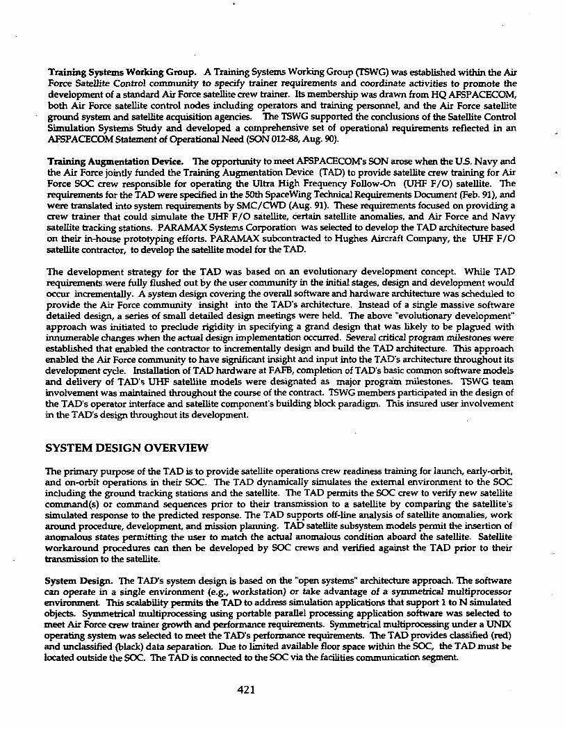
Software Architecture. The software is divided into two primary Computer Software Configuration Items(CSCI). The TAD's Common User Software (CUS) CSCI includes all those functions which are common amongsatellites, while a separate Mission Unique Software (MUS) CSCI is required for each satellite application model,only if a high fidelity capability is required. The CUS models support rapid scripting of TAD simulation models,scenario generation and operates with the various COTS software to provide data to the TAD operatorworkstations along with executing satellite and space environment models during simulation run time to supporttelemetry generation and dynamic responses to crew initiated commands. Figure 3 identifies the TAD'sArchitecture.
424

Lines of Code
Actual: 573.5 KSLOC
TAD Platform
uus
UHFF/O
(100)
MUS
GPSIIA
MUS
Milstar
(TBD)
CUS - MUS Interface(7.5)
Common User Software (CUS)Common Models f159)Telemetry SensorsElectrical Orbital DynamicsCommand AttitudePropulsion Thermal
Systemsl/FSvsComp EnvOPSI/FData Bases
(446.5)
Operating System(s)AIX & Unix System V.3 With BSD File System
Common User Equipment (CUE)Processing Human Interface Site Specific(2) U6085S (2) RS 6000s Connectivity
Input/Output(2) Tlm/Cmd
Figure 3. TAD Architecture.
Common User Software. The TAD CUS employs Ada tasking model constraints which permit the spawning ofmultiple Ada tasks, each representing a simulation unit (e.g., satellite and tracking stations). When a parallelprocessor environment is present with a parallel Ada run time system, the simulation units takes advantage of theadditional processors. The TAD's common user software (CUS) consists of a collection of reusable or common -models such as satellite commanding, orbit line of sight telemetry, orbit dynamics, satellite attitude, satellitesensors, actuators, orbit line-of-sight, propulsion electrical power, telemetry, tracking and control, andConnectivity models. Figure 4 identifies the TAD's Computer Software Components. A control system basedblock programming paradigm is also provided which permits training personnel to rapidly develop mediumcomplexity satellite simulations.
425

DatabaseCSC
Operator I/FCSC
System Sv»CSC
Env. SimulationCSC
Simulation EnqCSC
CommunicationCSC
Data RoutingCSC
Ucer AlgorithmCSC
Satellite Sim.CSC
TJc Station Sim.CSC
Figure 4. TAD Computer Software Components (CSCs).
The TAD CUS provides the software environment in which all TAD simulation activities take place. A broadsuite of simulation tools is provided by the CUS such as scripting, logging, script generation from logs, SOCinterface, simulation control, fast/slow forward time control, common satellite and sub component models,simulation state save/restart, multiple simulated time/spatial universes, multiple simulated objects, andevaluation utilities and reports. In addition to these features, the TAD CUS provides reconfigurable commonmath/logic models whose behavior is defined through database parameters. The CUS also provides a blockprogramming capability that supports modeling of subsystems which have a high degree of variability thatcannot effectively be handled by the common models.
Database. The TAD database CSC provides the means by which an operator can enter new data, change existingdata, or delete data from the MUS database. The MUS database is the data source for tailoring the behavior of thesimulation environment and the objects which are within the environment. These functions are accomplished byDatabase application code, database load, and the Progress Database development tool modules.
The Database module provides database management, environment definition, satellite definition, trackingstation definition, and software discrepancy report/definition. The database manager provides templates fromwhich the operator may create new databases which are automatically cataloged. These templates may be createdfor a family of satellites which are similar which are then tailored for specific mission requirements. The softwarediscrepancy report/definition function provides on-line identification of hardware or software problems.
The Database Load module provides a means of uploading actual SOC databases used in the operationalcommand and control system directly into the TAD databases.
The Progress Database development tool, a COTS 4GL client/server product, is used to develop and maintainTAD CUS database application code.
Operator Interface. The operator interface CSC handles all of the processing required to present information toand receive directions from the trainer during execution of a training session. These functions are accomplishedby the Human Interface, Display Processing, Scripting, and Data Views Tool modules.
426

The Human Interface module creates a main operations control window which is used by the trainer to initiate atraining session. Each Operator Instructor Station (OIS) hosts exactly one Human Interface process whichmaintains separate control for each environment and simulated unit that is controlled by that OIS. The HumanInterface takes advantage of a graphical user interface features such as windowing, mouse-and-menu control,and color graphics.
The Display Processing module is used by the Human Interface module to provide processing of 2-D graphicsdisplays. The Scripting module processes any scripts that have been defined for the training session. TheData Views Tool module supports the custom development and maintenance of 2-D graphics displays.
Simulation Engine. The simulation Engine CSC provides the run-time control functions on the compute engine(i.e., U6085 minicomputer) which are accomplished by Simulation Engine Control and Ada Task Controlmodules. The Simulation Engine Control module initiates the processes that execute on the minicomputer,establishes communication with the OIS, and starts the processes that provide communication with the APSCNinterface software components.
The Ada Task Control module provides control over several module such as the Environment Simulation, theSatellite Simulation, and the Tracking Station. It is started by the Simulation Engine Control module when asimulated space/time environment is requested.
Communications. The communications CSC provides the communications interface services between all thehardware and software components, regardless of whether they are on the U6085 minicomputer or the RS 6000workstation. These functions are accomplished by Ada Communications, Multibus I Communications, andIntersubsystem Communications modules.
The Ada Communications module provides communications between Ada tasks running on the U6085 and UNIXprocesses residing on the RS 6000. The Multibus I Communications module provides communication betweenthe TAD system and the Air Force communications switch interface to the SOC. The IntersubsystemCommunications module provides communication between the U6085 satellite and network subsystems.
System Services. The system services CSC provides communications, data routing and software utility supportfor TAD software components. These components include system control processes, human interface and displayhandling processes, Multibus I input/output processes, user defined algorithms, space/time environmentmodels, and satellite and network subsystem models. These functions are accomplished by Time Control,Physical Environment, and Environment Communications modules. The Time Control module provides the OIScontrol over the TAD's run time environment, such as fast/slow forward, freeze, state save, start/stop. ThePhysical Environment module provides control of the simulation of the necessary physical characteristics of spacesurrounding the earth (e.g., sun, moon and planets). The Environment Communication module provides controlover communication between objects in the same or different space/time environments.
Environment Simulation. The environment simulation CSC provides the simulation of space/time environmentin which the satellite and ground tracking stations operate. The simulation of an environment includes:modeling of the passage of time from a specified starting point and the modeling of the necessary physicalcharacteristics of space surrounding the earth.
Data Routing. The data routing CSC provides the transparent exchange of data between TAD components. Eachsimulated unit possess a data pool which has been generated by the Simulation module (Environment, Satellite,or Tracking Station) for that unit. Data in an objects data pool can be accessed by any of the TAD's components.It is this loosely coupled nature of the system that provides the flexibility to turn on/turn off individual modelsand update values in a data pool from alternate means (databases, look-up tables, external sources).
User-Defined Algorithm (UDA). The user-defined algorithm CSC provides the mechanism for the trainer tomanipulate data during the execution of a training session. UDAs may be used to generate telemetrymeasurands, manipulate data for display purposes, or generate specific simulation data. UDAs may interact withother algorithms and TAD models via the data pools.
427
Satellite Simulation. The satellite simulation CSC provides satellite simulations capable of receiving space vehiclecommands from a SOC and producing dynamic telemetry output which reflects ongoing evolution of thesimulation environment and the simulated satellite's response to the received commands. The simulation of asatellite includes the modeling of the health and status of various subsystems. Satellite modeling employscommon math/logic models that obtain satellite-specific characteristics from parameters specified in databases.The TAD common satellite subsystem models include: Orbital Dynamics, Attitude, Sensors, Actuators,Propulsion, Electrical Power Subsystem, Commanding, Telemetry Processing, Eclipse, Telemetry andCommanding Control and Status (TCCS), and a Common Spacecraft Processor Model. These modelscommunicate primarily through Data Routing.
Tracking Station Simulation. The tracking station simulation CSC provides for the simulation of both Air Forceand Navy satellite tracking stations. These simulations respond to configuration and control directives from theSOC and return realistic tracking and status information. This module also provides modeling of core equipmentand antenna subsystems of the tracking stations. Like the satellite simulation module, this module employscommon math/logic models that define tracking station-specific characteristics from parameters (tracking stationcoordinates such as longitude, latitude, altitude and obscura data) specified in databases. The TAD commontracking station models include: Tracking and Antenna, Command Generation, Tracking Station Control andStatus (TSCS), and Tracking Station Equipment.
Mission Unique Software. The TAD's Mission Unique Software (MUS) constitutes the specific satelliteapplication model (e.g., GPS or UHF F/O). For instance GPS Block IIA software running on the TSS at FAFBand totaling 45 KSLOCs of FORTRAN 77 is being transcribed into Ada for use on the TAD. It is scheduled to becompleted by the Spring of 1994. The total estimate Ada lines is 17.5 KSLOCs. The reason for the significantreduction in lines of code is partially due to the nature of Ada being a high order language, but mainly due to theability of TAD's common models to supplant significant portions of the original FORTRAN code. In the case ofthe UHF F/O satellite model developed by Hughes Aircraft Company, a custom C code to Ada softwareinterface was developed. This interface permits the Hughes model (previously developed) to run in the TAD'ssoftware environment. The Hughes UHF F/O MUS model consists 100 KSLOCs of C code and is a modificationof a previously developed satellite simulation for the Hughes HS601 satellite family.
PROGRAM STATUS
The TAD development is currently completing development. The TAD hardware and an initial softwarecapability was installed in the summer of 1992 at FAFB. A successful demonstration of generating a telemetrywavetrain and of receiving SOC commands was completed in February 1993. The Hughes UHF F/O satellitemodel was ported over to the TAD and successfully run with the CUS in a simulation mode at PARAMAX'sdevelopment facility in March 1993. The installation of the basic TAD CUS and UHF F/O MUS is scheduled forthe/ summer of 1993 with an enhanced version of the CUS with the block programming capability scheduled fordelivery in early 1994.
Installation of a TAD at OAFB is underway with completion scheduled for the end of 1993. The GPS Block HAsoftware rewrite has started and is expected to be completed by the spring of 1994. The MILSTAR satellite SPO isin the planning stages of developing a MILSTAR MUS to support training in their SOC at FAFB. The GPS JointProgram Office (JPO) is considering acquiring a TAD to support training at its satellite Master Control Station atFAFB along with developing an MUS for its new GPS Block IIR satellite.
An additional use of the TAD is as a test driver in the AFSCN Data Systems test program. A developmentlaboratory TAD has been installed at IBM's satellite ground control software maintenance facility to supportsoftware maintenance and test activities. It is expected to be operational by the summer of 1993.
428
FUTURE DIRECTIONS
An advantage of the TAD is its portability across hardware platforms. Current technological advances make itfeasible to port TAD software onto high performance graphic workstations (parallel architecture) and place theminto the SOC at a significant cost savings over the present hardware architecture. This alternative is beinginvestigated. With the TAD being ported to a workstation and located inside the SOC, its facility installation andsecurity cost could be significantly reduced.
The TAD has been adopted as the standard AFSPACECOM crew trainer. Additionally, it has been identified asthe simulation element for the Air Force's next generation satellite command and control architecture, theAdvanced Satellite Control (ASC). The ASC stipulates a distributed architecture with heavy reliance on openarchitecture and commercial standards interconnected via high capacity high speed fiber optic data links.
Bibliography
1. The Aerospace Corporation, TOR-0089(4485-01)-1, Satellite Control Simulation System (SCSS) Summary,February 1990.
2. AFSPACECOM Statement of Operational Need 012-88, Satellite Control Simulation System (SCSS), August1990.
3. AFSPACECOM UHF Follow-On Training Augmentation Device Technical Requirements Document, 8February 1991.
4. System Specification for the Ultra High Frequency Follow-On Training Augmentation Device (UTAD),UNISYS, SS-CUE-000349, 2 August 1991.
5. Software Requirements Specification for the Common User Software for the Training Augmentation Device(TAD), CG-000360,20 January 1992.
6. Prime Item Development Specification for the Training Augmentation Device (TAD), CP-CUE-000358, DRAFT,30 September 1991.
429