n87-27243 - nasa · n87-27243 application of ... particular importance to the united states navy is...
TRANSCRIPT

N87-27243
Application of NASTRAN/COSMICin the
Analysis of Ship Structures to Underwater Explosion Shock
D.J. Fallon, F.A. Costanzo, R.T. Handleton
G.C. Camp and D.C. Smith
David Taylor Naval Research and Development Center
SUMMARY
This paper presents the application of NASTRAN/COSMIC in
predicting the transient motion of ship structures to underwater
non-contact explosions. Examples illustrate the finite element
models, mathematical formulations of loading functions and, where
available, comparisons between analytical and experimental results.
One example shows the use of NASTRAN/COSMIC coupled with a
structure/water interaction theory to predict early time dynamic
response of the USS YORKTOWN during shock trials in 1984. Another
example is the analysis of a MK-45 gun conducted in support of the
Ship Systems Engineering Standards (SSES) program. Use of the
substructuring feature of NASTRAN/COSMIC in the analysis of the
Vertical Launch Missile System is illustrated for the recently
constructed USS MOBILE BAY. Another example illustrates the
analyses of two mast structures on the USS KAUFMANN. Finally, an
example of the analysis of a SWATH structure is presented.
INTRODUCTION
The evaluation of dynamic responses of surface ships and
submarines to a shock environment is a very important problem in
naval research. The fundamental characteristic of the shock
experienced aboard naval vessels is the sudden increase in the
velocity of the structural member. Equipment supported by these
structural members may be adversely affected by this sudden
increase in motion. There are two basic types of damage to
equipment which concerns the naval designer: mechanical damage and
mal-operation.
Surface ship shock loading may result from three sources:
l.underwater non-contact explosions, 2. contact explosions and 3.
air blast from aerial bombs or from the vessel's own armament. Of
particular importance to the United States Navy is the response of
ship structure to underwater non-contact explosions. The Underwater
Explosions Research Division (UERD) of the David Taylor Naval
Research and Development Center (DTNSRDC) uses both analytical and
experimental techniques in research efforts aimed at finding
solutions to this complex problem. One of the primary analytical
tools used at UERD is NASTRAN/COSMIC.
ANALYSIS OF USS YORKTOWN
The USS YORKTOWN (CG-48) is the second ship constructed in the
184
https://ntrs.nasa.gov/search.jsp?R=19870017810 2018-05-29T23:46:47+00:00Z

USSTICONDEROGACLASSof guided-missile cruisers. The USSYORKTOWNhas an approximate displacement of 9,1OO tons. This ship is arevised version of the USSSPRUANCEclass destroyer using the samehull and propulsion system but incorporating the AEGIS weaponsystem(l). The USSYORKTOWNwas shocked tested in September of1984. The purpose of this section is to illustrate the use ofNASTRAN/COSMICcoupled with a structure�water interaction theory topredict the early time vertical response of the entire ship duringthese trials.
The simplest representation of the structure/water interactionis with an impulse equal to the momentumof the displaced water inthe free field. This impulse is applied from below to a beam modelof the ship. At the termination of the impulse load atmospheric and
gravitational forces are applied to the model from above (Refer to
Figure i). This approach is reasonable because the ship displaces
it's mass in the water and buoyant forces are lost due to
cavitation around the ship during the impulse loading phase of the
ship motion. This approach emphasizes the structural response while
de-emphasing the complex fluid-structure interaction; thereby,
considerably simplifying the analytical calculations of the dynamic
response.
Previous UERD research efforts have shown that the total
momentum of a structural node on a surface ship can be approximated
by the use of the "spar buoy" model. The fundamental assumption of
the "spar buoy" model is that a given structural node is "kicked
off" with the same average velocity as a column of water with the
same depth as the draft of the ship at the corresponding location
in the free field. The derivations of the equation to compute thetotal momentum can be found in Reference 2.
A finite element model consisting of forty flexural beam
elements was utilized to evaluate the dynamic response of the ship.
The element's sectional properties (i.e., moment of inertia and
cross sectional area) and mass distribution were obtained from
design calculations performed by the Naval Sea Systems Command
(NAVSEA). Previous analytical and experimental work (3) has
demonstrated that the higher frequencies of vibration are
significantly effected by the exclusion of shear deformation. Shock
loadings tend to excite the higher modes of vibration; therefore,
to ensure more accurate results the contribution due to shear
energy via an effective shear area was included in the analysis.
Due to the spherical nature of the shockwave, proper consideration
was given the the arrival of the shockwave at each structural node.
Gravity and atmospheric pressure were accounted for by use of a
loading function applied at the time of cut-off of the impulse
load. The analysis was performed on a CDC 176 mainframe.
Figure 2 illustrates a comparison of the normalized
experimental and analytical results for a location on the ship's
keel near the stern. This figure illustrates excellent correlation
between the experimental and analytical curves with respect to
shape and peak value for the first thirty milliseconds. A similar
comparison is illustrated in Figure 3 for the velocity at the
185

amidships location. Finally, a comparison of the velocity at alocation near the bow of the ship is depicted in Figure 4 . As inthe case of the other two location, excellent correlation was
obtained for the first thirty milliseconds.
ANALYSIS OF A MK 45 GUN MODEL
Modular weapons installation is a very important concept to
naval ship and weapons designers. The modular weapons design
concept offers the United States Navy several advantages over the
classical methodology of designing ships. The first major advantage
is the flexibility of upgrading weapons as the technology of weapon
design changes in the future. Another important advantage is the
ability to interchange weapons systems in the fleet. This allows
the Navy to essentially change the mission of any given ship as may
be required by the ever changing world situation.
DTNSRDC/UERD was tasked to participate in the analysis and
development of design standards for modular weapons via the Ship
Systems Engineering Standards (SSES) program. The first part of
this task was to perform a detailed analysis of the MK 45-54
caliber 5 inch gun module. To accomplish this task a NASTRAN/COSMIC
finite element model (see Figure 5) was prepared for the forward
ship zone between structural bulkheads of the DDG-51 at the
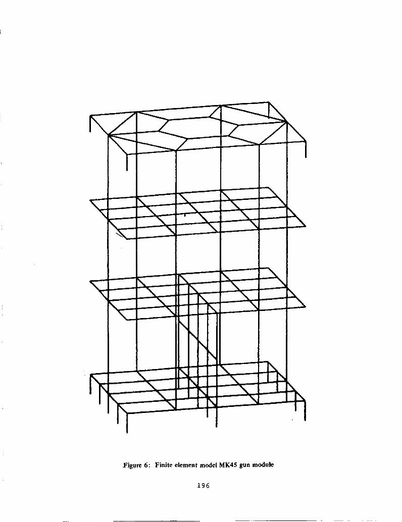
location of the gun module. A NASTRAN/MSC model (see Figure 6) of
the gun module developed by FMC/NOD was converted to a
NASTRAN/COSMIC model and then interfaced with the ship model. The
combined model was accelerated at the hull with a prescribed motion
history to simulate the expected motions of the ship during a full
scale shock test in the vertical and athwartship directions.
The basic assumption in the computation of the transient
motion of the MK 45 gun module is that the hull of any section of
the ship between transverse bulkheads moves as a rigid body in the
vertical and athwartship directions. To compute this rigid body
motion in the vertical direction, the method outlined in the
previous section was utilized. Specifically, a NASTRAN/COSMIC beam
finite element representation of the entire ship was analyzed in
the time domain. The ship loading was via the "spar buoy"
assumption. The output from this analysis was then used as input
for the analysis of the gun module.
The translational motion in the athwartship direction is an
adaptation of a technique for computing submarine rigid body
motion. Figure 7 illustrates the structural model used to compute
the rigid body motion of the hull in the athwartship direction.
This model assumes the hull is i) a rigid body, 2) the loading
function is an exponential decaying function calculated by the
explosive charge similitude equation, 3) the loads are applied to
the structural nodes on the shot side of the hull and 4) the
resistance of the water on the side away from the shot is
proportional to the velocity (i.e., viscous damping). Writing the
equations of motion and numerically integrating through the time
domain yields a prescribed displacement for the motion of the hull.
Figure 8 illustrates a normalized comparison of the analytical and
186

experimental values for a typical cross section of the USSYORKTOWN.As illustrated, the early time history of the ship ispredicted quite accurately.
The finite element model of the ship structure consisted of
CQUADI, CTRIAI and CBAR elements. Orthotropic plate theory was
assumed in modeling the plate and stiffener combination of the ship
bulkheads. A coarse finite element mesh was assumed since interest
was in the computation of displacements and not stresses in the
ship structure. The computation of the response of structures due
to impulsive loadings, the computations were performed on the
coupled equations of motion through the time domain. To achieve the
prescribed acceleration at the boundary nodes, a force of a
magnitude equal to the acceleration times i0 was applied at the
boundary node having a mass of i0 .
ANALYSIS OF THE VERTICAL LAUNCH SYSTEM
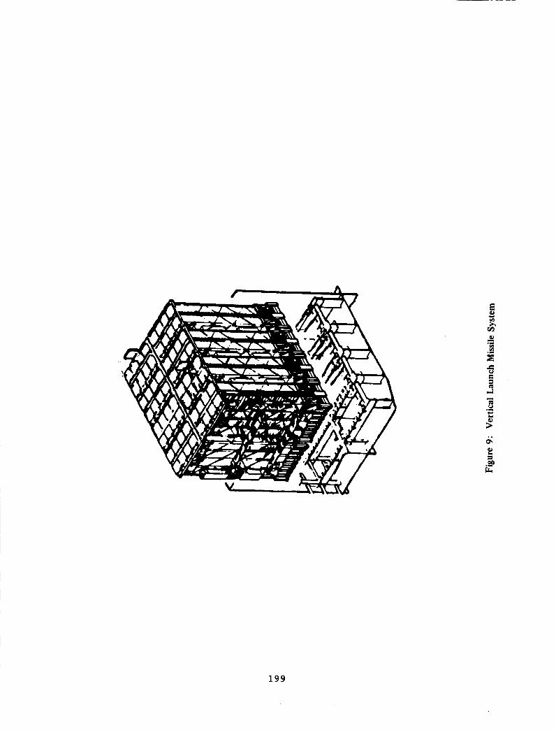
The MK41 Vertical Launch System (VLS) as shown in Figure 9 is
an important addition to the United States Navy weapons arsenal.
The MK41 system provides offensive and defensive capabilities in a
single launcher and was designed as an alternative to single and
dual-rail launching systems. The weapon system meets the Navy's
needs for reliability, increased firepower, flexibility and reduced
manning at manageable costs.
DTNSRDC/UERD was tasked by NAVSEA to participate in the
predicting the shock response of the VLS in the recently
constructed USS MOBILE BAY (CG-53) during full scale ship shock
trials scheduled for the later part of May 1987. The specific
objective of the UERD task was to predict the transient response
between the VLS foundation and the USS MOBILE BAY ship structure.
To accomplish this goal, NASTRAN/COSMIC finite element models were
prepared for sections of the ship structure at the forward and aft
launcher locations. A reduced mathematical representation
(stiffness and mass matrices) of the VLS generated by the prime
contractor, Martin Marietta, using NASTRAN/MSC on an IBM 370
computer was substructured into the ship structure models. The
combined model was accelerated at the hull with a prescribed
acceleration to simulate the expected motion of the ship during a
full scale shock test in the vertical and athwartship directions in
exactly the same technique described earlier for the MK-45 gun
module. The results of these analyses were provided to Martin
Marietta for use in detailed stress calculations through the timedomain.
Figure I0 and Figure Ii illustrate the completed finite
element models for the forward and aft launcher locations,
respectively. In developing these models, substructuring
capabilities of NASTRAN/COSMIC were extensively utilized to
expedite model generation and to aid in combining the mathematical
models of the VLS to the ship structure model. Figure 12
illustrates the use of the substructuring commands to generate the
completed model of the forward launcher location. First a finite
element model of one half of the ship structure as illustrated in
187

Figure 12a was created as a basic structure in a Phase One run. Thecenterline bulkhead structure illustrated in Figure 12b was alsocreated as a basic structure. In addition, the mathematicalrepresentation of the VLS structure as illustrated in Figure 12cwas used to define a basic structure via use of the INPUTT2 DMAP
module. Finally, a Phase Two run was completed which created a
symmetrical image of the basic structure in Figure 12a (illustrated
in Figure 12d) and combined all the basic structure at interfacing
grid points to form the complete ship structure. An additional
Phase Two transient (Rigid Format 9) run was performed on the
complete structure to obtain the motion at the foundation interface
between the VLS and the ship structure. The results of this
analysis was recovered via a Phase Three run and provided to Martin
Marietta for the analysis of their superelement representation of
the VLS through the time domain.
As previously mentioned, the USS MOBILE BAY will be shock
tested in May 1987. The results of this analysis will be used to
make comparisons with the experimental data obtained. The VLS will
be heavily monitored during the test; hence, there will be an
excellent data base to compare experimental and predicted results.
ANALYSIS OF MAST STRUCTURES ON USS KAUFMANN (FFG-59)
The dynamic response of mast structures under shock loading is
of great concern to the ship shock community. Although the
structural model of a mast type structure is rather simple, the
complexity in the analysis comes from the assumed boundary
conditions and the loading in terms of motion histories at these
boundaries. DTNSRDC/UERD has been tasked by NAVSEA in support of
the future shock trials of the USS KAUFMANN to develop a
methodology to estimate the dynamic response of the masts and
equipment supported by the masts.
The USS KAUFMANN supports two primary masts: Foremast/SPS-49
Support Tower and the Main Mast. The primary function of the
foremast is to carry the SPS-49 Air Search Radar. This radar is an
important element in the ship's C3I (Command, Control,
Communications and Intelligence) capabilities. The main mast
supports the great majority of the remainder of the ship's C3I
equipment. This equipment aids the ship in communications,
navigation and readiness for combat.
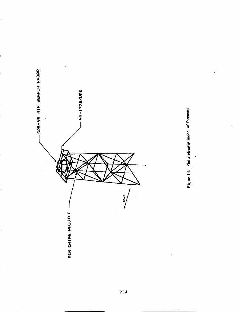
Figure 13 and Figure 14 illustrate the finite element models
of the main mast and the foremast, respectively. The structural
tubing and platform stiffeners were modeled using CBAR elements.
Platforms on both masts were modeled using CQUAD2 and CTRIA2 plate
elements. Equipment was modeled as concentrated masses via the
CONM2 bulk data card.
As previously mentioned the complexity of the analysis of mast
structures lies in the evaluation of the kinematic description of
the boundary conditions. At the writing of this paper, studies are
being conducted to develop a technique to determine the most valid
set of boundary conditions to employ. The use of the "spar buoy"
188

model and the athwartship model discussed in preceding sections
appears promising. Studies are being made to determine amathematical model which accounts for the attenuation of the keel
response (which the "spar buoy" model approximates) through the
ship structure to the base of the mast structure at the weather
deck level.
ANALYSIS OF SWATH STRUCTURE
The Small Waterplane Area Twin-Hulled (SWATH) ship is a unique
United States Navy hull form. Figure 15 presents a cross sectional
view of a SWATH ship finite element model. This half bay, half
cross section finite element model was generated by the Ship
Structures Division of DTNSRDC. The model was designed to analyze
stresses generated in the haunched region by a psuedo-static wave
loading on the strut. DTNSRDC/UERD was tasked to analyze the SWATH
hull form to a shock loading from an underwater explosion.
The finite element model, provided by the Ship Structures
Division, consists of membrane, plate, rod, and bar elements. The
model employs 1500+ elements and i0000+ degrees of freedom. To
conduct a dynamic analysis, several modifications were made to the
model. The primary change involved increasing the mass of the
model to equal the displaced mass of a comparable section of the
ship under construction. The Nodal Weight Generator of
NASTRAN/COSMIC reduced the effort of this modification.
A force-time history impulsive type loading was applied at the
strut end cap to simulate the underwater shock loading. This type
of loading was simple to calculate and to apply to the structure.
An impulsive type loading could be applied to this structure
because of the area of concern is the haunched region. Excessive
stresses in the strut due to localization of the loading were
ignored.
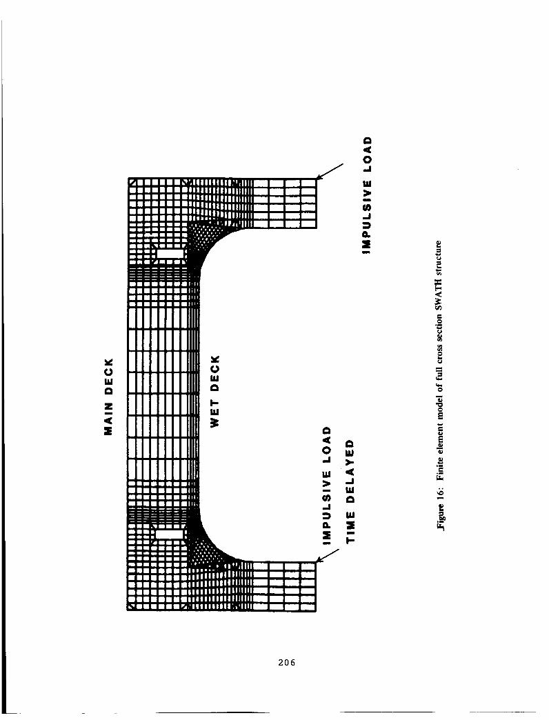
The shock loading from an underwater explosion to the SWATH
hull form loads both Struts and submerged hulls. The shock loading
is not symmetrical (Figure 16). The near hull loading differs from
the far hull loading in magnitude, direction, and phasing. To
account for the unsymmetrical loading it was necessary to utilize a
full cross section model of the SWATH. Due to the detail of the
model and time requirements, substructuring was chosen to create an
equivalent structure and combine the two substructures into one
composite structure. Substructuring allowed for varying the
magnitude and the direction of loadings to each substructure.
Utilizing the DELAYS card, the phasing delay of the shock loading
was easily implemented.
CONCLUDING REMARKS
This paper has presented the analyses using NASTRAN/COSMIC of
several different types of naval structures subjected to a
non-contact underwater explosive loading that the Underwater
Explosions Research Division has conducted. Predicting the response
of ships to withstand underwater shock loads is as much (if not
189

more) an art as it is a science. Hence the development of reliableanalytical techniques to evaluate the response of ships to thistype of shock loading provides a very fertile area for research.Using experimental and analytical methods, DTNSRDC/UERDiscommitted to assisting the Naval community in achieving this goal.
The NASTRAN/COSMIC is an important tool in this task.
REFERENCES
i. Polmar, Norman, The Ships and Aircraft of the U. S. Fleet, Naval
Institute Press, Annaplois, Md, Copyright, 1981.
2. Fallon, Dennis J.,"The Dynamic Response of Naval Structures to
the Application of a Loading Function to Predict Underwater
Explosions," Old Dominion University Research Report, March, 1985.
3. Mathewson, Alice W., "Calculation of the Normal Vertical
Flexural Modes of Vibration by the Digital Process," TMB Report
706, February, 1950.
190

-I-
(+
I
!
I
.-- C
m
it
Z
J
x
w
w
(X:o
,-,_.
--I--
P
m
It
191

I
|
U
XZ
W__._X<WZ
mT"t
i
-°°
.o° ° o°
I J ! t m
| | _ m |ol eS d aS oS
AI IrOO'_JA 03Z TqVld_lON
]I-,,
O
O
r,_
r,_
0
E
>.
192

IBqe.4
m
'qv4
|..X
Q
0
0z !S
eo
• /
m
mN
l
: • - ..... __:-............ Q
d d d d d
o
m
_J.I_X)'13^ O_ZI'IVH_IOI_i
193

B.4
(.3
UJ "_Z
m
• wo° *
""".._..
u1
°_
°.°°°" _
o°
: /°,Oo
14 ,4 d d
_.1.130"13A 133Z r'IVHMON
0[...
0
r,_r_
o
_r0
2>.
194

Figure 5: Finite element model DDG - 51 gun location
195
/
l_igure 6: Finite element model MK45 gun module
196

Iw OIimW u IDI DDIWTID ILDLP. LD. _
glgus, lli-Wl.- oi.- o,l.Pull s"ll ulli_ i.il i.p Gli_ _m. HI" fqlR
,.-,.. sP.. z
• ,., s w __l P'l
M N M u
I,_ I_. 1,_E
t
..=.
q,t=
F,:t_==..=
t
UD
8U
AE
UqD
LA
197

|
#_..# °..'"
W_ -"
X_Im_.q_ °, . .O,o'°" " " '.'o° ° ° "o"
:1 "_ °°o..O.
oO°.°°o-
og-°
°''°OO°o°.
.8
,8 !
M
i,-
"::"'_em
d d d d d
A..I.Z_O"I3A 03Z_
0
0
r_r,_
e_
E
r_
E
X
IgB
E
r_
=j
m
°_
>
199

,.=
p=
E
E
200

m
E
o_
..=
o.
201

oi
M
/
m
C
.r._=
.=
m
_E
202

cz _.M q,4
(nm,4"
w.J
E
a
o
-g
E
°_
1-q
204

205
Wa
Zm
<I
a<o.i
w
u
W.I
Ckxm
U
=:<
o
2
o
N
206