n2 integration with the nae technical bulletincgproducts.johnsoncontrols.com/met_pdf/1201683.pdf ·...
TRANSCRIPT
N2 Integration with the NAE Technical BulletinCode No. LIT-1201683
Issued February 4, 2019Refer to the QuickLIT website for the most up-to-date version of this document.
Document Introduction.............................................................................................................2Switchable Communications Protocols...........................................................................................2
Related Documentation.............................................................................................................3N2 Integration with the NAE Overview.....................................................................................3N2 Device Point Mapping Tables Overview.............................................................................4Supported Application Specific Controllers (ASCs)..............................................................4Detailed Procedures..................................................................................................................5
Adding N2 Integrations.......................................................................................................................5Adding N2 Field Devices Manually (Online or Offline)....................................................................7Adding N2 Field Devices Online Using Auto Discovery...............................................................11Adding Extensions to an Object......................................................................................................13Adding a Resource File Extension......................................................................................................16Adding a Trend Extension...................................................................................................................17Adding a Totalization Extension..........................................................................................................18Adding an Alarm Extension.................................................................................................................19Adding an Averaging Extension..........................................................................................................20Deleting Extensions from an Object...............................................................................................21Copying Extensions to a Field Device or Field Point (Offline Only)............................................22Adding N2 Field Points to an Archive Database............................................................................23Adding Field Points Using Assisted Mode Definition...................................................................25Adding Field Points Using Manual Mode Definition......................................................................28
N2 FEC, FAC, and VMA Point Limits......................................................................................33N2 Device Point Mapping Tables............................................................................................34
AHU....................................................................................................................................................34Unitary (UNT).....................................................................................................................................35VAV Controller...................................................................................................................................35VMA 1400 Series...............................................................................................................................35Phoenix Fume Hood (PHX)..............................................................................................................36Metasys Integrator Unit....................................................................................................................36Vendor Device (VND)........................................................................................................................37ILC......................................................................................................................................................37Intelligent Fire Controller (IFC)........................................................................................................37TC-9100 Terminal Unit Controller....................................................................................................38Lab and Central Plant Controller/Digital Controller (LCP/DC9100)..............................................41DX-9100 Extended Digital Controller..............................................................................................47Extension Module (XTM and XT).....................................................................................................79TEC1100.............................................................................................................................................82TEC210x.............................................................................................................................................83
1N2 Integration with the NAE Technical Bulletin
Document IntroductionThis document describes how to integrate an N2 network in the Metasys® system with the Network AutomationEngine (NAE). This document also describes how to add field devices using an archive database or Discovery, addN2 field points, and create extensions to an object. The N2 device point mapping tables allow you to manually mappoints into the NAE using the System Configuration Tool (SCT). This document lists the devices and points that youcan manually map into the NAE, but does not include information on installing, configuring, or updating an NAE.
This document also contains point mapping limitations for newer model Advanced Application Field EquipmentControllers (FACs), Field Equipment Controllers (FECs), and VAV Modular Assemblies (VMAs). At CCT 10.1, thesedevices can be switched between the N2 and MS/TP communications protocols. When determining the number ofpoints that may be mapped from a newer controller that is being used as an N2 device, it is important to look at thepoint limitations of the new device as well as the point limitations of the device which you are mapping it as (forexample, when defining a VMA16xx as a UNT in the mapping table). In all cases, the point limit is the smaller ofwhat you find in the two tables.
Switchable Communications ProtocolsRelease 10.1 of CCT can be used to switch the Field Bus communications protocol in FEC Field Controllers to beeither the standard BACnet®Master-Slave/Token-Passing (MS/TP) or the N2 protocol. BACnet MS/TP is the defaultcommunications protocol for all new controllers. Switchable communications protocols provide a cost-effectiveupgrade and modernization path for customers with existing N2 controllers. The Modernization Guide for LegacyN2 Controllers (LIT-12012005) and the controller-specific documentation provide installation and commissioningsupport and include tips for efficient and safe replacement. Refer to the N2 Compatibility Options chapter of theController Tool Help (LIT-12011147) for information about mapping N2 Objects in controllers with switchablecommunications protocols.
The N2 capable FEC controllers can be used as functional replacements for legacy N2 controllers. The N2 capableFEC controllers:• have the I/O quantities and characteristics of the FEC family controllers• must be programmed with CCT, which has similar, but not identical programming capabilities as HVACPro,
GX9100, GPL, and other legacy tools• support SA Bus devices• support WRZ wireless sensors from the controller using the WRZ-7860 receiver• are available in Buy American and panelized versions (most models)• support backup schedules in the event of loss of network connection (Advanced Application Field Equipment
Controller [FAC] Series models)
The N2 capable FX-PC controllers can be used as functional replacements for legacy N2 controllers. The N2 capableFX-PC controllers:
The N2 capable FEC controllers:• do not support Zone Bus (for example, TMZ sensors and M100 actuators) or XT-Bus (System 91) devices (for
example, XT, XTM, and XP modules)• do not support a wireless connection to the N2 bus• do not support NxE passthru• are not listed for UL864 UUKL. N2 is not supported as part of the Metasys 9th Edition listing for Smoke Control
System Equipment
2N2 Integration with the NAE Technical Bulletin
Related DocumentationTable 1: N2 Device Point Mapping Tables Related Documentation
See DocumentFor Information OnMetasys® SCT Help (LIT-12011964)Mapping Points
Lighting Control Objects Technical Bulletin (LIT-636105)Programming the Intelligent Lighting Controller(ILC)
IFC-1010/2020 Programming Technical Bulletin(LIT-448060)
Programming the Intelligent Fire Controller (IFC)
Appendix C of the DX-9100 Configuration Guide(LIT-6364030)
Mapping to programmable function module items(PMK, PMO, PMA)
NAE Commissioning Guide (LIT-1201519)Configuring the NAE
NAE55/NIE55 Installation Instructions (Part No.24-10051-43)
Installing the NAE/NIE
Modernization Guide for Legacy N2 Controllers(LIT-12012005)
Technology and general rules for replacing legacyN2 controllers with N2 capable FEC controllers
N2 Integration with the NAE OverviewFor a Metasys network with N2 integration, note the following:
• Devices connected to N30s appear as native N30 objects and when the N30 connects to an NAE, all objectsand devices appear as native NAE objects and devices.
• N2 integration supports Metasys Integrator® units.• Metasys system/N2 integration supports Pass through downloading to Application Specific Controllers (ASCs)
using the XTM Configurator, HVAC PRO software, N2 Loader user interface (UI), and GX-9100 tool software.Refer to the Passthrough section in the Metasys SCT Help (LIT-12011964).
• Metasys system/N2 integration stores configuration information for N2 devices separate from the object anddevice definitions in the NAE. The data is stored in the archive database in the SCT if the NAE is offline or in theNAE archive database if the NAE is online.
• Practical performance is defined in project design.• The NAE35 has a hard limit of a maximum of 50 devices on the N2 trunk.• The NAE45 and NAE55 have a suggested maximum of 100 devices on the N2 trunk.• The NCE25 has a hard limit of a maximum of 32 devices on the N2 trunk.
Note: The N2 Pulse Counter object is called the Accumulator object.
The Insert Field Device and Insert Point wizards guide you through the process of discovering controllers, andimporting and mapping N2 points. When you are online with an NAE through the Site Management Portal UI, notthrough the SCT, the Insert Field Device wizard can use Auto Discovery to discover controllers connected to eachN2 trunk. With Auto Discovery, manual entry of controller addresses and controller types is unnecessary. You canthen map field points within each controller using N2 controller configuration files or manual point definition. Thedatabase created at the NAE using Auto Discovery can then be uploaded to an archive database in the SCT forstoring or editing.
If two controllers on an N2 trunk have the same address, the controller should display with a status of DuplicateAddress. However, auto discovery cannot identify all duplicates, depending on timing and the type of devices. It ispossible that one or both of the duplicate controllers do not appear in the list of discovered controllers. If a controlleris not shown at an expected address, multiple controllers may exist with the same address.Important: BD, ADF and ADI points addressed from 1 - 64 are Read-Write for device types of AHU, UNT and
VAV. The VND device type allows Read-Write for addresses 1 - 255.
3N2 Integration with the NAE Technical Bulletin
N2 Device Point Mapping Tables OverviewThe point mapping tables indicate:
• which controller points you can map to the NAE• if the NAE can command (or override) the controller points (whether they are read only or read/write)• whether the points support override status• the NAE point types the controller points map to
Table 2 lists the point type abbreviations.
Table 2: Point Type AbbreviationsDefinitionAbbreviationAnalog InputAI
Binary InputBI
Analog OutputAO
Binary OutputBO
Analog Data FloatADF
Analog Data IntegerADI
Binary (byte) DataBD
Logic ResultsLRS
Programmable Module Constants (written to Electrically-Erasable Programmable Read-OnlyMemory [EEPROM])
PMK
Programmable Module OutputsPMO
Programmable Module LogicPML
Programmable Module AccumulatorPMA
Supported Application Specific Controllers (ASCs)With the exception of the N2 Dialer, the NAE supports all current N2 devices including Metasys system (AS), Facilitator(FA) models, and the VAV Modular Assembly (VMA) 1400 Series controller. Table 3 shows the firmware versionsof all currently supported ASCs.
Note: Some controllers are unique to a local market and may not be available on a global basis.
Table 3: Firmware Revision of Current ACSsCommentsRevisionDevice/Controller TypeRoom Controller1.xDR-9100
Room Controller2.xDR-9100
Room Controller2.xDR-9101
Plant Controller1.xDC-9100
Plant Controller2.xDC-9100
Digital Controller1.xDO-9100
Digital Controller1.xDX-9100 (V.1)
Digital Controller2.xDX-9100 (V.2)
Digital Controller1.x-3.xTC-910x
N2 Lighting Control Data (LCD) Thermostat1.xTEC1100
Extension Module1.xXT-9100
4N2 Integration with the NAE Technical Bulletin
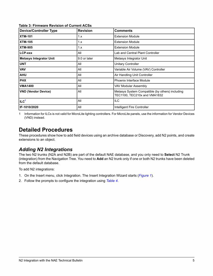
Table 3: Firmware Revision of Current ACSsCommentsRevisionDevice/Controller TypeExtension Module1.xXTM-101
Extension Module1.xXTM-105
Extension Module1.xXTM-905
Lab and Central Plant ControllerAllLCP-xxx
Metasys Integrator Unit9.0 or laterMetasys Integrator Unit
Unitary ControllerAllUNT
Variable Air Volume (VAV) ControllerAllVAV
Air Handling Unit ControllerAllAHU
Phoenix Interface ModuleAllPHX
VAV Modular AssemblyAllVMA1400
Metasys System Compatible (by others) includingTEC1100, TEC210x and VMA1832
AllVND (Vendor Device)
ILCAllILC1
Intelligent Fire ControllerAllIF-1010/2020
1 Information for ILCs is not valid for MicroLite lighting controllers. For MicroLite panels, use the information for Vendor Devices(VND) instead.
Detailed ProceduresThese procedures show how to add field devices using an archive database or Discovery, add N2 points, and createextensions to an object.
Adding N2 IntegrationsThe two N2 trunks (N2A and N2B) are part of the default NAE database, and you only need to Select N2 Trunk(integration) from the Navigation Tree. You need to Add an N2 trunk only if one or both N2 trunks have been deletedfrom the default database.
To add N2 integrations:
1. On the Insert menu, click Integration. The Insert Integration Wizard starts (Figure 1).2. Follow the prompts to configure the integration using Table 4.
5N2 Integration with the NAE Technical Bulletin
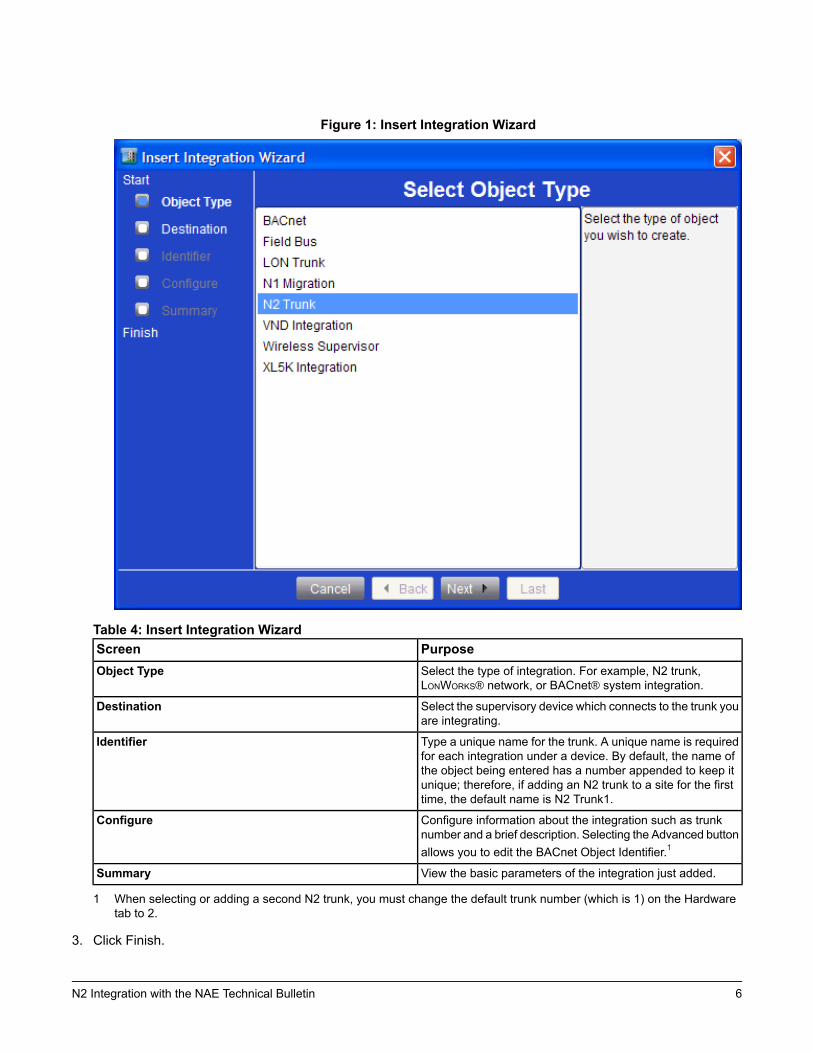
Figure 1: Insert Integration Wizard
Table 4: Insert Integration WizardPurposeScreenSelect the type of integration. For example, N2 trunk,LONWORKS® network, or BACnet® system integration.
Object Type
Select the supervisory device which connects to the trunk youare integrating.
Destination
Type a unique name for the trunk. A unique name is requiredfor each integration under a device. By default, the name ofthe object being entered has a number appended to keep itunique; therefore, if adding an N2 trunk to a site for the firsttime, the default name is N2 Trunk1.
Identifier
Configure information about the integration such as trunknumber and a brief description. Selecting the Advanced buttonallows you to edit the BACnet Object Identifier.1
Configure
View the basic parameters of the integration just added.Summary
1 When selecting or adding a second N2 trunk, you must change the default trunk number (which is 1) on the Hardwaretab to 2.
3. Click Finish.
6N2 Integration with the NAE Technical Bulletin

Adding N2 Field Devices Manually (Online or Offline)You can add N2 field devices manually whether your system is online or offline using the Insert Field Device Wizard.
To add N2 field devices manually:
1. On the Insert menu, click Field Device. The Insert Field Device Wizard starts (Figure 2).
Figure 2: Insert Field Device Wizard Destination Screen
2. Select the trunk where you want to insert the device and click Next. The Insert Field Device Wizard SelectDefinition screen appears (Figure 3).
3. On the Select Definition Mode screen, select the Manual device definition radio button.
Note: When using the SCT, the Assisted device definition radio button appears dimmed because that methodis unavailable when the system is offline.
7N2 Integration with the NAE Technical Bulletin
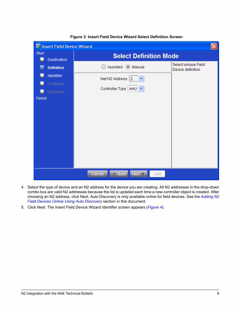
Figure 3: Insert Field Device Wizard Select Definition Screen
4. Select the type of device and an N2 address for the device you are creating. All N2 addresses in the drop-downcombo box are valid N2 addresses because the list is updated each time a new controller object is created. Afterchoosing an N2 address, click Next. Auto Discovery is only available online for field devices. See the Adding N2Field Devices Online Using Auto Discovery section in this document.
5. Click Next. The Insert Field Device Wizard Identifier screen appears (Figure 4).
8N2 Integration with the NAE Technical Bulletin
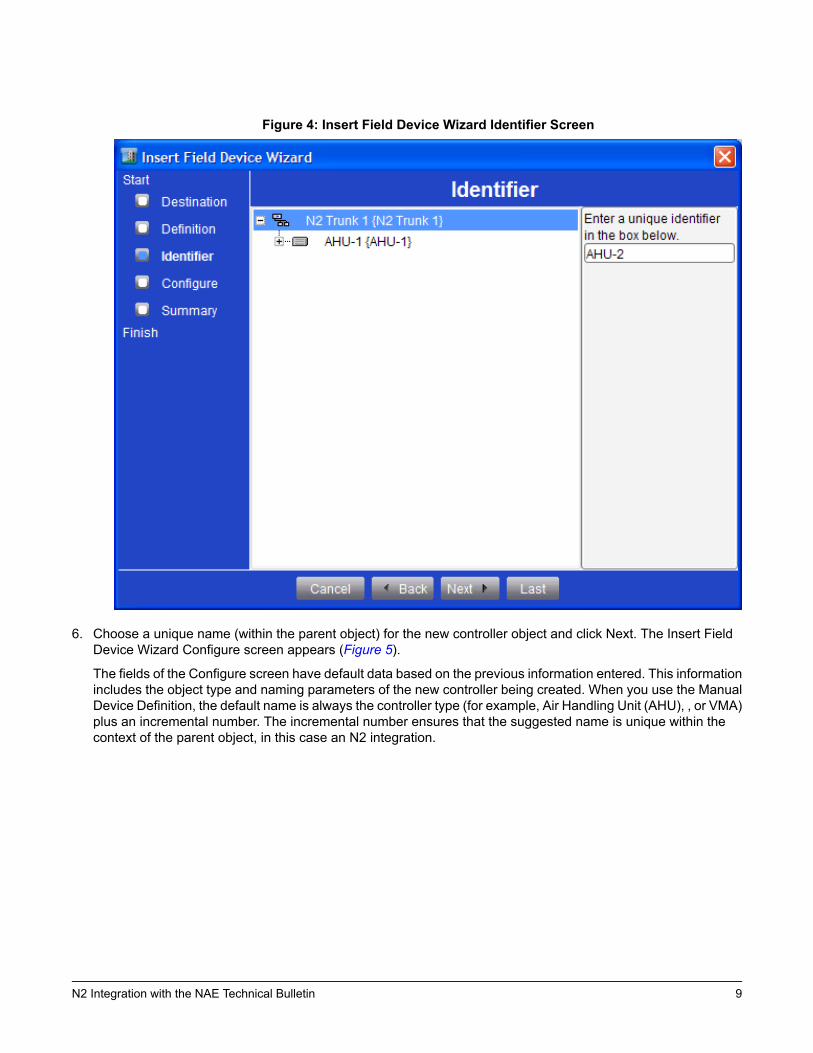
Figure 4: Insert Field Device Wizard Identifier Screen
6. Choose a unique name (within the parent object) for the new controller object and click Next. The Insert FieldDevice Wizard Configure screen appears (Figure 5).
The fields of the Configure screen have default data based on the previous information entered. This informationincludes the object type and naming parameters of the new controller being created. When you use the ManualDevice Definition, the default name is always the controller type (for example, Air Handling Unit (AHU), , or VMA)plus an incremental number. The incremental number ensures that the suggested name is unique within thecontext of the parent object, in this case an N2 integration.
9N2 Integration with the NAE Technical Bulletin
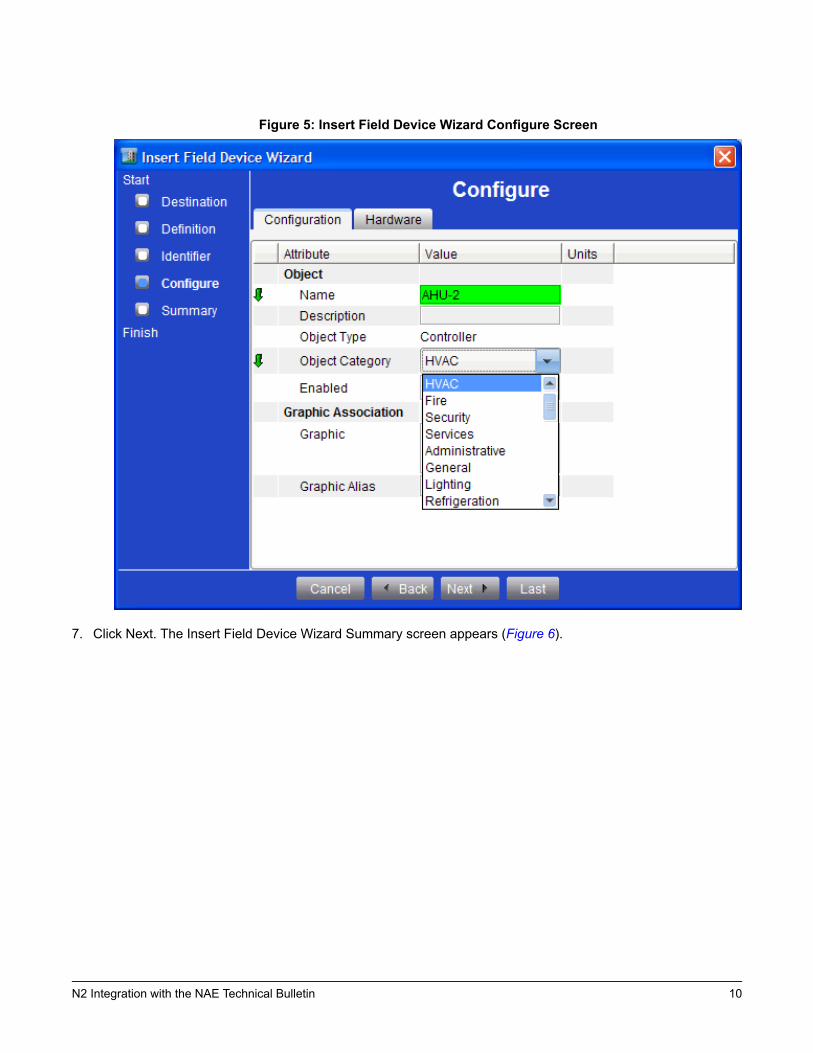
Figure 5: Insert Field Device Wizard Configure Screen
7. Click Next. The Insert Field Device Wizard Summary screen appears (Figure 6).
10N2 Integration with the NAE Technical Bulletin
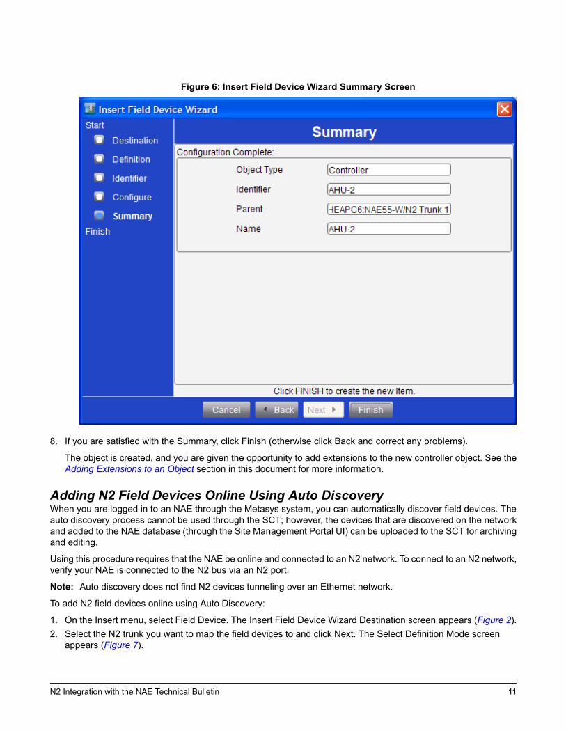
Figure 6: Insert Field Device Wizard Summary Screen
8. If you are satisfied with the Summary, click Finish (otherwise click Back and correct any problems).
The object is created, and you are given the opportunity to add extensions to the new controller object. See theAdding Extensions to an Object section in this document for more information.
Adding N2 Field Devices Online Using Auto DiscoveryWhen you are logged in to an NAE through the Metasys system, you can automatically discover field devices. Theauto discovery process cannot be used through the SCT; however, the devices that are discovered on the networkand added to the NAE database (through the Site Management Portal UI) can be uploaded to the SCT for archivingand editing.
Using this procedure requires that the NAE be online and connected to an N2 network. To connect to an N2 network,verify your NAE is connected to the N2 bus via an N2 port.
Note: Auto discovery does not find N2 devices tunneling over an Ethernet network.
To add N2 field devices online using Auto Discovery:
1. On the Insert menu, select Field Device. The Insert Field Device Wizard Destination screen appears (Figure 2).2. Select the N2 trunk you want to map the field devices to and click Next. The Select Definition Mode screen
appears (Figure 7).
11N2 Integration with the NAE Technical Bulletin
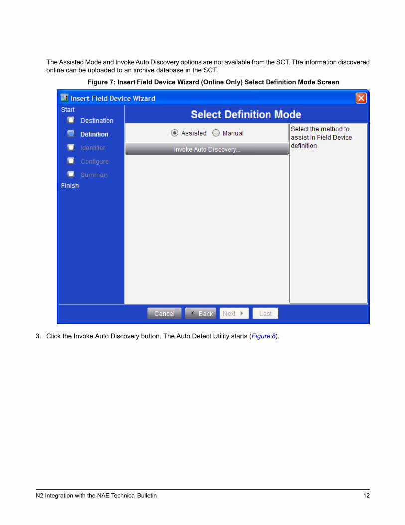
The Assisted Mode and Invoke Auto Discovery options are not available from the SCT. The information discoveredonline can be uploaded to an archive database in the SCT.
Figure 7: Insert Field Device Wizard (Online Only) Select Definition Mode Screen
3. Click the Invoke Auto Discovery button. The Auto Detect Utility starts (Figure 8).
12N2 Integration with the NAE Technical Bulletin
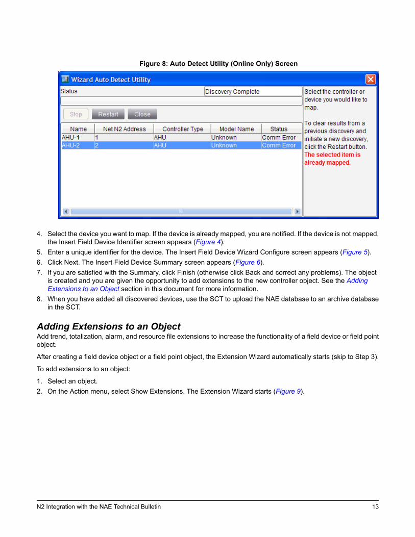
Figure 8: Auto Detect Utility (Online Only) Screen
4. Select the device you want to map. If the device is already mapped, you are notified. If the device is not mapped,the Insert Field Device Identifier screen appears (Figure 4).
5. Enter a unique identifier for the device. The Insert Field Device Wizard Configure screen appears (Figure 5).6. Click Next. The Insert Field Device Summary screen appears (Figure 6).7. If you are satisfied with the Summary, click Finish (otherwise click Back and correct any problems). The object
is created and you are given the opportunity to add extensions to the new controller object. See the AddingExtensions to an Object section in this document for more information.
8. When you have added all discovered devices, use the SCT to upload the NAE database to an archive databasein the SCT.
Adding Extensions to an ObjectAdd trend, totalization, alarm, and resource file extensions to increase the functionality of a field device or field pointobject.
After creating a field device object or a field point object, the Extension Wizard automatically starts (skip to Step 3).
To add extensions to an object:
1. Select an object.2. On the Action menu, select Show Extensions. The Extension Wizard starts (Figure 9).
13N2 Integration with the NAE Technical Bulletin
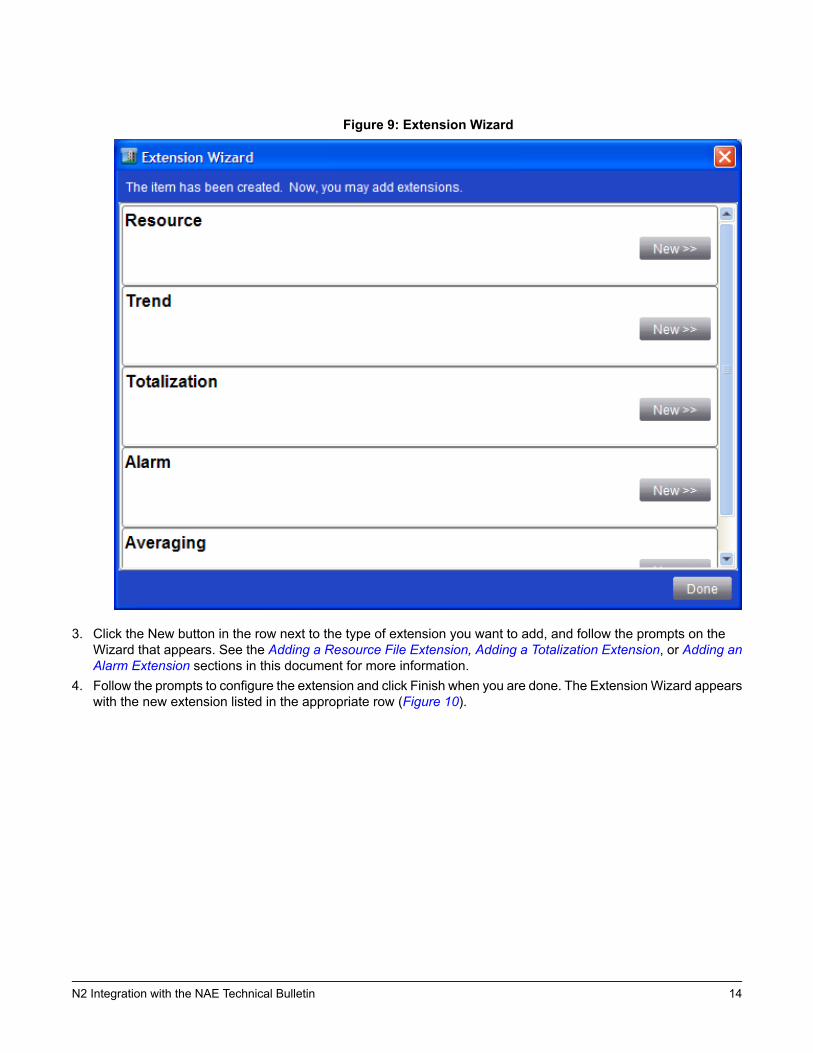
Figure 9: Extension Wizard
3. Click the New button in the row next to the type of extension you want to add, and follow the prompts on theWizard that appears. See the Adding a Resource File Extension, Adding a Totalization Extension, or Adding anAlarm Extension sections in this document for more information.
4. Follow the prompts to configure the extension and click Finish when you are done. The ExtensionWizard appearswith the new extension listed in the appropriate row (Figure 10).
14N2 Integration with the NAE Technical Bulletin
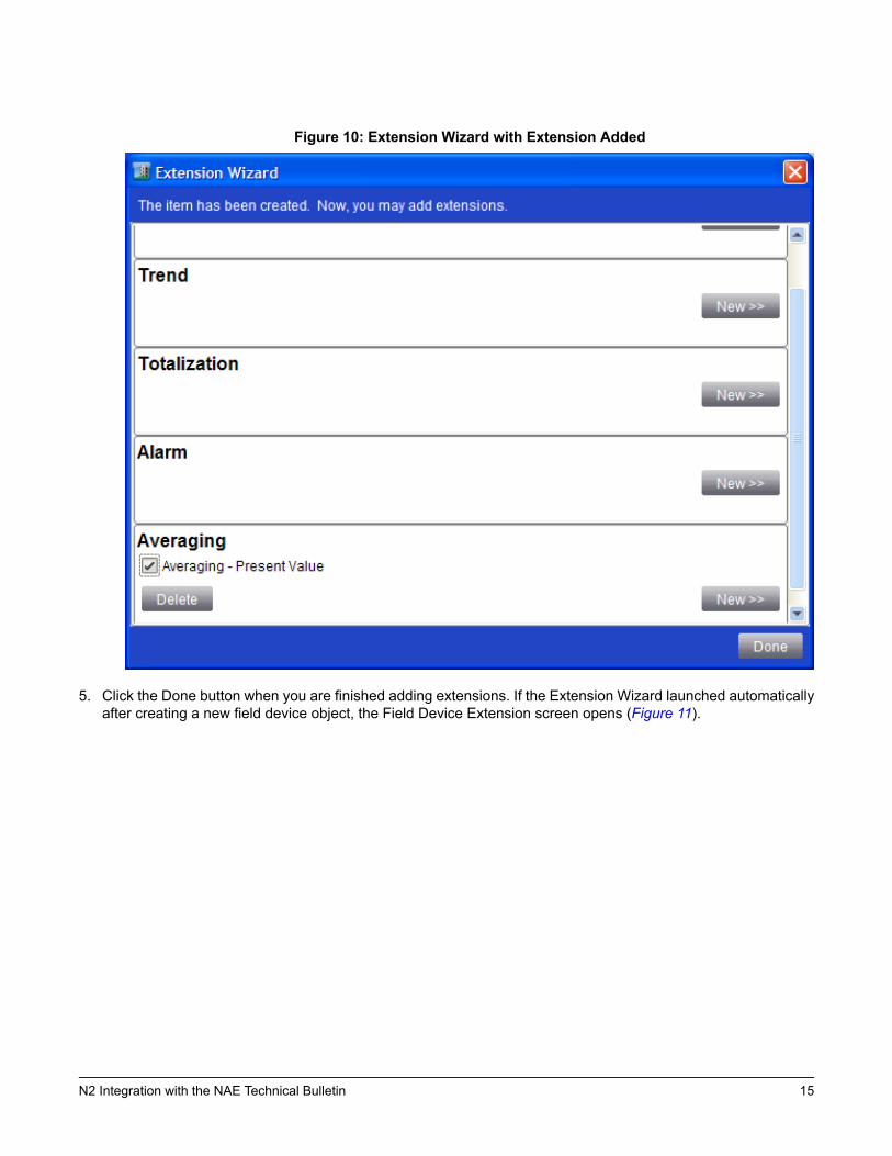
Figure 10: Extension Wizard with Extension Added
5. Click the Done button when you are finished adding extensions. If the Extension Wizard launched automaticallyafter creating a new field device object, the Field Device Extension screen opens (Figure 11).
15N2 Integration with the NAE Technical Bulletin
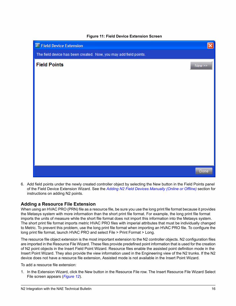
Figure 11: Field Device Extension Screen
6. Add field points under the newly created controller object by selecting the New button in the Field Points panelof the Field Device Extension Wizard. See the Adding N2 Field Devices Manually (Online or Offline) section forinstructions on adding N2 points.
Adding a Resource File ExtensionWhen using an HVAC PRO (PRN) file as a resource file, be sure you use the long print file format because it providesthe Metasys system with more information than the short print file format. For example, the long print file formatimports the units of measure while the short file format does not import this information into the Metasys system.The short print file format imports metric HVAC PRO files with imperial attributes that must be individually changedto Metric. To prevent this problem, use the long print file format when importing an HVAC PRO file. To configure thelong print file format, launch HVAC PRO and select File > Print Format > Long.
The resource file object extension is the most important extension to the N2 controller objects. N2 configuration filesare imported in the Resource File Wizard. These files provide predefined point information that is used for the creationof N2 point objects in the Insert Field Point Wizard. Resource files enable the assisted point definition mode in theInsert Point Wizard. They also provide the view information used in the Engineering view of the N2 trunks. If the N2device does not have a resource file extension, Assisted mode is not available in the Insert Point Wizard.
To add a resource file extension:
1. In the Extension Wizard, click the New button in the Resource File row. The Insert Resource File Wizard SelectFile screen appears (Figure 12).
16N2 Integration with the NAE Technical Bulletin
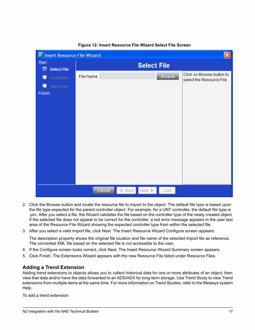
Figure 12: Insert Resource File Wizard Select File Screen
2. Click the Browse button and locate the resource file to import to the object. The default file type is based uponthe file type expected for the parent-controller object. For example, for a UNT controller, the default file type is.prn. After you select a file, the Wizard validates the file based on the controller type of the newly created object.If the selected file does not appear to be correct for the controller, a red error message appears in the user textarea of the Resource File Wizard showing the expected controller type from within the selected file.
3. After you select a valid import file, click Next. The Insert Resource Wizard Configure screen appears.
The description property shows the original file location and file name of the selected import file as reference.The converted XML file based on the selected file is not accessible to the user.
4. If the Configure screen looks correct, click Next. The Insert Resource Wizard Summary screen appears.5. Click Finish. The Extensions Wizard appears with the new Resource File listed under Resource Files.
Adding a Trend ExtensionAdding trend extensions to objects allows you to collect historical data for one or more attributes of an object, thenview that data and/or have the data forwarded to an ADS/ADX for long-term storage. Use Trend Study to view Trendextensions frommultiple items at the same time. For more information on Trend Studies, refer to the Metasys systemHelp.
To add a trend extension:
17N2 Integration with the NAE Technical Bulletin
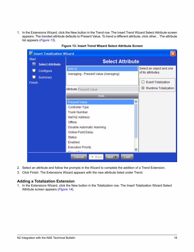
1. In the Extensions Wizard, click the New button in the Trend row. The Insert Trend Wizard Select Attribute screenappears. The trended attribute defaults to Present Value. To trend a different attribute, click other... The attributelist appears (Figure 13).
Figure 13: Insert Trend Wizard Select Attribute Screen
2. Select an attribute and follow the prompts in the Wizard to complete the addition of a Trend Extension.3. Click Finish. The Extensions Wizard appears with the new attribute listed under Trend.
Adding a Totalization Extension1. In the Extensions Wizard, click the New button in the Totalization row. The Insert Totalization Wizard Select
Attribute screen appears (Figure 14).
18N2 Integration with the NAE Technical Bulletin
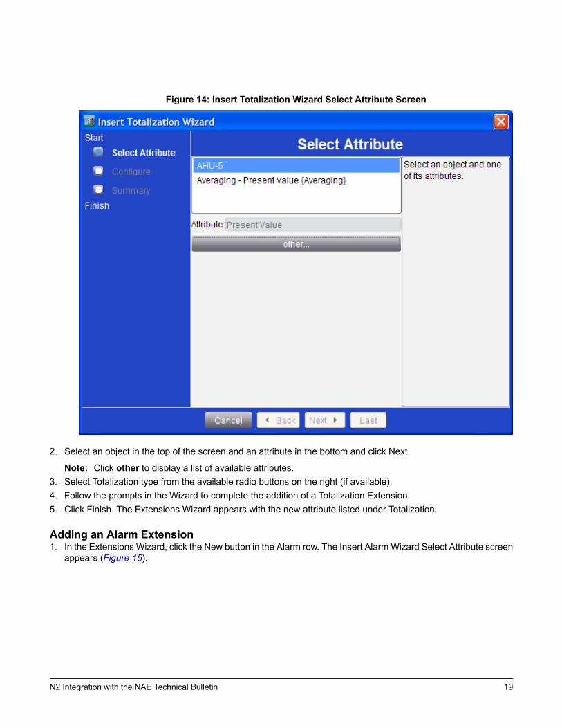
Figure 14: Insert Totalization Wizard Select Attribute Screen
2. Select an object in the top of the screen and an attribute in the bottom and click Next.
Note: Click other to display a list of available attributes.3. Select Totalization type from the available radio buttons on the right (if available).4. Follow the prompts in the Wizard to complete the addition of a Totalization Extension.5. Click Finish. The Extensions Wizard appears with the new attribute listed under Totalization.
Adding an Alarm Extension1. In the Extensions Wizard, click the New button in the Alarm row. The Insert AlarmWizard Select Attribute screen
appears (Figure 15).
19N2 Integration with the NAE Technical Bulletin

Figure 15: Insert Alarm Wizard Select Attribute Screen
2. Select an object you want to add the Alarm extension to in the top of the screen and an attribute in the bottomand click Next.
Note: Click other to display a list of available attributes.3. Follow the prompts in the Wizard to complete the addition of an Alarm Extension.4. Click Finish. The Extensions Wizard appears with the new attribute listed under Alarm.
Adding an Averaging Extension1. In the ExtensionsWizard, click the New button in the Averaging row. The Insert AveragingWizard Select Attribute
screen appears (Figure 16).
20N2 Integration with the NAE Technical Bulletin
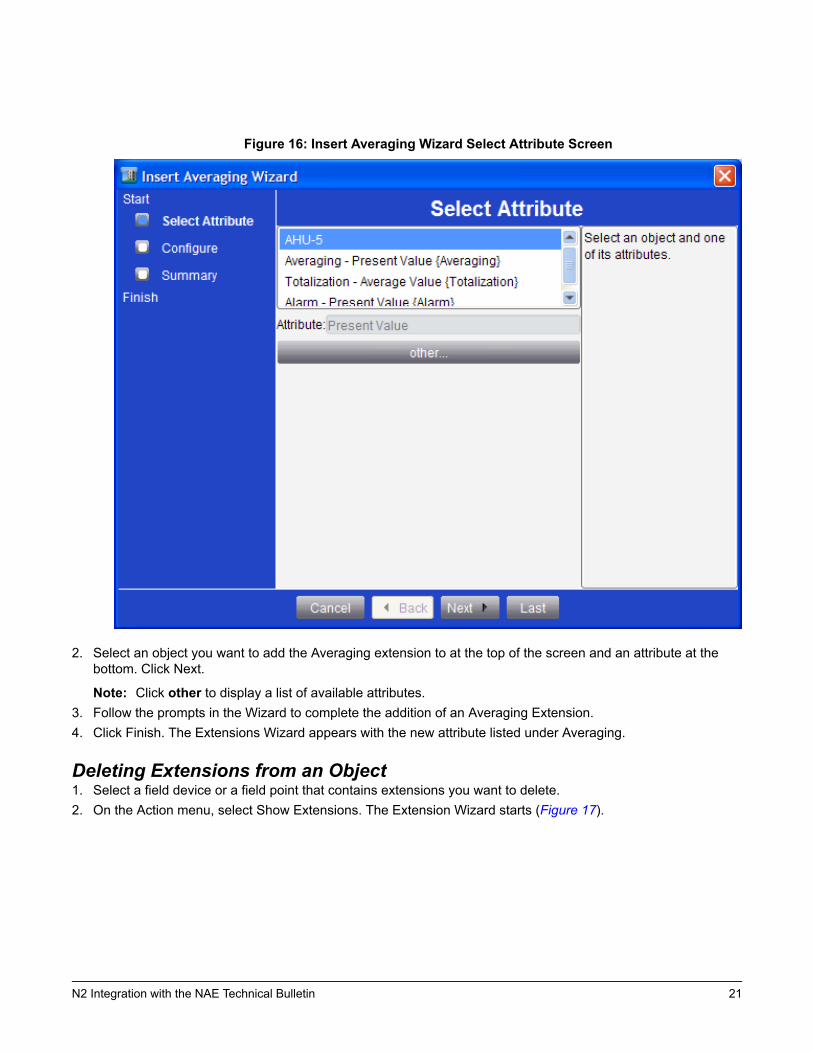
Figure 16: Insert Averaging Wizard Select Attribute Screen
2. Select an object you want to add the Averaging extension to at the top of the screen and an attribute at thebottom. Click Next.
Note: Click other to display a list of available attributes.3. Follow the prompts in the Wizard to complete the addition of an Averaging Extension.4. Click Finish. The Extensions Wizard appears with the new attribute listed under Averaging.
Deleting Extensions from an Object1. Select a field device or a field point that contains extensions you want to delete.2. On the Action menu, select Show Extensions. The Extension Wizard starts (Figure 17).
21N2 Integration with the NAE Technical Bulletin
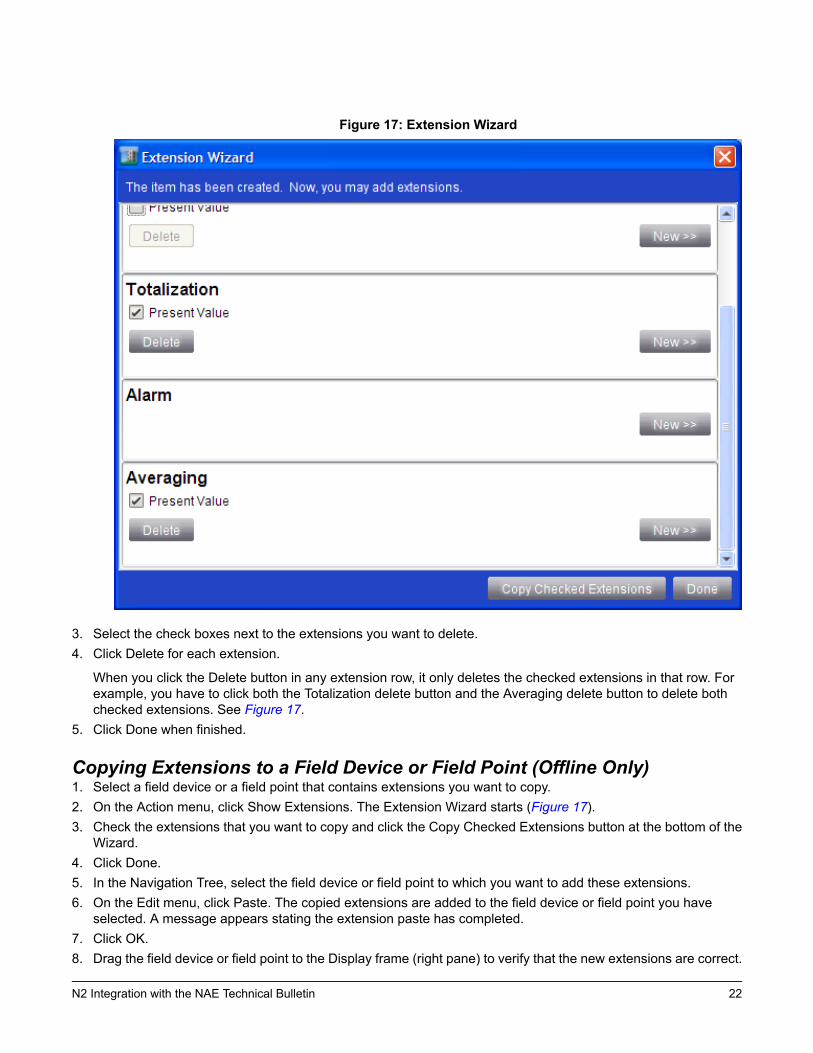
Figure 17: Extension Wizard
3. Select the check boxes next to the extensions you want to delete.4. Click Delete for each extension.
When you click the Delete button in any extension row, it only deletes the checked extensions in that row. Forexample, you have to click both the Totalization delete button and the Averaging delete button to delete bothchecked extensions. See Figure 17.
5. Click Done when finished.
Copying Extensions to a Field Device or Field Point (Offline Only)1. Select a field device or a field point that contains extensions you want to copy.2. On the Action menu, click Show Extensions. The Extension Wizard starts (Figure 17).3. Check the extensions that you want to copy and click the Copy Checked Extensions button at the bottom of the
Wizard.4. Click Done.5. In the Navigation Tree, select the field device or field point to which you want to add these extensions.6. On the Edit menu, click Paste. The copied extensions are added to the field device or field point you have
selected. A message appears stating the extension paste has completed.7. Click OK.8. Drag the field device or field point to the Display frame (right pane) to verify that the new extensions are correct.
22N2 Integration with the NAE Technical Bulletin
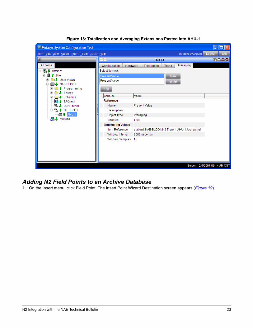
Figure 18: Totalization and Averaging Extensions Pasted into AHU-1
Adding N2 Field Points to an Archive Database1. On the Insert menu, click Field Point. The Insert Point Wizard Destination screen appears (Figure 19).
23N2 Integration with the NAE Technical Bulletin
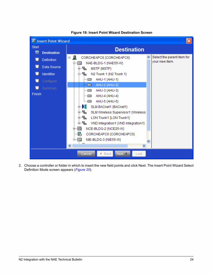
Figure 19: Insert Point Wizard Destination Screen
2. Choose a controller or folder in which to insert the new field points and click Next. The Insert Point Wizard SelectDefinition Mode screen appears (Figure 20).
24N2 Integration with the NAE Technical Bulletin
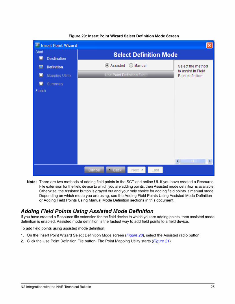
Figure 20: Insert Point Wizard Select Definition Mode Screen
Note: There are two methods of adding field points in the SCT and online UI. If you have created a ResourceFile extension for the field device to which you are adding points, then Assisted mode definition is available.Otherwise, the Assisted button is grayed out and your only choice for adding field points is manual mode.Depending on which mode you are using, see the Adding Field Points Using Assisted Mode Definitionor Adding Field Points Using Manual Mode Definition sections in this document.
Adding Field Points Using Assisted Mode DefinitionIf you have created a Resource file extension for the field device to which you are adding points, then assisted modedefinition is enabled. Assisted mode definition is the fastest way to add field points to a field device.
To add field points using assisted mode definition:
1. On the Insert Point Wizard Select Definition Mode screen (Figure 20), select the Assisted radio button.2. Click the Use Point Definition File button. The Point Mapping Utility starts (Figure 21).
25N2 Integration with the NAE Technical Bulletin
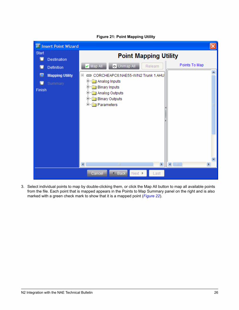
Figure 21: Point Mapping Utility
3. Select individual points to map by double-clicking them, or click the Map All button to map all available pointsfrom the file. Each point that is mapped appears in the Points to Map Summary panel on the right and is alsomarked with a green check mark to show that it is a mapped point (Figure 22).
26N2 Integration with the NAE Technical Bulletin
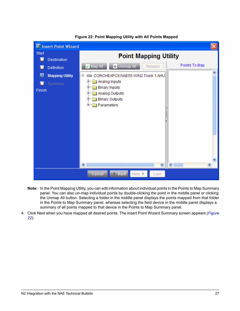
Figure 22: Point Mapping Utility with All Points Mapped
Note: In the Point Mapping Utility, you can edit information about individual points in the Points to Map Summarypanel. You can also un-map individual points by double-clicking the point in the middle panel or clickingthe Unmap All button. Selecting a folder in the middle panel displays the points mapped from that folderin the Points to Map Summary panel, whereas selecting the field device in the middle panel displays asummary of all points mapped to that device in the Points to Map Summary panel.
4. Click Next when you have mapped all desired points. The Insert Point Wizard Summary screen appears (Figure22).
27N2 Integration with the NAE Technical Bulletin
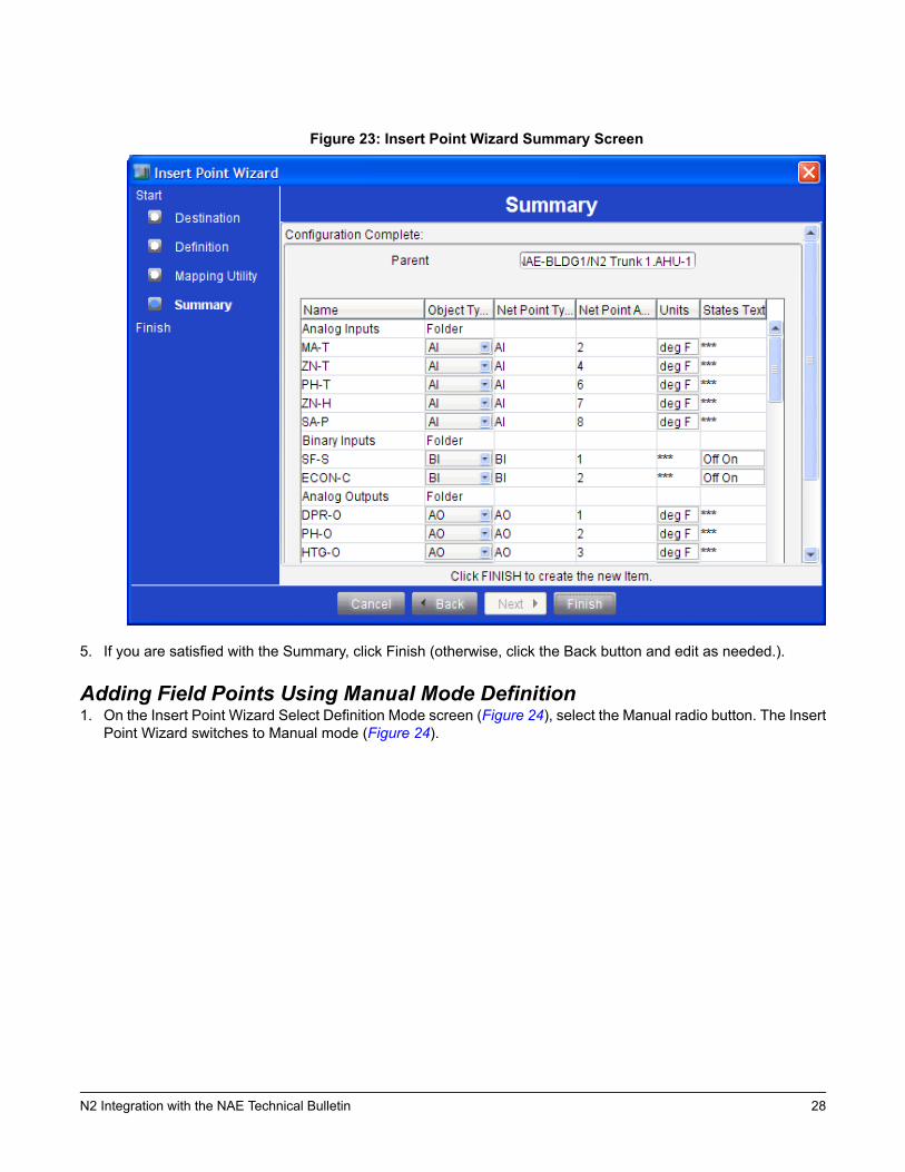
Figure 23: Insert Point Wizard Summary Screen
5. If you are satisfied with the Summary, click Finish (otherwise, click the Back button and edit as needed.).
Adding Field Points Using Manual Mode Definition1. On the Insert Point Wizard Select Definition Mode screen (Figure 24), select the Manual radio button. The Insert
Point Wizard switches to Manual mode (Figure 24).
28N2 Integration with the NAE Technical Bulletin
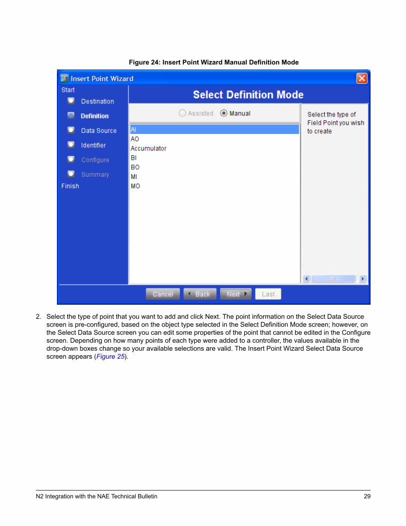
Figure 24: Insert Point Wizard Manual Definition Mode
2. Select the type of point that you want to add and click Next. The point information on the Select Data Sourcescreen is pre-configured, based on the object type selected in the Select Definition Mode screen; however, onthe Select Data Source screen you can edit some properties of the point that cannot be edited in the Configurescreen. Depending on how many points of each type were added to a controller, the values available in thedrop-down boxes change so your available selections are valid. The Insert Point Wizard Select Data Sourcescreen appears (Figure 25).
29N2 Integration with the NAE Technical Bulletin
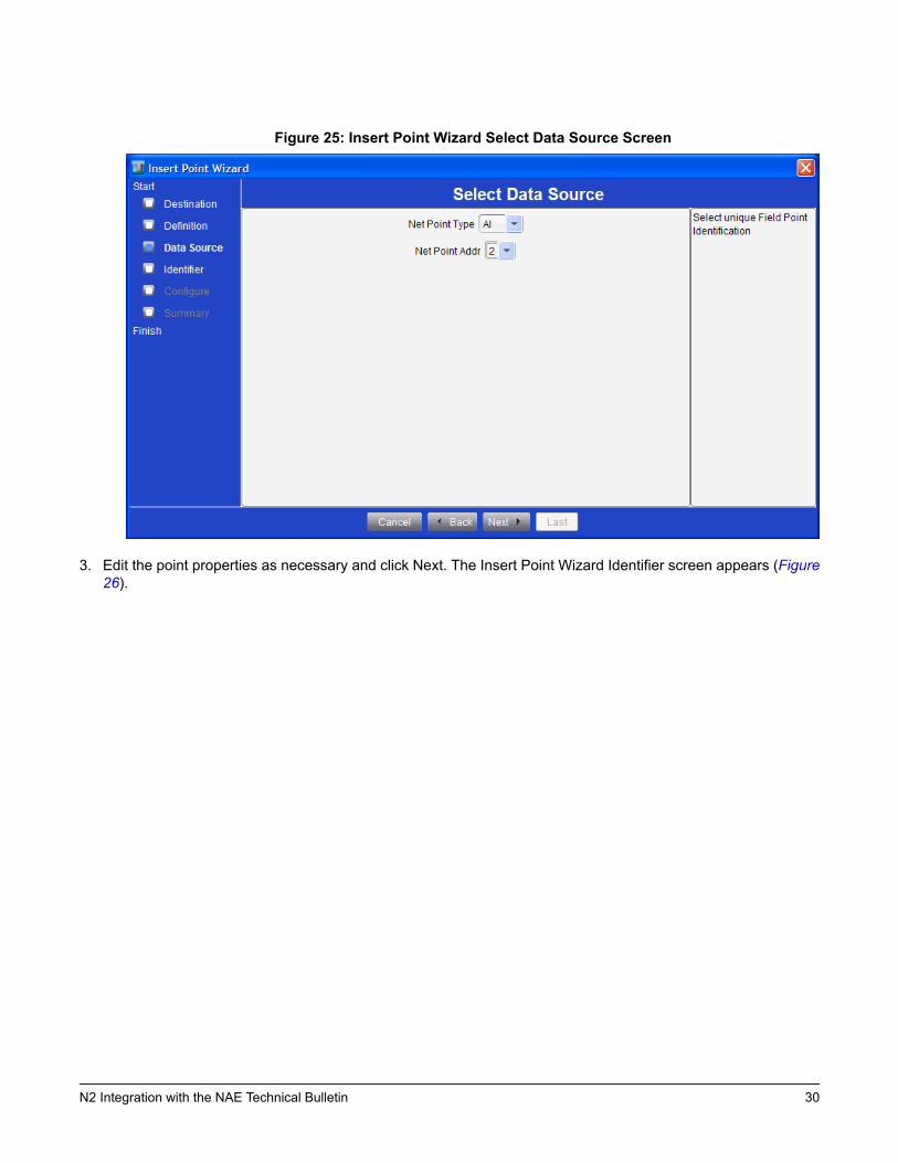
Figure 25: Insert Point Wizard Select Data Source Screen
3. Edit the point properties as necessary and click Next. The Insert Point Wizard Identifier screen appears (Figure26).
30N2 Integration with the NAE Technical Bulletin

Figure 26: Insert Point Wizard Identifier Screen
4. Enter a unique name for the new field point. The default name is based on the object type of the new field point.5. Click Next. The Insert Point Wizard Configure screen appears (Figure 27).
31N2 Integration with the NAE Technical Bulletin
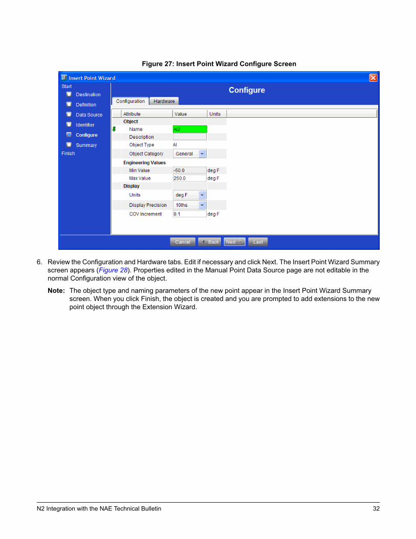
Figure 27: Insert Point Wizard Configure Screen
6. Review the Configuration and Hardware tabs. Edit if necessary and click Next. The Insert Point Wizard Summaryscreen appears (Figure 28). Properties edited in the Manual Point Data Source page are not editable in thenormal Configuration view of the object.
Note: The object type and naming parameters of the new point appear in the Insert Point Wizard Summaryscreen. When you click Finish, the object is created and you are prompted to add extensions to the newpoint object through the Extension Wizard.
32N2 Integration with the NAE Technical Bulletin

Figure 28: Insert Point Wizard Summary Screen
7. Click Finish. Otherwise, click the Back button and edit as needed.
N2 FEC, FAC, and VMA Point LimitsAt CCT 10.1, FECs, FACs, and VMAs can be defined as certain N2 devices. These devices include AHUs, UNTs,VAVs, and vendor devices. The following tables define the point limits of the new devices. To determine the appropriatepoint limits, use these tables and the tables for the devices which you are defining them as. In all cases, use thelower of the point limits of the N2 FEC and of the device it is defined as. For example, if you are defining an FEC1611as an AHU, your point limit for AIs is 8, as defined in the AHU Point Mapping to NAEs table, rather than the potentialof 12 shown in Table 6.
Table 5: Point Limitations of FAC2611, FAC2612, and FAC3611Network Point AddressNetwork Point Type1-50AI
1-50BI
1-50AO
1-50BO
1-256ADF
1-256ADI
1-256BD
Table 6: Point Limitations of FEC1611 and FEC2611Network Point AddressNetwork Point Type1-12AI
1-12BI
33N2 Integration with the NAE Technical Bulletin
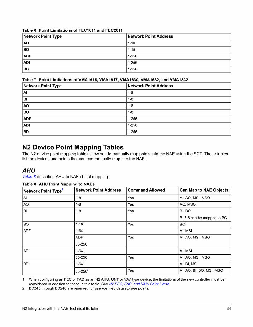
Table 6: Point Limitations of FEC1611 and FEC2611Network Point AddressNetwork Point Type1-10AO
1-15BO
1-256ADF
1-256ADI
1-256BD
Table 7: Point Limitations of VMA1615, VMA1617, VMA1630, VMA1632, and VMA1832Network Point AddressNetwork Point Type1-8AI
1-8BI
1-8AO
1-8BO
1-256ADF
1-256ADI
1-256BD
N2 Device Point Mapping TablesThe N2 device point mapping tables allow you to manually map points into the NAE using the SCT. These tableslist the devices and points that you can manually map into the NAE.
AHUTable 8 describes AHU to NAE object mapping.
Table 8: AHU Point Mapping to NAEsCan Map to NAE Objects:Command AllowedNetwork Point AddressNetwork Point Type1
AI, AO, MSI, MSOYes1-8AI
AO, MSOYes1-8AO
BI, BO
BI 7-8 can be mapped to PC
Yes1-8BI
BOYes1-10BO
AI, MSI1-64ADF
AI, AO, MSI, MSOYesADF
65-256
AI, MSI1-64ADI
AI, AO, MSI, MSOYes65-256
AI, BI, MSI1-64BD
AI, AO, BI, BO, MSI, MSOYes65-2562
1 When configuring an FEC or FAC as an N2 AHU, UNT or VAV type device, the limitations of the new controller must beconsidered in addition to those in this table. See N2 FEC, FAC, and VMA Point Limits.
2 BD245 through BD248 are reserved for user-defined data storage points.
34N2 Integration with the NAE Technical Bulletin
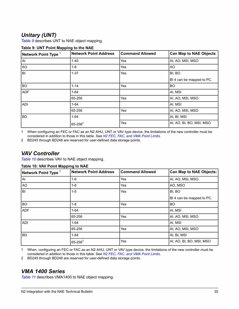
Unitary (UNT)Table 9 describes UNT to NAE object mapping.
Table 9: UNT Point Mapping to the NAECan Map to NAE ObjectsCommand AllowedNetwork Point AddressNetwork Point Type 1
AI, AO, MSI, MSOYes1-40AI
AOYes1-8AO
BI, BO
BI 4 can be mapped to PC.
Yes1-37BI
BOYes1-14BO
AI, MSI1-64ADF
AI, AO, MSI, MSOYes65-256
AI, MSI1-64ADI
AI, AO, MSI, MSOYes65-256
AI, BI, MSI1-64
65-2562BD
AI, AO, BI, BO, MSI, MSOYes
1 When configuring an FEC or FAC as an N2 AHU, UNT or VAV type device, the limitations of the new controller must beconsidered in addition to those in this table. See N2 FEC, FAC, and VMA Point Limits.
2 BD245 through BD248 are reserved for user-defined data storage points.
VAV ControllerTable 10 describes VAV to NAE object mapping.
Table 10: VAV Point Mapping to NAECan Map to NAE Objects:Command AllowedNetwork Point AddressNetwork Point Type 1
AI, AO, MSI, MSOYes1-6AI
AO, MSOYes1-8AO
BI, BO
BI 4 can be mapped to PC.
Yes1-5BI
BOYes1-8BO
AI, MSI1-64ADF
AI, AO, MSI, MSOYes65-256
AI, MSI1-64ADI
AI, AO, MSI, MSOYes65-256
AI, BI, MSI1-64BD
AI, AO, BI, BO, MSI, MSOYes65-2562
1 When. configuring an FEC or FAC as an N2 AHU, UNT or VAV type device, the limitations of the new controller must beconsidered in addition to those in this table. See N2 FEC, FAC, and VMA Point Limits.
2 BD245 through BD248 are reserved for user-defined data storage points.
VMA 1400 SeriesTable 11 describes VMA1400 to NAE object mapping.
35N2 Integration with the NAE Technical Bulletin
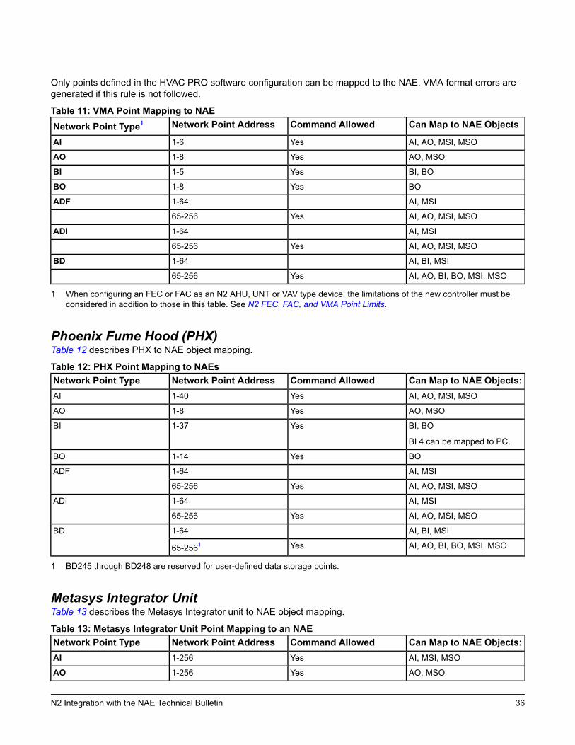
Only points defined in the HVAC PRO software configuration can be mapped to the NAE. VMA format errors aregenerated if this rule is not followed.
Table 11: VMA Point Mapping to NAECan Map to NAE ObjectsCommand AllowedNetwork Point AddressNetwork Point Type1
AI, AO, MSI, MSOYes1-6AI
AO, MSOYes1-8AO
BI, BOYes1-5BI
BOYes1-8BO
AI, MSI1-64ADF
AI, AO, MSI, MSOYes65-256
AI, MSI1-64ADI
AI, AO, MSI, MSOYes65-256
AI, BI, MSI1-64BD
AI, AO, BI, BO, MSI, MSOYes65-256
1 When configuring an FEC or FAC as an N2 AHU, UNT or VAV type device, the limitations of the new controller must beconsidered in addition to those in this table. See N2 FEC, FAC, and VMA Point Limits.
Phoenix Fume Hood (PHX)Table 12 describes PHX to NAE object mapping.
Table 12: PHX Point Mapping to NAEsCan Map to NAE Objects:Command AllowedNetwork Point AddressNetwork Point TypeAI, AO, MSI, MSOYes1-40AI
AO, MSOYes1-8AO
BI, BO
BI 4 can be mapped to PC.
Yes1-37BI
BOYes1-14BO
AI, MSI1-64ADF
AI, AO, MSI, MSOYes65-256
AI, MSI1-64ADI
AI, AO, MSI, MSOYes65-256
AI, BI, MSI1-64BD
AI, AO, BI, BO, MSI, MSOYes65-2561
1 BD245 through BD248 are reserved for user-defined data storage points.
Metasys Integrator UnitTable 13 describes the Metasys Integrator unit to NAE object mapping.
Table 13: Metasys Integrator Unit Point Mapping to an NAECan Map to NAE Objects:Command AllowedNetwork Point AddressNetwork Point TypeAI, MSI, MSOYes1-256AI
AO, MSOYes1-256AO
36N2 Integration with the NAE Technical Bulletin
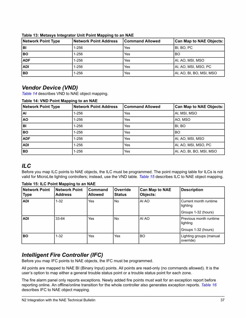
Table 13: Metasys Integrator Unit Point Mapping to an NAECan Map to NAE Objects:Command AllowedNetwork Point AddressNetwork Point TypeBI, BO, PCYes1-256BI
BOYes1-256BO
AI, AO, MSI, MSOYes1-256ADF
AI, AO, MSI, MSO, PCYes1-256ADI
AI, AO, BI, BO, MSI, MSOYes1-256BD
Vendor Device (VND)Table 14 describes VND to NAE object mapping.
Table 14: VND Point Mapping to an NAECan Map to NAE Objects:Command AllowedNetwork Point AddressNetwork Point TypeAI, MSI, MSOYes1-256AI
AO, MSOYes1-256AO
BI, BOYes1-256BI
BOYes1-256BO
AI, AO, MSI, MSOYes1-256ADF
AI, AO, MSI, MSO, PCYes1-256ADI
AI, AO, BI, BO, MSI, MSOYes1-256BD
ILCBefore you map ILC points to NAE objects, the ILC must be programmed. The point mapping table for ILCs is notvalid for MicroLite lighting controllers; instead, use the VND table. Table 15 describes ILC to NAE object mapping.
Table 15: ILC Point Mapping to an NAEDescriptionCan Map to NAE
Objects:OverrideStatus
CommandAllowed
Network PointAddress
Network PointType
Current month runtimelighting
Groups 1-32 (hours)
AI AONoYes1-32ADI
Previous month runtimelighting
Groups 1-32 (hours)
AI AONoYes33-64ADI
Lighting groups (manualoverride)
BOYesYes1-32BO
Intelligent Fire Controller (IFC)Before you map IFC points to NAE objects, the IFC must be programmed.
All points are mapped to NAE BI (Binary Input) points. All points are read-only (no commands allowed). It is theuser’s option to map either a general trouble status point or a trouble status point for each zone.
The fire alarm panel only reports exceptions. Newly added fire points must wait for an exception report beforereporting online. An offline/online transition for the whole controller also generates exception reports. Table 16describes IFC to NAE object mapping.
37N2 Integration with the NAE Technical Bulletin
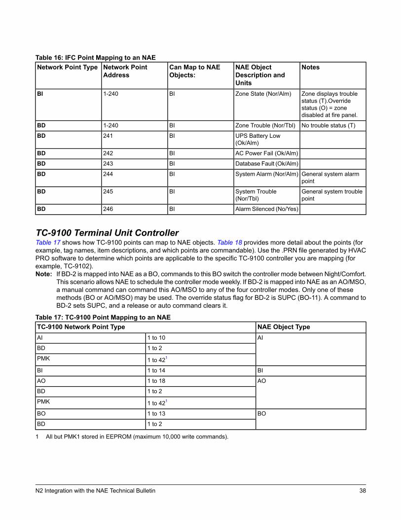
Table 16: IFC Point Mapping to an NAENotesNAE Object
Description andUnits
Can Map to NAEObjects:
Network PointAddress
Network Point Type
Zone displays troublestatus (T).Overridestatus (O) = zonedisabled at fire panel.
Zone State (Nor/Alm)BI1-240BI
No trouble status (T)Zone Trouble (Nor/Tbl)BI1-240BD
UPS Battery Low(Ok/Alm)
BI241BD
AC Power Fail (Ok/Alm)BI242BD
Database Fault (Ok/Alm)BI243BD
General system alarmpoint
System Alarm (Nor/Alm)BI244BD
General system troublepoint
System Trouble(Nor/Tbl)
BI245BD
Alarm Silenced (No/Yes)BI246BD
TC-9100 Terminal Unit ControllerTable 17 shows how TC-9100 points can map to NAE objects. Table 18 provides more detail about the points (forexample, tag names, item descriptions, and which points are commandable). Use the .PRN file generated by HVACPRO software to determine which points are applicable to the specific TC-9100 controller you are mapping (forexample, TC-9102).Note: If BD-2 is mapped into NAE as a BO, commands to this BO switch the controller mode between Night/Comfort.
This scenario allows NAE to schedule the controller mode weekly. If BD-2 is mapped into NAE as an AO/MSO,a manual command can command this AO/MSO to any of the four controller modes. Only one of thesemethods (BO or AO/MSO) may be used. The override status flag for BD-2 is SUPC (BO-11). A command toBD-2 sets SUPC, and a release or auto command clears it.
Table 17: TC-9100 Point Mapping to an NAENAE Object TypeTC-9100 Network Point TypeAI1 to 10AI
1 to 2BD
1 to 421PMK
BI1 to 14BI
AO1 to 18AO
1 to 2BD
1 to 421PMK
BO1 to 13BO
1 to 2BD
1 All but PMK1 stored in EEPROM (maximum 10,000 write commands).
38N2 Integration with the NAE Technical Bulletin
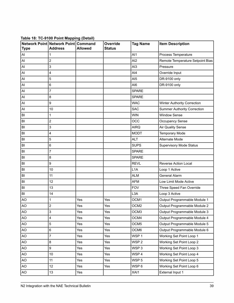
Table 18: TC-9100 Point Mapping (Detail)Item DescriptionTag NameOverride
StatusCommandAllowed
Network PointAddress
Network PointType
Process TemperatureAI11AI
Remote Temperature Setpoint BiasAI22AI
PressureAI33AI
Override InputAI44AI
DR-9100 onlyAI55AI
DR-9100 onlyAI66AI
SPARE7AI
SPARE8AI
Winter Authority CorrectionWAC9AI
Summer Authority CorrectionSAC10AI
Window SenseWIN1BI
Occupancy SenseOCC2BI
Air Quality SenseAIRQ3BI
Temporary ModeMODT4BI
Alternate ModeALT5BI
Supervisory Mode StatusSUPS6BI
SPARE7BI
SPARE8BI
Reverse Action LocalREVL9BI
Loop 1 ActiveL1A10BI
General AlarmALM11BI
Low Limit Mode ActiveAFM12BI
Three Speed Fan OverrideFOV13BI
Loop 3 ActiveL3A14BI
Output Programmable Module 1OCM1YesYes1AO
Output Programmable Module 2OCM2YesYes2AO
Output Programmable Module 3OCM3YesYes3AO
Output Programmable Module 4OCM4YesYes4AO
Output Programmable Module 5OCM5YesYes5AO
Output Programmable Module 6OCM6YesYes6AO
Working Set Point Loop 1WSP 1YesYes7AO
Working Set Point Loop 2WSP 2YesYes8AO
Working Set Point Loop 3WSP 3YesYes9AO
Working Set Point Loop 4WSP 4YesYes10AO
Working Set Point Loop 5WSP 5YesYes11AO
Working Set Point Loop 6WSP 6YesYes12AO
External Input 1XAI1Yes13AO
39N2 Integration with the NAE Technical Bulletin
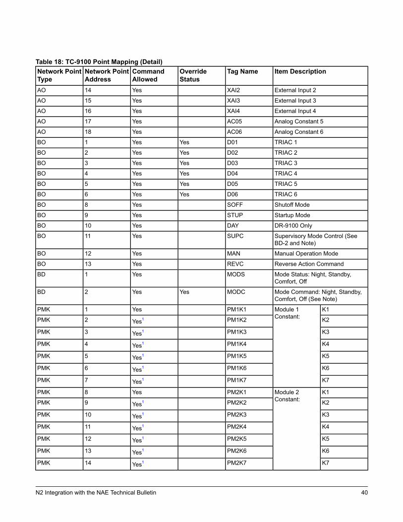
Table 18: TC-9100 Point Mapping (Detail)Item DescriptionTag NameOverride
StatusCommandAllowed
Network PointAddress
Network PointType
External Input 2XAI2Yes14AO
External Input 3XAI3Yes15AO
External Input 4XAI4Yes16AO
Analog Constant 5AC05Yes17AO
Analog Constant 6AC06Yes18AO
TRIAC 1D01YesYes1BO
TRIAC 2D02YesYes2BO
TRIAC 3D03YesYes3BO
TRIAC 4D04YesYes4BO
TRIAC 5D05YesYes5BO
TRIAC 6D06YesYes6BO
Shutoff ModeSOFFYes8BO
Startup ModeSTUPYes9BO
DR-9100 OnlyDAYYes10BO
Supervisory Mode Control (SeeBD-2 and Note)
SUPCYes11BO
Manual Operation ModeMANYes12BO
Reverse Action CommandREVCYes13BO
Mode Status: Night, Standby,Comfort, Off
MODSYes1BD
Mode Command: Night, Standby,Comfort, Off (See Note)
MODCYesYes2BD
K1Module 1Constant:
PM1K1Yes1PMK
K2PM1K2Yes12PMK
K3PM1K3Yes13PMK
K4PM1K4Yes14PMK
K5PM1K5Yes15PMK
K6PM1K6Yes16PMK
K7PM1K7Yes17PMK
K1Module 2Constant:
PM2K1Yes8PMK
K2PM2K2Yes19PMK
K3PM2K3Yes110PMK
K4PM2K4Yes111PMK
K5PM2K5Yes112PMK
K6PM2K6Yes113PMK
K7PM2K7Yes114PMK
40N2 Integration with the NAE Technical Bulletin
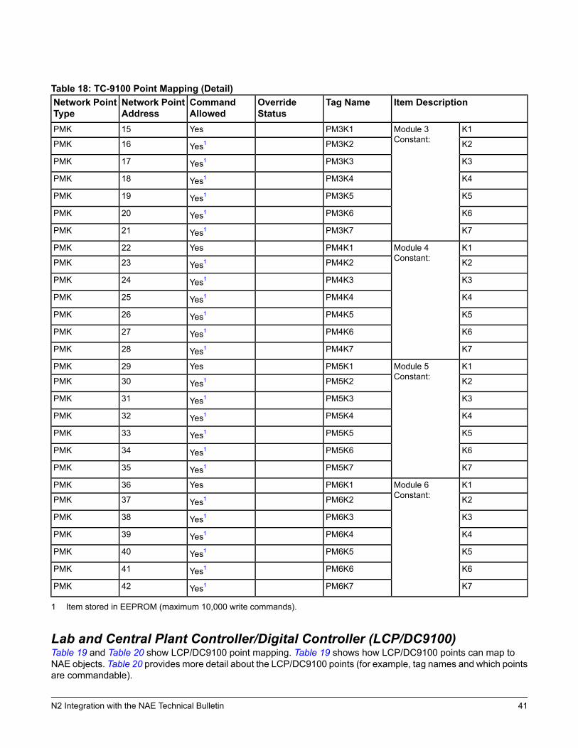
Table 18: TC-9100 Point Mapping (Detail)Item DescriptionTag NameOverride
StatusCommandAllowed
Network PointAddress
Network PointType
K1Module 3Constant:
PM3K1Yes15PMK
K2PM3K2Yes116PMK
K3PM3K3Yes117PMK
K4PM3K4Yes118PMK
K5PM3K5Yes119PMK
K6PM3K6Yes120PMK
K7PM3K7Yes121PMK
K1Module 4Constant:
PM4K1Yes22PMK
K2PM4K2Yes123PMK
K3PM4K3Yes124PMK
K4PM4K4Yes125PMK
K5PM4K5Yes126PMK
K6PM4K6Yes127PMK
K7PM4K7Yes128PMK
K1Module 5Constant:
PM5K1Yes29PMK
K2PM5K2Yes130PMK
K3PM5K3Yes131PMK
K4PM5K4Yes132PMK
K5PM5K5Yes133PMK
K6PM5K6Yes134PMK
K7PM5K7Yes135PMK
K1Module 6Constant:
PM6K1Yes36PMK
K2PM6K2Yes137PMK
K3PM6K3Yes138PMK
K4PM6K4Yes139PMK
K5PM6K5Yes140PMK
K6PM6K6Yes141PMK
K7PM6K7Yes142PMK
1 Item stored in EEPROM (maximum 10,000 write commands).
Lab and Central Plant Controller/Digital Controller (LCP/DC9100)Table 19 and Table 20 show LCP/DC9100 point mapping. Table 19 shows how LCP/DC9100 points can map toNAE objects. Table 20 provides more detail about the LCP/DC9100 points (for example, tag names and which pointsare commandable).
41N2 Integration with the NAE Technical Bulletin

Table 19: LCP/DC9100 Point Mapping to NAENAE Object TypeLCP/DC9100 Network Point TypeAIAI, ADF
AOADF
BIBI, BD
BOBO, BD
42N2 Integration with the NAE Technical Bulletin
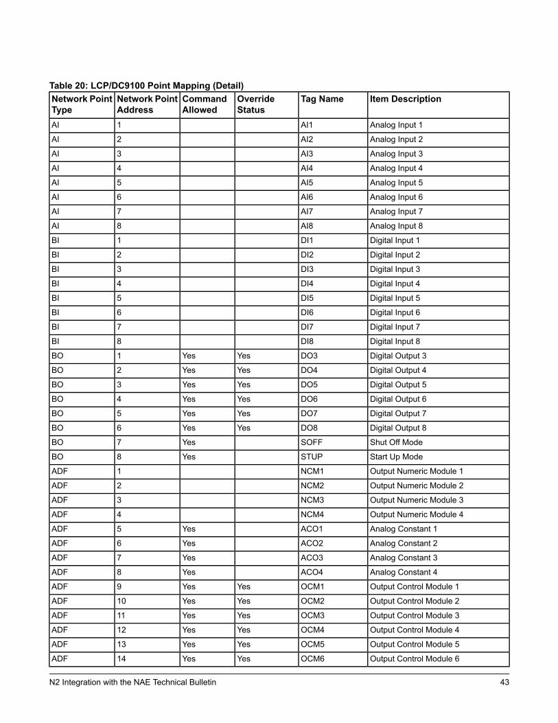
Table 20: LCP/DC9100 Point Mapping (Detail)Item DescriptionTag NameOverride
StatusCommandAllowed
Network PointAddress
Network PointType
Analog Input 1AI11AI
Analog Input 2AI22AI
Analog Input 3AI33AI
Analog Input 4AI44AI
Analog Input 5AI55AI
Analog Input 6AI66AI
Analog Input 7AI77AI
Analog Input 8AI88AI
Digital Input 1DI11BI
Digital Input 2DI22BI
Digital Input 3DI33BI
Digital Input 4DI44BI
Digital Input 5DI55BI
Digital Input 6DI66BI
Digital Input 7DI77BI
Digital Input 8DI88BI
Digital Output 3DO3YesYes1BO
Digital Output 4DO4YesYes2BO
Digital Output 5DO5YesYes3BO
Digital Output 6DO6YesYes4BO
Digital Output 7DO7YesYes5BO
Digital Output 8DO8YesYes6BO
Shut Off ModeSOFFYes7BO
Start Up ModeSTUPYes8BO
Output Numeric Module 1NCM11ADF
Output Numeric Module 2NCM22ADF
Output Numeric Module 3NCM33ADF
Output Numeric Module 4NCM44ADF
Analog Constant 1ACO1Yes5ADF
Analog Constant 2ACO2Yes6ADF
Analog Constant 3ACO3Yes7ADF
Analog Constant 4ACO4Yes8ADF
Output Control Module 1OCM1YesYes9ADF
Output Control Module 2OCM2YesYes10ADF
Output Control Module 3OCM3YesYes11ADF
Output Control Module 4OCM4YesYes12ADF
Output Control Module 5OCM5YesYes13ADF
Output Control Module 6OCM6YesYes14ADF
43N2 Integration with the NAE Technical Bulletin
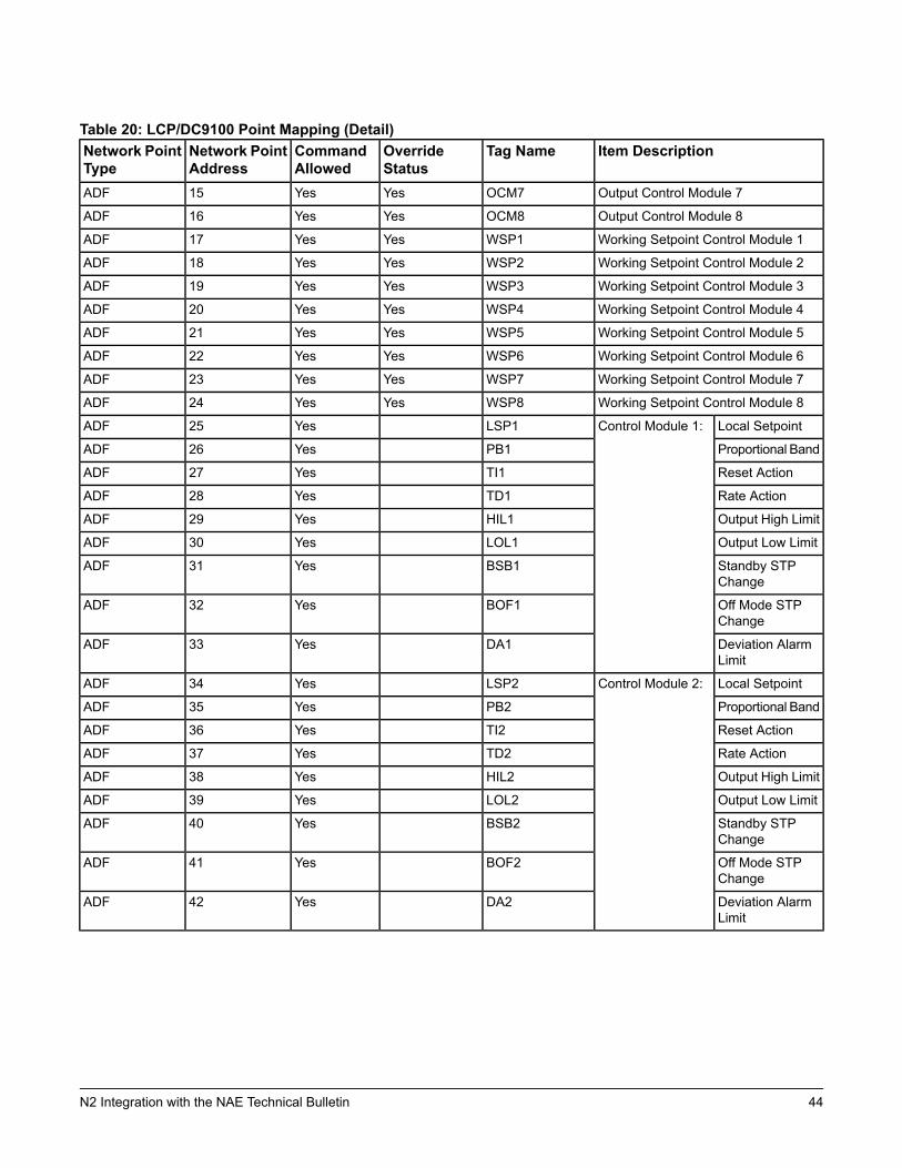
Table 20: LCP/DC9100 Point Mapping (Detail)Item DescriptionTag NameOverride
StatusCommandAllowed
Network PointAddress
Network PointType
Output Control Module 7OCM7YesYes15ADF
Output Control Module 8OCM8YesYes16ADF
Working Setpoint Control Module 1WSP1YesYes17ADF
Working Setpoint Control Module 2WSP2YesYes18ADF
Working Setpoint Control Module 3WSP3YesYes19ADF
Working Setpoint Control Module 4WSP4YesYes20ADF
Working Setpoint Control Module 5WSP5YesYes21ADF
Working Setpoint Control Module 6WSP6YesYes22ADF
Working Setpoint Control Module 7WSP7YesYes23ADF
Working Setpoint Control Module 8WSP8YesYes24ADF
Local SetpointControl Module 1:LSP1Yes25ADF
Proportional BandPB1Yes26ADF
Reset ActionTI1Yes27ADF
Rate ActionTD1Yes28ADF
Output High LimitHIL1Yes29ADF
Output Low LimitLOL1Yes30ADF
Standby STPChange
BSB1Yes31ADF
Off Mode STPChange
BOF1Yes32ADF
Deviation AlarmLimit
DA1Yes33ADF
Local SetpointControl Module 2:LSP2Yes34ADF
Proportional BandPB2Yes35ADF
Reset ActionTI2Yes36ADF
Rate ActionTD2Yes37ADF
Output High LimitHIL2Yes38ADF
Output Low LimitLOL2Yes39ADF
Standby STPChange
BSB2Yes40ADF
Off Mode STPChange
BOF2Yes41ADF
Deviation AlarmLimit
DA2Yes42ADF
44N2 Integration with the NAE Technical Bulletin
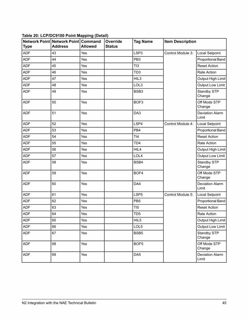
Table 20: LCP/DC9100 Point Mapping (Detail)Item DescriptionTag NameOverride
StatusCommandAllowed
Network PointAddress
Network PointType
Local SetpointControl Module 3:LSP3Yes43ADF
Proportional BandPB3Yes44ADF
Reset ActionTI3Yes45ADF
Rate ActionTD3Yes46ADF
Output High LimitHIL3Yes47ADF
Output Low LimitLOL3Yes48ADF
Standby STPChange
BSB3Yes49ADF
Off Mode STPChange
BOF3Yes50ADF
Deviation AlarmLimit
DA3Yes51ADF
Local SetpointControl Module 4:LSP4Yes52ADF
Proportional BandPB4Yes53ADF
Reset ActionTI4Yes54ADF
Rate ActionTD4Yes55ADF
Output High LimitHIL4Yes56ADF
Output Low LimitLOL4Yes57ADF
Standby STPChange
BSB4Yes58ADF
Off Mode STPChange
BOF4Yes59ADF
Deviation AlarmLimit
DA4Yes60ADF
Local SetpointControl Module 5:LSP5Yes61ADF
Proportional BandPB5Yes62ADF
Reset ActionTI5Yes63ADF
Rate ActionTD5Yes64ADF
Output High LimitHIL5Yes65ADF
Output Low LimitLOL5Yes66ADF
Standby STPChange
BSB5Yes67ADF
Off Mode STPChange
BOF5Yes68ADF
Deviation AlarmLimit
DA5Yes69ADF
45N2 Integration with the NAE Technical Bulletin
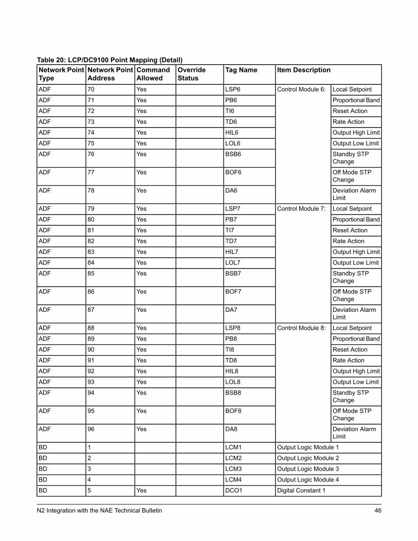
Table 20: LCP/DC9100 Point Mapping (Detail)Item DescriptionTag NameOverride
StatusCommandAllowed
Network PointAddress
Network PointType
Local SetpointControl Module 6:LSP6Yes70ADF
Proportional BandPB6Yes71ADF
Reset ActionTI6Yes72ADF
Rate ActionTD6Yes73ADF
Output High LimitHIL6Yes74ADF
Output Low LimitLOL6Yes75ADF
Standby STPChange
BSB6Yes76ADF
Off Mode STPChange
BOF6Yes77ADF
Deviation AlarmLimit
DA6Yes78ADF
Local SetpointControl Module 7:LSP7Yes79ADF
Proportional BandPB7Yes80ADF
Reset ActionTI7Yes81ADF
Rate ActionTD7Yes82ADF
Output High LimitHIL7Yes83ADF
Output Low LimitLOL7Yes84ADF
Standby STPChange
BSB7Yes85ADF
Off Mode STPChange
BOF7Yes86ADF
Deviation AlarmLimit
DA7Yes87ADF
Local SetpointControl Module 8:LSP8Yes88ADF
Proportional BandPB8Yes89ADF
Reset ActionTI8Yes90ADF
Rate ActionTD8Yes91ADF
Output High LimitHIL8Yes92ADF
Output Low LimitLOL8Yes93ADF
Standby STPChange
BSB8Yes94ADF
Off Mode STPChange
BOF8Yes95ADF
Deviation AlarmLimit
DA8Yes96ADF
Output Logic Module 1LCM11BD
Output Logic Module 2LCM22BD
Output Logic Module 3LCM33BD
Output Logic Module 4LCM44BD
Digital Constant 1DCO1Yes5BD
46N2 Integration with the NAE Technical Bulletin
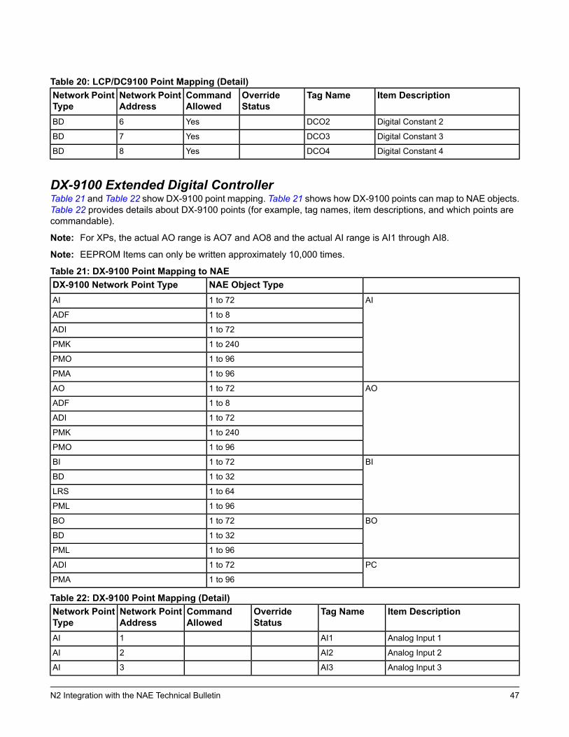
Table 20: LCP/DC9100 Point Mapping (Detail)Item DescriptionTag NameOverride
StatusCommandAllowed
Network PointAddress
Network PointType
Digital Constant 2DCO2Yes6BD
Digital Constant 3DCO3Yes7BD
Digital Constant 4DCO4Yes8BD
DX-9100 Extended Digital ControllerTable 21 and Table 22 show DX-9100 point mapping. Table 21 shows how DX-9100 points can map to NAE objects.Table 22 provides details about DX-9100 points (for example, tag names, item descriptions, and which points arecommandable).
Note: For XPs, the actual AO range is AO7 and AO8 and the actual AI range is AI1 through AI8.
Note: EEPROM Items can only be written approximately 10,000 times.
Table 21: DX-9100 Point Mapping to NAENAE Object TypeDX-9100 Network Point Type
AI1 to 72AI
1 to 8ADF
1 to 72ADI
1 to 240PMK
1 to 96PMO
1 to 96PMA
AO1 to 72AO
1 to 8ADF
1 to 72ADI
1 to 240PMK
1 to 96PMO
BI1 to 72BI
1 to 32BD
1 to 64LRS
1 to 96PML
BO1 to 72BO
1 to 32BD
1 to 96PML
PC1 to 72ADI
1 to 96PMA
Table 22: DX-9100 Point Mapping (Detail)Item DescriptionTag NameOverride
StatusCommandAllowed
Network PointAddress
Network PointType
Analog Input 1AI11AI
Analog Input 2AI22AI
Analog Input 3AI33AI
47N2 Integration with the NAE Technical Bulletin
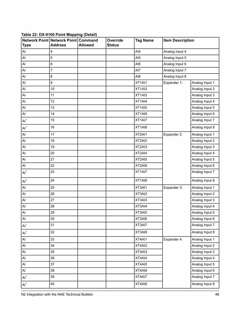
Table 22: DX-9100 Point Mapping (Detail)Item DescriptionTag NameOverride
StatusCommandAllowed
Network PointAddress
Network PointType
Analog Input 4AI44AI
Analog Input 5AI55AI
Analog Input 6AI66AI
Analog Input 7AI77AI
Analog Input 8AI88AI
Analog Input 1Expander 1:XT1AI19AI
Analog Input 2XT1AI210AI
Analog Input 3XT1AI311AI
Analog Input 4XT1AI412AI
Analog Input 5XT1AI513AI
Analog Input 6XT1AI614AI
Analog Input 7XT1AI715AI1
Analog Input 8XT1AI816AI1
Analog Input 1Expander 2:XT2AI117AI
Analog Input 2XT2AI218AI
Analog Input 3XT2AI319AI
Analog Input 4XT2AI420AI
Analog Input 5XT2AI521AI
Analog Input 6XT2AI622AI
Analog Input 7XT1AI723AI1
Analog Input 8XT1AI824AI1
Analog Input 1Expander 3:XT3AI125AI
Analog Input 2XT3AI226AI
Analog Input 3XT3AI327AI
Analog Input 4XT3AI428AI
Analog Input 5XT3AI529AI
Analog Input 6XT3AI630AI
Analog Input 7XT3AI731AI1
Analog Input 8XT3AI832AI1
Analog Input 1Expander 4:XT4AI133AI
Analog Input 2XT4AI234AI
Analog Input 3XT4AI335AI
Analog Input 4XT4AI436AI
Analog Input 5XT4AI537AI
Analog Input 6XT4AI638AI
Analog Input 7XT4AI739AI1
Analog Input 8XT4AI840AI1
48N2 Integration with the NAE Technical Bulletin
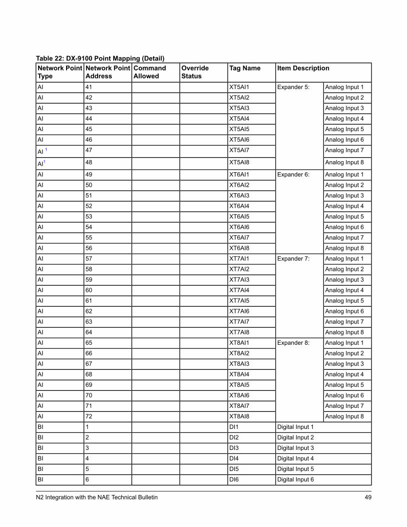
Table 22: DX-9100 Point Mapping (Detail)Item DescriptionTag NameOverride
StatusCommandAllowed
Network PointAddress
Network PointType
Analog Input 1Expander 5:XT5AI141AI
Analog Input 2XT5AI242AI
Analog Input 3XT5AI343AI
Analog Input 4XT5AI444AI
Analog Input 5XT5AI545AI
Analog Input 6XT5AI646AI
Analog Input 7XT5AI747AI 1
Analog Input 8XT5AI848AI1
Analog Input 1Expander 6:XT6AI149AI
Analog Input 2XT6AI250AI
Analog Input 3XT6AI351AI
Analog Input 4XT6AI452AI
Analog Input 5XT6AI553AI
Analog Input 6XT6AI654AI
Analog Input 7XT6AI755AI
Analog Input 8XT6AI856AI
Analog Input 1Expander 7:XT7AI157AI
Analog Input 2XT7AI258AI
Analog Input 3XT7AI359AI
Analog Input 4XT7AI460AI
Analog Input 5XT7AI561AI
Analog Input 6XT7AI662AI
Analog Input 7XT7AI763AI
Analog Input 8XT7AI864AI
Analog Input 1Expander 8:XT8AI165AI
Analog Input 2XT8AI266AI
Analog Input 3XT8AI367AI
Analog Input 4XT8AI468AI
Analog Input 5XT8AI569AI
Analog Input 6XT8AI670AI
Analog Input 7XT8AI771AI
Analog Input 8XT8AI872AI
Digital Input 1DI11BI
Digital Input 2DI22BI
Digital Input 3DI33BI
Digital Input 4DI44BI
Digital Input 5DI55BI
Digital Input 6DI66BI
49N2 Integration with the NAE Technical Bulletin
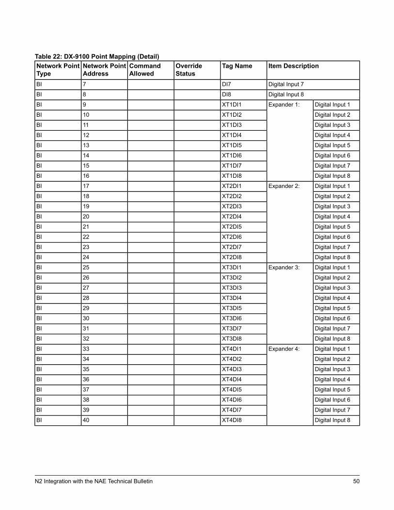
Table 22: DX-9100 Point Mapping (Detail)Item DescriptionTag NameOverride
StatusCommandAllowed
Network PointAddress
Network PointType
Digital Input 7DI77BI
Digital Input 8DI88BI
Digital Input 1Expander 1:XT1DI19BI
Digital Input 2XT1DI210BI
Digital Input 3XT1DI311BI
Digital Input 4XT1DI412BI
Digital Input 5XT1DI513BI
Digital Input 6XT1DI614BI
Digital Input 7XT1DI715BI
Digital Input 8XT1DI816BI
Digital Input 1Expander 2:XT2DI117BI
Digital Input 2XT2DI218BI
Digital Input 3XT2DI319BI
Digital Input 4XT2DI420BI
Digital Input 5XT2DI521BI
Digital Input 6XT2DI622BI
Digital Input 7XT2DI723BI
Digital Input 8XT2DI824BI
Digital Input 1Expander 3:XT3DI125BI
Digital Input 2XT3DI226BI
Digital Input 3XT3DI327BI
Digital Input 4XT3DI428BI
Digital Input 5XT3DI529BI
Digital Input 6XT3DI630BI
Digital Input 7XT3DI731BI
Digital Input 8XT3DI832BI
Digital Input 1Expander 4:XT4DI133BI
Digital Input 2XT4DI234BI
Digital Input 3XT4DI335BI
Digital Input 4XT4DI436BI
Digital Input 5XT4DI537BI
Digital Input 6XT4DI638BI
Digital Input 7XT4DI739BI
Digital Input 8XT4DI840BI
50N2 Integration with the NAE Technical Bulletin
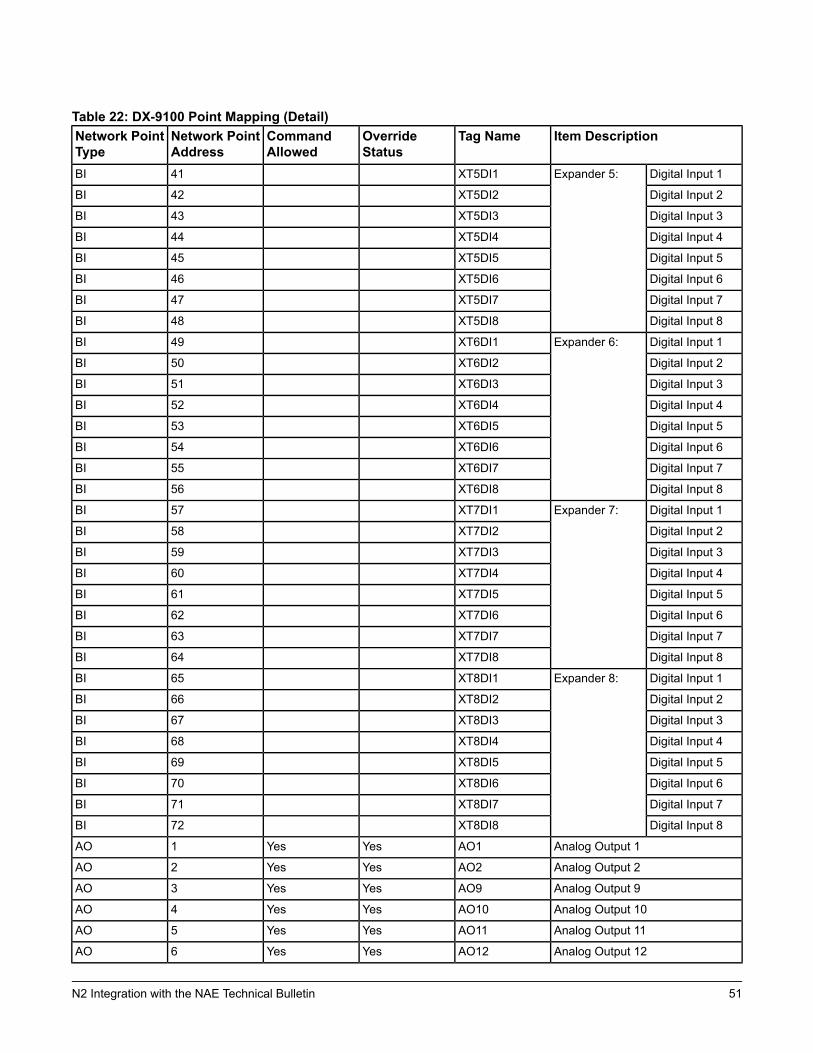
Table 22: DX-9100 Point Mapping (Detail)Item DescriptionTag NameOverride
StatusCommandAllowed
Network PointAddress
Network PointType
Digital Input 1Expander 5:XT5DI141BI
Digital Input 2XT5DI242BI
Digital Input 3XT5DI343BI
Digital Input 4XT5DI444BI
Digital Input 5XT5DI545BI
Digital Input 6XT5DI646BI
Digital Input 7XT5DI747BI
Digital Input 8XT5DI848BI
Digital Input 1Expander 6:XT6DI149BI
Digital Input 2XT6DI250BI
Digital Input 3XT6DI351BI
Digital Input 4XT6DI452BI
Digital Input 5XT6DI553BI
Digital Input 6XT6DI654BI
Digital Input 7XT6DI755BI
Digital Input 8XT6DI856BI
Digital Input 1Expander 7:XT7DI157BI
Digital Input 2XT7DI258BI
Digital Input 3XT7DI359BI
Digital Input 4XT7DI460BI
Digital Input 5XT7DI561BI
Digital Input 6XT7DI662BI
Digital Input 7XT7DI763BI
Digital Input 8XT7DI864BI
Digital Input 1Expander 8:XT8DI165BI
Digital Input 2XT8DI266BI
Digital Input 3XT8DI367BI
Digital Input 4XT8DI468BI
Digital Input 5XT8DI569BI
Digital Input 6XT8DI670BI
Digital Input 7XT8DI771BI
Digital Input 8XT8DI872BI
Analog Output 1AO1YesYes1AO
Analog Output 2AO2YesYes2AO
Analog Output 9AO9YesYes3AO
Analog Output 10AO10YesYes4AO
Analog Output 11AO11YesYes5AO
Analog Output 12AO12YesYes6AO
51N2 Integration with the NAE Technical Bulletin
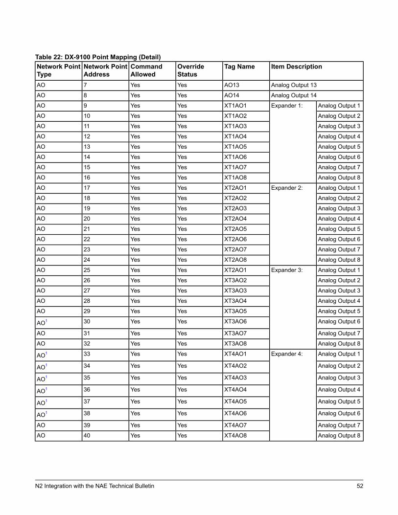
Table 22: DX-9100 Point Mapping (Detail)Item DescriptionTag NameOverride
StatusCommandAllowed
Network PointAddress
Network PointType
Analog Output 13AO13YesYes7AO
Analog Output 14AO14YesYes8AO
Analog Output 1Expander 1:XT1AO1YesYes9AO
Analog Output 2XT1AO2YesYes10AO
Analog Output 3XT1AO3YesYes11AO
Analog Output 4XT1AO4YesYes12AO
Analog Output 5XT1AO5YesYes13AO
Analog Output 6XT1AO6YesYes14AO
Analog Output 7XT1AO7YesYes15AO
Analog Output 8XT1AO8YesYes16AO
Analog Output 1Expander 2:XT2AO1YesYes17AO
Analog Output 2XT2AO2YesYes18AO
Analog Output 3XT2AO3YesYes19AO
Analog Output 4XT2AO4YesYes20AO
Analog Output 5XT2AO5YesYes21AO
Analog Output 6XT2AO6YesYes22AO
Analog Output 7XT2AO7YesYes23AO
Analog Output 8XT2AO8YesYes24AO
Analog Output 1Expander 3:XT2AO1YesYes25AO
Analog Output 2XT3AO2YesYes26AO
Analog Output 3XT3AO3YesYes27AO
Analog Output 4XT3AO4YesYes28AO
Analog Output 5XT3AO5YesYes29AO
Analog Output 6XT3AO6YesYes30AO1
Analog Output 7XT3AO7YesYes31AO
Analog Output 8XT3AO8YesYes32AO
Analog Output 1Expander 4:XT4AO1YesYes33AO1
Analog Output 2XT4AO2YesYes34AO1
Analog Output 3XT4AO3YesYes35AO1
Analog Output 4XT4AO4YesYes36AO1
Analog Output 5XT4AO5YesYes37AO1
Analog Output 6XT4AO6YesYes38AO1
Analog Output 7XT4AO7YesYes39AO
Analog Output 8XT4AO8YesYes40AO
52N2 Integration with the NAE Technical Bulletin
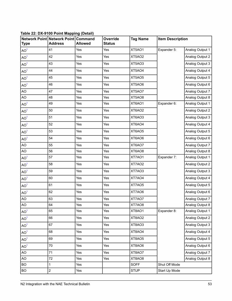
Table 22: DX-9100 Point Mapping (Detail)Item DescriptionTag NameOverride
StatusCommandAllowed
Network PointAddress
Network PointType
Analog Output 1Expander 5:XT5AO1YesYes41AO1
Analog Output 2XT5AO2YesYes42AO1
Analog Output 3XT5AO3YesYes43AO1
Analog Output 4XT5AO4YesYes44AO1
Analog Output 5XT5AO5YesYes45AO1
Analog Output 6XT5AO6YesYes46AO1
Analog Output 7XT5AO7YesYes47AO
Analog Output 8XT5AO8YesYes48AO
Analog Output 1Expander 6:XT6AO1YesYes49AO1
Analog Output 2XT6AO2YesYes50AO1
Analog Output 3XT6AO3YesYes51AO1
Analog Output 4XT6AO4YesYes52AO1
Analog Output 5XT6AO5YesYes53AO1
Analog Output 6XT6AO6YesYes54AO1
Analog Output 7XT6AO7YesYes55AO
Analog Output 8XT6AO8YesYes56AO
Analog Output 1Expander 7:XT7AO1YesYes57AO1
Analog Output 2XT7AO2YesYes58AO1
Analog Output 3XT7AO3YesYes59AO1
Analog Output 4XT7AO4YesYes60AO1
Analog Output 5XT7AO5YesYes61AO1
Analog Output 6XT7AO6YesYes62AO1
Analog Output 7XT7AO7YesYes63AO
Analog Output 8XT7AO8YesYes64AO
Analog Output 1Expander 8:XT8AO1YesYes65AO1
Analog Output 2XT8AO2YesYes66AO1
Analog Output 3XT8AO3YesYes67AO1
Analog Output 4XT8AO4YesYes68AO1
Analog Output 5XT8AO5YesYes69AO1
Analog Output 6XT8AO6YesYes70AO1
Analog Output 7XT8AO7YesYes71AO
Analog Output 8XT8AO8YesYes72AO
Shut Off ModeSOFFYes1BO
Start Up ModeSTUPYes2BO
53N2 Integration with the NAE Technical Bulletin
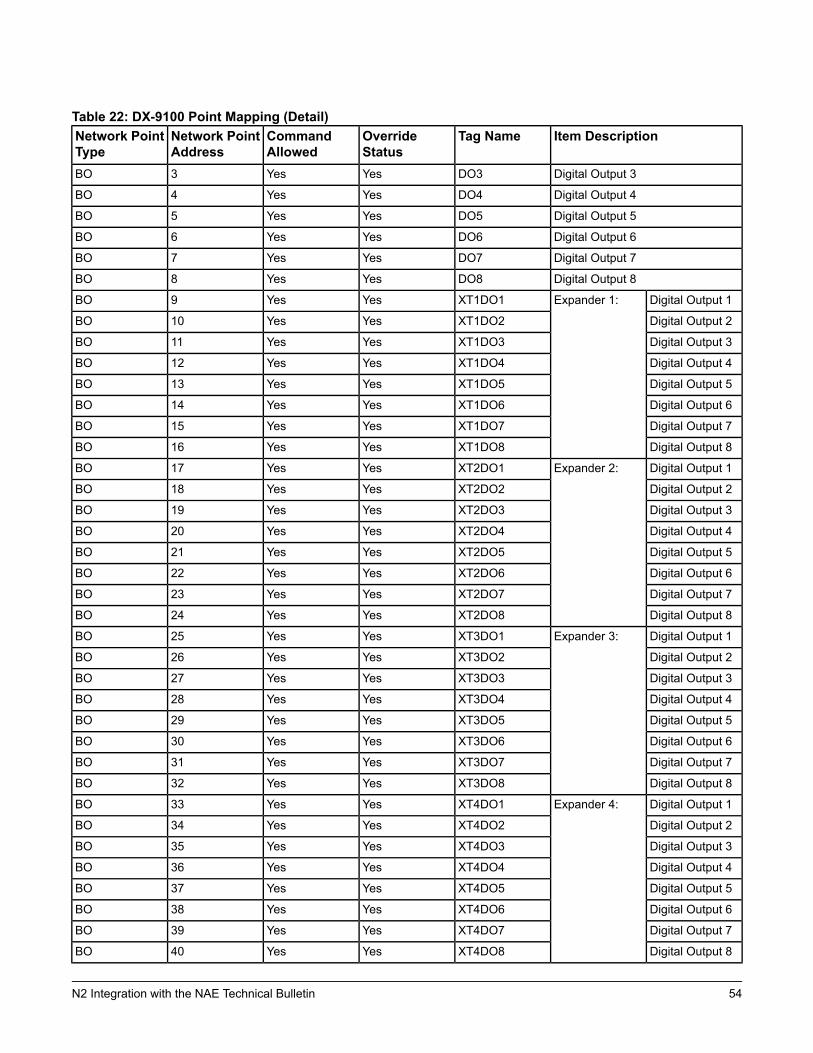
Table 22: DX-9100 Point Mapping (Detail)Item DescriptionTag NameOverride
StatusCommandAllowed
Network PointAddress
Network PointType
Digital Output 3DO3YesYes3BO
Digital Output 4DO4YesYes4BO
Digital Output 5DO5YesYes5BO
Digital Output 6DO6YesYes6BO
Digital Output 7DO7YesYes7BO
Digital Output 8DO8YesYes8BO
Digital Output 1Expander 1:XT1DO1YesYes9BO
Digital Output 2XT1DO2YesYes10BO
Digital Output 3XT1DO3YesYes11BO
Digital Output 4XT1DO4YesYes12BO
Digital Output 5XT1DO5YesYes13BO
Digital Output 6XT1DO6YesYes14BO
Digital Output 7XT1DO7YesYes15BO
Digital Output 8XT1DO8YesYes16BO
Digital Output 1Expander 2:XT2DO1YesYes17BO
Digital Output 2XT2DO2YesYes18BO
Digital Output 3XT2DO3YesYes19BO
Digital Output 4XT2DO4YesYes20BO
Digital Output 5XT2DO5YesYes21BO
Digital Output 6XT2DO6YesYes22BO
Digital Output 7XT2DO7YesYes23BO
Digital Output 8XT2DO8YesYes24BO
Digital Output 1Expander 3:XT3DO1YesYes25BO
Digital Output 2XT3DO2YesYes26BO
Digital Output 3XT3DO3YesYes27BO
Digital Output 4XT3DO4YesYes28BO
Digital Output 5XT3DO5YesYes29BO
Digital Output 6XT3DO6YesYes30BO
Digital Output 7XT3DO7YesYes31BO
Digital Output 8XT3DO8YesYes32BO
Digital Output 1Expander 4:XT4DO1YesYes33BO
Digital Output 2XT4DO2YesYes34BO
Digital Output 3XT4DO3YesYes35BO
Digital Output 4XT4DO4YesYes36BO
Digital Output 5XT4DO5YesYes37BO
Digital Output 6XT4DO6YesYes38BO
Digital Output 7XT4DO7YesYes39BO
Digital Output 8XT4DO8YesYes40BO
54N2 Integration with the NAE Technical Bulletin
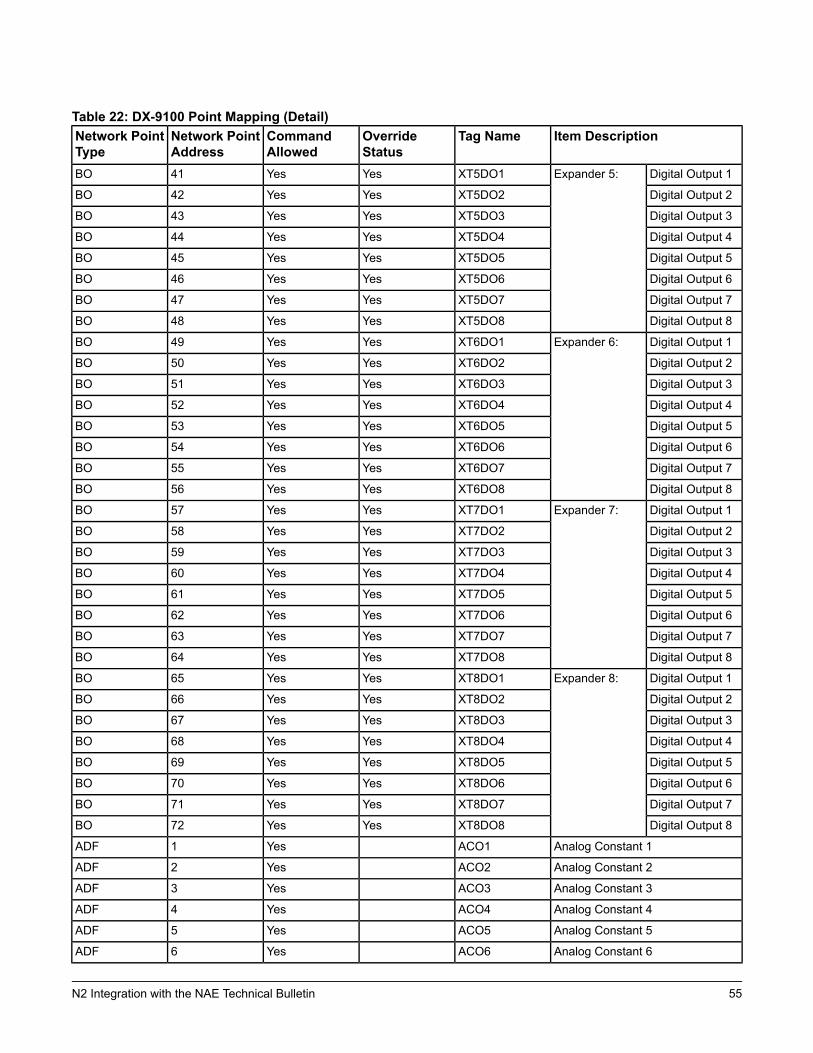
Table 22: DX-9100 Point Mapping (Detail)Item DescriptionTag NameOverride
StatusCommandAllowed
Network PointAddress
Network PointType
Digital Output 1Expander 5:XT5DO1YesYes41BO
Digital Output 2XT5DO2YesYes42BO
Digital Output 3XT5DO3YesYes43BO
Digital Output 4XT5DO4YesYes44BO
Digital Output 5XT5DO5YesYes45BO
Digital Output 6XT5DO6YesYes46BO
Digital Output 7XT5DO7YesYes47BO
Digital Output 8XT5DO8YesYes48BO
Digital Output 1Expander 6:XT6DO1YesYes49BO
Digital Output 2XT6DO2YesYes50BO
Digital Output 3XT6DO3YesYes51BO
Digital Output 4XT6DO4YesYes52BO
Digital Output 5XT6DO5YesYes53BO
Digital Output 6XT6DO6YesYes54BO
Digital Output 7XT6DO7YesYes55BO
Digital Output 8XT6DO8YesYes56BO
Digital Output 1Expander 7:XT7DO1YesYes57BO
Digital Output 2XT7DO2YesYes58BO
Digital Output 3XT7DO3YesYes59BO
Digital Output 4XT7DO4YesYes60BO
Digital Output 5XT7DO5YesYes61BO
Digital Output 6XT7DO6YesYes62BO
Digital Output 7XT7DO7YesYes63BO
Digital Output 8XT7DO8YesYes64BO
Digital Output 1Expander 8:XT8DO1YesYes65BO
Digital Output 2XT8DO2YesYes66BO
Digital Output 3XT8DO3YesYes67BO
Digital Output 4XT8DO4YesYes68BO
Digital Output 5XT8DO5YesYes69BO
Digital Output 6XT8DO6YesYes70BO
Digital Output 7XT8DO7YesYes71BO
Digital Output 8XT8DO8YesYes72BO
Analog Constant 1ACO1Yes1ADF
Analog Constant 2ACO2Yes2ADF
Analog Constant 3ACO3Yes3ADF
Analog Constant 4ACO4Yes4ADF
Analog Constant 5ACO5Yes5ADF
Analog Constant 6ACO6Yes6ADF
55N2 Integration with the NAE Technical Bulletin
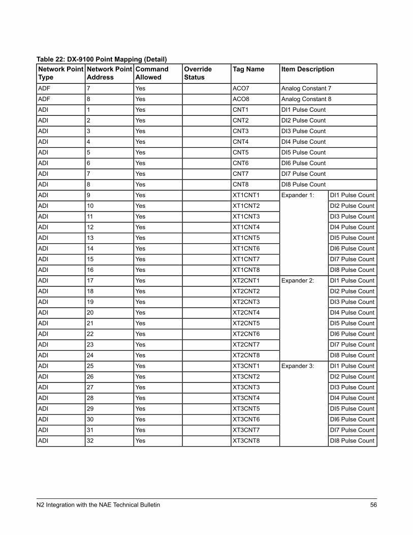
Table 22: DX-9100 Point Mapping (Detail)Item DescriptionTag NameOverride
StatusCommandAllowed
Network PointAddress
Network PointType
Analog Constant 7ACO7Yes7ADF
Analog Constant 8ACO8Yes8ADF
DI1 Pulse CountCNT1Yes1ADI
DI2 Pulse CountCNT2Yes2ADI
DI3 Pulse CountCNT3Yes3ADI
DI4 Pulse CountCNT4Yes4ADI
DI5 Pulse CountCNT5Yes5ADI
DI6 Pulse CountCNT6Yes6ADI
DI7 Pulse CountCNT7Yes7ADI
DI8 Pulse CountCNT8Yes8ADI
DI1 Pulse CountExpander 1:XT1CNT1Yes9ADI
DI2 Pulse CountXT1CNT2Yes10ADI
DI3 Pulse CountXT1CNT3Yes11ADI
DI4 Pulse CountXT1CNT4Yes12ADI
DI5 Pulse CountXT1CNT5Yes13ADI
DI6 Pulse CountXT1CNT6Yes14ADI
DI7 Pulse CountXT1CNT7Yes15ADI
DI8 Pulse CountXT1CNT8Yes16ADI
DI1 Pulse CountExpander 2:XT2CNT1Yes17ADI
DI2 Pulse CountXT2CNT2Yes18ADI
DI3 Pulse CountXT2CNT3Yes19ADI
DI4 Pulse CountXT2CNT4Yes20ADI
DI5 Pulse CountXT2CNT5Yes21ADI
DI6 Pulse CountXT2CNT6Yes22ADI
DI7 Pulse CountXT2CNT7Yes23ADI
DI8 Pulse CountXT2CNT8Yes24ADI
DI1 Pulse CountExpander 3:XT3CNT1Yes25ADI
DI2 Pulse CountXT3CNT2Yes26ADI
DI3 Pulse CountXT3CNT3Yes27ADI
DI4 Pulse CountXT3CNT4Yes28ADI
DI5 Pulse CountXT3CNT5Yes29ADI
DI6 Pulse CountXT3CNT6Yes30ADI
DI7 Pulse CountXT3CNT7Yes31ADI
DI8 Pulse CountXT3CNT8Yes32ADI
56N2 Integration with the NAE Technical Bulletin
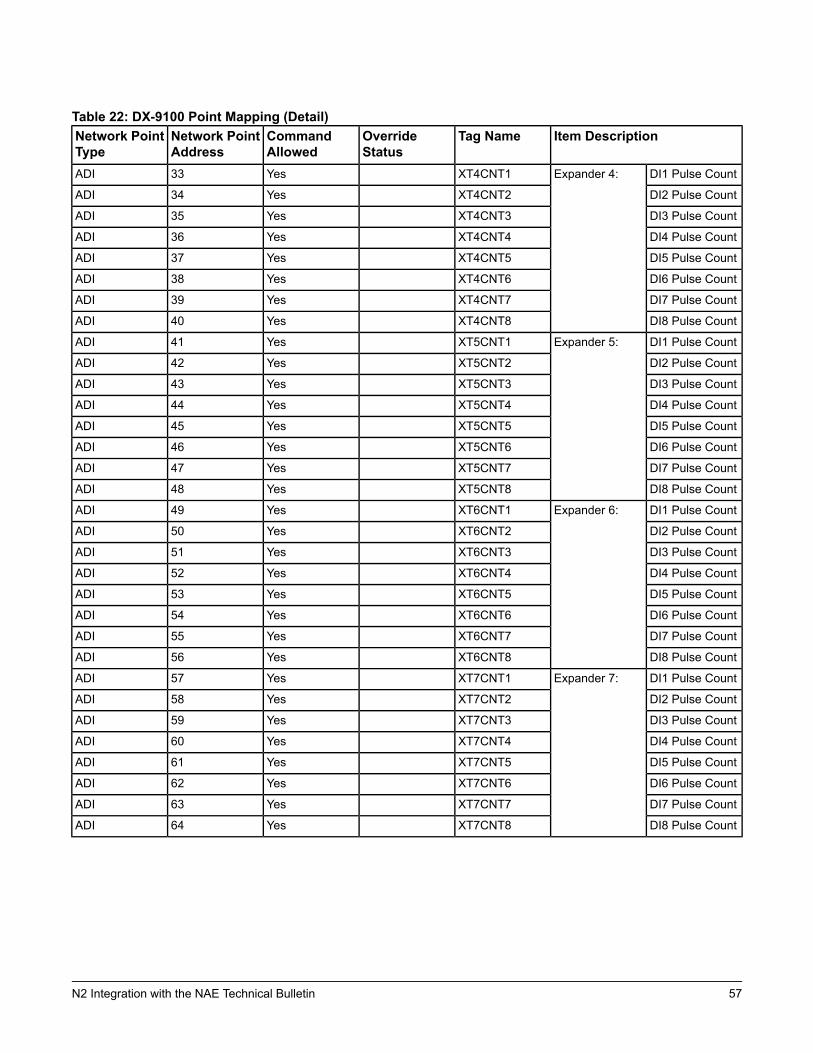
Table 22: DX-9100 Point Mapping (Detail)Item DescriptionTag NameOverride
StatusCommandAllowed
Network PointAddress
Network PointType
DI1 Pulse CountExpander 4:XT4CNT1Yes33ADI
DI2 Pulse CountXT4CNT2Yes34ADI
DI3 Pulse CountXT4CNT3Yes35ADI
DI4 Pulse CountXT4CNT4Yes36ADI
DI5 Pulse CountXT4CNT5Yes37ADI
DI6 Pulse CountXT4CNT6Yes38ADI
DI7 Pulse CountXT4CNT7Yes39ADI
DI8 Pulse CountXT4CNT8Yes40ADI
DI1 Pulse CountExpander 5:XT5CNT1Yes41ADI
DI2 Pulse CountXT5CNT2Yes42ADI
DI3 Pulse CountXT5CNT3Yes43ADI
DI4 Pulse CountXT5CNT4Yes44ADI
DI5 Pulse CountXT5CNT5Yes45ADI
DI6 Pulse CountXT5CNT6Yes46ADI
DI7 Pulse CountXT5CNT7Yes47ADI
DI8 Pulse CountXT5CNT8Yes48ADI
DI1 Pulse CountExpander 6:XT6CNT1Yes49ADI
DI2 Pulse CountXT6CNT2Yes50ADI
DI3 Pulse CountXT6CNT3Yes51ADI
DI4 Pulse CountXT6CNT4Yes52ADI
DI5 Pulse CountXT6CNT5Yes53ADI
DI6 Pulse CountXT6CNT6Yes54ADI
DI7 Pulse CountXT6CNT7Yes55ADI
DI8 Pulse CountXT6CNT8Yes56ADI
DI1 Pulse CountExpander 7:XT7CNT1Yes57ADI
DI2 Pulse CountXT7CNT2Yes58ADI
DI3 Pulse CountXT7CNT3Yes59ADI
DI4 Pulse CountXT7CNT4Yes60ADI
DI5 Pulse CountXT7CNT5Yes61ADI
DI6 Pulse CountXT7CNT6Yes62ADI
DI7 Pulse CountXT7CNT7Yes63ADI
DI8 Pulse CountXT7CNT8Yes64ADI
57N2 Integration with the NAE Technical Bulletin
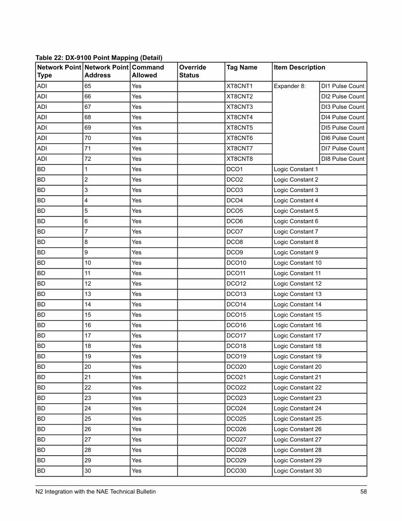
Table 22: DX-9100 Point Mapping (Detail)Item DescriptionTag NameOverride
StatusCommandAllowed
Network PointAddress
Network PointType
DI1 Pulse CountExpander 8:XT8CNT1Yes65ADI
DI2 Pulse CountXT8CNT2Yes66ADI
DI3 Pulse CountXT8CNT3Yes67ADI
DI4 Pulse CountXT8CNT4Yes68ADI
DI5 Pulse CountXT8CNT5Yes69ADI
DI6 Pulse CountXT8CNT6Yes70ADI
DI7 Pulse CountXT8CNT7Yes71ADI
DI8 Pulse CountXT8CNT8Yes72ADI
Logic Constant 1DCO1Yes1BD
Logic Constant 2DCO2Yes2BD
Logic Constant 3DCO3Yes3BD
Logic Constant 4DCO4Yes4BD
Logic Constant 5DCO5Yes5BD
Logic Constant 6DCO6Yes6BD
Logic Constant 7DCO7Yes7BD
Logic Constant 8DCO8Yes8BD
Logic Constant 9DCO9Yes9BD
Logic Constant 10DCO10Yes10BD
Logic Constant 11DCO11Yes11BD
Logic Constant 12DCO12Yes12BD
Logic Constant 13DCO13Yes13BD
Logic Constant 14DCO14Yes14BD
Logic Constant 15DCO15Yes15BD
Logic Constant 16DCO16Yes16BD
Logic Constant 17DCO17Yes17BD
Logic Constant 18DCO18Yes18BD
Logic Constant 19DCO19Yes19BD
Logic Constant 20DCO20Yes20BD
Logic Constant 21DCO21Yes21BD
Logic Constant 22DCO22Yes22BD
Logic Constant 23DCO23Yes23BD
Logic Constant 24DCO24Yes24BD
Logic Constant 25DCO25Yes25BD
Logic Constant 26DCO26Yes26BD
Logic Constant 27DCO27Yes27BD
Logic Constant 28DCO28Yes28BD
Logic Constant 29DCO29Yes29BD
Logic Constant 30DCO30Yes30BD
58N2 Integration with the NAE Technical Bulletin
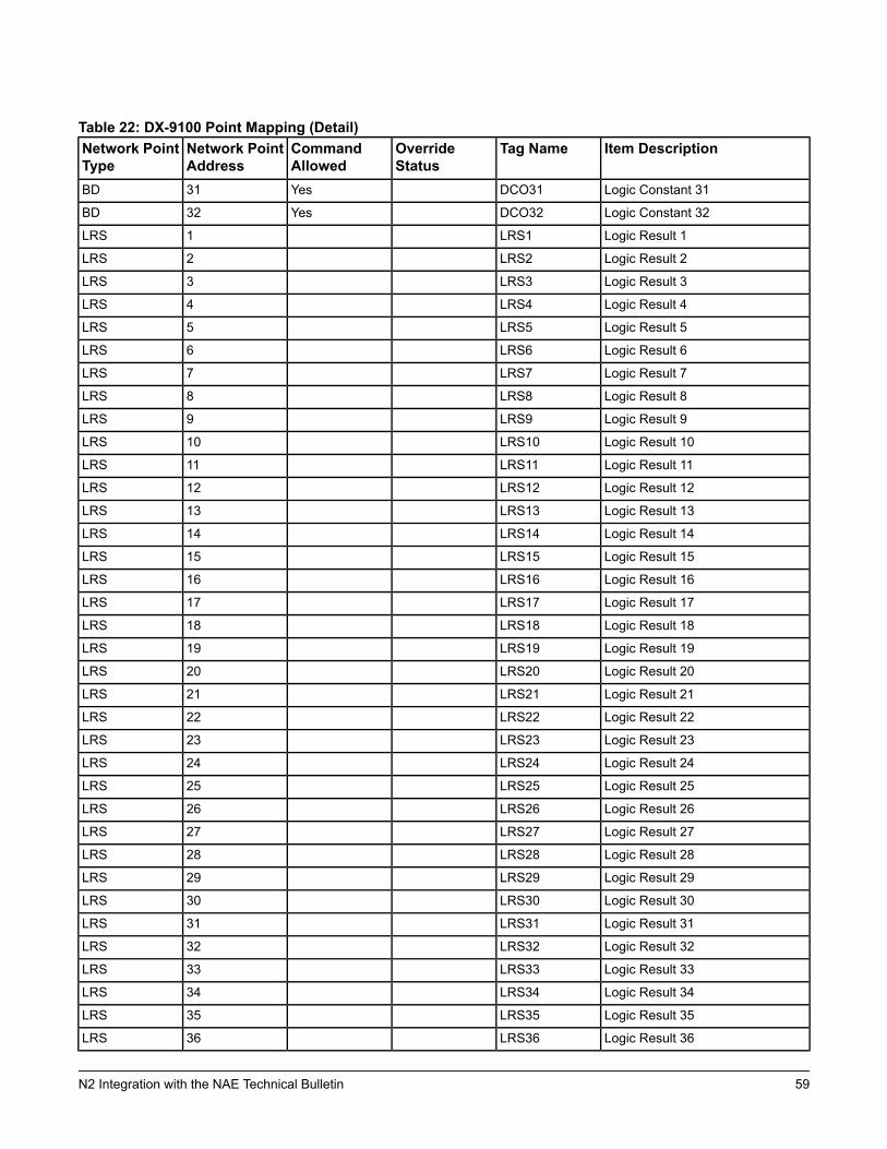
Table 22: DX-9100 Point Mapping (Detail)Item DescriptionTag NameOverride
StatusCommandAllowed
Network PointAddress
Network PointType
Logic Constant 31DCO31Yes31BD
Logic Constant 32DCO32Yes32BD
Logic Result 1LRS11LRS
Logic Result 2LRS22LRS
Logic Result 3LRS33LRS
Logic Result 4LRS44LRS
Logic Result 5LRS55LRS
Logic Result 6LRS66LRS
Logic Result 7LRS77LRS
Logic Result 8LRS88LRS
Logic Result 9LRS99LRS
Logic Result 10LRS1010LRS
Logic Result 11LRS1111LRS
Logic Result 12LRS1212LRS
Logic Result 13LRS1313LRS
Logic Result 14LRS1414LRS
Logic Result 15LRS1515LRS
Logic Result 16LRS1616LRS
Logic Result 17LRS1717LRS
Logic Result 18LRS1818LRS
Logic Result 19LRS1919LRS
Logic Result 20LRS2020LRS
Logic Result 21LRS2121LRS
Logic Result 22LRS2222LRS
Logic Result 23LRS2323LRS
Logic Result 24LRS2424LRS
Logic Result 25LRS2525LRS
Logic Result 26LRS2626LRS
Logic Result 27LRS2727LRS
Logic Result 28LRS2828LRS
Logic Result 29LRS2929LRS
Logic Result 30LRS3030LRS
Logic Result 31LRS3131LRS
Logic Result 32LRS3232LRS
Logic Result 33LRS3333LRS
Logic Result 34LRS3434LRS
Logic Result 35LRS3535LRS
Logic Result 36LRS3636LRS
59N2 Integration with the NAE Technical Bulletin
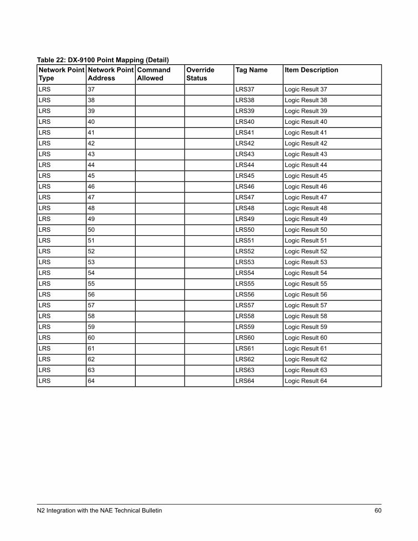
Table 22: DX-9100 Point Mapping (Detail)Item DescriptionTag NameOverride
StatusCommandAllowed
Network PointAddress
Network PointType
Logic Result 37LRS3737LRS
Logic Result 38LRS3838LRS
Logic Result 39LRS3939LRS
Logic Result 40LRS4040LRS
Logic Result 41LRS4141LRS
Logic Result 42LRS4242LRS
Logic Result 43LRS4343LRS
Logic Result 44LRS4444LRS
Logic Result 45LRS4545LRS
Logic Result 46LRS4646LRS
Logic Result 47LRS4747LRS
Logic Result 48LRS4848LRS
Logic Result 49LRS4949LRS
Logic Result 50LRS5050LRS
Logic Result 51LRS5151LRS
Logic Result 52LRS5252LRS
Logic Result 53LRS5353LRS
Logic Result 54LRS5454LRS
Logic Result 55LRS5555LRS
Logic Result 56LRS5656LRS
Logic Result 57LRS5757LRS
Logic Result 58LRS5858LRS
Logic Result 59LRS5959LRS
Logic Result 60LRS6060LRS
Logic Result 61LRS6161LRS
Logic Result 62LRS6262LRS
Logic Result 63LRS6363LRS
Logic Result 64LRS6464LRS
60N2 Integration with the NAE Technical Bulletin
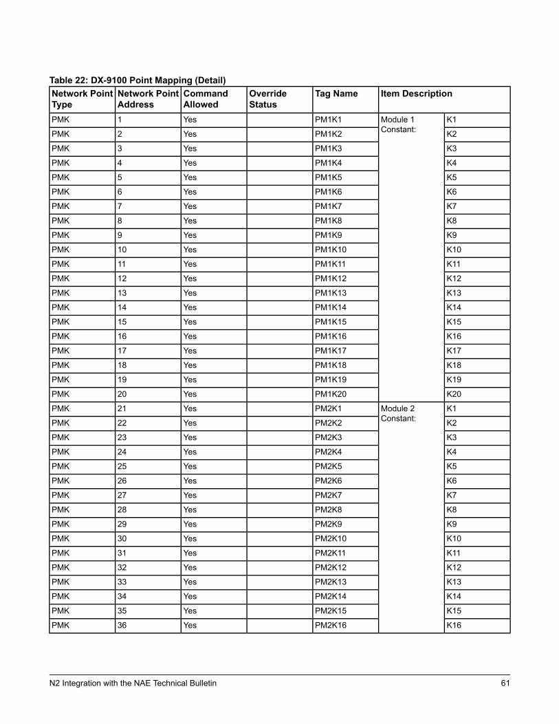
Table 22: DX-9100 Point Mapping (Detail)Item DescriptionTag NameOverride
StatusCommandAllowed
Network PointAddress
Network PointType
K1Module 1Constant:
PM1K1Yes1PMK
K2PM1K2Yes2PMK
K3PM1K3Yes3PMK
K4PM1K4Yes4PMK
K5PM1K5Yes5PMK
K6PM1K6Yes6PMK
K7PM1K7Yes7PMK
K8PM1K8Yes8PMK
K9PM1K9Yes9PMK
K10PM1K10Yes10PMK
K11PM1K11Yes11PMK
K12PM1K12Yes12PMK
K13PM1K13Yes13PMK
K14PM1K14Yes14PMK
K15PM1K15Yes15PMK
K16PM1K16Yes16PMK
K17PM1K17Yes17PMK
K18PM1K18Yes18PMK
K19PM1K19Yes19PMK
K20PM1K20Yes20PMK
K1Module 2Constant:
PM2K1Yes21PMK
K2PM2K2Yes22PMK
K3PM2K3Yes23PMK
K4PM2K4Yes24PMK
K5PM2K5Yes25PMK
K6PM2K6Yes26PMK
K7PM2K7Yes27PMK
K8PM2K8Yes28PMK
K9PM2K9Yes29PMK
K10PM2K10Yes30PMK
K11PM2K11Yes31PMK
K12PM2K12Yes32PMK
K13PM2K13Yes33PMK
K14PM2K14Yes34PMK
K15PM2K15Yes35PMK
K16PM2K16Yes36PMK
61N2 Integration with the NAE Technical Bulletin
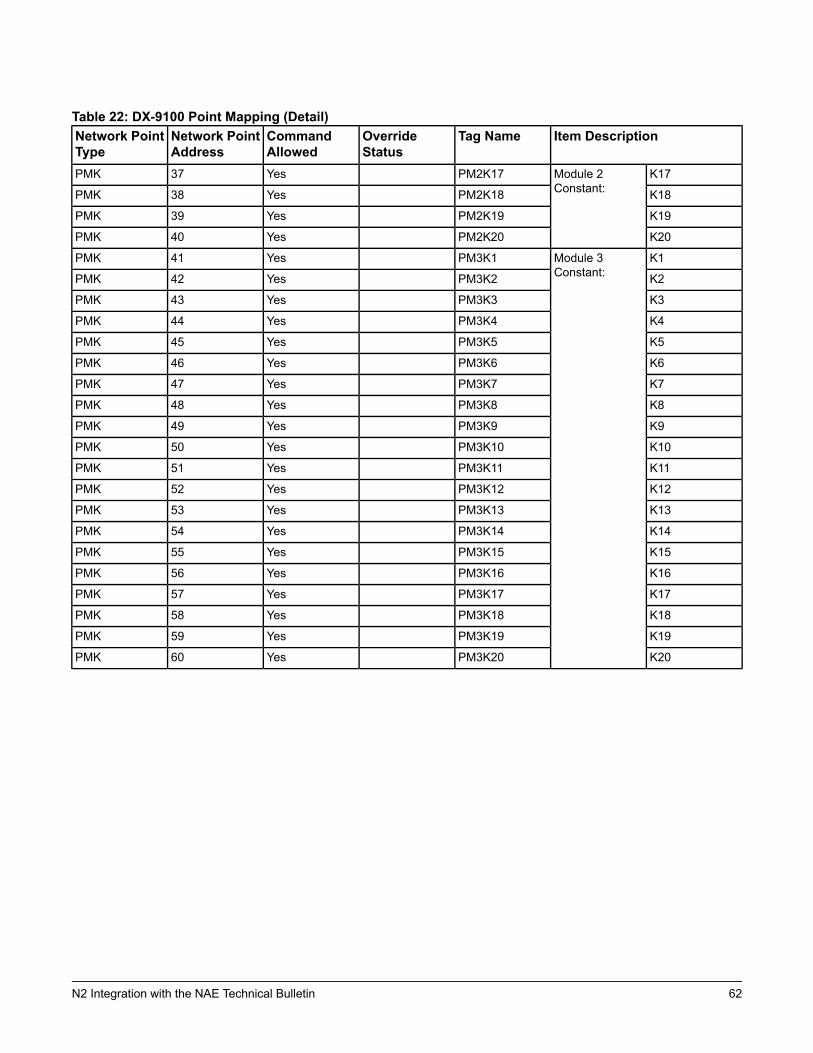
Table 22: DX-9100 Point Mapping (Detail)Item DescriptionTag NameOverride
StatusCommandAllowed
Network PointAddress
Network PointType
K17Module 2Constant:
PM2K17Yes37PMK
K18PM2K18Yes38PMK
K19PM2K19Yes39PMK
K20PM2K20Yes40PMK
K1Module 3Constant:
PM3K1Yes41PMK
K2PM3K2Yes42PMK
K3PM3K3Yes43PMK
K4PM3K4Yes44PMK
K5PM3K5Yes45PMK
K6PM3K6Yes46PMK
K7PM3K7Yes47PMK
K8PM3K8Yes48PMK
K9PM3K9Yes49PMK
K10PM3K10Yes50PMK
K11PM3K11Yes51PMK
K12PM3K12Yes52PMK
K13PM3K13Yes53PMK
K14PM3K14Yes54PMK
K15PM3K15Yes55PMK
K16PM3K16Yes56PMK
K17PM3K17Yes57PMK
K18PM3K18Yes58PMK
K19PM3K19Yes59PMK
K20PM3K20Yes60PMK
62N2 Integration with the NAE Technical Bulletin
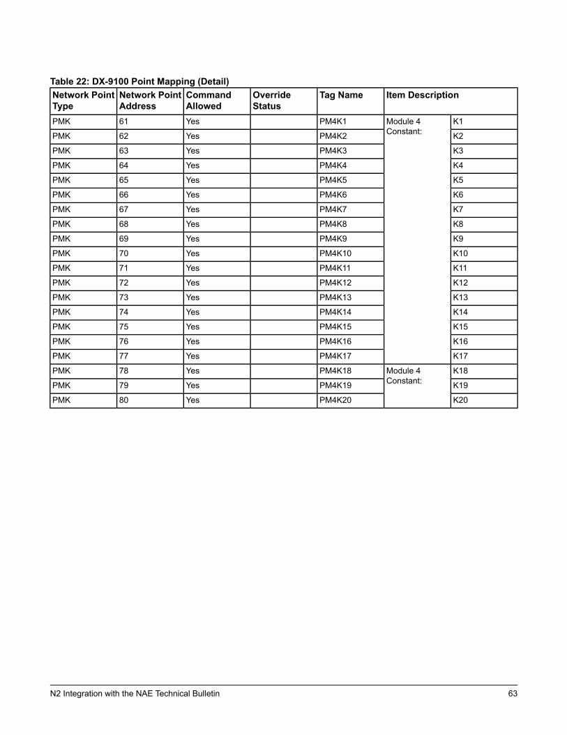
Table 22: DX-9100 Point Mapping (Detail)Item DescriptionTag NameOverride
StatusCommandAllowed
Network PointAddress
Network PointType
K1Module 4Constant:
PM4K1Yes61PMK
K2PM4K2Yes62PMK
K3PM4K3Yes63PMK
K4PM4K4Yes64PMK
K5PM4K5Yes65PMK
K6PM4K6Yes66PMK
K7PM4K7Yes67PMK
K8PM4K8Yes68PMK
K9PM4K9Yes69PMK
K10PM4K10Yes70PMK
K11PM4K11Yes71PMK
K12PM4K12Yes72PMK
K13PM4K13Yes73PMK
K14PM4K14Yes74PMK
K15PM4K15Yes75PMK
K16PM4K16Yes76PMK
K17PM4K17Yes77PMK
K18Module 4Constant:
PM4K18Yes78PMK
K19PM4K19Yes79PMK
K20PM4K20Yes80PMK
63N2 Integration with the NAE Technical Bulletin
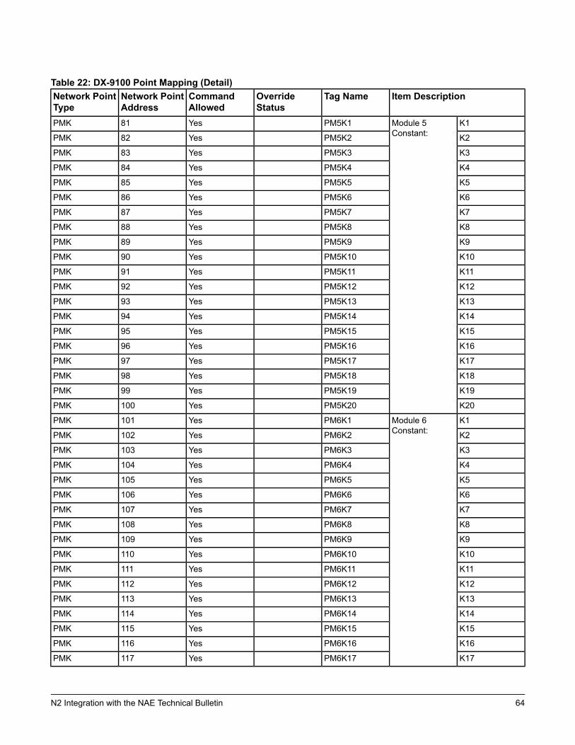
Table 22: DX-9100 Point Mapping (Detail)Item DescriptionTag NameOverride
StatusCommandAllowed
Network PointAddress
Network PointType
K1Module 5Constant:
PM5K1Yes81PMK
K2PM5K2Yes82PMK
K3PM5K3Yes83PMK
K4PM5K4Yes84PMK
K5PM5K5Yes85PMK
K6PM5K6Yes86PMK
K7PM5K7Yes87PMK
K8PM5K8Yes88PMK
K9PM5K9Yes89PMK
K10PM5K10Yes90PMK
K11PM5K11Yes91PMK
K12PM5K12Yes92PMK
K13PM5K13Yes93PMK
K14PM5K14Yes94PMK
K15PM5K15Yes95PMK
K16PM5K16Yes96PMK
K17PM5K17Yes97PMK
K18PM5K18Yes98PMK
K19PM5K19Yes99PMK
K20PM5K20Yes100PMK
K1Module 6Constant:
PM6K1Yes101PMK
K2PM6K2Yes102PMK
K3PM6K3Yes103PMK
K4PM6K4Yes104PMK
K5PM6K5Yes105PMK
K6PM6K6Yes106PMK
K7PM6K7Yes107PMK
K8PM6K8Yes108PMK
K9PM6K9Yes109PMK
K10PM6K10Yes110PMK
K11PM6K11Yes111PMK
K12PM6K12Yes112PMK
K13PM6K13Yes113PMK
K14PM6K14Yes114PMK
K15PM6K15Yes115PMK
K16PM6K16Yes116PMK
K17PM6K17Yes117PMK
64N2 Integration with the NAE Technical Bulletin
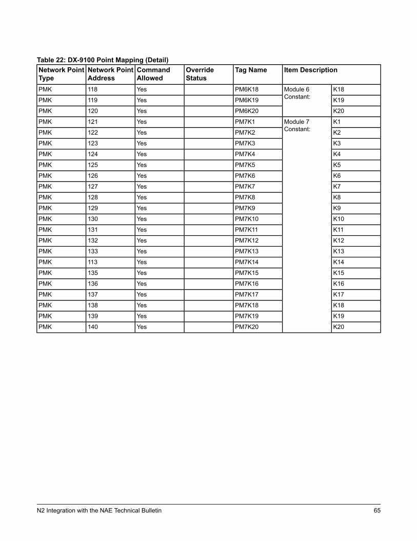
Table 22: DX-9100 Point Mapping (Detail)Item DescriptionTag NameOverride
StatusCommandAllowed
Network PointAddress
Network PointType
K18Module 6Constant:
PM6K18Yes118PMK
K19PM6K19Yes119PMK
K20PM6K20Yes120PMK
K1Module 7Constant:
PM7K1Yes121PMK
K2PM7K2Yes122PMK
K3PM7K3Yes123PMK
K4PM7K4Yes124PMK
K5PM7K5Yes125PMK
K6PM7K6Yes126PMK
K7PM7K7Yes127PMK
K8PM7K8Yes128PMK
K9PM7K9Yes129PMK
K10PM7K10Yes130PMK
K11PM7K11Yes131PMK
K12PM7K12Yes132PMK
K13PM7K13Yes133PMK
K14PM7K14Yes113PMK
K15PM7K15Yes135PMK
K16PM7K16Yes136PMK
K17PM7K17Yes137PMK
K18PM7K18Yes138PMK
K19PM7K19Yes139PMK
K20PM7K20Yes140PMK
65N2 Integration with the NAE Technical Bulletin
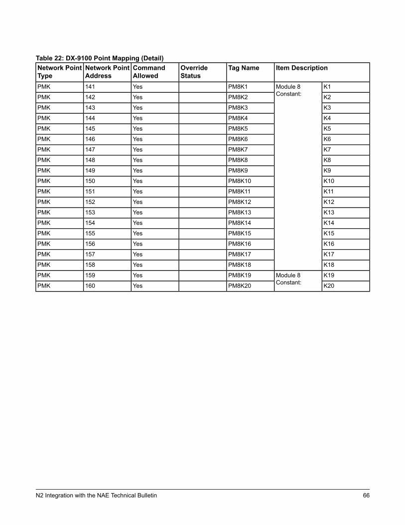
Table 22: DX-9100 Point Mapping (Detail)Item DescriptionTag NameOverride
StatusCommandAllowed
Network PointAddress
Network PointType
K1Module 8Constant:
PM8K1Yes141PMK
K2PM8K2Yes142PMK
K3PM8K3Yes143PMK
K4PM8K4Yes144PMK
K5PM8K5Yes145PMK
K6PM8K6Yes146PMK
K7PM8K7Yes147PMK
K8PM8K8Yes148PMK
K9PM8K9Yes149PMK
K10PM8K10Yes150PMK
K11PM8K11Yes151PMK
K12PM8K12Yes152PMK
K13PM8K13Yes153PMK
K14PM8K14Yes154PMK
K15PM8K15Yes155PMK
K16PM8K16Yes156PMK
K17PM8K17Yes157PMK
K18PM8K18Yes158PMK
K19Module 8Constant:
PM8K19Yes159PMK
K20PM8K20Yes160PMK
66N2 Integration with the NAE Technical Bulletin
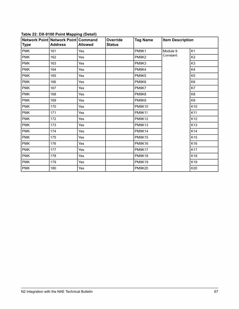
Table 22: DX-9100 Point Mapping (Detail)Item DescriptionTag NameOverride
StatusCommandAllowed
Network PointAddress
Network PointType
K1Module 9Constant:
PM9K1Yes161PMK
K2PM9K2Yes162PMK
K3PM9K3Yes163PMK
K4PM9K4Yes164PMK
K5PM9K5Yes165PMK
K6PM9K6Yes166PMK
K7PM9K7Yes167PMK
K8PM9K8Yes168PMK
K9PM9K9Yes169PMK
K10PM9K10Yes170PMK
K11PM9K11Yes171PMK
K12PM9K12Yes172PMK
K13PM9K13Yes173PMK
K14PM9K14Yes174PMK
K15PM9K15Yes175PMK
K16PM9K16Yes176PMK
K17PM9K17Yes177PMK
K18PM9K18Yes178PMK
K19PM9K19Yes179PMK
K20PM9K20Yes180PMK
67N2 Integration with the NAE Technical Bulletin
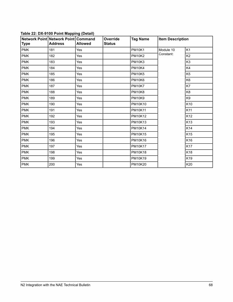
Table 22: DX-9100 Point Mapping (Detail)Item DescriptionTag NameOverride
StatusCommandAllowed
Network PointAddress
Network PointType
K1Module 10Constant:
PM10K1Yes181PMK
K2PM10K2Yes182PMK
K3PM10K3Yes183PMK
K4PM10K4Yes184PMK
K5PM10K5Yes185PMK
K6PM10K6Yes186PMK
K7PM10K7Yes187PMK
K8PM10K8Yes188PMK
K9PM10K9Yes189PMK
K10PM10K10Yes190PMK
K11PM10K11Yes191PMK
K12PM10K12Yes192PMK
K13PM10K13Yes193PMK
K14PM10K14Yes194PMK
K15PM10K15Yes195PMK
K16PM10K16Yes196PMK
K17PM10K17Yes197PMK
K18PM10K18Yes198PMK
K19PM10K19Yes199PMK
K20PM10K20Yes200PMK
68N2 Integration with the NAE Technical Bulletin
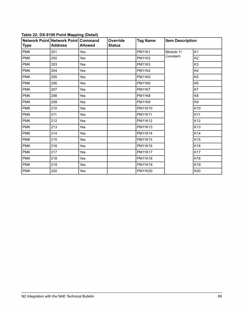
Table 22: DX-9100 Point Mapping (Detail)Item DescriptionTag NameOverride
StatusCommandAllowed
Network PointAddress
Network PointType
K1Module 11Constant:
PM11K1Yes201PMK
K2PM11K2Yes202PMK
K3PM11K3Yes203PMK
K4PM11K4Yes204PMK
K5PM11K5Yes205PMK
K6PM11K6Yes206PMK
K7PM11K7Yes207PMK
K8PM11K8Yes208PMK
K9PM11K9Yes209PMK
K10PM11K10Yes210PMK
K11PM11K11Yes211PMK
K12PM11K12Yes212PMK
K13PM11K13Yes213PMK
K14PM11K14Yes214PMK
K15PM11K15Yes215PMK
K16PM11K16Yes216PMK
K17PM11K17Yes217PMK
K18PM11K18Yes218PMK
K19PM11K19Yes219PMK
K20PM11K20Yes220PMK
69N2 Integration with the NAE Technical Bulletin

Table 22: DX-9100 Point Mapping (Detail)Item DescriptionTag NameOverride
StatusCommandAllowed
Network PointAddress
Network PointType
K1Module 12Constant:
PM12K1Yes221PMK
K2PM12K2Yes222PMK
K3PM12K3Yes223PMK
K4PM12K4Yes224PMK
K5PM12K5Yes225PMK
K6PM12K6Yes226PMK
K7PM12K7Yes227PMK
K8PM12K8Yes228PMK
K9PM12K9Yes229PMK
K10PM12K10Yes230PMK
K11PM12K11Yes231PMK
K12PM12K12Yes232PMK
K13PM12K13Yes233PMK
K14PM12K14Yes234PMK
K15PM12K15Yes235PMK
K16PM12K16Yes236PMK
K17PM12K17Yes237PMK
K18PM12K18Yes238PMK
K19PM12K19Yes239PMK
K20PM12K20Yes240PMK
Channel 1Module 1 Output:PM1OU1YesYes1PMO
Channel 2PM1OU2YesYes2PMO
Channel 3PM1OU3YesYes3PMO
Channel 4PM1OU4YesYes4PMO
Channel 5PM1OU5YesYes5PMO
Channel 6PM1OU6YesYes6PMO
Channel 7PM1OU7YesYes7PMO
Channel 8PM1OU8YesYes8PMO
Channel 1Module 2 Output:PM2OU1YesYes9PMO
Channel 2PM2OU2YesYes10PMO
Channel 3PM2OU3YesYes11PMO
Channel 4PM2OU4YesYes12PMO
Channel 5PM2OU5YesYes13PMO
Channel 6PM2OU6YesYes14PMO
Channel 7PM2OU7YesYes15PMO
Channel 8PM2OU8YesYes16PMO
70N2 Integration with the NAE Technical Bulletin

Table 22: DX-9100 Point Mapping (Detail)Item DescriptionTag NameOverride
StatusCommandAllowed
Network PointAddress
Network PointType
Channel 1Module 3 Output:PM3OU1YesYes17PMO
Channel 2PM3OU2YesYes18PMO
Channel 3PM3OU3YesYes19PMO
Channel 4PM3OU4YesYes20PMO
Channel 5PM3OU5YesYes21PMO
Channel 6PM3OU6YesYes22PMO
Channel 7PM3OU7YesYes23PMO
Channel 8PM3OU8YesYes24PMO
Channel 1Module 4 Output:PM4OU1YesYes25PMO
Channel 2PM4OU2YesYes26PMO
Channel 3PM4OU3YesYes27PMO
Channel 4PM4OU4YesYes28PMO
Channel 5PM4OU5YesYes29PMO
Channel 6PM4OU6YesYes30PMO
Channel 7PM4OU7YesYes31PMO
Channel 8PM4OU8YesYes32PMO
Channel 1Module 5 Output:PM5OU1YesYes33PMO
Channel 2PM5OU2YesYes34PMO
Channel 3PM5OU3YesYes35PMO
Channel 4PM5OU4YesYes36PMO
Channel 5PM5OU5YesYes37PMO
Channel 6PM5OU6YesYes38PMO
Channel 7PM5OU7YesYes39PMO
Channel 8PM5OU8YesYes40PMO
Channel 1Module 6 Output:PM6OU1YesYes41PMO
Channel 2PM6OU2YesYes42PMO
Channel 3PM6OU3YesYes43PMO
Channel 4PM6OU4YesYes44PMO
Channel 5PM6OU5YesYes45PMO
Channel 6PM6OU6YesYes46PMO
Channel 7PM6OU7YesYes47PMO
Channel 8PM6OU8YesYes48PMO
71N2 Integration with the NAE Technical Bulletin
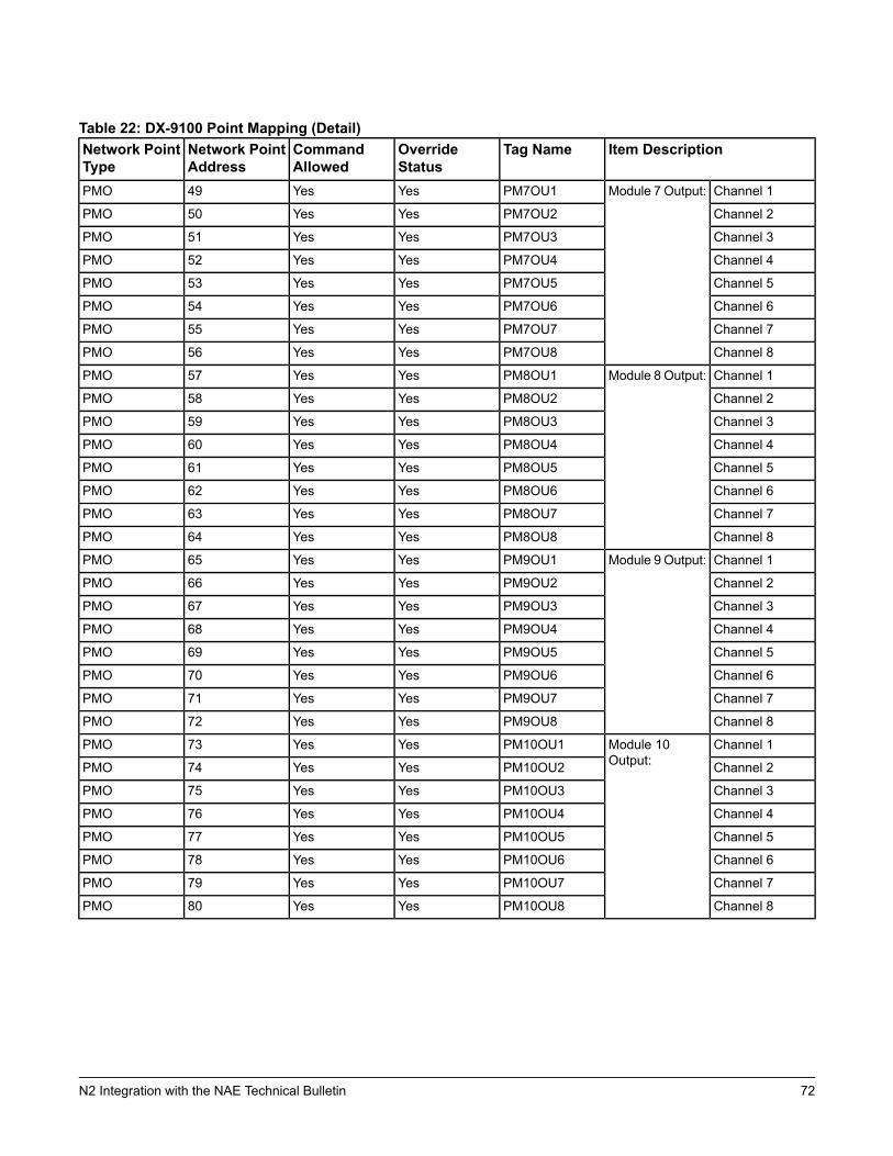
Table 22: DX-9100 Point Mapping (Detail)Item DescriptionTag NameOverride
StatusCommandAllowed
Network PointAddress
Network PointType
Channel 1Module 7 Output:PM7OU1YesYes49PMO
Channel 2PM7OU2YesYes50PMO
Channel 3PM7OU3YesYes51PMO
Channel 4PM7OU4YesYes52PMO
Channel 5PM7OU5YesYes53PMO
Channel 6PM7OU6YesYes54PMO
Channel 7PM7OU7YesYes55PMO
Channel 8PM7OU8YesYes56PMO
Channel 1Module 8 Output:PM8OU1YesYes57PMO
Channel 2PM8OU2YesYes58PMO
Channel 3PM8OU3YesYes59PMO
Channel 4PM8OU4YesYes60PMO
Channel 5PM8OU5YesYes61PMO
Channel 6PM8OU6YesYes62PMO
Channel 7PM8OU7YesYes63PMO
Channel 8PM8OU8YesYes64PMO
Channel 1Module 9 Output:PM9OU1YesYes65PMO
Channel 2PM9OU2YesYes66PMO
Channel 3PM9OU3YesYes67PMO
Channel 4PM9OU4YesYes68PMO
Channel 5PM9OU5YesYes69PMO
Channel 6PM9OU6YesYes70PMO
Channel 7PM9OU7YesYes71PMO
Channel 8PM9OU8YesYes72PMO
Channel 1Module 10Output:
PM10OU1YesYes73PMO
Channel 2PM10OU2YesYes74PMO
Channel 3PM10OU3YesYes75PMO
Channel 4PM10OU4YesYes76PMO
Channel 5PM10OU5YesYes77PMO
Channel 6PM10OU6YesYes78PMO
Channel 7PM10OU7YesYes79PMO
Channel 8PM10OU8YesYes80PMO
72N2 Integration with the NAE Technical Bulletin
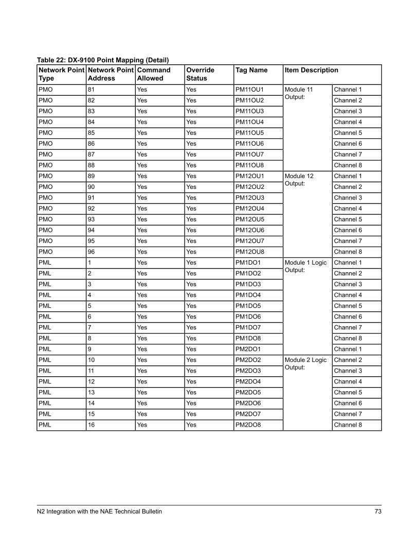
Table 22: DX-9100 Point Mapping (Detail)Item DescriptionTag NameOverride
StatusCommandAllowed
Network PointAddress
Network PointType
Channel 1Module 11Output:
PM11OU1YesYes81PMO
Channel 2PM11OU2YesYes82PMO
Channel 3PM11OU3YesYes83PMO
Channel 4PM11OU4YesYes84PMO
Channel 5PM11OU5YesYes85PMO
Channel 6PM11OU6YesYes86PMO
Channel 7PM11OU7YesYes87PMO
Channel 8PM11OU8YesYes88PMO
Channel 1Module 12Output:
PM12OU1YesYes89PMO
Channel 2PM12OU2YesYes90PMO
Channel 3PM12OU3YesYes91PMO
Channel 4PM12OU4YesYes92PMO
Channel 5PM12OU5YesYes93PMO
Channel 6PM12OU6YesYes94PMO
Channel 7PM12OU7YesYes95PMO
Channel 8PM12OU8YesYes96PMO
Channel 1Module 1 LogicOutput:
PM1DO1YesYes1PML
Channel 2PM1DO2YesYes2PML
Channel 3PM1DO3YesYes3PML
Channel 4PM1DO4YesYes4PML
Channel 5PM1DO5YesYes5PML
Channel 6PM1DO6YesYes6PML
Channel 7PM1DO7YesYes7PML
Channel 8PM1DO8YesYes8PML
Channel 1PM2DO1YesYes9PML
Channel 2Module 2 LogicOutput:
PM2DO2YesYes10PML
Channel 3PM2DO3YesYes11PML
Channel 4PM2DO4YesYes12PML
Channel 5PM2DO5YesYes13PML
Channel 6PM2DO6YesYes14PML
Channel 7PM2DO7YesYes15PML
Channel 8PM2DO8YesYes16PML
73N2 Integration with the NAE Technical Bulletin

Table 22: DX-9100 Point Mapping (Detail)Item DescriptionTag NameOverride
StatusCommandAllowed
Network PointAddress
Network PointType
Channel 1Module 3 LogicOutput:
PM3DO1YesYes17PML
Channel 2PM3DO2YesYes18PML
Channel 3PM3DO3YesYes19PML
Channel 4PM3DO4YesYes20PML
Channel 5PM3DO5YesYes21PML
Channel 6PM3DO6YesYes22PML
Channel 7PM3DO7YesYes23PML
Channel 8PM3DO8YesYes24PML
Channel 1Module 4 LogicOutput:
PM4DO1YesYes25PML
Channel 2PM4DO2YesYes26PML
Channel 3PM4DO3YesYes27PML
Channel 4PM4DO4YesYes28PML
Channel 5PM4DO5YesYes29PML
Channel 6PM4DO6YesYes30PML
Channel 7PM4DO7YesYes31PML
Channel 8PM4DO8YesYes32PML
Channel 1Module 5 LogicOutput:
PM5DO1YesYes33PML
Channel 2PM5DO2YesYes34PML
Channel 3PM5DO3YesYes35PML
Channel 4PM5DO4YesYes36PML
Channel 5PM5DO5YesYes37PML
Channel 6PM5DO6YesYes38PML
Channel 7PM5DO7YesYes39PML
Channel 8PM5DO8YesYes40PML
Channel 1Module 6 LogicOutput:
PM6DO1YesYes41PML
Channel 2PM6DO2YesYes42PML
Channel 3PM6DO3YesYes43PML
Channel 4PM6DO4YesYes44PML
Channel 5PM6DO5YesYes45PML
Channel 6PM6DO6YesYes46PML
Channel 7PM6DO7YesYes47PML
Channel 8PM6DO8YesYes48PML
74N2 Integration with the NAE Technical Bulletin

Table 22: DX-9100 Point Mapping (Detail)Item DescriptionTag NameOverride
StatusCommandAllowed
Network PointAddress
Network PointType
Channel 1Module 7 LogicOutput:
PM7DO1YesYes49PML
Channel 2PM7DO2YesYes50PML
Channel 3PM7DO3YesYes51PML
Channel 4PM7DO4YesYes52PML
Channel 5PM7DO5YesYes53PML
Channel 6PM7DO6YesYes54PML
Channel 7PM7DO7YesYes55PML
Channel 8PM7DO8YesYes56PML
Channel 1Module 8 LogicOutput:
PM8DO1YesYes57PML
Channel 2PM8DO2YesYes58PML
Channel 3PM8DO3YesYes59PML
Channel 4PM8DO4YesYes60PML
Channel 5PM8DO5YesYes61PML
Channel 6PM8DO6YesYes62PML
Channel 7PM8DO7YesYes63PML
Channel 8PM8DO8YesYes64PML
Channel 1Module 9 LogicOutput:
PM9DO1YesYes65PML
Channel 2PM9DO2YesYes66PML
Channel 3PM9DO3YesYes67PML
Channel 4PM9DO4YesYes68PML
Channel 5PM9DO5YesYes69PML
Channel 6PM9DO6YesYes70PML
Channel 7PM9DO7YesYes71PML
Channel 8PM9DO8YesYes72PML
Channel 1Module 10 LogicOutput:
PM10DO1YesYes73PML
Channel 2PM10DO2YesYes74PML
Channel 3PM10DO3YesYes75PML
Channel 4PM10DO4YesYes76PML
Channel 5PM10DO5YesYes77PML
Channel 6PM10DO6YesYes78PML
Channel 7PM10DO7YesYes79PML
Channel 8PM10DO8YesYes80PML
75N2 Integration with the NAE Technical Bulletin
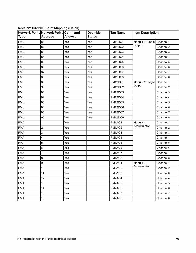
Table 22: DX-9100 Point Mapping (Detail)Item DescriptionTag NameOverride
StatusCommandAllowed
Network PointAddress
Network PointType
Channel 1Module 11 LogicOutput:
PM11DO1YesYes81PML
Channel 2PM11DO2YesYes82PML
Channel 3PM11DO3YesYes83PML
Channel 4PM11DO4YesYes84PML
Channel 5PM11DO5YesYes85PML
Channel 6PM11DO6YesYes86PML
Channel 7PM11DO7YesYes87PML
Channel 8PM11DO8YesYes88PML
Channel 1Module 12 LogicOutput
PM12DO1YesYes89PML
Channel 2PM12DO2YesYes90PML
Channel 3PM12DO3YesYes91PML
Channel 4PM12DO4YesYes92PML
Channel 5PM12DO5YesYes93PML
Channel 6PM12DO6YesYes94PML
Channel 7PM12DO7YesYes95PML
Channel 8PM12DO8YesYes96PML
Channel 1Module 1Accumulator:
PM1AC1Yes1PMA
Channel 2PM1AC2Yes2PMA
Channel 3PM1AC3Yes3PMA
Channel 4PM1AC4Yes4PMA
Channel 5PM1AC5Yes5PMA
Channel 6PM1AC6Yes6PMA
Channel 7PM1AC7Yes7PMA
Channel 8PM1AC8Yes8PMA
Channel 1Module 2Accumulator:
PM2AC1Yes9PMA
Channel 2PM2AC2Yes10PMA
Channel 3PM2AC3Yes11PMA
Channel 4PM2AC4Yes12PMA
Channel 5PM2AC5Yes13PMA
Channel 6PM2AC6Yes14PMA
Channel 7PM2AC7Yes15PMA
Channel 8PM2AC8Yes16PMA
76N2 Integration with the NAE Technical Bulletin

Table 22: DX-9100 Point Mapping (Detail)Item DescriptionTag NameOverride
StatusCommandAllowed
Network PointAddress
Network PointType
Channel 1Module 3Accumulator:
PM3AC1Yes17PMA
Channel 2PM3AC2Yes18PMA
Channel 3PM3AC3Yes19PMA
Channel 4PM3AC4Yes20PMA
Channel 5PM3AC5Yes21PMA
Channel 6PM3AC6Yes22PMA
Channel 7PM3AC7Yes23PMA
Channel 8PM3AC8Yes24PMA
Channel 1Module 4Accumulator:
PM4AC1Yes25PMA
Channel 2PM4AC2Yes26PMA
Channel 3PM4AC3Yes27PMA
Channel 4PM4AC4Yes28PMA
Channel 5PM4AC5Yes29PMA
Channel 6PM4AC6Yes30PMA
Channel 7PM4AC7Yes31PMA
Channel 8PM4AC8Yes32PMA
Channel 1Module 5Accumulator:
PM5AC1Yes33PMA
Channel 2PM5AC2Yes34PMA
Channel 3PM5AC3Yes35PMA
Channel 4PM5AC4Yes36PMA
Channel 5PM5AC5Yes37PMA
Channel 6PM5AC6Yes38PMA
Channel 7PM5AC7Yes39PMA
Channel 8PM5AC8Yes40PMA
Channel 1Module 6Accumulator:
PM6AC1Yes41PMA
Channel 2PM6AC2Yes42PMA
Channel 3PM6AC3Yes43PMA
Channel 4PM6AC4Yes44PMA
Channel 5PM6AC5Yes45PMA
Channel 6PM6AC6Yes46PMA
Channel 7PM6AC7Yes47PMA
Channel 8PM6AC8Yes48PMA
77N2 Integration with the NAE Technical Bulletin
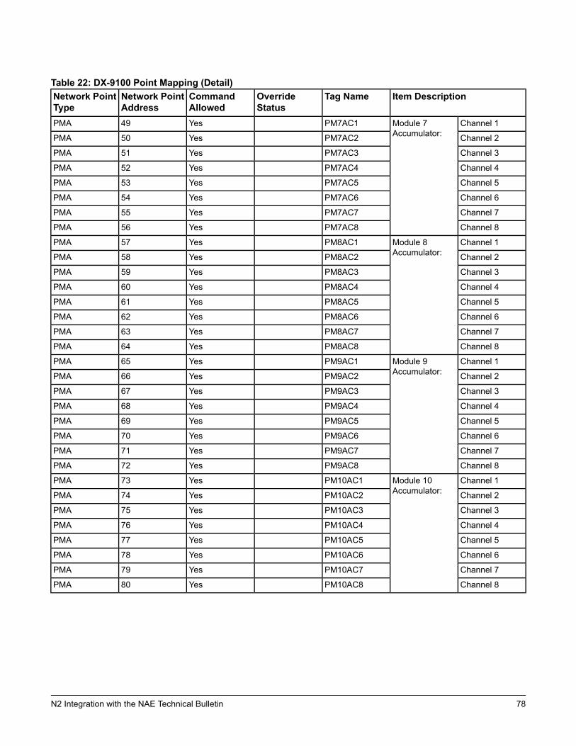
Table 22: DX-9100 Point Mapping (Detail)Item DescriptionTag NameOverride
StatusCommandAllowed
Network PointAddress
Network PointType
Channel 1Module 7Accumulator:
PM7AC1Yes49PMA
Channel 2PM7AC2Yes50PMA
Channel 3PM7AC3Yes51PMA
Channel 4PM7AC4Yes52PMA
Channel 5PM7AC5Yes53PMA
Channel 6PM7AC6Yes54PMA
Channel 7PM7AC7Yes55PMA
Channel 8PM7AC8Yes56PMA
Channel 1Module 8Accumulator:
PM8AC1Yes57PMA
Channel 2PM8AC2Yes58PMA
Channel 3PM8AC3Yes59PMA
Channel 4PM8AC4Yes60PMA
Channel 5PM8AC5Yes61PMA
Channel 6PM8AC6Yes62PMA
Channel 7PM8AC7Yes63PMA
Channel 8PM8AC8Yes64PMA
Channel 1Module 9Accumulator:
PM9AC1Yes65PMA
Channel 2PM9AC2Yes66PMA
Channel 3PM9AC3Yes67PMA
Channel 4PM9AC4Yes68PMA
Channel 5PM9AC5Yes69PMA
Channel 6PM9AC6Yes70PMA
Channel 7PM9AC7Yes71PMA
Channel 8PM9AC8Yes72PMA
Channel 1Module 10Accumulator:
PM10AC1Yes73PMA
Channel 2PM10AC2Yes74PMA
Channel 3PM10AC3Yes75PMA
Channel 4PM10AC4Yes76PMA
Channel 5PM10AC5Yes77PMA
Channel 6PM10AC6Yes78PMA
Channel 7PM10AC7Yes79PMA
Channel 8PM10AC8Yes80PMA
78N2 Integration with the NAE Technical Bulletin
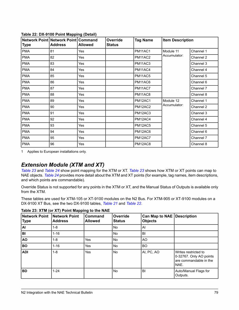
Table 22: DX-9100 Point Mapping (Detail)Item DescriptionTag NameOverride
StatusCommandAllowed
Network PointAddress
Network PointType
Channel 1Module 11Accumulator:
PM11AC1Yes81PMA
Channel 2PM11AC2Yes82PMA
Channel 3PM11AC3Yes83PMA
Channel 4PM11AC4Yes84PMA
Channel 5PM11AC5Yes85PMA
Channel 6PM11AC6Yes86PMA
Channel 7PM11AC7Yes87PMA
Channel 8PM11AC8Yes88PMA
Channel 1Module 12Accumulator:
PM12AC1Yes89PMA
Channel 2PM12AC2Yes90PMA
Channel 3PM12AC3Yes91PMA
Channel 4PM12AC4Yes92PMA
Channel 5PM12AC5Yes93PMA
Channel 6PM12AC6Yes94PMA
Channel 7PM12AC7Yes95PMA
Channel 8PM12AC8Yes96PMA
1 Applies to European installations only.
Extension Module (XTM and XT)Table 23 and Table 24 show point mapping for the XTM or XT. Table 23 shows how XTM or XT points can map toNAE objects. Table 24 provides more detail about the XTM and XT points (for example, tag names, item descriptions,and which points are commandable).
Override Status is not supported for any points in the XTM or XT, and the Manual Status of Outputs is available onlyfrom the XTM.
These tables are used for XTM-105 or XT-9100 modules on the N2 Bus. For XTM-905 or XT-9100 modules on aDX-9100 XT Bus, see the two DX-9100 tables, Table 21 and Table 22.
Table 23: XTM (or XT) Point Mapping to the NAEDescriptionCan Map to NAE
ObjectsOverrideStatus
CommandAllowed
Network PointAddress
Network PointType
AINo1-8AI
BINo1-16BI
AONoYes1-8AO
BONoYes1-16BO
Writes restricted to0-32767. Only AO pointsare commandable in theNAE.
AI, PC, AONoYes1-8ADI
Auto/Manual Flags forOutputs.
BINo1-24BD
79N2 Integration with the NAE Technical Bulletin
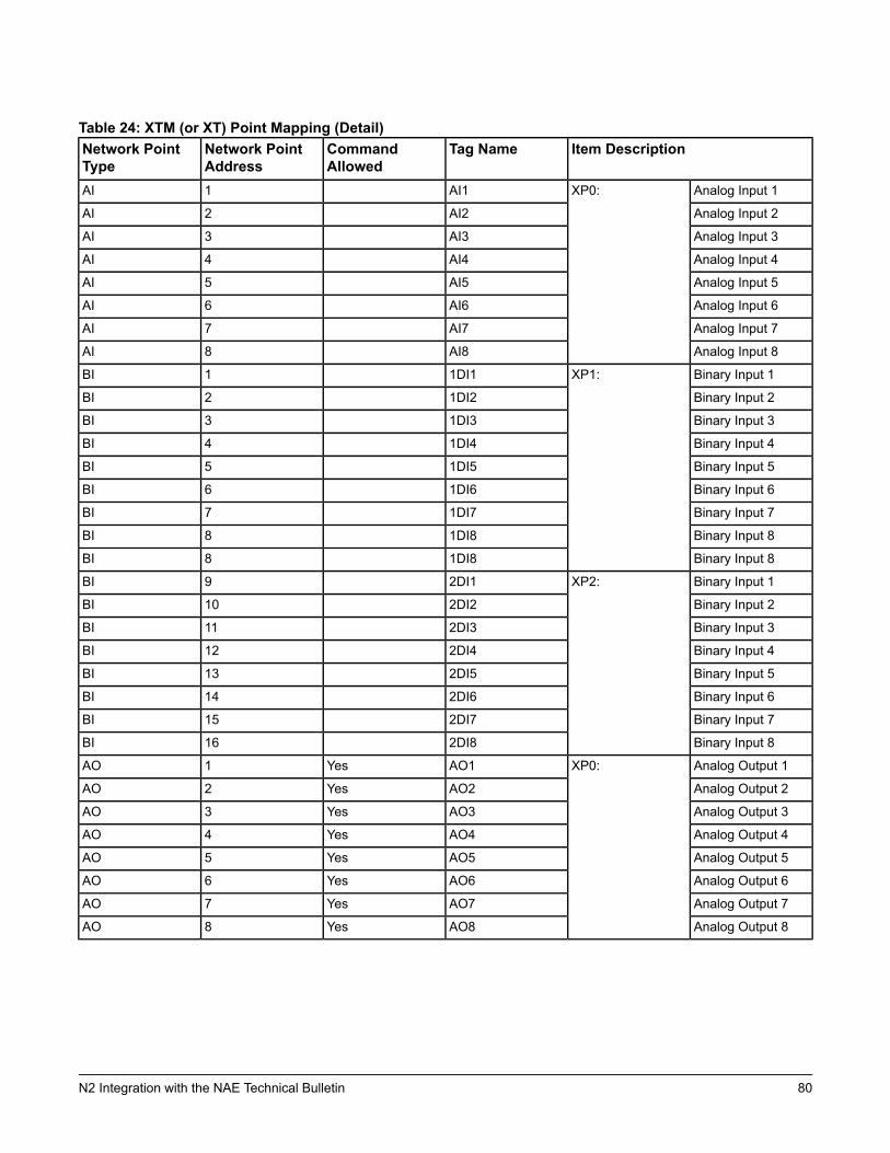
Table 24: XTM (or XT) Point Mapping (Detail)Item DescriptionTag NameCommand
AllowedNetwork PointAddress
Network PointType
Analog Input 1XP0:AI11AI
Analog Input 2AI22AI
Analog Input 3AI33AI
Analog Input 4AI44AI
Analog Input 5AI55AI
Analog Input 6AI66AI
Analog Input 7AI77AI
Analog Input 8AI88AI
Binary Input 1XP1:1DI11BI
Binary Input 21DI22BI
Binary Input 31DI33BI
Binary Input 41DI44BI
Binary Input 51DI55BI
Binary Input 61DI66BI
Binary Input 71DI77BI
Binary Input 81DI88BI
Binary Input 81DI88BI
Binary Input 1XP2:2DI19BI
Binary Input 22DI210BI
Binary Input 32DI311BI
Binary Input 42DI412BI
Binary Input 52DI513BI
Binary Input 62DI614BI
Binary Input 72DI715BI
Binary Input 82DI816BI
Analog Output 1XP0:AO1Yes1AO
Analog Output 2AO2Yes2AO
Analog Output 3AO3Yes3AO
Analog Output 4AO4Yes4AO
Analog Output 5AO5Yes5AO
Analog Output 6AO6Yes6AO
Analog Output 7AO7Yes7AO
Analog Output 8AO8Yes8AO
80N2 Integration with the NAE Technical Bulletin
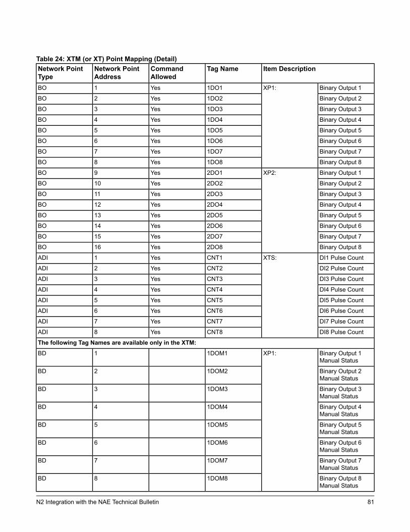
Table 24: XTM (or XT) Point Mapping (Detail)Item DescriptionTag NameCommand
AllowedNetwork PointAddress
Network PointType
Binary Output 1XP1:1DO1Yes1BO
Binary Output 21DO2Yes2BO
Binary Output 31DO3Yes3BO
Binary Output 41DO4Yes4BO
Binary Output 51DO5Yes5BO
Binary Output 61DO6Yes6BO
Binary Output 71DO7Yes7BO
Binary Output 81DO8Yes8BO
Binary Output 1XP2:2DO1Yes9BO
Binary Output 22DO2Yes10BO
Binary Output 32DO3Yes11BO
Binary Output 42DO4Yes12BO
Binary Output 52DO5Yes13BO
Binary Output 62DO6Yes14BO
Binary Output 72DO7Yes15BO
Binary Output 82DO8Yes16BO
DI1 Pulse CountXTS:CNT1Yes1ADI
DI2 Pulse CountCNT2Yes2ADI
DI3 Pulse CountCNT3Yes3ADI
DI4 Pulse CountCNT4Yes4ADI
DI5 Pulse CountCNT5Yes5ADI
DI6 Pulse CountCNT6Yes6ADI
DI7 Pulse CountCNT7Yes7ADI
DI8 Pulse CountCNT8Yes8ADI
The following Tag Names are available only in the XTM:
Binary Output 1Manual Status
XP1:1DOM11BD
Binary Output 2Manual Status
1DOM22BD
Binary Output 3Manual Status
1DOM33BD
Binary Output 4Manual Status
1DOM44BD
Binary Output 5Manual Status
1DOM55BD
Binary Output 6Manual Status
1DOM66BD
Binary Output 7Manual Status
1DOM77BD
Binary Output 8Manual Status
1DOM88BD
81N2 Integration with the NAE Technical Bulletin
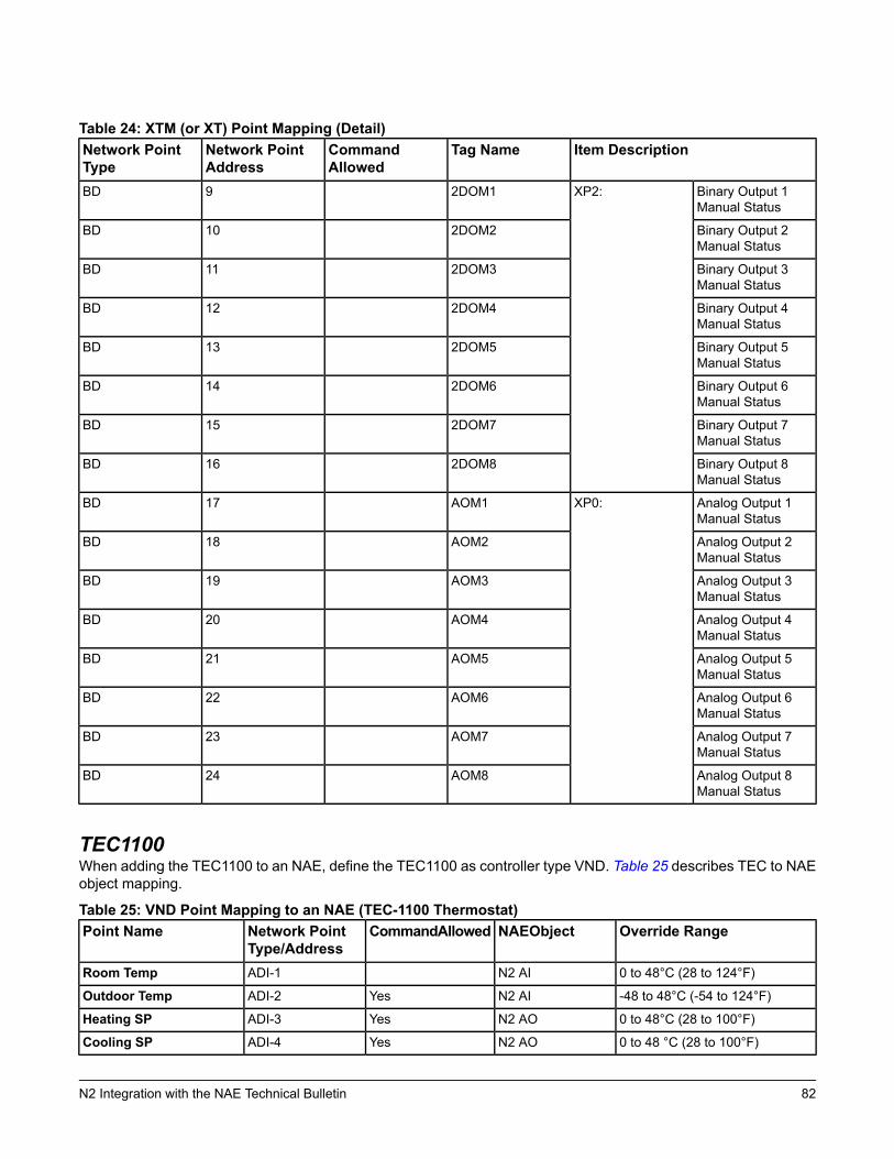
Table 24: XTM (or XT) Point Mapping (Detail)Item DescriptionTag NameCommand
AllowedNetwork PointAddress
Network PointType
Binary Output 1Manual Status
XP2:2DOM19BD
Binary Output 2Manual Status
2DOM210BD
Binary Output 3Manual Status
2DOM311BD
Binary Output 4Manual Status
2DOM412BD
Binary Output 5Manual Status
2DOM513BD
Binary Output 6Manual Status
2DOM614BD
Binary Output 7Manual Status
2DOM715BD
Binary Output 8Manual Status
2DOM816BD
Analog Output 1Manual Status
XP0:AOM117BD
Analog Output 2Manual Status
AOM218BD
Analog Output 3Manual Status
AOM319BD
Analog Output 4Manual Status
AOM420BD
Analog Output 5Manual Status
AOM521BD
Analog Output 6Manual Status
AOM622BD
Analog Output 7Manual Status
AOM723BD
Analog Output 8Manual Status
AOM824BD
TEC1100When adding the TEC1100 to an NAE, define the TEC1100 as controller type VND. Table 25 describes TEC to NAEobject mapping.
Table 25: VND Point Mapping to an NAE (TEC-1100 Thermostat)Override RangeNAEObjectCommandAllowedNetwork Point
Type/AddressPoint Name
0 to 48°C (28 to 124°F)N2 AIADI-1Room Temp
-48 to 48°C (-54 to 124°F)N2 AIYesADI-2Outdoor Temp
0 to 48°C (28 to 100°F)N2 AOYesADI-3Heating SP
0 to 48 °C (28 to 100°F)N2 AOYesADI-4Cooling SP
82N2 Integration with the NAE Technical Bulletin
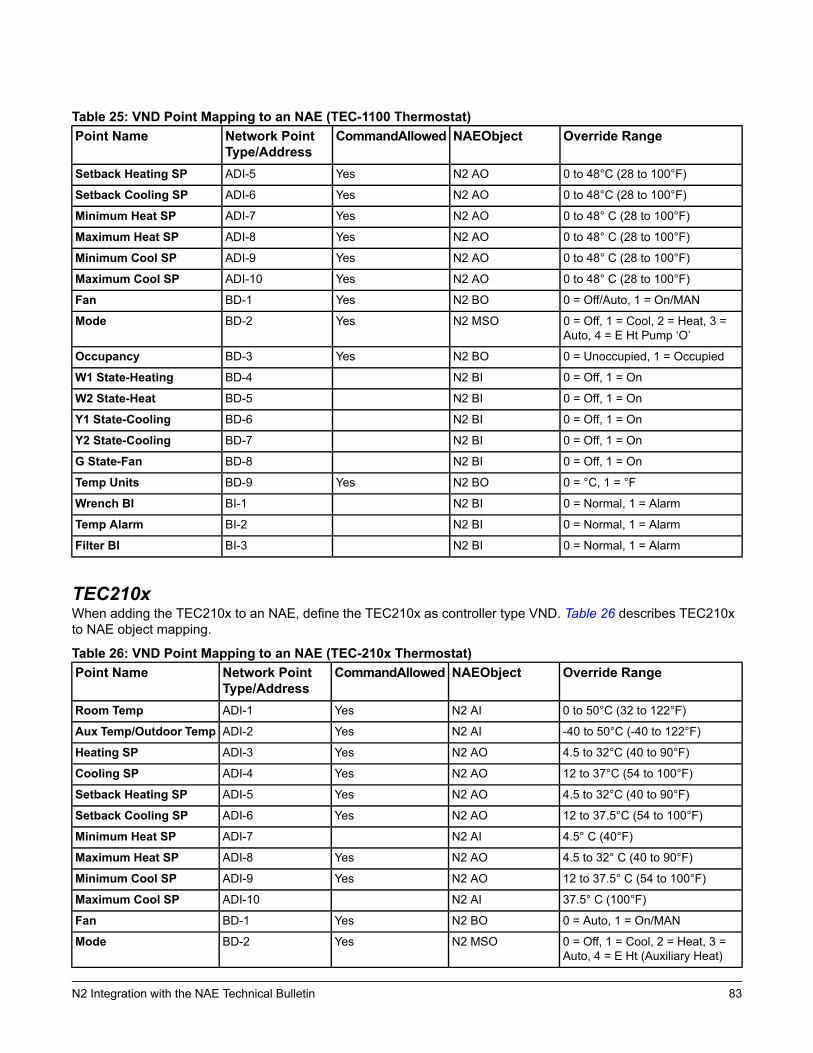
Table 25: VND Point Mapping to an NAE (TEC-1100 Thermostat)Override RangeNAEObjectCommandAllowedNetwork Point
Type/AddressPoint Name
0 to 48°C (28 to 100°F)N2 AOYesADI-5Setback Heating SP
0 to 48°C (28 to 100°F)N2 AOYesADI-6Setback Cooling SP
0 to 48° C (28 to 100°F)N2 AOYesADI-7Minimum Heat SP
0 to 48° C (28 to 100°F)N2 AOYesADI-8Maximum Heat SP
0 to 48° C (28 to 100°F)N2 AOYesADI-9Minimum Cool SP
0 to 48° C (28 to 100°F)N2 AOYesADI-10Maximum Cool SP
0 = Off/Auto, 1 = On/MANN2 BOYesBD-1Fan
0 = Off, 1 = Cool, 2 = Heat, 3 =Auto, 4 = E Ht Pump ‘O’
N2 MSOYesBD-2Mode
0 = Unoccupied, 1 = OccupiedN2 BOYesBD-3Occupancy
0 = Off, 1 = OnN2 BIBD-4W1 State-Heating
0 = Off, 1 = OnN2 BIBD-5W2 State-Heat
0 = Off, 1 = OnN2 BIBD-6Y1 State-Cooling
0 = Off, 1 = OnN2 BIBD-7Y2 State-Cooling
0 = Off, 1 = OnN2 BIBD-8G State-Fan
0 = °C, 1 = °FN2 BOYesBD-9Temp Units
0 = Normal, 1 = AlarmN2 BIBI-1Wrench BI
0 = Normal, 1 = AlarmN2 BIBI-2Temp Alarm
0 = Normal, 1 = AlarmN2 BIBI-3Filter BI
TEC210xWhen adding the TEC210x to an NAE, define the TEC210x as controller type VND. Table 26 describes TEC210xto NAE object mapping.
Table 26: VND Point Mapping to an NAE (TEC-210x Thermostat)Override RangeNAEObjectCommandAllowedNetwork Point
Type/AddressPoint Name
0 to 50°C (32 to 122°F)N2 AIYesADI-1Room Temp
-40 to 50°C (-40 to 122°F)N2 AIYesADI-2Aux Temp/Outdoor Temp
4.5 to 32°C (40 to 90°F)N2 AOYesADI-3Heating SP
12 to 37°C (54 to 100°F)N2 AOYesADI-4Cooling SP
4.5 to 32°C (40 to 90°F)N2 AOYesADI-5Setback Heating SP
12 to 37.5°C (54 to 100°F)N2 AOYesADI-6Setback Cooling SP
4.5° C (40°F)N2 AIADI-7Minimum Heat SP
4.5 to 32° C (40 to 90°F)N2 AOYesADI-8Maximum Heat SP
12 to 37.5° C (54 to 100°F)N2 AOYesADI-9Minimum Cool SP
37.5° C (100°F)N2 AIADI-10Maximum Cool SP
0 = Auto, 1 = On/MANN2 BOYesBD-1Fan
0 = Off, 1 = Cool, 2 = Heat, 3 =Auto, 4 = E Ht (Auxiliary Heat)
N2 MSOYesBD-2Mode
83N2 Integration with the NAE Technical Bulletin
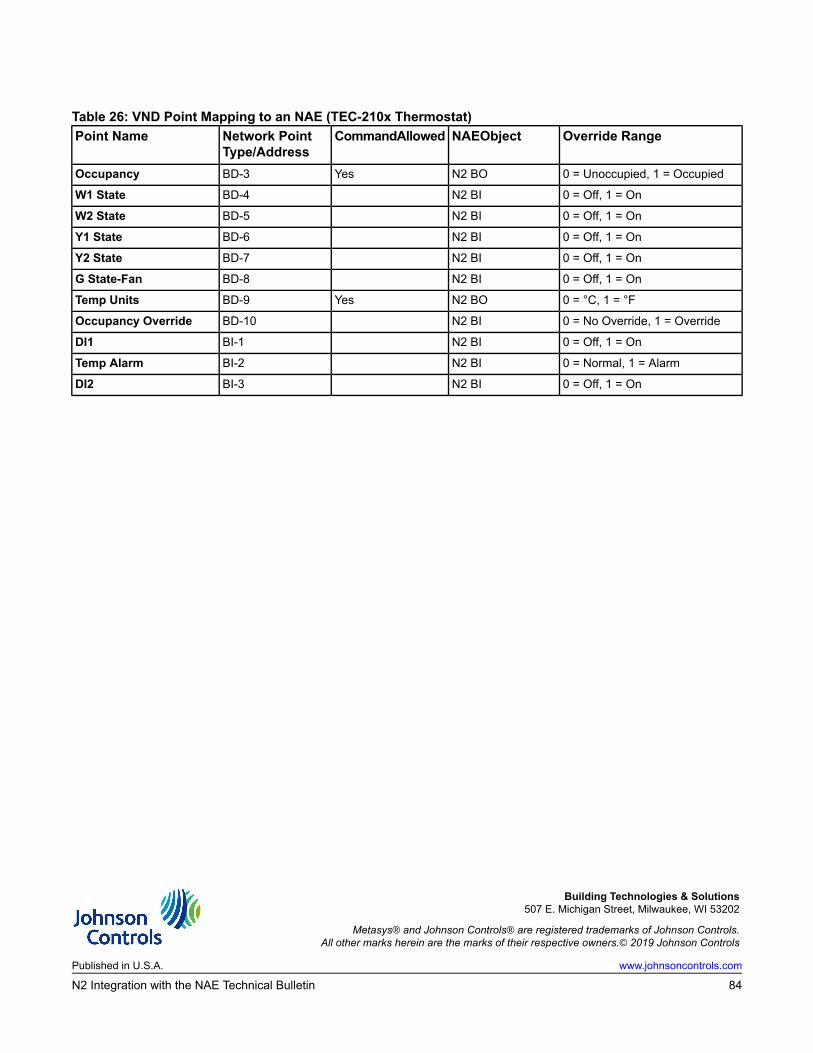
Table 26: VND Point Mapping to an NAE (TEC-210x Thermostat)Override RangeNAEObjectCommandAllowedNetwork Point
Type/AddressPoint Name
0 = Unoccupied, 1 = OccupiedN2 BOYesBD-3Occupancy
0 = Off, 1 = OnN2 BIBD-4W1 State
0 = Off, 1 = OnN2 BIBD-5W2 State
0 = Off, 1 = OnN2 BIBD-6Y1 State
0 = Off, 1 = OnN2 BIBD-7Y2 State
0 = Off, 1 = OnN2 BIBD-8G State-Fan
0 = °C, 1 = °FN2 BOYesBD-9Temp Units
0 = No Override, 1 = OverrideN2 BIBD-10Occupancy Override
0 = Off, 1 = OnN2 BIBI-1DI1
0 = Normal, 1 = AlarmN2 BIBI-2Temp Alarm
0 = Off, 1 = OnN2 BIBI-3DI2
Building Technologies & Solutions507 E. Michigan Street, Milwaukee, WI 53202
Metasys® and Johnson Controls® are registered trademarks of Johnson Controls.All other marks herein are the marks of their respective owners.© 2019 Johnson Controls
www.johnsoncontrols.comPublished in U.S.A.
84N2 Integration with the NAE Technical Bulletin