n120 140 165 195el12 en - home - premier platforms
TRANSCRIPT

Instruction manual(translation of the original text)Combistar Scissor liftHL-140 E12 / N-120EL12HL-160 E12 / N-140EL12HL-190 E12 / N-165EL12HL-220 E12 / N-195EL12
HL-140 E12 / HL-160 E12 / HL-190 E12 / HL-220 E12N-120EL12 / N-140EL12 / N-165EL12 / N-195EL12Rev. F
8/2/18 Page 2
© 2014, HOLLAND LIFT INTERNATIONAL B.V., Hoorn, The Netherlands.
No part of this publication may be copied and/or published by means of printing, photocopying, microfilm or any other way
whatsoever, without the prior written permission of HOLLAND LIFT INTERNATIONAL B.V.

HL-140 E12 / HL-160 E12 / HL-190 E12 / HL-220 E12N-120EL12 / N-140EL12 / N-165EL12 / N-195EL12Rev. F
Page 3 8/2/18
Contents Page
1 General information ................................................................................................................................ 61.1 Use of this instruction manual .................................................................................................................. 61.1.1 Objective .................................................................................................................................................. 61.1.2 Symbols used in this instruction manual .................................................................................................. 61.2 Standard equipment ................................................................................................................................. 61.3 Additional documentation ......................................................................................................................... 61.4 Options ..................................................................................................................................................... 71.5 CE marking............................................................................................................................................... 71.6 Scissor lift identification (type plate) ......................................................................................................... 71.6.1 Location of the type plate ......................................................................................................................... 71.7 Terms of delivery and warranty ................................................................................................................ 81.7.1 Terms of delivery...................................................................................................................................... 81.7.2 Warranty................................................................................................................................................... 81.8 Intended use and modifications................................................................................................................ 81.8.1 Intended use............................................................................................................................................. 81.8.2 Modifications ............................................................................................................................................ 81.9 Service and technical support .................................................................................................................. 9
2 Safety.................................................................................................................................................... 102.1 Emergency procedures .......................................................................................................................... 102.1.1 Emergency stop ..................................................................................................................................... 102.1.2 Contact with high-voltage power lines.................................................................................................... 102.2 Safety instructions .................................................................................................................................. 102.2.1 General information................................................................................................................................ 102.2.2 Safety instructions during normal use .................................................................................................... 112.2.3 Safety instructions during maintenance ................................................................................................. 122.2.4 Safety instructions when working on the electrical system .................................................................... 122.2.5 Safety instructions when working on the hydraulic system .................................................................... 122.3 Liability ................................................................................................................................................... 132.4 Users ...................................................................................................................................................... 132.5 Intended use........................................................................................................................................... 132.6 Decals on the scissor lift......................................................................................................................... 142.6.1 Decals on the front ................................................................................................................................. 142.6.2 Decals on the left side ............................................................................................................................ 152.6.3 Decals on the right side.......................................................................................................................... 162.6.4 Decal emergency descent protection ..................................................................................................... 172.6.5 Decals on the control box and on the platform....................................................................................... 172.6.6 Decals in the left-side compartments ..................................................................................................... 192.7 Location of the safety provisions on the scissor lift ................................................................................ 202.7.1 Emergency stop button .......................................................................................................................... 212.7.2 Dead man's switch ................................................................................................................................. 212.7.3 Safety prop ............................................................................................................................................. 212.7.4 Protective guardrail ................................................................................................................................ 212.7.5 Visual driving alarm/descent protection.................................................................................................. 212.7.6 Pipe/hose rupture safety device ............................................................................................................. 212.7.7 Emergency descent device ................................................................................................................... 222.7.8 Acoustic driving alarm/descent protection.............................................................................................. 222.7.9 Speed limiter .......................................................................................................................................... 222.7.10 Tilt indicators .......................................................................................................................................... 232.7.11 Other safety provisions........................................................................................................................... 23
HL-140 E12 / HL-160 E12 / HL-190 E12 / HL-220 E12N-120EL12 / N-140EL12 / N-165EL12 / N-195EL12Rev. F
8/2/18 Page 4
3 Controls................................................................................................................................................. 263.1 Overview ................................................................................................................................................ 263.2 The control box....................................................................................................................................... 273.2.1 The control panel.................................................................................................................................... 283.3 Main switch............................................................................................................................................. 29
4 Machine compartments......................................................................................................................... 304.1 Introduction............................................................................................................................................. 304.2 Battery compartments ............................................................................................................................ 304.3 Electrical box .......................................................................................................................................... 314.4 Hydraulic oil compartment...................................................................................................................... 324.5 Auxiliary switch raise/descend ............................................................................................................... 334.6 Mains plug for battery charger................................................................................................................ 33
5 Normal use............................................................................................................................................ 345.1 Preparations before use ......................................................................................................................... 345.2 Starting ................................................................................................................................................... 345.3 Switching off ........................................................................................................................................... 365.4 Platform during transport ........................................................................................................................ 365.5 Battery state-of-charge meter................................................................................................................. 37
6 Transport............................................................................................................................................... 396.1 Towing.................................................................................................................................................... 396.1.1 Introduction............................................................................................................................................. 396.1.2 Releasing the multiple disc brakes......................................................................................................... 396.1.3 Point of special interest .......................................................................................................................... 406.2 Transport ................................................................................................................................................ 406.2.1 Introduction............................................................................................................................................. 406.2.2 Preparation............................................................................................................................................. 416.2.3 Points of attention................................................................................................................................... 41
7 Maintenance ......................................................................................................................................... 427.1 Maintenance overview............................................................................................................................ 427.1.1 Protective guardrail ................................................................................................................................ 437.2 Overviews............................................................................................................................................... 447.2.1 Lubrication points ................................................................................................................................... 447.2.2 Tightening torques.................................................................................................................................. 457.3 Maintenance procedures........................................................................................................................ 457.3.1 Installing and removing the safety props................................................................................................ 457.3.2 Topping up the hydraulic system............................................................................................................ 467.3.3 Lubrication.............................................................................................................................................. 467.3.4 Check the tilt safety device..................................................................................................................... 467.3.5 Inspecting the scissor mechanism ......................................................................................................... 47
8 Troubleshooting .................................................................................................................................... 48
9 Disposal ................................................................................................................................................ 499.1 Introduction............................................................................................................................................. 499.2 Disposal procedure ................................................................................................................................ 49
10 Technical specifications........................................................................................................................ 5010.1 Technical specifications for HL-140 E12 / N-120EL12 .......................................................................... 5010.2 Technical specifications for HL-160 E12 / N-140EL12........................................................................... 5110.3 Technical specifications for HL-190 E12 / N-165EL12........................................................................... 5210.4 Technical specifications for HL-220 E12 / N-195EL12........................................................................... 53

HL-140 E12 / HL-160 E12 / HL-190 E12 / HL-220 E12N-120EL12 / N-140EL12 / N-165EL12 / N-195EL12Rev. F
Page 5 8/2/18
11 EC Declaration...................................................................................................................................... 54

HL-140 E12 / HL-160 E12 / HL-190 E12 / HL-220 E12N-120EL12 / N-140EL12 / N-165EL12 / N-195EL12Rev. F
8/2/18 Page 6
1 General information
1.1 Use of this instruction manual
1.1.1 ObjectiveThis instruction manual is intended for the users of the following scissor lifts:
HL-140 E12 / N-120EL12
HL-160 E12 / N-140EL12
HL-190 E12 / N-165EL12
HL-220 E12 / N-195EL12
1.1.2 Symbols used in this instruction manual
1.2 Standard equipment
Control box with a plug-in connection, which can be used on the platform and on the bottom
carriage.
Auxiliary switch for raising and lowering, on the electrical box.
Proportional drive.
Emergency descent device
Driving alarm.
Non-marking tyres
1.3 Additional documentation
Parts list.
Electrical and hydraulic diagram.
Scissor lift book (logbook).
Battery charger manual.
Documentation set for central grease lubrication system (option).
Comment
A comment gives additional information.
Note!
Failure to heed an instruction with this symbol and text may result in damage to the scissor
lift.
Warning
Failure to heed an instruction with this symbol and text may result in serious physical injury
or serious damage to the scissor lift.
HL-140 E12 / HL-160 E12 / HL-190 E12 / HL-220 E12N-120EL12 / N-140EL12 / N-165EL12 / N-195EL12Rev. F
Page 7 8/2/18
1.4 Options
AC 230 V connection on the platform.
Flashing beacons in addition to the acoustic driving alarm.
Ability to drive the scissor lift when fully extended.
Central grease lubrication system
U.K. specifications
1.5 CE marking
See the Declaration of Conformity.
1.6 Scissor lift identification (type plate)
The type plate contains information specific to the scissor lift.
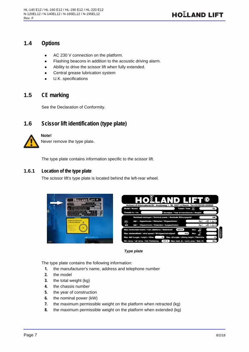
1.6.1 Location of the type plateThe scissor lift's type plate is located behind the left-rear wheel.
The type plate contains the following information:
1. the manufacturer's name, address and telephone number
2. the model
3. the total weight (kg)
4. the chassis number
5. the year of construction
6. the nominal power (kW)
7. the maximum permissible weight on the platform when retracted (kg)
8. the maximum permissible weight on the platform when extended (kg)
Note!
Never remove the type plate.
Type plate
HL-140 E12 / HL-160 E12 / HL-190 E12 / HL-220 E12N-120EL12 / N-140EL12 / N-165EL12 / N-195EL12Rev. F
8/2/18 Page 8
9. the maximum horizontal force (N)
10. the maximum angle of inclination (°)
11. the maximum wind speed (m/s)
12. the maximum tilt (°)
13. the maximum height (m)
14. the maximum height when mobile
15. the minimum permissible temperature (°C)
16. the maximum operating pressure (bar)
1.7 Terms of delivery and warranty
1.7.1 Terms of deliveryAll sales agreements with HOLLAND LIFT INTERNATIONAL B.V. are subject to the Metaalunie
terms and conditions.
1.7.2 WarrantySee the terms of delivery for the length of the warranty.
1.8 Intended use and modifications
1.8.1 Intended useThe scissor lift is only intended to be used to allow people to work at a height. The maximum load of
the platform (see type plate) must not be exceeded under any circumstances. Any other use is
contrary to the scissor lift's intended use. Only use the scissor lift in enclosed spaces with an
ambient temperature of between -15 °C and +40 °C.
1.8.2 ModificationsModifications may only be made to the scissor lift after written permission has been obtained from
the management of HOLLAND LIFT INTERNATIONAL B.V.
The information contained in this instruction manual is based on the information regarding
constructions, material properties and work methods that was known to us at the time of publication.
We therefore reserve the right to make construction modifications. For this reason, HOLLAND LIFT
INTERNATIONAL B.V. also reserves the right to make alterations to the content of the instruction
manual without any prior notice.
Components may only be replaced by components provided by HOLLAND LIFT INTERNATIONAL
B.V. or components which can be considered to be of a comparable quality. HOLLAND LIFT
INTERNATIONAL B.V. reserves the right to decide whether these components are of a comparable
quality. The manufacturer can only be held liable if a written declaration stating that the components
are of comparable quality has been obtained from the manufacturer.
HL-140 E12 / HL-160 E12 / HL-190 E12 / HL-220 E12N-120EL12 / N-140EL12 / N-165EL12 / N-195EL12Rev. F
Page 9 8/2/18
1.9 Service and technical support
HOLLAND LIFT INTERNATIONAL B.V.
Anodeweg 1
1627 LJ Hoorn
The Netherlands
T +31 (0)229-285555
F +31 (0)229-285550
W www.hollandlift.com
HL-140 E12 / HL-160 E12 / HL-190 E12 / HL-220 E12N-120EL12 / N-140EL12 / N-165EL12 / N-195EL12Rev. F
8/2/18 Page 10
2 Safety
2.1 Emergency procedures
2.1.1 Emergency stopTo disable all of the scissor lift's functions:
Press the emergency stop button.
2.1.2 Contact with high-voltage power linesObserve the following if the scissor lift comes into contact with high-voltage power lines:
1. Remain on the platform.
2. Drive the scissor lift out of the danger area.
3. Make sure bystanders do not touch the scissor lift.
4. Have the power disconnected from the high-voltage power lines.
5. Exit the scissor lift when the high-voltage power line is no longer energised.
2.2 Safety instructions
2.2.1 General information Avoid any situation that may endanger the users of the scissor lift or any bystanders.
It is strictly forbidden:
• to lower hanging loads onto the scissor lift
• to use the scissor lift to hoist loads
• to attach advertising boards or banners to the scissor lift
• to increase the surface area of the platform
• to stand on the guardrails surrounding the platform
• to raise the height of the platform floor
• to use any type of ladder on the platform
• to enter or exit the platform in the raised position
• to tow the scissor lift on public roads
After every (major) repair, the scissor lift must be inspected and approved by an expert.
If any modifications or repairs are carried out which may affect the scissor lift's stability,
strength or performance, the scissor lift must be reinspected and approved by HOLLAND
LIFT INTERNATIONAL B.V.
Any inspections, tests, repairs or modifications must be recorded in the scissor lift logbook.
The weighted root mean square acceleration value (vibrations) that the user is subjected to
during use of the scissor lift is not greater than 2.5 m/s².
HL-140 E12 / HL-160 E12 / HL-190 E12 / HL-220 E12N-120EL12 / N-140EL12 / N-165EL12 / N-195EL12Rev. F
Page 11 8/2/18
The noise produced by the scissor lift in the work area at a distance of 7 metres and at
maximum load does not exceed 75 dB(A).
Exposure to the noise over a long period of time may be detrimental to the hearing if hearing
protection is not worn.
2.2.2 Safety instructions during normal use Only use the scissor lift under the following conditions:
• there is no visible damage to the scissor lift
• all the functions work correctly
• all the safety devices work correctly
• the hydraulic system does not leak
• the hydraulic system contains the correct quantity of oil
Lock the covers of the cabinets on the bottom carriage.
Do not touch the moving or pivoting parts of the scissor lift (e.g. the scissor mechanism or the
steering gear).
Make sure the driving area and the work area are:
• sufficiently flat and able to support the weight of the scissor lift
• adequately lit
• free of obstacles
• free of snow and ice
Make sure the scissor lift cannot touch any fixed or moving obstacles.
Make sure no objects can fall from the platform (e.g. tools).
If tools which may cause a fire are used on the platform, a fire extinguisher must be present
on the platform.
The scissor lift may only be driven when fully extended if it is driven in an enclosed space on a
completely flat surface which is able to support the weight of the scissor lift. The user must be
aware of this. An additional safety requirement is that the scissor lift must be operated by two
people at all times. One person must work on the platform and the other person must remain
on the ground. They can maintain contact with each other using communication equipment. In normal situations, the 8-metre stop should work. The key switch is in the ‘0’ position by
default. This means that it is possible to drive the scissor lift when it is extended up to a height
of 8 metres. Position ‘1’ means: it is possible to drive the scissor lift when it is extended to the
maximum height. The maximum speed is 0.5 km/h when the scissor lift is extended above a
height of 4 m. The key switch is located on the electrical box.
Only charge the battery of the scissor lift in an area that is well ventilated and where smoking
and naked flame are prohibited.
Important conditions concerning driving up or down inclines in the scissor lift's longitudinal
direction:
• See the technical information in the instruction manual for the maximum incline that the
scissor lift can be driven on.
• The maximum load when driving up an incline is 80 kg (1 person).
• Place the platform in the lowest position.
• Select the slowest speed.
• Do not make any sharp steering movements when driving up an incline.
• Drive up an incline with the non-driven wheels uphill.

HL-140 E12 / HL-160 E12 / HL-190 E12 / HL-220 E12N-120EL12 / N-140EL12 / N-165EL12 / N-195EL12Rev. F
8/2/18 Page 12
It is strictly forbidden:
• to operate the scissor lift from the ground using the control box (except for transport
reasons or when carrying out maintenance work on the scissor lift)
• to use the scissor lift to carry out work on or near high-voltage electrical lines
• to use the scissor lift to work in an area where there is a risk of explosion
2.2.3 Safety instructions during maintenance Always wear the required safety equipment (e.g. safety goggles, hearing protection, helmet)
when carrying out maintenance work on the scissor lift.
Prevent the scissor lift from being able to roll away. For example, place chocks against the
wheels.
Prevent the risk of crushing in the scissor mechanism. Make sure the safety prop has been
fitted before working on parts such as the scissor mechanism (e.g. lubricating the scissor
mechanism).
If the scissor lift is switched off during maintenance work and must remain off, take measures
to prevent the scissor lift from being switched on unexpectedly or unintentionally. Make sure
others cannot undo the measures that have been taken.
Before cleaning the scissor lift with steam, water or other liquids, protect all components that
must not be exposed to liquids. Remove the protection after cleaning the scissor lift.
Make sure oil, grease and other substances that are harmful to the environment are disposed
of in a safe and environmentally-friendly manner.
2.2.4 Safety instructions when working on the electrical system Turn off the scissor lift before working on the electrical system.
2.2.5 Safety instructions when working on the hydraulic system Make sure the correct fire extinguisher is available. Leaking oil can be hot and may therefore
cause a fire.
Lower the platform as far as possible before carrying out work on the hydraulic system.
Release the pressure before working on the hydraulic system.
Do not touch the hydraulic systems lines. Leaking, hot oil can cause burns or penetrate the
skin. If you come into contact with the oil, immediately contact a doctor who has experience
with this type of injury.
HL-140 E12 / HL-160 E12 / HL-190 E12 / HL-220 E12N-120EL12 / N-140EL12 / N-165EL12 / N-195EL12Rev. F
Page 13 8/2/18
2.3 Liability
HOLLAND LIFT INTERNATIONAL B.V. cannot be held liable for:
damage resulting from negligent use and/or maintenance of the scissor lift
any printing errors in the documentation or their consequences
2.4 Users
The management is obliged to instruct the users of the scissor lift in its use and maintenance
with the aid of the instruction manual, additional instructions and directions.
The instruction manual must be easily accessible to the user at all times in a tube that has
been fitted in the scissor lift's valve/electrical compartment for that purpose. If necessary, HOLLAND LIFT INTERNATIONAL B.V. can provide a new copy on request.
The scissor lift may only be operated by people who are 18 years of age or older, who know
how to operate the scissor lift and who have read and understood the operating instructions
and regulations that are applicable to the HOLLAND LIFT INTERNATIONAL B.V. scissor lift.
It is strictly forbidden for people to operate the scissor lift when they are under the influence of
alcohol, drugs or medicine that impairs their ability to work safely.
In the Netherlands, it is recommended that operators be required to obtain the elevating work
platform safety certificate (Veiligheidscertificaat Hoogwerker). This is recognised by the
Vertical Transport Certification Supervisory Association (TCVT).The IPAF Mobile Elevated Working Platform Operator course is recognised internationally.
Maintenance may only be carried out by people who have read and understood the
instructions contained in the instruction manual and who have specific knowledge of the
operation and construction of the scissor lift manufactured by HOLLAND LIFT
INTERNATIONAL B.V.
2.5 Intended use
Only use the scissor lift for the intended use.
Also see section 1.8.1.
HL-140 E12 / HL-160 E12 / HL-190 E12 / HL-220 E12N-120EL12 / N-140EL12 / N-165EL12 / N-195EL12Rev. F
8/2/18 Page 14
2.6 Decals on the scissor lift
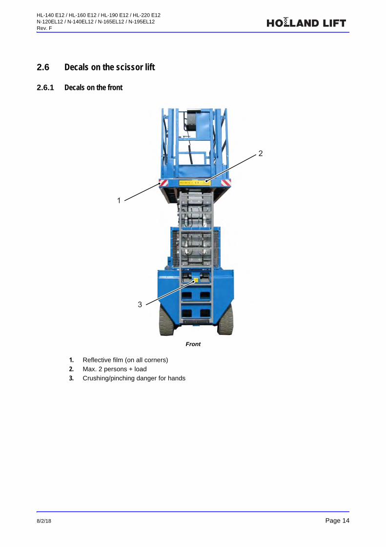
2.6.1 Decals on the front
Front
1. Reflective film (on all corners)
2. Max. 2 persons + load
3. Crushing/pinching danger for hands
2
1
3
HL-140 E12 / HL-160 E12 / HL-190 E12 / HL-220 E12N-120EL12 / N-140EL12 / N-165EL12 / N-195EL12Rev. F
Page 15 8/2/18
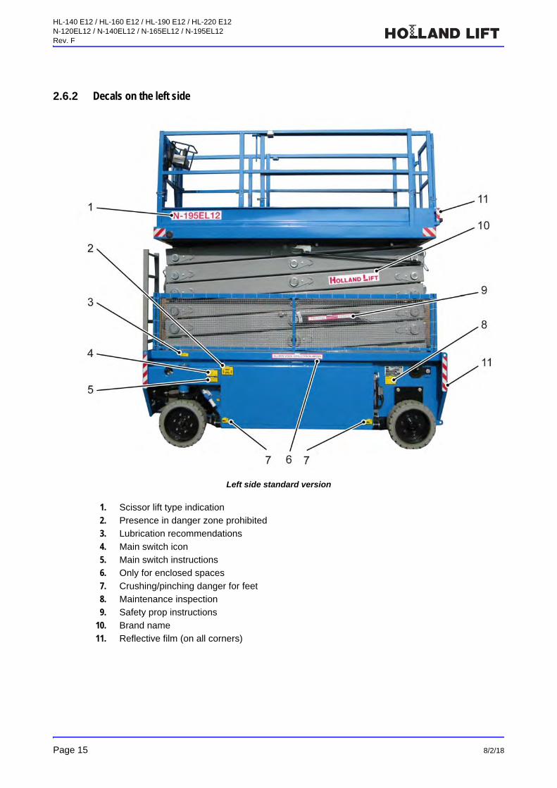
2.6.2 Decals on the left side
Left side standard version
1. Scissor lift type indication
2. Presence in danger zone prohibited
3. Lubrication recommendations
4. Main switch icon
5. Main switch instructions
6. Only for enclosed spaces
7. Crushing/pinching danger for feet
8. Maintenance inspection
9. Safety prop instructions
10. Brand name
11. Reflective film (on all corners)
HL-140 E12 / HL-160 E12 / HL-190 E12 / HL-220 E12N-120EL12 / N-140EL12 / N-165EL12 / N-195EL12Rev. F
8/2/18 Page 16
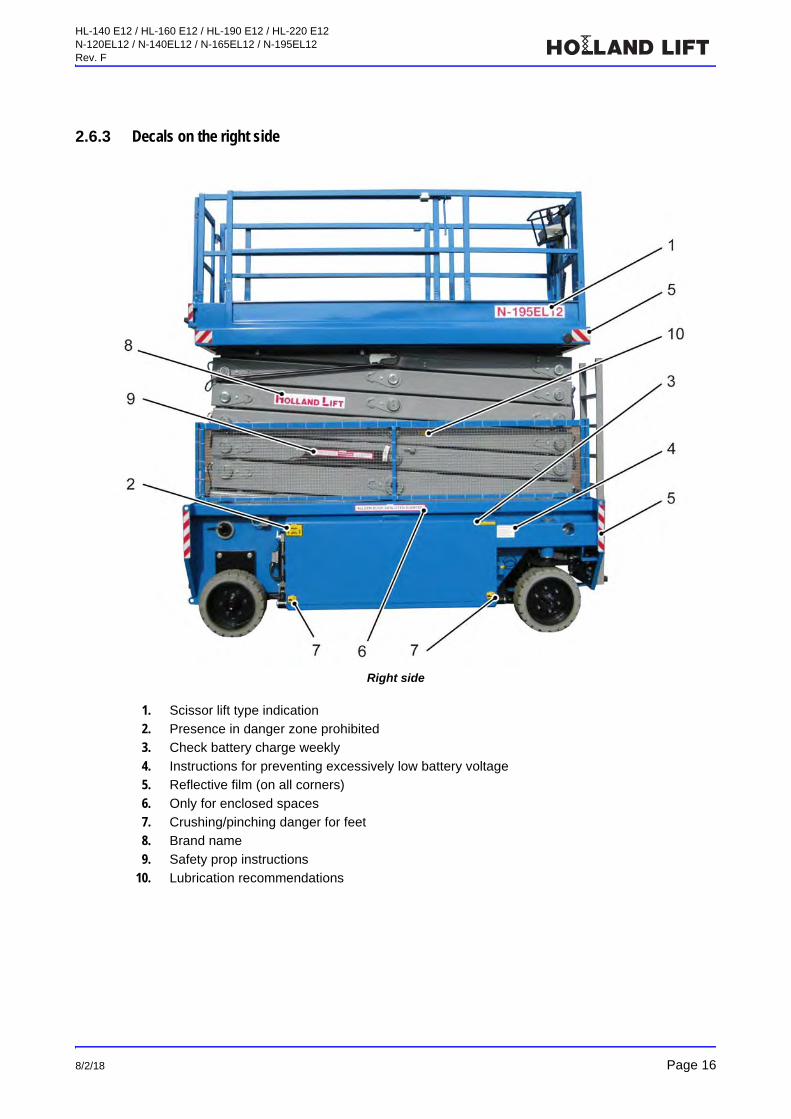
2.6.3 Decals on the right side
Right side
1. Scissor lift type indication
2. Presence in danger zone prohibited
3. Check battery charge weekly
4. Instructions for preventing excessively low battery voltage
5. Reflective film (on all corners)
6. Only for enclosed spaces
7. Crushing/pinching danger for feet
8. Brand name
9. Safety prop instructions
10. Lubrication recommendations

HL-140 E12 / HL-160 E12 / HL-190 E12 / HL-220 E12N-120EL12 / N-140EL12 / N-165EL12 / N-195EL12Rev. F
Page 17 8/2/18
2.6.4 Decal emergency descent protection
Decal emergency descent protection
1. Decal emergency descent protection
2.6.5 Decals on the control box and on the platform
Decals on the inside of the platform
HL-140 E12 / HL-160 E12 / HL-190 E12 / HL-220 E12N-120EL12 / N-140EL12 / N-165EL12 / N-195EL12Rev. F
8/2/18 Page 18
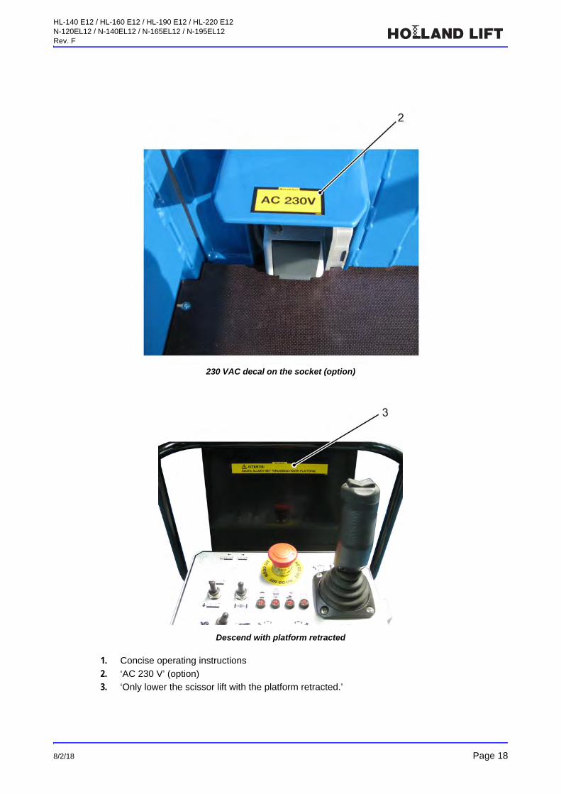
230 VAC decal on the socket (option)
Descend with platform retracted
1. Concise operating instructions
2. ‘AC 230 V’ (option)
3. ‘Only lower the scissor lift with the platform retracted.’
HL-140 E12 / HL-160 E12 / HL-190 E12 / HL-220 E12N-120EL12 / N-140EL12 / N-165EL12 / N-195EL12Rev. F
Page 19 8/2/18
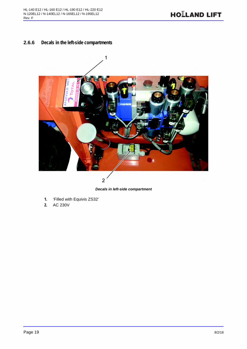
2.6.6 Decals in the left-side compartments
Decals in left-side compartment
1. ‘Filled with Equivis ZS32’
2. AC 230V
HL-140 E12 / HL-160 E12 / HL-190 E12 / HL-220 E12N-120EL12 / N-140EL12 / N-165EL12 / N-195EL12Rev. F
8/2/18 Page 20
2.7 Location of the safety provisions on the scissor lift
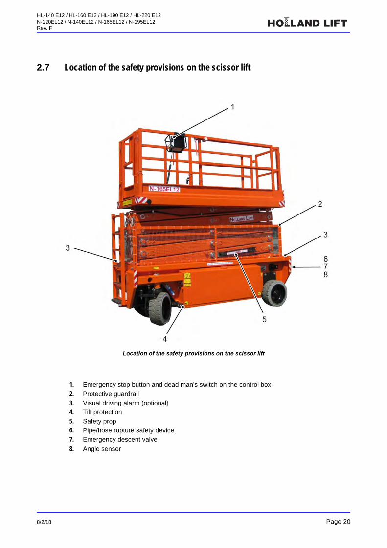
Location of the safety provisions on the scissor lift
1. Emergency stop button and dead man's switch on the control box
2. Protective guardrail
3. Visual driving alarm (optional)
4. Tilt protection
5. Safety prop
6. Pipe/hose rupture safety device
7. Emergency descent valve
8. Angle sensor
HL-140 E12 / HL-160 E12 / HL-190 E12 / HL-220 E12N-120EL12 / N-140EL12 / N-165EL12 / N-195EL12Rev. F
Page 21 8/2/18
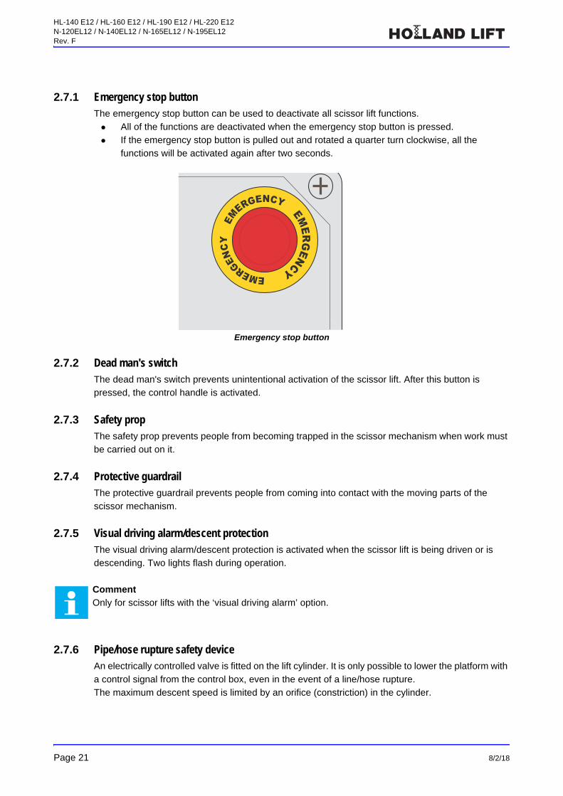
2.7.1 Emergency stop buttonThe emergency stop button can be used to deactivate all scissor lift functions.
All of the functions are deactivated when the emergency stop button is pressed.
If the emergency stop button is pulled out and rotated a quarter turn clockwise, all the
functions will be activated again after two seconds.
Emergency stop button
2.7.2 Dead man's switchThe dead man's switch prevents unintentional activation of the scissor lift. After this button is
pressed, the control handle is activated.
2.7.3 Safety propThe safety prop prevents people from becoming trapped in the scissor mechanism when work must
be carried out on it.
2.7.4 Protective guardrailThe protective guardrail prevents people from coming into contact with the moving parts of the
scissor mechanism.
2.7.5 Visual driving alarm/descent protectionThe visual driving alarm/descent protection is activated when the scissor lift is being driven or is
descending. Two lights flash during operation.
2.7.6 Pipe/hose rupture safety deviceAn electrically controlled valve is fitted on the lift cylinder. It is only possible to lower the platform with
a control signal from the control box, even in the event of a line/hose rupture.
The maximum descent speed is limited by an orifice (constriction) in the cylinder.
Comment
Only for scissor lifts with the ‘visual driving alarm’ option.
EMERGENCY
E
MERGENCY EMERG
ENCY
HL-140 E12 / HL-160 E12 / HL-190 E12 / HL-220 E12N-120EL12 / N-140EL12 / N-165EL12 / N-195EL12Rev. F
8/2/18 Page 22
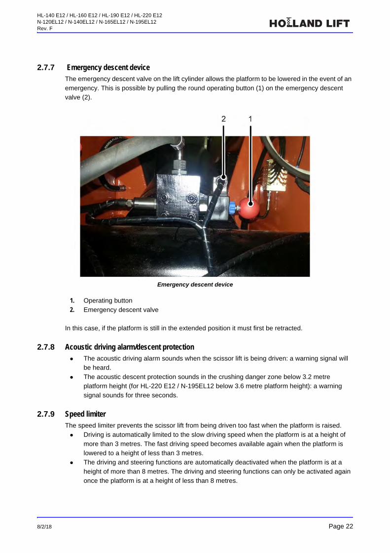
2.7.7 Emergency descent deviceThe emergency descent valve on the lift cylinder allows the platform to be lowered in the event of an
emergency. This is possible by pulling the round operating button (1) on the emergency descent
valve (2).
Emergency descent device
1. Operating button
2. Emergency descent valve
In this case, if the platform is still in the extended position it must first be retracted.
2.7.8 Acoustic driving alarm/descent protection The acoustic driving alarm sounds when the scissor lift is being driven: a warning signal will
be heard.
The acoustic descent protection sounds in the crushing danger zone below 3.2 metre
platform height (for HL-220 E12 / N-195EL12 below 3.6 metre platform height): a warning
signal sounds for three seconds.
2.7.9 Speed limiterThe speed limiter prevents the scissor lift from being driven too fast when the platform is raised.
Driving is automatically limited to the slow driving speed when the platform is at a height of
more than 3 metres. The fast driving speed becomes available again when the platform is
lowered to a height of less than 3 metres.
The driving and steering functions are automatically deactivated when the platform is at a
height of more than 8 metres. The driving and steering functions can only be activated again
once the platform is at a height of less than 8 metres.
HL-140 E12 / HL-160 E12 / HL-190 E12 / HL-220 E12N-120EL12 / N-140EL12 / N-165EL12 / N-195EL12Rev. F
Page 23 8/2/18
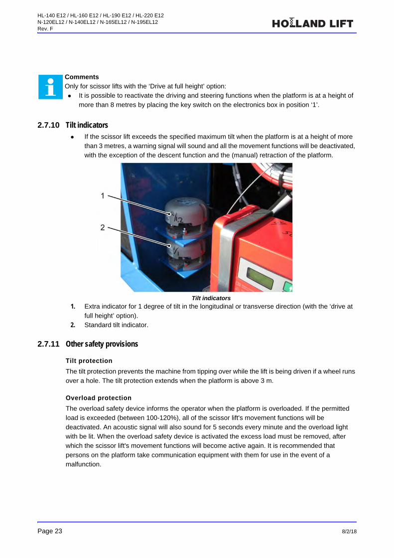
2.7.10 Tilt indicators If the scissor lift exceeds the specified maximum tilt when the platform is at a height of more
than 3 metres, a warning signal will sound and all the movement functions will be deactivated,
with the exception of the descent function and the (manual) retraction of the platform.
Tilt indicators
1. Extra indicator for 1 degree of tilt in the longitudinal or transverse direction (with the ‘drive at
full height’ option).
2. Standard tilt indicator.
2.7.11 Other safety provisions
Tilt protection
The tilt protection prevents the machine from tipping over while the lift is being driven if a wheel runs
over a hole. The tilt protection extends when the platform is above 3 m.
Overload protection
The overload safety device informs the operator when the platform is overloaded. If the permitted
load is exceeded (between 100-120%), all of the scissor lift's movement functions will be
deactivated. An acoustic signal will also sound for 5 seconds every minute and the overload light
with be lit. When the overload safety device is activated the excess load must be removed, after
which the scissor lift's movement functions will become active again. It is recommended that
persons on the platform take communication equipment with them for use in the event of a
malfunction.
Comments
Only for scissor lifts with the ‘Drive at full height’ option:
It is possible to reactivate the driving and steering functions when the platform is at a height of
more than 8 metres by placing the key switch on the electronics box in position ‘1’.

HL-140 E12 / HL-160 E12 / HL-190 E12 / HL-220 E12N-120EL12 / N-140EL12 / N-165EL12 / N-195EL12Rev. F
8/2/18 Page 24
Lift cylinder protection device
This protection device prevents the lift cylinder from becoming mechanically jammed. A limit
switch is activated by a switch cam just before the cylinder reaches its maximum range, so
that the lift cylinder stops in time.
Limit switches and switch cams
1. 3.2-metre switch (3.6 metres for HL-220 E12 / N-195EL12)
2. Limit switch
3. 8-metre switch
Pipe/hose rupture safety device
An electrically controlled valve is fitted on the lift cylinder. It is only possible to lower the platform with
a control signal from the control box, even in the event of a line/hose rupture.
The maximum descent speed is limited by an orifice (constriction) in the cylinder.
Battery charge protection
The charge protection prevents use of the machine during battery charging.
The charge protection switches off all machine functions during battery charging.
The LEDs on the control box flash sequentially to indicate this.
HL-140 E12 / HL-160 E12 / HL-190 E12 / HL-220 E12N-120EL12 / N-140EL12 / N-165EL12 / N-195EL12Rev. F
Page 25 8/2/18
Driving on inclines
Before driving the scissor lift up an incline, the selection switch for driving speed must be put in
position ‘0’ (slow driving). When driving up an incline with a gradient of up to 25%, the platform must
be in the lowest position and no sudden steering manoeuvres may be made. The scissor lift may
only be driven up or down – never across! – an incline. The scissor lift may only be rolled up and
down inclines with a gradient above 25% through use of a reliable winch! When doing so, consider
the weight of the scissor lift (see chapter ‘Technical specifications’).
Battery state-of-charge meter
The battery state-of-charge meter has a LED bar indicator that shows the battery's current state of
charge.
When all of the LED segments are on, the battery is fully charged.
The fewer LEDs that are lit, the less charge remaining in the battery.
See section ‘Battery state-of-charge meter’.
Descent protection
The models are equipped with descent protection. During descent the descending movement is
interrupted at a height of 3.2 metres (3.6 metres for HL-220 E12 / N-195EL12). To resume the
descending movement the decent control must be released and engaged again; descent will
resume after 3 seconds. During descent the acoustic and visual descent protection are active. The
descent speed will not exceed 0.2 m/s.
HL-140 E12 / HL-160 E12 / HL-190 E12 / HL-220 E12N-120EL12 / N-140EL12 / N-165EL12 / N-195EL12Rev. F
8/2/18 Page 26
3 Controls
3.1 Overview
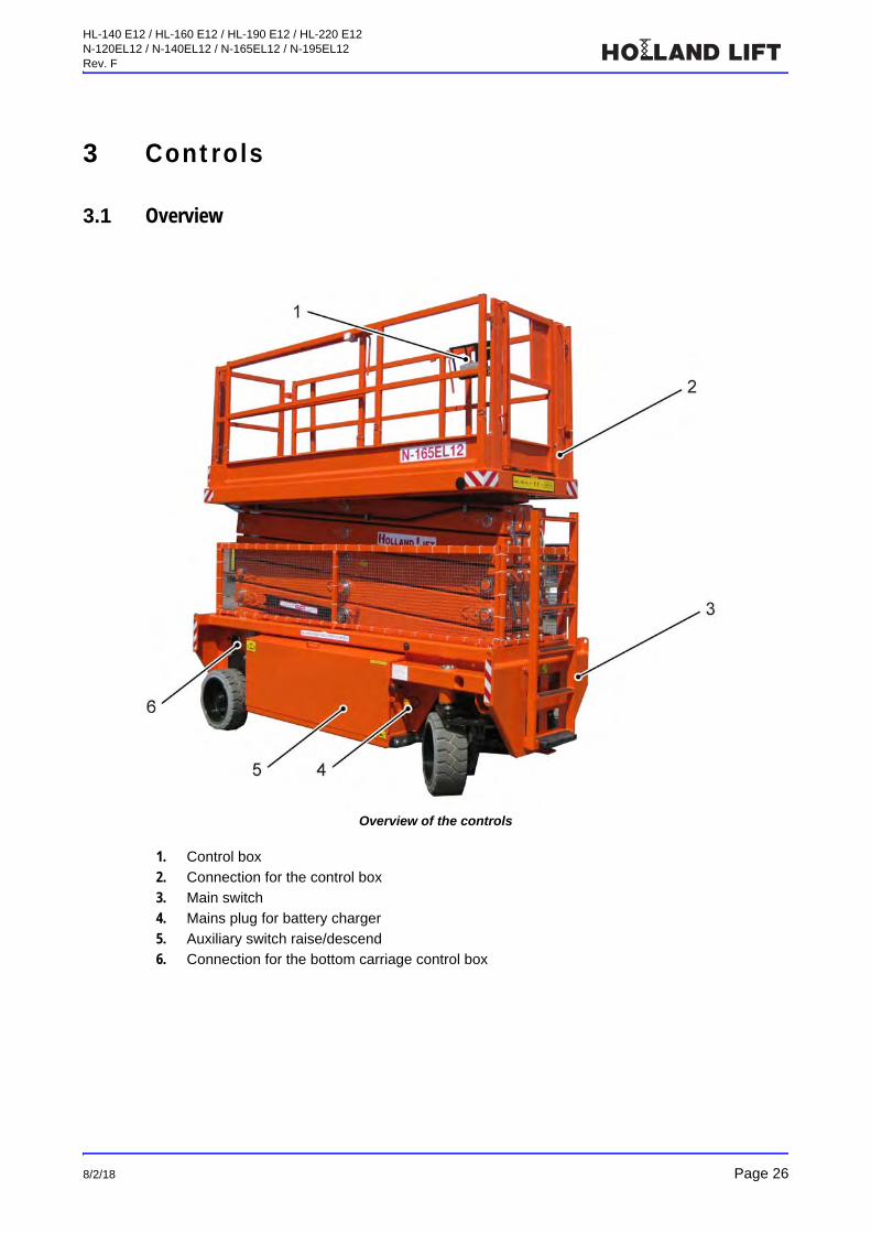
Overview of the controls
1. Control box
2. Connection for the control box
3. Main switch
4. Mains plug for battery charger
5. Auxiliary switch raise/descend
6. Connection for the bottom carriage control box
HL-140 E12 / HL-160 E12 / HL-190 E12 / HL-220 E12N-120EL12 / N-140EL12 / N-165EL12 / N-195EL12Rev. F
Page 27 8/2/18
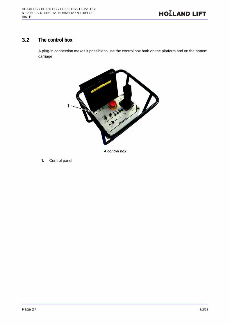
3.2 The control box
A plug-in connection makes it possible to use the control box both on the platform and on the bottom
carriage.
A control box
1. Control panel

HL-140 E12 / HL-160 E12 / HL-190 E12 / HL-220 E12N-120EL12 / N-140EL12 / N-165EL12 / N-195EL12Rev. F
8/2/18 Page 28
3.2.1 The control panel
Controls on the control box
1. Emergency stop button
2. Forwards/backwards control handle
3. Dead man's switch
4. Steer to the left
5. Steer to the right
6. Indicator light ‘battery voltage too low’
7. Indicator light for tilt
8. Indicator light for overload
9. Indicator light for central grease lubrication system (option)
10. Driving speed fast/slow
11. Horn/Differential lock
12. Raise/descend
EMERGEN
CY
E
MERGENCY EMERGENCY
53 41 2
12
10
9 8
11
7 6
HL-140 E12 / HL-160 E12 / HL-190 E12 / HL-220 E12N-120EL12 / N-140EL12 / N-165EL12 / N-195EL12Rev. F
Page 29 8/2/18
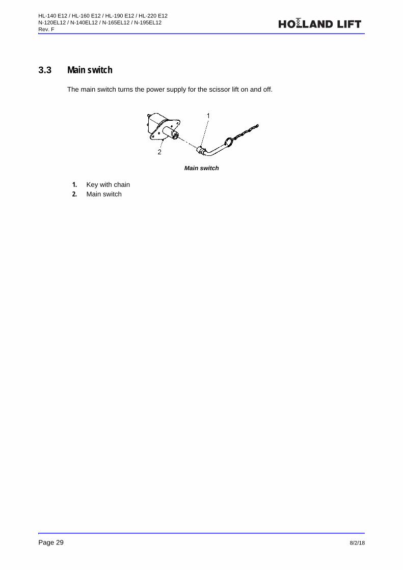
3.3 Main switch
The main switch turns the power supply for the scissor lift on and off.
Main switch
1. Key with chain
2. Main switch
HL-140 E12 / HL-160 E12 / HL-190 E12 / HL-220 E12N-120EL12 / N-140EL12 / N-165EL12 / N-195EL12Rev. F
8/2/18 Page 30
4 Machine compartments
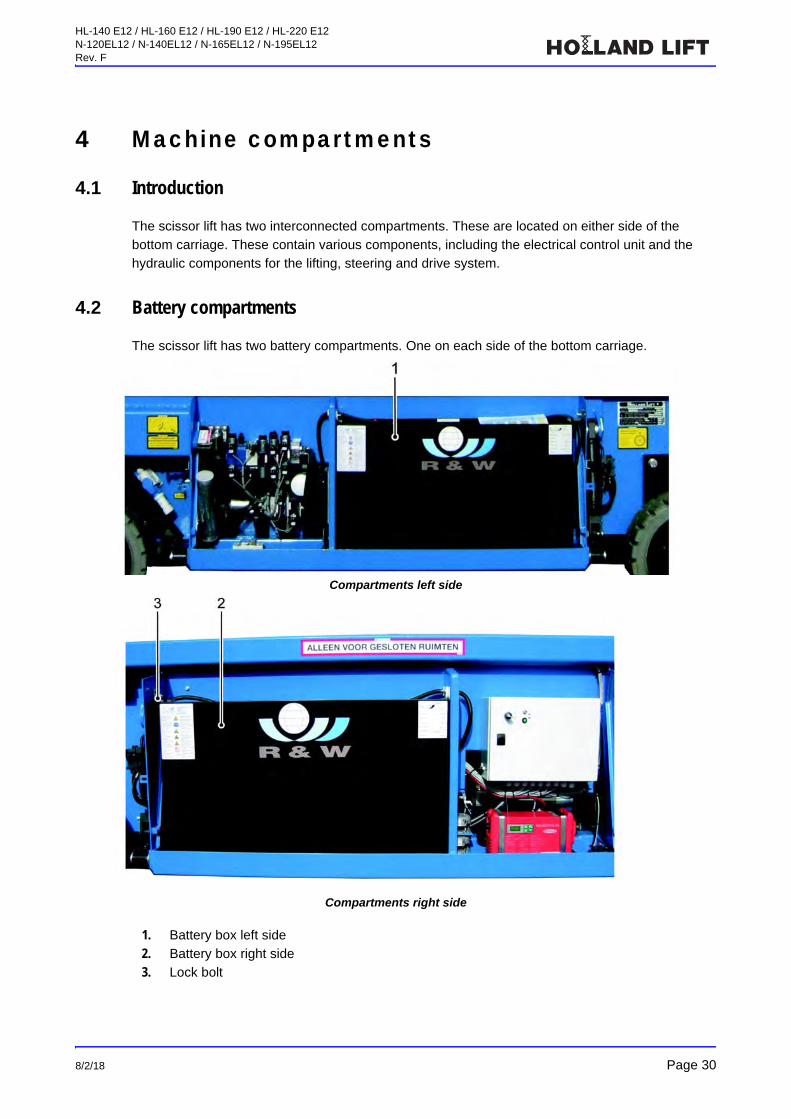
4.1 Introduction
The scissor lift has two interconnected compartments. These are located on either side of the
bottom carriage. These contain various components, including the electrical control unit and the
hydraulic components for the lifting, steering and drive system.
4.2 Battery compartments
The scissor lift has two battery compartments. One on each side of the bottom carriage.
Compartments left side
Compartments right side
1. Battery box left side
2. Battery box right side
3. Lock bolt

HL-140 E12 / HL-160 E12 / HL-190 E12 / HL-220 E12N-120EL12 / N-140EL12 / N-165EL12 / N-195EL12Rev. F
Page 31 8/2/18
4.3 Electrical box
This compartment contains the electrical control unit.
Electrical compartment
1. Key switch for overload protection2. Angle sensor calibration – store
3. Angle sensor calibration – save
4. PLC
5. Control current fuses (see the electrical diagram for the relevant circuits).

HL-140 E12 / HL-160 E12 / HL-190 E12 / HL-220 E12N-120EL12 / N-140EL12 / N-165EL12 / N-195EL12Rev. F
8/2/18 Page 32
4.4 Hydraulic oil compartment
Hydraulic oil compartment
The hydraulic oil tank is located on the right side of the bottom carriage.
1. Fill opening – hydraulic oil tank
2. Main circuit breakers
3. Primary manifold
4. Hydraulic oil filter
5. Motor controller
6. Inverter 48/24V
7. Hydraulic tank
8. Driving manifold
9. Electric motors with pumps
10. Main relay
11. Limit switch for tilt protection
12. Document tube

HL-140 E12 / HL-160 E12 / HL-190 E12 / HL-220 E12N-120EL12 / N-140EL12 / N-165EL12 / N-195EL12Rev. F
Page 33 8/2/18
4.5 Auxiliary switch raise/descend
In the hydraulic cabinet, on the electrical box, there is an auxiliary (self-centring) toggle switch for
raising and lowering the platform. This switch can be used during maintenance and in emergency
situations.
Auxiliary switch raise/descend
1. Auxiliary switch raise/descend
4.6 Mains plug for battery charger
The mains power plug for the battery charger is located in a plug holder on the side of the battery
cabinet. The mains power plug may only be connected to a Schuko-type mains socket.
Mains plug for battery charger
1. Mains plug for battery charger

HL-140 E12 / HL-160 E12 / HL-190 E12 / HL-220 E12N-120EL12 / N-140EL12 / N-165EL12 / N-195EL12Rev. F
8/2/18 Page 34
5 Normal use
5.1 Preparations before use
See the instruction manual for the power source for instructions on how to prepare the scissor lift.
5.2 Starting
A. Insert the key (1) into the main switch.
B. Turn the key a quarter turn clockwise.
• The power for the scissor lift is now ‘on’.
Main switch and key
C. Access the platform via the steps.
D. Erect the guardrail sections in the correct position and secure them correctly (see photos).
Linchpin for platform guardrail section

HL-140 E12 / HL-160 E12 / HL-190 E12 / HL-220 E12N-120EL12 / N-140EL12 / N-165EL12 / N-195EL12Rev. F
Page 35 8/2/18
Linchpin for platform guardrail section
Linchpin for platform guardrail section

HL-140 E12 / HL-160 E12 / HL-190 E12 / HL-220 E12N-120EL12 / N-140EL12 / N-165EL12 / N-195EL12Rev. F
8/2/18 Page 36
Linchpin(s) on the platform
E. Check whether the control box has been connected correctly.
F. Pull out and rotate the emergency stop button.
The scissor lift activates the tilt protection for 10 seconds (when height is below 4 metres).Once the warning signal is off, you can operate the scissor lift with the control box.
5.3 Switching off
1. Retract the platform manually (if necessary).
2. Lower the platform.
3. Press the emergency stop button.
4. Disconnect the control box and store it safely.
5. Turn the key in the main switch a quarter turn anticlockwise.
6. Remove the key from the main switch.
5.4 Platform during transport
If the platform guardrails were folded down during transport, it is necessary to make sure they are
fitted correctly, including the linchpins, before the scissor lift is used again.
Note!
Never use the scissor lift if the linchpins are not all fitted.
The guardrail sections may never be removed when using the scissor lift.
The platform must be completely retracted and secured during transport.

HL-140 E12 / HL-160 E12 / HL-190 E12 / HL-220 E12N-120EL12 / N-140EL12 / N-165EL12 / N-195EL12Rev. F
Page 37 8/2/18
Linchpin for the extendable platform
5.5 Battery state-of-charge meter
The battery state-of-charge meter (1) is located on the right side of the bottom carriage.
Location of the battery state-of-charge meter
1. battery state-of-charge meter
HL-140 E12 / HL-160 E12 / HL-190 E12 / HL-220 E12N-120EL12 / N-140EL12 / N-165EL12 / N-195EL12Rev. F
8/2/18 Page 38
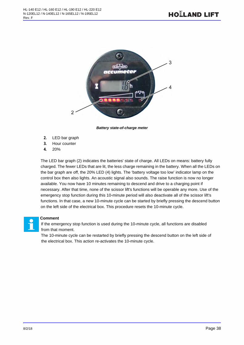
Battery state-of-charge meter
2. LED bar graph
3. Hour counter
4. 20%
The LED bar graph (2) indicates the batteries' state of charge. All LEDs on means: battery fully
charged. The fewer LEDs that are lit, the less charge remaining in the battery. When all the LEDs on
the bar graph are off, the 20% LED (4) lights. The ‘battery voltage too low’ indicator lamp on the
control box then also lights. An acoustic signal also sounds. The raise function is now no longer
available. You now have 10 minutes remaining to descend and drive to a charging point if
necessary. After that time, none of the scissor lift's functions will be operable any more. Use of the
emergency stop function during this 10-minute period will also deactivate all of the scissor lift's
functions. In that case, a new 10-minute cycle can be started by briefly pressing the descend button
on the left side of the electrical box. This procedure resets the 10-minute cycle.
Comment
If the emergency stop function is used during the 10-minute cycle, all functions are disabled
from that moment.
The 10-minute cycle can be restarted by briefly pressing the descend button on the left side of
the electrical box. This action re-activates the 10-minute cycle.

HL-140 E12 / HL-160 E12 / HL-190 E12 / HL-220 E12N-120EL12 / N-140EL12 / N-165EL12 / N-195EL12Rev. F
Page 39 8/2/18
6 Transport
6.1 Towing
6.1.1 IntroductionThe scissor lift has multiple disc brakes with a towing function. The multiple disc brakes are applied
when the scissor lift is stationary. All the multiple disc brakes must be released before the scissor lift
can be towed.
Releasing the multiple disc brakes
1. Plug
6.1.2 Releasing the multiple disc brakes
Loosen the central bolt with a 30 mm socket, turning it out ±10-14 mm, until you feel the stop.
Loosen the last turns by hand.
The scissor lift can now be towed, because the wheels are no longer braked.
Warning
Prevent the scissor lift from being able to roll away. For example, place chocks against the wheels.
Note!
Do not continue to turn past the end stop.
Warning
Restore the brakes for all the wheels after towing the scissor lift.
HL-140 E12 / HL-160 E12 / HL-190 E12 / HL-220 E12N-120EL12 / N-140EL12 / N-165EL12 / N-195EL12Rev. F
8/2/18 Page 40
6.1.3 Point of special interestWhen towing the scissor lift, pay attention to the following:
The scissor lift may never be towed at a speed faster than the scissor lift's maximum speed.
6.2 Transport
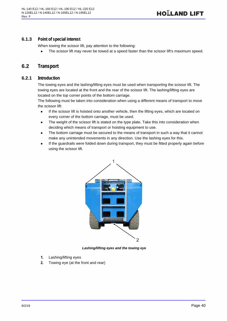
6.2.1 IntroductionThe towing eyes and the lashing/lifting eyes must be used when transporting the scissor lift. The
towing eyes are located at the front and the rear of the scissor lift. The lashing/lifting eyes are
located on the top corner points of the bottom carriage.
The following must be taken into consideration when using a different means of transport to move
the scissor lift:
If the scissor lift is hoisted onto another vehicle, then the lifting eyes, which are located on
every corner of the bottom carriage, must be used.
The weight of the scissor lift is stated on the type plate. Take this into consideration when
deciding which means of transport or hoisting equipment to use.
The bottom carriage must be secured to the means of transport in such a way that it cannot
make any unintended movements in any direction. Use the lashing eyes for this.
If the guardrails were folded down during transport, they must be fitted properly again before
using the scissor lift.
Lashing/lifting eyes and the towing eye
1. Lashing/lifting eyes
2. Towing eye (at the front and rear)
HL-140 E12 / HL-160 E12 / HL-190 E12 / HL-220 E12N-120EL12 / N-140EL12 / N-165EL12 / N-195EL12Rev. F
Page 41 8/2/18
6.2.2 Preparation1. Check the scissor lift's brakes.
2. Slide the platform in and secure it with the transport linchpin.
6.2.3 Points of attentionWhen transporting the scissor lift, pay attention to the following:
If the incline is steeper than 25%, use a winch to pull the scissor lift onto the means of
transport. Secure the winch cable to the towing eye on the bottom carriage.
Only use the lashing/lifting eyes on the corners of the bottom carriage to hoist the scissor lift.
Note!
Read the chapter entitled ‘Safety’ for more information concerning safety issues when transporting
the scissor lift.
Comment
HOLLAND LIFT INTERNATIONAL B.V. recommends that the scissor lift only be hoisted using a
special hoisting tool. If necessary, contact the manufacturer for more information.

HL-140 E12 / HL-160 E12 / HL-190 E12 / HL-220 E12N-120EL12 / N-140EL12 / N-165EL12 / N-195EL12Rev. F
8/2/18 Page 42
7 Maintenance
7.1 Maintenance overview
Comment
The maintenance intervals given below are based on normal use of the scissor lift under normal
conditions.
If the scissor lift is subjected to extreme conditions (such as dust, algae, bacteria or salt
deposits), the frequency must be increased.
We rely on your sense of responsibility and professionalism.
Component Action Frequency
Scissor lift Check the entire scissor lift for damage. Every day
Check for correct operation. Every day
Make sure the safety provisions work correctly. Every day
Make sure the decals are legible. If necessary, replace
them.
Every day
Lubricate the scissor lift according to the lubrication
diagram.
Once a month
Check all the bolt connections. If necessary, tighten. Once every
3 months
Check the maximum permitted lifting pressure at the
maximum working load and maximum driving
pressure. If the measured maximum permitted lifting
pressure is greater than the stated maximum driving
pressure: contact the manufacturer.
Once every
3 months
Check all the sealed settings. If there are broken seals: contact the manufacturer.
Once every
3 months
Have the scissor lift inspected by an expert. Once a year
Scissor mechanism Check that all parts are correctly attached and
secured.
Once every
3 months
Have the scissor mechanism inspected by an expert. Every 5 years
Lift cylinder Check that all parts are correctly attached and
secured.
Once every
3 months
Hydraulic system Check for damage and leaks. If necessary, rectify
leaks and damage.
Every day
Check oil reservoir. If necessary, top up. Every week
Replace the filter element. Once every
3 months
Change the oil. Once a year
HL-140 E12 / HL-160 E12 / HL-190 E12 / HL-220 E12N-120EL12 / N-140EL12 / N-165EL12 / N-195EL12Rev. F
Page 43 8/2/18
7.1.1 Protective guardrailThe protective guardrail on the bottom carriage prevents body parts from becoming trapped by the
moving scissor arms.
Batteries Check fluid levels. Top up if necessary. Every week
Recharge the battery if the scissor lift has not been
used for more than 2 weeks.
Every two weeks
when not in use
Limit switches for height
stops
Check operation and adjustment. Every week
Tilt safety device Make sure it works correctly. Once every
3 months
Wheels Tighten the wheel bolts according to the tightening
torque chart.
Once every
3 months
Raise the wheels off the ground if the scissor lift is not
going to be used for a long period of time.
-
PLC operation Replace batteries. Only do so while the PLC is
connected to a power supply, so the program in the
memory will not be lost.
Every 4 years
Electric motors Check the carbon brushes for wear. Replace if
necessary, and clean the collector.
Once every
3 months
Note!
If the guardrail is removed during maintenance work, it must be reinstalled correctly once the
maintenance work has been completed.
It is not permitted to use the scissor lift when the protective guardrail is not fitted or does not work as
intended.
The protective guardrail must be removed before lubrication.
Make sure the guardrail is properly installed before the scissor lift is used again.
Component Action Frequency
HL-140 E12 / HL-160 E12 / HL-190 E12 / HL-220 E12N-120EL12 / N-140EL12 / N-165EL12 / N-195EL12Rev. F
8/2/18 Page 44
7.2 Overviews
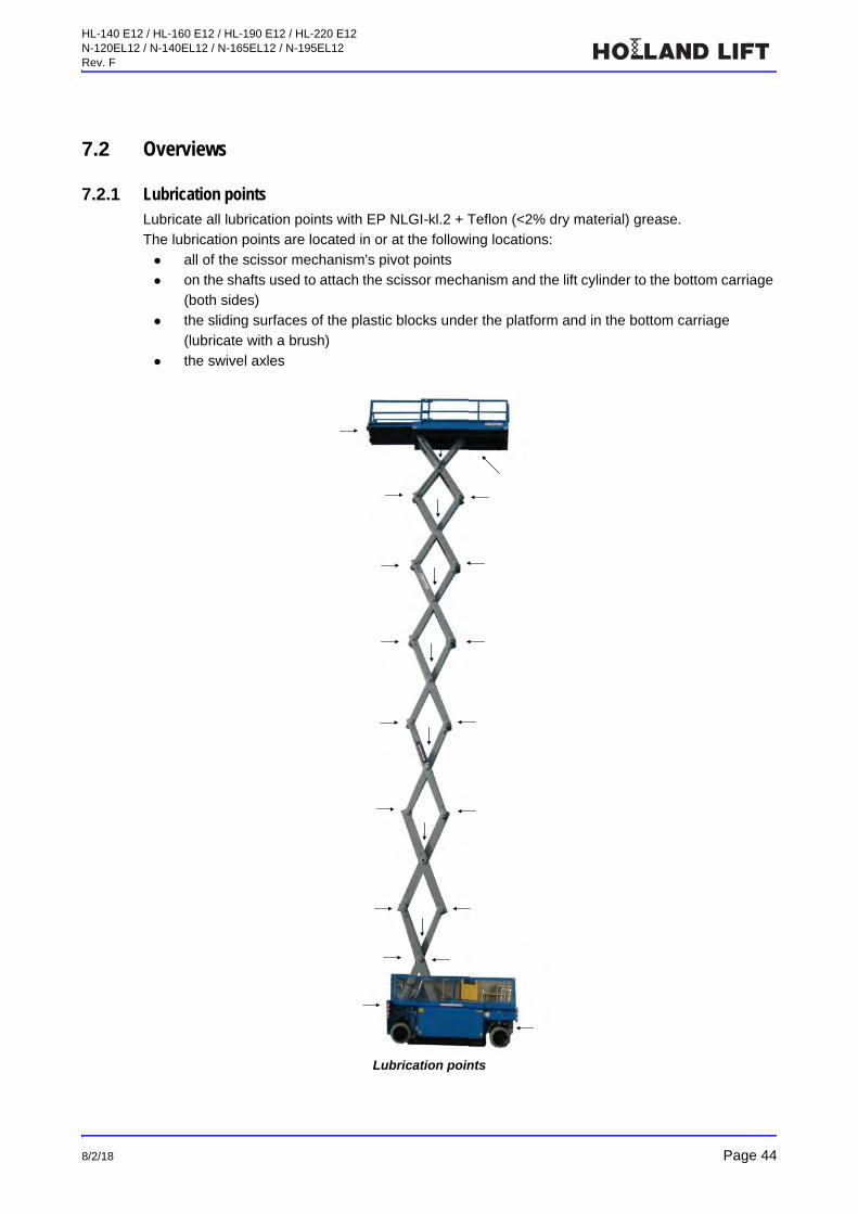
7.2.1 Lubrication pointsLubricate all lubrication points with EP NLGI-kl.2 + Teflon (<2% dry material) grease.
The lubrication points are located in or at the following locations:
all of the scissor mechanism's pivot points
on the shafts used to attach the scissor mechanism and the lift cylinder to the bottom carriage
(both sides)
the sliding surfaces of the plastic blocks under the platform and in the bottom carriage
(lubricate with a brush)
the swivel axles
Lubrication points

HL-140 E12 / HL-160 E12 / HL-190 E12 / HL-220 E12N-120EL12 / N-140EL12 / N-165EL12 / N-195EL12Rev. F
Page 45 8/2/18
7.2.2 Tightening torques
7.3 Maintenance procedures
7.3.1 Installing and removing the safety props
Introduction
The safety prop prevents people from becoming trapped in the scissor mechanism when carrying
out work on the scissor lift.
Safety prop
1. Safety prop
2. Stub shaft
3. Stop
4. Latch
Bolt connection Tightening torque Thread
Tracking rod on steering knuckle 50 Nm M16
Steering cylinder on tracking rod 50 Nm M16
Steering cylinder on bottom carriage 50 Nm M10
Rear axle of bottom carriage 725 Nm M24
Wheel nuts 250 Nm M18x1.5
Gearbox at swivel axles 200 Nm M16
HL-140 E12 / HL-160 E12 / HL-190 E12 / HL-220 E12N-120EL12 / N-140EL12 / N-165EL12 / N-195EL12Rev. F
8/2/18 Page 46
Engaging the safety prop
1. Make sure there is no load on the platform.
2. Make sure the scissor mechanism is opened far enough so that the safety prop (1) can be
engaged.
3. Remove the lock bolt (4).
4. Lift the safety prop (1) out of the retainer and rotate it a quarter turn upwards as far as the
stop (3).
5. Lower the platform until the stub shaft (2) falls into the recess in the safety prop.
Disengaging the safety prop
1. Raise the scissor mechanism slightly to release the safety prop.
2. Swing the safety prop a quarter turn back into the storage position.
3. Lower the safety prop into the retainer.
7.3.2 Topping up the hydraulic system
Fill the tank until the oil level reaches half the volume indicated on the gauge glass.
7.3.3 Lubrication
1. Engage the safety prop.
2. Manually pump the correct quantity of grease into all the indicated lubrication points until
plenty of grease escapes from behind the washers.
3. Carefully remove any excess grease.
7.3.4 Check the tilt safety device Press the tilt safety device in both the longitudinal and transverse direction.
• A warning signal will sound.
Note!
First disconnect the interconnection hose (on top of the tank) between the two tanks so the air
can exit the tank.
Note!
Only top up the hydraulic system with TOTAL Equivis ZS 32.
Note!
Only use EP NLGI-kl.2 + Teflon (< 2% dry material) grease to lubricate the scissor lift. The warranty will be void if a different type of grease is used.
HL-140 E12 / HL-160 E12 / HL-190 E12 / HL-220 E12N-120EL12 / N-140EL12 / N-165EL12 / N-195EL12Rev. F
Page 47 8/2/18
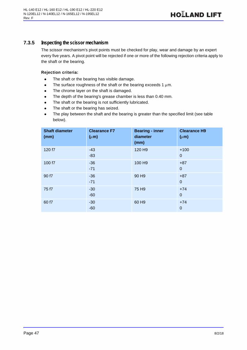
7.3.5 Inspecting the scissor mechanismThe scissor mechanism's pivot points must be checked for play, wear and damage by an expert
every five years. A pivot point will be rejected if one or more of the following rejection criteria apply to
the shaft or the bearing.
Rejection criteria:
The shaft or the bearing has visible damage.
The surface roughness of the shaft or the bearing exceeds 1 m.
The chrome layer on the shaft is damaged.
The depth of the bearing's grease chamber is less than 0.40 mm.
The shaft or the bearing is not sufficiently lubricated.
The shaft or the bearing has seized.
The play between the shaft and the bearing is greater than the specified limit (see table
below).
Shaft diameter(mm)
Clearance F7(m)
Bearing - inner
diameter(mm)
Clearance H9(m)
120 f7 -43
-83
120 H9 +100
0
100 f7 -36
-71
100 H9 +87
0
90 f7 -36
-71
90 H9 +87
0
75 f7 -30
-60
75 H9 +74
0
60 f7 -30
-60
60 H9 +74
0

HL-140 E12 / HL-160 E12 / HL-190 E12 / HL-220 E12N-120EL12 / N-140EL12 / N-165EL12 / N-195EL12Rev. F
8/2/18 Page 48
8 Troubleshooting
Problem Possible cause Action
The scissor lift cannot be turned
on.
The main switch has not been
turned on.
Turn on the main switch.
The emergency stop button has
been pressed.
Pull out the emergency stop
button and wait 10 seconds.
There is a short circuit or a fuse
has blown.
Determine the cause and replace
the fuse.
The red segments of the LED bar
indicator are flashing.
The battery voltage is too low. Charge the batteries.
The hydraulic pump motor runs,
but the scissor lift does not
function.
The hydraulic pump does not
work, so the hydraulic system
cannot build up any pressure.
Contact the technical service
department.
The oil level in the hydraulic
system is too low.
Top up the hydraulic system.
The hydraulic pump is broken. Replace the hydraulic pump.
The scissor lift cannot be driven
with a raised platform or the
platform cannot be raised.
The maximum tilt has been
exceeded and the tilt safety
device has been activated.
Lower the platform and make
sure the scissor lift is on a level
surface.
The platform cannot be raised or
lowered.
The platform has been
overloaded and the overload
safety device has been activated.
Reduce the load on the platform.
Or follow the emergency descent
procedure.
The scissor lift cannot be driven
at the fast speed.
The platform is at a height of
more than 3 metres.
Lower the platform to a height of
less than 3 metres.
The scissor lift cannot be driven. The platform is at a height of
more than 8 metres.
Lower the platform to a height of
less than 8 metres.
The scissor lift brakes do not
engage.
The brake system was not re-
engaged after towing.
Re-engage the brake system.
The brake packet is not correctly
adjusted.
Readjust the brake packet.
The multiple disc brake is worn. Fit a new brake packet.
The platform cannot be lowered. The safety prop is blocking the
scissor mechanism.
Disengage the safety prop.
The electrical system has cut out. Use the emergency descent
valve to lower the platform and
check the electrical system.
A problem keeps recurring. Contact the manufacturer
(Holland Lift International B.V.).

HL-140 E12 / HL-160 E12 / HL-190 E12 / HL-220 E12N-120EL12 / N-140EL12 / N-165EL12 / N-195EL12Rev. F
Page 49 8/2/18
9 Disposal
9.1 Introduction
The scissor lift must be disposed of in an environmentally-friendly manner. For example:
trade in the scissor lift when purchasing a new scissor lift
take the scissor lift to a specialised waste disposal company
9.2 Disposal procedure
1. Remove the batteries.
2. Remove the oil from the hydraulic system.
3. If necessary, remove the parts that can be reused.
4. For disposal of the batteries, oil and parts that cannot be reused, contact specialised waste
disposal companies.
HL-140 E12 / HL-160 E12 / HL-190 E12 / HL-220 E12N-120EL12 / N-140EL12 / N-165EL12 / N-195EL12Rev. F
8/2/18 Page 50
10 Technical specifications
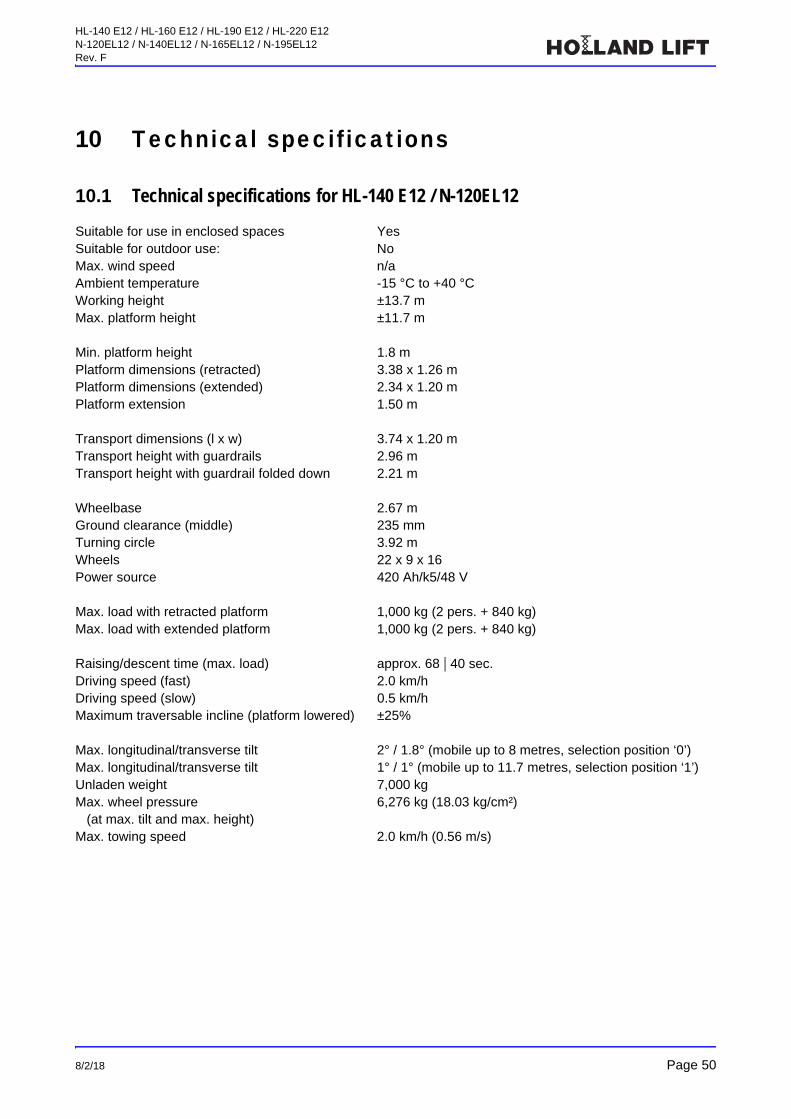
10.1 Technical specifications for HL-140 E12 / N-120EL12
Suitable for use in enclosed spaces YesSuitable for outdoor use: NoMax. wind speed n/aAmbient temperature -15 °C to +40 °CWorking height ±13.7 mMax. platform height ±11.7 m
Min. platform height 1.8 mPlatform dimensions (retracted) 3.38 x 1.26 mPlatform dimensions (extended) 2.34 x 1.20 mPlatform extension 1.50 m
Transport dimensions (l x w) 3.74 x 1.20 mTransport height with guardrails 2.96 mTransport height with guardrail folded down 2.21 m
Wheelbase 2.67 mGround clearance (middle) 235 mmTurning circle 3.92 mWheels 22 x 9 x 16Power source 420 Ah/k5/48 V
Max. load with retracted platform 1,000 kg (2 pers. + 840 kg)Max. load with extended platform 1,000 kg (2 pers. + 840 kg)
Raising/descent time (max. load) approx. 68 | 40 sec. Driving speed (fast) 2.0 km/hDriving speed (slow) 0.5 km/hMaximum traversable incline (platform lowered) ±25%
Max. longitudinal/transverse tilt 2° / 1.8° (mobile up to 8 metres, selection position ‘0’)Max. longitudinal/transverse tilt 1° / 1° (mobile up to 11.7 metres, selection position ‘1’)Unladen weight 7,000 kgMax. wheel pressure
(at max. tilt and max. height)6,276 kg (18.03 kg/cm²)
Max. towing speed 2.0 km/h (0.56 m/s)

HL-140 E12 / HL-160 E12 / HL-190 E12 / HL-220 E12N-120EL12 / N-140EL12 / N-165EL12 / N-195EL12Rev. F
Page 51 8/2/18
10.2 Technical specifications for HL-160 E12 / N-140EL12
Suitable for use in enclosed spaces YesSuitable for outdoor use: NoMax. wind speed n/aAmbient temperature -15 °C to +40 °CWorking height ±16.0 mMax. platform height ±14.0 m
Min. platform height 2.02 mPlatform dimensions (retracted) 3.38 x 1.16 mPlatform dimensions (extended) 4.88 x 1.16 mPlatform extension 1.50 m
Transport dimensions (l x w) 3.74 x 1.20 mTransport height with guardrails 3.18 mTransport height with guardrail folded down 2.43 m
Wheelbase 2.67 mGround clearance (middle) 235 mmTurning circle 3.92 mWheels 22 x 9 x 16Power source 420 Ah/k5/48 V
Max. load with retracted platform 750 kg (2 pers. + 590 kg)Max. load with extended platform 750 kg (2 pers. + 590 kg)
Raising/descent time (max. load) approx. 70 | 45 sec. Driving speed (fast) 2.0 km/hDriving speed (slow) 0.5 km/hMaximum traversable incline (platform lowered) ±25%
Max. longitudinal/transverse tilt 2° / 1.8° (mobile up to 8 metres, selection position ‘0’)Max. longitudinal/transverse tilt 1° / 1° (mobile up to 14 metres, selection position ‘1’)Unladen weight 7,550 kgMax. wheel pressure
(at max. tilt and max. height)6,500 kg (18.68 kg/cm²)
Max. towing speed 2.0 km/h (0.56 m/s)
HL-140 E12 / HL-160 E12 / HL-190 E12 / HL-220 E12N-120EL12 / N-140EL12 / N-165EL12 / N-195EL12Rev. F
8/2/18 Page 52
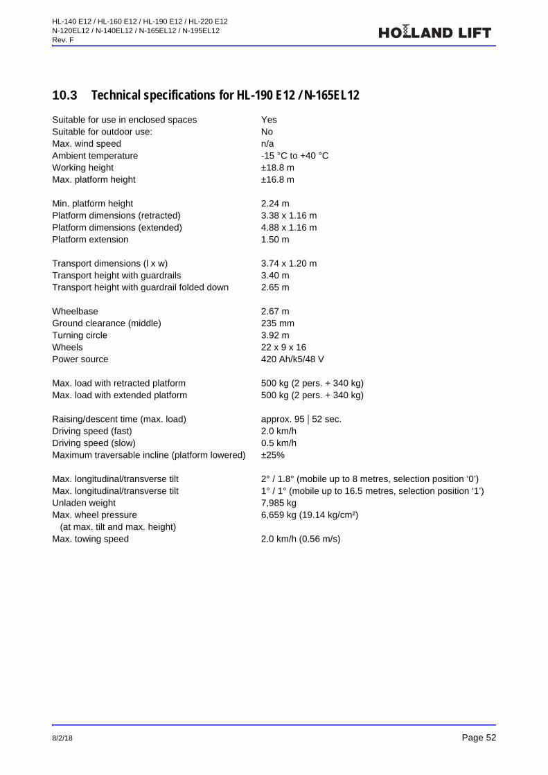
10.3 Technical specifications for HL-190 E12 / N-165EL12
Suitable for use in enclosed spaces YesSuitable for outdoor use: NoMax. wind speed n/aAmbient temperature -15 °C to +40 °CWorking height ±18.8 mMax. platform height ±16.8 m
Min. platform height 2.24 mPlatform dimensions (retracted) 3.38 x 1.16 mPlatform dimensions (extended) 4.88 x 1.16 mPlatform extension 1.50 m
Transport dimensions (l x w) 3.74 x 1.20 mTransport height with guardrails 3.40 mTransport height with guardrail folded down 2.65 m
Wheelbase 2.67 mGround clearance (middle) 235 mmTurning circle 3.92 mWheels 22 x 9 x 16Power source 420 Ah/k5/48 V
Max. load with retracted platform 500 kg (2 pers. + 340 kg)Max. load with extended platform 500 kg (2 pers. + 340 kg)
Raising/descent time (max. load) approx. 95 | 52 sec. Driving speed (fast) 2.0 km/hDriving speed (slow) 0.5 km/hMaximum traversable incline (platform lowered) ±25%
Max. longitudinal/transverse tilt 2° / 1.8° (mobile up to 8 metres, selection position ‘0’)Max. longitudinal/transverse tilt 1° / 1° (mobile up to 16.5 metres, selection position ‘1’)Unladen weight 7,985 kgMax. wheel pressure
(at max. tilt and max. height)6,659 kg (19.14 kg/cm²)
Max. towing speed 2.0 km/h (0.56 m/s)

HL-140 E12 / HL-160 E12 / HL-190 E12 / HL-220 E12N-120EL12 / N-140EL12 / N-165EL12 / N-195EL12Rev. F
Page 53 8/2/18
10.4 Technical specifications for HL-220 E12 / N-195EL12
Suitable for use in enclosed spaces YesSuitable for outdoor use: NoMax. wind speed n/aAmbient temperature -15 °C to +40 °CWorking height ±21.7 mMax. platform height ±19.7 m
Min. platform height 2.58 mPlatform dimensions (retracted) 3.38 x 1.16 mPlatform dimensions (extended) 4.88 x 1.16 mPlatform extension 1.50 m
Transport dimensions (l x w) 3.74 x 1.20 mTransport height with guardrails 3.74 mTransport height with guardrail folded down 3.01 m
Wheelbase 2.67 mGround clearance (middle) 235 mmTurning circle 3.92 mWheels 22 x 9 x 16Power source 500 Ah/k5/48 V
Max. load with retracted platform 500 kg (2 pers. + 340 kg)Max. load with extended platform 500 kg (2 pers. + 340 kg)
Raising/descent time (max. load) approx. 90 | 55 sec. Driving speed (fast) 2.0 km/hDriving speed (slow) 0.5 km/hMaximum traversable incline (platform lowered) ±25%
Max. longitudinal/transverse tilt 2° / 1.2° (mobile up to 8 metres, selection position ‘0’)Max. longitudinal/transverse tilt 1° / 1° (mobile up to 19.7 metres, selection position ‘1’)Unladen weight 9,220 kgMax. wheel pressure
(at max. tilt and max. height)8,096 kg (23.27 kg/cm²)
Max. towing speed 1.9 km/h (0.53 m/s)

HL-140 E12 / HL-160 E12 / HL-190 E12 / HL-220 E12N-120EL12 / N-140EL12 / N-165EL12 / N-195EL12Rev. F
8/2/18 Page 54
11 EC DeclarationThis EC Declaration applies to scissor lifts produced after 29 January 2015.
EC DECLARATION OF CONFORMITY(In accordance with the Machinery Directive 2006/42/EC, annex II, sub a.)
HOLLAND LIFT INTERNATIONAL B.V.ANODEWEG 11627 LJ, HOORN, THE NETHERLANDS
Declares that:Scissor lift, series NType: HL-140 E12 / HL-160 E12 / HL-190 E12 / HL-220 E12
N-120EL12 / N-140EL12 / N-165EL12 / N-195EL12Machine number: HL140.... / HL160.... / HL190.... / HL220....
N120.... / N140.... / N165.... / N195....
Complies with the stipulations of the Machinery Directive; 2006/42/EC Conforms to the following additional European Directives:
EMC Directive, 2004/108/ECLow Voltage Directive, 2006/95/EC
Conforms to the following harmonised European standards:EN 280:2001+A2:2009, EN-ISO 12100-1:2003, EN-ISO 12100:2010, EN 349:1+A1:2008, EN-ISO 13850:2008, EN-IEC 60204-1:2006+A1:2009, EN-IEC 60529:1 1992+A1:2000, EN-IEC 60947-5-1-2004
Conformity with the requirements laid out in annex I, IV and VII of the Machinery Directive was established during an EC type examination conducted by S.G.S NEDERLAND B.V. (Identity Number: 0608), Malledijk 18, Spijkenisse (The Netherlands). An EC Type examination certificate was issued with the number: 110201/500/001/2835.
HOORN, ......
..........Managing Director
Holland Lift International B.V.Anodeweg 1PO Box 23211620 EH HOORN (THE NETHERLANDS)Telephone : **-31-(0)229-285555Website : www.hollandlift.com