n board adio avigation eceivers -...
TRANSCRIPT

a
TD ESA OB Radio Navigation
Receivers V2-2.doc
D O C U M E N T
document title/ titre du document
EUROPEAN SPACE TECHNOLOGY
HARMONISATION - TECHNICAL DOSSIER
N BOARD ADIO AVIGATION ECEIVERS
prepared by/préparé par A. García-Rodríguez / TEC-ETN . reference/réference TEC-ETN/2007.65 issue/édition 2 revision/révision 2 date of issue/date d’édition 16 April 2008 status/état Document type/type de document Technical Note Distribution/distribution
On board Radio Navigation Receivers
issue 2 revision 2 - 16 April 2008 TEC-ETN/2007.65
page ii of v
A P P R O V A L
Title titre
On board Radio Navigation Receivers issue issue
2 revision revision
2
author auteur
A. García-Rodríguez / TEC-ETN . date date
16 April 2008
approved by approuvé by
JL. Gerner, TEC-ETN R. de Gaudenzi, TEC-ET
date date
16 April 2008 .
C H A N G E L O G
reason for change /raison du changement issue/issue revision/revision date/date
C H A N G E R E C O R D
Issue: 2 Revision: 2
reason for change/raison du changement page(s)/page(s) paragraph(s)/paragraph(s)

On board Radio Navigation Receivers
issue 2 revision 2 - 16 April 2008 TEC-ETN/2007.65
page iii of v
T A B L E O F C O N T E N T S
1 INTRODUCTION ..................................................................................................1 1.1 List of Acronyms ...............................................................................................................................2
2 EXECUTIVE SUMMARY......................................................................................6
3 TECHNOLOGY STATUS OVERVIEW.................................................................8 3.1 Technology Overview........................................................................................................................8 3.2 Areas Covered by this Technology Dossier.......................................................................................9 3.3 Rationale for Harmonisation of the Technology..............................................................................10 3.4 Technology State of the Art .............................................................................................................10
3.4.1 Prototypes, experiments and first receivers .............................................................................10 3.4.2 Technology state-of-the art ......................................................................................................12
3.4.2.1 Single Frequency Space Receivers ......................................................................................12 3.4.2.2 Multiple Frequency Space Receivers...................................................................................14 3.4.2.3 Low Cost Space Receivers Based on COTS Parts...............................................................16 3.4.2.4 Core Technologies ...............................................................................................................17
3.4.2.4.1 RF FE .............................................................................................................................17 3.4.2.4.2 Base-Band Processing....................................................................................................19
3.4.3 State-of-the-Art Summary........................................................................................................21 3.5 Competitiveness and Benchmarking................................................................................................22 3.6 Technology Trend ............................................................................................................................26
3.6.1 General technology trends .......................................................................................................26 3.6.1.1 Multi Constellations / Multi Frequency Receivers. New GNSS signals ............................26 3.6.1.2 Advance Microelectronics. Miniaturisation of Space Qualified GNSS Receivers..............27 3.6.1.3 Software GNSS Receivers ...................................................................................................27 3.6.1.4 New Multipath Mitigation Techniques ................................................................................28 3.6.1.5 Integration with other sensors and systems..........................................................................28 3.6.1.6 Performance improvement. New signal and data processing algorithms ...........................28
3.6.2 Ongoing activities in radio navigation technology in Europe..................................................29 3.6.2.1 GNSS Receivers Modernisation. New GPS and Galileo signals.........................................29 3.6.2.2 Advance Microelectronics. Core Technologies evolutions .................................................30 3.6.2.3 Integrated GNSS Receivers. ................................................................................................30 3.6.2.4 Software GNSS Receivers ...................................................................................................30 3.6.2.5 Multipath Mitigation ............................................................................................................31
3.6.3 Ongoing activities in radio navigation technology Outside Europe ........................................31
4 MISSION NEEDS AND MARKET PERSPECTIVES..........................................33 4.1 Application to Missions. GNSS-based Space Applications.............................................................33
4.1.1 Absolute navigation .................................................................................................................34

On board Radio Navigation Receivers
issue 2 revision 2 - 16 April 2008 TEC-ETN/2007.65
page iv of v
4.1.1.1 Launchers .............................................................................................................................34 4.1.1.2 Re-entry navigation..............................................................................................................34 4.1.1.3 LEO......................................................................................................................................35 4.1.1.4 GEO .....................................................................................................................................35 4.1.1.5 Precise LEO Navigation.......................................................................................................36
4.1.2 Relative navigation ..................................................................................................................36 4.1.2.1 Rendezvous ..........................................................................................................................36 4.1.2.2 Formation Flying..................................................................................................................37
4.1.3 EaRth Observation and Scientific Instruments ........................................................................38 4.1.3.1 Precise Orbit Determination (POD).....................................................................................38 4.1.3.2 Geodetic and Atmospheric Research ...................................................................................38
4.1.4 Support to other sub-systems ...................................................................................................39 4.1.4.1 Attitude guidance .................................................................................................................39 4.1.4.2 Synchronisation....................................................................................................................39
4.1.5 Exploration...............................................................................................................................40 4.1.6 Application to Missions Summary...........................................................................................40 4.1.7 Ongoing Activities in Satellite Navigation Applications.........................................................43
4.1.7.1 Ongoing Activities in Satellite Navigation Applications in Europe ....................................43 4.1.7.1.1 High Altitude Navigation...............................................................................................43 4.1.7.1.2 Precise LEO Navigation.................................................................................................43 4.1.7.1.3 Rendezvous ....................................................................................................................44 4.1.7.1.4 Formation Flying............................................................................................................44 4.1.7.1.5 Precise Orbit Determination...........................................................................................44 4.1.7.1.6 Atmospheric Research. Radio Occultation (RO)...........................................................45 4.1.7.1.7 Advanced Science Applications.....................................................................................45 4.1.7.1.8 GNSS signal simulators .................................................................................................45 4.1.7.1.9 Autonomous Orbit Control with GNSS .........................................................................45 4.1.7.1.10 GNSS Attitude Determination .....................................................................................46
4.1.7.2 Ongoing Activities in Satellite Navigation outside Europe .................................................46 4.2 Market Perspectives .........................................................................................................................47 4.3 European Strategic Interest ..............................................................................................................47 4.4 Technology Requirements ...............................................................................................................48
5 ROADMAP .........................................................................................................49 5.1 Summary of the Mapping Meeting ..................................................................................................49 5.2 Development Approach (Proposed future developments) ...............................................................50
5.2.1 Proposed activities ...................................................................................................................51 5.2.1.1 AIM A: Low Cost Receivers ...............................................................................................51 5.2.1.2 AIM B: High Reliability MF Receivers...............................................................................52 5.2.1.3 AIM C: High Reliability SF Receivers ................................................................................53 5.2.1.4 AIM D: Core Technologies..................................................................................................54 5.2.1.5 AIM E: Earth Observation & Scientific Instrument ............................................................56 5.2.1.6 AIM F: Software Based Receivers.......................................................................................57 5.2.1.7 AIM G: Exploration Navigation Technologies....................................................................58 5.2.1.8 AIM H: Technology Test Benches ......................................................................................58

On board Radio Navigation Receivers
issue 2 revision 2 - 16 April 2008 TEC-ETN/2007.65
page v of v
5.2.2 Activities link to requirements .................................................................................................60
5.3 Schedule ...........................................................................................................................................63 5.4 Costs.................................................................................................................................................66 5.5 Roadmap Implementation Status .....................................................................................................71
5.5.1 2002 Harmonisation Meeting Conclusions..............................................................................71 5.5.2 2002 RoadMap Status ..............................................................................................................72 5.5.3 Status of Implementation of the Roadmap Activities ..............................................................76
6 CONCLUSIONS .................................................................................................77 6.1 Status................................................................................................................................................77 6.2 Conclusions......................................................................................................................................78
APPENDIX A - MARKET ESTIMATE .......................................................................................80
APPENDIX B – GNSS MODERNISATION PLANS..................................................................82
7 GNSS SYSTEMS. STATUS AND MODERNISATIONS.....................................82 7.1 GPS and GLONASS ........................................................................................................................82 7.2 Galileo..............................................................................................................................................82 7.3 GPS and GLONASS modernisations...............................................................................................85

On board Radio Navigation Receivers
issue 2 revision 2 - 16 April 2008 TEC-ETN/2007.65
page 1 of 86
1 INTRODUCTION This document is the Technical Dossier of On board Radio Navigation Receivers. This Technical Dossier is issue number 2 and represents the 1st revisit to this Technology subject for Harmonisation, the technology having been first addressed in 2nd semester 2002. On-board radio navigation receivers are used in spacecraft platforms for multiple applications. Today, important changes in the satellite navigation field are taking place with the new GNSS signals and systems being developed in the various parts of the world. At the same time, the ongoing advances of micro-technologies makes possible to conceive new radionavigation space technologies that could open the door to a new era in space exploration and space applications. This Technical Dossier is the output of a consultative process that involved National Space Agencies, European Space Industry and the European Space Agency. This consultative process, known as Harmonisation of European Space Technology, aims to define an overall technology plan that is synergic among the stake holders and that can be used as reference for implementing R&T plans. The document is produced incrementally throughout the Harmonisation process. The revisions of the document will follow the lifecycle as explained below and summarized in Table 1-1 Revision Index:
Revision 0: First release of the Document. The document is issued for the preparation of the Mapping Meeting. The chapter Roadmaps contains only the proposed future developments.
Revision 1: Released for the preparation of the Roadmap Meeting. The document is reviewed to take into consideration the outcome of the Mapping Meeting and to include the proposed roadmap
Revision 3: Released after the Roadmap Meeting. The chapter Roadmap is updated to include the comments received at the meeting with Eurospace and with the THAG at the Roadmap Meetings. The Executive Summary is also added to the document. This chapter will also be used to compile the section of the European Space Technology Master Plan.
On board Radio Navigation Receivers
issue 2 revision 2 - 16 April 2008 TEC-ETN/2007.65
page 2 of 86
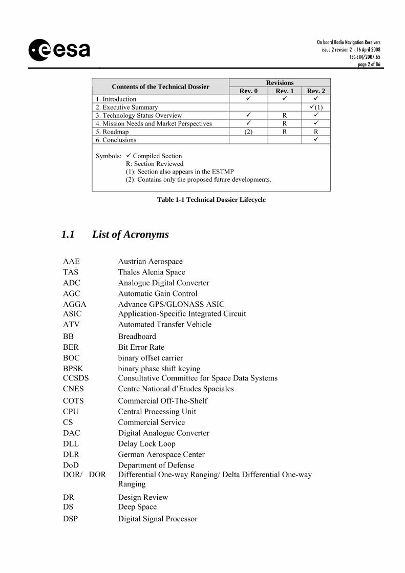
Revisions Contents of the Technical Dossier Rev. 0 Rev. 1 Rev. 2
1. Introduction 2. Executive Summary (1) 3. Technology Status Overview R 4. Mission Needs and Market Perspectives R 5. Roadmap (2) R R 6. Conclusions Symbols: Compiled Section R: Section Reviewed (1): Section also appears in the ESTMP (2): Contains only the proposed future developments.
Table 1-1 Technical Dossier Lifecycle
1.1 List of Acronyms AAE Austrian Aerospace TAS Thales Alenia Space ADC Analogue Digital Converter AGC Automatic Gain Control AGGA Advance GPS/GLONASS ASIC ASIC Application-Specific Integrated Circuit ATV Automated Transfer Vehicle BB Breadboard BER Bit Error Rate BOC binary offset carrier BPSK binary phase shift keying CCSDS Consultative Committee for Space Data Systems CNES Centre National d’Etudes Spaciales COTS Commercial Off-The-Shelf CPU Central Processing Unit CS Commercial Service DAC Digital Analogue Converter DLL Delay Lock Loop DLR German Aerospace Center DoD Department of Defense DOR/�DOR Differential One-way Ranging/ Delta Differential One-way
Ranging DR Design Review DS Deep Space DSP Digital Signal Processor

On board Radio Navigation Receivers
issue 2 revision 2 - 16 April 2008 TEC-ETN/2007.65
page 3 of 86
EADS European Aeronautic Defense and Space Company EBB Elegant Breadboard ECSS European Cooperation for Space Standardisation EDAC Error Detection And Corrections EGNOS European Geostationary Navigation Overlay System EM Engineering Model EO Earth Observation ESA European Space Agency ESBT Experimental S-Band Terminal ETSI European Telecommunication Standards Institute FAR Final Acceptance Review FEC Forward Error Coding FPU floating point unit FF Formation Flying FFT Fast Fourier Transform FLL Frequency Locked Loop FM Flight Model FPGA Field Programmable Gate Array GEO Geostationary Earth Orbit GTO GEO transfer Orbit GIOVE Galileo In-Orbit Validation Element GLONASS Global Navigation Satellite System GMSK Gaussian Minimum Shift Keying GNC Guidance & Navigation Control GNSS Global Navigation Satellite System GPS Global Positioning System GPSOS Global Positioning System Occultation Sensor GRAS Navigation Satellite System Receiver for Atmospheric Sounding GSFC NASA Goddard Space Flight Center GSP General Studies Programme GSTB Galileo System Test Bed GSTP General Support Technology Programme H/W Hardware HEO Highly Eccentric Orbit HPA High Power Amplifier HW Hardware IF Intermediate Frequency I/F Interface IAR Integer Ambiguity Resolution ICD Interface Control Document IEEE Institute of Electrical and Electronics Engineers
On board Radio Navigation Receivers
issue 2 revision 2 - 16 April 2008 TEC-ETN/2007.65
page 4 of 86
IOV In-Orbit Validation INS Inertial Navigation Unit ISRO Indian Space Research Organisation ISS International Space Station ITU International Telecommunications Union JAXA Japan Aerospace Exploration Agency JPO GPS Joint Program Office JPL Jet Propulsion Laboratory KaTE Ka-band Transponder Equipment LEO Low Earth Orbit LNA Low Noise Amplifier MEO Medium Earth Orbit MEMS Micro-Electro-Mechanical Systems MMIC Monolithic Microwave Integrated Circuit MPTS Multi Purpose Tracking System MTLL Mean Time to Lose Lock MSR Mars Sample Return NASA National Aeronautics and Space Administration NCO Numerically Controlled Oscillator NE Near Earth NOAA National Oceanic & Atmospheric Administration OBCU On-Board Computer Unit OEM Original Equipment Manufacturer OP Open Service OQPSK Offset Quadrature Phase Shift Keying PC Personal Computer PDT Payload Data Transmitter POD Precise Orbit Determination PLL Phase Lock Loop PRN Pseudo Random Noise PRS Public Regulated Service PVAT Position, Velocity, Attitude and Time PVT Position, Velocity and Time RAIM Receiver Autonomous Integrity Monitoring R&D Research and Development RF Radio Frequency RFDU Radio Frequency Distribution Unit RTU Remote Terminal Unit Rx Receiver S/C SpaceCraft S/S Sub-System

On board Radio Navigation Receivers
issue 2 revision 2 - 16 April 2008 TEC-ETN/2007.65
page 5 of 86
SAR Synthetic Aperture Radar SBAS Satellite Based Augmentation System SCFG Space Coordination Frequency Group SDR SW Defined Radio SMART Small Missions for Advanced Research in Technology SMOS Soil Moisture and Ocean Salinity Mission SoL Safety of Life S&R Search & Rescue SRRC Square-Root Raised Cosine SS Spread Spectrum SSTL Surrey Satellite Technology Ltd SW Software TC Telecommand TCAR Three Carrier Ambiguity Resolution TCM Trellis-Coded Modulation TDMA Time Division Multiplex Access TDRSS Tracking and Data Relay Satellite System TM Telemetry TRL Technology Readiness Level TRP Technology Research Program TT&C Telemetry, Tracking and Command TTFF Time-To-First-Fix Tx Transmitter UART Universal Asynchronous Receiver/Transmitter UMTS Universal Mobile Telecommunications System VCO Voltage Controlled Oscillator VHDL Very High-level Design Language VLBI Very Long Base line Interferometry VLSI Very Large Scale Integration WAAS Wide Area Augmentation System WIU Waveguide Interface Unit WLAN wireless local area network
On board Radio Navigation Receivers
issue 2 revision 2 - 16 April 2008 TEC-ETN/2007.65
page 6 of 86
2 EXECUTIVE SUMMARY
Introduction On-board radio navigation receivers (GNSS receivers) are used in spacecraft platforms as a navigation sensor to determine spacecraft attitude, relative and/or absolute orbit position, velocity and time. Radio navigation receivers can also be used as scientific instruments for EO/Sci missions to perform precise orbit determination, atmospheric sounding and ocean reflection measurements.
Typically, the GNSS receivers, from technology point of view, are classified by the number of frequencies, single and multiple-frequency receivers, according to the type of mission, navigation and scientific oriented applications respectively. However, it is also possible to divide spaceborne GNSS applications into high-end missions on the one side and medium to low-budget missions on the other.
Some core technologies and techniques can be considered common between the several receiver types, such as basic signal processing techniques, HW building blocks and basic navigation algorithms. Some others are application specific, and must be defined and developed for every mission.
The harmonisation has been conducted previously in 2002. Since then applications, requirements and the industrial landscape has significantly changed (new GNSS systems and modernisation plans). At the same time the implementation of the ESA supported activities has suffered from budget limitations. The revisit of this subject has allow to update the overview of the various kinds of receivers present on the market, their applications and to significantly update the roadmap prepared in 2002 to realign with the present status of technology and the expected future applications. Harmonised Roadmap During the 2007 harmonization process, several important points have been highlighted. Europe is currently the world leader for GNSS space receivers. The competitiveness of the European industry in the field has been achieved thanks to the support of technology development through ESA and other European agencies. Furthermore, European technology has benefited from the synergy between commercial and institutional markets. Purchase from U.S. of state-of-the-art GPS receivers is often limited by export restrictions. It is therefore essential to ensure the availability of several European sources. The Roadmap agreed with THAG highlights the following points:
• The proposed approach covers the several types of GNSS space receivers: low cost receivers based on COTS, high reliability receivers (SF and MF) and scientific instruments.
• Two or three different companies are addressing each of these markets and it is considered enough. ESA has focused on the last two markets, in collaboration with national delegation, leaving the low cost receivers for industry or national agencies.

On board Radio Navigation Receivers
issue 2 revision 2 - 16 April 2008 TEC-ETN/2007.65
page 7 of 86
• The strategy claims for development of innovative GNSS receivers and scientific
instruments covering the new GNSS signals, consolidation of the already initiated core technologies (RF and Baseband ASICs), and development of navigations prototypes for supporting space exploration.
• SW based receivers are covered only at feasibility level.
On board Radio Navigation Receivers
issue 2 revision 2 - 16 April 2008 TEC-ETN/2007.65
page 8 of 86
3 TECHNOLOGY STATUS OVERVIEW
3.1 Technology Overview On-board radio navigation receivers (GNSS receivers) are used in spacecraft platforms to determine spacecraft attitude, relative and absolute orbit position, velocity, and time. Radio Navigation receivers can also be used as scientific instruments to perform gravity, atmospheric sounding, ocean reflection, and ionospheric sounding measurements. The vast majority of Low-Earth Orbit (LEO) satellites planned, built and launched over the last years rely primarily on GNSS measurements for timing and navigation purposes. A key advantage of employing GNSS sensors in space projects is the great potential in cost savings in both satellite equipment and operational mission costs. Various functionalities traditionally provided by separate devices, such as absolute and relative positioning, attitude determination and precise timing, can now be combined into a single, light-weight, power and cost efficient unit. Furthermore, the availability of this information onboard a spacecraft paved the way for an increased level of onboard autonomy in the operation of a satellite. This, in turn, results in a considerable reduction of the costs related to ground operations of a spacecraft.
While the hardware development paths of on-board radio navigation receivers for spacecraft platforms and for scientific applications are somewhat similar, the requirements for the two kinds of receivers may differ significantly. For example, reliability, radiation hardness, data requirements, and receiver operations for a receiver designed for a platform are very different from those for a science instrument. This is primarily because a receiver used on a satellite platform is needed for maintaining spacecraft health and is geared towards reducing space mission costs through reduced sensor complements and enhanced vehicle autonomy. On the other hand, objectives of most scientific applications demand extensive real-time and post processing, performed both onboard and as part of the ground operations. A scientific instrument using navigation signals is generally quite different, hardware-wise too, from a navigation receiver (platform receiver).
Today, several important changes in the satellite navigation infrastructure are taking place that require firm accompanying efforts in the area of technology development: • The SBAS systems, in particular EGNOS and WAAS, are already available and make
possible the development of the potential new space applications related with integrity. • GPS and GLONASS systems are under a modernisation process, committed by the US
and Russian Government, with the inclusion of two new civil frequencies with new signal structures that bring significant enhancements to current applications. This fact opens specially a field for research and development of new technology for space applications.

On board Radio Navigation Receivers
issue 2 revision 2 - 16 April 2008 TEC-ETN/2007.65
page 9 of 86
• The European Commission and ESA are developing Galileo, which represents a
considerable challenge with regard to new technical developments and the development of possible new applications.
• The new GNSS Chinese system, Compass, as it will be important for both platform
receivers and ‘scientific’ applications. Annex B provides further details about the current and new GNSS signals and the modernisation plans of the various GNSS systems. At the same time, the ongoing advances of micro and nanotechnologies combined with new satellite navigation and formation-flying concepts have made it possible to conceive new space systems that were unthinkable before. The successful implementation of these systems, by developing the suitable GNSS space technologies represents a challenge that could open the door to a new era in space exploration and space applications. Typically, the GNSS receivers are classified by the number of frequencies, single and multiple-frequency receivers, according to the type of mission, navigation (platforms) and scientific oriented applications respectively. However, it is also possible to divide spaceborne GNSS applications into high-end missions on the one side and medium to low-budget missions on the other. Typically the first group are international large-scale projects generally equipped with reasonable engineering as well as financial resources. The second category of projects consists typically of small-scale scientific satellites or technology demonstration missions with less demanding requirements on receiver qualification status. Furthermore a growing number of universities have started to build or already launched their own satellites for educational purposes. The key difference between both categories of spaceflight projects, apart from the satellite size and the overall budget, are the ultimate demands for reliability and robustness of the employed components in the high-end segment. The requirements and demands with regard to accuracy, performance and flexibility of the employed navigation equipment, on the other hand, are commonly identical for both classes of missions.
3.2 Areas Covered by this Technology Dossier This technical dossier provides an overview of the various kinds of GNSS space receivers and of their applications with the aim of providing a picture of the present status of technology and an overview of the expected future trends. The Harmonisation addresses all types of On-Board Navigation Receivers and their core technologies, including: • Single Frequency (SF) • Multiple Frequency (MF) • Low Cost (LC), based on COTS parts • Core technologies: Radio Frequency (RF) and Base-Band (BB) processing The relevant technology domain of the ESA Technology Tree is TD 6-B.

On board Radio Navigation Receivers
issue 2 revision 2 - 16 April 2008 TEC-ETN/2007.65
page 10 of 86
3.3 Rationale for Harmonisation of the Technology GNSS receivers are used in many different space scenarios, covering a wide range of complex applications. Some core technologies and techniques can be considered common between the several receiver types, such as basic signal processing techniques, HW building blocks and basic navigation algorithms. Some others are application specific, and must be defined and developed for every mission. Harmonisation is justified by the level of complexity of these involved technologies and techniques together with the limited potential market for applications. The Harmonisation on Radio Navigation Receivers has been conducted previously in 2002. Since then applications, requirements and the industrial landscape has significantly changed. At the same time the implementation of the ESA supported activities has suffered from budget limitations. The revisit of this subject is intended to update the overview of the various kinds of receivers present on the market, their applications and to update the roadmap prepared in 2002 to realign with the present status of technology and the expected future applications.
3.4 Technology State of the Art
3.4.1 PROTOTYPES, EXPERIMENTS AND FIRST RECEIVERS The era of spaceborne GPS positioning began with the launch of the Landsat 4 spacecraft in 1982, several years before GPS entered the full operational status. The Landsat-4 spacecraft carried the first (civilian) spaceborne GPS receiver onboard and successfully demonstrated the feasibility and usefulness of utilizing Global Navigation Satellite System (GNSS) signals for navigation purposes in space projects. About one decade thereafter, in 1992, the Topex/Poseidon mission marked a further important milestone in the evolution of space-borne radio navigation. The precise orbit determination (POD) experiment conducted in the frame of this mission has nicely illustrated the accuracy potential of using GPS data for the reconstruction of a LEO orbit. In 1995 was the first space operation of GPS occultation measurement system (US – NASA JPL). In 2005 took place the first space operation of a Japanese GPS receiver (JAXA). Finally, the first space operation of a GEO GPS receiver was on GIOVE-A (UK – SSTL) in 2006.

On board Radio Navigation Receivers
issue 2 revision 2 - 16 April 2008 TEC-ETN/2007.65
page 11 of 86
Activities in ESA in the field of Navigation started in 1985, geared towards the investigation of the possible applications of GPS to spacecraft. Since then the following subjects have been covered: • In-orbit navigation and orbit determination. • Spacecraft attitude determination • Differential navigation for in-orbit rendezvous operations • Formation Flying • Atmospheric sounding • Atmospheric re-entry and Guidance for landing (Hermes)
During that time the first European GPS receiver for space was developed by Alcatel SEL (D) for Hermes and successfully tested in the European Navigation laboratory (ENL) at ESTEC. The first use of GPS on a microsatellite in space was in 1993 on the joint Portuguese – British PoSat-1 microsatellite. A Trimble TANS receiver was successfully flown and operated to generate on-board mean orbital elements. The GPS Tensor space receiver from Laben (I) was thoroughly tested, by the end of the 90’s, at the navigation laboratory in ESTEC and at Laben, to demonstrate its performance in the rendezvous scenario between the ISS and ATV. A closed loop simulation set-up was tested successfully in ESA in 1996 in order to introduce the ATV guidance and control effects in the simulation loop. This set-up has been adopted by industry, MMS (F), and by the ATV project, in order to further study the rendezvous scenarios. Some efforts were made in ESA by the end of the 90’s in order to consolidate the development of in-orbit navigation and attitude determination based on satellite navigation. A number of activities were initiated in ESA and as a result of these efforts, the following activities were carried out: • Two attitude determination prototypes were developed with several companies
(Sextant (F)/MMS (F)/GMV (E), Laben (I)) in order to study the different receiver architectures and determine the performance experimentally on the ground.
• An experimental GPS attitude receiver (ready in 1999) was developed and launched on UoSAT-12 by SSTL (UK). This receiver allows flexible testing of attitude determination algorithms in flight and is well suited for small satellites (low mass and volume). Autonomous orbit control (drag removal) using GPS was demonstrated for the first time on UoSAT-12 for 1 year.
• A GPS receiver breadboard based on the AGGA (Advanced GPS and Glonass ASIC) featuring position, attitude and time determination was developed and tested by Astrium (D)/(F). The AGGA Asic is a high-complexity device implementing the high-speed signal processing for GPS and Glonass receivers targeting a number of space related applications such as spacecraft control, precise orbit determination and atmospheric sounding.

On board Radio Navigation Receivers
issue 2 revision 2 - 16 April 2008 TEC-ETN/2007.65
page 12 of 86
Since then, ESA has covered both, scientific instruments and platform receivers. Concerning instruments, ESA activities have lead to the GRAS (SE/AAE) and SSTI (Label) instruments. GRAS being the first GPS/GLONASS dual-frequency receiver for operational use in orbit since 2006. ESA, in partnership with CNES and Alcatel Space Industries (F), developed the first European multipurpose space qualified receiver (TOPSTAR 3000) based on previous developments for airborne receivers. Its most outstanding characteristics were its low acquisition and tracking threshold and its ability to navigate in all kind of orbits (LEO/GTO/GEO) thanks to its internal orbit propagator able to operate in code-only mode. This receiver, together with the SGR family (SSTL (UK)), the MosaicGNSS (Astrium (D)) and the receivers from Laben (I) have been the precursors of the satellite navigation based on GNSS. It is also important to remark a number of ESA patents, widely requested and licensed to e.g. Saab Space, Austrian Aerospace, TAS-F, TAS-I, Septentrio and Astrium. These represent valuable European assets, especially to avoid proliferation of (sub-optimal) solutions. The main following milestones are expected in the coming years: • 2008 First space operation of T3000G2 multipurpose GPS receiver (France - Thales
Alenia Space), compatible with the new GPS L2C signal. • 2009 New space receiver development with Galileo compatibility at ASIC level
(Austrian Aerospace) • 2011 GPSOS (scientific measurements) operation on NPOESS-2. Cancel. • 2013 Full modernised GPS Space Receiver operation (US – General Dynamics &
ITT).
3.4.2 TECHNOLOGY STATE-OF-THE ART European industry is able to supply several off the shelf products to perform GNSS based orbit (and attitude) determination function on board satellites. Several companies provide single, multiple frequency and low cost GNSS receivers:
• Single frequency space receivers: TAS-F, TAS-I, EADS Astrium (D) • Multiple frequency receivers: AAE/Saab (A,S), TAS-F, TAS-I, EADS Astrium (D) • Low cost space receivers: based on COTS parts, SSTL(UK) and DLR (D).
This chapter also gives an overview of the core technologies used by these receivers.
3.4.2.1 Single Frequency Space Receivers
• TOPSTAR 100 (TAS-F). This receiver is derived from a military receiver of Sextant Avionique, modified to remove its Y code tracking capability. It was specifically developed for the ESA Atmospheric Re-entry Demonstrator (ARD) mission, launched

On board Radio Navigation Receivers
issue 2 revision 2 - 16 April 2008 TEC-ETN/2007.65
page 13 of 86
by ARIANE 503 in 1998. It used 10 GPS C/A code channels, provided with acquisition and tracking functions assisted by inertial measurements delivered by the ARD IMU (Inertial Measurement Unit). This feature allowed this receiver to acquire and track some GPS satellites provided with a C/No ratio of 20 dBHz in the middle of the radio black-out occurring during the re-entry phase. This allowed also a very quick reacquisition of the GPS satellites after the black-out phase. More generally, this capability named “Code Only” allowed a robust tracking of 9 GPS satellites during all the mission (excepted during the black-out).
• TOPSTAR 3000 G1 (TAS-F). This is a product ready to be used in almost any kind of Earth orbiting mission. It is a fully qualified modular space borne receiver adaptable to several kind of missions (LEO, GTO, GEO) and with capability for both positioning and attitude determination function. It has very low acquisition thresholds and enhanced navigation capabilities due to its orbital propagator. It is the result of collaboration between ESA, CNES and Thales Alenia Space France. Main features are: C/A code L1-band GPS or GLONASS receiver, 12 to 24 parallel channels, interface with 1 to 4 antennas, dynamic compatibility with all types of earth orbits, accurate orbital navigator implemented, navigation data (Position Velocity Time), high rate carrier phase measurement for attitude control, user interface: RS422 (1553B optional), 1,5 kg mass and 6-12 watts consumption. This receiver can be provided with an Autonomous Orbit Control software, providing directly to the On Board Computer the manoeuvre descriptions. This receiver is also used operationally for orbit determination and timing on board several non European earth observation missions, and will be used on board the Alpha Magnetic Spectrometer experiment of the ISS. This receiver is also provided with the “Autonomous Code Only” technique, allowing acquisition and tracking of GPS C/A codes having a C/No ration so low as 20 dBHz, without any external aiding.
• GPS Tensor (TAS-I). Space-qualified, GPS attitude and orbit determination receiver. It has the unique feature to offer 13 output states of navigation and attitude information, for guidance and control of space vehicles. GPS Tensor™ delivers position, velocity, time and filtered orbit determination using a continuous-tracking, 9-channels L1 C/A code receiver. When configured with four antennas, GPS Tensor™ provides platform roll, pitch, and yaw angles and rates. GPS Tensor™ has been selected as navigation receiver on board several satellites already launched or under development, including Globalstar and several US missions. GPS Tensor™ will be also used on the ESA Automated Transfer Vehicle (ATV) for the Rendezvous and Docking operations to International Space Station. This receiver is also used in all current TAS-F Proteus platforms (Jason-1, Corot, Calypso, etc.) for the real-time orbit determination using a dual antenna for increased FOV and non-zenith pointing attitudes. Other 3 receiver are actually foreseen for this mini-series: Corot (2006), SMOS (2007) and Jason2 (2008).
• GPS Pointer™ (TAS-I). It is a low cost orbit determination receiver ideal for any satellite in LEO orbit. GPS Pointer™ provides position, velocity and time determination by means of 12 parallel C/A code channels at L1 band. Filtered orbit determination is also available. GPS Pointer™ can be operated with two antennas for improved sky coverage in any platform attitude. GPS Pointer™ development was discontinued in favour of other dual-mode GPS & Galileo products. GPS-only receivers

On board Radio Navigation Receivers
issue 2 revision 2 - 16 April 2008 TEC-ETN/2007.65
page 14 of 86
(“GPS-A”) derived/simplified from the Globalstar (former “Tensor”) are still used for positioning and autonomous navigation without attitude determination.
• MosaicGNSS Receiver (Astrium, D) is a small design with only radiation hardened European parts for space applications from LEO to GEO. It can be used as a stand-alone unit or as an integral part of the OBCU. The MosaicGNSS Receiver is available with two signal processing cores. One uses software correlation, providing 8 L1 GPS channels with a low acquisition/tracking threshold. Its very fast signal acquisition results in an unique cold start capability. Its software flexibility allowed the extension to EGNOS and a first prototype Galileo signal receiver. The other core is AGGA-2a based with 12 channels and has additionally been used for GLONASS reception and attitude determination. Both cores are complemented by a navigation module with a specialized filter to manage Earth orbits from LEO to GEO. The receiver has been extended to perform Precise Relative Navigation for formation flying, rendezvous manoeuvres and co-location in GEO. The AODS extension incorporates Star Sensors and Gyros for delivering an unified satellite state vector of position and attitude. Its performance has been verified in a real-time closed loop test bed.
3.4.2.2 Multiple Frequency Space Receivers • GRAS (SES/AAE) : SAAB Ericson Space (SES) and Austrian Aerospace (AAE)
developed a GPS/GLONASS instrument for atmospheric sounding, so-called GNSS Occultation Sensor. The AAE contribution consists of the so-called Channel Processing based on the TSC 21020F DSP processor and the Advanced GPS and GLONASS ASIC (AGGA-2). These developments have been done under the ESA EOPP and METOP/GRAS programmes. A similar instrument (the GPSOS) has been exported to the U.S. Earth Observation organisation NOAA.
• LAGRANGE™ (TAS-I): GNSS Receiver for Advanced Navigation, Geodesy and
Experiments (LAGRANGE™) is a multi-standard receiver operating with both GPS and GLONASS constellations. The system provides precise navigation output as well as accurate measurements of GPS and GLONASS observables, including differential L1/L2 measurements. LAGRANGE™ operates with 16 dual frequency GNSS parallel channels for navigation and Precise Orbit Determination (POD) by means of ground processing. LAGRANGE™ can be also configured with additional hardware and software in order to perform radio occultation measurements for atmospheric profiling missions. The first prototype of the LAGRANGE™ was on board the Argentinean spacecraft SAC-C for a Precise Orbit Determination (POD) experiment, and will fly in the GOCE spacecraft as POD instrument. Lagrange has also been used on Radarsat2 and COSMO-Skymed (5 satellites). In May 2005 the receiver flown on the Soyuz / ISS in the frame of the ENEIDE mission successfully testing the first combined GPS-GEO (EGNOS-WAAS) tracking experiment from space.
• LAGRANGE ROSA™ (TAS-I): Lagrange ROSA (Radio Occultation Receiver for
Sounding the Atmosphere), developed under ASI contract (Agenzia Spaziale Italiana),

On board Radio Navigation Receivers
issue 2 revision 2 - 16 April 2008 TEC-ETN/2007.65
page 15 of 86
is an instrument to sound the earth atmosphere with the Radio Occultation Technique. Besides providing real-time navigation data with good accuracy, ROSA is able to measure pseudo ranges and carrier phase to be later processed on ground to calculate the main physical parameters to perform meteorology and climatology science. ROSA processes the received GNSS signals both in L1 and L2 frequency bands, allowing compensation of ionosphere delays. Pseudorange, carrier phase and SNR (Amplitude and Noise estimates) data are generated in closed loop tracking mode at 1-10-50 Hz (depending on sounding altitude). ROSA is provided with a MIL-STD-1553 communication interface. The instrument is equipped with one hemispherical coverage antenna with boresight direction equal to the Zenith direction and two (or one) Radio Occultation Antenna oriented with the maximum gain at the atmosphere layer from 0 to 100 km. The first flight will be on ISRO mission Oceansat2 scheduled in 2008. A second unit on and Argentinean Satellite in 2008 too.
• Innovative GPS Receiver (IGPS) based on AGGA-2 (AAE-A and NemeriX-CH): it
is based on the AGGA-2 and NemeriX FE ASICs. The RF board is equipped with two G3RF mixed signal ASICs (NemeriX) and custom-designed surface-acoustic wave (SAW) filters. The baseband signals are A/D-converted by two G3AD ASICs, (NemeriX), on the digital processing board and then read in by two AGGA-2 ASICs. The two AGGA-2 hosted by receiver allow for dual-frequency measurements in 8 channels. The LEON processor is the controller of the whole board. It communicates with the AGGA-2 ASICs and closes the GPS signal-processing loop in software. The LEON is also responsible for handling the TM/TC interfaces. The dimensions are (W, L, H ) 240 x 300 x 98 mm3, resulting in a mass of approximately 2.5 kg without antenna and harness. Power consumption is around 10 W for a fully loaded receiver under steady-state conditions. The EM development has been done under the ESA ARTES-5 programme.
• GPS-POD receiver (AAE-A, SAAB-S): The IGPS receiver developed by AAE can be
used for navigation and Precise Orbit Determination (POD), and can also be also configured with additional hardware and software in order to perform radio occultation measurements for atmospheric profiling missions. One EM and two FMs of a GPS-POD receiver is being done under the ESA SWARM programme, with AAE (A) and SES (S).
• TOPSTAR 3000 G2 (TAS-F): T3000 G2 has been developed by THALES ALENIA
SPACE (including Thales Avionics, Syderal and NORSPACE), under ESA and CNES contract. This new generation covers short and medium spacecraft navigation needs for both LEO and GEO missions. With regards to the preceding generation of single frequency receivers, the new product offers around 30% mass saving and additional functionalities: GPS L2 civilian signal (L2CS) processing and pseudolite signal (Lp) processing. The receiver can work in single or dual frequency, and in more complex configurations, as those required by multi-antenna dual-frequency instruments or attitude determination. For LEO missions the introduction of GPS L2 civil-signal tracking allows also new applications (radio occultation, on ground precise orbit determination). Tracking the GPS L2 Civil Signal (L2CS) has required a significant upgrade of the signal processing chip of the T3000 receiver, because of the new CM
On board Radio Navigation Receivers
issue 2 revision 2 - 16 April 2008 TEC-ETN/2007.65
page 16 of 86
(Civil Moderate) and CL (Civil Long) codes. This tracking capability has already been demonstrated on ground with true signal in space. For GEO missions, significant improvement of performances is obtained by the introduction of pseudolite-tracking capability. The new receiver is able to simultaneously track GPS signals at 1575 MHz (L1) and pseudolite signals at 1340 MHz (Lp). The new receiver first space flight is expected for beginning 2008 for an in orbit technology demonstration in the frame of the ESA PROBA2 mission. TAS-F/I is presently developing a new single frequency version of T3000 G2 for the GLOBALSTAR 2 constellation (96 flight models) and other missions.
• LION Navigator (EADS Astrium D): planned development of a next generation
GPS/Galileo receiver. It is based on the AGGA device evolution (AGGA-3/AGGA-4), and using existing building blocks and new elements available and/or supported by the space agencies.
3.4.2.3 Low Cost Space Receivers Based on COTS Parts • Space GPS Receiver (SGR-xx) series (Surrey Satellite Technology Ltd, UK). SSTL
has built a Space GPS Receiver series based on the commercial Mitel GP2000 chipset, the ARM60 processor and a CAN bus. After a radiation test programme undertaken together with ESA, an overall figure of 10-15 Krad can be assumed. A bank of SRAM protects against Single Event Upsets through the use of Error Detection And Corrections (EDAC) circuitry. A fast acting current sensing switch is included to protect against Single Event Latch-ups. The SGR-20 (for attitude determination) and SGR-10 (PVT) weight 1 kg and have a power consumption of 5 to 7 W. The SGR-05U, for nanosatellites, has a mass of 20 grams and a power consumption 1 W, but has no EDAC protection, SEL switch and advanced communications functions; although risks can be significantly reduced by its intermittent mode of operation. An enhanced version, the SGR-05P has EDAC protection and FRAM initialisation but retains the miniature size. A packaged version of this, the SGR-07 is available for ease of integration on spacecraft. SGR receivers have flown successfully in multiple small satellite missions, like SSTL’s DMC satellites, the ESA mission PROBA, NASA, USAF and others around the world. They have also been selected for the ISS. SGR receivers have established world premieres in the area of autonomous navigation, orbit control, attitude determination and reflectometry. SGR-GEO is a 24-channel GPS receiver optimised for use in medium Earth and geostationary orbits (MEO/GEO). The SGR-GEO is based upon the Zarlink GP4020 and GP2015 chipsets. The receiver uses a combination of a directional patch antenna, and weak signal tracking algorithms in order to increase the number of visible SVs in MEO/GEO. In addition, the flight software incorporates an orbit estimator to allow navigation output even when the GPS navigation solution is under-determined, creating the potential for continuous autonomous navigation and station keeping for geostationary satellites.
• GPS Orion (DLR, D): The GPS Orion is a prototype receiver design for the Mitel
(now Zarlink) GPS2000 chipset. It features 12 channels L1 C/A code tracking and is
On board Radio Navigation Receivers
issue 2 revision 2 - 16 April 2008 TEC-ETN/2007.65
page 17 of 86
particularly suited for applications requiring low weight (50g) and power consumption (2W) without pronounced radiation hardness requirements. The software has been adapted for space applications including both orbiting spacecraft and high dynamics ballistic vehicles (sounding rockets, re-entry capsules). Tailored s/w versions are available to optimally support each mission class and to handle specific applications like onboard impact point prediction for range safety purposes or kinematic relative navigation of formation flying spacecraft. Receivers can be made available by DLR for research projects or commercial users
• The Phoenix miniature GPS sensor (DLR, D): is the second generation spaceborne
GPS receiver for LEO satellite and high-dynamic applications developed at DLR/GSOC. It represents a low-cost single-board GPS navigation sensor for tracking of L1 C/A code and carrier signals on 12 parallel channels. The Phoenix receiver combines COTS hardware components with GPS signal processing software specifically designed for navigation of LEO satellites, rockets and re-entry vehicles. The Phoenix employs a commercially available hardware platform, the MG5001 receiver board, manufactured by Sigtec Navigation Pty., Australia. The MG5001 is built around the GP4020 chip of Zarlink, which combines a 12 channel correlator for L1 C/A code and carrier tracking. Phoenix receivers have been regularly used in European and international sounding rocket projects, employed as prime navigation sensor for flight safety purposes as well as post-facto performance analysis. The Asolant/Rubin-5 experiment marked the maiden flight of the receiver in a satellite mission. Over the next years Phoenix-S receivers will, furthermore, be flown on a number of upcoming satellites projects such as ESA’s Proba-II mission, the Singaporean X-Sat satellite or the Swedish Prisma formation flying mission.
• Septentrio(B)/Novatel(CN): These are COTS terrestrial receivers, single and dual
frequency, prepared for space. DLR/GSOC have performed qualification tests for the commercial Novatel OEM-4 and Septentrio PolaRx2 receivers, that will be flown in missions such as Cassiope or the German On Orbit Verification (OOV) respectively. Further qualification tests and development are devised for the upcoming GITES/GORS mission promoted by the GeoForschungZentrum (GFZ).
3.4.2.4 Core Technologies
3.4.2.4.1 RF FE
RF FE technologies and manufacturers are: • In-house RF ASICs. Some companies have developed their own RF chipset for their
own needs. This is the case for instance of TAS-F which has developed with the support of CNES the CRF1 chip which is implemented in the TOPSTAR 3000 receivers and its derivates. This chip allows, depending on the number and on the configuration of the antennas, the reception of L1 or Lp or L1/L1 or L1/L2 or L1/Lp.

On board Radio Navigation Receivers
issue 2 revision 2 - 16 April 2008 TEC-ETN/2007.65
page 18 of 86
• NemeriX RF ASICs: This FE chip-set has been developed by Nemerix (CH) under
ESA contract with AAE (A) as prime. The chip-set comprises 2 ASICs, an RF front-end referred to as G3RF (NJ1007R) and an AD converter ASIC (NJ1017CR), named G3AD. The G3RF ASIC is the key component of the RF front-end. The chip is manufactured in a 0.35 μm SiGe process. The G3RF ASIC provides a low-noise amplifier (LNA) and a heterodyne down converter from L-band to an intermediate frequency (IF), followed by quadrature down conversion to base band and active 15MHz low-pass filtering. The G3RF is in fact able to receive all GPS, Galileo and GLONASS signals up to a bandwidth of 24 MHz. The G3AD mixed signal ASIC contains two 50 MHz A/D Converters with 3-bit resolution, a PLL for sampling clock generation and a digital-to-analogue (D/A) converter providing the AGC-voltage. Both ASICs have been designed by NemeriX as radiation tolerance by design. These techniques include the use of continuous guard rings, increased distances and overlaps between diffusions, error correcting registers, and other techniques developed by NemeriX to prevent latch-ups, parametric shifts or single event effects. The respective specifications are 100 krad(Si) for total dose and 70 MeV/mg/cm2 for heavy ions.
• ChipIdea RF ASIC: within an ESA contract, ChipIdea (P) is currently developing a
monolithic Galileo/GPS front-end ASIC for GNSS receivers. The chip allows multiple band reception (E1 / L1 / L2 / E5a / E5b / E6) with simultaneous reception of: L1/L2 or L1/E6 or L1/E5a or L1/E5b or L1/E5a+E5b. The chip includes on-chip filtering (with only external LNA and RF Filters), zero IF with DC cancellation, fully integrated PLL and automatic gain control. The ASICs operates with 1.8 V single supply and a current consumption of 25 mA. (See also micro-electronics dossier).
• IMEC RF ASIC: under ESA contract, IMEC (B) is currently developing a high-
performance low-power front-end for multi-band satellite navigation systems in space. The signal reception is performed on an upper band for GPS L1 and GLONASS L1 and on a lower band for GPS L2, GPS L5, and GLONASS L2. 232 MHz is the sampling frequency for the ADC. A further (external) down-sampling and demodulation can be added to provide 2 bit IQ signals, which can directly be feed into an AGGA-2. (See also micro-electronics dossier).
Table 3-1 provides an overview of RF front-end building blocks, which do exist today or in near future. In-house RF ASICS developed by some companies for their own needs are not included.

On board Radio Navigation Receivers
issue 2 revision 2 - 16 April 2008 TEC-ETN/2007.65
page 19 of 86
Table 3-1: overview of the European RF front-end building blocks
RF ASIC Company
Ctry Fund Freq. Bands Output Status
NemeriX
CH
ESA
• GPS: L1, L2, L5 • GLONASS: L1, L2 • Galileo: L1, E5a, E5b, E6
3 bit complex at 50 Mhz
Under Qualification
ChipIdea
P
ESA
• GPS: L1, L2 • GLONASS: L1, L2 • Galileo: L1, E5a, E5b, E6
Zero IF for an external ADC
On-going (see micro-electronics
dossier)
IMEC
B
ESA • GPS: L1, L2, L5 • GLONASS: L1, L2 • Galileo: L1, E5a, E5b
1 bit real at 232 MHz
Cancel (see micro-electronics
dossier)
3.4.2.4.2 Base-Band Processing
Base-band processing technologies and manufacturers are: • In-house Baseband ASICs: based on in-house knowledge and skill, some companies
have developed their own baseband chips for their own needs:
o PEGASE chips (TAS-F): TAS-F has developed with the support of CNES two versions of radiation-tolerant signal processing PEGASE chips for GPS civil signals. These Asics are mounted on-board the single or dual frequency TOPSTAR 3000 receivers. The first generation of this Asic was developed in the frame of an ESA contract in 1995 and features 15 multi-standard channels (GPS, GLONASS) and interfaces with 2 RF/IF down-converters. The second generation, PEGASE2 developed in 2006, is composed of 12 parallel hardware channels with various correlator spacing capabilities (down to 1/16 chip) for multipath mitigation.
o GALVANI correlator (TAS-I): LABEN has developed a GPS-Galileo
baseband correlator which can be conveniently radiation-hardened by design (or ported into rad-hard technology) and become a key building block of future receivers.
• AGGA-2 ASIC: The second-generation of the Advanced GPS/GLONASS ASIC is a
general building block developed by ESA. Implements the channel processing of GPS and GLONASS. The AGGA-2 has 12 single-frequency channels, each capable of tracking a GPS or GLONASS signal with C/A-code, P-code or GPS Y-code on any carrier frequency. Two single- frequency channels can be configured for attitude determination according to the Hybrid Parallel-Multiplex Architecture. Three single-frequency channels can be configured into one dual- frequency channel capable of tracking a GPS or GLONASS C/A-code signal on one carrier frequency (e.g. L1) and

On board Radio Navigation Receivers
issue 2 revision 2 - 16 April 2008 TEC-ETN/2007.65
page 20 of 86
a GPS or GLONASS P-code or Y-code on two carrier frequencies (e.g. L1 and L2). Available since 2000 to the European industry. Includes two ESA international patents. It is used by GRAS, Lagrange and Mosaic. ATMEL part T7905. AGGA-2 product is also mentioned in the microelectronic dossier.
• AGGA-3/4 ASIC: The third generation of the Advanced GPS/GALILEO ASIC
(AGGA-3/4), to be available for 2008, is being developed by ESA under contract with Astrium (G) and Austrian Aerospace (A) as subcontractor, is a radiation-tolerant, low power consumption new generation GNSS baseband ASIC. The AGGA-3/4 includes a GNSS baseband processor, the LEON-FT fault-tolerant microprocessor with its powerful IEEE-754 compliant FPU (GRFPU), an FFT module, UART’s, 4 SpaceWire interfaces and 1 special purpose SW interface. The GNSS baseband processor will be capable of processing the current and future GPS signals L1 C/A, L2C, L5, P(Y) and the open access Galileo signals E5a and E5b. It includes digital down-conversion, beam-forming, enhanced power level detection, code and carrier loop aiding support, and optimised raw sampling for open-loop signal tracking. 36 configurable single-frequency GNSS channels are available. Each channel includes 5 complex code correlators, a dual integration stage for data, decryption or secondary code stripping, a secondary code sequencer, and a carrier and code aiding unit. The AGGA-3/4 includes a 128 point integer FFT module for e.g. fast signal acquisition support. AGGA-3/4 activities are also mentioned in the microelectronic dossier.
Table 3-2 provides an overview of Base-Band digital HW building blocks, which do exists today or in near future. In-house Base-Band ASICs developed by some companies for their own needs are included for information.
Table 3-2: overview of the European Base-Band Digital HW building blocks
BB ASIC
Cmpy Fund Signals Data IFs Status
PEGASE-2
TAS-F
CNES
• GPS L1 C/A, L2C, L5 • Lp
--
Available
(IPR) GALVANI TAS-I GSA • GPS/Galileo FPGA correlator Available for ground
(IPR) ESA is not considering to port GALVANI to a
flight model
AGGA-2
ESA
ESA • GPS & GLONASS • L1, L2 C/A-code, P-code,
GPS P(Y)-code
--
Available
(see micro-electronics dossier)
AGGA-3 AGGA-4
Astrium GmbH
(D)
ESA
• GPS L1 C/A, L2C, L5, P(Y) • Galileo: Open Access signals
in E5a and E5b
4xSpaceWire
2xUART
On-going
(see micro-electronics dossier)
On board Radio Navigation Receivers
issue 2 revision 2 - 16 April 2008 TEC-ETN/2007.65
page 21 of 86
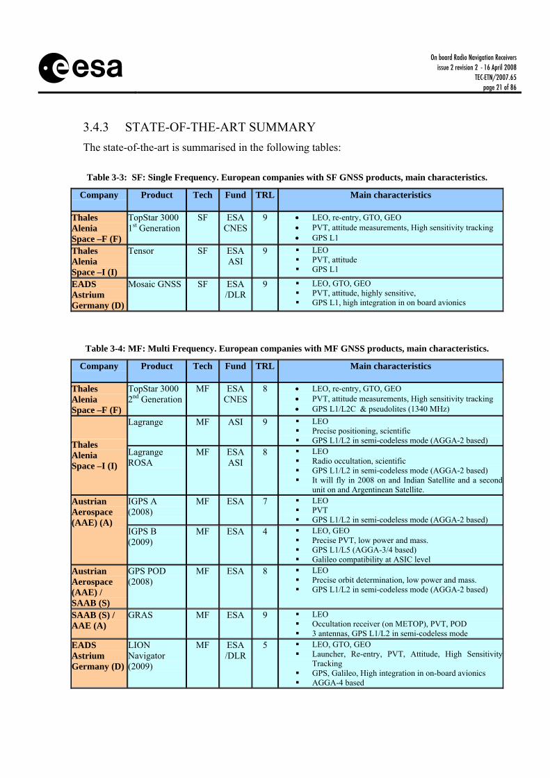
3.4.3 STATE-OF-THE-ART SUMMARY The state-of-the-art is summarised in the following tables: Table 3-3: SF: Single Frequency. European companies with SF GNSS products, main characteristics.
Company
Product Tech Fund TRL Main characteristics
Thales Alenia Space –F (F)
TopStar 3000 1st Generation
SF ESA CNES
9 • LEO, re-entry, GTO, GEO • PVT, attitude measurements, High sensitivity tracking • GPS L1
Thales Alenia Space –I (I)
Tensor
SF ESA ASI
9 LEO PVT, attitude GPS L1
EADS Astrium Germany (D)
Mosaic GNSS SF ESA /DLR
9 LEO, GTO, GEO PVT, attitude, highly sensitive, GPS L1, high integration in on board avionics
Table 3-4: MF: Multi Frequency. European companies with MF GNSS products, main characteristics.
Company
Product Tech Fund TRL Main characteristics
Thales Alenia Space –F (F)
TopStar 3000 2nd Generation
MF ESA CNES
8 • LEO, re-entry, GTO, GEO • PVT, attitude measurements, High sensitivity tracking • GPS L1/L2C & pseudolites (1340 MHz)
Lagrange MF ASI 9 LEO Precise positioning, scientific GPS L1/L2 in semi-codeless mode (AGGA-2 based) Thales
Alenia Space –I (I)
Lagrange ROSA
MF ESA ASI
8 LEO Radio occultation, scientific GPS L1/L2 in semi-codeless mode (AGGA-2 based) It will fly in 2008 on and Indian Satellite and a second
unit on and Argentinean Satellite. IGPS A (2008)
MF ESA 7 LEO PVT GPS L1/L2 in semi-codeless mode (AGGA-2 based)
Austrian Aerospace (AAE) (A)
IGPS B (2009)
MF ESA 4 LEO, GEO Precise PVT, low power and mass. GPS L1/L5 (AGGA-3/4 based) Galileo compatibility at ASIC level
Austrian Aerospace (AAE) / SAAB (S)
GPS POD (2008)
MF ESA 8 LEO Precise orbit determination, low power and mass. GPS L1/L2 in semi-codeless mode (AGGA-2 based)
SAAB (S) / AAE (A)
GRAS MF ESA 9 LEO Occultation receiver (on METOP), PVT, POD 3 antennas, GPS L1/L2 in semi-codeless mode
EADS Astrium Germany (D)
LION Navigator (2009)
MF ESA /DLR
5 LEO, GTO, GEO Launcher, Re-entry, PVT, Attitude, High Sensitivity
Tracking GPS, Galileo, High integration in on-board avionics AGGA-4 based
On board Radio Navigation Receivers
issue 2 revision 2 - 16 April 2008 TEC-ETN/2007.65
page 22 of 86
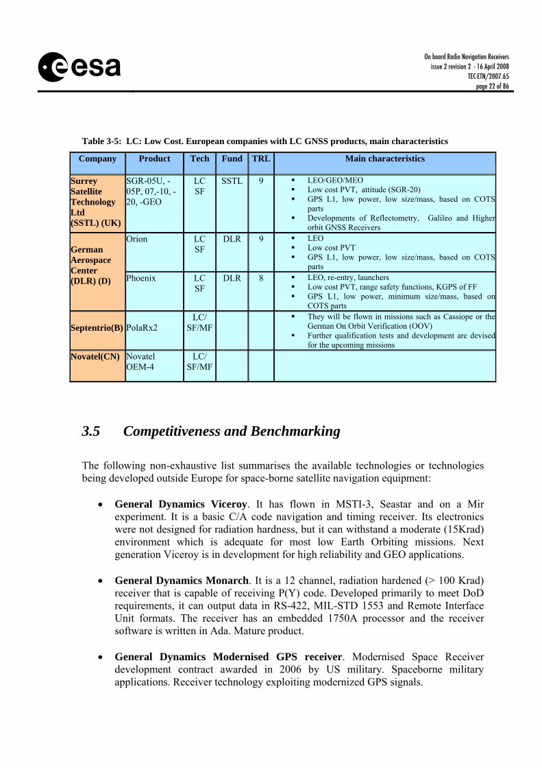
Table 3-5: LC: Low Cost. European companies with LC GNSS products, main characteristics
Company
Product Tech Fund TRL Main characteristics
Surrey Satellite Technology Ltd (SSTL) (UK)
SGR-05U, -05P, 07,-10, -20, -GEO
LC SF
SSTL 9 LEO/GEO/MEO Low cost PVT, attitude (SGR-20) GPS L1, low power, low size/mass, based on COTS
parts Developments of Reflectometry, Galileo and Higher
orbit GNSS Receivers Orion LC
SF DLR 9 LEO
Low cost PVT GPS L1, low power, low size/mass, based on COTS
parts
German Aerospace Center (DLR) (D) Phoenix LC
SF DLR 8 LEO, re-entry, launchers
Low cost PVT, range safety functions, KGPS of FF GPS L1, low power, minimum size/mass, based on
COTS parts Septentrio(B)
PolaRx2
LC/ SF/MF
They will be flown in missions such as Cassiope or the German On Orbit Verification (OOV)
Further qualification tests and development are devised for the upcoming missions
Novatel(CN) Novatel OEM-4
LC/ SF/MF
3.5 Competitiveness and Benchmarking The following non-exhaustive list summarises the available technologies or technologies being developed outside Europe for space-borne satellite navigation equipment:
• General Dynamics Viceroy. It has flown in MSTI-3, Seastar and on a Mir experiment. It is a basic C/A code navigation and timing receiver. Its electronics were not designed for radiation hardness, but it can withstand a moderate (15Krad) environment which is adequate for most low Earth Orbiting missions. Next generation Viceroy is in development for high reliability and GEO applications.
• General Dynamics Monarch. It is a 12 channel, radiation hardened (> 100 Krad)
receiver that is capable of receiving P(Y) code. Developed primarily to meet DoD requirements, it can output data in RS-422, MIL-STD 1553 and Remote Interface Unit formats. The receiver has an embedded 1750A processor and the receiver software is written in Ada. Mature product.
• General Dynamics Modernised GPS receiver. Modernised Space Receiver
development contract awarded in 2006 by US military. Spaceborne military applications. Receiver technology exploiting modernized GPS signals.

On board Radio Navigation Receivers
issue 2 revision 2 - 16 April 2008 TEC-ETN/2007.65
page 23 of 86
• Rockwell/Collins MAGR/S. The Miniature Airborne GPS Receiver/ Shuttle is the
Space Shuttle Receiver. This five-channel receiver is used to provide the Shuttle with real time navigation and timing. This is a P(Y) code receiver and NASA Johnson Space receiver is using the receiver in its fully secure mode.
• SS/L Tensor. The Space Systems /Loral Tensor is a radiation hardened (100Krad)
attitude, orbit and timing receiver. It has flown in the SSTI-Lewis spacecraft and several spacecraft in the SS/L Globalstar constellation.
• Trimble TANS Vector. It is a commercial terrestrial receiver that has been adapted
for use in space. Space-borne software was developed for this receiver through a partnership with engineers from Trimble, Stanford University, and GSFC/NASA. The receiver is somehow radiation soft with a tolerance of approximately 8Krad. Despite this, the receiver has supported low Earth missions for well over a year and in some cases 3 years. Problematic flights. No progress reported since 2002.
• JPL micro-GPS. It is a “bit grabber” with low mass (<0.5 kg) and volume
(<200cc), for post-processing on ground. No progress reported since 1999.
• SIGI Honeywell/Trimble/Collins/GSFC. The Space Integrated GPS/INS represents a new Inertial Navigation System for NASA’s Space Shuttle, International Space Station and Crew Return Vehicle. The INS consists of a Ring Laser Gyro, GPS receiver, inertial navigation computer and power supply mounted in a standard Embedded GPS INS housing.
• NASA/GSFC PiVoT. Low cost (<$100K) receiver for low cost missions. Based on
the commercial Plessey/Mitel chipset. Computations are performed using a StrongARM processor coupled with a radiation hardened Harris RTX micro controller to support GPS operations. Able to withstand moderate radiation environment (20 kRad). Weights 1.4 kg and consumes less than 10 watts. No progress reported since 2002.
• APL GNS. The Applied Physics Laboratory GPS Navigation System developed for
NASA/GSFC to support the Thermosphere-Ionosphere-Mesosphere-Energetic-Dynamics (TIMED).
• JPL/GSFC/Stanford GPS on a chip. Joint collaborative effort with JPL, NASA
GSFC and Stanford University as partners. GPS-on-a-Chip is being design to be modular with open architecture hardware and software design and developed to be flight qualified. GPS-on-a-chip supports multiple antennas, can be used as dual or single frequency and supports attitude determination, filtered navigation and timing. No progress reported since 1999.
• Broad Reach Engineering IGOR. Scientific instrument for GPS Occultation
measurements. Next generation Pyxis receiver due in 2008. Technology applied to LEO/MEO/ GEO navigation and attitude determination.
On board Radio Navigation Receivers
issue 2 revision 2 - 16 April 2008 TEC-ETN/2007.65
page 24 of 86
• ITT Space Systems. Modernised Space Receiver development contract awarded in 2006 by US military. Spaceborne military applications. Receiver technology exploiting modernized GPS signals.
• University of Texas. Development of COTS based receivers (e.g. Orion) in
collaboration with DLR (Germany). Low cost Navigation. Launch planned in 2007.
• JAXA (Japan). GPS Receiver flown on INDEX (2005). Low cost navigation. COTS based technology with relatively high radiation tolerance (20krad dose)
Table 3-6 summaries all the actors classified by the type of receiver (SF, MF, Low Cost), with information on leaderships for each application.

On board Radio Navigation Receivers
issue 2 revision 2 - 16 April 2008 TEC-ETN/2007.65
page 25 of 86
Table 3-6: Summary of all the actors classified by the type of receiver (SF, MF, Low Cost), with information on leaderships for each application.
Tech Company
Country Product Leadership
TAS-F France TS3000 1G TAS-I Italy Tensor
Astrium Germany Mosaic GNSS General
Dynamics USA Monarch
Rockwell/ Collins
USA MAGR/S
SS/L USA Tensor
Single Freq
SIGI USA SIGI
• Precise LEO PVT navigation: TS3000 1G, Tensor, Monarch
• GEO/GTO (high sensitivity tracking):
TS3000 1G, Mosaic GNSS • Attitude: TS3000 1G, Tensor, Mosaic
GNSS • Integration in on board avionics:
MosaicGNSS, SIGI.
TAS-F France TS3000 2G TAS-I Italy Lagrange TAS-I Italy Lagrange
ROSA AAE Austria IGPS A
(2008) AAE Austria IGPS B (2009)
AAE / SAAB
Aust/Swd GPS POD (2008)
AAE / SAAB
Aust/Swd GRAS
Astrium Germany LION Nav. APL USA GNS
Broad Reach Eng
USA IGOR
ITT Space Sys
USA New GPS Signals
Mult. Freq
General Dyn USA New GPS Signals
• Rendezvous, FF: TS3000 2G, IGSP B • Precise Orbit Determination: Lagrange,
GPSPOD • Militar (P-code, M-signals): ITT, GD • Science: LagrangeROSA, GRAS, GNS,
IGOR
SSTL UK SGR-xx DLR Germany Orion DLR Germany Phoenix
General Dyn USA Viceroy Trimble USA TANS Vector
NASA/GSFC
USA PiVoT
Low Cost
JAXA Japan GPS-INDEX
• Based on COTS: Phoenix, Viceroy • Based on COTS with modifications for
space: SGR-xx
All the above products have different technical characteristics. Comparing this range of products it shows that European technology is quite competitive for most of the products, being the leader in most of the technologies domains, and indeed Europe does supply space GNSS receivers for the US market.
On board Radio Navigation Receivers
issue 2 revision 2 - 16 April 2008 TEC-ETN/2007.65
page 26 of 86
The competitiveness of the European industry in the field has been achieved thanks to the support of technology development through ESA and other European agencies. Furthermore, European technology has benefited from the synergy, promoted by ESA, and exploited by industry between commercial and institutional markets.
3.6 Technology Trend Satellite navigation technology is a reality for terrestrial as well as for space-based users. The tremendous success of terrestrial satellite navigation market has attracted the companies with satellite navigation expertise to focus on the more profitable terrestrial-based applications. Consequently, these commercial companies are no longer interested in diverting their expertise on the relatively small space-based market. Only a few number of specialised companies covering the space applications. Main differences with the terrestrial receivers are the signal acquisition and tracking in high dynamic conditions (more challenging and the assumption on zenith pointing do not hold anymore), and the space radiation environment. This last point challenges the electronics while the power and mass restrictions are not as stringent as in terrestrial applications. This difference in electronics technology causes space qualified GNSS receiver evolutions to be much slower than those of terrestrial technology.
3.6.1 GENERAL TECHNOLOGY TRENDS This chapter addresses the GNSS Rx technology trends in general, including the terrestrial. Normally, innovations and technology evolutions are first on the terrestrial, and afterwards they are adapted to space.
3.6.1.1 Multi Constellations / Multi Frequency Receivers. New GNSS signals In view of the new signals available in the next years (modernised GPS and Galileo, and potentially Compass, SBAS,…), the performance of space-borne receivers will be significantly improved by adding the capability to track these new signals, especially in terms of accuracy (Galileo pilots, BOC, MBOC) and availability. These new signal will bring in particular: direct (versus-semi-codeless) tracking of multiple-frequency signals, lower tracking noise, enhanced multipath suppression, data & pilot codes, tri-carrier ambiguity resolution, more accurate broadcast ephemeris and integrity information. The larger number of satellites will also improve the geometric dilution of precision and the number of occultation and reflection events for scientific applications. The new signals will allow to reduced time to first fix due to availability of more signals with stronger signal power and optimised data format. These new signal will also promote the navigation in GEO due to improved signal strength.

On board Radio Navigation Receivers
issue 2 revision 2 - 16 April 2008 TEC-ETN/2007.65
page 27 of 86
Most of the benefits come at a notable increase in hardware cost and complexity. Compatibility with the new signals and the increased number of visible satellites will trigger the demand for increase in the processing power of correlators and micro-processors. With a total of four frequency bands (L1, L2, E5, E6) a variety of different receiver designs are possible. Likely candidates include an L1 single-frequency receiver as well as a L1+E5a dual-frequency receiver for tracking open service signals from up to 24 GPS and Galileo satellites. For an intermediate transition time, the need to support L2 signals of the GPS constellation might even result in tri-band receiver designs. Given the mass and power budgets of current space-grade GPS receivers, major efforts will, however, be required to keep the resulting receivers within reasonable limits.
3.6.1.2 Advance Microelectronics. Miniaturisation of Space Qualified GNSS Receivers
Advanced space microelectronics will lead to Single/dual chip solutions, allowing the navigation space receivers to: • Lower power/mass consumption, more complex architectures (multicorrelator, code-
phase and Doppler parallel acquisition) with improved performance (multipath, TTFF).
• Multi-frequency, multi GNSS receivers Besides that, the technology push given by the terrestrial technology development in the satellite field should be taken further into account by GNSS space-borne receiver manufacturers in order to bring a higher degree of miniaturisation and low power consumption also to space. This effort will be a significant contribution to the feasibility of mini and micro satellite missions. Power consumptions below 1 W appears desirable for onboard radio navigation receivers that are continuously operated. This requirement can presently only be met by COTS-based receivers such as the SGR-05U and Phoenix receivers. Further efforts will thus be required to achieve a similar performance with fully space hardened electronic components.
3.6.1.3 Software GNSS Receivers The use of Software Defined Radio (SDR) technology represents one of the most promising approaches for the next years. As opposed to hardware-defined systems, a SDR performs a substantial amounts of the signal processing in a general purpose computer (e.g. standard CPUs or DSPs), or a reconfigurable piece of hardware (e.g. FPGA chips). The objective of this concept is to develop a device that can process any new type of signal just by updating the software and/or the reconfiguration of e.g. the FPGA. The SDR approach for multifrequency GPS/Galileo receivers is promising, but the computational power is not yet available. In long-term, pure SW receivers are envisaged, running on standard CPUs with lower performances and less functionality (higher acquisition threshold, smaller number of channels and signals …)

On board Radio Navigation Receivers
issue 2 revision 2 - 16 April 2008 TEC-ETN/2007.65
page 28 of 86
3.6.1.4 New Multipath Mitigation Techniques Huge multipath effects occur on a generic LEO spacecraft, where GNSS antennas are surrounded by many large reflecting structures (payload, solar arrays, antenna accommodation). This degrades the performance in GNSS applications such as Orbit/Attitude determination, clock synchronisation and relative positioning between spacecraft (docking, rendezvous, and formation flying). New techniques for multipath detection and mitigation are expected to be developed within the next years, in three different areas: • Investigation in all domains: time, correlation, frequency, measurements & Signal. • Development of models: for static or quasistatic users • Characterisation of environment
3.6.1.5 Integration with other sensors and systems • Integration with other sensors: MEMS, INS. • Integration with wireless communications: Bluetooth, WLAN, UMTS, IEEEx. • AGNSS (AGPS) in space: The use of external data links can dramatically improve
TTFF, and can enable direct acquisition of weak signals..
3.6.1.6 Performance improvement. New signal and data processing algorithms
Acquisition & Tracking Algorithms: • Faster acquisition: fully parallel in code-phase and Doppler space. Block-processing
in frequency domain in pure SW Rx. In terms of robustness, the long cold-start time (typically 10-15 min) of many spaceborne GPS receivers represents a limiting factor. In particular, GPS receivers presently don’t lend themselves as safe-mode sensors that can deliver immediate position and/or attitude information after being switched on.
• Reduced Acquisition Threshold: for weak signal (-190dBW or lower in-door), increased coherent integration (use of Galileo pilots). Aiding (assisted through communication systems (ephemeris, almanac, Doppler))
• Reduce tracking threshold: Pilot in Galileo already enables tracking to 15dBHz. • One-shot acquisition: no tracking (real-time and off-line) for weak signals (in-door
and personal location) Interference detection and mitigation algorithms • Signal : optimize signal processing for interference mitigation

On board Radio Navigation Receivers
issue 2 revision 2 - 16 April 2008 TEC-ETN/2007.65
page 29 of 86
• Pulse-blanking: fast recovery Navigation processing: • Three frequencies algorithms for carrier phase based position techniques (TCAR),
as ambiguity resolution will become a comparatively simple, real-time and robust process, offering cm level. Much better multipath performance with carrier phase
• Development of Galileo local augmentations: Galileo Integrity with RAIM, differential services, pseudolites.
3.6.2 ONGOING ACTIVITIES IN RADIO NAVIGATION TECHNOLOGY IN EUROPE
This chapter provides an overview of the technologies activities on-going in Europe.
3.6.2.1 GNSS Receivers Modernisation. New GPS and Galileo signals. Thales Alenia Space (TAS-F) is developing under ESA contract and with the support of the CNES, a new receiver, Topstar 3000 G2. TAS-F is using their Topstar 3000 receiver and developing some new key components for its baseband processing and radio frequency front-end, allowing the receiver the tracking of the new GPS L1/L2C and pseudolite (1340 MHz) signals. Subcontractors are Norspace (Norway) and Syderal (Switzerland). This receiver will fly on-board the PROBA-2 mission by beginning of 2008. Austrian Aerospace (AAE) is developing, under ESA contract, a new receiver that incorporates new components and can be integrated in a flexible way, allowing the implementation of all types of GNSS receivers (GPS and GALILEO) with the characteristics of miniaturization, low-power consumption and multi-mission flexibility. The receiver will make the tracking of the new GPS L1/L5 signals. Subcontractors are Nemerix, Switzerland (Multiband Front-End) and Astrium, France (Mission). This development is expected to be completed in 2009. TAS-I is currently planning developments of next generation space receivers for on-board navigation based on dual/triple-frequency (L1, L2, E5/L5), dual-constellation GPS/Galileo and based on technologies that have been already proved on ground projects (Garda, Girasole and GRC) as for example porting of the channel correlators design (Galvani). Astrium (D) plans to go towards a LEON based next generation GNSS receiver, firstly based on the already existing AGGA-2 chip an later based on the new AGGA-3 chip. Astrium (D) is developing the LION Navigator GPS/Galileo Receiver. It is a scalable multi frequency receiver, which can be used as stand-alone unit or as slide-in module of an on-board computer

On board Radio Navigation Receivers
issue 2 revision 2 - 16 April 2008 TEC-ETN/2007.65
page 30 of 86
SSTL has prototype FPGA-based receiver architecture that has demonstrated signal tracking of both GPS and Galileo signals (using GIOVE-A BOC(1,1) signals). This is anticipated to be the core of future GNSS receivers for many applications. CNES has initiated an on-going R&D activity regarding the study and partial prototyping of a Galileo PRS spaceborne receiver.
3.6.2.2 Advance Microelectronics. Core Technologies evolutions ESA carried out the development of a GNSS based scientific instrument for METOP - GRAS. Although this instrument is in itself not directly useful for the navigation of a generic satellite platform, it should be noted that, once it is operational, the AGGA-2 chip, developed under this programme, has been a useful building block of the GNSS equipment. Currently, a new version, the AGGA-3, with capability to process the new GPS and Galileo signals is being developed by Astrium (D), expected to be available for 2008. This new component will be taken into account in future developments for space applications. NemeriX ASICs have been designed and tested to be radiation tolerance and to ensure the possibility for space qualification. The ASICs are currently under qualification (possibly under ESA contract) to be used in the SWARM mission.
3.6.2.3 Integrated GNSS Receivers. ESA/DLR, in a contract with Astrium (D) under ARTES programme, has developed the integration oft the MosaicGNSS receiver with a number of sensors to provide orbit and attitude determination at GEO orbit. The receiver has been extended with Star Sensors and Gyros for delivering an unified satellite state vector of position and attitude. Its performance has been verified in a real-time closed loop test bed. DLR has co-funded the development of relative navigation algorithms for the MosaicGNSS receiver.
3.6.2.4 Software GNSS Receivers The MosaicGNSS receiver is a first generation of a SW receiver In addition, an initiative has been launched at DLR/GSOC, aiming at the development of an independent GPS/Galileo receiver platform for space applications. The works are based on the Namuru II receiver board, a FPGA based dual-frequency GPS development platform designed and implemented by the Satellite Navigation & Positioning Laboratory (SNAP) within the School of Surveying & Spatial Information Systems, at the University of New South Wales. The key objectives of the conducted research and development work is the testing of novel acquisition concepts for high-dynamic applications, the design and implementation of tracking algorithms for the next generation GNSS signals as well as the
On board Radio Navigation Receivers
issue 2 revision 2 - 16 April 2008 TEC-ETN/2007.65
page 31 of 86
investigation of multicorrelator techniques for scientific applications such as reflectometry and scatterometry. Some other activities have also been done related with the use of pure SW receivers for space. The GREHDA project (GALILEO Software Receiver for High Dynamic Applications) is a joint activity of Carlo Gavazzi Space (Italy), Politecnico di Torino (Italy) and DLR/GSOC. It is funded by the Galileo Joint Undertaking under the 6th Framework Program. The study primarily addresses the design of Galileo receivers for space applications with limited financial and engineering budgets. TAS-I is involved in projects for the development of a SW Radio receiver (currently for ground applications with GJU and ASI) which may in future be ported to space technologies depending on availability of sufficient processing power. Clearly the use of space SW receivers will be a reality if low power, small size and rad hard suitable processors come on stream. CNES will start in 2007 a one-year R&D activity consisting in a early prototyping a GPS/GALILEO low cost software receiver for space applications.
3.6.2.5 Multipath Mitigation ESA initiated a project aiming at designing, implementing and validating a fully functional Neural Network (developed by TESA (F), ENAC (F), GMV (E) and UPC (E)) embedded into a GNSS navigation receiver prototype (ORUS SW receiver provided by M3S). Two different solutions were considered, in the signal processing and at observable level. Results show a good improvement obtained by the application of the NN algorithms both in signal domain (50% for the code tracking errors and 40% for phase tracking errors) and at observable level (up to 40% of relative mitigation, over the receiver outputs).
3.6.3 ONGOING ACTIVITIES IN RADIO NAVIGATION TECHNOLOGY OUTSIDE EUROPE
NASA has focuses on the use of GPS as an engineering sensor to support Earth and Science missions. To achieve these goals the Goddard Space Centre has been fostering government/university/industry partnerships. The elements of this programme include:
• GPS space borne receivers that satisfy the future spacecraft mission requirements. • The development of the techniques required to integrate this technology on
spacecraft in a cost effective manner. • The development of enhanced autonomy techniques such as autonomous orbit
control and formation flying. In short, the developments and vision of NASA could be summarised as follows:

On board Radio Navigation Receivers
issue 2 revision 2 - 16 April 2008 TEC-ETN/2007.65
page 32 of 86
• Long term programme leading the achievement of autonomous constellation control
in the near future and development of the virtual platform concept in 2012 • Long term programme leading to the GPS-on-a-chip in 2012, supported by the
requirements of future NASA’s Earth Observation and Science missions. • Partnerships between Agency, Universities and Industry • Maximum reuse and adaptation of commercial technologies (approach valid for
95% of all NASA’s Earth science and Space science missions)

On board Radio Navigation Receivers
issue 2 revision 2 - 16 April 2008 TEC-ETN/2007.65
page 33 of 86
4 MISSION NEEDS AND MARKET PERSPECTIVES
4.1 Application to Missions. GNSS-based Space Applications The GNSS applications, from the mission point of view, can be divided between those requiring an absolute knowledge of the spacecraft position and those only interested in the relative position of the spacecraft with respect to some other spacecraft(s). We therefore distinguish between absolute and relative navigation. The primary application of the absolute navigation is the position, velocity and time determination onboard LEO satellites. Other absolute navigation applications have also been study such as navigation of satellites in GEO or HEO orbits as well as the tracking of launch and re-entry vehicles. While GNSS receiver technology for LEO satellites has generally matured and reached a close-to-commercial status, the same does not apply for the latter category of applications. Receivers targeting at these type of mission are still experimental or have not yet been fully accepted by the relevant communities. Concerning relative navigation, the objective is the determination of relative position, relative velocity and relative time determination between spacecraft. Two applications are under this category, Formation Flight and Rendezvous missions, which are expected to have a significant importance during the coming years. In both cases, the main driver behind the use of GNSS receivers on board of spacecraft for navigation is the provision of real-time on-board support to the spacecraft to reduce mission costs (both by reducing the number of additional sensors on board and relaxing the requirements for ground control) and increase spacecraft’s autonomy. In addition to the navigation oriented applications discussed above, GNSS sensors are more and more employed as science instruments for geodetic and atmospheric research. In addition, some other applications make use of GNSS to support the payload in other aspects beyond navigation (time synchronisation, attitude).

On board Radio Navigation Receivers
issue 2 revision 2 - 16 April 2008 TEC-ETN/2007.65
page 34 of 86
HEO
LEO
GEO
GPS
HEO
LEO
GEO
GPS
Figure 4-1: Overview of the different satellite orbits where it is possible to use GNSS systems
4.1.1 ABSOLUTE NAVIGATION The introduction of GNSS into spacecraft for absolute positioning is helping to reduce the amount of extra sensors needed in modern missions. Depending on the type of mission different requirements need to be taken into account, which will impact the receiver design. Hereafter a presentation of the main applications is outlined. The following paragraphs summarise the main application areas.
4.1.1.1 Launchers GNSS receivers are of interest for ballistic vehicles, such as launchers, sounding rockets and re-entry capsules. Rocket launches are traditionally supported and monitored by ground based tracking radars. Due to the pronounced operations and maintenance cost of radar systems, GNSS based tracking systems are particularly attractive for scientific rocket launches with tight mission budgets. Other benefits of GNSS include the provision of both position and velocity information, the high accuracy and onboard availability of navigation data as well as the provision of a precise timing reference. These receivers should be designed to work in an uninterrupted manner withstanding high accelerations and vibrations. These high-level requirements already point to the use of custom designed tracking loops.
4.1.1.2 Re-entry navigation Since the characteristics of the atmospheric re-entry may limit the availability of GNSS signals along the descent (due to electromagnetic blackouts) it is mandatory to hybridise the GNSS receiver with other sensors. Receivers for this type of application must also feature fast (re)acquisition techniques to cope with loss of lock due to stress, blackouts and the fast change in the satellite geometry (from the geometry vehicle point of view).
On board Radio Navigation Receivers
issue 2 revision 2 - 16 April 2008 TEC-ETN/2007.65
page 35 of 86
4.1.1.3 LEO LEO missions represent the basic application of GNSS in space. The orbit is low enough to provide good visibility of four or more satellites, so the availability is high (since the LEO satellites are very close to the Earth’s surface in comparison to the GNSS orbits). This simplifies the overall design, since for instance, the antenna can be pointed to the zenith by design. Usually receivers in this category implement a dynamic navigation filter (Kalman filter) in order to propagate the PVT solution in case of satellite blackouts (for example if the satellite changes its attitude). In addition measurements are usually combined in the filter with orbit information, which can ease the (re)acquisition performance as well as bind the PVT errors. Typical accuracies for GNSS based real-time navigation of spacecraft in low Earth orbit are on the order of 10-20 m for kinematic single-frequency solutions. Using multiple frequency receivers and dynamical filtering the real-time navigation accuracy can further be improved to 1 m.
4.1.1.4 GEO The use of GNSS in GEO satellites has arisen basically because of the need of increasing S/C autonomy. That in turn can relax the requirements for the ground infrastructure. Since GEO satellites orbit well above GNSS satellites, direct visibility is usually achieved with GNSS satellites rising or setting above the earth. Even in that case, the number of visible satellites is usually below 4, so direct PVT computation is not possible. Because of that, GNSS receivers are used in combination with an orbital navigator. In addition the received signal is much weaker due to both the increased propagation path and the fact that the signal is not just received via the main antenna lobe but via secondary lobes (which broadcast 10-15 dB less power). If high-sensitivity techniques are used, which allow the acquisition/tracking as low as some 20 dBHz, it can be possible to overcome these problems and directly compute a PVT solution with errors in the range of 50-150 meters. The knowledge of the relative position of two or more GEO satellites can also ease the orbit management inside an assigned orbit slot, as well as increase the slot usability (by allowing more S/C inside a single slot) in real-time and reducing the ground infrastructure. The exploitation of GPS technology in the navigation of satellite flying in orbits beyond the GPS constellation has not yet gained full acceptance among spacecraft designers, manufacturers and operators. Despite the fact, that a number of feasibility studies as well as several successfully conducted flight experiments have demonstrated the feasibility and potential of the utilisation of GPS-based navigation in GEO and HEO applications, the technology has not been adopted in the market, at least up to now.

On board Radio Navigation Receivers
issue 2 revision 2 - 16 April 2008 TEC-ETN/2007.65
page 36 of 86
The future use of the Galileo signals in GEO needs further investigations. Based on the experience obtained with the SSTL receiver onboard the Giove-A experimental satellite seems that the transmitting radiation pattern does not offer a good coverage of the GEO orbit. The reason could be that the secondary lobes of the Galileo antennas have been designed to provide less gain than the GPS ones. Some scientific missions in HEO are aiming to use GNSS for orbit determination. For less demanding accuracies, operation only at perigee is considered. For higher accuracy scientific requirements (e.g. VLBI), all-orbit weak signal tracking, multiple frequencies and the fusion with inertial measurements is expected to yield high accuracies.
4.1.1.5 Precise LEO Navigation When using multifrequency receivers and navigation kalman filters provided with high order models of the perturbing forces, accuracies close to 30 cm in radial can be reached in LEO using broadcasted ephemeris.
4.1.2 RELATIVE NAVIGATION For many space applications the precise knowledge of an S/C position is not so important as its relative position to other S/Cs. The following applications represent an overview of uses of GNSS for relative navigation.
4.1.2.1 Rendezvous Relative GNSS (R-GNSS) is required on rendezvous missions. This means that the GNSS receiver shall be embarked on both satellites. GNSS data is normally transmitted one-way from the target spacecraft to the chase spacecraft to compute relative GNSS solution. In this application, the code or carrier phase measurements are differenced and filtered in order to provide relative position. These measurements are used from hundreds of kilometres to a distance of a few hundreds of meters after which other relative navigation techniques are used (radiolocation, laser, etc). For relative navigation of two spacecraft based on carrier-phase differential GPS (CDGPS), accuracies of down to 1 cm have been demonstrated in real-time hardware-in-the-loop simulations as well as offline analyses of actual flight data. The typical performances of the R-GNSS in LEO orbit are summarised below (Table 4-1). Two frequencies are needed to improve the time convergence of the estimator for the case of relative carrier phase processing (IAR). Ideally 3 frequencies (TCAR) are needed for real time processing with modernised GPS and Galileo. Accurate R-GNSS requires also choke ring antennas or equivalent to reduce the multi-path effects.
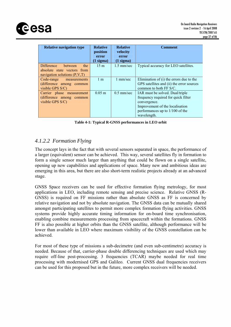
On board Radio Navigation Receivers
issue 2 revision 2 - 16 April 2008 TEC-ETN/2007.65
page 37 of 86
Relative navigation type Relative
position error
(1 sigma)
Relative velocity
error (1 sigma)
Comment
Difference between the absolute state vectors from navigation solutions (P,V,T)
15 m 1.5 mm/sec Typical accuracy for LEO satellites.
Code-range measurements (difference among common visible GPS S/C)
1 m 1 mm/sec Elimination of (i) the errors due to the GPS satellites and (ii) the error sources common to both FF S/C.
Carrier phase measurement (difference among common visible GPS S/C)
0.05 m 0.5 mm/sec IAR must be solved. Dual/triple frequency required for quick filter convergence. Improvement of the localisation performances up to 1/100 of the wavelength.
Table 4-1: Typical R-GNSS performances in LEO orbit
4.1.2.2 Formation Flying The concept lays in the fact that with several sensors separated in space, the performance of a larger (equivalent) sensor can be achieved. This way, several satellites fly in formation to form a single sensor much larger than anything that could be flown on a single satellite, opening up new capabilities and applications of space. Many new and ambitious ideas are emerging in this area, but there are also short-term realistic projects already at an advanced stage. GNSS Space receivers can be used for effective formation flying metrology, for most applications in LEO, including remote sensing and precise science. Relative GNSS (R-GNSS) is required on FF missions rather than absolute GNSS as FF is concerned by relative navigation and not by absolute navigation. The GNSS data can be mutually shared amongst participating satellites to permit more complex formation flying activities. GNSS systems provide highly accurate timing information for on-board time synchronisation, enabling combine measurements processing from spacecraft within the formations. GNSS FF is also possible at higher orbits than the GNSS satellite, although performance will be lower than available in LEO where maximum visibility of the GNSS constellation can be achieved. For most of these type of missions a sub-decimetre (and even sub-centimetre) accuracy is needed. Because of that, carrier-phase double differencing techniques are used which may require off-line post-processing. 3 frequencies (TCAR) maybe needed for real time processing with modernised GPS and Galileo. Current GNSS dual frequencies receivers can be used for this proposed but in the future, more complex receivers will be needed.

On board Radio Navigation Receivers
issue 2 revision 2 - 16 April 2008 TEC-ETN/2007.65
page 38 of 86
Slave(LEO)
Raw
Dat
a
Nav
Pla
nnin
gC
lock
Syn
chro
Com
man
ds
Master (LEO)Relative Nav Module
Master (LEO)Relative Nav Module
Slave(LEO)
Slave(LEO)
Figure 4-2: example of FF mission in LEO with master S/C
Near the Earth, the use of GNSS receiver is clear for the computation of the absolute and relative position, velocity, and time (PVT), as well as the coarse attitude. In case of FF missions not near the Earth, it will be used local transmitters/receivers of ranging signals for the computation of the relative position (loose and precision formation flying coarse metrology).
4.1.3 EARTH OBSERVATION AND SCIENTIFIC INSTRUMENTS In addition to the navigation oriented applications discussed above, GNSS sensors are more and more employed as science instruments for Earth Observation, geodetic and atmospheric research.
4.1.3.1 Precise Orbit Determination (POD) The high accuracy of this category (0.01 to 2 m) is obtained thanks to a differential GPS processing, using also on-ground GPS data collected on a geodetic points network (International Geodetic Service) for suppressing ionospheric delay and GPS orbit errors. An a posteriori filtering is necessary, as well as the use of a dual frequency receiver (to remove the ionospheric error). GPS measurements collected onboard the POD satellites have enabled the independent generation of high-fidelity gravity field models that notably outperformed the results derived from all previous space missions. For POD, dual-frequency operation is compulsory.
4.1.3.2 Geodetic and Atmospheric Research GNSS radio occultation measurements collected onboard these satellites enable a tomographic and low-latency monitoring of the troposphere and ionosphere for weather

On board Radio Navigation Receivers
issue 2 revision 2 - 16 April 2008 TEC-ETN/2007.65
page 39 of 86
forecasts and atmospheric studies. For both Radio Occultation (RO) dual-frequency operation is compulsory and local oscillator phase noise becomes an issue. While the use of GNSS measurements for gravimetry and atmospheric research is now a well established technology, new science opportunities emerge through the analysis of ground reflected GPS signals. The feasibility of these techniques has been demonstrated onboard the CHAMP satellite and with a dedicated GPS receiver onboard the SSTL’s UK satellite of the Disaster Monitoring Constellation (UK-DMC) and a variety of future space experiments has already been proposed by the science community. GNSS scatterometry can exclusively rely on single-frequency receivers, since measurements are based on the comparison of reflected signals with the same signals received via a direct path. However, resolution as well as link budget depend on the chip-length, thus, multi-frequency receivers allow for some freedom in choosing the surface-sampling resolution. For GNSS-altimetry multi-frequency capability allows for ionospheric correction and the adjustment of the measurement wavelength via differential-carrier techniques.
4.1.4 SUPPORT TO OTHER SUB-SYSTEMS
4.1.4.1 Attitude guidance In missions where the S/C needs to perform changes in its attitude to perform its tasks, the knowledge of the S/C position can help to decide when this attitude change needs to be carried out according to the mission’s requirements. This way, instantaneous orbit knowledge allows to derive the attitude guidance profile necessary to maintain an accurate Earth pointed orientation despite the potential orbit residual deformation (due e.g. to eccentricity). However, the use of GNSS receivers onboard LEO satellites for GNSS-based attitude determination suffers from short baselines and signal reflections at the spacecraft structure. Various successful flight demonstrations have reported achieved accuracies of 0.1° to 1° (SSTL under ESA activity), which are easily outperformed by other attitude sensors such as star cameras and optical gyros. Attitude capable GNSS receivers have therefore gained little attention, however, some interest remains in the aerospace community, as a GNSS receiver is required for most missions, and could either act as a back-up sensor or as an alternative to more expensive or bulky sensors on small satellites.
4.1.4.2 Synchronisation An additional application for GEO satellites is the synchronisation of the satellite’s payload to GNSS time. The on-board time determination obtained using a receiver can be quite accurate, without the need of an expensive on-board clock. For instance, when the receiver is able to provide a position with an accuracy of 30 meters, this means that it is also able to provide a time estimate of 100 ns or better.
On board Radio Navigation Receivers
issue 2 revision 2 - 16 April 2008 TEC-ETN/2007.65
page 40 of 86
4.1.5 EXPLORATION There are plans to put navigation and communications systems on planets under exploration, or even complemented with reduced satellite constellations around the Earth and Moon. These systems will provide navigation and attitude to a number of elements such as incoming and outgoing spacecraft, sample return missions, manned missions, asset location and tracking on the surface (probes, landers, rovers, balloons, equipment), and search and rescue. It is expected that these navigation signals on Mars will offer the possibility to study the atmosphere, as it is done today on the Earth (Mars atmosphere limb sounding of pressure & temperature). Technology demonstrators will be needed for rendezvous and docking (MSR precursors) and planetary and in-situ navigation and communication.
4.1.6 APPLICATION TO MISSIONS SUMMARY The present market for On Board Radio Navigation System is represented by the LEO applications, where the use of GNSS has opened a range of many possibilities. The constant demand to reduce the cost of satellite operation and the increasing complexity of new flexible Earth monitoring satellites opens practically the whole LEO satellite market to GNSS that is expected to become a standard unit in Attitude and Orbit Control Systems. Furthermore, the accuracy obtained in Precise Orbit Determination (POD) using on-board GNSS has opened a new era in science and earth observation satellite applications, such as formation flying, in-orbit interferometry, Earth magnetic and Earth gravity measurements (GOCE, SWARM, CHAMP, and GMES Sentinels). Other sophisticated uses of GNSS have generated new market niches such as, for example, the atmospheric sounding by GPS radio occultation (METOP, CHAMP), or the GNSS-reflectometry (PARIS). These types of scientific missions will take benefit of the new GNSS signals, specially the new GPS and Galileo, due to more interceptions and stronger signals, resulting in an improved performance. Formation Flying missions in LEO or in Earth orbit will use GNSS receiver as standard navigation sensor, providing coarse relative position. The GNSS receiver will guarantee the formation constellation deployment and assembly, and it will serve as collision avoidance equipment. Beyond the coverage of the GNSS constellations, Formation Flying satellites will use of GNSS-like transmitters/receivers for inter-satellite ranging in interplanetary missions or experiments placed at Earth-Sun Lagrange points (DARWIN, XEUS). Moon and Mars exploration will also require local navigation and communication systems, based on reduced GNSS-like constellations and/or in-situ equipments. These systems will support all type of orbital and surface operations, including Mars atmospheric studies and autonomous rovers. A GNSS receiver will be used on the ESA Automated Transfer Vehicle (ATV) for the Rendezvous and Docking operations to the International Space Station. GNSS receivers
On board Radio Navigation Receivers
issue 2 revision 2 - 16 April 2008 TEC-ETN/2007.65
page 41 of 86
are also used on launchers. Application of GNSS receivers on Geostationary Satellites is now an object of experimentation and is most likely to be developed in the mid term future. The characteristics of the Radio Navigation receivers will vary depending on the market segment to which they will be dedicated. Operational LEO satellite will require reliable systems with a life time in the range of 5 to 7 years, a modest but already significant radiation resistance (in the range of 15 to 50 krad). Scientific LEO satellites will require low cost solutions, and finally small micro-satellites (or even nano) will need low cost systems with low mass and power consumption with a modest radiation resistance (a few krad). On the other extreme of the market we may expect to see radio navigation systems for GEO where long life, high reliability and radiation hardness will be the driving requirements. So far, the distinction between the navigation and science applications is almost unambiguously reflected in the choice of single- versus multiple-frequency receiver technology. The vast numbers of GPS receivers in orbit are designed to provide navigation and timing information with an accuracy that is well compatible with the GPS Standard Positioning Service (SPS) and thus the use of single-frequency technology. Science applications, on the other hand, demand the availability of multiple-frequency measurements to measure (or eliminate) ionospheric path delays and to enable purely carrier-phase based navigation. In fact, high precision navigation marks the boundary between both receiver classes and a growing tendency to support these needs may be recognized in the receiver market.

a
TD ESA OB Radio Navigation
Receivers V2-2.doc
D O C U M E N T
Table 4-2: Review of GNSS spacecraft navigation applications and missions
Application Accuracy
Missions
Orbit Operational attitude
Freq GNSS based navigation solution
LEO 10-20 m PLEIADES, DMC, Earth Observation, GlobalStar, Proba-2, Demeter
LEO Mainly Earth pointing
SF PVT computation (snapshot or filtered).
GEO/GTO 50-150 m STENTOR, SkyLAN, IntelSat, GMP
GEO Mainly Earth pointing
SF Dedicated navigation filter (orbit propagator). Weak signal tracking. MF for stronger signals through Ionosphere
Precise LEO Nav 0.3-3 m SWARM, GMES LEO Mainly Earth pointing
MF Real-time on board navigation (navigation filter) Multifrequency
Re-entry 50-100 m ARD, Pre-X LEO to ground
Highly varying SF GNSS and IMU hybridisation
Absolute Navigation (Platform Rx)
Launcher 15 m ARIANE V, VEGA Ground to GTO
Potentially spinned
SF GNSS and IMU hybridisation
Rendezvous 1cm – 1m ATV LEO Mainly Earth pointing
MF Dedicated navigation filter for R-GNSS (use of PR or CP). TCAR for safety, autonomy missions. Relative
Navigation (Platform Rx)
FF LEO: cms GEO: 1 m
GRACE, PostGOCE, PRISMA, Proba-3, ASPICS, MagCon, MMS, TerraSAR-X, Cartwheel, Simbol-X
LEO HEO GEO
Mission depending
MF Dedicated navigation filter for relative navigation (use of carrier phase). TCAR for highly safety, autonomy and reliability missions.
POD Earth fields
0.01-2 m GOCE, SWARM, GMES Sentinels, CHAMP, GRACE
LEO Mission depending
MF Carrier phase and PR measurements filtering. The POD accuracies, rather in the cm range, are achieved by on-ground post processing. EO/Scientific
Instruments At. Sounding, Sea reflections
cms-1 m
METOP, CHAMP, PARIS, UK-DMC
LEO HEO
Mission depending
MF Carrier phase and PR measurements filtering
Attitude Guidance
0.1° - 1° PLEIADES, ROCSAT ALPHABUS
LEO GEO
Mission depending
SF PVT computation based on PR. Dedicated navigation filter based on CP for attitude.
Imaging 5 m PLEIADES, ROCSAT LEO Earth pointing SF Filtering of the PVT solution Support to other subsystems Synchro.
0.1 μs GEO telecom., GlobalStar LEO
GEO Earth pointing SF Calibration of internal propagation delays
Exploration Moon/Mars MSR, Aurora Dedicated nav/com systems, on-board and in-situ. SF: Single Frequency; MF: Multiple Frequency; PR: PseudoRange; CP: Carrier Phase
On board Radio Navigation Receivers Issue 2 revision 2 - 16 April 2008
TEC-ETN/2007.65 page 43 of 86
4.1.7 ONGOING ACTIVITIES IN SATELLITE NAVIGATION APPLICATIONS
4.1.7.1 Ongoing Activities in Satellite Navigation Applications in Europe
4.1.7.1.1 High Altitude Navigation
The use of GPS/GNSS at GEO has been discussed in many papers, but to date, only a few flight experiments have been flown and even fewer for which results have been made available for civil use. ESA/DLR, in a contract with Astrium (D) under ARTES programme, has developed the integration of the MosaicGNSS receiver with a number of sensors to provide orbit and attitude determination at GEO orbit. The receiver has been extended with Star Sensors and Gyros for delivering an unified satellite state vector of position and attitude. Its performance has been verified in a real-time closed loop test bed. DLR has co-funded the development of relative navigation algorithms for the MosaicGNSS receiver.
SSTL, in collaboration with the British National Space Centre (BNSC) and ESA, has developed and flown an experimental GPS receiver on board the GIOVE-A spacecraft. In addition to the primary payload, some secondary payloads are carried by the spacecraft. One of these is the SGR-GEO. Preliminary results have been very promising as 5 GPS signals have been tracked simultaneously. ESA in close collaboration with CNES and DLR have considered the feasibility of a network of pseudolites for high altitude space navigation (GTO/GEO, maybe beyond). At high altitudes the visibility of GPS satellites is limited and performance degrades. A considerable improvement could be obtained by tracking additional GPS like signal transmitted from ground beacons (pseudolites). Possible synergies with TT&C were also being looked at. A demonstration of the concept was intended by CNES, based on the Alcatel GPS TopStar 3000 receiver, on board a GEO satellite (Stentor mission). Unfortunately the launcher failed, and no further activities have taken place on this subject.
4.1.7.1.2 Precise LEO Navigation
When using navigation kalman filters provided with high order models of the perturbing forces, accuracies close to 30 cm in radial can be reached in LEO using broadcasted ephemeris, as it was demonstrated by CNES using the Topex-Poseidon on board GPS measurements, as inputs to the DIOGENE navigation filter. When using the precise ephemeris, supposed to be uploaded by TC, a real time positioning accuracy of 3 cm along the radial axis has been demonstrated.

On board Radio Navigation Receivers Issue 2 revision 2 - 16 April 2008
TEC-ETN/2007.65 page 44 of 86
4.1.7.1.3 Rendezvous
A truly autonomous demonstration of rendezvous using GPS was the NASA/OSC DART mission. SSTL’s GPS receiver was used by the Pegasus upper stage to guide the vehicle into a new orbit with precision. A navigation filter reset error in the vehicle caused excessive propellant usage, preventing transition to proximity mode and ultimately caused the collision of the participating spacecraft. Relative GPS technology is also used in the rendezvous between the ESA ATV and the ISS (code measurement), based on the GPS tensor receiver from Laben (TAS-I).
4.1.7.1.4 Formation Flying
DLR and CNES have demonstrated the feasibility of purely kinematic, high-precision relative navigation of formation flying spacecraft using real dual-frequency GPS measurements (DLR using the Least Squares Ambiguity Decorellation Adjustment (LAMBDA) method). Integer ambiguities can be resolved within several minutes for baseline lengths of 10-100 kilometers. The subsequent relative position fixes exhibit a typical 3D accuracy of 3-5 millimeters. GPS FF will be demonstrated by DLR in PRISMA. DLR has co-funded the development of relative navigation algorithms for the MosaicGNSS GPS L1 receiver CNES is also considering accurate relative positioning for operational formation flying in LEO using L1-C/A-L2C dual frequency GPS receivers. ESA and CNES have also developed technology for accurate formation flying in the outer space, manufactured by Thales Alenia Space (F/E) and GMV(E), and will be tested in the PRISMA and PROBA-3 missions. This is a key technology for the development of new future scientific and space exploration missions. Maximum reuse of GPS/EGNOS technology was intended, although specific issues (accuracy, frequency plan, near-far problem, etc.) were totally new. This product aims to cover various configurations of formation-flying missions up to 4 vehicles in the group, and with a navigation accuracy in the fine mode of 1 cm (distance) and 1° (line of sight).
4.1.7.1.5 Precise Orbit Determination
This is the case of the ESA missions GOCE, SWARM, and GMES Sentinels. GOCE is using a modified version of the Lagrange receiver (TAS-I) called SSTI (Satellite-To-Satellite-Instrument), and SWARM will use an instrument developed by AAE (A) based on the innovative GPS receiver developed with ESA. This is also exemplified by the German CHAMP satellite, which carries a BlackJack dual frequency GPS receiver.

On board Radio Navigation Receivers Issue 2 revision 2 - 16 April 2008
TEC-ETN/2007.65 page 45 of 86
4.1.7.1.6 Atmospheric Research. Radio Occultation (RO)
This is exemplified by the German CHAMP satellite, which carries a BlackJack dual frequency GPS receiver or by the ESA METOP mission, also with a dual frequency receiver (GRAS) developed by SE/AAE. More recently, the US/Taiwanese COSMIC constellation implements an operational system using GNSS occultations, with highly accurate and repeatable results.
4.1.7.1.7 Advanced Science Applications LEO satellite-based Global Navigation Satellite System (GNSS) receivers for bistatic altimetry/reflectometry and radio occultation measurements are of great interest as a possible component of future tsunami and Earth observation systems. The general idea is that densely spaced grids of sea surface heights with a few centimeters precision could be established fairly rapidly using multi-frequency GNSS receivers as add-on payload to independently planned Earth observation missions. The required performance of such a space-based monitoring system requires highly advanced GNSS receivers with improved algorithms and quasi real-time data processing capabilities (for example for a future space-based Tsunami Early Warning System). To support these activities, GFZ and DLR have recently launched a study for the development of a GNSS Occultation, Reflectometry and Scatterometry receiver (GORS) in the frame of GITEWS project. SSTL has a pioneering experiment to demonstrate the concept of GNSS reflectometry on the UK-DMC microsatellite. GNSS signals have been recovered off the ocean, ice and land to investigate the potential for GNSS Reflectometry as a powerful new remote sensing tool. SSTL is now identifying a follow-on flight opportunity that can demonstrate the next generation of instrument. ESA is performing several studies for a mission dedicated to the sea level monitoring based on reflected GNSS signals (PARIS concept).
4.1.7.1.8 GNSS signal simulators
ESA, CNES and some companies have GNSS constellation RF signal simulators developed by Spirent and Thales UK for generating modernised GPS, GLONASS and Galileo signals. These RF constellation simulators allow to simulate the RF signal received by one or several GNSS antennas onboard spacecrafts, single, dual or triple frequency. TAS-F and SMP(F) (November 2006 - February 2008 ) are developing under CNES contract a GPS/GALILEO flexible simulator.
4.1.7.1.9 Autonomous Orbit Control with GNSS

On board Radio Navigation Receivers Issue 2 revision 2 - 16 April 2008
TEC-ETN/2007.65 page 46 of 86
CNES has for long been involved in activities related to on-board navigation, as proved by the successful in-flight results obtained by the orbital navigators DIODE integrated with GPS on board the NASA spacecraft HETE2. CNES is running on the DEMETER satellite a flight demonstration of autonomous orbit control, launched in 2005. This micro-satellite carries on board a TOPSTAR 3000 G1 L1 12 channels GPS receiver for experimentation of GPS-based autonomous orbit control techniques. Autonomous orbit control provides simple ground segment and operations, and improves the orbit control accuracy. The results in orbit are very satisfactory, with a control that is very stable and accurate.
4.1.7.1.10 GNSS Attitude Determination
A GPS experiment on the UK satellite TOPSAT is currently demonstrating attitude determination using GNSS in comparison to horizon sensors and gyroscopes. Different attitude determination algorithms are being investigated, and multipath mitigation strategies tested.
4.1.7.2 Ongoing Activities in Satellite Navigation outside Europe JPL and NASA have implemented a service for transmitting real-time corrections to the GPS broadcast ephemeris via the TDRSS satellites. In combination with the Real-Time GIPSY navigation software, these corrections should enable decimeter position accuracies onboard a LEO satellite. This overcomes the main error contribution in space of the Signal-In-Space-Error (SISRE) of 1-1.5 m. This performance has so far only been validated in lab experiments and flight demonstrations are still pending. NASA is also supporting the development of technology for the use of GNSS at GEO and other high or highly elliptic orbits. NASA and DARPA continue to demonstrate rendezvous for autonomous servicing of expensive in-orbit assets, sample return and other applications.

On board Radio Navigation Receivers Issue 2 revision 2 - 16 April 2008
TEC-ETN/2007.65 page 47 of 86
4.2 Market Perspectives The number of LEO satellites expected to be launched in the period 2007 – 2016 is 480. From these 480, 140 are planned for a life span shorter than 5 years. From the 480, 30 can be identified in the ESA LTP and therefore considered as captive market. The number of orbital launches in this 10 years period can be approximate to 700 from which 100 European. The number of European scientific payloads would probably be lower than 5 (PARIS, METOP B and C and two more not yet defined). We can also suppose that each of the 2 European large Prime contractors involved in GEO activities would perform in this period one technology experiment in GEO. The above situation leads to an annual average potential market accessible to the EU industry of: • 25 low radiation tolerance units (€2,5m ) • 25 high radiation tolerance units (€25m ) • 1 one shoot special science or research unit In case of entry barriers in non-EU markets or in case of poor competitiveness of the EU industry, the European captive market can procure up to 15 units per year
4.3 European Strategic Interest The development and use of GNSS is fundamental for both commercial and scientific applications. The GNSS brings significant cost saving due to the broader on-board autonomy. This technology is important for the value that it adds to the competitiveness of European systems. In scientific applications, precise Radio Navigation technology opens new possibilities for high value scientific missions in Earth Science, Fundamental Physics, and Astronomy. Purchase from U.S. of state-of-the-art GPS receivers, as for many other advanced systems for Space and Defence, is often limited by export restrictions. It is therefore essential to ensure the availability of several European sources. Furthermore, in view of the Galileo System, it is of strategic relevance that Europe keeps the pace with the developments in Satellite Radio Navigation. Further more, the advent of new type of signals (Galileo, GPS&GLONASS modernised, Compass) and navigation concepts, like the virtual platform, give Europe an excellent opportunity to become world leader in this area.

On board Radio Navigation Receivers Issue 2 revision 2 - 16 April 2008
TEC-ETN/2007.65 page 48 of 86
4.4 Technology Requirements ESTER requirements which are related to on-board radionavigation receivers are listed in Table 4-3.
Table 4-3: ESTER Technology Requirement
ID Title TRT ROM Cost Priority T-36 GPS/GNSS Galileo Receiver 2009 Very High High T-275 Miniaturised radionavigation receiver 2010 High Low T-7753 Highly integrated avionics technologies 2009-2013 High High T-7833 In-orbit assembly with GNSS 2007 Low Low T-8052 User receiver technologies (RF, Digital)
miniaturisation 2010 Ultra High Medium
T-7691 System and Technology for Payloads exploiting GNSS Reflections
2008 High Medium
T-8042 GNSS Receivers for Space Applications 2010 Very High Low T-7727 Lunar & Mars short-range communication and
navigation system 2007 High Low
T-7723 Rendezvous and Docking/Capture 2008 - 2009 High High T-7719 Surface Mobility 2007 and 2009 High High T-7740 Entry, Descent and Landing Systems 2007-2010 High High T-7745 Autonomous navigation technologies for
exploration 2010-2015 High High
T-7764 Rovers & planetary surface instruments technology
2009-2010 High High
T-7831 Formation flying RF relative localisation 2008 High Low T-7977 FF testbed design 2010 Low High T-8057 Advanced GNC/Avionics Launcher Architecture 2010 Very High High T-8070 Autonomous Rendez Vous Docking Capture
Control Systems 2010 Very High High
T-7747 Formation flying technologies 2008-2012 Very High High T-8235 Radio occultation receiver instrument (GRAS-2)
for GPS/Galileo (/Compass) signals, including standard ASIC component
2011 Medium Medium
T-8246 GPS/Galileo receiver instrument for precise orbit determination.
2014 High Low
T-8302 Multi-mission High Integrity Hybrid Navigation (HiNAV) System
2012 High High

On board Radio Navigation Receivers Issue 2 revision 2 - 16 April 2008
TEC-ETN/2007.65 page 49 of 86
5 ROADMAP
5.1 Summary of the Mapping Meeting The following key recommendations were provided by the industry at the mapping meeting: • The scope shall include multi frequency receivers (>2 frequencies). They will be needed in
the future missions (compatibility between navigation systems). o Most of the missions would require the use of receivers with more than two
frequencies for risk reduction For most of the future LEO (or GEO) missions the use of single frequency receiver for absolute navigation will not be sufficient.
o The required accuracy can only be achieved with a dual frequency receiver (Ionospheric errors, etc…)
• ESA should promote the development of products with components subject to non European
export restrictions. European industry is confronted to non European single source supplies (EEE parts, e.g. power mosfets), in addition export restrictions could be applied to the technologies concerned in the near future. The competitiveness (in particular the cost) is an issue.
o Significant and continuous effort is required to improve and update the European product competitiveness according to the evolution of the technology and reference signals
o Industry recommends to reduce the dependence from US export licence(s) • The integration of all international current and future navigation systems in the current
strategy shall be assessed. Current navigation satellite systems are upgraded and new navigation satellite systems are developed. The use and interoperability of the additional systems have to be analysed and taken into account for the future GNSS receivers. (GPS and Galileo should be interoperability, GLONASS possible change from FDMA to CDMA, Chinese COMPASS/Beidou system, Indian IRNSS possible upgrade from a local to a global system)
• Interest to use GPS/GNSS in GEO/GTO. Using ground pseudolites, Chinese Beidou GEO
satellites, back antennas on navigation satellites. Operational advantages would be autonomous orbit determination (& control), less infrastructure on ground needed. Strong interest of US satellite manufacturers. Possible demonstration flight on SGEO (Artes 11).
• Industry recommends to keep an adequate funding according to the missions and to reduce
duplications o Competitiveness of European products under development has to be secured. o Focus efforts on commercial applications

On board Radio Navigation Receivers Issue 2 revision 2 - 16 April 2008
TEC-ETN/2007.65 page 50 of 86
o ESA funding shall be adequate to answer to the next generation of GPS/Galileo receiver and, baseband ASIC development and implementation
o Investments already undertaken (including internal industry funding) must be carefully considered
o Synergies between the various developments supported by European Agencies should be promoted
• Industry recommends to add a study (in the roadmap) to integrate all international current
and future navigation systems in the current strategy
5.2 Development Approach (Proposed future developments) Developments are proposed in the following strategic areas: 1. Development of new space receivers covering the new GNSS signals (modernised
GPS&GLONASS, Galileo, Compass,...). Miniaturisation of standard spaceborne GNSS receiver down to a level compatible with micro and nano-satellites, reducing size, power and mass. In medium term based on the new ASICS, and in longer term based on GNSS-on-a-chip. Realistically, most of the ESA and other European satellites in medium term will continue to be in the class of mini-satellites, with some micro-sat too.
2. Ensure the necessary core technology developments (RF FE and BB ASICs) order to make feasible the widest range of space-borne applications based on new GNSS system, i.e. modernised GPS signals, Galileo, Compass and Glonass. The important point is to keep developing core technologies (the chips) that are where the largest investment is required and therefore cannot be multiplied by the number of manufacturers. Europe has now an innovative RF FE (Nemerix) and a second under development (ChipIdea), and concentrates on the baseband (AGGA-4, as AGGA-3 seems to be discontinued) and on refinements of the RF parts.
3. Development of an Open Architecture Software satellite navigation receiver as an essential
tool for flexible receiver design (new signals, multiple missions). Technology link to the availability of suitable rad-hard processors (LEON series). The development of SW receivers shall be assessed due to limited processing capability at the moment. This technology area is focusing on the feasibility of the space software receiver. No development is envisaged in this activity
4. Developing techniques to extend the use of robust satellite navigation technology at
GEO/HEO/GTO altitudes and beyond (pseudolite ranging technology and infrastructure definition, integration with other sensors, high sensitivity processing techniques, inter-satellite GNSS-like ranging, etc.). Although radiation hard receivers exist, they are currently rather large and expensive, and reduction of price is needed.

On board Radio Navigation Receivers Issue 2 revision 2 - 16 April 2008
TEC-ETN/2007.65 page 51 of 86
5. Consolidation of formation flying and virtual platform navigation and control technologies,
both in the Earth proximity (GNSS based) and in Deep Space (autonomous ranging system). This technology area is treated in the Formation Flying metrology roadmap.
6. Consolidation on the use of GNSS technology for launchers (HiNAV architecture), to
support the avionics of AR5 and Vega Evolution as well as the specific requirements from CSTS. The objective is to implement a FM in FLPP-3 (starting in 2009).
7. Radio navigation technology to be developed in the frame of the AURORA programme: In-
situ location and navigation in solar system planets (like moon/mars), set of small GPS/Galileo-like payloads around the planet, probably on data-relay satellites, complemented with fixed surface beacons and/or terrestrial wireless techniques adapted to space; RF navigation sensors on orbiters, landers and rovers for rendezvous, re-entry, orbiting and surface operations. The RF relative navigation sensors area is addressed in the Formation Flying metrology roadmap.
This approach should be achieved by: • A high degree of harmonisation in ESA of different complementary technology areas
(AOCS, microelectronics, antennas, software, satellite navigation receiver and systems). • Active contribution to ESA R&D programmes (TRP, GSTP, and ARTES). • Active contribution to ESA Navigation Evolution Programme. • Maximisation of synergies in ESA between the technological developments and the ongoing
project efforts. • Harmonisation of efforts done by National Space Agencies and ESA.
5.2.1 PROPOSED ACTIVITIES NOTE: Non dependence aspects will be addressed for each activity.
5.2.1.1 AIM A: Low Cost Receivers A1. Low Cost GPS/Galileo Miniaturised Rx SSTL is developing a prototype FPGA-based receiver architecture that has demonstrated signal tracking of both GPS and Galileo signals (using GIOVE-A BOC(1,1) signals). This is anticipated to be the core of future GNSS receivers for many applications. Status: on-going. In 2002 roadmap

On board Radio Navigation Receivers Issue 2 revision 2 - 16 April 2008
TEC-ETN/2007.65 page 52 of 86
A2. Low Cost GPS/Galileo in a Chip Status: not yet funded. In 2002 roadmap A3. SGR-GEO SSTL, in collaboration with the British National Space Centre (BNSC) and ESA, has developed and flown an experimental GPS receiver on board the GIOVE-A spacecraft, the SGR-GEO. Preliminary results have been very promising as 5 GPS signals have been tracked simultaneously. Status: On-going. A4. SGR for Remote Sensing SSTL. Status: ? A5. GNSS low-cost receiver demonstrator CNES support. Study, prototyping and development of at least an EQM. Single frequency receiver (L1 or L5) Status: new
5.2.1.2 AIM B: High Reliability MF Receivers B1.1 Miniaturised GPS Rx (I) Austrian Aerospace (AAE) is developing, under ESA contract, a new receiver that incorporates new components and can be integrated in a flexible way, allowing the implementation of all types of GNSS receivers (GPS and GALILEO) with the characteristics of miniaturization, low-power consumption and multi-mission flexibility. The receiver will make the tracking of the new GPS L1/L5 signals. An intermediate receiver will track GPS L1/L2. Subcontractors are Nemerix, Switzerland (Multiband Front-End) and Astrium, France (Mission). This development is expected to be completed in 2009. Status: on-going. In 2002 roadmap. B1.2 Miniaturised GPS Rx (II) Thales Alenia Space (TAS-F) is developing under ESA contract and with the support of the CNES, a new receiver, Topstar 3000 G2. TAS-F is using their Topstar 3000 receiver and developing some new key components for its baseband processing and radio frequency front-end, allowing the receiver the tracking of the new GPS L1/L2C and pseudolite (1340 MHz) signals. Subcontractors are Norspace (Norway) and Syderal (Switzerland). This receiver will fly on-board the PROBA-2 mission by beginning of 2008. Status: on-going. In 2002 roadmap B2. L2C Studies Thales Alenia Space (TAS-F) under CNES contract. L2C studies in support to the Topstar 3000 G2.
On board Radio Navigation Receivers Issue 2 revision 2 - 16 April 2008
TEC-ETN/2007.65 page 53 of 86
Status: completed. In 2002 roadmap B3. GPS/Galileo Miniaturised Multi-Frequency Rx Development and testing of an EQM receiver, for supporting GNSS relative navigation in LEO orbits (rendezvous and FF missions). Platform receiver. Status: Not yet funded. In 2002 roadmap B4. Galileo PRS Spaceborne Receiver CNES has initiated an on-going R&D activity regarding the study and partial prototyping of a Galileo PRS spaceborne receiver. Studies of the global architecture, first partial prototyping of an acquisition board. Total 400 k€ - THALES-F. Status: On-going B5. LION Navigator. MF GPS/Galileo Receiver Astrium (D) plans to go towards a LEON based next generation GPS/Galileo receiver based on the new AGGA-3 chip. It is a scalable multi frequency receiver, which can be used as stand-alone unit or as slide-in module of an on-board computer. Capable of integration with INS. Status: new. B6. TAS-I GPS/Galileo Space Rx TAS-I is planning the development of next generation space receivers for on-board navigation based on dual/triple-frequency (L1, L2, E5/L5), dual-constellation GPS/Galileo and based on technologies that have been already proved on ground projects (Garda, Girasole and GRC) as for example porting of the channel correlators design (Galvani). The new generation onboard receiver is based on Nemerix’ RF chip + GALVANI. Status: new.
5.2.1.3 AIM C: High Reliability SF Receivers C1. Ultra-light GPS/Galileo Single Frequency Rx Development and testing of an EQM platform receiver for supporting GNSS absolute navigation in LEO/GTO/GEO orbits (AOCS, synchronisation) with emphasis on telecom missions. Status: new. C2. Multi-mission High Integrity Hybrid Navigation (HiNAV) Demonstrator Development of a multi-mission (ascent, rendezvous, re-entry, landing) Hybrid (IMU/GPS + complementary sensors) Navigation System (HiNAV) demonstrator. Applications: expendable launcher, reusable space transportation system, atmospheric re-entry vehicle Status: on-going C3. HiNAV System. Architecture Consolidation
On board Radio Navigation Receivers Issue 2 revision 2 - 16 April 2008
TEC-ETN/2007.65 page 54 of 86
Consolidation of the HiNAV functional, performance, safety and operational requirements for satisfying AR5 Evolution, Vega Evolution and Crew Space Transportation System (CSTS) navigation needs and generation of the HiNAV industrial file for the development of a Flight Model, including specifications, development, verification & validation approach, programmatic, cost, industrial organisation, etc Status: new C4. HiNAV System. EM Development and testing of the HiNAV Engineering Model (EM) that is functionally, mechanically, thermally and electrically representative of the Flight Model. Status: new C5. GPS/Galileo receiver coupled with an Inertial Measurement Unit for launchers Astrium (F/D). CNES support. Status: ongoing. C6. Feasibility of GNSS sensors for AOCS applications in GEO and higher altitudes In this study the feasibility of Global Navigation Satellite System (GNSS) receivers for the usage of AOCS orbit sensors in GEO and higher altitudes (lunar transfer) shall be investigated (autonomous orbit control, ephemeris generation and attitude control). The GNSSs to be considered shall be Galileo, GPS Block 2 and also the new GPS Block 3. The simulation environment shall be as realistic as possible and use HW-in-the-loop tests where suitable. Especially the performance improvement when using additionally to the main lobes also the side lobes shall be investigated as well as single and dual frequency use. The activity shall specify the final AOCS performance as well as the GNSS sensor, and should provide input for the future definition of the Galileo space service volume users. Status: new
5.2.1.4 AIM D: Core Technologies D1. GPS L1/L2/L5 RF FE Developed under activities: GPS/Galileo RF FE (D6.1 and D6.2) D2. Further development of the AGGA device. Feasibility & design C16831 - under EOEP : This activity builds up on the design of the AGGA-2 device, and further enhances it in three ways: 1) it replaces the Glonass signals by Galileo signals; 2) it integrates more functionality (e.g. digital down-conversion from Intermediate Frequency, LEON micro-processor, more baseband channels, etc); 3) it moves on to a more advanced silicium process. The output of this AGGA-3 has been a VHDL model. Status: ongoing. In 2002 roadmap D3. Development and testing of the AGGA-4 chipset,

On board Radio Navigation Receivers Issue 2 revision 2 - 16 April 2008
TEC-ETN/2007.65 page 55 of 86
Under EOEP: The objective of this activity is to update the AGGA-3 VHDL model with the latest Galileo signals, including the processing with Linear Shift registers and memory-based registers. Compatibility with COMPASS will also be looked at. The design shall be optimised in order to allow the largest number of GNSS possible in the device. The output will be FPGA and ASIC components, including a preliminary verification. ESA clarified at the roadmap meeting that the TN with the AGGA4 signal specifications is to be attached to the SOW expected to be issue by 1Q08. AGGA4 will not cover E6. Status: not yet funded. In 2002 roadmap D4. GNSS Space Rx Studies Mapping between the new GNSS signals and space receivers, according to different type of applications. Definition of preliminary architecture and performance. CNES is ready to communicate results of D9 (finished by beginning 08). The ESA study is complementary to the one being done by CNES, since it will focus on the new signals from COMPASS, GLONASS and other regional systems. Status: not yet funded. In 2002 roadmap D5. GPS/GALILEO Miniaturised Space Receiver (GAMIR), GSTP. The objective of this activity is to develop and test a GPS/Galileo miniaturised Space Receiver in Elegant Breadboard form, including a Baseband ASIC and Radio Frequency Front-End, and capable of performing the whole signal processing (acquisition / tracking loops), data demodulation and deformating, and navigation solution including Positioning / Velocity / Time (PVT). ESA will not impose any technical solution but the needs. Status: funded and in planning. In 2002 roadmap D6.1 GPS/Galileo RF FE (I) FE chip-set developed by Nemerix (CH) under ESA contract with AAE (A) as prime. The chip-set comprises 2 ASICs, an RF front-end referred to as G3RF (NJ1007R) and an AD converter ASIC (NJ1017CR), named G3AD. The chip is manufactured in a 0.35 μm SiGe process. The G3RF is in fact able to receive all GPS, Galileo and GLONASS signals up to a bandwidth of 25 MHz. Both ASICs have been designed by NemeriX as radiation tolerance by design. Status: ongoing. In 2002 roadmap D6.2 GPS/Galileo RF FE (II) Within an ESA contract, ChipIdea (P) is developing a monolithic Galileo/GPS front-end ASIC for GNSS receivers. The chip allows multiple band reception (E1 / L1 / L2 / E5a / E5b / E6) with simultaneous reception of: L1/L2 or L1/E6 or L1/E5a or L1/E5b or L1/E5a+E5b. (See also micro-electronics dossier). Status: ongoing. In 2002 roadmap D6.3 GPS/Galileo RF FE (III) Under ESA contract, IMEC (B) is developing a high-performance low-power front-end for multi-band satellite navigation systems in space. The signal reception is performed on an upper band for GPS L1 and GLONASS L1 and on a lower band for GPS L2, GPS L5, and GLONASS L2. (See also micro-electronics dossier).

On board Radio Navigation Receivers Issue 2 revision 2 - 16 April 2008
TEC-ETN/2007.65 page 56 of 86
Status: Activity cancel. In 2002 roadmap D7. Techniques for GNSS navigation at High Orbits. Study & Demonstrator Study and demonstrator of new techniques for GNSS navigation at GEO and high orbits. The innovation is based on the techniques being used on ground for indoor navigation, mainly by using high sensitivity signal processing algorithms and by integration with other sensors. Status: new D8. GPS-Rx SW Elements. 2 activities AAE(A) under ASAP funding. Activities are integral part of durable Receiver SW-architecture (platform), forming the backbone of the on-board receiver product line: Multi-mission capability; Multi-application capability Status: ongoing. D9. GNSS Use for Space Missions Mapping between the new GNSS signals and space receivers. Internal CNES phase 0 study. The goals of the phase 0 are the following: collect the needs in positioning and timing of the future space vehicles and launchers after 2012 and identify and compare technical solutions to these needs. The outputs will be a clear and structured vision of the needs and roadmaps for future Onboard GNSS receiver development. Status: ongoing. D10. GPS L1/L2 Antenna & LNA for POD Saab Space (S) under the ESA Swarm mission. Status: ongoing. D11. GNSS Attitude Determination Experiment SSTL. Different attitude determination algorithms are being investigated, and multipath mitigation strategies tested. A GPS experiment on the UK satellite TOPSAT is currently demonstrating attitude determination using GNSS in comparison to horizon sensors and gyroscopes. Status: ongoing. D12. Core Signal Processing of future GNSS signals SSTL. Status: ongoing.
5.2.1.5 AIM E: Earth Observation & Scientific Instrument E1. GPS POD Instrument The objective of this activity is to develop a miniaturise EQM GPS L1/L2 POD instrument based on the AGGA-2 and the Nemerix ASICs. Status: funded and in planning.

On board Radio Navigation Receivers Issue 2 revision 2 - 16 April 2008
TEC-ETN/2007.65 page 57 of 86
E2. Enhanced GPS/Galileo Miniaturised POD Instrument The objective of this Activity is to enhance the hardware of a GPS / GALILEO Space Receiver to be equipped with an AGGA-4 ASIC up to Engineering Qualification Model (EQM), and also to further improve the relevant application functionality in order to allow Precise Orbit Determination (POD). Status: new E3. Radio Occultation Rx Instrument (GRAS-2) for new GNSS systems - parallel studies Two parallel studies under EOEP. The objective of this activity is to use a GPS / GALILEO Space Receiver based on the AGGA-4 ASIC and develops the necessary functionality for a Radio Occultation receiver Instrument. Status: new E4. PARIS Airborne Demonstrator Astrium (UK). Status: ongoing. E5. PARIS Technology Demonstrator (EBB) Status: new E6. ROSA (Radio Occultation Sounder for Atmosphere) Funded by ASI. Development of an integrated GPS receiver for scientific space applications in the field of the atmospheric sounding by radio occultation of GPS signals. The instrument main features consist of accurate measurements of pseudorange and integrated Doppler (raw data) at dual-frequency from GPS satellites. In addition, the instrument is able to determine position, velocity and time using GPS signals. The instrument will be embarqued on board Oceansat-2 (ISRO). Status: ongoing.
5.2.1.6 AIM F: Software Based Receivers Aim F activities focus on the feasibility of the space software receiver. No development is envisaged in this area. F1. GNSS Space Software Receiver. Prototype Demonstrator Feasibility study and prototype of an Open Architecture Software satellite navigation receiver as a tool for flexible receiver design and low cost technology. Technology linked to the availability of suitable rad-hard processors (LEON series). Status: new F2. GPS/Galileo low-cost software receiver
On board Radio Navigation Receivers Issue 2 revision 2 - 16 April 2008
TEC-ETN/2007.65 page 58 of 86
CNES started in 2007 a one-year R&D activity consisting in an early prototyping a GPS/GALILEO low cost software receiver for space applications. Single frequency L1 or L5. TAS-F. Status: on-going F3. TAS-I GPS/Galileo software receiver TAS-I is involved in projects for the development of a SW Radio receiver (currently for ground applications with GSA and ASI) which may in future be ported to space technologies depending on availability of sufficient processing power. Status: on-going
5.2.1.7 AIM G: Exploration Navigation Technologies G1 & G2. In-situ Nav/Com System. Two parallel studies This activity define and explore the feasibility of a planetary navigation and communications system such a system, with the scope to support the surface exploration of the solar system, and in particular the Moon, the planets (Mars) and even asteroids, based on existing and new technologies identified by NASA and ESA, NASA and other space faring nations. The system should support both surface and orbital/transfer operations. Status: ongoing G3. In-situ Nav/Com System. Technology Demonstrator This activity shall demonstrate the feasibility of a planetary navigation and communications system such a system selected in the previous study. A prototype system with several assets should be developed that is capable of demonstrating video transmission and app. 10m navigation capability in Mars like environment (eg. Crater). All this within one single signal design. Status: new G4. GNSS Navigation on the Moon To support future exploration of Moon surface, GPS and Galileo satellites could be used if receivers are capable of acquisition and tracking in the order of 15 dBHz signal to noise ratios. Today latest developments show that these values are feasible. For GPS the space service volume has been defined and it can be expected for the Moon as well. This study should investigate the possible techniques to navigate on the Moon (aided with other technologies) based on this concept. Status: new
5.2.1.8 AIM H: Technology Test Benches H1. FF GNSS LEO Test Bed Status: ongoing
On board Radio Navigation Receivers Issue 2 revision 2 - 16 April 2008
TEC-ETN/2007.65 page 59 of 86
H2. Flexible RF GNSS constellation simulator CNES activity. 8 channels simulator compatible with GPS III, Galileo and Glonass G1 and G2. Status: ongoing H3. GNSS Signal Generator Status: ongoing

On board Radio Navigation Receivers Issue 2 revision 2 - 16 April 2008
TEC-ETN/2007.65 page 60 of 86
5.2.2 ACTIVITIES LINK TO REQUIREMENTS
Figure 5-1: activities link to requirements
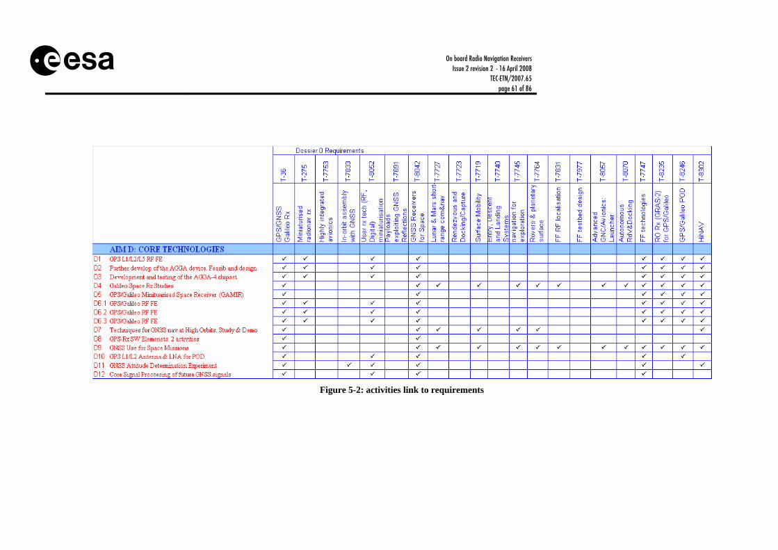
On board Radio Navigation Receivers Issue 2 revision 2 - 16 April 2008
TEC-ETN/2007.65 page 61 of 86
Figure 5-2: activities link to requirements

On board Radio Navigation Receivers Issue 2 revision 2 - 16 April 2008
TEC-ETN/2007.65 page 62 of 86
Figure 5-3: activities link to requirements

On board Radio Navigation Receivers Issue 2 revision 2 - 16 April 2008
TEC-ETN/2007.65 page 63 of 86
5.3 Schedule The following figures provide the roadmap proposal for 2007-2012.
Figure 5-4: roadmap schedule proposal for 2007-2012. AIM A, B, C. Green: funded and running, Red: new
ID Task Name
2 AIM_A: LOW COST RECEIVERS3 A01: Low Cost GPS/Galileo Minitaurised Rx4 A02: Low Cost GPS/Galileo in a Chip5 A03: SGR-GEO6 A04: SGR for Remote Sensing7 A05: GNSS low-cost receiver demonstrator 8 AIM_B: HIGH RELIABILITY MF RECEIVERS9 B1.1: Miniturised GPS Rx10 B1.2: Miniturised GPS Rx11 B02: L2C Studies12 B03: GPS/Galileo Miniturised MultiFrequncy Rx13 B04: Galileo PRS spaceborne receiver14 B05: LION Navigation. MF GPS/Galileo Receiver15 B06: TAS-I GPS/Galileo Space Rx16 AIM_C: HIGH RELIABILITY SF RECEIVERS17 C01: Ultralight GPS/Galileo Single Frequency Rx18 C02: Multi-mission High Integrity Hybrid Navigation19 C03: HiNAV System. Architecture Consolidation20 C04: HiNAV System. EM21 C05: GPS/Galileo receiver coupled with an Inertial 22 C06: Fsblt of GNSS for AOCS in GEO and higher
H1 H2 H1 H2 H1 H2 H1 H2 H1 H2 H1 H2 H1 H2 H1 H2 H1 H2 H1 H2 H1 H2 H1 H22003 2004 2005 2006 2007 2008 2009 2010 2011 2012 2013 2014

On board Radio Navigation Receivers Issue 2 revision 2 - 16 April 2008
TEC-ETN/2007.65 page 64 of 86
Figure 5-5: roadmap proposal for 2007-2012. AIM D. Green: funded and running, Red: new
ID Task Name
23 AIM_D: CORE TECHNOLOGIES24 D01: GPS L1/L2/L5 RF FE25 D02: Further development of the AGGA device. Fea26 D03: Development and testing of the AGGA-4 chipse27 D04: GNSS Space Rx Studies28 D05: GPS/Galileo Minituarised Space Receiver (GA29 D6.1: GPS/Galileo RF FE30 D6.2: GPS/Galileo RF FE31 D6.3: GPS/Galileo RF FE32 D07: Techniques for GNSS navigation at High Orbits33 D08: GPS-Rx SW Elements. 2 activities34 D09: GNSS Use for Space Missions35 D10: GPS L1/L2 Antenna & LNA for POD36 D11: GNSS Attitude Determination Experiment37 D12: Core Signal Processing of future GNSS signals
H1 H2 H1 H2 H1 H2 H1 H2 H1 H2 H1 H2 H1 H2 H1 H2 H1 H2 H1 H2 H1 H2 H12003 2004 2005 2006 2007 2008 2009 2010 2011 2012 2013 2014

On board Radio Navigation Receivers Issue 2 revision 2 - 16 April 2008
TEC-ETN/2007.65 page 65 of 86
Figure 5-6: roadmap proposal for 2007-2012. AIM E, F, G, H. Green: funded and running, Red: new
ID Task Name
38 AIM_E: EARTH OBSERVATION/SCIENTIFIC INSTRUM39 E01: GPS POD Instrument40 E02: GPS/Galileo Minituarised POD Instrument41 E03: Radio Occultation Rx Instrument (GRAS-2) for 42 E04: PARIS Airborne Demonstrator43 E05: PARIS Technology Demonstrator (EBB)44 E06: ROSA (Radio Occultation Sounder for Atmosph45 AIM_F: SW BASED RECEIVERS46 F01: GNSS Space Sw Receiver. Prototype Demonst47 F02: GPS/Galileo low-cost software receiver48 F03: TAS-I GPS/Galileo software receiver49 AIM_G: EXPLORATION NAVIGATION TECHNOLOGIE50 G1.1: In-situ Nav/Com System. Study51 G1.2: In-situ Nav/Com System. Study52 G02: In-situ Nav/Com System. Technology Demonst53 G03: GNSS Navigation on the Moon54 AIM_H: TECHNOLOGY TEST BENCHES55 H01: FF GNSS LEO Test Bed56 H02: Flexible RF GNSS constellation simulator57 H03: GNSS Signal Generator
H1 H2 H1 H2 H1 H2 H1 H2 H1 H2 H1 H2 H1 H2 H1 H2 H1 H2 H1 H2 H1 H2 H12003 2004 2005 2006 2007 2008 2009 2010 2011 2012 2013 2014

On board Radio Navigation Receivers Issue 2 revision 2 - 16 April 2008
TEC-ETN/2007.65 page 66 of 86
Priority (UPriority (C)(H, M, L) (H, M, L) Approv. Additional Type Company Current Target
R AIM A: LOW COST RECEIVERSA01 Low Cost GPS/Galileo Miniaturised Rx ? BNSC? ? SSTL (UK) Company co-funding 4 6A02 Low Cost GPS/Galileo in a Chip L M ? Natl ? SSTL(UK)?, DLR(G)? Company co-funding 4 6A03 SGR-GEO ? BNSC? ? SSTL (UK) Company co-fundingA04 SGR for Remote Sensing ? BNSC? ? SSTL (UK) Company co-funding 4 6A05 GNSS low-cost receiver demonstrator ? CNES OC 4 6
AIM B: HIGH RELIABILITY MF RXsB1.1 Miniaturised GPS Rx 3000 ARTES OC AAE(A)/Nemerix(CH) GPS L1/L2 (completed 07)
& GPS L1/L5 (waiting AGGA-3)
3 7
B1.2 Miniaturised GPS Rx 2300 ARTES OC TAS (F) /NordSpace (N) TS3000 G2, GPS L1/L2C (L5 prototype)
3 7
B02 L2C Studies 600 CNES DN TAS (F) Support to TS3000 G2 1 3B03 GPS/Galileo Miniaturised MultiFrequency Rx M H 2000 GSTP OC EQM. Platform. Relative
navigation (FF, RdV)3 6
B04 Galileo PRS spaceborne receiver 400 CNES OC TAS (F) 1 4B05 LION Navigation. MF GPS/Galileo Receiver 1500 DLR DN Astrium (F/G) AGGA3/INS based.
Company co-funding?7/8
B06 TAS-I GPS/Galileo Space Rx ? ASI? TAS-I Company co-funding?AIM C: HIGH RELIABILITY SF RXs
C01 Ultralight GPS/Galileo SingleFrequency Rx M H 2000 ARTES OC EQM, Platform. Abs nav, AOCS, Sync (LEO/GEO/GTO)
3 7
C02 Multi-mission High Integrity Hybrid Nav(HiNAV) Demonstrator
600 TRP OC Astrium (F/G) GNSS/INS for Launcher & Re-entry
2 4
C03 HiNAV System. Architecture Consolidation H H 250 TRP DN Astrium (F/G) 2 4C04 HiNAV System. EM M M 2500 GSTP/
FLPP-3OC Assumed to be included in
FLPP-34 6
C05 GPS/Galileo rx coupled with IMU for launchers ? CNES ? Astrium (F/G) ?C06 Fsblt of GNSS for AOCS in GEO and higher H H 200 TRP OC 1 3
TRL levelRemarkBudget (kEuro) Programme Proc. PolicyProposed Programme
5.4 Costs The following figures provide the costs proposal for 2007-2012. KEYGreen Funded and runningOrange Funded and in planningRed New funding request
Figure 5-7: roadmap costs proposal for 2007-2012. AIM A, B, C.

On board Radio Navigation Receivers Issue 2 revision 2 - 16 April 2008
TEC-ETN/2007.65 page 67 of 86
KEYGreen Funded and runningOrange Funded and in planningRed New funding request
Figure 5-8: roadmap costs proposal for 2007-2012. AIM D.
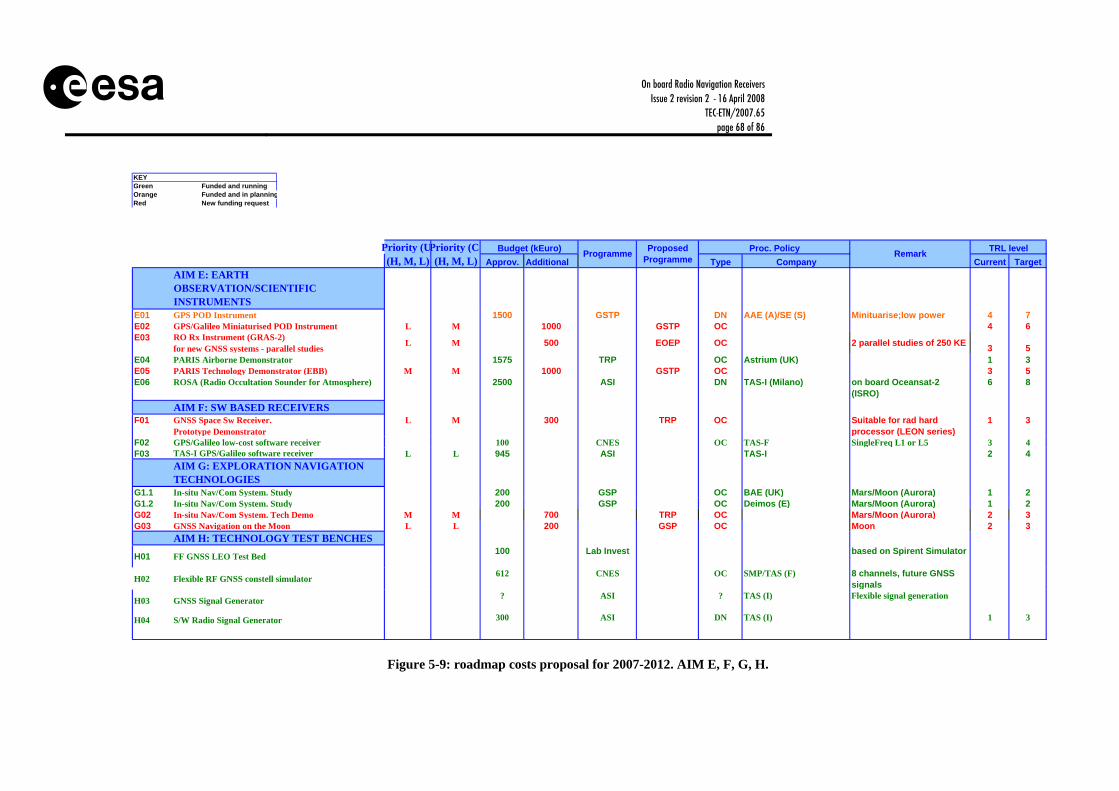
On board Radio Navigation Receivers Issue 2 revision 2 - 16 April 2008
TEC-ETN/2007.65 page 68 of 86
Priority (UPriority (C)(H, M, L) (H, M, L) Approv. Additional Type Company Current Target
AIM E: EARTH OBSERVATION/SCIENTIFIC INSTRUMENTS
E01 GPS POD Instrument 1500 GSTP DN AAE (A)/SE (S) Minituarise;low power 4 7E02 GPS/Galileo Miniaturised POD Instrument L M 1000 GSTP OC 4 6E03 RO Rx Instrument (GRAS-2)
for new GNSS systems - parallel studies L M 500 EOEP OC 2 parallel studies of 250 KE 3 5E04 PARIS Airborne Demonstrator 1575 TRP OC Astrium (UK) 1 3E05 PARIS Technology Demonstrator (EBB) M M 1000 GSTP OC 3 5E06 ROSA (Radio Occultation Sounder for Atmosphere) 2500 ASI DN TAS-I (Milano) on board Oceansat-2
(ISRO)6 8
AIM F: SW BASED RECEIVERSF01 GNSS Space Sw Receiver.
Prototype DemonstratorL M 300 TRP OC Suitable for rad hard
processor (LEON series)1 3
F02 GPS/Galileo low-cost software receiver 100 CNES OC TAS-F SingleFreq L1 or L5 3 4F03 TAS-I GPS/Galileo software receiver L L 945 ASI TAS-I 2 4
AIM G: EXPLORATION NAVIGATION TECHNOLOGIES
G1.1 In-situ Nav/Com System. Study 200 GSP OC BAE (UK) Mars/Moon (Aurora) 1 2G1.2 In-situ Nav/Com System. Study 200 GSP OC Deimos (E) Mars/Moon (Aurora) 1 2G02 In-situ Nav/Com System. Tech Demo M M 700 TRP OC Mars/Moon (Aurora) 2 3G03 GNSS Navigation on the Moon L L 200 GSP OC Moon 2 3
AIM H: TECHNOLOGY TEST BENCHES
H01 FF GNSS LEO Test Bed 100 Lab Invest based on Spirent Simulator
H02 Flexible RF GNSS constell simulator 612 CNES OC SMP/TAS (F) 8 channels, future GNSS signals
H03 GNSS Signal Generator ? ASI ? TAS (I) Flexible signal generation
H04 S/W Radio Signal Generator 300 ASI DN TAS (I) 1 3
Remark TRL levelBudget (kEuro) Programme Proposed Programme
Proc. Policy
KEYGreen Funded and runningOrange Funded and in planningRed New funding request
Figure 5-9: roadmap costs proposal for 2007-2012. AIM E, F, G, H.
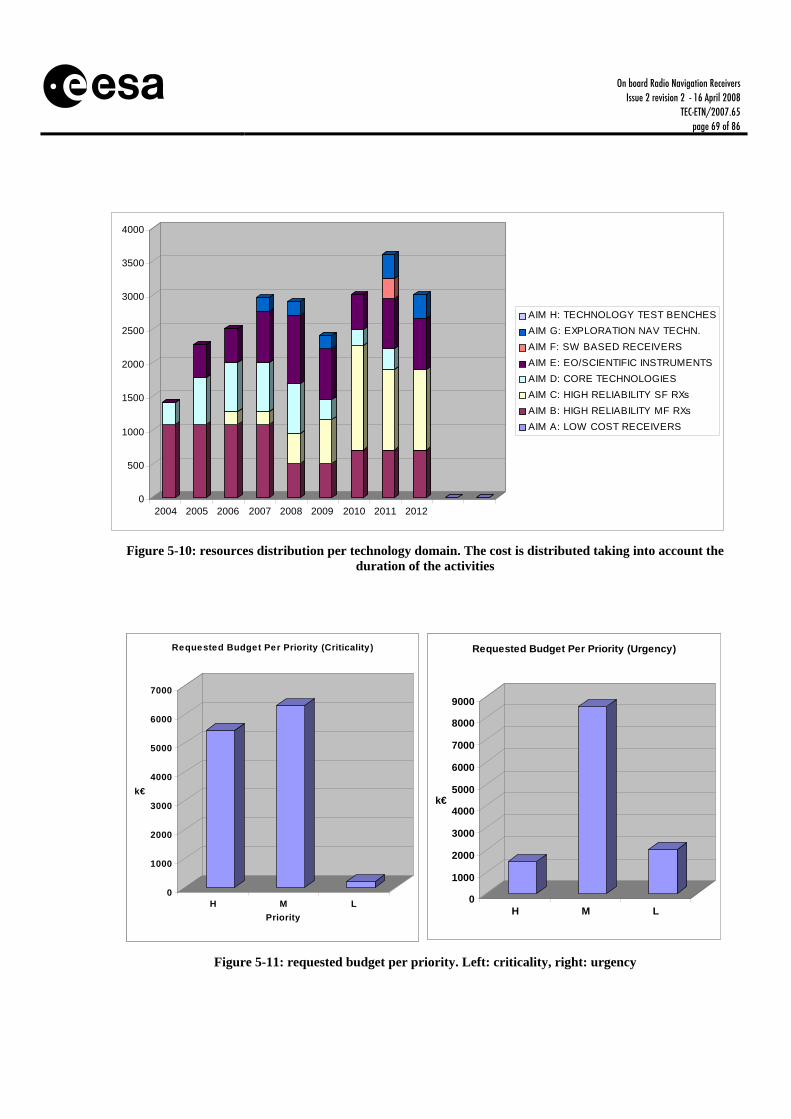
On board Radio Navigation Receivers Issue 2 revision 2 - 16 April 2008
TEC-ETN/2007.65 page 69 of 86
Figure 5-10: resources distribution per technology domain. The cost is distributed taking into account the
duration of the activities
0
1000
2000
3000
4000
5000
6000
7000
k€
H M LPriority
Requested Budget Per Priority (Criticality)
0
1000
2000
3000
4000
5000
6000
7000
8000
9000
k€
H M L
Requested Budget Per Priority (Urgency)
0
1000
2000
3000
4000
5000
6000
7000
k€
H M LPriority
Requested Budget Per Priority (Criticality)
0
1000
2000
3000
4000
5000
6000
7000
8000
9000
k€
H M L
Requested Budget Per Priority (Urgency)
Figure 5-11: requested budget per priority. Left: criticality, right: urgency
0
500
1000
1500
2000
2500
3000
3500
4000
2004 2005 2006 2007 2008 2009 2010 2011 2012
AIM H: TECHNOLOGY TEST BENCHESAIM G: EXPLORATION NAV TECHN.AIM F: SW BASED RECEIVERSAIM E: EO/SCIENTIFIC INSTRUMENTSAIM D: CORE TECHNOLOGIESAIM C: HIGH RELIABILITY SF RXsAIM B: HIGH RELIABILITY MF RXsAIM A: LOW COST RECEIVERS

On board Radio Navigation Receivers Issue 2 revision 2 - 16 April 2008
TEC-ETN/2007.65 page 70 of 86
Approv. AdditionalBreakdow n per programme
TRP 2175 1750GSTP 2000 5000
CTP 0 0ARTES 5300 2000
EOEP 930 1300PTF 1500 0GSP 400 200
FLPP-3 0 1500OTHER
Total 12305 11750Natl budgets and lab invest not included
Budget (kEuro)

On board Radio Navigation Receivers Issue 2 revision 2 - 16 April 2008
TEC-ETN/2007.65 page 71 of 86
5.5 Roadmap Implementation Status
5.5.1 2002 HARMONISATION MEETING CONCLUSIONS This chapter includes the 18 & 19 June 2002 Harmonisation Meetings Conclusions. The Harmonisation addressed on board radio-navigation receivers for Leo and Geo satellites, science applications and launch vehicles. The German, Austrian, French, Italian, British and Swiss delegations and ESA D/TOS, D/APP, D/EOP, D/IMT attended the meeting. Meetings Conclusions On-board miniaturised navigation receivers: Three market segments are identified, i.e. low cost receivers based on Commercial-Of-The-Shell (COST), High reliability receivers mainly for Geo and Low Earth Orbit (Leo) missions and High accuracy receivers as scientific instruments. The mid term strategy is: • Miniaturisation of GPS receivers (reduction of power consumption and mass), • Extension to new GPS signals i.e. L1, L2c and Breadboarding of L5 signal in a first phase, • Extension to Galileo signals in a second phase, when they will have been completely and
firmly specified, The need for the L5 signal for operational platforms is unclear and its benefits need to be further investigated, Low Cost solutions based on COTS technology are mainly financed or co-financed by Industry and national agencies (the 2 major players being SSTL and DLR), but future support by ESA is not excluded, High reliability miniaturized GPS Receivers for Geo/Leo and long missions are developed under ARTES 5 (2 parallel contracts to Alcatel Space (Fr) and AAE (A)), CNES is directly funding to Alcatel Space the addition of the L2c signal; A unique (ESA/CNES) specification will be used for Alcatel Space development activity. AAE is developing its modernised GPS receiver (L1, L2c, L5) based on the AGGA-3 chip set

On board Radio Navigation Receivers Issue 2 revision 2 - 16 April 2008
TEC-ETN/2007.65 page 72 of 86
A High reliability receiver for platform control has been developed by Astrium GmbH, cofunded by DLR with further developments ongoing, and by Laben (I), supported by national funding, both based on the AGGA-2 chip set. The market size allows room for 2 to 3 players in Europe for Hi-reliability solutions (platform and scientific) and support to High reliability product should not be multiplied, Development of Basic Technologies and Techniques: Development of basic technologies and techniques, i.e. multipath mitigations techniques, chip set such as AGGA, RF Front End, development of new processing techniques for the Galileo signals, open SW architectures, adaptive beam forming,... should be pursued to benefit new high-accuracy products as well as Low cost and High reliability receivers, Parallel approaches with space ships developed for specific needs such as science/EO and COTS technology developed for other applications (aeronautics...) are supported, Specific applications: Validation of GEO AOC based on a Pseudolite network was deleted from the Artes-5 programme in November 2002. The CNES Stentor mission failed due to a launch accident. It is intended now to include the GEO AOC demonstration within the GSTP 04-06 programme under telecom/navigation support. Once this application is demonstrated, It will be the role of a potential operator to develop an operational network. The use of GPS for attitude determination and assembly monitoring for Large Structures is being studied under a GSP activity. It is the intention to include an activity within the TRP 2004-06 programme for EO missions, to demonstrate the concept. Development of SW tools for supporting future solar planet navigation is intended to be included in the TRP 2004-06 programme. Activities on Formation Flying beyond Geo are on going under TRP; Activities on Formation Flying below Geo are planned in GSTP/TRP 04-06 plan. Some work being also done in Astrium and DLR, Synergy with non-space solutions should be pursued; EC proposed to present 5FP and potential 6FP activities in a follow on meeting.
5.5.2 2002 ROADMAP STATUS The roadmap agreed in 2002 is illustrated in Figure 5-12 and Figure 5-13. Three market segments were identified within this technology during the harmonisation process of 2002, low cost receivers based on COTS (SSTL and DLR), high reliability receivers (Astrium GmbH, Laben

On board Radio Navigation Receivers Issue 2 revision 2 - 16 April 2008
TEC-ETN/2007.65 page 73 of 86
(TAS-I) and TAS-F) and scientific instruments (AAE (A) and Laben (TAS-I)). Two or three different companies were addressing each of these markets and it was considered enough. ESA has focused on the last two markets, in collaboration with national delegation, mainly with CNES, leaving the low cost receivers for industry or national agencies (although support of ESA was not excluded). The mid term strategy claimed for miniaturisation of the technology (low power consumption and mass), extension to new signals (modernised GPS and Galileo), development of basic technologies (new RF FE covering the new navigation frequencies, and new AGGA navigation ASICs), and development of RF Formation Flying Metrology techniques and technologies. Some of the activities are now on-going within ESA, , with significant coordination with CNES for RF FF metrology and innovative GPS receivers developments (TAS-F, GMV) and a parallel activity with AAE for another innovative GPS receiver. The first GPS receiver will fly in Proba-2, technology demonstration, and the second one in SWARM, as a POD instrument. The Lagrange receiver will also fly in the ESA GOCE mission as a POD instrument. ESA is also developing with Austrium GmbH (D) the new basic technologies (new AGGA-3 ASIC) as a key component of future developments. New RF FE’s are being developed under ESA activities by Nemerix and Chip Idea. The harmonisation performed in 2002 was an important step to analyse the situation within Europe and to establish clear objectives for mid term strategy, however, little support has been received within ESA by the harmonisation committee. It is desirable to have full coverage of the agreed roadmap within the next 10 years, mainly concerning the new Galileo signals and consolidation of the FF technology, and pending on the support of the R&D programme.

On board Radio Navigation Receivers Issue 2 revision 2 - 16 April 2008
TEC-ETN/2007.65 page 74 of 86
On going Proposed Type Company
400 2003 TBD TBD expected company co-funding500 2005 TBD TBD expected company co-funding600 2007 TBD TBD expected company co-funding
3000 2002 ASTE OC under negotation4000 2006 ASTE,GSTP5000 2007 ASTE,GSTP
? 1998 METOP OC AAE2400 2001 GOCE OC Laben ITT under Alenia prime
500 2002 ASTE, GSTP-3 DN, OC ITTs to be open. Tested on Proba-31500 2003 TRP/EOP OC
1500 2002 ASTE/EOP ? ITT to be open300 2003 TRP OC
GPS/Galileo Breadboard 4000 2004 TRP OCGPS/Galileo RF FE 1800 2004 ASTE/EOP OCGPS/Galileo Chip Set (AGGA 4) 2000 2005 ASTE/EOP OC
PN: System Study and Lab Demo 750 2002 ASTE OC ITT to be openPN: Stentor Demo ? 2002 CNES AlcatelPN: Network Development ? 2005Att. Det. for LS 300 2003 TRP OC Tested on MIRAS
900 2002 TRP OC Alcatel Testing on Smart-2600 2003 GSTP OC Partial support of France
1000 2004 SCI, TRP OC ? Supported by DARWIN100 2002 AURORA OC ? Pending on approval
FF Below GEO altitude (use of GNSS)FF Integrated Technology DemoAurora Study Phase
GPS L1/L2/L5 Chip Set (AGGA 3)
5 Specific Applications
FF Beyond GEO altitude (Darwin, Smart-2)
Galileo Space Rx Studies
4 BASIC TECHNOLOGIES RECEIVERSGPS Mapth mitigation techniquesGPS L1/L2/L5 RF FE
GRASSSTI
GPS/Galileo Miniturised RxGPS/Galileo in a Chip
3 EARTH REMOTE SENSING/SCIENTIFIC RX
GPS/Galileo in a Chip
2 HIGH RELIABILITY GPS RECEIVERSL1/L2/L5 Miniturised GPS Rx
Remark
1. LOW COST GPS RECEIVERSL1/L2/L5 Miniturised GPS RxGPS/Galileo Miniturised Rx
Budget (kEuro) Starting Date Programme Proc. Policy
Figure 5-12: Road-Map agreed in 2002. Development approach.
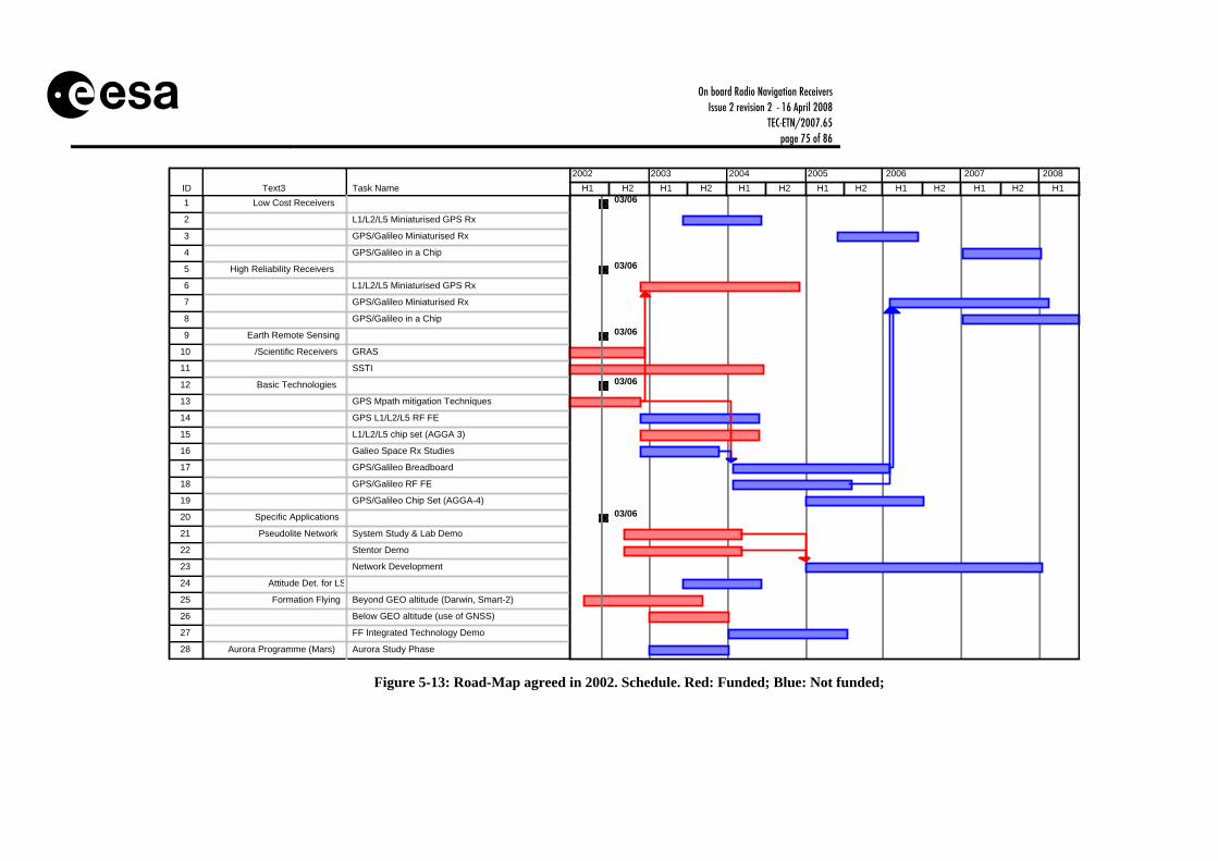
On board Radio Navigation Receivers Issue 2 revision 2 - 16 April 2008
TEC-ETN/2007.65 page 75 of 86
ID Text3 Task Name1 Low Cost Receivers
2 L1/L2/L5 Miniaturised GPS Rx
3 GPS/Galileo Miniaturised Rx
4 GPS/Galileo in a Chip
5 High Reliability Receivers
6 L1/L2/L5 Miniaturised GPS Rx
7 GPS/Galileo Miniaturised Rx
8 GPS/Galileo in a Chip
9 Earth Remote Sensing
10 /Scientific Receivers GRAS
11 SSTI
12 Basic Technologies
13 GPS Mpath mitigation Techniques
14 GPS L1/L2/L5 RF FE
15 L1/L2/L5 chip set (AGGA 3)
16 Galieo Space Rx Studies
17 GPS/Galileo Breadboard
18 GPS/Galileo RF FE
19 GPS/Galileo Chip Set (AGGA-4)
20 Specific Applications
21 Pseudolite Network System Study & Lab Demo
22 Stentor Demo
23 Network Development
24 Attitude Det. for LS
25 Formation Flying Beyond GEO altitude (Darwin, Smart-2)
26 Below GEO altitude (use of GNSS)
27 FF Integrated Technology Demo
28 Aurora Programme (Mars) Aurora Study Phase
03/06
03/06
03/06
03/06
03/06
H1 H2 H1 H2 H1 H2 H1 H2 H1 H2 H1 H2 H12002 2003 2004 2005 2006 2007 2008
Figure 5-13: Road-Map agreed in 2002. Schedule. Red: Funded; Blue: Not funded;
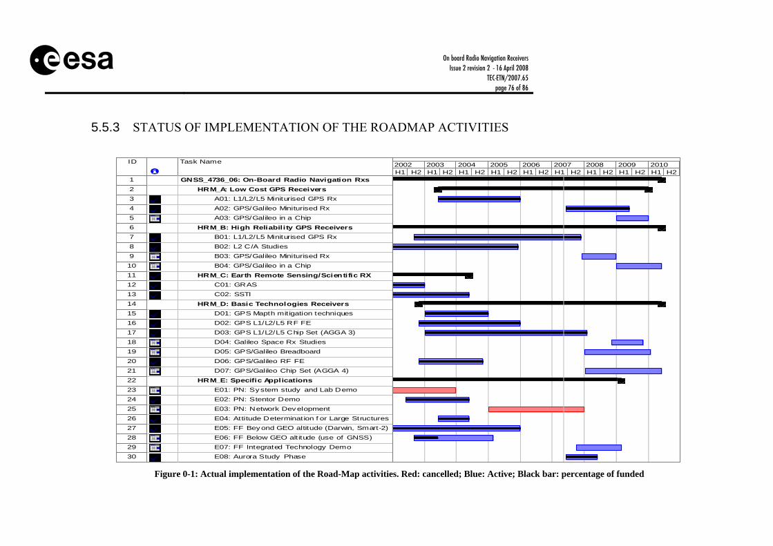
On board Radio Navigation Receivers Issue 2 revision 2 - 16 April 2008
TEC-ETN/2007.65 page 76 of 86
5.5.3 STATUS OF IMPLEMENTATION OF THE ROADMAP ACTIVITIES
ID Task Name
1 GNSS_4736_06: On-Board Radio Navigation Rxs2 HRM_A: Low Cost GPS Receivers3 A01: L1/L2/L5 Miniturised GPS Rx4 A02: GPS/Galileo Miniturised Rx5 A03: GPS/Galileo in a Chip6 HRM_B: High Reliability GPS Receivers7 B01: L1/L2/L5 Miniturised GPS Rx8 B02: L2 C/A Studies9 B03: GPS/Galileo Miniturised Rx10 B04: GPS/Galileo in a Chip11 HRM_C: Earth Remote Sensing/Scientific RX12 C01: GRAS13 C02: SSTI14 HRM_D: Basic Technologies Receivers15 D01: GPS Mapth mitigation techniques16 D02: GPS L1/L2/L5 RF FE17 D03: GPS L1/L2/L5 Chip Set (AGGA 3)18 D04: Galileo Space Rx Studies19 D05: GPS/Galileo Breadboard20 D06: GPS/Galileo RF FE21 D07: GPS/Galileo Chip Set (AGGA 4)22 HRM_E: Specific Applications23 E01: PN: System study and Lab Demo24 E02: PN: Stentor Demo25 E03: PN: Network Development26 E04: Attitude Determination f or Large Structures27 E05: FF Beyond GEO altitude (Darwin, Smart-2)28 E06: FF Below GEO alt itude (use of GNSS)29 E07: FF Integrated Technology Demo30 E08: Aurora Study Phase
H1 H2 H1 H2 H1 H2 H1 H2 H1 H2 H1 H2 H1 H2 H1 H2 H1 H22002 2003 2004 2005 2006 2007 2008 2009 2010
Figure 0-1: Actual implementation of the Road-Map activities. Red: cancelled; Blue: Active; Black bar: percentage of funded
On board Radio Navigation Receivers Issue 2 revision 2 - 16 April 2008
TEC-ETN/2007.65 page 77 of 86
6 CONCLUSIONS Extract from Conclusions of the 2nd Semester 2007 Meetings, ESA/IPC(2008)31, endorsed by IPC at its 243rd meeting on 2-4 April 2008.
6.1 Status The vast majority of LEO satellites planned, built and launched over the last years rely primarily on GNSS receivers for timing and navigation purposes. Other GNSS space navigation applications are navigation in GEO/HEO orbits, tracking of launchers and re-entry vehicles, Formation Flying (FF) and Rendezvous (RdV) missions. While GNSS receiver technology for LEO satellites has generally matured and reached a commercial status, the same does not apply for the latter category of applications. Receivers targeting at these type of missions are still experimental, with the exception of those for ATV. These applications and technologies are expected to have a significant importance during the coming years. In addition to the navigation oriented applications, GNSS sensors are more and more employed as scientific instruments. The accuracy obtained in Precise Orbit Determination (POD) and Radio Occultation (RO) using on-board GNSS has opened a new era in science and earth observation satellite applications. Today, important changes in the satellite navigation field are taking place with the new GNSS signals and systems being developed in the various parts of the world. The new GNSS systems (Galileo, Compass, modernised GPS/GLONASS, SBAS) will offer new and more type of signals, improving the navigation performance and reliability, and making possible the development of innovative signal and data processing techniques. The new signals will also allow the consolidation of navigation concepts like LEO Formation Flying (FF) and virtual platforms. Innovative GNSS technologies will give to Europe an excellent opportunity to become world leader in these areas. At the same time, the ongoing advances of micro-technologies and the integration with other sensors (MEMS), makes possible to conceive new radionavigation space technologies that could open the door to a new era in space exploration and space applications. Europe is currently the world leader for GNSS space receivers. European industry is able to supply several off the shelf GNSS products covering all type of applications. The competitiveness of the European industry in the field has been achieved thanks to the support of technology development through ESA and other European agencies. Furthermore, European technology has benefited from the synergy between commercial and institutional markets GNSS space receiver technology is therefore fundamental for European space, both commercial and scientific applications. GNSS brings significant cost saving and on-board autonomy to the competitiveness of European systems. For scientific applications, GNSS provides possibilities that are not possible without this technology.

On board Radio Navigation Receivers Issue 2 revision 2 - 16 April 2008
TEC-ETN/2007.65 page 78 of 86
Purchase from U.S. of state-of-the-art GPS receivers, as for many other advanced systems for Space and Defense, is often limited by export restrictions. It is therefore essential to ensure the future availability of several European sources. Harmonisation on this technology area was previously conducted in 2002. Of the 24 activities (amounting to 31.15M€) defined in the 2002 Roadmap, 14 have been fully covered (equivalent to 41% budget request) and 1 partially covered (equivalent to 2% budget request), with a total budget obtained of 14.62M€ (47% overall coverage).
6.2 Conclusions The Roadmap (Issue 2, Rev. 2), as updated following the Roadmap Meeting, is supported by THAG. The proposed approach covers the several types of GNSS space receivers: low cost receivers based on COTS, high reliability receivers (SF and MF) and scientific instruments. Two or three different companies are addressing each of these markets and it is considered enough. ESA has focused on the last two markets, in collaboration with national delegation, leaving the low cost receivers for industry or national agencies (although support of ESA is not excluded). The strategy claims for development of innovative GNSS receivers and scientific instruments covering the new GNSS signals, consolidation of the already initiated core technologies (RF and Baseband ASICs), and development of navigations prototypes for supporting space exploration. SW based receivers are covered only at feasibility level. The proposed development approach addresses 8 main areas (aims): Aim A: Low Cost Receivers Aim B: High Reliability MF Receivers Aim C: High Reliability SF Receivers Aim D: Core Technologies Aim E: Earth Observation & Scientific Instruments Aim F: SW Based Receivers Aim G: Exploration Navigation Technologies Aim H: Technology Test Benches
The Roadmap indicates 11.75M€ of new funding request in addition to the already approved 18.86M€ for this technology area. Distribution per priority, per programme and over time (budget distributed over years) is provided below.
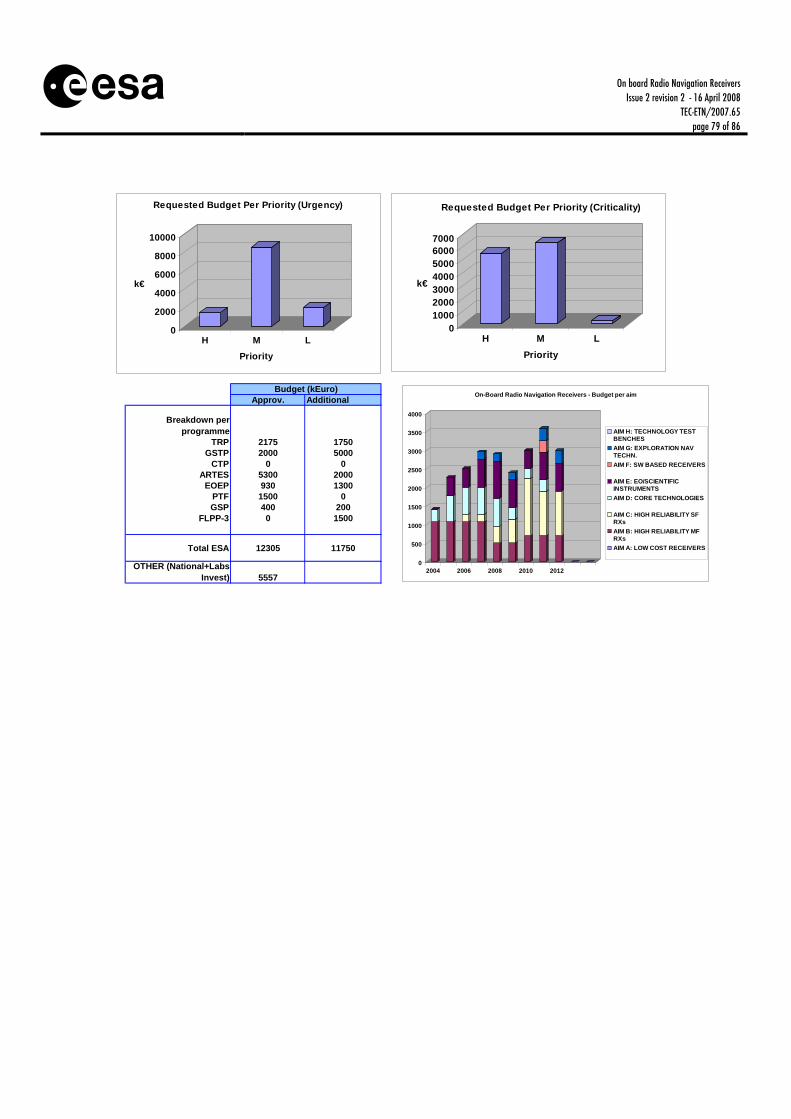
On board Radio Navigation Receivers Issue 2 revision 2 - 16 April 2008
TEC-ETN/2007.65 page 79 of 86
0
2000
4000
6000
8000
10000
k€
H M LPriority
Requested Budget Per Priority (Urgency)
01000200030004000500060007000
k€
H M LPriority
Requested Budget Per Priority (Criticality)
Approv. Additional
Breakdown per programme
TRP 2175 1750GSTP 2000 5000
CTP 0 0ARTES 5300 2000
EOEP 930 1300PTF 1500 0GSP 400 200
FLPP-3 0 1500
Total ESA 12305 11750
OTHER (National+Labs Invest) 5557
Budget (kEuro)
0
500
1000
1500
2000
2500
3000
3500
4000
2004 2006 2008 2010 2012
On-Board Radio Navigation Receivers - Budget per aim
AIM H: TECHNOLOGY TESTBENCHESAIM G: EXPLORATION NAVTECHN.AIM F: SW BASED RECEIVERS
AIM E: EO/SCIENTIFICINSTRUMENTSAIM D: CORE TECHNOLOGIES
AIM C: HIGH RELIABILITY SFRXsAIM B: HIGH RELIABILITY MFRXsAIM A: LOW COST RECEIVERS

On board Radio Navigation Receivers Issue 2 revision 2 - 16 April 2008
TEC-ETN/2007.65 page 80 of 86
APPENDIX A - MARKET ESTIMATE ON BOARD RADIO NAVIGATION RECEIVERS: MARKET ESTIMATE Hypothesis: • All worldwide LEO satellites and all launchers are candidates for being equipped with standard
off the shelf onboard radio navigation receivers. • The radio navigation equipment on board navigation satellites is excluded from the present
category of equipment under harmonisation. • Sounding rockets and sub-orbital flights are excluded from the market estimate because they
would use terrestrial commercial units with little ruggerization and not requiring the expertise of space established companies.
• High orbit satellites and deep space satellites are considered as candidates for embarking few
technology demonstration radio navigation units (within the foreseeable future, see chapter 4 of the technical dossier).
• There will be few scientific payloads measuring radio-navigation signal occultation, reflection
or scattering (see chapter 4 of the technical dossier). • The market for standard off the shelf space radio navigation receivers can be considered global.
However, the satellites counted in the ESA LTP can be considered as captive for the European industry in case that the competition situation would not allow for sales elsewhere.
• The market for technology demonstration units and for science experiments can be considered
protected and the market for European space firms is limited to the possibilities offered by the European missions.
• There are basically two categories of radio-navigation receivers. The ones using rad-hard
components and the ones using radiation protection by circuit design. It is assumed that the choice for using rad-hard components corresponds to missions with expected duration longer than 5 years whereas for lower expected mission duration a cheaper solution would be preferred.
• The different applications of the off the shelf radio navigation receivers (relative navigation,
enhanced precision, attitude determination, use in GEO, …) requires specific development and customisation, but these enhanced applications can be considered as evolution of the basic off the shelf product and there is not need for further market segmentation taken into account the different uses and precision requirements.

On board Radio Navigation Receivers Issue 2 revision 2 - 16 April 2008
TEC-ETN/2007.65 page 81 of 86
• We assume a cost of €100k for units not mounting rad-hard components and a cost of €1m in the other cases.
• The above hypothesis would not change during the reference period indicated in the boundaries Boundaries: The market prospect for LEO satellites and launchers is limited to the period 2007 – 2016, the figures about missions and number of satellites are extracted from the Euroconsult publication “World market survey of satellites to be launched by 2016” Discussion and result: The number of LEO satellites expected to be launched in the period 2007 – 2016 is 480. From these 480, 140 are planned for a life span shorter than 5 years. From the 480, 30 can be identified in the ESA LTP and therefore considered as captive market. The number of orbital launches in this 10 years period can be approximate to 700 from which 100 European. The number of European scientific payloads would probably be lower than 5 (PARIS, METOP B and C and two more not yet defined). We can also suppose that each of the 3 European large Prime contractors involved in GEO activities would perform in this period one technology experiment in GEO. The above situation leads to an annual average potential market accessible to the EU industry of: • 25 low radiation tolerance units (€2,5m ) • 25 high radiation tolerance units (€25m ) • 1 one shoot special science or research unit In case of entry barriers in non-EU markets or in case of poor competitiveness of the EU industry, the European captive market can procure up to 15 units per year

On board Radio Navigation Receivers Issue 2 revision 2 - 16 April 2008
TEC-ETN/2007.65 page 82 of 86
APPENDIX B – GNSS MODERNISATION PLANS
7 GNSS SYSTEMS. STATUS AND MODERNISATIONS
7.1 GPS and GLONASS The GPS system was developed in the sixties by the US Department of Defence (DoD) who still remain responsible for the overall management through the GPS Joint Program Office (JPO). The GPS system comprises three segments, the space, ground and user segment. The space segment consists of 24 satellites orbiting the Earth at approximately 20200 km every 12 hours. The number of active and healthy GPS satellites was 30 in April 2007, and supposed to be 31 and September 2007. The launch schedule and failure rates indicate that more than 32 active and healthy GPS C/A codes could be present as soon as 2008. Moreover The US GPS project office published an announcement warning the GPS receiver manufacturers to take into account the increase of GPS satellites. The GPS satellites today broadcast navigation signals at two frequencies. The L1 carrier is modulated by two Pseudo-Random Noise (PRN) sequences called PRN codes. The L1 C/A code is open and used by the civil community for navigation with an official precision of 24 m, and a measured precision around 10 m. The L2 carrier has just one code, the L2 P-code. The P code is encrypted and only used for military applications, with an official accuracy of 16 m. The P code has better accuracy and resistance to multipath and interference than the C/A code. GPS receivers use the different codes to distinguish between satellites and perform the pseudorange measurements, which are used to fix the position. GPS is then a dual-use system, providing military and civil users with position, navigation and time services. ROSKOSMOS is the controller of the GLONASS system and its developments. There is also an Interagency Coordination Board, which coordinates the GLONASS program with several Russian ministries, including the Ministry of Transport, Defence, Industry and Energy. The space segment consists of 24 satellites in MEO orbit. The satellites today broadcast navigation signals at the same frequencies than GPS (L1, L2), but in FDMA mode, with two different PRN codes in each frequency, one for civil users and one for military use. GLONASS open civil service provides today around 15 meters 3-D accuracy, assuming full constellation and open sky. In fact, the current total number of healthy GLONASS satellites in orbit is 18, due to financial problems during last years to maintain the constellation.
7.2 Galileo The Galileo system is the European initiative to develop a civil global navigation satellite system that provides high accuracy and reliable positioning, navigation and timing services. Galileo will

On board Radio Navigation Receivers Issue 2 revision 2 - 16 April 2008
TEC-ETN/2007.65 page 83 of 86
be compatible and interoperable with GPS and GLONASS, offering multiple frequencies (E1, E5, and E6). The signals are modulated in BPSK and BOC by PRN codes and data, with a total of 10 different signals, with different chip rates, bit rates and code lengths, and covering different types of services (see Table 7-1). The constellation will consist of 30 spacecraft at 23500 km altitude.
Table 7-1: Overview of the Galileo SIS parameters
250---
250
Data (sps)
2.55751.0231.023
Chipr. (Mcps)
PRSG/Nav15.345BOCcosDataL1P1023001.023BOCPilot
Constant envelope
OS,CS, SoL
I/Nav40921.023BOCDataL1F
Multiplex. scheme
Serv.Mess. Type
C. len.(chips)
Subc.(MHz)
Modulat.Chan.Signal
250---
250
Data (sps)
2.55751.0231.023
Chipr. (Mcps)
PRSG/Nav15.345BOCcosDataL1P1023001.023BOCPilot
Constant envelope
OS,CS, SoL
I/Nav40921.023BOCDataL1F
Multiplex. scheme
Serv.Mess. Type
C. len.(chips)
Subc.(MHz)
Modulat.Chan.Signal
250---
1000
5.1155.1155.115
PRSG/Nav10.23BOCcosDataE6P511500---BPSKPilot
Constant envelope
CSC/Nav5115---BPSKDataE6C
250---
1000
5.1155.1155.115
PRSG/Nav10.23BOCcosDataE6P511500---BPSKPilot
Constant envelope
CSC/Nav5115---BPSKDataE6C
---250---50
10.23010.23010.23010.230
1023000---BPSKPilotOS,CS,
SoLI/Nav40920---BPSKDataE5b
1023000---BPSKPilotAltBOCOS,CSF/Nav204600---BPSKDataE5a
---250---50
10.23010.23010.23010.230
1023000---BPSKPilotOS,CS,
SoLI/Nav40920---BPSKDataE5b
1023000---BPSKPilotAltBOCOS,CSF/Nav204600---BPSKDataE5a
E2 E1L1 1.575 GHzE6 1.278 GHz
E5aE5 1.192 GHz
E5b
L1 1.575 GHzL2 1.227 GHzL5 1.176 GHz
OS / SoL / PRSCS / PRSOS / SoL
L5
L1 C/A / P(Y) code / M code / L1CL2 C / P(Y) code / M code
E2 E1L1 1.575 GHzE6 1.278 GHz
E5aE5 1.192 GHz
E5b E2 E1L1 1.575 GHzE6 1.278 GHz
E5aE5 1.192 GHz
E5b
L1 1.575 GHzL2 1.227 GHzL5 1.176 GHz L1 1.575 GHzL2 1.227 GHzL5 1.176 GHz
OS / SoL / PRSCS / PRSOS / SoL
L5
L1 C/A / P(Y) code / M code / L1CL2 C / P(Y) code / M code
Figure 7-1: Galileo Signals. Frequency Bands
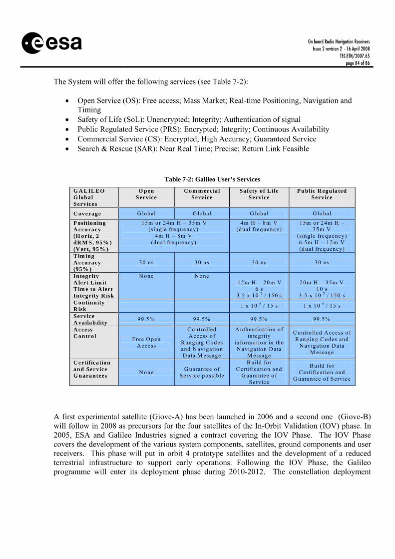
On board Radio Navigation Receivers Issue 2 revision 2 - 16 April 2008
TEC-ETN/2007.65 page 84 of 86
The System will offer the following services (see Table 7-2):
• Open Service (OS): Free access; Mass Market; Real-time Positioning, Navigation and Timing
• Safety of Life (SoL): Unencrypted; Integrity; Authentication of signal • Public Regulated Service (PRS): Encrypted; Integrity; Continuous Availability • Commercial Service (CS): Encrypted; High Accuracy; Guaranteed Service • Search & Rescue (SAR): Near Real Time; Precise; Return Link Feasible
Table 7-2: Galileo User’s Services
G A L IL E O G lobal Services
O pen Serv ice
C o m m ercia l Serv ice
Safety of L ife Serv ice
P ublic R egulated Serv ice
C overage G lobal G lobal G lobal G lobal
P ositioning A ccuracy (H oriz, 2 dR M S, 95% ) (V ert, 95% )
15m or 24m H – 35 m V (single frequency)
4m H – 8m V (dual frequency)
4m H – 8m V (dual frequency)
15m or 24m H – 35m V
(single frequency) 6 .5m H – 12 m V (dual frequency)
T im ing A ccuracy (95% )
30 ns 30 ns 30 ns 30 ns
Integrity
A lert L im it T im e to A lert Integrity R isk
N one N one 12m H – 20 m V
6 s 3 .5 x 10 -7 / 150 s
20m H – 35 m V
10 s 3 .5 x 10 -7 / 150 s
C ontinuity R isk 1 x 10 -5 / 15 s 1 x 10 -5 / 15 s
Service A vailability 99 .5% 99 .5% 99 .5% 99 .5%
A ccess C ontro l Free O pen
A ccess
C ontrolled A ccess o f
R anging C odes and N avigation D ata M essage
A uthentication o f integrity
in form ation in the N avigation D ata
M essage
C ontro lled A ccess o f R anging C odes and
N avigation D ata M essage
C ertification and Serv ice G uarantees N one G uarantee o f
Service possib le
B uild fo r C ertification and
G uarantee o f Service
B uild fo r C ertification and
G uarantee o f Service
A first experimental satellite (Giove-A) has been launched in 2006 and a second one (Giove-B) will follow in 2008 as precursors for the four satellites of the In-Orbit Validation (IOV) phase. In 2005, ESA and Galileo Industries signed a contract covering the IOV Phase. The IOV Phase covers the development of the various system components, satellites, ground components and user receivers. This phase will put in orbit 4 prototype satellites and the development of a reduced terrestrial infrastructure to support early operations. Following the IOV Phase, the Galileo programme will enter its deployment phase during 2010-2012. The constellation deployment

On board Radio Navigation Receivers Issue 2 revision 2 - 16 April 2008
TEC-ETN/2007.65 page 85 of 86
phase will consist of putting all the operational satellites in orbit and in the full deployment of the ground infrastructure.
7.3 GPS and GLONASS modernisations The United States are now implementing a modernisation programme, with new satellites called Block IIR-M and Block IIF, new signals, L2c and L5, and a modernized ground segment. This GPS modernisation programme aims to deliver significant improvements to military and civil users. As part of this GPS Modernisation programme, 8 of the current Block IIR satellites are being upgraded by adding more power and new signals. These satellites are referred to as Block IIR-M. The latest generation of satellites, Block IIF, is under development. The modernised Block IIR-M and IIF satellites will incorporate an additional military signal (M-Code) on L1 and L2 and will add two new dedicated civil signals, L2C (Block IIR-M, IIF) and L5 (Block IIF only). The first Block IIR-M satellite was launched in 2005 and the first Block IIF satellite is planned for 2008. The GPS ground segment is also increasing the number of ground monitoring stations to improve the satellite orbit determination and time synchronization process. The GPS IIR-M and GPS IIF navigation messages will manage up to 36 GPS satellites. No more than 36 GPS satellites could be addressed, since there is only 36 legacy GPS C/A codes including the spare codes described in the GPS ICD. The Block IIR and Block IIF satellites will also integrate a new function called AUTONAV. This function will provide both improved accuracy and long term validity of the navigation data message for up to several months without uplinks from the ground. This is obtained using inter-satellite range measurements.
1227 MHz 1575 MHz1176 MHz
L2 L1L5
P(Y)P(Y)C/AC/A
P(Y)P(Y)
P(Y)P(Y)
C/AC/A
P(Y)P(Y)
CSCSMM MM
Present Signals
Signals AfterModernization
1227 MHz 1575 MHz1176 MHz
L2 L1L5
P(Y)P(Y)C/AC/A
P(Y)P(Y)
P(Y)P(Y)
C/AC/A
P(Y)P(Y)
CSCSMM MM
Present Signals
Signals AfterModernization
Figure 7-2: GPS Modernised Signals. Frequency Bands

On board Radio Navigation Receivers Issue 2 revision 2 - 16 April 2008
TEC-ETN/2007.65 page 86 of 86
In long term, GPS will implement a new modernisation programme called GPS III. The GPS III system will consist of 30 satellites. The GPS III satellites will incorporate additional civil (L1C) and military signals, reprogrammable payload and flexible power, on-board signal integrity monitoring, cross-links to support communications and possibly inter-satellite ranging. The first GPS III launch is planned for 2013 and with full operations starting in 2020.
Milestones
Space Segment
Control Segment
201720161999 2000 2001 2002 2003 2004 2005 2006 2007 2008 2009 2010 2011 2012 2013 2014 2015 2016
IIF SV1Launch
IIF Lite Deliveries IIF SV7-SV12IIF SV1-SV6
IIF SV1-SV6IIF Lite Launches
IIF SV7-SV12
IIF OCSM-Code/L5
OCS
OCSTraining/Validation
ATP
GPS-IIIFull Capability
IOC
GPS-IIIFull Capability
FOC
DeliverS/W
OT&EComp.
SPI ContractDefinitization
M-CodeEarth
(18SV)
M-CodeEarth
(24 SV)
CY
L5IOC
L5FOC
GPS III DeliveriesSV1-SV3
SV1-SV3GPS III Launches
SV4 - SVNN
SV4 - SVNN
IIR Mod Deliveries IIR SV10-SV21
IIR Mod Launches IIR SV10-SV21
IIR ModFirst
Launch
2018 2019 2020
Milestones
Space Segment
Control Segment
201720161999 2000 2001 2002 2003 2004 2005 2006 2007 2008 2009 2010 2011 2012 2013 2014 2015 201620161999 2000 2001 2002 2003 2004 2005 2006 2007 2008 2009 2010 2011 2012 2013 2014 2015 2016
IIF SV1Launch
IIF Lite Deliveries IIF SV7-SV12IIF SV1-SV6
IIF SV1-SV6IIF Lite Launches
IIF SV7-SV12
IIF OCSM-Code/L5
OCS
OCSTraining/Validation
ATP
GPS-IIIFull Capability
IOC
GPS-IIIFull Capability
FOC
DeliverS/W
OT&EComp.
SPI ContractDefinitizationSPI ContractDefinitization
M-CodeEarth
(18SV)
M-CodeEarth
(24 SV)
CY
L5IOC
L5FOC
GPS III DeliveriesSV1-SV3
SV1-SV3GPS III Launches
SV4 - SVNN
SV4 - SVNN
IIR Mod Deliveries IIR SV10-SV21
IIR Mod Launches IIR SV10-SV21
IIR ModFirst
Launch
2018 2019 2020
Figure 7-3: GPS Modernisation Plan
The Russian Aerospace Agency has the approval of the Russian government to continue a plan until 2011, to deploy a complete GLONASS constellation of 24 satellites. Russia proposes to have 18 operational satellites by the end of 2008 and 24 operational satellites by the end of 2010. The GLONASS-K satellite will be developed as part of a GLONASS modernisation plan (Figure 7-4). The GLONASS-K satellites will be launched over the period 2008-2015 and operational until around 2025. The system goals are similar to GPS III. These new satellites will incorporate a third frequency named L3, in the L-band (close to E5b), to improve reliability and accuracy; will have the satellite lifetime increased to 10 years; the satellite mass will be reduced by half; additional payloads are planned, including Search and Rescue payload; will include Integrity transmissions. There is also a Russian programme for the development of next generation GLONASS satellites, which are referred to as GLONASS-KM. The first launch of a GLONASS-KM satellite is expected in 2015.

On board Radio Navigation Receivers Issue 2 revision 2 - 16 April 2008
TEC-ETN/2007.65 page 87 of 86
Figure 7-4: GLONASS Modernisation Plan