mysinger capstone_final program_03 technical
DESCRIPTION
Nicole Mysinger Interior Design Capstone project for DAAP Works 2012. Project is an indoor soccer training facility in West Chester, Ohio. Book 3 of 4: TechnicalTRANSCRIPT

3
JUST FOR
KICKSTechnical / Concept & Process


Technical / Concept & Process
JUST FOR
KICKS

2
Table of Contents
Esquese Exercise 4
Inspiration Images 8
Plan Beautiful 12
Schematic Review 16
Plan Progression 22
Midterm Review 26
Progress Work 34
Winter Final Design 40
Appendix 46

3

4
Esquese Exercise

5

6
Esquese Exercise
Second Floor Plan
First Floor Plan

7
Just For Kicks is a state of the art indoor soccer facility that is located in West Chester, Ohio right off of Interstate 75. Located in a great location with a variety of food and shopping nearby, this facility is easy to reach and in the heart of a family area in one of Cincinnati’s best suburbs. The facility will provide people of all ages with a space to enjoy the atmosphere of soccer that is so dearly loved around the world. Teams from all over the Cincinnati area and the tri-state will flock here to get a piece of the action. Using motifs derived from all things soccer the building has a unique personality that will keep you excited and energized from the moment you hit the parking lot. Just for Kicks is the place to be for all soccer enthusiasts.
Parti
First Floor Plan
Section

8
Inspiration Images

9

10
Inspiration Images

11

12
Plan Beautiful

13

14
Plan Beautiful

15

16
Schematic Review

17
18
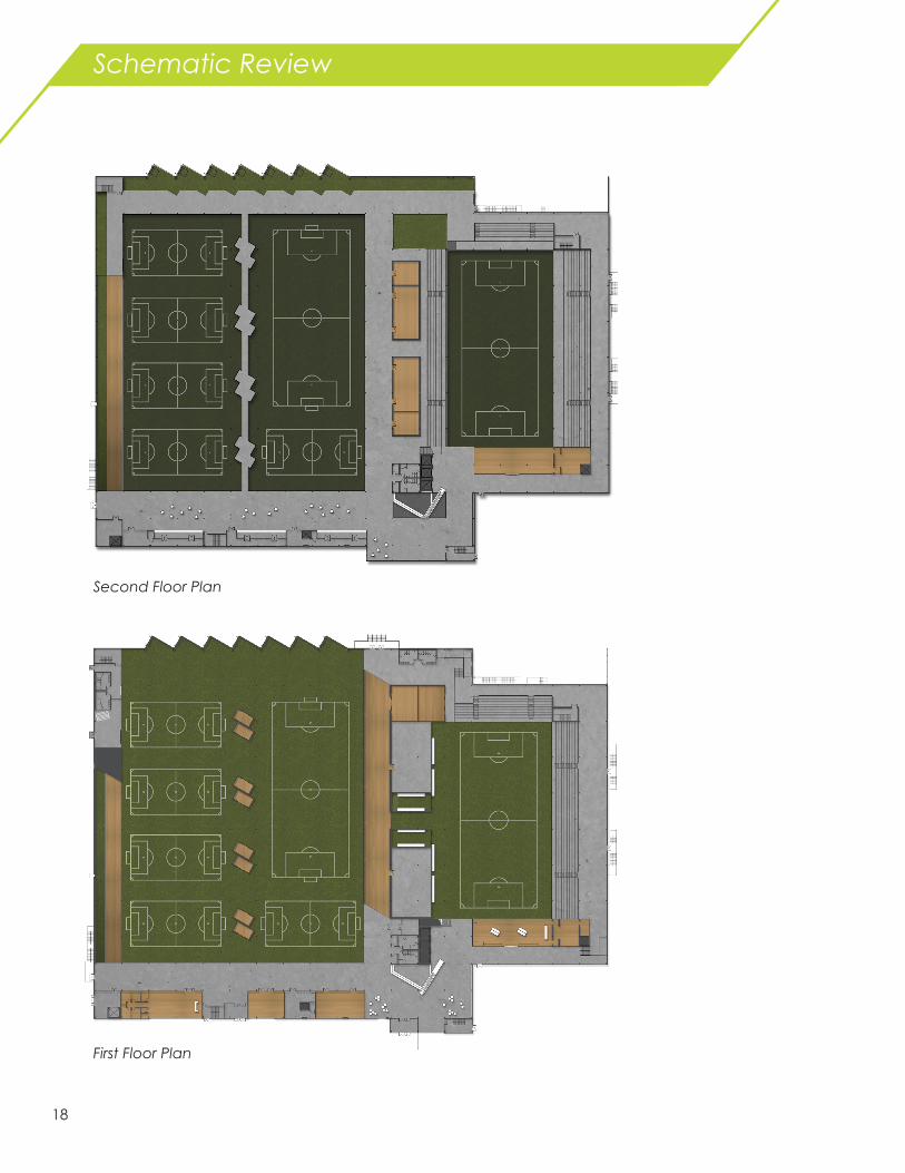
Schematic Review
Second Floor Plan
First Floor Plan

19
Spatial Breakdowns
Ideation Sketches

20
Entrance View
Players Tunnel

21
Training Fields
Training Ramp and Training Fields

22
Plan Progression

23

24
Plan Progression

25

26
Winter Midterm

27

28
Winter Midterm
Second Floor Plan
First Floor Plan
Championship Field
Front Desk/ Lobby
Spectator Seating
Physical Therapy
Men’s Locker
Women’s Locker
The Tunnel
Workout AWorkout B
Storage
Ramp
Shooting Cages Drop off Zone/Back Lobby
Spectator Seating
Cafe Area
Office
Office
Training Below

29
Axonometric
Sections

30
Entry
Players Tunnel

31
Tunnel Ideation
Sections

32
Entry
Players Tunnel

33
Tunnel Ideation
Sections

34
Process Work

35

36
Process Work

37

38

39

40
Winter Final Design

41
42
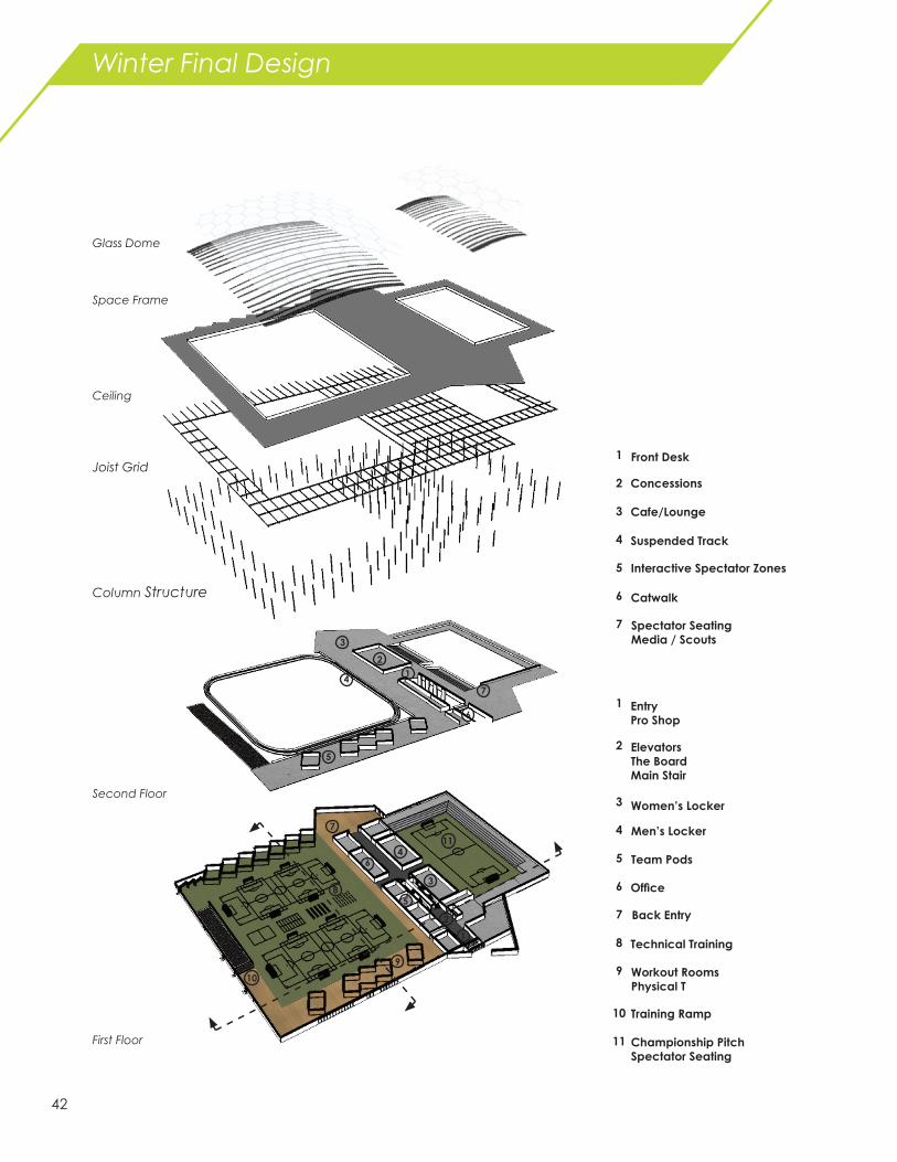
Winter Final Design
First Floor
ElevatorsThe BoardMain Stair
Technical Training
Championship PitchSpectator Seating
Workout RoomsPhysical Therapy
Team Pods
Men’s Locker
Women’s Locker
Training Ramp
Office
Second Floor
Column Structure
Joist Grid
Ceiling
Space Frame
Glass Dome
1
2
3
4
5
6
7
8
9
10
11
1
2
3
4
5
6
7
8
9
10
11
EntryPro Shop
Back Entry
Concessions
Interactive Spectator Zones
Suspended Track
Cafe/Lounge
Spectator SeatingMedia / Scouts
1
2
3
4
5
6
7
Front Desk
Catwalk
2
3
4
5
6
7
1

43
Building Facade from Parking lot
Building Facade from Interstate
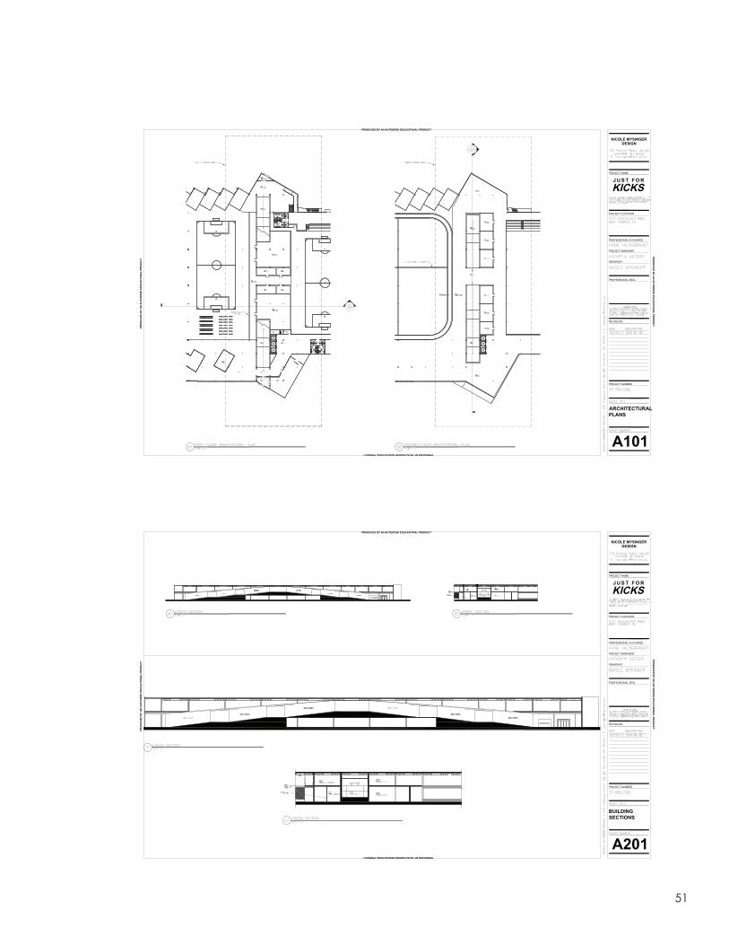
Section
Section
Open Grid Passing and 1v1 Agility Ladder Corever Training

44
Above Threshold Lighting
Art Installation Lighting
Logo/Graphic Wall with Signage
Main Information Desk
Interactive Video Wall
Players Tunnel with Seating above

45
Suspended Track Space Frame with Hexagon Paned Glass
Stadium Seating

46
Appendix

47
48
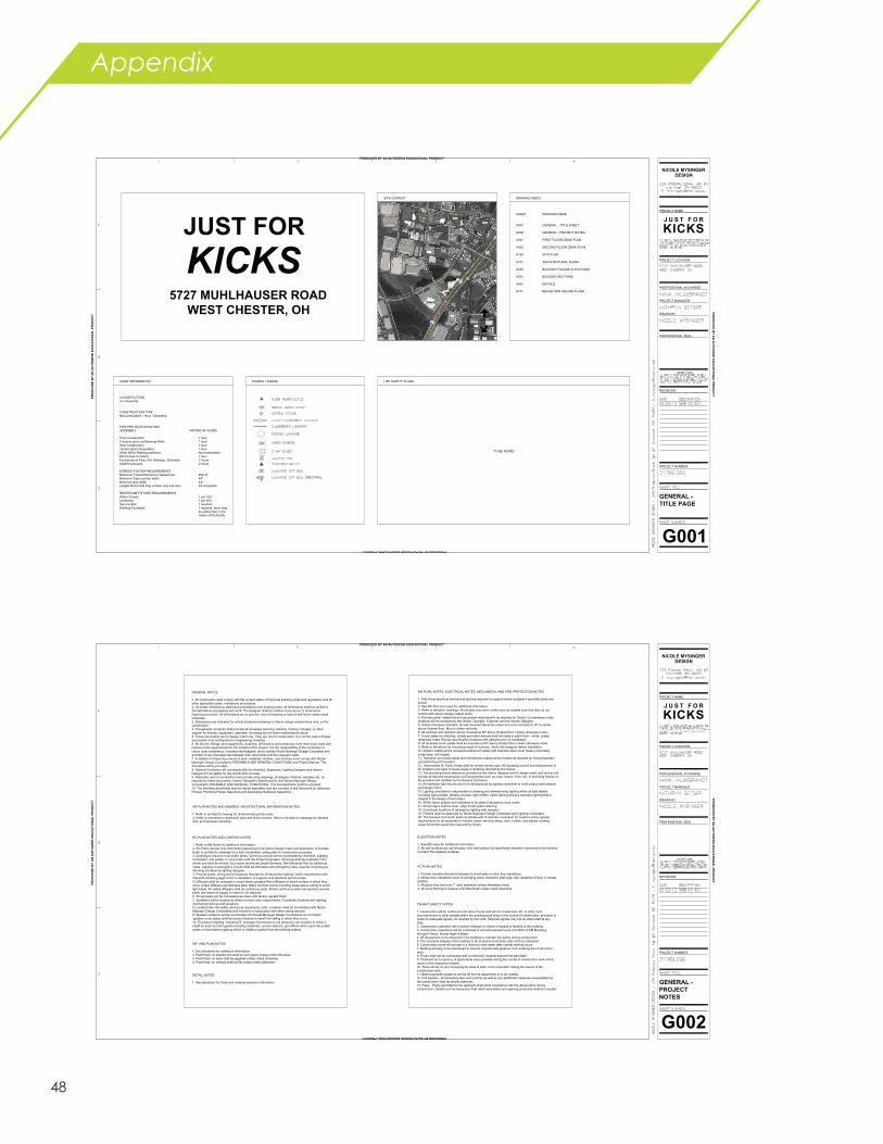
Appendix
JUST FORKICKS
5727 MUHLHAUSER ROADWEST CHESTER, OH
LIFE SAFETY PLANSSYMBOL LEGEND
DRAWING INDEX
SHEET DRAWING NAME
G001 GENERAL - TITLE SHEET
G002 GENERAL - PROJECT NOTES
A001 FIRST FLOOR DEMO PLAN
A002 SECOND FLOOR DEMO PLAN
A100 SITE PLAN
A101 ARCHITECTURAL PLANS
A200 BUILDING FACADE ELEVATIONS
A201 BUILDING SECTIONS
A601 DETAILS
E101 REFLECTED CEILING PLANS
CODE INFORMATION
CLASSIFICATIONA-4 Assembly
CONSTRUCTION TYPENoncombustible 1 Hour / Sprinkled
FIRE PROTECTION RATINGASSEMBLY RATING IN HOURS
Floor Construction 1 hourColumns and Load Bearing Walls 1 hourRoof Construction 1 hourTenant Space Separation 1 hourOther NOnn-Bearing partitions NoncombustibleExit Access Corridors 1 hourEnclosures of Exits, Exit Hallways, Stairwells 2 hoursShaft Enclosures 2 hours
EGRESS SYSTEM REQUIREMENTSMaximum Travel Distance to nearest exit 250'-0"Minimum Clear corridor width 44"Minimum stair width 44"Largest Room that may contain only one door 49 occupants
RESTROOM FIXTURE REQUIREMENTSWater Closets 1 per 150Lavatories 1 per 200Service Sink 1 requiredDrinking Fountains 1 required, more may
be added due to thenature of the facility
SITE CONTEXT
TRUE NORTH
SITE NORTH
TO BE ADDED
DS
NICOLE MYSINGERDESIGN
J U S T F O R
KICKSPROJECT NAME
PROJECT LOCATION
PROFESSIONAL IN CHARGE
PROJECT MANAGER
DRAWN BY
REVISIONS
PROJECT NUMBER
PROFESSIONAL SEAL
G001
GENERAL -TITLE PAGE
PRODUCED BY AN AUTODESK EDUCATIONAL PRODUCT
PRO
DU
CED
BY
AN
AU
TOD
ESK
ED
UC
ATI
ON
AL
PRO
DU
CT
PRODUCED BY AN AUTODESK EDUCATIONAL PRODUCT
PRO
DU
CED
BY A
N A
UTO
DESK
EDU
CA
TION
AL PR
OD
UC
T
GENERAL NOTES
1. All construction shall comply with the current edition of the local building codes and regulations and allother applicable codes, ordinances and statues.2. All written dimensions shall have precedence over drawing scale. all dimensions shall be verified inthe field before proceeding with work. The designer shall be notified of any errors or dimensionsrequiring correction. All dimensions are to grid line, face of masonry or face of wall finish unless notedotherwise.3. Dimensions are indicated for critical locations pertaining to interior design related items only, not forconstruction.4. The general contractor shall provide all necessary blocking, backing, framing, hangers, or othersupport for fixtures, equipment, cabinetry, furnishing and all items requireing the same.5. These documents are for design intent only. They are not for construction. It is not the intent of thesedocuments to be architectural or engineering drawings.6. All fixtures, fittings, and equipments, locations, dimensions and tolerances must meet local, state andnational code requirements for the location of the project. It is the responsibility of the Contractor toinsure code compliance, including handicapped, and to advise Nicole Mysinger Design Consultant andarchitect of any discrepancies between their documents and the required codes.7. In addition to these documents of work, materials, finishes, and furniture must comply with NicoleMysinger Design Consultant's PREAMBLE AND GENERAL CONDITIONS and Project Manual. Thisdocument will be provided.8. General Contractor will coordinate with the Architect, Engineers, Lighting Designer and InteriorDesigner for all details for the construction process.9. Fabricator and./or Contractor must provide shop drawings, prototypes, finishes, samples, etc. asrequired by these documents; Interior Designer's Specifications; and Nicole Mysinger DesignConsultant's PREAMBLE AND GENERAL CONDITIONS. This documentation shall be provided.10. The following documents may be issued seperately and are included in this document by reference:Primary Plumbing Fixture Selections and Decorative Hardware Selections.
AR PLAN NOTES AND GENERAL ARCHITECTURAL INFORMATION NOTES
1. Refer to architect's drawing for dimensioned partition plan.2. Refer to elevations to determine style and finish of doors. Refer to Architect's drawings for detaileddoor and hardware schedule.
RC PLAN NOTES AND LIGHTING NOTES
1. Refer to EM Notes for additional information.2. RC Plans include only information pertaining to the interior design intent and application of finishes.Refer to architect's drawings for a fully coordinated ceiling plan for construction purposes.3. Dimming is required in all public areas. Dimming curcuits will be coordinated by Architect, LightingConsultant, and perator in conjunction with the Project Engineers. Dimming shall be automatic CPUdriven and shall be remote, four scene (minimum) preset dimmers. See Electrical Plan for additionalnotes. Lighting on emergency circuits shall be dimmable with emergency relay override. Dimming perdimming schedule by lighting designer.4. Provide power, wiring and all supports required for all decorative lighting. Verify requirements withOwner/Purchasing Agent prior to installation of supports and electrical service boxes.5. Diffusers shall be conceals in coves where possible.Paint diffusers to match surface in which theyoccur unless diffusers are stainless steel. Black out boot and surrounding areas above ceiling to avoidlight bleed. All visible diffusers shall be continuous slots. Where continuous slots are required, provideblank slot where air supply or return is not required.6. All sprinklers will be concealed pop down with factory applied finish.7. Sprinklers will be located by others to meet code requirements. Coordinate locations with lighting,mechanical devices and speakers.8. Located other life-safety devices as required by code. Locations shall be coordinated with NicoleMysinger Design Consultants and Architect in conjunction with other ceiling devices.9. Speaker locations will be coordinated with Nicole Mysinger Design Consultants and Architect.speaker cover plates shall be factory finished to match the ceiling in which they occur.10. Fluorescent lighting, including PL (compact fluorescent) is not allowed in any location in which itmight be seen by hotel guests including vestibules, service stations, and offices which open into publicareas or have exterior glazing which is visible to guests from the building exterior.
EM PLAN, NOTES, ELECTRICAL NOTES, MECHANICAL AND FIRE PROTECTION NOTES
1. Only those electrical.mechanical devices required to support interior designer's specified items areshown.2. See RC Plan and notes for additional information.3. Refer to elevation drawings, All devices mounted in walls must be located such that they do notconflict with interior design related items.4. Provide power, telephone and equipment requirements as required by Owner, Convenience outletlocations will be reviewed by the Owner, Operator, Engineer and the Interior Designer.5. Unless otherwise indicated, all wall mounted electrical outlets are to be mounted at 18" to centerabove finished floor. Mount outlets vertically.6. All switches and dimmers will be mounted at 48" above finished floor. Unless otherwise noted.7. Cover plates for switches, outlets and other devices shall be metal in paint finish - white, unlessotherwise noted. Review specification locations with designer prior to installation.8. All recessed clock outlets shall be mounted at 60" above finished floor unless otherwise noted.9. Refer to elevations for mounting height of sconces. Verify with designer before installation.10. All floor outlets will be recessed waterproof outlets with stainless steel cover plates (removablescrew type, not hinged).11. Television and audio/visual and microphone outlets will be located as required by Owner/Operatorand Adio/Visual Consultant.12. Thermostats for Public Areas shall be remote sensor type. All operating control and mechanisms tobe located in the back of house areas in locations directed by the Owner.13. The plumbing fixture selections provided by the interior designer are for design intent only and do notinclude all required accessories and components such as traps, drains, trims, etc. Al plumbing fixtures tobe provided and installed by the General Contractor.14. All hardware light fixtures are to be dimensioned by lighting consultant to verify proper performanceand design intent.15. Lighting consultant is responsible for drawing and dimensioning lighting within all light details,including light pockets, drapery pockets, light coffers, cable lighting and any specially lighting that isintegral in the design of the project.16. All fire alarm strobes and indicators to be white if allowed by local codes.17. All exit signs shall be clear, edge lit with green lettering.18. Coordinate locations of emergency lighting with designer.19. Fixtures shall be approved by Nicole Mysinger Design Consultant and Lighting Consultant.20. The General Contractor shall coordinate with th ekitchen consultant for location and/or specialrequirements for all equipment in kitchen areas, services areas, bars, buffets, and display cookingareas.All kitchen equipment required by others.
ELEVATION NOTES
1. See EM notes for additional information.2. All wall surfaces are not elevated. Any wall surface not specifically elevated is assumed to be finishedto match the adjacent surfaces.
FC PLAN NOTES
1. Provide transition/threshold between turf and aisle or other floor transitions.2. Where floor transitions occur at swinging doors, transition shall align with centerline of door in closedposition.3. All grout lines are to be 1" wide maximum unless otherwise noted.4. All wood flooring to receive a full filled finish unless noted otherwise.
WF AND PLAN NOTES
1. See elevations for additional information.2. Paint finish on painted trim shall be semi-gloss unless noted otherwise.3. Paint finish on walls shall be eggshell unless noted otherwise.4. Paint finish on ceilings shall be flat unless noted otherwise.
DETAIL NOTES
1. See elevations for finish and material selection information.
TENANT SAFETY NOTES
1. Construction will be confined to the area of work and will not create dust, dirt, or other suchinconveniences to other tenants within the building at all times in the course of construction provision ismade for adequate egress, as required by the code. Required egress may not be obstructed at anytime.2. Construction operation will not block hallways or means of egress to tenants of this building.3. Construction operations will be confirmed to normal business hours of 8 AM to 5 PM Mondaysthrough Fridays, except legal holidays.4. All precautions to be observed in the building to maintain fire safety during construction.5. The structural integrity of the building to be protected at all times and not to be disturbed.6. Construction noise will be kept to a minimum and cease after normal working hours.7. Building security to be maintained to prevent unauthorized persons, from entering the constructionarea.8. Floors shall not be overloaded with construction material beyond that permitted.9. There will be occupancy of apartments when possible during the course of construction work at theoption of the respective tenants.10. There will be no one occupying the area of work, to be renovated, during the course of theconstruction work.11. Before sprinkler system is turned off the fire department is to be notified.12. Fire System - all necessary laws and controls as well as any additional measures necessitated bythe construction shall be strictly observed.13. Plans - Plans submitted by the applicant shall show compliance with the above items duringconstruction. Details such as temporary fired rated assemblies and opening protective shall be included.
NICOLE MYSINGERDESIGN
J U S T F O R
KICKSPROJECT NAME
PROJECT LOCATION
PROFESSIONAL IN CHARGE
PROJECT MANAGER
DRAWN BY
REVISIONS
PROJECT NUMBER
PROFESSIONAL SEAL
G002
GENERAL -PROJECTNOTES
PRODUCED BY AN AUTODESK EDUCATIONAL PRODUCT
PRO
DU
CED
BY
AN
AU
TOD
ESK
ED
UC
ATI
ON
AL
PRO
DU
CT
PRODUCED BY AN AUTODESK EDUCATIONAL PRODUCT
PRO
DU
CED
BY A
N A
UTO
DESK
EDU
CA
TION
AL PR
OD
UC
T

49
PROJECT NAME
PROJECT LOCATION
PROFESSIONAL IN CHARGE
PROJECT MANAGER
DRAWN BY
REVISIONS
PROJECT NUMBER
PROFESSIONAL SEAL
NICOLE MYSINGERDESIGN
A001
FIRST FLOORDEMO PLAN
PRODUCED BY AN AUTODESK EDUCATIONAL PRODUCT
PRO
DU
CED
BY
AN
AU
TOD
ESK
ED
UC
ATI
ON
AL
PRO
DU
CT
PRODUCED BY AN AUTODESK EDUCATIONAL PRODUCT
PRO
DU
CED
BY A
N A
UTO
DESK
EDU
CA
TION
AL PR
OD
UC
T
PROJECT NAME
PROJECT LOCATION
PROFESSIONAL IN CHARGE
PROJECT MANAGER
DRAWN BY
REVISIONS
PROJECT NUMBER
PROFESSIONAL SEAL
NICOLE MYSINGERDESIGN
A002
SECONDFLOOR DEMOPLAN
PRODUCED BY AN AUTODESK EDUCATIONAL PRODUCT
PRO
DU
CED
BY
AN
AU
TOD
ESK
ED
UC
ATI
ON
AL
PRO
DU
CT
PRODUCED BY AN AUTODESK EDUCATIONAL PRODUCT
PRO
DU
CED
BY A
N A
UTO
DESK
EDU
CA
TION
AL PR
OD
UC
T

50
NICOLE MYSINGERDESIGN
J U S T F O R
KICKSPROJECT NAME
PROJECT LOCATION
PROFESSIONAL IN CHARGE
PROJECT MANAGER
DRAWN BY
REVISIONS
PROJECT NUMBER
PROFESSIONAL SEAL
A002
BUILDINGFACADEOPTIONS
PRODUCED BY AN AUTODESK EDUCATIONAL PRODUCT
PRO
DU
CED
BY
AN
AU
TOD
ESK
ED
UC
ATI
ON
AL
PRO
DU
CT
PRODUCED BY AN AUTODESK EDUCATIONAL PRODUCT
PRO
DU
CED
BY A
N A
UTO
DESK
EDU
CA
TION
AL PR
OD
UC
TNICOLE MYSINGER
DESIGN
PROJECT NAME
PROJECT LOCATION
PROFESSIONAL IN CHARGE
PROJECT MANAGER
DRAWN BY
REVISIONS
PROJECT NUMBER
PROFESSIONAL SEAL
A100
SITEPROPOSALPLAN
PRODUCED BY AN AUTODESK EDUCATIONAL PRODUCT
PRO
DU
CED
BY
AN
AU
TOD
ESK
ED
UC
ATI
ON
AL
PRO
DU
CT
PRODUCED BY AN AUTODESK EDUCATIONAL PRODUCT
PRO
DU
CED
BY A
N A
UTO
DESK
EDU
CA
TION
AL PR
OD
UC
T
51
PROJECT NAME
PROJECT LOCATION
PROFESSIONAL IN CHARGE
PROJECT MANAGER
DRAWN BY
REVISIONS
PROJECT NUMBER
PROFESSIONAL SEAL
NICOLE MYSINGERDESIGN
A101
ARCHITECTURALPLANS
PRODUCED BY AN AUTODESK EDUCATIONAL PRODUCT
PRO
DU
CED
BY
AN
AU
TOD
ESK
ED
UC
ATI
ON
AL
PRO
DU
CT
PRODUCED BY AN AUTODESK EDUCATIONAL PRODUCT
PRO
DU
CED
BY A
N A
UTO
DESK
EDU
CA
TION
AL PR
OD
UC
T
PROJECT NAME
PROJECT LOCATION
PROFESSIONAL IN CHARGE
PROJECT MANAGER
DRAWN BY
REVISIONS
PROJECT NUMBER
PROFESSIONAL SEAL
NICOLE MYSINGERDESIGN
A201
BUILDINGSECTIONS
PRODUCED BY AN AUTODESK EDUCATIONAL PRODUCT
PRO
DU
CED
BY
AN
AU
TOD
ESK
ED
UC
ATI
ON
AL
PRO
DU
CT
PRODUCED BY AN AUTODESK EDUCATIONAL PRODUCT
PRO
DU
CED
BY A
N A
UTO
DESK
EDU
CA
TION
AL PR
OD
UC
T

52
NICOLE MYSINGERDESIGN
PROJECT NAME
PROJECT LOCATION
PROFESSIONAL IN CHARGE
PROJECT MANAGER
DRAWN BY
REVISIONS
PROJECT NUMBER
PROFESSIONAL SEAL
A601
DETAILS
PRODUCED BY AN AUTODESK EDUCATIONAL PRODUCT
PRO
DU
CED
BY
AN
AU
TOD
ESK
ED
UC
ATI
ON
AL
PRO
DU
CT
PRODUCED BY AN AUTODESK EDUCATIONAL PRODUCT
PRO
DU
CED
BY A
N A
UTO
DESK
EDU
CA
TION
AL PR
OD
UC
T
PROJECT NAME
PROJECT LOCATION
PROFESSIONAL IN CHARGE
PROJECT MANAGER
DRAWN BY
REVISIONS
PROJECT NUMBER
PROFESSIONAL SEAL
NICOLE MYSINGERDESIGN
E101
REFLECTEDCEILING PLANS
PRODUCED BY AN AUTODESK EDUCATIONAL PRODUCT
PRO
DU
CED
BY
AN
AU
TOD
ESK
ED
UC
ATI
ON
AL
PRO
DU
CT
PRODUCED BY AN AUTODESK EDUCATIONAL PRODUCT
PRO
DU
CED
BY A
N A
UTO
DESK
EDU
CA
TION
AL PR
OD
UC
T

53

54
Arsene Wenger
Birthdate: October 22, 1949Origin: Strasbourg, France
Position: Manager (Arsenal)Clubs: Mulhouse, ASPV Strasbourg, RC Strasbourg
Arsene Wenger is the longest serving and most successful manager of English Premier League’s Arsenal. Le Professeur, as named by some of his players, is the only manager in the league to go an entire season with a loss, 49 straight wins.
On the Cover...


“You build a player like you build a house. You start with the Foundations, the Fundementals.”
- Arsene Wenger
Nicole MysingerInterior Design [email protected]