myrrha primary heat exchanger design status · pdf filemyrrha primary heat exchanger design...
TRANSCRIPT

MYRRHAPrimary Heat Exchanger design status
Diego CastellitiSCK•CEN
IAEA, Vienna, 21-22 December 2011Copyright © 2011 SCK•CEN

2
Introduction
� MYRRHA project:� Targets� Characteristics� Design status
� MYRRHA Primary Heat Exchanger design� Current layout� T/H parameters� Design choices� Control strategy

3
MYRRHA project [1/5]
� MYRRHA: Multi-purpose hYbrid Research Reactor for High-tech Applications
� MYRRHA facility main targets� Flexible irradiation facility� Minor Actinides (MAs) transmutation aiming at "closed cycle“
(Generation IV requirement)� Accelerator-driven system (ADS) demonstrator� Lead Fast Reactor demonstrator� (Pre-) Gen IV plant

4
MYRRHA project [2/5]
� MYRRHA facility main characteristics� ADS reactor operating in sub-critical mode with ability to operate in
critical mode as well� Fast neutron flux� No electrical power generation� Material testing and isotope production facility � flux performance
maximized in the In-Pile Sections (IPS)� Primary coolant: Lead-Bismuth Eutectic (LBE)� Pool-type reactor� 4 Primary Heat Exchangers (PHXs)� 2 Primary Pumps (PPs)� Secondary coolant: 2-phase water� Tertiary coolant (heat sink): air
5
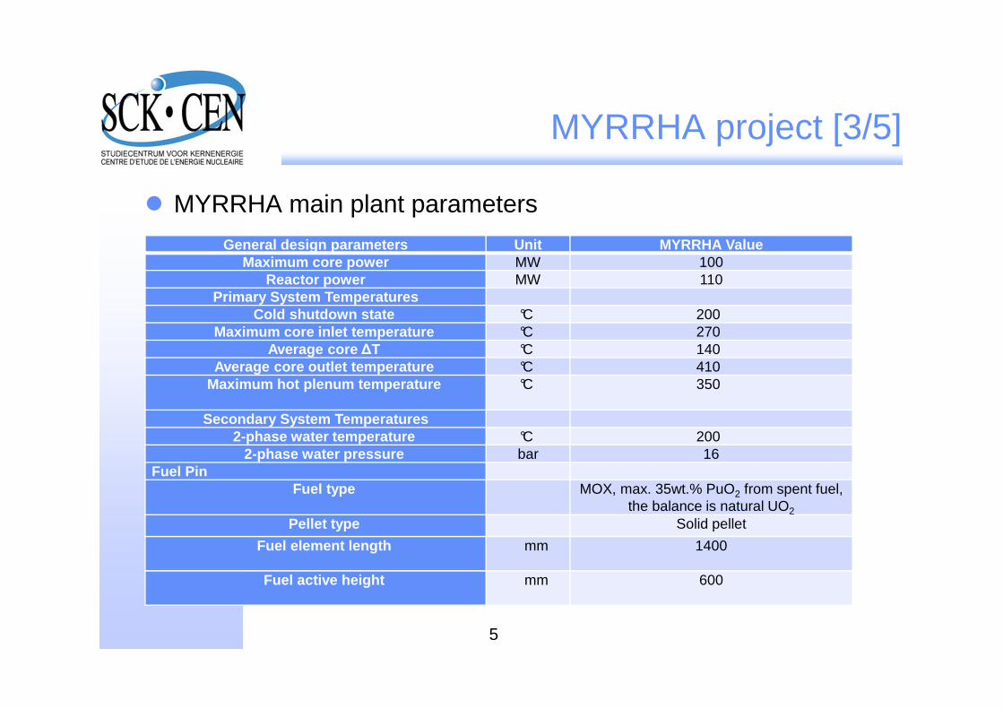
MYRRHA project [3/5]
� MYRRHA main plant parameters
General design parameters Unit MYRRHA ValueMaximum core power MW 100
Reactor power MW 110Primary System Temperatures
Cold shutdown state °C 200Maximum core inlet temperature °C 270
Average core ∆T °C 140Average core outlet temperature °C 410
Maximum hot plenum temperature °C 350
Secondary System Temperatures2-phase water temperature °C 200
2-phase water pressure bar 16Fuel Pin
Fuel type MOX, max. 35wt.% PuO2 from spent fuel, the balance is natural UO2
Pellet type Solid pellet
Fuel element length mm 1400
Fuel active height mm 600

6
MYRRHA project [4/5]
� MYRRHA main plant parameters (continued)
Fuel assembly
Assembly type Hexagonal fuel bundle with wrapper
Number of pins - 127
Spacer type Wire spacer
Assembly length mm 2000
Maximum LBE bulk velocity m/s 2
Core
Number of positions 151
Core diameter mm 1450
Maximum core pressure drop bar 2.5
Reactor vessel
Internal diameter mm ~7600
Length mm ~11000

7
MYRRHA project [5/5]
� Overview of the MYRRHA reactor primary system

8
MYRRHA current PHX layout [1/2]
Shell and tubes counter-current PHX (water flowing in tubes)
Lower HX zone (Water tubes, tube plates and lower plenum)
HX shroud and feed-water tube double-walled against SG rupture accident
Upper HX zone (Feed-water inlet and 2φoutlet)
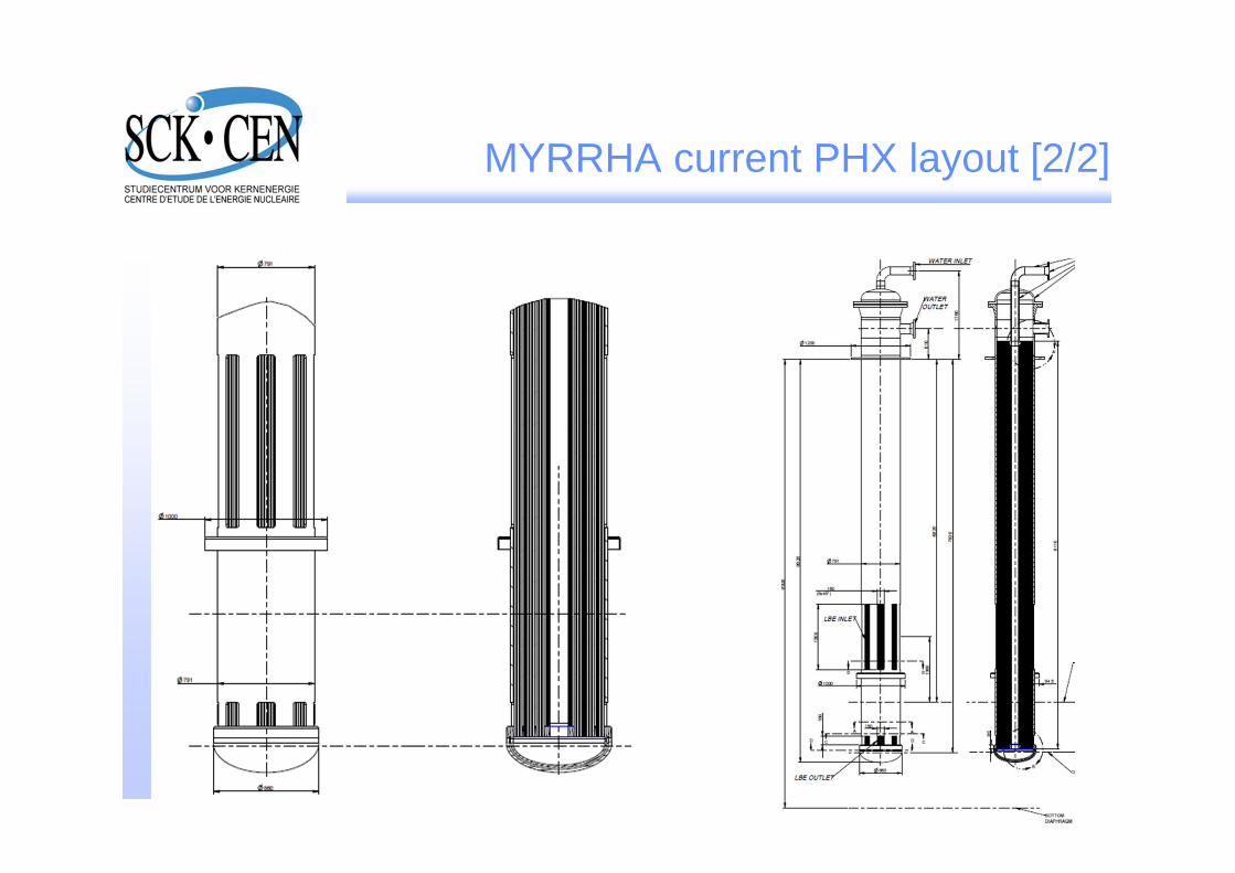
MYRRHA current PHX layout [2/2]
9

10
MYRRHA current PHX functional requirements
� Normal operation: reactor core power (and all other heat sources) removal � PHX operating in forced circulation regimes on both sides
� Decay Heat Removal (DHR) condition: accidental situation �reactor must be able to operate in passive conditions (natural circulation) to guarantee the DHR function (conservatively estimated at ~7% of the total core power)
� Safe Shutdown condition: during shutdown periods (decay heat power low enough to be compensated by thermal heat losses) � PHX to provide power to the primary LBE in order to prevent freezing (Safe Shutdown Temperature: 200 °C) operat ing in"reverse" mode

11
MYRRHA current PHX design choices
� Possible advantages:� No change in flow area � no phase separation, TH conditions preserved for the
whole tube length� Pressure drop � reduced need to orifice the water tubes for tube bundle flow
stabilization� Aspect ratio comparable to past LMFBRs � counter-current flow development
through the bundle� Possibility to adopt a wide inlet for LBE � full flow area for full power and partial
flow area (hot free surface at LBE inlet level) for DHR conditions� No need to adopt a double-walled structure for the upper part of the PHX shroud� Only one tube plate (� set of weldings) under LBE (upper tube plate above hot
free surface)� Relatively easy inspection and repair
� Possible disadvantages:� Tube length � stresses (weight, thermal-induced) in the tube plates� Upper fraction of tube bundle not in contact with LBE � free surface zone with
possible problems due to differential thermal expansion and level fluctuation (�thermal fatigue)
12
MYRRHA PHX calculation and verification
� Heat Treansfer Coefficient (HTC) and material properties correlations used for design:� For LBE properties and HTC correlation: LBE handbook (2007)� For steel properties: RCC-MRx (2010)
� PHX T/H performances verified with RELAP5 and TRACE system codes
� High level of agreement has been found between design and system code verification

13
MYRRHA current PHX control strategy [1/3]
� MYRRHA � research, experimental and material testing reactor
� Need to operate at different power levels when possible (in compatibility with performances required)
� Control issues arising when departing from T/H full power conditions:� Core parameters: Tin, Tout, ∆T, mass flow rate� Secondary side parameters: pw (and Tw), mass flow rate, exit quality
� Basing on the strategies comparison and taking into account the purpose and the needs of MYRRHA/FASTEF, it appears that the control solution involving a constant secondary loop conditions is preferable

14
MYRRHA current PHX control strategy [2/3]
� Advantages in keeping primary conditions constant:� Unchanged stresses for primary structural materials� Control rods operation not required to compensate temperature
feedbacks
� Advantages in keeping secondary conditions constant:� No pressure variations in secondary side � no need to design the
loop for pressure > 16 bar� SGTR accident condition mitigation � more margins for vessel
design, safety valves, rupture disks, etc…
� IPS thermally decoupled from primary system � No real need (differently than power reactors!) to keep constant primary system conditions
� Power level varied only between irradiation cycles (in function of IPS requirements) � no drawbacks!

15
MYRRHA current PHX control strategy [3/3]
� Control strategy proposed for PHX operation:� Constant secondary system condition� Primary system following load changes� Constant mass flow rate in both primary and secondary systems
100
150
200
250
300
350
400
450
0 10 20 30 40 50 60 70 80 90 100
Te
mp
era
ture
(°C
)
Power (MW)
PHX EoL operating temperatures at different power levels
EoL lower plenum temperature
EoL upper plenum temeprature
Core average exit temeprature

16
MYRRHA current PHXinspection and tube plugging
� Need to identify, inspect and plug failed PHX tubes
� Current available solution (Phénix experience):� PHX extraction� Lower plenum cut in the reactor hall (by remote
handling)� Tube plug� Re-weld� PHX insertion
� Inspection and plugging in-situ are considered
� Mechanical assessment of plugged pipe could show higher stresses than normal conditions

17
MYRRHA current PHXHTC and tubes thermal stresses
� Very preliminary mechanical assessment performed on the tangential stress in water tubes
� According to the HTC values evaluated, top wall temperatures are the following:� LBE side: 281 °C (292 °C at EoL)� Water side: 221 °C
� Thermal stresses intensity (~174 MPa in EoL conditions) is well below the 3Sm for AISI 316L (342 MPa)
� Use of different steel (2Cr 1Mo) with lower thermal deformation and higher Sm could represent an improvement

18
Flow instability problem
� Two kinds of instabilities can be found in a boiling (2φ) tube bundle of an HX:� Static instability� Dynamic instability
� Static instability (boiling channel problem): different pressure drop between liquid phase and vapor phase (assuming constant mass flow rate) � instability range in certain 2φ flow conditions (function of power, pressure, mass flow rate, quality, void fraction…) may appear in the heated channel
� Dynamic instability (tubes connected to plena problem): differences in mass flow rate distribution may appear among tubes � different flow regimes, obscillations, possible thermal fatigue, flow inversion, etc…

19
MYRRHA PHX static instability [1/3]

20
MYRRHA PHX static instability [2/3]
� Static instability:� Does not require time-dependent
approaches � can be evaluated with “steady-state" models without solving PDE systems
� Different approaches available, with different complexity
� Approach used: full non-equilibrium model
� Heated tube generally divided in 4 regions:� Single phase liquid� Subcooled nucleate boiling� Bulk boiling� Single phase vapor

21
MYRRHA PHX static instability [3/3]
� In nominal operation conditions, 99% of the heated length is in the Bulk boiling region
� At 7% of power (start DHR), about 85% of the heated length is in the Bulk boiling region
� Results to be confirmed with system code (RELAP5) model

22
MYRRHA PHXStatic instability – Results [1/3]
� In nominal conditions (full power, full mass flow rate), the working point of the system falls in a perfectly stable range
∆p = 1.15 bar
23
MYRRHA PHXStatic instability – Results [2/3]
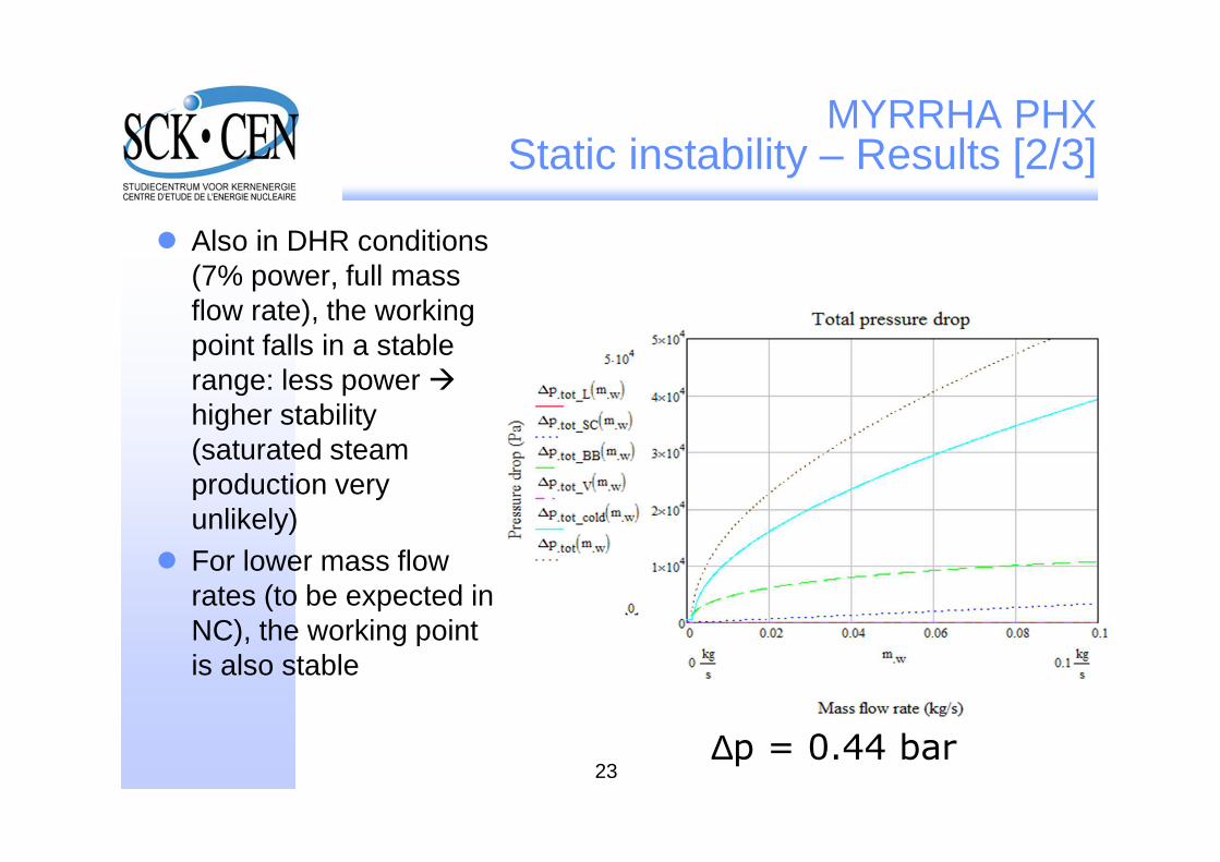
� Also in DHR conditions (7% power, full mass flow rate), the working point falls in a stable range: less power �higher stability (saturated steam production very unlikely)
� For lower mass flow rates (to be expected in NC), the working point is also stable
∆p = 0.44 bar
24
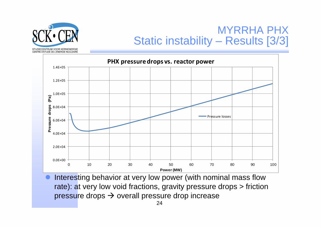
MYRRHA PHXStatic instability – Results [3/3]
� Interesting behavior at very low power (with nominal mass flow rate): at very low void fractions, gravity pressure drops > friction pressure drops � overall pressure drop increase
0.0E+00
2.0E+04
4.0E+04
6.0E+04
8.0E+04
1.0E+05
1.2E+05
1.4E+05
0 10 20 30 40 50 60 70 80 90 100
Pre
ssur
e d
rops
(P
a)
Power (MW)
PHX pressure drops vs. reactor power
Pressure losses

25
Dynamic instability
� Dynamic instability evaluation � time-dependent problem� A perturbation of any kind (power peak, mass flow rate
maldistribution, etc…) can change conditions in one pipe �consequences will be felt in other pipes
� Need to consider thermal inertiae of pipe walls for accurate thermal perturbation propagation
� Solution requiring time-space PDE coupled system � use of system codes (RELAP5) could be adviced
� Instability analysis methods could provide results about bundle stability without fully PDE system solution

26
Conclusions
� Further developements:� PHX inspection and tube plugging� PHX inlet – outlet thermal-hydraulic behaviour analysis and
design� Tube bundle spacer grids and their influence on the LBE flow� Complete mechanical assessment: water tubes, feed-water
inlet tube, upper and lower tube plates� Dynamic instability assessment� Cover and secondary system interfaces design

Copyright notice
Copyright © 2011 - SCK ����CEN
All property rights and copyright are reserved. Any communication or reproduction of this document, and any communication or use of its content without explicit authorization is prohibited. Any infringement to this rule is illegal and entitles to claim damages from the infringer, without prejudice to any other right in case of granting a patent or registration in the field of intellectual property.
SCK•CENStudiecentrum voor KernenergieCentre d'Etude de l'Energie Nucléaire
Stichting van Openbaar Nut Fondation d'Utilité Publique Foundation of Public Utility
Registered Office: Avenue Herrmann-Debrouxlaan 40 – BE-1160 BRUSSELOperational Office: Boeretang 200 – BE-2400 MOL