mycom s cpm153tekhar.com/programma/endress_hauser/analize/topcal s... · 2015-06-29 · mycom s...
TRANSCRIPT

TI404C/07/en/07.0671020146
Technical Information
Topcal S CPC310
Automation of pH and ORP measurement
Fully automatic measuring, cleaning and calibration system in hazardous
and non-hazardous areas
0 8 6
Application
Topcal S is a fully automatic measuring, cleaning and
calibration system for pH and ORP measurement in the
following areas:
• Process industry
• Water treatment
• Food industry
• Pharmaceutical industry
Your benefits
• Very high degree of safety
– system status messages with feedback to the control room
– in-process cleaning and calibration, no need to remove
electrode
– automatic cleaning on detection of electrode soiling
– industry-proven double-membrane pumps for transport of
buffer and cleaning solutions
• High measuring quality
– highest measuring accuracy
– optimum reproducibility of measurement results
– low tolerances in calibration
• High availability
– long electrode life thanks to interval measuring
– offline setup (optional): very simple setup on PC
– DAT module: very easy copying of setup to other devices
• Fast amortisation
– low purchase price
– low maintenance costs thanks to fully automatic cleaning
and calibration
– easy installation thanks to modular design
• Low maintenance even with heavily soiled and aggressive
media
• Communication via PROFIBUS PA (Profile 3.0) and HART

2
Function and system design
Measuring principle CPG310 control unit
The CPG310 control unit converts the commands of CPM153 into pneumatic signals and provides feedback
such as assembly position, bottle level and monitoring of compressed air. Buffer solutions and cleaner are
conveyed to the assembly by membrane pumps. The control unit has two additional freely configurable output
contacts. These contacts can be used to control pneumatic valves for conveyance of hot or aggressive media.
Mycom S CPM153 transmitter
The CPM153 transmitter is the central unit of the measuring system. It processes the measured values, acts as
the communication center and controls processes. It also controls the processes in the CPG310 and processes
its feedback via an interface.
Measuring system A complete measuring system consists of:
• Topcal S CPC310 including
– CPG310 control unit
– Mycom S CPM153 transmitter
– Rinse block
– Membrane pumps for transport of buffer and cleaning solutions
• Pneumatically controlled retractable assembly (e.g. Cleanfit series) with pneumatic or inductive limit
position switches
• pH/ORP sensor
• Measuring cable
• Buffer solutions and cleaner
a0006077
Complete measuring system (non-Ex area)
1
2
3
4
5
6
7
8
pH/ORP sensor
Cleanfit P assembly
Mycom S CPM153 transmitter
Special pH measuring cable
Power supply / control cable
Power supply for Mycom S CPM153
Power supply for CPG310 control unit
CPG310 control unit
9
10
11
12
13
14
15
Membrane pumps with cleaner and buffer bottles
Superheated steam / water / cleaner (optional)
Rinse block
Valve for rinse water control
Electrical wiring
Compressed air
Media (cleaner, buffer, superheated steam, etc.)
1 2 3
8
910
11
13
14
15
MEASMEAS CAL
DIAG PARAM
?
4 5
6
7
12

3
Connections of the
measuring system
To set up the complete measuring system, the following connections are required:
a0006078-en
Complete measuring system (Ex area)
A Message and control signals: assembly position, move assembly, program stop
B Hold input, six relay contacts, two current outputs 0/4 to 20 mA
1
2
3
4
5
6
7
pH/ORP electrode
Cleanfit P assembly
Mycom S CPM153-G transmitter
Power supply for Mycom S CPM153-G
Special pH measuring cable
Power supply / control cable for CPG310-G
CPG310-G control unit
8
9
10
11
12
13
14
Membrane pumps with cleaner and buffer bottles
Superheated steam, water, cleaner (optional)
Rinse block
Valve for rinse water control
Electrical wiring
Compressed air
Media (cleaner, buffer, superheated steam, etc.)
1 2 3 4
7
8
9
10
12
13
14
MEAS CAL
DIAG PARAMPARAM
?
5 6
11
A
B
zone 1zone 0/1
Atex zone Non-Ex
Electrical power supply
Mycom S CPM153:
Non-hazardous areas:
Hazardous areas:
100 to 230 V AC or 24 V AC/DC (depending on ordered version)
100 to 230 V AC or 24 V AC/DC (depending on ordered version)
CPG310 control unit:
Non-hazardous areas:
Hazardous areas:
100 to 230 V AC or 24 V AC/DC (depending on ordered version)
Power supplied via Mycom S
Compressed air
Specification: 4 to 6 bar (58 to 87 psi), filtered , 50 μm, free of oil and condensate
Connection: Bulkhead fitting OD 6 mm (0,24"), connection to the CPG310
control unit via supplied pressure reducing valve
Rinse water
Specification: Tap water, 3 to 6 bar (43,5 to 87 psi), filtered, 100 μm
Connection: Bulkhead fitting OD 6 mm (0,24"), connection to rinse block via
supplied water filter
4
! Note!
For a detailed description of the required line connections, see the Operating Instructions of Topcal S CPC310.
Cleaning and calibration Topcal S offers the following cleaning and calibration programs:
• Clean: Preset program for sensor cleaning
• Clean S: Preset program for cleaning and sterilisation of the sensor
• Clean C: Preset program for cleaning and calibration of the sensor
• Clean CS: Preset program for cleaning, calibration and sterilisation of the sensor
• User 3: Preset program for a fast system check
• User 1/2: Free program positions without preset program steps
All programs are freely configurable for optimum adaptation to your requirements. The preset programs serve
for faster configuration. You can include additional external valves in the programs for any medium,
e.g. superheated steam, cooling air, organic cleaner, etc.
Control of cleaning and calibration programs
You can choose between the following control types of the cleaning and calibration programs:
• Automatic:
Weekly program that automatically starts the cleaning or calibration programs selected for each weekday.
You can select any programs for any weekday.
• Cleaning:
Selection of program that is automatically started if an SCS alarm or a correspondingly configured error
message is triggered.
• Power failure program:
Selection of the programm that is started after a failure of the power supply, the compressed air, the rinse
water or the communication.
• External control:
Programs are started via an external process control system.
Interval program
This program allows you to start any cleaning or calibration program within defined intervals over a specified
period of time (max. 1 day).
Validation function
The validation function allows you to check if the currently measured value deviates from the set value and if
a calibration might be necessary.
Sealing water
This function allows you to start conveyance of sealing water into the rinse chamber. In processes with fibrous
or adhesive media, assemblies with ball valves, e.g. Cleanfit CPA473 or Cleanfit CPA475 are applied to block
the medium. To keep the rinse chamber free of medium, the sealing water valve opens automatically before
the assembly emerges from the process. The counterpressure in the rinse chamber caused by the sealing water
prevents the ingress of medium into the chamber. For this to work, the sealing water pressure must be greater
than the pressure of the medium.
Other functions Quick setup
To the first measuring value within 1 minute
After setting up the few parameters in the Quick Setup menu, the measuring point is ready to measure. The
first measured value is reliably displayed.
SCC (= Sensor Condition Check)
This function monitors the state of the electrodes or the degree of electrode ageing. The "Electrode OK", "Low
wear" or "Replace electrode" messages inform you on the state of the electrode. The electrode state is updated
after each calibration. When the "Replace electrode" message appears, an additional error message is triggered.
Assembly
Process connection: depending on the ordered assembly version, see Operating
Instructions of the assembly
Rinse block
Connection to rinse chamber of the
assembly:
G¼ or NPT ¼" male thread (depending on ordered version)

5
SCS (= Sensor Check System)
The sensor check system alerts to deviations of the pH glass impedance or reference impedance from the
normal range, thus indicating possible failure due to pH electrode blocking or damage.
In addition, the SCS detects glass breakage of glass electrodes and leakages of ISFET sensors.
PCS (= Process Check System)
This function checks the measuring signal for stagnation. If the measuring signal does not change for some time
(several measured values), an alarm is triggered. Soiling, blockage or similar could be the cause of such
behaviour.
Logbooks
There are several logbooks available. The last 30 entries are saved to an error log, an operation log and a
calibration log. The entries are displayed with their date and time.
Data log
The integrated data logs allow you to record two selectable parameters and display the results in real time. You
can retrieve the last 500 measured values with date and time of their recording. In this way, you can create a
graphic display of the process flow. This offers a quick way of checking the process and a good possibility of
optimizing pH control.
Easy control
The following control functions are implemented in the CPC310:
• Limit contact: two-point controller with hysteresis for simple temperature control, for example
• PID controller:
– for one and two-sided processes
– with freely adjustable P, I, D components
– includes configurable range-dependent gain (segmented curve)
– Distinction between batch and flow processes
• Manipulated variable output
The manipulated variable can be output as binary signal via the relays or via the current output:
– Binary signal via relays as PWM (pulse width modulation), PFM (pulse frequency modulation)
– Current output (0/4 to 20 mA): analog signal to control the actuator (for one or two actuator drives)
DAT module
The DAT module is a memory device (EEPROM) which is plugged into the terminal compartment of the
transmitter.
Using the DAT module, you can:
• save complete settings, logbooks and the logged data of the data logs of the Mycom S
• copy the complete settings to other Mycom S transmitters which have identical hardware functions.
This considerably reduces the effort to install or service several measuring points.
a0005506-en
Example for data log 1 (for parameter 1, pH is selected here)
1
2
3
4
Minimum display range (selectable to –2 pH)
Measured value found on the current scroll bar position
Scroll bar
Maximum display range (selectable to +16 pH)
5
6
7
Time when the measured value was recorded
Date of this measured value
Measured value curve
�
�
� �
�
�
�
2.00
7.54 12 15 3501 04 2001
12.00
Measure
Select

6
Off-line setup using the Parawin PC tool (Accessories)1)
Using the Parawin PC tool, you can:
1. Configure the whole measuring point on the PC in the familiar Windows environment.
2. Save the settings to the DAT module.
3. Plug the DAT module into a Mycom S and transfer the entire configuration to the transmitter (= complete
transmitter setup). Then you can set up other transmitters with the same configuration.
4. You can also use the DAT module to copy logbooks and data logs from the transmitter to your computer
for documentation purposes. You can then display the logged data in graphic form on your PC.
a0005507
Offline configuration with Parawin (1 - 2 -3) ⇒ Mycom
Offline data storage (3 -2 -1) ⇐ Mycom
Calibration and measurement Calibration options:
• Automatic calibration with automatic buffer recognition
Several buffer tables, e.g. according to DIN, Endress+Hauser, Merck and Riedel de Haën / Ingold are saved
in the transmitter. In addition, you can program further buffer tables. The transmitter automatically
recognizes the buffer value during calibration.
• Manual calibration
When calibrating manually, you can either perform a two-point calibration (zero point and slope) or a
one-point calibration, i.e. zero-point calibration of the pH electrode.
• Numeric calibration (data input)
The electrode data are entered using the keypad.
• Automatic transmission of calibration data from the sensor to the transmitter when your are using digital
sensors with Memosens technology.
• Calibration log
The data of the last 30 calibrations are saved to a list with date and time.
Accurate measurement through:
• Medium temperature compensation
This allows high-accuracy measurement over wide temperature ranges. This compensation type
compensates the temperature influence on the pH value of the medium.
• Isothermic intersection point compensation
This allows high-accuracy measurement even with temperature fluctuations. This compensation type
compensates the deviation betweeen isothermic intersection point and zero point of the electrode.
1) available from September 2006
DAT
PARAM
MEASMEAS CAL
DIAG
1 2 3

7
Input
Mycom S CPM153
Measured variables pH (analog or digital sensors)
ORP (analog or digital sensors)
Temperature
Measuring range
Input resistance > 1012 Ω (under nominal operating conditions, analog measured value transmission)
Input current for sensor circuit < 1.6 · 10-12 A (under nominal operating conditions)
Ex connection data
Cable specification for sensor
circuit
Current inputs 1 / 2 (passive,
optional)
Resistance input (active,
optional, non-Ex only)
Digital inputs E1 - E3
pH: –2 to 16 pH
ORP: –1500 to +1500 mV / -300 to +300 %
Temperature: -50 to +200 °C (-58 to 392 °F)
Sensor circuit with type of protection EEx ia IIC (optional). This circuit can be connected to sensors of
category 1G (zone 0) as well.
Maximum output voltage UO:
Maximum output current IO:
Maximum output PO:
Maximum outer capacity CO:
Maximum outer inductivity LO:
12.6 V DC
130 mA
198 mW
50 nF (with ISFET sensors 150 nF)
100 μH
0
Cable length (analog): max. 50 m (164 ft.)
Cable length (digital): max. 100 m (328 ft.)
Signal range:
Input voltage range:
4 to 20 mA
6 to 30 V
Intrinsically safe current inputs for connection to intrinsically safe electric circuits with type of
protection EEx ia IIC or EEx ib IIC (optional)
Maximum input voltage Ui:
Maximum input current Ii:
Maximum input Pi:
Maximum inner capacity Ci:
Maximum inner inductivity Li:
30 V DC
100 mA
3 W
1.1 nF
24 μH
0
Resistance ranges (selectable by the software): 0 to 1 kΩ0 to 10 kΩ
Input voltage:
Internal resistance:
10 to 50 V
Ri = 5 kΩ
Intrinsically safe optoelectronic coupler for connection with intrinsically safe electric circuits with type
of protection EEx ia IIC or EEx ib IIC
Maximum input voltage Ui:
Maximum inner capacity Ci:
Maximum inner inductivity Li:
30 V DC
negligible
negligible
0

8
CPG310 control unit
Digital inputs
Cable spec. for inductive limit
position switches
Output
Mycom S CPM153
Output signal 0/4 to 20 mA
Signal on alarm 2.4 or 22 mA in case of an error
Load active current output maximum 600 Ω (depending on operating voltage)
Output distribution
Passive current output
Ex connection data
Overvoltage protection acc. to EN 61000-4-5:1995
Auxiliary voltage output (for
digital inputs E1 - E3)
Input voltage
Internal resistance:
Minimum duration of start signal:
10 to 40 V
Ri = 5 kΩ500 ms
Intrinsically safe optoelectronic coupler for connection with instriniscally safe electric circuits with type
of protection EEx ia IIC or EEx ib IIC
Maximum input voltage Ui:
Maximum inner capacity Ci:
Maximum inner inductivity Li:
30 V DC
negligible
negligible
0
Cable length: max. 100 m (328 ft.)
pH: settable, 0 to 18 pH
ORP:
absolute:
relative:
settable, 300 to 3000 mV
settable, 0 to 600 %
Temperature: settable, 17 to 200 °C (62.6 to 392 °F)
Operating voltage range: 6 to 30 V
Intrinsically safe current output for connection with intrinsically safe electric circuits with type of
protection EEx ib IIC
Maximum input voltage Ui: 30 V DC
Maximum input current Ii: 100 mA
Maximum input Pi: 750 mW
Maximum inner capacity Ci: negligible
Maximum inner inductivity Li: negligible
0
Output voltage:
Output current:
15 V DC
max. 9 mA
Intrinsically safe current output circuit with type of protection EEx ib IIC
Maximum output voltage UO:
Maximum output current IO:
Maximum output PO:
Maximum outer capacity CO:
Maximum outer inductivity LO:
15.8 V DC
71 mA
1.13 W
50 nF
100 μH
0

9
Interface to CPG310
Relay contacts
Controller
Limit and alarm functions
Galvanic isolation Following circuits are at the same potential:
• Current output 1 and auxiliary voltage
• Current output 2 and resistance input
The remaining circuits are galvanically isolated from each other.
CPG310 control unit
Digital outputs
Power supply:
Output voltage:
Output current:
11.5 to 18 V DC
max. 60 mA
Communication: RS 485
Intrinsically safe current output circuit with type of protection EEx ib. IIC.
0Switching voltage:
Switching current:
Switching power:
Life span:
max. 250 V AC / 125 V DC
max. 3 A
max. 750 VA
≥ 5 million switching cycles
Intrinsically safe relay contact circuits for connection with intrinsically safe electric circuits with type
of protection EEx ia IIC or EEx ib IIC
Maximum input voltage Ui:
Maximum input current Ii:
Maximum input Pi:
Maximum inner capacity Ci:
Maximum inner inductivity Li:
30 V DC
100 mA
3 W
1.1 nF
24 μH
0
Function (selectable): Pulse-length controller (PWM)
Pulse-frequency controller (PFM)
Three-point step-controller (3-point step)
Analog (via current output)
Controller behavior:
Control gain KR:
Integral action time Tn:
Derivative action time Tv:
Max. frequency with pulse-frequency controller:
Max. period with pulse-length controller:
Minimum switch-on period with pulse-length controller:
P / PI / PID
0.01 to 20.00
0.0 to 999.9 min
0.0 to 999.9 min
120 min-1
1 to 999.9 s
0.4 s
Setpoint adjustments: -2.00 to 16.00 pH
Hysteresis for switching contacts:
pH:
ORP absolute:
ORP relative:
0.1 to 18 pH
10 to 100 mV
1 to 3000 %
Alarm delay: 0 to 6000 s
Optocoupler, max. switching voltage:
Max. switching current:
Max. switching power:
30 V
100 mA
3 W
Intrinsically safe optoelectronic control outputs for connection of intrinsically safe electric circuits with
type of protection EEx ia IIC or EEx ib IIC
Maximum input voltage Ui:
Maximum input current Ii:
Maximum input power Pi:
Maximum inner capacity Ci:
Maximum inner inductivity Li:
30 V DC
100 mA
1 W
negligible
negligible

10
Control for external valves
Power supply
Wiring diagram
a0005788-en
Wiring in non-Ex areas
Switched compressed air output:
Max. pressure: as supply pressure
�
AD 6 / ID 4
A
B
+
–
PE
A
B
L+
L–
91
89
87
61
85
83
65
81
93
92
90
88
62
86
84
66
82
94
S S
+
–
89
11 1112
131312
85
41
51
47
54
57
44
93
81
90
86
42
52
48
55
58
45
94
82+
+
+
pH
Ref. Ref.
n.c. SRC
DRN
31
32
33
34
+
-
-
PA/PM
PA/PM
mA
mA+
+
15 V
PE
PE
)
)
P2
P4
P6
P1
P3
P5
(optional)
+
+
+
+
+
+
+
+
+
CPG310Mycom CPM153
Temp. 1Temp. 1
E1: ext. Hold*
E2: Chemoclean"Clean"*
E3: Chemoclean"User"*
bin. 2
bin. 1
bin. 0
BN
WH
GN
YE
N/L–L/L+
N/L–L/L+
2
3
5
6
CPA475
S
96
97
BN
WH
GN
YE
87
88
PE�
42
41
46
45
57
58
48
47
52
51
55 56 11 12 13 14 71 72 75 76
1 2 3
A B C
10
...40
V
J J
Alarm relay(NAMUR: Failure
Relay 1(NAMUR: Mainten. requ.)
Relay 2(NAMUR: Function control)
Relay 3
Relay 4
Relay 5
Power supply
CPGcomm.
12V DC
Currentoutput 2
Currentoutput 1
pH electrode or ISFET pH sensor
Power supplyoutput*
Assemblymeasuring
Assemblymeasure
n.c.
Assemblyservice
Automatic stop
Assemblyservice*
Compressedair supply4 ... 6 bar,filtered 50 µm,free of oil andcondensate
Valve 2
Valve 1
Power supply
Sta
rtpro
gra
mm
e1-8
(bin
ary
)
Levelcheck
electric line
compressed air/medium
n.c.: do not connect!
Installation and connectionby operator
(operator supply)
Digital sensor
Pressurized steam,water, cleaner
Contr
olofm
em
bra
ne
pum
ps
Rinse block
Wate
r
Assem
bly
Feedback
measure
Feedback
serv
ice
2/2
-way
valv
e
Rin
se
air
Multihose coupling
Multih
ose
couplin
g
Buffer 1Cleaner Buffer 2
Pneum
atic
connection

11
a0005789-en
Wiring in Ex areas
A
B
+
–
S
A
B
+
–
pH Ref.PA 11 12 13
+
–
85
54
44
93
81
86
55
45
94
82+
+
31
32
33
34
+
-
-
+
Temp.
pH
L+
L+
L– ext
L– ext
L+
L+
L– ext
L–
PEN/L–L/L+
41
51
47
57
42
52
48
58
NA
MU
R
92
90
88
65
86
61
84
82
94
93
91
89
66
87
62
85
83
81
Ex ib
P2
P4
P6
P1
P3
P5
57
58
48
47
52
51
1 2 3
A B C
55 56 1112 13 14 71 72 75 76
42414645
5
63
2
Digitalinput E1
Digitalinput E2
Relay 4
Relay 5
Current output 2
Current output 1
pHelectrode Temperature
+
-
Assemblymeasure
Assemblymeasure
Pause
Assemblyservice
Assemblyservice
bin. 2
bin. 1
bin. 0
Sta
rtp
rog
ram
1-8
(bin
ary
)
CPG310-GMycom CPM153-G
externalhold
Power supply
Control foradditional valve 1
Control foradditional valve 2
ib
ib
ib
ib
ib
ib
ib
ib
ib
ib
ib
ib
ib
ib
ib
ib
ib
ia
e.g. pressurewater, hot
Pressure reducingvalvePneumatic connection
e.g. 6 xSTAHLdigital output9175/10-14-11-11s
e.g. 3 xSTAHL 9170/10-11-11s
Automaticstop
Power supply
Failure
Powersupply
Maintenance
Function control
pH limit value
AcidBase
Water
Air
Electric line
Compressed air
Medium
Le
ve
lch
eck
Co
ntr
olo
fm
em
bra
ne
pu
mps
Mu
ltih
ose
co
up
ling
Asse
mb
ly
Fe
ed
ba
ck
me
asu
re
Fe
ed
ba
ck
se
rvic
e
2/2
-wa
yva
lve
Rin
se
air
Multihose coupling
Cleaner Buffer 1 Buffer 2

12
Mycom S CPM153
Supply voltage
Cable specification
Power consumption maximum 10 VA
Separation voltage between
galvanically isolated circuits
276 Vrms
Interface connection data Mycom S has one alarm and five additional contacts.
You can assign functions to the available contacts via the software. The "Active open" and "Active closed"
contact types can also be switched by the software.
You can assign up to three relays to the controllers.
! Note!
If you use NAMUR contacts (acc. to recommendations of the association for process control engineering of the
chemical and pharmaceutical industry), the contacts are set to the relays as follows:
Frequency 47 to 64 Hz
Ex connection data
Version CPM153-xxxx0xxxx
Version CPM153-xxxx8xxxx
100 to 230 V AC +10/-15 %
24 V AC/DC +20/-15 %
Maximum cable cross-section: 2.5 mm2 (i 14 AWG)
Relay Assignment
NAMUR on
Assignment
NAMUR off
Terminal
ALARM Failure Alarm
RELAY 1 Warning when maintenance
required
free connectable
RELAY 2 Function check free connectable
Connection data for 12 V supply
Maximum output voltage UO:
Maximum output current IO:
Maximum output power PO:
Maximum outer capacity CO:
Maximum outer inductivity LO:
18.5 V
100 mA
1.53 W
150 nF
150 μH
0

13
CPG310 control unit
Supply voltage
Cable specification
Power consumption max. 12 VA
Separation voltage between
galvanically isolated circuits
276 Vrms
Frequency 47 to 64 Hz
Ex connection data
Version CPC310-xxxxx0xxxxx: 230 V AC +15/-15 %
Version CPC310-xxxxx1xxxxx: 110 to 115 V AC +15/-15%
Version CPC310-xxxxx8xxxxx: 24 V AC/DC +20/-15 %
Maximum cable cross-section: 2.5 mm2 (i 14 AWG)
Ex versions are powered by the CPM153 transmitter (see data above).
0

14
Connection examples
a0005851-en
Connection example, double-sided neutralisation, pH limit value, NAMUR pin assignment, pH and temperature at current
outputs, 2 additional valves, external control via PCS, assembly status display
A
B
+
–
S
A
B
+
–
pH Ref.PA 11 12 13
+
–
85
54
44
93
81
86
55
45
94
82+
+
31
32
33
34
+
-
-
+
Temp.
pH
PEN/L–L/L+
41
51
47
57
42
52
48
58
NA
MU
R
92
90
88
65
86
61
84
82
94
93
91
89
66
87
62
85
83
81
P2
P4
P6
P1
P3
P5
57
58
47
48
51
52
1 2 3
A B C
55 56 1112 13 14 71 72 75 76
42414645
5
63
2
max. 30 V
(max 3 W)
(max 3 W)
PE)
N/L–L/L+
Digitalinput E1
Digitalinput E2
Relay 4
Relay 5
Current output 2
Current output 1
pHelectrode Temperature
+
-
Assemblymeasure
Assemblymeasure
Pause
Assemblyservice
Assemblyservice
bin. 2
bin. 1
bin. 0
Sta
rtp
rog
ram
1-8
(bin
ary
)
CPG310-GMycom CPM153-G
externalhold
Power supply
Control foradditional valve 1
Control foradditional valve 2
ia
e.g. pressurewater, hot
Pressure reducingvalvePneumatic connection
Automaticstop
Power supply
Failure
Powersupply
Maintenance
Function control
pH limit value
AcidBase
Water
Air
Electric line
Compressed air
Medium
Levelcheck
Contr
olofm
em
bra
ne
pum
ps
Multih
ose
couplin
g
Assem
bly
Feedback
measure
Feedback
serv
ice
2/2
-way
valv
e
Rin
se
air
Multihose coupling
Cleaner Buffer 1 Buffer 2
PCS
Power supply

15
Performance characteristics
Reference temperature 25 °C (77 °F), settable with medium temperature compensation
Measured value resolution
Measurement deviation2)
Repeatability max. 0.1 % of measuring range
Zero point offset range
Slope adjustment
Offset
Assignment with ORP relative settable, Δ for 100 % = 150 to 2000 mV
Installation
Installation instructions
CPM153
Wall mounting
" Caution!
• Check that the temperature does not exceed the maximum permitted temperature range (-20 to +60 °C
(-4 to +140 °F). Install the device in a shady location. Avoid direct sunlight.
• Install the field instrument so that the cable entries always point downwards.
a0003953
Dimensions for wall mounting, fixing screw: Ø 6 mm (0.24"), wall plug: Ø 8 mm (0.31")
1 Fixing drill holes
2 Plastic cover caps
pH:
ORP:
Temperature:
0.01 pH
1 mV / 1 %
0.1 K
2) acc. to DIN IEC 746-1, under nominal operating conditions
Display
pH:
ORP:
Temperature:
max. 0.2 % of measuring range
max. 1 mV
max. 0.5 K
Current output:
Current inputs:
Resistance input:
max. 0.2 % of current range end value in addition to
display deviation
max. 1 % of measuring range
max. 1 % of measuring range
pH:
ORP:
-2 to +16 pH
-200 to +200 mV
pH: 5 to 99 mV/pH
ORP:
Temperature:
±120 mV
±5 K154
(6.0
6)
100 (3.94)
247
(9.7
2)
142 (5.59)
167 (5.57)
Ø8
(0.3
1)
2
1
mm (inch)

16
Panel and post mounting
! Note!
To mount the transmitter to horizontal and vertical posts or pipes (max. Ø 70 mm (2.76")) and for panel
mounting, use the supplied mounting kit.
a0003955
Mounting kit
Mount the parts of the mounting kit on the back of the housing as shown in the figure below.
a0005508
Panel mounting and post or pipe mounting
1 Panel mounting
2 Post mounting horizontal
3 Post mounting vertical
Panel mounting:
To achieve airtight panel mounting, you need to use an additional flat gasket (see "Accessories").
Required installation cutout: 161 x 241 mm (6.34" x 9.49")
Installation depth: 134 mm (5.28")
Post or pipe mounting:
Post / pipe diameter: max. 70 mm (2.76")
80 (3.15)
80(3
.15)
Ø70
(2.7
6)1 2 3
mm (inch)
17
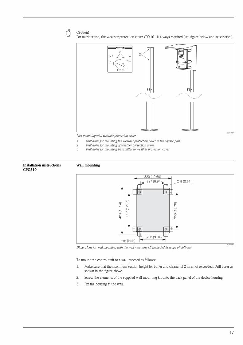
" Caution!
For outdoor use, the weather protection cover CYY101 is always required (see figure below and accessories).
a0003957
Post mounting with weather protection cover
1 Drill holes for mounting the weather protection cover to the square post
2 Drill holes for mounting of weather protection cover
3 Drill holes for mounting transmitter to weather protection cover
Installation instructions
CPG310
Wall mounting
a0004861
Dimensions for wall mounting with the wall mounting kit (included in scope of delivery)
To mount the control unit to a wall proceed as follows:
1. Make sure that the maximum suction height for buffer and cleaner of 2 m is not exceeded. Drill bores as
shown in the figure above.
2. Screw the elements of the supplied wall mounting kit onto the back panel of the device housing.
3. Fix the housing at the wall.

18
Maximum line and hose lengths
The figure below shows the maximum permissible distances between Topcal S system components.
a0006069
Maximum distances between system components
* when using the supplied standard multihoses
** depending on ordered multihose version
Environment
Ambient temperature range -10 to +55 °C (14 to 131 °F)
-10 to +50 °C (14 to 122 °F) (Ex)
Ambient temperature limits –20 to +60 °C (-4 to +140 °F)
-10 to +50 °C (+14 to +122 °F) (Ex)
Storage temperature –30 to +80 °C (-22 to +176 °F)
Electromagnetic compatibility Interference emission acc. to EN 61326: 1997 / A1: 1998; class B resources (housing sector)
Interference emission acc. to EN 61326: 1997 / A1: 1998; appendix A (industrial sector)
max. 2.5 m (8.20 ft)*
max. 5 m (16.4 ft)
max. 5/10 m(max. 16.4/32.8 ft)**
MEAS CAL
DIAG PARAMPARAM
?
max. 200 m (656 ft)

19
Ingress protection CPM153
IP 65
CPG310
IP 54
Relative humidity 10 to 95%, non condensing
Safety requirements Complies with general safety requirements acc. to EN 61010.
Complies with NAMUR recommendations NE 21: 08/1998.
Process
Process temperature range 0 to 50 °C (32 to 122 °F)
Mechanical construction
Design, dimensions CPM153
cxm153-dim.cdr
Mycom S dimensions
20
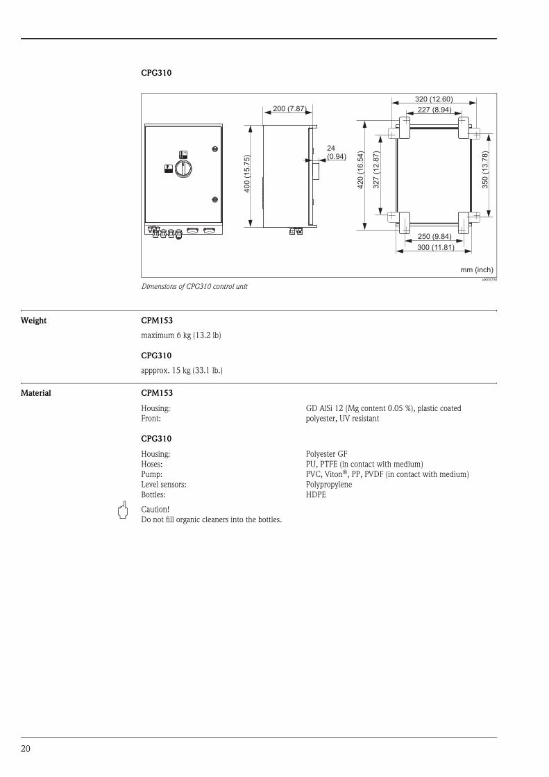
CPG310
a0005790
Dimensions of CPG310 control unit
Weight CPM153
maximum 6 kg (13.2 lb)
CPG310
appprox. 15 kg (33.1 lb.)
Material CPM153
CPG310
" Caution!
Do not fill organic cleaners into the bottles.
300 (11.81)400
(15.7
5)
250 (9.84)
350
(13.7
8)24
(0.94)
200 (7.87)
320 (12.60)
227 (8.94)
327
(12.8
7)
420
(16.5
4)
mm (inch)
Housing:
Front:
GD AlSi 12 (Mg content 0.05 %), plastic coated
polyester, UV resistant
Housing:
Hoses:
Pump:
Level sensors:
Bottles:
Polyester GF
PU, PTFE (in contact with medium)
PVC, Viton®, PP, PVDF (in contact with medium)
Polypropylene
HDPE

21
Human interface
Display and operating
elements CPM153
Backlit LC graphic display with dot matrix, 128 x 64 dots
The display shows the current measured value and the temperature, i.e. the most important process data at a
glance. In the configuration menu, online help pages help you to enter suitable configuration parameters.
Operating functions Four main menus are available for instrument operation:
• Measurement
• Configuration
• Calibration
• Diagnosis
Press the Ò, Ñ, Ï and Ð keys to switch to the appropriate menu. The submenus are displayed in plain
text and the selected elements are displayed in reverse video. Use the arrow keys to select elements and to edit
numeric values.
Access codes To protect the transmitter from unintended or undesired modification of the configuration and calibration data,
four-digit access codes can be defined. Access authorization has the following levels:
• Read-only level (accessible without code)
The complete menu can be viewed. The configuration cannot be changed. Calibration is not possible. Only
the controller parameters can be changed in the "DIAG" menu branch.
• Maintenance level (can be protected by the service code)
This code permits calibration. It also permits to operate the temperature compensation menu command and
to view test functions and internal data.
• Specialist level (can be protected by the specialist code)
All menus are accessible for modification.
! Note!
As long as no codes are defined, all functions are freely accessible.
a0004120-en
1
2
3
4
5
6
7
Current menu
Current measured variable
Select: Arrow keys for scrolling through the menu;
"E" for browsing; note for cancelling
Ò Measuring mode key
Ï Calibration mode key
Ð Diagnosis mode key
Ñ Configuration mode key
8
9
10
11
12
13
HOLD display, if HOLD is active
Current main measured value
"Failure", "Warning", if NAMUR contacts are active
Labeling strip
TVW Arrow keys for selection and enter
F Enter key
MEAS CAL
DIAG PARAM
1
2
3
9
10
4
5 12
136
11
7
8
HOLD
Failure
7.54
Measure
pH
ATCTemperature 25.0 °C
Select [ ¯]

22
Offline configuration using
Parawin (Option)3)
The PC tool Parawin enables you to configure your measuring point offline on a PC using a simple,
self-explaining menu structure (see example below). Write the configuration data to the DAT module via the
RS 232 interface of the PC and then plug the DAT module into the transmitter.
a0005582
Parawin menu structure
Certificates and approvals
4 symbol Declaration of conformity
The product meets the legal requirements of the harmonized European standards.
The manufacturer confirms compliance with the standards by affixing the 4 symbol.
Ex approval Depending on ordered version:
• ATEX II (1) 2G, EEx em ia/ib IIC T4
• FM NI Class I, Division 2, Groups A, B, C, D; sensor IS Class I Division 1, Groups A, B, C, D
FM DIP Class II, III, Division 1, Groups E, F, G; sensor IS Class I Division 1, Groups A, B, C, D
• FM NI Class I, Division 2, Groups A, B, C, D
FM DIP Class II, III, Division 1, Groups E, F, G
• CSA Class I, Division 2; sensor IS Class I Division 1
• EC system approval
3) avalailable from September 2006

23
Ordering information
Product structure Approvals
A Basic equipment: non-Ex
G With ATEX approval, ATEX II (1) 2G EEx, em ib[ia] IIC T4
O With FM approval Cl. I, Div. 2, with NI input and output circuits, sensor IS Cl. I, Div. 1
P With FM approval Cl. I, Div. 2, with NI input and output circuits
S With CSA approval Cl. I, Div. 2, sensor IS Cl. 1, Div. 1
Materials: rinse block, O-ring, connection
00 PVDF, Viton, G¼ male
01 PVDF, Viton, NPT ¼", male
02 PVDF, Kalrez, G¼, male
03 PVDF, Kalrez, NPT ¼", male
10 Stainless steel 1.4404 (AISI 316L), Viton, G¼, male
11 Stainless steel 1.4404 (AISI 316 L), Viton, NPT ¼", male
12 Stainless steel 1.4404 (AISI 316 L), Kalrez, G¼, male
13 Stainless steel 1.4404, (AISI 316 L) Kalrez, NPT ¼", male
Measurement input Mycom S
1 1 measuring circuit for glass electrodes, pH/ORP and temperature
2 1 measuring circuit for glass electrodes / ISFET sensors, pH/ORP and temperature
5 1 measuring circuit for digital Memosens sensors, pH/ORP and temperature
Measurement output Mycom S
A 2 current outputs 0/4 to 20 mA, passive (Ex and non-Ex)
B 2 current outputs 0/4 to 20 mA, active (non-Ex)
C HART with 2 current outputs 0/4 to 20 mA, passive
D HART with 2 current outputs 0/4 to 20 mA, active
E PROFIBUS PA without current outputs
Power supply
0 230 V AC
1 110 to 115 V AC
8 24 V AC/DC
Language versions
A English / German
B English / French
C English / Italian
D English / Spanish
E English / Dutch
Cable connection
0 Cable glands M 20 x 1.5
1 Threads NPT ½"
3 Cable glands M 20 x 1.5, PROFIBUS-PA M12 plug
4 Threades NPT ½", PROFIBUS-PA M12 plug
Multihose length
0 5 m (16.4 ft.)
1 5 m (16.4 ft.) with electrical heating
2 10 m (32.8 ft.)
3 10 m (32.8 ft.) with electrical heating
Additional options
0 Standard version
1 Preparation for CYC310 housing
9 Special version acc. to customer specifications
Adjustment
A Factory setup
B IQ/OQ template, German
C IQ/OQ template, English
D Standard FAT, German
E Standard FAT, English
CPC310- complete order code

24
Scope of delivery The scope of delivery comprises:
• 1 transmitter Mycom S CPM153
• 1 control unit CPG310
• 1 rinse block with brackets for assembly mounting
• 4 multihoses
• 3 double-membrane pumps with canisters, for buffer and cleaner conveyance
• 2 technical buffer solutions pH 4.00 and 7.00
• 1 communication / supply cable CPG310 / Mycom S CPM153
• 3 level sensors, complete with cables from CPG310 to bottles
• 1 pressure reduction valve with manometer
• 1 water filter
• 1 device identification card
• 1 Operating Instructions, English
• Accessories, if ordered
Accessories
Offline configuration with
Parawin
• Parawin
Graphical PC software for offline configuration of the measuring point at the PC. The language is selectable.
Required operating systems: Windows NT/95/98/2000.
The offline configuration tool consists of:
• a DAT module
• DAT interface (RS 232)
• Software
Order no.: 51507133 (Mycom S only)
Order no.: 51507563 (Topcal S, Topclean S, Mycom S)
DAT module • Additional memory device for saving or copying complete settings, logbooks and the data logs;
Order no.: 51507175
Flat gasket • Flat gasket for air-tight panel mounting of the Mycom S
Order no.: 50064975
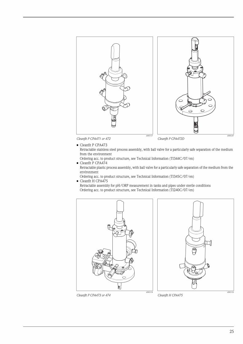
Assemblies (selection) • Cleanfit P CPA471, version CPA471-xxxxxx3/4
Compact retractable stainless steel assembly for installation in tanks and pipes, manual or pneumatic
operation
Ordering acc. to product structure, see Technical Information (TI217C/07/en)
• Cleanfit P CPA472, version CPA472-xxxxxx3/4
Compact retractable plastic assembly for installation in tanks and pipes, manual or pneumatic operation
Ordering acc. to product structure, see Technical Information (TI223C/07/en)
• Cleanfit P CPA472D, version CPA472D-xxxxxxx3/4/5
Retractable assembly for pH/ORP measurement in tanks and pipes, manual or pneumatic operation,
heavy-duty version made of highly resistant materials, see Technical Information (TI403C/07/en)
25
• Cleanfit P CPA473
Retractable stainless steel process assembly, with ball valve for a particularly safe separation of the medium
from the environment
Ordering acc. to product structure, see Technical Information (TI344C/07/en)
• Cleanfit P CPA474
Retractable plastic process assembly, with ball valve for a particularly safe separation of the medium from the
environment
Ordering acc. to product structure, see Technical Information (TI345C/07/en)
• Cleanfit H CPA475
Retractable assembly for pH/ORP measurement in tanks and pipes under sterile conditions
Ordering acc. to product structure, see Technical Information (TI240C/07/en)
a0003137
Cleanfit P CPA471 or 472a0006247
Cleanfit P CPA472D
a0003138
Cleanfit P CPA473 or 474a0003136
Cleanfit H CPA475

26
Sensors Glass electrodes
• Orbisint CPS11/CPS11D
pH electrode for process applications, with PTFE diaphragm, Memosens technology as option;
Ordering acc. to product structure, see Technical Information (TI028/C07/en)
• Orbisint CPS12/CPS12D
ORP electrode for process applications, with PTFE diaphragm, Memosens technology as option;
Ordering acc. to product structure, see Technical Information (TI367/C07/en)
• Ceraliquid CPS41/CPS41D
pH electrode with ceramics diaphragm and liquid KCl electrolyte, Memosens technology as option;
Ordering acc. to product structure, see Technical Information (TI079/C07/en)
• Ceraliquid CPS42/CPS42D
ORP electrode with ceramics diaphragm and liquid KCl electrolyte, Memosens technology as option;
Ordering acc. to product structure, see Technical Information (TI079/C07/en)
• Ceragel CPS71/CPS71D
pH electrode with double chamber reference system and integrated bridge electrolyte,
Memosens technology as option;
Ordering acc. to product structure, see Technical Information (TI245/C07/en)
• Ceragel CPS72/CPS72D
ORP electrode with double chamber reference system and integrated bridge electrolyte, Memosens
technology as option;
Ordering acc. to product structure, see Technical Information (TI374/C07/en)
• Orbipore CPS91/CPS91D
pH electrode with open aperture for media with high dirt load, Memosens technology as option;
Ordering acc. to product structure, see Technical Information (TI375C/07/en)
ISFET sensors
• Tophit CPS471/CPS471D
Sterilizable and autoclavable ISFET sensor for food and pharmaceuticals, process technology, water
treatment and biotechnology;
Ordering acc. to product structure, see Technical Information (TI283/C07/en)
• Tophit CPS441/CPS441D
Sterilizable ISFET sensor for media with low conductivity, with liquid KCl electrolyte;
Ordering acc. to product structure, see Technical Information (TI352/C07/en)
• Tophit CPS491/CPS491D
ISFET sensor with open aperture for media with high dirt load;
Ordering acc. to product structure, see Technical Information (TI377/C07/en)
Connection accessories • CPK1 special measuring cable
For pH/ORP electrodes with GSA plug-in head
Ordering acc. to product structure, see Technical Information (TI118C/07/en)
• CPK9 special measuring cable
For pH/ORP sensors with TOP68 plug-in head, for high-temperature and high-pressure applications, IP 68
Ordering acc. to product structure, see Technical Information (TI118C/07/en)
• CPK12 special measuring cable
For pH/ORP glass electrodes and ISFET sensors with TOP68 plug-in head
Ordering acc. to product structure, see Technical Information (TI118C/07/en)

27
• CYK10 Memosens data cable
For digital sensors with Memosens technology
Ordering according to product structure, see below
CYK12 measuring cable
• Non-terminated cable for extension of sensor cables, used in combination with CPK1, CPK9 and CPK12
• Coax and 5 pilot wires
• Sold by the meter:
– Non-Ex version, black: order no. 51506598
– Ex-version, blue: order no. 51506616
CYK81 measuring cable
• To lengthen the cable of e.g. Memosens, CUS31/CUS41
• 2 wires, twisted pair with shield and PVC-sheath (2 x 2 x 0.5 mm2 + shield)
• Sold by the meter, order no. 51502543
• Junction box VBE Ex zone 0
for connection of up to 3 single lines of Ex zone 0 sensors
order no. 50003993
Junction box VBM
• For cable extension, with 10 terminals
• IP 65 / NEMA 4X
• Material: aluminum
• Order numbers:
– cable entry Pg 13.5: 50003987
– cable entry NPT ½": 51500177
Junction box VBA
• With 10 high-impedance terminals, protection class: IP 65 (i NEMA 4X)
• Material: polycarbonate
• Order no. 50005276
Junction box RM
• To lengthen the cable for Memosens or CUS31/CUS41
• With 2 x PG 13.5
• IP 65 (i NEMA 4X)
• Order no. 51500832
Certificates
A Standard, non Ex
G ATEX II 1G EEx ia IIC T6/T4
Cable length
03 Cable length: 3 m (9.8 ft)
05 Cable length: 5 m (16 ft)
10 Cable length: 10 m (33 ft)
15 Cable length: 15 m (49 ft)
20 Cable length: 20 m (66 ft)
25 Cable length: 25 m (82 ft)
88 ... m length
89 ... ft length
Ready-made
1 Wire terminals
CYK10- complete order code

28
Mounting accessories • Weather protection cover CYY101 for mounting of field housing, for outdoor installation
material: stainless steel 1.4031;
order no. CYY101-A
a0005585
Weather protection cover for field instrument
• Round post fixture to fix the stainless steel weather protection cover CYY101 to vertical or horizontal posts
with diameters of up to 70 mm (2.76");
Order no. 50062121
Buffer solutions Technical buffer solutions, accuracy 0.02 pH, acc. to NIST/DIN
• pH 4.0 red, 100 ml (3.4 fl.oz.), order no. CPY2-0
• pH 4.0 red, 1000 ml (34 fl.oz.), order no. CPY2-1
• pH 7.0 green, 100 ml (3.4 fl.oz.), order no. CPY2-2
• pH 7.0 green, 1000 ml (34 fl.oz.), order no. CPY2-3
Technical buffer solutions for single use, accuracy 0.02 pH, acc. to NIST/DIN
• pH 4.0 20 x 20 ml (0.68 fl.oz.), order no. CPY2-D
• pH 7.0 20 x 20 ml (0.68 fl.oz.), order no. CPY2-E
Technical buffer solutions for ORP electrodes
• +220 mV, pH 7.0, 100 ml (3.4 fl.oz.); order no. CPY3-0
• +468 mV, pH 0.1, 100 ml (3.4 fl.oz.); order no. CPY3-1
KCl-electrolyte solutions for liquid filled electrodes
• 3.0 mol, T = -10 ... 100 °C (14 ... 212 °F), 100 ml (3.4 fl.oz.), order no. CPY4-1
• 3.0 mol, T = -10 ... 100 °C (14 ... 212 °F), 1000 ml (34 fl.oz.), order no. CPY4-2
• 1.5 mol, T = -30 ... 100 °C (-22 ... 266 °F), 100 ml (3.4 fl.oz.), order no. CPY4-3
• 1.5 mol, T = -30 ... 100 °C (-22 ... 266 °F), 1000 ml (34 fl.oz.), order no. CPY4-4
300 (11.81)
320
(12.6
0)
270 (10.63)
mm (inch)
a0005091
Round post fixture for CYY101
M6
55 (2.17)
66 (2.60)
70
(2.7
6)
Ø8 (0.31)
30 (1.18)
90
(3.5
4)
mm (inch)

29
CYC310 housing Housing for Topcal S CPC310, with rack for buffer and cleaner solutions. Operating panel with alarm LED and
lock for program start and assembly moving. For application in hazardous and non-hazardous areas.
Material: Plastic or stainless steel
• Plastic version: Window for Mycom S and Memograph S
• Stainless steel version without Memograph S: Window for Mycom S
• Stainless steel version with Memograph S: Window for Memograph S
a0004967
Dimensions of CYC310 housing, stainless steel version
a0006254
Interior view of CYC310 housing, stainless steel version
1
2
3
4
5
Mycom S CPM153
Control unit
Cable glands
Multihose connections
Rack
6
7
8
9
Distributing box
Window for display
Membrane pumps f. buffer and cleaner conveyance
buffer and cleaning solutions
1
2
3
4
5
6
7
8
9
1003.5 (39.51)
39.5(1.56)
24.7(0.97)
837
(32.9
5)
25.5
(1.0
0)
25.7(1.01)
493 (19.41)
63.3 (2.49)
17.8 (0.70) 240(9.45)
240(9.45)
240(9.45)
240(9.45)
5 x Ø 8.5(5 x Ø 0.33)
73
6.5
(29
.00
)15
(0.5
9)
9(0.35)960 (37.80)
mm (inch)

30
a0004966
Dimensions of CYC310 housing, plastic housing
Ordering information
800 (31.5)300(11.81) 750 (29.53)
1000
(39.3
7)
950
(37.4
)
40(1.57)
Ø 8(Ø 0.31)
mm (inch)
Certificates
A Basic version: non-hazardous area
G With ATEX approval, ATEX II (1) 2G EEx, em ib[ia] IIC T4
O With FM approval Cl. I, Div. 2, with NI input and output circuits, sensor IS Cl. I, Div. 1
P With FM approval Cl. I, Div. 2, with NI input and output circuits
S With CSA approval Cl. I, Div. 2, sensor IS Cl. 1, Div. 1
Power supply
1 230 V AC
2 110 to 115 V AC
3 24 V AC/DC
Materials
A Plastic
B Stainless steel 1.4301 (AISI 304)
Heating
1 Without electrical heating
2 With electrical heating
Data log function
A Without Memograph S
B With Memograph S
Allocation
1 Empty housing, without CPC310
2 Separate item of CPC310
Additional options
1 Basic version
CYC310- complete order code

31
Operating panel Operating panel with alarm LED and key switch, used to start programs and move the assembly
Order no.: 51512891
a0006249
Operating panel
Alarm
Clean
Clean C
UserPRG1 UserPRG2 UserPRG3
Clean CS
Clean S OPERATORPANEL
ON
OFF

International Head Quarters
Endress+Hauser
GmbH+Co. KG
Instruments International
Colmarer Str. 6
79576 Weil am Rhein
Deutschland
Tel. +49 76 21 9 75 02
Fax +49 76 21 9 75 34 5
www.endress.com
TI404C/07/en/07.06
71020146
Printed in Germany / FM+SGML 6.0 / DT