mx4x-715x series - schneider electric
TRANSCRIPT

Schneider Electric 1-888-444-1311 www.schneider-electric.com Product Support Services F-27004-6 April 2014
• Electrical shock hazard! Disconnect the power supply (line power) before installation to prevent electric shock and equipment damage.
• Make all connections in accordance with the job wiring diagram and in accordance with national and local electrical codes. Use copper conductors only.
Caution:�Do not drill holes in the actuator body. Six pre‑drilled holes are located on each side, under the label, to accept #10‑24 thread‑forming screws for mounting accessories (Figure‑2).
Mx40‑707x‑502 and Mx40‑715x‑502 units manufactured prior to the date code 0141 (October 6, 2001) used different color coding for the auxiliary switches (see Typical Applications Wiring Diagrams).
Mx4x-707x SeriesMx4x-715x Series
SmartX Actuators60 and 133 lb-in. Spring Return
Mounting and Wiring Instructions
F-Number Description
F‑26642 MA40‑704x, MA4x‑707x, and MA4x‑715x Series SmartX Spring Return Two‑Position Actuators General Instructions
F‑26644 MF4x‑7153 and MF4x‑70x3 Series SmartX Spring Return Floating Actuators General Instructions
F‑26645 MS40‑7043, MS4x‑7073, and MS4x‑7153 Series SmartX Spring Return Proportional Actuators General Instructions
• Job wiring diagrams
• Tools and hardware (not provided):
– #8 sheet metal screws (for universal bracket)
– 10 mm open end wrench or socket wrench (universal V‑clamp)
– 1/8 inch, allen wrench (aux. switch)– Appropriate screwdriver(s)– Drill and appropriate bits
• Appropriate accessories
• Training: Installer must be a qualified, experienced technician
Mx4x‑707xMx4x‑715xMx4x‑707x‑502Mx4x‑715x‑502
Requirements
Precautions
Additional Information

Schneider Electric 1-888-444-1311 www.schneider-electric.com Product Support Services F-27004-6 April 2014
2Mx4x-707x and Mx4x-715x Series Installation
Caution: Do not drill holes in the actuator body. Six pre‑drilled holes are located on each side, under the label, to accept #10‑24 thread‑forming screws for mounting accessories (Figure‑2).
Note: The Mx4x‑707x and Mx4x‑715x series actuators come equipped with a standard universal mounting clamp installed. For damper shafts larger than 3/4” (19 mm) diameter, the AM‑687 universal mounting clamp is required (order separately). The AM‑687 clamp accommodates round shafts of up to 1‑1/16” (27 mm) diameter and square shafts of up to 5/8” (16 mm) square.
Caution:The Mx41‑707x and Mx41‑715x actuators are equipped with a manual override.• The manual override to be used only when power is not applied to the unit.• If the universal clamp is not set to 0° on the position indicator, manually wind the
actuator in the direction indicated with hex wrench from ‑5° to 0° and lock with a screwdriver.
• When operating manual override, back off 5° from full open mechanical stop to ensure proper release.
• Do not attempt to use the manual override with actuators mounted in tandem. Damage to the gear train could occur.
• Using power tools to adjust the manual override will cause damage to the gears.• To unlock manual override without power, crank the manual override in the direction
indicated a minimum of 5°.
Mounting
Schneider Electric 1-888-444-1311 www.schneider-electric.com Product Support Services F-27004-6 April 2014
3
B
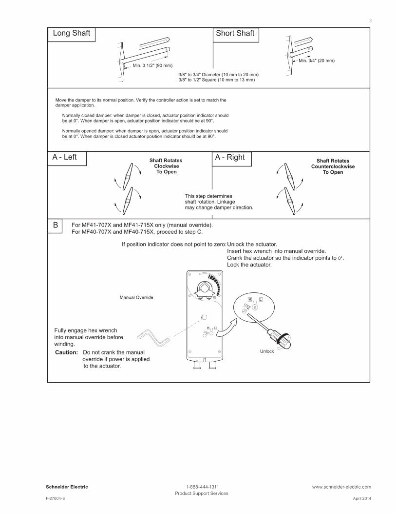
Shaft Rotates ClockwiseTo Open
Shaft RotatesCounterclockwise
To Open
A - Left A - Right
This step determinesshaft rotation. Linkage may change damper direction.
For MF41-707X and MF41-715X only (manual override).
For MF40-707X and MF40-715X, proceed to step C.
R
R LLOCK
R LLOCK
If position indicator does not point to zero:Unlock the actuator.
Insert hex wrench into manual override.
Crank the actuator so the indicator points to 0°.
Lock the actuator.
Caution: Do not crank the manual
override if power is applied
to the actuator.
Manual Override
Unlock
Long Shaft Short Shaft
Min. 3 1/2" (90 mm)
3/8" to 3/4" Diameter (10 mm to 20 mm)3/8" to 1/2" Square (10 mm to 13 mm)
Min. 3/4" (20 mm)
Move the damper to its normal position. Verify the controller action is set to match the damper application.
Normally closed damper: when damper is closed, actuator position indicator should
be at 0°. When damper is open, actuator position indicator should be at 90°.
Normally opened damper: when damper is open, actuator position indicator should
be at 0°. When damper is closed actuator position indicator should be at 90°.
Fully engage hex wrench
into manual override before
winding.

Schneider Electric 1-888-444-1311 www.schneider-electric.com Product Support Services F-27004-6 April 2014
4
C - Left C - Right - Long Shaft
1. Assemble mounting clamp.
2. Assemble retaining clip.
3. Place actuator over shaft.
4. Hand tighten clamp nuts.
R
2010
0-5
3040
L
20
10
0-5
30
40 Correct clamp mounting
position if actuator is
locked with 5° preload.
R
"L" Marker
1
2
L
20
10
0-5
30
40
R
2010
0-5
3040Correct clamp mounting
position if actuator is
in normal spring
return position
For MF40-707X and MF40-715X actuators:
Universalmounting clamp.
Retaining clip.
1
2
3
1
4
2
L
"R" Marker
1
2
L
RL
LOCK
Universalmounting clamp.
Retaining clip.
1
2
2
3
4
RLL
OCK
- Long Shaft
R
1 Universal clamp.
2 Retaining clip.
3 Damper position indicator.
3
L
"R" Marker
1
2
3
1
A
2
4
C - Left - Short Shaft C - Right - Short Shaft
1 Universal clamp.
2 Retaining clip.
3 Damper position indicator.
R"L" Marker 2
3
A
1
2
4
2
3
1
L
A. Assemble damper position indicator.
B. Assemble retaining clip.
1. Position mounting clamp.
2. Assemble retaining clip.
3. Slide actuator over shaft.
4. Hand tighten clamp nuts.
Correct pointer mounting
position if actuator is
in normal spring
return positionR
2010
0-5
3040
L
20
10
0-5
30
40
For MF40-707X and MF40-715X actuators: For MF41-707X and MF41-715X actuators:
R
2010
0-5
3040
L
20
10
0-5
30
40Correct pointer mounting
position if actuator is
locked at 5° preload.
B B

Schneider Electric 1-888-444-1311 www.schneider-electric.com Product Support Services F-27004-6 April 2014
5
E- Left E- RightC
12
R
L Centerline
15
10
R
R
0°
14
5°
9
11
9. Loosen clamp nuts.
10. Check that the shaft is in full zero position.
For MF41-707X and MF41-715X only: 11. Tighten clamp nuts to 8 - 10 ft-lb (11 - 14 Nm).
This completes the installation for MF41-704X
and MF41-715X.
For MF40-707X and MF40-715X only:12. Swing actuator 5° in the direction of travel. Do
not move shaft.
13. Tighten clamp nuts to 8 - 10 ft-lb (11 - 14 Nm).
14. Move bottom of actuator back into position.
15. Pivot bracket back into position.
12
R
CL Centerline
15
14
5°
L
0°
L
9
11
10
D - Left and Right
R
x 17
8
1/2
1/2
Center the Universal Bracket in the Slot
5
6 x 2
5. Center bracket in slot.
6. Drill two holes.
7. Start one screw.
For MF41-707X and MF41-715X actuators, insert and tighten both screws.
8. Swing bracket down (MF40 actuator only).
#8 Sheet MetalScrew1
1
1313

Schneider Electric 1-888-444-1311 www.schneider-electric.com Product Support Services F-27004-6 April 2014
6
F- Left F- Right
x 216 x 216
RL
For MF40-707X and MF40-715X only:16. Tighten bracket screws.
Correct pointer position
after mounting.
Correct pointer position
after mounting.
For MF40-707X and MF40-715X actuators:
For MF41-707X and MF41-715X actuators:
The lock on MF41-707X and MF41-715X will release on first power-up.
R
2010
0-5
3040
L
20
10
0-5
30
40
R
2010
0-5
3040
L
20
10
0-5
30
40

Schneider Electric 1-888-444-1311 www.schneider-electric.com Product Support Services F-27004-6 April 2014
7Rotation Limitation for Mx4x-707x and Mx4x-715x Series
Note:�Limiting the rotation of the actuator also reduces the system throttling range. Be sure to adjust the controller’s throttling range accordingly.
The AM‑689 rotation limiter is used in conjunction with the tab on the universal clamp or the AM‑686 position indicator which comes with the AM‑689. In order to function properly, the clamp or indicator must be mounted correctly.
The AM‑689 rotation limiter controls the rotational output of the Mx4x‑707x, Mx4x‑707x‑502, Mx4x‑715x, and Mx4x‑715x‑502 actuators. It is used in applications where a damper has a designed rotation that is less than 90°, for example with a 45° or 60° rotating damper. It can also be used to provide a minimum damper position which is easily set, or changed, without removing the actuator from the damper.
1. Determine the amount of damper rotation required.
2. Locate the AM‑689 rotation limiter on the actuator so that its edge lines up with the degree graduation on the actuator face which corresponds with the required rotation. See (Figure‑1).
3. Find the appropriate cross hair location through the slot of the rotation limiter. This is the mounting location for the retaining screw.
4. Pierce through the label material to allow easy fastening of the retaining screw.
5. Position the rotation limiter back to the desired position, making sure the locating “teeth” on the rotation limiter are engaged into the locating holes on the actuator.
6. Fasten the rotation limiter to the actuator using the self‑tapping screw provided.
7. Test the damper rotation by applying power and the required control signal. Readjust if necessary.
Rotation Limitation
Screw secured at
these cross hairs.
30
4050
6070
8090
30
4050
6070
8090
Angle of rotation limit
is now set at 40.
3040
50
6070
8090
Figure-1�Securing the AM‑689 Rotation Limiter.
Figure‑1 Securing the AM‑689 Rotation Limiter.
Schneider Electric 1-888-444-1311 www.schneider-electric.com Product Support Services F-27004-6 April 2014
8
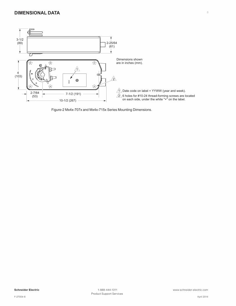
2-25/64(61)
4 (103)
10-1/2 (267)
3-1/2(89)
2-7/64(53)
Dimensions shownare in inches (mm).
7-1/2 (191)
0023
1
2
1 Date code on label = YYWW (year and week).
2 6 holes for #10-24 thread-forming screws are located on each side, under the white "+" on the label.
Figure‑2 Mx4x‑707x and Mx4x‑715x Series Mounting Dimensions.
DIMENSIONAL DATA
Schneider Electric 1-888-444-1311 www.schneider-electric.com Product Support Services F-27004-6 April 2014
9
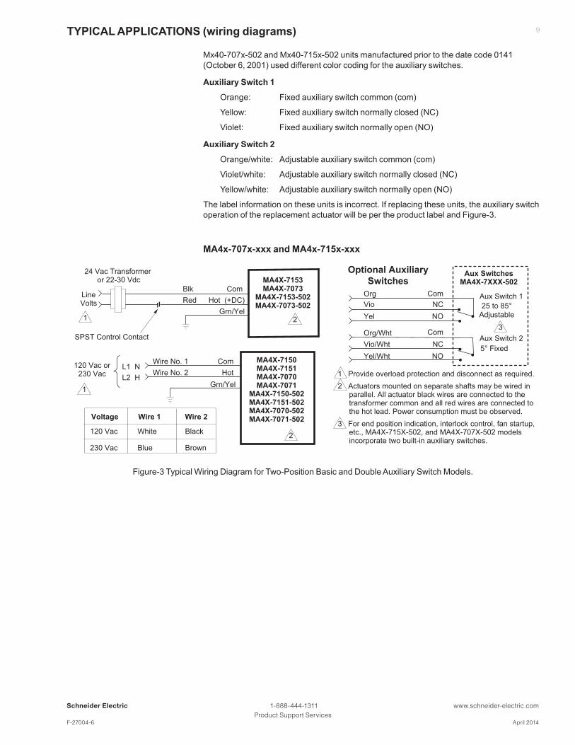
Mx40‑707x‑502 and Mx40‑715x‑502 units manufactured prior to the date code 0141 (October 6, 2001) used different color coding for the auxiliary switches.
Auxiliary Switch 1
Orange: Fixed auxiliary switch common (com)
Yellow: Fixed auxiliary switch normally closed (NC)
Violet: Fixed auxiliary switch normally open (NO)
Auxiliary Switch 2
Orange/white: Adjustable auxiliary switch common (com)
Violet/white: Adjustable auxiliary switch normally closed (NC)
Yellow/white: Adjustable auxiliary switch normally open (NO)
The label information on these units is incorrect. If replacing these units, the auxiliary switch operation of the replacement actuator will be per the product label and Figure‑3.
MA4x-707x-xxx and MA4x-715x-xxx
MA4X-7153MA4X-7073
MA4X-7153-502MA4X-7073-502
21
1 Provide overload protection and disconnect as required.
2 Actuators mounted on separate shafts may be wired in parallel. All actuator black wires are connected to the transformer common and all red wires are connected to the hot lead. Power consumption must be observed.
3 For end position indication, interlock control, fan startup, etc., MA4X-715X-502, and MA4X-707X-502 models incorporate two built-in auxiliary switches.
24 Vac Transformer or 22-30 Vdc
Blk
Red
Com
Hot (+DC)LineVolts
Grn/Yel
SPST Control Contact
2
1
MA4X-7150MA4X-7151MA4X-7070MA4X-7071
MA4X-7150-502MA4X-7151-502MA4X-7070-502MA4X-7071-502
Wire No. 1
Wire No. 2
Com
Hot L1 N
L2 H
120 Vac or230 Vac
Grn/Yel
Org/Wht
Vio/Wht
Yel/Wht
NC
NO
3
Org
Vio
Yel
NC
NO
Com
Com
Aux Switch 1
Aux Switch 2
25 to 85°
Adjustable
5° Fixed
Aux SwitchesMA4X-7XXX-502
Optional Auxiliary
Switches
120 Vac White Black
230 Vac Blue Brown
Voltage Wire 1 Wire 2
Figure-2�Typical Wiring Diagram for Two‑Position Basic and Double Auxiliary Switch Models.
TYPICAL APPLICATIONS (wiring diagrams)
Figure‑3 Typical Wiring Diagram for Two‑Position Basic and Double Auxiliary Switch Models.
Schneider Electric 1-888-444-1311 www.schneider-electric.com Product Support Services F-27004-6 April 2014
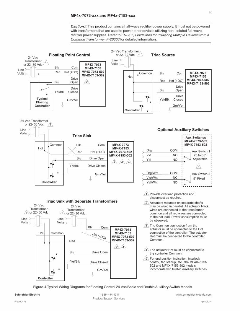
10MF4x-7073-xxx and MF4x-7153-xxx
Caution:�This product contains a half-wave rectifier power supply. It must not be powered with transformers that are used to power other devices utilizing non‑isolated full‑wave rectifier power supplies. Refer to EN‑206, Guidelines for Powering Multiple Devices from a Common Transformer, F‑26363 for detailed information.
MF4X-7073MF4X-7153
MF4X-7073-502MF4X-7153-502
MF4X-7073MF4X-7153
MF4X-7073-502MF4X-7153-502
MF4X-7073MF4X-7153
MF4X-7073-502MF4X-7153-502
TypicalFloating
Controller
2
1
24 VacTransformer
or 22- 30 VdcBlk
Red
Com
Hot (+DC)LineVolts
BluDriveOpen
Yel/Blk
Blk
Grn/Yel
Blu
Yel/Blk
Blk
Grn/Yel
Blu
Yel/Blk
DriveClosed
DriveOpen
DriveClosed
Floating Point Control Triac Source
Red
Com
Hot (+DC)
1
LineVolts
Controller
HotCommon
Triac Sink
Red
Com
Hot (+DC)
1
LineVolts
Controller
2
HotCommon
3Drive Open
Drive Closed
Optional Auxiliary Switches
Blk
Blu
Yel/Blk
Triac Sink with Separate Transformers
Red
Com
Hot (+DC)
Controller
2
Drive Closed
1
LineVolts
Hot Common
Drive Open
1
LineVolts
4
4
5
Grn/Yel
Grn/Yel
1 Provide overload protection and disconnect as required.
2 Actuators mounted on separate shafts may be wired in parallel. All actuator black wires are connected to the transformer common and all red wires are connected to the hot lead. Power consumption must be observed.
3 The Common connection from the actuator must be connected to the Hot connection of the controller. The actuator Hot must be connected to the controller Common.
4 The actuator Hot must be connected to the controller Common.
5 For end position indication, interlock control, fan startup, etc., the MF4X-7073-502 and MF4X-7153-502 models incorporate two built-in auxiliary switches.
MF4X-7073MF4X-7153
MF4X-7073-502MF4X-7153-502
Org/Wht
Vio/Wht
Yel/Wht
NC
COM
NO
Org
Vio
Yel
NC
COM
NO
25 to 85°
Adjustable
5° Fixed
Aux SwitchesMF4X-7073-502MF4X-7153-502
Aux Switch 1
Aux Switch 2
24 Vac Transformeror 22- 30 Vdc
24 VacTransformer
or 22- 30 Vdc
24 VacTransformer
or 22- 30 Vdc
24 Vac Transformeror 22- 30 Vdc
Figure-3�Typical Wiring Diagrams for Floating Control 24 Vac Basic and Double Auxiliary Switch Models.
Figure‑4 Typical Wiring Diagrams for Floating Control 24 Vac Basic and Double Auxiliary Switch Models.

Schneider Electric 1-888-444-1311 www.schneider-electric.com Product Support Services F-27004-6 April 2014
11MS4x-7073-xxx and MS4x-7153-xxx
Caution:�This product contains a half-wave rectifier power supply. It must not be powered with transformers that are used to power other devices utilizing non‑isolated full‑wave rectifier power supplies. Refer to EN‑206, Guidelines for Powering Multiple Devices from a Common Transformer, F‑26363 for detailed information.
1 Provide overload protection and disconnect as required.
2 With four actuators wired to one 500 ohm resistor, a +2% shift of the control signal may be required. (Actuator input impedance is 80 k ohm.)
3 A field-supplied 500 ohm resistor (AM-708) is required between the gray and yellow/black leads to convert the 4 to 20 mAdc control signal to 2 to 10 Vdc.
4 Only connect common to negative (-) leg of control circuits.
5 For end position indication, interlock control, fan startup, etc., MS4X-7XX3-502 models incorporate two built-in auxiliary switches.
6 To reverse actuator rotation, use the reversing switch.
7 Both actuators must be set to operate in the same direction.
COM
5
Org/Wht
Vio/Wht
Yel/Wht
NC
COM
NO
Org
Vio
Yel
NC
NO
25 to 85°
Adjustable
5° Fixed
Aux SwitchesMS4X-7073-502MS4X-7153-502
Aux Switch 1
Aux Switch 2
Optional Auxiliary Switches
To AdditionalActuators
Grn/Yel
Hot (+DC)Red
Blk Com
Com
LineVolts
(-)
(+)Control Signal
4 to 20 mA Yel/Blk
Blu
(-)
(+)
Feedback Signal2 to 10 Vdc
Feedback Signal2 to 10 Vdc
4
6
Gra
L R
AI
AO
MS4X-7073MS4X-7153
MS4X-7073-502MS4X-7153-5023
1
4 to 20 mAdc Proportional Control
Red
Blk Com
Hot (+DC)LineVolts
(-)
(+)
Yel/Blk AI
Red
Blk Com
Hot (+DC)
Yel/Blk AI
Blu AO
6
7
MS4X-7153MS4X-7153-502
L R
6
7
MS4X-7153MS4X-7153-502
L R
ComGra
ComGra
Grn/Yel
Grn/Yel
1
Two Actuators on the Same Damper Shaft
Red
Blk Com
Hot (+DC)LineVolts
(-)
(+)
(-)
(+)
Control Signal2 to 10 Vdc
Control Signal2 to 10 Vdc
Yel/Blk AI
Grn/Yel
ComGra1
6
L R
MS4X-7073MS4X-7153
MS4X-7073-502MS4X-7153-502
2 to 10 Vdc Proportional Control
Blu AO
500 W
24 VacTransformer
or 22- 30 Vdc
24 VacTransformer
or 22- 30 Vdc
24 VacTransformer
or 22- 30 Vdc
2
Figure‑5 Typical Wiring Diagrams for Proportional Control 24 Vac Basic and Double Auxiliary Switch Models.

Schneider Electric 1-888-444-1311 www.schneider-electric.com Product Support Services F-27004-6 April 2014
© 2
014
Sch
neid
er E
lect
ric. A
ll rig
hts
rese
rved
.