mx1-10fep series
TRANSCRIPT

MX1-10FEP Series
User Manual V1.9
Master Series Embedded System
Intel® Coffee Lake Xeon-E / Core-i Processors
Powerful, Versatile, and Rugged & Reliable

PREFACE
Copyright Notice
Copyright © 2016-2019 MiTAC Computing Technology Corporation (MiTAC Group). No part of this
document may be reproduced, copied, translated, or transmitted in any form or by any means,
electronic or mechanical, for any purpose, without the prior written permission of MiTAC Corp., Ltd.
All information and specification provided in this manual are for reference only and remain subject to
change without prior notice.
Disclaimer
We reserve the right to make changes, without notice, to any product, including circuits and/or
software described or contained in this manual in order to improve design and/or performance. We
assume no responsibility or liability for the use of the described product(s) conveys no license or title
under any patent, copyright, or masks work rights to these products, and make no representations or
warranties that these products are free from patent, copyright, or mask work right infringement,
unless otherwise specified. Applications that are described in this manual are for illustration purposes
only. We make no representation or guarantee that such application will be suitable for the specified
use without further testing or modification.
Declaration of Conformity
FCC
This equipment has been tested and found to comply with the limits for a
class "A" digital device, pursuant to part 15 of the FCC rules. These limits
are designed to provide reasonable protection against harmful interference
when the equipment is operated in a commercial environment. This
equipment generates, uses, and can radiate radio frequency energy and, if
not installed and used in accordance with the instruction manual, may
cause harmful interference to radio communications. Operation of this
equipment in a residential area is likely to cause harmful interference in
which case the user will be required to correct the interference at him own
expense.
CE
This equipment is in conformity with the requirement of the following EU
legislations and harmonized standards. Product also complies with the
Council directions.

Safety Information
WARNING! / AVERTISSEMENT!
Always completely disconnect the power cord from your chassis
whenever you work with the hardware. Do not make connections
while the power is on. Sensitive electronic components can be
damaged by sudden power surges. Only experienced electronics
personnel should open the PC chassis.
CAUTION/ATTENTION
Always ground yourself to remove any static charge before touching
the CPU card. Modern electronic devices are very sensitive to static
electric charges. As a safety precaution, use a grounding wrist strap at
all times. Place all electronic components in a static-dissipative
surface or static-shielded bag when they are not in the chassis.
Safety Precautions
For your safety, please carefully read all the safety instructions before using the device. All cautions
and warnings on the equipment should be noted. Keep this user manual for future reference.
*Let service personnel to check the equipment in case any of the following problems appear:
The power cord or plug is damaged.
Liquid has penetrated into the equipment.
The equipment has been exposed to moisture.
The equipment does not work well or you cannot get it to work according to the user manual.
The equipment has been dropped and damaged.
The equipment has obvious signs of breakage on the surface.

Ordering Information
Model Number Description
MX1-10FEP-C246
Fanless Embedded System with Intel® C246 Chipset.
2x260Pin DDR4 SO-DIMM 2666Mhz up to 32GB, 1xHDMI,
1xDisplayPort, 1xDVI-I, 2xGbE LANs, 6xUSB3.0, 2xUSB2.0,
2xCOM, 9~48V DC-in, L6 System w/o AC Adaptor
MX1-10FEP-C246-AC300
Fanless Embedded System with Intel® C246 Chipset.
2x260Pin DDR4 SO-DIMM 2666Mhz up to 32GB, 1xHDMI,
1xDisplayPort, 1xDVI-I, 2xGbE LANs, 6xUSB3.0, 2xUSB2.0,
2xCOM, 9~48V DC-in, L6 System with 300W AC Adaptor, EU
+ US power cords
MX1-10FEP-C246-AC220
Fanless Embedded System with Intel® C246 Chipset.
2x260Pin DDR4 SO-DIMM 2666Mhz up to 32GB, 1xHDMI,
1xDisplayPort, 1xDVI-I, 2xGbE LANs, 6xUSB3.0, 2xUSB2.0,
2xCOM, 9~48V DC-in, L6 System with 220W AC Adaptor, EU
+ US power cords
MX1-10FEP-D-C246-FL
Fanless Embedded System with Intel® C246 Chipset.
2x260Pin DDR4 SO-DIMM 2666Mhz up to 32GB, 1xHDMI,
1xDisplayPort, 1xDVI-I, 2xGbE LANs, 6xUSB3.0, 2xUSB2.0,
2xCOM, PCIe X1+X16, 9~48V DC-in, L6 System w/o AC
Adaptor
MX1-10FEP-D-C246-FL-AC300
Fanless Embedded System with Intel® C246 Chipset.
2x260Pin DDR4 SO-DIMM 2666Mhz up to 32GB, 1xHDMI,
1xDisplayPort, 1xDVI-I, 2xGbE LANs, 6xUSB3.0, 2xUSB2.0,
2xCOM, PCIe X1+X16, 9~48V DC-in, L6 System with 300W
AC Adaptor, EU + US power cords
MX1-10FEP-D-C246-IF-AC300
Embedded System with Intel® C246 Chipset.
2x260Pin DDR4 SO-DIMM 2666Mhz up to 32GB, 1xHDMI,
1xDisplayPort, 1xDVI-I, 2xGbE LANs, 6xUSB3.0, 2xUSB2.0,
2xCOM, PCIe X1+X16, 9~48V DC-in, L6 System with 300W
AC Adaptor, EU + US power cords, and 2x pre-installed
Internal System Fan
MX1-10FEP-D-C246-IEF-AC300
Embedded System with Intel® C246 Chipset.
2x260Pin DDR4 SO-DIMM 2666Mhz up to 32GB, 1xHDMI,
1xDisplayPort, 1xDVI-I, 2xGbE LANs, 6xUSB3.0, 2xUSB2.0,
2xCOM, PCIe X1+X16, 9~48V DC-in, L6 System with 300W
AC Adaptor, EU + US power cords, and 2x pre-installed
Internal System Fan + 1xExternal System Fan in AK box

Packing List
Item Description Q’ty
1 MX1-10FEP or MX1-10FEP-D Embedded System 1
2 CPU Cooler (passive) 1
3 Quick Installation Guide (1 page) 2
4 Wall Mount Brackets (2 pcs in 1 set) 1
5 Driver CD 1
6 Screw Pack (For HDD, SATA cable, and Wall Mount Bracket) 1
7 3-pin Terminal Block Power Connector (For DC Power Input) 1
8 4-pin Terminal Block Power Connector (For PWM fan) 1
9 2-pin Terminal Block Power Connector (For Remote Power Control) 2
10 DVI to VGA converter 1
11 SATA Y cable 1

Optional Xpansion Modules and Accessories
Model Number Description
MS-48CDN-DT10
Expansion Module with 4 x RS232 / 422 / 485, 8-bit Isolated DIDO
(4 x DI, 4 x DO)
MS-04LAN-R10
Expansion Module with 4 x Intel i210-IT Giga LAN, RJ45 Port
MS-04LAN-M10
Expansion Module with 4 x Intel i210-IT Giga LAN, M12 Port
MS-04POE-R10
Expansion Module with 4 x PoE+, Intel i210-IT Giga LAN, RJ45
Port
MS-04POE-M10
Expansion Module with 4 x PoE+, Intel i210-IT Giga LAN, M12
Port
ME-02POE-R10
Expansion Module with 2 x PoE+, Intel i210-IT Giga LAN, RJ45
Port
MS-01IGN-S10
Vehicle Power Ignition Card, 12V/24V and Power ON/OFF Timing
Selectable

MX1D-02INFAN-GFX Internal 4020 FAN Kit for GFX Card
(for MX1-10FEP-D Model)
MX1D-02INFAN-TP4 Internal 4028 FAN with FAN duct Kit for T4/P4 Card
(for MX1-10FEP-D Model)
MX1-01EXFAN External FAN Kit
(for both MX1-10FEP and MX1-10FEP-D Models)
MP-116RCN-P10
MP-116RCN-P10_(PCIEX1 + PCIEX16) Riser Card w/ Single
Packing
(for MX1-10FEP-D Model)
*This is option. MX1-10FEP-D BOM already has one default
PCIeX16+PCIeX1 riser card
MP-088RCN-P10
MP-088RCN-P10_(PCIEX8+PCIEX8) Riser Card w/ Single
Packing
(for MX1-10FEP-D Model)
*This is option. BOM already has one default PCIeX16+PCIeX1
riser card
MPE-300W24-3TUE AC/DC 24V/12.5A, 300W 3PIN Terminal Block Power Adaptor
with EU+US power cords
MPE-220W24-3TUE AC/DC 24V/9.2A, 220W 3PIN Terminal Block Power Adaptor with
EU+US power cords
MPC-180W12-4DUE AC/DC 12V/15A, 180W DIN4PIN Power Adaptor with internal
power cable, and EU+US power cords
(2nd AC adaptor for MX1-10FEP-D Model with 120W GFX card
power solution)

CONTENTS
PREFACE ............................................................................................................................................... 1
CHAPTER 1: INTRODUCTION .............................................................................................................. 10
1.1 Overview .............................................................................................................................. 10
1.2 Product Features .................................................................................................................. 10
1.3 MX1-10FEP & MX1-10FEP-D CPU Options ........................................................................... 11
1.4 Hardware Specification ........................................................................................................ 12
1.5 Mechanical Specification ..................................................................................................... 16
1.6 System I/O Placement .......................................................................................................... 18
CHAPTER 2: DIP SWITCH SETTING AND PIN DEFINITION ................................................................... 22
2.1 Jumper and Internal Connector Overall Placement ............................................................. 22
2.2 DIP Switch Setting ................................................................................................................ 23
2.3 Internal Connector Pin Definition ........................................................................................ 24
2.4 External Connector Pin Definition ........................................................................................ 28
2.5 Xpansion Module MS-48CDN-DT10 ..................................................................................... 31
2.6 Xpansion Module MS-04LAN-M10 ...................................................................................... 35
2.7 Xpansion Module MS-01IGN-S10 ......................................................................................... 36
CHAPTER 3: SYSTEM SETUP................................................................................................................ 38
3.1 1st 2.5” SATA HDD/SSD Installation ...................................................................................... 38
3.2 2nd and 3rd 2.5” SATA HDD/SSD Installation ......................................................................... 40
3.3 CPU/CPU Heatsink/DRAM Installation ................................................................................. 42
3.4 RTC Battery Maintenance .................................................................................................... 45
3.5 External Fan (Optional) Installation Guide ........................................................................... 46
CHAPTER 4: BIOS SETUP ..................................................................................................................... 48
4.1 Main Page ............................................................................................................................. 48
4.2 Advance Page ....................................................................................................................... 50
4.3 Security Page ........................................................................................................................ 61
4.4 Boot Page ............................................................................................................................. 67
4.5 Save & Exit Page ................................................................................................................... 69
INTRODUCTION
This chapter provides the MX1-10FEP Embedded
System product overview, including features,
hardware and mechanical specifications. 1

CHAPTER 1: INTRODUCTION
This chapter provides the MX1-10FEP Embedded System product overview, including features,
hardware, mechanical specifications, and I/O placement.
1.1 Overview
MiTAC’s MX1-10FEP embedded system is the next generation embedded system with Intel® Coffee
Lake C246 workstation chipset which can support Xeon and Core-i LGA1151 socket type processor.
The excellent performance, powerful processor, OCP/OVP power protection, and expandable
design provide the solution for every complicated task and most types of application.
1.2 Product Features
MX1-10FEP Embedded System offers the following features:
8th & 9th Generation Intel® Xeon-E, Core™ i7 / i5 / i3 Processors
Triple Display with HDMI, DisplayPort, and DVI-I Interface
Fan-less chassis and Expandable module design
Support COM/DIO/LAN/PoE via Xpansion Modules
Support Power Ignition for Vehicle Application via Xpansion Module
9-48V Wide Power Voltage
-40 to 70 Celsius degrees Wide Temperature with 35W CPU
-40 to 50 Celsius degrees Wide Temperature with 51-65W CPU
-40 to 40 Celsius degrees Wide Temperature with 71-80W CPU

1.3 MX1-10FEP & MX1-10FEP-D CPU Options
Processor Name Cores Threads TDP
Intel® Xeon® E Processor
Intel® Xeon® E-2226GE Processor, 12M Cache, up to 4.60 GHz 6 6 80W
Intel® Xeon® E-2176G Processor, 12M Cache, up to 4.70 GHz 6 12 80W
Intel® Xeon® E-2124G Processor, 8M Cache, up to 4.50 GHz 4 4 71W
Intel® Coffee Lake Refresh 9th Generation
Intel® Core™ i7-9700TE Processor, 12M Cache, up to 3.80 GHz 8 8 35W
Intel® Core™ i5-9500E Processor, 9M Cache, up to 4.20 GHz 6 6 65W
Intel® Core™ i5-9500TE Processor, 9M Cache, up to 3.60 GHz 6 6 35W
Intel® Core™ i3-9100E Processor, 6M Cache, up to 3.70 GHz 4 4 65W
Intel® Core™ i3-9100TE Processor, 6M Cache, up to 3.20 GHz 4 4 35W
Intel® Coffee Lake 8th Generation
Intel® Core™ i7-8700 Processor, 12M Cache, up to 4.60 GHz 6 12 65W
Intel® Core™ i7-8700T Processor, 12M Cache, up to 4.00 GHz 6 12 35W
Intel® Core™ i5-8500 Processor, 9M Cache, up to 4.10 GHz 6 6 65W
Intel® Core™ i5-8500T Processor, 9M Cache, up to 3.50 GHz 6 6 35W
Intel® Core™ i3-8100 Processor, 6M Cache, 3.60 GHz 4 4 65W
Intel® Core™ i3-8100T Processor, 6M Cache, 3.10 GHz 4 4 35W

1.4 Hardware Specification
SYSTEM
CPU 8th Gen Intel® Coffee Lake Xeon-E / Core-i LGA1151 Socket Processor
TDP Max. 80W
Chipset Intel® C246
System Memory DDR4 2666MHz, 2 x 260-pin SO-DIMM, Max. 32GB
(Xeon: ECC; Core-i: Non-ECC)
Graphics Intel® HD Graphics
Display Interface HDMI, DisplayPort, DVI-I
Storage Slot 3 x 2.5 HDD / SSD (1 w/ Removable HDD Bay; 2 w/ Internal HDD Bracket, 1st SATA
cable as Default, 2nd SATA cable as Option)
2 x mSATA
Ethernet Intel® I219-LM Giga LAN + I210-IT Giga LAN
Audio Realtek® ALC662
I/O Chipset Nuvoton NCT6116D
TPM Nuvoton NPCT750AAAYX
Expansion Slot Storage: M.2 2242 / 2260 / 2280 M key (PCIe X4 / SATAIII)
Storage/LTE/Wireless: 2 x Mini PCIe Full / Half size (USB2.0 / PCIe X1 / SATAIII), w/
SIM Card Holder
Wireless: M.2 2230 E key (PCIe X1 / USB2.0)
a. PCIe 3.0 x16 (MX1-10FEP)
b. PCIe 3.0 x16 + PCIe 3.0 x1 (MX1-10FEP-D Default)
PCIe 3.0 x8 + PCIe 3.0 x8 (MX1-10FEP-D Option)
Indicator Power LED, HDD LED, DIO LED, LAN1 & 2 ACT / SPEED
FRONT I/O 2 x USB 3.0
1 x HDMI 1.4
2 x SIM Card Slot w/ Cover
1 x 2.5" SATAIII HDD / SSD Bay
REAR I/O 4 x USB 3.1 Gen 2 (Gbps), 2 x USB 2.0, 2 x RJ-45 , 1 x DisplayPort 1.2, 1 x DVI-I, 1
x PS/2
2 x RS232 / 422 / 485 (Support Power 5V / 12V), 1 x Mic-in, 1 x Line-out
1 x 2-pin Terminal Block Remote Power on / off
1 x 2-pin Terminal Block Remote Power reset
1 x 4-pin Terminal Block External Fan Connector
1 x 3-pin Terminal Block Power Input
4 x SMA Antenna (Optional for WiFi/LTE function)
Watchdog Timer 1~255 Steps by Software Program

POWER REQUIREMENT
Power Input 9~48V Wide Rage DC Input w/ Terminal Block Connectivity
*For DC source in directly, the maximum operating ambient temperature is 70℃.
For using with External AC adaptor model: EA13001N-240 (for 12.5A rating), the
maximum ambient operating temperature is 40℃ if the system will be for using with
external AC adaptor model: EA13001N-240.
MECHANICAL
Thermal Design a. MX1-10FEP: Fanless
b. MX1-10FEP-D: Fanless or with 2 x 40m x 20cm Internal System Fan
(External System Fan Kit as Option in Accessories)
Mounting Wall mount
Dimension a. MX1-10FEP: 10.6” x 9.7” x 4.3” (268 mm x 246 mm x 108 mm)
b. MX1-10FEP-D: 10.6” x 9.7” x 5” (268 mm x 246 mm x 128 mm)
Material Top cover: Aluminum Alloy , Bezel and chassis: Steel
ENVIRONMENTAL
Operating
Temperature
a. MX1-10FEP & MX1-10FEP-D Fanless Design:
35W TDP Processor: -40°C to 70°C
51~65W TDP Processor: -40°C to 50°C
71~80W TDP Processor: -40°C to 40°C
(with 0.7m/s Air Flow and Wide Temperature Memory/Storage)
b. MX1-10FEP-D Fan Design, for max. 120W GFX Card thermal design, add
Internal 40x20 System Fan x 2:
35W TDP Processor: -20°C to 50°C
51~65W TDP Processor: -20°C to 45°C
71~80W TDP Processor: -20°C to 40°C
(with 0.7m/s Air Flow and Wide Temperature Memory/Storage)
c. MX1-10FEP-D Fan Design, for max. 120W GFX Card thermal design, add
Internal 40x20 System Fan x 2 & External System Fan:
35W TDP Processor: -20°C to 55°C
51~65W TDP Processor: -20°C to 50°C
71~80W TDP Processor: -20°C to 45°C
(with 0.7m/s Air Flow and Wide Temperature Memory/Storage)
d. MX1-10FEP-D Fan Design, for Nvidia 70W T4 and 75W P4 Card, add
Internal 40x28 System Fan x 2:
35~80W TDP Processor: -20°C to 50°C
(with 0.7m/s Air Flow and Wide Temperature Memory/Storage)
Operating Humidity 10%~90% R/H (Non-condensing)
Vibration Resistance Operating, 5 Grms, 5-500 Hz, 3 Axes
(w/ SSD, according to IEC60068-2-64; w/o GFX Card)
Shock Resistance Operating, 50 Grms, Half-sine 11 ms Duration

(w/ SSD, according to IEC60068-2-27; w/o GFX Card)
Certification EMC: CE & FCC
Safety: compliant with LVD, EN62368-1
EN50155/EN50121/E-mark
OS
OS Support Windows® 10 64-bit, Linux (support by request)
*Notes1: Installation in Restricted Access Location (RAL)
A restricted access location is a designated area within an incident area
(High or Low temperature environment)
With authorized people can enter for a period of time and for a specific
purpose.
1. Access can only be gained by service people or by users who have been
instructed about the reasons for the Restrictions applied to the location
and about any precautions that shall be taken.
2. Access is through the use of a tool or lock and key, or other means of
security, and is controlled by the authority Responsible for the location.
*Notes2: Please make sure that the power consumption is in the spec of the
power supply output capability from AC adaptor (220W or 300W). Please
choose the suitable AC adaptor for your application.
AC/DC 24V/12.5A, 300W 3PIN Terminal Block Power Adaptor
AC/DC 24V/9.16A, 220W 3PIN Terminal Block Power Adaptor
*Note3: The safety ambient operating temperature is 40 degree C if the
external AC adapter model: EA12501J or EA13001N will be placed in the
same high temperature area with the embedded system.
*Note4: In the PXE application, please install i219-LM driver in OS image in
advance before installing OS via PXE server.
*Note5: CAUTION - Lithium battery is included in this embedded system.
Please do not puncture, mutilate, or dispose of battery in fire. There will be
danger of explosion if battery is incorrectly replaced. Replace only with the
same or equivalent type recommended by manufacturer. Dispose of used
battery according to manufacturer instructions and in accordance with your
local regulations.

*Note6: The following configurations in ultimate use might cause system
shut down unexpectedly.
- 12 x LANs or 10 x PoE LANs with some NVMe SSD models (Please check the available list
with our sales contact window)
- 12 x LANs or 10 x PoE LANs with mPCIe or M.2 Wifi Card (Not include CNVi Wifi Card.
Please check the available list with our sales contact window)
*Note7: Please read the BIOS release note before re-flashing BIOS. If the
BIOS notes mention the BIOS will be loaded default after re-flashing BIOS,
please check the BIOS setting again before boot up. For example,
inconsistent RAID setting might cause system boot up issue.
*Note8: When MX1-10FEP-D is installed with PCIe GFX card, the BIOS setup
menu will only have display output via external graphic card.
*Note9: When MX1-10FEP-D is installed with dual layer PCIe GFX card, it can
only be installed with 1 internal HDD/SSD (not include removable HDD/SSD)
instead of 2 due to mechanical limitation. The SATA cable connector needs
to insert to the SATA connector beside the 2*40x40x20mm internal system
fan. The cable clip might also need to be removed due to mechanical
concern with GFX card.
*Note10: When MX1-10FEP-D is installed with NVIDIA T4 or P4 AI card,
2*40x40x28mm internal system fan, and fan duct, it can only be installed
with 1 internal HDD/SSD (not include removable HDD/SSD) instead of 2 in
avoid of fan duct interference. The SATA cable connector needs to insert to
the internal SATA connector.

1.5 Mechanical Specification
MX1-10FEP Mechanical Dimension: 268 mm x 246 mm x 108 mm
PCI Express x16 Slot Maximum Card Dimension:
111.15 x 200 x 18.7mm with mPCIe PoE Module
111.15 x 230 x 18.7mm w/o mPCIe PoE Module

MX1-10FEP-D Mechanical Dimension: 268 mm x 246 mm x 128 mm
PCI Express x16 Slot Maximum Card Dimension:
145 x 221 x 43mm w/o mPCIe PoE Module
PCI Express X16 + X1 Dual Slot (Default)
PCI Express X8 + X8 Dual Slot (Optional)
AI / Graphic Card Support List
NVIDIA Quadro P400 (30W)
NVIDIA Quadro P620 (40W)
NVIDIA Quadro P2000 (75W)
Nvidia Tesla T4 / P4 (75W)
Aetina GTX1050 N1050-J9FX, 2GB (75W)
Leadtek WinFast GTX1650, 4GB (75W)
Leadtek WinFast GTX1660 HURRICANE, 6GB (120W) with 2nd 12V, 180W AC Adaptor
Leadtek WinFast GTX1660 Ti HURRICANE, 6GB (120W) with 2nd 12V, 180W AC Adaptor
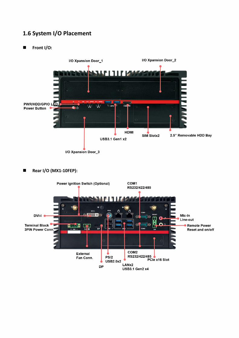
1.6 System I/O Placement
Front I/O:
Rear I/O (MX1-10FEP):

Rear I/O (MX1-10FE-D):
*Notes: The recommended dimension of USB cable connector or device for USB2.0 ports is 9mm height x 19mm width
when all the other I/O ports are occupied. It still needs to depend on the DisplayPort connector and other devices’
dimension to aviod the interference.

Xpansion Module (Optional) Configuration Table
*Notes: ME-02POE-R10 cannot be installed in door#3 of MX1-10FEP-D-C246-IF and MX1-10FEP-D-C246-IEF models due to
interference with internal system fan at the same location.

DIP SWITCH SETTING AND PIN DEFINITION
This chapter provides information about how to set up the
dip switch and use internal I/Os of MX1-10FEP Embedded
System hardware. 2

CHAPTER 2: DIP SWITCH SETTING AND PIN DEFINITION
This chapter provides information about how to set up the dip switch, and use internal I/Os of
MX1-10FEP Embedded System hardware.
2.1 Jumper and Internal Connector Overall Placement
A 1st Board to Board connector B DIMM sockets C 2nd Board to Board connector D Mini PCIe slot 2 E CPU socket F DIP Switch for Power COM G AT/ATX mode switch H M.2 KEY E connector I Board to Board connector for power Ignition J 5V power header K 5V power header L 12V power header for POE module of Mini PCIe M 12V power header for POE module of Mini PCIe N 2nd SATA Signal Header O 2nd SATA Power Header P FAN Header

Q 1ST SATA Connector R Coin Battery Connector S M.2 KEY M T PCIE X16 U Clear CMOS switch V Mini PCIe Slot 1 W PCIE X1 X 3rd SATA Signal Header Y 3rd SATA Power Header
2.2 DIP Switch Setting
Location #G
Pin Signal
UP ATX mode
Down AT mode
Location #F
Switch setting Mode 1 2
1-2 COM 1
RI ON ON
5V ON OFF
12V OFF ON
Switch setting Mode
3-4 COM 2
RI ON ON
5V ON OFF
12V OFF ON

2.3 Internal Connector Pin Definition
Location #Q – 1st SATA Connector
Pin Signal Name
P1 VCC3
P2 VCC3
P3 VCC3
P4 GND
P5 GND
P6 GND
P7 VCC
P8 VCC
P9 VCC
P10 GND
P11 RES
P12 GND
P13 +12V
P14 +12V
P15 +12V
S1 GND
S2 SATAHDR_TXP0_C
S3 SATAHDR_TXN0_C
S4 GND
S5 SATAHDR_RXN0_C
S6 SATAHDR_RXP0_C
S7 GND
Location #O/#Y – 2nd and 3rd SATA Power Header

Pin Signal Name
1 VCC3
2 GND
3 VCC
4 VCC
5 GND
6 +12V
7 +12V
Location #N/#X – 2nd and 3rd SATA Signal Header
Pin Signal Name Description
1 GND Ground
2 SATAHDR_TXP_C SATA DATA Transmit(positive)
3 SATAHDR_TXN_C SATA DATA Transmit(negative)
4 GND Ground
5 SATAHDR_RXN_C SATA DATA Receive(negative)
6 SATAHDR_RXP_C SATA DATA Receive(positive)
7 GND Ground
8 G1 GND
9 G2 GND

Location #P – Fan Header
Pin Signal
1 Ground
2 +12V
3 CPU_FAN_TACH
4 CPU_FAN_CTRL
Location #H – M.2 Key E Slot

Location #S – M.2 Key M Slot

Location #L/#M – 12V Power Header for PoE Xpansion
Pin Signal
1 Ground
2 +12V
3 +12V
4 GND
Location #J/#K – 5V Power Header for Reservation
Pin Signal
1 +5V
2 Ground
2.4 External Connector Pin Definition
3-pin terminal block for DC Input
Pin Signal
1 DC IN +9~48VIN
2 Ignition (IGN)
3 GND

4-pin Terminal Block for PWM Fan
Pin Signal
1 Ground
2 +12V
3 System_FAN_TACH
4 SYSTEM_FAN_CTRL
2-pin Terminal Block for Remote Power ON/OFF and Reset
Pin Signal
1 Ground
2 EXT Reset
3 Ground
4 EXT_PWRBT_ON/OFF

COM#1 / COM#2

2.5 Xpansion Module MS-48CDN-DT10
This Module MS-48CDN-DT10 consists of two parts, one is Serial COM, and the other is Digital IO
function.
Please see the guideline about how to set up this Module correctly.
COM Port Setting a. Location
MS-48CDN-DT10 has total 4 x COM port. These COM ports can be set to be
RS232/RS422/RS485 or powered RS232. There are 2 kinds of Xpansion COM driver.
One is standard non-fixed COM port order driver, and the other one is fixed COM order driver.
If what you install is fixed COM port order driver, the position will be as follows.
1st MS-48CDN-DT10 (Left Xpansion Door) 2nd MS-48CDN-DT10 (Right Xpansion Door)

b. Dip Switch Function
(1) COM PID selection switch
Set A-B; COM PID 0x1414 is determined by UART controller (default).
Set B-C; COM PID 0x1415 is determined by EEPROM (setting for 2nd MS-48CDN-DT10).
(2) Powered COM enable switch
(3) Powered COM power source selection switch

(4) COM Mode setting switch
(5) COM Port Pinout

Digital IO Port MS-48CDN-DT10 has total 8-bit GPIO, the position is as follows.
Left DIO Xpansion Right DIO Xpansion
PIN HW Left DIO
Order
Right DIO
Order
Description
PIN1 DI_1 21 11 Digital Input 1
PIN2 DO_1 22 12 Digital Output 1
PIN3 DI_2 23 13 Digital Input 2
PIN4 DO_2 24 14 Digital Output 2
PIN5 DI_3 25 15 Digital Input 3
PIN6 DO_3 26 16 Digital Output 3
PIN7 DI_4 27 17 Digital Input 4
PIN8 DO_4 28 18 Digital Output 4
PIN9 VCC - - VCC
PIN10 GND - - Ground

2.6 Xpansion Module MS-04LAN-M10
This Module is a Giga LAN module, which supports four M12 type interfaces.
Combined with MS-01PON-S10 to support PoE (typeA).
M12 Code A LAN Module Pin definitions

2.7 Xpansion Module MS-01IGN-S10
This Module MS-01IGN-S10 can detect vehicle ignition status and control the on/off delay time
setting. This document is used to guide how to set up this power ignition module correctly.
a. Location
b. Function Emergency reset button
This button is for engineering use only. The host will be reset when this button is pressed.
Input power selection switch
Common car power supplies are DC 12V or 24V. Please set it according to your
environment.
c. Delay Power On/Off Setting Switch
This feature detects the ignition signal status and allows users to control the on/off delay
time setting through DIP switch.

SYSTEM SETUP
This chapter provides information about how to set up the
MX1-10FEP Embedded System hardware installation. 3

CHAPTER 3: SYSTEM SETUP
This chapter provides information about how to set up the MX1-10FEP Embedded System
hardware installation.
Warning: The edge of MX1-10FEP aluminum extrusion fins is a little bit sharp.
Please be careful when you move the unit, do the installation, and operate the
embedded system!
3.1 1st 2.5” SATA HDD/SSD Installation
Please follow the instructions to install SATA HDD as below.
- Remove the door from front bezel
*Notes: After loosen the four screws from the expansion door, please lift the cover by fingernail slightly and be careful to
take the door out of the front bezel.
- Pull the HDD tray out from main chassis

- Fasten the screws to assemble the HDD/SSD to the bracket
- Insert the HDD/SSD tray back to main chassis and fasten the screws on the door
*Notes: Please keep the unit in horizontally. It will make it easierly to insert the HDD tray back to machine.
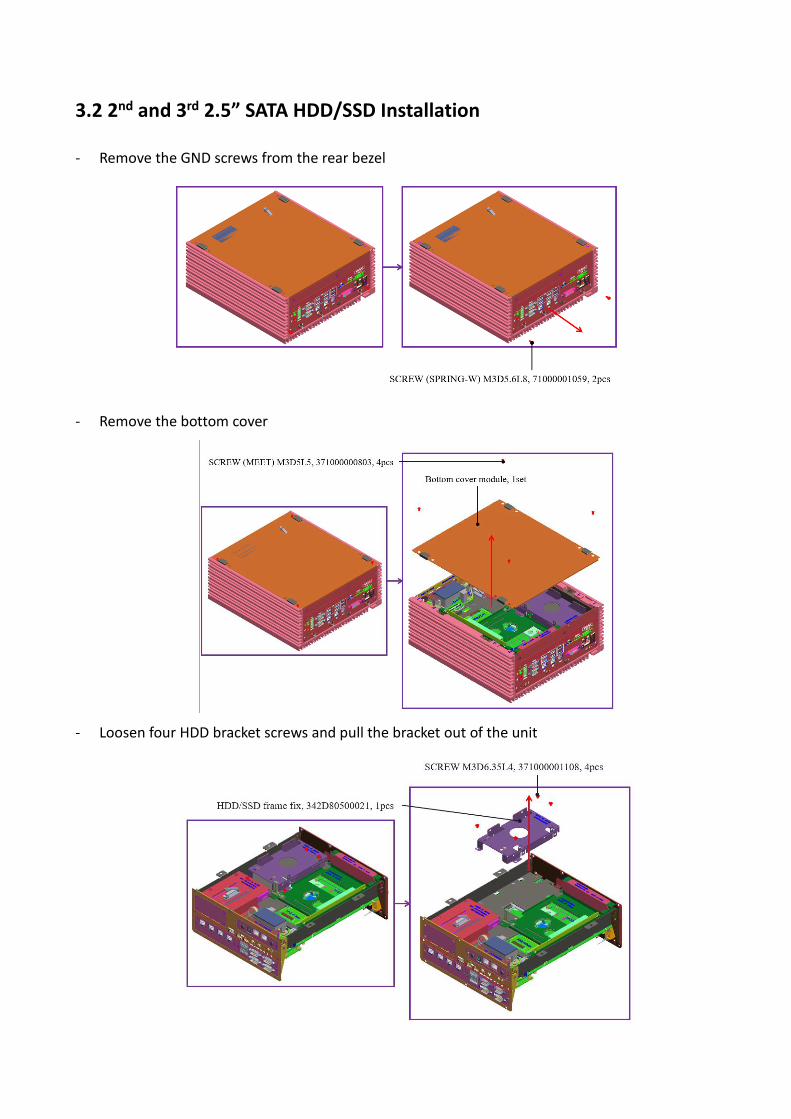
3.2 2nd and 3rd 2.5” SATA HDD/SSD Installation
- Remove the GND screws from the rear bezel
- Remove the bottom cover
- Loosen four HDD bracket screws and pull the bracket out of the unit

- Fasten 2nd and 3rd HDD/SSD to the bracket as following concept drawing
- Fasten four bracket screws to the main unit
- Follow the drawing to do the SATA cable routing

3.3 CPU/CPU Heatsink/DRAM Installation
- Remove the GND screws from the rear bezel
- Remove the bottom cover
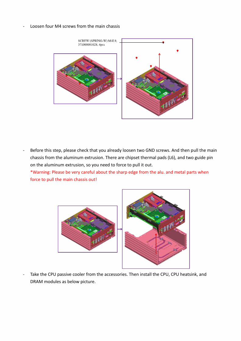
- Loosen four M4 screws from the main chassis
- Before this step, please check that you already loosen two GND screws. And then pull the main
chassis from the aluminum extrusion. There are chipset thermal pads (L6), and two guide pin
on the aluminum extrusion, so you need to force to pull it out.
*Warning: Please be very careful about the sharp edge from the alu. and metal parts when
force to pull the main chassis out!
- Take the CPU passive cooler from the accessories. Then install the CPU, CPU heatsink, and
DRAM modules as below picture.


3.4 RTC Battery Maintenance
- Preparation for disassembly:
Flathead Screwdriver
(The battery holder is designed for great
vibration resistant and harsh environment
use, so it needs to use a tool to disassemble
the coin battery)
- Insert flathead screwdriver to the gap of one side of RTC battery vertically.
- Rotate the screwdriver at around 45 degrees to loosen the coin battery

3.5 External Fan (Optional) Installation Guide
- Twist the thumbscrews counterclockwise on external fan
- Align the edge of external fan bracket as green arrows, and align the metal latch as red arrow
direction. Then insert the fan to the center of housing
- Tighten thumbscrews to fix the external fan, and connect the 4-pin cable to the PWM fan
connector from rear I/O
*Notes: Please don’t do any operation when the system is booted up. When the external system fan bracket is not
installed properly and with system power on, operator might get unexpected hurt from the operation.

BIOS SETUP
This chapter provides information about how to set up BIOS
and use BIOS menu items to adjust basic function settings. 4

CHAPTER 4: BIOS SETUP
This chapter provides information about how to set up BIOS and use BIOS menu items to adjust
basic function settings.
4.1 Main Page
Field Name BIOS Vender
Default Value AMI Megatrends
Comment This field is not selectable. There is no help text associated with it.
Field Name BIOS Version
Default Value Display the version of the BIOS
Comment This field is not selectable. There is no help text associated with it.
Field Name Build Date
Default Value Display build date of the BIOS
Comment This field is not selectable. There is no help text associated with it.
Field Name ME (TXE) FW Version
Default Value ME Firmware Version.
Comment This field is not selectable. There is no help text associated with it.
Field Name Processor Information
Value Display the installed CPU brand.
Comment This field is not selectable. There is no help text associated with it.

Field Name Total Memory
Value Display the installed memory size.
Comment This field is not selectable. There is no help text associated with it.
Field Name Memory Frequency
Value Display the installed memory frequency.
Comment This field is not selectable. There is no help text associated with it.
Field Name SATA#1 / SATA#2 / SATA#3 / M.2#4 / mSATA#5 / mSATA#6
Value Display the installed SATA port device.
Comment This field is not selectable. There is no help text associated with it.
Field Name System Date
Default Value [Www mm/dd/yyyy]
Possible Value Www : Mon/Tue/Wed/Thu/Fri/Sat/Sun mm : 1-12 dd : 1-31 yyyy : 1998-9999
Help Set the Date. Use Tab to switch between Date elements.
Field Name System Time
Default Value [hh :mm :ss]
Possible Value hh : 0-23 mm : 0-59 ss : 0-59
Help Set the Time. Use Tab to switch between Time elements.

4.2 Advance Page
Advanced Description
► Onboard Devices Onboard Device Configuration
► CPU Configuration CPU Configuration Parameters
► Trusted Computing Trusted Computing Settings
► WatchDog WatchDog Configuration
► Super IO Configuration System Super IO Chip Parameters.
► NCT6116D HW Monitor Monitor hardware status
► S5 RTC Wake Setting Enable System to wake from S5 using RTC alarm
► Network Stack Configuration Network Stack Settings
► NVMe Configuration NVMe Device Options Settings

4.2.1 Onboard Device
► Onboard Devices Value Onboard Device Configuration
Turbo Mode
Disabled / [Enabled]
Enable/Disable processor Turbo Mode (requires Intel
Speed Step or Intel Speed Shift to be available and
enabled).
State After G3 S0 State / [S5 State]
Specify what state to go to when power is re-applied after
a power failure (G3 state).
DVMT Pre-Allocated
[64M] / 32M/F7 / 36M /
40M / 44M / 48M / 52M /
56M / 60M
Select DVMT 5.0 Pre-Allocated(Fixed) Graphics Memory
size used by the Internal Graphics Device.
DVMT Total Gfx Mem 128MB / [256MB] /Max
Select DVMT5.0 Total Graphic Menory size used by the
Internal Graphics Device.
SATA Mode Selection [AHCI] / Intel RST
Premium With Intel
Optane System
Acceleration
Determines how SATA controller(s) operate.
Wake on LAN Enable [Enabled] / Disabled Enable/Disable integrated LAN to wake the system.

HD Audio
Disabled / [Enabled]
Control Detection of the HD-Audio device.
Disable = HAD will be unconditionally disabled
Enabled = HAD will be unconditionally enabled.
4.2.2 CPU Configuration
► CPU Configuration Value CPU Configuration Parameters
CPU Configuration
Type Intel® xxxx® xxxxxx xxxxxxx
ID 0xXXXX
Speed XXXX MHz
L1 Data Cache EX. 32KB x 2
L1 Instruction Cache EX. 32KB x 2
L2 Cache EX. 256KB x 2
L3 Cache EX. 3MB
L4 Cache
VMX Supported
SMX/TXT Supported

Intel Trusted Execution
Technology
[Enabled] / Disabled
Enables utilization of additional
hardware capabilities provided by
Intel® Trusted Execution Technology.
Changes require a full power cycle to
take effect.
4.2.3 Trusted Computing
► Trusted Computing Value Trusted Computing Settings
TPM20 Device Found
Firmware Version: x.x
Vendor: xxxxxx
Security Device Support [Disabled] / Enabled
Enables or Disables BIOS support for
security device. O.S. will not show
Security Device. TCG EFI protocol and
INT1A interface will not be available.
Pending operation [None] / TPM Clear Schedule an Operation for the Security
Device. NOTE: Your Computer will

reboot during restart in order to change
State of Security Device.
4.2.4 WatchDog
► WatchDog Value WatchDog Configuration
WatchDog [Disabled] / Enabled Enables or Ddisables WatchDog function.
4.2.5 Super IO Configuration

► Super IO Configuration Value System Super IO Chip Parameters.
Super IO Configuration
Super IO Chip NCT6116D
► Serial Port 1 Configuration Value Set Parameters of Serial Port 1
(COMA)

Serial Port 1 Configuration
Serial Port Disabled / [Enabled] Enable or Disable Serial Port (COM)
Device Settings IO=3F8h; IRQ=4
Change settings [Auto] / IO=3F8h; IRQ=4
/ IO=3F8h; IRQ=3, 4, 5, 6, 7, 9, 10,
11, 12
/ IO=2F8h; IRQ=3, 4, 5, 6, 7, 9, 10,
11, 12
/ IO=3E8h; IRQ=3, 4, 5, 6, 7, 9, 10,
11, 12
/ IO=2E8h; IRQ=3, 4, 5, 6, 7, 9, 10,
11, 12
Select an optimal settings for Super
IO Device
Mode Configuration [RS232] / RS485 / RS422
Configure serial port as
RS232/RS422/RS485.
► Serial Port 2 Configuration Value Set Parameters of Serial Port 2
(COMB)
Serial Port 2 Configuration
Serial Port Disabled / [Enabled] Enable or Disable Serial Port (COM)
Device Settings IO=2E8h; IRQ=4
Change settings [Auto] / IO=2E8h; IRQ=7
/ IO=3E8h; IRQ=3, 4, 5, 6, 7, 9, 10,
11, 12
/ IO=2E8h; IRQ=3, 4, 5, 6, 7, 9, 10,
11, 12
/ IO=2F0h; IRQ=3, 4, 5, 6, 7, 9, 10,
11, 12
/ IO=2E0h; IRQ=3, 4, 5, 6, 7, 9, 10,
11, 12
Select an optimal settings for Super
IO Device
Mode Configuration [RS232] / RS485 / RS422
Configure serial port as
RS232/RS422/RS485.
4.2.6 NCT6116D HW Monitor

► NCT6116D HW Monitor Value Monitor hardware status
PC Health Status
Hardware Monitor Alert Enable [Disabled] / Enabled If Enabled, POST monitors
voltage, temperature, and fan
status. If these values are out
of range, BIOS display warning
message and turn on beep
sound.
CPU Temperature xx ℃
CPU VR Temperature xx ℃
DIMM Temperature xx ℃
System Fan_Internal Speed xx RPM
System Fan_External Speed xx RPM
VCORE xx V
PCH IO volt xx V
System Memory xx V
AVSB xx V

VSB3V xx V
4.2.7 S5 RTC Wake Setting
► S5 RTC Wake Setting Value Enable System to wake from S5
using RTC alarm
Wake System with Fixed
Time from S5
[Disabled] / Fixed Time /
Dynamic Time
Enable or disable System wake on
alarm event. Select FixedTime,
system will wake on the
hr::min::sec specified. Select
DynamicTime , System will wake
on the current time + Increase
minute(s)
4.2.8 Network Stack Configuration
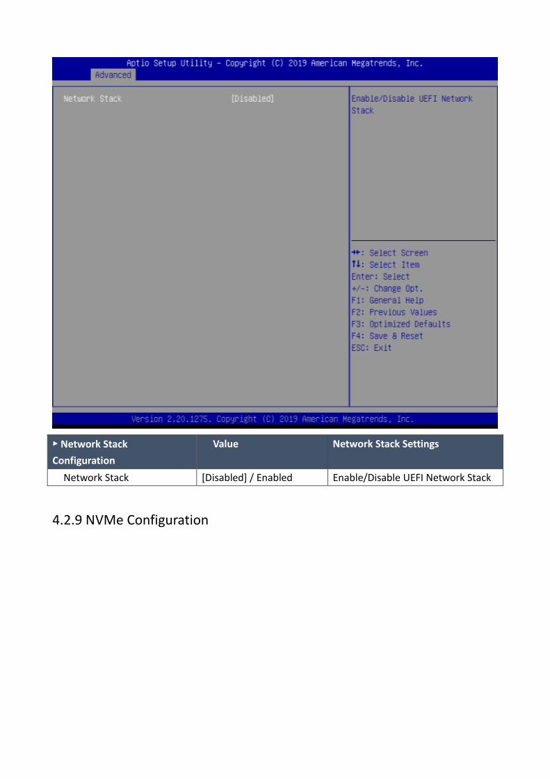
► Network Stack
Configuration
Value Network Stack Settings
Network Stack [Disabled] / Enabled Enable/Disable UEFI Network Stack
4.2.9 NVMe Configuration


4.3 Security Page
Security Value Description
Password Description
Administrator Password xxxx Set Administrator Password
User Password xxxx Set User Password
► HDD Security drive(EX:
xxxxxxxxxxxxx)
HDD Security Configuration
for selected drive
► Secure Boot Secure Boot configuration
► BIOS Update BIOS Update support
4.3.1 Secure Boot


► Secure Boot Value Secure Boot configuration
System Mode xxxx
Secure Boot [Disabled] / Enabled Secure Boot feature is Active if Secure Boot is
Enable, Platform Key(PK) is enrolled and the
System is in User mode. The mode change
requires platform reset
Secure Boot Mode Standard /
[Customer]
Secure Boot mode options: Standard or Custom.
In Custom mode, Secure Boot Policy variables
can be configured by a physically present user
without full aythentication
► Restore Factory Keys [Yes] / No Force System to User Mode.
Install factory default Secure Boot key database
► Reset To Setup Mode [Yes] / No Delete all Secure Boot key databases from
NVRAM
► Key Management Enables expert users to modify Secure Boot
Policy variables without full authentication
Vendor Keys Invalid / Valid

Factory Key Provision [Disabled] / Enabled Install factory default Secure Boot keys after the
platform reset and while the System is in Setup
mode
► Restore Factory Keys [Yes] / No Force System to User Mode.
Install factory default Secure Boot key database
► Reset To Setup Mode [Yes] / No Delete all Secure Boot key databases from
NVRAM
► Export Secure Boot
variables
Drive: \Path Copy NVRAM content of Secure Boot variables
to files in a root folder on a file system device
► Enroll Efi Image xxxxxxxxxxxxxxxxxxx Allow the image to run in Secure Boot mode.
Enroll SHA256 Hash certificate of a PE image
into Authorized Signature Database (db)
Device Guard ready
► Remove ‘UEFI CA’
from DB
Device Guard ready system must not list
'Microsoft UEFI CA' Certificate in Authorized
Signature database (db)
► Remove DB defaults [Yes] / No Restore DB variable to factory defaults
Secure Boot variables | Size | Keys |
Key Source
► Platform Key(PK) [Details] / Export /
Update / Delete
Enroll Factory Defaults or load certificates from
a file:
1.Public Key Certificate:
a)EFI_SIGNATURE_LIST
b)EFI_CERT_X509 (DER)
c)EFI_CERT_RSA2048 (bin)
d)EFI_CERT_SHAXXX
2.Authenticated UEFI Variable
3. EFI PE/COFF Image(SHA256)
Key Source:
Factory, External,Mixed
► Key Exchange Keys [Details] / Export /
Update / Append /
Delete
Enroll Factory Defaults or load certificates from
a file:
1.Public Key Certificate:
a)EFI_SIGNATURE_LIST
b)EFI_CERT_X509 (DER)
c)EFI_CERT_RSA2048 (bin)
d)EFI_CERT_SHAXXX
2.Authenticated UEFI Variable

3. EFI PE/COFF Image(SHA256)
Key Source:
Factory, External,Mixed
► Authorized Signatures [Details] / Export /
Update / Append /
Delete
Enroll Factory Defaults or load certificates from
a file:
1.Public Key Certificate:
a)EFI_SIGNATURE_LIST
b)EFI_CERT_X509 (DER)
c)EFI_CERT_RSA2048 (bin)
d)EFI_CERT_SHAXXX
2.Authenticated UEFI Variable
3. EFI PE/COFF Image(SHA256)
Key Source:
Factory, External,Mixed
► Forbidden Signatures [Details] / Export /
Update / Append /
Delete
Enroll Factory Defaults or load certificates from
a file:
1.Public Key Certificate:
a)EFI_SIGNATURE_LIST
b)EFI_CERT_X509 (DER)
c)EFI_CERT_RSA2048 (bin)
d)EFI_CERT_SHAXXX
2.Authenticated UEFI Variable
3. EFI PE/COFF Image(SHA256)
Key Source:
Factory, External,Mixed
► Authorized
TimeStamps
[Details] / Export /
Update / Append /
Delete
Enroll Factory Defaults or load certificates from
a file:
1.Public Key Certificate:
a)EFI_SIGNATURE_LIST
b)EFI_CERT_X509 (DER)
c)EFI_CERT_RSA2048 (bin)
d)EFI_CERT_SHAXXX
2.Authenticated UEFI Variable
3. EFI PE/COFF Image(SHA256)
Key Source:
Factory, External,Mixed
► OsRecovery
Signatures
[Details] / Export /
Update / Append /
Delete
Enroll Factory Defaults or load certificates from
a file:
1.Public Key Certificate:
a)EFI_SIGNATURE_LIST

b)EFI_CERT_X509 (DER)
c)EFI_CERT_RSA2048 (bin)
d)EFI_CERT_SHAXXX
2.Authenticated UEFI Variable
3. EFI PE/COFF Image(SHA256)
Key Source:
Factory, External,Mixed
4.3.2 BIOS Update

4.4 Boot Page
Boot Value Description
Setup Prompt Timeout 1 Number of seconds to wait for
setup activation key.
65535(0xFFFF) means indefinite
waiting.
Bootup NumLock State On / [Off] Select the keyboard NumLock state
FIXED BOOT ORDER
Priorities
Boot Optoin #1 [USB Floppy] / CD/DVD / USB
CD/DVD / Hard Disk / USB Key /
USB Hard Disk / Network /
Disable
Sets the system boot orfer
Boot Optoin #2 USB Floppy / [CD/DVD] / USB
CD/DVD / Hard Disk / USB Key /
Sets the system boot orfer

USB Hard Disk / Network /
Disable
Boot Optoin #3 USB Floppy / CD/DVD / [USB
CD/DVD] / Hard Disk / USB Key /
USB Hard Disk / Network /
Disable
Sets the system boot orfer
Boot Optoin #4 USB Floppy / CD/DVD / USB
CD/DVD / [Hard Disk] / USB Key /
USB Hard Disk / Network /
Disable
Sets the system boot orfer
Boot Optoin #5 USB Floppy / CD/DVD / USB
CD/DVD / Hard Disk / [USB Key] /
USB Hard Disk / Network /
Disable
Sets the system boot orfer
Boot Optoin #6 USB Floppy / CD/DVD / USB
CD/DVD / Hard Disk / USB Key /
[USB Hard Disk] / Network /
Disable
Sets the system boot orfer
Boot Optoin #7 USB Floppy / CD/DVD / USB
CD/DVD / Hard Disk / USB Key /
USB Hard Disk / [Network] /
Disable
Sets the system boot orfer

4.5 Save & Exit Page
Save & Exit Description
Save Changes and Reset Reset the system after saving the changes.
Discard Changes and Reset Reset system setup without saving any changes.
Load Optimized Defaults Restore/Load Default values for all the setup options.