mw9087 series card otdr operation manual - dl.cdn … · mw9087 series card otdr operation manual...
TRANSCRIPT

Document No.: M-W3543AE-8.0
ANRITSU CORPORATION
MW9087 Series Card OTDR
Operation Manual
For safety and warning information, please read this
manual before attempting to use the equipment.
Keep this manual with the equipment.
Eighth Edition

ii
Safety Symbols
To prevent the risk of personal injury or loss related to equipment malfunction, Anritsu Corporation uses the
following safety symbols to indicate safety-related information. Ensure that you clearly understand the meanings of
the symbols BEFORE using the equipment. Some or all of the following symbols may be used on all Anritsu
equipment. In addition, there may be other labels attached to products that are not shown in the diagrams in this
manual.
Symbols used in manual This indicates a very dangerous procedure that could result in serious injury or death if not performed properly.
This indicates a hazardous procedure that could result in serious injury or death if not performed properly. This indicates a hazardous procedure or danger that could result in light-to-severe injury, or loss related to equipment malfunction, if proper precautions are not taken.
Safety Symbols Used on Equipment and in Manual The following safety symbols are used inside or on the equipment near operation locations to provide information
about safety items and operation precautions. Ensure that you clearly understand the meanings of the symbols and
take the necessary precautions BEFORE using the equipment.
This indicates a prohibited operation. The prohibited operation is indicated symbolically in or near the barred circle.
This indicates an obligatory safety precaution. The obligatory operation is
indicated symbolically in or near the circle. This indicates a warning or caution. The contents are indicated symbolically in or
near the triangle. This indicates a note. The contents are described in the box. These indicate that the marked part should be recycled.
MW9087 Series Card OTDR Operation Manual 2 June 2011 (First Edition) 17 June 2015 (Eighth Edition) Copyright © 2011-2015, ANRITSU CORPORATION. All rights reserved. No part of this manual may be reproduced without the prior written permission of the publisher. The contents of this manual may be changed without prior notice. Printed in Japan
DANGER
WARNING
CAUTION

For Safety
iii
WARNING
ALWAYS refer to the operation manual when working near locations
at which the alert mark shown on the left is attached. If the advice in
the operation manual is not followed there is a risk of personal injury
or reduced equipment performance. The alert mark shown on the left
may also be used with other marks and descriptions to indicate other
dangers.
Overvoltage Category
This equipment complies with overvoltage category II defined in IEC
61010. DO NOT connect this equipment to the power supply of
overvoltage category III or IV.
Laser radiation warning
NEVER look directly into the cable connector on the equipment
nor into the end of a cable connected to the equipment. There is a
risk of injury if laser radiation enters the eye.
The Laser Safety label is attached to the equipment for safety use
as indicated in "Laser Safety" later in this section.
To ensure that the equipment is grounded, always use the supplied
3-pin power cord, and insert the plug into an outlet with a ground
terminal. If power is supplied without grounding the equipment, there
is a risk of receiving a severe or fatal electric shock or causing
damage to the internal components.
Only qualified service personnel with a knowledge of electrical fire and
shock hazards should service this equipment. This equipment cannot
be repaired by the operator. DO NOT attempt to remove the
equipment covers or unit covers or to disassemble internal
components. There are high-voltage parts in this equipment
presenting a risk of severe injury or fatal electric shock to untrained
personnel. In addition, there is a risk of damage to precision
components.
Electric Shock
Repair

For Safety
iv
WARNING
The performance-guarantee seal verifies the integrity of the equipment.
To ensure the continued integrity of the equipment, only Anritsu
service personnel, or service personnel of an Anritsu sales
representative, should break this seal to repair or calibrate the
equipment. Be careful not to break the seal by opening the
equipment or unit covers.If the performance-guarantee seal is
broken by you or a third party, the performance of the equipment
cannot be guaranteed.
This equipment should always be positioned in the correct manner. If
the cabinet is turned on its side, etc., it will be unstable and may be
damaged if it falls over as a result of receiving a slight mechanical
shock.
Always set up the equipment in a position where the power switch
can be reached without difficulty.
Falling Over
Calibration

For Safety
v
Class 1, and 1M indicate the danger degree of the laser radiation
specified below according to IEC 60825-1:2007.
Class 1: Lasers that are safe under reasonably foreseeable conditions of operation, including the use of optical instruments for intrabeam viewing.
Class 1M: Lasers emitting in the wavelength range from 302.5 to 4000 nm that are safe under reasonably foreseeable conditions of operation, but may be hazardous if the user employs optics
within the beam. Two conditions apply:
a) for diverging beams, if the user views the laser output with certain optical instruments (for example, eye loupes, magnifiers and microscopes) within a distance of 100 mm;
or
b) for collimated beams, if the user views the laser output with certain optical instruments (for example, telescopes and binoculars).
CAUTION
Use of controls or adjustments or performance of procedures other than those specified herein may result in hazardous radiation exposure.
The use of optical instruments with this product will increase eye
hazard.
WARNING
The laser in this equipment is classified as Class 1 or 1M according to
the IEC 60825-1:2007 standard, and is safe under reasonably
foreseeable operating conditions.
Never use optical instruments to directly view Class 1M laser products.
Doing so may result in serious damage to the eyes.
Laser Safety

For Safety
vi
Table 1 Laser Safety Classifications Based on IEC 60825-1:2007
Model Name Class
Max. Optical Output
Power (W)*
Pulse Width (s)/Repetition
Rate
Emitted Waveleng
th (nm)
Beam Divergence
(deg)
Incorporated Laser
Specification (refer to Table
2)
Laser Aperture
MW9087B 1 0.15 20×10–6/
0.019 1650 11.5 a) Figure 1, [1]
MW9087D 1M 0.60 20×10–6/
0.019 1550 11.5 b) Figure 1, [1]
*: Indicates the possible optical output power when each and every
reasonably foreseeable single-fault condition is included.
Table 2 Incorporated Laser Specification
Incorporated Laser
Max. Optical Output Power
(W)*
Pulse Width (s)/Repetition Rate
Emitted Wavelength
(nm)
Beam Divergence
(deg)
a) < 0.30 20×10–6/0.019 1650 11.5
b) < 1.20 20×10–6/0.019 1550 11.5
*: Maximum output power is the estimated value when something
breaks down.

For Safety
vii
Table 3 Indication Labels on Product (Ex: Label list)
Type Sample Affixed to: Model Name
1 Explanation Figure 1, A MW9087B
2 Explanation Figure 2, B MW9087D
3 Certification Figure 2, C All Models
4 Identification Figure 2, D All Models

For Safety
viii
Laser Radiation Markings
A [1]
Figure 1 Locations of Laser Beam Apertures and Affixed Labels
C DB
Figure 2 Label Locations

For Safety
ix
CAUTION
The OTDR Module outputs high-power optical pulses. Disconnect the
communication equipments from the optical fibers before a
measurement, or the optical sensor of the equipment may be broken.
This equipment is designed for an industrial environment.
In a residential environment, this equipment may cause radio
interference in which case the user may be required to take adequate
measures.
Exposure to corrosive gases such as hydrogen sulfide, sulfurous acid,
and hydrogen chloride will cause faults and failures.
Note that some organic solvents release corrosive gases.
Disconnect from
Communication
Use in a Residential
Environment
Use in Corrosive
Atmospheres

x
Equipment Certificate Anritsu Corporation certifies that this equipment was tested before shipment
using calibrated measuring instruments with direct traceability to public
testing organizations recognized by national research laboratories, including
the National Institute of Advanced Industrial Science and Technology, and
the National Institute of Information and Communications Technology, and
was found to meet the published specifications.
Anritsu Warranty Anritsu Corporation will repair this equipment free-of-charge if a malfunction
occurs within one year after shipment due to a manufacturing fault.
However, software fixes will be made in accordance with the separate
Software End-User License Agreement. Moreover, Anritsu Corporation will
deem this warranty void when:
The fault is outside the scope of the warranty conditions separately
described in the operation manual.
The fault is due to mishandling, misuse, or unauthorized modification or
repair of the equipment by the customer.
The fault is due to severe usage clearly exceeding normal usage.
The fault is due to improper or insufficient maintenance by the customer.
The fault is due to natural disaster, including fire, wind, flooding,
earthquake, lightning strike, or volcanic ash, etc.
The fault is due to damage caused by acts of destruction, including civil
disturbance, riot, or war, etc.
The fault is due to explosion, accident, or breakdown of any other
machinery, facility, or plant, etc.
The fault is due to use of non-specified peripheral or applied equipment
or parts, or consumables, etc.
The fault is due to use of a non-specified power supply or in a
non-specified installation location.
The fault is due to use in unusual environments(Note).
The fault is due to activities or ingress of living organisms, such as
insects, spiders, fungus, pollen, or seeds.
In addition, this warranty is valid only for the original equipment purchaser. It
is not transferable if the equipment is resold.
Anritsu Corporation shall assume no liability for injury or financial loss of the
customer due to the use of or a failure to be able to use this equipment.

xi
Note:
For the purpose of this Warranty, "unusual environments" means use:
In places of direct sunlight
In dusty places
In liquids, such as water, oil, or organic solvents, and medical fluids, or
places where these liquids may adhere
In salty air or in places where chemically active gases (sulfur dioxide,
hydrogen sulfide, chlorine, ammonia, nitrogen dioxide, or hydrogen
chloride etc.) are present
In places where high-intensity static electric charges or electromagnetic
fields are present
In places where abnormal power voltages (high or low) or instantaneous
power failures occur
In places where condensation occurs
In the presence of lubricating oil mists
In places at an altitude of more than 2,000 m
In the presence of frequent vibration or mechanical shock, such as in
cars, ships, or airplanes
Anritsu Corporation Contact In the event that this equipment malfunctions, contact an Anritsu Service and
Sales office. Contact information can be found on the last page of the printed
version of this manual, and is available in a separate file on the CD version.

xii
Notes On Export Management This product and its manuals may require an Export License/Approval by
the Government of the product's country of origin for re-export from your
country.
Before re-exporting the product or manuals, please contact us to confirm
whether they are export-controlled items or not.
When you dispose of export-controlled items, the products/manuals need
to be broken/shredded so as not to be unlawfully used for military purpose.
Reuse parts Anritsu group promotes recycling activities in order to reuse available
resources and save energy. This product may use recycled parts
(mechanical components) that conform to Anritsu’s quality standards.
Lifetime of Parts The life span of certain parts used in this instrument is determined by the
operating time or the power-on time. Due consideration should be given to
the life spans of these parts when performing continuous operation over an
extended period. These parts must be replaced at the customer's expense
even if within the guaranteed period described in Warranty at the beginning
of this manual. For details on life span, refer to the corresponding section in
this manual.

xiii
Crossed-out Wheeled Bin Symbol Equipment marked with the Crossed-out Wheeled Bin Symbol complies with
council directive 2012/19/EC (the “WEEE Directive”) in European Union.
For Products placed on the EU market after August 13, 2005, please contact
your local Anritsu representative at the end of the product's useful life to
arrange disposal in accordance with your initial contract and the local law.

xiv
Software End-User License Agreement (EULA) Please read this Software End-User License Agreement (hereafter this EULA) carefully before using (includes executing, copying, registering, etc.) this software (includes programs, databases, scenarios, etc., used to operate, set, etc., Anritsu electronic equipment). By reading this EULA and using this software, you are agreeing to be bound by the terms of its contents and Anritsu Corporation (hereafter Anritsu) hereby grants you the right to use this Software with the Anritsu-specified equipment (hereafter Equipment) for the purposes set out in this EULA.
1. Grant of License and Limitations 1. Regardless of whether this Software was
purchased from or provided free-of-charge by Anritsu, you agree not to rent, lease, lend, or otherwise distribute this Software to third parties and further agree not to disassemble, recompile, reverse engineer, modify, or create derivative works of this Software.
2. You may make one copy of this Software for backup purposes only.
3. You are not permitted to reverse engineer this software.
4. This EULA allows you to install one copy of this Software on one piece of Equipment.
2. Disclaimers To the extent not prohibited by law, in no
event shall Anritsu be liable for personal injury, or any incidental, special, indirect or consequential damages whatsoever, including, without limitation, damages for loss of profits, loss of data, business interruption or any other commercial damages or losses, arising out of or related to your use or inability to use this Software.
3. Limitation of Liability a. If a fault (bug) is discovered in this Software,
preventing operation as described in the operation manual or specifications whether or not the customer uses this software as described in the manual, Anritsu shall at its own discretion, fix the bug, or exchange the software, or suggest a workaround, free-of-charge. However, notwithstanding the above, the following items shall be excluded from repair and warranty.
i) If this Software is deemed to be used for
purposes not described in the operation
manual or specifications.
ii) If this Software is used in conjunction with
other non-Anritsu-approved software.
iii) Recovery of lost or damaged data.
iv) If this Software or the Equipment has been
modified, repaired, or otherwise altered
without Anritsu's prior approval.
v) For any other reasons out of Anritsu's direct
control and responsibility, such as but not
limited to, natural disasters, software virus
infections, etc. b. Expenses incurred for transport, hotel, daily
allowance, etc., for on-site repairs by Anritsu engineers necessitated by the above faults shall be borne by you.
c. The warranty period for faults listed in article 3a above covered by this EULA shall be either 6 months from the date of purchase of this Software or 30 days after the date of repair, whichever is longer.

xv
4. Export Restrictions You may not use or otherwise export or
re-export directly or indirectly this Software except as authorized by Japanese and United States law. In particular, this software may not be exported or re-exported (a) into any Japanese or US embargoed countries or (b) to anyone on the Japanese or US Treasury Department's list of Specially Designated Nationals or the US Department of Commerce Denied Persons List or Entity List. By using this Software, you warrant that you are not located in any such country or on any such list. You also agree that you will not use this Software for any purposes prohibited by Japanese and US law, including, without limitation, the development, design and manufacture or production of missiles or nuclear, chemical or biological weapons of mass destruction.
5. Termination Anritsu shall deem this EULA terminated if
you violate any conditions described herein. This EULA shall also be terminated if the conditions herein cannot be continued for any good reason, such as violation of copyrights, patents, or other laws and ordinances.
6. Reparations If Anritsu suffers any loss, financial or
otherwise, due to your violation of the terms of this EULA, Anritsu shall have the right to seek proportional damages from you.
7. Responsibility after Termination Upon termination of this EULA in
accordance with item 5, you shall cease all use of this Software immediately and shall as directed by Anritsu either destroy or return this Software and any backup copies, full or partial, to Anritsu.
8. Dispute Resolution If matters of dispute or items not covered by
this EULA arise, they shall be resolved by negotiations in good faith between you and Anritsu.
9. Court of Jurisdiction
This EULA shall be interpreted in accordance with Japanese law and any disputes that cannot be resolved by negotiation described in Article 8 shall be settled by the Japanese courts.

xvi
Cautions against computer virus infection Copying files and data
Only files that have been provided directly from Anritsu or generated
using Anritsu equipment should be copied to the instrument.
All other required files should be transferred by means of USB or
CompactFlash media after undergoing a thorough virus check.
Adding software
Do not download or install software that has not been specifically
recommended or licensed by Anritsu.
Network connections
Ensure that the network has sufficient anti-virus security protection in
place.

xvii
CE Conformity Marking Anritsu affixes the CE conformity marking on the following product(s) in
accordance with the Council Directive 93/68/EEC to indicate that they
conform to the EMC and LVD directive of the European Union (EU).
CE marking
1. Product Model Model: MW9087 Series Card OTDR
2. Applied Directive EMC: Directive 2004/108/EC
LVD: Directive 2006/95/EC
3. Applied Standards
EMC: Emission: EN 61326-1: 2013 (Class A)
Immunity: EN 61326-1: 2013 (Table 2)
Performance Criteria* IEC 61000-4-2 (ESD) B
IEC 61000-4-3 (EMF) A
IEC 61000-4-4 (Burst) B
IEC 61000-4-5 (Surge) B
IEC 61000-4-6 (CRF) A
IEC 61000-4-8 (RPFMF) A
IEC 61000-4-11 (V dip/short) B, C
*: Performance Criteria
A: The equipment shall continue to operate as intended
during and after the test. No degradation of
performance or loss of function is allowed below a
performance level specified by the manufacturer, when
the equipment is used as intended. The performance
level may be replaced by a permissible loss of
performance. If the minimum performance level or the
permissible performance loss is not specified by the
manufacturer, either of these may be derived from the
product description and documentation and what the
user may reasonably expect from the equipment if used
as intended.
B: The equipment shall continue to operate as intended
after the test. No degradation of performance or loss of
function is allowed below a performance level specified

xviii
by the manufacturer, when the equipment is used as
intended. The performance level may be replaced by a
permissible loss of performance. During the test,
degradation of performance is however allowed. No
change of actual operating state or stored data is
allowed. If the minimum performance level or the
permissible performance loss is not specified by the
manufacturer, either of these may be derived from the
product description and documentation and what the
user may reasonably expect from the equipment if used
as intended.
C: Temporary loss of function is allowed, provided the
function is self-recoverable or can be restored by the
operation of the controls.
Harmonic current emissions:
EN 61000-3-2: 2006 +A1:2009 A2:2009
: No limits apply for this equipment with an active input
power under 75 W.
LVD: EN 61010-1: 2010 (Pollution Degree 2)
4. Authorized representative
Name: Murray Coleman
Head of Customer Service EMEA
ANRITSU EMEA Ltd.
Address, city: 200 Capability Green, Luton
Bedfordshire, LU1 3LU
Country: United Kingdom

xix
C-Tick Conformity Marking Anritsu affixes the C-Tick mark on the following product(s) in accordance
with the regulation to indicate that they conform to the EMC framework of
Australia/New Zealand.
C-Tick mark
1. Product Model Model: MW9087 Series Card OTDR
2. Applied Standards
EMC: Emission: EN 61326-1: 2013 (Class A equipment)

xx

I
About This Manual The configuration of the MW9087 Series Card OTDR operation manual is divided into the following three parts: Card OTDR Mainframe, LED Interface, and Password function. This manual describes the operation/maintenance method for MW9087 Series Card OTDR.
Refer to Chapter 2 "Before Use" to understand the setting of this device and precautions.
Also, refer to Chapter 3 "Measurement Method" to understand the overview of operation flow.
MW9087 Series Card OTDR Option 001 LED Interface Operation Manual
Described the operation method of the LED interface.
Describes basic operations of MW9087 Series Card OTDR
MW9087 Series Card OTDR Operation Manual (This manual)
MW9087 Series Operation Manual Configuration
MW9087 Series Card OTDR Password Function Option Operation Manual
Describes the operation method of the password function.

II
Table of Contents
For Safety .................................................... iii
About This Manual........................................ I
Chapter 1 Outline ....................................... 1-1 1.1 Introduction to MW9087 Series Card OTDR ............. 1-2
1.2 Features ..................................................................... 1-3
1.3 Outline of OTDR ........................................................ 1-5
Chapter 2 Before Use ................................. 2-1 2.1 Product Configuration ................................................ 2-2 2.2 Names of Parts .......................................................... 2-3 2.3 Installing the Card OTDR ........................................... 2-5 2.4 Power Connection ..................................................... 2-8 2.5 Communication Settings ............................................ 2-9 2.6 Installation/Uninstallation for USB Serial Driver ........ 2-11 2.7 Confirmation of COM Ports ........................................ 2-25 2.8 Connecting the Optical Fiber Cable ........................... 2-29 2.9 Cautions on Handling Optical Fiber Cables ............... 2-31 2.10 Replacing the Optical Connector ............................... 2-33 2.11 Precautions ................................................................ 2-34
Chapter 3 Measurement Method ............... 3-1 3.1 Setting before Measurement ..................................... 3-2
3.2 Measurement Procedures ......................................... 3-3
3.3 Setting Measurement Conditions............................... 3-4
3.4 Measurement ............................................................. 3-5
3.5 Waveform Analysis .................................................... 3-6
3.6 Calculation Method .................................................... 3-7
3.7 Obtaining State .......................................................... 3-14

III
1
2
3
4
5
Appendix
Chapter 4 Command Reference ................ 4-1 4.1 Command Format ...................................................... 4-2
4.2 Transmission Procedures .......................................... 4-3
4.3 Command List ............................................................ 4-5
4.4 Command Details ...................................................... 4-15
4.5 Error Code ................................................................. 4-53
Chapter 5 Performance Test and
Maintenance .............................. 5-1 5.1 Performance Test ...................................................... 5-2
5.2 Updating Software ..................................................... 5-16
5.3 Cautions on Storage .................................................. 5-17
5.4 Transporting and Disposal ......................................... 5-18
Appendix A Specifications ......................... A-1
Appendix B Relationship between Pulse
Width Distance Range ............ B-1
Appendix C Factory Shipment Defaults .... C-1
Appendix D Command Compatibility ........ D-1
Appendix E Performance Test Result
Form ........................................ E-1

IV.

Chapter 1 Outline
1-1
1
Outline
This chapter explains the features of the MW9087 Series Card OTDR
1.1 Introduction to MW9087 Series Card OTDR ............. 1-2 1.2 Features ..................................................................... 1-3 1.3 Outline of OTDR ........................................................ 1-5

Chapter 1 Outline
1-2
1.1 Introduction to MW9087 Series Card OTDR MW9087 Series Card OTDR is a module form for the optical fiber measurement device.
Figure 1.1-1 Card OTDR Appearance (MW9087B)
This device has multiple models depending on wavelengths and dynamic ranges.
Table 1.1-1 Model Name of Card OTDR
Model Wavelength Dynamic range (Typ.)
MW9087B 1650 nm 41 dB MW9087D 1550 nm 50 dB
1550 nm wavelength is used for communications. To monitor the fiber loss/deterioration or breaks without effects on communications, the model with wavelength of 1650 nm is used. To measure the fiber loss of the wavelength used for communications, the model with wavelength of 1550 nm is used.
If the fiber loss is large or the communication path has the fiber loss due to optical coupler, the model with a large dynamic range is used.

1.2 Features
1-3
1
Outline
1.2 Features The MW9087 Series Card OTDR has been developed in order to monitor faults in the optical fiber system. You can control it via Ethernet; therefore, it can be used for automatic/remote measurement.
Partial sampling Distance range to be measured can be set, and only the range set can be measured. This feature will shorten the measurement time.
Normal measurement Partial sampling
Distance range Distance range
Measurement range
Distance
Distance
Figure 1.2-1 Normal Measurement and Partial Sampling
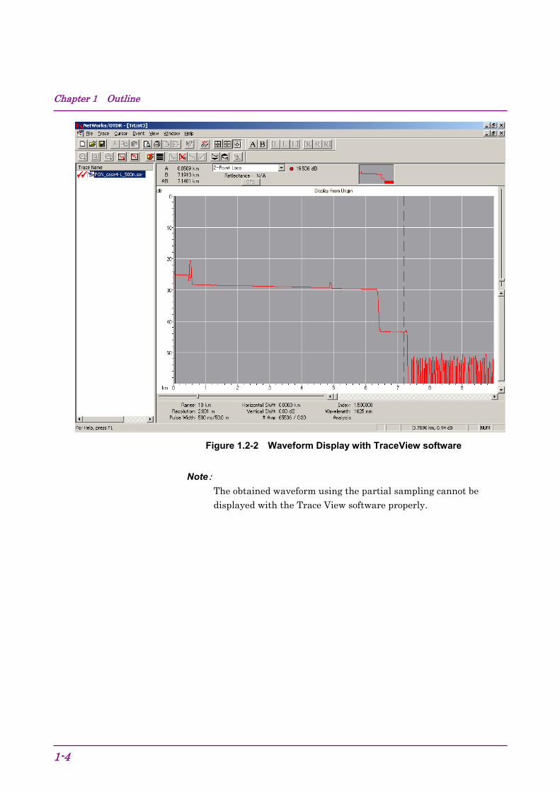
SR-4731 file format The measurement results can be saved with Telcordia standard SR-4731 OTDR Data Format-compliant files. These files have the extension of SOR, and waveforms can be displayed with TraceView software. This software is available from the following URL.
http://www.anritsu.com/en-US/Downloads/Software/Drivers/Software-Downloads/DWL2761.aspx
Chapter 1 Outline
1-4
Figure 1.2-2 Waveform Display with TraceView software
Note: The obtained waveform using the partial sampling cannot be displayed with the Trace View software properly.

1.3 Outline of OTDR
1-5
1
Outline
1.3 Outline of OTDR OTDR operating principle OTDR (Optical Time Domain Reflectometer) transmits brief optical pulses to the fiber to measure the intensity and time difference of lights reflected from within the fiber. The distance of the reflection point is calculated from the time difference, light speed, and index of refraction (IOR) of the fiber. The light attenuation (fiber loss) is calculated from the light intensity reflected from within the fiber.
Leve
l
Time
Tran
smitt
ed l
ight
le
vel
Rec
eive
d lig
ht
leve
l
Measurement time
Pulse width
Distance range
Distance
OTDR Fiber
Time change between the light pulse transmitted and the light level received by OTDR
Waveform data of OTDR
Figure 1.3-1 OTDR Transmitted/Received Waveform and Waveform Data

Chapter 1 Outline
1-6
The maximum measurable distance (distance range) is determined by the time when OTDR measures the received light level after the optical pulse is transmitted.
Transmitted optical pulse is reflected little by little within the fiber. The more distant the reflected light is, the lower is the light level received by OTDR. Therefore, the waveform of measurement result becomes a downward-sloping rectilinear graph.
OTDR fiber measurement In places where the fiber is connected or damaged, the fiber loss or the light reflection may become larger. These changes make the waveform of measurement result discontinuous.
Leve
l Loss occurred
Distance
Reflection occurred
Figure 1.3-2 Detection of Fiber Loss and Reflection
Waveform change with pulse width The larger is the transmitted optical pulse width, the higher is the received light level. Therefore, make the pulse width larger for the measurement system with large fiber loss such as the case of a long distance range.
Leve
l When pulse width is large
Distance
Leve
l
When pulse width is narrow
Distance
Figure 1.3-3 Level Change with Pulse Width

1.3 Outline of OTDR
1-7
1
Outline
The narrower is the transmitted optical pulse width, the shorter is the optical pulse length within the fiber. Therefore, the loss change within the fiber can be measured to the direction of length finely (at high resolution).
Le
vel
When pulse width is large
Distance
Leve
l
When pulse width is narrow
Distance
Figure 1.3-4 Resolution Change with Pulse Width

Chapter 1 Outline
1-8.

Chapter 2 Before Use
2-1
2
Before U
se
This chapter provides information that should be thoroughly understood before actually using the Card OTDR, such as the installation method, setting items, and precautions.
2.1 Product Configuration ................................................... 2-2 2.2 Names of Parts ............................................................. 2-3 2.3 Installing the Card OTDR .............................................. 2-5
2.3.1 Installation method ........................................... 2-5 2.3.2 Dimension ......................................................... 2-7
2.4 Power Connection ........................................................ 2-8 2.5 Communication Settings ............................................... 2-9
2.5.1 Interface ............................................................ 2-9 2.5.2 Network setting ................................................. 2-9 2.5.3 Serial port setting ............................................ 2-10
2.6 Installation/Uninstallation for USB Serial Driver ......... 2-11 2.6.1 Installation (Windows XP) .............................. 2-11 2.6.2 Installation (Windows 7) ................................. 2-14 2.6.3 Uninstallation (Window XP) ............................ 2-19 2.6.4 Uninstallation (Windows 7) ............................. 2-22
2.7 Confirmation of COM Ports ......................................... 2-25 2.7.1 Confirmation of COM Ports (Windows XP) .... 2-25 2.7.2 Confirmation of COM Ports (Windows 7) ....... 2-27
2.8 Connecting the Optical Fiber Cable ............................ 2-29 2.9 Cautions on Handling Optical Fiber Cables ................ 2-31 2.10 Replacing the Optical Connector ................................ 2-33 2.11 Precautions ................................................................. 2-34

Chapter 2 Before Use
2-2
2.1 Product Configuration The standard composition of the MW9087 Series Card OTDR (hereafter, Card OTDR) is listed in the following table. After unpacking, check the packing list and make sure that all the components are included. If any part is missing or damaged, contact Anritsu or your Anritsu sales agent immediately.
Table 2.1-1 Standard Configuration
Item Model Product Name Q'ty
Mainframe MW9087B/D Card OTDR 1 Accessories CD-ROM 1
The MW9087 Series Card OTDR Operation Manual (W3543AE) and the USB serial driver are included in the CD-ROM.

2.2 Names of Parts
2-3
2
Before U
se
2.2 Names of Parts The following figure shows the names of parts.
USB connector
Ethernet Power lamp
Power connector
Optical connector
Figure 2.2-1 Front Panel (MW9087B)
Venting hole
Figure 2.2-2 Upper Surface Panel

Chapter 2 Before Use
2-4
Table 2.2-1 Name and Function
Name Function
Power lamp Lights when power is supplied. Power connector
Input terminal for DC power
Optical connector
Input/Output connector for optical pulse measurement
USB connector Used for serial port communication Ethernet connector
Connects the Lan cable.
Venting hole
WARNING NEVER look directly into the laser radiation emitted from
the Card OTDR optical connector or the end of the cable
connected to the Card OTDR. If you do so, the laser light
may damage your eyes.

2.3 Installing the Card OTDR
2-5
2
Before U
se
2.3 Installing the Card OTDR 2.3.1 Installation method
Install the Card OTDR top surface or side up as shown in Figure 2.3.1-1.
Figure 2.3.1-1 Installation Orientation
A venting hole is installed in the Card OTDR to prevent the internal temperature from rising. Install the Card OTDR in a location with the vents at least 10 cm away from walls, peripherals or other obstructions so as not to block the fan perimeter.
10 cm or more
10 cm or more 10 cm or more
Figure 2.3.1-2 Vent Airflow System
The Card OTDR releases the air to the top surface. When two units of the Card OTDR are used, place them so that the air released from one unit is not received by the other unit.

Chapter 2 Before Use
2-6
Air Flow
Air Flow
Figure 2.3.1-3 Arrangement for Multiple Units
Although the Card OTDR operates at an ambient temperature of 0° to 50°C, avoid using it in locations, such as the following, since it may cause failure.
In places of direct sunlight
In dusty places
Outdoors
In liquids, such as water, oil, or organic solvents, and medical fluids, or places where these liquids may adhere
In salty air or in place chemically active gases (sulfur dioxide, hydrogen sulfide, chlorine, ammonia, nitrogen dioxide, or hydrogen chloride etc.) are present
In places where high-intensity static electric charges or electromagnetic fields are present
In places where abnormal power voltages (high or low) or instantaneous power failures occur
In places where condensation occurs
In the presence of lubricating oil mists
In places at an altitude of more than 2,000 m
In the presence of frequent vibration or mechanical shock, such as in cars, ships, or airplanes
Locations where there is a risk of equipment toppling over, etc.

2.3 Installing the Card OTDR
2-7
2
Before U
se
2.3.2 Dimension The Card OTDR has holes on bottom panel to secure with screws. Install it using screws of M3 (8 mm or less). The arrangement for screw holes is shown in the figure below. The unit is mm.
Screw hole Venting hole
Figure 2.3.2-1 Dimensional Drawing (Bottom View)

Chapter 2 Before Use
2-8
2.4 Power Connection The Card OTDR operates with the DC 12 V power supply and it starts when the power is supplied. Connect the polarities correctly as shown in Figure 2.4-1.
+
–
Figure 2.4-1 Power Connector Polarity
Hosiden DC Jack HEC-0470-01-630 is used as the power input pin. The recommended DC plug dimension is φ2.1 × φ5.5 × 9.5 mm (Refer to Figure 2.4-2).
9.5
Φ5.
5 1.5 Φ2.1
Figure 2.4-2 Dimension Figure for Power Connector
The specifications for the power source are as follows.
Table 2.4-1 Specifications for Power Source
Item Specifications
Power Voltage 12 V±10% Power Consumption ≤20 W
WARNING Be sure to check that the power source is set within the
range specified. Supplying power exceeding the rated
range may result in electrical shock, fire, failure, or
malfunction.

2.5 Communication Settings
2-9
2
Before U
se
2.5 Communication Settings 2.5.1 Interface
The enabled interfaces are as follows.
PC side: RJ45 port, USB port type A
The Card OTDR side: RJ45 port, USB port type B When the Card OTDR is connected to a PC, use the Ethernet cable or USB cable of type A-B. Also Anritsu driver is required when the USB interface is used. Refer to Section 2.6 “Installation/Uninstallation for USB Serial Driver to install it in a PC. When the Card OTDR is connected to a PC using the Ethernet cable directly, use the cross cable.
2.5.2 Network setting When the Ethernet setting is not changed from the factory default, the PC should be set according to the following values.
Communication mode Autonegotiation
IP address 192.168.1.2
Subnet mask 255.255.255.0
Default gateway None
Port number 2288
Use NETNEG command to change the communication mode setting and NET command to change the Network setting. The Card OTDR is restarted using the RST command after setting the Network. The set values have been reflected since the Card OTDR is restarted.

Chapter 2 Before Use
2-10
2.5.3 Serial port setting Set the serial port of the communication control software to be operated on the PC as follows.
Baud rate (bit/sec) 115200 bps
Data bit 8 bits
Parity None
Stop bit 1 bit
Flow control Hardware
Note:
The communication condition of the serial port cannot be changed.

2.6 Installation/Uninstallation for USB Serial Driver
2-11
2
Before U
se
2.6 Installation/Uninstallation for USB Serial Driver 2.6.1 Installation (Windows XP)
The installation method for USB serial driver is explained with the example of Windows XP.
1. Copy the UsbSerialDrivers folder of the CD-ROM to the PC.
2. Power on the Card OTDR and PC and connect the USB cable.
3. When the cable is connected, the Welcome to the Found New Hardware Wizard is displayed.
4. Select "No, not this time" and click Next>.
Note:
The above window is not displayed depending on the version of the Windows XP.
5. The installation selection window is displayed.

Chapter 2 Before Use
2-12
6. Select "Install from a list of specific location (Advanced)" and click Next>.
7. The windows describing "Please choose your search and installation option" is displayed.
8. Select "Search for the best driver in these location" and put the check mark in the "Include this location in the search:". Then, specify the RemoteControl folder saved at the procedure 1. (When clicking Browse, the folder is enabled.)
9. Then, when clicking Next>, the driver is installed.
10. When the installation confirmation window is displayed, click Continue Anyway.

2.6 Installation/Uninstallation for USB Serial Driver
2-13
2
Before U
se
11. When the completion message is displayed, installing the driver is completed. Click Finish.

Chapter 2 Before Use
2-14
2.6.2 Installation (Windows 7) The installation method for USB serial driver is explained with the example of Windows 7.
1. Copy the UsbSerialDrivers folder of the CD-ROM to the PC.
2. Power on the Card OTDR and PC and connect the USB cable.
3. Click Computer from Start Menu.
4. Click System Programs.

2.6 Installation/Uninstallation for USB Serial Driver
2-15
2
Before U
se
5. Click Device Manager.
6. Check that MT9080 COM is displayed on the device manager.
7. Right-click MT9080 COM and select Updating Driver Software.

Chapter 2 Before Use
2-16
8. Click "Browse my computer for driver software".
9. Specify the Win7 folder in the UsbSerialDrivers saved at the step 1. When using the Windows 32-bit version, specify the Windows 32- bit folder. When using the Windows 64-bit version, specify the Windows 64-bit folder. When clicking Browse…, the folder is enabled.

2.6 Installation/Uninstallation for USB Serial Driver
2-17
2
Before U
se
10. Then, when clicking Next, the driver installation is started.
11. When the installation confirmation screen is displayed, click "Install this driver software anyway".
12. When the completion message is displayed, the process is completed normally. Click Close.
13. The current port number is displayed on the right side of the OTDR USB Serial.

Chapter 2 Before Use
2-18

2.6 Installation/Uninstallation for USB Serial Driver
2-19
2
Before U
se
2.6.3 Uninstallation (Window XP) Avoid turning off the power during uninstallation of the USB serial driver since the PC communicates with the Card OTDR.
1. Turn on the power of the mainframe and the PC, and connect them with a USB cable.
2. Click Control Panel from the Start menu of Windows.
3. Double-click System.
4. Click Hardware tab.
5. Click Device Manager.

Chapter 2 Before Use
2-20
6. Double-click the port (COM and LPT).
7. Right-click OTDR USB serial and click Uninstall.
8. When the Confirm Device Removal window is displayed, click OK.

2.6 Installation/Uninstallation for USB Serial Driver
2-21
2
Before U
se
9. Confirm that the OTDR USB Serial is removed.
10. Close the opened windows such as the device manager and system properties.
11. Unplug the USB cable connected to the Card OTDR.

Chapter 2 Before Use
2-22
2.6.4 Uninstallation (Windows 7) Uninstallation Procedures for the USB serial driver:
As the PC communicates with the Card OTDR during uninstalltion of the USB serial driver, set the Card OTDR to the remote control mode before uninstallation.
1. Power on the Card OTDR and PC and connect the USB cable.
2. Click Computer from the Start Menu.
3. Click System Properties.

2.6 Installation/Uninstallation for USB Serial Driver
2-23
2
Before U
se
4. Click Device Manager.
5. Double-click the ports (COM and LPT).
6. Right-click OTDR USB Serial and click Uninstall.

Chapter 2 Before Use
2-24
7. The confirmation message for deleting the device, click OK.
8. Check that OTDR USB Serial is deleted.
9. Close the properties for the device manager, system, and etc.
10. Unplug the USB cable connected to the Card OTDR.

2.7 Confirmation of COM Ports
2-25
2
Before U
se
2.7 Confirmation of COM Ports 2.7.1 Confirmation of COM Ports (Windows XP)
Confirmation Procedures for COM Ports
Avoid turning off the power during confirmation of COM port since the PC communicates with the Card OTDR.
1. Power on the Card OTDR and PC to connect the USB cable.
2. Click the control panel from the Windows start menu.
3. Double-click System.
4. Click Hardware tab.
5. Click Device Manager.

Chapter 2 Before Use
2-26
6. Double-click the port (COM and LPT).
7. Check the number displayed on the right side of the OTDR USB Serial. The COM port number is acquired automatically. The COM port number varies with the PC to be installed.

2.7 Confirmation of COM Ports
2-27
2
Before U
se
2.7.2 Confirmation of COM Ports (Windows 7) Confirmation Procedures for COM Ports
Communicate with the Card OTDR while confirming the COM port.
1. Power on the Card OTDR and PC and connect the USB cable.
2. Click Computer from the Start Menu.
3. Click System Properties.

Chapter 2 Before Use
2-28
4. Click Device Manager.
5. Double-click the ports (COM and LPT).
6. Check the displayed number on the right side of the OTDR USB Serial. The COM port number is acquired automatically. So, the COM port number varies with the PC.

2.8 Connecting the Optical Fiber Cable
2-29
2
Before U
se
2.8 Connecting the Optical Fiber Cable Cleaning the Optical Fiber End Surface
Before connecting the optical fiber cable, clean the ferrule end surface with the dedicated cleaning device. In some cases, the cleaning of the ferrule side surface is effective.
Lights pass within the optical fiber of about 10 micron in diameter. The
optical fiber may cause loss or reflection which prevents correct
measurement even with very little dirt. Make sure to clean the optical
connector before measurement.
Cleaning ferrule side surface Cleaning ferrule end surface
Push the ferrule end surface on the right groove of theferrule cleaner, turn it right and left, and then slide it. Next, shift the optical connector 90 degrees and clean it on the left groove in the same way.
Adapter cleaner
Figure 2.8-1 Cleaning the Ferrule
Cleaning the Measurement Port (Optical Connector)
Remove the replaceable connector to clean the ferrule end surface. Also, clean the dirt on sleeve within the replaceable connector with the adapter cleaner.

Chapter 2 Before Use
2-30
Adapter cleaner
Replaceable connector
Inside of the cardOTDR
Latch
Lever
Remove the replaceable connector to clean the ferrule end surface.
Figure 2.8-2 Cleaning the Optical Connector
Connect the optical fiber cable to the optical connector on the front panel.
Figure 2.8-3 Connection of Optical Fiber Cable
WARNING NEVER look into the cable connecting end of the optical
connector of the OTDR or the end of the cable connected
to the OTDR. If you do so, the laser light may damage
your eyes.

2.9 Cautions on Handling Optical Fiber Cables
2-31
2
Before U
se
2.9 Cautions on Handling Optical Fiber Cables Optical fiber cables may degrade in performance or be damaged if handled improperly.
Note the following points when handling them.
CAUTION
Do not pull the cable when removing the connector.
Doing so may break the optical fiber inside the cable, or
remove the cable sheath from the optical connector.
CAUTION
Do not excessively bend, fold, or pinch an optical fiber cable.
Doing so may break the optical fiber inside the cable.
Keep the bend radius of an optical fiber cable at 30 mm or
more. If the radius is less, optical fiber cable loss will
increase.
CAUTION
Do not excessively pull on or twist an optical fiber cable.
Also, do not hang anything by using a cable. Doing so may
break the optical fiber inside the cable.

Chapter 2 Before Use
2-32
CAUTION
Be careful not to hit the end of an optical connector against anything hard such as the floor or a desk by dropping the optical fiber cable.
Doing so may damage the connector end and increase
connection loss.
WARNING
Do not touch the end of a broken optical fiber cable.
The broken optical fiber may pierce the skin, causing
injury.
CAUTION
Do not disassemble optical connectors.
Doing so may cause part to break or the performance to
degrade.

2.10 Replacing the Optical Connector
2-33
2
Before U
se
2.10 Replacing the Optical Connector The optical connector of the Card OTDR has SC as standard. This optical connector can be replaced with other connectors depending on the intended use.
To replace the optical connector
1. Pull the adapter lever towards you until the latch is released.
2. Remove the connector by lifting it.
Latch
Adapter lever
Figure 2.10-1 How to Remove the Optical Connector
For the types of optical connector, refer to Figure 2.10-2.
SC ST HMS-10/ADINFC
Internal MW9087
Figure 2.10-2 Types of Optical Connector

Chapter 2 Before Use
2-34.
2.11 Precautions Disconnect from communication equipments
If output pulses of the Card OTDR enter the communication device, the light receiving section of the device may be damaged. Before the measurement is started, remove the communication device from the optical fiber.
Limit to the interface
The Card OTDR has USB (serial port) and Ethernet. The serial port can be used only for the network setting of Ethernet. Also, the serial port and Ethernet cannot be used simultaneously.
Condensation
If the Card OTDR is carried from a low-temperature environment to a warm room, there is a danger of condensation in it. In this case, allow the Card OTDR to dry completely before turning on its power.
Results of auto search function
Auto measurement function is a supporting function to reduce the workload of an operator, while it may generate false detection. If false detection is presumed, check the measured waveform data.

Chapter 3 Measurement Method
3-1
3
Measurem
ent Method
This chapter explains the measurement procedures and calculation method.
3.1 Settings before Measurement ....................................... 3-2 3.1.1 Network settings ............................................... 3-2 3.1.2 System settings ................................................ 3-2
3.2 Measurement Procedures ............................................ 3-3 3.3 Setting Measurement Conditions.................................. 3-4 3.4 Measurement ................................................................ 3-5 3.5 Waveform Analysis ....................................................... 3-6 3.6 Calculation Method ....................................................... 3-7
3.6.1 Loss measurement ........................................... 3-7 3.6.2 Return loss measurement ................................ 3-9 3.6.3 Event evaluation ............................................. 3-10 3.6.4 Approximate line method ................................ 3-12
3.7 Obtaining State ........................................................... 3-14

Chapter 3 Measurement Method
3-2
3.1 Settings before Measurement The network and system are set before performing the measurement.
3.1.1 Network settings To control the Card OTDR via the Ethernet, set the following items.
Command 1. Connect the Card OTDR and PC via the USB
cable.
2. Set the Ethernet address and port number, etc. via RS-232C.
NET
3. Set the Ethernet communication speed and flow control via RS-232C.
NETNEG
4. Restart the Card OTDR. RST 5. Connect the Card OTDR and PC via the Ethernet
cable.
6. Set the timeout time via the Ethernet. CONNTM Other than the network settings, communicate with the Card OTDR via the Ethernet
3.1.2 System settings Check the self diagnosis and set time of the Card OTDR via the Ethernet.
CAUTION The optical pulse is output when performing self diagnosis. When the fiber is connected to the communication device, remove the fiber before performing the self diagnosis. The receiving parts of the communication device may be damaged depending on the optical pulse output from the Card OTDR.
Command 1. Connect the Card OTDR and PC via the Ethernet
cable.
2. Perform the self diagnosis. SLFTST 3. Check the date and time settings. DATE2

3.2 Measurement Procedures
3-3
3
Measurem
ent Method
3.2 Measurement Procedures The following figure shows the fiber loss measurement procedures using the Card OTDR.
Set the measurement condition.
Start the measurement.
Start
Finish the measurement?
Read the measurement results from the card OTDR.
Yes
No
End
Figure 3.2-1 Procedures for Fiber Loss Measurement

Chapter 3 Measurement Method
3-4
3.3 Setting Measurement Conditions The measurement conditions such as the distance range, correction values, and averaging process method are set. Command 1. Select the wavelength. WLS 2. Set the pulse width. PLA
PLS 3. Set the distance range. DSA
DSR 4. Set the sampling mode. RES 5. When the partial sampling is executed, set the
range. SSMP
6. Set IOR (fiber index of refraction). IOR 7. Set the attenuation of the attenuator. ATA
ATT ATV
8. Set the backscatter coefficient level correction value.
CAL
9. Set the averaging processing method. ALA
10. When the enhance mode is used, set the mode. ENH The INI command allows restoring measurement conditions to the factory default settings.

3.4 Measurement
3-5
3
Measurem
ent Method
3.4 Measurement The measurement is performed using the following procedures and the waveform data is obtained. Command 1. Connect the optical fiber to be measured to the
Card OTDR.
2. Set whether averaging process is executed or not.
AVG
3. Set whether smoothing process is executed or not.
SMTH
4. Set the distance offset for the optical connector of the Card OTDR.
OFS
5. Change Marker mode or Event table mode. MES* 6. Set the approximate line method. APR 7. Start the measurement. LD 8. Query whether the measurement is finished or
not. STS
9. Query whether the waveform data is created or not.
WAV
10. Obtain the waveform data. SOR format Binary format
SRLV HDFG GETFILE DAT
11. When the averaging process is executed, query the number of times.
AVE
*: When Marker mode is selected, an event is not detected automatically. The settings for the optical connector distance offset and approximate line method can be changed even after the measurement is completed. The data obtained with SOR format can be displayed with Trace View software.

Chapter 3 Measurement Method
3-6
3.5 Waveform Analysis Waveform data analysis allows the detection of fiber reflection/loss occurrence positions and the measurement of reflection/loss amount. Command 1. Set the fiber far end threshold. THF 2. Set the reflection threshold. THR2 3. Set the splice loss threshold. THS 4. Query the number of detected events. AUT 5. Query the measurement result and event type of
the event number. EVN2
6. Query the measurement result of the splice loss. SPLICE 7. Query the measurement result of the return loss. REFLCT 8. Query the measurement result of the loss. LOS2 9. Query the measurement result of all the losses. TLOS
MKDR When thresholds are changed, events are redetected.
The INI command allows restoring thresholds to the factory default settings.

3.6 Calculation Method
3-7
3
Measurem
ent Method
3.6 Calculation Method The waveform analysis calculation method is as follows.
3.6.1 Loss measurement Loss LOS2 command displays the level difference of X1 marker and X2 marker in dB as the loss measurement result. When the X1 marker level is higher than the X2 marker level, the loss will be a positive value.
21 LLLoss −=
Loss:Loss (dB) L1: X1 marker level L2: X2 marker level
When connecting a fiber with a different Backscatter coefficient level correction value, sometimes the loss value may become negative. LOS2 command is used to measure the loss between two points on the optical fiber.
Distance
X1 X2
Loss
Leve
l
Figure 3.6.1-1 Measurement Method for Loss

Chapter 3 Measurement Method
3-8
Splice loss measurement SPLICE command measures the loss of points where the optical fiber is connected with connectors, fusion splices, and couplers. The measured waveform of splice points of the optical fiber looks like the solid line in the following figure. It is observed that the loss occurs over the distance of ΔL depending on the settings of pulse width and sampling count. In fact, loss only occurs at the splice points as shown by the dotted lines. LOS2 command cannot measure the loss shown with the dotted line.
Distance
Splice point
∆L
Loss Level
Figure 3.6.1-2 Example of Fiber Connection Measurement
Using SPLICE command, two approximate lines are generated from four markers range using the two-point method or the least square method. The level difference between the approximate lines at cursor B is the measured splice point loss.
Distance
X1
X3
X2
X4
Approximate line of waveform between X1 marker and X2 marker
Approximate line of waveform between X3 marker and X4 marker
Loss
Level
Figure 3.6.1-3 Splice loss Measurement Method

3.6 Calculation Method
3-9
3
Measurem
ent Method
3.6.2 Return loss measurement The return loss measurement method obtained with REFLCT command is as follows. Detect the waveform local maximum level L1. Measure the Rayleigh scattering level L2 just before the local maximum level.
Distance
Leve
l L2
L1
Figure 3.6.2-1 Return Loss Measurement Method
Obtain the return loss by the following formula.
IORPWcBSCBSL
BSLORL
R
LL
××××=
−+−=−
2
)}110+log)+{log10 51010
12
α
ORL: Return loss (dB) R: Rayleigh scattering loss c: Light velocity 3×10⁸ (m/s) BSC: Backscatter light coefficient IOR: Index of refraction PW: Pulse width L1: Local maximum level L2: Previous Rayleigh scattering level

Chapter 3 Measurement Method
3-10
3.6.3 Event evaluation The event type evaluation method obtained with EVN2 command is as follows. Reflection Fresnel reflection has been generated with a light connector or mechanical splice. Either one of the points below is evaluated as the reflection event. • Point where the reflection rate measurement result is equal to or
greater than the reflection threshold set with THR2 command. • Point where the loss measurement result is equal to or greater than
the splice loss threshold set with THS command. Saturation Point where the reflection light level is high and the measurement level is saturated among the reflection events. Non-reflective The loss without Fresnel reflection has been generated with fusion splice or fiber bending loss. The point where the loss measurement result is equal to or greater than the splice loss threshold set with THS command is evaluated as the non-reflective event. Group When there are multiple points where the loss measurement result is equal to or greater than the splice loss threshold set with THS command, the points where the loss of each event cannot be measured due to its short interval are evaluated as the group event. The measured loss result is displayed as the total of the losses of the multiple points. Sometimes, reducing the pulse width makes it possible to separate the events.

3.6 Calculation Method
3-11
3
Measurem
ent Method
Distance
Level
Loss
Figure 3.6.3-1 Group Event Loss
Far end This is the far end of the fiber point or a break in point of the fiber. The point where the loss measurement result is equal to or greater than the far end threshold set with THF command is evaluated as the far end event.

Chapter 3 Measurement Method
3-12
3.6.4 Approximate line method The approximate line method set with APR command is explained.
Suppose, the two lines of L1 and L2 from the measurement data in order to obtain the splice point loss as shown in the figure below.
L1
L2
L1
L2
Figure 3.6.4-1 Method to Obtain Splice Point Loss
There are two methods, the least square method and two-point method, to obtain these lines.
Two-point method (2PA)
The line which goes through the two markers is the approximate line.
Least square method (LSA)
The least square method obtains the line that is the minimum distance variation from all data which exist between markers to the line.
y
x
(x1,y1)
(xi,yi)
i=yi–(a+bxi)
L=y=a+bx
A+bxi
(xn,yn)
Figure 3.6.4-2 Approximate Line and Gap Amount
Line L is y = a + bx, when the variation of the distance from n points (x1, y1), (x2, y2), …, (xn, yn) is the minimum as shown in the figure above. Obtain gaps 1,2,3, … from each point to line L including variables a and b, and obtain variables a and b so that E, the sum of the square of i (gap of each point) becomes the minimum to determine line L.

3.6 Calculation Method
3-13
3
Measu
remen
t Meth
od
i=yi–(a+bxi)n
E=i2=(y1–a–bx1)2+(y2–a–bx2)2+•••+(yn–a–bxn)2 i=1
The necessary and sufficient conditions for E to become the minimum
with this formula are Ea
=0 , Eb
=0 .
When these formulas are solved, variables a and b can be obtained as follows.
,
Here, , .

Chapter 3 Measurement Method
3-14.
3.7 Obtaining State To obtain the information of the Card OTDR, use the following commands. Command Error information query ERR
System information query MINF Measurement state query STS
For the detail of error messages, refer to Section 4.5 "Error Code."

Chapter 4 Command Reference
4-1
4
Comm
and Reference
This chapter explains the command format, transmission procedure, and details of commands.
4.1 Command Format ......................................................... 4-2 4.2 Transmission Procedures ............................................. 4-3 4.3 Command List ............................................................... 4-5
4.3.1 Alphabetical order ............................................. 4-5 4.3.2 Setup Measurement Condition ......................... 4-8 4.3.3 Setup for Measurement .................................. 4-10 4.3.4 Query for Measurement Results .................... 4-11 4.3.5 Query for Statuses .......................................... 4-12 4.3.6 File Data Access ............................................. 4-12 4.3.7 System Maintenance ...................................... 4-13 4.3.8 Network Configuration .................................... 4-13 4.3.9 Other Setup .................................................... 4-14
4.4 Command Details ....................................................... 4-15 4.4.1 Description of Message Explanations ............ 4-15 4.4.2 Measurement Condition Setup ....................... 4-16 4.4.3 Settings for Measurement .............................. 4-28 4.4.4 Querying Measurement Results ..................... 4-32 4.4.5 Queries for statuses ....................................... 4-42 4.4.6 Settings for Data File ...................................... 4-44 4.4.7 System Maintenance ...................................... 4-46 4.4.8 Network Configuration .................................... 4-50 4.4.9 Other Settings ................................................. 4-52
4.5 Error Code .................................................................. 4-53

Chapter 4 Command Reference
4-2
4.1 Command Format The transmission format is classified as follows.
For text data:
Command Name
Data Part
TRM
• Command Name: The control command or query command is entered.
• Data Part: Setting parameters of commands and values obtained from the Card OTDR are entered.
• TRM: When transmitting commands, the terminator (CR + LF) is added. When receiving responses, the terminator (CR + LF) is added.
For binary data (control command):
Command Name
Data size
(binary)
Data part (binary)
• Command Name: The control command is entered. • Data Size: The byte length (big endian format) of the data part is
indicated with 4 bytes. • Data Part: The terminator is not added. For binary data (response):
Data Size
(binary)
Data Part (binary)
• Data Size: The byte length (big endian format) of the data part is indicated with 4 bytes.
• Data Part: The terminator is not added.

4.2 Transmission Procedures
4-3
4
Comm
and Reference
4.2 Transmission Procedures (1) When the command is processed normally
When the control command is transmitted to the Card OTDR, processing the command normally returns ANS0. After it is received, the PC program (called the control program) transmits the following command.
PC Card OTDR
Control Command → Normal
End ← ANS0
For the query command, a response is returned.
After the response is received, the control program transmits the next command.
PC Card OTDR
Query Command → Normal
End ← Response
Note:
If the control program transmits the next command before the Card OTDR returns the response, the Card OTDR discards the command received by the time of response transmission (does not return the response for the command that has been received).

Chapter 4 Command Reference
4-4
(2) When the command is not processed normally
When the Card OTDR cannot execute the received command, the negative response (ANS***) is returned. Enter an error code to ***.
PC Card OTDR
Command → Abnormal ← ANS***
(3) When there is no response
When the command from the control program stops for 30 seconds during transmission, the Card OTDR returns the error (ANS 143) as timeout.
PC Card OTDR
Command→
No response (Timeout 30 seconds) Abnormal
← ANS 143***

4.3 Command List
4-5
4
Comm
and Reference
4.3 Command List Outline of each command is described in the following tables. Refer to 4.4 for the details of each command.
4.3.1 Alphabetical order Table 4.3.1-1 Command List
Control Command
Query Command Function
A ALA ALA? Averaging Mode Setup APR APR? Approximate Line Method Setup ATA ATA? Attenuator Setup in Auto Mode ATT ATT? Attenuator Setup
– ATV? Query for available Attenuator
– AUT? Query for the result of Auto Search
– AVE? Query for Average Mode AVG AVG? Average Setup
B – BSL? Query for Backscatter Coefficient
Level C
CAL CAL? Backscatter Level Calibration Setup
CONNTM CONNTM? Timeout Interval Setup D
– DAT? Query for Waveform Data DATE2 DATE2? Date & Time Setup
DSA DSA? Distance Range Mode Setup DSR DSR? Distance Range Setup
DWNLD DWNLD? Software Download E
– ERR? Query for Error Status ENH ENH? High Dynamic Range Mode Setup
– EVN2? Query for Event Analysis Result G
– GETFILE? Data File Acquisition of Waveform H
HDFG HDFG? Data Flag Setup

Chapter 4 Command Reference
4-6
Table 4.3.1-1 Command List (Cont'd)
Control Command
Query Command Function
I INI – Initialization
IOR IOR? IOR Setup L
LD LD? OTDR Measurement Start/Stop
– LOS2? Query for Insertion Loss Measurement Results
M MES MES? Mode Setup
– MINF? Query for the Equipment Profile
– MKDR? Query for Total Insertion Loss Analysis Range
N NET NET? Network Configuration
NETNEG NETNEG? Ethernet Speed Setup O
OFS OFS? Relative Distance Setup P
PLA PLA? Pulse Width Mode Setup
PLS PLS? Pulse Width Setup R
– REFLCT? Query for Return Loss
RES RES? Sampling Auto Setup
RST – Reset Execution S
SETFILE – Waveform Data File Transfer
SLFTST SLFTST? Self-diagnosis
– SMPINF? Query for Sampling Conditions
SMTH SMTH? Smoothing Setup
– SPLICE? Query for Splice Loss Measurement
SRLV SRLV? File Data Format Setup
SSMP SSMP? Partial Sampling Mode Setup
– SSMPINF? Query for Partial Sampling Value
– STS? Query for the Equipment Status (OTDR)

4.3 Command List
4-7
4
Comm
and Reference
Table 4.3.1-1 Command List (Cont'd)
Control Command
Query Command Function
T THF THF? Fiber-end Threshold Setup
THR2 THR2? Reflection Threshold Setup
THS THS? Slice Loss Threshold Setup
– TLOS? Query for Total Loss W
– WAV? Query for Waveform Data Status
WLS WLS? Wavelengths Setup

Chapter 4 Command Reference
4-8
4.3.2 Setup Measurement Condition CNT: Control command QUR: Query command RSP: Response for query command
Table 4.3.2-1 Commands for Measurement Conditions
No Function Message Remarks
1 Wavelengths Setup
CNT WLS w w: Wavelength: 1 = 1μm 0: Current Wavelength [ ] can be omitted, 1: All n: Wavelength w1, …, wn: Wavelength
QUR WLS? {[0]|1}
RSP WLS w WLS n, w1, w2, wn
2 Distance Range Mode Setup
CNT DSA 0: Manual Setup 1: Automatic Setup QUR DSA?
RSP DSA {0|1}
3 Distance range
CNT DSR d d: Distance Range 1 = 1 m Available range depends on pulse width and sampling mode
QUR DSR?
RSP DSR d
4 Pulse Width Mode Setup
CNT PLA 0: Manual Setup 1: Automatic Setup QUR PLA?
RSP PLA {0|1}
5 Pulse width Setup
CNT PLS p p: Pulse width 1 = 1 ns Available pulse width depends on distance range.
QUR PLS? RSP PLS p
6
High Dynamic Range Mode Setup
CNT ENH {0|1} m: Mode 0: Standard 2: High Dynamic Range
QUR ENH?
RSP ENH m
7 IOR Setup CNT IOR i
i: IOR 1=1 1.000000 to 1.999999 QUR IOR:
RSP IOR i
8 Average Mode Setup
CNT ALA m, [v] m: Mode 0: Manual by number 1: Manual by time 2: Auto V= Set value 1=1 Number of time/ 1 second [ ] can be omitted. Vn: Number Vt: Time
QUR ALA?
RSP ALA m, Vn, Vt
9 Sampling Mode Setup
CNT RES {0|1|3} 0: Coarse 1: Medium 3: Fine
QUR RES? RSP RES {0|1|3}

4.3 Command List
4-9
4
Comm
and Reference
Table 4.3.2-1 Commands for Measurement Conditions (Cont'd)
No Function Message Remarks
10 Partial Sampling Mode Setup
CNT SSMP s,r,q s: Sampling start 1.00=1.00 m r: Resolution 1.00=1.00 m p: Number of point
0: 5001pt 1: 20001 or 25001 pt 2:100001 or 125001 pt
QUR SSMP? RSP SSMP s,r,q
11 Query for Sampling Point and Resolution
CNT --- p: Sampling point r: Resolution 1.00=1.00 m QUR SMPINF?
RSP SMPINF p,r
12
Query for Partial Sampling Status
CNT --- s: Sampling start distance 1.00=1.00 m r: Resolution 1.00=1.00 m p: Number of points
QUR SSMPINF? RSP SSMPINF s,r,p
13 Attenuation Auto Setup
CNT ATA 0: Manual Setup 1: Automatic Setup QUR ATA?
RSP ATA {0|1}
14 Attenuator Setup
CNT ATT a a: Attenuation 1 = 1 dB "***" in Full trace mode QUR ATT?
RSP ATT a
15 Query for available Attenuation
CNT --- P: Pulse width a1, •••, an: Attenuation QUR ATV? p
RSP ATV a1,a2,an
16
Query for Backscatter Coefficient Level
CNT --- b: Backscatter coefficient level at current pulse width 1 = –1 dB
QUR BSL? RSP BSL b
17
Backscatter Level Calibration Setup
CNT CAL n
n: –9.99 to +9.99 QUR CAL? RSP CAL n
18 Fiber-end Threshold Setup
CNT THF s s: Threshold, 1 = 1 dB 1 to 99 dB, (1 dB step) QUR THF?
RSP THF s
19 Reflection Threshold Setup
CNT THR2 s: Threshold,1=1 dB –60 to –20 dB (0.1 dB step) QUR THR2?
RSP THR2 s
20 Slice Loss Threshold Setup
CNT THS s s: Threshold, 1 = 1 dB 0.01 to 9.99 dB (0.01 dB step) QUR THS?
RSP THS s

Chapter 4 Command Reference
4-10
4.3.3 Setup for Measurement Table 4.3.3-1 Setup for Measurement
No Function Message Remarks
1 Average Setup CNT AVG {0|1}
0: Real time measurement 1: Average Measurement QUR AVG?
RSP AVG {0|1}
2 Linear Approximation Method Setup
CNT APR {0|1} 0: 2PA 1: LSA QUR APR?
RSP APR {0|1}
3 OTDR Measurement Start/Stop
CNT LD {0|1|2} 0: Measurement stopped 1: Start normal measurement
(In progress) 2: Start partial sampling measurement
( In progress)
QUR LD?
RSP LD {0|1|2}
4 Mode Setup CNT MES {0|1}
0: Marker mode 1: Event table mode QUR MES?
RSP MES {0|1}
5 Relative Distance Setup
CNT OFS l l: Relative distance (zero point) 1 = 1 m QUR OFS?
RSP OFS l
6 Smoothing ON/Off Setup
CNT SMTH {0|1} 0: Smoothing OFF 1: Smoothing ON QUR SMTH?
RSP SMTH {0|1}

4.3 Command List
4-11
4
Comm
and Reference
4.3.4 Query for Measurement Results Table 4.3.4-1 Commands for Querying Measurement Results
No Function Message Remarks
1 Query for Insertion Loss Measurement
CNT --- e: Event position x1: Position X1 x2: Position X2 x3: Position X3 x4: Position X4 v: Event loss
QUR SPLICE? e,x1,x2,x3,x4
RSP SPLICE? e,x1,x2,x3,x4,v
2 Query for Return Loss Measurement Result
CNT --- e: Event position p: Peak position v: Return loss
QUR REFLCT? e,p RSP REFLCT e,p,v
3 Query for Loss Measurement Result
CNT --- x1: Marker position X1 x2: Marker position X2 v: Loss
QUR LOS2? x1,x2 RSP LOS2 x1,x2,v
4 Query for the result of Auto Search
CNT --- e: Number of Event d: Fiber length l: Total Loss r: Total Return loss
QUR AUT?
RSP AUT e,d,l,r
5 Query for Event Measurement Result
CNT --- e: Event number d: Distance s: Slice loss r: Return loss l: Total Loss t: Events, types reported
QUR EVN2? e
RSP EVN2 e,d,s,r,l,t
6 Query for Total Loss
CNT --- x1: Marker Position X1 x2: Marker Position X2 t: Total Loss
QUR TLOS? x1,x2 RSP TLOS x1,x2,t
7 Query for Waveform Data
CNT --- s: Data start distance [ ] can be omitted. e: Data end distance [ ] can be omitted. k: Data decimation rate [ ] can be omitted. ds: Data length d: Data
QUR DAT? [s,e,[k]]
RSP ds,d
8 Query for Average Result
CNT --- m: Average mode 0: Manual, 1: Auto k: number b: time
QUR AVE? RSP AVE m,k,b
9 Query for Total Loss Analysis Range
CNT --- s: Start point e: End point QUR MKDR?
RSP MKDR s,e
Chapter 4 Command Reference
4-12
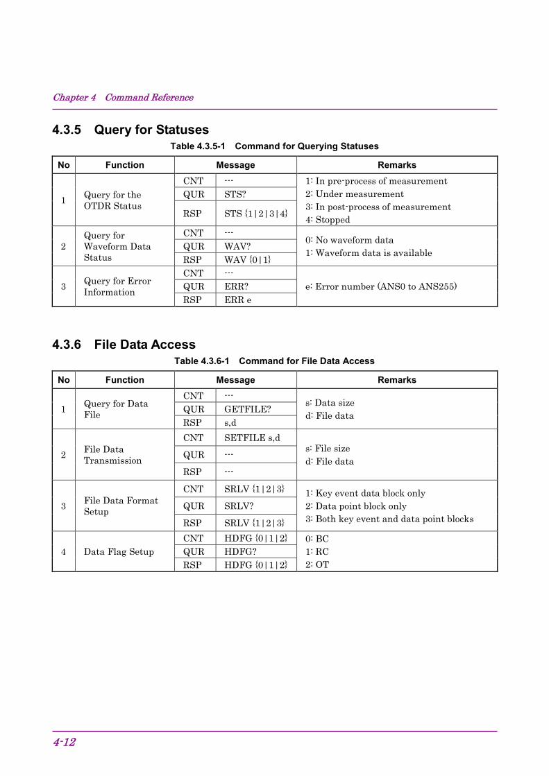
4.3.5 Query for Statuses Table 4.3.5-1 Command for Querying Statuses
No Function Message Remarks
1 Query for the OTDR Status
CNT --- 1: In pre-process of measurement 2: Under measurement 3: In post-process of measurement 4: Stopped
QUR STS?
RSP STS {1|2|3|4}
2 Query for Waveform Data Status
CNT --- 0: No waveform data 1: Waveform data is available QUR WAV?
RSP WAV {0|1}
3 Query for Error Information
CNT --- e: Error number (ANS0 to ANS255) QUR ERR?
RSP ERR e
4.3.6 File Data Access Table 4.3.6-1 Command for File Data Access
No Function Message Remarks
1 Query for Data File
CNT --- s: Data size d: File data QUR GETFILE?
RSP s,d
2 File Data Transmission
CNT SETFILE s,d s: File size d: File data QUR ---
RSP ---
3 File Data Format Setup
CNT SRLV {1|2|3} 1: Key event data block only 2: Data point block only 3: Both key event and data point blocks
QUR SRLV?
RSP SRLV {1|2|3}
4 Data Flag Setup CNT HDFG {0|1|2} 0: BC
1: RC 2: OT
QUR HDFG? RSP HDFG {0|1|2}

4.3 Command List
4-13
4
Comm
and Reference
4.3.7 System Maintenance Table 4.3.7-1 Command for System Maintenance
No Function Message Remarks
1 Date & Time Setup
CNT DATE2 y,m,d,h,mm,s,diff y: year m: month d: day
h: hour mm: minute s: second diff: Time difference from UTC
QUR DATE2? RSP DATE2
y,m,d,h,mm,s,diff
2 Self-Diagnostics
CNT SLFTST l: optical level w: warming up p: power voltage t: internal temperature 0: Normal 1 or more: Failure
QUR SLFTST? RSP SLFTST
l,w,p,t
3 Query for System Information
CNT --- m: maker n: model name c: comment s: serial number mac: mac address v: software version
QUR MINF? RSP MINF
m,n,c,s,mac,v
4 Software Update
CNT DWNLD s,d s: File size d: File data
QUR DWNLD? RSP DWNLD
{0|1|2|3} 0: Software is not received. 1: Software is being updated. 2: Software update is completed. 3: Software update is failed.
4.3.8 Network Configuration Table 4.3.8-1 Command for Network Configuration
No Function Message Remarks
1 Timeout Interval Setup
CNT CONNTM t t: Timeout interval 1 = 1 s QUR CONNTM?
RSP CONNTM t
2 Network Configuration
CNT NET i,p,m,g i: IP address p: port number m: Netmask g: Gateway QUR NET?
RSP NET i,p,m,g
3 Ethernet Speed Setup
CNT NETNEG t,f t: Communication speed (10 or 100 or AUTO)
f: Flow control F:Full H: Half QUR NETNEG? RSP NETNEG t,f
4 Timeout Interval for Alarm Setup
CNT ATO t t: Timeout interval 1 = 1 s QUR ATO?
RSP ATO t

Chapter 4 Command Reference
4-14
4.3.9 Other Setup Table 4.3.9-1 Command for Other Setup
No Function Message Remarks
1 Reset CNT RST
Resets the Card OTDR. QUR --- RSP ---
2 Initialization CNT INI
Sets measurement conditions to the factory default. QUR ---
RSP ---

4.4 Command Details
4-15
4
Comm
and Reference
4.4 Command Details 4.4.1 Description of Message Explanations
Command Syntax "_" between the header and the arguments of the command means a space. Effective argument range Entered value in dB will be rounded off to four decimal places. It will also be converted to a discrete value, for example in 0.1 dB steps, according to the definition of each command. The distance argument entry in IOR calibration mode works as follows. The entered value is inversely converted to a law distance and rounded by current physical data resolution. After acceptable range verification (IOR=1.5), it will be used as an argument of the command.

Chapter 4 Command Reference
4-16
4.4.2 Measurement Condition Setup
(1) Averaging Mode Setup
Command ALA
Description Set the number of times for averaging or number of seconds used in measurement.
Control
ALA_<mode>,[<argument>]
Mode
0: Times 1: Seconds 2: Auto For switching to Auto Times (Seconds), set to Times (Seconds) first, and then set to Auto.
Set value Times: 1 to 9999 times Seconds: 1 to 9999 seconds Auto: none
Query ALA?
Response
ALA_<mode>,< Set times >,< Set seconds >
Mode 0: Times 1: seconds 2: Auto
Set number 1 to 9999 times
Set number 1 to 9999 seconds
Remarks
When the mode is Auto, the value set with the auto setting will be returned. When the mode is Auto and in case of no waveform, the response will be ALA 2,***,*** . [ ] can be omitted.

4.4 Command Details
4-17
4
Comm
and Reference
(2) Attenuator Setup in Auto Mode
Command ATA
Description Set Attenuator in Auto mode.
Control ATA
Query ATA?
Response
ATA_{0|1}
0 Manual Setup
1 Automatic Setup
Remarks When Pulse width is in Auto mode, Attenuator will be set to Auto mode. Also, when Attenuator is changed to Auto mode, the waveform data will be erased.
(3) Attenuator Setup
Command ATT
Description Sets Attenuation.
Control
ATT_<attenuation>
Attenuation
Number rounded down to three decimal places Unit: dB Available attenuation range depends on Pulse width. Available attenuation rang can be obtained using ATV?_<Pulse width> command. When Pulse width setting is in Auto mode, Attenuator will be set to Auto mode automatically.
Query ATT?
Response
ATT_<attenuation>
Attenuation
Numeric value Unit : dB When Attenuator is in Auto mode, the response will be "ATT ***". When Pulse width is in Auto mode, the response will be "ANS103".
Remarks
When Pulse width is in Auto mode, Attenuator will be set to Auto mode. When Attenuation is changed, Auto mode will be released. When the setup value is changed with the command, the waveform data will be erased. However, when Attenuator is set to Auto mode, the waveform data will be erased even without setup value change. Also, if measurement is being executed, the measurement will stop, and it will restart after the command processing has been executed.

Chapter 4 Command Reference
4-18
(4) Query for Available Attenuator
Command ATV
Description Queries available Attenuation values under the specific Pulse width.
Control – – –
Query ATV?_<pulse width>
Pulse width Numeric value Unit: ns
Response ATV_<attenuation>,[<attenuation>]
Attenuation Number of three decimal places Unit: dB
Remarks – – –
(5) Query for Backscatter Coefficient Level
Command BSL
Description Queries Backscatter coefficient level under the present Pulse width.
Control – – –
Query BSL?
Response
BSL_<backscatter coefficient level>
Backscatter coefficient level
Numeric value Unit: dB 1=–1 dB When Pulse width is in Auto mode or in case of no waveform data, the response will be BSL ***.
Remarks – – –

4.4 Command Details
4-19
4
Comm
and Reference
(6) Backscatter Level Calibration Setup
Command CAL
Description Sets the coefficient value to calibrate Backscatter level.
Control
CAL_<coefficient value>
Coefficient value
Number rounded down to three decimal places Unit: dB Acceptable coefficient range: –9.99 to +9.99 In case of waveform data, changing the setup value with CAL command will re-execute auto search. When the setup range is exceeded (including integer or negative numbers), the response will be ANS41. When the parameter data format is incorrect, the response will be ANS42.
Query CAL?
Response CAL_<coefficient value>
Coefficient value –9.99 to +9.99
Remarks – – –
(7) Distance Range Mode Setup
Command DSA
Description Sets the distance range control in Automatic Setup mode.
Control DSA
Query DSA?
Response
DSA_{0|1}
0 Manual Setup
1 Automatic Setup
Remarks Waveform data will be erased as the result of DSA command execution.

Chapter 4 Command Reference
4-20
(8) Distance Range Setup
Command DSR
Description Sets the distance range used at the measurement.
Control
DSR_< Distance Range >
Distance Range
Value without IOR compensation. Unit: m Available distance range per present sampling mode: Medium: No less than 100 km Coarse or Fine: No less than 1 km
Query DSR?
Response
DSR_<Distance Range >
Distance Range
Value without IOR compensation. Unit: m In case of no waveform data in Automatic distance range mode, the response will be "DSR ***".
Remarks Automatic distance range Setup mode will be released as the result of DSR command execution. The waveform data will be erased when Distance range is changed.

4.4 Command Details
4-21
4
Comm
and Reference
(9) High Dynamic Range Mode Setup
Command ENH
Description Sets high dynamic range mode for measurements
Control
ENH_{0|1}
0 Standard Mode
1 High dynamic range mode Available when the pulse width is between 50 ns to 2000 ns.
Query ENH?
Response 0 Standard Mode
1 High dynamic range mode
Remarks The wave form data will be erased when the high dynamic range mode is changed.
(10) IOR Setup
Command IOR
Description Sets IOR for measurements.
Control IOR_<IOR value>
IOR value 1.000000 to 1.999999
Query IOR?
Response IOR?_ <IOR value>
IOR value 1.000000 to 1.999999
Remarks – – –

Chapter 4 Command Reference
4-22
(11) Pulse Width Mode Setup
Command PLA
Description Sets the pulse width to Automatic Setup mode.
Control PLA
Query PLA?
Response
PLA_{0|1}
0 Manual Setup
1 Automatic Setup
Remarks Waveform data will be erased as the result of PLA command execution. Attenuator control is also set in Automatic Setup mode.
(12) Pulse Width Setup
Command PLS
Description Sets the pulse width for measurements.
Control
PLS_<pulse width>
Pulse width
Numeric value Unit: ns The settable range varies with the distance range. Refer to Appendix B "Relationship between Pulse Width and Distance Range".
Query PLS?
Response PLS_<pulse width>
Pulse width Numeric value Unit: ns
Remarks
Automatic pulse width Setup mode will be released as the result of PLS command execution. The wave form data will be erased when the pulse width is changed. When the pulse width is Auto and in case of no waveform, the response will be PLS ***.

4.4 Command Details
4-23
4
Comm
and Reference
(13) Sampling Mode Setup
Command RES
Description Sets Sampling Mode for measurements.
Control
RES_{0|1|3}
0 Coarse: 5001 points
1 Medium: 25001 points Available when Distance range is 1 km or more.
3 Fine: 125001 points Available when Distance range is 100 km or more.
Query RES?
Response
RES_{0|1|3}
0 Coarse
1 Medium
3 Fine
Remarks The wave form data will be erased when the sampling mode is changed.
(14) Query for Sampling Point and Resolution
Command SMPINF
Description Queries sampling information.
Control — — —
Query SMPINF?
Response
SMPINF_< number of points >,<modified resolution(m)>
Number of points Numeric value
Modified resolution
Value without IOR compensation. Unit: m
Remarks When distance range is in Auto mode and in case of no waveform data, the response will be SMPINF ***,***.

Chapter 4 Command Reference
4-24
(15) Partial Sampling Measurement Condition Setup
Command SSMP
Description Sets the conditions for the partial sampling measurements.
Control
SSMP_< start distance(m)>,< resolution(m)>,< number of points >
Start distance
Set the sampling start distance. Value rounded down to two decimal places with IOR compensation. Unit: m
Resolution Value without IOR compensation. Unit: m
Number of points
0: 5001 points 1: 20001 points or 25001 points 2: 100001 points or 125001 points
Query SSMP?
Response
SSMP_< start distance(m)>,< resolution(m)>,< number of points >
Start distance Set the sampling start distance. Value rounded down to two decimal places with IOR compensation. Unit: m
Resolution Value without IOR compensation. Unit: m
Number of points
0: 5001 points 1: 20001 points or 25001 points 2: 100001 points or 125001 points
Remarks
When distance offset is set with OFS command, the start distance is the distance from the distance offset. Example: When the position of start distance is set at 1000 m and distance offset at 0 m, then absolute distance of the start distance is 1000 m. When distance offset is 100 m, absolute distance of the start distance is 1100 m.
MW9087B
Offset 100 m
Sart distance 1000 m
1100 m
Partial Sampling Range= Resolution×(Number of points-1)

4.4 Command Details
4-25
4
Comm
and Reference
(16) Query for Partial Sampling Value
Command SSMPINF
Description Queries set value for the partial sampling measurements.
Control –––
Query SSMPINF?
Response
SSMPINF_<Compensation start distance(m)>, <Modified resolution(m)>,< Sampling point >
Compensation start distance
A number rounded down to two decimal places in the resolution of measurement data with IOR compensation. Unit: m
Resolution Value with IOR compensation. Unit: m
Sampling point Numeric value
Remarks – – –
(17) Fiber-end Threshold Setup
Command THF
Description Sets threshold.
Control
THF_<threshold>
Threshold
Fiber -end threshold, integer in dB. Available threshold value: Integer from 1 to 99 dB In case of waveform data, changing the setup value with THF command will re-execute auto search. When the setup range is exceeded (including integer or negative numbers), the response will be ANS41. When the parameter data type is incorrect, the response will be ANS42.
Query THF?
Response THF_<threshold>
Threshold 1 to 99 dB
Remarks – – –

Chapter 4 Command Reference
4-26
(18) Reflection Threshold Setup
Command THR2
Description Sets Reflection threshold.
Control
THR2_<threshold>
Threshold Value
Reflection threshold, value rounded down to one decimal place in dB. Available threshold value: –60.0 dB to –20.0 dB In case of waveform data, changing the setup value with THR2 command will re-execute auto search. When the setup range is exceeded (including integer or negative numbers), the response will be ANS41. When the parameter data type is incorrect, the response will be ANS42.
Query THR2?
Response THR2_<threshold>
Threshold Value –60.0 dB to –20.0 dB
Remarks – – –
(19) Splice Loss Threshold Setup
Command THS
Description Sets Slice loss threshold.
Control
THS_<threshold>
Threshold
Splice loss threshold, value rounded down to two decimal places in dB. Available threshold value: 0.01 dB to 9.99 dB In case of waveform data, changing the setup value with THS command will re-execute auto search. When the setup range is exceeded (including integer or negative numbers), the response will be ANS41. When the parameter data type is incorrect, the response will be ANS42.
Query THS?
Response THS_<threshold>
Threshold 0.01 dB to 9.99 dB
Remarks – – –

4.4 Command Details
4-27
4
Comm
and Reference
(20) Wavelength Setup
Command WLS
Description Sets the measurement wavelength.
Control
WLS_<wavelength>
Wavelength
Value rounded down to three decimal places Unit: μm The wavelength to be set varies with the optical units. The settable wavelength will be obtained by the query command, WLS? 1.
Query
WLS?_{[0]|1}
0 Queries currently set wavelength
1 Queries all of the available wavelengths
Response In case of the argument = "0": WLS_<wavelength>
In case of argument = "1": WLS_<number of wavelength n>,<wavelength 1>,・・・,<wavelength n>
Remarks [ ] can be omitted. When WLS command is executed, the waveform data will be erased.

Chapter 4 Command Reference
4-28
4.4.3 Settings for Measurement
(1) Linear Approximation Method Setup
Command APR
Description Sets the approximate line method to 2PA or LSA.
Control
APR_{0|1}
0 2PA (Two-point method)
1 LSA (Least square method)
Query APR?
Response
APR_{0|1}
0 2PA
1 LSA
Remarks – – –
(2) Average Setup
Command AVG
Description Sets the real time measurement or average measurement.
Control
AVG_{0|1}
0 Real Time Measurement
1 Average Measurement
Query AVG?
Response
AVG_{0|1}
0 Real Time Measurement
1 Average Measurement
Remarks
If the average measurement is being executed, the measurement will stop, and it will restart after the command processing has been executed. However, if the setup value is not changed, nothing will be executed.

4.4 Command Details
4-29
4
Comm
and Reference
(3) OTDR Measurement Start/Stop
Command LD
Description Start or stop the OTDR measurements.
Control
LD_{0|1|2}
0 Stop measurement.
1 Start measurement.
2 Start Partial sampling measurement.
Query LD?
Response
LD_{0|1|2}
0 Measurement stopped.
1 Measurement in progress
2 Partial sampling Measurement in progress.
Remarks
If LD_1 is executed while the measurement is being executed, the measured waveform will be erased, and the measurement will be restarted from the beginning. When LD_2 is executed while the measurement is being executed, an error is returned. For the partial sampling measurement, if LD_2 is executed with improper setup of the start distance and end distance, an error is returned.

Chapter 4 Command Reference
4-30
(4) Mode Setup
Command MES
Description Change Marker mode or Event table mode.
Control
MES_{0|1}
0 Marker mode
1 Event table mode
Query MES?
Response
MES_{0|1}
0 Marker mode
1 Event table mode
Remarks When Marker mode is selected, an event is not detected automatically.
(5) Relative Distance Setup
Command OFS
Description Set relative distance as the relative zero point.
Control
OFS_< offset distance>
Offset distance
Value rounded down to three decimal places. Unit: m From 0.00 m to the current distance range When distance range is in Auto mode and in case of no waveform data, the response will be ANS60.
Query OFS?
Response
OFS_< offset distance >
Offset distance
Value rounded down to three decimal places. Unit: m When distance range is in Auto mode and in case of no waveform data, the response will be OFS ***.
Remarks
The distance set by OFS is the IOR compensation value when the IOR set value is exceeding 1.5, the higher value than the setting distance range can be set. When the distance range shorter than the relative distance value is set by the DSR command, the response will be OFS 0.00.

4.4 Command Details
4-31
4
Comm
and Reference
(6) Smoothing On/Off Setup
Command SMTH
Description Sets the smoothing processing ON/OFF.
Control
SMTH_{0|1}
0 Smoothing OFF
1 Smoothing ON
Query SMTH?
Response
SMTH_{0|1}
0 Smoothing OFF
1 Smoothing ON
Remarks – – –

Chapter 4 Command Reference
4-32
4.4.4 Querying Measurement Results
(1) Query for Auto Search Result
Command AUT
Description Queries the auto search result.
Control – – –
Query AUT?
Response
AUT_<number of events>,<fiber length>,<end to end loss>, <total return loss>
Number of events 0 to 99
Fiber length
Value rounded down to three decimal places with IOR compensation. Unit: m When the measurement is unavailable, the response will be ***.
Total loss
Value rounded down to three decimal places. Unit: dB When the measurement is unavailable, the response will be ***.
Total return loss
Value rounded down to two decimal places. Unit: dB When the measurement is unavailable, the response will be ***. The saturation information is added as the first byte of the response data. <: Saturated _: Not saturated
Remarks – – –

4.4 Command Details
4-33
4
Comm
and Reference
(2) Query for Average Mode
Command AVE
Description Queries the number of averages (seconds).
Control – – –
Query AVE?
Response
AVE_<average mode>,<number of average>,<time of average>
Average mode 0: Manual Setup 1: Automatic Setup
Number of average
Numeric value Unit: number In case of no waveform or real time measurement, the response will be 0.
Time of average
Numeric value Unit: second In case of no waveform or real time measurement, the response will be 0.
Remarks – – –

Chapter 4 Command Reference
4-34
(3) Query for Waveform Data
Command DAT
Description Queries waveform data.
Control – – –
Query
DAT?_[<data start distance>,<data end distance> [,<decimation rate>]]
Data start distance
Value rounded down to three decimal places with IOR compensation. Unit: m Value from the sampling start distance to sampling end distance. If omitted, the sampling start position is specified.
Data end distance
Value rounded down to three decimal places with IOR compensation. Unit: m Value from the sampling start distance to sampling end distance. If omitted, the sampling end position is specified.
Decimation rate
The number of points The skip interval for output data is specified. 0 to 150000 (according to the current resolution) 0 when omitted.
Response
<data length> <data>
Data length Number of output data points in 32-bit binary format.
Data
One item of the data is indicated with 16 bits. The data is divided into upper 8 bits and lower 8 bits, and first upper ones are output, and then lower ones are output. 1 = 0.001 dB If the data end distance is shorter than the start distance, 1 point of data which corresponds to the data start distance will be output. Example: For DAT? 100,0, data of 100 m (1 point) will be output.

4.4 Command Details
4-35
4
Comm
and Reference
(Cont'd)
Remarks
There are three typical usage are as follows; – DAT? :When measured data is to be output as it is – DAT? 100,2000 : When only a part of measured data is to be output – DAT? 100,2000,5: When partially swept measured data is to be output In case of no waveform data, the response will be ANS15. Arguments in [ ] can be omitted. Example of the response: When outputting the data of 5001 points, 37.580 dB on 1st data. Data length: 5001 points 5001 (Dec) = 00001389 (Hex) 1st data: 37.580 dB 37.580 x 1000 = 37580 (Dec) = 92CC (Hex)
00h 00h 13h 89h 92h CCh (second and subsequent data) Data length 1st data

Chapter 4 Command Reference
4-36
(4) Query for Event Analysis Result
Command EVN2
Description Queries Event table.
Control – – –
Query EVN2?_<event number>
Event number
Number to identify each event on the event table. 1 to Number of events
Response
EVN2_<event number>,<distance>,<event loss>, <return loss>,<total loss>,<event type>
Event number Number of the event table. 1 to the number of events
Distance Value rounded down to three decimal places with IOR compensation. Unit: m
Splice loss
Value rounded down to three decimal places. Unit: dB When the measurement is unavailable, the response will be ***. For the far end, the response will be END. The following threshold status is added as the first byte of the response data. "_" means a space character. Event detection setup
Exceeding the threshold
Under the threshold
Enable _ (
Return loss
Value rounded down to three decimal places. Unit: dB When the measurement is unavailable, the response will be ***. The following threshold status is added as the first byte of the response data. "_" means a space character. Event detection setup
Saturated
Exceeding the threshold
Under the threshold
Enable < _ (

4.4 Command Details
4-37
4
Comm
and Reference
(Cont'd)
Total loss
Value rounded down to three decimal places. Unit: dB When the measurement is unavailable, the response will be ***.
Event type
N: Non reflective event, R: Reflective event, E: Fiber end, C:Grouped, S:Saturated reflective event For descriptions of event types, refer to Section 3.6.3. "Event evaluation."
Remarks – – –
(5) Query for Insertion Loss Measurement
Command LOS2
Description Calculates the loss from the marker positions.
Control – – –
Query
LOS2?<position X1>,<position X2>
Position X1 Value rounded down to two decimal places with IOR compensation. Unit: m 0.00 m to the setup value of distance range
Position X2
Response
LOS2?<calibrated position X1>,<calibrated position X2>,<insertion loss> Calibrated position X1
Value of two decimal places rounded down to multiple number of data resolution with IOR compensation. Unit: m When the relation of the positions of calibrated markers is not X1 < X2, the response will be ***.
Calibrated position X2
Insertion Loss
Value rounded down to three decimal places. Unit: dB When the loss exceeds +99.999 dB or falls below –99.999 dB, the response will be ***. Also when the relation of the positions of calibrated markers is not X1 < X2, the response will be ***.
Remarks – – –

Chapter 4 Command Reference
4-38
(6) Query for Total Loss Analysis Range
Command MKDR
Description Queries the calculation range of total loss.
Control – – –
Query MKDR?
Response
MKDR_<start point>,<end point>
Start point 0 to number of data point When the measurement is unavailable, the response will be MKDR ***.
End point 0 to number of data point When the measurement is unavailable, the response will be MKDR ***.
Remarks – – –

4.4 Command Details
4-39
4
Comm
and Reference
(7) Query for Return Loss
Command REFLCT
Description Calculates the return loss from the marker positions.
Control – – –
Query
REFLCT?_<event position>,<peak position>
Event position Value rounded down to two decimal places with IOR compensation. Unit: m 0.00 m to the setup value of distance range
Peak position
Response
REFLCT_< calibrated event position >, < calibrated peak position >, <return loss> Calibrated event position
Value of two decimal places rounded down to multiple number of data resolution with IOR compensation. Unit: m When the calibrated peak position is not higher than the calibrated event position, the response will be ***.
Calibrated peak position
Return loss
Value rounded down to three decimal places. Unit: dB When the measurement is unavailable (when the event position level is higher than the peak position or the peak position is shorter than the event position), the response will be ***. The saturation information is added as the first byte of the response data. <: Saturated _: Not saturated
Remarks – – –

Chapter 4 Command Reference
4-40
(8) Query for Splice Loss Measurement
Command SPLICE
Description Calculates the splice loss from the marker positions.
Control – – –
Query
SPLICE?_<event position>,<position X1>,<position X2>, <position X3>,<position X4>
Event position
Value rounded down to two decimal places with IOR compensation. Unit: m 0.00 m to the setup value of distance range
Position X1
Position X2
Position X3
Position X4
Response
SPLICE_<calibrated event position>,<calibrated position X1>,<calibrated position X2>, <calibrated position X3>,<calibrated position X4>,<splice loss> Calibrated event position
Value of two decimal places rounded down to multiple number of data resolution with IOR compensation. Unit: m When the relationship of the positions of calibrated markers is not X1 < X2 ≤ event position < X3 < X4, the response will be ***.
Calibrated position X1 Calibrated position X2 Calibrated position X3 Calibrated position X4
Splice loss
Value rounded down to three decimal places. Unit:dB When the loss exceeds +99.999 dB or falls below –99.999 dB, the response will be ***. Also when the relation of the positions of calibrated markers is not X1 < X2 ≤ event position < X3 < X4, the response will be ***.
Remarks – – –

4.4 Command Details
4-41
4
Comm
and Reference
(9) Request for Total Loss
Command TLOS
Description Queries the total loss of marker section.
Control – – –
Query
TLOS?_ <position X1>,<position X2>
Position X1 Value rounded down to two decimal places with IOR compensation. Unit: m 0.00 m to the setup value of distance range Position X2
Response
TRL_<calibrated position X1>,<calibrated position X2>,<total loss>
Calibrated position X1
Value of two decimal places rounded down to multiple number of data resolution with IOR compensation. Unit: m When the relation of the positions of calibrated markers is not X1 < X2, the response will be ***.
Calibrated position X2
Total loss Value rounded down to three decimal places. Unit: dB When the measurement is unavailable, the response will be ***.
Remarks – – –

Chapter 4 Command Reference
4-42
4.4.5 Queries for statuses
(1) Query for Error Status
Command ERR
Description Queries the error status of the command executed lastly.
Control – – –
Query ERR?
Response ERR_<error code>
Error code ANS0 to 255
Remarks For more information about the error code, refer to "4.5 Error Code".
(2) Query for the Equipment (OTDR) Status
Command STS
Description Queries the equipment status (OTDR).
Control – – –
Query STS?
Response
STS_<status >
Status
1: In pre-process of measurement
2: Under measurement
3: In post-process of measurement (such as smoothing and auto search)
4: Stopped
Remarks – – –

4.4 Command Details
4-43
4
Comm
and Reference
(3) Query for Waveform Data Status
Command WAV
Description Queries the waveform data status.
Control – – –
Query WAV?
Response
WAV_{0|1}
0 No waveform data
1 Waveform data is available
Remarks – – –

Chapter 4 Command Reference
4-44
4.4.6 Settings for Data File
(1) Data File Acquisition of Waveform
Command GETFILE
Description Acquires the waveform data file.
Control – – –
Query GETFILE?
Response
<data size> <file data>
Data size File size (Binary data of 4 bytes) Upper bytes are output first, and then the lower bytes.
File data Binary data in SR4731 format
Remarks
Example) For the 1000 bites waveform file data(1000=000003E8h): 00h 00h 03h E8h (hereafter, file data)
File size Write the received binary data to the file, except the first 4-bytes (data size). If saved with the .sor file extension, this can be loaded by Trace View software.
(2) Data Flag Setup
Command HDFG
Description Sets data flag.
Control
HDFG_{0|1|2}
0 BC (Installation)
1 RC (Repair)
2 OT (Others)
Query HDFG?
Response
HDFG_{0|1|2}
0 BC (Installation)
1 RC (Repair)
2 OT (Others)
Remarks – – –

4.4 Command Details
4-45
4
Comm
and Reference
(3) Waveform Data File Transfer
Command SETFILE
Description Transfers a Waveform data file to the Card OTDR.
Control
SETFILE<file size> <file data>
File size File size (Binary data of 4 bytes) Upper bytes are set first, and then the lower bytes. 800 to 400 Kbytes (409600 bytes)
File data Binary data of waveform file to be written
Query – – –
Response – – –
Remarks
Example) When transferring the 1000 bytes waveform file(1000=000003E8h): 53h 45h 54h 46h 49h 4Ch 45h 00h 00h 03h E8h (hereafter, file data)
S E T F I L E File size
(4) File Data Format Setup
Command SRLV
Description Sets the recording level of SR-4731 data file.
Control
SRLV {1|2|3}
1 Event data only (Key event data block)
2 Measurement condition and waveform data only (Data point block)
3 Event data, measurement condition, and waveform data
Query SRLV?
Response
SRLV {1|2|3}
1 Event data only (Key event data block)
2 Measurement condition and waveform data only (Data point block)
3 Event data, measurement condition, and waveform data
Remarks – – –

Chapter 4 Command Reference
4-46
4.4.7 System Maintenance
(1) Date & Time Setup
Command DATE2
Description Sets the current Date & Time and the time difference from UTC.
Control
DATE2_<year>,<month>,<day>,<hour>,<minute>,<second>,<time difference>
Year 2000 to 2036
Month 1 to 12
Day 1 to 31
Hour 0 to 23
Minute 0 to 59
Second 0 to 59
Time difference –12 to +12 (0.5 step)
Query DATE2?
Response
DATE2_<year>,<month>,<day>,<hour>,<minute>,<second>,<time difference>
Year 2000 to 2036
Month 1 to 12
Day 1 to 31
Time 0 to 23
Minute 0 to 59
Second 0 to 59
Time difference –12 to +12 (0.5 step)
Remarks – – –

4.4 Command Details
4-47
4
Comm
and Reference
(2) Software Download
Command DWNLD
Description Updates the software of the equipment by downloading operation
Control
DWNLD<file size><file data>
data Data file in binary format. The size of the file is located in the first 4 bytes of the data.
Query DWNLD?
Response
DWNLD_{0|1|2|3}
0 Software is not received.
1 Software is being updated.
2 Software update is completed.
3 Software update is failed.
Remarks
Example) When sending the byte file(256=00000100h): 44h 57h 4Eh 4Ch 44h 00h 00h 01h 00h (hereafter, file data)
D W N L D File size Do not unplug the LAN cable and turn off the power while updating the software. This may cause the software failures.

Chapter 4 Command Reference
4-48
(3) Query for the Equipment Profile
Command MINF
Description Queries for the profile of the equipment.
Control – – –
Query MINF?
Response
MINF_<maker>,<model name>,<individual information>, <serial number>,<MAC address>,<software version>
Maker Anritsu
Model name MW9087B
Information Product information: Example) "1650nm"
Serial number Serial number: Example) "SN6200000000"
MAC Address MAC address: Example) "00-00-91-12-34-56"
Software Version Software version: Example) "1.00"
Remarks – – –

4.4 Command Details
4-49
4
Comm
and Reference
(4) Self-diagnosis
Command SLFTST
Description Executes Self-diagnosis.
Control SLFTST
Query SLFTST?
Response
SLFTST_<optical level>, <warming up>, <power voltage>, <internal temperature> SLFTST*** returns when self-test is not being executed. Diagnosis report
0: Normal or measurement enabled 1: Abnormal or warming up
Remarks ANS76 returns when other command is received during self-test.
CAUTION When performing the SLFTST command, the optical pulse is output. When the fiber is connected to the communication device, remove the fiber before performing the SLFTST command. The receiving part of the communication device may be damaged depending on the optical pulse output from the Card OTDR.

Chapter 4 Command Reference
4-50
4.4.8 Network Configuration
(1) Timeout Interval Setup
Command CONNTM
Description Sets timeout interval for TCP/IP connection.
Control CONNTM_<timeout interval>
Timeout interval 1 to 7200 (1 second step)
Query CONNTM?
Response CONNTM_<timeout interval>
Timeout interval 1 to 7200
Remarks The set value will be reflected after restarting the equipment. If the timeout interval, which was set in the state of no reception of the command, passes, the connection will be forcibly terminated.
(2) Network Configuration
Command NET
Description Configures the network for remote control.
Control
NET_< IP address>, < Port number >, <Netmask>,<Gateway>
IP address 0.0.0.0 to 255.255.255.255
Port number 1024 to 65535
Netmask 0.0.0.0 to 255.255.255.255
Gateway 0.0.0.0 to 255.255.255.255
Query NET?
Response
NET_< IP address>, < Port number >, <Netmask>,<Gateway>
IP address 0.0.0.0 to 255.255.255.255
Port number 1024 to 65535
Netmask 0.0.0.0 to 255.255.255.255
Gateway 0.0.0.0 to 255.255.255.255
Remarks The gateway assigned to 0.0.0.0 or 255.255.255.255 is not effective. The set value will be reflected after restarting the equipment.

4.4 Command Details
4-51
4
Comm
and Reference
(3) Ethernet Speed Setup
Command NETNEG
Description Sets the communication speed of Ethernet link.
Control
NETNEG _<communication speed>,<flow control>
Communication speed
10: 10 Mbps 100: 100 Mbps AUTO: Auto negotiation
Flow Control F: Full Duplex H: Half Duplex
Query NETNEG?
Response
NETNEG _<communication speed>,<flow control>
Communication speed
10: 10 Mbps 100: 100 Mbps AUTO: Auto negotiation
Flow Control
F: Full Duplex H: Half Duplex When the communication speed is set to AUTO, the flow control is set to ***.
Remarks The set value will be reflected after restarting the equipment.
(4) Timeout Interval for Alarm Setup
Command ATO
Description Sets timeout interval for Alarm.
Control ATO_<timeout interval>
Timeout interval 0 to 360 (1 second step)
Query ATO?
Response ATO_<timeout interval>
Timeout interval 0 to 360
Remarks When setting 0, Alarm does not occur.

Chapter 4 Command Reference
4-52
4.4.9 Other Settings
(1) Initialization
Command INI
Description Sets measurement conditions to the factory defaults.
Control INI
Query – – –
Response – – –
Remarks Refer to Appendix C "Factory Shipment Defaults" for the values to be affected by this command.
(2) Reset Execution
Command RST
Description Restarts the Card OTDR.
Control RST
Query – – –
Response – – –
Remarks – – –

4.5 Error Code
4-53
4
Comm
and Reference
4.5 Error Code Table 4.5-1 Error Code
Item Description Error Code
Query error
The command which cannot be executed when a waveform does not exist was received. ANS15
The command which cannot be executed when an event does not exist was received. ANS16
Command error The command which does not conform to the format was received. ANS20
Execution error
The number of parameters is incorrect. ANS40 The setup range is exceeded (including integer or negative numbers). ANS41
The data type of the parameter is incorrect. (e.g. specified real value at command using integers) ANS42
Status error
The command which cannot be executed depending on the OTDR status was received. ANS60
The command which cannot be executed in the OTDR mode was received. ANS61
Hardware is warming up. ANS71 Hardware is out of the temperature range. ANS72 The command which cannot be executed during self-diagnosis was received. ANS76
The condition which cannot be measured with the partial sampling was set. ANS77
Self-diagnosis was failed. ANS78
Setting error The device cannot be used because it is unsupported. ANS81 Unsettable distance range, pulse width, or wave length was specified. ANS82

Chapter 4 Command Reference
4-54.
Table 4.5-1 Error Code (Cont'd)
Item Description Error Code
Unsettable error
The distance range which is unsettable in combination with the pulse width was specified. ANS101
The value which is unsettable in combination with the distance range was specified. ANS102
ATT which is unsettable in combination with the pulse width was specified. ANS103
The distance range which is unsettable in combination with the sampling mode was specified. ANS104
The current pulse width cannot be set to the high dynamic range. ANS105
The pulse width which cannot be set in combination with the high dynamic range mode was specified. ANS106
The command which cannot be used when a waveform does not exist was received. ANS115
The command which cannot be used when an event does not exist was received. ANS116
No response The response has been terminated for 30 seconds while receiving the command. ANS143
Media error
The file with unauthorized contents was specified with SETFILE. ANS167
The file by other companies or for other units was specified with SETFILE. ANS168
Others Other errors occurred. ANS255

Chapter 5 Performance Test and Maintenance
5-1
5
Perform
ance Test an
d Main
tenan
ce
This chapter describes the performance test, maintenance, storage and disposal procedures.
5.1 Performance Test ......................................................... 5-2 5.1.1 Required Equipment for Performance Test ...... 5-3
5.1.2 Wavelength Accuracy ....................................... 5-4
5.1.3 Pulse width ....................................................... 5-6
5.1.4 Dynamic range ................................................. 5-8
5.1.5 Distance measurement accuracy ................... 5-11
5.1.6 Loss Measurement Accuracy (Linearity) ........ 5-13
5.2 Updating Software ...................................................... 5-16 5.3 Cautions on Storage ................................................... 5-17 5.4 Transporting and Disposal .......................................... 5-18

Chapter 5 Performance Test and Maintenance
5-2
5.1 Performance Test The following 5 items should be tested to check the performance of the Card OTDR.
Optical output and wavelength for optical pulse test
Pulse width
Dynamic range (One-way back-scattered light dynamic range test)
Distance measurement accuracy
Loss measurement accuracy (Linearity)
Refer to Appendix E "Performance Test Result Form" for recording the performance test results. Before the test, clean the optical connector. The test procedure explained here starts from the state where the power supply is ON and the Card OTDR is running.

5.1 Performance Test
5-3
5
Perform
ance Test an
d Main
tenan
ce
5.1.1 Required Equipment for Performance Test The following table lists the required equipment for the performance test.
Table 5.1.1-1 Required Equipment for Performance Test
Item Required Performance Recommended Model
(Model Name)
Optical spectrum analyzer
Wavelength:600 nm to 1650 nm Level: – 65 dBm to +20 dBm Wavelength stability: ±0.3 nm
MS9740A (Anritsu)
Optical variable attenuator
Wavelength: 1200 nm to 1650 nmInput loss: 3 dB or less Attenuation: 0 dB to 30 dB Resolution: 0.1 dB or less
8163B+81570A (Agilent Technologies)
O/E converter Wavelength: 1100 nm to 1650 nmUplink/Downlink: 500 ps or less Compatible fiber: Single-mode
P6703B (Tektronix)
Oscilloscope Band frequency: DC GHz to 1 GHz
TDS5104B (Tektronix)
Single mode Optical fiber
Fiber length: 2 km per piece 20 km or more per piece 40 km to 50 km per piece 800 m per piece 300 m to 400 m per piece 2 m to 3 m in two pieces
Optical coupler
Shape: 1×2 Branch ratio: 50%:50% Excess loss: 1 dB or less

Chapter 5 Performance Test and Maintenance
5-4
Table 5.1.1-1 Required Equipment for Performance Test
Item Required Performance Recommended Model
(Model Name)
Light source (DFB-LD)
Wavelength: 1550 nm Laser type: DFB-LD
Output: –5 dBm or more
8163B+81940A (Agilent Technologies)
Optical power meter (Wavelength 1550 nm)
Wavelength: 1550 nm Level: –50 to +10 dBm Level stability: ±0.2 dB
8163B+81634B (Agilent Technologies)
Light source Wavelength:1550±20 nm Level: –10 to 0 dBm Level stability: ±0.1 dB Compatible fiber: Single-mode
CMA5 (Anritsu)
Optical coupler (10:1)
Shape: 1×2 Branch ratio: 10%:90% Excess loss: 1 dB or less
5.1.2 Wavelength Accuracy Confirm whether the wavelength of the measurement light is satisfied with the specifications.
Optical Spectrum Analyzer
MW9087B/D
Optical Fiber
Optical Fiber Variable Optical Attenuator
Optical Output
Optical Input
Figure 5.1.2-1 Connection Figure for Wavelength Measurement

5.1 Performance Test
5-5
5
Perform
ance Test an
d Main
tenan
ce
<Test procedure >
1. Setup and connect as shown in Figure 5.1.2-1.
2. Set the optical spectrum analyzer as follows. Span: 50 nm Res: 0.05 nm VBW: 1 kHz Sampling Point: 2001 Analysis: RMS K = 1, S. Level: 20 dB
3. Set the wavelength of the main frame to the Center of the optical spectrum analyzer.
4. Set the distance range to 25 km using the DSA 0 or DSR 25000 command.
5. Set the pulse width to 1µs using the PLA 0 or PLS 1000 command.
6. Set to the real time measurement using the AVG 0 command.
7. Output the optical pulse when starting the measurement by LD 1 command.
8. Measure the spectrum of the optical pulse for the mainframe using the optical spectrum analyzer.
9. If the waveform level measured by the optical spectrum analyzer is saturated, adjust the attenuation of the variable optical attenuator.
10. Record the center wavelength measured with the optical spectrum analyzer.

Chapter 5 Performance Test and Maintenance
5-6
5.1.3 Pulse width Check whether the optical pulse width for the measurement is satisfied with the specifications.
Oscilloscope
O/E Converter
Optical Fiber
Variable Optical Attenuator
Optical Output
Optical Input
MW9087B/D
Optical Fiber
Figure 5.1.3-1 Pulse Width Measurement Setup
<Test procedure>
1. Connect the mainframe to the measurement equipment as shown in Figure 5.1.3-1.
2. Set the distance range to 100 km using the DSA 0 or DSR 100000 command.
3. Set the pulse width to 10 ns using the PLA 0 or PLS 10 command.
4. Set to the real time measurement using the AVG 0 command.
5. Output the optical pulse when starting the measurement by the LD 1 command.
6. Adjust the oscilloscope trigger level, amplitude, and time base scale to display the waveform in the oscilloscope. Adjust the optical variable attenuator to prevent the waveform monitor from becoming saturated.

5.1 Performance Test
5-7
5
Perform
ance Test an
d Main
tenan
ce
7. Monitor the waveform with the oscilloscope and measure the pulse width at half the amplitude of the peak level as shown in Figure 5.1.3-2 and record the results.
8. Change the pulse width at the step 2 and repeat the steps 4 thru 6.
Pulse width
100%50%
Peak level
Figure 5.1.3-2 Waveform Measurement Points
9. Change the pulse width from 20 ns to 20 µs at the step 2 and repeat steps 4 to 6.

Chapter 5 Performance Test and Maintenance
5-8
5.1.4 Dynamic range Check whether the dynamic range (One-way back-scattered light dynamic range) is satisfied with the specifications. The measurement method varies with the model.
<Test Procedures for MW9087B>
For the dynamic range measurement for MW9087B, the background light is entered with the use of the light source.
Background light (–20 dBm, 1550 nm)
Far end: Matching grease
Single mode Optical fiber(20 km)
Single mode Optical fiber (40 km to 50 km)
Optical coupler
Optical fiber Light source, Variable optical attenuator
Optical Output
Optical Input
Optical power meter
MW9087B
Optical fiber
Figure 5.1.4-1 Dynamic Range Measurement Setup (MW9087B)
1. Connect the optical source, variable optical attenuator, Optical coupler, single mode optical fiber, and optical power as shown in Figure 5.1.4-1.
2. Set the wavelength of the optical power meter to 1550 nm.
3. Turn on the optical source.
4. Adjust the attenuation of the variable optical attenuator so that the optical power meter displays –19±0.1 dBm.
5. Disconnect the optical fiber connected to the optical power meter and connect to the Card OTDR.
6. Set to the average measurement using the AVG1 command.
7. Set the averaging time to 180 seconds using the ALA 1,180 command.
8. Set the sampling to Coarse using the RES 0 command.
9. Set the pulse width to 100 ns using the PLA 0 or PLS 100 command.

5.1 Performance Test
5-9
5
Perform
ance Test an
d Main
tenan
ce
10. Output the optical pulse when starting the measurement using the LD 1 command.
11. After the measurement is finished, obtain the waveform data using the GETFILE? command.
12. Display the waveform data using the waveform analysis software.
13. Move the cursor A to the position of the optical output connector (Refer to Figure 5.1.4-2), move the cursor B to the noise peak position, and then record 2-pt Loss.
14. Add 2.6 dB to the value recorded at the step 13. Record the
measurement results.
15. Set the pulse width to 10µs using the PLS 10000 command at the step 9 and repeat steps 10 to 14.
Dynamic range (Noise peak)
2.6 dB
Dynamic range (S/N=1)
Figure 5.1.4-2 Waveform Measurement Position
<Test Procedures for MW9087D>
Far end: Matching grease
Single mode Optical fiber (40 km to 50 km)
MW9087D
Figure 5.1.4-3 Dynamic Range Measurement Setup (MW9087D)
<Test Procedures>
1. Connect the measurement equipment to the mainframe as shown in Figure 5.1.4-3.
2. Set the average measurement using the AVG 1 command.
3. Set the averaging time to 180 seconds using the ALA 1,180 command.
4. Set the sampling to Coarse using the RES 0 command.
5. Set the pulse width to 100 ns using the PLA 0 or PLS 100 command.

Chapter 5 Performance Test and Maintenance
5-10
6. Output the optical pulse when starting the measurement using the LD 1 command.
7. After the measurement is finished, obtain the waveform data using the GETFILE? command.
8. Display the waveform data using the waveform analysis software.
9. Move the cursor A to the position of the optical output connector (Refer to Figure 5.1.4-2), move the cursor B to the noise peak position, and then record 2-pt Loss.
10. Add 2.6 dB to the value recorded at the step 10. Record the measurement results.
11. Set the pulse width to 10µs using the PLS 10000 command at the step 5 and repeat steps 6 to 10.

5.1 Performance Test
5-11
5
Perform
ance Test an
d Main
tenan
ce
5.1.5 Distance measurement accuracy Measure the optical fiber whose length and index of refraction are known, then perform a horizontal axis (i.e., measurement distance) accuracy test. This is not required for other ranges when this test is performed at a certain distance range.
4% Fresnel reflection
Single mode Optical fiber (2 km)
MW9087B/D
Figure 5.1.5-1 Accuracy Measurement for Distance Measurement
<Test Procedures>
1. Connect the measurement equipment to the mainframe as shown in Figure 5.1.5-1.
2. Set the average measurement using the AVG 1 command.
3. Set the distance range to 5 km using the DSA 0 or DSR 5000 command.
4. Set the pulse width to 10 ns using the PLA 0 or PLS 10 command.
5. Set the averaging time to 180 seconds using the ALA 1,180 command.
6. Set the optical fiber's index of refraction using the IOR command.
7. Output the optical pulse using the LD 1 command.
8. After the measurement is finished, obtain the waveform data using the GETFILE? command.
9. Display the waveform data using the waveform analysis software.
10. Move the cursor to the Fresnel reflection position (Refer to Figure 5.1.5-2).
11. Set the horizontal axis scale to 0.005 km/div centering around the cursor position.
12. Place the cursor on the rising point of the Fresnel reflection accurately, and read the absolute distance. Record the measurement results.

Chapter 5 Performance Test and Maintenance
5-12
×
×
Fresnel reflection
Marker position
Figure 5.1.5-2 Waveform Measurement Position

5.1 Performance Test
5-13
5
Perform
ance Test an
d Main
tenan
ce
5.1.6 Loss Measurement Accuracy (Linearity) Check the accuracy of the vertical axis (level measurement).
Far end: Matching list covering
Single mode Optical fiber (40 to 50 km)
MW9087B/D
Figure 5.1.6-1 Linearity Measurement Setup
<Test Procedures for One Fiber Setup>
1. Connect the measurement equipment to the mainframe as shown in Figure 5.1.6-1.
2. Set the average measurement using the AVG 1 command.
3. Set the averaging time to 180 seconds using the ALA 1,180 command.
4. Set the sampling to Coarse using the RES 0 command.
5. Set the pulse width to 100 ns using the PLA 0 or PLS 100 command.
6. Output the optical pulse when starting the measurement using the LD 1 command.
7. After the measurement is finished, obtain the waveform data using the GETFILE? command.
8. Display the waveform data using the waveform analysis software.
9. Move the cursor A to the 0 km position.
10. Move the cursor B to the 4 km position, and record the dB/km LSA.
11. Move the cursor A to the 2 km position.
12. Move the cursor B to the 6 km position, and record the dB/km LSA.
13. Move the cursor A and B in 2 km increments until cursor B reaches the 30 km position, and record the dB/km LSA (Refer to Figure 5.1.6-2).
14. Calculate the averaging value recorded at the steps 10 thru 13.
15. Calculate the difference between the value calculated at the step 14 and the values recorded at the steps 10 thru 13, and multiply this value by four.

Chapter 5 Performance Test and Maintenance
5-14
<Test Procedures for Multiple-Fiber Setup>
1. Execute the same operations as described for <Test Procedures for One Fiber Setup> up to step 9.
2. Move the cursor B to the 4 km position, and record the dB/km LSA.
3. With cursor B inside the splice point range, move cursor A and cursor B in 2 km increments and measure the dB/km LSA.
4. Calculate the averaging value recorded at the steps 2 thru 3.
5. Calculate the difference between the value calculated at the step 4 and the values recorded at the steps 2 thru 3, and multiply this value by four.
6. Move the cursor A to the position that is a multiple of 2 km further than the splice point.
7. Move the cursor B to a position 4 km distant from cursor A, and record the dB/km LSA.
8. With cursor B inside the splice point range, move cursor A and cursor B in 2 km increments and measure the dB/km LSA.
9. Calculate the average of the values recorded at the steps 7 thru 8.
10. Calculate the difference between the value calculated at the step 9 and the value recorded at the steps 7 thru 8, and multiply this value by four.
11. Move the cursor B to the position 4 km distant from cursor A, and record the dB/km LSA.
12. Repeat the steps 6 thru 10 until cursor B reaches the 30 km position.
[Example] When connecting fiber (16 km × 2)
4 km
L1 L3
L5 L7
L2 L4
L6
L8
L9 LX-1
L10
Lx
L11 4 km
Connector connection part
Invalid*
Invalid*
*: L7 and L8 cannot be measured (invalid) due to the uneven surface of connection part along the fiber.
Measurement for L1 to L6 Measurement for L9 to Lx
Figure 5.1.6-2 Loss Measurement Positions

5.1 Performance Test
5-15
5
Perform
ance Test an
d Main
tenan
ce
Measurement for L1 to L6 Averaging value Lave_1 = (L1+L2+L3+L4+L5+L6)/6 Ldiff_1 = (L1–Lave_1)×4 Ldiff_2 = (L2–Lave_1)×4 ・・・・・ Ldiff_6 = (L6–Lave_1)×4 Measurement for L9 to Lx Averaging value Lave_2 = (L9+L10+L11+・・・・+Lx)/(x–9+1) Ldiff_9 = (L9–Lave_2)×4 Ldiff_10 = (L10–Lave_2)×4 ・・・・ Ldiff_x = (Lx–Lave_2)×4 Ldiff_n{Ldiff_1, Ldiff_2, ……Ldiff_6, Ldiff_9, …..Ldiff_X}: Check it is ±0.1 or less.

Chapter 5 Performance Test and Maintenance
5-16
5.2 Updating Software When the software version is upgraded, update the software for the main frame using the following procedures.
Command 1 Check the software version of the mainframe. MINF 2 Send the software to the mainframe. DWNLD 3 Check the updating progress. DWNLD 4 Restart the mainframe after updating the
software. RST
CAUTION Do not turn off the power while updating the software.
Otherwise, the Card OTDR may cause failure.
5.3 Cautions on Storage
5-17
5
Perform
ance Test an
d Main
tenan
ce
5.3 Cautions on Storage Avoid storing the Card OTDR in these places:
(1) Wipe off dust, fingerprint marks, stains, spots, etc. from the surface of the Card OTDR before storing it.
(2) Places with temperatures and relative humidity in the following ranges: Temperature: lower than −20°C or higher than 60°C Humidity: 95% or more
(3) Places that are exposed to direct sunlight and dusty places.
(4) Damp places where condensation may occur on the MS9740A surface or places where the Card OTDR may be corroded by active gases
(5) Places where the Card OTDR may be exposed to strong vibration and shock or be oxidized
Recommended storage conditions
The Card OTDR should be stored in a place that meets the ambient conditions above, plus the following conditions if it is not to be used for a long time:
(1) Temperature: 5° to 30°C
(2) Humidity: 40% to 75%
(3) Slight daily change in temperature and humidity.

Chapter 5 Performance Test and Maintenance
5-18.
5.4 Transporting and Disposal The following describes precautions for transporting and disposing of the Card OTDR.
Repackaging
Repack the Card OTDR in the packing material (box) in which it was delivered. If the packing materials have not been kept, repack it as indicated in step (3) and (4) below. The repackaging procedure is as follows.
(1) Clean the module surface with a dry cloth.
(2) Check that the screws are tight.
(3) Cover the projections and portions which can be easily deformed, and wrap this module in a polyester sheet.
(4) Place the wrapped module into a corrugated paper box and seal the box with an adhesive tape. Then, insert this into a wooden box suitable for long-distance transportation.
Transporting
Avoiding vibrations as much as possible and meet the recommended storage conditions during transport. Disposal
Follow the instructions of your local waste disposal office when finally disposing of the Card OTDR. To prevent leakage of information stored in the internal memory of the Card OTDR, destroy the Card OTDR before disposing.

Appendix A Specifications
A-1
Appen
dix A
Ap
pen
dix
Table A-1 Specifications of MW9087 Series
Item Specifications Remarks
Model name MW9087B/D Card OTDR Configuration Standard Application (Operation Manual)
Wavelength *1 MW9087B 1645 to 1655 nm Wavelength range at peak value [Spectrum peak value] –20 dB)
MW9087D 1525 to 1575 nm
Pulse peak power MW9087B ≤ +15 dBm
MW9087D ――
Measurement fiber 10/125 µm SM fiber (ITU-T G.652)
Optical connector ・FC: Option037 ・ST: Option038 ・DIN: Option039 ・SC: Option040 ・HMS-10/A: Option043
Distance range 1/2.5/5/10/25/50/100/200/300 km IOR=1.500000
Pulse width 3/10/20/50/100/200/500 ns 1/2/4/10/20 µs
Dynamic range *2 SNR=1, 25°C, Pulse width 20 µs MW9087B ≥ 40 dB (Typical value: 41 dB)
MW9087D ≥ 49 dB (Typical value: 50 dB)
Dead zone (Fresnel reflection) *3
MW9087B ≤ 0.5 m 25°C, IOR=1.500000, Pulse width 3 ns,
MW9087D ≤ 1.0 m
Dead zone (Backscatter light) *4
MW9087B ≤ 6.5 m 25°C, IOR=1.500000, Pulse width 10 ns
MW9087D ≤ 4.3 m
Linearity (Loss measurement accuracy)
±0.05 dB/dB or ±0.1 dB (Whichever greater)
Sampling resolution
0.05 to 60 m IOR=1.500000
Sampling points Coarse: 5001 Medium: 15001, 20001 or 25001 Fine: 100001, 125001 or 150001
Either of the value is automatically selected depending on the distance range.
IOR setting 1.000000 to 1.999999 (0.000001 step) Distance measurement accuracy
±1m±3×Measurement distance×10 –5±Sampling resolution (Uncertainty with fiber's index of refraction is excluded.)
Loss minimum unit
0.001 dB

Appendix A Specifications
A-2
Table A-1 Specifications of MW9087 Series (Cont'd)
Item Specifications Remarks
Averaging time [Averaging count]
1 to 9999 times or 1 to 9999 seconds (settable range)
Auto measurement *5
Measurement item: Total loss, Distance of each event, Splice loss, Return loss, or Reflectance Threshold: Splice loss 0.01 to 9.99 dB (0.01 dB step)
Reflectance –60 to –20 dB (0.1 dB step), Far end 1 to 99 dB (1 dB step)
Number of detected events: Up to 99 events Automatic setting: Distance range, pulse width, and averaging count (period)
Manual measurement
Measurement item: 2-point loss, 2-point LSA, dB/km loss, splice loss, return loss, or level difference
Other function Partial sampling function Remote control function High dynamic range mode added (pulse width 50 ns to 2 µs) Distance unit setup: m fixed
Interface Ethernet: RJ45 Ethernet 10Base-T/100Base-TX Auto negotiation supported Ethernet Full Duplex/Half Duplex supported
USB 1.1: Type B×1 *6
Laser safety MW9087B IEC 60825-1: 2007 Class 1 21CFR1040.10 and 1040.11 except for deviations pursuant to Laser Notice No.50 (dated June 24, 2007)
MW9087D IEC 60825-1: 2007 Class 1M
Power +12 Vdc±10%
Power consumption
≤ 20 W
Dimensions 165(H)×50(W)×270(D) mm (not including projection portion)
Mass ≤1.5 kg
Temperature/Humidity
Operating temperature and humidity: 0 to 50 °C, ≤95% (no condensation) Storage temperature and humidity: –20 to +60 °C, ≤95%

Appendix A Specifications
A-3
Appen
dix A
Ap
pen
dix
*1 Pulse width:1 µs at 25°C
*2 Distance range: 100 km, Average: 180 seconds, 25°C. With background light, 1310/1550 mm –19 dBm Continuous light (MW9087B) Standard/High dynamic range mode added (pulse width 50 ns to 2 µs)
*3 l1 in the right figure. Return loss: 40 dB
*4 l2 in the right figure. Return loss: 55 dB
*5 So that the automatic measurement function is used for simplifying the measurement, any detected results are not guaranteed. The faulty values might be detected. Be sure to check the waveform data when the final judgement is made.
*6 Interface for IP address setup. The specified driver installation is required for connection.
l1: Fresnel reflection
l2: Backscatter

Appendix A Specifications
A-4.

Appendix B Relationship between Pulse Width Distance Range
B-1
Appendix
Appendix B
Table B-1 Settable Pulse Width
Distance Range (km)
Pulse Width (ns)
3 10 20 50 100 200 500 1000 2000 4000 10000 20000
1 – – – – – – – 2.5 – – – – – – – 5 – – – – – – 10 – – – – – 25 – – – – 50 – – 100 200 300
: Settable
–: Not settable

Appendix B Relationship between Pulse Width and Dynamic Range
B-2.

Appendix C Factory Shipment Defaults
C-1
Ap
pen
dix
Appen
dix C
The Card OTDR is set as follows at the factory default.
Items described in Table C-1 "Factory Shipment Defaults (Initialized Items)" are initialized when the remote command (INI command) is executed.
Table C-1 Factory Shipment Defaults (Initialized Items)
Item Command Setting Value
Averaging ALA Auto setting Averaging unit ALA times Wavelength WLS First wavelength
(Shortest wavelength) Distance range setting method
DSA Auto setting
Distance range DSR Auto Pulse width setting method
PLA Auto setting
Pulse width PLS Auto Attenuator ATA Auto setting Index of refraction (IOR) IOR 1550 nm:1.466100
1650 nm:1.466500 Enhance mode ENH Standard Sampling mode RES Standard Partial sampling setting SSMP Starting distance 0 m,
Resolution 0.05 m, 5001 points
Backscatter coefficient level correction value
CAL 0.00 dB
Average setting AVG Average measurement Approximate line method setting
APR Least square method
Relative distance OFS 0.00 m Event automatic detection
Splice loss threshold THS 0.30 dB Reflection threshold THR2 –25.0 dB Fiber far end threshold THF 5 dB
File File format SRLV Event data,
measurement condition, and waveform data
Data flag HDFG BC (When installed)

Appendix C Factory Shipment Defaults
C-2.
Items described in Table C-2 "Factory Shipment Defaults (No Initialized Items)" are not initialized, even if the INI command is sent.
Table C-2 Factory Shipment Defaults (No Initialized Items)
Item Command Setting Value
Network address NET Speed 10M Full IP address 192.168.1.2 Subnet mask 255.255.255.0 Default gateway None Port number 2288
Ethernet speed NETNEG Communication speed
Auto
Flow control Auto Time out CONNTM 7200 seconds Serial port –
Baud rate (bit/second)
115200 bps
Data bit 8 bits Parity None Stop bit 1 bit Flow control Hardware

Appendix D Command Compatibility
D-1
Ap
pen
dix
Appen
dix D
MW9087 series remote command compatibility with MW9077A/A1 OTDR module remote command is shown below.
: Compatible
△: Compatible, parameter to be changed
–: Not compatible
Table D-1 Command Compatibility
Control Command
Query Command
Compatibility Function/Change
ALA ALA? Average Mode Setup APR APR? Approximate Line Method Setup ATA ATA? Attenuator Setup ATT ATT? Attenuator Setup - ATV? Query for Available Attenuator - AUT? Query for the Result of Auto Search - AVE? Query for Average Mode
AVG AVG? Average Setup
BSL2 BSL2? –
Query for Backscatter Coefficient Level Change to BSL? for Backscatter Level, CAL? for Backscatter Coefficient Level.
CONNTM CONNTM? Timeout Interval Setup
- DAT? △ Query for Waveform Data Format of number of data items of response is changed.
DATE2 DATE2? Date & Time Setup
DLMODE DLMODE? – Start-up Mode Change MW9087 does not have the function.
DWNLD DWNLD? Software Download - ERR? Query for Error Status - EVN2? Query for Event Analysis Result - GETFILE? Data File Acquisition of Waveform
INI - Initialization
IOR IOR? △ Index of Refraction Setup Setup range is changed to 1.00000 to 1.999999.
LD LD? △ OTDR Measurement Start/Stop Partial sampling measurement start added to the parameter.
- LOS2? Query for Insertion Loss Measurement - MINF? Query for the Equipment Profile - MKDR? Query for Total Loss Analysis Range

Appendix D Command Compatibility
D-2.
Table D-1 Command Compatibility (Cont'd)
Control Command
Query Command
Compatibility Function/Change
NET NET? Network Configuration OFS OFS? Relative Distance Setup - REFLCT? Query for Return Loss
RST - Reset Execution SETFILE - File Data Write
- SLFTST? Self-diagnosis - SMPINF? Query for Sampling Conditions - SPLICE? Query for Splice Loss Measurement
SRLV SRLV? Assignment of File Data Format
- STATUS? – Query for Status (OTDR) Changed to STS?
STP STP? – Measurement Condition Setup Setup for DSR, ENH, PLS, and RES individually
THF THF? Fiber Specific Setup
THR2 THR2? △ Return Loss Threshold Setup Setup range is changed to –60 to –20.
THS THS? Splice Loss Threshold Setup - TLOS? Query for Total Loss - WAV? Query for Waveform Data Status
WLS WLS? Wavelengths Setup
Table D-2 Command Added to MW9087 Series
Control Command
Query Command
Function
CAL CAL? Backscatter Level Calibration Setup DSA DSA? Distance Range Mode Setup DSR DSR? Distance Range Setup ENH ENH? Enhanced Mode Setup
HDFG HDFG? Assignment of the Data Flag of File Header NETNEG NETNEG? Ethernet Speed Setup
PLA PLA? Pulse Width Mode Setup PLS PLS? Pulse Width Setup RES RES? Sampling Mode Setup
SMTH SMTH? Smoothing Setup SSMP SSMP? Partial Sampling Mode Setup - SSMPINF? Query of Partial Sampling Mode - STS? Query for the Equipment (OTDR) Status

Appendix E Performance Test Result Form
E-1
Ap
pen
dix
Appen
dix E
Document number:
Test Location:
Date:
Test person in charge:
Product name: MW9087 Card OTDR
Serial number:
Software version:
Option:
Power voltage: V
Ambient temperature ℃
Relative humidity %
Instruments used: Model name Serial number
Model name Serial number
Model name Serial number
Model name Serial number
Remarks

Appendix E Performance Test Result Form
E-2
Table E-1 MW9087B Performance Test Recording Table
Test Item Specifications Result Remarks
Wavelength 1650 nm 1645 to 1655 nm Pulse width: 1 s, wavelength range of 20 dB or lower than the peak value
Pulse width 10 ns 10 ns ±35%
(Referen
ce value)
20 ns 20 ns ±35% 50 ns 50 ns ±25% 100 ns 100 ns ±0% 200 ns 200 ns ±10% 500 ns 500 ns ±10% 1 s 1 s ±10% 2 s 2 s ±10% 4 s 4 s ±10% 10 s 10 s ±10% 20 s 20 s ±10%
Dynamic range
MW9087B 40 dB * S/N=1
Distance measurement accuracy
±1 m ±3×Measurement distance ×10–5 ±Marker resolution
Loss measurement accuracy (linearity)
±0.05 dB/dB or ±0.1 dB (Whichever greater)
*: Pulse width: 20 µs, Distance range: 100 km, Averaging time: 180 seconds

Appendix E Performance Test Result Form
E-3
Ap
pen
dix A
ppendix E
Table E-2 MW9087D Test Recording Table
Test Item Specifications Result Remarks
Wavelength 1550 nm 1525 to 1575 nm Peak value +15 dBm or less Pulse width 10 ns 10 ns ±35%
(Referen
ce value)
20 ns 20 ns ±35% 50 ns 50 ns ±25% 100 ns 100 ns ±20% 200 ns 200 ns ±10% 500 ns 500 ns ±10% 1 s 1 s ±10% 2 s 2 s ±10% 4 s 4 s ±10% 10 s 10 s ±10% 20 s 20 s ±10%
Dynamic range
MW9087D 49 dB * S/N=1
Distance measurement accuracy
±1 m ±3×Measurement distance ×10–5 ±Marker resolution
Loss measurement accuracy (linearity)
±0.05 dB/dB or ±0.1 dB (Whichever greater)
*: Pulse width: 20 µs, Distance range: 100 km, Averaging time: 180 seconds

Appendix E Performance Test Result Form
E-4.