mvi69-dfcm compactlogix platform df1 interface …ftp.ruigongye.com/200804/6855.pdfa 5000-word...
TRANSCRIPT
MVI69-DFCM CompactLogix Platform DF1 Interface Module
User Manual
Please Read This Notice Successful application of this module requires a reasonable working knowledge of the Allen-Bradley CompactLogix hardware and the application in which the combination is to be used. For this reason, it is important that those responsible for implementation, satisfy themselves that the combination will meet the needs of the application without exposing personnel or equipment to unsafe or inappropriate working conditions. This manual is provided to assist the user. Every attempt has been made to assure that the information provided is accurate and a true reflection of the product’s installation requirements. In order to assure a complete understanding of the operation of the product, the user should read all applicable Allen-Bradley documentation on the operation of the A-B hardware. Under no circumstances will ProSoft Technology, Inc. be responsible or liable for indirect or consequential damages resulting from the use or application of the product. Reproduction of the contents of this manual, in whole or in part, without written permission from ProSoft Technology, Inc. is prohibited. Information in this manual is subject to change without notice and does not represent a commitment on the part of ProSoft Technology, Inc. Improvements and/or changes in this manual or the product may be made at any time. These changes will be made periodically to correct technical inaccuracies or typographical errors.
ProSoft Technology, Inc. 1675 Chester Avenue, 4th Floor Bakersfield, CA 93301 (661) 716-5100 (661) 716-5101 (Fax) www.prosoft-technology.com
InRAx is a trademark of ProSoft Technology, Inc. CompactLogix is a trademark of Allen-Bradley Company, Inc. All other trademarks in the document are the properties of their respective owners/companies.
Copyright 2004 ProSoft Technology, Inc. All rights reserved. MVI69-DFCM User Manual June 24, 2004
ii
Table of Contents
Table of Contents 1 PRODUCT SPECIFICATIONS.............................................................................. 1
1.1 GENERAL SPECIFICATIONS................................................................................... 1 1.1.1 Slave Functional Specifications.................................................................. 1 1.1.2 Master Functional Specifications ............................................................... 1 1.1.3 Physical....................................................................................................... 2 1.1.4 CompactLogix Interface.............................................................................. 2
1.2 HARDWARE SPECIFICATIONS ............................................................................... 2
2 FUNCTIONAL OVERVIEW.................................................................................. 3 2.1 GENERAL CONCEPTS............................................................................................ 3
2.1.1 Module Power Up....................................................................................... 3 2.1.2 Main Logic Loop......................................................................................... 3 2.1.3 Backplane Data Transfer............................................................................ 4
2.2 NORMAL DATA TRANSFER .................................................................................. 5 2.2.1 Read Block .................................................................................................. 6 2.2.2 Write Block.................................................................................................. 9
2.3 SPECIAL BLOCKS ................................................................................................. 9 2.3.1 Slave Status Blocks ..................................................................................... 9
2.4 COMMAND CONTROL BLOCKS........................................................................... 12 2.4.1 Event Command........................................................................................ 12 2.4.2 Command Control..................................................................................... 13 2.4.3 Set Module Time Using Processor Time................................................... 14 2.4.4 Warm Boot ................................................................................................ 15
2.5 DATA FLOW BETWEEN MVI69-DFCM MODULE AND COMPACTLOGIX PROCESSOR.................................................................................................................... 17
2.5.1 Slave Driver Mode .................................................................................... 17 2.5.2 Master Driver Mode ................................................................................. 20
3 MODULE CONFIGURATION............................................................................. 23
3.1 POWER UP.......................................................................................................... 23 3.2 CONFIGURATION FILE ........................................................................................ 23 3.3 SETTING UP THE MODULE ................................................................................. 27
3.3.1 Module Data Object (DFCMModuleDef)................................................. 32 3.4 STATUS OBJECT (DFCM_STATUS) ................................................................. 34 3.5 USER DATA OBJECTS......................................................................................... 34 3.6 SLAVE POLLING CONTROL AND STATUS............................................................ 35 3.7 DFCM SLAVE POLLING CONTROL (DFCMSLAVEPOLLINGCONTROL) ............. 35 3.8 EVENT COMMAND (DFCMEVENTCOMMAND) .................................................. 36 3.9 COMMAND CONTROL (DFCMCOMMANDCONTROL) ......................................... 37 3.10 CLOCK (DFCMCLOCK) ..................................................................................... 37
4 LADDER LOGIC ................................................................................................... 39 4.1 MAINROUTINE................................................................................................... 39 4.2 READDATA........................................................................................................ 40 4.3 WRITEDATA ...................................................................................................... 43
iii
Table of Contents
5 DIAGNOSTICS AND TROUBLESHOOTING .................................................. 51
5.1 READING STATUS DATA FROM THE MODULE ..................................................... 51 5.2 LED STATUS INDICATORS ................................................................................. 51 5.3 CLEARING A FAULT CONDITION ........................................................................ 52 5.4 TROUBLESHOOTING ........................................................................................... 52 5.5 USING THE CONFIGURATION/DEBUG PORT ........................................................ 54
5.5.1 Required Hardware .................................................................................. 54 5.6 REQUIRED SOFTWARE........................................................................................ 54 5.7 USING THE PORT .......................................................................................... 55
5.7.1 Menu Options............................................................................................ 55 5.7.1.1 A = Data Analyzer ................................................................................ 55 5.7.1.2 B = Block Transfer Statistics ................................................................ 58 5.7.1.3 C = Module Configuration.................................................................... 58 5.7.1.4 D = Database View ............................................................................... 59 5.7.1.5 E and F = Master Command Errors (Ports 1 and 2) ............................. 60 5.7.1.6 I and J = Master Command List (Ports 1 and 2) ................................... 61 5.7.1.7 O and P = Slave Status List (Port 1 and 2) ........................................... 62 5.7.1.8 R = Receive Module Configuration...................................................... 62 5.7.1.9 S = Send Module Configuration ........................................................... 62 5.7.1.10 T or U = DF1 Override File Map List for Port 1 or Port 2 ............... 62 5.7.1.11 V = Version Information................................................................... 63 5.7.1.12 W = Warm Boot Module .................................................................. 63 5.7.1.13 1 and 2 = Communication Status (Ports 1 and 2) ............................. 63 5.7.1.14 6 and 7 = Port Configuration (Ports 1 and 2).................................... 64 5.7.1.15 Esc = Exit Program ........................................................................... 64
6 CABLE CONNECTIONS...................................................................................... 65 6.1 DF1 COMMUNICATION PORTS ........................................................................... 65
6.1.1 Connecting the Cable to the Connector.................................................... 65 6.2 RS-232 CONFIGURATION/DEBUG PORT............................................................. 67
APPENDIX A – DFCM DATABASE DEFINITION.................................................. 69
APPENDIX B – STATUS DATA DEFINITION ......................................................... 71
APPENDIX C – CONFIGURATION DATA DEFINITION...................................... 73
APPENDIX D – DFCM COMMAND CONTROL...................................................... 83
APPENDIX E – COMMAND ERROR LIST VALUES ............................................. 85
APPENDIX F - UPLOADING AND DOWNLOADING THE CONFIGURATION FILE ................................................................................................................................. 87
DOWNLOAD A CONFIGURATION FILE TO YOUR PC........................................................ 87 UPLOADING THE CONFIGURATION FILE TO THE MODULE .............................................. 92
APPENDIX G – COMMAND FUNCTION CODES .................................................. 97
iv

Table of Contents
SUPPORT, SERVICE, AND WARRANTY .............................................................. 107
v

Product Specifications
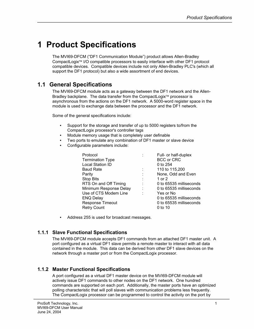
1 Product Specifications The MVI69-DFCM (“DF1 Communication Module”) product allows Allen-Bradley CompactLogix I/O compatible processors to easily interface with other DF1 protocol compatible devices. Compatible devices include not only Allen-Bradley PLC's (which all support the DF1 protocol) but also a wide assortment of end devices.
1.1 General Specifications The MVI69-DFCM module acts as a gateway between the DF1 network and the Allen-Bradley backplane. The data transfer from the CompactLogix processor is asynchronous from the actions on the DF1 network. A 5000-word register space in the module is used to exchange data between the processor and the DF1 network. Some of the general specifications include:
• Support for the storage and transfer of up to 5000 registers to/from the CompactLogix processor's controller tags
• Module memory usage that is completely user definable • Two ports to emulate any combination of DF1 master or slave device • Configurable parameters include:
Protocol : Full- or half-duplex Termination Type BCC or CRC Local Station ID 0 to 254 Baud Rate : 110 to 115,200 Parity : None, Odd and Even Stop Bits : 1 or 2 RTS On and Off Timing : 0 to 65535 milliseconds Minimum Response Delay : 0 to 65535 milliseconds Use of CTS Modem Line : Yes or No ENQ Delay 0 to 65535 milliseconds Response Timeout 0 to 65535 milliseconds Retry Count 0 to 10
• Address 255 is used for broadcast messages.
1.1.1 Slave Functional Specifications The MVI69-DFCM module accepts DF1 commands from an attached DF1 master unit. A port configured as a virtual DF1 slave permits a remote master to interact with all data contained in the module. This data can be derived from other DF1 slave devices on the network through a master port or from the CompactLogix processor.
1.1.2 Master Functional Specifications A port configured as a virtual DF1 master device on the MVI69-DFCM module will actively issue DF1 commands to other nodes on the DF1 network. One hundred commands are supported on each port. Additionally, the master ports have an optimized polling characteristic that will poll slaves with communication problems less frequently. The CompactLogix processor can be programmed to control the activity on the port by
ProSoft Technology, Inc. 1 MVI69-DFCM User Manual June 24, 2004
Product Specifications
actively selecting commands from the command list to execute or issuing commands directly from the ladder logic. The CompactLogix processor also has the ability to control the scanning of slaves on the port.
1.1.3 Physical This module is designed by ProSoft Technology and incorporates licensed technology from Allen-Bradley (CompactLogix backplane technology).
• CompactLogix Form Factor - Single Slot • Connections :
o RJ45 connectors for DF1 support of RS-232, RS-422 or RS-485 interfaces
o 1 – RJ45 RS-232 Configuration Tool Connector
1.1.4 CompactLogix Interface • Operation via simple ladder logic • Complete monitoring of module through RSLogix 5000 software • CompactLogix backplane interface via I/O access • All data related to the module is contained in a single controller tag with defined
objects to ease in the monitoring and interfacing with the module
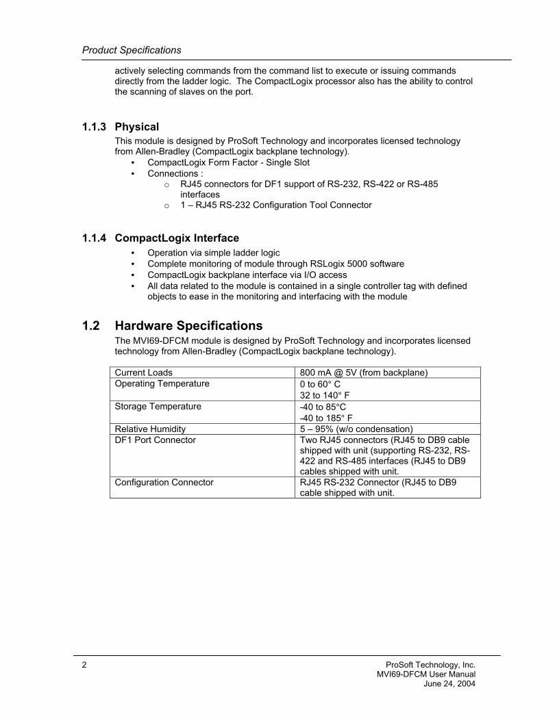
1.2 Hardware Specifications The MVI69-DFCM module is designed by ProSoft Technology and incorporates licensed technology from Allen-Bradley (CompactLogix backplane technology). Current Loads 800 mA @ 5V (from backplane) Operating Temperature 0 to 60° C
32 to 140° F Storage Temperature -40 to 85°C
-40 to 185° F Relative Humidity 5 – 95% (w/o condensation) DF1 Port Connector Two RJ45 connectors (RJ45 to DB9 cable
shipped with unit (supporting RS-232, RS-422 and RS-485 interfaces (RJ45 to DB9 cables shipped with unit.
Configuration Connector RJ45 RS-232 Connector (RJ45 to DB9 cable shipped with unit.
2 ProSoft Technology, Inc. MVI69-DFCM User Manual June 24, 2004
Functional Overview
2 Functional Overview This section provides a functional overview of the MVI69-DFCM module. A thorough understanding of the information contained in this document is required for successful implementation of the module in a user application. If you are not familiar with the data transfer and DF1 protocol operations, read this document before setting up the module.
2.1 General Concepts The following discussion covers several concepts that are key to understanding the operation of the MVI69-DFCM module.
2.1.1 Module Power Up • On power up the module begins performing the following logical functions: • Initialize hardware components
o Initialize CompactLogix backplane driver o Test and Clear all RAM o Initialize the serial communication ports
• Read module configuration from the Compact Flash • Initialize Module Register space • Enable Slave Driver on selected ports • Enable Master Driver on selected ports
Once this initialization procedure is complete, the module will begin communicating with other nodes on the network, depending on the configuration.
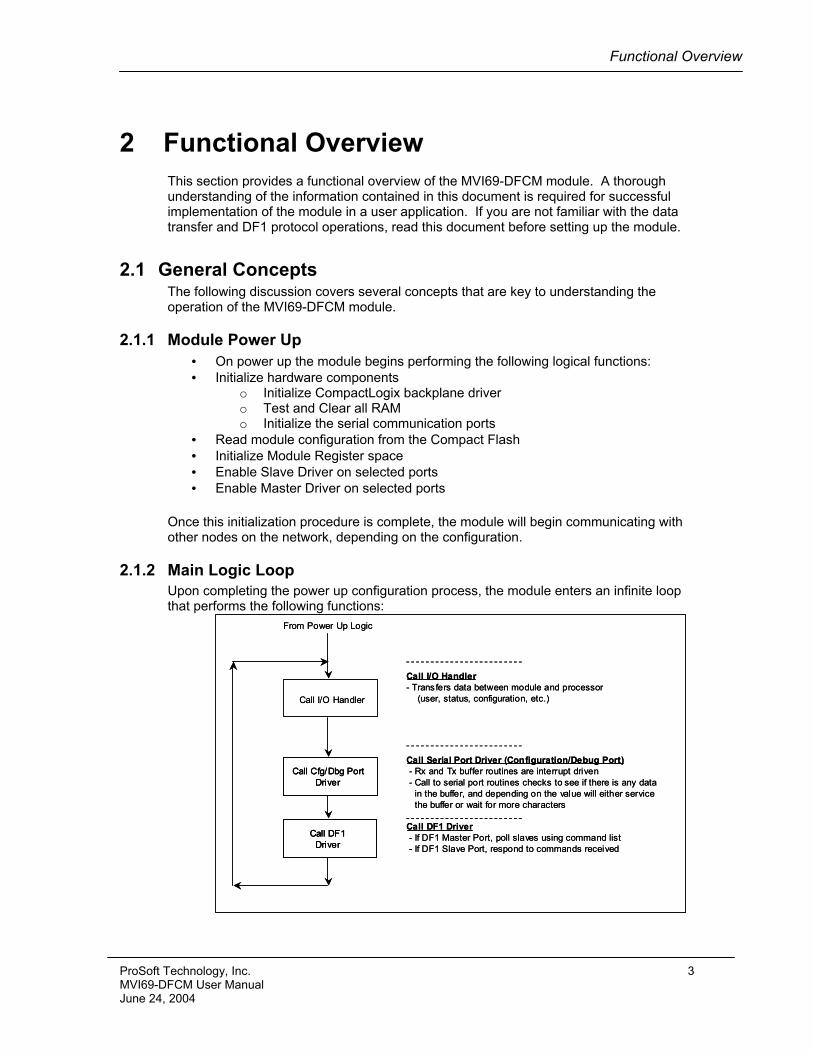
2.1.2 Main Logic Loop Upon completing the power up configuration process, the module enters an infinite loop that performs the following functions:
Call I/O Handler- Transfers data between module and processor
(user, status, configuration, etc.)
Call Serial Port Driver (Configuration/Debug Port)- Rx and Tx buffer routines are interrupt driven- Call to serial port routines checks to see if there is any data
in the buffer, and depending on the value will either servicethe buffer or wait for more characters
Call I/O Handler
Call Cfg/Dbg PortDriver
Call DF1 Driver- If DF1 Master Port, poll slaves using command list- If DF1 Slave Port, respond to commands received
From Power Up Logic
Call DF1Driver
Call I/O Handler- Transfers data between module and processor
(user, status, configuration, etc.)
Call Serial Port Driver (Configuration/Debug Port)- Rx and Tx buffer routines are interrupt driven- Call to serial port routines checks to see if there is any data
in the buffer, and depending on the value will either servicethe buffer or wait for more characters
Call I/O Handler
Call Cfg/Dbg PortDriver
Call Cfg/Dbg PortDriver
Call DF1 Driver- If DF1 Master Port, poll slaves using command list- If DF1 Slave Port, respond to commands received
From Power Up Logic
Call DF1Driver
Call DF1Driver
ProSoft Technology, Inc. 3 MVI69-DFCM User Manual June 24, 2004
Functional Overview
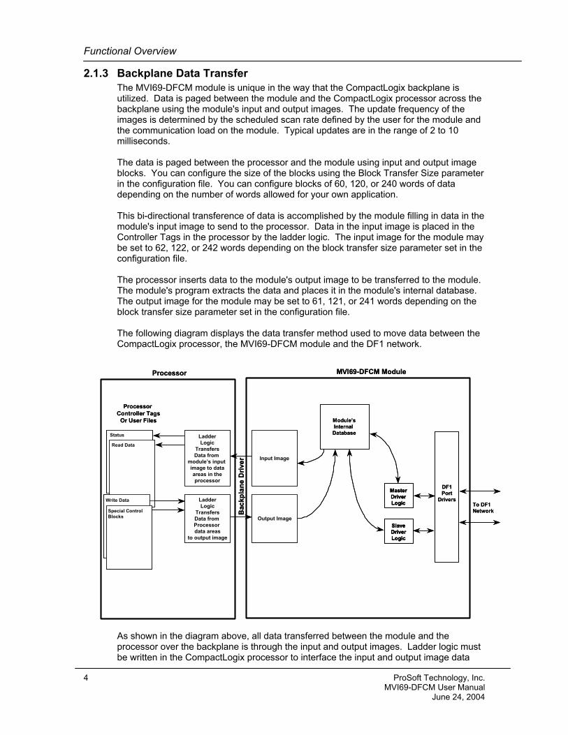
2.1.3 Backplane Data Transfer The MVI69-DFCM module is unique in the way that the CompactLogix backplane is utilized. Data is paged between the module and the CompactLogix processor across the backplane using the module's input and output images. The update frequency of the images is determined by the scheduled scan rate defined by the user for the module and the communication load on the module. Typical updates are in the range of 2 to 10 milliseconds. The data is paged between the processor and the module using input and output image blocks. You can configure the size of the blocks using the Block Transfer Size parameter in the configuration file. You can configure blocks of 60, 120, or 240 words of data depending on the number of words allowed for your own application. This bi-directional transference of data is accomplished by the module filling in data in the module's input image to send to the processor. Data in the input image is placed in the Controller Tags in the processor by the ladder logic. The input image for the module may be set to 62, 122, or 242 words depending on the block transfer size parameter set in the configuration file. The processor inserts data to the module's output image to be transferred to the module. The module's program extracts the data and places it in the module's internal database. The output image for the module may be set to 61, 121, or 241 words depending on the block transfer size parameter set in the configuration file. The following diagram displays the data transfer method used to move data between the CompactLogix processor, the MVI69-DFCM module and the DF1 network.
DF1Port
DriversMasterDriverLogic
SlaveDriverLogic
Module’sInternal Database
MVI69-DFCM Module
To DF1 Network
LadderLogic
TransfersData from
module’s input image to dataareas in theprocessor
Processor Controller Tags
Or User Files
Processor
LadderLogic
TransfersData from Processor data areas
to output image
Input Image
Output Image
Bac
kpla
ne D
river
Status
Read Data
Write Data
Special ControlBlocks
DF1Port
DriversMasterDriverLogic
MasterDriverLogic
SlaveDriverLogic
SlaveDriverLogic
Module’sInternal Database
MVI69-DFCM Module
To DF1 Network
LadderLogic
TransfersData from
module’s input image to dataareas in theprocessor
Processor Controller Tags
Or User Files
Processor
LadderLogic
TransfersData from Processor data areas
to output image
Input Image
Output Image
Bac
kpla
ne D
river
Status
Read Data
Write Data
Special ControlBlocks
As shown in the diagram above, all data transferred between the module and the processor over the backplane is through the input and output images. Ladder logic must be written in the CompactLogix processor to interface the input and output image data
4 ProSoft Technology, Inc. MVI69-DFCM User Manual June 24, 2004
Functional Overview
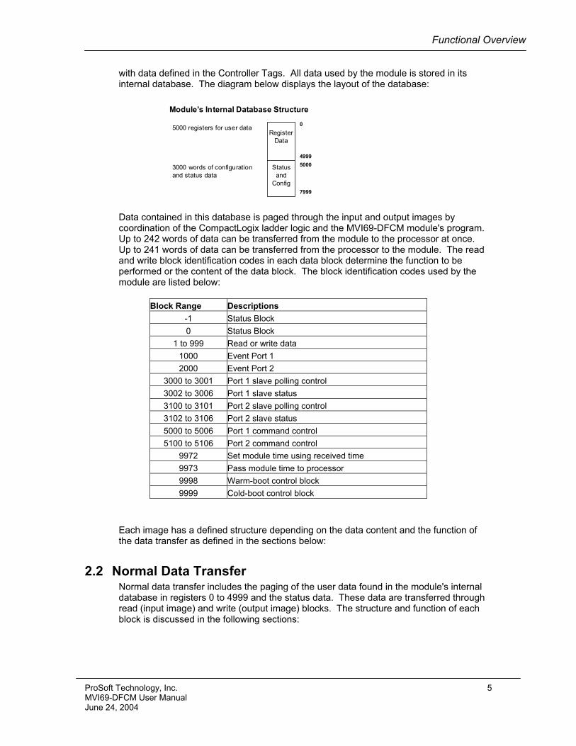
with data defined in the Controller Tags. All data used by the module is stored in its internal database. The diagram below displays the layout of the database:
5000 registers for user dataRegister
Data
Statusand
Config
Module’s Internal Database Structure
0
49995000
7999
3000 words of configurationand status data
Data contained in this database is paged through the input and output images by coordination of the CompactLogix ladder logic and the MVI69-DFCM module's program. Up to 242 words of data can be transferred from the module to the processor at once. Up to 241 words of data can be transferred from the processor to the module. The read and write block identification codes in each data block determine the function to be performed or the content of the data block. The block identification codes used by the module are listed below:
Block Range Descriptions -1 Status Block 0 Status Block
1 to 999 Read or write data 1000 Event Port 1 2000 Event Port 2
3000 to 3001 Port 1 slave polling control 3002 to 3006 Port 1 slave status 3100 to 3101 Port 2 slave polling control 3102 to 3106 Port 2 slave status 5000 to 5006 Port 1 command control 5100 to 5106 Port 2 command control
9972 Set module time using received time 9973 Pass module time to processor 9998 Warm-boot control block 9999 Cold-boot control block
Each image has a defined structure depending on the data content and the function of the data transfer as defined in the sections below:
2.2 Normal Data Transfer Normal data transfer includes the paging of the user data found in the module's internal database in registers 0 to 4999 and the status data. These data are transferred through read (input image) and write (output image) blocks. The structure and function of each block is discussed in the following sections:
ProSoft Technology, Inc. 5 MVI69-DFCM User Manual June 24, 2004
Functional Overview
2.2.1 Read Block These blocks of data are used to transfer information from the module to the CompactLogix processor. The structure of the input image used to transfer this data is shown below:
Offset Description Length
0 Read Block ID 1 1 Write Block ID 1
2 to (n+1) Read Data n where
n = 60, 120, or 240 depending on the Block Transfer Size parameter (refer to the configuration file).
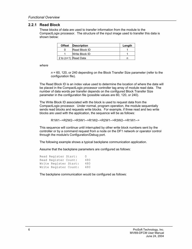
The Read Block ID is an index value used to determine the location of where the data will be placed in the CompactLogix processor controller tag array of module read data. The number of data words per transfer depends on the configured Block Transfer Size parameter in the configuration file (possible values are 60, 120, or 240). The Write Block ID associated with the block is used to request data from the CompactLogix processor. Under normal, program operation, the module sequentially sends read blocks and requests write blocks. For example, if three read and two write blocks are used with the application, the sequence will be as follows: R1W1-->R2W2-->R3W1-->R1W2-->R2W1-->R3W2-->R1W1--> This sequence will continue until interrupted by other write block numbers sent by the controller or by a command request from a node on the DF1 network or operator control through the module's Configuration/Debug port. The following example shows a typical backplane communication application. Assume that the backplane parameters are configured as follows: Read Register Start: 0 Read Register Count: 480 Write Register Start: 480 Write Register Count: 480 The backplane communication would be configured as follows:
6 ProSoft Technology, Inc. MVI69-DFCM User Manual June 24, 2004
Functional Overview
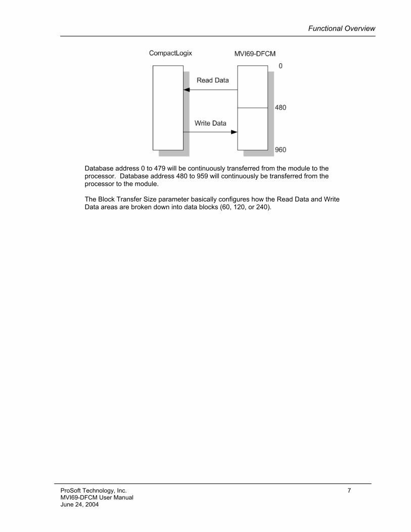
Database address 0 to 479 will be continuously transferred from the module to the processor. Database address 480 to 959 will continuously be transferred from the processor to the module. The Block Transfer Size parameter basically configures how the Read Data and Write Data areas are broken down into data blocks (60, 120, or 240).
ProSoft Technology, Inc. 7 MVI69-DFCM User Manual June 24, 2004
Functional Overview
If Block Transfer Size = 60:
If Block Transfer Size = 120:
8 ProSoft Technology, Inc. MVI69-DFCM User Manual June 24, 2004
Functional Overview
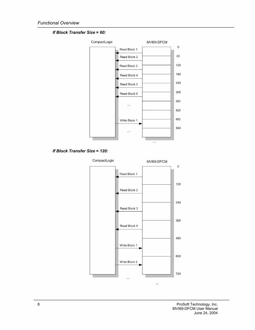
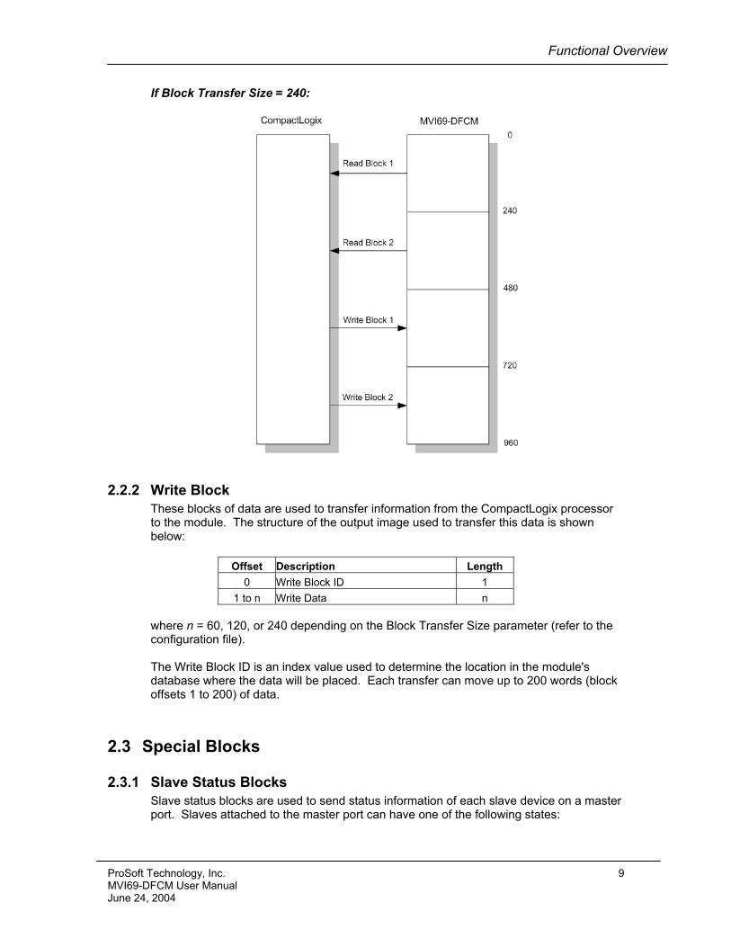
If Block Transfer Size = 240:
2.2.2 Write Block These blocks of data are used to transfer information from the CompactLogix processor to the module. The structure of the output image used to transfer this data is shown below:
Offset Description Length 0 Write Block ID 1
1 to n Write Data n where n = 60, 120, or 240 depending on the Block Transfer Size parameter (refer to the configuration file). The Write Block ID is an index value used to determine the location in the module's database where the data will be placed. Each transfer can move up to 200 words (block offsets 1 to 200) of data.
2.3 Special Blocks
2.3.1 Slave Status Blocks Slave status blocks are used to send status information of each slave device on a master port. Slaves attached to the master port can have one of the following states:
ProSoft Technology, Inc. 9 MVI69-DFCM User Manual June 24, 2004
Functional Overview
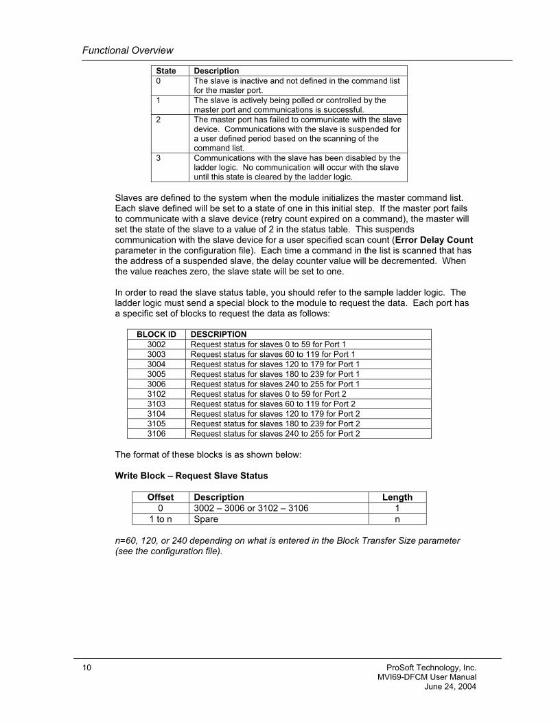
State Description 0 The slave is inactive and not defined in the command list
for the master port. 1 The slave is actively being polled or controlled by the
master port and communications is successful. 2 The master port has failed to communicate with the slave
device. Communications with the slave is suspended for a user defined period based on the scanning of the command list.
3 Communications with the slave has been disabled by the ladder logic. No communication will occur with the slave until this state is cleared by the ladder logic.
Slaves are defined to the system when the module initializes the master command list. Each slave defined will be set to a state of one in this initial step. If the master port fails to communicate with a slave device (retry count expired on a command), the master will set the state of the slave to a value of 2 in the status table. This suspends communication with the slave device for a user specified scan count (Error Delay Count parameter in the configuration file). Each time a command in the list is scanned that has the address of a suspended slave, the delay counter value will be decremented. When the value reaches zero, the slave state will be set to one. In order to read the slave status table, you should refer to the sample ladder logic. The ladder logic must send a special block to the module to request the data. Each port has a specific set of blocks to request the data as follows:
BLOCK ID DESCRIPTION 3002 Request status for slaves 0 to 59 for Port 1 3003 Request status for slaves 60 to 119 for Port 1 3004 Request status for slaves 120 to 179 for Port 1 3005 Request status for slaves 180 to 239 for Port 1 3006 Request status for slaves 240 to 255 for Port 1 3102 Request status for slaves 0 to 59 for Port 2 3103 Request status for slaves 60 to 119 for Port 2 3104 Request status for slaves 120 to 179 for Port 2 3105 Request status for slaves 180 to 239 for Port 2 3106 Request status for slaves 240 to 255 for Port 2
The format of these blocks is as shown below: Write Block – Request Slave Status
Offset Description Length 0 3002 – 3006 or 3102 – 3106 1
1 to n Spare n n=60, 120, or 240 depending on what is entered in the Block Transfer Size parameter (see the configuration file).
10 ProSoft Technology, Inc. MVI69-DFCM User Manual June 24, 2004
Functional Overview
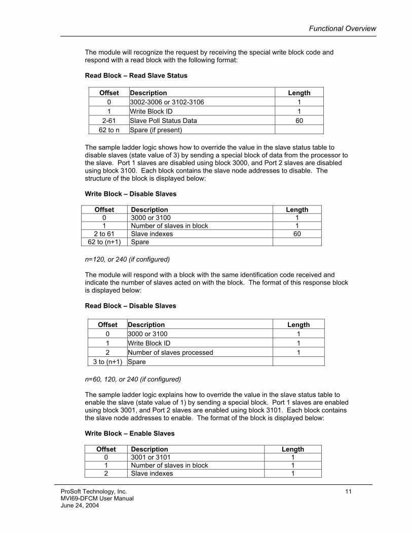
The module will recognize the request by receiving the special write block code and respond with a read block with the following format: Read Block – Read Slave Status
Offset Description Length 0 3002-3006 or 3102-3106 1 1 Write Block ID 1
2-61 Slave Poll Status Data 60 62 to n Spare (if present)
The sample ladder logic shows how to override the value in the slave status table to disable slaves (state value of 3) by sending a special block of data from the processor to the slave. Port 1 slaves are disabled using block 3000, and Port 2 slaves are disabled using block 3100. Each block contains the slave node addresses to disable. The structure of the block is displayed below: Write Block – Disable Slaves
Offset Description Length 0 3000 or 3100 1 1 Number of slaves in block 1
2 to 61 Slave indexes 60 62 to (n+1) Spare
n=120, or 240 (if configured) The module will respond with a block with the same identification code received and indicate the number of slaves acted on with the block. The format of this response block is displayed below: Read Block – Disable Slaves
Offset Description Length 0 3000 or 3100 1 1 Write Block ID 1 2 Number of slaves processed 1
3 to (n+1) Spare
n=60, 120, or 240 (if configured)
The sample ladder logic explains how to override the value in the slave status table to enable the slave (state value of 1) by sending a special block. Port 1 slaves are enabled using block 3001, and Port 2 slaves are enabled using block 3101. Each block contains the slave node addresses to enable. The format of the block is displayed below: Write Block – Enable Slaves
Offset Description Length 0 3001 or 3101 1 1 Number of slaves in block 1 2 Slave indexes 1
ProSoft Technology, Inc. 11 MVI69-DFCM User Manual June 24, 2004
Functional Overview
3 to n Spare
n=60, 120, or 240 depending on what is entered in the Block Transfer Size parameter (see the configuration file).
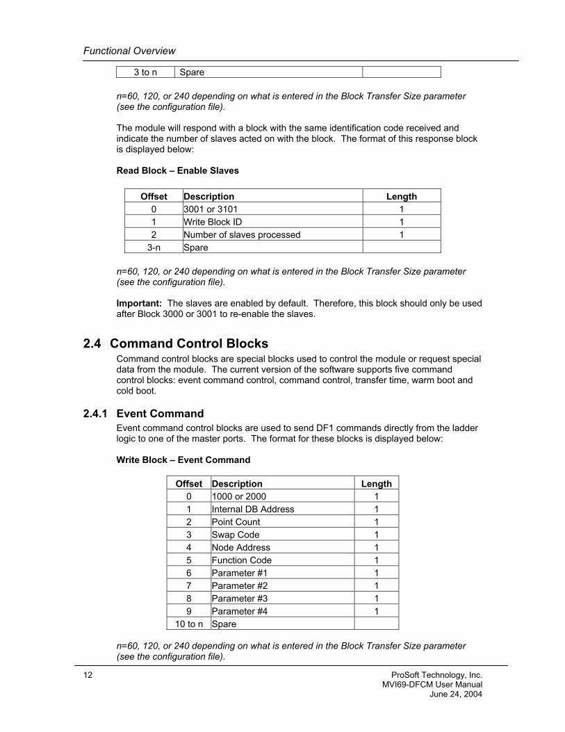
The module will respond with a block with the same identification code received and indicate the number of slaves acted on with the block. The format of this response block is displayed below: Read Block – Enable Slaves
Offset Description Length 0 3001 or 3101 1 1 Write Block ID 1 2 Number of slaves processed 1
3-n Spare
n=60, 120, or 240 depending on what is entered in the Block Transfer Size parameter (see the configuration file). Important: The slaves are enabled by default. Therefore, this block should only be used after Block 3000 or 3001 to re-enable the slaves.
2.4 Command Control Blocks Command control blocks are special blocks used to control the module or request special data from the module. The current version of the software supports five command control blocks: event command control, command control, transfer time, warm boot and cold boot.
2.4.1 Event Command Event command control blocks are used to send DF1 commands directly from the ladder logic to one of the master ports. The format for these blocks is displayed below: Write Block – Event Command
Offset Description Length 0 1000 or 2000 1 1 Internal DB Address 1 2 Point Count 1 3 Swap Code 1 4 Node Address 1 5 Function Code 1 6 Parameter #1 1 7 Parameter #2 1 8 Parameter #3 1 9 Parameter #4 1
10 to n Spare n=60, 120, or 240 depending on what is entered in the Block Transfer Size parameter (see the configuration file).
12 ProSoft Technology, Inc. MVI69-DFCM User Manual June 24, 2004
Functional Overview
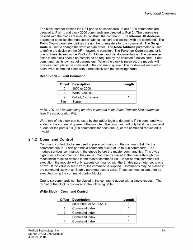
The block number defines the DF1 port to be considered. Block 1000 commands are directed to Port 1, and block 2000 commands are directed to Port 2. The parameters passed with the block are used to construct the command. The Internal DB Address parameter specifies the module's database location to associate with the command. The Point Count parameter defines the number of registers for the command. The Swap Code is used to change the word or byte order. The Node Address parameter is used to define the device on the DF1 network to consider. The Function Code parameter is one of those defined in the ProSoft DF1 Command Set documentation. The parameter fields in the block should be completed as required by the selected function code. Each command has its own set of parameters. When the block is received, the module will process it and place the command in the command queue. The module will respond to each event command block with a read block with the following format: Read Block – Event Command
Offset Description Length 0 1000 or 2000 1 1 Write Block ID 1 2 0=Fail, 1=Success 1
3 to n Spare
n=60, 120, or 240 depending on what is entered in the Block Transfer Size parameter (see the configuration file).
Word two of the block can be used by the ladder logic to determine if the command was added to the command queue of the module. The command will only fail if the command queue for the port is full (100 commands for each queue) or the command requested is invalid.
2.4.2 Command Control Command control blocks are used to place commands in the command list into the command queue. Each port has a command queue of up to 100 commands. The module services commands in the queue before the master command list. This gives high priority to commands in the queue. Commands placed in the queue through this mechanism must be defined in the master command list. Under normal command list execution, the module will only execute commands with the Enable parameter set to one or two. If the value is set to zero, the command is skipped. Commands may be placed in the command list with an Enable parameter set to zero. These commands can then be executed using the command control blocks. One to six commands can be placed in the command queue with a single request. The format of the block is displayed in the following table: Write Block – Command Control
Offset Description Length 0 5001-5006 or 5101-5106 1 1 Command index 1 2 Command index 1 3 Command index 1 4 Command index 1
ProSoft Technology, Inc. 13 MVI69-DFCM User Manual June 24, 2004
Functional Overview
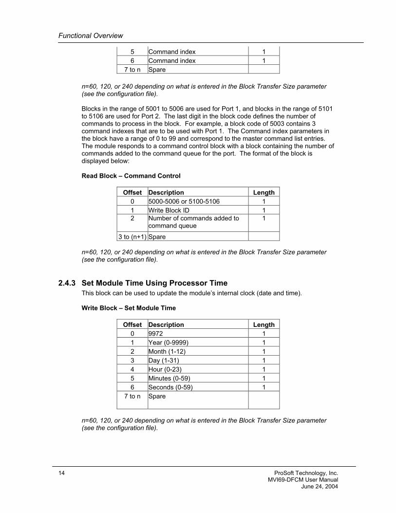
5 Command index 1 6 Command index 1
7 to n Spare
n=60, 120, or 240 depending on what is entered in the Block Transfer Size parameter (see the configuration file). Blocks in the range of 5001 to 5006 are used for Port 1, and blocks in the range of 5101 to 5106 are used for Port 2. The last digit in the block code defines the number of commands to process in the block. For example, a block code of 5003 contains 3 command indexes that are to be used with Port 1. The Command index parameters in the block have a range of 0 to 99 and correspond to the master command list entries. The module responds to a command control block with a block containing the number of commands added to the command queue for the port. The format of the block is displayed below: Read Block – Command Control
Offset Description Length 0 5000-5006 or 5100-5106 1 1 Write Block ID 1 2 Number of commands added to
command queue 1
3 to (n+1) Spare n=60, 120, or 240 depending on what is entered in the Block Transfer Size parameter (see the configuration file).
2.4.3 Set Module Time Using Processor Time This block can be used to update the module’s internal clock (date and time). Write Block – Set Module Time
Offset Description Length 0 9972 1 1 Year (0-9999) 1 2 Month (1-12) 1 3 Day (1-31) 1 4 Hour (0-23) 1 5 Minutes (0-59) 1 6 Seconds (0-59) 1
7 to n Spare
n=60, 120, or 240 depending on what is entered in the Block Transfer Size parameter (see the configuration file).
14 ProSoft Technology, Inc. MVI69-DFCM User Manual June 24, 2004
Functional Overview
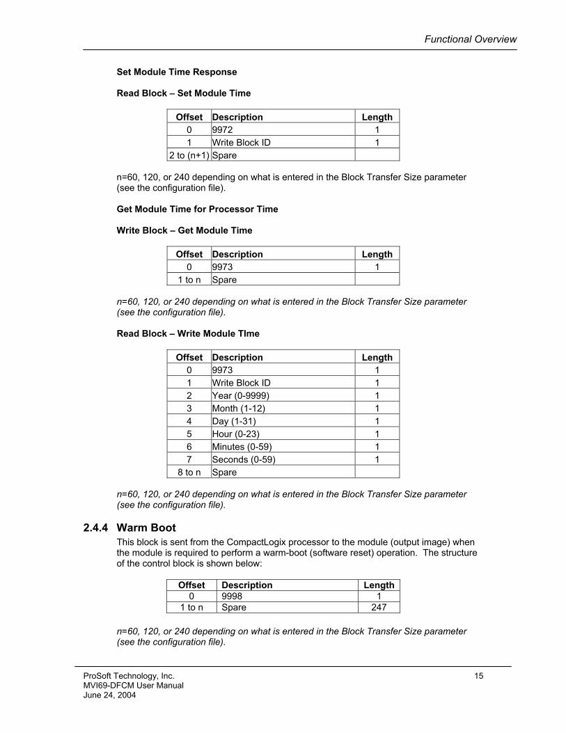
Set Module Time Response Read Block – Set Module Time
Offset Description Length 0 9972 1 1 Write Block ID 1
2 to (n+1) Spare n=60, 120, or 240 depending on what is entered in the Block Transfer Size parameter (see the configuration file). Get Module Time for Processor Time Write Block – Get Module Time
Offset Description Length 0 9973 1
1 to n Spare n=60, 120, or 240 depending on what is entered in the Block Transfer Size parameter (see the configuration file). Read Block – Write Module TIme
Offset Description Length 0 9973 1 1 Write Block ID 1 2 Year (0-9999) 1 3 Month (1-12) 1 4 Day (1-31) 1 5 Hour (0-23) 1 6 Minutes (0-59) 1 7 Seconds (0-59) 1
8 to n Spare n=60, 120, or 240 depending on what is entered in the Block Transfer Size parameter (see the configuration file).
2.4.4 Warm Boot This block is sent from the CompactLogix processor to the module (output image) when the module is required to perform a warm-boot (software reset) operation. The structure of the control block is shown below:
Offset Description Length 0 9998 1
1 to n Spare 247
n=60, 120, or 240 depending on what is entered in the Block Transfer Size parameter (see the configuration file).
ProSoft Technology, Inc. 15 MVI69-DFCM User Manual June 24, 2004
Functional Overview
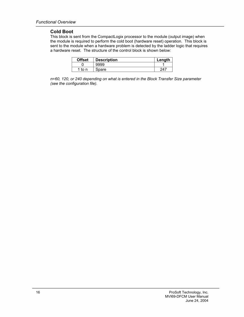
Cold Boot This block is sent from the CompactLogix processor to the module (output image) when the module is required to perform the cold boot (hardware reset) operation. This block is sent to the module when a hardware problem is detected by the ladder logic that requires a hardware reset. The structure of the control block is shown below:
Offset Description Length 0 9999 1
1 to n Spare 247 n=60, 120, or 240 depending on what is entered in the Block Transfer Size parameter (see the configuration file).
16 ProSoft Technology, Inc. MVI69-DFCM User Manual June 24, 2004
Functional Overview
2.5 Data Flow between MVI69-DFCM Module and CompactLogix Processor
The following discussion details the flow of data between the two pieces of hardware (CompactLogix processor and MVI69-DFCM module) and other nodes on the DF1 network under the module’s different operating modes. Each port on the module is configured to emulate a DF1 master device or a DF1 slave device. The operation of each port is dependent on this configuration. The sections below discuss the operation of each mode.
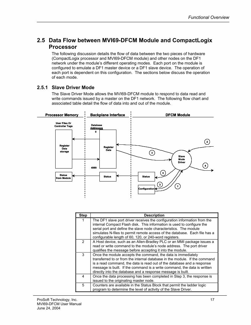
2.5.1 Slave Driver Mode The Slave Driver Mode allows the MVI69-DFCM module to respond to data read and write commands issued by a master on the DF1 network. The following flow chart and associated table detail the flow of data into and out of the module.
0
4999
DatabaseAddresses
User Files OrController Tags
SlaveModeDriver
StatusStatusfrom Module
RegisterData
storage
RegisterData
Processor Memory DFCM ModuleBackplane Interface
Configuration
Status
4
2
3
5
13
0
4999
DatabaseAddresses
User Files OrController Tags
SlaveModeDriver
StatusStatusfrom Module
RegisterData
storage
RegisterData
Processor Memory DFCM ModuleBackplane Interface
Configuration
Status
4
2
3
5
13
Step Description 1 The DF1 slave port driver receives the configuration information from the
internal Compact Flash disk. This information is used to configure the serial port and define the slave node characteristics. The module simulates N-files to permit remote access of the database. Each file has a configurable length of 60, 120, or 240-word registers.
2 A Host device, such as an Allen-Bradley PLC or an MMI package issues a read or write command to the module’s node address. The port driver qualifies the message before accepting it into the module.
3 Once the module accepts the command, the data is immediately transferred to or from the internal database in the module. If the command is a read command, the data is read out of the database and a response message is built. If the command is a write command, the data is written directly into the database and a response message is built.
4 Once the data processing has been completed in Step 3, the response is issued to the originating master node.
5 Counters are available in the Status Block that permit the ladder logic program to determine the level of activity of the Slave Driver.
ProSoft Technology, Inc. 17 MVI69-DFCM User Manual June 24, 2004

Functional Overview
Review the Module Set Up section for a complete list of the parameters that must be defined for a slave port. The slave driver supports the following DF1 command set:
Basic Command Set Functions Command Function Definition
Supp
orte
d in
Sl
ave
0x00 N/A Protected Write X 0x01 N/A Unprotected Read X 0x02 N/A Protected Bit Write X 0x05 N/A Unprotected Bit Write X 0x06 0x00 Echo Request X 0x06 0x03 Status Request X 0x08 N/A Unprotected Write X
PLC-5 Command Set Functions
Command Function Definition
Supp
orte
d in
Sl
ave
0x0F 0x00 Word Range Write (Binary Address)
X
0x0F 0x01 Word Range Read (Binary Address)
X
0x0F 0x26 Read-Modify-Write (Binary Address)
0x0F 0x00 Word Range Write (ASCII Address)
X
0x0F 0x01 Word Range Read (ASCII Address)
X
0x0F 0x26 Read-Modify-Write (ASCII Address)
18 ProSoft Technology, Inc. MVI69-DFCM User Manual June 24, 2004
Functional Overview
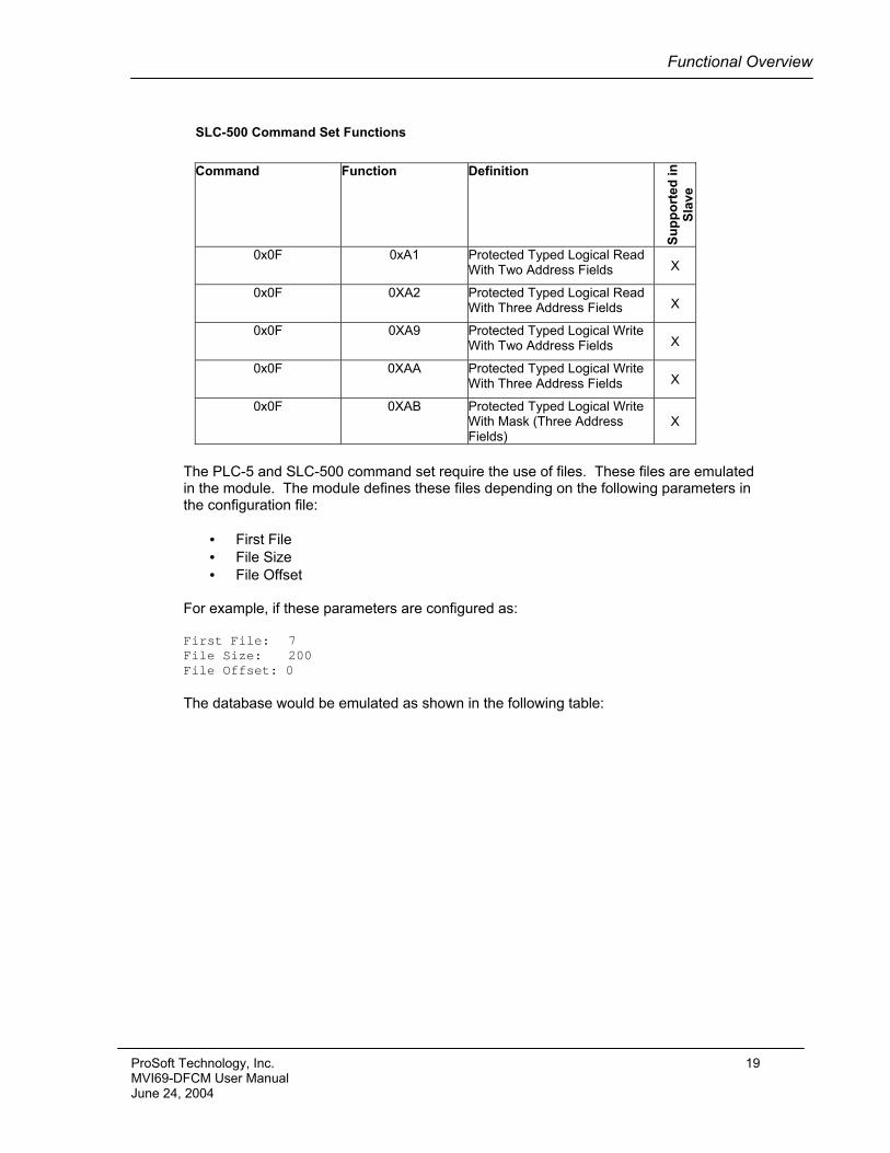
SLC-500 Command Set Functions
Command Function Definition
Supp
orte
d in
Sl
ave
0x0F 0xA1 Protected Typed Logical Read With Two Address Fields X
0x0F 0XA2 Protected Typed Logical Read With Three Address Fields X
0x0F 0XA9 Protected Typed Logical Write With Two Address Fields X
0x0F 0XAA Protected Typed Logical Write With Three Address Fields X
0x0F 0XAB Protected Typed Logical Write With Mask (Three Address Fields)
X
The PLC-5 and SLC-500 command set require the use of files. These files are emulated in the module. The module defines these files depending on the following parameters in the configuration file:
• First File • File Size • File Offset
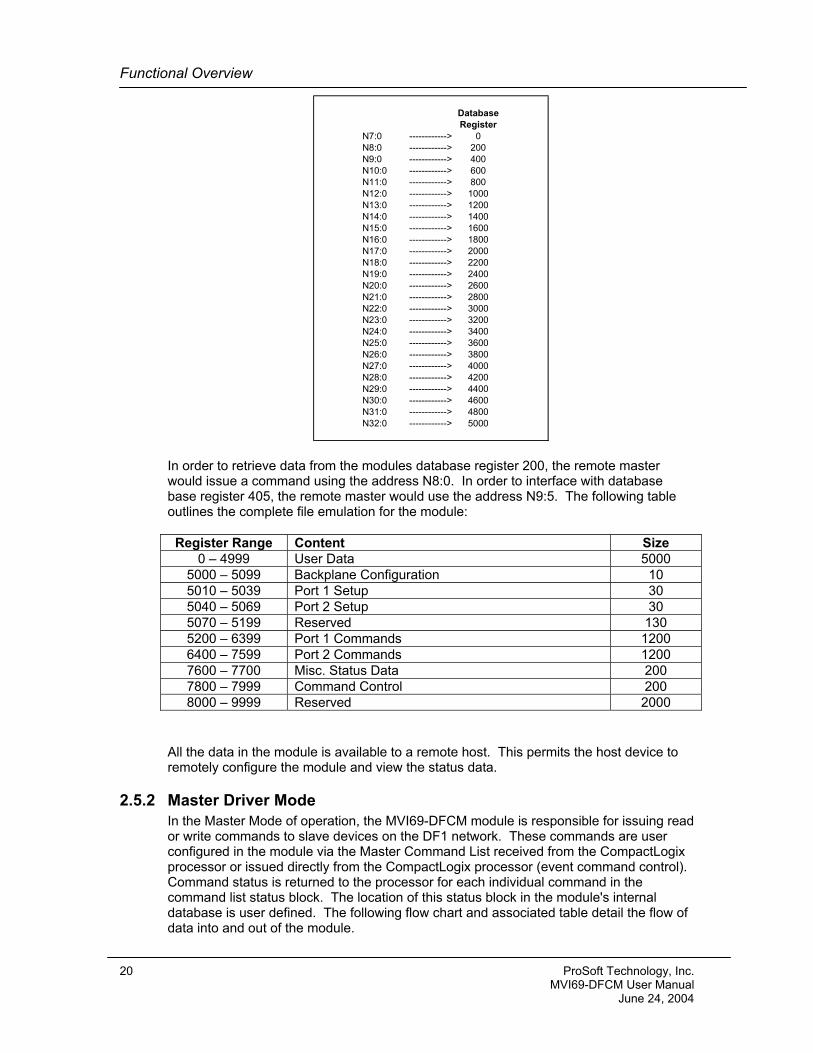
For example, if these parameters are configured as: First File: 7 File Size: 200 File Offset: 0 The database would be emulated as shown in the following table:
ProSoft Technology, Inc. 19 MVI69-DFCM User Manual June 24, 2004
Functional Overview
DatabaseRegister
N7:0 ------------> 0N8:0 ------------> 200N9:0 ------------> 400N10:0 ------------> 600N11:0 ------------> 800N12:0 ------------> 1000N13:0 ------------> 1200N14:0 ------------> 1400N15:0 ------------> 1600N16:0 ------------> 1800N17:0 ------------> 2000N18:0 ------------> 2200N19:0 ------------> 2400N20:0 ------------> 2600N21:0 ------------> 2800N22:0 ------------> 3000N23:0 ------------> 3200N24:0 ------------> 3400N25:0 ------------> 3600N26:0 ------------> 3800N27:0 ------------> 4000N28:0 ------------> 4200N29:0 ------------> 4400N30:0 ------------> 4600N31:0 ------------> 4800N32:0 ------------> 5000
In order to retrieve data from the modules database register 200, the remote master would issue a command using the address N8:0. In order to interface with database base register 405, the remote master would use the address N9:5. The following table outlines the complete file emulation for the module:
Register Range Content Size 0 – 4999 User Data 5000
5000 – 5099 Backplane Configuration 10 5010 – 5039 Port 1 Setup 30 5040 – 5069 Port 2 Setup 30 5070 – 5199 Reserved 130 5200 – 6399 Port 1 Commands 1200 6400 – 7599 Port 2 Commands 1200 7600 – 7700 Misc. Status Data 200 7800 – 7999 Command Control 200 8000 – 9999 Reserved 2000
All the data in the module is available to a remote host. This permits the host device to remotely configure the module and view the status data.
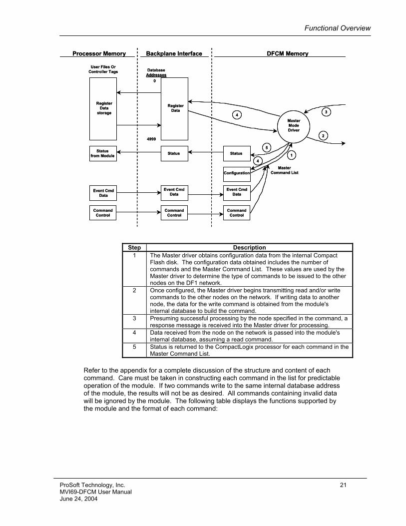
2.5.2 Master Driver Mode In the Master Mode of operation, the MVI69-DFCM module is responsible for issuing read or write commands to slave devices on the DF1 network. These commands are user configured in the module via the Master Command List received from the CompactLogix processor or issued directly from the CompactLogix processor (event command control). Command status is returned to the processor for each individual command in the command list status block. The location of this status block in the module's internal database is user defined. The following flow chart and associated table detail the flow of data into and out of the module.
20 ProSoft Technology, Inc. MVI69-DFCM User Manual June 24, 2004
Functional Overview
MasterModeDriver
DFCM Memory
ConfigurationMaster
Command List
Status
3
1
2
4
5
0
4999
DatabaseAddresses
User Files OrController Tags
StatusStatusfrom Module
RegisterData
storage
RegisterData
Processor Memory Backplane Interface
Event CmdData
Event CmdData
Event CmdData
CommandControl
CommandControl
CommandControl
4
Step Description 1 The Master driver obtains configuration data from the internal Compact
Flash disk. The configuration data obtained includes the number of commands and the Master Command List. These values are used by the Master driver to determine the type of commands to be issued to the other nodes on the DF1 network.
2 Once configured, the Master driver begins transmitting read and/or write commands to the other nodes on the network. If writing data to another node, the data for the write command is obtained from the module's internal database to build the command.
3 Presuming successful processing by the node specified in the command, a response message is received into the Master driver for processing.
4 Data received from the node on the network is passed into the module's internal database, assuming a read command.
5 Status is returned to the CompactLogix processor for each command in the Master Command List.
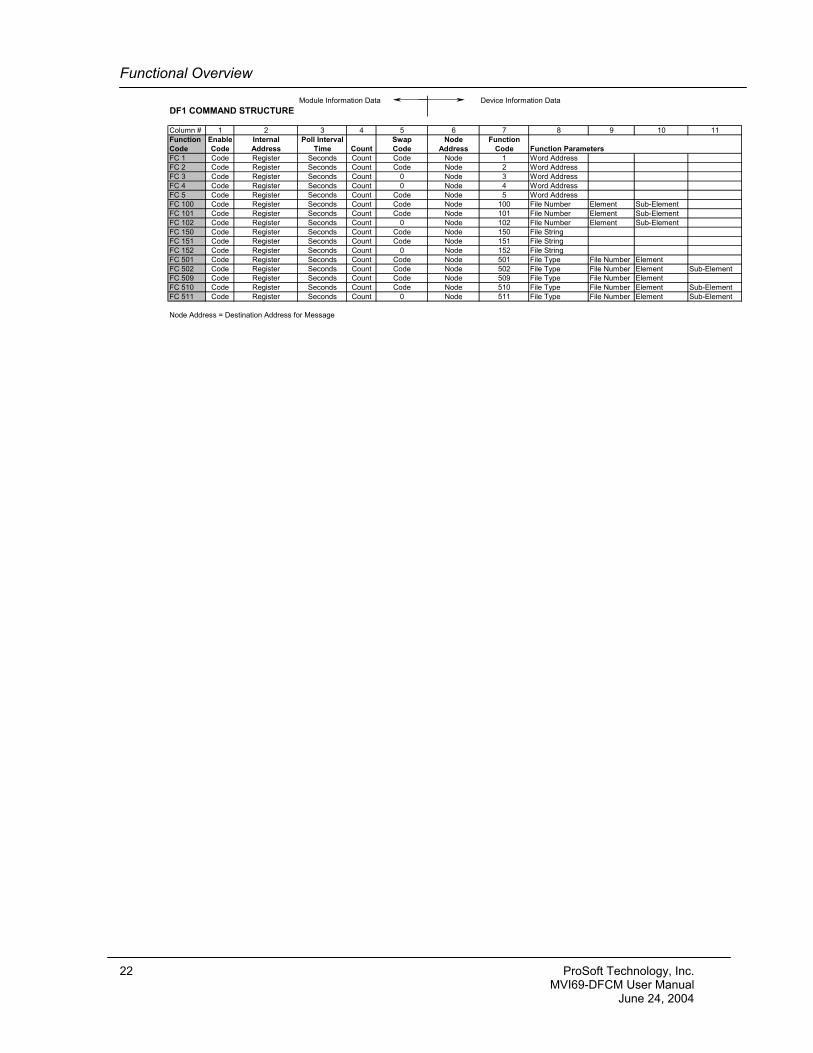
Refer to the appendix for a complete discussion of the structure and content of each command. Care must be taken in constructing each command in the list for predictable operation of the module. If two commands write to the same internal database address of the module, the results will not be as desired. All commands containing invalid data will be ignored by the module. The following table displays the functions supported by the module and the format of each command:
ProSoft Technology, Inc. 21 MVI69-DFCM User Manual June 24, 2004
Functional Overview
Module Information Data Device Information DataDF1 COMMAND STRUCTURE
Column # 1 2 3 4 5 6 7 8 9 10 11Function Enable Internal Poll Interval Swap Node FunctionCode Code Address Time Count Code Address Code Function ParametersFC 1 Code Register Seconds Count Code Node 1 Word AddressFC 2 Code Register Seconds Count Code Node 2 Word AddressFC 3 Code Register Seconds Count 0 Node 3 Word AddressFC 4 Code Register Seconds Count 0 Node 4 Word AddressFC 5 Code Register Seconds Count Code Node 5 Word AddressFC 100 Code Register Seconds Count Code Node 100 File Number Element Sub-ElementFC 101 Code Register Seconds Count Code Node 101 File Number Element Sub-ElementFC 102 Code Register Seconds Count 0 Node 102 File Number Element Sub-ElementFC 150 Code Register Seconds Count Code Node 150 File StringFC 151 Code Register Seconds Count Code Node 151 File StringFC 152 Code Register Seconds Count 0 Node 152 File StringFC 501 Code Register Seconds Count Code Node 501 File Type File Number ElementFC 502 Code Register Seconds Count Code Node 502 File Type File Number Element Sub-ElementFC 509 Code Register Seconds Count Code Node 509 File Type File Number ElementFC 510 Code Register Seconds Count Code Node 510 File Type File Number Element Sub-ElementFC 511 Code Register Seconds Count 0 Node 511 File Type File Number Element Sub-Element
Node Address = Destination Address for Message
22 ProSoft Technology, Inc. MVI69-DFCM User Manual June 24, 2004
Module Configuration
3 Module Configuration
3.1 Power Up On power up, the module enters into a logical loop waiting to receive configuration data from the processor. Upon receipt, the module will begin execution of the command list if it is present.
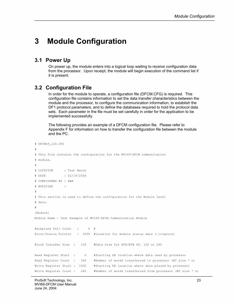
3.2 Configuration File In order for the module to operate, a configuration file (DFCM.CFG) is required. This configuration file contains information to set the data transfer characteristics between the module and the processor, to configure the communication information, to establish the DF1 protocol parameters, and to define the databases required to hold the protocol data sets. Each parameter in the file must be set carefully in order for the application to be implemented successfully. The following provides an example of a DFCM configuration file. Please refer to Appendix F for information on how to transfer the configuration file between the module and the PC.
# DFCM69_120.CFG
#
# This file contains the configuration for the MVI69-DFCM communication
# module.
#
# LOCATION : Test Bench
# DATE : 02/19/2004
# CONFIGURED BY : RAR
# MODIFIED :
#
# This section is used to define the configuration for the Module level
# data.
#
[Module]
Module Name : Test Example of MVI69-DFCM Communication Module
Backplane Fail Count : 0 #
Error/Status Pointer : 2000 #Location for module status data (-1=ignore)
Block Transfer Size : 120 #Data size for BTR/BTW 60, 120 or 240
Read Register Start : 0 #Starting DB location where data read by processor
Read Register Count : 360 #Number of words transferred to processor (BT size * n)
Write Register Start : 1000 #Starting DB location where data placed by processor
Write Register Count : 240 #Number of words transferred from processor (BT size * n)
ProSoft Technology, Inc. 23 MVI69-DFCM User Manual June 24, 2004
Module Configuration
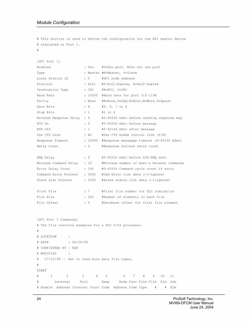
# This section is used to define the configuration for the DF1 master device
# simulated on Port 1.
#
[DF1 Port 1]
Enabled : Yes #Y=Use port, N=Do not use port
Type : Master #M=Master, S=Slave
Local Station ID : 0 #DF1 node address
Protocol : Full #F=Full-Duplex, H=Half-Duplex
Termination Type : CRC #B=BCC, C=CRC
Baud Rate : 19200 #Baud rate for port 110-115K
Parity : None #N=None,O=Odd,E=Even,M=Mark,S=Space
Data Bits : 8 #5, 6, 7 or 8
Stop Bits : 1 #1 or 2
Minimum Response Delay : 0 #0-65535 mSec before sending response msg
RTS On : 0 #0-65536 mSec before message
RTS Off : 1 #0-65536 mSec after message
Use CTS Line : No #Use CTS modem control line (Y/N)
Response Timeout : 15000 #Response messgage timeout (0-65535 mSec)
Retry Count : 2 #Response failure retry count
ENQ Delay : 0 #0-65535 mSec before DLE-ENQ sent
Minimum Command Delay : 10 #Minimum number of msec's between commands
Error Delay Count : 100 #0-65535 Command cycle count if error
Command Error Pointer : 3000 #Cmd Error list data (-1=ignore)
Slave List Pointer : 3100 #Slave status list data (-1=ignore)
First File : 7 #First file number for SLC simulation
File Size : 200 #Number of elements in each file
File Offset : 0 #Database offset for first file element
[DF1 Port 1 Commands]
# The file contains examples for a SLC 5/03 processor.
#
# LOCATION :
# DATE : 06/24/99
# CONFIGURED BY : RAR
# MODIFIED :
# 07/23/99 -- Set to read more data file types.
#
START
# 1 2 3 4 5 6 7 8 9 10 11
# Internal Poll Swap Node Func File File Elm Sub
# Enable Address Interval Count Code Address Code Type # # Elm
24 ProSoft Technology, Inc. MVI69-DFCM User Manual June 24, 2004
Module Configuration
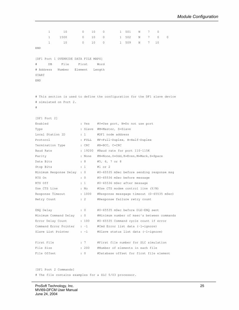
1 10 0 10 0 1 501 N 7 0
1 1500 0 10 0 1 502 N 7 0 0
1 10 0 10 0 1 509 N 7 10
END
[DF1 Port 1 OVERRIDE DATA FILE MAPS]
# DB File First Word
# Address Number Element Length
START
END
# This section is used to define the configuration for the DF1 slave device
# simulated on Port 2.
#
[DF1 Port 2]
Enabled : Yes #Y=Use port, N=Do not use port
Type : Slave #M=Master, S=Slave
Local Station ID : 1 #DF1 node address
Protocol : FULL #F=Full-Duplex, H=Half-Duplex
Termination Type : CRC #B=BCC, C=CRC
Baud Rate : 19200 #Baud rate for port 110-115K
Parity : None #N=None,O=Odd,E=Even,M=Mark,S=Space
Data Bits : 8 #5, 6, 7 or 8
Stop Bits : 1 #1 or 2
Minimum Response Delay : 0 #0-65535 mSec before sending response msg
RTS On : 0 #0-65536 mSec before message
RTS Off : 1 #0-65536 mSec after message
Use CTS Line : No #Use CTS modem control line (Y/N)
Response Timeout : 1000 #Response messgage timeout (0-65535 mSec)
Retry Count : 2 #Response failure retry count
ENQ Delay : 0 #0-65535 mSec before DLE-ENQ sent
Minimum Command Delay : 0 #Minimum number of msec's between commands
Error Delay Count : 100 #0-65535 Command cycle count if error
Command Error Pointer : -1 #Cmd Error list data (-1=ignore)
Slave List Pointer : -1 #Slave status list data (-1=ignore)
First File : 7 #First file number for SLC simulation
File Size : 200 #Number of elements in each file
File Offset : 0 #Database offset for first file element
[DF1 Port 2 Commands]
# The file contains examples for a SLC 5/03 processor.
ProSoft Technology, Inc. 25 MVI69-DFCM User Manual June 24, 2004
Module Configuration
#
# LOCATION :
# DATE : 06/24/99
# CONFIGURED BY : RAR
# MODIFIED :
# 07/23/99 -- Set to read more data file types.
#
START
# 1 2 3 4 5 6 7 8 9 10 11
# Internal Poll Swap Node Func File File Elm Sub
# Enable Address Interval Count Code Address Code Type # # Elm
END
[DF1 Port 2 OVERRIDE DATA FILE MAPS]
# DB File First Word
# Address Number Element Length
START
3500 200 0 100
3600 230 0 200
END
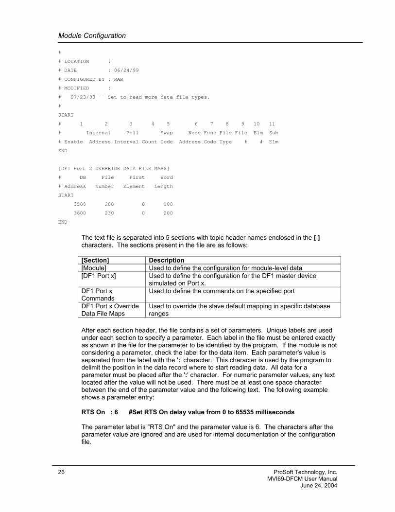
The text file is separated into 5 sections with topic header names enclosed in the [ ] characters. The sections present in the file are as follows: [Section] Description [Module] Used to define the configuration for module-level data [DF1 Port x] Used to define the configuration for the DF1 master device
simulated on Port x. DF1 Port x Commands
Used to define the commands on the specified port
DF1 Port x Override Data File Maps
Used to override the slave default mapping in specific database ranges
After each section header, the file contains a set of parameters. Unique labels are used under each section to specify a parameter. Each label in the file must be entered exactly as shown in the file for the parameter to be identified by the program. If the module is not considering a parameter, check the label for the data item. Each parameter's value is separated from the label with the ':' character. This character is used by the program to delimit the position in the data record where to start reading data. All data for a parameter must be placed after the ':' character. For numeric parameter values, any text located after the value will not be used. There must be at least one space character between the end of the parameter value and the following text. The following example shows a parameter entry: RTS On : 6 #Set RTS On delay value from 0 to 65535 milliseconds The parameter label is "RTS On" and the parameter value is 6. The characters after the parameter value are ignored and are used for internal documentation of the configuration file.
26 ProSoft Technology, Inc. MVI69-DFCM User Manual June 24, 2004
Module Configuration
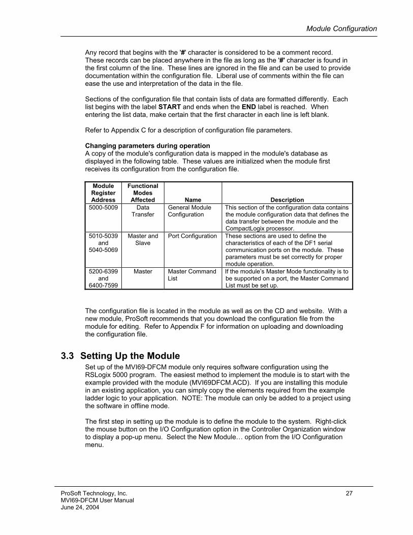
Any record that begins with the '#' character is considered to be a comment record. These records can be placed anywhere in the file as long as the '#' character is found in the first column of the line. These lines are ignored in the file and can be used to provide documentation within the configuration file. Liberal use of comments within the file can ease the use and interpretation of the data in the file. Sections of the configuration file that contain lists of data are formatted differently. Each list begins with the label START and ends when the END label is reached. When entering the list data, make certain that the first character in each line is left blank. Refer to Appendix C for a description of configuration file parameters. Changing parameters during operation A copy of the module's configuration data is mapped in the module's database as displayed in the following table. These values are initialized when the module first receives its configuration from the configuration file.
Module Register Address
Functional Modes
Affected
Name
Description 5000-5009 Data
Transfer
General Module Configuration
This section of the configuration data contains the module configuration data that defines the data transfer between the module and the CompactLogix processor.
5010-5039 and
5040-5069
Master and Slave
Port Configuration These sections are used to define the characteristics of each of the DF1 serial communication ports on the module. These parameters must be set correctly for proper module operation.
5200-6399 and
6400-7599
Master Master Command List
If the module’s Master Mode functionality is to be supported on a port, the Master Command List must be set up.
The configuration file is located in the module as well as on the CD and website. With a new module, ProSoft recommends that you download the configuration file from the module for editing. Refer to Appendix F for information on uploading and downloading the configuration file.
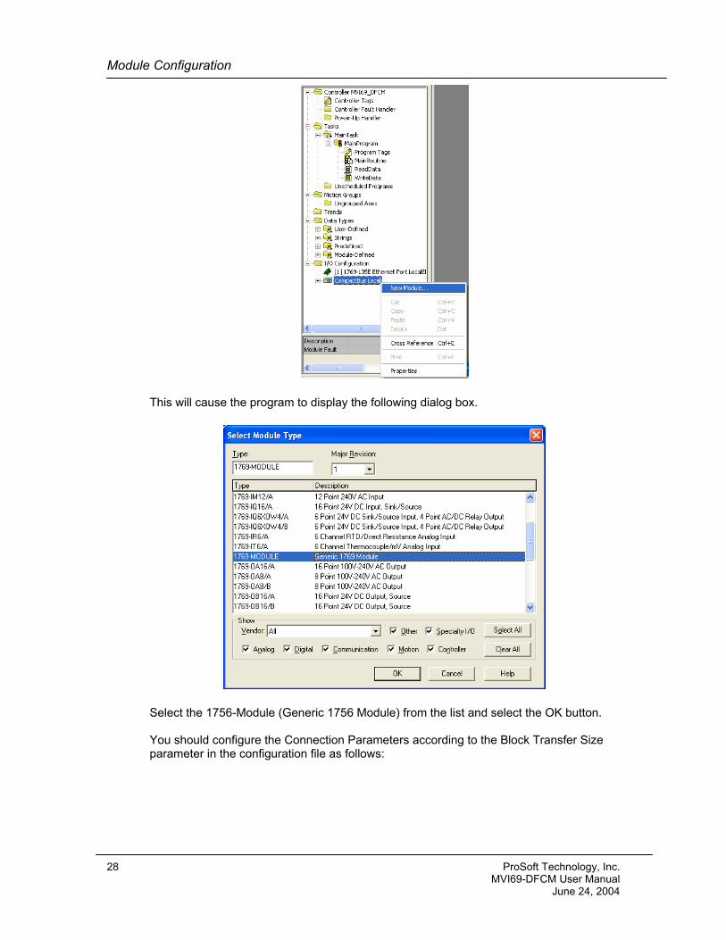
3.3 Setting Up the Module Set up of the MVI69-DFCM module only requires software configuration using the RSLogix 5000 program. The easiest method to implement the module is to start with the example provided with the module (MVI69DFCM.ACD). If you are installing this module in an existing application, you can simply copy the elements required from the example ladder logic to your application. NOTE: The module can only be added to a project using the software in offline mode. The first step in setting up the module is to define the module to the system. Right-click the mouse button on the I/O Configuration option in the Controller Organization window to display a pop-up menu. Select the New Module… option from the I/O Configuration menu.
ProSoft Technology, Inc. 27 MVI69-DFCM User Manual June 24, 2004
Module Configuration
This will cause the program to display the following dialog box.
Select the 1756-Module (Generic 1756 Module) from the list and select the OK button. You should configure the Connection Parameters according to the Block Transfer Size parameter in the configuration file as follows:
28 ProSoft Technology, Inc. MVI69-DFCM User Manual June 24, 2004
Module Configuration
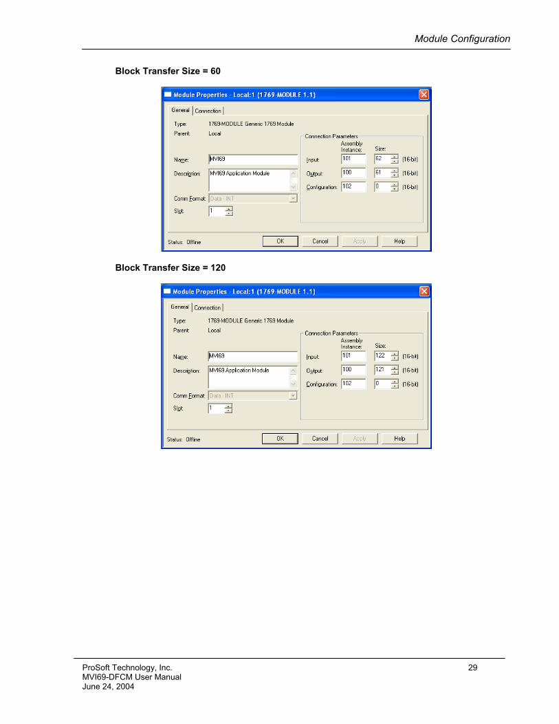
Block Transfer Size = 60
Block Transfer Size = 120
ProSoft Technology, Inc. 29 MVI69-DFCM User Manual June 24, 2004
Module Configuration
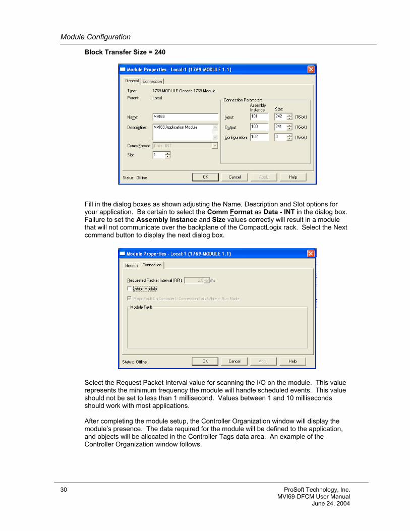
Block Transfer Size = 240
Fill in the dialog boxes as shown adjusting the Name, Description and Slot options for your application. Be certain to select the Comm Format as Data - INT in the dialog box. Failure to set the Assembly Instance and Size values correctly will result in a module that will not communicate over the backplane of the CompactLogix rack. Select the Next command button to display the next dialog box.
Select the Request Packet Interval value for scanning the I/O on the module. This value represents the minimum frequency the module will handle scheduled events. This value should not be set to less than 1 millisecond. Values between 1 and 10 milliseconds should work with most applications. After completing the module setup, the Controller Organization window will display the module’s presence. The data required for the module will be defined to the application, and objects will be allocated in the Controller Tags data area. An example of the Controller Organization window follows.
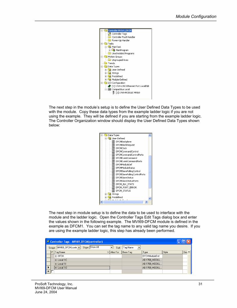
30 ProSoft Technology, Inc. MVI69-DFCM User Manual June 24, 2004
Module Configuration
The next step in the module’s setup is to define the User Defined Data Types to be used with the module. Copy these data types from the example ladder logic if you are not using the example. They will be defined if you are starting from the example ladder logic. The Controller Organization window should display the User Defined Data Types shown below:
The next step in module setup is to define the data to be used to interface with the module and the ladder logic. Open the Controller Tags Edit Tags dialog box and enter the values shown in the following example. The MVI69-DFCM module is defined in the example as DFCM1. You can set the tag name to any valid tag name you desire. If you are using the example ladder logic, this step has already been performed.
ProSoft Technology, Inc. 31 MVI69-DFCM User Manual June 24, 2004
Module Configuration
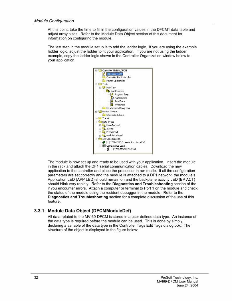
At this point, take the time to fill in the configuration values in the DFCM1 data table and adjust array sizes. Refer to the Module Data Object section of this document for information on configuring the module. The last step in the module setup is to add the ladder logic. If you are using the example ladder logic, adjust the ladder to fit your application. If you are not using the ladder example, copy the ladder logic shown in the Controller Organization window below to your application.
The module is now set up and ready to be used with your application. Insert the module in the rack and attach the DF1 serial communication cables. Download the new application to the controller and place the processor in run mode. If all the configuration parameters are set correctly and the module is attached to a DF1 network, the module’s Application LED (APP LED) should remain on and the backplane activity LED (BP ACT) should blink very rapidly. Refer to the Diagnostics and Troubleshooting section of the if you encounter errors. Attach a computer or terminal to Port 1 on the module and check the status of the module using the resident debugger in the module. Refer to the Diagnostics and Troubleshooting section for a complete discussion of the use of this feature.
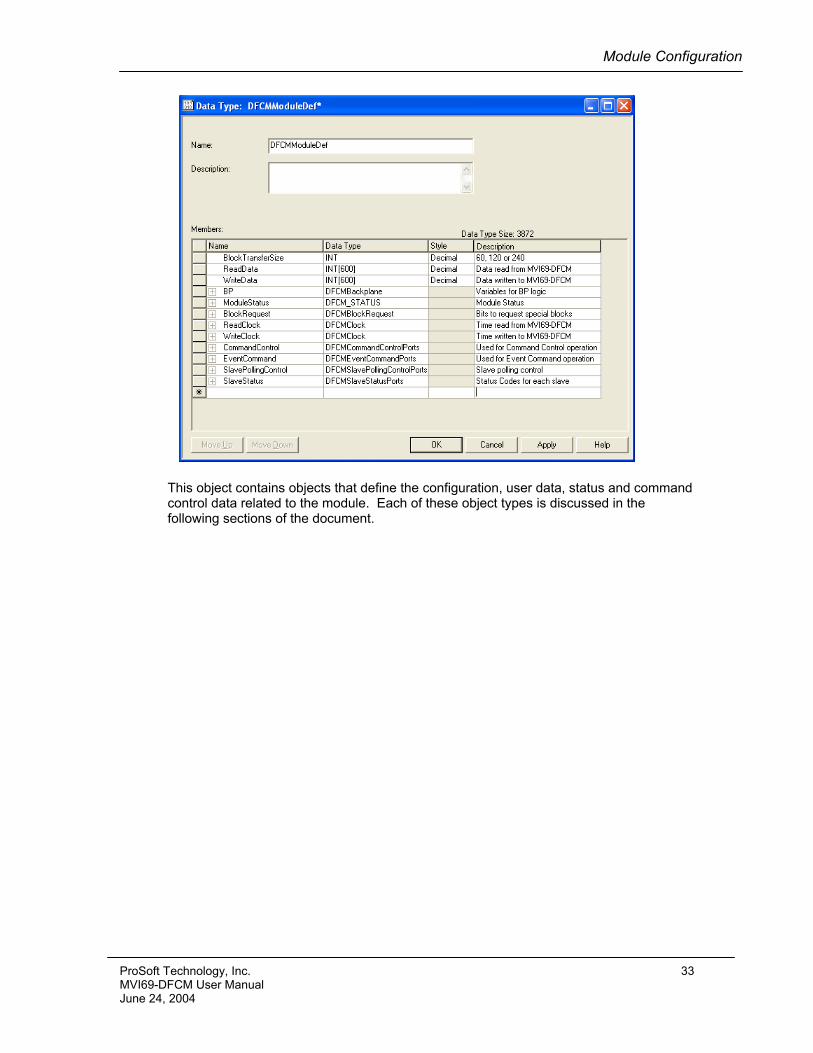
3.3.1 Module Data Object (DFCMModuleDef) All data related to the MVI69-DFCM is stored in a user defined data type. An instance of the data type is required before the module can be used. This is done by simply declaring a variable of the data type in the Controller Tags Edit Tags dialog box. The structure of the object is displayed in the figure below:
32 ProSoft Technology, Inc. MVI69-DFCM User Manual June 24, 2004
Module Configuration
This object contains objects that define the configuration, user data, status and command control data related to the module. Each of these object types is discussed in the following sections of the document.
ProSoft Technology, Inc. 33 MVI69-DFCM User Manual June 24, 2004
Module Configuration
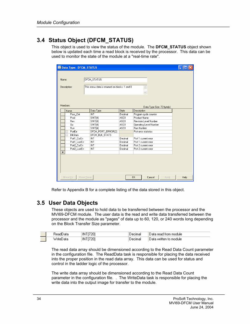
3.4 Status Object (DFCM_STATUS) This object is used to view the status of the module. The DFCM_STATUS object shown below is updated each time a read block is received by the processor. This data can be used to monitor the state of the module at a "real-time rate".
Refer to Appendix B for a complete listing of the data stored in this object.
3.5 User Data Objects These objects are used to hold data to be transferred between the processor and the MVI69-DFCM module. The user data is the read and write data transferred between the processor and the module as "pages" of data up to 60, 120, or 240 words long depending on the Block Transfer Size parameter.
The read data array should be dimensioned according to the Read Data Count parameter in the configuration file. The ReadData task is responsible for placing the data received into the proper position in the read data array. This data can be used for status and control in the ladder logic of the processor. The write data array should be dimensioned according to the Read Data Count parameter in the configuration file. . The WriteData task is responsible for placing the write data into the output image for transfer to the module.
34 ProSoft Technology, Inc. MVI69-DFCM User Manual June 24, 2004
Module Configuration
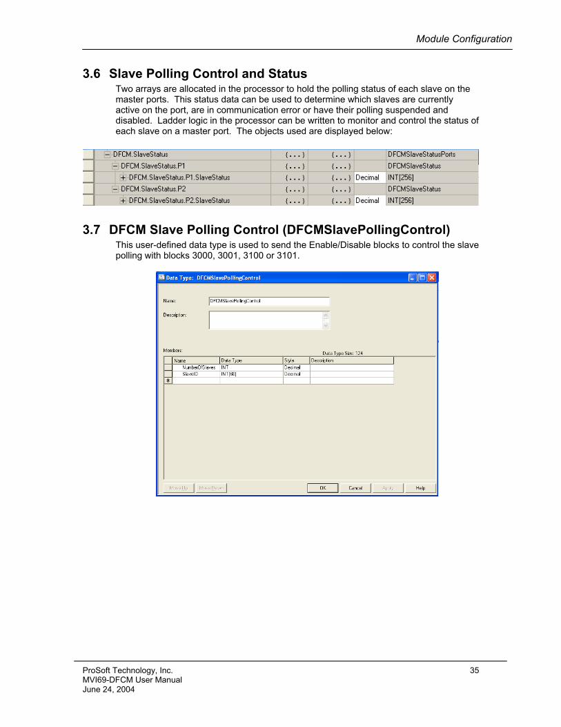
3.6 Slave Polling Control and Status Two arrays are allocated in the processor to hold the polling status of each slave on the master ports. This status data can be used to determine which slaves are currently active on the port, are in communication error or have their polling suspended and disabled. Ladder logic in the processor can be written to monitor and control the status of each slave on a master port. The objects used are displayed below:
3.7 DFCM Slave Polling Control (DFCMSlavePollingControl) This user-defined data type is used to send the Enable/Disable blocks to control the slave polling with blocks 3000, 3001, 3100 or 3101.
ProSoft Technology, Inc. 35 MVI69-DFCM User Manual June 24, 2004
Module Configuration
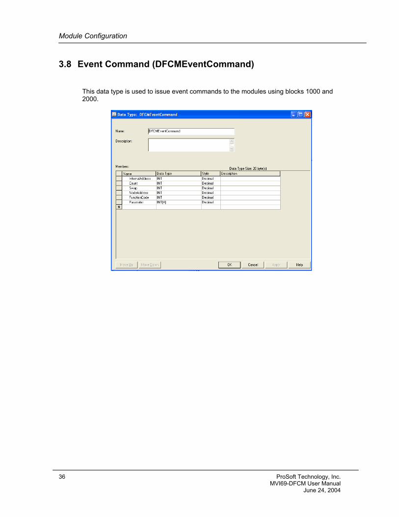
3.8 Event Command (DFCMEventCommand)
This data type is used to issue event commands to the modules using blocks 1000 and 2000.
36 ProSoft Technology, Inc. MVI69-DFCM User Manual June 24, 2004
Module Configuration
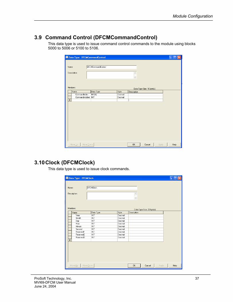
3.9 Command Control (DFCMCommandControl) This data type is used to issue command control commands to the module using blocks 5000 to 5006 or 5100 to 5106.
3.10 Clock (DFCMClock) This data type is used to issue clock commands.
ProSoft Technology, Inc. 37 MVI69-DFCM User Manual June 24, 2004

Ladder Logic
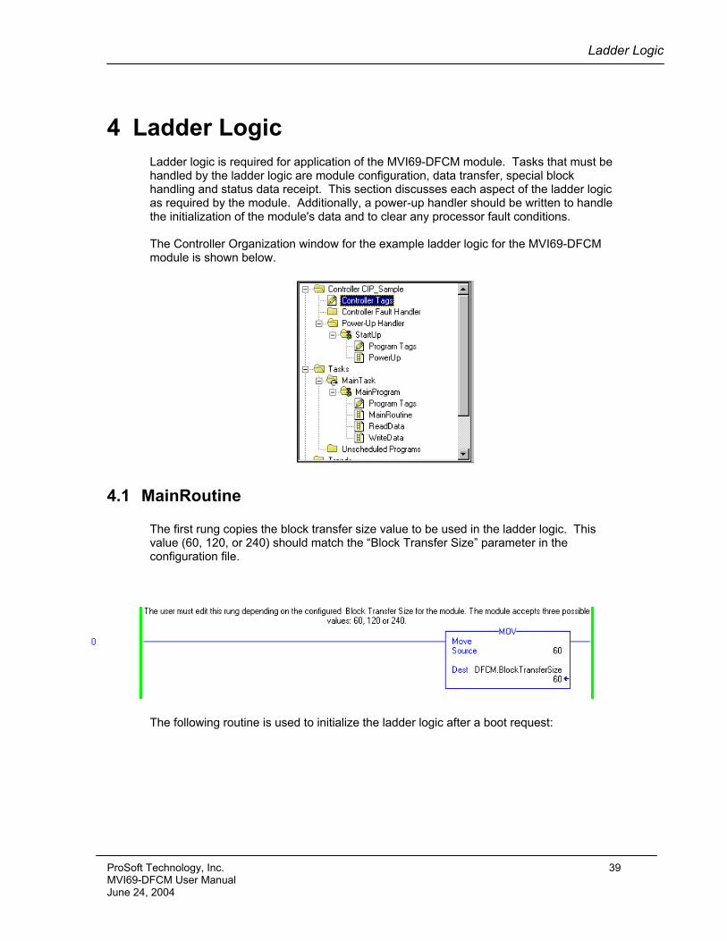
4 Ladder Logic Ladder logic is required for application of the MVI69-DFCM module. Tasks that must be handled by the ladder logic are module configuration, data transfer, special block handling and status data receipt. This section discusses each aspect of the ladder logic as required by the module. Additionally, a power-up handler should be written to handle the initialization of the module's data and to clear any processor fault conditions. The Controller Organization window for the example ladder logic for the MVI69-DFCM module is shown below.
4.1 MainRoutine The first rung copies the block transfer size value to be used in the ladder logic. This value (60, 120, or 240) should match the “Block Transfer Size” parameter in the configuration file.
The following routine is used to initialize the ladder logic after a boot request:
ProSoft Technology, Inc. 39 MVI69-DFCM User Manual June 24, 2004
Ladder Logic
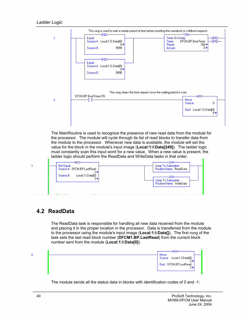
The MainRoutine is used to recognize the presence of new read data from the module for the processor. The module will cycle through its list of read blocks to transfer data from the module to the processor. Whenever new data is available, the module will set the value for the block in the module's input image (Local:1:I:Data[249]). The ladder logic must constantly scan this input word for a new value. When a new value is present, the ladder logic should perform the ReadData and WriteData tasks in that order.
4.2 ReadData
The ReadData task is responsible for handling all new data received from the module and placing it in the proper location in the processor. Data is transferred from the module to the processor using the module's input image (Local:1:I:Data[]). The first rung of the task sets the last read block number (DFCM1.BP.LastRead) from the current block number sent from the module (Local:1:I:Data[0]).
The module sends all the status data in blocks with identification codes of 0 and -1:
40 ProSoft Technology, Inc. MVI69-DFCM User Manual June 24, 2004
Ladder Logic
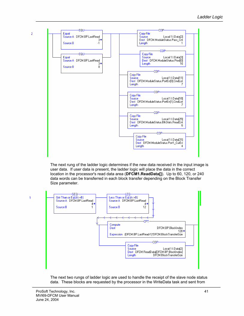
The next rung of the ladder logic determines if the new data received in the input image is user data. If user data is present, the ladder logic will place the data in the correct location in the processor's read data area (DFCM1.ReadData[]). Up to 60, 120, or 240 data words can be transferred in each block transfer depending on the Block Transfer Size parameter.
The next two rungs of ladder logic are used to handle the receipt of the slave node status data. These blocks are requested by the processor in the WriteData task and sent from
ProSoft Technology, Inc. 41 MVI69-DFCM User Manual June 24, 2004
Ladder Logic
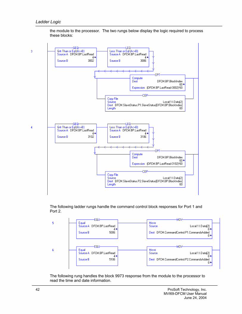
the module to the processor. The two rungs below display the logic required to process these blocks:
The following ladder rungs handle the command control block responses for Port 1 and Port 2.
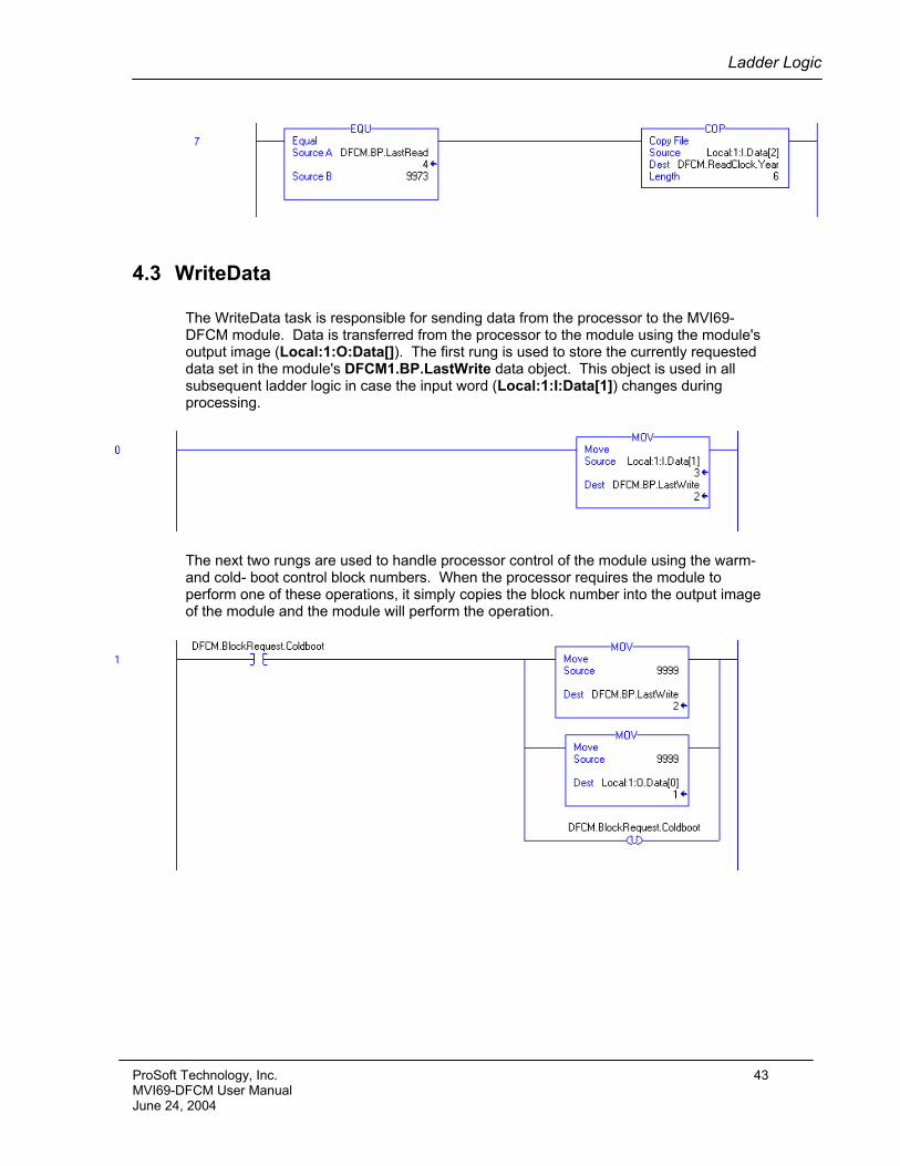
The following rung handles the block 9973 response from the module to the processor to read the time and date information.
42 ProSoft Technology, Inc. MVI69-DFCM User Manual June 24, 2004
Ladder Logic
4.3 WriteData
The WriteData task is responsible for sending data from the processor to the MVI69-DFCM module. Data is transferred from the processor to the module using the module's output image (Local:1:O:Data[]). The first rung is used to store the currently requested data set in the module's DFCM1.BP.LastWrite data object. This object is used in all subsequent ladder logic in case the input word (Local:1:I:Data[1]) changes during processing.
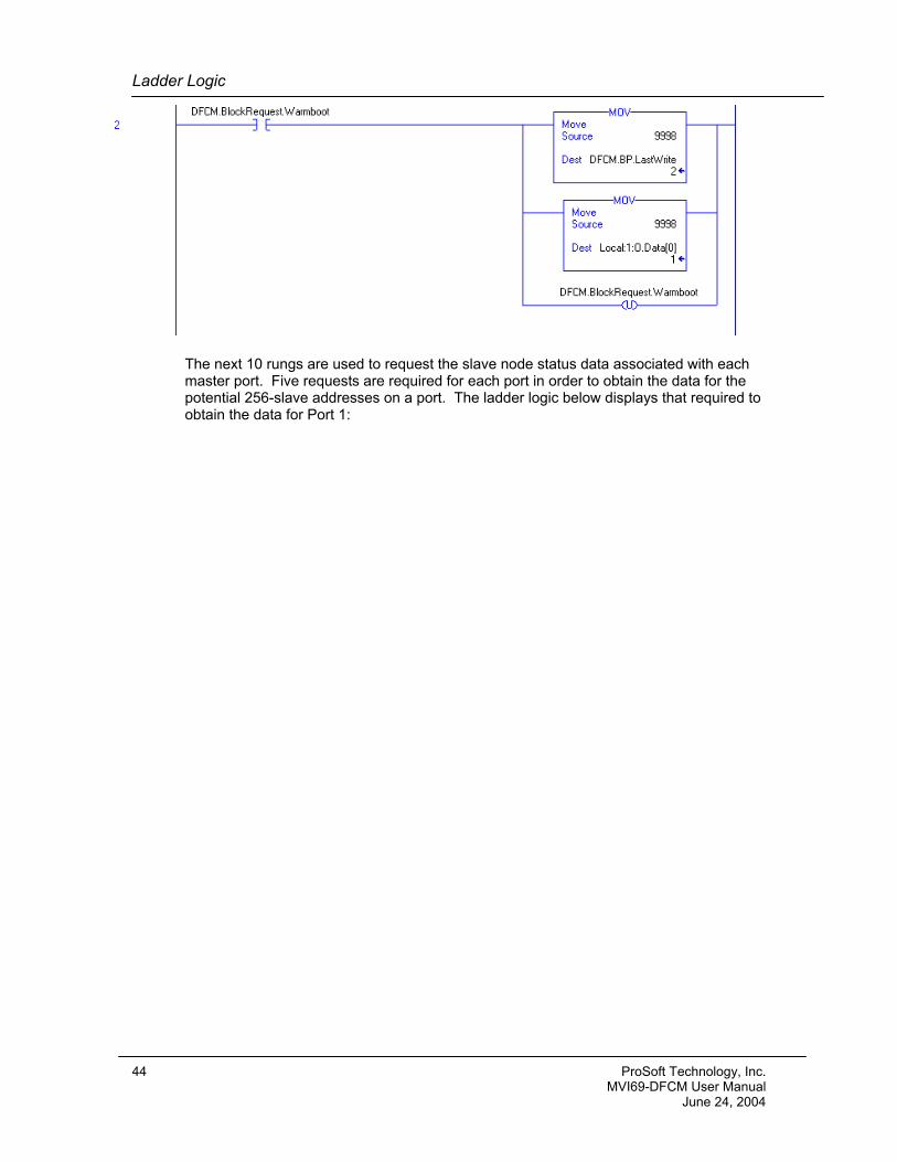
The next two rungs are used to handle processor control of the module using the warm- and cold- boot control block numbers. When the processor requires the module to perform one of these operations, it simply copies the block number into the output image of the module and the module will perform the operation.
ProSoft Technology, Inc. 43 MVI69-DFCM User Manual June 24, 2004
Ladder Logic
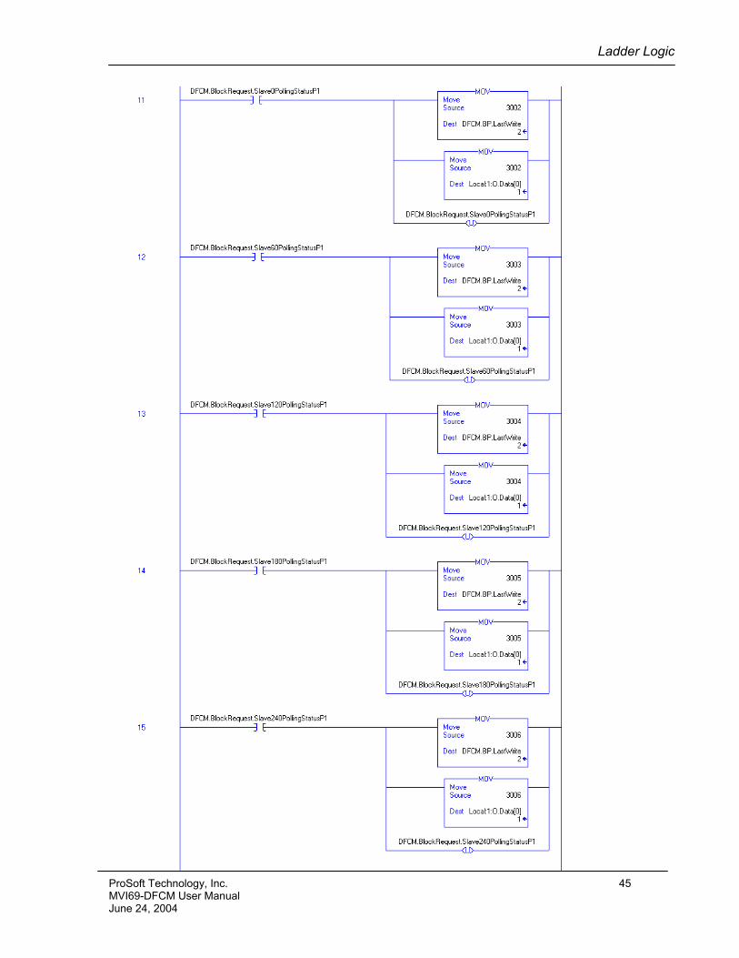
The next 10 rungs are used to request the slave node status data associated with each master port. Five requests are required for each port in order to obtain the data for the potential 256-slave addresses on a port. The ladder logic below displays that required to obtain the data for Port 1:
44 ProSoft Technology, Inc. MVI69-DFCM User Manual June 24, 2004
Ladder Logic
ProSoft Technology, Inc. 45 MVI69-DFCM User Manual June 24, 2004
Ladder Logic
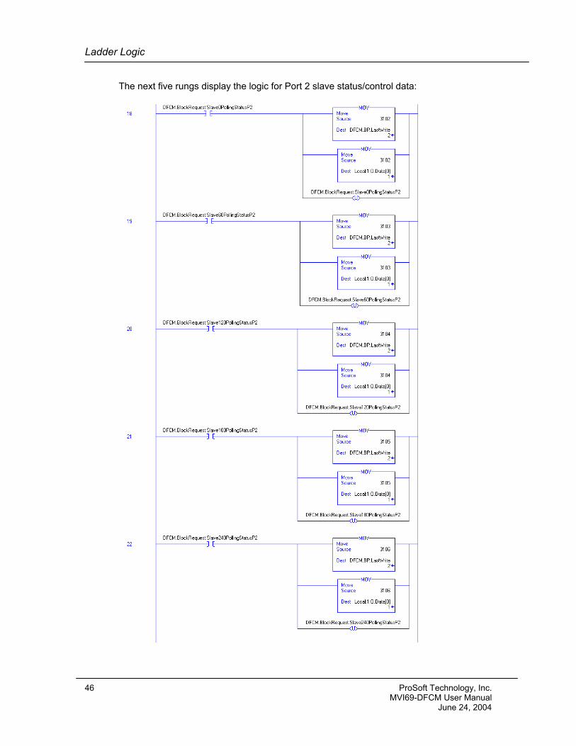
The next five rungs display the logic for Port 2 slave status/control data:
46 ProSoft Technology, Inc. MVI69-DFCM User Manual June 24, 2004
Ladder Logic
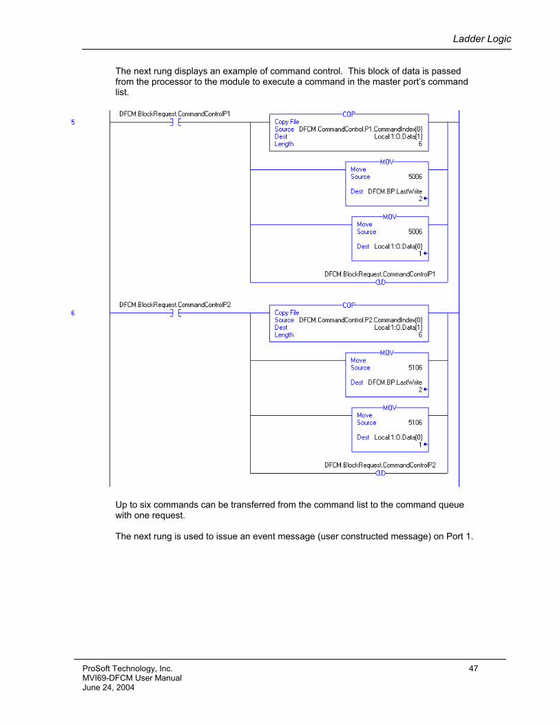
The next rung displays an example of command control. This block of data is passed from the processor to the module to execute a command in the master port’s command list.
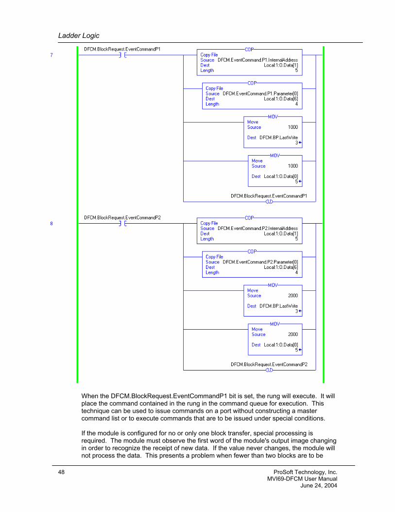
Up to six commands can be transferred from the command list to the command queue with one request. The next rung is used to issue an event message (user constructed message) on Port 1.
ProSoft Technology, Inc. 47 MVI69-DFCM User Manual June 24, 2004
Ladder Logic
When the DFCM.BlockRequest.EventCommandP1 bit is set, the rung will execute. It will place the command contained in the rung in the command queue for execution. This technique can be used to issue commands on a port without constructing a master command list or to execute commands that are to be issued under special conditions. If the module is configured for no or only one block transfer, special processing is required. The module must observe the first word of the module's output image changing in order to recognize the receipt of new data. If the value never changes, the module will not process the data. This presents a problem when fewer than two blocks are to be
48 ProSoft Technology, Inc. MVI69-DFCM User Manual June 24, 2004
Ladder Logic
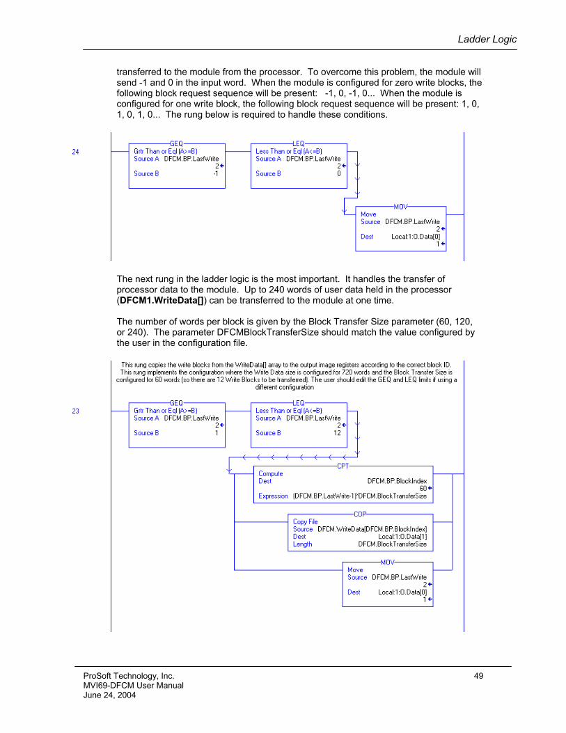
transferred to the module from the processor. To overcome this problem, the module will send -1 and 0 in the input word. When the module is configured for zero write blocks, the following block request sequence will be present: -1, 0, -1, 0... When the module is configured for one write block, the following block request sequence will be present: 1, 0, 1, 0, 1, 0... The rung below is required to handle these conditions.
The next rung in the ladder logic is the most important. It handles the transfer of processor data to the module. Up to 240 words of user data held in the processor (DFCM1.WriteData[]) can be transferred to the module at one time. The number of words per block is given by the Block Transfer Size parameter (60, 120, or 240). The parameter DFCMBlockTransferSize should match the value configured by the user in the configuration file.
ProSoft Technology, Inc. 49 MVI69-DFCM User Manual June 24, 2004

Diagnostics and Troubleshooting
5 Diagnostics and Troubleshooting The module provides diagnostic information in four forms to the user. 1) Status Data values are transferred from the module to the controller tags in the
CompactLogix processor. 2) Status data is available to other nodes on the network by reading of module's internal
database area containing status data. 3) All data contained in the module can be viewed through the configuration/debug port
to an attached terminal emulator. 4) LED status indicators on the front of the module yield information on the modules
status. The following sections explain how to obtain the Status Data from the module and the meaning of the individual LED's on the module.
5.1 Reading Status Data from the module The MVI69-DFCM module returns a 29-word Status Data block that can be used to determine the module’s operating status. This data is located in the module's database at registers 7600 to 7628 and at the location specified in the configuration. This data is transferred to the CompactLogix processor continuously with each read block.
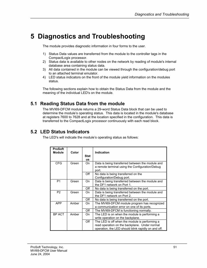
5.2 LED Status Indicators The LED's will indicate the module’s operating status as follows:
ProSoft Module
Color
Status
Indication
On
Data is being transferred between the module and a remote terminal using the Configuration/Debug port.
CFG Green
Off No data is being transferred on the Configuration/Debug port.
On Data is being transferred between the module and the DF1 network on Port 1.
P1
Green
Off No data is being transferred on the port. On Data is being transferred between the module and
the DF1 network on Port 2. P2
Green
Off No data is being transferred on the port. On The MVI69-DFCM module program has recognized
a communication error on one of its ports. APP Amber
Off The MVI69-DFCM is functioning normally. On The LED is on when the module is performing a
write operation on the backplane. BP ACT Amber
Off The LED is off when the module is performing a read operation on the backplane. Under normal operation, the LED should blink rapidly on and off.
ProSoft Technology, Inc. 51 MVI69-DFCM User Manual June 24, 2004
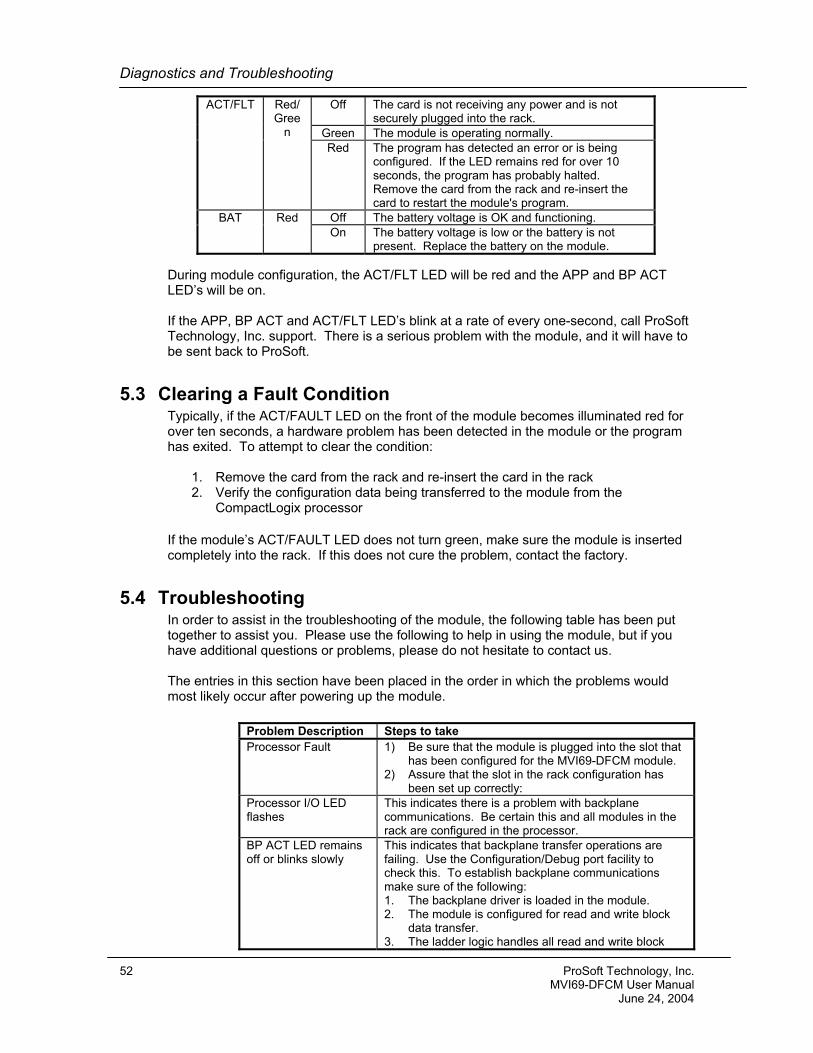
Diagnostics and Troubleshooting
Off The card is not receiving any power and is not securely plugged into the rack.
Green The module is operating normally.
ACT/FLT Red/ Gree
n Red The program has detected an error or is being
configured. If the LED remains red for over 10 seconds, the program has probably halted. Remove the card from the rack and re-insert the card to restart the module's program.
Off The battery voltage is OK and functioning. BAT Red On The battery voltage is low or the battery is not
present. Replace the battery on the module.
During module configuration, the ACT/FLT LED will be red and the APP and BP ACT LED’s will be on. If the APP, BP ACT and ACT/FLT LED’s blink at a rate of every one-second, call ProSoft Technology, Inc. support. There is a serious problem with the module, and it will have to be sent back to ProSoft.
5.3 Clearing a Fault Condition Typically, if the ACT/FAULT LED on the front of the module becomes illuminated red for over ten seconds, a hardware problem has been detected in the module or the program has exited. To attempt to clear the condition:
1. Remove the card from the rack and re-insert the card in the rack 2. Verify the configuration data being transferred to the module from the
CompactLogix processor
If the module’s ACT/FAULT LED does not turn green, make sure the module is inserted completely into the rack. If this does not cure the problem, contact the factory.
5.4 Troubleshooting In order to assist in the troubleshooting of the module, the following table has been put together to assist you. Please use the following to help in using the module, but if you have additional questions or problems, please do not hesitate to contact us. The entries in this section have been placed in the order in which the problems would most likely occur after powering up the module.
Problem Description Steps to take Processor Fault
1) Be sure that the module is plugged into the slot that has been configured for the MVI69-DFCM module.
2) Assure that the slot in the rack configuration has been set up correctly:
Processor I/O LED flashes
This indicates there is a problem with backplane communications. Be certain this and all modules in the rack are configured in the processor.
BP ACT LED remains off or blinks slowly
This indicates that backplane transfer operations are failing. Use the Configuration/Debug port facility to check this. To establish backplane communications make sure of the following: 1. The backplane driver is loaded in the module. 2. The module is configured for read and write block
data transfer. 3. The ladder logic handles all read and write block
52 ProSoft Technology, Inc. MVI69-DFCM User Manual June 24, 2004
Diagnostics and Troubleshooting
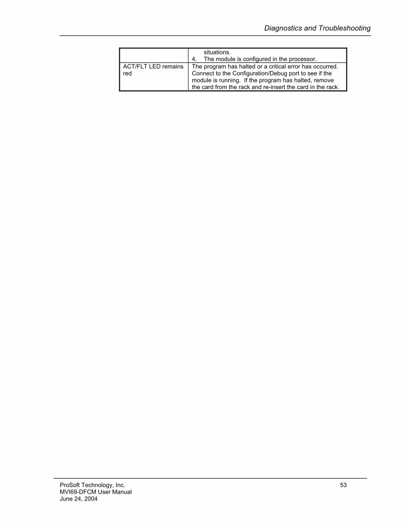
situations. 4. The module is configured in the processor.
ACT/FLT LED remains red
The program has halted or a critical error has occurred. Connect to the Configuration/Debug port to see if the module is running. If the program has halted, remove the card from the rack and re-insert the card in the rack.
ProSoft Technology, Inc. 53 MVI69-DFCM User Manual June 24, 2004
Diagnostics and Troubleshooting
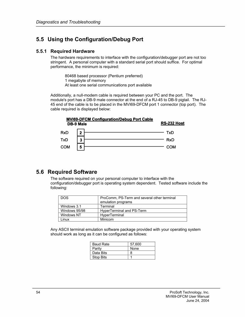
5.5 Using the Configuration/Debug Port
5.5.1 Required Hardware The hardware requirements to interface with the configuration/debugger port are not too stringent. A personal computer with a standard serial port should suffice. For optimal performance, the minimum is required: 80468 based processor (Pentium preferred) 1 megabyte of memory At least one serial communications port available
Additionally, a null-modem cable is required between your PC and the port. The module's port has a DB-9 male connector at the end of a RJ-45 to DB-9 pigtail. The RJ-45 end of the cable is to be placed in the MVI69-DFCM port 1 connector (top port). The cable required is displayed below:
2
3
5
RxD
TxD
COM
MVI69-DFCM Configuration/Debug Port CableDB-9 Male
RxD
TxD
COM
RS-232 Host
2
3
5
RxD
TxD
COM
MVI69-DFCM Configuration/Debug Port CableDB-9 Male
RxD
TxD
COM
RS-232 Host
5.6 Required Software The software required on your personal computer to interface with the configuration/debugger port is operating system dependent. Tested software include the following:
DOS ProComm, PS-Term and several other terminal
emulation programs Windows 3.1 Terminal Windows 95/98 HyperTerminal and PS-Term Windows NT HyperTerminal Linux Minicom
Any ASCII terminal emulation software package provided with your operating system should work as long as it can be configured as follows:
Baud Rate 57,600 Parity None Data Bits 8 Stop Bits 1
54 ProSoft Technology, Inc. MVI69-DFCM User Manual June 24, 2004
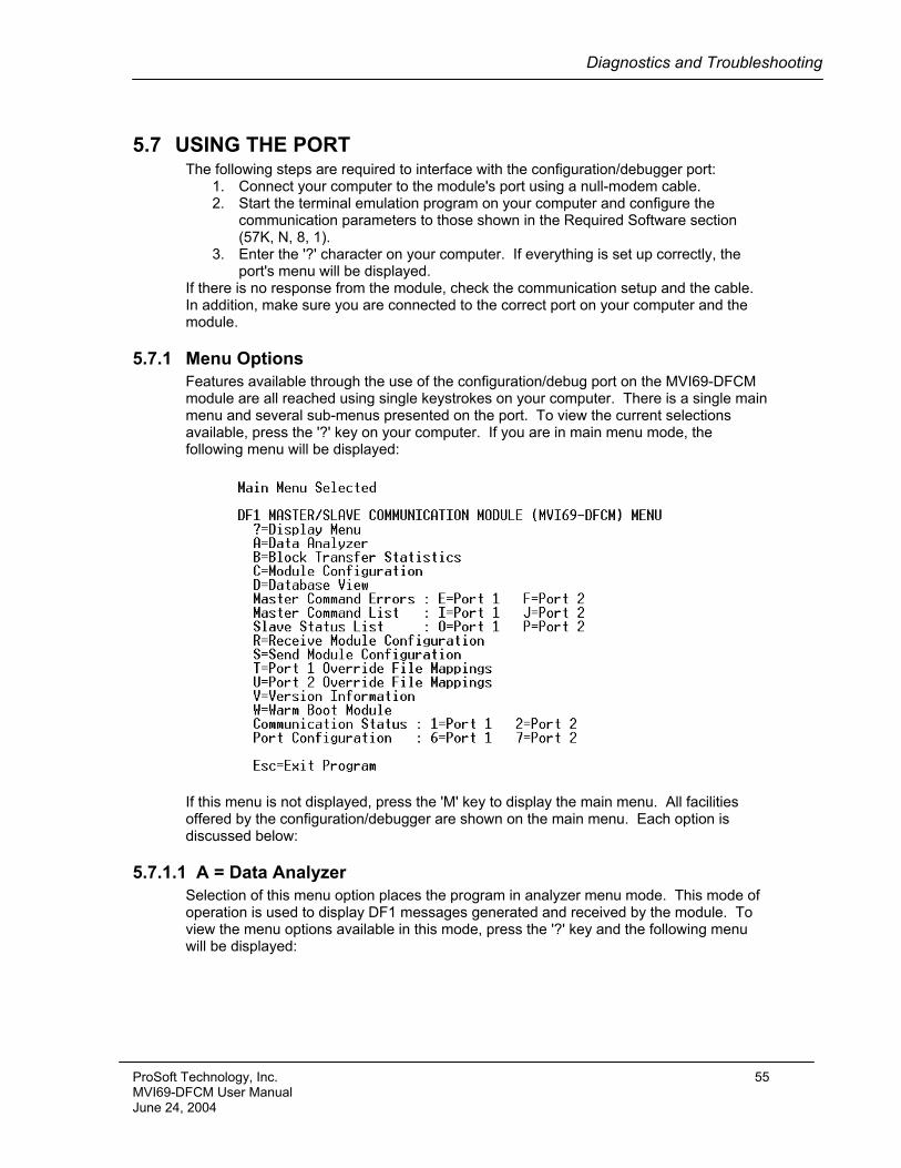
Diagnostics and Troubleshooting
5.7 USING THE PORT The following steps are required to interface with the configuration/debugger port:
1. Connect your computer to the module's port using a null-modem cable. 2. Start the terminal emulation program on your computer and configure the
communication parameters to those shown in the Required Software section (57K, N, 8, 1).
3. Enter the '?' character on your computer. If everything is set up correctly, the port's menu will be displayed.
If there is no response from the module, check the communication setup and the cable. In addition, make sure you are connected to the correct port on your computer and the module.
5.7.1 Menu Options Features available through the use of the configuration/debug port on the MVI69-DFCM module are all reached using single keystrokes on your computer. There is a single main menu and several sub-menus presented on the port. To view the current selections available, press the '?' key on your computer. If you are in main menu mode, the following menu will be displayed:
If this menu is not displayed, press the 'M' key to display the main menu. All facilities offered by the configuration/debugger are shown on the main menu. Each option is discussed below:
5.7.1.1 A = Data Analyzer Selection of this menu option places the program in analyzer menu mode. This mode of operation is used to display DF1 messages generated and received by the module. To view the menu options available in this mode, press the '?' key and the following menu will be displayed:
ProSoft Technology, Inc. 55 MVI69-DFCM User Manual June 24, 2004
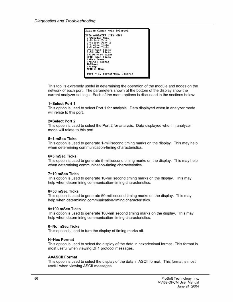
Diagnostics and Troubleshooting
This tool is extremely useful in determining the operation of the module and nodes on the network of each port. The parameters shown at the bottom of the display show the current analyzer settings. Each of the menu options is discussed in the sections below: 1=Select Port 1 This option is used to select Port 1 for analysis. Data displayed when in analyzer mode will relate to this port. 2=Select Port 2 This option is used to select the Port 2 for analysis. Data displayed when in analyzer mode will relate to this port. 5=1 mSec Ticks This option is used to generate 1-millisecond timing marks on the display. This may help when determining communication-timing characteristics. 6=5 mSec Ticks This option is used to generate 5-millisecond timing marks on the display. This may help when determining communication-timing characteristics. 7=10 mSec Ticks This option is used to generate 10-millisecond timing marks on the display. This may help when determining communication-timing characteristics. 8=50 mSec Ticks This option is used to generate 50-millisecond timing marks on the display. This may help when determining communication-timing characteristics. 9=100 mSec Ticks This option is used to generate 100-millisecond timing marks on the display. This may help when determining communication-timing characteristics. 0=No mSec Ticks This option is used to turn the display of timing marks off. H=Hex Format This option is used to select the display of the data in hexadecimal format. This format is most useful when viewing DF1 protocol messages. A=ASCII Format This option is used to select the display of the data in ASCII format. This format is most useful when viewing ASCII messages.
56 ProSoft Technology, Inc. MVI69-DFCM User Manual June 24, 2004
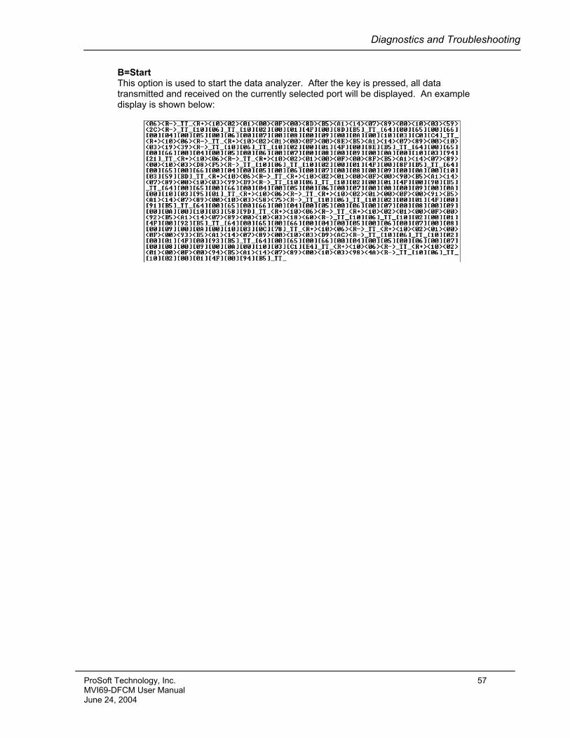
Diagnostics and Troubleshooting
B=Start This option is used to start the data analyzer. After the key is pressed, all data transmitted and received on the currently selected port will be displayed. An example display is shown below:
ProSoft Technology, Inc. 57 MVI69-DFCM User Manual June 24, 2004
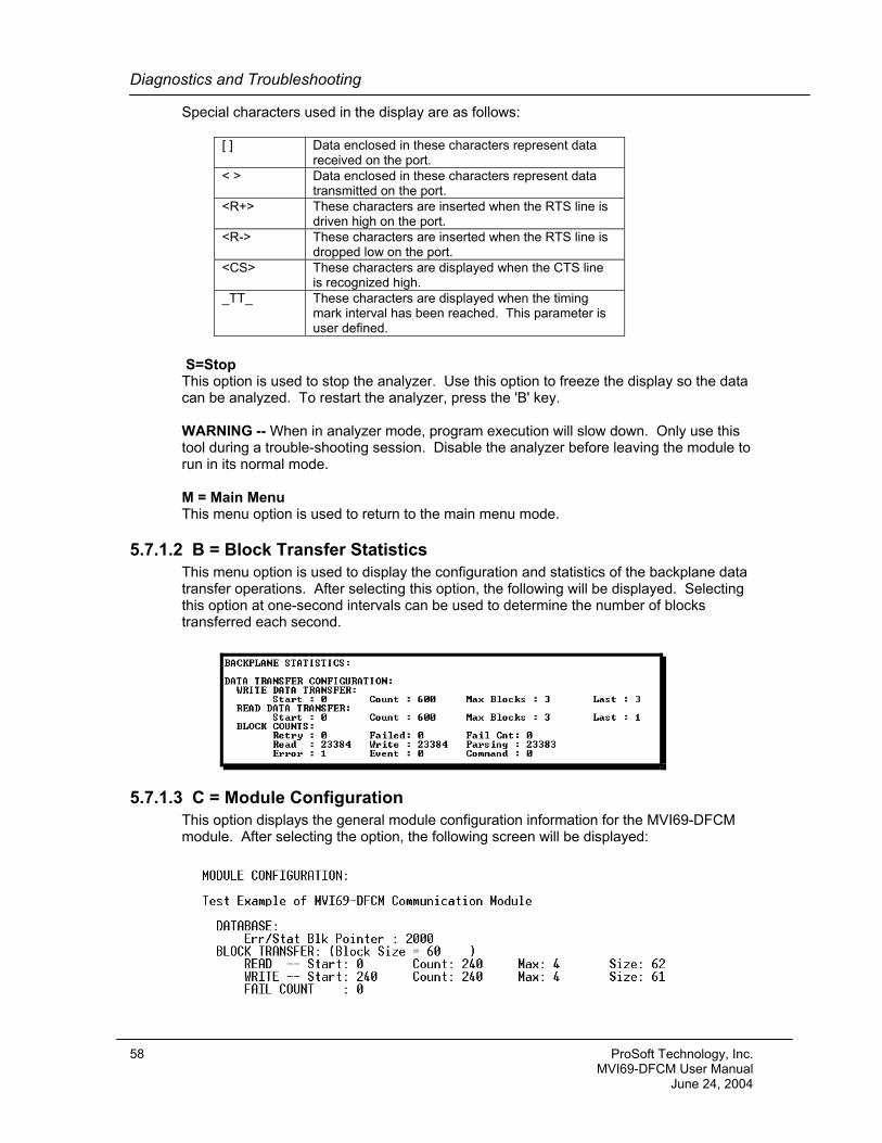
Diagnostics and Troubleshooting
Special characters used in the display are as follows:
[ ] Data enclosed in these characters represent data received on the port.
< > Data enclosed in these characters represent data transmitted on the port.
<R+> These characters are inserted when the RTS line is driven high on the port.
<R-> These characters are inserted when the RTS line is dropped low on the port.
<CS> These characters are displayed when the CTS line is recognized high.
_TT_ These characters are displayed when the timing mark interval has been reached. This parameter is user defined.
S=Stop This option is used to stop the analyzer. Use this option to freeze the display so the data can be analyzed. To restart the analyzer, press the 'B' key. WARNING -- When in analyzer mode, program execution will slow down. Only use this tool during a trouble-shooting session. Disable the analyzer before leaving the module to run in its normal mode. M = Main Menu This menu option is used to return to the main menu mode.
5.7.1.2 B = Block Transfer Statistics This menu option is used to display the configuration and statistics of the backplane data transfer operations. After selecting this option, the following will be displayed. Selecting this option at one-second intervals can be used to determine the number of blocks transferred each second.
5.7.1.3 C = Module Configuration This option displays the general module configuration information for the MVI69-DFCM module. After selecting the option, the following screen will be displayed:
58 ProSoft Technology, Inc. MVI69-DFCM User Manual June 24, 2004
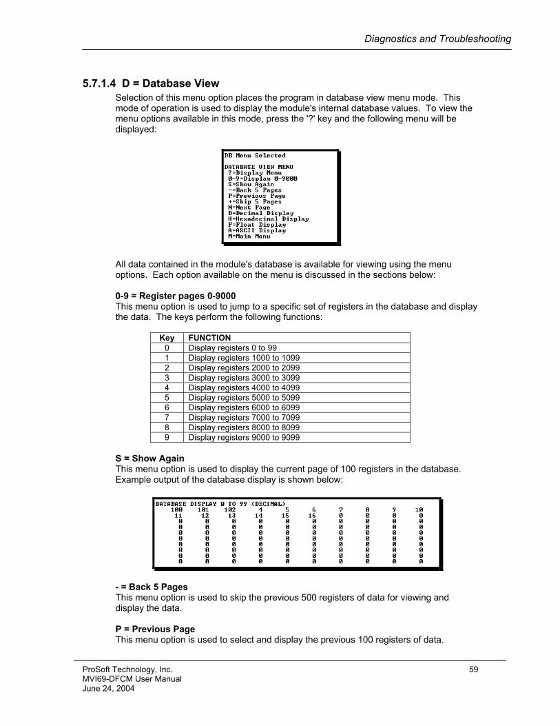
Diagnostics and Troubleshooting
5.7.1.4 D = Database View Selection of this menu option places the program in database view menu mode. This mode of operation is used to display the module's internal database values. To view the menu options available in this mode, press the '?' key and the following menu will be displayed:
All data contained in the module's database is available for viewing using the menu options. Each option available on the menu is discussed in the sections below: 0-9 = Register pages 0-9000 This menu option is used to jump to a specific set of registers in the database and display the data. The keys perform the following functions:
Key FUNCTION 0 Display registers 0 to 99 1 Display registers 1000 to 1099 2 Display registers 2000 to 2099 3 Display registers 3000 to 3099 4 Display registers 4000 to 4099 5 Display registers 5000 to 5099 6 Display registers 6000 to 6099 7 Display registers 7000 to 7099 8 Display registers 8000 to 8099 9 Display registers 9000 to 9099
S = Show Again This menu option is used to display the current page of 100 registers in the database. Example output of the database display is shown below:
- = Back 5 Pages This menu option is used to skip the previous 500 registers of data for viewing and display the data. P = Previous Page This menu option is used to select and display the previous 100 registers of data.
ProSoft Technology, Inc. 59 MVI69-DFCM User Manual June 24, 2004
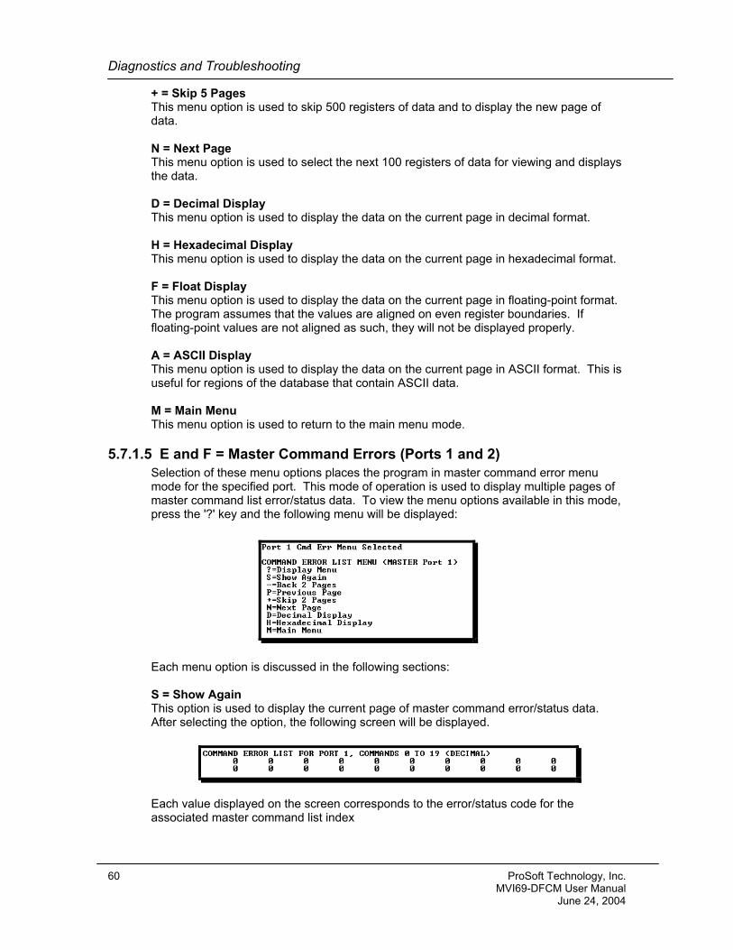
Diagnostics and Troubleshooting
+ = Skip 5 Pages This menu option is used to skip 500 registers of data and to display the new page of data. N = Next Page This menu option is used to select the next 100 registers of data for viewing and displays the data. D = Decimal Display This menu option is used to display the data on the current page in decimal format. H = Hexadecimal Display This menu option is used to display the data on the current page in hexadecimal format. F = Float Display This menu option is used to display the data on the current page in floating-point format. The program assumes that the values are aligned on even register boundaries. If floating-point values are not aligned as such, they will not be displayed properly. A = ASCII Display This menu option is used to display the data on the current page in ASCII format. This is useful for regions of the database that contain ASCII data. M = Main Menu This menu option is used to return to the main menu mode.
5.7.1.5 E and F = Master Command Errors (Ports 1 and 2) Selection of these menu options places the program in master command error menu mode for the specified port. This mode of operation is used to display multiple pages of master command list error/status data. To view the menu options available in this mode, press the '?' key and the following menu will be displayed:
Each menu option is discussed in the following sections: S = Show Again This option is used to display the current page of master command error/status data. After selecting the option, the following screen will be displayed.
Each value displayed on the screen corresponds to the error/status code for the associated master command list index
60 ProSoft Technology, Inc. MVI69-DFCM User Manual June 24, 2004
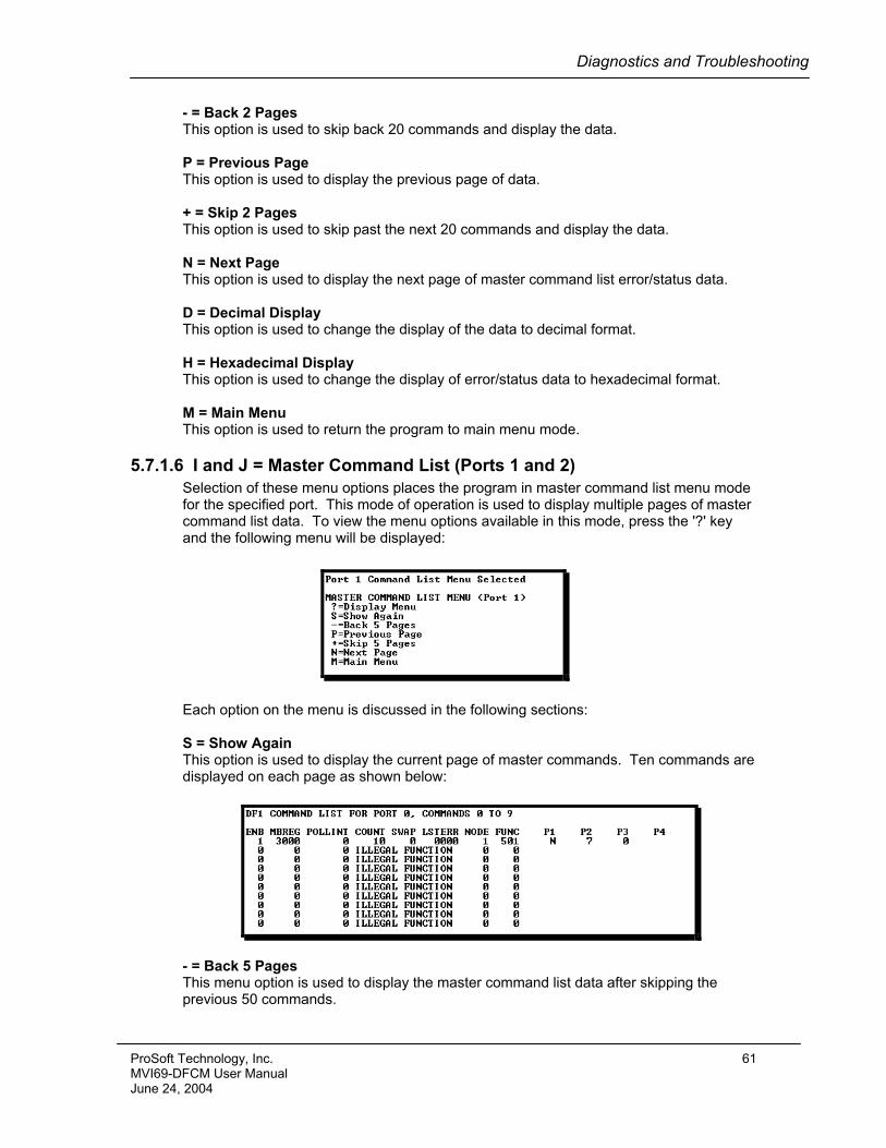
Diagnostics and Troubleshooting
- = Back 2 Pages This option is used to skip back 20 commands and display the data. P = Previous Page This option is used to display the previous page of data. + = Skip 2 Pages This option is used to skip past the next 20 commands and display the data. N = Next Page This option is used to display the next page of master command list error/status data. D = Decimal Display This option is used to change the display of the data to decimal format. H = Hexadecimal Display This option is used to change the display of error/status data to hexadecimal format. M = Main Menu This option is used to return the program to main menu mode.
5.7.1.6 I and J = Master Command List (Ports 1 and 2) Selection of these menu options places the program in master command list menu mode for the specified port. This mode of operation is used to display multiple pages of master command list data. To view the menu options available in this mode, press the '?' key and the following menu will be displayed:
Each option on the menu is discussed in the following sections: S = Show Again This option is used to display the current page of master commands. Ten commands are displayed on each page as shown below:
- = Back 5 Pages This menu option is used to display the master command list data after skipping the previous 50 commands.
ProSoft Technology, Inc. 61 MVI69-DFCM User Manual June 24, 2004
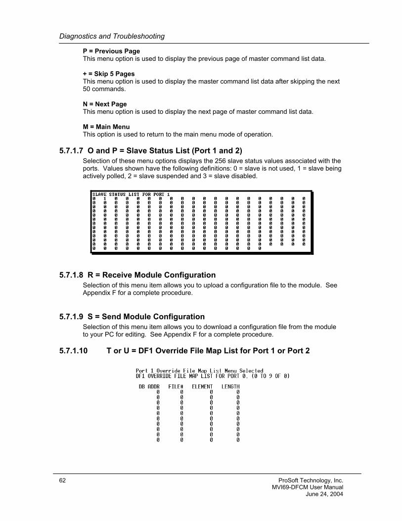
Diagnostics and Troubleshooting
P = Previous Page This menu option is used to display the previous page of master command list data. + = Skip 5 Pages This menu option is used to display the master command list data after skipping the next 50 commands. N = Next Page This menu option is used to display the next page of master command list data. M = Main Menu This option is used to return to the main menu mode of operation.
5.7.1.7 O and P = Slave Status List (Port 1 and 2) Selection of these menu options displays the 256 slave status values associated with the ports. Values shown have the following definitions: 0 = slave is not used, 1 = slave being actively polled, 2 = slave suspended and 3 = slave disabled.
5.7.1.8 R = Receive Module Configuration Selection of this menu item allows you to upload a configuration file to the module. See Appendix F for a complete procedure.
5.7.1.9 S = Send Module Configuration Selection of this menu item allows you to download a configuration file from the module to your PC for editing. See Appendix F for a complete procedure.
5.7.1.10 T or U = DF1 Override File Map List for Port 1 or Port 2
62 ProSoft Technology, Inc. MVI69-DFCM User Manual June 24, 2004
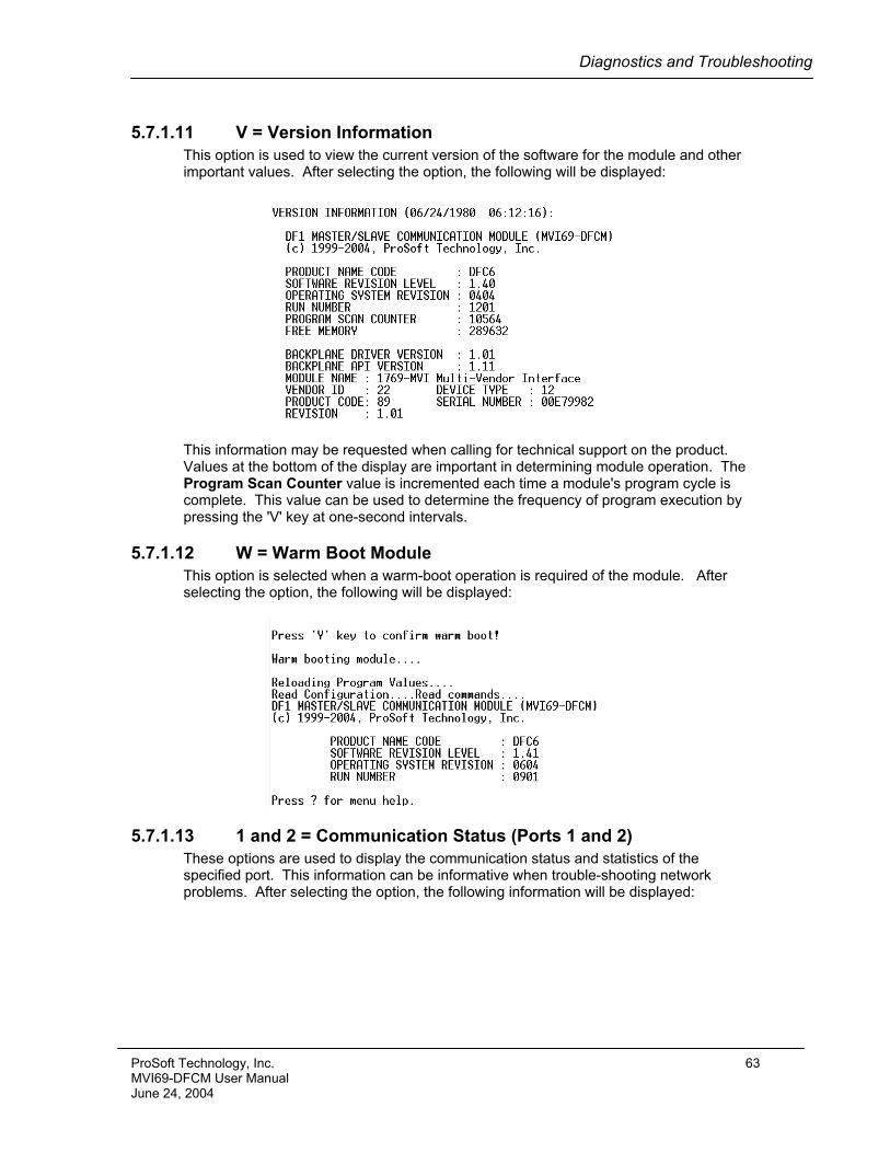
Diagnostics and Troubleshooting
5.7.1.11 V = Version Information This option is used to view the current version of the software for the module and other important values. After selecting the option, the following will be displayed:
This information may be requested when calling for technical support on the product. Values at the bottom of the display are important in determining module operation. The Program Scan Counter value is incremented each time a module's program cycle is complete. This value can be used to determine the frequency of program execution by pressing the 'V' key at one-second intervals.
5.7.1.12 W = Warm Boot Module This option is selected when a warm-boot operation is required of the module. After selecting the option, the following will be displayed:
5.7.1.13 1 and 2 = Communication Status (Ports 1 and 2) These options are used to display the communication status and statistics of the specified port. This information can be informative when trouble-shooting network problems. After selecting the option, the following information will be displayed:
ProSoft Technology, Inc. 63 MVI69-DFCM User Manual June 24, 2004
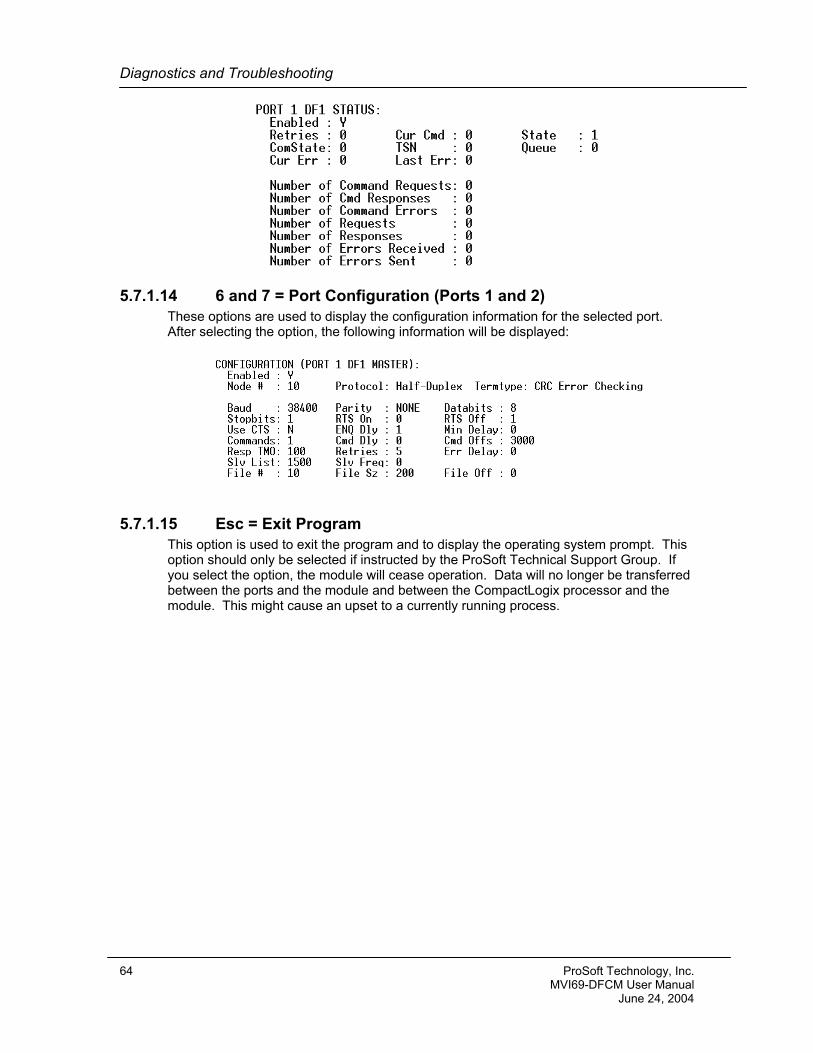
Diagnostics and Troubleshooting
5.7.1.14 6 and 7 = Port Configuration (Ports 1 and 2) These options are used to display the configuration information for the selected port. After selecting the option, the following information will be displayed:
5.7.1.15 Esc = Exit Program This option is used to exit the program and to display the operating system prompt. This option should only be selected if instructed by the ProSoft Technical Support Group. If you select the option, the module will cease operation. Data will no longer be transferred between the ports and the module and between the CompactLogix processor and the module. This might cause an upset to a currently running process.
64 ProSoft Technology, Inc. MVI69-DFCM User Manual June 24, 2004
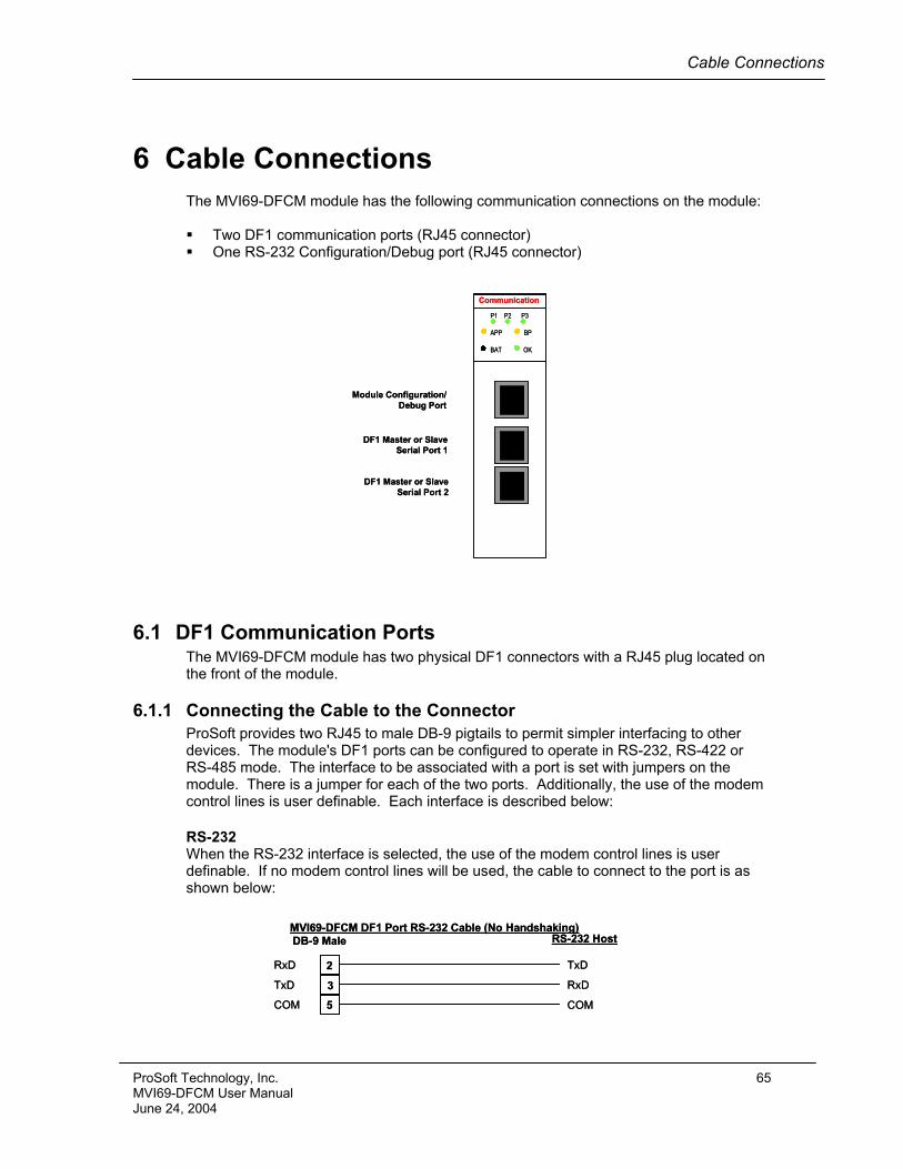
Cable Connections
6 Cable Connections The MVI69-DFCM module has the following communication connections on the module: Two DF1 communication ports (RJ45 connector) One RS-232 Configuration/Debug port (RJ45 connector)
P1 P2 P3
APP BP
BAT OK
Module Configuration/Debug Port
DF1 Master or SlaveSerial Port 1
DF1 Master or SlaveSerial Port 2
P1 P2 P3
APP BP
BAT OK
Module Configuration/Debug Port
DF1 Master or SlaveSerial Port 1
DF1 Master or SlaveSerial Port 2
CommunicationCommunication
6.1 DF1 Communication Ports The MVI69-DFCM module has two physical DF1 connectors with a RJ45 plug located on the front of the module.
6.1.1 Connecting the Cable to the Connector ProSoft provides two RJ45 to male DB-9 pigtails to permit simpler interfacing to other devices. The module's DF1 ports can be configured to operate in RS-232, RS-422 or RS-485 mode. The interface to be associated with a port is set with jumpers on the module. There is a jumper for each of the two ports. Additionally, the use of the modem control lines is user definable. Each interface is described below:
RS-232 When the RS-232 interface is selected, the use of the modem control lines is user definable. If no modem control lines will be used, the cable to connect to the port is as shown below:
2
3
5
RxD
TxD
COM
MVI69-DFCM DF1 Port RS-232 Cable (No Handshaking)DB-9 Male
RxD
TxD
COM
RS-232 Host
2
3
5
RxD
TxD
COM
MVI69-DFCM DF1 Port RS-232 Cable (No Handshaking)DB-9 Male
RxD
TxD
COM
RS-232 Host
ProSoft Technology, Inc. 65 MVI69-DFCM User Manual June 24, 2004
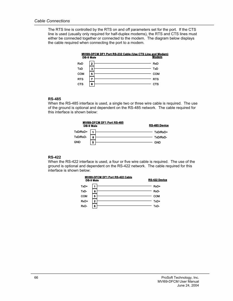
Cable Connections
The RTS line is controlled by the RTS on and off parameters set for the port. If the CTS line is used (usually only required for half-duplex modems), the RTS and CTS lines must either be connected together or connected to the modem. The diagram below displays the cable required when connecting the port to a modem.
2
3
5
RxD
TxD
COM
MVI69-DFCM DF1 Port RS-232 Cable (Use CTS Line and Modem)DB-9 Male
TxD
RxD
COM
Modem
7RTS RTS
8CTS CTS
2
3
5
RxD
TxD
COM
MVI69-DFCM DF1 Port RS-232 Cable (Use CTS Line and Modem)DB-9 Male
TxD
RxD
COM
Modem
7RTS RTS
8CTS CTS
RS-485 When the RS-485 interface is used, a single two or three wire cable is required. The use of the ground is optional and dependent on the RS-485 network. The cable required for this interface is shown below:
1
8
5
TxD/RxD+
TxD/RxD-
GND
MVI69-DFCM DF1 Port RS-485DB-9 Male
TxD/RxD-
TxD/RxD+
GND
RS-485 Device
1
8
5
TxD/RxD+
TxD/RxD-
GND
MVI69-DFCM DF1 Port RS-485DB-9 Male
TxD/RxD-
TxD/RxD+
GND
RS-485 Device
RS-422 When the RS-422 interface is used, a four or five wire cable is required. The use of the ground is optional and dependent on the RS-422 network. The cable required for this interface is shown below:
1
8
5
TxD+
TxD-
COM
MVI69-DFCM DF1 Port RS-422 CableDB-9 Male
RxD-
RxD+
COM
RS-422 Device
2RxD+ TxD+
6RxD- TxD-
1
8
5
TxD+
TxD-
COM
MVI69-DFCM DF1 Port RS-422 CableDB-9 Male
RxD-
RxD+
COM
RS-422 Device
2RxD+ TxD+
6RxD- TxD-
66 ProSoft Technology, Inc. MVI69-DFCM User Manual June 24, 2004
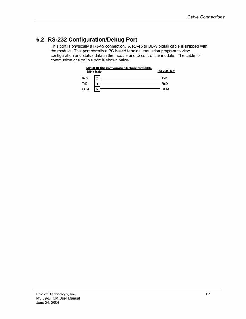
Cable Connections
6.2 RS-232 Configuration/Debug Port This port is physically a RJ-45 connection. A RJ-45 to DB-9 pigtail cable is shipped with the module. This port permits a PC based terminal emulation program to view configuration and status data in the module and to control the module. The cable for communications on this port is shown below:
2
3
5
RxD
TxD
COM
MVI69-DFCM Configuration/Debug Port CableDB-9 Male
RxD
TxD
COM
RS-232 Host
2
3
5
RxD
TxD
COM
MVI69-DFCM Configuration/Debug Port CableDB-9 Male
RxD
TxD
COM
RS-232 Host
ProSoft Technology, Inc. 67 MVI69-DFCM User Manual June 24, 2004

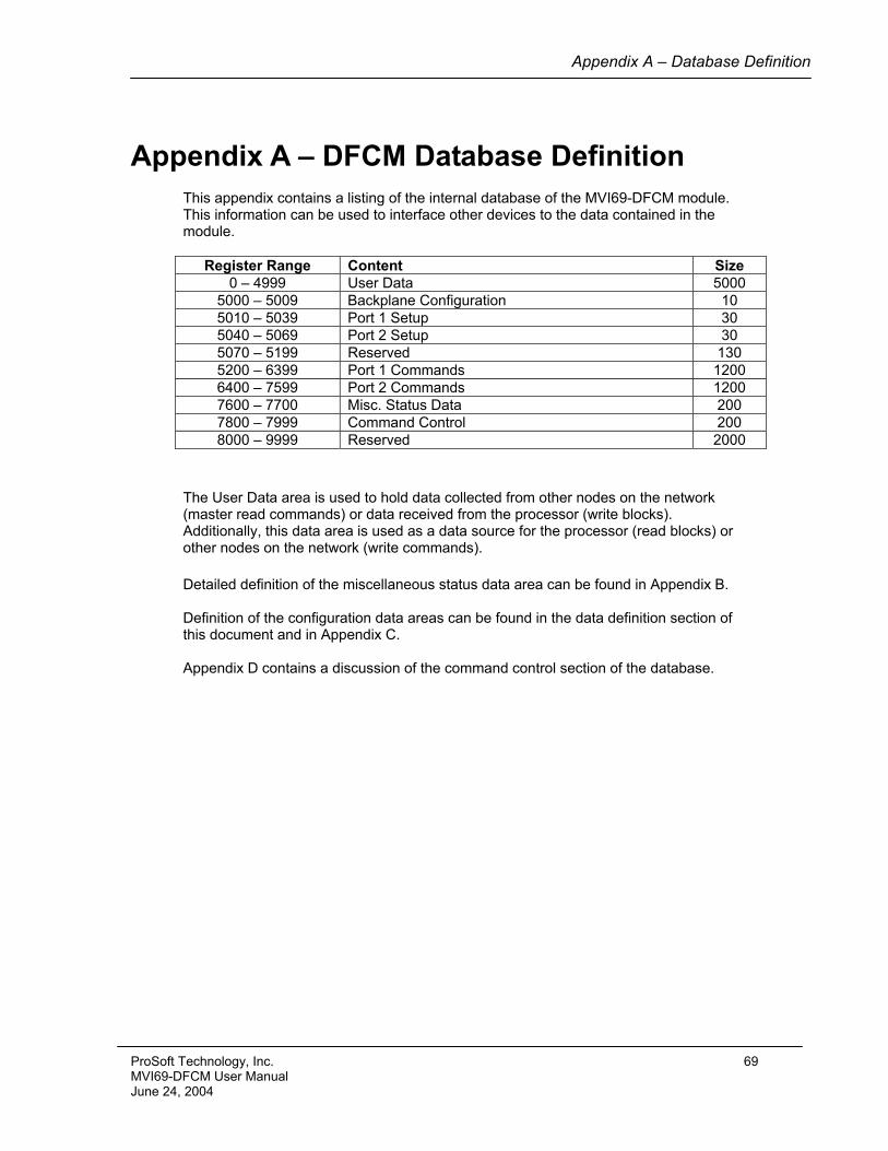
Appendix A – Database Definition
Appendix A – DFCM Database Definition This appendix contains a listing of the internal database of the MVI69-DFCM module. This information can be used to interface other devices to the data contained in the module.
Register Range Content Size 0 – 4999 User Data 5000
5000 – 5009 Backplane Configuration 10 5010 – 5039 Port 1 Setup 30 5040 – 5069 Port 2 Setup 30 5070 – 5199 Reserved 130 5200 – 6399 Port 1 Commands 1200 6400 – 7599 Port 2 Commands 1200 7600 – 7700 Misc. Status Data 200 7800 – 7999 Command Control 200 8000 – 9999 Reserved 2000
The User Data area is used to hold data collected from other nodes on the network (master read commands) or data received from the processor (write blocks). Additionally, this data area is used as a data source for the processor (read blocks) or other nodes on the network (write commands).
Detailed definition of the miscellaneous status data area can be found in Appendix B. Definition of the configuration data areas can be found in the data definition section of this document and in Appendix C. Appendix D contains a discussion of the command control section of the database.
ProSoft Technology, Inc. 69 MVI69-DFCM User Manual June 24, 2004

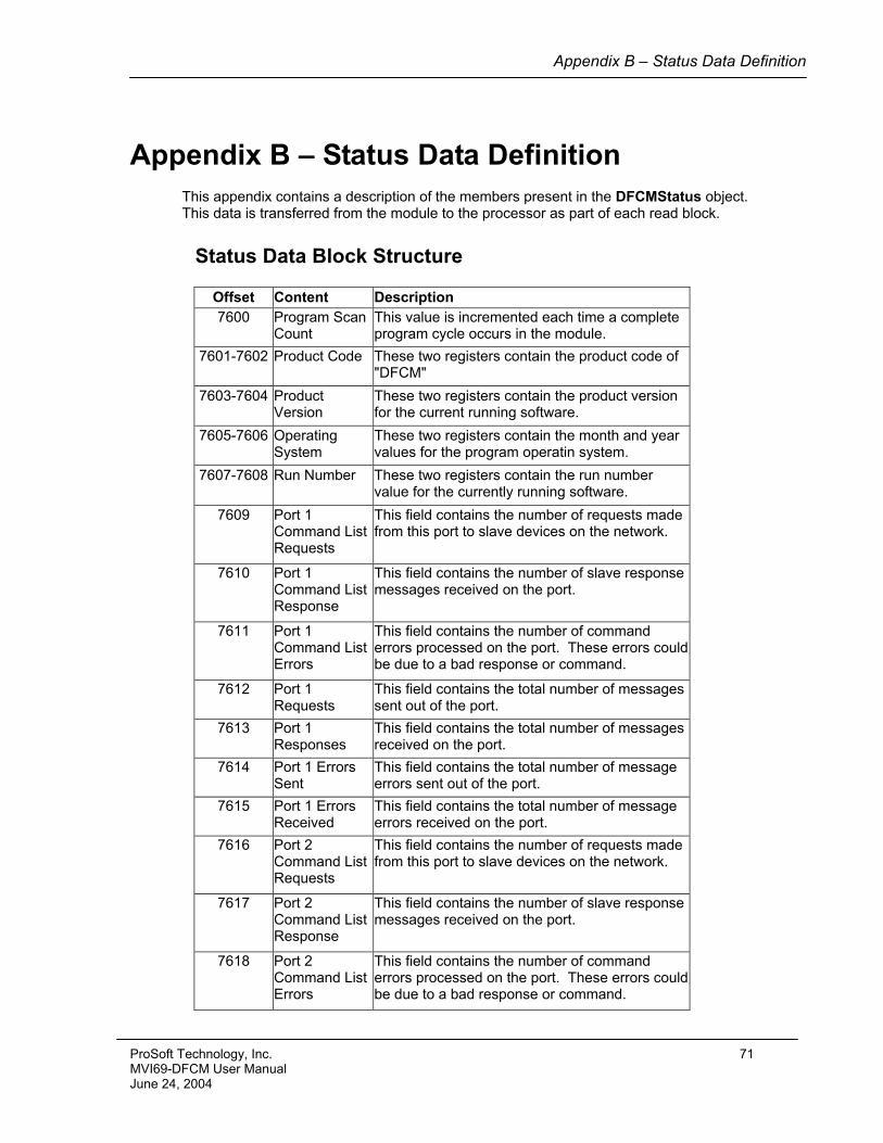
Appendix B – Status Data Definition
Appendix B – Status Data Definition This appendix contains a description of the members present in the DFCMStatus object. This data is transferred from the module to the processor as part of each read block.
Status Data Block Structure
Offset Content Description 7600 Program Scan
Count This value is incremented each time a complete program cycle occurs in the module.
7601-7602 Product Code These two registers contain the product code of "DFCM"
7603-7604 Product Version
These two registers contain the product version for the current running software.
7605-7606 Operating System
These two registers contain the month and year values for the program operatin system.
7607-7608 Run Number These two registers contain the run number value for the currently running software.
7609 Port 1 Command List Requests
This field contains the number of requests made from this port to slave devices on the network.
7610 Port 1 Command List Response
This field contains the number of slave response messages received on the port.
7611 Port 1 Command List Errors
This field contains the number of command errors processed on the port. These errors could be due to a bad response or command.
7612 Port 1 Requests
This field contains the total number of messages sent out of the port.
7613 Port 1 Responses
This field contains the total number of messages received on the port.
7614 Port 1 Errors Sent
This field contains the total number of message errors sent out of the port.
7615 Port 1 Errors Received
This field contains the total number of message errors received on the port.
7616 Port 2 Command List Requests
This field contains the number of requests made from this port to slave devices on the network.
7617 Port 2 Command List Response
This field contains the number of slave response messages received on the port.
7618 Port 2 Command List Errors
This field contains the number of command errors processed on the port. These errors could be due to a bad response or command.
ProSoft Technology, Inc. 71 MVI69-DFCM User Manual June 24, 2004
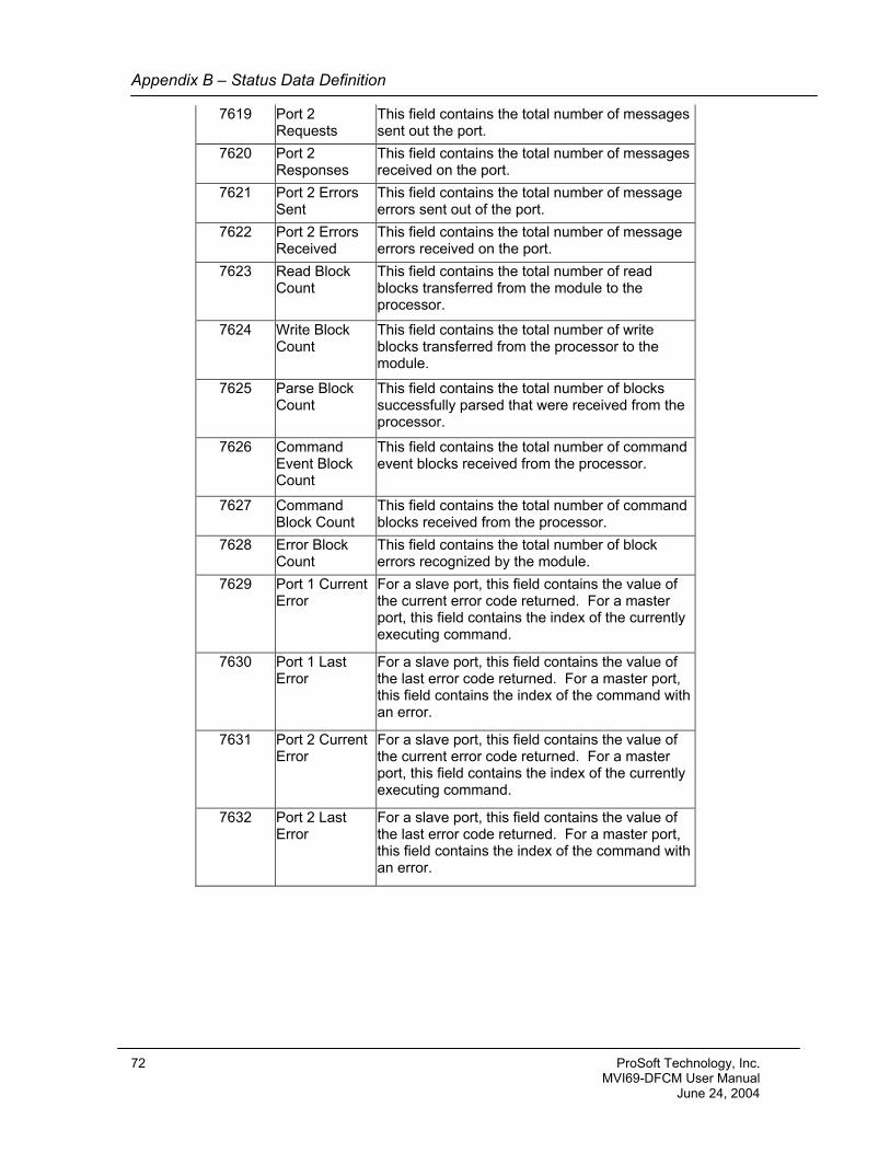
Appendix B – Status Data Definition
7619 Port 2 Requests
This field contains the total number of messages sent out the port.
7620 Port 2 Responses
This field contains the total number of messages received on the port.
7621 This field contains the total number of message errors sent out of the port.
7622 Port 2 Errors Received
This field contains the total number of message errors received on the port.
7623 Read Block Count
This field contains the total number of read blocks transferred from the module to the processor.
7624 Write Block Count
This field contains the total number of write blocks transferred from the processor to the module.
7625 Parse Block Count
This field contains the total number of blocks successfully parsed that were received from the processor.
7626 Command Event Block Count
This field contains the total number of command event blocks received from the processor.
7627 Command Block Count
This field contains the total number of command blocks received from the processor.
7628 Error Block Count
This field contains the total number of block errors recognized by the module.
7629 Port 1 Current Error
For a slave port, this field contains the value of the current error code returned. For a master port, this field contains the index of the currently executing command.
7630 Port 1 Last Error
For a slave port, this field contains the value of the last error code returned. For a master port, this field contains the index of the command with an error.
7631 Port 2 Current Error
For a slave port, this field contains the value of the current error code returned. For a master port, this field contains the index of the currently executing command.
7632 Port 2 Last Error
For a slave port, this field contains the value of the last error code returned. For a master port, this field contains the index of the command with an error.
Port 2 Errors Sent
72 ProSoft Technology, Inc. MVI69-DFCM User Manual June 24, 2004
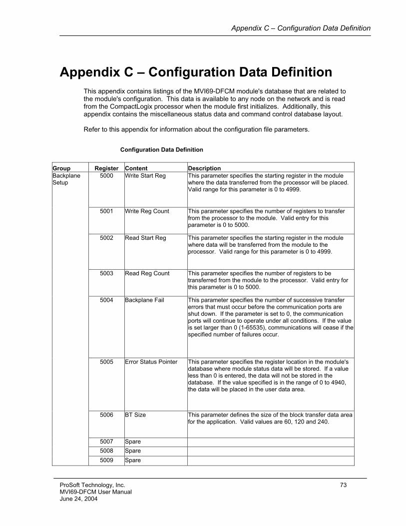
Appendix C – Configuration Data Definition
Appendix C – Configuration Data Definition This appendix contains listings of the MVI69-DFCM module's database that are related to the module's configuration. This data is available to any node on the network and is read from the CompactLogix processor when the module first initializes. Additionally, this appendix contains the miscellaneous status data and command control database layout. Refer to this appendix for information about the configuration file parameters.
Configuration Data Definition
Group Register Content Description Backplane Setup
5000 Write Start Reg This parameter specifies the starting register in the module where the data transferred from the processor will be placed. Valid range for this parameter is 0 to 4999.
5001 Write Reg Count This parameter specifies the number of registers to transfer from the processor to the module. Valid entry for this parameter is 0 to 5000.
5002 Read Start Reg This parameter specifies the starting register in the module where data will be transferred from the module to the processor. Valid range for this parameter is 0 to 4999.
5003 Read Reg Count This parameter specifies the number of registers to be transferred from the module to the processor. Valid entry for this parameter is 0 to 5000.
5004 Backplane Fail This parameter specifies the number of successive transfer errors that must occur before the communication ports are shut down. If the parameter is set to 0, the communication ports will continue to operate under all conditions. If the value is set larger than 0 (1-65535), communications will cease if the specified number of failures occur.
5005 Error Status Pointer This parameter specifies the register location in the module's database where module status data will be stored. If a value less than 0 is entered, the data will not be stored in the database. If the value specified is in the range of 0 to 4940, the data will be placed in the user data area.
5006 BT Size This parameter defines the size of the block transfer data area for the application. Valid values are 60, 120 and 240.
5007 Spare 5008 Spare 5009 Spare
ProSoft Technology, Inc. 73 MVI69-DFCM User Manual June 24, 2004
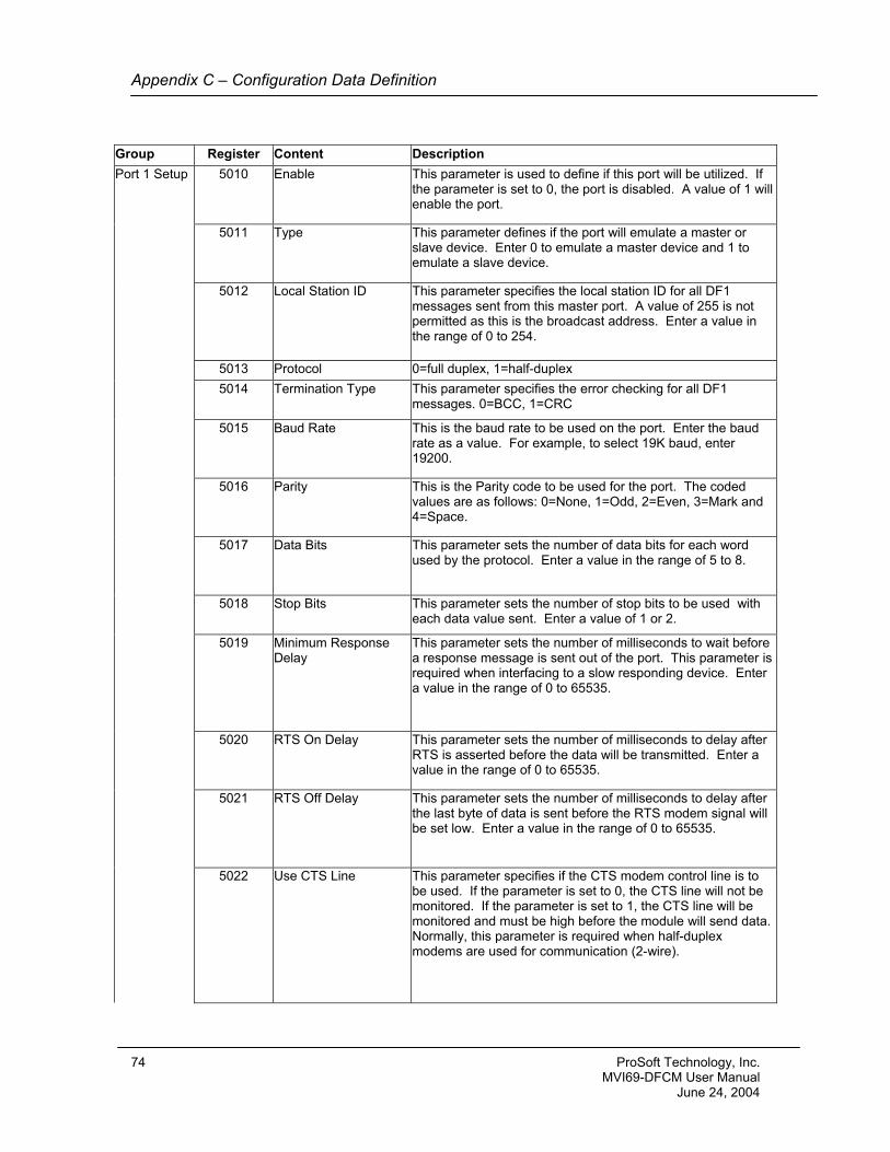
Appendix C – Configuration Data Definition
Group Register Content Description Port 1 Setup 5010 Enable This parameter is used to define if this port will be utilized. If
the parameter is set to 0, the port is disabled. A value of 1 will enable the port.
5011 Type This parameter defines if the port will emulate a master or slave device. Enter 0 to emulate a master device and 1 to emulate a slave device.
5012 Local Station ID This parameter specifies the local station ID for all DF1 messages sent from this master port. A value of 255 is not permitted as this is the broadcast address. Enter a value in the range of 0 to 254.
5013 Protocol 0=full duplex, 1=half-duplex 5014 Termination Type This parameter specifies the error checking for all DF1
messages. 0=BCC, 1=CRC
5015 Baud Rate This is the baud rate to be used on the port. Enter the baud rate as a value. For example, to select 19K baud, enter 19200.
5016 Parity This is the Parity code to be used for the port. The coded values are as follows: 0=None, 1=Odd, 2=Even, 3=Mark and 4=Space.
5017 Data Bits This parameter sets the number of data bits for each word used by the protocol. Enter a value in the range of 5 to 8.
5018 Stop Bits This parameter sets the number of stop bits to be used with each data value sent. Enter a value of 1 or 2.
5019 Minimum Response Delay
This parameter sets the number of milliseconds to wait before a response message is sent out of the port. This parameter is required when interfacing to a slow responding device. Enter a value in the range of 0 to 65535.
5020 RTS On Delay This parameter sets the number of milliseconds to delay after RTS is asserted before the data will be transmitted. Enter a value in the range of 0 to 65535.
5021 RTS Off Delay This parameter sets the number of milliseconds to delay after the last byte of data is sent before the RTS modem signal will be set low. Enter a value in the range of 0 to 65535.
5022 Use CTS Line This parameter specifies if the CTS modem control line is to be used. If the parameter is set to 0, the CTS line will not be monitored. If the parameter is set to 1, the CTS line will be monitored and must be high before the module will send data. Normally, this parameter is required when half-duplex modems are used for communication (2-wire).
74 ProSoft Technology, Inc. MVI69-DFCM User Manual June 24, 2004
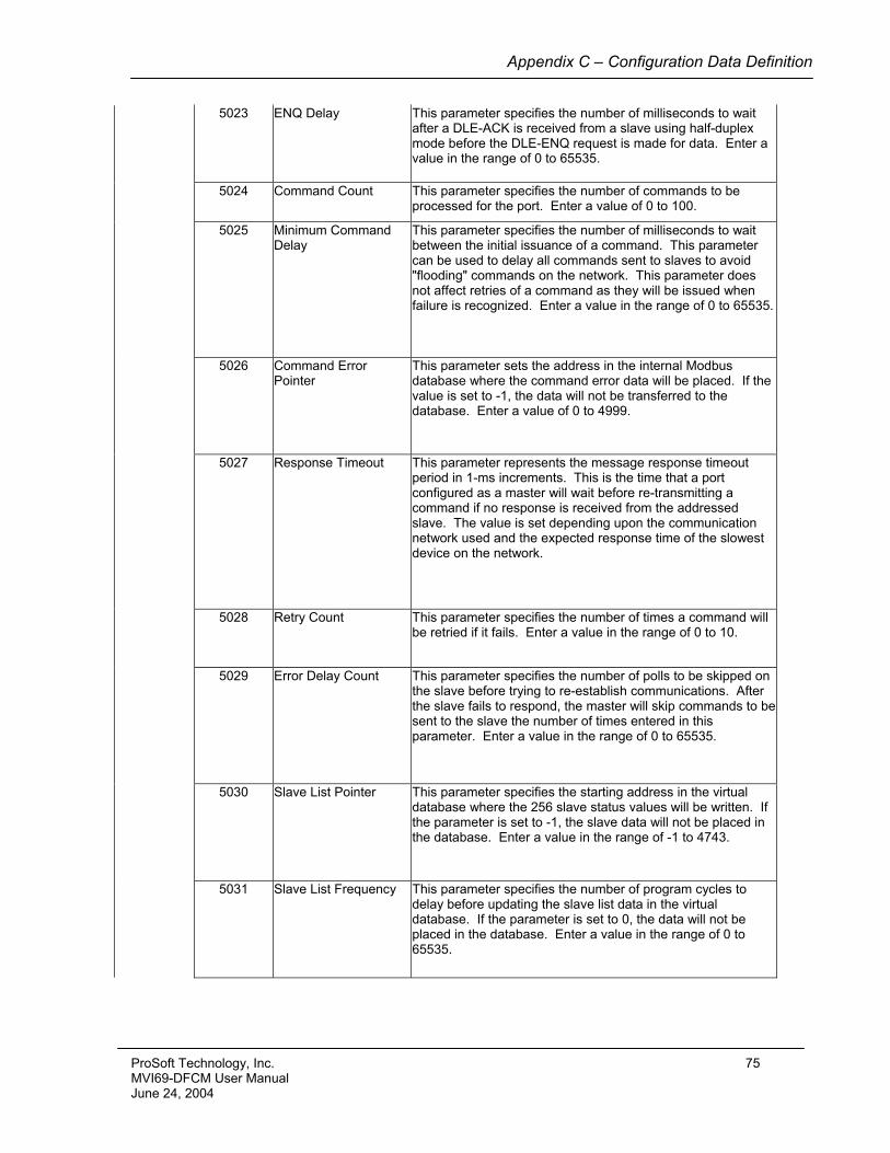
Appendix C – Configuration Data Definition
5023 ENQ Delay This parameter specifies the number of milliseconds to wait after a DLE-ACK is received from a slave using half-duplex mode before the DLE-ENQ request is made for data. Enter a value in the range of 0 to 65535.
5024 Command Count This parameter specifies the number of commands to be processed for the port. Enter a value of 0 to 100.
5025 Minimum Command Delay
This parameter specifies the number of milliseconds to wait between the initial issuance of a command. This parameter can be used to delay all commands sent to slaves to avoid "flooding" commands on the network. This parameter does not affect retries of a command as they will be issued when failure is recognized. Enter a value in the range of 0 to 65535.
5026 Command Error Pointer
This parameter sets the address in the internal Modbus database where the command error data will be placed. If the value is set to -1, the data will not be transferred to the database. Enter a value of 0 to 4999.
5027 Response Timeout This parameter represents the message response timeout period in 1-ms increments. This is the time that a port configured as a master will wait before re-transmitting a command if no response is received from the addressed slave. The value is set depending upon the communication network used and the expected response time of the slowest device on the network.
5028 Retry Count This parameter specifies the number of times a command will be retried if it fails. Enter a value in the range of 0 to 10.
5029 Error Delay Count This parameter specifies the number of polls to be skipped on the slave before trying to re-establish communications. After the slave fails to respond, the master will skip commands to be sent to the slave the number of times entered in this parameter. Enter a value in the range of 0 to 65535.
5030 Slave List Pointer This parameter specifies the starting address in the virtual database where the 256 slave status values will be written. If the parameter is set to -1, the slave data will not be placed in the database. Enter a value in the range of -1 to 4743.
5031 Slave List Frequency This parameter specifies the number of program cycles to delay before updating the slave list data in the virtual database. If the parameter is set to 0, the data will not be placed in the database. Enter a value in the range of 0 to 65535.
ProSoft Technology, Inc. 75 MVI69-DFCM User Manual June 24, 2004
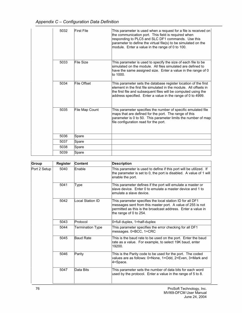
Appendix C – Configuration Data Definition
5032 First File This parameter is used when a request for a file is received on the communication port. This field is required when responding to PLC5 and SLC DF1 commands. Use this parameter to define the virtual file(s) to be simulated on the module. Enter a value in the range of 0 to 100.
5033 File Size This parameter is used to specify the size of each file to be simulated on the module. All files simulated are defined to have the same assigned size. Enter a value in the range of 0 to 1000.
5034 File Offset This parameter sets the database register location of the first element in the first file simulated in the module. All offsets in the first file and subsequent files will be computed using the address specified. Enter a value in the range of 0 to 4999.
5035 File Map Count This parameter specifies the number of specific emulated file maps that are defined for the port. The range of this parameter is 0 to 50. This parameter limits the number of map file configuration read for the port.
5036 Spare 5037 Spare 5038 Spare 5039 Spare Group Register Content Description Port 2 Setup 5040 Enable This parameter is used to define if this port will be utilized. If
the parameter is set to 0, the port is disabled. A value of 1 will enable the port.
5041 Type This parameter defines if the port will emulate a master or slave device. Enter 0 to emulate a master device and 1 to emulate a slave device.
5042 Local Station ID This parameter specifies the local station ID for all DF1 messages sent from this master port. A value of 255 is not permitted as this is the broadcast address. Enter a value in the range of 0 to 254.
5043 Protocol 0=full duplex, 1=half-duplex 5044 Termination Type This parameter specifies the error checking for all DF1
messages. 0=BCC, 1=CRC
5045 Baud Rate This is the baud rate to be used on the port. Enter the baud rate as a value. For example, to select 19K baud, enter 19200.
5046 Parity This is the Parity code to be used for the port. The coded values are as follows: 0=None, 1=Odd, 2=Even, 3=Mark and 4=Space.
5047 Data Bits This parameter sets the number of data bits for each word used by the protocol. Enter a value in the range of 5 to 8.
76 ProSoft Technology, Inc. MVI69-DFCM User Manual June 24, 2004
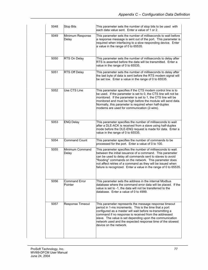
Appendix C – Configuration Data Definition
5048 Stop Bits This parameter sets the number of stop bits to be used with each data value sent. Enter a value of 1 or 2.
5049 Minimum Response Delay
This parameter sets the number of milliseconds to wait before a response message is sent out of the port. This parameter is required when interfacing to a slow responding device. Enter a value in the range of 0 to 65535.
5050 RTS On Delay This parameter sets the number of milliseconds to delay after RTS is asserted before the data will be transmitted. Enter a value in the range of 0 to 65535.
5051 RTS Off Delay This parameter sets the number of milliseconds to delay after the last byte of data is sent before the RTS modem signal will be set low. Enter a value in the range of 0 to 65535.
5052 Use CTS Line This parameter specifies if the CTS modem control line is to be used. If the parameter is set to 0, the CTS line will not be monitored. If the parameter is set to 1, the CTS line will be monitored and must be high before the module will send data. Normally, this parameter is required when half-duplex modems are used for communication (2-wire).
5053 ENQ Delay This parameter specifies the number of milliseconds to wait after a DLE-ACK is received from a slave using half-duplex mode before the DLE-ENQ request is made for data. Enter a value in the range of 0 to 65535.
5054 Command Count This parameter specifies the number of commands to be processed for the port. Enter a value of 0 to 100.
5055 Minimum Command Delay
This parameter specifies the number of milliseconds to wait between the initial issuance of a command. This parameter can be used to delay all commands sent to slaves to avoid "flooding" commands on the network. This parameter does not affect retries of a command as they will be issued when failure is recognized. Enter a value in the range of 0 to 65535.
5056 Command Error Pointer
This parameter sets the address in the internal Modbus database where the command error data will be placed. If the value is set to -1, the data will not be transferred to the database. Enter a value of 0 to 4999.
5057 Response Timeout This parameter represents the message response timeout period in 1-ms increments. This is the time that a port configured as a master will wait before re-transmitting a command if no response is received from the addressed slave. The value is set depending upon the communication network used and the expected response time of the slowest device on the network.
ProSoft Technology, Inc. 77 MVI69-DFCM User Manual June 24, 2004
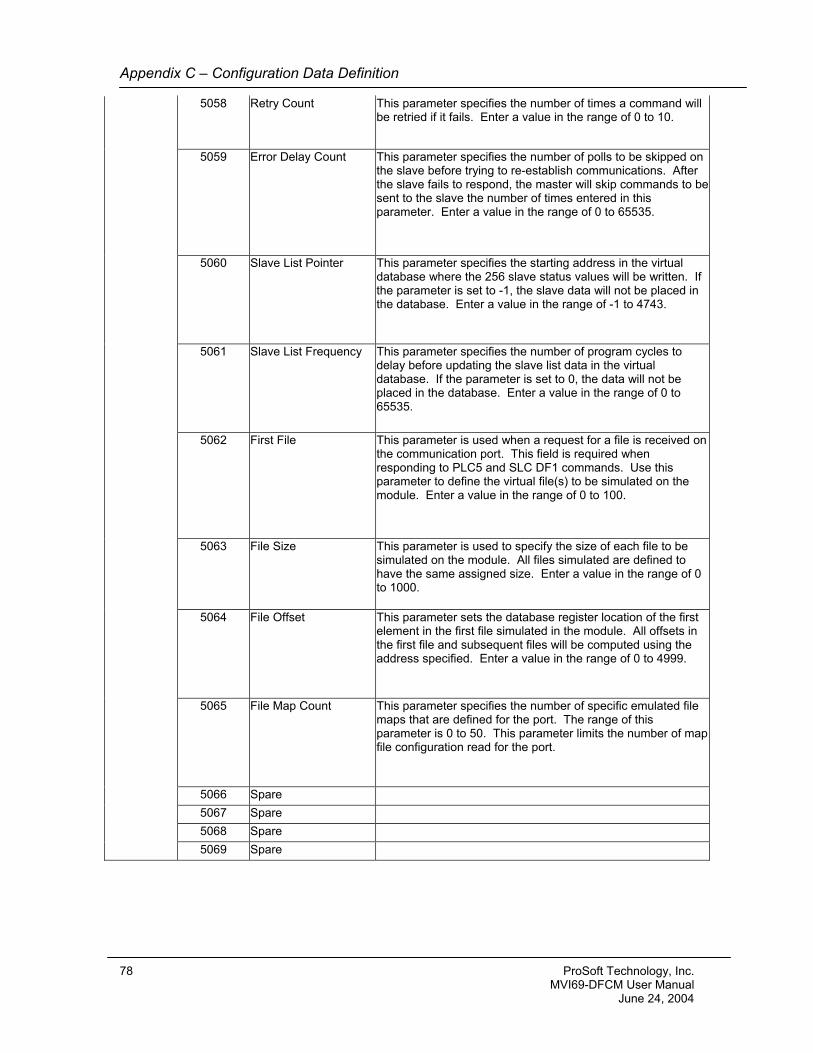
Appendix C – Configuration Data Definition
5058 Retry Count This parameter specifies the number of times a command will be retried if it fails. Enter a value in the range of 0 to 10.
5059 Error Delay Count This parameter specifies the number of polls to be skipped on the slave before trying to re-establish communications. After the slave fails to respond, the master will skip commands to be sent to the slave the number of times entered in this parameter. Enter a value in the range of 0 to 65535.
5060 Slave List Pointer This parameter specifies the starting address in the virtual database where the 256 slave status values will be written. If the parameter is set to -1, the slave data will not be placed in the database. Enter a value in the range of -1 to 4743.
5061 Slave List Frequency This parameter specifies the number of program cycles to delay before updating the slave list data in the virtual database. If the parameter is set to 0, the data will not be placed in the database. Enter a value in the range of 0 to 65535.
5062 First File This parameter is used when a request for a file is received on the communication port. This field is required when responding to PLC5 and SLC DF1 commands. Use this parameter to define the virtual file(s) to be simulated on the module. Enter a value in the range of 0 to 100.
5063 File Size This parameter is used to specify the size of each file to be simulated on the module. All files simulated are defined to have the same assigned size. Enter a value in the range of 0 to 1000.
5064 File Offset This parameter sets the database register location of the first element in the first file simulated in the module. All offsets in the first file and subsequent files will be computed using the address specified. Enter a value in the range of 0 to 4999.
5065 File Map Count This parameter specifies the number of specific emulated file maps that are defined for the port. The range of this parameter is 0 to 50. This parameter limits the number of map file configuration read for the port.
5066 Spare 5067 Spare 5068 Spare 5069 Spare
78 ProSoft Technology, Inc. MVI69-DFCM User Manual June 24, 2004
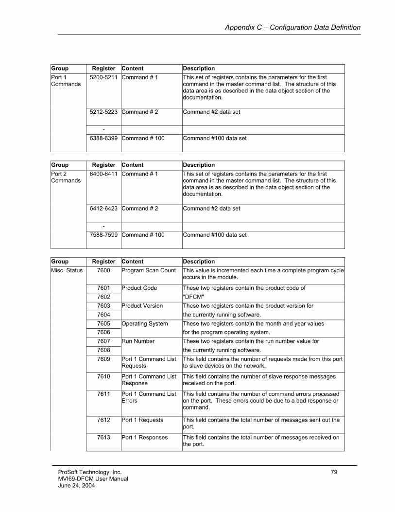
Appendix C – Configuration Data Definition
Group Register Content Description Port 1 Commands
5200-5211 Command # 1 This set of registers contains the parameters for the first command in the master command list. The structure of this data area is as described in the data object section of the documentation.
5212-5223 Command # 2 Command #2 data set
- 6388-6399 Command # 100 Command #100 data set
Group Register Content Description Port 2 Commands
6400-6411 Command # 1 This set of registers contains the parameters for the first command in the master command list. The structure of this data area is as described in the data object section of the documentation.
6412-6423 Command # 2 Command #2 data set
- 7588-7599 Command # 100 Command #100 data set
Group Register Content Description Misc. Status 7600 Program Scan Count This value is incremented each time a complete program cycle
occurs in the module.
7601 Product Code These two registers contain the product code of 7602 "DFCM" 7603 Product Version These two registers contain the product version for 7604 the currently running software. 7605 Operating System These two registers contain the month and year values 7606 for the program operating system. 7607 Run Number These two registers contain the run number value for 7608 the currently running software. 7609 Port 1 Command List
Requests This field contains the number of requests made from this port to slave devices on the network.
7610 Port 1 Command List Response
This field contains the number of slave response messages received on the port.
7611 Port 1 Command List Errors
This field contains the number of command errors processed on the port. These errors could be due to a bad response or command.
7612 Port 1 Requests This field contains the total number of messages sent out the port.
7613 Port 1 Responses This field contains the total number of messages received on the port.
ProSoft Technology, Inc. 79 MVI69-DFCM User Manual June 24, 2004
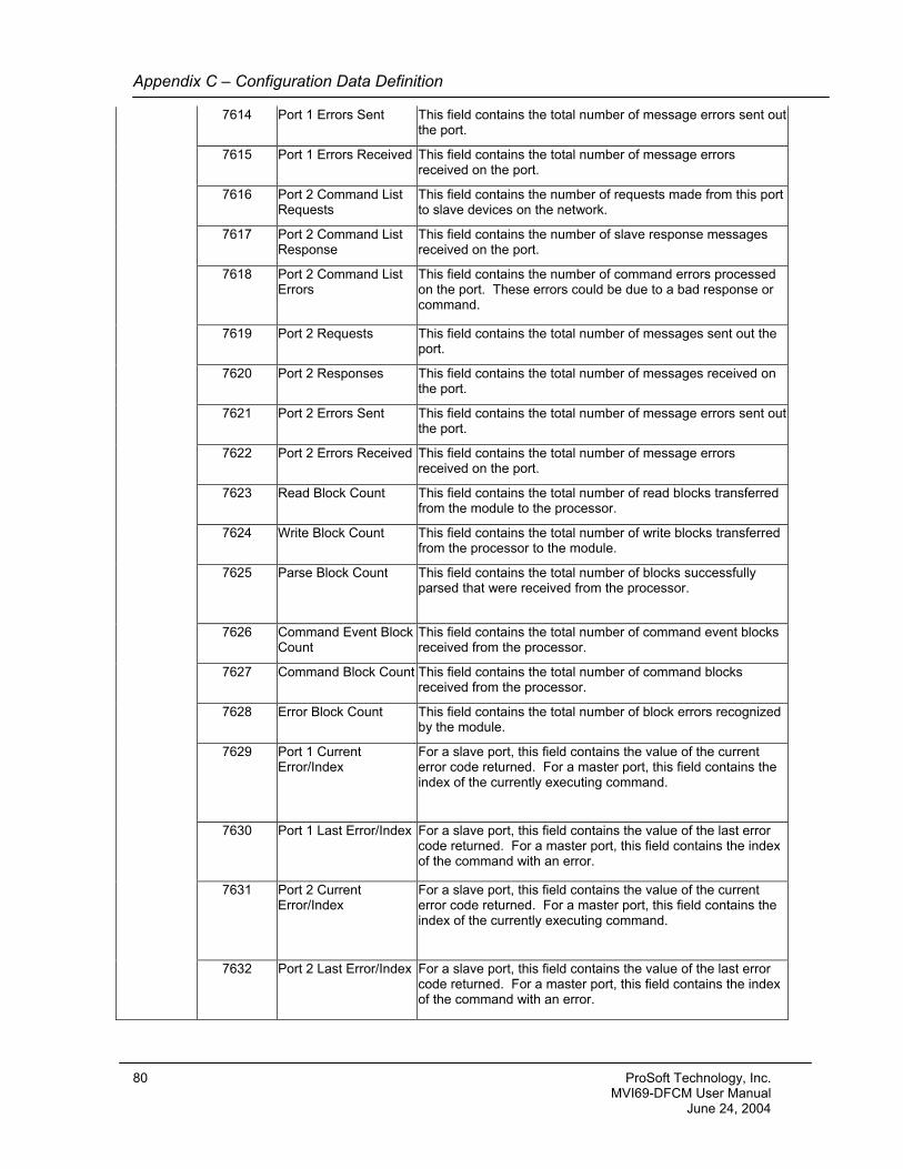
Appendix C – Configuration Data Definition
7614 Port 1 Errors Sent This field contains the total number of message errors sent out the port.
7615 Port 1 Errors Received This field contains the total number of message errors received on the port.
7616 Port 2 Command List Requests
This field contains the number of requests made from this port to slave devices on the network.
7617 Port 2 Command List Response
This field contains the number of slave response messages received on the port.
7618 Port 2 Command List Errors
This field contains the number of command errors processed on the port. These errors could be due to a bad response or command.
7619 Port 2 Requests This field contains the total number of messages sent out the port.
7620 Port 2 Responses This field contains the total number of messages received on the port.
7621 Port 2 Errors Sent This field contains the total number of message errors sent out the port.
7622 Port 2 Errors Received This field contains the total number of message errors received on the port.
7623 Read Block Count This field contains the total number of read blocks transferred from the module to the processor.
7624 Write Block Count This field contains the total number of write blocks transferred from the processor to the module.
7625 Parse Block Count This field contains the total number of blocks successfully parsed that were received from the processor.
7626 Command Event Block Count
This field contains the total number of command event blocks received from the processor.
7627 Command Block Count This field contains the total number of command blocks received from the processor.
7628 Error Block Count This field contains the total number of block errors recognized by the module.
7629 Port 1 Current Error/Index
For a slave port, this field contains the value of the current error code returned. For a master port, this field contains the index of the currently executing command.
7630 Port 1 Last Error/Index For a slave port, this field contains the value of the last error code returned. For a master port, this field contains the index of the command with an error.
7631 Port 2 Current Error/Index
For a slave port, this field contains the value of the current error code returned. For a master port, this field contains the index of the currently executing command.
7632 Port 2 Last Error/Index For a slave port, this field contains the value of the last error code returned. For a master port, this field contains the index of the command with an error.
80 ProSoft Technology, Inc. MVI69-DFCM User Manual June 24, 2004
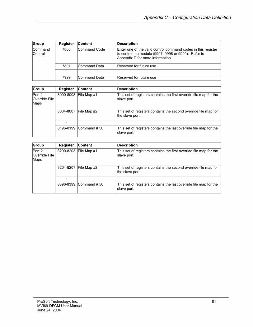
Appendix C – Configuration Data Definition
Group Register Content Description Command Control
7800 Command Code Enter one of the valid control command codes in this register to control the module (9997, 9998 or 9999). Refer to Appendix D for more information.
7801 Command Data Reserved for future use - - 7999 Command Data Reserved for future use
Group Register Content Description Port 1 Override File Maps
8000-8003 File Map #1 This set of registers contains the first override file map for the slave port.
8004-8007 File Map #2 This set of registers contains the second override file map for the slave port.
- 8196-8199 Command # 50 This set of registers contains the last override file map for the
slave port.
Group Register Content Description Port 2 Override File Maps
8200-8203 File Map #1 This set of registers contains the first override file map for the slave port.
8204-8207 File Map #2 This set of registers contains the second override file map for the slave port.
- 8396-8399 Command # 50 This set of registers contains the last override file map for the
slave port.
ProSoft Technology, Inc. 81 MVI69-DFCM User Manual June 24, 2004

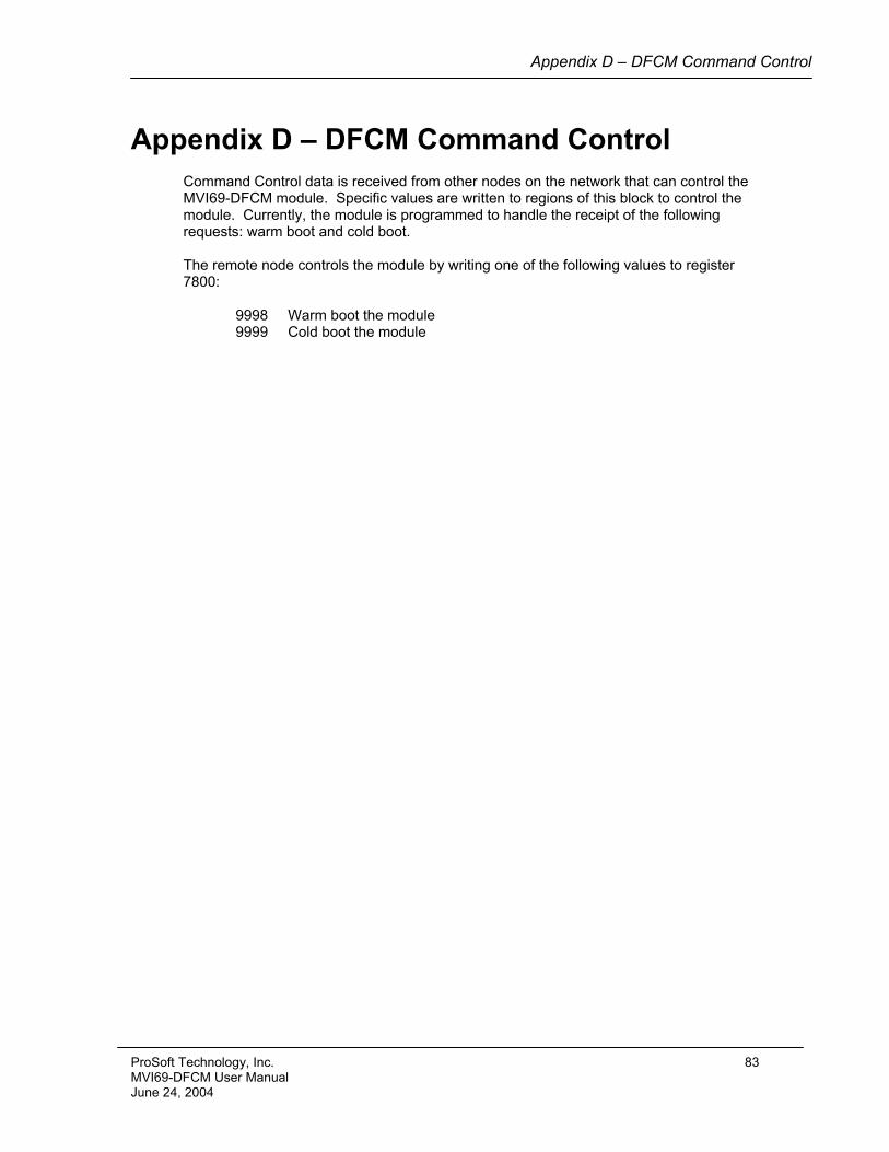
Appendix D – DFCM Command Control
Appendix D – DFCM Command Control Command Control data is received from other nodes on the network that can control the MVI69-DFCM module. Specific values are written to regions of this block to control the module. Currently, the module is programmed to handle the receipt of the following requests: warm boot and cold boot. The remote node controls the module by writing one of the following values to register 7800:
9998 Warm boot the module 9999 Cold boot the module
ProSoft Technology, Inc. 83 MVI69-DFCM User Manual June 24, 2004

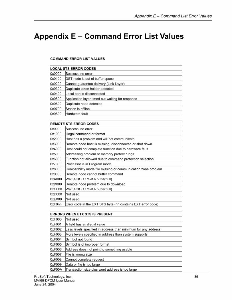
Appendix E – Command List Error Values
Appendix E – Command Error List Values
COMMAND ERROR LIST VALUES LOCAL STS ERROR CODES 0x0000 Success, no error 0x0100 DST node is out of buffer space 0x0200 Cannot guarantee delivery (Link Layer) 0x0300 Duplicate token holder detected 0x0400 Local port is disconnected 0x0500 Application layer timed out waiting for response 0x0600 Duplicate node detected 0x0700 Station is offline 0x0800 Hardware fault REMOTE STS ERROR CODES 0x0000 Success, no error 0x1000 Illegal command or format 0x2000 Host has a problem and will not communicate 0x3000 Remote node host is missing, disconnected or shut down 0x4000 Host could not complete function due to hardware fault 0x5000 Addressing problem or memory protect rungs 0x6000 Function not allowed due to command protection selection 0x7000 Processor is in Program mode 0x8000 Compatibility mode file missing or communication zone problem 0x9000 Remote node cannot buffer command 0xA000 Wait ACK (1775-KA buffer full) 0xB000 Remote node problem due to download 0xC000 Wait ACK (1775-KA buffer full) 0xD000 Not used 0xE000 Not used 0xF0nn Error code in the EXT STS byte (nn contains EXT error code) ERRORS WHEN ETX STS IS PRESENT 0xF000 Not used 0xF001 A field has an illegal value 0xF002 Less levels specified in address than minimum for any address 0xF003 More levels specified in address than system supports 0xF004 Symbol not found 0xF005 Symbol is of improper format 0xF006 Address does not point to something usable 0xF007 File is wrong size 0xF008 Cannot complete request 0xF009 Data or file is too large 0xF00A Transaction size plus word address is too large
ProSoft Technology, Inc. 85 MVI69-DFCM User Manual June 24, 2004
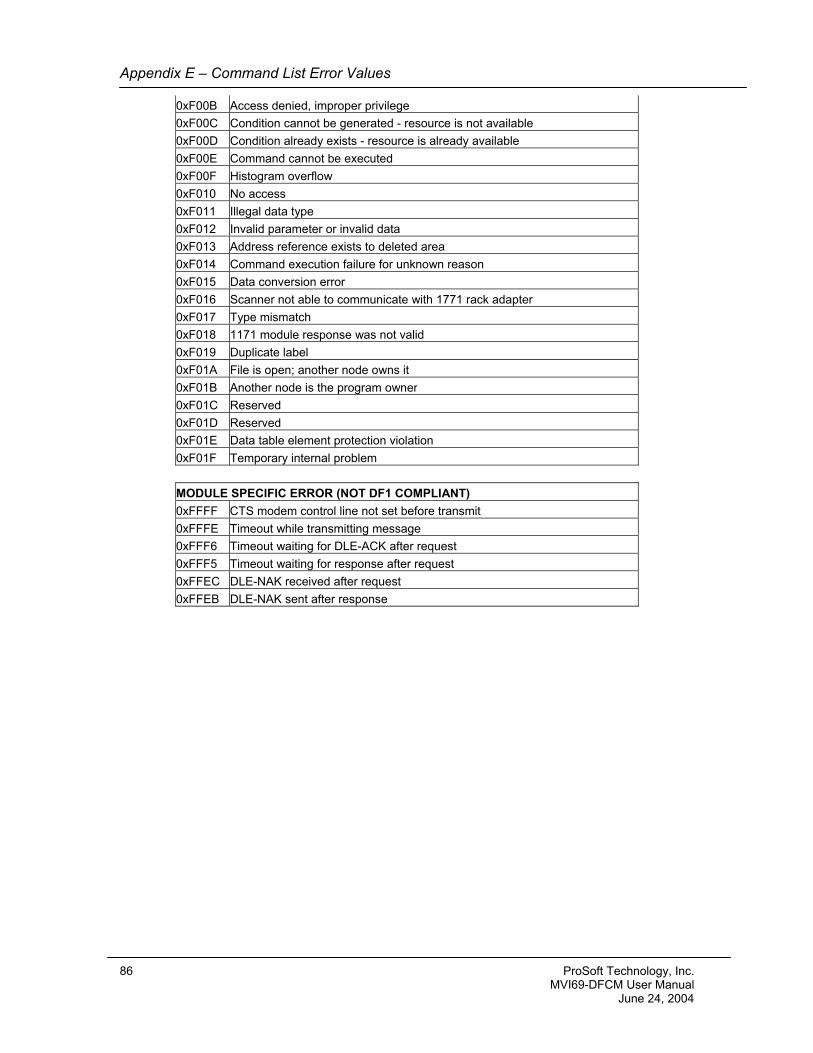
Appendix E – Command List Error Values
0xF00B Access denied, improper privilege 0xF00C Condition cannot be generated - resource is not available 0xF00D Condition already exists - resource is already available 0xF00E Command cannot be executed 0xF00F Histogram overflow 0xF010 No access 0xF011 Illegal data type 0xF012 Invalid parameter or invalid data 0xF013 Address reference exists to deleted area 0xF014 Command execution failure for unknown reason 0xF015 Data conversion error 0xF016 Scanner not able to communicate with 1771 rack adapter 0xF017 Type mismatch 0xF018 1171 module response was not valid 0xF019 Duplicate label 0xF01A File is open; another node owns it 0xF01B Another node is the program owner 0xF01C Reserved 0xF01D Reserved 0xF01E Data table element protection violation 0xF01F Temporary internal problem MODULE SPECIFIC ERROR (NOT DF1 COMPLIANT) 0xFFFF CTS modem control line not set before transmit 0xFFFE Timeout while transmitting message 0xFFF6 Timeout waiting for DLE-ACK after request 0xFFF5 Timeout waiting for response after request 0xFFEC DLE-NAK received after request 0xFFEB DLE-NAK sent after response
86 ProSoft Technology, Inc. MVI69-DFCM User Manual June 24, 2004
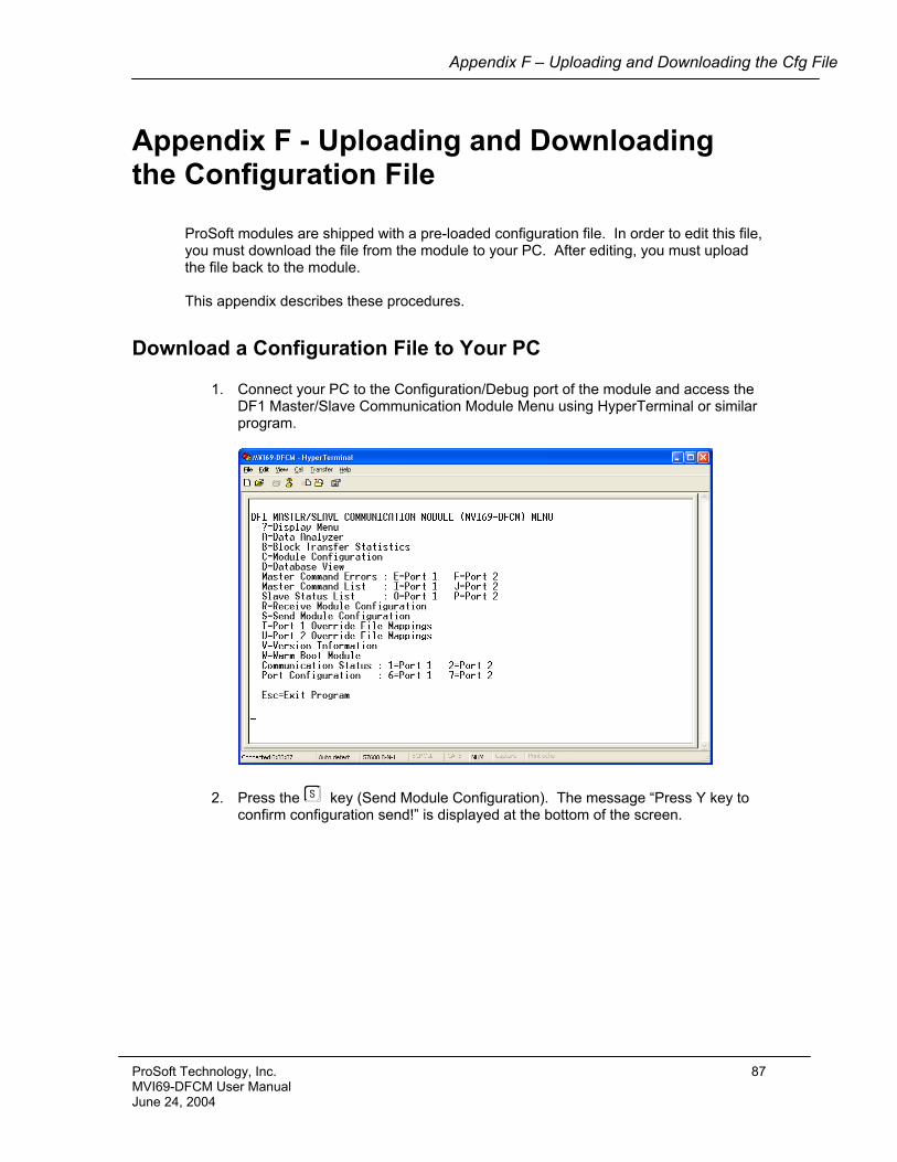
Appendix F – Uploading and Downloading the Cfg File
Appendix F - Uploading and Downloading the Configuration File
ProSoft modules are shipped with a pre-loaded configuration file. In order to edit this file, you must download the file from the module to your PC. After editing, you must upload the file back to the module. This appendix describes these procedures.
Download a Configuration File to Your PC
1. Connect your PC to the Configuration/Debug port of the module and access the DF1 Master/Slave Communication Module Menu using HyperTerminal or similar program.
2. Press the S key (Send Module Configuration). The message “Press Y key to confirm configuration send!” is displayed at the bottom of the screen.
ProSoft Technology, Inc. 87 MVI69-DFCM User Manual June 24, 2004
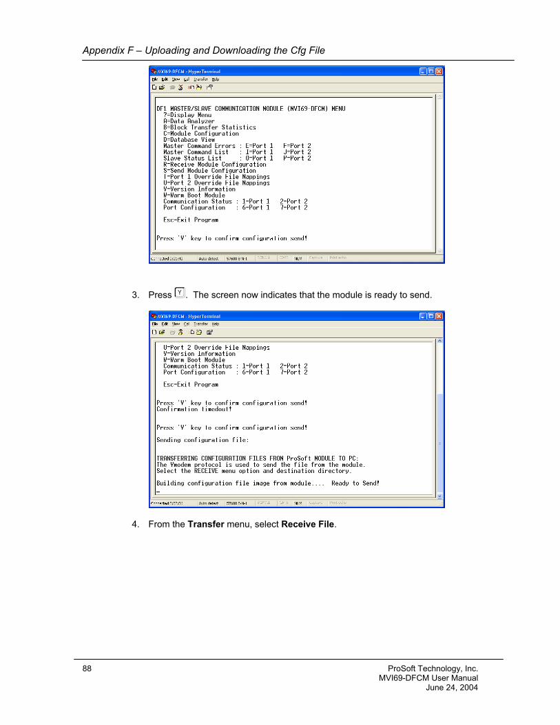
Appendix F – Uploading and Downloading the Cfg File
3. Press Y. The screen now indicates that the module is ready to send.
4. From the Transfer menu, select Receive File.
88 ProSoft Technology, Inc. MVI69-DFCM User Manual June 24, 2004
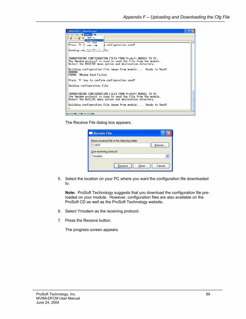
Appendix F – Uploading and Downloading the Cfg File
The Receive File dialog box appears:
5. Select the location on your PC where you want the configuration file downloaded to. Note: ProSoft Technology suggests that you download the configuration file pre-loaded on your module. However, configuration files are also available on the ProSoft CD as well as the ProSoft Technology website.
6. Select Ymodem as the receiving protocol.
7. Press the Receive button.
The progress screen appears.
ProSoft Technology, Inc. 89 MVI69-DFCM User Manual June 24, 2004
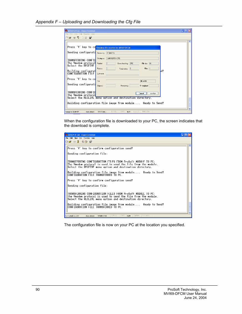
Appendix F – Uploading and Downloading the Cfg File
When the configuration file is downloaded to your PC, the screen indicates that the download is complete.
The configuration file is now on your PC at the location you specified.
90 ProSoft Technology, Inc. MVI69-DFCM User Manual June 24, 2004
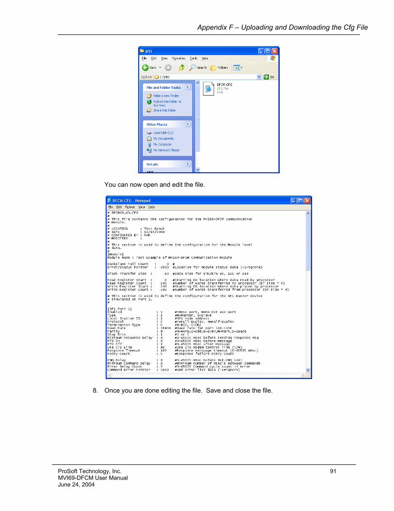
Appendix F – Uploading and Downloading the Cfg File
You can now open and edit the file.
8. Once you are done editing the file. Save and close the file.
ProSoft Technology, Inc. 91 MVI69-DFCM User Manual June 24, 2004
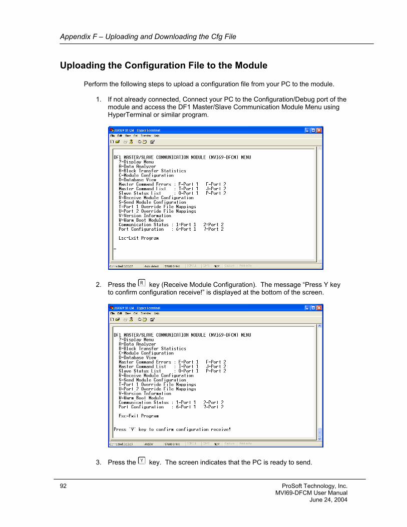
Appendix F – Uploading and Downloading the Cfg File
Uploading the Configuration File to the Module Perform the following steps to upload a configuration file from your PC to the module.
1. If not already connected, Connect your PC to the Configuration/Debug port of the module and access the DF1 Master/Slave Communication Module Menu using HyperTerminal or similar program.
2. Press the R key (Receive Module Configuration). The message “Press Y key to confirm configuration receive!” is displayed at the bottom of the screen.
3. Press the Y key. The screen indicates that the PC is ready to send.
92 ProSoft Technology, Inc. MVI69-DFCM User Manual June 24, 2004
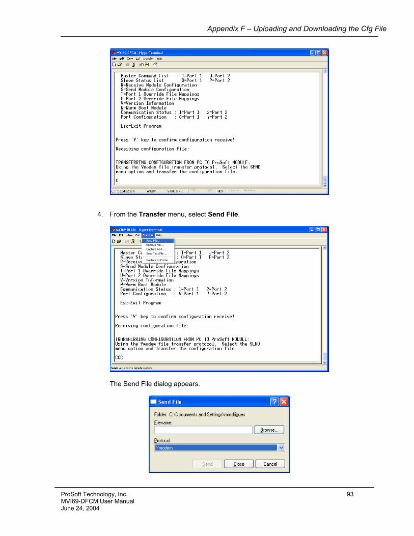
Appendix F – Uploading and Downloading the Cfg File
4. From the Transfer menu, select Send File.
The Send File dialog appears.
ProSoft Technology, Inc. 93 MVI69-DFCM User Manual June 24, 2004
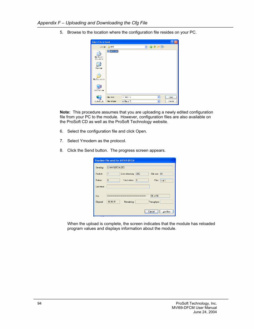
Appendix F – Uploading and Downloading the Cfg File
5. Browse to the location where the configuration file resides on your PC.
Note: This procedure assumes that you are uploading a newly edited configuration file from your PC to the module. However, configuration files are also available on the ProSoft CD as well as the ProSoft Technology website.
6. Select the configuration file and click Open.
7. Select Ymodem as the protocol.
8. Click the Send button. The progress screen appears.
When the upload is complete, the screen indicates that the module has reloaded program values and displays information about the module.
94 ProSoft Technology, Inc. MVI69-DFCM User Manual June 24, 2004
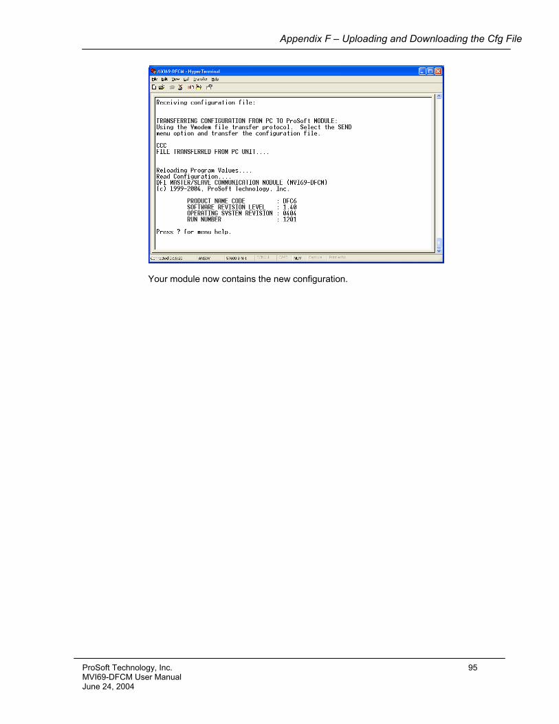
Appendix F – Uploading and Downloading the Cfg File
Your module now contains the new configuration.
ProSoft Technology, Inc. 95 MVI69-DFCM User Manual June 24, 2004

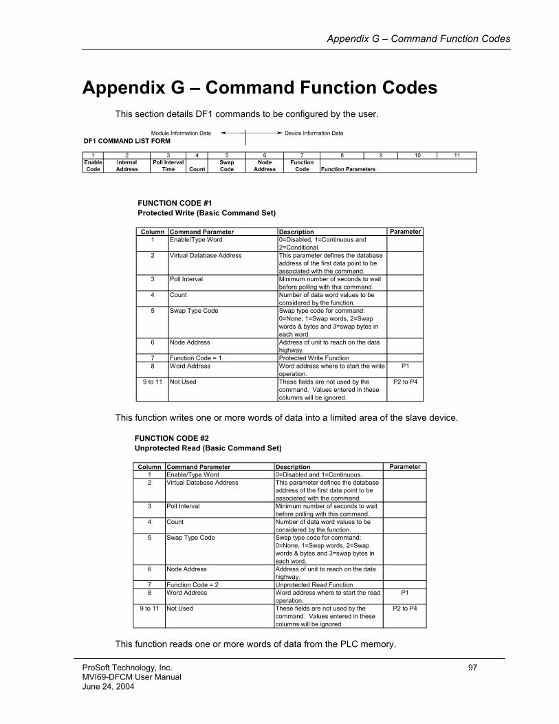
Appendix G – Command Function Codes
Appendix G – Command Function Codes This section details DF1 commands to be configured by the user.
Module Information Data Device Information DataDF1 COMMAND LIST FORM
1 2 3 4 5 6 7 8 9 10 11Enable Internal Poll Interval Swap Node FunctionCode Address Time Count Code Address Code Function Parameters
FUNCTION CODE #1Protected Write (Basic Command Set)
Column Command Parameter Description Parameter1 Enable/Type Word 0=Disabled, 1=Continuous and
2=Conditional.2 Virtual Database Address This parameter defines the database
address of the first data point to be associated with the command.
3 Poll Interval Minimum number of seconds to wait before polling with this command.
4 Count Number of data word values to be considered by the function.
5 Swap Type Code Swap type code for command: 0=None, 1=Swap words, 2=Swap words & bytes and 3=swap bytes in each word.
6 Node Address Address of unit to reach on the data highway.
7 Function Code = 1 Protected Write Function8 Word Address Word address where to start the write
operation.P1
9 to 11 Not Used These fields are not used by the command. Values entered in these columns will be ignored.
P2 to P4
This function writes one or more words of data into a limited area of the slave device.
FUNCTION CODE #2Unprotected Read (Basic Command Set)
Column Command Parameter Description Parameter1 Enable/Type Word 0=Disabled and 1=Continuous.2 Virtual Database Address This parameter defines the database
address of the first data point to be associated with the command.
3 Poll Interval Minimum number of seconds to wait before polling with this command.
4 Count Number of data word values to be considered by the function.
5 Swap Type Code Swap type code for command: 0=None, 1=Swap words, 2=Swap words & bytes and 3=swap bytes in each word.
6 Node Address Address of unit to reach on the data highway.
7 Function Code = 2 Unprotected Read Function8 Word Address Word address where to start the read
operation.P1
9 to 11 Not Used These fields are not used by the command. Values entered in these columns will be ignored.
P2 to P4
This function reads one or more words of data from the PLC memory.
ProSoft Technology, Inc. 97 MVI69-DFCM User Manual June 24, 2004
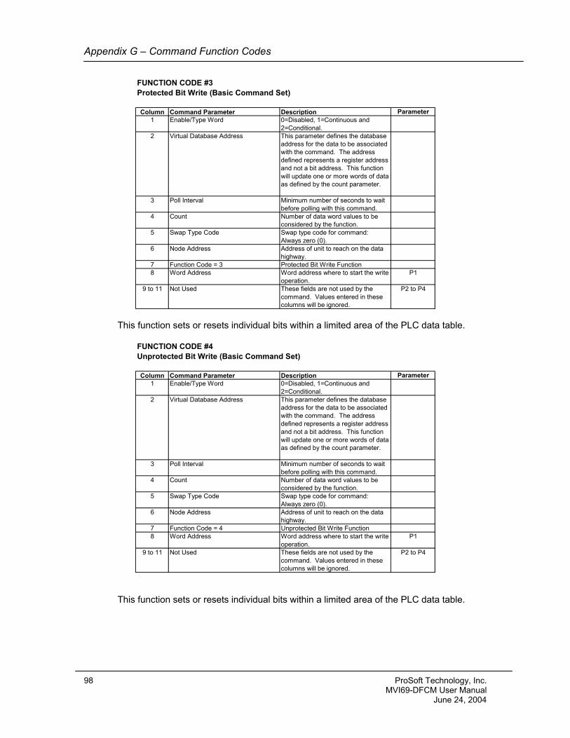
Appendix G – Command Function Codes
FUNCTION CODE #3Protected Bit Write (Basic Command Set)
Column Command Parameter Description Parameter1 Enable/Type Word 0=Disabled, 1=Continuous and
2=Conditional.2 Virtual Database Address This parameter defines the database
address for the data to be associated with the command. The address defined represents a register address and not a bit address. This function will update one or more words of data as defined by the count parameter.
3 Poll Interval Minimum number of seconds to wait before polling with this command.
4 Count Number of data word values to be considered by the function.
5 Swap Type Code Swap type code for command: Always zero (0).
6 Node Address Address of unit to reach on the data highway.
7 Function Code = 3 Protected Bit Write Function8 Word Address Word address where to start the write
operation.P1
9 to 11 Not Used These fields are not used by the command. Values entered in these columns will be ignored.
P2 to P4
This function sets or resets individual bits within a limited area of the PLC data table.
FUNCTION CODE #4Unprotected Bit Write (Basic Command Set)
Column Command Parameter Description Parameter1 Enable/Type Word 0=Disabled, 1=Continuous and
2=Conditional.2 Virtual Database Address This parameter defines the database
address for the data to be associated with the command. The address defined represents a register address and not a bit address. This function will update one or more words of data as defined by the count parameter.
3 Poll Interval Minimum number of seconds to wait before polling with this command.
4 Count Number of data word values to be considered by the function.
5 Swap Type Code Swap type code for command: Always zero (0).
6 Node Address Address of unit to reach on the data highway.
7 Function Code = 4 Unprotected Bit Write Function8 Word Address Word address where to start the write
operation.P1
9 to 11 Not Used These fields are not used by the command. Values entered in these columns will be ignored.
P2 to P4
This function sets or resets individual bits within a limited area of the PLC data table.
98 ProSoft Technology, Inc. MVI69-DFCM User Manual June 24, 2004
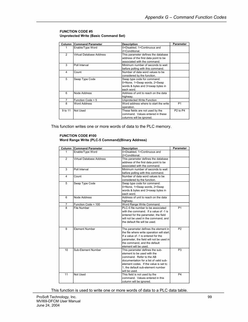
Appendix G – Command Function Codes
FUNCTION CODE #5Unprotected Write (Basic Command Set)
Column Command Parameter Description Parameter1 Enable/Type Word 0=Disabled, 1=Continuous and
2=Conditional.2 Virtual Database Address This parameter defines the database
address of the first data point to be associated with the command.
3 Poll Interval Minimum number of seconds to wait before polling with this command.
4 Count Number of data word values to be considered by the function.
5 Swap Type Code Swap type code for command: 0=None, 1=Swap words, 2=Swap words & bytes and 3=swap bytes in each word.
6 Node Address Address of unit to reach on the data highway.
7 Function Code = 5 Unprotected Write Function8 Word Address Word address where to start the write
operation.P1
9 to 11 Not Used These fields are not used by the command. Values entered in these columns will be ignored.
P2 to P4
This function writes one or more words of data to the PLC memory.
FUNCTION CODE #100Word Range Write (PLC-5 Command)(Binary Address)
Column Command Parameter Description Parameter1 Enable/Type Word 0=Disabled, 1=Continuous and
2=Conditional.2 Virtual Database Address This parameter defines the database
address of the first data point to be associated with the command.
3 Poll Interval Minimum number of seconds to wait before polling with this command.
4 Count Number of data word values to be considered by the function.
5 Swap Type Code Swap type code for command: 0=None, 1=Swap words, 2=Swap words & bytes and 3=swap bytes in each word.
6 Node Address Address of unit to reach on the data highway.
7 Function Code = 100 Word Range Write Command.8 File Number PLC-5 file number to be associated
with the command. If a value of -1 is entered for the parameter, the field will not be used in the command, and the default file will be used.
P1
9 Element Number The parameter defines the element in the file where write operation will start. If a value of -1 is entered for the parameter, the field will not be used in the command, and the default element will be used.
P2
10 Sub-Element Number This parameter defines the sub-element to be used with the command. Refer to the AB documentation for a list of valid sub-element codes. If the value is set to -1, the default sub-element number will be used.
P3
11 Not Used This field is not used by the command. Values entered in this column will be ignored.
P4
This function is used to write one or more words of data to a PLC data table.
ProSoft Technology, Inc. 99 MVI69-DFCM User Manual June 24, 2004
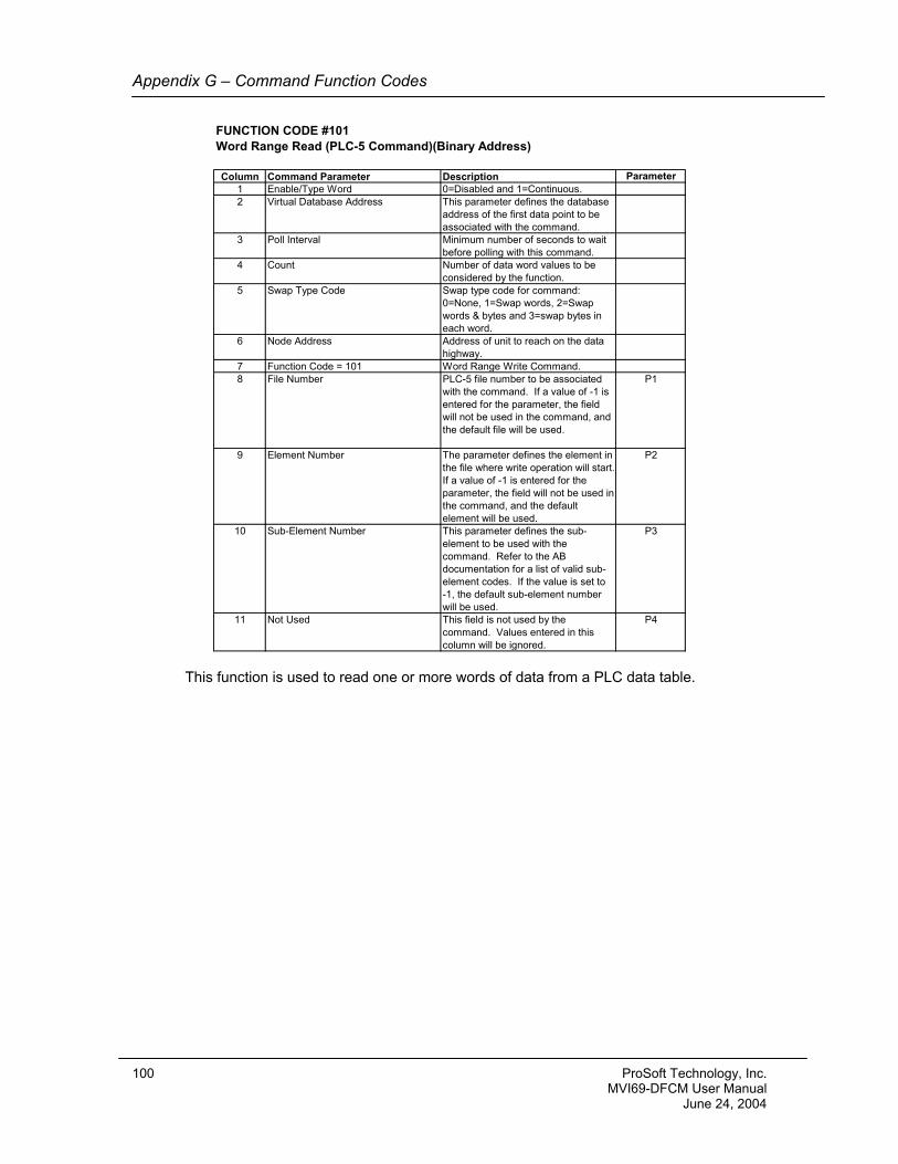
Appendix G – Command Function Codes
FUNCTION CODE #101Word Range Read (PLC-5 Command)(Binary Address)
Column Command Parameter Description Parameter1 Enable/Type Word 0=Disabled and 1=Continuous.2 Virtual Database Address This parameter defines the database
address of the first data point to be associated with the command.
3 Poll Interval Minimum number of seconds to wait before polling with this command.
4 Count Number of data word values to be considered by the function.
5 Swap Type Code Swap type code for command: 0=None, 1=Swap words, 2=Swap words & bytes and 3=swap bytes in each word.
6 Node Address Address of unit to reach on the data highway.
7 Function Code = 101 Word Range Write Command.8 File Number PLC-5 file number to be associated
with the command. If a value of -1 is entered for the parameter, the field will not be used in the command, and the default file will be used.
P1
9 Element Number The parameter defines the element in the file where write operation will start. If a value of -1 is entered for the parameter, the field will not be used in the command, and the default element will be used.
P2
10 Sub-Element Number This parameter defines the sub-element to be used with the command. Refer to the AB documentation for a list of valid sub-element codes. If the value is set to -1, the default sub-element number will be used.
P3
11 Not Used This field is not used by the command. Values entered in this column will be ignored.
P4
This function is used to read one or more words of data from a PLC data table.
100 ProSoft Technology, Inc. MVI69-DFCM User Manual June 24, 2004
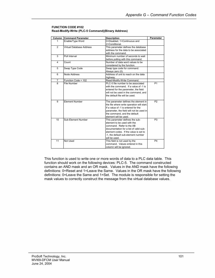
Appendix G – Command Function Codes
FUNCTION CODE #102Read-Modify-Write (PLC-5 Command)(Binary Address)
Column Command Parameter Description Parameter1 Enable/Type Word 0=Disabled, 1=Continuous and
2=Conditional.2 Virtual Database Address This parameter defines the database
address for the data to be associated with the command.
3 Poll Interval Minimum number of seconds to wait before polling with this command.
4 Count Number of data word values to be considered by the function.
5 Swap Type Code Swap type code for command: Always zero (0).
6 Node Address Address of unit to reach on the data highway.
7 Function Code = 102 Read-Modify-Write Command.8 File Number PLC-5 file number to be associated
with the command. If a value of -1 is entered for the parameter, the field will not be used in the command, and the default file will be used.
P1
9 Element Number The parameter defines the element in the file where write operation will start. If a value of -1 is entered for the parameter, the field will not be used in the command, and the default element will be used.
P2
10 Sub-Element Number This parameter defines the sub-element to be used with the command. Refer to the AB documentation for a list of valid sub-element codes. If the value is set to -1, the default sub-element number will be used.
P3
11 Not Used This field is not used by the command. Values entered in this column will be ignored.
P4
This function is used to write one or more words of data to a PLC data table. This function should work on the following devices: PLC-5. The command constructed contains an AND mask and an OR mask. Values in the AND mask have the following definitions: 0=Reset and 1=Leave the Same. Values in the OR mask have the following definitions: 0=Leave the Same and 1=Set. The module is responsible for setting the mask values to correctly construct the message from the virtual database values.
ProSoft Technology, Inc. 101 MVI69-DFCM User Manual June 24, 2004
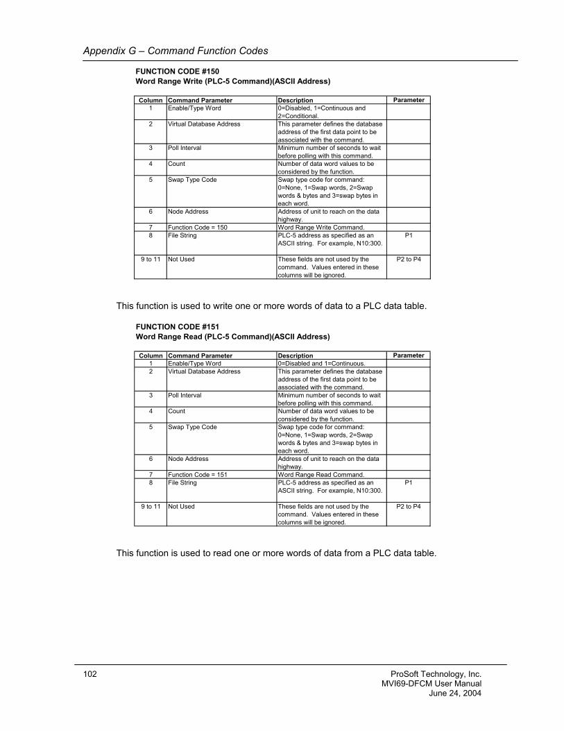
Appendix G – Command Function Codes
FUNCTION CODE #150Word Range Write (PLC-5 Command)(ASCII Address)
Column Command Parameter Description Parameter1 Enable/Type Word 0=Disabled, 1=Continuous and
2=Conditional.2 Virtual Database Address This parameter defines the database
address of the first data point to be associated with the command.
3 Poll Interval Minimum number of seconds to wait before polling with this command.
4 Count Number of data word values to be considered by the function.
5 Swap Type Code Swap type code for command: 0=None, 1=Swap words, 2=Swap words & bytes and 3=swap bytes in each word.
6 Node Address Address of unit to reach on the data highway.
7 Function Code = 150 Word Range Write Command.8 File String PLC-5 address as specified as an
ASCII string. For example, N10:300.P1
9 to 11 Not Used These fields are not used by the command. Values entered in these columns will be ignored.
P2 to P4
This function is used to write one or more words of data to a PLC data table.
FUNCTION CODE #151Word Range Read (PLC-5 Command)(ASCII Address)
Column Command Parameter Description Parameter1 Enable/Type Word 0=Disabled and 1=Continuous.2 Virtual Database Address This parameter defines the database
address of the first data point to be associated with the command.
3 Poll Interval Minimum number of seconds to wait before polling with this command.
4 Count Number of data word values to be considered by the function.
5 Swap Type Code Swap type code for command: 0=None, 1=Swap words, 2=Swap words & bytes and 3=swap bytes in each word.
6 Node Address Address of unit to reach on the data highway.
7 Function Code = 151 Word Range Read Command.8 File String PLC-5 address as specified as an
ASCII string. For example, N10:300.P1
9 to 11 Not Used These fields are not used by the command. Values entered in these columns will be ignored.
P2 to P4
This function is used to read one or more words of data from a PLC data table.
102 ProSoft Technology, Inc. MVI69-DFCM User Manual June 24, 2004
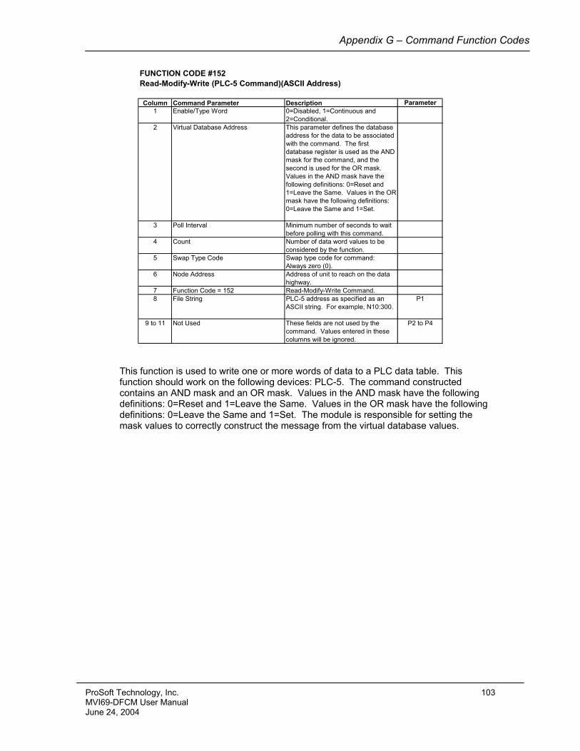
Appendix G – Command Function Codes
FUNCTION CODE #152Read-Modify-Write (PLC-5 Command)(ASCII Address)
Column Command Parameter Description Parameter1 Enable/Type Word 0=Disabled, 1=Continuous and
2=Conditional.2 Virtual Database Address This parameter defines the database
address for the data to be associated with the command. The first database register is used as the AND mask for the command, and the second is used for the OR mask. Values in the AND mask have the following definitions: 0=Reset and 1=Leave the Same. Values in the OR mask have the following definitions: 0=Leave the Same and 1=Set.
3 Poll Interval Minimum number of seconds to wait before polling with this command.
4 Count Number of data word values to be considered by the function.
5 Swap Type Code Swap type code for command: Always zero (0).
6 Node Address Address of unit to reach on the data highway.
7 Function Code = 152 Read-Modify-Write Command.8 File String PLC-5 address as specified as an
ASCII string. For example, N10:300.P1
9 to 11 Not Used These fields are not used by the command. Values entered in these columns will be ignored.
P2 to P4
This function is used to write one or more words of data to a PLC data table. This function should work on the following devices: PLC-5. The command constructed contains an AND mask and an OR mask. Values in the AND mask have the following definitions: 0=Reset and 1=Leave the Same. Values in the OR mask have the following definitions: 0=Leave the Same and 1=Set. The module is responsible for setting the mask values to correctly construct the message from the virtual database values.
ProSoft Technology, Inc. 103 MVI69-DFCM User Manual June 24, 2004
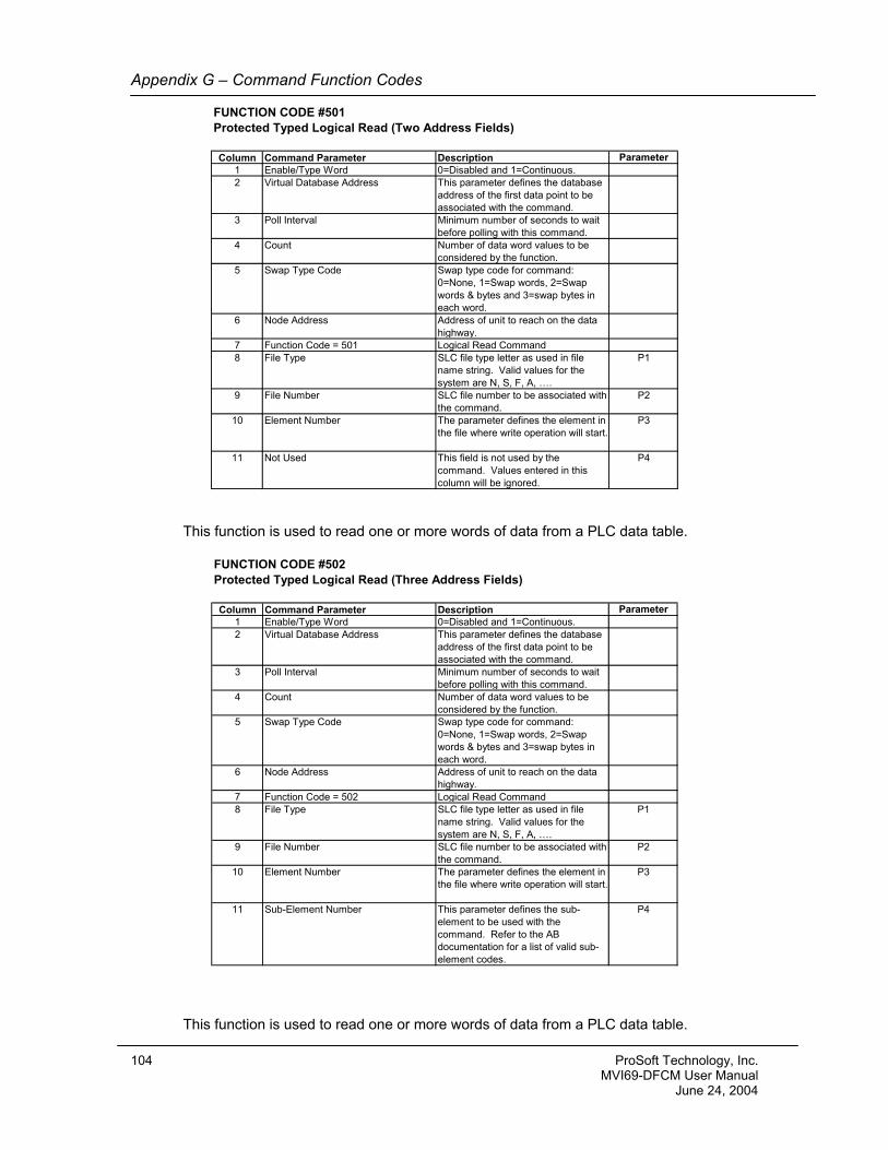
Appendix G – Command Function Codes
FUNCTION CODE #501Protected Typed Logical Read (Two Address Fields)
Column Command Parameter Description Parameter1 Enable/Type Word 0=Disabled and 1=Continuous.2 Virtual Database Address This parameter defines the database
address of the first data point to be associated with the command.
3 Poll Interval Minimum number of seconds to wait before polling with this command.
4 Count Number of data word values to be considered by the function.
5 Swap Type Code Swap type code for command: 0=None, 1=Swap words, 2=Swap words & bytes and 3=swap bytes in each word.
6 Node Address Address of unit to reach on the data highway.
7 Function Code = 501 Logical Read Command8 File Type SLC file type letter as used in file
name string. Valid values for the system are N, S, F, A, ….
P1
9 File Number SLC file number to be associated with the command.
P2
10 Element Number The parameter defines the element in the file where write operation will start.
P3
11 Not Used This field is not used by the command. Values entered in this column will be ignored.
P4
This function is used to read one or more words of data from a PLC data table.
FUNCTION CODE #502Protected Typed Logical Read (Three Address Fields)
Column Command Parameter Description Parameter1 Enable/Type Word 0=Disabled and 1=Continuous.2 Virtual Database Address This parameter defines the database
address of the first data point to be associated with the command.
3 Poll Interval Minimum number of seconds to wait before polling with this command.
4 Count Number of data word values to be considered by the function.
5 Swap Type Code Swap type code for command: 0=None, 1=Swap words, 2=Swap words & bytes and 3=swap bytes in each word.
6 Node Address Address of unit to reach on the data highway.
7 Function Code = 502 Logical Read Command8 File Type SLC file type letter as used in file
name string. Valid values for the system are N, S, F, A, ….
P1
9 File Number SLC file number to be associated with the command.
P2
10 Element Number The parameter defines the element in the file where write operation will start.
P3
11 Sub-Element Number This parameter defines the sub-element to be used with the command. Refer to the AB documentation for a list of valid sub-element codes.
P4
This function is used to read one or more words of data from a PLC data table.
104 ProSoft Technology, Inc. MVI69-DFCM User Manual June 24, 2004
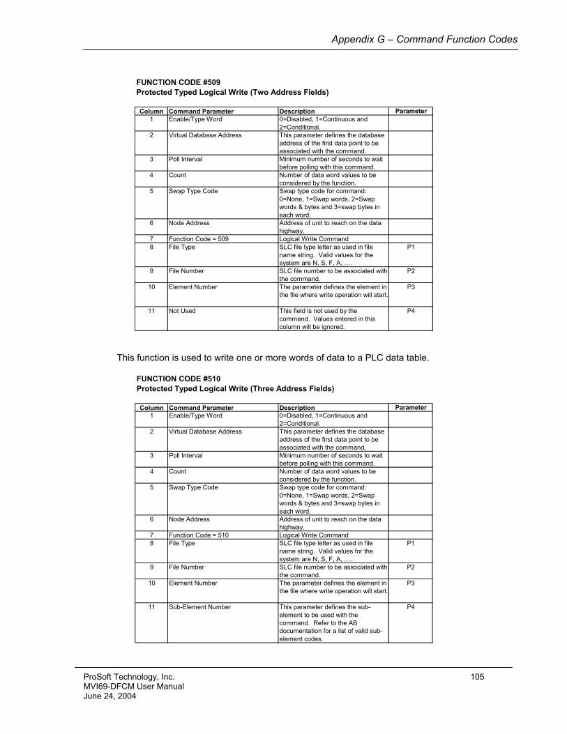
Appendix G – Command Function Codes
FUNCTION CODE #509Protected Typed Logical Write (Two Address Fields)
Column Command Parameter Description Parameter1 Enable/Type Word 0=Disabled, 1=Continuous and
2=Conditional.2 Virtual Database Address This parameter defines the database
address of the first data point to be associated with the command.
3 Poll Interval Minimum number of seconds to wait before polling with this command.
4 Count Number of data word values to be considered by the function.
5 Swap Type Code Swap type code for command: 0=None, 1=Swap words, 2=Swap words & bytes and 3=swap bytes in each word.
6 Node Address Address of unit to reach on the data highway.
7 Function Code = 509 Logical Write Command8 File Type SLC file type letter as used in file
name string. Valid values for the system are N, S, F, A, ….
P1
9 File Number SLC file number to be associated with the command.
P2
10 Element Number The parameter defines the element in the file where write operation will start.
P3
11 Not Used This field is not used by the command. Values entered in this column will be ignored.
P4
This function is used to write one or more words of data to a PLC data table.
FUNCTION CODE #510Protected Typed Logical Write (Three Address Fields)
Column Command Parameter Description Parameter1 Enable/Type Word 0=Disabled, 1=Continuous and
2=Conditional.2 Virtual Database Address This parameter defines the database
address of the first data point to be associated with the command.
3 Poll Interval Minimum number of seconds to wait before polling with this command.
4 Count Number of data word values to be considered by the function.
5 Swap Type Code Swap type code for command: 0=None, 1=Swap words, 2=Swap words & bytes and 3=swap bytes in each word.
6 Node Address Address of unit to reach on the data highway.
7 Function Code = 510 Logical Write Command8 File Type SLC file type letter as used in file
name string. Valid values for the system are N, S, F, A, ….
P1
9 File Number SLC file number to be associated with the command.
P2
10 Element Number The parameter defines the element in the file where write operation will start.
P3
11 Sub-Element Number This parameter defines the sub-element to be used with the command. Refer to the AB documentation for a list of valid sub-element codes.
P4
ProSoft Technology, Inc. 105 MVI69-DFCM User Manual June 24, 2004
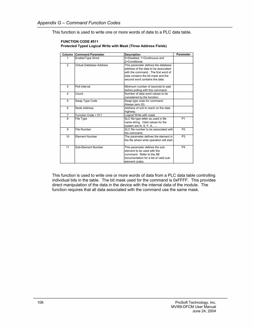
Appendix G – Command Function Codes
This function is used to write one or more words of data to a PLC data table.
FUNCTION CODE #511Protected Typed Logical Write with Mask (Three Address Fields)
Column Command Parameter Description Parameter1 Enable/Type Word 0=Disabled, 1=Continuous and
2=Conditional.2 Virtual Database Address This parameter defines the database
address of the data to be associated with the command. The first word of data contains the bit mask and the second word contains the data.
3 Poll Interval Minimum number of seconds to wait before polling with this command.
4 Count Number of data word values to be considered by the function.
5 Swap Type Code Swap type code for command: Always zero (0).
6 Node Address Address of unit to reach on the data highway.
7 Function Code = 511 Logical Write with mask8 File Type SLC file type letter as used in file
name string. Valid values for the system are N, S, F, A, ….
P1
9 File Number SLC file number to be associated with the command.
P2
10 Element Number The parameter defines the element in the file where write operation will start.
P3
11 Sub-Element Number This parameter defines the sub-element to be used with the command. Refer to the AB documentation for a list of valid sub-element codes.
P4
This function is used to write one or more words of data from a PLC data table controlling individual bits in the table. The bit mask used for the command is 0xFFFF. This provides direct manipulation of the data in the device with the internal data of the module. The function requires that all data associated with the command use the same mask.
106 ProSoft Technology, Inc. MVI69-DFCM User Manual June 24, 2004
Support, Service & Warranty
Support, Service, and Warranty Technical Support ProSoft Technology survives on its ability to provide meaningful support to its customers. Should any questions or problems arise, please feel free to contact us at:
Factory/Technical Support ProSoft Technology, Inc.
1675 Chester Avenue, 4th Floor Bakersfield, CA 93301
(661) 716-5100 (661) 716-5101 (fax)
E-mail address: [email protected] Web Site: http://www.prosoft-technology.com
Before calling for support, please prepare yourself for the call. In order to provide the best and quickest support possible, we will most likely ask for the following information (you may wish to fax it to us prior to calling):
1. Product Version Number 2. System hierarchy 3. Module configuration and contents of xxxx.CFG file 4. Module Operation
- Configuration/Debug status information - LED patterns
5. Information about the processor and controller tags as viewed through RSLogix 500 and LED patterns on the processor
6. Details about the serial network
An after-hours answering system (on the Bakersfield number) allows pager access to one of our qualified technical and/or application support engineers at any time to answer the questions that are important to you. Module Service and Repair The MVI69-DFCM card is an electronic product, designed and manufactured to function under somewhat adverse conditions. As with any product, through age, misapplication, or any one of many possible problems the card may require repair. When purchased from ProSoft Technology, the module has a one-year parts and labor warranty according to the limits specified in the warranty. Replacement and/or returns should be directed to the distributor from whom the product was purchased. If you need to return the card for repair, obtain an RMA number from ProSoft Technology. Please call the factory for this number and display the number prominently on the outside of the shipping carton used to return the card. General Warranty Policy ProSoft Technology, Inc. (Hereinafter referred to as ProSoft) warrants that the Product shall conform to and perform in accordance with published technical specifications and the accompanying written materials, and shall be free of defects in materials and workmanship, for the period of time herein indicated, such warranty period commencing upon receipt of the Product.
ProSoft Technology, Inc. 107 MVI69-DFCM User Manual June 24, 2004

Support, Service & Warranty
This warranty is limited to the repair and/or replacement, at ProSoft's election, of defective or non-conforming Product, and ProSoft shall not be responsible for the failure of the Product to perform specified functions, or any other non-conformance caused by or attributable to: (a) any misapplication or misuse of the Product; (b) failure of Customer to adhere to any of ProSoft's specifications or instructions; (c) neglect of, abuse of, or accident to, the Product; or (d) any associated or complementary equipment or software not furnished by ProSoft. Limited warranty service may be obtained by delivering the Product to ProSoft and providing proof of purchase or receipt date. Customer agrees to insure the Product or assume the risk of loss or damage in transit, to prepay shipping charges to ProSoft, and to use the original shipping container or equivalent. Contact ProSoft Customer Service for further information. Limitation of Liability EXCEPT AS EXPRESSLY PROVIDED HEREIN, PROSOFT MAKES NO WARRANT OF ANY KIND, EXPRESSED OR IMPLIED, WITH RESPECT TO ANY EQUIPMENT, PARTS OR SERVICES PROVIDED PURSUANT TO THIS AGREEMENT, INCLUDING BUT NOT LIMITED TO THE IMPLIED WARRANTIES OF MERCHANT ABILITY AND FITNESS FOR A PARTICULAR PURPOSE. NEITHER PROSOFT OR ITS DEALER SHALL BE LIABLE FOR ANY OTHER DAMAGES, INCLUDING BUT NOT LIMITED TO DIRECT, INDIRECT, INCIDENTAL, SPECIAL OR CONSEQUENTIAL DAMAGES, WHETHER IN AN ACTION IN CONTRACT OR TORT (INCLUDING NEGLIGENCE AND STRICT LIABILITY), SUCH AS, BUT NOT LIMITED TO, LOSS OF ANTICIPATED PROFITS OR BENEFITS RESULTING FROM, OR ARISING OUT OF, OR IN CONNECTION WITH THE USE OR FURNISHING OF EQUIPMENT, PARTS OR SERVICES HEREUNDER OR THE PERFORMANCE, USE OR INABILITY TO USE THE SAME, EVEN IF PROSOFT OR ITS DEALER'S TOTAL LIABILITY EXCEED THE PRICE PAID FOR THE PRODUCT. Where directed by State Law, some of the above exclusions or limitations may not be applicable in some states. This warranty provides specific legal rights; other rights that vary from state to state may also exist. This warranty shall not be applicable to the extent that any provisions of this warranty are prohibited by any Federal, State or Municipal Law that cannot be preempted. Hardware Product Warranty Details Warranty Period: ProSoft warranties hardware product for a period of one (1) year. Warranty Procedure: Upon return of the hardware Product ProSoft will, at its option, repair or replace Product at no additional charge, freight prepaid, except as set forth below. Repair parts and replacement Product will be furnished on an exchange basis and will be either reconditioned or new. All replaced Product and parts become the property of ProSoft. If ProSoft determines that the Product is not under warranty, it will, at the Customer's option, repair the Product using current ProSoft standard rates for parts and labor, and return the Product freight collect.
108 ProSoft Technology, Inc. MVI69-DFCM User Manual June 24, 2004
Support, Service & Warranty
Return Policy We strive to provide the best products available. Your satisfaction is important to us. All returned products must be marked with a Returned Merchandise Authorization number. Units under warranty returned because of defects must be pre-approved by the Technical Support Department to obtain an RMA #. To return a unit under warranty: Defective Units: Contact the Technical Support Department for approval on all defective returns. Phone 661-716-5100 or email [email protected]. Defective units under warranty will be immediately replaced. Return for Credit Only: Contact your original purchasing distributor for an RMA #. Returns for order error, quantity error, project change, etc., are subject to restocking charges: 10% restocking fee if factory seal has not been broken 20% restocking fee if factory seal has been broken All cables and accessories must be intact or additional charges may apply. If you do not know who your distributor is, contact our Returns Department at 661-716-5100 or by email at [email protected]. All invoicing will be billed through the original purchasing distributor. For warranty claims on a defective unit, an invoice for the replacement will be generated and credit will be issued when the defective unit is returned and a manufacturer defect is found. If the defect is not manufacturer related, credit will not be issued and payment for the replacement is due. To return a non-warranty unit for repair, contact the Technical Support Department. Product Warranty Information ProSoft Technology, Inc. products, excepting RadioLinx products, are warranted to be free from any defect in material and workmanship for a period of one (1) year from the date of shipment. RadioLinx radios are warranted to be free from any defect in material and workmanship for a period of three (3) years from the date of shipment. Radio accessory items (antennas, cables, etc.) are non-refundable items and cannot be returned for credit.
ProSoft Technology, Inc. 109 MVI69-DFCM User Manual June 24, 2004
Support, Service & Warranty
110 ProSoft Technology, Inc. MVI69-DFCM User Manual June 24, 2004
- - - - - - - - - - - - - - - - END OF MANUAL - - - - - - - - - - - - - -
- - -