mv breaking techniques - studiecd.dkstudiecd.dk/cahiers_techniques/mv_breaking_techniques.pdf · mv...
TRANSCRIPT

..........................................................................Collection Technique
Cahier technique no. 193
MV breaking techniques
S. Théoleyre

"Cahiers Techniques" is a collection of documents intended for engineersand technicians, people in the industry who are looking for more in-depthinformation in order to complement that given in product catalogues.
Furthermore, these "Cahiers Techniques" are often considered as helpful"tools" for training courses.They provide knowledge on new technical and technological developmentsin the electrotechnical field and electronics. They also provide betterunderstanding of various phenomena observed in electrical installations,systems and equipments.Each "Cahier Technique" provides an in-depth study of a precise subject inthe fields of electrical networks, protection devices, monitoring and controland industrial automation systems.
The latest publications can be downloaded from the Schneider Electricinternet web site.Code: http://www.schneider-electric.comSection: Experts' place
Please contact your Schneider Electric representative if you want either a"Cahier Technique" or the list of available titles.
The "Cahiers Techniques" collection is part of the Schneider Electric’s"Collection technique".
ForewordThe author disclaims all responsibility subsequent to incorrect use ofinformation or diagrams reproduced in this document, and cannot be heldresponsible for any errors or oversights, or for the consequences of usinginformation and diagrams contained in this document.
Reproduction of all or part of a "Cahier Technique" is authorised with theprior consent of the Scientific and Technical Division. The statement"Extracted from Schneider Electric "Cahier Technique" no. ....." (pleasespecify) is compulsory.

Cahier Technique Schneider Electric no. 193 / p.1
no. 193MV breaking techniques
ECT 193 first issue, June 1999
Serge THEOLEYRE
Dr. Theoleyre joined Schneider Electric in 1984 after having obtaineda Doctorate in Engineering from the “Ecole Nationale Supérieured’Ingénieurs Electriciens” in Grenoble in 1983. Initially he took chargeof research and development and then marketing for the PowerCapacitor activity.Since 1995, he has been responsible for Schneider Electric’s actionsin the fields of standardization and technical communication withinthe Transmission and Distribution Business sector (HV/MV).

Cahier Technique Schneider Electric no. 193 / p.2
Lexicon
Breaking Capacity:A presumed current value that a switchingdevice must be capable of breaking under therecommended conditions of use and behavior.
Earthing fault:Fault due to the direct or indirect contact of aconductor with the earth or the reduction of itsinsulation resistance to earth below a specifiedvalue.
Fault:Accidental modification affecting normaloperation.
Ir:Rated current corresponding to the rms. value ofthe current that the device must be capable ofwithstanding indefinitely under the recommendedconditions of use and operation.
Isc:Short-circuit current.
Overvoltage:Any voltage between a phase conductor and theearth or two neutral phase conductors where thepeak value exceeds the highest voltageacceptable for the equipment.
Overvoltage factor:Ratio between the overvoltages’ peak value andthe peak value of the maximum voltageacceptable by the device.
Rated value:Value generally set by the manufacturer forgiven operating conditions for a component, amechanism or piece of equipment.
Re-ignition:Resumption of current between the contacts of amechanical switching device during a breakingoperation, within a quarter cycle after passing to0 current.
Re-striking:Resumption of current between the contacts of amechanical switching device during a breakingoperation, after a quarter cycle after passing to 0current.
Short-circuit:An accidental or intentional connection through aresistance or relatively low impedance, of two ormore points on a circuit normally existing atdifferent voltages.
Switching device:Device intended to establish or interrupt currentin an electrical circuit.
Switchgear:General term applicable to switching devices andtheir use in combination with control,measurement, protection, and command deviceswith which they are associated.
Time constant for de-ionization:Time at the end of which arc resistance will havedoubled assuming that its rate of variationremains constant.
Transient recovery voltage:Recovery voltage between the contacts of aswitching device during the time where itpresents an noticeable transient character.
Ur:Rated voltage corresponding to the rms. value ofthe voltage that the device must be capable ofwithstanding indefinitely under the recommendedconditions of use and operation.

Cahier Technique Schneider Electric no. 193 / p.3
MV breaking techniques
Contents
1 Introduction p. 4
2 Breaking load and fault currents 2.1 Breaking principle p. 6
2.2 Breaking load currents p. 9
2.3 Breaking fault currents p. 13
3 Breaking techniques 3.1 Breaking medium p. 17
3.2 Breaking in air p. 18
3.3 Breaking in oil p. 19
3.4 Breaking under vacuum p. 21
3.5 Breaking in SF6 p. 24
3.6 Comparison of the various techniques p. 29
3.7 What possibilities for other techniques? p. 30
4 Conclusion p. 31
Bibliography p. 32
The ability to break current in an electrical circuit is essential in order toguarantee the safety of people and property in the case of faults, as well asto control the distribution and use of electrical energy.
The aim of this Cahier Technique is to detail the advantages,disadvantages and applicational fields of past and present Medium Voltagebreaking techniques.
Having defined the currents to be broken and discussed breaking on atheoretical level, the author goes on to present breaking in air, oil, and inSF6, finishing with two comparative tables.
To date, breaking using electrical arcing remains the only viable solution,whether in SF6 or under vacuum; it requires expertise that thisCahier Technique invites you to share.

Cahier Technique Schneider Electric no. 193 / p.4
1 Introduction
Electrical energy is transmitted from thegenerating power station to consumer points viaan electrical network (shown in figure 1 ).It is essential to be able to interrupt the current atany point in the network in order to operate ormaintain the network or to protect it when a faultoccurs. It is also necessary to be able to restorecurrent in various normal or fault situations.In order to choose the devices intended toaccomplish this task, information on the currentto break and the field of application is crucial(see fig. 2 ). It can fall into one of threecategories:
c Load current, which is normally smaller thanthe rated current Ir. The rated current, Ir is therms. value of current that the equipment must becapable of withstanding indefinitely under therecommended conditions of use and operation.c Overload current, when the current exceeds itsrated value.c Short-circuit current, when there is a fault onthe network. Its value depends on the generator,the type of fault and the impedances upstream ofthe circuit.
Furthermore, when opening, closing or incontinuous service the device is subjected toseveral stresses:c dielectrical (voltage),c thermal (normal and fault currents),
c electrodynamic (fault current),c mechanical.
The most important stresses are those whichoccur during transient operation and breaking,which are accompanied by electrical arcingphenomena. Arcing behavior is difficult to predictdespite current modeling techniques.
Experience, know-how and experimentation stillplay a large part in designing breaking devices.They are called “electromechanical” devices,since at present static breaking in medium andhigh voltage is not technically and economicallyviable.
Of all of these breaking devices, circuit breakersare the most interesting since they are capableof making, withstanding, and breaking currentsunder normal and abnormal conditions (short-circuit). This Cahier Technique will mainlydiscuss breaking alternating current using circuitbreakers.
The voltage range considered is that of MediumVoltage (1 kV - 52 kV), since it is in this voltagerange that the greatest number of breakingtechniques exist. The first part of the documentwill deal with phenomena occurring duringbreaking and closing. The second part presentsthe four most wide-spread types of breakingtechniques currently used i.e. breaking in air, oil,vacuum and SF6.
Powerstation
EHVtransmission network
800 kV - 300 kV
HVsubtransmission network
300 kV - 52 kV
MVdistribution network
52 kV - 1 kV
LV distribution network
1 kV - 220 V
EHV/HVtransformersubstations
HV/MVtransformersubstations
MV/LVtransformersubstations
MVconsumers
LVconsumers
HVconsumers
Fig. 1 : diagram of an electrical network.

Cahier Technique Schneider Electric no. 193 / p.5
c IEC definition Opening Closing Isolating
c Function
Disconnector c Mechanical connection device yes no no yes no yes v yeswhich in an open positionguarantees asatisfactory isolatingdistance under specific conditions.c Intended to guarantee safeisolation of a circuit, it is oftenassociated with an earthing switch.
Earthing c Specially designed switch for yes no no yes no yes v noswitch connecting phase conductors to the earth.
c Intended for safety in case of workon the circuits, it relays the de-energizedactive conductors to the earth.
Switch c Mechanical connection device capable yes yes no yes yes yes yes vof establishing, sustaining and breakingcurrents under normal circuit conditionseventually including overload currents inservice.c Intended to control circuits (openingand closing), it is often intended toperform the insulating function.In public and private MV distributionnetworks it is frequently associatedwith fuses.
Contactor c Mechanical connection device with yes yes no yes yes yes noa single rest position, controlled otherthan by hand, capable of establishing,sustaining and breaking currents undernormal circuit conditions, includingovervoltage conditions in service.c Intended to function very frequently,it is mainly used for motor control.
Circuit c Mechanical connection device capable yes yes yes yes yes yes nobreaker of establishing, sustaining and breaking
currents under normal circuit conditionsand under specific abnormal circuitconditions such as during a short-circuit.c General purpose connection device.Apart from controlling the circuits itguarantees their protection againstelectrical faults. It is replacing contactorsin the control of large MV motors.
Fig. 2 : various switching devices, their functions and their applications
= at no load = under load = short-circuit v = depending on the case

Cahier Technique Schneider Electric no. 193 / p.6
2 Breaking load and fault currents
2.1 Breaking principle
An ideal breaking device would be a devicecapable of breaking current instantaneously.However, no mechanical device is capable ofbreaking current without the help of electricalarcing. This phenomenon limits overvoltages anddissipates the electromagnetic energy of theelectrical circuit, but it delays complete breakingof the current.
The ideal switch
Theoretically speaking, being able to breakcurrent instantaneously, it involves being able topass directly from the state of conductor to thestate of insulator. The resistance of the “ideal”switch must therefore pass immediately fromzero to infinity, (see fig. 3 ).
This device must be capable of:
c absorbing the electromagnetic energyaccumulated in the circuit before breaking, i.e.12
Li2 in case of a short-circuit due to the
reactive nature of the networks;
Fig. 3 : breaking by an ideal switch.
Break
i
R
t
t
R L
e Load
c withstanding the overvoltage (Ldi/dt) appearingacross the terminals of the device and whichwould have an infinite value if passing frominsulator to conductor occurred in an infinitelysmall period of time. This would inevitably lead todielectric breakdown.
Assuming that these problems have beeneliminated and that perfect synchronization hasbeen achieved between the natural passing ofthe current to 0 and the device’s insulator-conductor transition, there still remains anotherdifficult aspect to take into consideration, that oftransient recovery voltage (TRV).
In fact, just after the current has beeninterrupted, the recovery voltage across theswitch’s terminals joins the network voltagewhich is at its maximum at this moment forreactive circuits. This occurs without an abruptdiscontinuity due to the parasite capacitances ofthe network. An unsteady state is set up whilstthe voltage comes back in line with that of thenetwork. This voltage, called transient recoveryvoltage (TRV), depends on networkcharacteristics and the rate of increase (dv/dt) ofthis voltage can be considerable (several kV /microsecond). To put it simply this means that toavoid breaking failure, the ideal switch must becapable of withstanding several kV less than onemicrosecond after the transition from conductor-insulator.
Breaking using electrical arcing
Two reasons explain the existence of electricalarcing:
c It is practically impossible to separate thecontacts exactly at the natural 0 current pointdue to the uncertainty in the measurement-order:for an rms. value of 10 kA, the instantaneouscurrent 1 ms before 0 is still at 3,000 A. Theinstantaneous overvoltage Ldi/dt which wouldappear across the terminals of the device if itimmediately became insulating would be infiniteand lead to the immediate breakdown across theinter-contact gap which is still small.
c Separation of the contacts must beaccomplished at sufficient speed for thedielectric strength between the contacts toremain greater than the transient recoveryvoltage. This requires mechanical energy closeto infinity, that no device can provide in practice.

Cahier Technique Schneider Electric no. 193 / p.7
The electrical arcing breaking process takesplace in three phases :v the sustained arc phase,v the arc extinction phase,v the post-arcing phase.
c Arc propagation phase
Before reaching zero current the two contactsseparate causing dielectric breakdown of theinter-contact medium. The arc which appears ismade up of a plasma column composed of ionsand electrons from the inter-contact medium ormetal vapor given off by the electrodes(see fig. 4 ). This column remains conductive aslong as its temperature is maintained at asufficiently high level. The arc is thereby“sustained” by the energy that it dissipates by theJoule effect.The voltage which appears between the twocontacts due to the arc’s resistance and thesurface voltage drops (cathodic and anodicvoltage) is called the arcing voltage (Ua).Its value, which depends on the nature of thearc, is influenced by the intensity of the currentand by the heat exchange with the medium(walls, materials, etc.). This heat exchangewhich is radiative, convective and conductive ischaracteristic of the device’s cooling capacity.The arc voltage’s role is vital since the powerdissipated in the device during breaking stronglydepends on it.
Fig. 4 : electrical arcing in a gaseous medium.
W U idt at
t
0
arc= ∫ where t0 is the moment of arc
initiation and tarc is the moment of breaking.In medium voltage and high voltage, it alwaysremains well below network voltages and doesnot therefore have a limiting effect, except inparticular cases discussed further on. Breakingis therefore near the “natural” zero of thealternating current.
c Arc extinction phase
Interrupting of the current corresponding to arcextinction is accomplished at zero current oncondition that the medium quickly becomesinsulating again. For this to occur, the channel ofionized molecules must be broken. Theextinction process is accomplished in thefollowing manner: near zero current, resistanceto the arc increases according to a curve whichmainly depends on the de-ionization timeconstant in the inter-contact medium (see fig. 5 ).
e
e
e
e
e
Nion +
Anode
Cathode
ion +
ion –
Post arccurrent
R
t
t
Rr
ur
ir
ie
ue
Re
i, u
a
b
Fig. 5 : change in arc resistance [a] current andvoltage [b] during the extinction phase in case ofsuccessful breaking (r) or thermal failure (e).

Cahier Technique Schneider Electric no. 193 / p.8
At zero current, this resistance has a value whichis not infinite and a post-arcing current onceagain crosses the device due to the transientrecovery voltage which appears across theterminals.
If the power dissipated by the Joule effect exceedsthe characteristic cooling capacity of the device,the medium no longer cools down: thermalrunaway followed by another dielectric breakdowntakes place: resulting in thermal failure.
If on the other hand the increase in voltage doesnot exceed a certain critical value, the arc’sresistance can increase sufficiently quickly sothat the power dissipated into the mediumremains less than the cooling capacity of thedevice thereby avoiding thermal runaway.
c Post-arcing phase
In order for breaking to be successful, it is alsonecessary for the rate of dielectric recovery to bemuch quicker than that of the TRV (see fig. 6 )otherwise dielectric breakdown occurs.At the moment when dielectric failure occurs, themedium once again becomes conductive,generating transient phenomena which will belooked at in more detail further on.These post-breaking dielectric failures are called:v re-ignition if it takes place within the quarter ofa period following the zero current,v re-striking if it takes place afterwards.
c TRV in the standards
Even though the rate of increase of TRV has afundamental impact of on the breaking capacitiesof devices, this value cannot be preciselydetermined for all network configurations.Standard IEC 60056 defines a TRV range foreach rated voltage corresponding to therequirements normally encountered (see fig. 7 ).The breaking capacity of a circuit breaker istherefore defined as: the highest current that itcan break at its rated voltage with thecorresponding rated TRV.
Fig. 6 : dielectric recovery curves:successful breaking [a] or dielectric failure [b].
Fig. 7 : rated transient recovery voltage in the case of a short-circuit across the terminals of a circuit breaker(§ 4.102 IEC standard 60056).
U
U
t
Recovery voltage
t
0
0
a
b
Recovery voltage with restriking
Dielectric regeneration curves
Recovery voltage if no restriking
UTRV
UC
tt3
Rated voltage 7.2 12 17.5 24 36 52(Ur in kV)
Peak TRV value 12.3 20.6 30 41 62 89(Uc in kV)
Time t3 (in µs) 52 60 72 88 108 132
Rate of increase 0.24 0.34 0.42 0.47 0.57 0.68(Uc / t3)
A circuit breaker must be capable of breaking allcurrents less than its breaking capacity for allTRVs whose value is less than the rated TRVvalue.

Cahier Technique Schneider Electric no. 193 / p.9
2.2 Breaking load currents
Under normal operation, in MV, circuit breakingoccurs:
c with a load current from a few to a few hundredamperes, a low value relative to the short-circuitcurrent (from 10 to 50 kA);
c with a power factor greater than or equal to0.8. The phase shift between the electrical circuitvoltage and the current is small and theminimum voltage occurs around the current’sminimum (highly resistant circuit).
The voltage across the terminals of the breakingdevice is established while network voltage ispractically without any transient phenomena(see fig. 8 ).Under such conditions, breaking generallyoccurs without any problems since the device isdimensioned for high currents in quadrature withthe voltage.
Breaking inductive currentsc Current choppingBreaking inductive currents can give rise toovervoltages caused by early breaking of thecurrent, otherwise known as “current chopping”phenomena.For low inductive currents (from a few amperesto a several dozens of amperes), the coolingcapacity of the devices dimensioned for theshort-circuit current is much higher in relation tothe energy dissipated in the arc. This leads to
U (between contacts)
a100 V
i
t
t
Separationof contacts
Effective currentbreaking
Arc period
Fig. 8 : there are very few transient phenomena duringthe breaking of a resistive load current.
arc instability and an oscillating phenomenaoccurs which is “seen” by the breaking deviceand the inductances (see fig. 9 and fig. 10 ).During this high frequency oscillation (of around1 MHz) passing to zero current is possible andthe circuit breaker can interrupt the currentbefore it passes to its natural zero at theindustrial frequency (50 Hz).
Ua U
L1
L
L2C1 C2U1 U2
L1 , C1 = upstream inductance and capacity(supply source),L2 , C2 = downstream inductance and capacity(transformer primary),
L = connection inductance downstream of circuitbreaker D (busbars or cables).
i
t
i
t
iiia
Naturalcurrent zero
i = current in the circuit breaker,ii = current value leading to instability,ia = chopped current value.
Fig. 9 : diagram of the circuit on breaking a lowinductive current.
Fig. 10 : high frequency oscillating phenomena or“current chopping” on breaking an inductive current.

Cahier Technique Schneider Electric no. 193 / p.10
This phenomenon, called “current chopping”, isaccompanied by a transient overvoltage mainlydue to the oscillatory state which is set up on theload side (see fig. 11 ).The maximum value of the overvoltage (UCmax)on the load side is given by the followingequation:
U u
Cmax2
a2= +
ηm aL iC
22
2
in which:ua = chopping voltage,ia = chopping current,ηm = magnetic efficiency.
Current to be interrupted
t
t
t
Load voltage
Source voltage
Voltage across the circuit-breaker terminals Source voltage
Fig. 11 : voltage and current curves at the time ofbreaking low inductive currents.
On the supply side, the voltage value is equal tothe value of the chopping voltage tendingtowards the network voltage, Un with anoscillating state depending on C1 and L1. Thevoltage value between the contacts of the circuitbreaker is equal to the difference between thesetwo voltages.These equations clearly show the influence ofthe network’s characteristics, bearing in mindthat the chopping current depends strongly onC1 and on the concerned device.
c Re-ignition
Another phenomena can lead to highovervoltages. It is re-ignition during opening.Generally speaking, re-ignition is inevitable forshort arcing periods since the distance betweencontacts is not sufficient to withstand the voltagewhich appears across the terminals of thedevice. This is the case each time an arc appearsjust before the current passes to natural zero.The voltage on the load side rejoins the voltageon the supply side with an unsteady stateoscillating at high frequency (around 1 MHz).The peak value of the oscillation, determined bythe load voltage of the downstream parasitecapacitances is therefore twice the precedingvalue.If the circuit breaker is capable of breaking highfrequency currents, it will manage to break thecurrent the first time it passes to zero a fewmicroseconds after re-ignition. Re-ignition is verylikely to reoccur due to the increase in theamplitude of oscillation and the phenomena isrepeated causing an escalation in voltage whichcan be dangerous for the load(see Cahier Technique no. 143).It should be noted that the same phenomenaappears during device closure: it causes pre-striking when the contacts are broughtsufficiently close together. As in cases ofsuccessive re-ignition, the stored energyincreases at each breaking attempt but thevoltage increase is limited by the bringingtogether of the contacts.
c Field of application
In Medium Voltage this involves the magnetizingcurrents of transformers under no load or lowload, motors and shunt inductances.
v Transformers under no load or low load
Transformers can be operated under low loadconditions (e.g. at night) for networkmanagement requirements. The currentscorresponding to their magnetizing currents varyfrom a few amperes to several dozens ofamperes and their chopping factor can be veryhigh. However, even if the current is chopped atits peak value, the possible overvoltage factorsare generally low taking into account thecapacitances and the inductances involved.

Cahier Technique Schneider Electric no. 193 / p.11
In overhead distribution, the risk related to theappearance of overvoltage current is even lowersince it is limited by lightning arrestors.Furthermore, standards relating to transformersdefine impulse wave tests which confirm theircapacity to withstand operational overvoltages.
v Shunt inductances
These inductances are used to compensate forthe reactive component of the lines or to avoidincreases in voltage on very long lines with lowloads. They are most often used in HV but canalso be used in MV.Breaking overvoltages generally remain belowan overvoltage factor of 2.5 due to theimpedances involved. If there is a risk that thebreaking overvoltage will exceed this limit,lightning arrestors and breaking resistors areconnected in parallel with the circuit breaker.
v Motors
Stator and rotor windings of motors are so thatthe current absorbed under no load conditions bythese motors as well as the start-up currents arebasically inductive. Given the great number ofswitching operations, overvoltages occur veryoften and can become critical because of theprogressive deterioration in the insulation thatthey engender, in particular if opening occursduring the start-up phases.As a general rule, circuit breakers must bechosen that do not re-strike or that have a lowprobability of re-striking. Otherwise, R-C systemscan also be placed across the motor’s terminalsin order to deviate high frequency transientcurrents or ZnO type voltage limiting systems.
c Breaking inductive currents and the standards.
International standards do not exist regarding thebreaking of inductive currents, however IECtechnical report 61233 stipulates tests for circuitbreakers used to supply the motors and shuntinductances.
v Motors
For circuit breakers with rated voltages between1 kV and 17.5 kV, a standardized circuitsimulating a blocked motor is specified forlaboratory tests.
v Shunt inductances
They are not very wide-spread in MV,nevertheless, they are sometimes used in 36 kV.The tests carried out in a laboratory are solelydefined for three phase circuits with a ratedvoltage greater than 12 kV.
Breaking capacitive currentsBreaking capacitive currents can cause toovervoltages due to re-striking during the voltagerecovery phase.
c In theory, capacitive currents can be brokenwithout any difficulty. In fact, when the device
interrupts the current, the voltage across theterminals of the generator is at its maximumsince the current and the voltage are out ofphase by π/2; since the capacitor remainscharged at this value after current breaking, thevoltage across the terminals of the switch,initially at 0, slowly increases without TRV andwith a derivative in relation to time (dv/dt) equalto zero at the origin.
c On the other hand re-striking problems aredifficult. In fact, after a 1/2-period, the networkvoltage is reversed and the voltage across theterminals of the switch reaches twice the peakvalue. The risk of re-striking between thecontacts is therefore increased and this isproportional to the slowness of opening.If there is re-striking at peak voltage, thecapacitor is discharged in the circuit’s inductancecreating an oscillating current with a peakvoltage of 3 (see fig. 12 ). If breaking is effectiveat the following zero current, the capacitorremains charged at a voltage of 3.
I Ua
Ub
Peakvoltage
-3 peak voltage
Currentoscillations
Voltageoscillations
Current afterrestriking
Ub afterrestriking
I
Ua Ub
u L
e C C
Fig. 12 : diagram of a circuit with a capacitive load:during breaking if the circuit breaker does not openquickly enough, successive re-striking can causedangerous overvoltages for the load.

Cahier Technique Schneider Electric no. 193 / p.12
When voltage “e” is once again reversed, thepeak voltage across the terminals of the switchbecomes equal to 5. The overvoltage cantherefore lead to re-striking again. Thephenomena can continue with a voltage acrossthe terminals of the switch capable of reachingvalues of 7, 9, etc.For all re-striking occurring 1/4 of the periodfollowing zero current, an “escalation of voltage”can be observed which can lead to unacceptablepeak values for loads.
On the other hand re-striking, which occursdepending on the breaking device’s dimensions,is tolerable: the oscillating voltage across theterminals of the capacitor remains at an absolutevalue less than the peak value of the generator’svoltage, which does not represent any particulardanger for the devices.As a reminder, capacitor overvoltage testing isperformed at 2.25 times the rated voltage value.Dielectric recovery of the inter-contact mediummust therefore be sufficiently quick for no re-striking to occur after the quarter period.
c Making capacitive currents and pre-striking
When closing the control device supplyingcapacitive loads, phenomena specific tocapacitive circuits are produced.Thus, energizing a capacitor bank causes a highovercurrent at high frequency (see fig. 13 ) forwhich the peak magnitude is given by theequation:
IpC
L
U 2
3 L=
+0
whereL0 = upstream network inductanceL = capacitor bank link inductances, generallylow in relation to L0.
In the case of multi-stage banks, the phenomenais even more accentuated by the presence of theenergy stored in the already energizedcapacitors: the transient currents can reachseveral hundreds of times the rated current withfrequencies of several kHz due to the low valuesof link inductance between stages of the banks.
During pre-striking at the breaking devicecontacts (ignition of a conductive arc before thecontacts join) these high transient currents causeearly erosion of the breaking device contacts andeventually weld them. Limiting inductances(impulse impedances) are series connected withthe bank in order to limit these phenomena.
Fig. 13 : shapes of voltage and current (pre-strikeovervoltage) during the coupling of a single stagecapacitor to the network.
Network voltage
Capacitor voltage
Capacitor current
SA (upstreamovervoltage)
SB (downstreamovervoltage)
Ip (peak closing current)
fe (oscillatingfrequency)
L
e C
L0
The aforementioned equation becomes:
IpC
U 2
3 L
nn 1
=+
wheren = number of capacitor bank stages with avalue of C.L = limiting inductances (impulse impedances),higher in relation to L0.Note that devices adapted to this applicationexist and must be specified.

Cahier Technique Schneider Electric no. 193 / p.13
c Fields of application
Capacitive currents mainly have two origins:cables and lines, and capacitor banks.
v Cables and linesThis involves load currents in no-load cables andlong overhead lines (compensated or not). In anumber of European countries (especiallycountries in Southern Europe, France, Italy,Spain, etc.), MV overhead networks are long andtherefore particularly sensitive to atmosphericovervoltages meaning a high amount of trippingoccurs on these lines… therefore a lot of re-striking.
v Capacitor banksCapacitor banks are series connected to thenetworks and are used to compensate for thelines’ reactive energy (transmission network) andloads (MV/LV). They enable the transmittedactive power to be increased and line losses tobe reduced. They can be:- used alone in the case of low compensationand a stable load,- staggered (multiple or divided). This type ofbank is widely used by major industries (highinstalled power) and by utilities companies. It isassociated with an automatic control and thenumber of operations can be high (severaloperations per day): devices capable ofwithstanding a suitable number of operationsshould be specified.
c Breaking capacitive currents and thestandards
The current IEC standard 60056 (4th edition,1987) gives values, for all voltages, of the ratedbreaking capacity of circuit breakers used to
protect cables which may have no load. Itsapplication is not mandatory and it is consideredinappropriate for voltages less than 24 kV.Regarding the rated breaking capacity of linesunder no load, the specification is limited todevices with a rated voltage of 72 kV.No value has been specified for capacitor banks.IEC 60056 also specifies switching tests(see fig. 14 ) for protection and control devicesunder capacitive current conditions for lines andcables under no load and for single stagecapacitor banks but does not specify anything forlong lines nor for banks of filters.Standards for capacitive current applications aretending to develop towards the definition ofdevices with a low probability of re-strikingtogether with a broader specification of valuesand a higher number of switching operations inorder to guarantee their suitability to theapplication.
2.3 Breaking fault currents
In the case of a short circuit, the phase shiftbetween the current and the voltage is alwaysvery large (0.07 i cosϕ i 0.15), since networks arebasically inductive. When the current passes to 0,network voltage is at, or almost at, its maximum.
In MV, short-circuit current reaches values of afew tens of thousands of amperes.Consequently, breaking takes place withoutcurrent chopping since the arc is very stable. Asfor load currents, arcing can be broken down intothree phases:
c a sustained arc phase till passing through zerocurrent,
c an extinction phase,
c a recovery phase.
Short-circuit currentsc The various fault types(see Cahier Technique no. 158)
Among the various types of faults (three-phase,two phase, single phase and earthing), the mostfrequent fault is the single phase earthing fault(80% of short-circuits). It is generally caused byphase-earth insulation faults following over-voltages of atmospheric origin, due to broken orfaulty insulation or due to civil engineering works.
Testing Isc of the supply Testingduty circuit as a function current
of circuit breaker’s (% of ratedbreaking capacity Icapa)(Isc / Breakingcapacity) x100
1 < 10 20 to 40
2 < 10 > 100
3 100 20 to 40
4 100 >100
Fig. 14 : testing specified by IEC 60056 for capacitivecurrents.

Cahier Technique Schneider Electric no. 193 / p.14
Three-phase short-circuits are rare (5% of thecases) but serve as a test reference since theshort-circuit current and the TRV are higher thanin single phase or two phase faults.Calculation of the fault current requiresinformation on the network’s characteristics andthe neutral arrangement (insulated, directlyearthed or impedant neutral). Methods ofcalculating have been developed andstandardized (IEC 60909). Currently, calculationthrough computer simulation is fairly wide-spread,and all Schneider departments have developedsoftware which they have at their disposalenabling them to obtain very reliable results.
c Fault location
v Faults on the circuit breaker’s downstreamterminalsIt is under these conditions that short-circuitcurrent is greatest since it is only limited by theimpedances situated upstream of the device.Even though this type of fault is quite rare, it isthe one that is chosen for MV circuit breakerspecifications.
v Line faultsThis type of fault is more common than theprevious type in overhead networks, but in MV,circuit breaker arcing characteristics and circuitbreaker/ cable / line connections mean that thestresses generated are less than those causedby a short-circuit across the terminals. There aretherefore no specific tests for MV circuit breakers.In HV, this type of short-circuit requires specifictests for near-by faults since wave reflectionphenomena cause extremely damaging TRVs.
v Phase opposition type coupling (see fig. 15 )This is a special short-circuit scenario occurringwhen two unsynchronized generators arecoupled.When the two generators are out ofsynchronization, the voltage across the terminalsof the coupling circuit breaker is equal to the sumof the voltages of each generator. The currentwhich the circuit breaker must break can reachhalf the value of the current corresponding to ashort-circuit at the point of coupling. Themaximum is then attained during phaseopposition type coupling.IEC standard 60056 (§4.106) in this case requiresthat the device must be capable of breaking 25%of the fault current across the terminals at avoltage of 2.5 times the voltage to earth,covering the values encountered in practice.
c Shape of the short-circuit current plot
The intensity of the current corresponding to thetransient period during a short-circuit is the sumof two components, one symmetric or periodical(ia) and the other asymmetric or continuous (ic)(see fig. 16 ).
ia
ic
i
t
Fig. 16 : during a short-circuit the current is the sum ofthe two components, one symmetric or periodical (ia)and the other asymmetric or continuous (ic).
X1 X2
X1
Iscfeeders
X2
e1 e2
e1 e2
Isccoupling
Fig. 15 : breaking under out-of-phase conditionsduring the coupling of two generators which are outof synchronization.
with e1 = e2 = e and X1 = X2 = X
Iscfeeder eX
2eX
= + =eX
Isccoupling 2e2X
eX
= =

Cahier Technique Schneider Electric no. 193 / p.15
The symmetric component (ia) is created by thealternating source which supplies the short-circuit current.The continuous component (ic) is created by theelectromagnetic energy stored in the inductanceat the time of the short-circuit. Its value at themoment of the fault is opposite and equal to thatof the symmetric component to ensure thecontinuity of current. It decreases with a timeconstant L/R, characteristic of the network, forwhich the standardized value is 45 ms, resultingin the following equation:ia = I sin(ωt + θ)ic = - I sinθ e(-t/(L/R))
I = maximum intensity = E/Zccθ = electrical angle which characterizes the timebetween the initial moment of the fault and thebeginning of the current wave.
Two extreme cases:v The short-circuit occurs at the moment atwhich voltage (e) passes to 0. The symmetriccomponent and the continuous component are attheir maximum value. This state is called fullyasymmetrical.v The initial moment of the short-circuit coincideswith the 0 point of the current’s alternatingcomponent: the continuous component is zeroand this state is called symmetrical.
Breaking capacity
Short-circuit breaking capacity is defined as thehighest current that a device can break under itsrated voltage in a circuit in which the TRV meetsa specific specification.
A
Ur
Ur / e1.5 Ur / e
A', B, B', C, C'
A A'
B B'
C C' N'
N
N
1
1
3
32
2
The device must be capable of breaking allshort-circuit currents with a periodic componentless than its breaking capacity and a certainpercentage of the aperiodic components that donot exceed the defined value.According to the type of device, some faultcurrents less than the breaking capacity canprove difficult to break. They cause long arcingtimes with risks of non-breaking.
c Three phase breaking
Due to the phase shift of three phase currents,breaking occurs in the following manner:v The circuit breaker breaks the current in thefirst phase (phase 1 in figure 17 ) in which thecurrent passes to zero.The arrangement becomes two-phased andeverything occurs as if point N is shifted to N’.The voltage established in the first phase, acrossthe terminals of the open AA’ contact, is thatalready existing between A and N’, it thereforeequals:
UAA’ = kV = kUr / ek is the factor of the first pole. Its value variesfrom 1 to 1.5 depending on whether the neutralis directly earthed or perfectly insulated.v 1/2 a period later each of the other two phasespass to zero, the circuit breaker breaks and thenetwork becomes stable again in relation to theneutral point.The TRV therefore depends on the neutralarrangement. The standard specifies the chosenvalues for the tests taking a value of 1.5 for MVin insulated neutral type networks and a value of1.3 for other cases.
Fig. 17 : voltage UAA’ withstood by the first pole which opens in a three phase device.

Cahier Technique Schneider Electric no. 193 / p.16
c Closing of a circuit breaker under a faultcurrent
Since faults are often spurious, it is commonpractice under normal operation to reclose thecircuit breaker after interrupting a fault current.However some faults are permanent and thecircuit breaker must be able to restore the short-circuit current.Closure accompanied by pre-striking causes ahigh gradient voltage wave in which the current’speak can reach 2.5 Isc, supposing completeasymmetry, a time constant of 45 ms at 50 Hzand no phase shift between the poles. A closingcapacity is therefore required for circuit breakers.
c Standardized breaking capacity
Circuit breaker compliance with standardsnotably shows their ability to break all currentsup to the rated breaking current, including theso-called critical currents.IEC Standard 60056 (4.104) requires a series oftests enabling the validation of the device’sbreaking capacity and the verification of itscapability in terms of repeated opening andclosing switching operations.
The rated breaking capacity is characterized bytwo values.
v The rms. value of the periodic component,generally called breaking capacityThe standardized values of the rated breakingcapacity are taken from the Renard series (6.3, 8,10, 12.5, 16, 20, 25, 31.5, 40, 50, 63, 80, 100 kA),knowing that in practice short-circuit currentshave values between 12.5 kA and 50 kA in MV.
v The asymmetric component percentageThis corresponds to the value attained at the endof a period τ equal to the minimal duration ofcircuit breaker opening, to which is added a half-period of the rated frequency for devices withauxiliary sources. The time constant for
Testing % de Ia % de Ic
duty (symmetric (asymmetriccomponent) component)
1 10 < 20
2 30 < 20
3 60 < 20
4 100 < 20
5* 100 according to thestandardizeddecay curve
*: for circuit breakers with a time τ less than 80 ms.
Fig. 18 : defined values of TRV for short circuitbreaking testing of circuit breakers.
standardized exponential decay is 45 ms.Other greater values are currently underresearch in certain particular cases.Short-circuit breaking tests are carried out atdefined TRV values, for current values of 10, 30,60 and 100% breaking capacity according to thetable in figure 18 .
The rated switching operation sequence isdefined as follows, apart from in specialcircumstances:
v for devices without quick automatic reclosing:O - 3 mn - CO - 3 mn - COorCO - 15 s - CO,
v for devices intended for quick automaticreclosing:O – 0.3 s - CO - 3 mn - CO.
with:O = opening operation,CO = closing operation immediately followed byan opening operation.

Cahier Technique Schneider Electric no. 193 / p.17
3 Breaking techniques
In order to break load or fault currents,manufacturers have developed and perfectedbreaking devices, and in particular circuitbreakers and contactors, using various breaking
mediums: air, oil, vacuum and SF6. Whilebreaking in air or oil is tending to disappear, thesame cannot be said for breaking under vacuumor in SF6, the “champion” of medium voltage.
3.1 Breaking medium
The preceding chapter described how successfulbreaking occurs when:c the power dissipated in arcing through theJoule effect remains less than cooling capacity ofthe device,c the de-ionization rate of the medium is high,c and the inter-contact space has sufficientdielectric strength.The choice of breaking medium is therefore animportant consideration in designing a device. Infact this medium must:c have high thermal conductivity, and especiallyin the extinction phase to remove the arc’sthermal energy,c recover its dielectric properties as soon aspossible in order to avoid spurious re-striking( figure 19 shows the special properties of SF6in this regard),c at high temperatures, it must be a goodelectrical conductor to reduce arc resistance thusthe energy to be dissipated,c at low temperatures, it must be a good electricalinsulator to make it easier to restore the voltage.
Fig. 19 : deionization time constants as a function ofthe pressure of various gases.
ρ (bar)
θ (µs)
θ (µs)
ρ (bar)
ρ pressureθ deionization time constant
0
50
0.50
0.25
100
150
5 10 15
0 5 10 15
Air
HeAr
H2
CO2
SF6
106
Vs (V)
pds(bar.cm)
105
104
103
102
10-5 10-4 10-3 10-2 10-1 1 10
0 10 20 30Distance between electrode in mm
0
50
100
150
200
250
300
Vacuum
SF6 at 5 bars
SF6 at 1 bar
Voltage in kV
Oil (hydrogen)
Air at 1 bar
Fig. 20 : change in the dielectric strength of air as afunction of the pressure, in a slightly heterogeneousfield (Paschen curves).
Fig. 21 : influence of inter-electrode gap on dielectricstrength.
This insulating quality is measured by thedielectric strength between the contacts whichdepends on the gas pressure and the distancebetween the electrodes. The Paschen curve(see fig. 20 and 21 ), which gives the breakdownvoltage as a function of the inter-electrodedistance and the pressure, enables three zonesto be determined according to gas pressure.

Cahier Technique Schneider Electric no. 193 / p.18
1- The high pressure zone called the“atmospheric state” in which the dielectricstrength is proportional to the gas pressure andthe inter-contact distance.
2- The low pressure zone in which dielectricstrength reaches a true minimum between 200and 600 V depending on the gas used (Paschenminimum). It is reached at a determined value ofthe product of the pressure and the inter-contactdistance at around 10 2 mbar.cm.
3- The vacuum zone in which breakdown voltageonly depends on the inter-contact gap andcontact surface condition. Conductivity isprovided by the electrons and the atoms pulledoff of the contacts under vacuum and in a gas bythe quick ionization of the gas’ molecules.
These curves highlight the performances that arepossible as a function of the breaking medium:air at atmospheric pressure or high pressure,hydrogen produced by the decomposition of oil,vacuum or SF6. Figure 22 shows the voltageranges in which each of these techniques iscurrently used.
Fig. 22 : types of breaking devices used according tovoltage values.
Voltage(kV)
Compressedair
Air Oil Vacuum SF6
800
220
36
24
12
3
3.2 Breaking in air
Devices breaking in air at atmospheric pressurewere the first to be used (magnetic circuitbreakers).Despite its relatively weak dielectric strength andits high de-ionization time constant (10 ms), airat atmospheric pressure can be used to breakvoltages up to around 20 kV.For this it is necessary to have sufficient coolingcapacity and a high arcing voltage after thecurrent passes to zero in order to avoid thermalrunaway.
The air breaking mechanismThe principle involves maintaining a short arc aslong as the intensity is high in order to limit thedissipated energy, then lengthening it just as thecurrent nears zero.This principle has led to the creation of abreaking chamber for each pole of the device.The breaking chamber, situated around the inter-contact space is made up of a volume divided byrefractory panels (panels with a high specificheat capacity) (see fig. 23 ) which the arcstretches between.
In practice, when the current decreases, the arc,which is subjected to electromagnetic forces,penetrates between these panels. It lengthensand cools on contact with the refractory material
Fig. 23 : lengthening of an electrical arc betweenceramic refractory panels in a breaking chamber of anair breaking circuit breaker (Solénarc type CircuitBreaker - Merlin Gerin Brand).
until its arcing voltage becomes greater than thatof the network. The arcing resistance thereforegreatly increases. The energy which is providedby the network then remains less than thecooling capacity and breaking takes place.
Cahier Technique Schneider Electric no. 193 / p.19
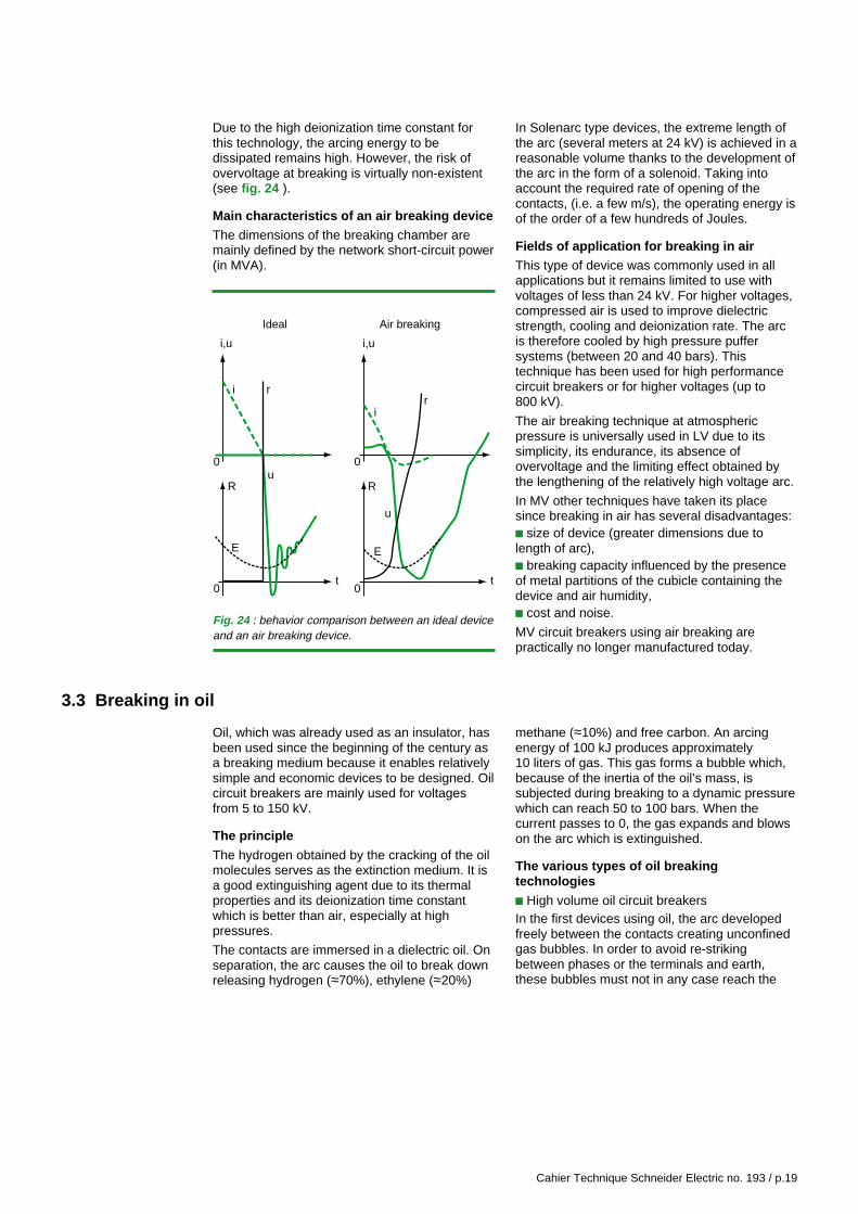
Due to the high deionization time constant forthis technology, the arcing energy to bedissipated remains high. However, the risk ofovervoltage at breaking is virtually non-existent(see fig. 24 ).
Main characteristics of an air breaking deviceThe dimensions of the breaking chamber aremainly defined by the network short-circuit power(in MVA).
In Solenarc type devices, the extreme length ofthe arc (several meters at 24 kV) is achieved in areasonable volume thanks to the development ofthe arc in the form of a solenoid. Taking intoaccount the required rate of opening of thecontacts, (i.e. a few m/s), the operating energy isof the order of a few hundreds of Joules.
Fields of application for breaking in airThis type of device was commonly used in allapplications but it remains limited to use withvoltages of less than 24 kV. For higher voltages,compressed air is used to improve dielectricstrength, cooling and deionization rate. The arcis therefore cooled by high pressure puffersystems (between 20 and 40 bars). Thistechnique has been used for high performancecircuit breakers or for higher voltages (up to800 kV).
The air breaking technique at atmosphericpressure is universally used in LV due to itssimplicity, its endurance, its absence ofovervoltage and the limiting effect obtained bythe lengthening of the relatively high voltage arc.
In MV other techniques have taken its placesince breaking in air has several disadvantages:c size of device (greater dimensions due tolength of arc),c breaking capacity influenced by the presenceof metal partitions of the cubicle containing thedevice and air humidity,c cost and noise.
MV circuit breakers using air breaking arepractically no longer manufactured today.
3.3 Breaking in oil
Oil, which was already used as an insulator, hasbeen used since the beginning of the century asa breaking medium because it enables relativelysimple and economic devices to be designed. Oilcircuit breakers are mainly used for voltagesfrom 5 to 150 kV.
The principle
The hydrogen obtained by the cracking of the oilmolecules serves as the extinction medium. It isa good extinguishing agent due to its thermalproperties and its deionization time constantwhich is better than air, especially at highpressures.
The contacts are immersed in a dielectric oil. Onseparation, the arc causes the oil to break downreleasing hydrogen (≈70%), ethylene (≈20%)
methane (≈10%) and free carbon. An arcingenergy of 100 kJ produces approximately10 liters of gas. This gas forms a bubble which,because of the inertia of the oil’s mass, issubjected during breaking to a dynamic pressurewhich can reach 50 to 100 bars. When thecurrent passes to 0, the gas expands and blowson the arc which is extinguished.
The various types of oil breakingtechnologiesc High volume oil circuit breakersIn the first devices using oil, the arc developedfreely between the contacts creating unconfinedgas bubbles. In order to avoid re-strikingbetween phases or the terminals and earth,these bubbles must not in any case reach the
Fig. 24 : behavior comparison between an ideal deviceand an air breaking device.
i
0
0
0
0
i,u
R R
i,u
i
Ideal Air breaking
rr
t t
u
u
E E

Cahier Technique Schneider Electric no. 193 / p.20
tank or join together (see fig. 25 ). Thesedevices can consequently be extremely large.
In addition to their cumbersome size, thesedevices have numerous disadvantages such asthe lack of safety due to the hydrogen producedwhich accumulates under the lid and the highlevel of maintenance necessary to monitor thepurity of the oil and maintain its dielectricproperties.
To eliminate these disadvantages (hazards,large devices), manufacturers have developedlow oil volume circuit breakers.
c Low oil volume circuit breakers
The arc and the bubble are confined in aninsulating breaking chamber. The gas pressureincreases as the arc passes through a
successive set of chambers, then it expandsthrough a duct in the arcing zone when thecurrent passes to 0. The latter is thereforeenergetically swept, thus restoring the inter-contact dielectric properties.
v Impact of the current value on breakingcapacityFor large currents, the quantity of hydrogenproduced and the corresponding pressureincreases are very high. In consequence theminimum arcing times are short.On the other hand, for small currents thepressure increases are slight and the arcing timeis long. This arcing time increases up to a criticallevel where it becomes difficult to accomplishbreaking. Complementary puffer mechanisms atthe end of the sequence can improve this point.
v Main characteristics of low oil volume circuitbreakersShort-circuit current or rated current valuesrequire the mobile contact to have a minimaldiameter. The length of the breaking chamberand the travel of the mobile components arepractically proportional to the applied voltage.To avoid excessive pressure, the minimumarcing time to break a high current must be lessthan 10 ms and it must remain less than 40 msfor critical currents.The insulating enclosure of the breakingchamber must also be designed to withstand themuch higher pressure caused by consecutivefaults, since the reduction of pressure requiresapproximately one second.However, despite the reduction in the volume ofoil, this technique still has certain drawbacks:- Oil breakdown is not reversible.- Oil breakdown and contact wear deterioratedielectric strength thus causing supplementarymaintenance costs.- In the case of quick reclosing the pole remainsat a high pressure and its breaking capacity isreduced.- The risk of explosion and fire is not completelyeliminated.
Fields of application for breaking in oil
This breaking technique has been widely used inelectrical energy transmission and distribution. Itis progressively being replaced by vacuum andSF6 breaking techniques which do not have anyof the disadvantages detailed in the precedingparagraphs.
Fig. 25 : cross sectional diagram of high oil volumecircuit breakers.

Cahier Technique Schneider Electric no. 193 / p.21
3.4 Breaking under vacuum
The dielectric properties of vacuum have beenknown for a long time and have been used e.g.in vacuum bulbs and x-ray tubes. The use ofvacuum in switchgear had been considered asearly as 1920, but it was never applied at anindustrial level until 1960 because oftechnological contingencies. Since the 1970s,the vacuum technique has been increasinglyused due to the advantages that it offers:reduced dimensions, improved safety andgreater endurance.
Dielectric properties of vacuum
In theory the vacuum is an ideal dielectricmedium: there is no substance therefore there isno electrical conduction. However, the vacuum isnever perfect and in any case has a dielectricstrength limit.
In spite of this, a true “vacuum” offersoutstanding performance levels: at 10-6 barpressure, dielectric strength in a uniform fieldcan reach a peak value of 200 kV for an inter-electrode distance of 12 mm.
The mechanism at the origin of dielectricbreaking under vacuum is linked to coldelectronic emission phenomena, without anyionization snowballing effect. This is why thedielectric strength is almost independent ofpressure as soon as the latter is less than10-6 bar. It then depends on the nature of thematerials, electrode shape (in particular thepresence of poinys or asperities) and inter-electrode distance. The shape of the curve of thebreakdown voltage as a function of the inter-contact distance (see fig. 21) shows why theapplicational scope of vacuum technologyremains limited in terms of voltage. In fact therequired distances for dielectric strengthincrease quite quickly as soon as the voltageexceeds 30 to 50 kV which leads to prohibitivecosts in relation to other technologies. In addition,more x-rays would be emitted at higher voltages.
The vacuum breaking mechanism
Breaking under vacuum is fairly unique due tothe specific characteristics of the arc undervacuum.
c Electrical arcing under vacuum
The arcing column is made up of metal vapor andelectrons coming from the electrodes as opposedto the other breaking techniques previously
discussed where this column is mainly made upof inter-contact gas ionized by collisions.It can occur in two ways, diffused arcing orconcentrated arcing, depending on the currentintensity that is present.
v For high current values (u 10,000 A) the arc isconcentrated and single, as in traditional fluids(see fig. 26a ). Cathodic and anodic spots ofseveral mm2 are raised to extremely hightemperatures. A fine layer of contact material isvaporized and the arc develops in a metal vaporatmosphere which occupies all of the space.When the current decreases, these vaporscondense on the electrodes themselves or onthe metal screen placed for this purpose. In thisarrangement, arcing voltage can reach 200 V.
v For current values less than a few thousandamperes, this arc becomes a diffuse shape. It ismade up of several arcs separated from oneanother and conical in shape with the peak at thecathode (see fig. 26b ). The cathodic roots of thearcs, called spots, have a very small surfacearea (10-5 cm2) and current density is very highthere (105 to 107 A/cm2). The extremely highlocal temperature (3,000 K) leads to very intensecombined thermo-electronic / field effectemission, though the evaporation of contactmaterial remains limited. The current is thereforebasically caused by the flux of electrons.The positive metal ions produced at the cathodehave sufficient kinetic energy (between 30 and50 eV) that they fill all of the space up to theanode. Thus they neutralize the inter-contactspace charges, resulting in a low potentialgradient and low arc voltage (80 V maximum).
Fig. 26 : concentrated arcing [a] and diffused arcing [b].
Anode
a b
Cathode

Cahier Technique Schneider Electric no. 193 / p.22
c Passing to 0 current
In a diffuse arcing arrangement, either obtainedinstantly or long enough after a singleconcentrated arc so that the metal vapor has hadtime to condense, breaking occurs easily at zerocurrent.In fact, when the current nears zero, the numberof spots decreases until the last one whichdisappears when the energy provided by the arcis no longer sufficient to maintain a high enoughtemperature at the foot of the arc. The abruptextinction of the last spot is the reason behindthe chopping phenomena frequentlyencountered with this type of technology. Itshould be noted that at voltage reversal, theanode becomes a cathode, but since it is cold itcannot emit electrons. This thus corresponds toan excessively small deionization time constant.Vacuum devices can in consequence breakcurrents with extremely high TRV gradients aswell as high frequency currents.For high currents, an arc plasma may remain at0 current and breaking becomes uncertain. It istherefore essentially the density of the residualmetal vapor which determines the breakingcapacity.
c Re-ignition and re-striking phenomena
These occur when the contacts release toomuch metal vapor. We consider that if vapordensity after zero current exceeds 1022/m3 theprobability of breaking is almost non-existent.
Generally speaking, these phenomena arealmost impossible to reproduce and difficult tomodel. Numerous tests are then required tovalidate the designs. In particular, dielectricfailures can be observed late after breaking,eventually becoming spurious, linked to thepresence of metal particles or condensationproducts.
The various types of vacuum breakingtechnologyAll manufacturers have been confronted with thesame requirements:v reducing current chopping phenomena to avoidovervoltage problems,v avoiding early erosion of the contacts tomaintain greater endurance,v delaying the appearance of the concentratedarc state to increase the breaking capacity,v limiting the production of metal vapor to avoidre-striking,v maintaining the vacuum, essential to retainingbreaking properties, throughout the device’s life.
They have developed mainly in two ways: arccontrol by magnetic field and contact materialcomposition.
c Choice of magnetic field
Two types of magnetic fields are used: radial oraxial.
v Radial magnetic field technology (see fig. 27 )The field is created by the current circulating inthe electrodes designed for this purpose. In thecase of concentrated arcing, the roots of the arcmove in a circular motion, the heat is uniformlydistributed limiting erosion and metal vapordensity. When the arc is diffused, the spotsmove freely on the surface of the cathode as if itwere a solid disk.
The fairly complex dielectrode shapes used withthis technology make dielectric strength betweenelectrodes more difficult.
I
I
B→
F→
Fig. 27 : contacts creating a radial magnetic field. Thearc obeys electromagnetic laws, therefore it movesfrom the center to the outside of the “petals”.
v Axial magnetic field technology (see fig. 28 )The application of an axial magnetic fieldrequires the ions to take a circular trajectorywhich stabilizes the diffuse arc and delays theappearance of the concentrated state. Theappearance of the cathodic spot is avoided,erosion is limited and this enables fairly highbreaking capacities to be reached.This magnetic field can be generated by internalor external bulb windings in which the currentflows permanently. Internally they must beprotected from the arc.

Cahier Technique Schneider Electric no. 193 / p.23
Radial Axialfield field
Contact resistance/ + –temperature
Arcing voltage – +
Contact erosion – +
Breaking capacity/ = =diameter
Fig. 29 : table comparing radial field and axial fieldtechnology.
Fig. 28 : contacts creating an axial magnetic field.
I
I
4 turn quarters
4 turn quarters
Axial currentincomer
I
I
Axial current feeder
Contact plates(the slits stop induced
currents flowing opposing the current flowing through the turns)
B→
B→
Externally this risk is eliminated, but in this case,dimensions are larger and limits could arise dueto the risk of the turns over-heating.The table in figure 29 compares both of thesetechnologies.
c Choice of materials
In order to maintain the quality of the vacuum, itis essential that the materials used for thecontacts and the surfaces in contact with thevacuum be very pure and gas-free.The materials that the contacts are made of isequally important since the saturating vaporpressure in the bulbs must not be too high nortoo low:
v High metal vapor pressure enables arcstabilization and limits current choppingphenomena (overvoltages).v In contrast, low metal vapor pressure is morefavorable to the interruption of high currents.Furthermore it is necessary for its resistance tobe low, for it to have a low tendency to weld andgood mechanical strength.Copper/chrome alloy contacts (50-80 % Cu,50-20 % Cr) are mainly used in circuit breakersdue to their corrosion resistance, their lowelectrical resistance and their low vapor pressure.Other materials such as copper/bismuth(98% Copper, 2% Bismuth) or more recentlyAg/W/C are used in high switching rate devices(e.g. contactors) since they do not causechopping and have a low tendency to weld.Concerning the other components in contact withthe vacuum, ceramic materials used with thehigh temperature welding process are for themoment the most suitable to maintain a highvacuum level (pressure usually less than10-6 mbar).
c Chamber and breaking device design
The key constraint is that of sealing the bulbunder vacuum: e.g. mobile inserting parts mustbe avoided.Particle sensitivity and the possibility of coldwelding means that sliding contacts are not usedunder vacuum. Consequently, the contacts are

Cahier Technique Schneider Electric no. 193 / p.24
simply placed end to end and the operatingenergy for such devices is therefore low (30 to50 J). On the other hand, contact pressure mustbe high in order to minimize contact resistanceand avoid separation of the contacts when ashort-circuit current passes. The required contactpressure leads to high mechanical stresses.Considering the small insulation distances undervacuum and the simplicity of the mechanisms,bulbs can be very compact. Their volume is afunction of the breaking capacity (bulb diameter)however it is the dielectric strength of theexternal enclosure which becomes important indefining the device size.This technology is now well mastered by majormanufacturers and the devices have a life-expectancy greater than 20 years. It must benoted that permanent monitoring of the vacuumin operation is not possible since it requires asuitable metering device and de-energizing ofthe equipment. The predictive maintenancerequired, for accidental leaks, in order to monitorthe reliability of the MV electrical switchboards istherefore not appropriate with this technology.
Fields of application for vacuum breakingThis breaking technique currently enablesdevices to be produced with great electricalendurance, and greatly increased TRVgradients.
This technique is most widely used in MV:general purpose circuit breakers are nowavailable for various applications with all of theusual breaking capacities (up to 63 kA). They areused for protection and control of:c overhead cables and lines,c transformers,c single bank capacitors,c shunt motors and inductances.They are particularly well suited for controllingarcing furnaces (high electrical endurance) butmust be used with care for controlling parallelconnected multi-bank capacitors.
This technology is also used for contactors whichrequire high endurance, but rarely for switchesfor economic reasons.In low voltage the use of this technique hasremained marginal for reasons of cost and theabsence of limiting power. Generally speaking, inLV its use is limited to the range between 800and 2,500 A rated current and for breakingcapacities less than 75 kA.High voltage applications (U to 52 kV) remain forthe future.
Comments :
c When breaking capacitive current, post-breaking dielectric strength under vacuum israndom, and leads to a high risk of re-striking.Vacuum circuit breakers are therefore poorlysuited to protection of capacitive networks withvoltages greater than 12 kV or those containingcapacitor banks .
c For vacuum contact type switches: there is arisk of welding the contacts after closing undershort-circuit conditions. This is the case incertain circumstances e.g. fault locating or duringstandards testing cycles.In fact, welding occurs when the contacts areclosed under load. When consequently openingunder no load, the lack of arcing means that theroughness, that remains from the breaking of theweld, is not eliminated. This deterioration ofsurface condition makes pre-arcing even easierduring successive closures and increases thedegree of the welding, with the risk of definitivewelding taking place.The use of these switches therefore requirescertain precautions.
c For motor control: it is necessary to takespecial precautions due to the fact that the circuitbreakers or contactors are breaking highfrequency currents (re-ignition phenomena)which therefore cause overvoltages. Eventhough there exist specific devices, it ispreferable to associate these circuit breakerswith ZnO type overvoltage protection devices.
3.5 Breaking in SF6
Sulfur hexafluoride -SF6-, is a gas that isappreciated for its many chemical and dielectricqualities. The breaking technique using this gaswas first developed in the 1970s similarly tovacuum-type breaking.
Properties of SF6
c Chemical propertiesIn its pure state SF6 is a non-polluting colorless,odorless, uninflammable and non-toxic gas. It isinsoluble in water.
It is chemically inert: all chemical bonds on themolecule are saturated and it has a highdissociation energy (+1,096 kJ/mol) as well as ahigh evacuation capacity for the heat producedby arcing (high enthalpy).
During the arcing phase, in which the temperaturecan reach between 15,000 K and 20,000 K theSF6 breaks down. This decomposition is virtuallyreversible: when the current is reduced thetemperature is reduced and the ions andelectrons can reform to make the SF6 molecule.

Cahier Technique Schneider Electric no. 193 / p.25
A small number of by-products are obtained fromSF6 breakdown in the presence of impurities likesulfur dioxide or carbon tetrafluoride. These by-products remain confined in the bulb and areeasily absorbed by active compounds, such asaluminium silicate, which are often placed in thebreaking environment.
IEC report 61634 on the use of SF6 in breakingswitchgear gives standard values which can beencountered after several years of use. Thequantities produced remain low and are nothazardous for people or the environment:air (a few ppmv), CF4 (40 ppmv to 600 ppmv),SOF2 and SO2F2 (in negligible quantities).
c Physical properties
v Thermal propertiesThe thermal conductivity of SF6 is equal to thatof air but research on SF6’s thermal conductivitycurve at high temperature reveals a peak atSF6’s dissociation temperature (see fig. 30 ).
The SF6 breaking mechanismc Electrical arcing in SF6
Thermal study of electrical arcing has enabled itto be described as being formed by a dissociatedSF6 plasma, in a cylindrical shape, made up of avery high temperature core surrounded by a coldersheath of gas. The core and the sheath areseparated by a temperature difference related tothe dissociation temperature of the molecule.Around 2,000°C this threshold remains unchangedas the current intensity varies (see fig. 31 ).During this arcing phase the sum total of thecurrent is carried by the core since the thresholdtemperature at this stage is less than theminimum ionization temperature and the externalsheath remains insulating.The characteristic magnitudes of the arc dependon the type of breaking used (self-compression,rotary arc, self-expansion) and are given in theparagraphs discussing each of these breakingtypes.
Fig. 30 : SF6 thermal conductivity curve as a functionof temperature.
0
0.5
1
1.5
2
2.5
3
3.5
4
0
Temperature (K 103)
Thermal conductivity (W cm-1 K-1 10-2)
2 4 6 8 10 12 14
Fig. 31 : temperature distribution curve of an arccontained in a cylindrical tube filled with SF6.
Arc core
Temperature(x 103K)
High electricalconductivity
15
5
2iarc < iarc < iarc
Good electricalinsulation
Very goodelectrical insulation
Ionization level
Thermalthreshold
v Dielectric propertiesSF6 has a very high dielectric gradient due to theelectronegative properties of fluorine (see fig. 21):- The life span of the free electrons remains verylow and with the SF6 molecules they form heavyions with low mobility. The probability ofdielectric failure by a snowballing effect isthereby delayed.- This gives this medium an extremely low de-ionization time constant of 0.25 ms (see fig. 19).

Cahier Technique Schneider Electric no. 193 / p.26
c Passing to 0 current
With the decrease in current, the temperature ofthe core drops and therefore electricalconductivity also begins to fall.Approaching zero current, the thermalexchanges between the sheath and the corebecome very high. The former disappearsleading to the disappearance of conductivity witha time constant that is extremely low (0.25 ms)but not sufficient to break high frequencycurrents (no re-ignition).
Various types of SF6 breaking technologyand their fields of applicationIn SF6 devices, the contacts are located within asealed enclosure filled with gas in which thepressure varies according to voltage and designparameters. These enclosures are generallysealed for life since the leakage rate can be keptto a very low level. Pressure and / or densitymeasurement systems can be installed whichenable permanent monitoring of gas pressure inthe enclosure.Several types of SF6 device technology exist,differing in terms of arc cooling methods andeach having varying characteristics andapplicational fields.
c Self compression breaking
In this type of circuit breaker, the arc is blown outby the release of a volume of SF6 compressedby a piston action: when the device opens, acylinder attached to the mobile contact movesand compresses a volume of SF6 (see fig. 32a ).A puffer nozzle channels the gas in the arc axiswhich is then ejected in the hollow contacts.At high currents, the arc causes a blocking effectwhich contributes to the accumulation ofcompressed gas. When the current nears zero,the arc is first of all cooled then extinguished dueto the injection of new SF6 molecules.The average value of the arc’s voltage isbetween 300 and 500 V.This technology enables all currents up to thebreaking capacity to be broken without anyproblems and without any critical current, sincethe energy required to blow out the arc isproduced by the mechanical order which isindependent of the current to be broken.
v Characteristic valuesThe relative pressure of SF6 generally used variesfrom 0.5 bar (16 kA, 24 kV) to 5 bars (52 kV),which enables the achievement of sealed leak-proof enclosures with guaranteed safety.
Fig. 32 : principles of self-compression [a], and rotary arc [b] breaking.
a
b
Mobile contact
Fixed contact
High pressure zonesMechanical and thermal compression
Low pressure zone
Movement of the mobile contacts
Movement of the gases
Movement of the arc

Cahier Technique Schneider Electric no. 193 / p.27
The factors influencing the dimensions of thebreaking chamber are the following:- The test voltage withstand of the input/outputwhich determines the insulation distancebetween the open contacts. It can be constantand of the order of 45 mm depending on the SF6pressure used.- The short-circuit current to be broken determinesthe diameter of the nozzle and the contacts.- The short-circuit power to be broken determinesthe puffer piston dimensions (at 24 kV thevolume of gas blast is of the order of 1liter for abreaking capacity of 40 kA).The opening energy of 200 J (16 kA) to 500 J(50 kA) remains relatively high despite thecompactness of the devices due to the energyrequired for gas compression.
v Fields of application for self-compressionbreakingThe principle of self-compression is the oldest ofthem all and has been used for all types ofgeneral purpose circuit breakers. It involvesrelatively low overvoltages since there is littlechopping phenomena and there is no risk ofsuccessive re-ignition.Self-compression circuit-breakers are well suitedto capacitor bank operation since they have alow re-strike probability as well as a highendurance to closing currents.However, the relatively high operating energyleads to quite high stresses on the operatingmechanism and possibly to a limitation in termsof the number of operations.This technology is still widely used todayespecially for high intensity devices and voltagesgreater than 24 kV.
c Rotary arc breakingIn this technology, the arc cools through its ownmovement through the SF6. The high speedrotary movement of the arc (which can exceedthe speed of sound) is caused by the magneticfield created by a winding through which the faultcurrent flows.When the main contacts open, the current isswitched to the winding and the magnetic field
appears. The resulting Laplace force acceleratesthe arc in a circular movement. The arc contactshave the shape of circular tracks which can beeither concentric (radial arc and axial field) orface to face as seen in figure 32b (axial arc andradial field). The arc is thereby cooled in auniform manner in the SF6. The device’s coolingcapacity therefore depends directly on the valueof the short-circuit current which gives thesedevices a gentle breaking capacity only requiringlow operating energy: the energy required onbreaking is completely supplied by the arc andthe low currents are broken without chopping orovervoltages.Because of the quick movement of the arc’sroots, hot spots releasing metal vapors areavoided and contact erosion is minimized inparticular in the case of axial geometry.It must be noted that nearing zero current, themagnetic field is reduced. It is important that itkeeps a non-zero value in such a way that thearc is kept moving in the cold SF6 when the TRVappears, thereby avoiding the appearance ofcritical currents This is achieved by insertingshort-circuit rings which force the magnetic fieldto be in slight phase displacement relative to thecurrent.
v Characteristic valuesIn MV, the arc rotating in SF6 has a voltage ofbetween 50 and 100 V for a length of 15 to25 mm.Due to the low breaking energy, the devices arevery compact even at a relatively low fillingpressure (of around 2.5 bar) and opening energyis less than 100 J.
v Fields of applicationRotary arc breaking is well suited to operatingdevices sensitive to overvoltages such as MVmotors and alternators. Its excellent endurance,due to low contact wear and low control energymake it of use in applications with a high numberof switching operations (contactor function).The rotary arc technique used on its own onlyenables a limited breaking capacity to beachieved (25/30 kA at 17.5 kV) and only appliesto voltages less than 17.5 kV.

Cahier Technique Schneider Electric no. 193 / p.28
c Self expansion
Self-expansion breaking uses the thermal energydissipated by the arc to increase the pressure ofa small volume of SF6 which escapes through anorifice crossed by the arc (see fig. 33a ). As longas the current in the arc is high, it has a blockingeffect which prevents the outflow of gas throughthe orifice. The temperature of the cold gasblocked in the volume increases due to thethermal dissipation of the arc (mainly byradiation), therefore its pressure increases aswell. At zero current the plug disappears and theSF6 expands and blows out the arc. The puffereffect depends on the current value, whichenables low control energy and gentle breaking,but with a risk of critical currents as well. Theseare generally found at approximately 10% of thebreaking capacity.
v Two methods of arc guiding have beendeveloped, mechanical guiding and magneticguiding, which enable the stabilization of the arcin the puffer zone as well as the elimination ofcritical currents.- Mechanical guiding (self-compression type)(see fig. 33b )The arc is maintained centered between the twocontacts by insulating walls confining thegaseous flux in a manner similar to the nozzlesused in self-compression.This technique is safe and simple but itincreases the energy required for control. In fact,the presence of these mechanisms in the arc
zone reduces the dielectric performance of theSF6 during the restoring phase, which leads toan increase in the inter-electrode gap andcontact displacement rates, and even thepressure of the SF6.- Magnetic guiding (rotary arc type)(see fig. 33c )An appropriately dimensioned magnetic fieldenables the centering of the arc in the SF6expansion zone while giving it a rapid rotationalmovement similar to that with rotary arctechnology. This technology, which requiresexpertise in design and simulation, offers theadvantage of avoiding having substances otherthan SF6 in the arcing zone. Thermodynamicefficiency is optimum and the SF6 keeps all of itsdielectric qualities. Therefore the insulationdistances can be reduced to their minimum andthe required control energy is low.
v Characteristic valuesFor low currents the puffer action is almost non-existent and arc voltage generally does notexceed 200 V.The bulb filling pressure is close to atmosphericpressure and thermal puffer volume is between0.5 and 2 liters.Control energy under 24 kV is less than 100 J.All of these characteristics mean that the self-breaking technique is the best performingtechnology to date. The breaking capacities canbe very high while still having low pressure andcontrol energy, therefore giving great reliability.
Coil
Fixed contact
Mobile contact
Movement of the mobile contact
Movement of the expanding gas
∆P
Guidingzone
Insulatingwalls
a b c
Fig. 33 : self-expansion, its principle [a] and the two methods of arc guiding, mechanical [b] and magnetic [c].

Cahier Technique Schneider Electric no. 193 / p.29
v Fields of applicationThis technology, developed for breaking faultcurrents, is well suited for breaking capacitivecurrents since it accepts overcurrents andovervoltages. It is also suitable for breakingslightly inductive currents.Without any additional means thermal expansiondevices have limited breaking capacity andoperating voltages. The self-expansiontechnique is often associated with rotary arc or
piston assisted self-compression. It is then usedin devices intended for MV and even in HV for allapplications.
The performance levels achieved by combiningthermal expansion and rotary arcing are suchthat the technique is considered for use in circuitbreakers used in extremely demandingapplications, e.g. to protect power stationalternators (high asymmetry and TRV) or forapplications requiring great endurance.
3.6 Comparison of the various techniques
Currently in the LV sector, magnetic breaking inair is, with the exception of a few rare cases, theonly technique used.
In EHV, the SF6 breaking technique is practicallythe only one used.
In MV applications, where all the technologiescan be used, SF6 breaking and vacuum breakinghave replaced breaking in air for reasons of costand space requirements (see fig. 34 ), andbreaking in oil for reasons of reliability, safetyand reduced maintenance (see fig. 35 ).
Vacuum or SF6 breaking techniques have similarperformance levels and their respective qualitiesmean that one or other is better suited for certainapplications.
According to the country, one or other of thesetechnologies is primarily used mainly forhistorical reasons or manufacturer’s choice.
100
%
80
60
40
20
0
1980
Air Oil Vacuum SF6
82 84 86 88 90 92 94 96
Fig. 34 : development of the MV circuit breaker marketin Europe.
Fig. 35 : comparison of performances of various breaking techniques.
Oil Air SF6 / Vacuum
Safety Risk of explosion and fire if Significant external effects No risk of explosion nor ofincrease in pressure (hot and ionized gas external effects.(multiple operations) causes emissions during breaking).failure.
Size Fairly large device volume. Installation requiring large Small.distances.(unconfined breaking).
Maintenance Regular oil replacement Replacement of arcing Nothing for the breaking(irreversible oil breaking-down contacts when possible. components.during each break). Regular maintenance of Minimal lubrification of the
the control mechanism. control mechanisms.
Sensitivity to The breaking environment can be changed by the environment Insensitive: sealed for life typethe environment itself (humidity, dust, etc.). bulb.
Quick cycle The long pressure reduction The slow evacuation of hot Both SF6 and the vacuumbreaking time requires de-rating of the air requires the breaking recover their dielectric
breaking capacity if there is capacity to be de-rated. properties very quickly:a risk of successive breaks. no need to de-rate the
breaking capacity.
Endurance Mediocre. Average. Excellent.

Cahier Technique Schneider Electric no. 193 / p.30
The following table figure 36 summarizes therespective features of each of these twotechniques.
v SF6 and vacuum circuit breakers are generalpurpose circuit breakers and can be adapted toall applications.Technological progress in terms of vacuum bulbproduction has enabled very reliable andcompetitive devices to be obtained in the sameway as SF6 devices.The vacuum breaking technique is easier toimplement at low voltages (voltage less than7.2-12 kV). On the other hand, the SF6 breakingtechnique enables higher breaking performances
to be more easily achieved (voltage or short-circuit current).
v Vacuum technology is widely used in controlfunctions (contactor) (moderate voltage or current,high endurance requirement) despite theprecautions to be taken concerning overvoltages.On the other hand, it is almost non-existent inswitch functions for economic reasons; inparticular, the excellent dielectric strength of SF6after breaking enables a single device to integratethe functions of switching and isolation, which isnot possible under vacuum. Today, most majormanufacturers use both these breaking techniquesin their switchgear according to their requirements.
SF6 Vacuum
Applications Motors, All. Relatively suited to high breaking All. Relatively suited to low voltagesfurnaces, performances (I and U). and very quick TRVs.lines, etc.
Circuit All. Isolating functions are prohibited.breakers,contactors,etc.
Characteristics Endurance Satisfactory for all current applications. Can be very high for certain specialapplications.
Overvoltage No risk for low inductive currents. Overvoltage protection deviceVery low probability of re-striking for recommended for motor andcapacitive currents. capacitor bank switching.
Isolation Very stable, enabling isolating functions.betweencontacts
Dimension Very compact at low voltages.
Functioning Loss of Up to 80% of performancessafety tightness maintained at Patm.
Possibility of continuous monitoring.
Maintenance Reduced for the control mechanism. Reduced for the control mechanism.Possibility of permanent monitoring Occasional control of the vacuumof gas pressure. possible.
Number of Very low (< 4/10,000), mainly due to Very low if the bulb productionfailures the auxiliaries. procedure is well controlled.
Fig. 36 : compared features of SF6 and vacuum breaking techniques.
3.7 What possibilities for other techniques?
For several decades, engineers have beenseeking to develop circuit breakers without arcsor mobile parts, notably by using electroniccomponents.
Thyristors enable breaking devices to beproduced in which the behavior can be near tothe ideal switch since they break the currentwhen it passes to zero; furthermore, theirendurance is exceptional under normalconditions of operation. Unfortunately, apart fromtheir cost, static components have a fewdisadvantages:
c high thermal dissipation,c high sensitivity to overvoltages andovercurrents,c leakage current in a blocked state,c limitation in reverse voltage.These features make it necessary to combinethem with:c radiators,c overvoltage protection devices,c ultra-quick fuses,c switches or isolators,c and of course electronic control systems.

Cahier Technique Schneider Electric no. 193 / p.31
Semi-conductors: thyristors, GTO, IGBT havemade enormous progress and are widely used inLV in various applications, e.g. to producecontactors every time the operating rate is veryhigh.
In HV, thyristors are placed in impedanceregulation control devices comprising self-reactorsand capacitors, in FACTS -Flexible AlternatingCurrent Transmission Systems-, whose role is tooptimize and stabilize the network and in CustomPower for distribution networks.
4 Conclusion
Of all the MV breaking techniques only SF6 andvacuum breaking offer significantly betterperformance levels.
The choice between vacuum and SF6 dependsentirely on the applicational field and thetechnological choices made by each country andmanufacturer: resulting in the differences ingeographic spread of the devices using SF6 orvacuum breaking techniques.
Currently no other technique capable ofreplacing vacuum or SF6 breaking is on thehorizon. These two techniques have numerousadvantages relative to the older techniques:
c Safety: no risk of explosion or fire and externaleffects during breaking.
c Compactness: vacuum and SF6 are very goodinsulators, thus the devices are not as big.
c Reliability: few moving parts and low controlenergy which means high availability, reducedmaintenance and a very long life span.
c Placing these devices in enclosures and theproduction of very compact ready-madeMV switchboards is another important advantagesince the breaking capacity is not affected by thepresence of metal partitions.Due to current computing technology, whichenables modeling and simulation, switchgear isconstantly improving.However, the most important gains in terms ofoperational dependability of installations(reliability, safety, maintainability) are related tothe widespread use of equipment that is in afactory-made and tested enclosure, associatedwith the integrated protection, monitoring andcontrol systems.
In MV, applications are very rare and staticcircuit breakers remain in the prototype phase;this is because, in addition to their weaknesseslisted above, it is necessary to use severalcomponents in series to withstand the ratedvoltage.
In conclusion, except for very specificapplications, static breaking currently does nothave a very bright future.Electrical arc breaking currently remains theunavoidable solution.

Cahier Technique Schneider Electric no. 193 / p.32
Bibliography
Standardsc IEC 60034: Rotating electrical machines.
c IEC 60056: High-voltage alternating-currentcircuit-breakers.
c IEC 60909: Short-circuit current calculation inthree-phase AC systems.
c IEC 61233 report: High-voltage alternatingcurrent circuit-breakers - Inductive loadswitching.
c IEC 61634 report: High-voltage switchgear andcontrolgear - Use and handling of sulphurhexafluoride (SF6) in high-voltage switchgearand controlgear.
Schneider Electric’s Cahiers Techniquesc Analyse des réseaux triphasés en régimeperturbé à l’aide des composantes symétriques.B. DE METZ-NOBLAT, Cahier Technique no. 18.
c The breaking process with a Fluarc SF6 puffer-type circuit-breaker.J. HENNEBERT, Cahier Technique no. 112.
c Calculation of short-circuit currents.B. DE METZ-NOBLAT, G. THOMASSET,R. CALVAS and A. DUCLUZAUX,Cahier Technique no. 158.
c Control, monitoring and protection of HV motors.J.-Y. BLANC, Cahier Technique no. 165.
c Breaking by auto-expansion.G. BERNARD, Cahier Technique no. 171.
c SF6 properties, and use in MV and HVswitchgear.D. KOCH, Cahier Technique no. 188.
c Manœuvre et protection des batteries decondensateurs.D. KOCH, Cahier Technique no. 189.
Various worksc High Voltage Circuit Breakers-Design andApplications-. RUBEN, D. GARZON.
c Disjoncteurs HAUTE TENSION : Comparaisondes différents mode de coupure.B. JOYEUX-BOUILLON (GEC ALSTHOM) &J.-P. ROBERT (Merlin-Gerin)
c Disjoncteurs SF6 : Evolution de 1959 à 1994.D. DUFOURNET, (GEC ALSTHOM- T&D).
c Manœuvre des courants capacitifs - Etat del’art -. ELECTR n°155, Août 1994.
c Etude des technologies existantes desdisjoncteurs de distribution. IREQ, Avril 1991.
c Guide technique du disjoncteur.P. POLO & P. ATTIER, 1993.


Schneider Electric Direction Scientifique et Technique,Service Communication TechniqueF-38050 Grenoble cedex 9Fax: (33) 04 76 57 98 60
DTP: AXESS - Saint-Péray (07)Edition: Schneider ElectricPrinting: Imprimerie du Pont de Claix - Claix - France - 1000- 100 FF - ©
199
9 S
chne
ider
Ele
ctric
06-9928299