munich ao rtc workshop - eso · atca system outline • advanced telecom computing architecture,...
TRANSCRIPT

Munich AO RTC WorkshopATCA Based AO RTCATCA Based AO RTC
Zoran LjusicDecember 2012
National Research CouncilCanada
Conseil national de recherchesCanada

Outline• NFIRAOS systemN OS sys e• ATCA System outline• Kermode FPGA boardKermode FPGA board• Pixel Processing• MVMMVM• CG• FD CGFD CG• New FPGA generation
Munich AO RTC Workshop 212/04/2012

Simplified NFIRAOS diagram
12/04/2012 Munich AO RTC Workshop 3

TMT RTC block diagram
The proposed solution for the Real Time Computer within NFIRAOS for TMTNFIRAOS for TMT project is ATCA based system with an FPGA processing board.
12/04/2012 Munich AO RTC Workshop 4

ATCA System Outline
• Advanced Telecom Computing Architecture, ATCA, is designed to be used in central office grade equipment.Th ATCA ifi ti V3 0 b PCI I d t i l C t• The ATCA specification V3.0 by PCI Industrial Computer Manufacturers Group, PICMG, defines the chassis form factor back plane boards powerfactor, back plane, boards, power..
• Many possible applications where high volume data need to be processed fast. p
• It can be used in Radio Astronomy and Adaptive optics.• Many modules available off-the-shelf, COTS.Many modules available off the shelf, COTS.
Munich AO RTC Workshop 512/04/2012

ATCA system- Different sizes available,6, 14 and 16 slots systems Common.
14 slot back planeBack planes provide:
Power via 48V rails
ATCA shelf with cooling fans
- Power via -48V rails- Control and data signals- Full-mesh between boards at 10 Gbps- Kermode based system 20 Gbps
Munich AO RTC Workshop 612/04/2012

Kermode ATCA board
The Kermode board was primarily developed for use in Radio Astronomy- The Kermode board was primarily developed for use in Radio Astronomy and Adaptive Optics.
- In Radio Astronomy the Kermode based ATCA computing system couldIn Radio Astronomy the Kermode based ATCA computing system could be used perform a variety of DSP tasks such are:
Beam former and filter bankCorrelatorCorrelatorPulsar binning machine
- In Adaptive Optics the Kermode based ATCA system could be used as a Real p p yTime Computer.
- The Kermode could be ordered thru Canadian company Nutaq (Lyrtech).
12/04/2012 Munich AO RTC Workshop 7

Kermode FPGA board connectivity andKermode FPGA board connectivity and block diagram
St d d Ad dTCA f f t- Standard AdvancedTCA form factor:280 X 322 mm (11.024” X 12.67”).
- High I/O bandwidth : 150Gbps Zone 2; 160Gbps Zone 3150Gbps Zone 2; 160Gbps Zone 3
- 8 Xilinx FPGAs (Virtex-6 SX475), 4 F-FPGAs (front column) and 4 R-FPGA (rear column), 1TMACs per FPGA device.
- FMC cards, each connects to an F-FPGA, for flexible I/O interfacing or f dditi l ifor additional processing power.
- Each FPGA connects to 2 DDR3 SODIMM modules at 13MB/s memory bandwidth.
- 350W power dissipation.350W power dissipation.- Monolithic heat sink
12/04/2012 Munich AO RTC Workshop 8

Interfacing with wave front sensors
- FPGA1 and FPGA2belong to the front group
of devices. Therefore one Kermode interfacesKermode interfaceswith 4 WFS.WFS data could enter the board:- From front side via- From front side via FPGA Mezzanine Card, FMC.- From rear side via Rear Transition Module RTMTransition Module, RTM.
12/04/2012 Munich AO RTC Workshop 9

Pixel Processing
Each WFS is divided in 4 quadrants.qThere are 50 sFPDP data readout frames per quadrant.A frame is made of 1024 2 byte pixels data plus header.To transfer one data frame takes 8.3µs, which is 123.45 MWords/s,or 246.9 MB/s or approx 2Gbp/s effective pixel rate
I t ti ti ftpp p p
Instantiating a soft core processor within the FPGA enables Matched Filter coefficients calculation on-the-spot.
12/04/2012 Munich AO RTC Workshop 10
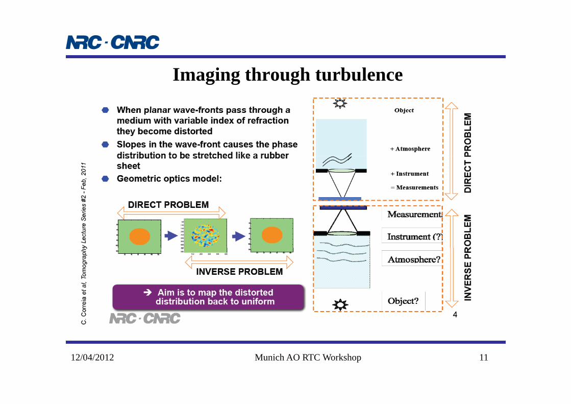
Imaging through turbulence
12/04/2012 Munich AO RTC Workshop 11

Matrix Vector MultiplicationComputing DM commands directly from slopes:
-There are 30984 slopes vector and 7093 DM actuators.- Matrix is 30984 X 7083, each element is 4 Bytes, which is 880MB.- This 2 X 30984 X 7083 Flop = 2 X 219,459,672 Flop ~ 440MFlop.p , , p p- For completing the task in 1ms the computing requirements are: 440GFlop/s and 880GB/s memory bandwidth
-The calculation could be done by using many processing engines in parallel.
12/04/2012 Munich AO RTC Workshop 12
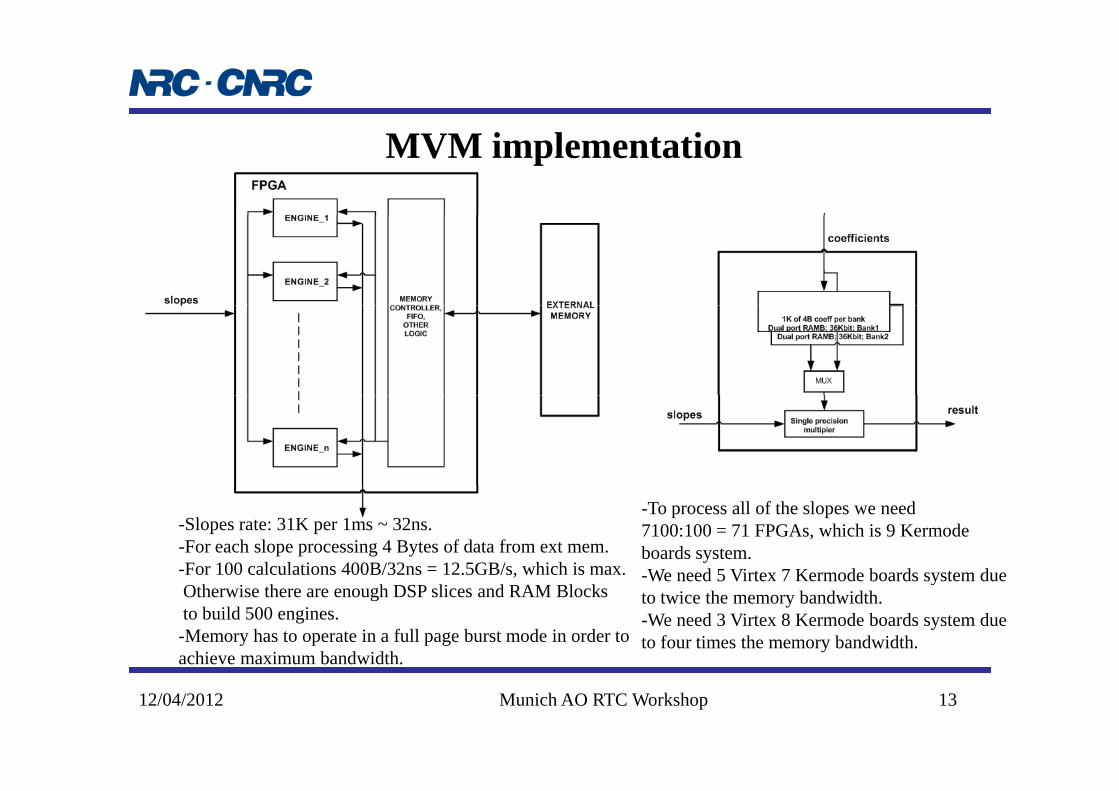
MVM implementation
-Slopes rate: 31K per 1ms ~ 32ns.-For each slope processing 4 Bytes of data from ext mem.-For 100 calculations 400B/32ns = 12.5GB/s, which is max.
-To process all of the slopes we need 7100:100 = 71 FPGAs, which is 9 Kermodeboards system. We need 5 Virtex 7 Kermode boards system due,
Otherwise there are enough DSP slices and RAM Blocksto build 500 engines.-Memory has to operate in a full page burst mode in order toachieve maximum bandwidth.
-We need 5 Virtex 7 Kermode boards system dueto twice the memory bandwidth. -We need 3 Virtex 8 Kermode boards system dueto four times the memory bandwidth.
12/04/2012 Munich AO RTC Workshop 13

Conjugate Gradient
- This is an iterative method where we first estimate phase points, tomography, and then DM commands, DM fitting.
- A recent study claims that a 20 iteration of Block-Gauss-Seidel-CG20 could be done using one Kermode board in 120µsusing one Kermode board in 120µs.
-To achieve high data bandwidth between FPGAs on the board special cables are required.-A 2 Kermode board system with a custom Zone 3 backplane should be able to perform task.
12/04/2012 Munich AO RTC Workshop 14

Fo rier Domain preconditioned CGFourier Domain preconditioned CG algorithm
-The latest simulations show that Fourier domain preconditioningcombined ith Conj gate Gradient algorithm co ld prod ce morecombined with Conjugate Gradient algorithm could produce more accurate results and be simpler to implement.
-The algorithm uses 2D FFT with Conjugate Gradient.This could be implemented in the Kermode based system- This could be implemented in the Kermode based system.
12/04/2012 Munich AO RTC Workshop 15

FD CG Implementation
- Same logic block performs FFT and IFFT.- 128 point FFT/IFFT takes 700ns. 64 FFT modules will consume 768, out of 2016, DSP slices.- To 2DFFT 128 X 128 matrix will take 2 X 2 X 700ns= 2.8µs, the same is the case forµ ,2DIFFT, so in total about 10µs to go both direction if we add some data reordering time andif we keep intermediate data in local Block RAM.
- So 3 passes of 2DFFT/IFFT would add 30µs.- This leaves enough time and logic for the rest of operations in a 2 Kermode boards system.
12/04/2012 Munich AO RTC Workshop 16
g g p y

Designing with FPGA challenges
-The devices have become more capable,and more complex.
-Many IP cores are provided by the vendor,all have to work together in a device.
-AXI bus is all but n-bit bus, differentflavors for different tasks.
-Majority of the FPGA infrastructure willMajority of the FPGA infrastructure willbe provided by the Board Support Package, BSP, leaving us to deal with red framed boxes only.
12/04/2012 Munich AO RTC Workshop 17

Xilinx roadmap
All Programmable 20nm FPGALaying the foundation for the rest of the portfolio, the core FPGA combines the 20nm
ith t f d i i tiprocess with a new set of design innovations for Xilinx’s 8 series FPGAs. These next generation devices give another 50% price-performance-per-watt improvement, twice the memory bandwidth and the nextthe memory bandwidth and the next generation of industry leading system optimized transceivers.
12/04/2012 Munich AO RTC Workshop 18