multitouching the fourth dimension - computer sciencehansona/papers/4dice-mco2012090080.pdf ·...
TRANSCRIPT
Rese aRch Fe atuRe
80 computer Published by the IEEE Computer Society 0018-9162/12/$31.00 © 2012 IEEE
4D-control interface with our multitouch-based system, we found that the multitouch interface exhibited about 1.5 times faster performance for 4D navigation tasks.
ADVANTAGES OF MULTITOUCHResearchers have investigated how multitouch meth-
ods can provide innovative user interaction in a variety of environments.1-3 With multitouch, researchers can expand significantly beyond the mouse’s two degrees of freedom and still avoid the complexity of special-purpose devices embedded in 3D space. The simultaneous use of multiple fingers for input can provide extra one-handed degrees of freedom, allowing users to circumvent two-handed meth-ods, such as the use of modifier keys to switch control contexts.
These extra degrees of freedom can be effective for applications in which the user must control data having unconventional geometry, such as 4D objects. For example, intuitively manipulating objects that are projected from a 4D model to a standard display screen requires six degrees of orientation control plus controls such as scaling, focal-length adjustment, and translation.
Because multitouch technology is highly intuitive and physically natural, it has a high adoption rate. Unlike spe-cialized interaction devices such as the space mouse and 3D wands, multitouch interface controls are ubiquitous
I nteractive computer graphics methods can effectively meet the challenge of exploring 4D worlds. Even though the physical world is only 3D, the virtual world of computer modeling can in principle represent any
imaginable higher-dimensional geometry. The problem is how to present these models in a way that enhances users’ intuitive experiences of the abstract geometric world they are trying to understand.
Multitouch interfaces can provide an excellent envi-ronment for exploring and building intuition about the geometric concepts of 4D worlds, offering a natural way to interact with the extra degrees of freedom that characterize 4D geometry. The common availability of these interfaces in handheld devices strongly motivates exploring how they might enhance a user’s 4D manipulation experience.
To test the idea that multitouch interfaces might be a more efficient way to interact with and learn about 4D objects, we designed an intuitive interactive 4D explora-tion interface and implemented an application based on this design for the iPad and iPhone. Our 4Dice application enables the user to interact with the structure of a hyper-cube or tesseract viewed as an eight-sided, back-face culled 4D die (http://itunes.apple.com/us/app/4dice/id453083422).
Our interface is the first to exploit multitouch gestures to seamlessly explore all six 4D rotational degrees of free-dom. In a user study comparing an equivalent mouse-based
The increased degrees of freedom in a multitouch interface help users control 4D worlds with intuitive gestures. Relative to a specialized mouse-based interface, a multitouch interface is easier to learn, and 4D object manipulation is up to 1.5 times faster.
Xiaoqi Yan and Chi-Wing Fu Nanyang Technological University, Singapore
Andrew J. Hanson Indiana University Bloomington
Multitouching the Fourth Dimension
SeptemBer 2012 81
and easy to master, making them a good fit for educational applications.
VISUALIZING 4D OBJECTSFrom the rich history of work on visualizing higher-
dimensional geometric models using computer graphics displays, A. Michael Noll’s examination of how to project N-dimensional objects to a graphics screen for exploration4
and Thomas F. Banchoff’s use of continuously rotating 4D mathematical objects5,6 are particularly relevant to our work. In designing our exploratory interface, we followed the core methods of these approaches, using perspective projections of 4D points, edges, and surface patches to 3D, then employing standard 3D graphics and lighting to render the result on the display screen.
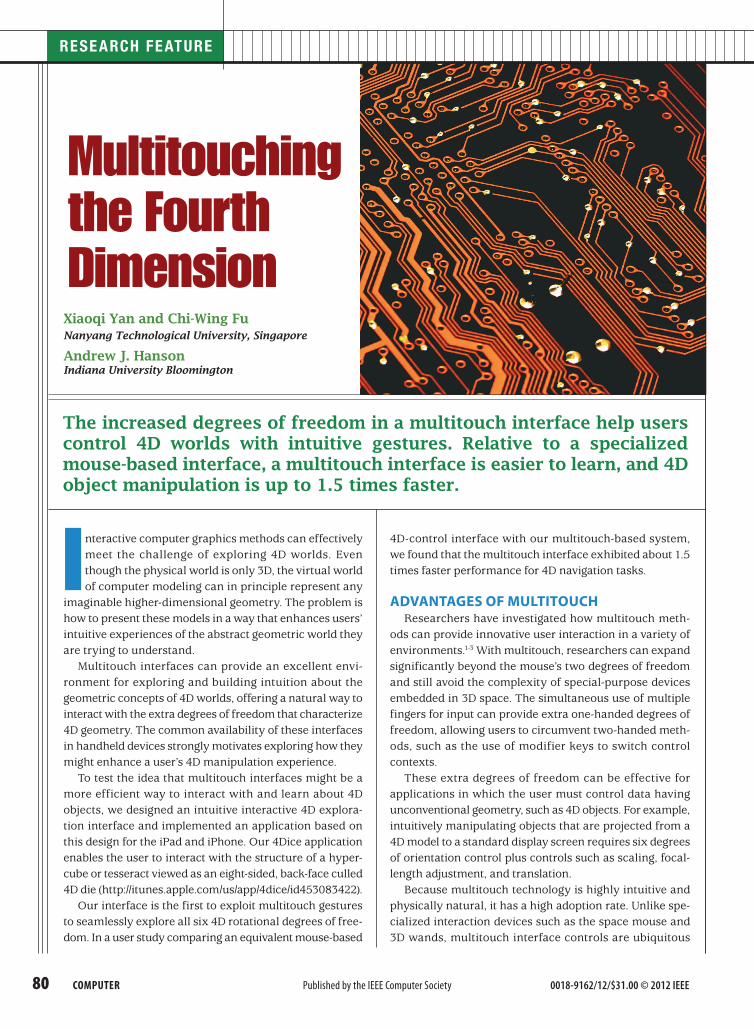
Figure 1 shows our 4D imaging pipeline, which paral-lels the familiar process of 3D imaging with the addition of one final projection to the screen space. The image of a 4D object is a voxel image in a 3D volume screen instead of a 2D pixel image as in 3D imaging. After the user rotates the 4D object as desired, our interface projects it to a 3D image that is further rotatable in 3D, so that the user can see all its aspects in the final projection from the intermediate 3D voxel image to the 2D display.
In 4D imaging, a 4 × 3 matrix implements orthogonal projection to eliminate a 4D directional line of sight, instead of the 3 × 2 projection matrix typical of 3D imaging. To produce perspective projection, we divide by the 4D dis-tance between a rendered element and the 4D viewpoint instead of by the 3D distance to the 3D viewpoint.
In 3D, if two curves have points that lie on coincident lines of sight, the nearer curve technically shadows the more distant one. Such curves can share a point in the 2D projected image even though they are far apart in 3D. Similarly, a pair of noncolliding 4D surface patches can share a curve embedded in the 3D projection where the two surfaces appear to intersect, with the nearer patch shadowing the other.
Geometry of 4D worlds Those who dabble in the fourth dimension often hear
questions such as, “Is the fourth dimension real?” or “4D can’t be like the ordinary world, so it has to be time, right?”
The assumption is that 4D cannot be “real” because people are not familiar with visualization beyond 3D. However, once a piece of mathematics is inside the computer, it is as real as any other piece of mathematics inside that computer. Thus, one geometric data representation might consist of vertex points as 3D vectors; another might have vertex points as 10D vectors, as in string theory. All dimensions are real as far as the computing framework is concerned.
The interface between the mathematics inside the com-puter and the outside world that an observer can sense defines the connection with reality—the transformation from mathematical 4D models to the 2D computer screen. 3D stereoscopic displays are also possible, but here we assume a 2D screen on a handheld device.
Six 4D rotation parameters Because we can express an arbitrary rotation in any
dimension as a composition of rotations in planes defined by pairs of orthogonal Euclidean coordinate axes, we can specify all the 4D rotational degrees of freedom by six in-dependent parameters, corresponding to the rotations in the planes labeled wx, wy, wz, yz, zx, and xy. In addition to the 3D subspace rotations, yz, zx, and xy, three new ma-trices effectively tilt the w-axis into the direction of the x-, y-, and z-axes.
The wx 4D rotation matrix is
cos θ 0 0 sin θ 0 1 0 0 0 0 1 0–sin θ 0 0 cos θ
R (θ, wx) = ,
and the wy and wz rotations are permutations of this. Multiplying R(θ,wx) into a pure w column-vector (0,0,0,w)t produces a small positive x component (w sin θ) for small θ, and similarly multiplying a pure x column-vector (x,0,0,0)t
gives a small negative w component (–x sin θ).
4D back-face cullingA comprehensive simulation of 4D lighting and shad-
ing automatically removes the 3D parts of the scene that cannot reflect light to the 4D viewer.7 In 3D graphics sys-tems such as OpenGL, enabling back-face culling removes the invisible polygons, which have normal vectors pointing
Figure 1. The 4D imaging pipeline from mathematical model to visualization and interaction. The pipeline is the exact parallel of the 3D imaging process with an additional final projection.
Rotationin 4D
Projection4D to 3D
Rotationin 3D
Projectionto screen
Visualization andinteraction
(on 2D screen)Geometry
(in 3D)Geometry
(in 3D)Geometry
(in 4D)Geometry
(in 4D)
82 computer
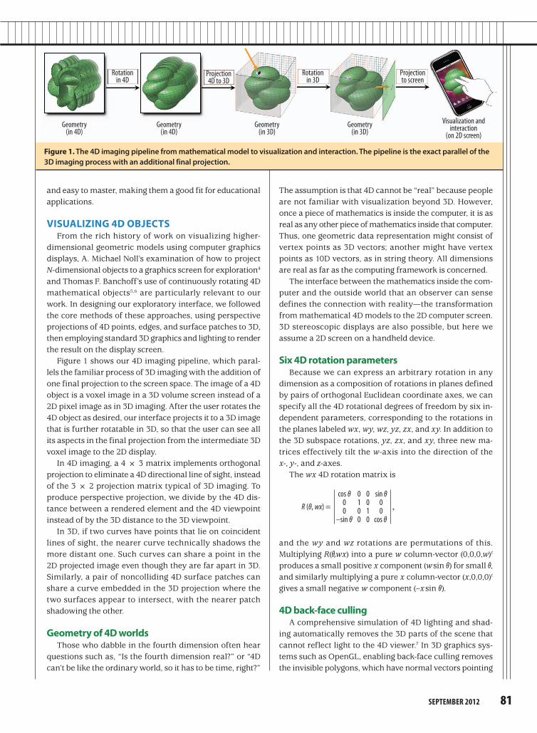
Figure 2. Rolling ball controller geometry. (a) 3D rolling ball controller geometry on a 2D screen and (b) 4D rolling ball con-troller geometry on a 3D screen.
Rese aRch Fe atuRe
of putting a ball on a table, placing a flattened horizontal palm on top of the ball, and rotating the ball incrementally by moving the hand to the right for a positive y-axis (zx-plane) rotation, and toward the user for a positive x-axis (yz-plane) rotation. Moving the hand in clockwise horizontal circles produces counterclockwise rotations in the xy-plane (about the z-axis). Clearly, a mouse-based implementation of this algorithm permits rotations in all three planes, thus achiev-ing any 3D orientation with a finite sequence of 2D motions.
In 4D, the precise analog of the 2D vector that controls the 3D rolling ball orientation is a 3D vector that controls the 4D rolling ball.9 Imagine a 4D object projected to 3D space along the w-axis, which is “pointing out at you” and therefore invisible, just as the 3D z-axis is for the 3D case. Then, as Figure 2b shows, to explore 4D orientations, we specify a 3D drag vector
dx = (dx, dy, dz),
which tilts the w-axis slightly in the plane defined by the direction dx and the w-axis itself. This action hides an old piece of geometry on the side toward which this vector is moving, and makes a new piece of geometry appear on the 3D image’s opposite side. This is exactly analogous to the 3D rolling ball, except that the 3D projection screen, not the 2D screen, is the canvas.
Finding all the 4D degrees of freedom4D orientations have six degrees of freedom, so how
can the 4D rolling ball, which apparently rotates only in three planes (wx, wy, and wz), generate the other three degrees of freedom? In fact, moving the controller in circles in the plane of any pair of control directions such as (dx, dy) will produce a rotation in that plane. Thus, because the three degrees of freedom (dx, dy, dz) correspond in pairs to the three missing planes (yz, zx, and xy), it is possible to incrementally produce rotations in all six planes (wx, wy, wz, yz, zx, and xy), and therefore to reach any possible 4D orientation.
4D INTERFACE DESIGN AND IMPLEMENTATION
To achieve our goal of designing a fluid multitouch inter-face for interacting with 4D geometry, the first step was to
away from the viewer. In four dimensions, it is similarly important to implement the 4D equivalent of back-face culling when constructing the projection of an object to the 3D image; our approach implements 4D back-face culling to produce a more accurate visual impression.
Back-face culling by itself can ensure correct visibility if the object being rendered is a solid convex polyhedron in 3D or a corresponding solid convex polytope in 4D. More complicated scenes require depth buffering in addition to back-face culling.
For a typical convex 4D polytope such as the hypercube, many of the polyhedra that would appear in a wireframe rendering disappear in any given back-face culled render-ing. Applying 4D rotations to the hypercube causes the culled parts to reappear in the appropriate sequence. No more than four of the eight cubes that make up the hyper-cube’s visible parts can appear at any one time.
The 4D rolling ballFigure 2a shows the 3D rolling ball method,8 which
suggests a particularly interesting control mode for 4D rota-tions. In 3D, the rolling ball implements the physical process
z – hidden
y
x
r
(a)
dx
dy
dy
dz
z
dx
w – hidden
y
xr
(b)
dx
dx
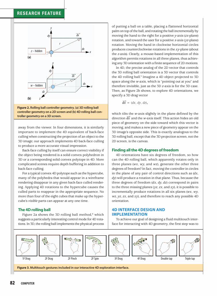
Figure 3. Multitouch gestures included in our interactive 4D exploration interface.
1F Drag 2F Drag 2F Pinch 2F Spin 3F Drag 4F Drag Double tap Triple tap
SeptemBer 2012 83
apart or together scales the screen space, so the user can more easily examine details. A four-finger drag enables the translation of 2D screen space, a double-tap resets the 3D orientation, and a triple-tap resets the 4D orientation (see Figure 1).
MASTERING THE HYPERCUBE WITH MULTITOUCH
The hypercube, or tesseract, is a familiar 4D object that generalizes the 3D cube. As an application of our 4D multitouch interface, we chose to create an educational scenario in which every aspect of a 3D die, represented as a numerically labeled 3D cube and manipulated using the 3D rolling ball, has a parallel realization in a 4D hypercube manipulated with our interface.
Just as it is possible to view a 3D cubic die as three axes, (x,y,z) ranging from +1 to –1, with square surfaces pasted on the two ends of each axis, for a total of six square faces, so it is possible to view a 4D hypercubic die as four axes, (x,y,z,w), with solid cubic “faces” pasted on the two ends of each axis, for a total of eight cubic faces.
Our approach to making the 4D hypercube more famil-iar is based on first providing an interactive approach to understanding the geometric features of a 3D die. We can then use these 3D intuitions to provide a basis for interac-tive exploration and understanding of the hypercube by treating it simply as a 4D die.
decide which functions we absolutely had to support at the top level of multiple-finger touching and dragging. We then chose those actions that had to be available without switching modes and set aside those that we could rel-egate to alternative modes, menus, and sliders. Figure 3 shows our basic vocabulary of multitouch gestures. The “Exploring the 4D World” sidebar lists some resources that can aid in understanding the research methods we used.
3D screen controlA primary design requirement was to have 3D control
of the projected image, in which a default parallel projec-tion simply chops off the fourth coordinate and displays the object geometry in terms of the first three coordi-nates. Thus, rotating in this 3D subspace of 4D is the same as rotating the 3D projected image. It is therefore natural to allow users to rotate the object geometry in 3D with a one-finger drag, in the same general fashion as dozens of existing touch-based (and mouse-based) 3D geometry systems. Although other 3D image control options are available, we chose to use the context-free 3D rolling ball.
4D control design We characterized the remaining three 4D rotational
degrees of freedom as rotations in the wx-, wy-, and wz-planes. Because any wx rotation mixes the x-component in the projected image and the hidden w-component, x and w continually change places with one another as θ increases monotonically. The same is true for wy rota-tions, enabling the clean control of any combination of wx and wy rotations with a two-finger drag on the screen’s natural xy coordinate system.
Finally, the wz coordinate rotations fill out the six- parameter rotation space. There is a natural correspon-dence between “spinning” the screen around its center and familiar actions such as turning a drill brace-and-bit or a screwdriver. Such motions have one fixed center and a moving curved path around that center. Thus, we chose a two-finger action with one finger fixed as a perfect intuitive realization of this type of z-direction screw motion. It is a two-finger action, just like the wx and wy motions, but in gesture analysis, multitouch software can easily separate it from an action in which both fingers are moving.
4D perspective, screen space adjustment, and reset
To make exploration easier, we added several more multi- touch controls, exhausting our chosen vocabulary. The most important was 4D perspective adjustment, associated with three-finger up-down dragging, which changes the 4D perspective transformation from orthogonal (pushing away, to the top of the screen) to high-perspective dis-tortion (pulling toward the bottom). Two fingers moving
Exploring thE 4D WorlD
e fforts to understand the fourth dimension have stimulated a rich variety of thoughts and insights—from artistic treat-
ments of the hypercube to a spectrum of novel implementation methods exploited in or suggested by our work.
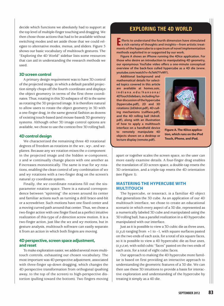
Figure A shows an iPhone running the 4Dice application. For those who desire an introduction to manipulating 4D geometry, our eponymous YouTube video offers a one-minute conceptual overview of the back-face culled hypercube as a 4D die (www. youtube.com/watch?v=fx7ehl7YvMY).
Additional background and mathematical details for select-ed topics covered in this article are available at homes.soic. i n d i a n a . e d u / h a n s o n a / 4DTouchSidebars, including fur-ther discussion of the hypercube (hypercube.pdf), 2D and 3D rotations (2d3drot.pdf), 4D cull-ing mechanisms (cullface.pdf), and the 4D rolling ball (4droll.pdf), along with an illustration of how to apply a multitouch interface on a handheld device to remotely manipulate 4D objects shown on a desktop or lecture display (remote.pdf).
Figure A. The 4Dice applica-tion, which runs on the iPod Touch, iPhone, and iPad.

Rese aRch Fe atuRe
84 computer
Understanding the ordinary cube as a 3D die Figure 4a shows a single 3D die, which contains six
square faces numbered so that opposite pairs sum to seven. One, two, or at most three of these are visible at any one time if back-face culling is enforced. Spinning about the x (or 1:6) axis reveals the numbered faces in the cyclic re-peating order 3:2:4:5. Spinning about the y (or 2:5) axis reveals the faces in the cyclic order 3:6:4:1. Performing a counterclockwise circular xy-plane rolling ball action reveals the 1:2:6:5 faces “peeking” around the edges of face 3 as the die spins slowly clockwise about the z-axis.
Understanding the hypercube as a 4D die To understand the hypercube as a 4D die, we can repeat
the 3D process by exact analogy, attempting to make the strangeness of 4D geometry as familiar as 3D geometry. Figure 4b shows how to envision a 4D die as having four axes—x, y, z, and w—instead of three. Consequently, there are four pairs of labels, one pair for the two ends of each axis.
Opposite labels sum to nine. The opposite labels sum to nine instead of seven. A 4D gambler would be very familiar with the rule that opposite ends of the x-axis are labeled by 1 and 8, the y-axis by 2 and 7, the z-axis by 3 and 6, and the w-axis by 4 and 5.
Faces are cubes, not squares. The geometric objects at the ends of the axes are cubes instead of squares. At the ends of the 3D cube’s three axes are square 2D faces. In
4D, the dimensions increase by one for everything, so the face objects at the ends of the hypercube’s four axes are 3D cubes. Thus, hypercube faces are cubic volumes instead of square surfaces.
Solid cubic faces are drawn as transparent. The hyper-cube faces technically are solid cubic volumes, so we need to “look inside them” to see the numbering because the numbers label the cube’s body rather than the surface. For that reason, we drew these solid objects as transpar-ent wireframe cubes and represented the numeric labels as small solid spheres floating inside.
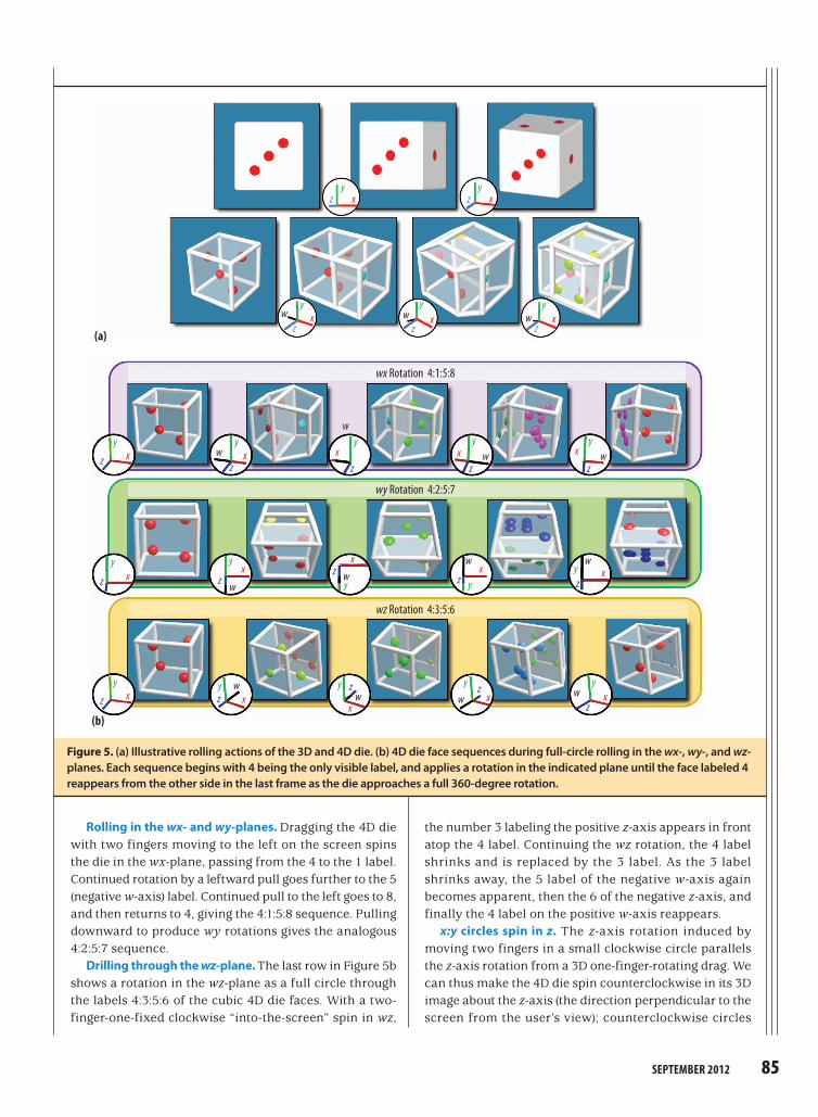
The rolling dieFigure 5a shows the simplest possible set of views for a
3D and a 4D die and the small rotations connecting them. A 3D die can show one face, rotate slightly to show a second face, and rotate slightly in another direction to show a third face; only three faces can appear at any one time. The 4D die possesses one more rotation direction, so up to four cubic face volumes can appear simultaneously, but no more.
Figure 5b shows the sequence of cubic faces and nu-meric labels that appear for each basic motion, wx-plane rotation, wy-plane rotation, and wz-plane rotation. In each case, in the left-to-right sequence, the number 4 labeling the positive w-axis becomes invisible as the rotation pro-gresses, and then reappears in the fifth frame as the die approaches a full 360-degree rotation.
Figure 4. (a) The basic geometry, visual presentation, and face-numbering rules of a 3D right-handed die. Opposite ends of the x-axis are labeled 1 and 6, the y-axis ends are 2 and 5, and the z-axis ends are 3 and 4. The darkened faces (4, 5 ,6) are those that 3D back-face culling has removed. (b) The basic geometry, visual presentation, and face-numbering of a 4D right-handed die. Opposite ends of the x-axis are labeled 1 and 8, the y-axis ends are 2 and 7, the z-axis ends are 3 and 6, and the w-axis ends are 4 and 5. The solid cubes represented as green-colored wire frames (5, 6, 7, 8) are those that 4D back-face culling removes.
A rolling 4D die1, 2, 3, and 4 are front faces
(a)
(b)1 and 8 2 and 7 3 and 6
A rolling 3D die1, 2, and 3 are front faces
1 and 6 2 and 5 3 and 4
4 and 5
yz x
yz
xw
SeptemBer 2012 85
the number 3 labeling the positive z-axis appears in front atop the 4 label. Continuing the wz rotation, the 4 label shrinks and is replaced by the 3 label. As the 3 label shrinks away, the 5 label of the negative w-axis again becomes apparent, then the 6 of the negative z-axis, and finally the 4 label on the positive w-axis reappears.
x:y circles spin in z. The z-axis rotation induced by moving two fingers in a small clockwise circle parallels the z-axis rotation from a 3D one-finger-rotating drag. We can thus make the 4D die spin counterclockwise in its 3D image about the z-axis (the direction perpendicular to the screen from the user’s view); counterclockwise circles
Rolling in the wx- and wy-planes. Dragging the 4D die with two fingers moving to the left on the screen spins the die in the wx-plane, passing from the 4 to the 1 label. Continued rotation by a leftward pull goes further to the 5 (negative w-axis) label. Continued pull to the left goes to 8, and then returns to 4, giving the 4:1:5:8 sequence. Pulling downward to produce wy rotations gives the analogous 4:2:5:7 sequence.
Drilling through the wz-plane. The last row in Figure 5b shows a rotation in the wz-plane as a full circle through the labels 4:3:5:6 of the cubic 4D die faces. With a two-finger-one-fixed clockwise “into-the-screen” spin in wz,
Figure 5. (a) Illustrative rolling actions of the 3D and 4D die. (b) 4D die face sequences during full-circle rolling in the wx-, wy-, and wz- planes. Each sequence begins with 4 being the only visible label, and applies a rotation in the indicated plane until the face labeled 4 reappears from the other side in the last frame as the die approaches a full 360-degree rotation.
(a)
(b)
wx Rotation 4:1:5:8
wy Rotation 4:2:5:7
wz Rotation 4:3:5:6
yz x
yz x
y
zxw
y
zxw
yx
w
y
z
w
y
zxw
y
zxw
y
z x
y
z x
y
z x
xy
zwx
y
zwx
z
yx
wz
x
wz
yw
z
yx
w
z
yxw
z
y xw
z
yxw
z
y
x

Rese aRch Fe atuRe
86 computer
males and three females with a mean age of 26.7 years, used multitouching. Group G2, consisting of five males and five females with a mean age of 26.2 years, used a mouse and keyboard combination.10
All participants were at least somewhat familiar with both interaction methods, and none had used our multi-touch interface before the study. Two participants had some basic knowledge of 4D (which we determined by asking them to draw a hypercube), so we split them between G1 and G2.
Each participant went through learning, practice, and task phases.
Learning phaseIn this phase, which took approximately 20 minutes,
we first presented the geometry of a hypercube as a 3D cube generalization and discussed the characteristics of a 3D die and a 4D die. We then interactively demonstrated the assigned interaction control (multitouch, or mouse and keyboard) and how participants could use them to ma-nipulate a cube represented as a 3D die and a hypercube represented as a 4D die.
Practice phaseWe then gave the participants five minutes to practice
rotating the 4D die using the group’s assigned interaction method. The initial view presented the front face of the 4D die labeled 5.
Task phaseIn this phase, which took approximately 60 min-
utes, we gave the participants a task sheet with these instructions:
This is a test of your ability to rotate a 4D die to find a
particular view with the interface control. It has 140 trials
altogether, and in each trial, you will see a 4D die with a
random number facing you and a goal number displayed at
the top of the screen. Your task is to apply the interaction
controls you just learned to quickly rotate the 4D die so
that you can clearly see the dots in the face with the goal
number. When you find the goal number, immediately press
the done button and then press the start button when you
are ready to go on to the next trial. If the number you found
is incorrect, an error message will be displayed and you
have to continue the rotation to look for the goal number.
When you are ready to start these trials, press the start
button displayed below.
To make up the 140 trials, we first created 28 trials with initial state face numbers from 1 to 4 and target goal numbers assigned to the seven remaining numbers. We repeated this process five times and presented the resulting 140 cases to the participants in a random order.
produce a clockwise z rotation. If the 4 label is showing, the 1, 2, 8, and 7 labels are visible peeking around the edges of 4 in sequence with the counterclockwise circle. The 5 label remains hidden on the far side of w, opposite the 4 label in 4D space. Starting with any other cubic face produces the appropriate sequence of four neighboring labels peeking around the edges.
Accelerometer control option. When only 4D orien-tation control is needed, the accelerometer available in many handheld devices enables controlling the entire set of three 4D rotation actions at once, producing a w-axis tilt in any direction. The 3D directional information from an incremental accelerometer motion provides an arbi-trary value of dx , no longer restricted to any Cartesian subspace, as input to the 4D rolling ball algorithm. An internal gyroscope can correct for device orientation changes, which the accelerometer might confuse with acceleration.
Figure 6 shows the correspondences between each multitouch 4D action and our chosen screen-centered Car-tesian coordinates.
USER STUDYTo test the efficiency of our multitouch interface design,
we recruited 20 participants and randomly divided them equally into two groups. Group G1, consisting of seven
Figure 6. Using two-finger multitouch controls to produce 4D rotations in the wx-, wy-, and wz-planes. Two-finger dragging in the x or y directions in the screen plane changes 4 to 1 or 8, or to 2 or 7, respectively, and one-finger-fixed spinning produces an effective z direction drag that changes 4 to 3 or 6. Continuing further in any direction will expose the 5 on the opposite end of the w-axis from 4.
+y drag shows 7
+x drag shows 8
–y drag shows 2
–x drag shows 1
–z clockwisespin shows 3
+z counterclockwisespin shows 6
y
x
z

SeptemBer 2012 87
the user-declared final view) for the two interfaces, with the result that the multitouch interface offers accuracy comparable to that of the mouse and keyboard interface.
We averaged the accuracy values over the 140 trials for each participant, and then performed a matched-paired t-test on the two sets of 10 averaged accuracy values (per participant) from G1 and G2. The mean values (and stan-dard deviations) for the accuracy of the multitouch versus mouse and keyboard interfaces were 14.58 (12.14) and 13.76 (11.13) degrees, respectively. The t-value was 0.2861 with nine degrees of freedom, indicating no significant difference between the two sets of accuracy values.
Multitouch interfaces provide the opportunity to perform complex manipulations of virtual environments, such as those representing
mathematical models of 4D objects. We have proposed an effective interface design supporting interactive exploration of 4D objects and their properties, and developed an application to facilitate the understanding of a hypercube as a 4D analog of a 3D rolling die. A unique feature of our hypercube interface is the inclusion of 4D back-face culling, which both simplifies the representation that the user sees and more accurately represents the 4D analog of what is apparent in the 3D world.
The participants had to press a start button to begin, but they could press the done button at will. The testing environ-ment detects if the participant has reached the goal number by checking the angular difference (in degrees) between the goal hyperface’s normal direction and the view direction of the 4D projection, accepting matches below a threshold angle, typically 45 degrees.
Results and analysis Our testing interfaces recorded each
trial’s start and end times, the accuracy (the angular difference between the final view and the goal description), the initial and goal numbers, and the number of times that the error message displayed.
To compare the data from the two inter-faces, we first applied a moving window average of size 15 to the raw data to com-pensate for the noise in the time data. We then computed the average time taken and the standard errors in the times for the 10 participants in each group. This yielded the smoothed sampled values T
1(k) and T2(k) for G1 and G2, respectively, for k ε [1, 140]. To further analyze the asymptotic perfor-mance and the learning rate, we performed least-squares fits on the mean curves (T1(k) and T2(k)) using the exponen-tial model
T(k) = a e–b k + c.
Figure 7 shows the results with standard errors dis-played as error bars. We plotted only the first 100 of the 140 trials, since the curves beyond that are almost flat, with negligible changes in asymptotic performance.
An examination of the two curves’ asymptotic trends reveals that the multitouch interface is roughly 1.5 times faster than the mouse and keyboard interface. To in-vestigate further, we conducted a paired t-test on the data from trial 101 to trial 140 compared with the null hypothesis—the proposition that the mean values of the trial times for the two distinct interfaces are the same. The p-value was 0.0001 (39 degrees of freedom), and the difference between the mean trial times was statistically highly significant. Hence, we rejected the null hypothesis and concluded that the mean trial times for the two interfaces are significantly different, thus providing evidence that the multitouch interface enables better performance.
We also compared the average accuracy (quantified by the angular differences between the ideal goal and
Figure 7. Time to reach a goal number for participants using mouse and key-board versus multitouching. For the mouse and keyboard, trial time averaged 5.96 ± 0.11 seconds and the exponential fit coefficient was 0.0696 ± 0.004 per trial. For multitouching, trial time averaged 3.82 ± 0.09 seconds and the expo-nential fit coefficient was 0.1088 ± 0.008 per trial. Both curves show asymptotic performance.
Trial number (10 subjects in each group)
Mou
se +
keyb
oard
: Mult
itouc
h tim
e to t
arget
0 5 10 15 20 25 30 35 40 45 50 55 60 65 70 75 80 85 90 95 10010
5
10
15
20
Mouse + keyboardMouse + keyboard �t to exponentialMultitouchMultitouch �t to exponential
Rese aRch Fe atuRe
88 computer
8. A.J. Hanson, “The Rolling Ball,” Graphics Gems III, D. Kirk, ed., Academic Press, 1992, pp. 51-60.
9. A.J. Hanson and R.A. Cross, “Interactive Visualization Meth-ods for Four Dimensions,” Proc. 4th IEEE Conf. Visualization (VIS 93), IEEE, 1993, pp. 196-203.
10. A.J. Hanson, K. Ishkov, and J. Ma, “Meshview: A Portable 4D Geometry Viewer in OpenGL/Motif”; http://homes.soic.indiana.edu/hansona/meshview/meshview.pdf.
Xiaoqi Yan is a doctoral candidate in the School of Computer Engineering at Nanyang Technological University, Singapore. Her research interests include computer graphics, interactive interfaces, and mathematical visualization. Yan received a BSc in computer science and technology from Sichuan University, Chengdu. Contact her at [email protected].
Chi-Wing Fu is an assistant professor in the school of com-puter engineering at the Nanyang Technological University, Singapore. His research interests include computer graphics, visualization, and human-computer interaction. Fu received a PhD in computer science from Indiana University Bloomington. He is a member of the IEEE Computer Society and ACM. Contact him at [email protected].
Andrew J. Hanson is a professor emeritus of computer sci-ence in the School of Informatics and Computing at Indiana University Bloomington. His research interests include the visualization of abstract concepts in mathematics and phys-ics, exploitation of quaternions, virtual astronomy, and the design of user interfaces for visualization applications. Hanson received a PhD in theoretical physics from Massachusetts Institute of Technology. He is a member of the IEEE Computer Society and ACM. Contact him at [email protected].
In future work, we hope to explore incorporating other polychora (4D regular polytopes) besides the hypercube, interacting effectively with more complicated objects such as the other polychora, and simulating 4D physical dynamics.
AcknowledgmentThe work was supported by the MOE AcRF Tier1 grant (RG 13/08), Singapore.
References 1. B. Buxton, Multitouch Systems That I Have Known and
Loved, tech. report, Microsoft Research, 2007; www. billbuxton.com/multitouchOverview.html.
2. J.Y. Han, “Low-Cost Multitouch Sensing Through Frustrated Total Internal Reflection,” Proc. 18th ACM Symp. User Inter-face Software and Technology (UIST 05), ACM Press, 2005, pp. 115-118.
3. S. Lee, W. Buxton, and K.C. Smith, “A Multitouch Three-Dimensional Touch-Sensitive Tablet, Proc. Conf. Computer-Human Interface (CHI 85), ACM Press, 1985, pp. 21-25.
4. A.M. Noll, “A Computer Technique for Displaying N-Dimen-sional Hyperobjects,” Comm. ACM, Aug. 1967, pp. 469-473.
5. T.F. Banchoff, “Visualizing Two-Dimensional Phenomena in Four-Dimensional Space: A Computer Graphics Approach,” Statistical Image Processing and Computer Graphics, E. Wegman and D. Priest, eds., Marcel Dekker, 1986, pp. 187-202.
6. T.F. Banchoff, Beyond the Third Dimension: Geometry, Computer Graphics, and Higher Dimensions, Scientific Am. Library, 1990.
7. A.J. Hanson and P.A. Heng, “Illuminating the Fourth Dimen-sion,” IEEE Computer Graphics & Applications, July 1992, pp. 54-62.
Selected CS articles and columns are available for free at http://ComputingNow.computer.org.
NEW from
SOFTWARE TESTINGEdited by Rob OshanaPulls together nine articles from authorita-tive IEEE-CS publications that add depth to one’s understanding of the topics within the Software Testing Knowledge Area of the SWEBOK Guide. With an original introduc-tion and an annotated list of valuable ad-ditional reading.
ES0000038 • 80 pp. • $29 ($19 members)
Order Online:http://bit.ly/zqj7u6