multistorey buildings
DESCRIPTION
Columns: columns, site and shop splices, column bases, anchoringtypes.Bracings: classification (first and second order) frames, distribution offorces into vertical bracings, detailing of diagonal and frame bracings.TRANSCRIPT

Multi storey buildings
Florea Dinu Lecture 12: 24/02/2014
European Erasmus Mundus Master Course
Sustainable Constructions under Natural Hazards and Catastrophic Events
520121-1-2011-1-CZ-ERA MUNDUS-EMMC
L10 – B.2 – Mechanical properties of cast iron, mild iron and steel at historical structures
European Erasmus Mundus Master Course
Sustainable Constructions under Natural Hazards and Catastrophic Events
L11 - 2C08 Multi storey buildings
Part II – Multistorey buildings
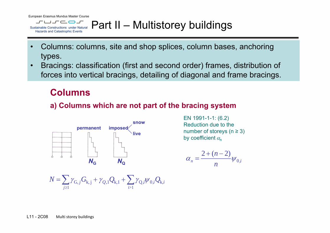
• Columns: columns, site and shop splices, column bases, anchoring types.
• Bracings: classification (first and second order) frames, distribution of forces into vertical bracings, detailing of diagonal and frame bracings.
EN 1991-1-1: (6.2) Reduction due to the number of storeys (n ≥ 3) by coefficient n
1 i>1G, ,1 Q 0k, j k,1 k,
jj Q ,i ,i iN G Q Q
snow permanent imposed live
NG NQ
Columns
02 ( 2)
n ,inn
a) Columns which are not part of the bracing system

L10 – B.2 – Mechanical properties of cast iron, mild iron and steel at historical structures
European Erasmus Mundus Master Course
Sustainable Constructions under Natural Hazards and Catastrophic Events
L11 - 2C08 Multi storey buildings 3
b) Column as members of a braced bay frame
imperfection load caused by gravity load (partly permanent)
ik,i0,1>i
iQ,k,1,1kGmax QQGN Q
ik,i0,1>i
iQ,kinfG,min QGN
Minimal (in some cases tension may result): NG,min NQ NW
NG,max
snow wind permanent imposed imposed live possible sway imperfections
c) Columns as member of a continuous frame Internal forces: N, M, V.

L10 – B.2 – Mechanical properties of cast iron, mild iron and steel at historical structures
European Erasmus Mundus Master Course
Sustainable Constructions under Natural Hazards and Catastrophic Events
L11 - 2C08 Multi storey buildings 4
Tension only:
2. Axial force and bending moment N, My or N, My, Mz
Column cross-sections 1. Axial force only (compression) (advantageous iy ≈ iz)
Steel column at “Freedom Tower” building, New York
(biaxial bending)
L10 – B.2 – Mechanical properties of cast iron, mild iron and steel at historical structures
European Erasmus Mundus Master Course
Sustainable Constructions under Natural Hazards and Catastrophic Events
L11 - 2C08 Multi storey buildings 5
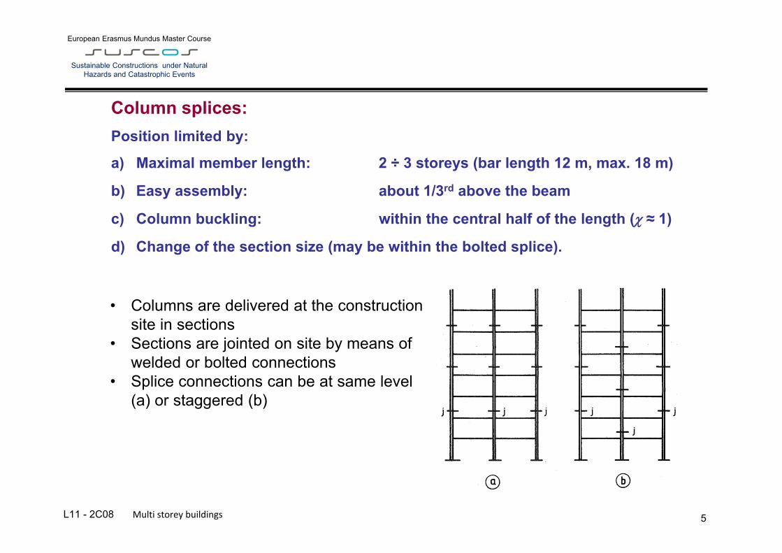
Column splices:
Position limited by:
a) Maximal member length: 2 ÷ 3 storeys (bar length 12 m, max. 18 m)
b) Easy assembly: about 1/3rd above the beam
c) Column buckling: within the central half of the length ( ≈ 1)
d) Change of the section size (may be within the bolted splice).
• Columns are delivered at the construction site in sections
• Sections are jointed on site by means of welded or bolted connections
• Splice connections can be at same level (a) or staggered (b)

L10 – B.2 – Mechanical properties of cast iron, mild iron and steel at historical structures
European Erasmus Mundus Master Course
Sustainable Constructions under Natural Hazards and Catastrophic Events
L11 - 2C08 Multi storey buildings 6
Welded splice (field weld, cut normal to the member length, eventually frontal milling) 1. Butt weld
leaned cut in the web
hollow section detail:
optional erection device flat bar / angle
constant
2. Fillet weld, flange plate splice (not suitable for columns in tension – lamellar tearing)
hollow section
optional erection device
optional erection device fixes desired positioning
≥ t
t

L10 – B.2 – Mechanical properties of cast iron, mild iron and steel at historical structures
European Erasmus Mundus Master Course
Sustainable Constructions under Natural Hazards and Catastrophic Events
L11 - 2C08 Multi storey buildings 7
3. Bolted, flange plate splice hollow section
Bolted spliced connection
Columns sections are identical a) double cleat bolted connection b) single cleat bolted connection c) single cleat and cap plate bolted
connection
Columns sections are different d) double cleat bolted connection e), f) single cleat and cap plate bolted
connection

L10 – B.2 – Mechanical properties of cast iron, mild iron and steel at historical structures
European Erasmus Mundus Master Course
Sustainable Constructions under Natural Hazards and Catastrophic Events
L11 - 2C08 Multi storey buildings 8
Splice connection verification
1) Connections usually designed for contact bearing only. Where:
a) connection within the mid half-height: L/4
L/4 L
b) small slenderness ( = Lcr / i < 80),
c) small eccentricity (bending moment respectively):
EdEd 2
N hM
2) Resistance of connections in tensions or with larger moments must be verified.
Contact bearing connection is designed (eg. weld or bolts) for shear only (if any)
where h is taken conservatively as the overall depth of the smaller column
Ed.compressiveEd
2Ed
NMFh
Eg. for splice the flange covers plates and their fasteners should be checked for: Or column splices with ends not prepared for bearing - figure
Ed.compressiveEd
2Ed
NMFh

L10 – B.2 – Mechanical properties of cast iron, mild iron and steel at historical structures
European Erasmus Mundus Master Course
Sustainable Constructions under Natural Hazards and Catastrophic Events
L11 - 2C08 Multi storey buildings 9
Column base
Base plates transfers the load to a concrete block. pinned base - plain bases (free rotation) Base plates fixed base - stiffened or gusseted base (moment bearing)
Pinned base
Usually not completely free rotation (small rotations assumed).
Lcr ≈ h Lcr ≈ 0,7 h
anchor (hook)
t flexible levelling mortar – grout (0,1 0,2 b) fc
fixed for assembly

L10 – B.2 – Mechanical properties of cast iron, mild iron and steel at historical structures
European Erasmus Mundus Master Course
Sustainable Constructions under Natural Hazards and Catastrophic Events
L11 - 2C08 Multi storey buildings 10
Design and resistance verification
Eurocode procedure: Effective area Aeff and strength of concrete under concentrated compression including grout fjd.
Minimal effective area: Design bearing strength of concrete: grout thickness ≤ 0,2 b Foundation joint material coefficient j = 2/3 if: fck grout ≥ 0,2 fck concrete
jd
Edef f
NA f
Rdujjd ff
concentrated design strength of concrete (EN 1992)

L10 – B.2 – Mechanical properties of cast iron, mild iron and steel at historical structures
European Erasmus Mundus Master Course
Sustainable Constructions under Natural Hazards and Catastrophic Events
L11 - 2C08 Multi storey buildings 11
Concentrated design strength of concrete fRdu (EN 1992-1-1):
cdc0c1cdRdu 0,3/ fAAff
Ac0 - loading area (Aeff, may be considered by A - the base plate area) Ac1 - maximal load delivery area of shape similar to Ac0 at depth h h ≥ (b2 - b1) means load delivery at 45º h ≥ (d2 - d1)
Ac0
Ac1
b1
d1
d2 ≤ 3d1
b2 ≤ 3b1
h
axis of loading

L10 – B.2 – Mechanical properties of cast iron, mild iron and steel at historical structures
European Erasmus Mundus Master Course
Sustainable Constructions under Natural Hazards and Catastrophic Events
L11 - 2C08 Multi storey buildings 12
Effective area
fjd
c
t N
c c
b
a
Aeff
For elastic behaviour of the base plate: bending moment: bending resist.: results in:
2jd2
1 cfm
M0y
2
6/ftm
M0jd
y
3 ff
tc
The verification procedure is iterative:
1. choosing of base plate dimensions a x b (eg. A ≈ NEd/fcd), 2. design bearing strength of concrete fjd, 3. choosing of plate thickness t → determining of c (section expand), 4. necessary effective area verification: Aeff ≥ NEd/fjd, 5. possible refinement of plate dimensions a x b or thickness t. → 2.

L10 – B.2 – Mechanical properties of cast iron, mild iron and steel at historical structures
European Erasmus Mundus Master Course
Sustainable Constructions under Natural Hazards and Catastrophic Events
L11 - 2C08 Multi storey buildings 13
Stiffened base
Base plate thickness usually under t ≤ 50 mm. If not satisfactory, stiffeners are used:
Design of the base plate: - effective area procedure, extension c of the stiffeners area included:
Aeff
c c extension of the section
+ stiffeners area Note.: Stiffeners loaded by M, V. (at the connection to the column)
false
diaphragm inside/outside
deformation line

L10 – B.2 – Mechanical properties of cast iron, mild iron and steel at historical structures
European Erasmus Mundus Master Course
Sustainable Constructions under Natural Hazards and Catastrophic Events
L11 - 2C08 Multi storey buildings 14
Shear resistance for base plates
• friction (compressive reaction): (friction coefficient Cf,d = 0,2)
• shear in the anchor bolt: may be designed as additional to the friction
EN 1993-1-8 gives resistance for n bolts = n Fvb,Rd
(where Fvb,Rd is reduced resistance in shear and bearing) in cases where the bolt holes are not oversized • block or bar shear connector:
may be designed as additional to the friction verification of internal forces (V, M = V e)
Edc,df, NCV
profile I, U, L
V V V N
e

L10 – B.2 – Mechanical properties of cast iron, mild iron and steel at historical structures
European Erasmus Mundus Master Course
Sustainable Constructions under Natural Hazards and Catastrophic Events
L11 - 2C08 Multi storey buildings 15
Column assembly at the concrete block - packs (packs made of plate or preferably flat bar), - holding plate (t ≈ 6 mm, for base plates less than ≈ 500 mm, placed together with the
anchor bolts embedded to the concrete, holes D+5 mm), - anchor bolt nut (for smaller base plate dimensions). Grout p ≈ 0,1b filled form plate sides or using a hole in the base plate (diameter
min. 70 mm).
packs holding plate anchor bolt nut

L10 – B.2 – Mechanical properties of cast iron, mild iron and steel at historical structures
European Erasmus Mundus Master Course
Sustainable Constructions under Natural Hazards and Catastrophic Events
L11 - 2C08 Multi storey buildings 16
Anchor bolts a) Non-structural (no significant load, resp. compression only):
common for typical columns of multi-storey buildings.
b) Load-bearing: tension mostly, by bending or for tensile columns.
Non-structural (smaller load): diameters M16 ÷ M30
a) Anchor bolts embedded in concrete - tolerances ± 50 mm (for bolts interconnected by plate tolerance ± 15 mm) b) Additionally encased anchor bolts - tolerance ± 15 mm
pin
15
50 d
> 2d
hole d + 100
L10 – B.2 – Mechanical properties of cast iron, mild iron and steel at historical structures
European Erasmus Mundus Master Course
Sustainable Constructions under Natural Hazards and Catastrophic Events
L11 - 2C08 Multi storey buildings 17
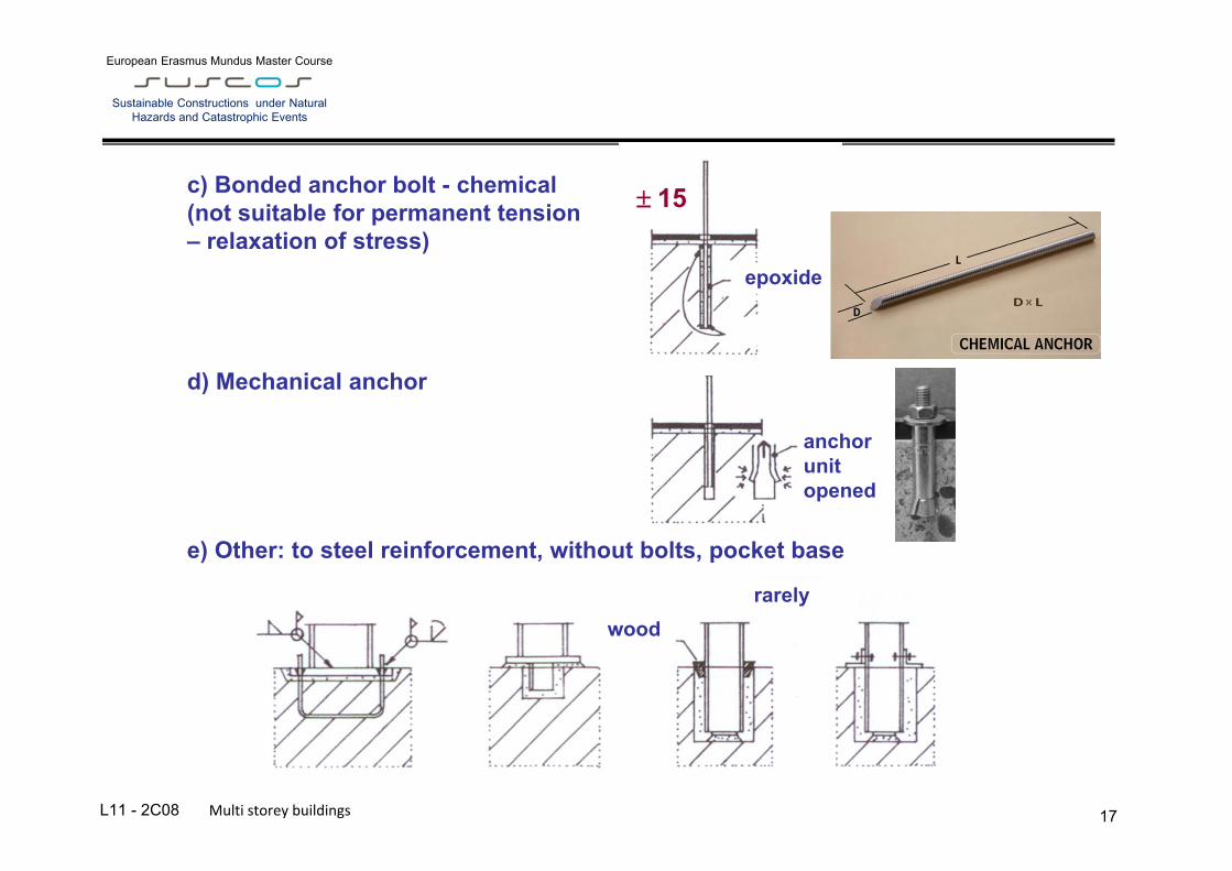
c) Bonded anchor bolt - chemical (not suitable for permanent tension – relaxation of stress) d) Mechanical anchor e) Other: to steel reinforcement, without bolts, pocket base
rarely wood
anchor unit opened
epoxide
15
L10 – B.2 – Mechanical properties of cast iron, mild iron and steel at historical structures
European Erasmus Mundus Master Course
Sustainable Constructions under Natural Hazards and Catastrophic Events
L11 - 2C08 Multi storey buildings 18
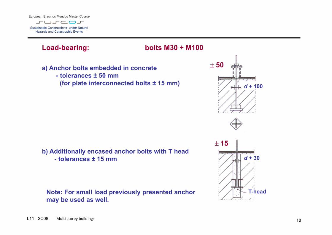
Load-bearing: bolts M30 ÷ M100
a) Anchor bolts embedded in concrete - tolerances ± 50 mm (for plate interconnected bolts ± 15 mm) b) Additionally encased anchor bolts with T head - tolerances ± 15 mm
Note: For small load previously presented anchor may be used as well.
T-head
d + 30
15
d + 100
50
L10 – B.2 – Mechanical properties of cast iron, mild iron and steel at historical structures
European Erasmus Mundus Master Course
Sustainable Constructions under Natural Hazards and Catastrophic Events
L11 - 2C08 Multi storey buildings 19
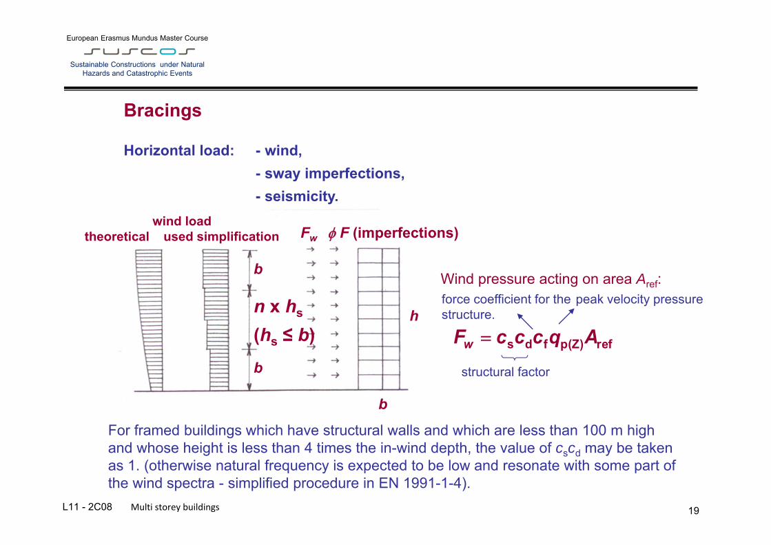
Bracings
Horizontal load: - wind, - sway imperfections, - seismicity.
Wind pressure acting on area Aref:
refp(Z)fds AqcccFw
structural factor
force coefficient for the structure.
peak velocity pressure
For framed buildings which have structural walls and which are less than 100 m high and whose height is less than 4 times the in-wind depth, the value of cscd may be taken as 1. (otherwise natural frequency is expected to be low and resonate with some part of the wind spectra - simplified procedure in EN 1991-1-4).
wind load theoretical used simplification
b
h
Fw F (imperfections)
n x hs
(hs ≤ b) b
b

L10 – B.2 – Mechanical properties of cast iron, mild iron and steel at historical structures
European Erasmus Mundus Master Course
Sustainable Constructions under Natural Hazards and Catastrophic Events
L11 - 2C08 Multi storey buildings 20
Bracings
Structural systems used to resist lateral loads: a) continuous or wind-moment frames, b) shear walls, c) braced-bay frames. Combinations of these systems may also be used (dual frame structures).
Eccentric X braced Inverted V
L10 – B.2 – Mechanical properties of cast iron, mild iron and steel at historical structures
European Erasmus Mundus Master Course
Sustainable Constructions under Natural Hazards and Catastrophic Events
L11 - 2C08 Multi storey buildings
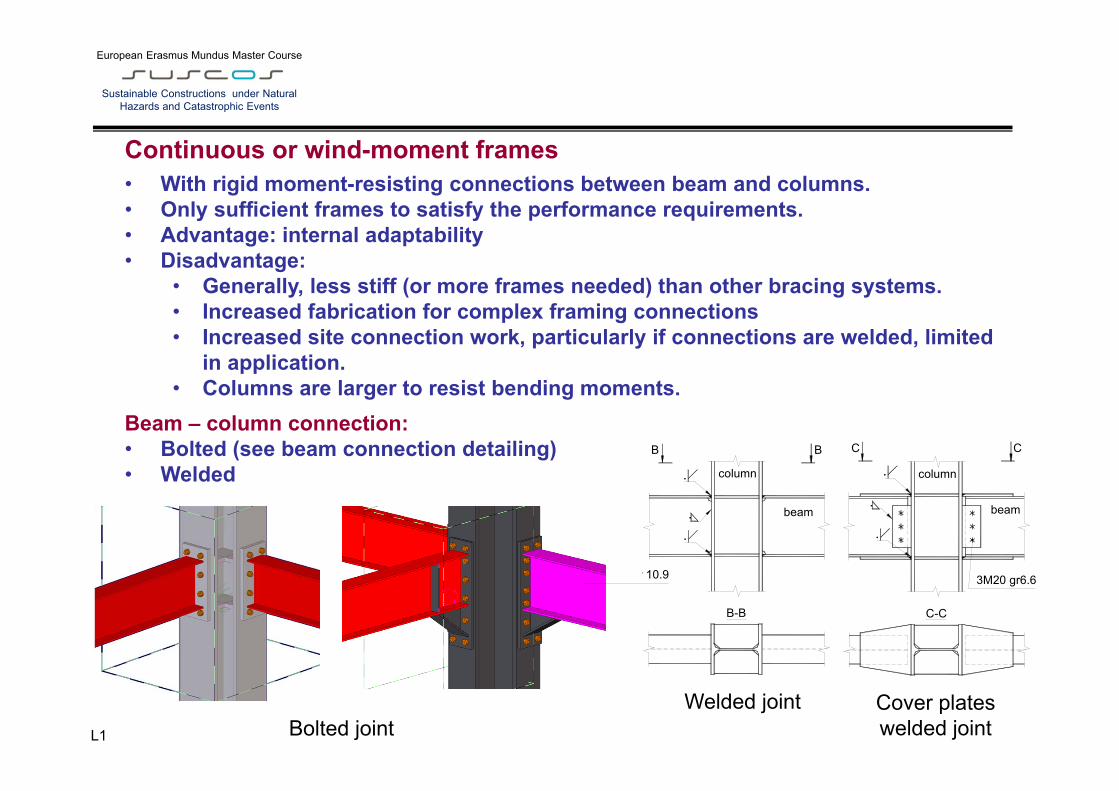
Continuous or wind-moment frames
• With rigid moment-resisting connections between beam and columns. • Only sufficient frames to satisfy the performance requirements. • Advantage: internal adaptability • Disadvantage:
• Generally, less stiff (or more frames needed) than other bracing systems. • Increased fabrication for complex framing connections • Increased site connection work, particularly if connections are welded, limited
in application. • Columns are larger to resist bending moments.
Beam – column connection: • Bolted (see beam connection detailing) • Welded
r 10.9
.
.
beam
column
.
B-B
BB
3M20 gr6.6
.
.
beam
column
.
C-C
CC
Welded joint Cover plates welded joint Bolted joint
L10 – B.2 – Mechanical properties of cast iron, mild iron and steel at historical structures
European Erasmus Mundus Master Course
Sustainable Constructions under Natural Hazards and Catastrophic Events
L11 - 2C08 Multi storey buildings 22
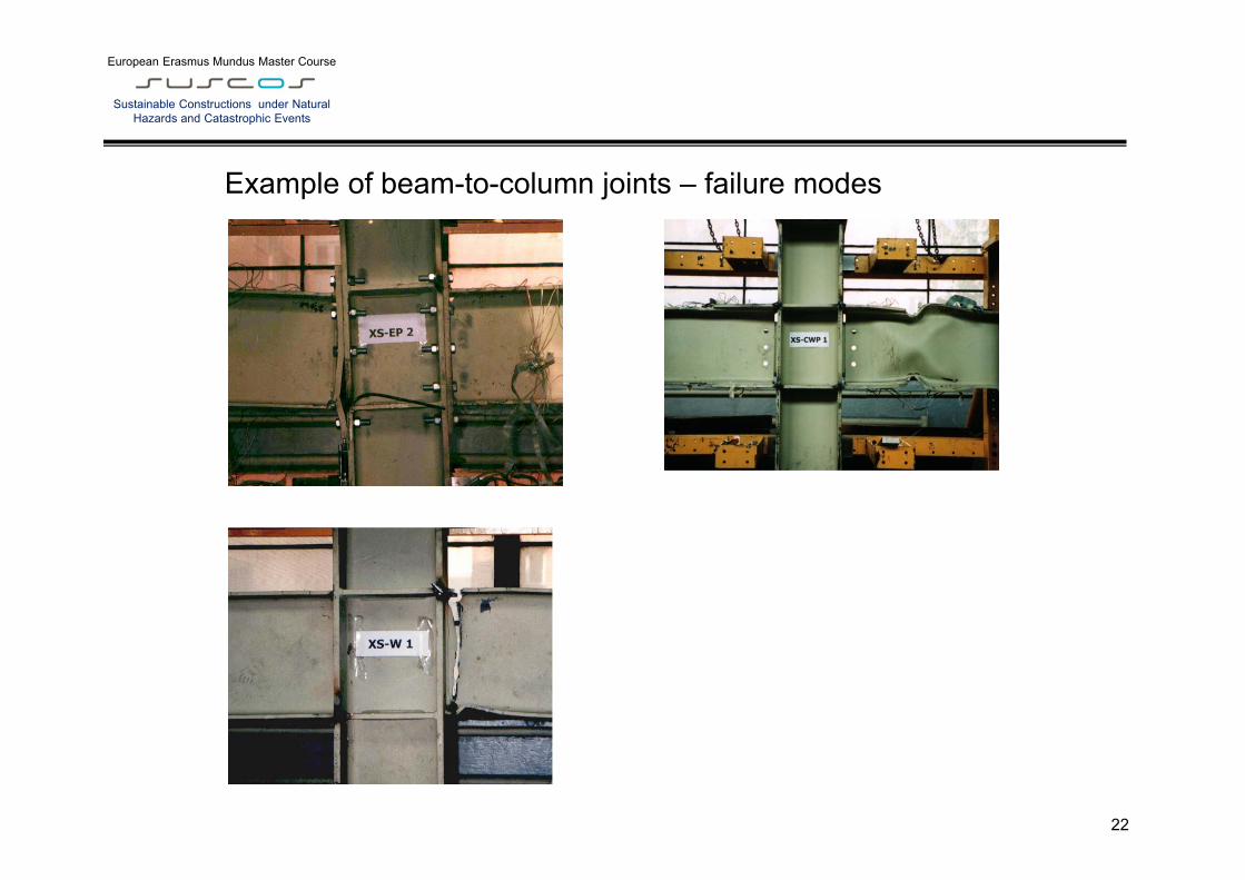
Example of beam-to-column joints – failure modes

L10 – B.2 – Mechanical properties of cast iron, mild iron and steel at historical structures
European Erasmus Mundus Master Course
Sustainable Constructions under Natural Hazards and Catastrophic Events
L11 - 2C08 Multi storey buildings 23
Shear walls (steel, concrete) Reinforced concrete walls • Constructed to enclose lift, stair and service cores • Generally possess sufficient strength and stiffness to
resist the lateral loading. • Advantages:
• Very rigid and highly effective. • Act as fire compartment walls.
• Disadvantages: • The construction is slow and less accurate than
steelwork. • Difficult to modify in the future. • Difficult to provide connections between steel and
concrete to transfer the large forces generated.
Steel shear walls • May be used instead of concrete walls • High initial stiffness and good ductility (high dissipative
seismic system) • May be integrated in the steel framing system • Disadvantageous behaviour in case of fire
L10 – B.2 – Mechanical properties of cast iron, mild iron and steel at historical structures
European Erasmus Mundus Master Course
Sustainable Constructions under Natural Hazards and Catastrophic Events
L11 - 2C08 Multi storey buildings 24
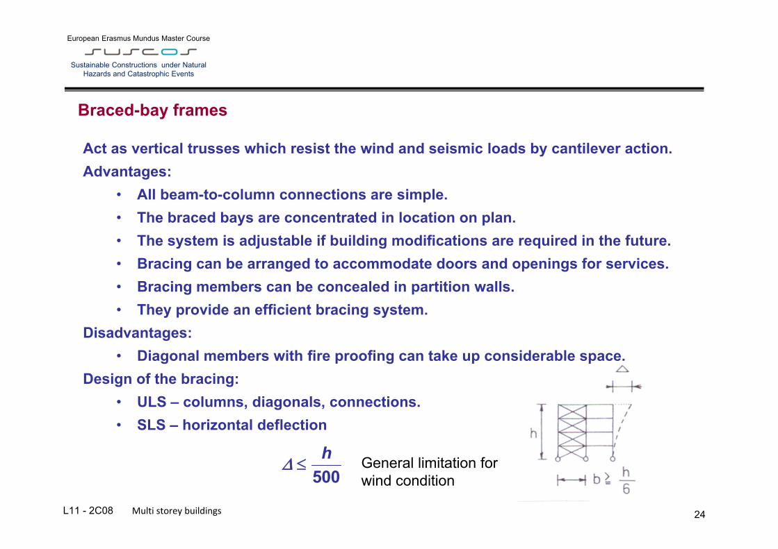
Braced-bay frames
500h
Act as vertical trusses which resist the wind and seismic loads by cantilever action. Advantages:
• All beam-to-column connections are simple. • The braced bays are concentrated in location on plan. • The system is adjustable if building modifications are required in the future. • Bracing can be arranged to accommodate doors and openings for services. • Bracing members can be concealed in partition walls. • They provide an efficient bracing system.
Disadvantages: • Diagonal members with fire proofing can take up considerable space.
Design of the bracing: • ULS – columns, diagonals, connections. • SLS – horizontal deflection
General limitation for wind condition
L10 – B.2 – Mechanical properties of cast iron, mild iron and steel at historical structures
European Erasmus Mundus Master Course
Sustainable Constructions under Natural Hazards and Catastrophic Events
L11 - 2C08 Multi storey buildings 25
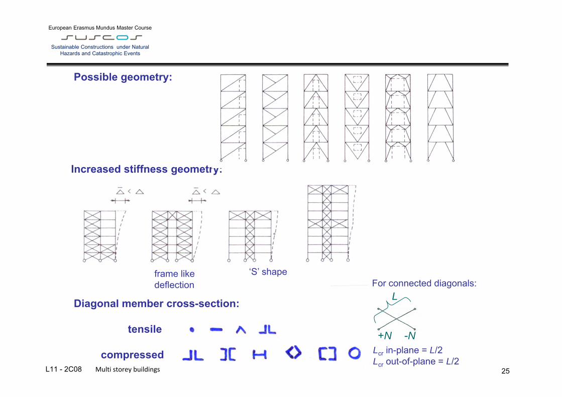
Increased stiffness geometry:
Diagonal member cross-section: tensile compressed
For connected diagonals:
Lcr in-plane = L/2 Lcr out-of-plane = L/2
+N -N
L
Possible geometry:
frame like deflection
‘S’ shape

L10 – B.2 – Mechanical properties of cast iron, mild iron and steel at historical structures
European Erasmus Mundus Master Course
Sustainable Constructions under Natural Hazards and Catastrophic Events
L11 - 2C08 Multi storey buildings 26
Internal forces (symmetric geometry, antisymmetric load, considering the horizontal load only):
W
cos
WD 21
(axial deformation neglected)
For low buildings compressed diagonal member may be neglected (lower stiffness – bigger deflection):
cosWD
cosWD
21
Special requirements - to be used as part of the seismic resistant system – see EN 1998-1

L10 – B.2 – Mechanical properties of cast iron, mild iron and steel at historical structures
European Erasmus Mundus Master Course
Sustainable Constructions under Natural Hazards and Catastrophic Events
L11 - 2C08 Multi storey buildings 27
Detailing:
small angle bigger angle
analogically for V - brace
semi-rigid connection
bigger angle
flange cutt
small angle
connection carries also the vertical component of reactions from diagonals
osa svaru
svar

L10 – B.2 – Mechanical properties of cast iron, mild iron and steel at historical structures
European Erasmus Mundus Master Course
Sustainable Constructions under Natural Hazards and Catastrophic Events
L11 - 2C08 Multi storey buildings 28
Ed
y
cr
y
NAf
NAf
cr
Possible buckling consideration directly from LBA:
(existing tables and expressions)
Global analysis - effects of deformed geometry of the structure 1. first-order analysis, using the
initial geometry of the structure
10Ed
cr FF
cr 10Ed
cr FF
cr
Lcr ≤ h
h
Lcr > h
H
or equivalent column method:
� for members: • Ncr/(MNEd) ≥ 25 no buckling.
• Buckling length taken system length (distance between the nodes/supports is
generally conservative).
2. second-order analysis, taking into account the influence of the deformation of the structure
L10 – B.2 – Mechanical properties of cast iron, mild iron and steel at historical structures
European Erasmus Mundus Master Course
Sustainable Constructions under Natural Hazards and Catastrophic Events
L11 - 2C08 Multi storey buildings 29
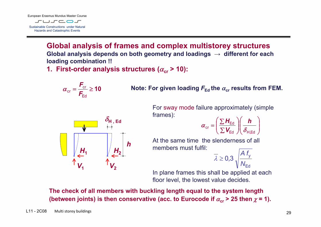
For sway mode failure approximately (simple frames):
At the same time the slenderness of all members must fulfil:
In plane frames this shall be applied at each floor level, the lowest value decides.
Global analysis of frames and complex multistorey structures Global analysis depends on both geometry and loadings → different for each loading combination !! 1. First-order analysis structures (cr > 10):
10Ed
crcr F
F
EdH,Ed
Edcr
h
VH
Note: For given loading FEd the cr results from FEM.
Ed
y
NfA
,30
The check of all members with buckling length equal to the system length (between joints) is then conservative (acc. to Eurocode if cr > 25 then = 1).
H1 H2
V1 V2
h
H , Ed

L10 – B.2 – Mechanical properties of cast iron, mild iron and steel at historical structures
European Erasmus Mundus Master Course
Sustainable Constructions under Natural Hazards and Catastrophic Events
L11 - 2C08 Multi storey buildings 30
2. Second-order analysis structures (cr < 10): In general three methods may be used:
a) Geometrical non-linear analysis with imperfections (GNIA). Second order effects considering global and member imperfections are then
included in resulting internal forces and moments. Check of individual members is done for simple compression or bending (without , LT, no stability check is necessary). The solution is demanding on software, introduction of imperfections and evaluation of results.
(a) Sway imperfections
L e0
N
(b) Member imperfections

L10 – B.2 – Mechanical properties of cast iron, mild iron and steel at historical structures
European Erasmus Mundus Master Course
Sustainable Constructions under Natural Hazards and Catastrophic Events
L11 - 2C08 Multi storey buildings 31
b) Geometrical non-linear analysis (GNIA) with global imperfection only (using frame sway or equivalent horizontal forces). Members shall be checked on buckling (i.e. 2nd order effect and influence of imperfections), taking the system length as buckling length (e.g. h, L/2).
If 3 ≤ cr< 10 and sway buckling mode (corresponds to cr determined from approximate relation above) the 2nd order effects from sway may be evaluated approximately in accordance with following method:
hcr ≤ h
fictitious support for subsequence check of members for buckling
Note: for small slopes (up to 15º or flat rafters) the Lcr equals distance of columns.
b1) Second order sway effects due to vertical loads may be calculated by increasing the horizontal loads HEd (e.g. wind) with an equivalent loads VEd due to imperfections and other possible sway effects according to first order theory by second order factor:
111
1
cr
L10 – B.2 – Mechanical properties of cast iron, mild iron and steel at historical structures
European Erasmus Mundus Master Course
Sustainable Constructions under Natural Hazards and Catastrophic Events
L11 - 2C08 Multi storey buildings 32
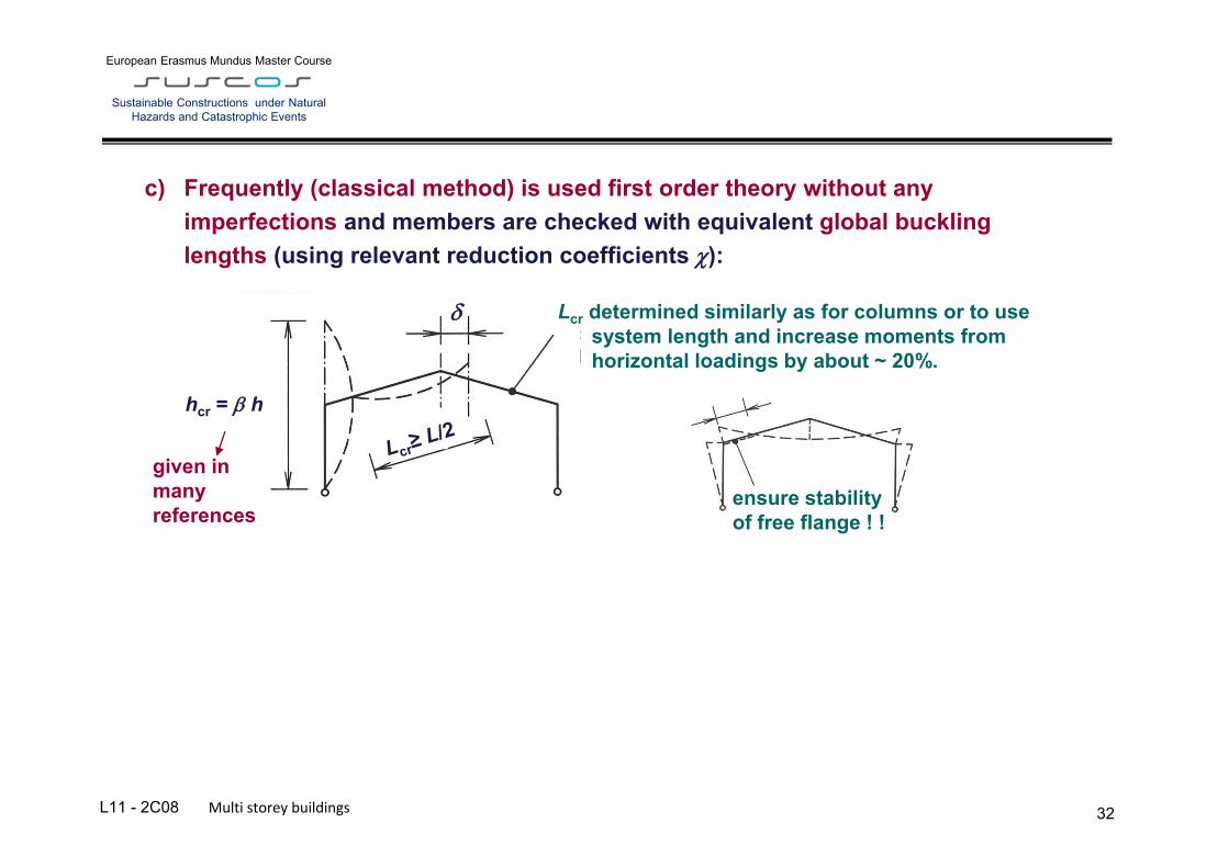
c) Frequently (classical method) is used first order theory without any imperfections and members are checked with equivalent global buckling lengths (using relevant reduction coefficients ):
hcr = h
Lcr determined similarly as for columns or to use system length and increase moments from horizontal loadings by about ~ 20%.
ensure stability of free flange ! !
given in many references

L10 – B.2 – Mechanical properties of cast iron, mild iron and steel at historical structures
European Erasmus Mundus Master Course
Sustainable Constructions under Natural Hazards and Catastrophic Events
L11 - 2C08 Multi storey buildings 33
Typical global buckling lengths (for sway buckling mode):
Global buckling lengths are given in tables or formulas in literature. They may be preferably determined from critical loading Ncr by common software of corresponding cr (corresponding to buckled member) as follows:
Edcr
2
cr
2
cr NIE
NIEL
Note: 1) Using cr from approximate formula (i.e. for sway buckling mode), the minimum buckling length equals the system length. 1) Mind the modification of cross sections after check: results in different cr and hence also Lcr.
For symmetrical loading
for Irafter = ∞
for Irafter = ∞

L10 – B.2 – Mechanical properties of cast iron, mild iron and steel at historical structures
European Erasmus Mundus Master Course
Sustainable Constructions under Natural Hazards and Catastrophic Events
L11 - 2C08 Multi storey buildings 34
Global analysis - summary of possible approaches according to EN 1993-1-1
Global analysis
Design checks
Account for 2nd order
P-∆ effects
1st order analysis
cr < 10
cr > 10
Sway Mode Buckling Length
Amplified Sway Moment Method
(cr 3)
2nd order analysis
Amplified swaymoments
No limitation
Cross-section resistance and local stability
Joint resistance
Out-of-plane stability of the members
In plane member stability with system (non sway) buckling length equivalent b. length
1st order analysis
If GMNIA is used (both sway and member imperfections, no stability check (usually just in-plane) is necessary.
L10 – B.2 – Mechanical properties of cast iron, mild iron and steel at historical structures
European Erasmus Mundus Master Course
Sustainable Constructions under Natural Hazards and Catastrophic Events
L11 - 2C08 Multi storey buildings 35
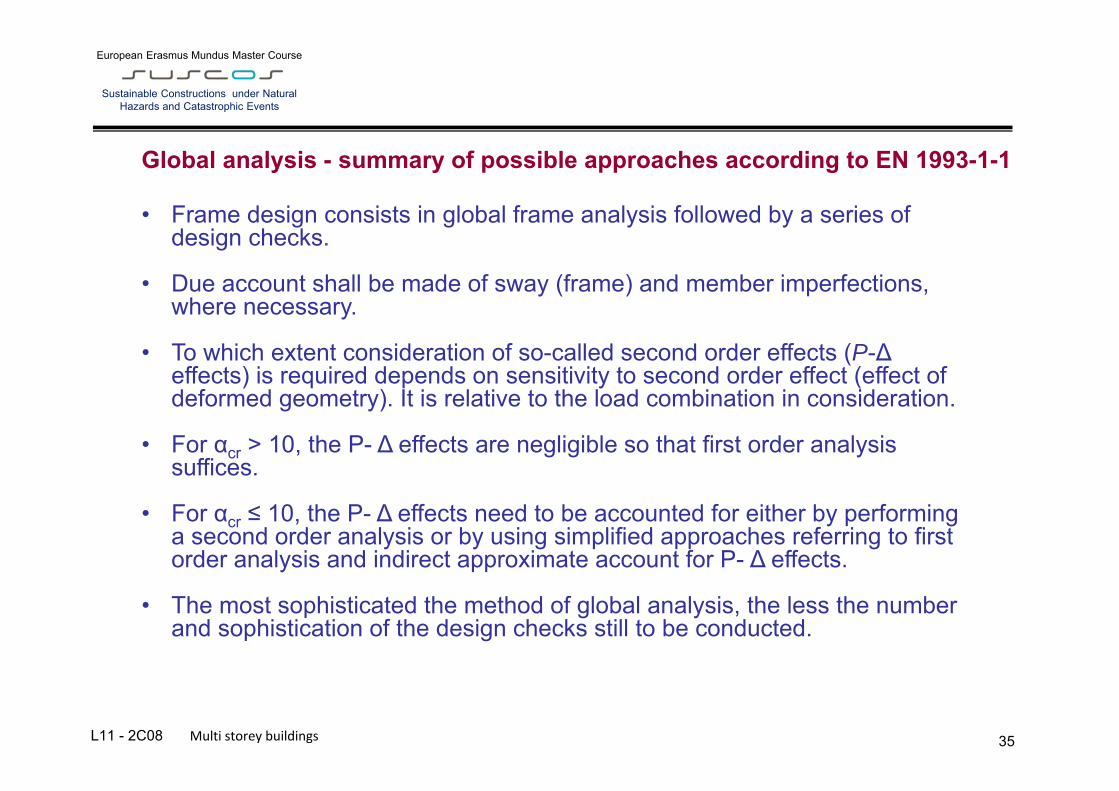
Global analysis - summary of possible approaches according to EN 1993-1-1
• Frame design consists in global frame analysis followed by a series of design checks.
• Due account shall be made of sway (frame) and member imperfections, where necessary.
• To which extent consideration of so-called second order effects (P-∆ effects) is required depends on sensitivity to second order effect (effect of deformed geometry). It is relative to the load combination in consideration.
• For αcr > 10, the P- ∆ effects are negligible so that first order analysis suffices.
• For αcr ≤ 10, the P- ∆ effects need to be accounted for either by performing a second order analysis or by using simplified approaches referring to first order analysis and indirect approximate account for P- ∆ effects.
• The most sophisticated the method of global analysis, the less the number and sophistication of the design checks still to be conducted.
L10 – B.2 – Mechanical properties of cast iron, mild iron and steel at historical structures
European Erasmus Mundus Master Course
Sustainable Constructions under Natural Hazards and Catastrophic Events
L11 - 2C08 Multi storey buildings 36
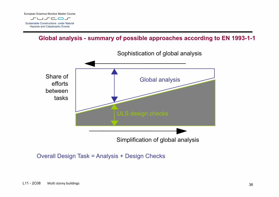
Global analysis - summary of possible approaches according to EN 1993-1-1
Share of efforts
between tasks
Simplification of global analysis
Sophistication of global analysis
Global analysis
ULS design checks
Overall Design Task = Analysis + Design Checks

L10 – B.2 – Mechanical properties of cast iron, mild iron and steel at historical structures
European Erasmus Mundus Master Course
Sustainable Constructions under Natural Hazards and Catastrophic Events
L11 - 2C08 Multi storey buildings 37
This lecture was prepared for the 1st Edition of SUSCOS (2012/14) by Prof. Josef Macháček (CTU) and Michal
Jandera, PhD. (CTU).
Adaptations brought by Florea Dinu, PhD (UPT) for 2nd Edition of SUSCOS
The SUSCOS powerpoints are covered by copyright and are for the exclusive use by the SUSCOS teachers in the framework of this Erasmus
Mundus Master. They may be improved by the various teachers throughout the different editions.