multiprogram/project common-use document
TRANSCRIPT

NOT MEASUREMENT SENSITIVE
MSFC-STD-3029 REVISION A
EFFECTIVE DATE: February 24, 2005 SUPERSEDES:
MSFC-STD-3029, BASELINE May 22, 2000
National Aeronautics and Space Administration George C. Marshall Space Flight Center Marshall Space Flight Center, Alabama 35812
EM30
MULTIPROGRAM/PROJECT
COMMON-USE DOCUMENT
GUIDELINES FOR THE SELECTION OF METALLIC MATERIALS FOR STRESS CORROSION CRACKING RESISTANCE IN SODIUM CHLORIDE ENVIRONMENTS
Materials and Processes Laboratory Metals Engineering Branch UNLIMITED DISTRIBUTION
CHECK THE MASTER LIST- VERIFY THAT THIS IS THE CORRECT VERSION BEFORE USE.
MSFC-FORM 454 (Rev. October 1992)

Multiprogram/Project Common-Use Document EM30
MSFC-STD-3029 Revision: A Guidelines for the Selection of Metallic Materials for Stress Corrosion Cracking Resistance in Sodium Chloride
Environments Date: February 24, 2005 Page 2 of 45
Check the master list. Verify that this is the correct version before use.
DOCUMENT HISTORY LOG Status (Baseline/ Revision/ Canceled)
Document Revision
Effective Date
Description
Baseline
May 22, 2000 This standard supersedes MSFC-SPEC-522B, which was issued in July 1, 1987.
Revision
A February 24, 2005
This version supersedes the baseline, which was published in May 22, 2000.

Multiprogram/Project Common-Use Document EM30
MSFC-STD-3029 Revision: A Guidelines for the Selection of Metallic Materials for Stress Corrosion Cracking Resistance in Sodium Chloride
Environments Date: February 24, 2005 Page 3 of 45
Check the master list. Verify that this is the correct version before use.
FOREWORD MSFC-STD-3029 evolved from MSFC-SPEC-522B ("Design Criteria for Controlling Stress Corrosion Cracking"), which was originated as a tool to control stress corrosion cracking throughout NASA programs. The purpose of this document is to provide guidelines to designers regarding materials selection for stress corrosion resistance and to present the requirements for the approval of materials with moderate or high susceptibility. In this revision of MSFC-STD-3029 the austenitic stainless steels CRES 303 and 303Se (free machining steels of the 300 series) have been removed from Table III. These alloys had been classified as highly susceptible to stress corrosion as a conservative approach to recommendations received during the NASA-wide review of the document. Additional testing indicated that these alloys are not susceptible to stress corrosion cracking in a sodium chloride environment at a neutral pH. Therefore, along with other stainless steels of the 300 series (in the unsensitized condition) they are classified as a group in Table I (highly resistant) in this version of the document. Request for information, corrections, or additions to this document shall be directed to The Materials and Processes Laboratory, Metals Engineering Branch, EM30, Marshall Space Flight Center, Huntsville, Al 35812. Pablo D. Torres Metallic Materials Engineering Team NASA MSFC Voice: 205-544-2616 Fax: 256-544-5877 [email protected]

Multiprogram/Project Common-Use Document EM30
MSFC-STD-3029 Revision: A Guidelines for the Selection of Metallic Materials for Stress Corrosion Cracking Resistance in Sodium Chloride
Environments Date: February 24, 2005 Page 4 of 45
Check the master list. Verify that this is the correct version before use.
TABLE OF CONTENTS PARAGRAPH
DOCUMENT HISTORY LOG............................................................................................................................................................ 2
FOREWORD...................................................................................................................................................................................... 3
TABLE OF CONTENTS..................................................................................................................................................................... 4
LIST OF FIGURES............................................................................................................................................................................. 6
LIST OF TABLES.............................................................................................................................................................................. 6
LIST OF APPENDICES..................................................................................................................................................................... 6
1. SCOPE........................................................................................................................................................................................... 7
1.1 PURPOSE.................................................................................................................................................................................. 7 1.2 APPLICABILITY........................................................................................................................................................................... 7
2. APPLICABLE DOCUMENTS....................................................................................................................................................... 7
2.1 GOVERNMENT DOCUMENTS...................................................................................................................................................... 7 2.2 AMERICAN SOCIETY FOR TESTING AND MATERIALS (ASTM) DOCUMENTS............................................................................. 7 2.3 ORDER OF PRECEDENCE. ....................................................................................................................................................... 8
3. DEFINITION.................................................................................................................................................................................... 8
3.1 STRESS CORROSION................................................................................................................................................................ 8
4. GENERAL REQUIREMENTS........................................................................................................................................................ 8
4.1 L IMITATIONS.............................................................................................................................................................................. 8 4.1.1 Temperature and Environment Limitations............................................................................................................. 8 4.1.2 Weldments..................................................................................................................................................................... 9 4.1.3 Specific Test Data......................................................................................................................................................... 9 4.1.4 Data Limitations............................................................................................................................................................ 9
4.2 GRAIN ORIENTATION. ............................................................................................................................................................... 9 4.2.1 Processing Operations. .............................................................................................................................................. 9
4.2.1.1 Rolling and Extruding. .......................................................................................................................................... 9 4.2.1.2 Forgings...............................................................................................................................................................10
4.2.2 Short Transverse Direction. ......................................................................................................................................10 4.3 STRESS CONSIDERATIONS. ....................................................................................................................................................10
4.3.1 Examples of Assembly Stresses. ...........................................................................................................................10 4.3.2 Examples of Residual Stresses..............................................................................................................................10
4.4 SUSCEPTIBILITY OF ENGINEERING ALLOYS...........................................................................................................................10 4.4.1 Aluminum Alloys. ........................................................................................................................................................10
4.4.1.1 Mechanical Stress Relief...................................................................................................................................11 4.4.1.2 Machining Wrought Aluminum. .......................................................................................................................11
4.4.2 Ferrous Alloys..............................................................................................................................................................11 4.4.3 Nickel Alloys.................................................................................................................................................................11 4.4.4 Copper Alloys. .............................................................................................................................................................11
PAGE

Multiprogram/Project Common-Use Document EM30
MSFC-STD-3029 Revision: A Guidelines for the Selection of Metallic Materials for Stress Corrosion Cracking Resistance in Sodium Chloride
Environments Date: February 24, 2005 Page 5 of 45
Check the master list. Verify that this is the correct version before use.
4.4.5 Titanium Alloys. ...........................................................................................................................................................11
5. DETAILED REQUIREMENTS.....................................................................................................................................................12
5.1 TESTING OF METALLIC MATERIALS FOR STRESS CORROSION SUSCEPTIBILITY....................................................................12 5.1.1 Test Specimens..........................................................................................................................................................12 5.1.2 Chemical Composition of the Test Materials........................................................................................................12 5.1.3 Hardness Tests. .........................................................................................................................................................12 5.1.4 Mechanical Properties of the Test Materials. ........................................................................................................12 5.1.5 Stressing and Exposure of Specimens to the Test Environment(s): ...............................................................13 5.1.6 Determination of Reduction in Load Carrying Ability. ..........................................................................................13 5.1.7 Test Environments. ....................................................................................................................................................13
5.1.7.1 Alternate Immersion in 3.5-Percent Sodium Chloride Solution per ASTM G44......................................13 5.1.7.2 Five-Percent Salt Spray Per ASTM B117.........................................................................................................13 5.1.7.3 High Humidity. .....................................................................................................................................................14 5.1.7.4 Seacoast Environment.......................................................................................................................................14 5.1.7.5 Slow Strain Rate per ASTM G129. ...................................................................................................................14 5.1.7.6 New Techniques For Stress Corrosion Testing. ..........................................................................................14
5.1.8 Test Duration. ..............................................................................................................................................................14 5.1.9 Verification of Stress Corrosion Failures. ..............................................................................................................15 5.1.10 Reporting of Results................................................................................................................................................15
5.2 RATING OF ALLOYS FOR STRESS CORROSION SUSCEPTIBILITY...........................................................................................15 5.2.1 Stress Corrosion Ratings Based on Alternate Immersion or Salt Spray Tests. ............................................15
5.2.1.1 Table I Requirements. .......................................................................................................................................15 5.2.1.2 Table II Requirements. ......................................................................................................................................15 5.2.1.3 Table III Requirements. .....................................................................................................................................16
5.2.2 Stress Corrosion Ratings Based on Less Conventional Tests........................................................................16 5.2.3 Stress Corrosion Ratings Based on Service Experience...................................................................................16 5.2.4 Criteria For Accepting Stress Corrosion Ratings Based On Data Obtained From Other Laboratories. .........................................................................................................................................................................16
5.3 USE OF STRESS CORROSION RATINGS IN DESIGN TO PREVENT FAILURES. .......................................................................16 5.3.1 Materials Selection Criteria.......................................................................................................................................16
5.3.1.1 Table I Alloys. .......................................................................................................................................................16 5.3.1.2 Table II Alloys. ......................................................................................................................................................17
5.3.1.2.1 High Installation Stresses. ........................................................................................................................17 5.3.1.2.2 Aluminum Alloy Sheet Material. ................................................................................................................17
5.3.1.3 Table III Alloys. .....................................................................................................................................................17 5.3.2 Request For Materials Approval Prior to Use, Assembly, or Integration. .........................................................17
5.4 ASSESSMENT OF THE POTENTIAL FOR A STRESS CORROSION FAILURE. .............................................................................17 5.5 THE MATERIALS USAGE AGREEMENT (MUA)..........................................................................................................................19 5.6 UNLISTED MATERIALS.............................................................................................................................................................20 5.7 PROTECTIVE COATINGS..........................................................................................................................................................20 5.8 SURFACE TREATMENTS. .........................................................................................................................................................20
6. NOTES.........................................................................................................................................................................................21
6.1 INTENDED USE........................................................................................................................................................................21 6.2 CAUTION AGAINST MISAPPLICATION OF THIS DOCUMENT.....................................................................................................21 6.3 KEYWORDS.............................................................................................................................................................................21

Multiprogram/Project Common-Use Document EM30
MSFC-STD-3029 Revision: A Guidelines for the Selection of Metallic Materials for Stress Corrosion Cracking Resistance in Sodium Chloride
Environments Date: February 24, 2005 Page 6 of 45
Check the master list. Verify that this is the correct version before use.
LIST OF FIGURES FIGURE TITLE PAGE
1. GRAIN ORIENTATION IN STANDARD WROUGHT FORMS. ..........................................................................................................22 2. EXAMPLES OF TENSILE STRESSES IN SHORT TRANSVERSE DIRECTION APPLIED DURING ASSEMBLY. ..................................23 3. EXAMPLES OF TENSILE STRESSES IN SHORT TRANSVERSE DIRECTION RESULTING FROM ASSEMBLY. .................................24 4. TYPICAL RESIDUAL STRESS DISTRIBUTION IN 7075 ALUMINUM ALLOY SHAPES....................................................................25 5. TYPICAL STRESS CORROSION ASSEMBLIES. ............................................................................................................................26 6. TYPICAL EQUIPMENT USED FOR STRESS CORROSION EVALUATIONS.....................................................................................27 7. TYPICAL SCANNING ELECTRON MICROSCOPE VIEWS OF A STRESS CORROSION CRACKING FAILURE.................................28 8. TYPICAL METALLOGRAPHIC VIEWS OF A STRESS CORROSION CRACKING FAILURE. .............................................................29
LIST OF TABLES TABLE I. ALLOYS WITH HIGH RESISTANCE TO STRESS CORROSION CRACKING IN SODIUM CHLORIDE ENVIRONMENTS I-A. FERROUS ALLOYS ......................................................................................................................................................30 I-B. ALUMINUM ALLOYS.....................................................................................................................................................31 I-C. COPPER ALLOYS ........................................................................................................................................................32 I-D. NICKEL ALLOYS...........................................................................................................................................................33 I-E. MISCELLANEOUS ALLOYS........................................................................................................................................34 TABLE II. ALLOYS WITH MODERATE RESISTANCE TO STRESS CORROSION CRACKING IN SODIUM CHLORIDE ENVIRONMENTS II-A. FERROUS ALLOYS .....................................................................................................................................................35 II-B. MAGNESIUM ALLOYS.................................................................................................................................................35 II-C. ALUMINUM ALLOYS....................................................................................................................................................36 TABLE III. ALLOYS WITH LOW RESISTANCE TO STRESS CORROSION CRACKING IN SODIUM CHLORIDE ENVIRONMENTS III-A. FERROUS ALLOYS ....................................................................................................................................................37 III-B. ALUMINUM ALLOYS...................................................................................................................................................38 III-C. COPPER ALLOYS ......................................................................................................................................................39 III-D. MAGNESIUM ALLOYS................................................................................................................................................39
LIST OF APPENDICES APPENDIX PAGE
APPENDIX A. Stress Corrosion References........................................................................................................................40 APPENDIX B. Concluding Material.........................................................................................................................................45

Multiprogram/Project Common-Use Document EM30
MSFC-STD-3029 Revision: A Guidelines for the Selection of Metallic Materials for Stress Corrosion Cracking Resistance in Sodium Chloride
Environments Date: February 24, 2005 Page 7 of 45
Check the master list. Verify that this is the correct version before use.
1. SCOPE 1.1 PURPOSE. This document defines the design criteria that shall be used for the selection of metallic materials in order to prevent failure due to stress corrosion cracking. 1.2 APPLICABILITY. The exposure environment is limited to alternate immersion in salt water, salt fog, seacoast, and slow strain rate in a salt solution. Alloys used for electrical wiring and other similar nonstructural electrical or electronic applications are exempt from the requirements of this document. 2. APPLICABLE DOCUMENTS 2.1 GOVERNMENT DOCUMENTS. 2.1.1 MSFC-STD-506, "Material and Process Control Standard" 2.1.2 MSFC-Form-551, "Materials Usage Agreement Form" 2.2 AMERICAN SOCIETY FOR TESTING AND MATERIALS (ASTM) DOCUMENTS. 2.2.1 ASTM B117, “Standard Practice For Operating Salt Spray (Fog) Apparatus” 2.2.2 ASTM G30, “Standard Practice For Making and Using U-Bend Stress Corrosion Test Specimens” 2.2.3 ASTM G38, “Standard Practice For Making and Using C-Ring Stress Corrosion Test Specimens” 2.2.4 ASTM G39, “Standard Practice For Preparation and Use of Bent-Beam Stress Corrosion Test Specimens” 2.2.5 ASTM G44, “Standard Practice For Evaluating Stress Corrosion Cracking Resistance of Metals and Alloys by Alternate Immersion in 3.5-Percent Sodium Chloride solution" 2.2.6 ASTM G47, “Standard Test Method For Determining Susceptibility to Stress Corrosion Cracking of 2XXX and 7XXX Aluminum Alloy Products” 2.2.7 ASTM G49, “Standard Practice For Preparation and Use of Direct Tension Stress Corrosion Test Specimens”

Multiprogram/Project Common-Use Document EM30
MSFC-STD-3029 Revision: A Guidelines for the Selection of Metallic Materials for Stress Corrosion Cracking Resistance in Sodium Chloride
Environments Date: February 24, 2005 Page 8 of 45
Check the master list. Verify that this is the correct version before use.
2.2.8 ASTM G58, “Standard Practice For Preparation of Stress Corrosion Test Specimens for Weldments” 2.2.9 ASTM G64, “Standard Classification of the Resistance to Stress Corrosion Cracking of Heat-Treatable Aluminum Alloys” 2.2.10 ASTM G129, "Standard Practice For Slow Strain Rate Testing to Evaluate the Susceptibility of Metallic Materials to Environmentally Assisted Cracking" 2.3 ORDER OF PRECEDENCE. In case of a conflict between the text of this document and the references cited herein, the text of this document takes precedence. The content of this document, however, does not supersede applicable laws and regulations unless a specific exemption has been obtained. The latest issue in effect of this document shall be used.
3. DEFINITION 3.1 STRESS CORROSION. Stress corrosion may be defined as the combined action of sustained tensile stress and corrosion to cause premature failure of a susceptible material. Certain metallic materials are more susceptible than others. If a susceptible material is placed in service in a corrosive environment under tension of sufficient magnitude, and the duration of service is sufficient to permit the initiation and growth of cracks, failures can occur at a stress lower than the material would normally be expected to withstand. The corrosive environment need not be severe in terms of general corrosive attack. Service failures due to stress corrosion are frequently encountered for which the surfaces of the failed parts are not visibly corroded in a general sense. If failure of a susceptible material in a corrosive environment is to be avoided, the total tensile stress (residual and applied) in service is to be maintained at a safe level. Comparative stress corrosion thresholds can be determined for metallic materials under certain controlled test conditions. It is recommended that estimates of the stress corrosion threshold for a specific service application be determined for each alloy and heat treatment using a test piece, stressing procedure, and corrosive environment that are appropriate for the intended service.
4. GENERAL REQUIREMENTS 4.1 LIMITATIONS. 4.1.1 Temperature and Environment Limitations. The stress corrosion susceptibility of the alloys included in this document was determined at ambient temperature by conducting stress corrosion tests or by service experience with fabricated hardware. The majority of the stress corrosion tests were performed by exposing specimens to either 3.5-percent alternate immersion per ASTM G44 or 5-percent salt spray per ASTM B117. In many occasions, parallel tests were performed in a

Multiprogram/Project Common-Use Document EM30
MSFC-STD-3029 Revision: A Guidelines for the Selection of Metallic Materials for Stress Corrosion Cracking Resistance in Sodium Chloride
Environments Date: February 24, 2005 Page 9 of 45
Check the master list. Verify that this is the correct version before use.
seacoast environment or in a high humidity cabinet. Some data generated with the slow strain rate technique also involved the use of a sodium chloride solution as the corroding agent. Use of the criteria established herein shall be limited to designs for service involving similar exposure conditions. It is recommended that the behavior of the listed metallic materials at elevated temperature, and/or in specific chemical environments other than those mentioned above, be ascertained by additional testing. 4.1.2 Weldments. Weldments present a special problem in designing for resistance to stress corrosion cracking. In addition to the susceptibility of the parent metals, it is also necessary to consider the filler metal and the microstructural effects of heat and deformation introduced by the welding operations and subsequent thermal treatments. Susceptibility data are not as extensive for weldments as for alloys in mill form because of the additional variables to be considered. Most of the design criteria for weldments in this document are limited to aluminum alloys, selected stainless steels in the 300 series, and other specific alloys listed in Table I. 4.1.3 Specific Test Data. This document is intended to provide general criteria to be used in designing for resistance to stress corrosion cracking. Specific test data and other detailed information are not included. However, a list of references is attached as Appendix A from which additional information can be obtained. 4.1.4 Data Limitations. This document does not purport to be all inclusive of factors and criteria necessary for the total control of stress corrosion cracking in alloys. Data on stress corrosion susceptibility may be insufficient for many applications involving unfamiliar materials or unusual combinations of materials and environments. To ensure adequate stress corrosion resistance in these situations, it is necessary to conduct a detailed evaluation of susceptibility. Testing may also be necessary in those cases. 4.2 GRAIN ORIENTATION. 4.2.1 Processing Operations. Rolling, extruding, and forging are the most common processing operations employed in the production of standard wrought forms of metal. All produce a flow of metal in a predominant direction so that, microscopically, the metal is no longer isotropic. As a result, the properties of the metal vary according to the direction in which they are measured. The extent of directional variation depends on the property of interest. For susceptibility to stress corrosion cracking, the directional variation can be appreciable and is considered in the design of fabricated hardware. 4.2.1.1 Rolling and Extruding. The anisotropy of grain orientation produced by rolling and extruding is illustrated schematically in Figure 1. Taking the rolled plate as an example, it is conventional to describe grain orientation in three directions. The direction of rolling is the longitudinal direction, the direction perpendicular to the longitudinal and in the plane of the plate is the

Multiprogram/Project Common-Use Document EM30
MSFC-STD-3029 Revision: A Guidelines for the Selection of Metallic Materials for Stress Corrosion Cracking Resistance in Sodium Chloride
Environments Date: February 24, 2005 Page 10 of 45
Check the master list. Verify that this is the correct version before use.
long transverse direction, and the direction through the thickness of the plate is the short transverse direction. For certain shapes, the simple rules may not apply and grain orientation can only be established by experience with the shape and knowledge of the forming methods. As an example, consider the thick tee section illustrated in Figure 2. 4.2.1.2 Forgings. Identifying the short transverse direction of forgings also requires consideration. In a forging operation, the flow of metal is influenced and constrained by the shape of the die cavity. For complex shapes, there may be several regions where a short transverse direction exists. The direction perpendicular to the parting plane of the dies is always short transverse as illustrated in Figure 3. 4.2.2 Short Transverse Direction. The stress corrosion resistance of metals, especially aluminum alloys, is lower in the long transverse direction than it is in the longitudinal direction, however, it is worst in the short transverse direction. Figures 2 and 3 illustrate undesirable situations in which tensile stresses due to assembly have been applied in the short transverse direction. Similar situations shall be avoided for optimum resistance to stress corrosion cracking. 4.3 STRESS CONSIDERATIONS. In designing for stress corrosion resistance it is important to realize that stresses are additive and threshold stresses for susceptibility are often low. All possible sources of stress shall be considered to ensure that the threshold stresses are not exceeded. Stresses resulting from operational, transportation, and storage loads are often anticipated during design. Assembly and residual stresses may not be anticipated, and in many cases have been the major contributors to stress corrosion failure. There have been stress corrosion failures where the design stresses were intermittent and of short duration, and a minor contributor to failure. 4.3.1 Examples of Assembly Stresses. Assembly stresses can result from improper tolerances during fit-up (Figures 2 and 3), overtorquing, press fits, high interference fasteners, and welding. 4.3.2 Examples of Residual Stresses. Residual stresses can result from welding, machining, forming, and heat treating operations. Figure 4 illustrates the distribution and relative magnitudes of stress resulting from conventional heat treating and forming operations 4.4 SUSCEPTIBILITY OF ENGINEERING ALLOYS. 4.4.1 Aluminum Alloys. Many aluminum alloys exhibit excellent resistance to stress corrosion cracking in all standard tempers. However, the high strength aluminum alloys, which are of primary interest in aerospace applications, are approached cautiously. Some of these alloys are resistant only in the longitudinal grain direction, and the resistance of others varies with the specific temper. Because metallurgical processing of aluminum alloys usually results in a

Multiprogram/Project Common-Use Document EM30
MSFC-STD-3029 Revision: A Guidelines for the Selection of Metallic Materials for Stress Corrosion Cracking Resistance in Sodium Chloride
Environments Date: February 24, 2005 Page 11 of 45
Check the master list. Verify that this is the correct version before use.
pronounced elongation of grains, the variation of susceptibility with grain orientation is more extensive than for other metals. 4.4.1.1 Mechanical Stress Relief. Conventional processing methods designed to optimize strength, such as rolling, forging, casting, and welding, can result in high residual stresses. These high residual stresses are usually greater in aluminum products than in wrought forms of other metals, especially in thick sections. It is for this reason that wrought, heat-treatable aluminum alloys shall be mechanically stress relieved (the TX5X or TX5XX temper designations) whenever possible. Mechanical stress relief is lost if the alloy is resolutioned, thus becoming significantly more susceptible to stress corrosion cracking. 4.4.1.2 Machining Wrought Aluminum. Both the residual stress distribution and the grain orientation shall be carefully considered in designing a part to be machined from wrought aluminum. Machining alters the stress distribution and it may also result in the exposure of a short transverse region on the surface of the finished part to be subjected to tension in service. Examples of exposure of a short transverse region on machined parts are illustrated in Figures 2 and 3. 4.4.2 Ferrous Alloys. Carbon and low alloy steels with ultimate tensile strengths below 1241 MPa (180 ksi) are generally resistant to stress corrosion cracking. Austenitic stainless steels of the 300 series are also generally resistant. The susceptibility of the martensitic stainless steels of the 400 series depends on composition and heat treatment. Precipitation hardening stainless steels vary in susceptibility from extremely high to extremely low depending on composition and heat treatment. The susceptibility of precipitation hardening stainless steels increases with decreasing heat treatment tempering temperatures. Ferritic and duplex stainless steels are not as resistant to stress corrosion cracking as are austenitic stainless steels. 4.4.3 Nickel Alloys. As a class, alloys with high nickel content are resistant to stress corrosion cracking. 4.4.4 Copper Alloys. Industrial atmospheres containing pollutants of sulfur dioxide, oxides of nitrogen, and ammonia are reported to cause stress corrosion cracking of some copper alloys. Chlorides present in marine atmospheres may also cause stress corrosion cracking, but to a lesser extent than the previously listed pollutants. Many copper alloys containing more than 20 percent zinc are susceptible to stress corrosion cracking, even in the presence of alloying additions which normally impart resistance to stress corrosion. 4.4.5 Titanium Alloys. As a class, titanium alloys are generally resistant to stress corrosion cracking.

Multiprogram/Project Common-Use Document EM30
MSFC-STD-3029 Revision: A Guidelines for the Selection of Metallic Materials for Stress Corrosion Cracking Resistance in Sodium Chloride
Environments Date: February 24, 2005 Page 12 of 45
Check the master list. Verify that this is the correct version before use.
5. DETAILED REQUIREMENTS 5.1 TESTING OF METALLIC MATERIALS FOR STRESS CORROSION SUSCEPTIBILITY. This section describes the specimens and testing methods for determining susceptibility to stress corrosion cracking in sodium chloride (NaCl) environments and high humidity. The alloys included in the tables of this document were evaluated in NaCl environments, especially in alternate immersion in a salt solution or in salt spray. Data obtained in a seacoast environment and in high humidity is considered complementary. Data obtained using the slow strain rate technique exclusively is so indicated in the tables. Newer testing techniques are also described in general, but no data derived from these methods have been included in this revision.
5.1.1 Test Specimens. The material to be evaluated is heat treated, if required, followed by fabrication of the specimens. The stress corrosion specimens are fabricated in such a way that at least the short transverse grain direction is evaluated, if that direction can be identified (as in plate material). In the case of bar materials the specimens are fabricated in at least the transverse direction. The longitudinal and long-transverse directions have been evaluated for many alloys presented in this document for comparison purposes. There are several specimen configurations (Figure 5), however, the most commonly used to generate the data for the alloys presented in this document (Tables I, II, and III) is the 0.318-cm (0.125-in) gage length diameter round tensile specimen (Figure 5(a)), which is in accordance with ASTM G49. Other specimen configurations are: the C-ring (Figure 5(b)) in accordance with ASTM G38, the bent-beams (Figure 5(c)) in accordance with ASTM G39 (commonly used for testing welds and the flat tensile specimens for sheet materials), and the U-bend specimen (ASTM G30). The specimens are cleaned with solvents such as acetone and alcohol before exposure to the test environment. Other ASTM Practices that provide additional information on specimens and test methodology are ASTM G47, G64, and G58. 5.1.2 Chemical Composition of the Test Materials. A chemical analysis is recommended if the chemical composition is not supplied with the material or for verification. 5.1.3 Hardness Tests. This test is recommended since the susceptibility of metallic materials tends to increase with the hardness. 5.1.4 Mechanical Properties of the Test Materials. Tensile tests are performed, usually on three specimens, and averaged values for the 0.2-percent offset yield strength, ultimate tensile strength, percent of reduction in area and elongation, and modulus of elasticity (Young's modulus) are obtained. The susceptibility of metallic materials to stress corrosion tends to increase with the strength.

Multiprogram/Project Common-Use Document EM30
MSFC-STD-3029 Revision: A Guidelines for the Selection of Metallic Materials for Stress Corrosion Cracking Resistance in Sodium Chloride
Environments Date: February 24, 2005 Page 13 of 45
Check the master list. Verify that this is the correct version before use.
5.1.5 Stressing and Exposure of Specimens to the Test Environment(s). The specimens for the stress corrosion test are typically stressed in tension to 50, 75, and 90-percent of the yield strength. These values are obtained from stress-strain data. A device and fixtures for stressing round tensile specimens are presented in Figure 6(a). The strains corresponding to the desired stress levels are measure with an extensometer while the specimens are being loaded. After loading, the stressing frames are protected with a strippable coating to protect from corrosion and to prevent galvanic interaction between the specimen and frames. Three to five replicates are typically used, which are afterwards cleaned and exposed to the corrosive environment. Unstressed specimens are usually exposed simultaneously with the stressed specimens. These specimens are removed periodically (usually when failures of stressed specimens occur) or after completion of the test. C-rings and bent-beams are stressed by deflecting the specimen to calculated values corresponding to the desired stress levels. 5.1.6 Determination of Reduction in Load Carrying Ability. After exposure, any nonfailed stressed specimens are unloaded and along with the unstressed specimens are tensile tested to failure to determine reduction in load carrying ability. The effect of the corrosive environment alone is compared against the effect of both, the corrosive environment and the stress. The average load value of specimens obtained from the same material and tested in air (typically in triplicate) is used as control.
5.1.7 Test Environments. Alternate immersion in 3.5-percent NaCl and 5-percent salt spray are the most common environments used for stress corrosion evaluations. High humidity and seacoast exposure, which are less aggressive environments than the former two, have been used as complementary methods for several alloys. 5.1.7.1 Alternate Immersion in 3.5-Percent Sodium Chloride Solution per ASTM G44. This may be considered the preferred method for stress corrosion evaluations, especially for aluminum alloys and steels with low corrosion resistance. In this method the specimens are submerged in a 3.5-percent NaCl solution for 10 minutes and then removed from the solution for 50 minutes. This cycle is repeated for the entire duration of the test. During the test, the temperature of the air is maintained at 27 +/- 1oC (80 +/- 2oF), relative humidity at 45 +/- 10 percent, and pH at 6.8 +/- 0.4. A typical alternate immersion tester is illustrated in Figure 6(b). This tester consists of a Ferris wheel type mechanism containing six trays, in which the specimens are distributed. This mechanism rotates 60o every 10 minutes.
5.1.7.2 Five-Percent Salt Spray Per ASTM B117. This method tends to be more aggressive than alternate immersion. It has been used as a complementary test, especially for stainless steels. The apparatus (Figure 6(c)) consists of a chamber, an air saturator tower, a salt solution reservoir, an atomizing nozzle, specimens supports, a provision for chamber heating, a temperature controller, and two solution collectors. During the salt spray test, heated humidified air from the saturator tower is passed through the nozzle, and in the process draws up a five-percent salt solution that is sprayed at 35oC (95oF). The salt spray operates continuously, except for

Multiprogram/Project Common-Use Document EM30
MSFC-STD-3029 Revision: A Guidelines for the Selection of Metallic Materials for Stress Corrosion Cracking Resistance in Sodium Chloride
Environments Date: February 24, 2005 Page 14 of 45
Check the master list. Verify that this is the correct version before use.
the interruptions necessary to inspect the specimens and remove the collected solution inside the chamber. For every 80 cm2 (12.4 in2) of horizontal collecting area, one to two ml are collected per hour. The pH of this solution is maintained within the range of 6.5-7.2, and the salt concentration is 5 +/- 1 percent. 5.1.7.3 High Humidity. This environment is less aggressive than alternate immersion and salt spray and it is used as a complementary test. These tests are performed in a cabinet that maintains 97 +/- 3 percent humidity at 38 +/- 3oC (100 +/- 5oF) by bubbling up compressed air through deionized water.
5.1.7.4 Seacoast Environment. This method requires a longer test duration than the standard accelerated corrosion tests performed in a laboratory and is used as a complementary test. 5.1.7.5 Slow Strain Rate per ASTM G129. This procedure involves the application of a slow strain rate to a tensile specimen under controlled environmental conditions while monitoring load and extension of the specimen. The slow strain rate test always produces fracture of the test specimen. The degree of susceptibility is generally assessed through observation of difference in the behavior of the material in tests conducted in a corrosive environment (e.g., 3.5-percent NaCl) from that obtain from tests conducted in a control environment (e.g., air). Several measurable and quantifiable parameters can be chosen to indicate susceptibility to stress corrosion cracking by virtue of their ability to reflect loss in ductility, as the stress corrosion failures are associated with little plastic deformation during crack propagation. Parameters that can be chosen include the area under the load-elongation curve (fracture energy), elongation at fracture, time to failure, and percent of reduction in area. The lower the values are in a corrosive environment, in comparison to those determined in an inert environment (all other experimental conditions being the same), the more susceptible the material is to stress corrosion. 5.1.7.6 New Techniques For Stress Corrosion Testing. Two relatively new techniques for stress corrosion testing are the incremental loading technique and the constant load rating technique. These techniques involve either incremental or constant rate increases in the load applied to a precracked specimen, monitoring the crack-opening displacement response for indications of crack growth. Though these techniques are promising, at this writing, they have not been standardized and require interlaboratory verification. Data obtained from these methods can help making a more informed decision for the rating of an alloy.
5.1.8 Test Duration. The duration of a stress corrosion test may be influenced by the alloy resistance to corrosion, the specimen configuration, and the testing method. A typical stress corrosion test performed by using alternate immersion or salt spray environments has a duration of 90 days. Most of the specimens used are small, and when they are exposed to the test environment for long periods of time, failures can occur due to other mechanisms that are not necessarily stress corrosion (e.g., pitting corrosion, exfoliation, etc.). Significant

Multiprogram/Project Common-Use Document EM30
MSFC-STD-3029 Revision: A Guidelines for the Selection of Metallic Materials for Stress Corrosion Cracking Resistance in Sodium Chloride
Environments Date: February 24, 2005 Page 15 of 45
Check the master list. Verify that this is the correct version before use.
reduction of the cross sectional area of the specimens can induce overload failures. For this reason, the alloys are rated based on 30 days of exposure. 5.1.9 Verification of Stress Corrosion Failures. Scanning Electron Microscopy (SEM) and/or metallography are used for verification of stress corrosion failures. SEM and metallographic views of stress corrosion failures are presented in Figures 7 and 8. 5.1.10 Reporting of Results. A typical report includes, but is not limited to the following information: name of alloy manufacturer, heat or lot number, reference to applicable specification, chemistry, product form, thickness or diameter, process history, mechanical properties, modulus of elasticity, temper, test environment, type and dimensions of the specimens, applied stress, stress direction in relation to grain orientation, number of failures, days to failure, number of replicates, test duration, reduction in load carrying ability, and any deviations from standard procedures. If applicable, welding method or surface treatments applied are reported. Additional complementary information such as tables, illustrations (e.g., optical pictures, photomicrographs, etc.), or appendixes can be added as desired. 5.2 RATING OF ALLOYS FOR STRESS CORROSION SUSCEPTIBILITY. The alloys listed in this document were classified in three tables according to their relative susceptibility to stress corrosion cracking. These ratings are based on testing and experience, and apply only to the environments described in this section.
5.2.1 Stress Corrosion Ratings Based on Alternate Immersion or Salt Spray Tests. An alloy or weldment, at a specific strength level or temper, is added to Table I, II, or III of this document based on the performance of specimens fabricated in accordance with ASTM standard practices, stressed in the grain direction of maximum expected susceptibility (e.g., short transverse for plate and transverse for bar material), when feasible, and tested per ASTM G44 and/or B117.
5.2.1.1 Table I Requirements. Alloys, tempers, and weldments in Table I are considered highly resistant to stress corrosion cracking in 3.5-percent NaCl alternate immersion or 5-percent salt spray. An alloy or weldment can be added to this table if no stress corrosion failures occur on specimens stressed to 75-percent of the yield strength within 30 days of exposure.
5.2.1.2 Table II Requirements. Alloys, tempers, and weldments in Table II are considered moderately resistant to stress corrosion cracking in 3.5-percent NaCl alternate immersion or 5-percent salt spray. An alloy or weldment is added to this table if no stress corrosion failures occur on specimens stressed to 50-percent of the yield strength within 30 days of exposure.
5.2.1.3 Table III Requirements. Alloys, tempers, and weldments in Table III are considered to have low resistance to stress corrosion cracking in 3.5-percent NaCl alternate immersion or 5-percent salt spray.

Multiprogram/Project Common-Use Document EM30
MSFC-STD-3029 Revision: A Guidelines for the Selection of Metallic Materials for Stress Corrosion Cracking Resistance in Sodium Chloride
Environments Date: February 24, 2005 Page 16 of 45
Check the master list. Verify that this is the correct version before use.
They are placed in this table if stress corrosion failures occur on specimens stressed to 50-percent of the yield strength within 30 days of exposure. 5.2.2 Stress Corrosion Ratings Based on Less Conventional Tests. Ratings of alloys based on data obtained using less conventional testing methods (e.g., slow strain rate test) can be included provided a sodium chloride solution (usually 3.5-percent) was used as the corrosive environment and the method has demonstrated that can provide results that are in agreement with those obtained by standard methods. Verification tests using alternate immersion or salt spray tests are recommended. Ratings based exclusively on those data are so indicated in the tables. 5.2.3 Stress Corrosion Ratings Based on Service Experience. Ratings can also be based on the alloy history of stress corrosion failures. 5.2.4 Criteria For Accepting Stress Corrosion Ratings Based On Data Obtained From Other Laboratories. Data from other laboratories are accepted provided the specimens and test procedures comply with standard ASTM practices for stress corrosion tests in NaCl environments (see section 2.2 of this document) and a report is provided (see section 5.1.10). Accepted data for the rating of alloys are filed and included in the list of references for traceability purpose. It is recommended that laboratories interested in adding alloys to this document provide a set of specimens to be tested for verification of stress corrosion results and mechanical properties, material documentation described in section 5.1.10, and material for chemistry and hardness verification. 5.3 USE OF STRESS CORROSION RATINGS IN DESIGN TO PREVENT FAILURES. The ratings presented in this document shall serve as a guide to designers for the selection of metallic materials for stress corrosion resistance. Stress corrosion failures occur suddenly with no warning signs, and the results have been catastrophic. In order to avoid these failures, the designers shall select alloys and tempers with the highest possible stress corrosion ratings that still are suitable for the intended application. The environment(s) to which the structure is expected to be exposed (including assembly, transportation, storing, and in service environments) and the sustained tensile stresses derived from all sources (residual, assembly, and design stresses) shall be considered when making the material selection. 5.3.1 Materials Selection Criteria. This section is provided to emphasize the importance of materials selection to avoid failures due to stress corrosion. 5.3.1.1 Table I Alloys. Alloys, tempers, and weldments, which by testing and experience have shown high resistance to stress corrosion cracking (Table I) shall be used preferentially, and NASA approval is not required prior to use. All other alloys and weldments not listed in Table I, except as specifically exempted, shall be approved prior to use, assembly, or integration to a level where inspection or removal is prohibited. The procedure described in sections

Multiprogram/Project Common-Use Document EM30
MSFC-STD-3029 Revision: A Guidelines for the Selection of Metallic Materials for Stress Corrosion Cracking Resistance in Sodium Chloride
Environments Date: February 24, 2005 Page 17 of 45
Check the master list. Verify that this is the correct version before use.
5.4 and 5.5 shall be followed to request approval. The material shall be approved, when required, by the responsible materials and processes organization within NASA. 5.3.1.2 Table II Alloys. Alloys, tempers, and weldments that are moderately resistant to stress corrosion (Table II) can be considered for use only for cases where a suitable alloy with high resistance to stress corrosion cracking cannot be found. NASA approval is required before using any alloy or weldment from Table II.
5.3.1.2.1 High Installation Stresses. Materials from Table II shall not be proposed for use or approved in applications involving high installation stress, such as springs or fasteners.
5.3.1.2.2 Aluminum Alloy Sheet Material. Sheet material (less than 0.64 cm (0.25 inch) thick) of the aluminum alloys and conditions listed in Table II is considered resistant to stress corrosion and does not require NASA approval. 5.3.1.3 Table III Alloys. Alloys and tempers that are highly susceptible to stress corrosion cracking (Table III) can be considered for use only in applications where it can be demonstrated conclusively that the probability of stress corrosion is remote. The sustained tensile stress in critical grain directions, whatever its origin, is required to be significantly lower than the stress corrosion threshold of the metal, as obtained by laboratory testing per standard methods. Suitable protective measures shall be used and the environment shall not promote corrosion. Hardware fabricated from these materials shall be inspected regularly for corrosion and the potential for a stress corrosion failure shall be assessed at that time. The use of materials in Table III requires NASA approval prior to use, assembly, or integration. The rationale for the use of these materials shall be based on a detailed analysis of the potential for failure (see paragraphs 5.4 and 5.5). 5.3.2 Request For Materials Approval Prior to Use, Assembly, or Integration. Fabrication of structures first and requesting material approval later is not an acceptable practice, especially if stress corrosion was not considered a design factor. Table II and III alloys in such structures require NASA approval before the structure is put in service. If the material is rejected because of safety reasons or relatively high risk for a stress corrosion failure, corrective action shall be taken. 5.4 ASSESSMENT OF THE POTENTIAL FOR A STRESS CORROSION FAILURE. A complete assessment of the stress corrosion susceptibility as a potential for failure for the proposed or current use of a material from Table II or III shall be submitted to NASA. The following information shall be submitted for each application being evaluated: 5.4.1. Part Number 5.4.2 Part Name 5.4.3 Next Assembly Number

Multiprogram/Project Common-Use Document EM30
MSFC-STD-3029 Revision: A Guidelines for the Selection of Metallic Materials for Stress Corrosion Cracking Resistance in Sodium Chloride
Environments Date: February 24, 2005 Page 18 of 45
Check the master list. Verify that this is the correct version before use.
5.4.4 Manufacturer's Name, Address, and Phone Number 5.4.5 Material. The material shall be identified as specified on the drawing. Provide specific alloy and temper designation of raw material from which the part is to be fabricated. 5.4.6 Heat Treatment. List all thermal treatments that the part receives. 5.4.7 Size and Form. List the approximate dimensions of the raw material from which the part is to be fabricated. Include the raw material form (bar, plate, sheet, extrusion, forgings, etc.). 5.4.8 Sustained Tensile Stresses. Estimate all the sustained tensile stresses. Include the magnitude and the direction with respect to grain orientation. List the stresses according to their source (i.e., process residual, assembly, and design), and provide the basis on which the estimation was made. Note any special precautions to control stresses. 5.4.9 Special Processing. Note any processes used for reducing tensile stresses (such as shot peening or stress relief treatments). 5.4.10 Weldments. Provide a stress corrosion evaluation of all weldments and submit all information that may assist in that evaluation. For each weldment, list the alloy, form, and temper of the parent metal, filler alloy (if any), welding process, whether the weld bead was removed, and post weld thermal treatment or stress relief. 5.4.11 Environment. Include the expected corrosive environment to which the part may be exposed during its lifetime. This includes exposure during fabrication, assembly, and component storage as well as environmental conditions during use. Include length of exposure, temperature, pressure, and concentration. 5.4.12 Protective Finish. List any finishes which are applied for corrosion protection or which might affect the basic corrosion resistance of the component. 5.4.13 Function of Part. Provide the basic function of the part (or if more pertinent the assembly). 5.4.14 Effect of Failure. Provide the possible effect of failure of the part (or assembly) on all function or mission of the major assembly involved. Indicate whether the part or assembly is a fracture critical component (a part or assembly whose failure can lead to personal injury, loss of life, loss of a flight vehicle, hardware, ground structures, loss of property, etc.). 5.4.15 Evaluation of Stress Corrosion Susceptibility. Include the rationale on which the material selection was made and an explanation as to why no stress corrosion problems are expected.

Multiprogram/Project Common-Use Document EM30
MSFC-STD-3029 Revision: A Guidelines for the Selection of Metallic Materials for Stress Corrosion Cracking Resistance in Sodium Chloride
Environments Date: February 24, 2005 Page 19 of 45
Check the master list. Verify that this is the correct version before use.
5.4.16 Remarks. Include any additional information or explanatory notes not otherwise listed. 5.5 THE MATERIALS USAGE AGREEMENT (MUA). The MUA (MSFC-Form-551) is the means by which approval of a material shall be requested, if required. It consists of a gathering of information necessary to determine the acceptability of the material for stress corrosion resistance for the particular application(s). It serves as a method to promote the selection of stress corrosion resistant alloys. Similar usages of the same or similar alloys can be submitted on a single MUA. The MUA requires approval by the responsible materials and processes organization. The document that controls detailed processing, format (forms), and/or limitations prior to design usage and acceptance by the user/contractor is MSFC-STD-506. The MUA shall contain, but it is not limited to the following information: 5.5.1 Project 5.5.2 System 5.5.3 Subsystem 5.5.4 Originator 5.5.5 Originator's Organization, Address, and Phone Number 5.5.6 Identification of Part(s) 5.5.7 Drawings and Next Assembly Drawings 5.5.8 Item Description 5.5.9 Material Designation 5.5.10 Manufacturer 5.5.11 Specification 5.5.12 Proposed Effectivity/Serial Number 5.5.13 Material Description. Thickness, weight, and exposed area 5.5.14 Location on Spacecraft. Habitable or nonhabitable 5.5.15 Fracture Critical Component. Yes or no 5.5.16 Environment. Include pressure, temperature, and duration of exposure 5.5.17 Application

Multiprogram/Project Common-Use Document EM30
MSFC-STD-3029 Revision: A Guidelines for the Selection of Metallic Materials for Stress Corrosion Cracking Resistance in Sodium Chloride
Environments Date: February 24, 2005 Page 20 of 45
Check the master list. Verify that this is the correct version before use.
5.5.18 Rationale 5.6 UNLISTED MATERIALS. The stress corrosion resistance of alloys and weldments not listed in this document shall be ascertained by tests conducted in an environment representative of the proposed application or by a direct comparison with similar alloys and weldments for which susceptibility is known. In either case an MUA and a stress corrosion evaluation, or the equivalent, shall be submitted to NASA before the proposed alloy is used. If a test is to be conducted by the contractor, it is recommended that a copy of the test plan be provided to the appropriate NASA organization for concurrence. A typical test plan includes, but is not limited to the following information: a description of the material to be tested, the specimen configuration that is going to be used, equipment to be used to stress and expose specimens, applied stresses and direction in relation to grain orientation, number of replicates, the environment, temperature, pH, concentration of corrosive agent, the test duration, materials used for specimen holders, frames or racks, use of measuring devices (hygrothermographs, pH meters, etc.), techniques to be used to examine representative failures (if they occur), record keeping of material traceability (e.g., manufacturer, heat or lot numbers, chemical composition, reference to applicable specification, product form, process history, thermal treatment, mechanical properties, etc.), and proposed use of photographic documentation of the testing. A copy of the test results shall be attached to the MUA if the material is still considered for use for the proposed application after the test is complete. It is recommended that if the test is performed in a sodium chloride environment, a set of specimens be provided to NASA for verification of results and for possible incorporation of the alloy in this document. 5.7 PROTECTIVE COATINGS. Protective coatings do not change the stress corrosion rating of alloys to which they are applied. Though there are coatings that may delay the onset of stress corrosion, they may contain imperfections or their integrity may be degraded in service. Table II and III alloys thus treated shall be identified and a request for approval prior to their use, assembly, or integration shall be submitted to NASA through the MUA and stress corrosion evaluation method or the equivalent process. 5.8 SURFACE TREATMENTS. Surface treatments, such as carburizing or nitriding, which locally modify the compositional or thermal treatment, may adversely affect the stress corrosion rating of materials to which they are applied. All materials thus treated shall be identified and an MUA and stress corrosion evaluation forms, or the equivalent, shall be submitted to NASA for approval prior to their use.

Multiprogram/Project Common-Use Document EM30
MSFC-STD-3029 Revision: A Guidelines for the Selection of Metallic Materials for Stress Corrosion Cracking Resistance in Sodium Chloride
Environments Date: February 24, 2005 Page 21 of 45
Check the master list. Verify that this is the correct version before use.
6. NOTES 6.1 INTENDED USE. This document is intended to establish design requirements for the selection of metals used to fabricate space hardware and ground support equipment so that stress corrosion failures are prevented. 6.2 CAUTION AGAINST MISAPPLICATION OF THIS DOCUMENT. The ratings presented in this document apply only to the environments described. 6.3 KEYWORDS. Stress corrosion cracking, stress corrosion, stress corrosion ratings, alternate immersion, salt spray, salt fog, salt water, metals, materials, materials selection

Multiprogram/Project Common-Use Document EM30
MSFC-STD-3029 Revision: A Guidelines for the Selection of Metallic Materials for Stress Corrosion Cracking Resistance in Sodium Chloride
Environments Date: February 24, 2005 Page 22 of 45
Check the master list. Verify that this is the correct version before use.
FIGURE 1. GRAIN ORIENTATION IN STANDARD W ROUGHT FORMS.

Multiprogram/Project Common-Use Document EM30
MSFC-STD-3029 Revision: A Guidelines for the Selection of Metallic Materials for Stress Corrosion Cracking Resistance in Sodium Chloride
Environments Date: February 24, 2005 Page 23 of 45
Check the master list. Verify that this is the correct version before use.
FIGURE 2. EXAMPLES OF TENSILE STRESSES IN SHORT TRANSVERSE DIRECTION APPLIED DURING ASSEMBLY.

Multiprogram/Project Common-Use Document EM30
MSFC-STD-3029 Revision: A Guidelines for the Selection of Metallic Materials for Stress Corrosion Cracking Resistance in Sodium Chloride
Environments Date: February 24, 2005 Page 24 of 45
Check the master list. Verify that this is the correct version before use.
FIGURE 3. EXAMPLES OF TENSILE STRESSES IN SHORT TRANSVERSE DIRECTION RESULTING FROM ASSEMBLY.

Multiprogram/Project Common-Use Document EM30
MSFC-STD-3029 Revision: A Guidelines for the Selection of Metallic Materials for Stress Corrosion Cracking Resistance in Sodium Chloride
Environments Date: February 24, 2005 Page 25 of 45
Check the master list. Verify that this is the correct version before use.
FIGURE 4. TYPICAL RESIDUAL STRESS DISTRIBUTION IN 7075 ALUMINUM ALLOY SHAPES.

Multiprogram/Project Common-Use Document EM30
MSFC-STD-3029 Revision: A Guidelines for the Selection of Metallic Materials for Stress Corrosion Cracking Resistance in Sodium Chloride
Environments Date: February 24, 2005 Page 26 of 45
Check the master list. Verify that this is the correct version before use.
FIGURE 5. TYPICAL STRESS CORROSION ASSEMBLIES.
(a) Round Tensile Specimen and Stressing Frames
(b) C-Ring
(c) Bent-Beam Assembly

Multiprogram/Project Common-Use Document EM30
MSFC-STD-3029 Revision: A Guidelines for the Selection of Metallic Materials for Stress Corrosion Cracking Resistance in Sodium Chloride
Environments Date: February 24, 2005 Page 27 of 45
Check the master list. Verify that this is the correct version before use.
(a) Device and Frames Used to Stress Round Tensile Specimens
(b) Alternate Immersion Tester
(c) Salt Spray Cabinet
FIGURE 6. TYPICAL EQUIPMENT USED FOR STRESS CORROSION EVALUATIONS.

Multiprogram/Project Common-Use Document EM30
MSFC-STD-3029 Revision: A Guidelines for the Selection of Metallic Materials for Stress Corrosion Cracking Resistance in Sodium Chloride
Environments Date: February 24, 2005 Page 28 of 45
Check the master list. Verify that this is the correct version before use.
HP 9-4-30 W ELD
FIGURE 7. TYPICAL SCANNING ELECTRON MICROSCOPE V IEWS OF A STRESS CORROSION CRACKING FAILURE.

Multiprogram/Project Common-Use Document EM30
MSFC-STD-3029 Revision: A Guidelines for the Selection of Metallic Materials for Stress Corrosion Cracking Resistance in Sodium Chloride
Environments Date: February 24, 2005 Page 29 of 45
Check the master list. Verify that this is the correct version before use.
LONGITUDINAL MAG. 200X
TRANSVERSE MAG. 200X
MARAGING STEEL 200
FIGURE 8. TYPICAL METALLOGRAPHIC V IEWS OF A STRESS CORROSION CRACKING FAILURE.

Multiprogram/Project Common-Use Document EM30
MSFC-STD-3029 Revision: A Guidelines for the Selection of Metallic Materials for Stress Corrosion Cracking Resistance in Sodium Chloride
Environments Date: February 24, 2005 Page 30 of 45
Check the master list. Verify that this is the correct version before use.
TABLE I-A. FERROUS ALLOYS
W ITH HIGH RESISTANCE TO STRESS CORROSION CRACKING IN SODIUM CHLORIDE ENVIRONMENTS
UNS Number Alloy Condition G10900 (example) Carbon Steel, 1000 Series Below 1241 MPa (180 ksi) UTS G43400, K24728, etc. Low Alloy Steel (e.g., 4340, D6AC, 4130, etc.) Below 1241 MPa (180 ksi) UTS K08500 Music Wire Cold Drawn G10950 1095 Spring Steel Tempered K31820 HY-80 Steel Tempered Unknown HY-130 Steel Tempered Unknown HY-140 Steel Tempered Unknown ASP 11 Aged S20500 (example) 200 Series Stainless Steel (Unsensitized) All S31600 (example) 300 Series Stainless Steel (Unsensitized) (1) All S43000 (example 400 Series Ferritic Stainless Steel All S24100 Nitronic 32, also known as 18-2 Mn Annealed S24000 Nitronic 33 (2), also known as 18-3 Mn Annealed S21900 Nitronic 40, formerly 21-6-9(2) Annealed S21800 Nitronic 60 20 and 50 percent Cold Drawn S66286 A286 Stainless Steel All S35000 AM 350 Stainless Steel SCT 1000 (3) and Above S35500 AM 355 Stainless Steel SCT 1000 (3) and Above S36200 AM 362 (Almar 362) Stainless Steel 3 Hours At 538oC (1000oF) N08020 Carpenter 20Cb3 Stainless Steel All S45000 Custom 450 Stainless Steel H1000 (4) and Above S45500 Custom 455 Stainless Steel H1000 (4) and Above S15500 15-5 PH Stainless Steel H1000 (4) and Above S15700 PH 15-7 Mo Stainless Steel CH900 (5) S17700 17-7 PH Stainless Steel CH900 (5) K91472 HP9-4-20 All Unknown 904L Stainless Steel (6) Annealed N08367 AL-6XN (6) Annealed S31803 ES 2205 (6) Annealed S32950 7 Mo Plus (6) Annealed N08026 20 Mo-6 Annealed N08024 20 Mo-4 Annealed Notes: (1) Including weldments of 304L, 316L, 321, and 347. (2) Including weldments. (3) SCT 1000 = Sub-zero cooling and tempering at 538oC (1000oF). (4) H1000 = Hardened at 538oC (1000oF). (5) CH900 = Cold worked and aged at 482oC (900oC). (6) Evaluated with the Slow Strain Rate Technique. (7) UNS = Unified Numbering System Chemical composition of ferrous alloys listed in this table with unknown UNS numbers: HY-130: 0.12 C, 0.6-0.9 Mn, 4.75-5.25 Ni, 0.4-0.7 Cr, 0.3-0.65 Mo, 0.02 Ti, 0.05-0.10 V, 0.15 Cu, Bal Fe HY-140: 0-0.12 C, 0.6-0.9 Mn, 0.2-0.35 Si, 4.75-5.25 Ni, 0.4-0.7 Cr, 0.3-0.65 Mo, 0.05-0.1 V, 0.02 Ti, 0-0.15 Cu, Bal Fe ASP 11: 0-0.04 C, 0-0.8 Si, 0-1.5 Mn, 0-0.3 Cu, 5.3-6.9 Ni, 23.5-25 Cr, 1.45-1.95 Mo, 0.3-0.5 Nb, 0.001-0.003 B, Bal Fe 904L: 0.02 C max., 2 Mn max., 1 Si max., 0.03 P max., 0.015 S max., 19-23 Cr, 23-28 Ni, 4-5 Mo, 1-2 Cu

Multiprogram/Project Common-Use Document EM30
MSFC-STD-3029 Revision: A Guidelines for the Selection of Metallic Materials for Stress Corrosion Cracking Resistance in Sodium Chloride
Environments Date: February 24, 2005 Page 31 of 45
Check the master list. Verify that this is the correct version before use.
TABLE I-B. ALUMINUM ALLOYS W ITH HIGH RESISTANCE TO STRESS CORROSION CRACKING
IN SODIUM CHLORIDE ENVIRONMENTS Wrought Cast UNS Number Alloy (1) Temper (2) UNS Number Alloy Temper A91090 (example) 1000 Series All A03190, A13190 319.0, A319.0 As Cast A92011 2011 T8 A03330, A13330 333.0, A333.0 As Cast A92024 2024 Rod, Bar T8 A03550, A33550 355.0, C355.0 T6 A92219 2219 T6, T8 A03560, A13560 356.0, A356.0 All A92618 2618 T6 A03570 357.0 All A93002 (example) 3000 Series All A03580 358.0 (B358.0 or Tens-50) All A95005 (example) 5000 Series All (3), (4) A03590 359.0 All A96061 (example) 6000 Series All A03800, A13800 380.0, A380.0 As Cast A97049 7049 T73 A05140 514.0 formerly 214 As Cast (4) A97050 7050 T73 A05180 518.0 formerly 218 As Cast (4) A97075 7075 T73 A05350 535.0 formerly Almag 35 As Cast (4) A97149 7149 T73 A07100 710.0 formerly A712.0 As Cast A97475 7475 T73 A07110 711.0 formerly C712.0 As Cast Notes: (1) Including weldments of the weldable alloys. (2) Including mechanically stress relieved (TX5X or TX5XX) tempers when applicable. (3) High magnesium alloys 5456, 5053, and 5086 shall be used in controlled tempers (H111, H112, H116, H117, H323, H343) for resistance to stress corrosion cracking and exfoliation. (4) Alloys with magnesium content greater than 3.0 percent are not recommended for high temperature application, 66oC (150oF) and above.

Multiprogram/Project Common-Use Document EM30
MSFC-STD-3029 Revision: A Guidelines for the Selection of Metallic Materials for Stress Corrosion Cracking Resistance in Sodium Chloride
Environments Date: February 24, 2005 Page 32 of 45
Check the master list. Verify that this is the correct version before use.
TABLE I-C. COPPER ALLOYS
W ITH HIGH RESISTANCE TO STRESS CORROSION CRACKING IN SODIUM CHLORIDE ENVIRONMENTS
UNS Number
CDA (1) Number
Condition (Percent Cold Rolled) (2)
C11000 110 37 C17000 170 AT (3), HT (4) C17200 172 AT (3), HT (4) C19400 194 37 C19500 195 90 C23000 230 40 C28000 280 0 C42200 422 37 C44300 443 10 C51000 510 37 C52100 521 37 C52400 524 0 C60600 606 0 C61900 619 40 (9 percent B phase) C61900 619 40 (95percent B phase) C63800 638 0 C65500 655 0 C68800 688 40 C70400 704 0 C70600 706 50 C71000 710 0 C71500 715 0 C72500 725 40 C75200 752 50 Notes: (1) Copper Development Association. (2) Maximum percent cold rolled for which stress corrosion data is available. (3) AT - Annealed and precipitation hardened. (4) HT - Work hardened and precipitation hardened.

Multiprogram/Project Common-Use Document EM30
MSFC-STD-3029 Revision: A Guidelines for the Selection of Metallic Materials for Stress Corrosion Cracking Resistance in Sodium Chloride
Environments Date: February 24, 2005 Page 33 of 45
Check the master list. Verify that this is the correct version before use.
TABLE I-D. NICKEL ALLOYS
W ITH HIGH RESISTANCE TO STRESS CORROSION CRACKING IN SODIUM CHLORIDE ENVIRONMENTS
UNS Number Alloy Condition N14052 Glass Seal 52 CR (51Ni-49Fe) All K93601 Invar 36 (Including weldments(1)) All N10001 Hastelloy B Solution Heat Treated N10665 Hastelloy B2 (1) Annealed N10002 Hastelloy C All N06455 Hastelloy C-4 (1) Annealed N06022 Hastelloy C-22 (1) (Including weldments(1)) Annealed N10276 Hastelloy C-276 (1) (Including weldments(1)) Annealed N06030 Hastelloy G-30 (1) Annealed N06002 Hastelloy X All N08800 Incoloy 800 All N08825 Incoloy 825 All N09901 Incoloy 901 All N19903 Incoloy 903 All N06600 Inconel 600 (Including weldments) Annealed N06625 Inconel 625 Annealed N07718 Inconel 718 (Including weldments) All N07750 Inconel X750 All N05500 Monel K500 (Including weldments) All N09902 Ni-Span-C 902 All N07041 Rene 41 All unknown Unitemp 212 All N07001 Waspaloy All Not assigned NASA-23 All Notes: (1) Evaluated with the Slow Strain Rate Technique. Chemical composition of nickel alloys listed in this table with unknown UNS numbers: Unitemp 212: 25 Ni, 16 Cr, 4.1 Ti, 0.57 Cb, 0.06 C, 0.1 B, 0.07 Zr, Bal Fe NASA-23: 30 Ni, 14 Co, 9 Cr, 2.5 Nb, 2 Ti
Multiprogram/Project Common-Use Document EM30
MSFC-STD-3029 Revision: A Guidelines for the Selection of Metallic Materials for Stress Corrosion Cracking Resistance in Sodium Chloride
Environments Date: February 24, 2005 Page 34 of 45
Check the master list. Verify that this is the correct version before use.
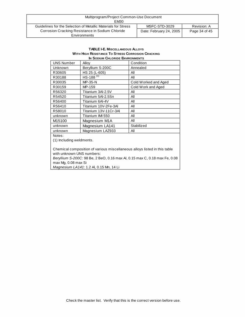
TABLE I-E. MISCELLANEOUS ALLOYS
W ITH HIGH RESISTANCE TO STRESS CORROSION CRACKING IN SODIUM CHLORIDE ENVIRONMENTS
UNS Number Alloy Condition Unknown Beryllium S-200C Annealed R30605 HS 25 (L-605) All R30188 HS-188 (1) All R30035 MP-35-N Cold Worked and Aged R30159 MP-159 Cold Work and Aged R56320 Titanium 3Al-2.5V All R54520 Titanium 5Al-2.5Sn All R56400 Titanium 6Al-4V All R56410 Titanium 10V-2Fe-3Al All R58010 Titanium 13V-11Cr-3Al All unknown Titanium IMI 550 All M15100 Magnesium M1A All unknown Magnesium LA141 Stabilized unknown Magnesium LAZ933 All Notes: (1) Including weldments. Chemical composition of various miscellaneous alloys listed in this table with unknown UNS numbers: Beryllium S-200C: 98 Be, 2 BeO, 0.16 max Al, 0.15 max C, 0.18 max Fe, 0.08 max Mg, 0.08 max Si Magnesium LA141: 1.2 Al, 0.15 Mn, 14 Li

Multiprogram/Project Common-Use Document EM30
MSFC-STD-3029 Revision: A Guidelines for the Selection of Metallic Materials for Stress Corrosion Cracking Resistance in Sodium Chloride
Environments Date: February 24, 2005 Page 35 of 45
Check the master list. Verify that this is the correct version before use.
TABLE II-A. FERROUS ALLOYS
W ITH MODERATE RESISTANCE TO STRESS CORROSION CRACKING IN SODIUM CHLORIDE ENVIRONMENTS
UNS Number Alloy Condition G10900 (example) Carbon Steel, 1000 Series 1241 to 1379 MPa (180 to 200 ksi) UTS G43400, K24728, etc. Low Alloy Steel (4340, D6AC, 4130, etc.) 1241 to 1379 MPa (180 to 200 ksi) UTS S21800 Nitronic 60 (1) Annealed S43000 (example) 400 Series Martensitic Stainless Steel, except 440C (2) S35000 AM350 Stainless Steel Below SCT 1000 S35500 AM355 Stainless Steel Below SCT 1000 S45000 Custom 450 Stainless Steel Below H1000 S45500 Custom 455 Stainless Steel Below H1000 S13800 PH 13-8 Mo Stainless Steel All S15500 15-5 PH Stainless Steel Below H1000 S17400 17-4 PH Stainless Steel (3) All K91283 HP 9-4-30 All Notes: (1) This alloy may be considered borderline between Table I and II. (2) Tempering between 371oC and 593oC (700oF and 1100oF) shall be avoided because corrosion and stress corrosion cracking resistance is lowered. (3) For better stress corrosion resistance tempering at 621oC (1150oF) is recommended.
TABLE II-B. MAGNESIUM ALLOYS W ITH MODERATE RESISTANCE TO STRESS CORROSION CRACKING
IN SODIUM CHLORIDE ENVIRONMENTS UNS Number Alloy Condition M11311 AZ31B All M16600 ZK60A All
Multiprogram/Project Common-Use Document EM30
MSFC-STD-3029 Revision: A Guidelines for the Selection of Metallic Materials for Stress Corrosion Cracking Resistance in Sodium Chloride
Environments Date: February 24, 2005 Page 36 of 45
Check the master list. Verify that this is the correct version before use.
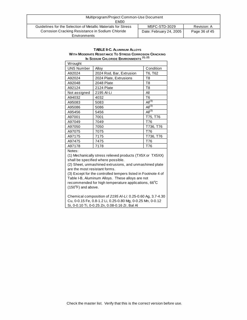
TABLE II-C. ALUMINUM ALLOYS W ITH MODERATE RESISTANCE TO STRESS CORROSION CRACKING
IN SODIUM CHLORIDE ENVIRONMENTS (1), (2)
Wrought UNS Number Alloy Condition A92024 2024 Rod, Bar, Extrusion T6, T62 A92024 2024 Plate, Extrusions T8 A92048 2048 Plate T8 A92124 2124 Plate T8 Not assigned 2195 Al-Li All A94032 4032 T6 A95083 5083 All(3) A95086 5086 All(3) A95456 5456 All(3) A97001 7001 T75, T76 A97049 7049 T76 A97050 7050 T736, T76 A97075 7075 T76 A97175 7175 T736, T76 A97475 7475 T76 A97178 7178 T76 Notes: (1) Mechanically stress relieved products (TX5X or TX5XX) shall be specified where possible. (2) Sheet, unmashined extrusions, and unmashined plate are the most resistant forms. (3) Except for the controlled tempers listed in Footnote 4 of Table I-B, Aluminum Alloys. These alloys are not recommended for high temperature applications, 66oC (150oF) and above. Chemical composition of 2195 Al-Li: 0.25-0.60 Ag, 3.7-4.30 Cu, 0-0.15 Fe, 0.8-1.2 Li, 0.25-0.80 Mg, 0-0.25 Mn, 0-0.12 Si, 0-0.10 Ti, 0-0.25 Zn, 0.08-0.16 Zr, Bal Al

Multiprogram/Project Common-Use Document EM30
MSFC-STD-3029 Revision: A Guidelines for the Selection of Metallic Materials for Stress Corrosion Cracking Resistance in Sodium Chloride
Environments Date: February 24, 2005 Page 37 of 45
Check the master list. Verify that this is the correct version before use.
TABLE III-A. FERROUS ALLOYS
W ITH LOW RESISTANCE TO STRESS CORROSION CRACKING IN SODIUM CHLORIDE ENVIRONMENTS
UNS Number Alloy Condition G10900 (example) Carbon Steel, 1000 Series Above 1379 MPa (200 ksi) UTS G43400, K24728, etc. Low Alloy Steel (4340, D6AC, 4130, etc.) Above 1379 MPa (200 ksi) UTS T20811 H-11 Tool Steel Above 1379 MPa (200 ksi) UTS S44004 440C Stainless Steel All K92810 18 Ni Maraging Steel (1), 200 Grade Aged at 482oC (900oF) K92890 18 Ni Maraging Steel, 250 Grade Aged at 482oC (900oF) K93120 18 Ni Maraging Steel, 300 Grade Aged at 482oC (900oF) unknown 18 Ni Maraging Steel, 350 Grade Aged at 482oC (900oF) S15700 PH 15-7Mo Stainless Steel All except CH900 S17700 17-7 PH Stainless Steel All except CH900 H93100 AISI 9310 Carburized K88165 M-50 NIL Carburized unknown CRB-7 Stainless Steel All K91283 (weldments) HP9-4-30 Weldments All K92580 AerMet 100 H875 and H900 S32550 Ferrallium 255 (2) Annealed Notes: (1) Carpenter NiMark Chemical composition of ferrous alloys listed in this table with unknown UNS numbers: 18 Ni Maraging Steel, 350 Grade: per MIL-S-46850 CRB-7 Stainless Steel: 1.1 C, 0.40 Mn, 0.3 Si, 14 Cr, 2 Mo, 1 V, 0.25 Cb

Multiprogram/Project Common-Use Document EM30
MSFC-STD-3029 Revision: A Guidelines for the Selection of Metallic Materials for Stress Corrosion Cracking Resistance in Sodium Chloride
Environments Date: February 24, 2005 Page 38 of 45
Check the master list. Verify that this is the correct version before use.
TABLE III-B. ALUMINUM ALLOYS
W ITH LOW RESISTANCE TO STRESS CORROSION CRACKING IN SODIUM CHLORIDE ENVIRONMENTS
(1), (2) Wrought Cast UNS Number Alloy Condition UNS Number Alloy Condition A92011 2011 T3, T4 A02950 295.0 (195) T6 A92014 2014 All A02960 296.0 formerly B295.0 or B195 T6 A92017 2017 All A05200 520.0 (220) T4 A92024 2024 T3, T4 A07070 707.0 (607, Ternalloy 7) T6 A92024 2024 Forgings T6, T62, T8 A07120 712.0 formerly D712.0, D612, or 40E As Cast A92024 2024 Plate T62 A92090 Al-Li 2090 T8E41 A92219 2219 T3, T4 unknown BS L93 T6 A97001 7001 T6 A97005 7005 All A97039 7039 All A97075 7075 T6 A97175 7175 T6 A97079 7079 T6 A97178 7178 T6 A97475 7475 T6 Notes: (1) Mechanically stress relieved products (TX5X or TX5XX) shall be specified where possible. (2) Sheet, unmashined extrusions, and unmachined plate are the least susceptible forms.

Multiprogram/Project Common-Use Document EM30
MSFC-STD-3029 Revision: A Guidelines for the Selection of Metallic Materials for Stress Corrosion Cracking Resistance in Sodium Chloride
Environments Date: February 24, 2005 Page 39 of 45
Check the master list. Verify that this is the correct version before use.
TABLE III-C. COPPER ALLOYS
W ITH LOW RESISTANCE TO STRESS CORROSION CRACKING IN SODIUM CHLORIDE ENVIRONMENTS
UNS Number
CDA (1) Number
Condition (2) percent Cold Rolled
C26000 260 50 C35300 353 50 C44300 443 40 C67200 672 50, Annealed C68700 687 10, 40 C76200 762 A, 25, 50 C76600 766 38 C77000 770 38, 50, Annealed C78200 782 50 Notes: (1) Copper Development Association. (2) Ratings based on listed conditions only.
TABLE III-D. MAGNESIUM ALLOYS W ITH LOW RESISTANCE TO STRESS CORROSION CRACKING
IN SODIUM CHLORIDE ENVIRONMENTS UNS Number Alloy Condition M11610 AZ61A All M11800 AZ80A All

Multiprogram/Project Common-Use Document EM30
MSFC-STD-3029 Revision: A Guidelines for the Selection of Metallic Materials for Stress Corrosion Cracking Resistance in Sodium Chloride
Environments Date: February 24, 2005 Page 40 of 45
Check the master list. Verify that this is the correct version before use.
APPENDIX A. Stress Corrosion References
File Number Reference 1950-03-00 Logan, H. L., and Hessing, H., “Stress Corrosion of Wrought Magnesium Base Alloys”, Part of
Journal of Research of the National Bureau of Standards Research Paper RP 2074, Volume 44, March 1950.
1955-08-00 Bloom, F. K., “Stress Corrosion Cracking of Hardenable Stainless Steels”, Armco Research Laboratories, Corrosion, Volume II, August 1955.
1961-08-00 “Stress Corrosion Cracking of High Strength Alloys”, Aerojet General Corp., Report Number DA-04-495-ORD-3069, August 1961.
1961-10-00 Kaltenhauser, R. H., “Stress Corrosion Resistance of AM-350”, Allegheny Ludlum Steel Corp., Report Number SS-450, October 1961.
1962-00-00 Sprowls, D. O., and Brown, R. H., “Resistance of Wrought High Strength Aluminum Alloys to Stress Corrosion”, Technical Paper Number 17, Aluminum Company of America, 1962.
1962-03-19 Rutemiller, H. C., and Sprowls, D. O., “Stress Corrosion of Aluminum-Where to Look for it, How to Prevent it”, Paper presented at 18th Conference and Corrosion Show of The National Association of Corrosion Engineers, March 19-23, 1962.
1962-08-01 Spuhler, C. H., and Burton, C. L., “Avoiding Stress Corrosion Cracking in High Strength Aluminum Alloy Structures”, Aluminum Company of America, August 1, 1962.
1963-06-24 Humphries, T. S., “Stress Corrosion of High-Strength Aluminum Alloys”, NASA, MSFC Technical Paper MTP-P&VE-M-63-8, June 24, 1963.
1964-03-00 “Chloride Stress Corrosion Susceptibility of High Strength Stainless Steel Titanium Alloy and Superalloy Sheet”, Douglas Aircraft Co., Request Number ML-TDR-64-44, Volumes I and II, March and May 1964.
1964-05-00 “An Evaluation of High Strength Steel Forgings”, General Dynamics, Report Number RTD TDR-63-4050, May 1964.
1965-06-11 Loginow, A. W., “Stress Corrosion Cracking of Austenitic Stainless Steel in Marine Environment”, U. S. Steel Corp., Unpublished Memorandum, June 11, 1965.
1965-08-09 Williamson, J. G, “Stress Corrosion Studies of AM-355 Stainless Steel”, NASA TMX-53317, August 9, 1965.
1966-00-00 Logan, H. L., “The Stress Corrosion of Metals”, John Wiley and Sons, Inc., New York, 1966. 1966-06-29 Humphries, T. S., “Procedure For Externally Loading and Corrosion Testing Stress Corrosion
Specimens”, NASA TMX-53483, June 29, 1966. 1967-00-00 Bond, A. P., Marshall, J. D., and Dundas, H. J., “Resistance of Ferritic Stainless Steels to Stress
Corrosion Cracking”, Published in ASTM STP 425 ("Stress Corrosion Testing"), American Society For Testing and Materials, 1967.
1967-03-18 “Stress corrosion Cracking in Aircraft Structural Materials”, AGARD Conference Proceedings Series Number 18, April 18 and 19, 1967.
1968-03-00 Reinhart, F. M., “Corrosion of Materials in Hydrospace”, Part IV-Copper and Copper Alloys, Naval Civil Engineering Laboratory, Technical Note N-961, April 1968.
1968-09-00 Leckie, H. P., and Loginow, A. W., “Stress Corrosion Behavior of High Strength Steels”, U. S. Steel Corp., Corrosion, Volume 24, Number 9, September 1968.
1969-09-12 Humphries, T. S., and Nelson, E. E., “Stress Corrosion Cracking Evaluation of Several Precipitation Hardening Stainless Steels”, NASA TMX-53910, September 12, 1969.
1969-11-19 Williamson, James G., “Stress Corrosion Cracking of Ti-6Al-4V Titanium Alloy in Various Fluids, NASA TMX-53971, November 19, 1969.
1970-04-02 Humphries, T. S. and Nelson, E. E., “Stress Corrosion Cracking Evaluation of Several Ferrous and Nickel Alloys”, NASA TMX-64511, April 2, 1970.
1971-05-00 Carter, C. S., et al, “Stress Corrosion Properties of High Strength Hardening Stainless Steels”, Corrosion, Volume 27, Number 5, May 1971.
1971-11-11 Nelson, E. E., “Stress Corrosion Cracking of Several High Strength Ferrous and Nickel Alloys”, NASA TMX-64626, November 11, 1971.

Multiprogram/Project Common-Use Document EM30
MSFC-STD-3029 Revision: A Guidelines for the Selection of Metallic Materials for Stress Corrosion Cracking Resistance in Sodium Chloride
Environments Date: February 24, 2005 Page 41 of 45
Check the master list. Verify that this is the correct version before use.
1973-05-00 Staley, J. T., “Comparison of Aluminum Alloys 7050, 7049, MA52, and 7175-T736 Die Forging”, Alcoa Laboratories, AFML-TR-73-34, May 1973.
1974-04-00 Humphries, T. S. and Nelson, E. E., “Stress Corrosion Cracking Susceptibility of 18 Ni Maraging Steel”, NASA TMX-64837, April 1974.
1975-08-00 Popplewell, J. M., and Gearing, T. V., “Stress Corrosion Resistance of Some Copper Base Alloys in Natural Atmospheres”, Olin Metals Research Laboratories, Corrosion, Volume 31, Number 8, August 1975.
1975-09-00 Sedricks, A. J., “Comparative Stress Corrosion Cracking Behavior of Austenitic Iron Base and Nickel Base Alloys”, Corrosion, Volume 31, Number 9, September 1975.
1976-06-00 Montano, J. W., “The Stress Corrosion Resistance and the Cryogenic Temperature Mechanical Behavior of 18-3 Mn (Nitronic 33) Stainless Steel Parent and Welded Material”, NASA TMX –73309, June 1976.
1977-01-00 Montano, J. W., “The Stress Corrosion Resistance and the Cryogenic Temperature Mechanical Properties of Hot Rolled Nitronic 60 Bar Material”, NASA TMX-73359, January 1977.
1977-04-00 Montano, J. W., “The Stress Corrosion Resistance and the Cryogenic Temperature Mechanical Properties of Annealed Nitronic 32 Bar Material”, NASA TMX-73375, April 1977.
1980-01-00 Humphries, T. S., “Stress Corrosion Cracking of Martensitic Precipitation Hardening Stainless Steel”, NASA TMX-78257, January 1980.
1980-01-24 Nelson, E. E., and Humphries, T. S., "Stress Corrosion Evaluation of AF1410 Alloy Steel", NASA, MSFC Memorandum EH24 (80-1), January 24, 1980.
1980-03-14 Nelson, E. E., and Humphries, T. S., "Stress Corrosion Resistance Evaluation of Resolution Heat Treated PH 13-8 Mo Stainless Steel", NASA, MSFC Memorandum EH24 (80-5), March 14, 1980.
1980-03-19 Humphries, T. S., and Nelson, E. E., "SCC Evaluation of Aluminum Alloy 2618-T651", NASA, MSFC Memorandum EH24 (80-6), March 19, 1980.
1980-04-02 Nelson, E. E., and Humphries, T. S., "Stress Corrosion Evaluation of Cast Ti-6Al-4V", NASA, MSFC Memorandum EH24 (80-11), April 2, 1980.
1980-05-00 Humphries, T. S., and Nelson, E. E., "Evaluation of the Stress Corrosion Cracking Resistance of Several High Strength Low Alloy Steels", NASA TM-78276, May 1980.
1980-10-00 Munafo, P. M., "Sustained Stress Flaw Growth for D6AC Material in the Space Shuttle Solid Rocket Motor Case", NASA Technical Memorandum, MSFC, October 1980.
1980-11-26 Humphries, T. S., and Nelson, E. E., "SCC Evaluation of Several Stainless Steel Bearing Materials", NASA, MSFC Memorandum EH24 (80-36), November 26, 1980.
1981-01-00 Humphries, T. S., “Seacoast Stress Corrosion Cracking of Aluminum Alloys”, NASA TM-82393, January 1981.
1981-05-26 Nelson, E. E., "Stress Corrosion Evaluation of AF1410 Alloy Steel", NASA, MSFC Memorandum EH24 (81-16), May 26, 1981.
1981-07-29 Humphries, T. S., and Nelson, E. E., "Evaluation of SCC of 2117-T4 Rivets in the SRB Tunnel", NASA, MSFC Memorandum EH24 (81-25), July 29, 1981.
1981-09-22 Humphries, T. S., and Nelson, E. E., "SCC Evaluation of Alloy Steels Above 200 ksi", NASA, MSFC Memorandum EH24 (81-33), September 22, 1981.
1981-10-07 Humphries, T. S., and Nelson, E. E., "Effect of Specimen Diameter on the SCC of Aluminum Alloys", NASA, MSFC Memorandum EH24 (81-36), October 7, 1981.
1981-10-30 Nelson, E. E., Humphries, T. S., and Lowery, J. R., "Evaluation of 4340M Steel for Stress Corrosion and Hydrogen Embrittlement", NASA, MSFC Memorandum EH24 (81-39), October 30, 1981.
1981-11-00 Humphries, T. S., and Coston, J. E., "An Improved Stress Corrosion Test Medium for Aluminum Alloys", NASA, MSFC TM-82452, November 1981.
1981-11-24 Montano, J. W., "Stress Corrosion Studies of Bare 4330M Alloy Steel Exposed to a 5 Percent Salt Spray Environment", NASA, MSFC Memorandum EH22 (81-102), November 24, 1981.
1981-12-01 Nelson, E. E., and Humphries, T. S., "Stress Corrosion Evaluation of 4330M Alloy Steel", NASA, MSFC Memorandum EH24 (81-43), December 1, 1981.
1982-05-17 Humphries, T. S., "SCC of 17-7 PH-CH900 Wire in Salt Fog", NASA, MSFC Memorandum EH24 (82-19), May 17, 1982.

Multiprogram/Project Common-Use Document EM30
MSFC-STD-3029 Revision: A Guidelines for the Selection of Metallic Materials for Stress Corrosion Cracking Resistance in Sodium Chloride
Environments Date: February 24, 2005 Page 42 of 45
Check the master list. Verify that this is the correct version before use.
1982-10-05 Humphries, T. S., "Stress Corrosion Cracking of 440C Under Cyclic Humidity", NASA, MSFC Memorandum EH24 (82-29), October 5, 1982.
1982-10-05 Nelson, E. E., and Humphries, T. S., "Evaluation of Stress Corrosion Cracking Alloys Exposed to Seacoast Environment", NASA, MSFC Memorandum EH24 (82-28), October 5, 1982.
1982-12-03 Humphries, T. S., Spittler, C, and Nelson, E. E., "Effect of Elevated Temperature Aging on the SCC of Several Aluminum Rivet Materials", NASA, MSFC Memorandum EH24 (82-38), December 3, 1982.
1982-11-29 Humphries, T. S., and Nelson, E. E., "The SCC Evaluation of 7050-T73 and 7075-T73 Aluminum Forgings", NASA, MSFC Memorandum EH24 (82-36), November 29, 1982.
1982-12-15 Montano, J. W., "Testing of Seven 416 SS Threaded Connector Sleeves Modified to Standard “C”-Ring Configuration", NASA, MSFC Technical Note, December 15, 1982.
1983-04-01 Humphries, T. S., "Evaluation of Media for SCC Testing - A. A. - ASTM Joint Task Group", NASA, MSFC Memorandum EH24 (83-16), April 1, 1983.
1983-06-15 Humphries, T. S., "The SCC Evaluation of MP159 Alloy", NASA, MSFC Memorandum EH24 (83-28), June 15, 1983.
1983-06-16 Humphries, T. S., and Spittler, C. L., "Evaluation of the SCC Resistance of Titanium IMI 550", NASA, MSFC Memorandum EH24 (83-29), June 16, 1983.
1983-07-19 Montano, J. W., "Stress Corrosion Test of A-286 CRES BSM Igniter Adapter Bolts", NASA, MSFC Technical Note, July 19, 1983.
1983-07-21 Humphries, T. S., and Spittler, C. L., "The Effect of Solution Treatment Temperature on the SCC Susceptibility of Aluminum alloy 7075", NASA, MSFC Memorandum EH24 (83-35), July 21, 1983.
1984-10-10 Schwinghamer, R. J., "Evaluation of the SCC Resistance of Hastelloy B", NASA, MSFC Memorandum EH24 (84-26), October 10, 1984.
1985-01-15 Humphries, T. S., "Evaluation of the SCC Resistance of Nickel-Iron Alloys", NASA, MSFC Memorandum EH24 (85-01), January 15, 1985.
1985-04-30 Humphries, T. S., "Evaluation of the SCC Resistance of Hastelloy B", NASA, MSFC Memorandum EH24 (85-11), April 30, 1985.
1985-05-02 Humphries, T. S., "Evaluation of the SCC Resistance of Hastelloy B2", NASA, MSFC Memorandum EH24 (85-12), May 2, 1985.
1985-07-03 Humphries, T. S., "Evaluation of the SCC Resistance of Hastelloy B in Salt Fog", NASA, MSFC Memorandum EH24 (85-18), July 3, 1985.
1985-07-25 Montano, J. W., "Stress Corrosion Evaluation of Processed and Aged Inconel 718 Bar Material Purchased From Wyman Gordon", NASA, MSFC Memorandum EH22 (85-59), July 25, 1985.
1985-10-21 Humphries, T. S., "Evaluation of the SCC Resistance of Custom 450 and 455 Stainless Steels", NASA, MSFC Memorandum EH24 (85-33), October 21, 1985.
1986-02-00 Montano, J. W., "A Torque, Tension, and Stress Corrosion Evaluation of High Strength A286 Bolts", NASA TM-86539, February 1986.
1986-02-03 Humphries, T. S., "Evaluation of the SCC Resistance of Aluminum-Lithium Alloy 2090-T8E41", NASA, MSFC Memorandum EH24 (86-01), February 3, 1986.
1986-02-19 Humphries, T. S., "Evaluation of the SCC Resistance of Hastelloy B", NASA, MSFC Memorandum EH24 (86-05), February 19, 1986.
1986-02-28 Humphries, T. S., "Evaluation of the SCC of Worked Strengthened and Aged Inconel 718", NASA, MSFC Memorandum EH24 (86-07), February 28, 1986.
1986-04-04 Humphries, T. S., "Evaluation of the SCC Resistance of Six Experimental Bearing Alloys", NASA, MSFC Memorandums EH24 (86-11), April 4, 1986 and EH24 (86-30), August 29, 1986.
1986-03-12 Humphries, T. S., "Evaluation of the SCC Resistance of Titanium Alloy Ti-10V-2Fe-3Al", NASA, MSFC Memorandum EH24 (86-08), March 12, 1986.
1986-09-00 Montano, J. W., "A Mechanical Property and Stress Corrosion Evaluation of VIM-ESR-VAR Work Strengthened and Direct Double Aged Inconel 718 Bar Material", NASA Technical Paper 2634, September 1986.
1986-09-15 Humphries, T. S., and McMillan, V. C., "Evaluation of the SCC Resistance of High Strength D6AC", NASA, MSFC Memorandum EH24 (86-33), September 15, 1986.

Multiprogram/Project Common-Use Document EM30
MSFC-STD-3029 Revision: A Guidelines for the Selection of Metallic Materials for Stress Corrosion Cracking Resistance in Sodium Chloride
Environments Date: February 24, 2005 Page 43 of 45
Check the master list. Verify that this is the correct version before use.
1986-10-00 Curtis, Leslie A., "Stress Corrosion Testing of 2024 Aluminum Alloy Using the Slow Strain-Rate Method", NASA, MSFC TM-86568, October 1986.
1987-01-23 Humphries, T. S., "Breaking Strength Data, 99 Percent Survival Stresses, and Statistical Threshold Stress Calculations for Assessing the SCC Resistance of 7075 Aluminum Alloy Products", NASA, MSFC Memorandum EH24 (87-03), January 23, 1987.
1987-03-11 Humphries, T. S., and McMillan, V. C., "Evaluation of the SCC of Custom 455 for the Inertial Upper Stage (IUS)", NASA, MSFC Memorandum EH24 (87-11), March 11, 1987.
1987-10-21 Humphries, T. S., "SCC of Welded Custom 455 for Control Moment Gyro Rotor Weld", NASA, MSFC Memorandum EH24 (87-33), October 21, 1987.
1987-10-29 Humphries, T. S., and Torres, P. D., "Investigation of Cracked SRB-BSM Case", NASA, MSFC Memorandum EH24 (87-34), October 29, 1987.
1988-06-27 Humphries, T. S., and Torres, P. D., "Evaluation of the SCC Resistance of Cobalt Free 18Ni Maraging T-250 Steel", NASA, MSFC Memorandum EH24 (88-13), June 27, 1988.
1988-08-04 Humphries, T. S., and Torres, P. D., "Evaluation of CBN Grinding Versus Normal Machining in the Fabrication of SRM Cases", NASA, MSFC Memorandum EH24 (88-17), August 4, 1988.
1988-09-19 Torres, P. D., "Evaluation of the SCC Resistance of Glass Sealing Alloys", NASA, MSFC Memorandum EH24 (88-19), September 19, 1988.
1988-09-23 Torres. P. D., "Stress Corrosion Test of D6AC", NASA, MSFC Memorandum EH24 (88-20), September 23, 1988.
1989-01-25 Torres, Pablo D., "Stress Corrosion Test of Aluminum Extrusion 2219", NASA, MSFC Memorandum EH24 (89-03), January 25, 1989.
1989-04-00 Goodyear, M., "Alcoa Alloy 2090", Alcoa Green Letter GL 226 (06-89), Aluminum Company of America, Alcoa Center, PA, April 1989.
1989-05-05 Torres, P. D., "Stress Corrosion Test of Inconel 625/Inconel 625 Nickel Plated Brazed Joints", NASA, MSFC Memorandum EH24 (89-12), May 5, 1989.
1989-07-00 Torres, Pablo D., "Stress Corrosion Study of PH 13-8 Mo Stainless Steel Using the Slow Strain Rate Technique", NASA Technical Paper 2934, July 1989.
1990-04-20 Munafo, P. M., "Completion of the Qualitative Evaluation of RSRM Pin Hole Residual Stresses on Stress Corrosion Cracking Susceptibility", NASA, MSFC Memorandum EH23 (90-74), April 20, 1990.
1990-05-25 Schwinghamer, R. J., "Completion of the Qualitative Evaluation of Redesigned Solid Rocket Motor (RSRM) Pin Hole Residual Stresses on Stress Corrosion Cracking Susceptibility", NASA, MSFC Memorandum EA01, May 25, 1990.
1991-02-19 Torres, P. D., "Summary of Memorandums Reporting Stress Corrosion Data on D6AC", NASA, MSFC Memorandum EH24 (91-16), February 19, 1991.
1991-05-13 Alcoa SCC Data on 2090 for Various Forms and Tempers, Alcoa Technical Center, May 13-October 10, 1991.
1991-09-00 Torres, P. D., "Stress Corrosion Study of Carburized AISI 9310 and Carburized M-50 NiL Steels", NASA Technical Paper 3148, September 1991.
1991-10-22 Torres, P. D., "Summaries of Stress Corrosion Tests", NASA, MSFC Memorandum EH24 (91-78), October 22, 1991.
1992-10-22 Torres, P. D., "MSFC Stress Corrosion Test Procedure Currently Followed for Testing Round Tensile Specimens", NASA, MSFC Memorandum EH24 (92-24), October 22, 1992.
1992-11-25 Torres, P. D., "Stress Corrosion Cracking Evaluation of AL-Li Alloy 2090-T81 (Plate)", NASA, MSFC Memorandum EH24 (92-62), November 25, 1992.
1993-02-16 Torres, P. D., "Stress Corrosion Evaluation of Advanced Solid Rocket Motor (ASRM) Welds", NASA, MSFC Memorandum EH24 (92-53), February 16, 1993.
1993-02-17 Torres, P. D., "SRB APU Gearbox Accumulator Springs SCC Test Program", NASA, MSFC Memorandum EH24 (92-81), February 17, 1993.
1993-06-00 Torres, Pablo D., "Stress Corrosion Evaluation of HP 9Ni-4Co-0.20C Steel", NASA Technical Paper 3384, June 1993.
1993-11-22 Torres, Pablo D., "Stress Corrosion Evaluation of AISI 440C Stainless Steel", NASA, MSFC Memorandum EH24 (93-118), November 22, 1993.

Multiprogram/Project Common-Use Document EM30
MSFC-STD-3029 Revision: A Guidelines for the Selection of Metallic Materials for Stress Corrosion Cracking Resistance in Sodium Chloride
Environments Date: February 24, 2005 Page 44 of 45
Check the master list. Verify that this is the correct version before use.
1994-03-08 Mendrek, M., "Zinc-Rich Primer Implicated as the Cause of Stress Corrosion Cracking in RSRM Stiffeners", NASA, MSFC Technical Note, March 8, 1994.
1994-05-17 Diwan, R. M., Torres, P. D., and Malone, T. W., "Stress Corrosion Cracking and Microstructural Evaluations of Aluminum-Lithium Alloy 2195-RT 70 Variable Polarity Plasma Arc (VPPA) Weldments", Presented on 6th Conference on Advanced Earth-to-Orbit Propulsion Technology at NASA/George C. Marshall Space Flight Center, May 17-19, 1994.
1994-06-08 Torres, P. D., "Stress Corrosion Cracking Evaluation of NASA-23 Alloy", NASA, MSFC Memorandum EH24 (94-57), June 8, 1994.
1994-10-31 Montano, J. W., "Stress Corrosion Cracking (SCC) Evaluation of Aluminum Lithium Alloy 2195", NASA, MSFC Memorandum EH24 (94-107), October 31, 1994.
1995-02-10 Torres, P. D., "Stress Corrosion Cracking Evaluation of Nitronic 60 Stainless Steel (20 Percent and 50 Percent Cold Drawn)", NASA, MSFC Memorandum EH24 (95-06), February 10, 1995.
1995-03-07 Montano, J. W., "Iridite 14-2 Chromate Conversion Coating Protection for Aluminum-Lithium Alloy 2195 and 2219-T87 Aluminum Alloy", NASA, MSFC Memorandum EH24 (95-17), March 7, 1995.
1995-03-14 Torres, P. D., "Stress Corrosion Evaluation of Aluminum-Lithium (Al-Li) Alloy 2195 Welds and Weld Repairs", NASA, MSFC Memorandum EH24 (95-07), March 14, 1995.
1995-05-05 Torres, P. D., "Chromate Conversion Coating/Iridite 14-2 Protection for Aluminum Lithium Alloy 2195", NASA, MSFC Memorandum EH24 (95-25), May 5, 1995.
1995-10-19 Torres, P. D., "Stress Corrosion Evaluation of Aluminum Alloy 2219-T87, 10.2-cm (4-in) Thick Plate", NASA, MSFC Memorandum EH24 (95-57), October 19, 1995.
1996-00-00 Schuerer, Paul H., "Stress Corrosion Acceptance Testing of Aluminum Lithium (Al-Li) 2195", NASA, MSFC Memorandum EH43 (96-0085), 1996.
1999-03-26 Torres, P. D., “Revision of Marshall Space Flight Center Specification 522, Design Criteria for Controlling Stress Corrosion Cracking”, NASA, MSFC Memorandum EH22 (98-12), March 26, 1999.
1999-08-13 Kennedy Space Center Corrosion Testing Laboratory, Slow Strain Rate Stress Corrosion Data for Various Alloys, Data received in August 13, 1999.
2004-10-14 Torres, P. D., “Stress Corrosion Evaluation of Austenitic Corrosion Resistant Steels (CRES) 303, 303Se, and 304, in the Annealed and Cold Work Conditions”, NASA, MSFC Memorandum ED33 (2004-080), October 14, 2004.

Multiprogram/Project Common-Use Document EM30
MSFC-STD-3029 Revision: A Guidelines for the Selection of Metallic Materials for Stress Corrosion Cracking Resistance in Sodium Chloride Environments
Date: February 24, 2005 Pg 45 of 45
Check the master list. Verify that this is the correct version before use.
APPENDIX B. Concluding Material
Custodian: NASA MSFC Preparing Activity: NASA MSFC Review Activities: NASA MSFC, KSC, JSC, GSFC Industry Associations: ASTM, NACE, SAE, AA, AISI, CDA

I. APPROVED PROJECT:
DOCUMENT INPUT RECORD - MSFC DOCUMENTATION REPOSITORY
•, ' _-' L GENERAl. iNFORMATiON =; ' t
Multiprogram/Project Common-UseDocument
6. DOCUMENT/DRAWING TITLE:
2. DOCUMENT/DRAWING NUMBER: 3. CONTROL NUMBER:
MSFC-STD-3029A
Guidelines for the Selection of Metallic Materials for Stress Corrosion Cracking Resistance inSodium Chloride Environments
8. CONTRACT NUMBER / PERFORMING ACTIVITY: 9. DRD NUMBER:
[ , •
4. RELEASE DATE: 5. SUBMITTAL DATE:
02/24/2005 02/28/2005
7. REPORT TYPE:
Standard
10. DPD / DRL / IDRD NUMBER:
11. DISPOSITION AUTHORITY (Check One):
[] Official Record - NRRS 8/12/A
Reference.Copy -NRRS 8/51A13[] (destroy when no longer needed)
12. SUBMITTAL AUTHORITY:
MSFC Multiprogram/Project Common UseDocument Control Board (DCB)
14. SPECIAL INSTRUCTIONS:
13. RELEASING AUTHORITY:
15. CONTRACTOR/SUBMITTING ORGANIZATION, ADDRESS AND PHONE NUMBER: 16. ORIGINATING NASA CENTER:
MSFC
17. OFFICE OF PRIMARY RESPONSIBILITY:
Pablo D. Ton-es
A
18.PROJECTCODE: _ _. //_ _9.NUMBER OF PAGES: 45.......... J ......... i .... " .....
vlt/ "-
_ ' IL ENGINEERING DRAWINGS20'. REVISION: _ ...... !23. cCBD: .... " ' ' '21. ENGINEERING ORDER: 22. PARTS LIST:
24. REVISION:
A
30. ISSUE:
25. CHANGE:
!31. ANNEX:
26. VOLUME:
32. SCN:
27. BOOK:
33. DCN:
28. PART: 29. SECTION:
3'4, AMENDMENT:
;-35.'APPENDIX: 136. ADDENDUM: 37. CCBD: 38. CODE Ib: 39. IRN:
: " ' ' - _ " ' iV, EXPORT-AND DISTRIBUTION-----_=--------,RESTRICTION_
[] Privacy Act (see MWI 1382.1) [] EAR (see MPR 2220.1, MPD 2190.1)
[] Pmpdetary (see MPD 2210.1, MPR 7120.3) [] Other ACI (see MPR 1600.1)
No statutory or institutional restrictions applicable - matedal may be[] Patent (see MPR 2220.1) [] electronically distributed to user in the NASA domain[] ITAR (see MPR 2220.1, MPD 2190.1)
.............. , i, i ......V' D0euMEmATiON SUBMITTER'(LNASAOR CONTRACTOR )40. ORG. CODE: 41. PHONE NUMBER: 42. NAME: 43. SIGNATURE/DATE:
EM30 (256) 544-2616 PabloD Torres (_f_ __ _1_ 2/_[0._"
' ' VI, TO BE'COMp LETED BY, MSFC DocuMENTATION REPOSITORY , _ .....
,°wo.,o.=./vlSFC Form 2896 (Rev. January 2005) PREVIOUS EDITIONS ARE OBSOLETE _"_°=°"