multiphase fluids in porous media a review of … · multiphase fluids in porous media a review of...
TRANSCRIPT
Multiphase Fluids in
Porous Media A Review
of Theories Pertinent
to Hydrologic Studies
GEOLOGICAL SURVEY PROFESSIONAL PAPER 411-E

Multiphase Fluids in
Porous Media A Review
of Theories Pertinent
to Hydrologic StudiesBy ROBERT W. STALLMAN
FLUID MOVEMENT IN EARTH MATERIALS
GEOLOGICAL SURVEY PROFESSIONAL PAPER 411-E
UNITED STATES GOVERNMENT PRINTING OFFICE, WASHINGTON : 1964
UNITED STATES DEPARTMENT OF THE INTERIOR
STEWART L. UDALL, Secretary
GEOLOGICAL SURVEY
Thomas B. Nolan, Director
For sale by the Superintendent of Documents, U.S. Government Printing OfficeWashington, B.C. 20402

CONTENTS
Abstract_ ________________________________________Introduction __--------_--___-_____-_-______________Acknowledgments- _________________________________Scope --_____-____---___-_--___-________________-__Nomenclature. _____________________________________Static fluid occurrence_____________________________
Terminology.__________________________________Structural stage ____________________________Adsorbed stage.____________________________Pendular stage.____________________________Funicular stagc_.___________________________Capillary stage_____________________________
Computation of fluid content ____________________Limitations imposed by characteristics of the
fluid and the solid-_----_________--_______Adsorbed liquid-___________________________Water held by capillarity.___________________
Observation of the curve liquid content versus liquid pressure head..______________________________
Manometric control.._______________________Use of fluids other than water._______________Centrifuge acceleration ______________________Vapor pressure control___________________-__
Effects of temperature on head and liquid content_Effects of salts in the liquid phase on liquid pressure
head and liquid content.______________________
PageEl
133444567778
888
111212131617
22
PageMultiphase flow.____.___._____.-_____-._.___.-._-_- E24
General flow relations.____----_-_-_-_-_-_--___-- 24Measurement of liquid conductivity_____________ 27Calculation of liquid conductivity__.______________ 28Differential equation for liquid flow.___--__-__-__- 29Computation of one-dimensional flow._____________ 30Water-vapor transmission ____________________ 32Anisothermal flow of liquid and vapor_____________ 36
General relations-__________________________ 36Liquid phase.______________________________ 36Vapor phase_______________________________ 37Composite of anisothermal flow equations.--.-. 38
Criteria for hydraulic models of liquid flow _________ 39Dimensional similitude._________________---_-_-_ 40Stationary model in earth gravity field.__._-_____. 41Artificially accelerated model...__________________ 42
Hydrologic investigations and the unsaturated zone. _ _ _ _ 43Nature of hydrologic problems.__________________ 43Problems in defining the behavior of the unsaturated
zone ---__-__-_-__--_--_-------_-__----_---_- 44Research requirements..---.--...________________ 45Summary- _____________________________________ 49
References.________________________________________ 49
ILLUSTRATIONS
PageFIGURE 1. Classification of liquid occurrence by stages____________---_______________________---___--__---___-__-__ E6
2. Curvature on liquid-gas interface__--______-___________--__-__--------------------------_------------- 93. Liquid rise in a capillary tube._______________________________________-___--_--__----_-_------___-__-_ 94. Liquid volume versus height above free surface in pendular ring________-_____________.__-_-_--__-___-_-__ 105. Moisture content versus height above free surface in sands observed by King and calculated by Smith ___________ 116. Liquid pressure head versus liquid content, observed on tension plate apparatus._____-_--_--___--___--_____ 137. Moisture retention versus acceleration after 5 minutes of centrifuging-_______-_______---_-_----___-_-_---__ 148. Liquid content versus height above the free-liquid surface______________________________________________ 159. Diagram showing sample arrangement in centrifuge..._________-______-----_----_----_--_-_-----_-_-_--- 15
10. Controlling liquid pressure head by regulating vapor pressure with solutes.________________________________ 1611. Water adsorption and liquid pressure-head control by vapor regulation in fine-grained soils_____--.--________-__ 1812. Static head, moisture content, and temperature relations for a sand.______________________________________ 2013. Gross changes in storage above the water table as a function of temperature and water-table position ___________ 2014. Measurements of temperature and liquid pressure-head in a muck soil________._____-__-_-_______-______-__ 2115. Vapor phase in vicinity of liquids-__-_________--_______----_------__---------------------------------- 2216. Tensiometer in contact with moist soil_________________-__________-----_----------------_------------- 2317. Quality, electrical conductivity, and osomtic pressure relations for soil water extracts-__--_______--_______-__ 2418. Schematic relative conductivities for wetting liquids and gas phase-__________________--_____-_----__-___-_ 2619. Multifluid flow data______________________________________-____--___._-__ _______ 2620. Schema of liquid conductivity measurement apparatus._________________--_-__-_-------_--_-------__---- 2721. Calculated and observed conductivities versus liquid content-___________________-_--___--_-------______-_ 28
m

IV CONTENTS
Page FIGURE 22. Moisture content and pressure-head values after horizontal flow into dry media____________________________ E31
23. Calculated moisture profiles in nondimensional form for horizontal flow in semi-infinite medium_____________ 3324. Water vapor diffusion through dry soil from wetted section in contact with sample________________________ 3425. Schema of a sealed sample under a thermal gradient. ______ _____________________________________________ 3426. Vapor flow rates versus temperature gradients_______________________________________________________ 3527. Heat conductivity effects caused by gravity flow components__________________________________________ 3528. Schema of combined anisothermal flow of gas and liquid through porous media____________________________ 3629. Ratio of calculated anisothermal flow of fluid to calculated vapor diffusion and observed fluid flow as a function
of liquid content ______________________________________________________________________________ 3830. Diagram showing steady state profiles of liquid content above water table_______________________________ 4631. Water content and conductivity of carbon plug showing hysteresis______________________________________ 48
TABLES
Page TABLE 1. Water removed from clay colloids by oven drying_____________________________________-_-____---------__- E6
2. Pressure head in pore liquid versus relative humidity of gas phase._____________________________________ 123. Static pressure head, moisture content, and temperature relations for King's No. 40 sand____________________ 194. Soil-water salinity and moisture content at the wilting point for tomato plants.__________________-_--------__ 24
FLUID MOVEMENT IN EARTH MATERIALS
MULTIPHASE FLUIDS IN POROUS MEDIA A REVIEW OF THEORIES PERTINENT TOHYDROLOGIC STUDIES
By ROBERT W. STALLMAN
ABSTRACT
Studies of the occurrence of surface water and ground water are commonly made with little or no regard to the unsaturated zone. Yet, this zone between the land surface and the saturated earth materials has a significant influence on the distribution of both surface water and ground water as a function of time and space. Where man's use of water results in the full de velopment or major rearrangement of water distribution, the dynamic effects on water distribution caused by hydrologic processes in the unsaturated zone must be considered in evaluat ing the total water resource. Further, the unsaturated zone must be treated as a dynamic influence on water distribution. Treating the unsaturated zone as a dynamic component in the hydrologic cycle requires (1) understanding of the basic laws of multiphase fluid movement through porous media, (2) means for identifying the features of the earth materials in the un saturated zone on which flow is dependent, and (3) techniques whereby understanding of this system might be translated into practical engineering computations which will define the effects to be expected from a postulated change in water distribution.
This report summarizes the present status of the theory of occurrence of multiphase fluids in physically and chemically stable porous media and the laws of flow of the vapor and liquid phases. Review of the literature indicates that the theory of isothermal liquid flow has been sufficiently developed and tested to provide an adequate basis for use in practical engineering investigations of flow through the unsaturated zone. However, the extensive application of theory evidently must await the development of more practical means for evaluating the per tinent hydrologic and physical characteristics of earth ma terials in the field and for making the required calculations to define the flow regime. Theoretical descriptions of anisother- mal liquid and vapor flow through unsaturated rocks have been advanced, but have not yet been fully tested in the laboratory. The magnitude of vapor transport, even by thermal gradients, may in many places be far more significant to water availability than heretofore assumed. Thus, it appears that anisothermal flow in the unsaturated zone should be the subject of further and more intensive laboratory and field study.
Details of modeling unsaturated liquid flow in the laboratory have been developed from dimensional considerations. It is ap parent that many laboratory results could be made more useful to field practice if flow experiments were designed according to dimensional criteria. Specifically, moisture equivalent deter minations made by centrifuging are currently made without complete regard for modeling criteria, and as a result, interpre tations of reported data may bear but slight relation to the
hydraulic characteristics of the unsaturated zone. Changes in testing procedure are suggested to improve laboratory centri fuge experiments.
Other laboratory test procedures reported in the literature are also discussed in relation to theory, and reasons for anoma lous experimental results are advanced, particularly for aniso thermal flow.
Also included is a review of the concept of "specific yield" and a discussion of its usefulness for defining a system which must
be considered as a dynamic flow regime.It is concluded that, for those hydrologic problems in which
flow through the unsaturated zone occurs isothermally in the liquid phase, theory of flow has been sufficiently developed and tested to use with assurance for forecasting changes in water occurrence caused by changing the environment of the unsatu rated zone. However, the basic laws of flow, field observation techniques, and computing methods are either inadequately developed or tested to permit treatment of the more compli cated flow systems. The most critical areas of insufficient basic knowledge or technique appear to be the following: (1) The rate of movement of adsorbed water, (2) techniques for measur ing thermal properties of moist soils, (3) methods of calculat ing anisothermal multiphase fluid flow through a region where the boundary conditions are known to be variable in both time and space, (4) multiphase fluid occurrence in fine silts and clays, and (5) field measurements of the hydraulic character istics of porous media in the unsaturated zone.
INTRODUCTION
Hydrologic investigations are mainly concerned with the distribution of water on and beneath the land sur face in time and space. In these investigations the physical and hydraulic characteristics of the flow sys tems are studied by either a direct or indirect approach. A direct approach is one in which the water distribu tion is defined by measurement of the physical aspects of the system such as aquifer size and shape, drainage density, basin slopes, and other factors. Indirect meth ods may be characterized as those procedures from which the gross flow relations are obtained without reference to the physical and hydraulic variables con trolling flow. Flow-duration curves obtained from stream gaging and discharge-drawdown relations for pumping wells are examples.
El

E2 FLUID MOVEMENT IN EARTH MATERIALS
Direct methods, as considered here, are becoming in creasingly more important in hydrologic studies. This is because the large-scale water developments of today inherently create significant changes in system condi tions. Description of a hydrologic unit on the basis of indirect methods only defines those flow relations that obtain if there is no change in the system. Extrapola tion of such information to predict the consequences of a large-scale water development on future water avail ability is unrealistic. Where large-scale water devel opment significantly changes the water distribution from its natural state, the hydrologist must rely on knowledge of the physical and hydraulic character istics of the system to evaluate the available resources for the future.
Ground water and surface water are interconnected through the unsaturated zone which lies between the land surface and the water table (Meinzer, 1923). The function of the unsaturated zone in the hydrologic cycle is predominantly one of storage. Overland flow derived from precipitation is reduced by the rate at which water is absorbed by this zone, and the aquifer response to drainage or pumping is dependent on the manner in which water is stored by or moves from this zone to the saturated section of rocks beneath it. The functional role of the unsaturated zone in the distribu tion of ground water and surface water is now defined mainly through indirect methods of study.
An example of the application of the indirect ap proach is the determination of infiltration and its appli cation in hydrologic investigations. Hydrologists gen erally have adopted the indirect approach for describing infiltration except for a comparatively small amount of work paralleling Horton's (1933). Statistical correla tion is most often used as a means for relating infiltra tion to factors such as antecedent precipitation, time of the year, and rainfall intensity. Although such corre lations are certainly useful for determining the infil tration within given probability limits, the accuracy attainable from such studies will usually be low if they are applied to estimate infiltration rates over short time intervals. Fundamentally this is because correlation of hydrologic phenomena is based on many months or years of observation. Data correlation, as applied in hydrologic analysis, generally yields flow relations rep resenting the average or mean of conditions existing over a past period of observation. Yet, these mean values are sometimes applied to much shorter periods, say one storm interval, for estimating infiltration under conditions likely to be far different from the mean of the period of observation. If the total hydrologic en vironment is not near the mean during the storm inter val studied, the infiltration estimate from statistical correlation cannot be correct.
Infiltration is the resultant of several factors: (1) The distribution and depth of water on the land sur face; (2) the underground permeability, moisture dis tribution, and temperature; (3) the length of time water is supplied at the land surface; and (4) the structural stability of the rock mass. All these factors influence the infiltration rate, and each of these is varia ble with time. Entering the variable factors in the appropriate equation of flow would permit the compu tation of instantaneous or total infiltration for any set of circumstances for any given time or time period. The validity of such a computation would be dependent primarily on the accuracy with which all pertinent var iables could be evaluated. Estimating infiltration by this means is difficult because the variables controlling it are many. Nevertheless, if estimates are to be made realistically on a cause-effect or dynamical basis, the identity of all pertinent variables, including time, must be retained until it is demonstrated that some can be omitted from analysis or can be grouped.
The hydraulic properties of aquifers are often ob tained from pumping tests. Generally these tests are conducted over a comparatively short time, rarely for longer than 3 days. The aquifer characteristics ob tained from analysis of such tests are often applied to forecast the occurrence of water under diverse condi tions of water movement, and often over time periods either much shorter or much longer than that taken for testing. Accuracy of the forecast made depends on the accuracy with which the test and test analysis rep resent the hydraulic conditions at the applied extrapo lation or interpolation.
Attention has been focused on aquifer transmission and storage characteristics as being measures of the ability of aquifers to yield water. It is generally agreed among ground-water hydrologists that if the aquifer remains saturated its transmission character istic changes insignificantly as a function of time, pres sure, and hydraulic boundary conditions. In the satu rated zone where water appears to be released almost instantaneously with a decline in pressure, storage changes are also relatively independent of all factors other than pressure changes. That is, at any given point in porous media saturated with water the hy draulic characteristics may be described by constants to a satisfactory order of approximation. In unsatu rated media, however, flow is highly dependent on the degree to which interstices are filled with liquid, the pressure and pressure distribution in the fluid, tempera ture and temperature distribution, and the physical and chemical properties of the fluid and media. Further, all these are dependent on climatologic and hydrologic conditions which are variable with time. Thus it can be visualized that drainage attending a lowering of the
MULTIPHASE FLUIDS IN POROUS MEDIA E3
water table is inherently difficult to describe exactly and completely because the interrelations between the variables of flow are many and complicated. Further, application of a complete expression for storage changes in the equation of flow for the contiguous satu rated zone would present added and rather formidable difficulties.
Some of this complexity may be reduced by accepting an approximate expression relating storage changes to only the most significant variables. The concept of specific yield was introduced for this purpose by Mein- zer (1923). As defined, specific yield refers to storage changes caused by gravity drainage. Other conditions affecting drainage from the unsaturated zone such as the rate of downward percolation caused by recharge? ther mal and chemical potential differences, and the time- wise variations in storage between two equilibrium states are accounted for by the specific yield concept in a very general way. Although it is an approximation, the specific yield concept is a practical and useful means for describing ground-water storage for some purposes. It is limited in application partly because it is measured under physically unspecified environ mental conditions. Yet, we frequently apply aquifer storage characteristics determined from pumping-test analysis, even from tests of only a few hours duration, as an adequate measure of the drainage characteristics expected over many years of dewatering. Further more, the test analyses are based generally on an expres sion which is derived from a mixture of static and dy namic viewpoints. The reporter often makes the state ment or implies that near-equilibrium conditions exists above the water table through even short tests, and therefore the specific yield observed adequately de scribes the aquifer storage characteristics in the system observed. Too often, in actuality, this viewpoint is but a reflection of the simplifications inherent in the concept of specified yield. At the present time, it appears impos sible to assess the errors inherent in ground-water hy drology studies wherein the simplified concept of drain age from the unsaturated zone is applied. In order to clarify this point, the unsaturated zone must be studied as a dynamic flow system.
In hydrologic analysis requiring the viewpoint that flow within the hydrologic cycle is a dynamic process, inclusion of physical concepts based on static or steady- state conditions yields a system or method of analysis constructed by addition of incongruous terms. The construction of analytical expressions by addition of component terms, some arbitrarily defined by statics, some by steady state, and some by nonsteady relations, is equivalent to adding terms of differing dimensional properties. The final result is dimensionally indescrib able and has such a poor theoretical foundation that its
validity cannot be evaluated, unless the assumed state of each component term is rigorously justified. To the time of this writing, 1960, the influence of the un saturated zone on flow has been treated as a statical term, without adequate justification.
Continuing research is being conducted by the U.S. Geological Survey and many other agencies that will lead eventually to a more comprehensive description of the effects of the unsaturated zone on ground- and sur face-water movement. For example, work is being done to improve the field and laboratory measurement of specific yield, as defined, and to devise a system of ob serving and presenting aquifer storage data which treats the unsaturated zone as a dynamic hydrologic entity. Infiltration, evapotranspiration, base flow of streams, bank storage, and a host of other hydrologic phenomena are directly dependent on the dynamic changes of water storage within the unsaturated zone. Evaluation of these factors as functions of time and physical environment can be greatly improved through a more thorough application of the physical principles of fluid occurrence in unsaturated porous media.
ACKNOWLEDGMENTS
The writer is indebted to Mr. P. E. LaMoreaux, for merly chief, Ground Water Branch, and Mr. R. R. Ben- nett, formerly chief, Research Section, Ground Water Branch, whose support and encouragement made this review possible. Interest in, and understanding of, the subject was gained chiefly through several years of asso ciation with W. O. Smith, physicist, Ground Water Branch. To Smith; R. H. Brown, chief, Research Sec tion, Ground Water Branch; R. Schneider, geologist, and Akio Ogata, mathematician, Ground Water Branch; C. V. Theis, geologist, Water Resources Divi sion ; associates in the Ground Water Branch Hydro- logic Laboratory, Denver, Colo., and many others, the writer is especially grateful for extended discussion of the subject and many helpful suggestions in review of this manuscript.
SCOPE
Multiphase fluid occurrence and movement is of inter est to a wide variety of physical science students. Theory and applications practices pertaining to this subject have originated in studies concerned with oil production, soil mechanics, hydraulics, applied mathe matics, chemical engineering, soil science, hydrology, and other fields. In hydrology, as it is with some of the other specialized studies, there is a need for a composite review of the potentially useful theory and applications found in the specialized literature of each field. Such a composite is prerequisite to a full understanding of the role played by the unsaturated zone in hydrologic activ ity. In this report the general aim has been to present

E4 FLUID MOVEMENT IN EARTH MATERIALS
a brief description of fundamental relations among the variables known to govern the occurrence and movement of fluids in the unsaturated zone, and to indicate those areas where knowledge is deficient insofar as hydrologic studies are concerned. A few experimental data have been selected from the published literature for illustrat ing the significance of some of the variables involved.
The structural stability of fine-grained materials is an important factor in the occurrence of fluids under ground. In this report, however, only those factors pertaining to flow through rigid physically and chemi cally stable porous media are discussed.
NOMENCLATURE
Where equations are quoted from other texts the origi nally published notation is changed to conform with that used in this report. Notation used in this text is defined where it first appears. In addition, the follow ing summary list of symbols used at many places in the text is presented for the convenience of the reader. Units of the cgs system are used except where, as indi cated, a computation is employed for direct or implied comparison with numerical results published elsewhere.A, B, C, F, representations of fluid or solid characteristics.Df, liquid diffusivity.D0, coefficient of diffusion of water vapor at standard pressure
and temperature (equals 0.239 env'-see-1 at 281° Kelvin and1 atmosphere).
Dt , coefficient of diffusion of water vapor. H, height above free surface. H', height above free surface in model. K, specific permeability of porous medium (cm2) . Kf, conductivity to liquid flow, a function of 0f (em-see"1 ) . Kt, conductivity to vapor flow, (cm-sec"1 ) .
Krt, relative conductivity to liquid == a "
Krg, relative conductivity to gas= r'zv.rc(. f=
L, unit of length. M, unit of mass. N, rotational velocity in rpm. P, total pressure. P0 , standard total pressure. R, gas constant per gram of water (4.51 X 10s). T, temperature, degrees Kelvin. T0, standard reference temperature. V, liquid volume contained in pendular ring. a, b, * * * d, constants./(rc) function of characteristic radius on liquid-gas interface. g, acceleration due to gravity. g', mechanically applied acceleration. hosm, osmotic pressure in terms of liquid head. hs , vertical distance between the surface of a free solution and
sample of porous media. hf, pressure head of liquid phase, height to which liquid will rise
above a point tapped by a manometer. Pt, absolute pressure in liquid phase. Pe, pressure drop across the liquid-gas interface. Po, partial pressure of saturated vapor phase. ps, vapor pressure over free solution surface. p t, partial pressure of undersaturated vapor phase. m,f, total mass of fluid flow, in grams. mt, mass of liquid contained per unit pore volume, g-cm~3 .
m,, mass of water vapor contained per unit pore volume, g-cm~3.q t, mass rate of vapor flow, in g-cm^-sec"1 .r, mean radius from centrifuge center of rotation to center of
sample.Tb, radius from centrifuge center of rotation to bottom of sample. re; radius of curvature on liquid-gas interface. rct , radius of cylindrical capillary tube. rf, radius from center of rotation in centrifuge to free liquid
surface.rg, grain radius of spherical solid particle.rt, radius from center of rotation in centrifuge to top of sample. t, time.t', time scale of model. vg, gas velocity =qg/p g . t?f, liquid velocity =<7r/pf. A, finite difference.
g;--e o liquid contained, expressed as a fraction of total i-fl '
1 0o
drainable pore space. <j>, porosity, the ratio of total pore volume to total volume of
porous medium. a, angle of contact between solid and liquid-gas interface.
y, tortuosity factor.0j-, degree to which pore space is filled with liquid, expressed as
volume of liquid contained per unit pore volume. e o , irreducible liquid content, at which conductivity to liquid
flow is zero, expressed as volume of liquid contained per unitpore volume.
X, angle between direction of flow and horizontal. ft, fluid viscosity. p, density.p g , density of gas phase. p f, density of liquid phase. p t, density of vapor phase. T, interfacial tension, in dynes-cm"1 .
STATIC FLUID OCCURRENCE TERMINOLOGY
Pore space in rocks in a natural environment is filled with fluid in either liquid or gas form. The form taken by the contained fluid is dependent on the nature of the environment in which the rocks exist and on the characteristics of the fluid, solid, and pore space. In later sections of this report some of the laws of fluid flow applicable to such a system are described. There is as yet no general or universal law of flow which may be applied to multiphase fluids irrespective of the inter relations among the multiple occurrence of liquid, gas, and vapor in the pore space. Eather, an understanding of the flow relations has been evolved in such a way that several laws have been identified, each covering a relatively specific and limited range of fluid occurrence and energy distribution in the pore space. In calculat ing the flow of a liquid phase, for example, we might select one or more of several known laws of flow that satisfactorily define that particular phase under the en vironmental conditions to be expected. Thus, the selec tion of the appropriate equations of fluid motion must be based on an understanding of the limits between which each law is applicable and on an understanding of the corresponding liquid-gas configuration in the
MULTIPHASE FLUIDS IN POROUS MEDIA E5
pore space. This understanding has its foundation in the static relations among environmental conditions and fluid occurrence. In order to provide a frame of ref erence by which fluid occurrence may be connected with environmental conditions and laws of flow, it seems desirable to first set forth a terminology by which we can visualize the attitude of fluid in the pores.
At least four different sets of notation for describing fluid occurrence in porous media are prominent in the literature. Hydrologists have generally adopted the terminology suggested by Meinzer (1923, p. 23) for de scribing the zone of aeration. The zone of aeration, or the unsaturated zone as it is frequently called, ex tends from the land surface down to the water table. Within this zone, Meinzer described soil, intermediate, and fringe water. Soil water occurs only in the soil zone and is readily removed by plant roots and evapo ration through the soil surface. Fringe water is drawn up from the saturated zone by capillarity and forms a continuous liquid body extending upward from the wa ter table. In the capillary fringe, part of the pore space may be occupied by gas. Meinzer (1923, p. 26) stated: "Both the belt of soil water and the capillary fringe are limited in thickness by local conditions, such as the character of the vegetation and texture of rock or soil, but the intermediate belt is not thus limited." The intermediate belt is envisioned as that segment of the zone of aeration in which water occurrence is not changed rapidly by changing conditions at either the land surface or the water table. The length of the inter mediate belt, however, is dependent on the depth to the water table below the land surface and on the hy draulic diffusivity of the unsaturated zone. Hydrolo gists have not, in general, gone beyond Meinzer's classi fication to a detailed description of the nature of fluid occurrence within this zone. One reason may be that greater detail is unnecessary to the statistical analysis and the statical or simplified view of storage changes most often employed in hydrologic methods.
In the technology of the oil and gas industry, occur rence of fluids is usually expressed as a fraction or per centage of the rock porosity. The physical conditions produced naturally and induced artificially in oil and gas reservoirs range over such wide limits that fluid distribution is also commonly denned as a function of factors like temperature, pressure, and the physical properties of the fluids involved. Much of the termi nology is designed to fit the engineering methods used for calculating rates of gas and oil flow under specified production conditions. (See Muskat, 1946, for ex ample.)
The agronomists' special interest is largely restricted to fluid occurrence in the soil zone and its relation to
plant growth. The moisture-holding characteristics of soil are related to plant water use by employing a group of selected, semiempirical coefficients like the wilting coefficient, field capacity, specific retention, and others. Bayer (1956, p. 283-289) reviewed these in con siderable detail, appending an excellent reference list to the pertinent literature of soil science.
We note the existence of at least three relatively dis tinct groups, hydrologists, petroleum engineers, and agronomists, all interested in various phases of fluid movement in, or fluid recovery from, rocks extending downward from the land surface. In essence each group has, for practical use or descriptive purposes, developed a system of classifying the occurrence of fluids in rocks slanted toward its particular sphere of interest. None of these systems taken alone, however, entirely provides an adequate fundamental basis for denning the be havior of multiphase fluid flow in porous media.
Another classification attributed to Versluys (1917) and described by Smith (1933b) seems more suitable for referring the attitude of fluid contained in the rock pore space to flow characteristics than any other classi fication known to the writer. Versluys' classification appears to be based wholly upon the relative continuity of a wetting liquid phase contained in porous media. It might be applied to multiphase fluid occurrence simply by assuming for reference only, that nonwetting fluids or fluid phases are of secondary interest. This approach has been taken in the terminology used in this report and is shown in abbreviated form in figure 1. The various stages of liquid occurrence are arranged in order of increasing content of wetting liquid. This order also corresponds with increasing conductivity to the wetting liquid and decreasing gas phase or conduc tivity to the non wetting liquid in the pore space. The abbreviated descriptions of the various stages are am plified in the following paragraphs.
STRUCTURAL STAGE
Water molecules chemically forming a part of the mineral structure are not available for removal without changing the nature of the solid. This stage does not appear to be particularly important to fluid occurrence or motion in most applied hydrologic studies. Changes in mineral form due to changes in natural environment are not known to contribute significantly to the transfer of fluid in the hydrologic cycle. However, the mineral structure of the solid particles may be important if they are subjected to temperatures or pressures much differ ent than those of their natural environment.
Some of the standard laboratory tests devised to show the fluid-solid interrelations may not be applied to cer tain mineral structures without destroying the sample. Thus, recognition of the manner in which fluids occur

E6 FLUID MOVEMENT IN EARTH MATERIALS
>\\\\ \\\\\\<v\\\\\V\\ >\
D
'X> f<\
\N *\i \ V \ \
>Solid;
N Solid^\\Siln \\XK\\C-
\\v\\x>
E
in this stage provides means for judging test feasibility and accuracy.
For example, Hoseli (1937) subjected selected soil colloids to temperatures as high as 500 °C and com pared the water content observed from the weight re duction with the weight observed after drying at 500°C. Table 1 shows the results obtained. It may be noted that drying at 110°C still permitted a residual liquid content of about 25-35 percent of the pore space, as suming that all liquid had been driven off by drying the samples at 500°C. Heat of wetting observations made by Hoseh indicated that the samples heated above 400°C were evidently sintered.
Alteration of porosity and structure in samples with high organic content are caused also by drying at high temperatures. For materials like soil colloids, clays, and organic materials, oven drying is inadequate for dry weight determinations. Drying in a vacuum over a liquid with very low vapor pressure, at room tempera ture, is preferred (Orchiston, 1953).
TABLE 1. Water removed from clay colloids by oven drying l
Oven temperature (°C)
Room__ _ ______ __47______._____________-70______________-_____-110_______--___________200____________________340400____________-_-____-500____________-----___
Water removed, in percent of total removed by drying at 500 °C, for indicated soil type
Altamont
0.0 42. 07 70.97 76. 25 81. 58 90. 17 95. 11
100.0
Yolo
0.0 43.57 72.93 78. 12 81.65 89. 14 97. 67
100. 0
Vina
0.0 33.00 66.51 71.41 76. 76 83.30 91. 43
100.0
Aiken
0.045.85 64.23 66.06 69. 57 81. 16 96.40
100.0
i From Hoseh (1937, table 5, p. 265).
ADSORBED STAGE
If a small amount of water vapor is introduced into the pore space of a dry medium, water will be adsorbed on the surface of the solid particles because of the at tractions between the molecules of water and those of the solid. The amount of fluid adsorbed per unit area of surface or per unit weight of solid depends mainly on the chemical structure of both the fluid and solid,
FIGURE 1. Classification of liquid occurrence by stages. A, Structural: Pore space completely filled by gas phase or nonwetting liquid. Wetting liquid found in molecular form as part of the chemical structure of the solid; B, Adsorbed: Pore space largely filled by gas phase or nonwetting liquid. Wetting liquid contained on adsorption sites of the solid as a continuous or discontinuous film of one or more molecular layers; C, Pendular: Pore space largely filled by gas phase or nonwetting liquid. Wetting liquid exists mainly in small isolated rings around grain con tacts, termed pendular rings, and on adsorption sites. Continuity of the wetting liquid is provided by an adsorbed film on the solid surface; D, Funicular: Pore space partly filled by gas phase or nonwetting liquid. Wetting liquid is continuous from one area to another within the pore space, and is relatively independent of adsorption characteristics of the solid; E, Capillary: All pore space is completely filled by wetting fluid in the liquid phase.

MULTIPHASE FLUIDS IN POROUS MEDIA E7
on the temperature and pressure in the medium, and on the amount of fluid available to the pore space. In fine-grained media, or in materials where the pores are small and porosity is high, the surface area per unit volume is large. The amount of liquid adsorbed per unit volume of the medium is approximately propor tional to the surface area of solid. Consequently, in fine-grained materials such as silts and clays, water re tention may be regulated predominantly by the nature of their adsorption characteristics. Adsorbed water, by virtue of the forces causing adsorption, is under a pressure greater than the pressure in the contiguous vapor or gas phase.
In many generalized treatments of flow through porous media it is assumed that adsorbed water is im mobile. However, recent studies (see page E48-49) indicate that adsorbed water does in fact move along the surface in response to energy gradients. In coarse grained materials the contribution to flow from ad sorbed fluid may be negligible, whereas in fine-grained materials movement of adsorbed water may constitute a large part of the total flow, although the total flow itself is small.
PENDULAR STAGE
Upon increasing the liquid content in the pore space through the adsorbed stage, the distance between the solid surface and the liquid-gas interface is increased. Thus as the liquid content is increased, the force inter action between molecules of the solid and molecules of liquid in the liquid-gas interface decreases. At higher liquid contents the shape of the liquid-gas interface is primarily dependent on interaction between liquid molecules only. In porous media this becomes im portant first in the vicinity of grain contact areas, where doughnut-shaped rings of liquid are formed, as indicated in figure 1. Liquid occurrence is defined as being in the pendular stage between that moisture con tent at which the liquid intermolecular forces are a dominating influence on shape of the liquid-gas inter face, and that moisture content at which the pendular rings first begin to coalesce. In that part of the liquid affected predominantly by the liquid-gas interface, the pressure is less than the pressure in the gas phase. For the water-vapor systems, curvature of the interface is convex toward the solid at all points where the liquid pressure is less than the pressure in the gas phase. Fundamentally, the surface curvature relations in porous media are the same as those applied to the study of interfaces, or menisci, in capillary-sized tubes.
Considering liquid occurrence on a volumetric basis rather than by single grain contacts, the pendular stage may be visualized as that stage for which (1) there are many continuous paths, through liquid, traversing both adsorbed liquid and liquid contained in rings under re
duced presure, and (2) there is at least one path en tirely through the pore spaces passing continuously through only the vapor or gas phase, or nonwetting liquid. The paths taken are assumed to begin from some point on the surface enclosing a selected volume of the medium to another point on the surface diametri cally opposite the starting point. At a grain contact where water occurrence is in the pendular stage, one visualizes the liquid contained to occupy a type of ring form. Even though on a gross volumetric basis the rings may coalesce locally, if the conditions prevail as indicated in note (2) above, the selected volume would be considered in the pendular stage.
For applying laws of flow, the nature of the occur rence of water must be considered on a volumetric basis rather than on a microscopic scale so as to provide a finite sample size sufficient to afford a degree of homo geneity. Without such a view, it would be necessary to consider all the intricate spatial relations in the pore system an approach found to be impractical for the study of fluids in naturally occurring porous media.
FUNICULAR STAGE
Increasing the moisture content to a value above that for the upper limit of the pendular stage will cause the pendular rings to coalesce to such an extent that the gas or vapor phase locally will be entirely enclosed by liquid. In a finite bat small sample of the medium, as discussed above, pendular rings might exist at a few points, but again considering the liquid system on a volumetric basis, the vapor or gas phase is discontinu ous through the pore space. As a parallel to the de scription of liquid continuity in the pendular stage, in the funicular stage (1) there are many continuous paths through liquid under tension and (2) there are no paths entirely through the pore space passing through only the gas or vapor phase.
The upper part of the capillary fringe and the lowest part of the intermediate belt (Meinzer, 1923, p. 23,26), for static conditions, probably contain water in the funicular stage. Conditions of nonsteady flow, re charge, and stratification of rock in depth may develop the funicular stage at other locations in the unsaturated zone, either permanently or temporarily.
CAPILLARY STAGE
The stages of liquid occurrence just described all refer to situations in which part of the pore space is occupied by nonwetting fluid. As explained by Smith (1933a) the liquid pressure in places within the pore space may be less than the total pressure outside the system, yet wetting fluid may occupy all the pore space. The assem blage of pores is much like a group of irregularly shaped and interconnected tubes of small diameter. Liquid will rise in the pore spaces in much the same

E8 FLUID MOVEMENT IN EARTH MATERIALS
fashion as it would rise in capillary-sized tubes of uni form cross section if the ends are immersed in a body of free liquid. The liquid head everywhere above the source of free liquid for static conditions will be nega tive just as it is in the capillary tube.
In the process of filling the pores by capillary rise, part of the liquid flow will be at a higher velocity than other parts, because the pore space is irregular in cross section. The faster moving liquid may flow around sections containing gas and vapor, thereby trapping gas locally and forming a funicular stage of liquid occur rence. The gas or vapor phase entrapped in this way eventually establishes a stable funicular stage almost down to the free liquid surface. Any vapor or gas trapped in excess of that required for equilibrium is dissipated by either condensation or gas diffusion through the liquid. Upon dewatering by lowering the source of free water, gas may be liberated from the capillary fringe because the liquid pressure is reduced, provided the liquid is initially nearly saturated with gas.
Water near the water table is generally saturated with gases peculiar to the soil zone a mixture of normal atmospheric gases enriched with CO2 . Changes in the water-table altitude are, in effect, changes in position of the free-water surface at the base of the unsaturated zone. In most places the storage changes accompanying changes in the water-table position are probably de pendent on the entrapment and release of gas from solution. Thus the capillary fringe saturated with water, as defined, may exist only as a rarity in the field.
COMPUTATION OF FLUID CONTENT
LIMITATIONS IMPOSED BY CHARACTERISTICS OF THE FLUID AND THE SOLID
The solid particles composing most naturally occur ring porous media are highly irregular in shape, have a micro- and macroscopically nonhomogeneous surface roughness and vary in chemical characteristics. Fluid distribution in the pore space in the unsaturated zone is dependent on all these factors, among others. Limiting study to the occurrence of water permits some simplifi cation in defining the relations between the solid and fluid, but the nature of the pore space with respect to content of fluid can, in the final analysis, be obtained only by measurement. Thus far means for calculating the fluid content in naturally occurring media, with only the environmental fluid conditions known, have not been found. Methods for predicting fluid content have been developed, however, for ideal porous media. Idealizations include, variously, assuming that the par ticles are spherical, perfectly smooth, chemically homo geneous, do not combine chemically with the fluid, or that they form pore spaces that may be considered
equivalent to circular capillary tubes. Idealizations of this nature have been adopted specifically to describe the solid in simple form, a form amenable to further mathematical manipulation and eventual computation of liquid content for prescribed environmental condi tions. Although the relations found by study of ideal media may not be directly applicable to natural media, they do serve to indicate, in a general way, the influence environment has on fluid retention.
ADSORBED LIQUID
The laws governing the adsorption of water on solid surfaces are not yet clearly understood. Present status of our ability to calculate the amount of liquid adsorbed was summarized by Herbener (1958, p. 16) as follows:
Progress made in the field of adsorption during the last decade, leads one to the conclusion that adsorption processes in general will be predictable by theoretical methods within the next decade. The method or theory for achieving this result may already have been stated in rough form but it needs sophis tication or requires a combination of the above methods, that is, an expanded equation * * *.
The results from theoretical studies of adsorption (Barrer, 1954; Bradley, 1936a, 1936b; Brunauer and others, 1938; and Harkins and Jura, 1944) have been applied for indirectly estimating the surface areas of soil colloids and clays. (See Orchiston, 1953; and Quirk, 1955, for example.) However, the validity of such applications is questionable. The two basic models used for developing theoretical relations assume (1) that water is adsorbed as a monomolecular layer only and that capillary effects predominate if the liquid con tent exceeds the amount required to form such a layer and (2) that water is adsorbed in multimolecular lay ers. Neither may be completely correct if Quirks' (1955) belief that water molecules tend to cluster around cation sites is valid. The very foundation of adsorption theory, the molecular distribution on the solid surface, appears to be undecided. In the writer's opinion, at present the adsorption characteristics of porous media can be obtained effectively only by direct measurement.
WATER HELD BY CAPILLARITY
The pendular and funicular stages are defined by a resolution of the forces on the liquid-gas interface and the solid surface. In a macroscopic sense these forces are defined by the interfacial surface tension of the fluid phases, the contact angle between the liquid-gas inter face and the solid surface, and the shape and size of the opening bridged by the interface. Where the oc currence of water in the pore space can be defined by these factors, the water is said to be held by capillarity. The curvature of any element of the liquid-gas inter-

MULTIPHASE FLUIDS IN POROUS MEDIA E9
face is given (Smith, 1933b; and Smith and others, 1931) as
(1)
where pc is the pressure difference across the liquid-gas interface, r is the interfacial tension, and rci and rcz are the principal radii of curvature of the interface. As an example, the radii reference axes are indicated on the center of a pendular ring in figure 2. Equation 1 is in essence a differential statement in that it must be satis fied at every point on the interface. For static condi tions PC is very nearly constant over one pore width.
Liquid
Solid
Gas
FIGUEE 2. Curvature on liquid-gas interface.
Thus the term (l/rci + l/rc2 ) is nearly a constant over the space of one pore width.
In irregularly shaped pores, the relative values of rci and rc2 are different at almost every point on the interface. To define the shape of the interface geo metrically the relation between rcl and rc2 must be ob tained by integration over the whole interface, satisfy ing the condition that minimum energy was consumed in forming the surface. The complexity of the calcula tions required necessitates the adoption of an idealized model of the pore space such as the circular capillary tube.
A capillary tube open to the atmosphere at one end with its other end immersed below a free liquid surface is shown in figure 3. The liquid rises a distance H above the free surface in the tube, and the liquid-gas interface assumes an angle a with the solid surface. The contact angle is approximately a constant characteristic of a
\
Liquid
.Capillary tube
\ Meniscus
Free surface
FIGUEE 3. Liquid rise in a capillary tube.
given liquid-gas-solid combination. Equation 1 applied across the tube opening yields
2r cos a(2)
where pj is the liquid density, g is the acceleration due to gravity, and ret is the radius of the capillary tube. From equation 2, evidently the liquid pressure just beneath the meniscus is less than atmospheric if a is less than 90°. Assuming that the capillary tube serves as an adequate model of the pore space, equation 2 shows that the change of pressure across the interface is directly proportional to the interfacial surface tension and cos a and is inversely proportional to the pore width.
At the liquid-gas interface, water molecules continu ally escape from the liquid phase and enter the vapor phase. If there is a net vapor movement to or from the interface, static equilibrium in the liquid phase is not complete because this loss or gain will be compensated by movement of the liquid phase. As is evident from the assumptions leading to equation 2, only the hydro statics of the liquid phase have been considered. Thus equation 2 alone does not fully describe static liquid occurrence, except as an approximation. Edlef sen and Anderson (1943) have described the details of vapor- phase statics, showing that the vapor phase must satisfy the following:
-H=RTlogpv/pe (3)
where R is the gas constant per gram of the vapor phase (=4.51 X10³ for water), T is the temperature in degrees Kelvin, pv is the partial pressure of the vapor over the interface, and pc is the partial pressure of the vapor phase over the free surface. Equation 3 is the definition of static conditions in the vapor phase in the capillary tube. If completely static conditions exist in the liquid phase of figure 3, both equations 2 and 3 must be satis fied at the interface.

E10 FLUID MOVEMENT IN EARTH MATERIALS
The terms pc and H of equations 1,2, and 3 or their equivalents are variously referred to in the literature on porous media as soil moisture tension, capillary potential, and other factors. In this report pressure of a particular phase is denoted by p and the subscript f will refer to the liquid phase. Thus the pressure in the liquid phase is written pf. In terms of head,
t=P+P.=P-PtgH=P+ptght (4)
where P is the absolute pressure at the free liquid surface and h is the pressure head of the liquid phase which is the height to which liquid will rise above the point tapped by a manometer. In this report the pressure head Af will be referred to simply as liquid head. By definition of static conditions H= h{. Thus equations 2 and 3 may be written
2r COS a
andhf=RT log pe/p0 .
(5)
(6)
Failure by some investigators to recognize that both equations 5 and 6 apply to the static occurrence of liq uids in capillaries has led to several erroneous conclu sions being drawn from the use of the capillary tube as a model, when associated with laboratory observations of fluid distribution in porous media.
If porous media could be modeled as a group of cap- ilary tubes, each with a different known radius, and all ending in a body of free water, the amount of space filled with liquid at a given altitude above the free surface could be computed with the aid of equation 5. How-
VOLUME OF LIQUID IN PENDULAR RING VOLUME OF GRAIN
FIGURE 4. Liquid volume versus height above free surface in pendular ring. (After Smith, 1933b.)
ever, the spaces in porous media occupied by fluid are greatly different in physical shape than the continuous round capillary tube, and such computations would be relatively meaningless because the model is geometri cally inadequate.
Smith (1933b) successfully avoided the capillary tube hypothesis in a classical contribution to the study of liquid distribution. His model consisted of spherical particles of uniform size, which were chemically inert, had smooth surfaces, and were homogeneously packed. The volume of water in the capillary, funicular, and pendular stages contained by the model were calculated by means of equations he developed from equation 1 and geometrical considerations. Figure 4 shows the relation among grain radius rff, height above the free surface H, and the volume contained in a pendular ring around the contact between two grains, V. The curve for liquid contained in the pendular stage is from Smith's figure 3 (1933b, p. 429) calculated from his equation 10:
where
assuming r/pf grg=l. For water, r is about 72 dynes- cm-1 , pf=l g-cm-3, and 0=980.7 cm-sec-2 . There fore, assuming the pendular ring is formed of wate r, rg is about 7.3 X10'2 cm. Thus figure 4 shows the general relation between the pendular ring volume and height above the free water surface for a spherical grain diam eter of about 1.5 mm. The curve emphasizes that for a given grain radius, as H increases, the volume of liquid contained in each pendular ring undergoes pro gressively less change per unit change in H, Because the total volume of liquid retained in the medium is simply the volume of the pendular ring multiplied by the number of grain contacts, it is recognized that the shape of the curve in figure 4 schematically represents also the general form of the curve of total liquid con tent versus height above the free surface for the pen dular stage.
Smith also derived equations defining the amount of liquid retained in a medium of spherical grains not in intimate contact. This model was developed for com puting the expected equilibrium liquid content for the sand columns drained by King (1898, p. 85-95). The calculated and observed values were compared by Smith (1933b, fig. 7, p. 438) as shown here in figure 5. The calculated curves show saturation to point B, which cor responds with the top of the capillary fringe calcu lated from equations for the maximum height of the capillary stage (Smith and others, 1931). Other in formation on the extent of the various stages of liquid

MULTIPHASE FLUIDS IN POROUS MEDIA Ell
No. 20 sand
B
0 20 40 60 80 100
LIQUID CONTENT, PERCENT OF POROSITY
6L X100
100 ~i
80-
1=60
40-
20-
n
\ \ No. 40 sand
\Vr-v"^~ . > ~~~- -
D cB"\L
0 20 40 60 80 100
LIQUID CONTENT, PERCENT OF POROSITY
0 X100
B
100-
No. 60 sand
0 20 40 60 80 100
LIQUID CONTENT, PERCENT OF POROSITY
ft X100
C
00 20 40 60 80 100
LIQUID CONTENT, PERCENT OF POROSITY
D
0 20 40 60 80 100
LIQUID CONTENT, PERCENT OF POROSITY
#X100
E
FIGUBE 5. Moisture content versus height above free surface in sands observed by King (indicated by dashed line) and calculated by Smith (indicated by solid line). 9f is the fraction of pore volume filled with liquid, A-B is height of maximum capillary rise, BCD is the funicular stage, DE is the pendular stage, and m marks the upper limit of microscopic hysteresis. (After Smith, 1933b, fig. 7, p. 438.)
occurrence, as calculated by Smith, are indicated in figure 5.
Using virtually the same model as used by Smith, Gardner and Gardner (1953) also derived expressions for the pendular ring volume. Pendular ring volume was described as a function of the ratio of grain radius to pendular ring radius. A second expression derived from equation 1 was used to show the relation among the fluid properties, H, and radii ratios. Smith's result incorporates all these interrelations into one expression much more convenient to apply.
OBSERVATION OF THE CURVE LIQUID CONTENT VERSUS LIQUID PRESSURE HEAD
The general case of fluid occurrence in a liquid-solid complex is evidently not amenable to practical mathe matical description. Yet, the relations among liquid
content and liquid head, or liquid content and vapor pressure of the gas phase, for the porous medium must be defined if the occurrence of fluid in the unsaturated zone is to be predicted for various environmental con ditions. For water held hi the capillary, funicular, and pendular stages, equations 5 and 6 indicate the factors controlling liquid content. The term
(2 cos a)/ptgretof equation 5 was derived from the assumption that water occurs in smooth round capillary tubes. As suming any other shape, surface roughness, irregu larity in cross section, or other factors, would produce a different function, but it would still be comprised of the same variables. Thus, the liquid pressure bead, hs, is expected to be related in some fashion to the volume of liquid retained. Also, for static equilibrium the ratio pjp0 provides a measure of hf, according to equation 6. Evidently, the static liquid content can

E12 FLUID MOVEMENT IN EARTH MATERIALS
be controlled as a function of hf by direct manometric connections with the pore liquid or by regulation of the humidity of the vapor phase.
The significance of the humidity of the vapor phase is illustrated in table 2. Numerical values of hf are given as a function of pjpo (relative humidity, expressed as a decimal fraction), calculated from equation 6 for pure water at 298 °K (25 °C). Note that the liquid pressure head undergoes large changes for very small changes in humidity where the humidity is nearly one. Accurate control and measurement of humidity are difficult to attain over this region of high sensitivity. Thus control of the vapor phase as a means for regu lating liquid content is usually restricted to pv/p0 values less than about 0.99. For hf values less than one atmosphere in magnitude direct manometric con nection with the liquid phase is more convenient for regulating liquid content. Measurement and control limitations attending the simpler laboratory procedures for regulating liquid content may be circumvented partly by using analogous fluids, exerting external control on the total pressure of the vapor phase, and placing the porous medium in an accelerated field. These techniques are discussed briefly in the following sections of this report.
MANOMETRIC CONTROL
An example of manometric control has already been given in figure 5. Bang's data shown thereon were obtained by maintaining a free surface near the bottom end of upright sand columns about 8 feet long, and by measuring the liquid contained as a function of height above the free surface after the columns had remained under this control for about 1% years.
TABLE 2. Pressure head in pore liquid versus relative humidity of gas phase
Relative humidity(P./Po)
0. 9999 .999 .99 .90
Pressure head (ftf in em of HsO
1. 34X102 -1. 34X103 1. 34X10* 1. 41X105
Relative humidity(P'/Po)
0.80 .50 . 10 .01
Pressure head (ft r incmofH2O)
-3.00X10⁵ -9. 3X10⁵ -3. IX 106 -6. 2X10⁶
It might be presumed that the moisture content had reached equilibrium at the end of this period, but ac cording to Smith (1933b), equilibrium had not been at tained in the finer sands studied. Vapor losses to a relatively dry laboratory atmosphere probably caused the short segment at the top of the columns to exhibit a markedly lower moisture content than found over the upper half of the columns. The effect is noticeable as a sharp change in curvature of the relation between
height and moisture content near the upper ends of the samples.
Samples in long columns require long periods of time to attain equilibrium with the free surface, and there fore do not appear to be practical for studying the relation between liquid head and liquid content under static conditions. Richards (1928) proposed a "tension plate" for making such measurements in less time. The tension plate is a fine-grained porous body such as a thick asbestos or ceramic plate. A manometer is connected to the plate through a flexible tube. The liquid pressure head in the plate equals the distance between the plate surface and liquid level in the manometer tube, and can be adjusted and regulated easily by raising or lowering the manometer tube as required. The hf in a thin sample placed on the tension plate will be very nearly that of the liquid in the plate for equilibrium conditions. Because there is a highly permeable connection between a relatively small sam ple and the manometric reference, equilibrium liquid content in the sample is reached in a comparatively short time. Richards measured equilibrium moisture contents with the tension plate apparatus for several manometer positions corresponding with prescribed values of AJ-. Some of his reported measurements are shown in figure 6.
Instead of controlling the liquid pressure only by direct manometric connection with the liquid phase, Richards and Fireman (1943) applied pressure to the vapor phase while the liquid was restrained against complete removal to the atmosphere by a fine porous disc. This technique is the equivalent of Richards' (1928) tension plate except for the method of controlling the value of pe applied to the sample. In the study reported, total pressure of the vapor phase was limited by mechanical design to 2 atmospheres. There ap pears to be no difficulty in adopting other mechanical components for extending observations to higher Af or PC values. However, observations made are applicable only for defining water content as held by capillarity.
USE OF FLUIDS OTHER THAN WATER
Some of the difficulties involved in controlling liquid heads that are nearly equal to or greater in magnitude than one atmosphere can be overcome by injecting a nonwetting liquid in the pores. According to equation 2, if the interface curvature of the liquid and vapor is convex toward the vapor phase, the liquid pressure will be higher than the total pressure of the vapor phase. This is because the right side of equation 2 is negative for convex curvature. By inspection, it can be seen that if a liquid is introduced in the pore space having a contact angle of (180 a) °, the pressure difference will be of opposite sign. Water occurrence is of prime in-

MULTIPHASE FLUIDS IN POROUS MEDIA E13
10MOISTURE, IN PERCENT OF DRY WEIGHT
20 30 40 50 60 70
UJ_iCD
£<zIuO CD
13
26
Sample B/
100,
80.
.60
£40
20
Sample
0.05
LI
1 5 20RADIUS, IN MICRONS
SIZE-DISTRIBUTION CURVE
FIGURE 6. Liquid pressure head versus liquid content, observed on tension plate apparatus. (After Richards, 1928.)
terest, and the angle of contact between liquid water and most clean rock surfaces is nearly 0°. Thus, mer cury with a contact angle of 180° would be a suitable liquid far forming a liquid-gas interface system exactly duplicating the water- water vapor interface. The vol ume enclosed by mercury in the pore space will be the same as the volume occupied by gas in the solid- water- vapor system if in each case the interface curvatures are made identical by control of the pressure drop across the interfaces. The relation between applied pressures for mercury injection and equivalent water sorption at a given liquid content may be derived from equation 2. For the two systems, mercury and water, at compli mentary liquid contents the term 2 cos a/rct is equal in magnitude but of opposite sign, as indicated above. Therefore
mercury= (#c/T)water. (8)
The amount of water sorbed at any given value of pc is simply equal to the total pore volume less the volume of mercury injected. The obvious advantage of mercury injection is that much lower effective water heads can be simulated than can be attained by direct manometric
695-719 63 3
control using water. For example, a liquid head of 2,000 cm of water may be simulated by mercury injec tion at a head of about +985 cm of mercury, according to equation 8.
To avoid entrapment of air or other gases in pendular rings under mercury injection, samples are initially evacuated before injection. It should be noted that if the porous medium is of such a nature that water reten tion is caused largely by adsorption processes, equation 2 does not apply. Because the mercury injection method is founded on the presumption that water is held by capillarity it applies only for the description of liquid content in the pendular, funicular, and capillary stages. Details of the mercury injection techniques are given in the literature by Burdine and others, 1950; Purcell, 1949; and Bitter and Drake, 1945.
CENTRIFUGE ACCEl^ERATION
The manometric control methods outlined above de pend upon the normal earth gravity field for creating pressure differences across the liquid-vapor interface. The centrifuge has been used to exert a higher accelera- tive force on the liquids. Hassler and Brunner (1945)

E14 FLUID MOVEMENT IN EARTH MATERIALS
showed that if a sample is subjected to a constant acceleration, g'',
where H' is the distance, measured along the direction g'', between (1) a point in the accelerated sample where the liquid head is zero and (2) the point where pc is observed in the accelerated model; and g is the accelera tion due to the earth gravity field. Marx (1956) also derived this relation from a dimensional study of the boundary conditions in both prototype and model col umns. He indicated that the ratio g'/g for a centri fuged sample is given by the relation
070=1. 118X10" W+ 2r (10)
where N is the velocity of the sample, in rpm, and ~r is the mean radius to the sample measured from the center of rotation, in centimeters. Leverett and others (1942) also obtained equation 9 from a more general dimen sional analysis of model requirements for multiphase fluid flow. Details are given on pages E39-43 of this report.
Application of equation 9 to centrifuge observations presumes equilibrium liquid distribution, and that both the liquid and porous medium centrifuged have the same properties as the prototype. Dimensional analy sis (Leverett and others, 1942; and Marx, 1956) serves to emphasize the origin of equation 9. In essence, it has been shown that if a centrifuged model of a column of porous material contains the same fluid and porous sub stance as the prototype, a characteristic model length, Z/, is related to its analogous prototype length, Z, by
L/L'=g'/g. (H)
In equation 9, hf can be taken as a characteristic length in the prototype, for static conditions as expressed by equation 4, and H' is the corresponding length in the model. Thus equation 9 can be obtained directly as a form of equation 11, considering that the negative sign in equation 9 arises by definition.
Equation 11 indicates the short samples normally em ployed in centrifuging are equivalent to long columns in the gravity field. Briggs and McLane (1910) pro posed g'/g= 1,000 for measuring the "moisture equiva lent" of soils. An initially saturated soil sample, 1 cm in height, placed in a perforated cup was subjected to this acceleration for 40 minutes. The amount of water retained by the soil against the known centrifugal force, as a percentage of dry weight, was designated as the moisture equivalent. Provided the modeling require ments are all satisfied according to equation 11 the 1 cm sample is equivalent to a prototype soil column 1,000 cm
high, about 33 feet, acted upon by the earth's gravity field. Beginning with a saturated sample and draining by centrifuging is directly analogous to draining the initially saturated prototype column by lowering the free surface to its base, provided the free surface refer ence is actually maintained in the centrifuge system.
As shown in another section of this report, dimension al analysis also provides the relation between time in the prototype and the analogous time scale of the accel erated sample. (See E42). These are related by
t=(g'/gYt'. (12)
For the moisture equivalent tests g'/g= 1 ,000, and t'= 40 minutes. From equation 12, £=1X106 X40=4X10⁷ 1 cm long at l,000g for 40 minutes is equivalent to gravity drainage of a vertical column 33 feet long for 76 years. If the free water surface below the centri fuged sample is not permitted to contact the sample be tween the time the centrifuge is slowed and the time the sample is removed for weighing, the moisture retained should equal the average moisture retention in the pro totype column if it had been observed at the end of a 76- year period of gravity drainage.
Lebedeff (1927) made a series of observations of mois ture retention in fine soils as a function of centrifuging time and acceleration. Estimating from the data given in his paper, the soil sample used was about 0.14 cm long. It was placed in a specially designed box and the bottom of the sample rested on filter paper, which in turn was supported by a fine sieve. Selected observa tions from his table 1 (Lebedeff, 1927, p. 554) are shown in figure 7. Centrifuging time for these data was 5
* -fc5= 9(1 flr20
10
Clay soil
Houston Clay_
Sassafras Silt Loam
//(cm ototyp
10 20 5030 40(<?'/<7)xlCT 3
ACCELERATION, IN THOUSANDS OF
60 70
FIGURE 7 Moisture retention versus acceleration after 5 minutes of centrifuging. (Data from Lebedeff, 1927, table 1, p. 554.).

MULTIPHASE FLUIDS IN POROUS MEDIA E15
minutes. The soil column lengths and drainage times for equivalent gravity drainage are also shown at a few selected ratios of g''/g. From one viewpoint, it might be concluded from figure 7 that a column 1.4 X103 cm long, about 46 feet, would still be in the nonsteady state after drainage by gravity for nearly a thousand years.
Circumstances can, however, be visualized that may account for the shape of the curves in figure 7, even for steady-state conditions. A hypothetical moisture dis tribution at equilibrium in a soil column is shown as a function of H in figure 8A, as might be observed in a comparatively long column. The moisture equivalent
0 * Saturation LIQUID CONTENT
Free Surface 0 > .Saturation
'LIQUID CONTENT/) Uf~ l
A 5FIGURE 8. Liquid content versus height above the free-liquid surface.
observed by centrifuging is simply the average of the moisture contents exhibited from top to bottom in figure 8A. If liquid retention is observed in a shorter column, as in figure 8B, the average soil moisture content ob served will be materially higher than in the longer column. The differences in average moisture content effected as a result of employing different column lengths, established by the different centrifuge accelera tions, are obviously closely related to the ratio between column length and height of the funicular and capillary stages above the free surface. If the top of the funicular stage were about 15-30 feet above the free surface in the prototype of the materials studied by Lebedeff, the pro nounced reduction in observed average moisture content as a function of increased prototype column length shown in figure 7 could be ascribed to this effect. It is not unreasonable to expect that the funicular stage ex tends this far above the free surface in the fine-grained materials investigated by Lebedeff.
The foregoing discussion of figures 7 and 8 aids in forming an appreciation for the relation between the moisture content in centrifuged samples and moisture content in columns drained in a \g field. This appre ciation, however, may be highly conjectural if one must assume that Lebedeff's centrifuged samples were under the control of a free surface at a fixed and known posi-
tion. His description of the centrifuge equipment in dicates that no free surface was established at the base of the samples. Furthermore, he stated: "A strong air current develops from the center of the bowl to the pe riphery * * *" part of which probably flowed through the sample. Thus the reported equilibrium moisture contents were probably as dependent on the vapor pres sure of the room atmosphere and drying air currents as on centrifuge acceleration. Quantitative comparison of evaporation losses and liquid flow from the sample presented by Lebedeff seems extremely difficult to justify.
CENTER OF ROTATION
HIIU1IUIMl
r
i
^
Sample Sample-"
- Water Water -
mil
~^-^~ ~
i
^ j
"' rft
rf
A BFIGUKE 9. Diagram showing sample arrangement in centrifuge.
Interpretation of centrifuge data by means of equa tions 9 to 12 requires that the sample be contained as shown schematically in figure 9A The free surface reference, where A/f=0, is formed by the top of the free water body contained below the bottom of the sample. The centrifuge model of a prototype column of porous rock is valid, according to dimensional analysis, only if this free surface is maintained. By equation 10 it is obvious that the g'/g ratio is not exactly uniform over the length of the sample. However, the radius ? is usually large, about 16 cm, compared with a sample length of about 1 cm. Thus, for many applica tions the g'/g ratio may be considered virtually constant over the sample length.
The centrifuge might be used also for controlling pressure of the liquid in a finite length of sample for the purpose of constructing the characteristic curve of liquid pressure head versus liquid content. To avoid the problems associated with modeling the entire pro totype sediment profile in the centrifuge, as discussed in connection with figure 8, a thin sample may be mounted a fixed distance, r, from the center of rotation and the free water surface located at a radius of r/, near the bottom of the centrifuge cup as shown in fig ure 9B. Applying equation 11 to differential lengths we obtain
-dH=g'/gdr (13)

E1.6 FLUID MOVEMENT IN EARTH MATERIALS
wherein the reference r=0 is taken at the center of ro tation and H=0 is taken at the water table in the proto type column. Substituting the required form of equa tion 10 in equation 13
(14)
!-F2) (15)
where rf is the radius to the free water surface, in centi meters, and h{ is the mean liquid pressure head in the sample.
Length of the segment of the prototype column rep resented by the sample may be computed from the fol lowing form of equation 15:
Integration between H -y and r f yield
5.59 X10⁻⁶ N2 (n 2 - rt2) (16)
where r& and rt are the radii from the center of rotation to the bottom and top of the sample respectively. The ratio g'/g for the sample is given by
g'/g=1.118XW-5 N2 r. (17)
The arrangement indicated in figure 9B would be decidedly superior to that of figure 9A for the determi nation of liquid content because the funicular and cap illary stages could be eliminated by the space r6 rt . The equations developed for relating liquid pressure head to centrifuge conditions are founded, however, on the postulate that there is liquid continuity between the free surface and the sample. This has been stressed by Hassler and Brunner (1945). Further investiga tion of the vapor phase and its effect on the liquid phase under the influence of an angular acceleration should be undertaken to clarify the validity of apply ing dimensional analysis to centrif uging and the mean ing of data obtained. In particular, much of the soil testing by centrifuge is done with centrifuge cups spe cifically designed to avoid retention of the liquid phase beneath the sample. (See for example, Am. Soc. for Testing Materials, 1958.) Thus the free surface reference position required for the construction of a dimensionally correct model does not exist. Moisture retention observed under such test conditions may not reflect prototype conditions accurately because they are founded on an incomplete model control, being in fluenced strongly by the vapor pressure in the atmos phere of the centrifuge chamber.
VAI»OR PRESSURE CONTROL
As previously indicated, the liquid pressure head beneath a curved liquid-gas interface may be controlled for static conditions indirectly by regulating the vapor
pressure over the meniscus. This is apparent from equation 6. If a sample of a dry porous medium is left in a water-vapor environment, vapor will condense in the sample until the static head prescribed by equa tion 6 is reached, provided no outflow of liquid from the sample is permitted. Control of pv might be attained by placing the sample in a closed vessel a given distance H above a free pure water surface, as shown schematically in figure 10, but for practical reasons such observations are restricted to H values of less than about 10 feet. For larger H or h^ values it is more practicable to regulate the vapor pressure of the liquid free surface beneath the sample. This is done readily by introducing a solute in the control liquid which reduces the vapor pressure above the free surface to some value below that for pure water.
In effect the reduction of vapor pressure caused by the solute can be used to simulate the H that might be obtained by physical movement of the sample to a given height above the free surface of pure water. The gen eral head relations are shown schematically in figure 10. If a free surface of pure water is located at altitude A, the equilibrium liquid pressure head in the sample at altitude G is given by equation 6. If, for example, a salt is added to the pure water to form a solution, the vapor pressure directly over the free solution surface will be less than that over the surface of free pure water. The resulting decrease in vapor pressure is osmotic in nature. In terms of pure water the change in pressure head in the sample effected by the solute may be stated as
kosm=RT\ogps/pa (18)
where ps is the vapor pressure over the free solution surface, and as previously defined p0 is the vapor pres sure over the free pure water surface. Equation 18 is simply the equation for osmotic pressure put in terms of water head. It can be seen from figure 10 that for simulating any desired value of Hia the sample, the distance between the free solution surface and the sample, hs, can be regulated by controlling the solu tion characteristics. hs can be made zero or nearly
SAMPLE
Free solution
Surface H-
Free pure
Liquid surface
FIGURE 10. Controlling liquid pressure head by regulating vapor pressure with solutes.

MULTIPHASE FLUIDS IN POROUS MEDIA E17
zero by selecting the solute and solute concentration such that h osm ~H~hf for any desired value of A r . This permits control of liquid pressure head over a wide range hi comparatively small vessels. For example, data of Stokes and Robinson (1949) indicate that an Af of about 6X104 cm of water, about 60 atmospheres, can be simulated by a solution of water and only 5.54 percent NaOH, or 9.33 percent CaCl2 , or 11.02 percent H2SO4 , the percentage; referring to weight of anhydrous solute hi the solution. A CaCl2 concentration of 14.95 percent of the solution weight will produce an Af of about 12X105 cm of water, for example. These numerical examples are based on the postulate that the porous sample is located at the same altitude as the free solution surface; that is, hs of figure 10 equals zero, and that the sample is isolated from environmental in fluences other than those of the solution vapor.
Orchiston (1953) used this technique to measure the water vapor adsorption on seven New Zealand soils. The inadequacy of oven drying for determining dry weight, as previously discussed on page E6, was noted by Orchiston in preliminary observations. Orchiston therefore elected to dry his samples over a free surface of pure concentrated H2SO4. The dried samples were then placed in a dessicator with a dilute solution of H2SO4 and water and the entire assembly, evacuated, was placed in a constant-temperature water bath. The amount of water adsorbed by the samples at equilibrium was observed for several values of pa which were con trolled by increasing the acid dilution after each obser vation. The two highest vapor-pressure ratios (ps/po) reported were 1.000, at which the pore space should be completely filled, and 0.842. All other controlled values of Ps/po reported were less than 0.842.
According to equation 6, the liquid pressure head for Pt>/Po=0.842, r=298° K, and #=4.5 X10³, is about 2.3X105 cm H2O. From the capillary tube model it is estimated that the radius of the largest pores filled at this head value may 'be of the order of 10~6 cm. Because the water molecule radius is about 1.5 X 10~8 cm (Dorsey, 1940, p. 43), and because the molecular forces between the liquid and solid are believed dominant if the menis cus is less than about 100 water molecule diameters in width, most of the moisture retention observed by Orchiston is likely in the adsorbed stage (fig. 1). Thus, equation 6 may not apply strictly as a measure of liquid pressure head, because it is founded on assumptions which do not account for adsorptive forces.
Equation 6 was used, nevertheless, to calculate the hf values corresponding with the pjp 0 reference used by Orchiston so as to emphasize the magnitude of the effective liquid pressure head attained by control of vapor pressure. The results are given in figure 11. The water contained by the samples observed was
largely under the influence of adsorption characteristics. Furthermore, assuming that the soils were comprised of spherical particles, the specific surface area of 26.9 m2/g for sample F requires that the individual par ticle radius be about 5 x 10~8 cm. Thus the solid particle size may have been nearly the same as the size of water molecules. With such proportional relations between particle size and size of the water molecule, definition of the physical occurrence of the pendular, funicular, and capillary stages in the pore spaces does not apply because the basic assumptions leading to equations 5 and 6 are not met.
EFFECTS OF TEMPEBATUBE ON HEAD AND LIQUID CONTENT
Equations 5 and 6 both contain temperature-depend ent variables; consequently h{ is temperature de pendent. As implied in connection with equation 5 the liquid content is dependent on h^ and now it will further be presumed to be a function of temperature. In order to proceed toward an evaluation of thermal effects on liquid pressure head in unsaturated porous media, we must first obtain a more general expression describing liquid head than is afforded by the capillary tube model and equation 5. From equation 1 and its dimensional characteristics it may be inferred that for the general case of a capillary interface
(19)
where / (l/rc ) is an unspecified function of a character istic radius, rc, on the liquid-gas interface which is de pendent on the amount of liquid held in the pore space. rc might be identified, for example, as the smallest inter face curvature developed at a given liquid content and existing in a given finite volume of the pore space. It will be assumed here that the liquid content is a singled value function of (l/rc). The latter assumption is gen erally accepted for changes in liquid content made con sistently from either initially dry or initially moist conditions. With this assumption equation 19 may be rewritten as
(20)
in which 0j- is the decimal fraction of the pore volume filled with liquid, and /(0f) is an unspecified and in dependent function of the liquid content.
Assuming the content of pore liquid is held constant as the temperature is changed and the liquid density is constant, the differential of equation 20 becomes

E18 FLUID MOVEMENT IN EARTH MATERIALS
5X10
Q « 1X10² cr I <"Ld .aa: .
EC
1X10⁵
V
\<>V* *".
N
468
.WATER ADSORBED, JN PERCENT OF DRY WEIGHT
.10 12
FIGURE 11. Water adsorption and liquid pressure-head control by vapor regulation in fine-grained soils. A, Podzol, surface area, .4=140.6 m2 per g; D, granular clay A=105.2 m2 per g; F, Recent alluvium, A=26.9 m2 per g. (Data from Orchiston, 1953, table 1, p. 456.)
For the conditions prescribed, equation 21 may be used for estimating the effect on liquid pressure head caused by small changes in temperature. From Dorsey (1940, table 225, p. 514), the interfacial tension for the water- water vapor system can be expressed by
0.000155T (22)
approximately, over the temperature range of interest. Thus
= 0.000155. (23)
Substitution of equations 22 and 23 in equation 21 yields
d/&f h?768- T (24)
To illustrate the effects on hf caused by changing tem perature if the liquid content is held constant, substi tute ftr= 200 cm, r=298°K (25°C), in equation 24 as follows:
200768-298
=0.43 cm/°K.
The development leading to equation 24 appears to be the most generally adopted means for indicating the relation between temperature and liquid head in the literature on this subject. It must be recalled that equation 24 applies only to that component of head change due to a change in temperature. Equation 24 may lead to paradoxical conclusions from experiment if applied to porous media in which the liquid content is not controlled. For example, consider a column taken from the unsaturated zone, initially having a liquid content in equilibrium with the water table. Now let the temperature be changed uniformly over the entire column. Equation 24 shows that the liquid pressure head will change nearly in direct proportion with h{. For static conditions, however, hf= H. Thus, ac cording to the definition of static conditions, if the water-table altitude remains the same through a tem perature change there can be no change in static head. However, the liquid will be redistributed at each point in the column and finally all interfacial curvatures will again produce a liquid pressure head equal to the alti tude above the water table at every point. A useful expression can be derived that allows for changes in both liquid content and liquid pressure head as a func-
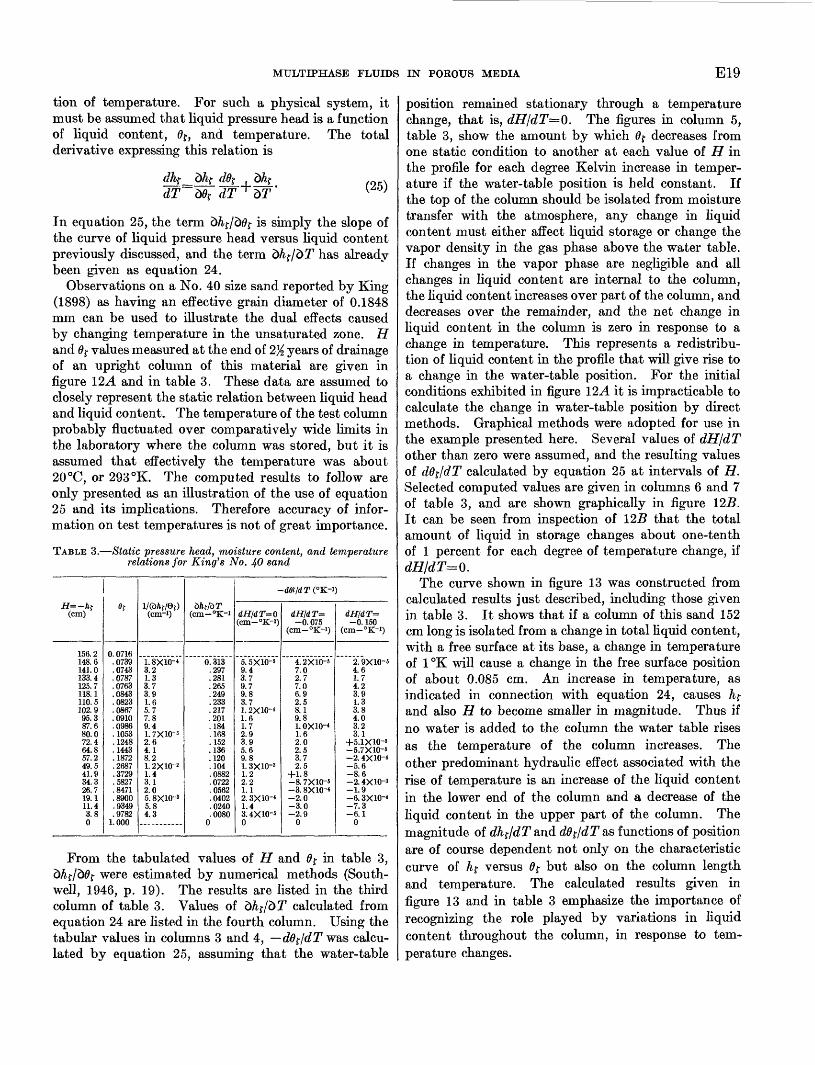
MULTIPHASE FLUIDS IN POROUS MEDIA E19
tion of temperature. For such a physical system, it must be assumed that liquid pressure head is a function of liquid content, 0£, and temperature. The total derivative expressing this relation is
(25)
In equation 25, the term d&r/d0f is simply the slope of the curve of liquid pressure head versus liquid content previously discussed, and the term d/^/dT has already been given as equation 24.
Observations on a No. 40 size sand reported by King (1898) as having an effective grain diameter of 0.1848 mm can be used to illustrate the dual effects caused by changing temperature in the unsaturated zone. H and 0j- values measured at the end of 2% years of drainage of an upright column of this material are given in figure 12A and in table 3. These data are assumed to closely represent the static relation between liquid head and liquid content. The temperature of the test column probably fluctuated over comparatively wide limits in the laboratory where the column was stored, but it is assumed that effectively the temperature was about 20 °C, or 293 °K. The computed results to follow are only presented as an illustration of the use of equation 25 and its implications. Therefore accuracy of infor mation on test temperatures is not of great importance.
TABLE 3. Static pressure head, moisture content, and temperature relations for King's No. 40 sand
H=-h{(cm)
156.2148.6141.0133.4125.7118.1110.5102.995.387.680.072.464.857.249.541.934.326.719.111.43.80
0f
0. 0716.0739.0743.0787.0763.0843.0823.0867.0910.0986.1053.1248.1443.1872.2687.3729.5827.8471.8900.9349.9782
1.000
l/(dAf/Q{)(cm-i)
1.8X10-43.21.33.73.91.65.77.89.41. 7X10-32.64.18.21. 2X10- 21.43.12.05. 8X10-35.84.3
dftf/dT(cm-°K-i
0.313.297.281.265.249.233.217.201.184.168.152.136.120.104.0882.0722.0562.0402.0240.0080
0
dH/dT=Q(cm- K )
5.5X10-59.43.79.79.83.71.2X10-41.61.72.93.95.69.81. 3X10-31.22.21.12.3X10-41.43. 4X10-50
-WC'K-,
dH/d T -0.075
4. 2X10-57.02.77.06.92.58.19.81.0x10-41.62.02.53.72.5
+1.8-8. 7X10⁻⁵-3. 8X10⁻⁴-2.0-3.0-2.9
0
)
dH/dT=-0.150
2. 9X10-54.61.74.23.91.33.84.03.23.1
+5.1X10⁻⁸-5.7X10⁻⁶-2.4X10⁻⁴-5.6-8.6-2. 4X10⁻³-1.9-6.3X10⁻⁴-7.3-6.1
0
From the tabulated values of H and 0 r in table 3, d/if/d0f were estimated by numerical methods (South- well, 1946, p. 19). The results are listed in the third column of table 3. Values of d/^/577 calculated from equation 24 are listed in the fourth column. Using the tabular values in columns 3 and 4, dd^/dT was calcu lated by equation 25, assuming that the water-table
position remained stationary through a temperature change, that is, dH/dT=Q. The figures in column 5, table 3, show the amount by which 6$ decreases from one static condition to another at each value of H in the profile for each degree Kelvin increase in temper ature if the water-table position is held constant. If the top of the column should be isolated from moisture transfer with the atmosphere, any change in liquid content must either affect liquid storage or change the vapor density in the gas phase above the water table. If changes in the vapor phase are negligible and all changes in liquid content are internal to the column, the liquid content increases over part of the column, and decreases over the remainder, and the net change in liquid content in the column is zero in response to a change in temperature. This represents a redistribu tion of liquid content in the profile that will give rise to a change in the water-table position. For the initial conditions exhibited in figure 12.4 it is impracticable to calculate the change in water-table position by direct methods. Graphical methods were adopted for use in the example presented here. Several values of dH/dT other than zero were assumed, and the resulting values of ddf/dT calculated by equation 25 at intervals of H. Selected computed values are given in columns 6 and 7 of table 3, and are shown graphically in figure 125. It can be seen from inspection of 125 that the total amount of liquid in storage changes about one-tenth of 1 percent for each degree of temperature change, if dHldT=0.
The curve shown in figure 13 was constructed from calculated results just described, including those given in table 3. It shows that if a column of this sand 152 cm long is isolated from a change in total liquid content, with a free surface at its base, a change in temperature of 1°K will cause a change in the free surface position of about 0.085 cm. An increase in temperature, as indicated in connection with equation 24, causes h{ and also H to become smaller in magnitude. Thus if no water is added to the column the water table rises as the temperature of the column increases. The other predominant hydraulic effect associated with the rise of temperature is an increase of the liquid content in the lower end of the column and a decrease of the liquid content in the upper part of the column. The magnitude of dhf/dT and dd^/dT as functions of position are of course dependent not only on the characteristic curve of hf versus 0f but also on the column length and temperature. The calculated results given in figure 13 and in table 3 emphasize the importance of recognizing the role played by variations in liquid content throughout the column, in response to tem perature changes.

E20 FLUID MOVEMENT IN EARTH MATERIALS
120
80
40
o
VNo 40 sand
E 0 0.2 0.4 0.6 0.8 1.0
1
1
1'
O II
K
\-v-\
/
§E
\'*
3 'o O O1C
\\
«.
-3 C
ino0
1
,
\ \\
>?
5 C:>
MOISTURE CONTENT .EFFECT OF TEMPERATURE ON MOISTURE DISTRIBUTION
A E
FIGURE 12. Static head, moisture content, and temperature relations for a sand. (Data from King, 1898.)
0.15 r
lOXlCf 5
INDEX OF TOTAL CHANGE IN LIQUID CONTENT, PERDEGREE CHANGE IN TEMPERATURE (o^/oTFROM
COMPUTED VALUES AT INTERVALS OF HAS IN TEXT)
FIGURE 13. Gross changes in storage above the water table as a function of temperature and water-table position for a sand.
Gardner (1955) studied the relation between tem perature and liquid pressure head on sand, sandy loam, and muck soil samples in the laboratory. His experi mental results appear to contain effects of vapor phase transfer on liquid content not considered in the forego ing discussion. One-liter volumes of soil were moist ened to less than field capacity and packed in bottles each containing a tensiometer. The sample bottles were immersed in a water bath for temperature control. The samples were isolated from the atmosphere except for a capillary-sized vent. Thus the total pressure in the vapor phase was approximately atmospheric for all ob servations. Equilibrium values of temperature and liquid pressure head were read when the "mercury in
the manometers (tensiometers) came to apparent rest" and when the "temperatures in the cups and in the soil %6-% m<& from the cups were approximately equal * * *" (Gardner, 1955). The time required for this apparent equilibrium reportedly varied from a few minutes to 13 hours. Shorter periods of time were re quired to reach equilibrium for sample temperatures near room temperature, and longer periods of time were required for sample temperatures near freezing.
Gardner's expressed concern over possible nonsteady- state effects in the reported observations appears justi fied. His samples were initially at room temperature. Heating the sample perimeter would initially drive vapor toward the tensiometer located in the center, and this vapor should later return to the perimeter as ther mal equilibrium was approached. For a cylindrical container with a radius of 4 cm and a length of 20 cm, ignoring the effects of the container walls and ends on heat transfer, and assuming heat transfer by conduc tion only with a thermal diffusivity of 1X 10~3 cm~2 sec"1, the temperature change at the center of the sample would have reached 99.3 percent of the change applied at the perimeter within 12 hours. Vapor transfer as an added heat transfer mechanism in the sample would have a tendency to further increase the time required to reach essential thermal equilibrium. Woodside and Cliffe (1959) noted that essential thermal equilibrium was reached in a 5-cm thickness of sand under a temper ature difference of 30°C: after 48 hours if saturated at 25 percent liquid content by dry weight, 1YO hours at 4 percent, 200 hours at 2 percent and 60 hours at 0 percent liquid content, by dry weight. This example serves to

MULTIPHASE FLUIDS IN POROUS MEDIA E21
illustrate the possible effects of heat transfer by vapor movement on the time required for equilibrium in Gard ner's experiments. Gardner applied step changes of temperature equal to about 10 °C between most equi librium measurements, and therefore his test measure ments probably do not reflect true static conditions. A significant temperature gradient, though small, prob ably existed near the tensiometer in all measurements reported. The degree to which this affects his observa tions is unknown.
Characteristic curves of liquid pressure head versus temperature derived from successive heating and cool ing of a muck soil (Gardner, 1955, fig. 4, p. 261) are shown in figure 14. Note that head values at any given
Arrows indicate direction of progressive change in temperature of sample
0 10 20 30 40 50
TEMPERATURE, DEGREES CENTIGRADE
FIGURE 14. Measurements of temperature and liquid pressure head in a muck soil. (After Gardner, 1955, fig. 4.)
temperature progressively increased as the experiment continued. This was probably caused by progressive loss of moisture from the sample container. As can be shown by equation 6, the pore humidity was always near saturation. Heating would simultaneously in crease the vapor content in the pores and drive vapor out through the pressure relief vent. Cooling induced the flow of relatively dry room air to return to the sam ple container. The net loss of liquid from the sample appears to have caused a shift of nearly 100 cm head be tween the end of the last cooling period and heating to nearly 50°C.
It should be recognized that a very small change in the amount of liquid retained could cause this change in head. The density of water vapor in the pore space at about 25 °C is about 2X10~5 g-cm~3 . Heating over
695-719 63 4
the 0°-50°C range would drive about one-sixth of the gas volume and water vapor from the pore space through the relief vent by expansion. The vapor formed in the pore space upon heating is mostly derived from the liquid phase. The change in liquid content, A0f, over the 50 °C warming interval is approximately equal to the vapor density times the change in gas volume, or about 3X10~6 . The net change in pressure head, possibly due to loss of liquid, was indicated to be about 100 cm from a comparison of the last cooling and warm ing curves shown in figure 14. Thus the slope of the liquid pressure head versus liquid content curve (AAj/ A0f) at the liquid content of the sample is given by
100 =3X107 cm, approximately.3X10
Analysis of the cooling curve may be employed for qualitatively verifying the calculated slope of the liquid head versus liquid content curve. Upon cooling, the mass of vapor contained in the pore space will be reduced by condensation, because, as previously indi cated, the gas phase is very nearly completely saturated with water vapor at the observed liquid pressure heads. Thus, as the sample temperature is reduced, the liquid content, 0f , increases by the amount of condensation from the vapor phase. The mass of liquid and vapor contained in a unit volume of pore space may be related for cooling as follows:
(26)
in which mp is the mass of water vapor contained in each unit pore volume and mj- is the mass of liquid water contained in each unit pore volume. It is also recog nized that
and«v> a fo^Wlf==Pft7j-. V^W
Substituting the differentials of equations 27 and 28 in equation 26, and assuming that density of the liquid phase may be considered independent of temperature, we find
50f= (1 flf) dp,
pu pf is nearly equal to minus one, and, because the sample was relatively dry, (1 0f) is of the order of one. Therefore,
t£- (30)
At a temperature of 25°C, ^=1.3X10-° g-cnr^C- 1 .
From Gardner's observations the mean ^ was about
10 cm-°C~ 1 , and h^ 400 cm. These data, as

E22 FLUID MOVEMENT IN EARTH MATERIALS
finite-difference approximations, and equation 30 may be put in equation 25, which yields:
40°
768-298
9.250f 1.3X10- 6
Numerically the latter result is probably more nearly correct than the figure obtained from analysis of the warming curve. It is believed that the physical basis for the two analyses are sufficiently diverse, and the numerical results are sufficiently close, that one may conclude vapor transfer had a pronounced effect on the observations recorded by Gardner. Certainly it does not appear possible to justify the observations shown in figure 14 as representing changes due pre dominantly to the functional relation between tempera ture and surface tension. A more adequate study of Gardner's data would require a more precise estimate of the amount of vapor driven from the sample upon warming and consideration of the vapor driven into the pore space upon cooling. The latter would require knowledge of the room humidity and temperature, and the 6$ value at some time during the observations. However, the questions arising from the uncertainty as to the state of the thermal field and its effect on the observations reported preclude the desirability of a more detailed study.
It may be remarked that a more precise development of the vapor-liquid interrelations outlined above might form the basis for accurately measuring the slope of the liquid pressure head versus liquid-content curve at low moisture contents. Gravimetric methods have com paratively low accuracy where the liquid content in the sample is small. In observing a liquid pressure head versus liquid-content curve at small moisture contents in the laboratory, changes of liquid content could be effected by temperature control of the sample. Analysis of such data by means of equations like 26 to 30 may provide a more accurate observation of changes in liquid content at many points in the experiment than can be made by the more direct gravimetric methods.
EFFECTS OF SALTS IN THE LIQUID PHASE ON LIQUID PRESSURE HEAD AND LIQUID CONTENT
To this point, the static liquid pressure head versus liquid-content characteristics have been discussed only for pure liquids. On pages El 6-17, the reduction in vapor pressure caused by dissolved salts was mentioned briefly as a means for conveniently obtaining large h{ values in laboratory observations of liquid content versus liquid pressure head. Using the information presented there one might suspect that salt concentra-
tion, or differences in salt content, from place to place in the porous medium may have a pronounced effect on head or distribution of liquid. First consider the static occurrence of liquid described by equation 19,
(19)
from which it is recognized that h^ is proportional to the liquid-gas interfacial tension. According to Moore (1955, p. 503) aqueous solutions with ionic salts gen erally have a higher surface tension than pure water. The increase in surface tension caused by the ionic salts is comparatively small. For example, the surface tension of sea water with a density of 1.025 g per cm3 is only about 1 percent greater than the surface tension of pure water (Dorsey, 1940, p. 514).
Therefore considering the liquid phase only in two separate columns both comprised of the same type of porous medium, the relations between static liquid head and liquid content should be found very much alike re gardless of the salt concentration, provided the salt concentration were uniform in each column. However, salts may not be uniformly distributed in naturally oc curring earth materials because of differences in struc ture, land use practices, differences in rates of leaching, and other factors. Near the water table the salt con centration is usually much smaller than at points higher in the zone of aeration. Nonhomogeneous salt concen tration in the zone of aeration may play a significant role in the moisture distribution above the water table.
Some of the pertinent features of the relation be tween a salty-liquid system and a gas-solid system not apparent from the capillary tube hypothesis can be learned from a study based on equation 6, applied to the inverted capillary-sized U tube of figure 15. The in ternal radii of the two arms of the U are identical and uniform. The lower end of tube B is inserted beneath the free surface of pure water in the container on the right. Tube A is inserted beneath the surface of an aqueous ionic salt solution in the container on the left. The free surface positions in both are held constant and
Salty Pure
FIGURE 15. Vapor phase in vicinity of liquids.

MULTIPHASE FLUIDS IN POROUS MEDIA E23
at the same level. From equation 19 and the knowledge that surface tension and density change very little with the salinity in A, we expect to find HA very nearly equal to HH. It might be presumed, therefore, that this system is in a static condition. However, to satisfy static condi tions the vapor phase must also be static. This may be checked by applying equation 3 to the vapor phase. Accordingly,
HA =-RTlogpv/ps (31) and
HB=-RTlogpv/p0 (32)
Comparison of equations 31 and 32 shows that because ps is different from p0, the vapor phase cannot be under static conditions. Rather, there will be a continuous vapor flow through the U section from B to A causing dilution and an increase in temperature in A, and a de crease in temperature in B. If the salt content in the container on the left were held constant the system could never become static. Thus it is evident that salt distribution in the unsaturated zone will have compara tively little direct effect on liquid heads but will have a pronounced effect on the movement of the vapor phase.
As a consequence of the occurrence of dissolved salts in natural waters in porous media, measurements of liquid pressure head in unsaturated rocks, commonly made with tensiometers in field studies, are of doubtful accuracy. Certainly the conditions postulated for figure 15 may arise around tensiometer cups as installed in the field. Figure 16 schematically shows a tensiometer cup
BA o°°0ood __ __
%s&, m
FIGURE 16. Tensiometer in contact with moist soil.
associated with a segment of unsaturated soil. It is assumed that the tensiometer cup and the attached manometer line were filled with pure water, and the liquid solution in the porous medium at A contains ionic salts. The manometer connected to the tensiom eter cup can only reflect the correct pressure head in the soil liquid if the vapor phase is static. If the vapor phase is not static, vapor movement to or from the cup
assembly will continuously change the head values ob served in the manometer. From equation 3, for static conditions in the vapor phase, the pressure drop across the menisci of the soil solution is given by
(33)
(34)
and across the menisci of the porous cup by
» i/
It can be seen that the difference in head between the soil liquid and liquid in the tensiometer may be as much as pcA/p?g PcB/Ptg- This difference is equal to the osmotic pressure of the salty solution (Edlefsen and Anderson, 1943, equations 222, 226, and 227). ps and p 0 are significantly different even for comparatively dilute salt solutions. Ordinarily then the tensiometer observation, unless corrected for errors due to this dif ference, may indicate liquid pressure heads appreciably greater in magnitude than those which actually exist. If the soil-moisture content varies slowly, static condi tions might be postulated because the amount of vapor available for transfer from the cup is restricted by the limited tensiometer storage. Such a restriction was not implied in connection with figure 15. Actually the errors in the tensiometer readings may be any value between zero and the osmotic pressure of the soil solu tion, depending on rate of change of 0f, the degree of liquid phase continuity between the soil and cup, and other factors.
Breazeale and McGeorge (1955) showed the effects of salinity on liquid content in the wilting range by a labo ratory study. Soil water was depleted to the wilting point by tomato plants. The soil salinity was con trolled by first desalinizing the original field samples. Equal parts of sodium chloride and sodium sulphate were then added to produce various salinity levels in the liquid retained up to a total of 1,000 ppm salt. Presumably in the experiments the relative humidity of the soil air was controlled by the plant at wilting and was therefore relatively independent of the salt content. Thus, pv as observed in the various suites of samples was relatively independent of the salt content of the liquid phase. The free solution vapor pressure, ps , decreases as the salt content is increased. Therefore, according to equation 33, as the salt content increases, for a given pore vapor pressure, the value of pCA in creases. Or, in effect, the liquid pressure head tends toward zero. In turn, this causes a higher percentage of moisture to be retained with increasing salinity, in ac cord with equation 19. The data shown in table 4, taken from Breazeale and McGeorge (1955 ) , verify this. Evi-

E24 FLUID MOVEMENT IN EARTH MATERIALS
TABLE 4. Soil-water salinity and moisture point for tomato plank
[After Breazeale and McGeorge (
Soils and solution
Safford soil, Cajon deep silted phase: Desalinized. _ ____________________Desalinized plus 100 ppm salt____ __Desalinized plus 500 ppm salt. ______Original- _______ ____ _____ _____
Mesa soil, Laveen clay loam: Desalinized. __ _____ _ _ ________Original________ ___ _ ______Desalinized plus 100 ppm salt___ ___Desalinized plus 500 ppm salt. ____Desalinized plus 1,000 ppm salt __ __
Vinton soil, very fine sand: Desalinized.. __ ________________Original ___ _______ ___ __ _____Desalinized plus 100 ppm salt __ _ _Desalinized plus 500 ppm salt
Pima soil, very fine sandy loam: Desalinized __________ ____________Desalinized plus 100 ppm salt___ ___Desalinized plus 500 ppm salt. ______Original--.. ________ _________ __
content at t
1955)]
Conductivity of saturation
extract (mmho-cm i]
1.92.83.35 1
Q
1.31.62. 33.0
1.02.52.63.9
2. 13.45.2
14. ^
he wilting
Tomato plant
wilting percentage (by weight)
15.918. 118.920.0
6.77 Q
7.18.58.9
3.63.94.04.8
9.310.412.813.2
dently the functional relation between moisture content and salinity is dependent on the liquid pressure head versus liquid-content characteristic of the soil, the os motic pressure of the soil-water solution, and its dis tribution in space.
Fox (1957) suggested applying these relations to de termine the amount of moisture available to plants in soils containing saline solutions. The significance of the relation of salinity to osmotic pressure is apparent through the work of Campbell and others (1948). They plotted electrical conductivity and total cations in milliequivalents per liter (meq per 1) against osmotic pressure and electrical conductivity versus milliequiva lents per liter as observed in saturation extracts. They calculated osmotic pressures from observed freezing point depressions and measured electrical conductivities with special laboratory apparatus. Their results are shown in figure IT. Typical potable ground water gen erally falls within the range of 1-10 meq. per 1 total cations. The osmotic pressure associated with this range would be between 0.03 and 0.3 atmospheres or approximately 30 to 300 cm of water, as found by ex trapolating milliequivalents per liter versus the osmotic pressure curve of figure IT. Thus the liquid pressure head versus liquid-content distribution is affected very strongly by comparatively small differences in salt dis tribution in the profile. For example, the sand charac terized in figure 12A under static conditions in the vapor phase could remain saturated at the top of the
TOTAL CATIONS, IN MILLIEQUIVALENTS PER LITER
110.0
6
3
1.0
0.6
0.3
0.1
0.06
n rw
3 6 10 30 60 100 3£
X/
/
/
/
/
fr
/
/
/
1
/
//
/\
/
y7/
/
0 100
60
30
10
6
3
1
0.
0
0.6 o
1 3 6 10 30 60 100 300
ELECTRICAL CONDUCTIVITY, MILLIMHOS PER CENTIMETER
FIGUKE 17. Quality, electrical conductivity, and osmotic pressure relations for soil-water extracts. (After Campbell and others, 1948, fig. 1.)
column if the cation content were 4 meq per 1 at the top and nearly zero at the bottom.
It is, however, doubtful that static conditions could exist in a porous medium in nature where the salt con centration differs appreciably from place to place. If, in the case cited in the previous paragraph, the upper section of the sand column became nearly saturated by vapor motion from the free surface of pure liquid at its base, gravity would cause the salty solution in the liquid phase to flow downward. It is more likely that such flow would continue until the pure water became con taminated and the salt concentration above was diluted by flushing. Presumably this action would continue all along the profile until both the liquid and vapor sys tems reached static conditions. Evidently tine salt con centration must be uniform over the profile if static conditions are to prevail in both phases simultaneously.
MULTIPHASE FLOW
GENERAL FLOW RELATIONS
Flow through unsaturated porous media is a multi phase process that is far more complicated than flow through saturated media. The rate of flow is dependent on the configuration of the liquid and gas phases in the pore space and on energy gradients formed chiefly by spatial changes in the pressure, temperature, and chemical content of the fluids in the pores. Flow char acteristics are described by the conductivity of the me dium to the passage of fluid under a specified energy gradient in much the same way that the coefficient of permeability (Wenzel, 1942) has been used for defin ing the flow characteristics of saturated aquifer mate-
MULTIPHASE FLUIDS IN POEOUS MEDIA E25
rials. The term conductivity will be applied in this report to flow characteristics of unsaturated media so as to distinguish these from references to the nature of flow in saturated media.
Considering the nature of multiphase flow of water, three basic types of conductivity may be distinguished, each defining the potential mobility of the liquid, gas, and vapor phases. Individually, each of these types might be subdivided further according to the type of energy gradient creating flow. Liquid may be driven through porous media by pressure, temperature, or salinity gradients for example. Thus the conductivity of a medium to liquid flow, Kf, might be expressed in terms of the unit gradient for each form of energy. This holds also for the vapor and gas conductivities, Kv and Kg respectively. Evidently the conductivity values must be defined in terms of the particular energy drive involved, unless it can be shown that the various energy forms can be interrelated and their total effect defined by a tensor. As used in this report, the term "conductivity" is defined as the rate at which fluid moves through a unit cross-sectional area, taken normal to the direction of flow, under a unit gradient of the appropriate form of energy. Although the thermal and chemical effects on unsaturated flow have been studied at some length, practical computations for predicting the flow within prescribed boundaries are still limited mostly to those cases in which unsaturated flow can be treated as a pure liquid system, completely independent of heat flow.
The general relations among conductivity to liquid flow, velocity of liquid movement, and pressure poten tial were discussed by Buckingham (1907) in connec tion with the movement of soil moisture. He pointed out that decreasing 0f reduces both the area of liquid- filled pore space available to flow and the number of continuous flow paths through the liquid phase. Thus the liquid conductivity decreases with decreasing 0f . Zero liquid conductivity was presumed only for zero liquid content. Richards (1931) reasoned that gas occupying part of the pore space influenced the liquid flow in basically the same manner as if the gas were a solid. Thus, liquid flow that results from head gradi ents applied across a short section of unsaturated media should follow Darcy's law, at least approxi mately. This relation may be stated as
(35)
where v^ is the bulk velocity of the liquid phase, I is length taken along the direction of flow, and X is the angle between the direction of flow and the horizontal.
According to Scheidegger (1957, p. 154-156), at about the same time that Richards and others working
with soil moisture migration forwarded this postulate, workers hi the oil industry were also suggesting that Darcy's law be applied to liquid flow through unsatu rated porous media. Experimental observations dating from about 1930 in the chemical, oil, and soils disciplines gave considerable support to this hypothesis and by now it appears to have reached acceptance (Irmay, 1954; Pirson, 1958). As will be indicated later, Darcy's law is an inadequate approximation where the flow of water and water vapor become interdependent. Even by intuitive reasoning one might certainly question the applicability of Darcy's law for describing the complex flow of liquid and vapor. For some flow regimes over which 0$ is comparatively high, omission of flow con tributions in the vapor phase may be justified. It must be recognized, however, that even at large 0j values, the distribution of thermal and chemical poten tials may cause more liquid motion than do the liquid- head gradients if the latter are relatively small. Therefore the degree of approximation hi expressing flow and energy relations must be devised with an acute respect for all the conditions causing flow.
Within the general class of naturally occurring porous media, approximate grain shape is restricted mostly to spheres or plates. For two assemblages of spherical grains, each packed identically but of different grain size, the pore shapes are congruent, and the two pore systems differ only by a factor of length. In study of static liquid occurrence, it has been noted that the liquid configuration in the pore space is closely related to the liquid content. Thus for a given value of 0j- in the pore space, we may perceive that the relative interconnections among liquid elements are nearly con gruent regardless of the size of grain. At any given 0$-, then, the proportionate reduction in permeability due to decreasing the number and continuity of liquid elements should be somewhat similar for all grain sizes. Variability in this relation is contained within the limits of grain shape and packing arrangement differences as found especially in natural media. This concept is important to the study of unsaturated flow because it permits grouping of natural porous media under com paratively few forms of conductivity versus 0 f curves. At any given 0f the conductivity may be expressed conveniently in dimensionless form as a relative con ductivity. The relative conductivity is defined as the ratio of (1) the conductivity to fluid flow at 0f and (2) the conductivity to fluid flow at 0f=l. In this report, relative conductivity of the liquid phase is denoted by KT f and of the gas and vapor phases by KTg and KTV respectively.
Schematic curves of relative conductivity, as may be obtained by laboratory measurements (Wyckoff and Botset, 1936, for example), are shown in figure 18

E26 FLUID MOVEMENT IN EARTH MATERIALS
1.0
01.00 0.5
FRACTION OF PORE VOLUME FILLED WITH LIQUID (6)
FIGURE 18. Schematic relative conductivities for wetting liquids and gas phase
for the liquid and gas phases. The potential field driving either phase is presumed to be derived from control of the pressure gradient only, whereas the temperature and chemical gradients are presumed to be zero. Furthermore, in measuring liquid flow rates the gross movement of the gas phase was held to zero ; and, conversely, in measuring the gas flow rates the gross movement of the liquid phase was held to zero. In the funicular stage the gas content is discontinuous through the pore space, and therefore the gas con ductivity should be zero, by definition. The minimum liquid content in the funicular stage is thus given by the intercept KTg Q near 0f =0.8 in figure 18, for example. Liquid continuity in some form is indicated by the Kr$ curve down to a 0j- of about 0.2, showing possible finite conductivity to liquid in the pendular stage.
The curves of figure 18 apply for fluid flow under controlled conditions. That is, only one fluid type is permitted to move in each set of observations. If this control were not exerted, liquid movement may induce parallel movement of the gas phases or nonwetting fluids. The results of Leverett and Lewis (1941) show the area of concentration levels in which appreciable movement was noted in more than one fluid. The rel ative concentrations of oil, water, and gas found in a permeable sand, after fluid mixtures of constant com position flowed through the sample until equilibrium was attained, are given in figure 19 A. The relative conductivity to oil for this system is shown in figure 195. A comparison of these data shows that flow by induction with an adjoining fluid would likely be com
paratively insignificant. Thus, each fluid or phase held in the pores may be considered as an individual flow, unaffected by adjacent fluids. This conclusion, how ever, may not hold for the water-water vapor and air system. For relatively volatile liquids like water, in teraction between the liquid and vapor phases may pre clude their separation and treatment as individual fluids in the pore space. Most studies of unsaturated flow have been made with the assumption that motion of each fluid or fluid phase is independent of the others, and comparatively little advance in the theory of flow of interacting fluids has been made.
100 percent gas
JOO percent water 100 percent oil
100 percent gas
100 percent water 100 percent oil
BFIGURE 19. Multifluid flow data. (After Leverett and Lewis, 1941.) A, Com
position of pore fluid and parallel fluid flow; B, Relative conductivity to oil, in percent, versus pore-fluid composition.

MULTIPHASE FLUIDS IN POROUS MEDIA E27
MEASUREMENT OF LIQUID CONDUCTIVITY
Conductivity measurements are made using virtually the same techniques employed for permeability measure ments. In the latter, the head or pressure difference across a saturated and confined sample of the porous medium is controlled, and the resulting gross velocity of liquid, 0f , is observed (Wenzel, 1942). The perme ability is calculated from these observations. Conduc tivity measurements differ from permeability measure ments in that more than one fluid must be subjected to control and measurement, and the degree of satura tion by the principal flowing fluid must be determined because conductivity is dependent on the degree of saturation. Field observation of a complete relative conductivity versus 6$ curve is not practical now because multiple control and measurement is required over a wide range of 0f values. An adequate range of 0f is not usually found at any one place over a conveniently short period of time. The inadequacy of field equip ment also prohibits accurate field measurement of conductivity over an extended range of 6$ values. In most instances accurate conductivity measurement over a sufficient range of 0f values are attainable only by laboratory techniques.
The basic features of equipment used for measuring liquid conductivity of core samples are shown schemat ically in figure 20. The sample (a) is held in a gas chamber (c) supported at each end by fine porous disks (6). The disk material is selected so that gas from (c) will not pass through either disk, and both will remain saturated if the drop in total pressure across either disk is greater than the maximum value of hf of interest. Chambers (e) are kept full of liquid during the conductivity tests and liquid continuity between (e) and the contained sample is maintained through disks (6). Either the pump shown or a gravity
Differential pressure gage
Pump Flowmeter
FIGURE 20. Schema of liquid conductivity measurement apparatus: (a) sample, (6) porous retaining disks, (c) gas chamber, (d) impermeable sleeve and support, and (e) liquid distribution chamber.
drive may be used to produce a head difference across and hence flow through the sample. The rate of liquid flow at any given degree of saturation is monitored at the flowmeter. This information may be converted to gross liquid velocity if the cross-sectional area of the core is known. The conductivity may be calculated from equation 35, the observed velocity, and the ob served head gradient.
Any one of several methods might be adopted for finding the value of 0f for a particular test run. The difference between the mean liquid pressure head applied at the ends of the sample and the head in (c) equals the hf across the gas-liquid interfaces. This head may be compared with the static liquid pressure head versus liquid content curve (discussed on pages E4-22) of the sample to determine 0r for each test run, or the core may be removed from the holder at the end of each run for a more direct method of measuring 0f . A continuous accounting of the inflow and out flow of liquid, and a material balance check, through all measurement runs, could be kept to indicate in directly the residual 0f in the sample and its changes from one run to another without dismantling the test equipment.
The most critical feature of the liquid-conductivity measurement equipment is the porous disk (6). Its primary function is to act as a hydraulic filter. In most testing methods the gas phase from chamber (c) is not permitted to flow through (6), whereas the liquid phase does flow from one retaining disk through the sample and out of the opposite retaining disk. Such control is obtained by selecting the material for disks (6) so that the disks will retain liquid in the capillary or funicular stages at all values of hf to be established in the sample.
Special-purpose testing required by oil-reservoir engi neering for evaluating oil-drive techniques has given rise to the development of many laboratory conductivity devices. Scheidegger (1957, p. 157-163) has discussed the relative merits of the more popular equipment and appended an excellent set of references to the basic literature on instrumentation and measurement of con ductivity. A more detailed description of a few of the laboratory techniques is given by Pirson (1958, p. 74-87).
Conductivity measurements made in the laboratory yield highly accurate results; error is usually less than about ±2 percent. However, the cost of such measure ment in terms of funds and time is comparatively high. Even though the conductivity measurements are needed to identify the hydraulic properties of the unsaturated zane, the cost of measurement is not so readily justified for water exploration as it is for oil exploration.

E28 FLUID MOVEMENT IN EARTH MATERIALS
An alternative method of obtaining the conductivity versus 0f curve would be desirable. Richards and Weeks (1953) describe a system of observing flow rates and tension on a soil column about 1 foot in length, under nonsteady flow conditions, from which conductivity can be estimated. Liquid head is measured by standard tensiometer equipment at several points in the sample, and these head values are used as an indication of 0f by comparison with the liquid content versus liquid- head curve obtained from static measurements. Con ductivity values may be calculated, from these measure ments, taken over a period of nonsteady flow, by finite-difference approximation of the differential equa tion of nonsteady liquid movement.
Rose (1951) also discussed measurements of this nature, with special reference to the time required by the tensiometers to reach equilibrium with the liquid phase. He emphasized the difficulty of obtaining cor rect head measurements if only a small amount of liquid was contained in the sample. Low conduc tivities in the sample, associated with small 0f, result in slow manometer response. A procedure for adjust ing the manometer positions to minimize lag in response of the manometer due to storage changes in the liquid phase as the tests proceed was offered. Minimizing storage changes in the manometer reduces the time needed for attaining equilibrium between the sample and tensiometer and thereby reduces the time needed for laboratory observation.
CALCULATION OP LIQUID CONDUCTIVITY
A less costly approach to determining conductivity than by laboratory measurement alone might be found through making measurements for a relatively small number of 0f values and interpolating between measured values, or possibly defining the entire curve by calcu lation from the curve hf versus 0$-. The fundamental characteristic that best defines the liquid content of the medium is the curve of liquid content versus liquid pressure head, which is obtained from static observa tions. But in order to relate the static liquid occurrence to the steady-flow characteristics there must be a clear definition of the configuration of the pore liquid as a function of 0f . As indicated by Miller and Miller (1956), the interconnections between liquid filaments in the pore space are complicated, and it is difficult to obtain a completely sensible model of unsaturated liquid flow in terms of interconnected capillary tubes. However, the simplified capillary tube models remain as the chief basis for developing methods of computing liquid conductivity.
Childs and George (1948) assumed that pore space may be modeled as a bundle of parallel cylindrical capillary tubes of various sizes. For the cylindrical
capillary tube, equation 5 states that hf is proportional to l/ret. Accepting the capillary tube model allows viewing the 0j- versus A-j- static relation as an index of an rcl versus 0f curve. Thus the hf versus 0? curve may be employed directly for estimating the pore-size distribution at any degree of saturation. Poiseuille's well-known equation for flow through capillary tubes was applied to each pore size. A summation of the relative contribution of flow from each size by this means yields a figure for relative conductivity of the medium. This procedure was used by Childs and George for calculating the curve shown in figure 21.
15
10
Calculated..
/s^^
Observed
0.1 0.2 0.3 0.4
WATER CONTENT, AS FRACTION OF TOTAL APPARENT VOLUME
FIGURE 21. Calculated and observed conductivities versus liquid content. (After Childs and George, 1948.)
They compared their calculated results with a set of conductivity observations made on the sample, a sand whose grains ranged between 0.5 and 1.0 mm in diameter. The calculated curve was arbitrarily matched with the observed value of conductivity at 0f/<£=0.3.
Rather than the Poiseuille equation for flow in a filled cylindrical tube, Rapoport and Leas (1951) used Kozeny's equation relating the solid-liquid interface area to permeability for weighting the relative con ductivity of any given continuous liquid element. In Kozeny's equation the total surface area was taken to include both the liquid-solid and the liquid-gas inter face areas. The liquid-gas interfacial area was obtained by use of the principles of thermodynamics. The latter investigation defined maximum and minimum liquid-gas areas for any given value of 0f, which were applied through Kozeny's equation to find a maximum and minimum value of relative conductivity. The

MULTIPHASE FLUIDS EST POKOUS MEDIA E29
final expression for ^r(mas) obtained from analysis of this model may be written as
(36)
where
l-0o (37)
(38)
(39)
(40)
In equations 37 through 40, 80 is that liquid content, expressed as a fraction of the total pore volume at which the conductivity to liquid flow is zero, and hfm is the mean liquid pressure head hi the range 8f to 60 . The minimum relative conductivity at any given 0f value was found to be
wherein the definitions given by equations 37 through 40 apply. It may be noted that all the integrals defining the terms of equations 36 and 41 simply refer to specified areas under the 6$ versus hf curve. Thus, Krrcmax) an^ ^{-(mm) are easily evaluated by graphical or numerical methods.
The Kozeny equation used as a model for developing equations 36 and 41 contains a constant dependent on the tortuosity of the liquid-flow paths, which has been assumed by Kapoport and Leas to be hi dependent of Of. The validity of equations 36 and 41 is hi question because the relation between 0f and tortuosity does not appear to be constant (Burdine, 1953). Wyllie and Gardner (1958a, b) developed a model of porous media using somewhat the same viewpoint as Childs and George (1948), except for the variability due to tortu osity, and derived the folio whig:
..__Q2
C ef
J90(42)
wherein the term 02, defined by equation 37, accounts for a variable tortuosity. Equation 42 reportedly yields estimates of Kr { highly compatible with labora
tory test results on a wide variety of natural porous media. The integrals hi equation 42 may be evaluated simply by numerical or graphical interpretation of the hf versus 6? data. Evidently the amount of computa tion needed to adequately define the KT[ versus 6? curve by equation 42 is much less than is required for solving equations 36 and 41. Thus equation 42 is preferred provided it is eventually shown to yield relia ble predictions. For those media in which l/h*f is a linear function of 0 it can be shown (Wyllie and Gardner, 1958b) that,
Krf^Q. (43)
However, it seems doubtful that the simplified form of Krf represented by equation 43 can be applied without reservations. A linear relation between l/h*f and 0 has not been noted except for a few samples, or over a short range of 0 values. In most of the tests over the range of 6? from 60 to 1, this relation generally has been observed to be nonlinear.
The equations for Krf given above, and the empirical tests made to judge their validity, show that KT f at low moisture contents is highly dependent on B0. At the present tune, however, there does not appear to be a way to measure or observe 60 directly. For coarse grained and well-sorted material, 60 might be estimated by inspection of the hf versus Of curve. It is known (Smith, 1933b) that the slope of the latter curve is much greater for the pendular stage than for the fu nicular stage. Thus, 60 for the hf versus 6f curve of figure 12^4 might be assumed approximately equal to 0.08. However, the 6f value at which moisture distri bution is entirely pendular probably extends to some much higher value, if it is correct to assume that liquid conductivity is zero over all the pendular stage (Smith, 1933b). The latter assumption, however, cannot be upheld by evidence hi the literature. Thus estimation of a reliable 80 value from static observations alone does not appear feasible. Kather, it has been suggested by many that the Krf versus Of relation may be determined by combining calculations based on an equation like 41 with a few measured relative conductivities. The shape of the relative conductivity curve is calculated for several assumed values of 60 by equation 41 and these are matched to the selected measured values. The computed curve providing the best fit to the measured values is then taken as the medium charac teristic sought, affording also an indirect measurement of 60.
DIFFERENTIAL EQUATION FOB LIQUID FLOW
In a pore space filled with water, water vapor, and gas, all three fluids are free to move with varying de grees of mobility depending on their relative concen-

E30 FLUID MOVEMENT IN EARTH MATERIALS
tr at ions and the energy distribution in the flow system. At high liquid concentrations in most natural environ ments, it is probable that the vapor and gas motion neither retards nor augments the liquid flow appreci ably. Under these circumstances, the movement of liquid water may be defined without reference to the other fluids contained in the pores. In any given in finitesimal element of such a flow field, the rate of change in mass of stored liquid equals the spatial change in mass flow. This continuity relation may be expressed as
(44)dx
where t refers to time. Provided the liquid density is constant at all points and is uniform from place to place, equation 44 may be written as
(45)
For the type of flow assumed here the gross velocity of liquid may be expressed in terms of h{, according to equation 35. Making the indicated substitution and taking z to be the vertical axis, equation 45 becomes
Ldx2 J+ d.r dx
Richards (1931) is generally credited as being one of the pioneers in adopting the concepts of tmsaturated liquid occurrence and movement embodied in equations 35, 44, 45, and 46. These fundamental concepts have gradually gained acceptance because observed heads and liquid contents are comparable generally with those predicted from the above equations for liquid flow systems.
Equation 46 may be written in any one of several combinations of variables selected for convenience of application. Dividing through by the permeability of the medium converts the conductivity to the rela tive conductivity. Assuming that hs and K$ may be expressed as single-valued functions of 8$, equation 46 may be written in terms of only 0 £ , for example.
The construction of equation 46 does not in itself presume limitations on the functional relations among K$, 0£, and h$. However, solutions to equation 46 are easily obtained only through the further assumption that K$ is a single-valued function of either 6$ or h$, and that h$ is a single-valued function of 6$. The latter assumptions, in part, follow logically from the
more general conditions postulated: that all flow is in the liquid phase and that thermal and chemical effects on the flow regime are negligible.
It is known the relations among h^, 0$, and K$ are not single-valued in most porous media. On increase of the liquid content the value of h$ at a given 0j will be less than the h$ observed at the same value of 0j if the liquid content is decreased. An example is given in the adsorption-desorption curves presented in figure 31A, p. E48. Because the curves of (such as fig. 31A for example) h^ versus 0j observed over several wetting and drying cycles closely resemble the hys teresis curves noted in other stress phenomena, the multivalued relations are usually termed hysteresis effects. The geometrical shape of the pore space is generally recognized as the underlying cause of hys teresis, as described by Smith (1933a).
COMPUTATION OF ONE-DIMENSIONAL FLOW
As a general rule the relations among conductivity, liquid head, and liquid content are nonlinear, and K% is a function of h^. Therefore equation 46 is a non linear differential equation. Thus, analysis of un- saturated flow in more than one direction is virtually impossible by straight-forward methods of calculus. One must evidently resort to some form of approxi mation in order to obtain a solution, either in the ana lytical process adopted or in approximating the rela tively complicated K$ functions by simple algebraic expressions.
Richards (1931) discussed a solution of equation 46 for one-dimensional steady flow in materials for which the conductivity could be expressed as
(47)
where a and b are constants. At hf=Q the medium is saturated and therefore b in equation 47 apparently equals the permeability. Equation 47 is a good approximation (Gardner and Mayhugh, 1958) over the range l>0j->0.65. Even for the least complex bound ary conditions, however, equation 47 does little toward simplifying the solution of equation 46 for nonsteady flow.
Remson and Fox (1955) studied a case of one-dimen sional steady flow for
Ks=alht. (48)
Equation 48 specifies that the liquid conductivity is infinite where 0f=l. Where the unsaturated section above the water table is thick, the section near the water table, corresponding to the capillary fringe, normally contributes little resistance to flow compared with the drier sections higher in the profile, and perhaps equation
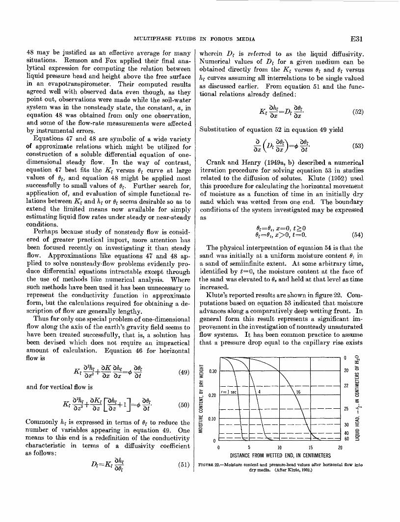
MULTIPHASE FLUIDS IN POROUS MEDIA E31
48 may be justified as an effective average for many situations. Kemson and Fox applied their final ana lytical expression for computing the relation between liquid pressure head and height above the free surface in an evapotranspirometer. Their computed results agreed well with observed data even though, as they point out, observations were made while the soil-water system was hi the nonsteady state, the constant, a, in equation 48 was obtained from only one observation, and some of the flow-rate measurements were affected by instrumental errors.
Equations 47 and 48 are symbolic of a wide variety of approximate relations which might be utilized for construction of a soluble differential equation of one- dimensional steady flow. In the way of contrast, equation 47 best fits the Kf versus 0r curve at large values of 0r, and equation 48 might be applied most successfully to small values of 0f . Further search for, application of, and evaluation of simple functional re lations between K$ and h? or 0r seems desirable so as to extend the limited means now available for simply estimating liquid flow rates under steady or near-steady conditions.
Perhaps because study of nonsteady flow is consid ered of greater practical import, more attention has been focused recently on investigating it than steady flow. Approximations like equations 47 and 48 ap plied to solve nonsteady-flow problems evidently pro duce differential equations intractable except through the use of methods like numerical analysis. Where such methods have been used it has been unnecessary to represent the conductivity function in approximate form, but the calculations required for obtaining a de scription of flow are generally lengthy.
Thus far only one special problem of one-dimensional flow along the axis of the earth's gravity field seems to have been treated successfully, that is, a solution lias been devised which does not require an impractical amount of calculation. Equation 46 for horizontal flow is
(49)
and for vertical flow is
(50)
Commonly A r is expressed in terms of 0r to reduce the number of variables appearing in equation 49. One means to this end is a redefinition of the conductivity characteristic in terms of a diffusivity coefficient as follows:
A=#rt^ (51)
wherein D^ is referred to as the liquid diffusivity. Numerical values of Df for a given medium can be obtained directly from the K$ versus 0f and 0r versus Af curves assuming all interrelations to be single valued as discussed earlier. From equation 51 and the func tional relations already defined:
Substitution of equation 52 in equation 49 yield
(52)
(53)
Crank and Henry (1949a, b) described a numerical iteration procedure for solving equation 53 in studies related to the diffusion of solutes. Klute (1952) used this procedure for calculating the horizontal movement of moisture as a function of time in an initially dry sand which was wetted from one end. The boundary conditions of the system investigated may be expressed as
0f=0s , #=0, t>Q8t=dt , z>0, t=0. (54)
The physical interpretation of equation 54 is that the sand was initially at a uniform moisture content 0; in a sand of semiinfinite extent. At some arbitrary time, identified by £=0, the moisture content at the face of the sand was elevated to 6S and held at that level as time increased.
Klute's reported results are shown in figure 22. Com putations based on equation 53 indicated that moisture advances along a comparatively deep wetting front. In general form this result represents a significant im provement in the investigation of nonsteady unsaturated flow systems. It has been common practice to assume that a pressure drop equal to the capillary rise exists
2 0.30
0 5 10 15 20 DISTANCE FROM WETTED END, IN CENTIMETERS
FIGUEE 22. Moisture content and pressure-Lead values after horizontal flow into dry media. (After Klute, 1952.)

E32 FLUID MOVEMENT IN EARTH MATERIALS
across the wetting front. Also it has been presumed that the pore space is completely filled with liquid and that conductivity is constant and equals the permeabil ity behind the advancing front. The latter presump tion is derived from the comparison of the pore space with a bundle of cylindrical capillary tubes and was studied in detail by Lambe (1951) . An application to infiltration was described by Stallman (1954). The curves of figure 22 indicate that both these assumptions are far from reality. The time period represented is comparatively short, but it can be seen that as time in creases, the depth of the "wetting front" increases, and conditions of flow tend to depart increasingly from the assumptions based on the capillary tube hypothesis. Other similar results show clearly that the simple cylin drical capillary tube model is inadequate for calculating, or even visualizing, liquid flow through unsaturated porous media.
Although the numerical iteration procedure of Crank and Henry (1949a, b) is a means for solving equation 53, it is laborious. Convergence to a satisfactory endpoint appears slow for the dift'usivity characteristics exhibited by most porous media. Philip (1955) devised a more rapidly converging iteration procedure for solving equation 53, subject to the conditions expressed by equa tion 54, and he tested the result by comparing it with an analytical solution available for a given case. Subse quently, this process was extended (Philip, 1957a) to encompass numerical solution of equation 50 subject to the conditions expressed by equation 54. The latter problem refers physically to downward infiltration of water from the soil surface. In essence, Philip's pro cedure for solving equation 50 is comprised of summing successive approximate solutions to a series of differen tial equations constructed from the basic equations of horizontal and vertical flow : equation 53 and a form of equation 50. His analysis leads to the following expression :
(55)
where z is the depth beneath the upper surface of a vertical column, comparable to the land surface in a natural environment; A, x, $, w, and fm (6[) are functions of 0f only, and t is the time since the moisture content at the upper end of the column changed. A is the function of 6$ found by solving equation 53, which applies to horizontal flow under conditions expressed by equation 54. x is the function of 0r found by solving an equation developed from the difference between forms of equations 50 and 53. Thus x may be considered as an approximate correction, which accounts only partly for the effect of gravity on vertical flow. The remaining functions of 0f in equation 55 are
determined in much the same way. All the values of /m(0r) are found by numerical solution of ordinary differential equations, each of which represents succes sive improvement in the treatment of gravity effects upon the liquid distribution in the profile. The details of the computing procedures and applications to infiltra tion problems are described by Philip (1955, and 1957a-f, and 1958a, b).
Youngs (1957) compared moisture profiles, produced in the laboratory on two types of porous materials under the conditions of equation 54, with profiles of liquid distribution calculated by Philip's methods. Good agreement was found between observed and calculated profiles. Gardner and Mayhugh (1958) also applied Philip's method to solve equation 53 subject to the con ditions of equation 54 for the porous media in which
where 0fi is the initial moisture content in the medium and D^ is the diffusivity before infiltration corre sponding with 0j-i, and a is a constant. Their pub
lished selected curves for 2<^p<4,000, where D^g is
the diffusivity at the input end of the medium after horizontal infiltration begins, are shown in figure 23. Laboratory observations agreed well with the calcu lated moisture content distribution over a wide range of Dft and Df,/Dft values.
It should be noted that although Philip's numerical procedure is evidently a highly convenient method of calculation, it was derived for a specified set of boundary conditions, and in the absence of further justification it cannot logically be applied to any other system of boundary conditions. Youngs (1958a, b) recognized this limitation in his studies of moisture profile changes occurring during and after a period of vertical infiltra tion from a surface source.
Nonetheless, this in no way detracts from its utility as a convenient means for testing the validity of the assumptions inherent in equation 50. In fact, it may be concluded from reported comparisons of calculated flow with laboratory studies that isothermal nonsteady liquid flow through porous media is adequately described by equation 50.
WATER-VAPOR TRANSMISSION
At very low liquid conductivities vapor movement in duced by chemical, liquid head, or temperature gradi ents may be of such magnitude that it is a significant part of the total fluid flow. Vapor transmission may be by simple diffusion through the gas contained in the pore space, or by convection with the gas should the gas be moving. Unsaturated flow in comparatively dry

MULTIPHASE FLUIDS IN POROUS MEDIA E33
D. = O.; exp a (9-
35
DIFFUSIVITY-DISTANCE-TIME RELATIONS, NONDIMENSIONAL
FIGTJBE 23. Calculated moisture profiles in nondimensional form for horizontal flow in semiinfinite medium. (After Gardner and Mayhugh 1958.) (6[ is the liquid content in the medium at time i=0and at distance x from the wetted end. Df is the diffusivity to liquid of the medium. The subscript fi refers to initial conditions in the medium at (=0 and x>0. The subscript (g refers to conditions at t>0 and i=0).
media may not therefore be assessed accurately by the concepts embodied in equation 46 alone, wherein flow in the liquid phase was presumed to account for all fluid motion. A study of the vapor motion should aid in defining those conditions for which equation 46 alone is a satisfactory approximation of fluid flow through porous media.
Much of the literature devoted to description of vapor movement in unsaturated media seems to be con cerned with explanations of applying the theory of vapor diffusion. Equations of water-vapor diffusion through gas-filled volumes are adjusted to account for the reduction of space caused by the occurrence of liquid in the pore space. The latter approach has led to much corollary speculation concerning the wide dis crepancies between measured and calculated rates of vapor flow.
Laboratory studies by Hanks (1958) indicate that the diffusion concept is adequate for estimating flow of vapor through the pore area in a section of dry mate rial. Agreement between his observed and predicted flow is to be expected, for both his test conditions and the conditions postulated in the diffusion equations em ployed are identical. The dry porous material per
forms only as a composite inert object occupying part of the volume available if diffusion were only through still air. If the gas phase is completely immobile, the rate of vapor flow indicated by the simplest concept of diffusion may be expressed as:
dpRT(P-pv} dx-£: (57)
where
qv is the rate of flow in g-cm~2-sec~1 y is a tortuosity factor and equals about 0.7 Dv is the coefficient of diffusion of water vapor into still
air, in cm2-sec~1 (equals about 0.239 cm2-sec~1 atQ0p\8 U),
and the remaining terms are as previously defined. Equation 57 was tested by observing vapor flow through a section of dry soil less than 1 cm thick. A wetted section was placed in contact with one end of the dry sample and vapor diffused through to the other end which was held at constant temperature and hu midity. The dry section was pretreated with Arquad 2HT to prevent condensation and movement of liquid

E34 FLUID MOVEMENT IN EARTH MATERIALS
on the solid surface. The rate of vapor transfer was calculated from successive weighings of the sample and sample container assembly. Measurements of vapor transfer were made for both anisothermal and iso thermal conditions over a wide range of moisture con tents in the wetted section. The value of Dv was ad justed for temperature and pressure (Krischer and Rohnalter, 1940) by the relation
(58)P \T
where the subscript zero refers to values at some stand ard set of conditions for which D0 is known.
Comparison of the vapor-flow rate, predicted by means of equations 57 and 58, with the flow rate observed experimentally indicates that equation 57 is valid for both isothermal and anisothermal diffusion of water vapor through dry soil. In connection with his figure 2, reproduced here as figure 24, Hanks (1958) indicated these relations may not hold exactly for low
0 10 20SOIL-MOISTURE CONTENT AT WETTED END, IN PERCENT
FIGURE 24. Water vapor diffusion through dry soil from wetted section in contact with sample. (After Hanks, 1958.)
moisture contents. Note in figure 24 that the observed vapor-diffusion rate drops off steeply as the moisture tension of the wetted section approaches and falls below the 15-atmosphere moisture content. (Whether the percentage of moisture content shown is a function of dry weight or porosity is not indicated by Hanks.) The curvature in this region may result partly from the measurements employed. Corrections for reduced relative humidity as liquid is removed from the wet-dry interface at the higher moisture tensions would tend to straighten the curve. In part, the curvature might also be due so movement of the "effective" interface position away from the dry section as the liquid in the wetted section is depleted by flow. These effects would be progressively more significant in the observa tions made as the soil-moisture content of the wetted
section was decreased. If both these conditions were appropriately accounted for, the range over which the diffusion rate appears independent of moisture content in the wetted section would probably extend to much lower values of 6$ in the wetted section.
In wet porous media the effect of liquid-vapor inter action may play a predominant role in the rate of vapor transfer. At moisture contents below Q0 it has been held that conductivity to liquid flow is zero and there is no interaction between the two fluid phases for the steady state. Yet even at liquid contents just slightly above zero, about 3 percent by dry weight in one group of experiments (Wong and others, undated), vapor movement was significantly greater than can be accounted for by the simple diffusion concept embodied in equation 57. Smith (1943) proposed that migration of liquid could be triggered by condensation, which would locally increase the liquid content above 00 and thereby locally create zones with a conductivity favor able to movement in liquid form. This view is strongly supported (Wong and others, undated) by detailed lab oratory observations. Others (deVries, 1958; Philip and deVries, 1957) have also indicated that there must always be some interaction or interdependence between the vapor and liquid phases, although this interaction may be negligible in extremely dry or wet porous media. Experiments reported by Solvason (1955) showed heat flow through porous materials was noticeably affected by the presence of water in liquid and vapor form.
Imposition of a temperature gradient across a moist porous medium can readily be seen equivalent to an imposition of differing stress from one section to an other. Consider the closed container filled with a moist porous medium, with a constant temperature difference maintained across two ends, and all other surfaces completely insulated as shown schematically in figure 25. If there should be no interaction between the liquid and vapor phase this system should eventually reach a static state, except for a continuous flow of heat from one side to another. According to equation 57, diffusion of the vapor phase through unsaturated media can be zero only if the term dpv/dx is zero over all the pore space. For static conditions in the vapor
Vapor flow
Liquid flow
Cool Moist porous medium
-'" J ""3 ' "-'"
Warm
FIGUEE 25. Schema of a sealed sample under a thermal gradient.

MULTIPHASE FLUIDS IN POROUS MEDIA E35
phase, h{ in the liquid phase becomes increasingly negative as temperature increases, according to the differential of equation 6 (p. ElO). According to equation 24 (p. E18), however, static conditions in the liquid phase will result in an hf becoming less negative at a comparatively low rate as temperature increases. Thus the net effect of static conditions in the vapor phase, while maintaining a temperature difference across the sample of figure 25, is a tendency for liquid to flow from the cool toward the warm side. This flow creates a vapor-pressure deficiency on the cool end and a vapor-pressure excess on the warm end, causing a flow of vapor from the warm toward the cool end. Evidently there can be no static occurrence of liquid and vapor in the sample controlled as shown in figure 25. That this is so has been demonstrated experimentally by Rollins and others (1954). Liquid evaporates near the warm end, flows as vapor toward the cool end where it condenses and flows back toward the warm end as liquid to close the cycle.
AVERAGE TEMPERATURE GRADIENT IN DEGREES CENTIGRADE PER CENTIMETER
FIGURE 26. Vapor flow rates versus temperature gradients, (After Rollins and others, 1954.)
Rollins and others (1954) connected the warm and cool ends, of an otherwise sealed system, externally through a capillary tube. The movement of liquid in the connecting tube was considered to be a measure of the vapor motion through the sample. It was postu lated that vapor condensed at the cool end of the sample and then entered and flowed through the external con necting tube to the warm end where it was evaporated and again entered the pore system. The flow rates per unit area observed in tests on one sample are shown in figure 26. At high-temperature gradients, calculated flow rates based on the simplified concept of vapor dif fusion (as expressed in equation 57) through the re stricted pore area were typically only about one-sixth of the observed rates. At low temperature gradients, the observed and calculated rates were in better agree ment but still sufficiently different to indicate some de viation between the nature of flow and the physical model used as a basis for calculating rates of vapor
movement. One cannot be certain which is responsible for the deviation noted, the model on which the calcula tions were based, or the method of measuring the rate of vapor flow. A temperature difference placed across the capillary tube in itself might cause the liquid move ment observed in the external capillary. Perhaps the external capillary acts to short circuit the flow of the liquid phase. Thus, there is no assurance that the liquid flow rate observed in the external capillary is a true measure of vapor flow through the sample.
Assuming that the liquid phase is immobile on the solid surfaces in comparatively dry media, one would not expect gravitational effects to influence the trans mission of heat appreciably. In equation 57, the term dpv/dx is not dependent on the direction of so with re spect to earth gravity. However, as indicated by figure 27, the net rate of heat flow through a clay sample (Woodside and de Bruyn, 1959) may be dependent on whether heat flow was upward or downward. Liquid circulation is directly affected by the gravity-force field,
4.25
^ 4.0
3.5
Heat flowup
Heat flowdown
10 15 20 25
TEMPERATURE GRADIENT ("F-IN )
FIGURE 27. Heat conductivity effects caused by gravity flow components. (After Woodside and de Bruyn, 1959.)
and the rate at which heat moves through the sample should therefore depend on the amount of heat trans ported through movement of the liquid phase. In a closed system, circulation of the liquid phase is depend ent on the degree of interaction between the liquid and gas phases. Thus the data of figure 27 indicate that such interaction was possibly contributing to the mech anism of vapor transmission. However, the authors note that the observed differences in heat flow may have been due to slight inequalities in densities and moisture contents in the samples tested or to convection within the gas phase.
The physical law expressed by equation 57 presumes that changes in the liquid phase do not affect the energy distribution or vapor content in the gas phase. At any rate it has been applied with this assumption as the basis for calculating rates of vapor flow. It seems quite apparent that this assumption is not an adequate ap proximation for describing the flow of water vapor

E36 FLUID MOVEMENT IN EARTH MATERIALS
through water-wet media, but this does not preclude use of the diffusion concept for developing a more com prehensive understanding of vapor flow. The law of vapor flow expressed by equation 57 may be expanded to include the interrelations with the liquid phase not accounted for in its development.
ANISOTHERMAL FLOW OF LIQUID AND VAPOR,
GENERAL RELATIONS
In comparatively dry or fine-grained material, gradi ents of temperature and head may be of equal import to the movement and distribution of fluids in the pore space. Such a system cannot be idealized as one of only liquid or vapor motion. A complete description of flow applicable over a broad range of moisture contents must include consideration of both the liquid and gas phases and the interrelations between them. Assuming there is an intimate relation between the liquid and vapor phases necessitates considering the system as being anisothermal.
Such flow along a short length of the flow path, A/, is shown schematically in figure 28. The fluid is
Change in storage
Outflow
Liquid phase
Evaporate
t
Gas
c^<0 ac o o
phase
Finite lengthalong flow path
Liquid = P v. 4 i
Inflow
FIGURE 28. Schema of combined anisothermal flow of gas and liquid through porous media.
composed of two separate phases, liquid and gas. At the inflow end of the section, arbitrarily taken at the right end, the gross velocity of liquid (the volume rate of flow per unit cross-sectional area of the porous medium) is defined as v^, and similarly the gross velocity of the gas phase is vg. The rate at which mass enters each unit area of the inflow end equals
where pf and pg are the densities of liquid and gas phases, respectively. Within the short interval of time, A£, there may be an interchange of mass between phases caused by condensation of vapor from the gas phase, or evaporation of the liquid phase. Thus, at the outflow end of the section the relative velocities or relative dis tribution of mass between the two phases may be differ ent than at the inflow end. Should flow be in the
steady state, no storage changes will take place in the interval AZ and m/in=m/OMf. Thus, for the steady state A0j-pf= A^pg, where the differences refer to changes between the inflow and outflow ends of the section. For nonsteady flow m/iw +Am/A£=m/0«* where Am/A£ is the rate of change of fluid stored in the element A?.
In the following it will be assumed that all the poten tial creating flow is derived from differential heads and temperatures applied across the space A?, and that in the gas phase only the vapor is free to move. Clearly, the temperature distribution along AZ will be affected by the liquid and vapor flow as well as by any inter change between these fluids, and, conversely, the flow in each phase is dependent on the distribution of ther mal energy. The three principal mechanisms involved in heat transport are:1. Conduction. A temperature gradient across AZ
causes heat to flow through the fluid-solid system at a rate proportional to the thermal conductivity of the system independent of fluid motion.
2. Convection. This term is here applied to identify heat flow through the medium of moving fluids. The rate of heat flow by convection equals the mass rate of fluid flow times the temperature times the specific heat in each phase. Thus convective heat transport is directly proportional to the fluid velocities.
3. Conversion. Wherever liquid is evaporated or vapor is condensed in the system, heat is liberated or con sumed to effect the phase transformation. Thus, heat sources and (or) sinks may be distributed along the length AZ, their strength being depend ent on the rate at which fluid locally undergoes a phase change.
The flow system illustrated in figure 28 is evidently vastly more complicated than isothermal liquid flow, which is completely defined by only one differential equation containing relatively few terms. Anisothermal flow, on the other hand, requires two differential equa tions, both of a more complicated form; each of which must include a host of interrelations among the laws of fluid and heat flow and among characteristics of the porous medium and fluid. A complete set of equations denning the anisothermal fluid system has not yet been developed. Although derivation of an adequate set of equations for anisothermal fluid movement is beyond the scope of this report, certain phases of the inter relations within this system will be discussed in the following.
LIQUID PHASE
Assuming (1) h[ is dependent on only temperature and moisture content, (2) the thermal gradient is parallel with the direction of flow, and (3) the total
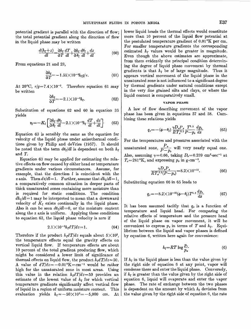
MULTIPHASE FLUIDS IN POROUS MEDIA E37
potential gradient is parallel with the direction of flow; the total potential gradient along the direction of flow in the liquid phase may be written
d(hf+z)Jbhf dT dl 5T dl~
From equations 21 and 23,
(60)
(61)V/jt
At 20°C, T/0=7.4X10-2 . Therefore equation 61 may be written
>\L.(62)
Substitution of equations 62 and 60 in equation 35 yields
, dT . dz~\ //>oxh' + (63)Equation 63 is sensibly the same as the equation for velocity of the liquid phase under anisothermal condi tions given by Philip and deVries (1957). It should be noted that the term ddf/dl is dependent on both h{ and T.
Equation 63 may be applied for estimating the rela tive effects on flow caused by either head or temperature gradients under various circumstances. Assume, for example, that the direction I is coincident with the z axis. Then dzfdl= 1. Further, assume that dhf/dl= 1, a comparatively common situation in deeper parts of thick unsaturated zones containing more moisture than is required for static conditions. The condition dhffdl=l may be interpreted to mean that a downward velocity of Kf exists continually in the liquid phase. Also it can be seen ddf/dl=0, or the moisture content along the z axis is uniform. Applying these conditions to equation 63, the liquid phase velocity is zero if
Therefore if the product h^dT/dz equals about 5X10², the temperature effects equal the gravity effects on vertical liquid flow. If temperature effects are about 10 percent of the total gradient producing flow, which might be considered a lower limit of significance of thermal effects on liquid flow, the product hfdTfdz^5Q. A value of dTjdz= 0.01°K=cm~1 would be rather high for the unsaturated zone in most areas. Using this value in the relation hfdT/dz=5Q provides an estimate of the lowest value of hf for which vertical temperature gradients significantly affect vertical flow of liquid in a region of uniform moisture content. This evaluation yields /&$ « 50 X102= 5,000 cm. At
lower liquid heads the thermal effects would constitute more than 10 percent of the liquid flow potential at the postulated temperature gradient of 0.01 °K per cm. For smaller temperature gradients the corresponding estimated h{ values would be greater in magnitude. Even though the above estimates are approximate, from them evidently the principal condition determin ing the degree of liquid phase movement by thermal gradients is that h^ be of large magnitude. Thus it appears vertical movement of the liquid phase in the unsaturated zone is not influenced to a significant degree by thermal gradients under natural conditions except in the very fine grained silts and clays, or where the liquid content is comparatively small.
VAPOR PHASE
A law of flow describing movement of the vapor phase has been given hi equations 57 and 58. Com bining these relations yields
(65)
For the temperatures and pressures associated with thep unsaturated zone, 75 ° will very nearly equal one.
fPv
Also, assuming 7=0.66, taking Z)0 =0.239 cm^-sec"1 at T0 =281°K, and expressing pv hi g-cm~ 2,
r=8.2X10-n .RT^(P-pv}
Substituting equation 66 in 65 leads to
dx
(66)
(67)
It has been assumed tacitly that qv is a function of temperature and liquid head. For comparing the relative effects of temperature and the pressure head of the liquid phase on vapor movement, it will be convenient to express pv in terms of T and hf. Equi librium between the liquid and vapor phases is defined by equation 6, written here again for convenience:
(6)
If hf in the liquid phase is less than the value given by the right side of equation 6 at any point, vapor will condense there and enter the liquid phase. Conversely, if h{ is greater than the value given by the right side of equation 6, liquid will evaporate and enter the vapor phase. The rate of exchange between the two phases is dependent on the amount by which hf deviates from the value given by the right side of equation 6, the rate
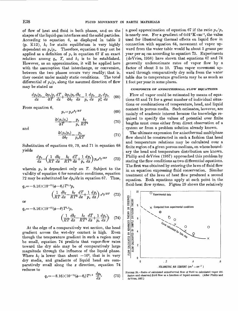
E38 FLUID MOVEMENT IN EARTH MATERIALS
of flow of heat and fluid in both phases, and on the shapes of the liquid-gas interfaces and the solid particles. According to equation 6, as displayed in table 2 (p. E12), h? for static equilibrium is very highly dependent on pv/p0 . Therefore, equation 6 may not be applied as a definition of p, in equation 67 if an exact relation among qv, T, and Af is to be established. However, as an approximation, it will be applied here with the assumption that interchange, or conversion, between the two phases occurs very readily; that is, they coexist under mainly static conditions. The total differential of pjp0 along the assumed direction of flow may be stated as
dx0 dT
dxdk= j_ dp2_pJL dp0 dx O dx i dx
From equation 6,
and
p,=p0e l>t /RT
p0 RT2
PoRT
(69)
(70)
(71)
Substitution of equations 69, 70, and 71 in equation 68 yields
^£_ /J_ dhf ht dT,]_ dpA h /RT ,72x dx \RT dx RT2 dx p0 dx) P°e f U ;
wherein p 0 is dependent only on T. Subject to the validity of equation 6 for nonstatic conditions, equation 72 may be substituted for dpv/dx in equation 67. Thus,
or
/ J_ dhf hf dT ± dp0 h !RT , . \RT dx RT2 dx^o e * ( }
_ . ^ dx )' v J
/ 1 dk __ hf_ dT \RT dx RT2 dx
At the edge of a comparatively wet section, the head gradient across the wet-dry contact is high. Even though the temperature gradient in such a region may be small, equation 74 predicts that vapor-flow rates toward the dry side may be of comparatively large magnitude through the influence of the liquid phase. Where hf is lower than about 10 5, that is in very dry media, and gradients of liquid head are com paratively small along the x direction, equation 74 reduces to
»fo-0r)irL8 *. (75)
a good approximation of equation 67 if the ratio pv/p0 is nearly one. For a gradient of 0.01°K-cm"1, the value used for illustrating thermal effects on liquid flow in connection with equation 64, movement of vapor up ward from the water table would be about 3 grams per year per sq cm according to equation 75. Experiments (deVries, 1958) have shown that equations 67 and 74 generally underestimate rates of vapor flow by a factor of about 3 to 10. Thus vapor movement up ward through comparatively dry soils from the water table due to temperature gradients may be as much as 1 foot per year in some places.
COMPOSITE OF ANISOTHERMAL, FLOW EQUATIONS
Flow of vapor could be estimated by means of equa tions 63 and 74 for a great number of individual situa tions or combinations of temperature, head, and liquid content in porous media. Such estimates, however, are mainly of academic interest because the knowledge re quired to specify the values of potential over finite lengths must come either from direct observation of a system or from a problem solution already known.
The ultimate expression for anisothermal multiphase flow should be constructed in such a fashion that head and temperature relations may be calculated over a finite region of a given porous medium, on whose bound ary the head and temperature distribution are known. Philip and deVries (1957) approached this problem by stating the flow conditions as two differential equations. The first was obtained by entering the laws of fluid flow in an equation expressing fluid conservation. Similar treatment of the laws of heat flow produced a second equation. Both equations apply at each point in the fluid-heat flow system. Figure 29 shows the relatively
\ X Computed from experimental conditions
Experimental data
0 .2 .4 .6
VOLUMETRIC AIR CONTENT (cm 3 -cnr 3 )
FIGURE 29. Ratio of calculated anisothermal flow of fluid to calculated vapor dif fusion and observed fluid flow as a function of liquid content. (After Philip and deVries, 1957.)

MULTIPHASE FLUIDS IN POROUS MEDIA E39
good agreement between observed and calculated rates of fluid flow they obtained.
deVries (1958) discussed an extension of the latter work, including a more comprehensive statement of the interchange between the liquid and vapor phases. Results from the latter theoretical investigation are in need of testing by comparison with observation. Un fortunately, laboratory studies reported in the literature have not included a sufficient number or variety of ob servations and control to permit testing deVries' ap proach adequately at this time.
Miller and Seban (1955) studied the liquid-vapor complex using enthalpy relations and Darcy's law. Equations were derived for computing the amount of vapor flowing as a fraction of the total flow, and for computing the position and length of the transition zone between the single and multiphase flow sections. They used liquid propane flowing horizontally through a porous medium, which was thermally and hydraulically insulated except at the ends. Temperature and pressure were held constant at the uninsulated ends, such that the pores at the inlet end were completely filled with liquified gas, and both liquid and gas phases could exist at the outlet. With such control, at some point between the sample ends, the conditions of temperature and pres sure permitted the liquid to boil and produce vapor. Downstream from that point both the liquid and gas phases were in motion. Both the experimental and theoretical approach taken seem unique to multiphase flow investigations. Predictions made from their theo retical development compared well with laboratory data.
While the heat-flow relation as stated by Philip and deVries (1957) is especially useful for identifying the hydrologic significance of each component part of their equations, the large number of terms contained by their equations greatly complicates the computation of fluid distribution. Use of the enthalpy relations simplifies the expression of heat flow compared with the detailed form required by adding all the components previously discussed. It may be found possible to express aniso- thermal flow as simple functions in terms of bulk energy or matter transport, and thereby reduce the amount and complexity of computation to a minimum. However, it appears premature to consider the form of expression at this time because even the basic understanding of the mechanics of anisothermal flow is far from complete.
CRITERIA FOR HYDRAULIC MODELS OF LIQUID FLOW
As discussed briefly on page E30, calculation of iso thermal movement of liquid over a given region is ex tremely difficult because the basic differential equations defining flow are nonlinear. The hydraulic model, a scaled replica of the prototype, affords in some problems a convenient substitute for calculation. Through proper
model design, systems of comparatively large size can be reproduced in the laboratory on a small scale where liquid movement as a function of time and space may be observed with relative ease. The model should be designed so as to enable one to convert the liquid move ment observed in the model to the dimensions of the prototype system. The chief aim of the model design is to reduce the prototype size to some size convenient for laboratory use and to reduce the time scale of the prototype so the laboratory observations may be con cluded in a comparatively short span of time.
The results obtained in laboratory studies of flow through small samples can be put in terms of flow through prototype systems by applying the rules of model design to the dimensions of the laboratory model. This extends the range over which the laboratory tests can be used as a visual aid to the understanding of un- saturated fluid flow under various prototype conditions. Experimental results on flow in or drainage from ver tical columns (King, 1898; Remson and Fox, 1955; and Youngs, 1957,1958a, b), on centrifuge control of samples (Briggs and McLane, 1910; and Marx, 1956), and on flow in the vicinity of structures (Aronovichi, 1955; and Day and Luthin, 1954) cover a wide spectrum of prototype conditions of size, shape, and conductivity. Model criteria may be applied to such results so as to make the observed data more useful as expressions of prototype activity. A few prototype flow systems have been modeled deliberately and the results have been reported in the literature (Marx, 1956, for example). However, in most of the laboratory investigations re ported in the literature, the scale relations between model and prototype have not been recognized. In many reports of laboratory studies on flow the con clusions developed do not apply to prototype systems because experiment design did not adequately account for scaling factors. Thus a direct comparison between laboratory observations and the flow regime of the much larger prototype cannot be made; and it is difficult, through brief contact with the literature on unsaturated flow, to fully appreciate the validity of general con clusions drawn from small-scale observations.
Leverett and others (1942) described the application of the principles of dimensional analysis to unsaturated liquid flow through porous media. Although attention was focused on modeling the displacement of oil by water, their selection of pertinent variables on which flow depends and their discussion of model design apply equally well to the liquid phase in water-water vapor or water-gas systems where flow is isothermal and pre dominantly in the liquid phase. A more comprehensive treatment including interchange between liquid and gas phases, or anisothermal effects would require inclusion of flow parameters not considered by Leverett and

E40 FLUID MOVEMENT IN EARTH MATERIALS
others. Much of the following has been condensed from three papers (Hubbert, 1937; Leverett and others, 1942; and Marx, 1956) with emphasis on models in which either the porous medium and liquid properties are different from the prototype system or in which the external force field applied on the model is different from gravity.
DIMENSIONAL SIMILITUDE
In ordinary mechanics, motion can be expressed in terms of three fundamental dimensions length, time, and mass. Although in some cases flow in unsaturated porous media may depend on additional characteristics, it is assumed here that the flow is dependent only on those variables that can be defined by combinations of these three dimensions. Temperature and associated thermodynamic relations and most chemical inter actions, for example, are excluded from the liquid flow regime under consideration.
Dimensional similitude between a given characteris tic F in the prototype and F' in the model, as dictated by the principles of dimensional analysis, can be stated in very general form as follows:
z.F'
where L is a characteristic length, t is a unit of time, M is a characteristic unit of mass, and A^B^O are vari ables defining F, all relating to the prototype. The corresponding characteristics and variables of flow in the model are designated by primes.
Equation 76 can be obtained simply by setting a non- dimensional group of variables in the prototype equal to the same group in the model and simplifying the re sult to the form shown. This is a basic requirement for effecting dimensional similitude between flows in the model and prototype (Bridgman, 1931). The ex ponents a, &, * * * / are obtained from the dimensional nature of the functions F or F'. For example, if F represents velocity, then <z=l, &= 1 and c, d, /* * * =0, for by definition velocity is a length divided by time. Each characteristic significant to flow in the model must satisfy equation 76. Variables like F,A,B, and C can all be expressed in terms of the fundamental dimensions Z, t, or M. Thus the model-prototype func tions like A might be related as
A^ A' _/L\ ai /A 6l (M\ <i 7 \L') \t'J \M')
B_ B'~\L'
C~\L'
(M \ t' \M')
M7
and so on. For any given model-prototype system
the ratios YT IT and ~ individually must have theLi , t,
same value as applied to determine each pertinent characteristic of the flow regime. Equation 76 will be more convenient to apply for some purposes than equations like 77, but both forms will be applied in the following for defining the dimensional interrelations among variables of model and prototype flow.
A complete model design is attained only if all the variables on which flow is dependent satisfy the rela tions expressed in equations 76 and 77. For liquid flow the equation of continuity and a form of Darcy's law are believed to adequately define the flow regime at any point. The continuity relation for this case was pre viously given as equation 44:
. dpfflf= "*" (44)
In the form of Darcy's law given as equation 35 the velocity of flow was defined loosely in terms of liquid pressure head only. This statement is adequate where flow occurs in a uniformly accelerated field. However, where force fields of varying magnitude may be im pressed on the flow system, such as may be generated by centrifuging, flow must be defined in its more complete form as a response to energy dissipation as follows :
(78)Ptgtt=-Kt
Equations 44 and 78 together describe the flow relations at every point in an isothermal liquid flow system. Flow is dependent on each of the variables included in these expressions in both model and prototype. Dimen sional similarity between flow at a particular point in the model and the corresponding point in the prototype is assured by appropriate scaling of each characteristic affecting flow by means of equations 76 or 77.
The function F of equation 76 was defined with em phasis on it being of a dimensional nature. This does not preclude the use of equation 76 for showing the model-prototype relation between nondimensional fac tors such as porosity, $, and 0f. According to equa tion 76, if F is nondimensional, F/F'=1. Thus, to maintain dimensional similarity between model and prototype all nondimensional factors must have the same numerical value in both flow systems. Porosity in the prototype must be reproduced in the model, and the volumetric liquid content at each point in the model is the same as the volumetric liquid content at corre sponding points in the prototype. The shape of the

MULTIPHASE FLUIDS IN POROUS MEDIA E41
model can also be expressed in nondimensional form, such as by a group of width to length ratios. There fore the shape of the model is congruent with the shape of the prototype. For example, if the prototype is rectangular, of length A and width B, the model must also be rectangular with a length to width ratio of A/B. This conclusion is reached directly through equations 77. The lengths A and A' are related as A/A'= (L/L') ai. By definition of A, a length to the first power, d=1. Similarly for B and B', B/B'=(L/L') "2, wherein a^= 1, also by definition of B. For dimensional similitude the ratio (L/Lf) must be the same through out the model, as taken along the directions of either length, width, or depth. Thus A/A'=B/B', or A/B=A'/Bf } the same result as stated above.
A composite term showing the interrelation among the variables of flow in equation 78 has been studied by Leverett (1941). He tested the nondimensional "j-iunction":
1/2
(79)
by measuring 8? versus j(df) on a variety of samples and liquids and obtained a relatively good correlation for static equilibrium, thus indicating the hydraulic char acteristics of many types of porous media might be de fined by a single curve. Because the ./-function is nondimensional j(0t)/j'(8t) = l. Following the form of equation 76, the model-prototype relation from equa tion 79 is M»'©*(*rBy definition, Pc Ptghf, and because 0 is nondimen sional, 0/0'= 1. Thus equation 80 may be written
p, gf)\L')\Kf) (81)
wherein the hf/h'^ ratio has been set equal to the length ratio L/L'.
According to equation 78, flow is directly dependent on Kf, which accounts for the characteristics of both fluid and solid. Kf may be related to the specific permeability, K, by the definition:
(82)
where fj, is the liquid viscosity. The model-prototype relation for equation 82 is found to be
(83)
Whereas it is generally recognized that KT $ is an involved function of the porosity, particle-size distribu
tion, antecedent history of flow, and other properties of the porous medium, current practice in flow analysis is to assume that Krf is a unique function of h? or 0f for a given porous medium. Also Kr { is dimensionless and therefore K^/K^i^l. Thus the curve of relative conductivity versus 0f or hf of the porous medium in the model must be identical with the same curve of the porous medium in the prototype. In model design it will not be convenient usually to regulate Kf/Kf directly because this ratio is dependent on a variety of liquid and solid characteristics. Conduc tivity may be regulated by modeling directly in accord ance with its dimensional characteristics as follows:
K' \L' t7 (84)
which is easily derived from equation 77, recognizing that Kf has the dimensions of velocity. Substitution of equation 84 and the relation Krf/K^=l in equation 83 yields
Equation 85 may be put in equation 81, from which
Equations 85 and 86 together are a complete state ment of the dimensional interrelations among the liquid and solid properties of the model-prototype systems of isothermal liquid flow. The nondimen sional interrelations are given completely by
(87)
Correct dimensional scaling of a prototype flow system is attained only if the model and prototype character istics satisfy all three equations, 85, 86, and 87.
STATIONARY MODEL IN EARTH GRAVITY FIELD
As an example of model design by equations 85, 86, and 87, assume that a proposed model is to be observed in the laboratory under the earth gravity field, the same field of force causing flow in the prototype. The model is to remain stationary. Therefore g/g'=l and by definition of the dimensions of the gravitational force equation 76 or 77 yields
-rr] =1
from which
(88)

E42 FLUID MOVEMENT IN EARTH MATERIALS
Applying equation 88 to equations 85 and 86,
.tv ' 1/2
^ ^
K K'
and
Pr
(89)
(90)
Equations 88, 89, and 90 describe the model-prototype relations among the dimensional characteristics of liquid and solid for stationary models. From equation 90 it is clear that the liquid used in the model must have characteristics different from the prototype liquid if the model is of different size than the prototype. Use of a particular liquid in the model determines the specific permeability of the model in accordance with equation 89.
The maximum scale reduction of the prototype length is limited in stationary models partly because the characteristics of practically useful liquids extend through a limited range. Equation 90 implies that the maximum length reduction from prototype size may be obtained by selecting model liquids with lower surface tension and higher viscosities and densities than of the prototype liquid. Consider the use of glycerol for modeling water movement in unsaturated materials. For glycerol at 20°C, T'=63 dynes-cm" 1 , Pf=1.26 g-cm~3, and 1*'= 1,500 centipoises, approxi mately. The corresponding numerical values for water are: r=72, pr =1.00, and ^=1-00. Substituting the required ratios in equation 90 yields
/
V
T \ 5/4
and
£=22.7.
This length ratio and the appropriate ratios of model- prototype liquid characteristics from the above give the ratio of specific permeability from equation 89 as
JK.
from which K'=25QK. The transformation of time effected by the model design for this case is given by
, from which
Therefore it is apparent that the length-scale reduction of 22.Y is accompanied by a reduction in time scale. Using glycerol in the model as specified, 4.7Y days of flow in the prototype is represented by 1 day of flow in the model.
The L/L' ratio could be increased still more by using a more viscous fluid than glycerol or one having a higher density and lower surface tension. This would have the beneficial result of further decreasing the size of the model and of further compressing the model time scale. For example, the viscosity of the glycerol could be in creased greatly by reducing the model temperature appreciably. However, if the L/L' ratio is thus in creased, the K' /K ratio is greatly increased. There is a practical limit within which the K'jK ratio must remain, depending on the value of K in the prototype. Modeling as indicated involves a concurrent decrease in length of the model and increase in pore or grain size of the medium in the model. The number and distribution of pore interconnections and grain contacts must be sufficient at each point in the model so that j'(Q[), d{, and <£' are true representations of the corre sponding functions in the prototype. If the value of K is large and the inflow and outflow lengths are small in the prototype, the grain size required in the model may be of the same order of magnitude as the length of openings on the boundaries of the model flow system. To this extent, length reduction by scaling is limited. The limits of the characteristics of fluids useful for modeling water movement by stationary models are such that length reductions may not exceed a value of about 30 to 1, and the time scale reduction is therefore limited to about 5.5 to 1.
ARTIFICIALLY ACCELERATED MODEL
Marx (1956) obtained equations relating the flow from centrifuged samples to flow from prototype sys tems by analyzing the boundary conditions in each field of flow. The same equations showing the effects of centrifuging on dimensional relations can be obtained directly from equations 85 and 86. If the centrifuged sample is identical with the material of the prototype, and if the liquid is also the same as that flowing in the prototype,
K _ T _ M = Pr=1 ' ' 'K
(91)
Substituting equations 91 in equations 85 and 86, and expressing each result as g/g',
from which
L't>
(93)
Equation 93 can be used in equation 92 for relating the

MULTIPHASE FLUIDS IN POROUS MEDIA E43
time and length scales to the model acceleration, which shows that
'=L and t'= (94)
The advantages to be derived from artificially accelerat ing the model are partly apparent from equations 94. The length and time scales can be greatly reduced by centrifuging. In the conventional test for moisture equivalent (Am. Soc. Testing Materials, 1958), #' = 1,000 <7, and some soils have been centrifuged at g' = 100,000 g in special tests. For the latter, a sample length of 1 cm would be equivalent to a prototype col umn length of about 3,300 feet, and a centrifuging time of 30 minutes would represent a period of 5 X 10⁹ hours, or more than half a million years in the prototype.
Like the stationary model, the artificially accelerated model is also subject to limitations. In order to keep the size of centrifuge equipment within reasonable bounds, the sample size must be kept small of the order of a centimeter in length or diameter. The grain diameter of the medium must therefore be small so the nondimensional characteristics of the centrifuged me dium are adequately modeled. On account of the sample size limitations alone, the grain size diameter should be less than 0.01 cm, preferably much less. Re arrangement of unconsolidated material under stress produced by acceleration may void the use of centrifug ing for accurate model studies. Compression of both consolidated and unconsolidated models under high ac celeration may also cause significant inaccuracies. The influence of rearrangement and compression on flow from centrifuged models cannot now be evaluated be cause very little appears to be known about these factors.
HYDROLOGIC INVESTIGATIONS AND THE UNSATURATED ZONE
NATURE OF HYDBOLOQIC PROBLEMS
The principal goal of most hydrologic studies is to define the distribution of water on and under the earth's surface as a function of time and space. The occur rence of water at any specified place is dependent on the manner in which water is supplied to that locale and on the ease with which the supply may flow away in the form of discharge. Under natural conditions, supply is largely a function of climate, and the form of dis charge is regulated mainly by such factors as topo graphic characteristics, slope-area-discharge relations of the surface waterways, permeability of the soils and deeper rocks, and other factors. Thus in general terms, the distribution of water might be viewed as dependent on either supply and/or environmental factors. In the writer's opinion, this division of factors is the funda
mental basis for the evolution of the greatly differing approaches to the studies of ground- and surface-water distribution. Most surface-water investigations are de signed to define water distribution as a supply charac teristic, relatively independent of environmental condi tions. Results from such studies are often expressed in the form of flow-duration curves which define the probability of obtaining a given yield from a particular locale over a given time. The occurrence of ground water, on the other hand, is so greatly dependent on en vironment that ground-water investigations are almost completely devoted to an interpretation and description of environmental factors alone.
It is not the writer's intent to discredit this differ ence in approach to hydrologic studies, for like other inventions, it has been mothered by necessity. How ever, the hydrologist is facing a period in which water distribution will be influenced more than ever by man's activities. Where man's use of water rearranges water distribution markedly, the climatic factors become rela tively less important in resource evaluation for a given locale, and the environmental factors both natural and manmade become relatively more important. Questions arise concerning ground-water yield from ex tensive dewatering of saturated formations, reduction of rejected recharge by lowered ground-water levels, ef fects of land-management practices on stream flow, operation of multipurpose water systems, return of ir rigation water to ground-water storage, contamination of water supplies by the disposal of waste, that is, sew age from septic systems and from atomic energy plants. These are but a few of a host of problems associated with man's use of water that require attention. As water use is increased, the significance of factors like these to total water availability is expected to increase.
Beyond the common denominator of man's use in the general class of problems characterized above, each is highly dependent on one environmental factor hereto fore given little attention in hydrologic investigations. The solution to all these problems, in quantitative terms, depends upon knowledge of the characteristics of the unsaturated zone. Within the category of en vironmental factors the unsaturated zone to this day remains as a kind of no-man's land viewed from afar by both the ground- and surface-water specialists. Yet with the increasing use of water, the unsaturated zone must be studied by hydrologists because it is a dominant link between ground- and surface-water distribution. Furthermore, the hydrologic questions posed require that the unsaturated zone be considered as an integral part of the hydrologic system.
Even in ground-water investigations where environ mental factors are given greatest weight, the unsatu rated zone usually is treated as a passive component.

E44 FLUID MOVEMENT IN EARTH MATERIALS
As a summary statement to describe his concept of changes in ground-water storage, Meinzer (1923, p. 28) proposed the term "specific yield" and defined it as follows:The specific yield of a rock or soil, with respect to water, is the ratio of (1) the volume of water which, after being saturated, it will yield by gravity to (2) its own volume.
Carrying idealism to an extreme, one might note that the effects of gravity, space, and time are not specified completely, or in detail, in this definition. Thus one might assume that, ideally, it applies to static condi tions in an infinitely long column. This speculation leads to the result that specific yield is simply equal to the porosity. But an idealistic interpretation of Meinzer's definition is not warranted. He wrote (Meinzer, 1923, p. 1-2):
A definition is the expression of a concept by means of language, it should include all that is involved in the concept, but nothing more * * * It has the same significance as the definition of the concept; it is neither more nor less precise * * *
Through the philosophy evident in Meinzer's writings on the subject of specific yield, it is apparent that the concept is not defined by a restricted set of idealized environmental conditions. Eather, he included discus sion of several factors that affect specific yield as observed in the natural state, that is, recharge or dis charge through the land surface, thickness of the un- saturated zone, variations in hydraulic characteristics of the rocks, salinity, and temperature. Thus specific yield relates changes in ground-water level to changes in storage in the field environment. Because the en vironmental conditions regulating changes in liquid content vary with time, field observations of specific yield will in general differ from one another at the same location. Thus tests on small samples designed to measure specific yield in the laboratory are not ade quate unless the field environmental conditions are ac counted for in the analysis of the laboratory tests.
Specific yield, like the flow-duration curve, originates from measurements of the flow system made under a particular set of circumstances not always known in sufficient detail to permit use of the observed value for other prescribed boundary conditions. It represents a resultant of unknown factors. Yet, the conditions that result in a particular value of specific yield as may be observed in the field, contribute equally to the change in storage caused by any set of conditions man's use of water may conceivably impose on the unsaturated zone.
To afford means for predicting hydrologic changes in the unsaturated zone, or the effect of the unsaturated zone on surface and ground water, the unsaturated zone must be defined in terms of those hydraulic char
acteristics that regulate fluid movement through it. Adhering strictly to the principles of flow known from theoretical considerations of multiphase fluids, one might visualize that a complete definition of the unsatu rated zone would require a great amount of detail. However, it is not unrealistic to assume that further study might produce one or a few simple general rela tionships and yet retain all the fundamental concepts of flow. It seems almost imperative that some form of sim plified approach be obtained for analyzing in a practi cal manner the role of the unsaturated zone on water distribution.
PROBLEMS IN DEFINING THE BEHAVIOR OF THE UNSATURATED ZONE
Viewing the flow in the unsaturated zone as a pre dictable response to given stress, it is evident that three basic features of the zone must be defined to make be^ havioral predictions in advance of stress applications. These features are:1. The nature of the fluids and the porous media. Fluid
and media characteristics must be expressed in terms of energy dissipation or energy states result ing from fluid movement or state of fluid occur rence in porous media.
2. The laws of fluid flow which define the relations be tween matter and energy distribution or transfer.
3. The stress to be applied along the boundaries of the region of interest. Included in unsaturated zone investigations for example, might be such factors as position of the water table and rates of change, rates of recharge at the land surface, distribution of temperature and salinity in time and space.
The extent to which flow in the unsaturated zone, and flow to or from the contiguous saturated zone and land surface, can be predicted is dependent on the degree to which all these features may be defined in any given problem. There exists an interdependence among the features listed. As was noted in earlier discussions in this report the laws of anisothermal liquid, vapor, and gas flow are complicated statements of physical activity that are not yet satisfactorily understood. Where the stress applied on the unsaturated zone is such that si multaneous motion of all three fluids must be analyzed, definition of the system is therefore inadequate. Where the nature of the fluids and porous media needs to be investigated in detail by field measurement, again there is difficulty in defining the problem because field meas urement techniques are unequal to the task (Olson and Hoover, 1954). It is evident that the hydrologist's ability to predict flow in the unsaturated zone is limited partly by fundamental deficiencies in the laws of flow and by inadequate field instrumentation. Nevertheless,

MULTIPHASE FLUIDS IN POROUS MEDIA E45
in many hydrologic problems unsaturated flow may be adequately approximated by assuming that the flow is entirely in the liquid phase, and by substituting labora tory tests and analysis for field measurement.
Once the hydrologist has gained an adequate and practical definition of the flow characteristics of the unsaturated zone for a given problem through approxi mation, he faces other barriers that might prevent the successful prediction of flow. Integration of flow re lations expressed in the simplest of forms over a finite region is virtually impossible by the simpler techniques of constructing algebraic analytical equations relating flow to time and space. Further, it does not appear that simple analytical techniques are competent for this purpose. At best the laws of flow are of nonlinear form, systems studied in the field are highly nonhomogeneous, and the boundary conditions are highly variable. How ever, these conditions do not present an impenetrable barrier to the solution of flow problems. It has already been demonstarted that finite-difference techniques, hy draulic models, or electronic analogs may be employed to solve problems of this type satisfactorily. Aside from calculating flow within the unsaturated zone, this methodology may also be applied for computing the boundary conditions attending overland flow and for defining the rate at which water is removed from storage in ground-water reservoirs.
RESEARCH REQUIREMENTS
It is evident from a review of the literature on the occurrence of multiphase fluids that problems of iso thermal flow of the liquid phase in the unsaturated zone can be solved directly by adopting applicable tested theories. However, it appears likely that all so lutions to such problems will be attained only through some form of approximation, the degree of acceptable approximation depending on the nature of the individ ual problem to be solved. The characteristics of the sediments comprising the unsaturated zone are every where variable from place to place. Generally it will not be possible to take all the variations into account in a study of flow because the volume and complexity of the computations required becomes too great, or it is impractical or impossible to measure the variations in sufficient detail. A similar difficulty is had with nearly all flow problems involving natural porous media, and it is resolved mainly by limiting the degree of detail observed to that which will yield a realistic estimate of flow relations, and to that which can be processed with funds made available for the work. Thus, permissible detail is limited mostly by the economic import of the flow problem. Though such limitations tend to regu late the extent to which the hydrologist may delve into
a given flow problem, a discussion of them is beyond the scope of this report. It will suffice here to recognize that such limitations exist, and that the cost of a prob lem solution is dependent on the degree to which the complexities of the flow system are described.
The fundamental question of greater interest now is how the hydrologist might employ multiphase fluid- flow theory so as to treat the unsaturated zone as a dy namic part of the hydrologic cycle. There is great need for developing an understanding of the general man ner in which the unsaturated zone affects flow at the surface and underground. This understanding might be gained most simply by comparing calculated flows in the unsaturated and contiguous zones for a variety of assumed sediment characteristics and boundary condi tions. General relationships obtained in this way should be useful as a guide to the selection of those most significant variables affecting flow and requiring meas urement in the field.
Dewatering by gravity drainage might be cited as an example wherein even a general understanding of the nature of flow in the unsaturated zone would be extremely useful to the hydrologist. Extensive dewa- tering of aquifers by pumping wells takes many months or years. Predictions of the amount of water recover able by dewatering are often based on a value of specific yield observed in pumping tests of short duration from a few hours to a few weeks. Recognizing that de- watering involves downward movement of liquid through the unsaturated zone in response to declining ground-water levels, one realizes that a certain amount of time is needed to reach a stable liquid-content profile above the water table. If the time required is compara tively large, tests of short duration will provide values of specific yield that are perhaps much lower than might be attained over long periods of time. Conse quently, predictions of aquifer yield based on short- term test results may be significantly in error. On the other hand, the results of long term tests may not apply to short term yields. This issue has been clouded ma terially by conclusions stated from laboratory experi mentation. The almost standard illustration begins with completely saturating a long upright column of clean sand, then permitting the saturated column to drain freely from the bottom by gravity flow. The drainage from the column is observed and plot ted as cumulative discharge of water versus time of drainage. As time increases, the rate of change of total discharge becomes small, very small when com pared with the average rate of outflow, even for periods of drainage of only a few hours. Observations of this type are the basis for concluding that most of the drain age occurs almost instantaneously as the water level is
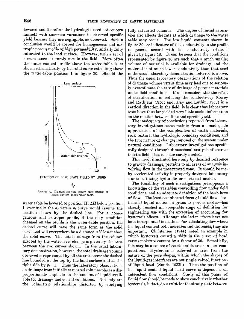
E46 FLUID MOVEMENT IN EARTH MATERIALS
lowered and therefore the hydrologist need not concern himself with timewise variations in observed specific yield because they are negligible, as observed. Such a conclusion would be correct for homogeneous and iso- tropic porous media of high permeability, initially fully saturated to the land surface. However, such a set of circumstances is rarely met in the field. More often the water content profile above the water table is as shown schematically by the solid curve extending above the water-table position I in figure 30. Should the
Land surface
0 1.0
FRACTION OF PORE SPACE FILLED BY LIQUID
'tFIGURE 30. Diagram showing steady state profiles of
liquid content above water table.
water table be lowered to position II, AH below position I, eventually the h? versus 6f curve would assume the location shown by the dashed line. For a homo geneous and isotropic profile, if the only condition changed on the profile is the water-table position, the dashed curve will have the same form as the solid curve and will everywhere be a distance AH lower than the solid curve. The total drainage from the column effected by the water-level change is given by the area between the two curves shown. In the usual labora tory demonstration, however, the total drainage volume observed is represented by all the area above the dashed line bounded at the top by the land surface and at the right side by 0r=l. Thus the laboratory observations on drainage from initially saturated columns places a dis proportionate emphasis on the amount of liquid avail able for drainage under field conditions. Not only are the volumetric relationships distorted by studying
fully saturated columns. The degree of initial satura tion also affects the rate at which drainage to the water table may occur. The low liquid contents shown in figure 30 are indicative of the conductivity in the profile in general accord with the conductivity relations given by figure 18. It can be seen that the conditions represented by figure 30 are such that a much smaller volume of material is available for drainage and the material is of much lower conductivity than that used in the usual laboratory demonstration referred to above. Thus the usual laboratory observations of the relation of drainage volume versus time may lead one to serious ly overestimate the rate of drainage of porous materials under field conditions. If one considers also the effect of stratification in reducing the conductivity (Corey and Rathjens, 1956; and, Day and Luthin, 1953) in a vertical direction in the field, it is clear that laboratory tests have thus far yielded very little useful information on the relation between time and specific yield.
The inadequacy of conclusions reported from labora tory investigations stems mainly from an inadequate appreciation of the complexities of earth materials, rock texture, the hydrologic boundary conditions, and the true nature of changes imposed on the system under natural conditions. Laboratory investigations specifi cally designed through dimensional analysis of charac teristic field situations are sorely needed.
This need, illustrated here only by detailed reference to gravity drainage, pertains to all areas of analysis in volving flow in the unsaturated zone. It should be met by accelerated activity in properly designed laboratory studies utilizing hydraulic or electrical models.
The feasibility of such investigations presupposes a knowledge of the variables controlling flow under field conditions, and an adequate definition of the basic laws of flow. The least complicated form of fluid flow iso thermal liquid motion in granular porous media has already reached an acceptable stage of definition for engineering use with the exception of accounting for hysteresis effects. Although the latter effects have not been incorporated in methods for calculating flow where the liquid content both increases and decreases, they are important. Christensen (1944) noted an example in which hysteresis caused a shift in the curve of head versus moisture content by a factor of 30. Potentially, this may be a source of considerable error in flow com putations. Hysteresis is believed to arise from the nature of the pore shapes, within which the shapes of the liquid-gas interfaces are not single-valued functions of liquid head (Smith, 1933b). Thus the position of the liquid content-liquid head curve is dependent on antecedent flow conditions. Study of this phase of liquid flow should be made to show conclusively whether hysteresis, in fact, does exist for the steady state between

MULTIPHASE FLUIDS IN POROUS MEDIA E47
the liquid and vapor phases. It is conceivable that hysteresis may be a function of nonsteady conditions be tween these two phases, and that laboratory measure ments of liquid head versus liquid content show hystere sis because they were made before steady state is reached. Carman (1952) indicated that the curve of liquid con ductivity versus liquid content shows little if any hys teresis. If this proves to be a valid generalization, the hysteresis function may riot be too troublesome in flow calculations.
A carefully controlled laboratory observation to refine the understanding of hysteresis phenomenon will be difficult. As DeLollis has noted (1952), accurate steady state measurements of the interrelationships among fluid-solid systems are very difficult or impossible to make because such systems are generally self contami nating. Difficulties notwithstanding, a positive ap proach to the definition and use of hysteresis character istics of porous media must be made before the laws of even the simplest form of flow, isothermal liquid motion, are complete.
In a preceding section of this report, it was indicated that where the unsaturated zone is comparatively dry, or is comprised of relatively fine-grained materials, flow must be considered as anisothermal. Fukuda (1955) investigated the removal of liquid from the un saturated zone as it may be effected by air movement through the upper soil layers in response to short and sharp changes in atmospheric pressure. The effect of this type of movement on liquid pressure heads was discussed on pages E21, 22. Fukuda's study showed that fluid transport in vapor form by convection in the gas phase may amount to as much as a foot of water per year. Fluid transport by convection in the gas phase has received such little attention in hydrologic studies that currently it is impossible to clearly evaluate its importance as a mechanism of recharge or discharge in the unsaturated zone. Even though the gas phase velocity in the unsaturated zone has been assumed neg ligible in most studies of anisothermal fluid flow, care ful and detailed field studies should be made so as to gain a more positive identification of its magnitude and effect on liquid content under field situations.
Anisothermal liquid and vapor flow, with the gas phase velocity negligible, has been defined by assem bling the laws of liquid, vapor, and heat flow through simple summation (deVries, 1958; Philip and deVries, 1957). Observed flow rates are in good agreement with the rates predicted from theoretical relationships. Pro visionally, these comparisons are an indication that the theoretical relations may be adequate, on an empirical basis at least. Some of the component laws contained are yet suspect and work is being done to further test
them. Calcium chloride has been used to determine the relation between liquid and vapor movement in re sponse to head or temperature gradients in laboratory tests (Kuzmak and Sereda, 1957b). It was postulated that salt in solution with water would move through a sample only with the liquid phase. Thus by monitor ing the salt content in the outflow from a sample ini tially containing the salty solution, the relative amounts of vapor and liquid reaching the outflow end could be discerned. Conclusions as reported were that, under a temperature gradient movement through the test cell was almost exclusively in the vapor phase, and under a head gradient movement was almost exclusively in the liquid phase. These conclusions should be ques tioned, however, for there remains the problem of ac counting for osmotic pressure effects on the flow system caused by the calcium chloride content (0.0248 g-ml'1 ) of the liquid, and the relative effects on liquid and va por movement caused by either the head or temperature gradient as defined by equations 63 and 74 of this report.
One of the more perplexing problems associated with anisothermal liquid and vapor flow is centered on the disparity between measured vapor flow rates and rates calculated by the gas-diffusion equations. Recent re search has shown that temperature gradients produced locally around grain contacts are much higher than the average gradient imposed across a block of grains. At low moisture contents liquid is concentrated in the vicinity of the grain contacts and the locally high thermal gradients are believed to be more nearly repre sentative of the diffusion potential than are the average gradients. Woodside and Kuzmak (1958) illustrated the local temperature distribution by means of a model of a grain contact area and studied its effect on vapor flow in the vicinity of a pendular ring. Their model gave the temperature distribution in the solid-liquid- vapor system resulting only from heat conduction. Effects on heat distribution from condensation and dis tillation were not included. This model study showed that temperature gradients in the vapor phase locally in the pore may be as much as 6 times the average gradient across the system. However, the model also predicts a flow rate in excess of that postulated from the diffusion concept even for dry media, and this has been largely discounted by experiment (Hanks, 1958). (See also fig. 24.) Philip and deVries (1957) have developed a theoretical model for estimating anisothermal fluid flow through moist materials and obtained good agree ment with observed values. Their theoretical develop ment, however, is still very much in need of substantia tion. The calculated values of fluid flow are dependent on the curves of heat conductivity and heat diffusivity versus moisture content, and these data have been taken

E48 FLUID MOVEMENT IN EARTH MATERIALS
from steady-state heat flow measurements. In past investigations, the heat-flow characteristics of moist porous media have been measured by techniques adapted directly from studies on the physics of solids. The measurement and analytical techniques applied do not account for the recognized mobility of the fluids due to temperature gradients. The excellent work of Jack son and Kirkham (1958) seems to emphasize that water distribution in the pore space is strongly affected by temperature gradients and that this mobility greatly affects the observed heat characteristics. They applied sinusoidal temperature fluctuations of different ampli tudes and periods across soil at various moisture con tents. Apparent diffusivities were plotted as a function of applied period, and, this curve extrapolated to zero period, was supposed to yield estimates of the real thermal diffusivity, relatively unaffected by fluid mobil ity. Effects of the applied periods on apparent diffusiv ity were quite pronounced. The final curves of thermal diffusivity versus moisture content obtained indicate that the thermal characteristics of moist sand observed by steady state techniques may be in error by more than a factor of 10. In another investigation (Kuzmak and Sereda, 1957a) rates of vapor flow across an open space between saturated materials was observed to be nearly three times the rate calculated from the concept of simple vapor diffusion. The authors maintain that this discrepancy might have resulted from inaccurate tem perature measurements. One wonders if more attention might profitably be directed toward estimating the ef fects on diffusion caused by the boundary conditions in the test apparatus.
Uncertainties regarding the mechanism of vapor movement in moist porous media find a parallel in the liquid phase. Generally it has been assumed that move ment of the adsorbed film on the solid surface is negligi
ble where liquid occurrence is in the pendular stage. Evidence to the contrary is mounting. Barrer (1954) has made a theoretical study of the mobility of the ad sorbed stage and has described liquid motion in this stage as a type of surface diffusion.
Carman and Raal (1951) studied the amount of surface diffusion as a function of the amount of fluid adsorbed, and Carman (1952) found that the relation between flow of the adsorbed film and the flow of fluid held by capillarity qualitatively follows the character istics of the adsorption isotherm. Philip (1957b, p. 347) discussed mobility of the adsorbed stage briefly. Flood and others (1952) derived an empirical function relating "surface conductivity" to the amount of fluid adsorbed. The latter involved study of the behavior of several types of fluids adsorbed by porous carbon rods. One of their water adsorption-desorption and conductivity curves are shown in figures 31A and 3IB. Flow was produced by maintaining a constant vapor-pressure difference across the carbon under isothermal conditions at the sample ends. Presumably, movement of adsorbed liquid is most noticeable at liquid contents below the minimum 6$ of the funicular stage because continuity of the thick liquid sections held by capillarity is broken. It is generally accepted that hysteresis effects do not appear at lower 0f values in the pendular and adsorbed stages. The range of 6$ values over which liquid exists in these stages corresponds with those parts of the adsorption-desorption curves which coincide in figure 31 A. According to the simple vapor diffusion theory, if all flow is in the vapor form and the adsorbed film is immobile, the flow rate for this region of Of as plotted in figure 3IB should show a marked decline as 0f increases. This trend is expected because the area available to vapor diffusion decreases and tortuosity increases (Fatt, 1960). However, figure 3lB
40 Vapor pressure 40
0.2 0.4 0.6 .at saturation
WATER CONTENT PER UNIT DRY WEIGHT
FLUID FLOW PER UNIT GRADIENT, IN CUBIC CENTIMETERS PER MINUTE
A BFIGURE 31. Water content and conductivity of carbon plug showing hysteresis. (After Flood and others, 1952.)

MULTIPHASE FLUIDS IN POROUS MEDIA E49
shows the flow rate increasing through all of this region. It therefore seems plausible to attribute much of this movement to mobility in the adsorbed stage. Addi tional studies are needed relating solid surface area and other characteristics to the slope of the conductivity curve at low vapor pressures so as to provide a more positive basis for showing the significance of the move ment of moisture in films. In coarse materials such as the sands, the surface area per unit volume is prob ably so small that film movement is negligible in comparison with vapor movement. But in fine ma terials such as silts and clays, which in many places control the vertical movement of fluid in the unsaturated zone, movement of adsorbed films of moisture may account for most of the fluid movement.
SUMMARY
Evidently a comprehensive statement of the laws of fluid motion in the unsaturated zone has not yet been developed. A few simplified flow models, however, have been devised and tested and are valid for applica tion to restricted ranges of fluid concentration. They may be applied directly for treating the unsaturated zone as a dynamic part of the hydrologic cycle. This is a basic need, especially in studies of water occurrence where man's use of water markedly rearranges distribu tion from the natural state.
The validity of the simplified models of flow is de pendent on whether the assumptions used in developing the model satisfy the environmental conditions. Few suitable comparisons between the simplified flow models and environmental conditions are available in the litera ture. The need for more comprehensive definitions of fluid motion cannot be evaluated successfully until such comparisons are fully realized. It therefore seems that for the present, the principal effort in unsaturated zone studies should be devoted to such comparisons.
The application of the theory of multiphase flow will require the development of computing and modeling techniques for solving the equations of flow, and methods for making field and laboratory measurements of the physical and hydrologic characteristics of earth materials and their environment. Flow problems of the unsaturated zone are not particularly unique, but relatively little has been done to solve equations of the type describing unsaturated flow. Instruments are available for measuring liquid content, density, water salinity, temperature, and other factors in porous media but, in general, only a few have been adapted to meet the demands posed by inaccessability of the unsaturated zone or accuracy requirements of the analytical tech niques.
One of the most important deterrents to the full use of the published results of laboratory and field studies
of multiphase flow is related to incomplete statement of the test conditions or medium characteristics in pub lished reports. This, at any rate, was the writer's ex perience in studying the published test data that was considered potentially useful for elucidating the mech anisms of multiphase flow. One investigator may pre sent a very detailed account of flow rates through "a porous medium," showing clearly the effects of flow caused by a variety of well-controlled and defined en ergy gradients. But his information cannot be com pared, on an adequate base of reference, with another work in which the porous medium was completely de scribed, and only qualitative flow relations were given in summary form even though carefully controlled and complete experiments had been made. It is recognized that publication space is limited, but nonetheless if basic experimental work is to be effective toward solving the problems of multiphase flow, complete published de scriptions of experimental test conditions and results are imperative.
REFERENCES
American Society for Testing Materials, 1958, Standard method of test for centrifuge moisture equivalent of soils, in Pro cedures for testing soils, p. 71-73.
Aronovichi, V. S., 1955, Model study of ring infiltrometer per formance under low initial soil moisture: Soil Sci. Soc. America Proc., v. 19, p. 1-6.
Barrer, B. M., 1954, An examination of the behavior of adsorbed molecules by the flow of gases through microporous media: The physics of particle size analysis, British Jour. Appl. Physics, Supp. 3, p. 49-55.
Baver, L. D., 1956, Soil Physics, 3d ed.: New York, John Wiley and Sons, Inc.
Bradley, R. Stevenson, 1936a (Pt. 2), Polymolecular adsorbed films; Pt. 1, The adsorption of Argon on salt crystals at low temperatures, and the determination of surface fields: Jour. Chem. Soc. (Britain), p. 1467-1474.
1936b (Pt. 2), Polymolecular adsorbed films; Pt. 2, The general theory of the condensation of vapours on finely di vided solids: Jour. Chem. Soc. (Brit.), p. 1799-1804.
Breazeale, E. L., and McGeorge, W. T., 1955, Effect of salinity on the wilting percentage of soil: Soil Sci., v. 80, p. 443-447.
Bridgman, P. W., 1931, Dimensional analysis: Cambridge, Mass., Yale Univ. Press.
Briggs, L. J., and McLane, J. W., 1910, Moisture equivalent de terminations and their application: Am. Soc. Agronomy Proc., v. 2, p. 138-147.
Brunauer, S., Emmett, P. H., and Teller, E., 1938, Adsorption of gases in multimolecular layers: Jour. Am. Chem. Soc., v. 60, p. 309-319.
Buckingham, Edgar, 1907, Studies on the movement of soil mois ture : U.S. Dept. Agriculture Bull. 38, p. 29-61.
Burdine, N. T., 1953, Relative permeability calculations from pore-size distribution data: Am. Inst. Min. Met. Eng. Trans., v. 198, p. 71-78.
Burdine, N. T., Gourmay, L. S., and Reichirtz, P. P., 1950, Pore- size distribution of petroleum rocks: Am. Inst. Min. Met. Eng. Trans., v. 189, p. 195-204.

E50 FLUID MOVEMENT IN EARTH MATERIALS
Campbell, R. B., Bower, C. A., and Richards, L. A., 3948, Change of electrical conductivity with temperature and the relation of osmotic pressure to electrical conductivity and ion con centration for soil extracts: Soil Sci. Soc. America Proc., v. 13, p. 66-09.
Carman, P. C., 1952, Diffusion and flow of gases and vapours through micropores IV. Flow of capillary condensate: Royal Soc. London Proc., v. 211, p. 526-535.
Carman, P. C., and Raal, F. A., 1951, Diffusion and flow of gases and vapours through micropores III. Surface diffusion co efficients and activation energies: Royal Soc. London Proc., v. 209, p. 38-58.
Childs, E. C., and George, N. C., 1948, Soil geometry and soil- water equilibria: Faraday Soc. Discussions no. 3, p. 78-85.
Christensen, H. R., 1944, Permeability-capillary potential curves for three prairie soils: Soil Sci., v. 57, p. 381-390.
Corey, A. T., Rathjens, C. H., 1956, Effect of stratification on relative permeability: Am. Inst. Mining Metall. Engineers Trans., v. 207, p. 358-360.
Crank, J., and Henry, M. E., 1949a, Diffusion in media with vari able properties; Pt. I, The effect of a variable diffusion co efficient on the rates of adsorption and desorption: Faraday Soc. Trans., v. 45, p. 636-650.
1949b, Diffusion in media with variable properties; Pt. II, The effect of a variable diffusion coefficient on the con centration-distance relationship in the nonsteady state: Faraday Soc. Trans., v. 45, p. 1119-1130.
Day, Paul R., and Luthin, James N., 1953, Pressure distribution in layered soils during continuous water flow: Soil Sci. Soc. America Proc., v. 17, p. 87-91.
1954, Sand-model experiments on the distribution ofwater-pressure under an unlined canal: Soil Sci. Soc.America Proc., v. 18, p. 133-136.
DeLollis, N. J., 1952, Note on the displacement pressure methodfor measuring the affinity of liquids for solids: Jour. Phys.Chem., v. 56, p. 193-194.
deVries, D. A., 1958, Simultaneous transfer of heat and moisturein porous media: Am. Geophys. Union Trans., v. 39, p.909-916.
Dorsey, N. E., 1940, Properties of ordinary water substance:Mon. Ser. no. 81, New York, Reinhold Publishing Corp.
Edlefsen, N. E., and Anderson, A. B. C., 1943, Thermodynamicsof soil moisture: Hilgardia, v. 15, no. 2.
Fatt, Irving, 1960, Application of the network model to gasdiffusion in moist porous media: Science, new ser., v. 131,p. 158-159.
Flood, E. A., Tomlinson, R. H., and Leger, A. E., 1952, Theflow of fluids through activated carbon rods: CanadianJour. Chem., v. 30, p. 348-410.
Fox, Robert E., 1957, A proposed method for estimating reduc tion of available moisture in saline soils: Soil Sci., v. 83,p. 449-454.
Fukuda, Hitoshi, 1955, Air and vapor movement in soil due towind gustiness: Soil Sci., v. 79, p. 249-256.
Gardner, Robert, 1955, Relation of temperature to moisture ten sion of soil: Soil Sci., v. 79, p. 257-265.
Gardner, Willard, and Gardner, J. H., 1953, The liquid-vaporinterface in the ideal soil: Soil Sci., v. 76, p. 135-142.
Gardner, W. R., and Mayhugh, M. S., 1958, Solutions and testsof the diffusion equation for the movement of water in soil:Soil Sci. Soc. America Proc., v. 22, p. 197-201.
Hanks, R. J., 1958, Water-vapor transfer in dry soil: Soil Sci.Soc. America Proc., v. 22, p. 392-394.
Harkins, William D., Jura, George, 1944, Surfaces of solids XIII. A vapor adsorption method for the determination of the area of a solid without the assumption of a molecular area, and the areas occupied by nitrogen and other mole cules on the surface of a solid: Jour. Am. Chem. Soc., v. 66, pt. 2, p. 1366-1373.
Hassler, G. L., and Brunner, E., 1945, Measurement of capil lary pressures in small core samples: Am. Inst. Min. Met. Eng. Tech. Pub. 1817.
Herbener, Lt. Wilbur M., 1958, A survey of adsorption phe nomena in the gas-solid phase: Proj. 5534, Rome Air Devel. Center, U.S. Air Force, (U.S. Dept. Commerce, Officers Training School, PB151006).
Horton, R. E., 1933, The role of infiltration in the hydrologic cycle: Am. Geophys. Union Trans., v. 14, p. 446-460.
Hoseh, Mordici, 1937, Heat of wetting of some soil colloids at different moisture contents: Soil Sci., v. 43, p. 257-273.
Hubbert, M. King, 1937, Theory of scale models as applied to the study of geologic structures: Geol. Soc. America Bull., v. 48, p. 1459-1520.
Irmay, S., 1954, On the hydraulic conductivity of unsaturated soils: Am. Geophys. Union Trans., v. 35, p. 463-467.
Jackson, Ray D., and Kirkham, Don, 1958, Method of measure ment of the real thermal diffusivity of moist soil: Soil Sci. Soc. America Proc., v. 22, p. 479-482.
King, F. H., 1898, U.S. Geol. Survey 19th Ann. Rept., Pt. II: Washington, U.S. Govt. Printing Office, p. 59-294.
Klute, A., 1952, Some theoretical aspects of the flow of water in unsaturated soils: Soil Sci. Soc. America Proc., v. 16, p. 144-148.
Krischer, O., and Rohnalter, H., 1940, Warmleitung und dampf diffusion in feuchten gutern: Forschung auf dem Gebiete des Ingenieurwesens 11B, Forchungsheft 402.
Kuzmak, J. M., and Sereda, P. J., 1957a, The mechanism by which water moves through a porous material subjected to a temperature gradient; Pt. I, Introduction of a vapor gap into a saturated system: Soil Sci., v. 84, p. 291-299.
1957b, The mechanism by which water moves through a porous material subjected to a temperature gradient; Pt. II, Salt tracer and streaming potential to detect flow in the liquid phase: Soil Sci., v. 84, p. 419-422.
Lambe, T. W., 1951, Capillary phenomena in cohesionless soils: Am. Soc. Civil Engineers Trans., v. 116, p. 401-432.
Lebedeff, A. F., 1927, Methods of determining the maximum molecular moisture holding capacity of soils: Internat. Cong. Soil Sci., 1st, Proc., v. 1, p. 551-563.
Leverett, M. C., 1941, Capillary behavior in porous solids: Am. Inst. Min. Met Eng. Trans., v. 142, p. 152-169.
Leverett, M. C., and Lewis, W. B., 1941, Steady flow of gas-oil- water mixtures through unconsolidated sands: Am. Inst. Min. Met. Eng. Trans., v. 142, p. 107-116.
Leverett, M. C., Lewis, W. B., and True, M. E., 1942, Dimen sional model studies of oil-field behavior: Am. Inst Min. Met. Eng. Trans., v. 146, p. 175-193.
Marx, J. W., 1956, Determining gravity drainage characteristics on the centrifuge: Am. Inst. Min. Met Eng. Trans., v. 207, p. 88-91.
Meinzer, O. E., 1923, Outline of ground-water hydrology with definitions: U.S. Geol. Survey Water-Supply Paper 494.
Miller, E. E., and Miller, R. D., 1956, Physical theory for capillary flow phenomena: Jour. Appl. Physics, v. 27, p. 324-332.

MULTIPHASE FLUIDS IN POROUS MEDIA E51
Miller. Frank G., and Seban, Ralph A., 1955, The conduction of heat incident to the flow of vaporizing fluids in porous media: Jour. Petroleum Technology, v. 7, p. 45-47, De cember.
Moore, Walter J., 1955, Physical Chemistry, 2d ed.: Inglewood Cliffs, N.J., Prentice-Hall Inc.
Muskat, M., 1946, The flow of homogeneous fluids through porous media : Ann Arbor, Mich., J. W. Edwards, Inc.
Olson, David F., Jr., and Hoover, Marvin D., 1954, Methods of soil-moisture determination under field conditions: U.S. Forest Service, Southeastern Forest Expt. Sta. Paper 38, Asheville, North Carolina, 28 p.
Orchiston, H. D., 1953, Adsorption of water vapor: I. Soils at 25°C : Soil Sci., v. 76, p. 453-465.
Philip, J. R., 1955, Numerical solution of equations of the dif fusion type with diffusivity concentration-dependent: Fara day Soc. Trans., v. 51, p. 885-892.
1957a, Numerical solution of equations of the diffusion type with diff usivity concentration-dependent II: Australian Jour. Physics, v. 10, p. 29-42.
1957b, The theory of infiltration: 1. The infiltration equation and its solution: Soil Sci., v. 83, p. 345-357.
1957c, The theory of infiltration: 2. The profile of infin ity : Soil Sci., v. 83, p. 435-448.
1957d, The theory of infiltration: 3. Moisture profilesand relation to experiment: Soil Sci., v, 84, p. 163-178.
1957e, The theory of infiltration: 4. Sorptivity and alge braic infiltration equation: Soil Sci., v. 84, p. 257-264.
1957f, The theory of infiltration: 5. The influence of the initial moisture content: Soil Sci., v. 84, p. 329-339.
1958a, The theory of infiltration: 6. Effect of water depth over soil: Soil Sci., v. 85, p. 278-286.
1958b, The theory of infiltration: 7. Soil Sci., v. 85, p.333-337.
Philip, J. R., and deVries, D. A., 1957, Moisture movement in porous materials under temperature gradients: Am. Geo- phys. Union Trans., v. 38, p. 222-232, 594.
Pirson, Sylvain J., 1958, Oil reservoir engineering: New York, McGraw-Hill Book Co., Inc.
Purcell, W. R., 1949, Capillary pressures Their measurement using mercury and the calculation of permeability there from : Am. Inst. Min. Met. Eng. Trans., v. 186, p. 39-48.
Quirk, J. P., 1955, Significance of surface areas calculated from water vapor sorption isotherms by use of the B.E.T. equa tion : Soil Sci., v. 80, p. 423-430.
Rapoport, L. A., and Leas, W. J., 1951, Relative permeability to liquid in liquid-gas systems: Am. Inst. Min. Met. Eng. Trans., v. 192, p. 83-98.
Remson, Irwin, and Fox, G. S., 1955, Capillary losses from ground water: Am. Geophys. Union Trans., v. 36, p. 304-310.
Richards, L. A., 1928, The usefulness of capillary potential to soil moisture and plant investigations: Jour. Agr. Research, v. 37, p. 719-742.
1931, Capillary conduction of liquids through porous me diums : Physics, v. 1, p. 318-333.
Richards, L. A., and Fireman, Milton, 1943, Pressure-plate ap paratus for measuring moisture sorption and transmission by soils: Soil Sci., v. 56, p. 395-404.
Richards, Sterling J., and Weeks, Leslie V., 1953, Capillary conductivity values from moisture yield and tension meas urements on soil columns: Soil Sci. Soc. America Proc., v. 17, 206-200.
Ritter, H. L., and Drake, L. C., 1945, Pore-size distribution in
porous materials: Indus. Eng. Chem., Ann. Ed., v. 17,p. 782-786.
Rollins, Ralph L., Spangler, M. G., and Kirkham, Don, 1954,Movement of soil moisture under a thermal gradient: High way Research Board Proc., v. 33, p. 492-508.
Rose, Walter, 1951, Some problems of relative permeabilitymeasurements: World Petroleum Gong. Proc., Sec. 2,p. 446-459.
Scheidegger, Adrian E., 1957, The physics of flow through porousmedia : New York, The McMillan Co.
Smith, W. O., 1933a, Minimum capillary rise in ideal uniformsoil: Physics, v. 4, p. 184-193.
1933b, The final distribution of retained fluid in an ideal uniform soil: Physics, v. 4, p. 425-438.
1943, Thermal transfer of moisture in soils: Am. Geophys. Union Trans., v. 24, p. 511-524.
Smith, W. O., Foote, P. D., and Busang, P. F., 1931, Capillary rise in sands of uniform spherical grains: Physics, v. 1, p. 18-26.
Solvason, K. R., 1955, Moisture in transient heat flow: Heating, Piping, and Air Conditioning, v. 27, p. 137-142.
Southwell, R. V., 1946, Relaxation methods in theoretical physics: London, Oxford Univ. Press.
Stallman, R. W., 1954, Discussion of: "The effect of surface head on infiltration rates based on the performance of ring in- filtrometers and ponds" by Leonard SchifE: Am. Geophys. Union Trans., v. 35, p. 171-173.
Stokes, R. H., and Robinson, R. A., 1949, Standard solutions for humidity control at 25° C: Indus. Eng. Chem., v. 41, pt. 2, p. 2013.
Versluys, J., 1917, Die Kappillaritat der Boden: Inst. Mitt. Bodenk., v. 7, p. 117.
Wenzel, L. K., 1942, Methods for determining permeability of water-bearing materials: U.S. Geol. Survey Water-Supply Paper 887.
Wong, C. M., Hoh, K. C., and Hadley, W. A., (undated), An electrical method of studying moisture migration in a granu lar medium and a discussion of the effect of a temperature gradient on such migration: New York, Columbia Univ., 14 p., 14 figs.
Woodside, W., and Cliffe, J. B., 1959, Heat and moisture trans fer in enclosed systems of two granular materials: Soil Sci., v. 87, p. 75-82.
Woodside, W., and deBruyn, C. M. A., 1959, Heat transfer in a moist clay: Soil Sci., v. 87, p. 166-173.
Woodside W., and Kuzmak, J. M., 1958, Effect of temperature distribution on moisture flow in porous material: Am. Geophys. Union Trans., v. 39, p. 676-680.
Wyckoff, R. D., and Botset, H. G., 1936, The flow of gas-liquid mixtures through unconsolidated sands: Physics, v. 7, p. 325-345.
Wyllie, M. R. J., and Gardner, G. H. F., 1958a, The generalized Kozeny-Carman equation: Its application to problems of multiphase flow in porous media; Pt. I: World Oil, Pro duction Sec., v. 146, p. 121-128.
1958b, The generalized Kozeny-Carman equation: Its ap plication to problems of multiphase flow in porous media; Pt. 2: World Oil, Production Sec., v. 146, p. 210-228.
Youngs, E. G., 1957, Moisture profiles during vertical infiltra tion : Soil Sci., v. 84, p. 283-290.
1958a, Redistribution of moisture in porous materials after infiltration: 1: Soil Sci., v. 86,117-125.
-1958b, Redistribution of moisture in porous materialsafter infiltration: 2: Soil Sci., v. 86, p. 202-207.
