multilevel ground-water monitoring - solinst groundwater instruments
TRANSCRIPT

11Multilevel Ground-Water Monitoring
Murray Einarson
CONTENTSIntroduction . . . . . . . . . . . . . . . . . . . . . . . . . . . . . . . . . . . . . . . . . . . . . . . . . . . . . . . . . . . . . . . 808Why Three-Dimensional Plume Delineation is Necessary . . . . . . . . . . . . . . . . . . . . . . . 812Measurement of Vertical Hydraulic Heads . . . . . . . . . . . . . . . . . . . . . . . . . . . . . . . . . . . . 814One Time Sampling versus Permanent Multilevel Monitoring Devices . . . . . . . . . . . 814Where You Monitor is as Important as How You Monitor . . . . . . . . . . . . . . . . . . . . . . 816Options for Multilevel Ground-Water Monitoring . . . . . . . . . . . . . . . . . . . . . . . . . . . . . 819
Multilevel Sampling within Single-Interval Monitoring Wells . . . . . . . . . . . . . . . . . 819Multiple Diffusion Samplers Installed inside Single-IntervalMonitoring Wells . . . . . . . . . . . . . . . . . . . . . . . . . . . . . . . . . . . . . . . . . . . . . . . . . . . . . . 819
Diffusion Multilevel System . . . . . . . . . . . . . . . . . . . . . . . . . . . . . . . . . . . . . . . . . . . 820Passive Diffusion Bag Samplers . . . . . . . . . . . . . . . . . . . . . . . . . . . . . . . . . . . . . . . 821
Active Collection of Samples from Multiple Depths within a Single-IntervalWell Using Grab Samplers or Depth-Discrete Pumping . . . . . . . . . . . . . . . . . . . 821Grab or Thief Samplers . . . . . . . . . . . . . . . . . . . . . . . . . . . . . . . . . . . . . . . . . . . . . . . 822Collecting Depth-Discrete Samples by Pumping from Different Depths
in Well Screens . . . . . . . . . . . . . . . . . . . . . . . . . . . . . . . . . . . . . . . . . . . . . . . . . . . . 822Nested Wells (Multiple Tubes or Casings in a Single Borehole) . . . . . . . . . . . . . . . . 823
Bundle Wells Installed in Collapsing Sand Formations . . . . . . . . . . . . . . . . . . . . . 824Nested Wells Installed with Seals between Monitored Zones . . . . . . . . . . . . . . . . 824
Well Clusters (One Well per Borehole) . . . . . . . . . . . . . . . . . . . . . . . . . . . . . . . . . . . . . . 829Dedicated Multilevel Ground-Water Monitoring Systems . . . . . . . . . . . . . . . . . . . . . 830
Drilling and Installation Considerations . . . . . . . . . . . . . . . . . . . . . . . . . . . . . . . . . . 833Installations in Open Boreholes . . . . . . . . . . . . . . . . . . . . . . . . . . . . . . . . . . . . . . . . 833Installations in Unconsolidated Sedimentary Deposits . . . . . . . . . . . . . . . . . . . . 833Minimizing Cross-Contamination . . . . . . . . . . . . . . . . . . . . . . . . . . . . . . . . . . . . . . 836Development of Multilevel Wells . . . . . . . . . . . . . . . . . . . . . . . . . . . . . . . . . . . . . . 836
Westbay MP System . . . . . . . . . . . . . . . . . . . . . . . . . . . . . . . . . . . . . . . . . . . . . . . . . . . 837Solinst Waterloo System . . . . . . . . . . . . . . . . . . . . . . . . . . . . . . . . . . . . . . . . . . . . . . . . 839Solinst CMT System . . . . . . . . . . . . . . . . . . . . . . . . . . . . . . . . . . . . . . . . . . . . . . . . . . . . 841Water FLUTe System . . . . . . . . . . . . . . . . . . . . . . . . . . . . . . . . . . . . . . . . . . . . . . . . . . . 843
References . . . . . . . . . . . . . . . . . . . . . . . . . . . . . . . . . . . . . . . . . . . . . . . . . . . . . . . . . . . . . . . . 845
807

Introduction
One of the most important discoveries made during the last four decades of ground-water research is that the distribution of dissolved contaminants in the subsurface isspatially complex, especially in the vertical dimension. This is due to a number offactors, including the labyrinthine distribution of residual contamination in most non-aqueous-phase liquid (NAPL) source zones, geologic heterogeneity, and mixing mechan-isms (e.g., mechanical mixing and molecular diffusion), that are relatively weak in mostground-water flow systems (National Research Council, 1994). This discovery was madepossible by the use of multilevel sampling devices that facilitated the collection of dis-crete ground-water samples from up to 20 different depths in a single borehole(Cherry et al., 1981; MacFarlane et al., 1983; Reinhard et al., 1984; Smith et al., 1987;Robertson et al., 1991; van der Kamp et al., 1994).
Assessment and monitoring of ground-water contamination at nonresearch sites inNorth America began in earnest in the late 1980s following passage of the ResourceConservation and Recovery Act (RCRA) and the Comprehensive EnvironmentalResponse, Compensation, and Liability Act (CERCLA), commonly known as “Super-fund.” At nonresearch sites, however, environmental consultants — following earlyguidance from U.S. EPA and some State regulatory agencies — installed single-intervalmonitoring wells with screen lengths ranging from 10 to 30 ft to collect ground-watersamples. Since then, the use of such wells (referred to in this chapter as “conventional”monitoring wells) to collect ground-water samples for chemical analysis has becomestandard practice in North America. Analysis of samples from single-interval, conven-tional monitoring wells, however, has led to a common misconception by ground-waterpractitioners that contaminant plumes are vertically homogeneous because, lacking datato the contrary, most assume that the concentrations of solutes measured in the samplesare representative of concentrations within the entire portion of the aquifers screenedby the wells.
In the late 1980s, ground-water researchers began to study the biases and apparentplume distortion caused by conventional, single-interval monitoring wells (see Sidebar).The studies show that conventional monitoring wells yield composite samples thatmask the true vertical distribution of dissolved contaminants in the aquifer. Further, thecomposite samples are strongly biased by the position and length of the well screens,the pumping rate during sampling, and ambient vertical flow in the well (see Sidebar).Continued industry reliance on conventional monitoring wells for site assessment andmonitoring has prolonged the misconception that the distribution of dissolved contami-nants in the subsurface is more homogeneous than it really is. This can have seriousconsequences for health risk assessments and the performance of in situ remediationsystems, as discussed later in this chapter.
The bias caused by compositing in monitoring wells is shown conceptually inFigure 11.1. In Figure 11.1a, several monitoring wells are shown. The well labeled “L” isa single-interval well with a relatively long screen. Wells labeled “M” make up a clusterof three wells completed at different depths in the aquifer. Well “N” is a multilevel moni-toring well that yields ground-water samples from seven discrete depths. In Figure 11.1b,the concentrations of a hypothetical dissolved contaminant in the aquifer are depicted in aheavy dashed line. Well “L” (the well with a relatively long screen) yields a sample that is amixture of water containing high concentrations of the contaminant (entering the wellfrom the upper part of the well screen) and water that has lower concentrations of thesolute (entering the well from deeper portions of the aquifer). The sample from well
808 Handbook of Environmental Site Characterization and Ground-Water Monitoring

“L” is therefore a composite that: (1) understates the peak concentrations in the portion ofthe aquifer screened by the upper part of the well and (2) overstates the presumed depth ofdissolved-phase contamination in the aquifer. The cluster of three wells with shorter wellscreens (well cluster “M”) yields samples that more closely reflect the actual distribution ofthe dissolved-phase contaminants in the aquifer than the sample from the single long-screened well. The multilevel well (well “N”) provides samples that most closely resemblethe actual distribution of the dissolved-phase contaminants in the aquifer.
A real-life example of the bias caused by sample compositing can be seen in datacollected from a multilevel monitoring well that was installed in Santa Monica, CA tomonitor a dissolved plume of methyl tert butyl ether (MTBE). The multilevel well waslocated within 20 ft of a pair of 4-in. diameter conventional monitoring wells (WellsMW-14 and MW-16) in order to compare the concentrations of MTBE in water samplescollected from the multilevel well with samples collected from the conventional wells(Einarson and Cherry, 2002). A summary of the stratigraphy and construction of theCMT well and the nearby conventional monitoring wells is shown in Figure 11.3.A graph of MTBE concentrations versus depth for all three wells is shown on the rightof the figure. Comparison of the MTBE concentrations measured in samples from the multi-level well with data from the conventional wells provides an example of contaminantmixing in monitoring wells described earlier. It is clear from the figure that the conven-tional wells yield ground-water samples that are a composite of ground water withinthe vertical interval of the aquifer screened by the wells. Analysis of a sample fromZone 3 of the multilevel well shows that MTBE is present in the aquifer at concentrationsas high as 5300 mg/l. However, the concentration of MTBE measured in samples from the
ML N(a) (b)
N
N M
N
N
NM
LN
N
M
Actual concentration of dissolved solute in aquifer
Screened interval(typ.)
ConcentrationD
epth
FIGURE 11.1Effect of well screen length on sample concentrations. (a) Three types of monitoring well completions – single-zone, long-screen well (well “L”); cluster of three wells completed to different depths (wells “M”); and multilevelwell (well “N”). (b) Heavy dashed line shows actual concentration of a dissolved solute in the aquifer. Single-zone, long-screen well (well “L”) yields a sample that is a mixture of high concentrations of the soluteentering the upper portion of the well screens and low concentrations entering the lower portion of the well.Multilevel monitoring well (well “N”) yields samples that most closely represent the true distribution of thedissolved solute in the aquifer. See text for further discussion. (From John Cherry. With permission.)
Multilevel Ground-Water Monitoring 809

Sample Biases and Cross-Contamination Associated with ConventionalSingle-Interval Monitoring Wells
Several field, laboratory, and modeling studies have been performed in the last 15 yr toevaluate whether ground-water samples collected from conventional, single-intervalmonitoring wells (i.e., wells having a single-screened interval ranging from 10 to 30 ftlong) accurately reflect the concentration of dissolved contaminants in the portion ofthe aquifer screened by the wells (Robbins, 1989; Martin-Hayden et al., 1991; Robbinsand Martin-Hayden, 1991; Gibs et al., 1993; Akindunni et al., 1995; Chiang et al.,1995; Conant Jr. et al., 1995; Church and Granato, 1996; Reilly and Gibs, 1996; Martin-Hayden and Robbins, 1997; Reilly and LeBlanc, 1998; Hutchins and Acree, 2000;Martin-Hayden, 2000a; 2000b; Elci et al., 2001). From these studies, it is clear thatwater samples collected from conventional monitoring wells are actually blended orcomposite samples. If the dissolved contaminants are stratified within the aquifer,which, based on detailed vertical ground-water sampling at several field researchsites, appears to be the rule rather than the exception, compositing in long-screenedwells during sampling results in underestimation of the maximum concentrationspresent in the aquifer. Robbins (1989) calculated that the negative bias caused by in-well blending could be up to an order of magnitude. Gibs et al. (1993) performed afield study and concluded that the contaminant concentration in a vertically averagedsample would be 28% of the maximum concentration in the aquifer. Moreover, if thewells partially penetrate the aquifer, an additional bias is introduced due to groundwater (either clean or contaminated) flowing into the well from above and below thewell screens (Akindunni et al., 1995; Conant Jr. et al., 1995; Chiang et al., 1995).Further, modeling performed by Martin-Hayden and Robbins (1997) showed thatvertical concentration averaging in monitoring wells can result in significant over-prediction of contaminant retardation factors and apparent decay constants.
Other researchers have focused on the biases caused by ambient vertical flow ofground water in wells when they are not being pumped (McIlvride and Rector,1988; Reilly et al., 1989; Church and Granato, 1996; Hutchins and Acree, 2000; Elciet al., 2001; Elci et al., 2003). In areas with vertical hydraulic gradients, installationof a monitoring well may set up a local vertical flow system because of the naturalvertical hydraulic gradient at the well location. The well then acts as a “shortcircuit” along this gradient, with the resulting flow in the wellbore often of sufficientmagnitude to compromise the integrity of any samples collected from the well (Elciet al., 2001). Reilly et al. (1989) concluded that ambient vertical flow renders long-screen wells “almost useless.” They also noted that borehole flow and transport ofcontaminants in long-screen wells may contaminate parts of the aquifer that wouldnot otherwise become contaminated in the absence of a long-screen well. Churchand Granato (1996) concluded that “long-screen wells will fail even in a relativelyideal setting, and therefore, cannot be relied upon for accurate measurements ofwater-table levels, collection of water-quality samples, or fluid-conductancelogging.” Hutchins and Acree (2000) found that ambient vertical flow of less contami-nated ground water into a monitoring well with only 10 ft of well screen caused a sig-nificant negative bias that could not be negated by purging the well prior to sampling.Elci et al. (2001) used a numerical model to simulate ambient vertical flow in a fullyscreened well at the Savannah River Site near Aiken, SC (see Figure 11.2). The sitehas an upward hydraulic gradient, so flow within the well was upward. Tracer trans-port simulations showed how a contaminant located initially in a lower portion of theaquifer (“A” in Figure 11.2) was transported into the upper portion and dilutedthroughout the entire well by inflowing water. Even after full purging, samples
810 Handbook of Environmental Site Characterization and Ground-Water Monitoring
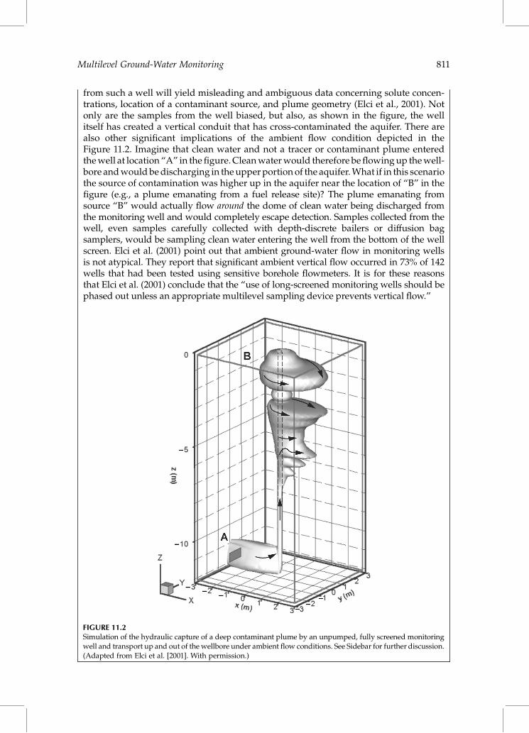
from such a well will yield misleading and ambiguous data concerning solute concen-trations, location of a contaminant source, and plume geometry (Elci et al., 2001). Notonly are the samples from the well biased, but also, as shown in the figure, the wellitself has created a vertical conduit that has cross-contaminated the aquifer. There arealso other significant implications of the ambient flow condition depicted in theFigure 11.2. Imagine that clean water and not a tracer or contaminant plume enteredthe well at location “A” in the figure. Clean water would therefore be flowing up the well-bore and would be discharging in the upper portion of the aquifer. What if in this scenariothe source of contamination was higher up in the aquifer near the location of “B” in thefigure (e.g., a plume emanating from a fuel release site)? The plume emanating fromsource “B” would actually flow around the dome of clean water being discharged fromthe monitoring well and would completely escape detection. Samples collected from thewell, even samples carefully collected with depth-discrete bailers or diffusion bagsamplers, would be sampling clean water entering the well from the bottom of the wellscreen. Elci et al. (2001) point out that ambient ground-water flow in monitoring wellsis not atypical. They report that significant ambient vertical flow occurred in 73% of 142wells that had been tested using sensitive borehole flowmeters. It is for these reasonsthat Elci et al. (2001) conclude that the “use of long-screened monitoring wells should bephased out unless an appropriate multilevel sampling device prevents vertical flow.”
FIGURE 11.2Simulation of the hydraulic capture of a deep contaminant plume by an unpumped, fully screened monitoringwell and transport up and out of the wellbore under ambient flow conditions. See Sidebar for further discussion.(Adapted from Elci et al. [2001]. With permission.)
Multilevel Ground-Water Monitoring 811

conventional wells is much lower (approximately 2300 mg/l) because relatively cleanwater (entering the upper portion of MW-16’s well screen and the lower portion ofMW-14’s well screen) mixes with the water containing high concentrations of MTBEwhen these wells are pumped.
Why Three-Dimensional Plume Delineation is Necessary
Defining the true distribution of dissolved contaminants is arguably the most importantpart of an environmental site assessment. The risk to downgradient receptors is commonlyestimated by calculating the future concentration at the receptor’s location. The calcu-lations are typically performed by estimating (using analytical or numerical equations)the attenuation of the contaminant from some starting concentration near the releasesite. If the starting concentration is underestimated (e.g., by using results obtained from
DE
PT
H (
FE
ET
BG
S)
0
20
40
60
MW-16A
MW-14
80
100
120
140
160
180
200
1
2
3
5
6
7
MTBE
(mg/L)0 1 2 3 4 5 6
MW
-16A
MW
-14
CRW-01Multi-Level Well
DE
PT
H (
FE
ET
BG
S)
0
20
40
60
80
100
120
140
160
180
200
4
FIGURE 11.3Construction details and MTBE concentration profile from a multilevel well plotted next to data from two nearbyconventional monitoring wells, Santa Monica, CA. (Adapted from Einarson and Cherry [2002]. With permission.)
812 Handbook of Environmental Site Characterization and Ground-Water Monitoring

composite samples from long-screened monitoring wells), the risk to the downgradientreceptor (typically a water-supply well) may be underestimated. Similar arguments canbe made for predictions of the risks associated with exposures to vapors emanatingfrom residual contamination near source areas or flowing in shallow contaminantplumes. Vapor migration is dominated by molecular diffusion. Because diffusion isdriven by concentration gradients, underestimating the peak contaminant concentrationsin the subsurface will result in an underestimation of the risk posed to the vapor receptors.However, in other cases, data from long-screened wells can overestimate the risk to vaporreceptors. For example, ground-water recharge at a site may create a layer of clean wateratop a deeper dissolved contaminant plume. The layer of clean water may constitute aneffective diffusion barrier that impedes the upward migration of volatile contaminantsfrom the dissolved plume (Rivett, 1995). The layer of clean ground water overlying thecontaminant plume could only be identified if multilevel ground-water monitoringwells or direct-push (DP) samplers were used. The same layer of clean ground waterwould be completely missed by collecting a composite ground-water sample from asingle-zone well screened over the same depth interval.
Finally, effective remediation systems can be designed only if the concentration anddistribution of the contaminants are accurately defined. This is especially true forpassive in situ remediation technologies, such as permeable reactive barriers (PRBs).PRBs treat contaminants in situ by trapping or degrading the contaminants as they flowthrough them under natural gradient conditions. Complete removal or treatment of thecontaminants requires sufficient residence time within the PRB. In all PRBs, the requisiteresidence time is a function of the concentration of the dissolved contaminants flowingthrough the PRBs. If the peak concentrations of the contaminant in the aquifer are notdefined (e.g., because of sample blending in conventional wells), the PRB may beunder-designed, leading to insufficient residence time and contaminant breakthrough.
It should also be noted that there are likely many instances where PRBs (or wells usedfor pump-and-treat remediation) have been installed deeper than they need to be. Whenconventional single-interval monitoring wells are used to define the maximum depth ofcontamination at a site, it is usually assumed that the contamination extends to theportion of the aquifer corresponding to the bottom of the well screens. Depth-discretemultilevel monitoring may show, however, that the contamination is limited to muchshallower depths. Thus, the PRB may not need to extend to as great a depth as otherwisethought. Because the installation costs of PRBs rise considerably with depth, significantcost savings can be had by accurately defining the vertical extent of contaminationusing multilevel monitoring wells or depth-discrete DP ground-water samplers.
Site assessment technologies and practices have been changing rapidly in the lastdecade. As the biases associated with long-screened monitoring wells have become recog-nized, many practitioners have been installing monitoring wells with shorter well screens.It is not uncommon now to see monitoring wells being installed with screen intervals asshort as 2 or 3 ft. While this is a favorable development as it reduces the samplingbiases associated with long screens, it also increases the likelihood that high-concentrationzones may be missed if only one monitoring well is installed at a particular location. Infact, depending on the depth of the monitoring wells, the contamination can sometimesbe missed altogether (e.g., if the well screens are positioned too high and yield samplesof clean water above a diving plume). Consequently, one short-screened monitoringwell per location is not sufficient to define the vertical extent of dissolved contamination.Depth-discrete sampling devices should be installed at several depths at each location toaccurately map the vertical extent of dissolved contamination. Sampling devices shouldalso be installed to depths where they extend beneath dissolved plumes, that is, where
Multilevel Ground-Water Monitoring 813

the deepest samples no longer detect contamination, or detect it at concentrations that arebelow a particular threshold value.
Measurement of Vertical Hydraulic Heads
The foregoing discussion focused on the importance of accurately mapping contaminantconcentrations in three dimensions. Depth-discrete measurement of hydraulic pressures(heads) is also a necessary part of environmental site assessments. Mapping the hydraulichead distribution in three dimensions allows site investigators to make accurate pre-dictions about the movement and future location of dissolved contaminants. Verticalhydraulic gradients are present at most sites, and the magnitudes of vertical gradientsoften exceed horizontal hydraulic gradients. Upward hydraulic gradients occur inground-water discharge areas; conversely, downward hydraulic gradients exist whereground-water recharge occurs, and can be exacerbated by pumping of nearby remediationand water-supply wells. Defining the vertical hydraulic head distribution at a contami-nated site is an essential part of developing the site conceptual model, and is most oftendepicted using flow nets or three-dimensional ground-water flow models.
Hydraulic heads are determined by measuring the depth-to-water in a piezometer orshort-screened well and subtracting the distance from a known datum (in NorthAmerica, typically the top-of-casing elevation referenced to feet above mean sea level).Hydraulic pressures can also be monitored continuously using electronic pressuretransducers. Pressure transducers as small as 0.39 in. in outside diameter now exist(e.g., Druck Model PDCR 35/D) for use in small-diameter wells and piezometers. If thefocus of a particular study is solely on measuring hydraulic heads and not collectingground-water samples, the pressure transducers can be buried directly to providesingle- or multiple-depth hydraulic head data.
Definition of vertical hydraulic gradients is also necessary to judge whether or notambient vertical flow of ground water is likely occurring in conventional single-intervalmonitoring wells at a particular site. As discussed in the Sidebar, ambient vertical flowof ground water may occur in monitoring wells and other long-screened wells (e.g., reme-diation wells or water-supply wells) whenever (1) vertical hydraulic gradients exist in theaquifer and (2) the wells are not being pumped. Ambient vertical ground-water flow inwells can redistribute dissolved solutes in the subsurface, which can result in cross-contamination of the aquifer and chemically biased samples being collected from thewells. If no vertical hydraulic gradients exist in the portion of the aquifer screened in aparticular well, however, ground-water flow can be assumed to be horizontal throughthe well and vertical flow and redistribution of contaminants may not be a problem. Ifthere is reason to believe that ground water flows horizontally through the well, thewell can sometimes be sampled in a way that sheds light on the natural vertical distri-bution of dissolved contaminants in the portion of the aquifer screened by the monitoringwell. A discussion of techniques that can be used to collect depth-discrete samples fromsingle-interval monitoring wells is presented later in this chapter.
One Time Sampling versus Permanent Multilevel Monitoring Devices
There has been a growing trend in the last decade to collect one-time ground-watersamples at sites underlain by unconsolidated sedimentary deposits using single-interval
814 Handbook of Environmental Site Characterization and Ground-Water Monitoring

direct-push (DP) samplers such as the HydropunchTM, BAT sampler, and other DPground-water sampling tools generically referred to as “sealed-screen samplers”(U.S. EPA, 1997). These tools allow site investigators to collect ground-water samplesfrom discrete depths without having to install permanent monitoring wells. Most of thetools are, however, designed to collect samples from single depths. If samples aredesired from multiple zones, the tools usually must be retrieved, emptied of their contents,cleaned, and re-advanced to the next sampling depth. Thus, obtaining a vertical profile ofcontaminant concentrations from many depths can be a time-consuming process withmost DP ground-water sampling tools. Another tool, the Waterloo Ground-Water Profiler,allows for the collection of discrete ground-water samples from multiple depths withouthaving to retrieve and re-deploy the sampling tool between different depths (Pitkin et al.,1999). A similar tool, the Cone-SipperTM is typically used with cone penetrometer testingrigs. Another comparable tool, the Geoprobe Ground-Water Profiler, is also available. Allthese DP ground-water sampling tools are described in detail in Chapter 6.
One-time DP ground-water sampling tools have some advantages over permanentmultilevel-monitoring wells. First, it is generally faster to collect depth-discrete ground-water samples using DP sampling tools than to install, develop, and sample permanentmultilevel ground-water monitoring wells. Secondly, many site owners dislike having per-manent or semipermanent monitoring devices installed on their properties. The wellsmust be protected during site demolition and reconstruction activities, tracked throughall property transfers, and then decommissioned when they are no longer needed. Also,many responsible parties (RPs) fear that if they have permanent monitoring wells ontheir property, the regulatory agency overseeing the work will require them to monitorthe wells for an indeterminate and possibly protracted period of time.
DP ground-water sampling tools, however, often do not tell the whole story. Forexample, they do not provide information about the vertical hydraulic head distributionat a particular site. Also, one of their main advantages — the fact that they are usedto collect one-time samples — is a drawback at many sites. Monitoring a plume overtime with DP sampling equipment requires remobilization of the DP contractor andre-advancement of the DP sampling tools each time another round of samples isdesired. This becomes costly if long-term ground-water monitoring is needed. Also, thesamples are collected with driven probes and the resulting probe holes are usuallygrouted after the last sample has been collected. It is therefore not possible to obtainsamples from exactly the same points in the aquifer at a later date. Consequently, exclusiveuse of DP ground-water sampling tools is generally not cost-effective at sites whereongoing ground-water monitoring is needed.
So, when and where should permanent multilevel ground-water monitoring systems beinstalled? First, they should be installed whenever and wherever it is necessary to deter-mine the vertical hydraulic head distribution. Because measuring vertical hydraulic headsis fundamental in the development of a site conceptual model, installation of multilevelmonitoring wells or piezometers that allow for measurement of hydraulic heads atmultiple depths is needed at virtually every contaminated site. Measuring temporalchanges in hydraulic heads at a site is particularly important in understanding theground-water flow system, mixing mechanisms, and contaminant distribution. Secondly,any time that ongoing, long-term multilevel water quality monitoring is needed, perma-nent multilevel ground-water monitoring devices should be installed. Considering thatongoing ground-water monitoring (of hydraulic heads and chemistry) is needed andrequired at most contaminated sites, permanent multilevel monitoring devices shouldplay an important role at most sites. For example, long-term ground-water monitoringis often necessary to verify the effectiveness of active remediation. At other sites, time-series samples may need to be collected to document suspected seasonal fluctuations in
Multilevel Ground-Water Monitoring 815

the concentration or flux of contaminants emanating from a residual NAPL source zone.And, of course, long-term multilevel monitoring is necessary at sites where monitorednatural attenuation is the selected remediation method (see Chapter 9). Permanent multi-level monitoring wells should therefore be utilized at most contaminated sites.
Careful planning should be undertaken to select the optimal locations and depths forthe multilevel devices. In unconsolidated sedimentary deposits, it is usually good practiceto first define the general location and depth of the dissolved contaminant plume using DPground-water sampling tools. Then, multilevel monitoring devices can be installed at thelocations and depths that provide the maximum information.
This chapter focuses on permanent multilevel monitoring devices, and Chapter 6presents a discussion of DP methods for collecting one-time samples. Both are importanttechnologies used to characterize contaminated sites in three dimensions.
Where You Monitor is as Important as How You Monitor
The locations of ground-water monitoring wells installed at contaminated sites in theUnited States have historically been selected in order to provide data used to constructplume maps. Conventional plume maps are two-dimensional, plan-view contour mapsof contaminant concentrations obtained from laboratory analyses of ground-watersamples collected from monitoring wells. Unfortunately, such maps rarely provide anaccurate depiction of the true three-dimensional contaminant distribution due to severalfactors. These include: (1) the complexity of most dissolved plumes of contaminants; (2)the wide spacing of most monitoring well networks relative to the high-strength plumecores that are often thin and narrow; and (3) variations in concentrations in samplesfrom the wells caused by differences in well depths, screened intervals, and pumpingrates (see Sidebar for a discussion of biases associated with conventional monitoringwells).
Ground-water researchers have utilized high-resolution ground-water samplingnetworks to characterize dissolved plumes at both controlled and accidental releasesites in unconsolidated aquifers. A particularly useful approach has utilized transects ofclosely spaced multilevel monitoring wells or DP sampling points oriented perpendicularto the plume axes (Semprini et al., 1995; Borden et al., 1997; Devlin et al., 2001; Einarsonand Mackay, 2001; Kao and Wang, 2001; Newell et al., 2003; Guilbeault et al., 2005)(Figure 11.4). The wells or sampling points are often spaced 20 ft (or less) apart horizon-tally and facilitate the collection of discrete ground-water samples from multipledepths. The optimal vertical spacing of monitoring points in a sampling transect is a func-tion of many factors (e.g., the purpose of the monitoring, the type of contamination, thenature and geometry of the source zone, subsurface geology, distance from the contami-nant source, etc.) and is the subject of ongoing research (e.g., see Guilbeault et al., 2005).A minimum of one transect is installed downgradient from the source zone to definethe strength and temporal variability of the contaminant source, or to assess the effective-ness of remediation efforts. Multiple sampling transects are used to evaluate the naturalattenuation of contaminants (see U.S. EPA, 1998; Chapter 9 of this book). Recent advancesin monitoring technologies described in this and other chapters have made these samplingtechnologies accessible to environmental consultants and cost-effective for use at non-research sites.
Transects of multilevel wells are superior to monitoring networks comprised of spatiallydistributed conventional monitoring wells for several reasons. First and foremost, thedense grid or “fence” of sampling points makes it far more likely to detect and accurately
816 Handbook of Environmental Site Characterization and Ground-Water Monitoring
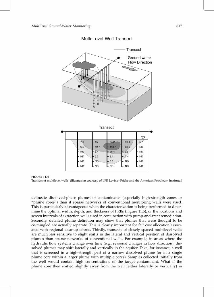
delineate dissolved-phase plumes of contaminants (especially high-strength zones or“plume cores”) than if sparse networks of conventional monitoring wells were used.This is particularly advantageous when the characterization is being performed to deter-mine the optimal width, depth, and thickness of PRBs (Figure 11.5), or the locations andscreen intervals of extraction wells used in conjunction with pump-and-treat remediation.Secondly, detailed plume definition may show that plumes that were thought to beco-mingled are actually separate. This is clearly important for fair cost allocation associ-ated with regional cleanup efforts. Thirdly, transects of closely spaced multilevel wellsare much less sensitive to slight shifts in the lateral and vertical position of dissolvedplumes than sparse networks of conventional wells. For example, in areas where thehydraulic flow systems change over time (e.g., seasonal changes in flow direction), dis-solved plumes may shift laterally and vertically in the aquifer. Take, for instance, a wellthat is screened in a high-strength part of a narrow dissolved plume (or in a singleplume core within a larger plume with multiple cores). Samples collected initially fromthe well would contain high concentrations of the target contaminant. What if theplume core then shifted slightly away from the well (either laterally or vertically) in
Ground waterFlow Direction
Transect
Transect
7.0
6.5
ND
ND
ND
ND
15
40.7
8.4
5.2
ND
ND
54.2
118.7
28.4
9.1
6.3
ND
90.4
62.8
22
7.4
ND
ND
5.7
ND
ND
ND
ND
ND
Multi-Level Well Transect
FIGURE 11.4Transect of multilevel wells. (Illustration courtesy of LFR Levine–Fricke and the American Petroleum Institute.)
Multilevel Ground-Water Monitoring 817

response to a gradual change in lateral or vertical ground-water flow direction? Samplestaken over time from the well would contain progressively lower concentrations of thetarget contaminant simply because the well is sampling lower concentration parts of thesame dissolved plume over time. A plot of sampling results for the well would showdeclining concentrations over time. This trend could logically (but incorrectly) be attribu-ted to source depletion or natural biodegradation. If, on the other hand, the same plumewas monitored with a dense network of multilevel wells arranged in a transect across theplume, lateral and vertical shifts in the plume location could be easily recognized. Shifts inthe position of the plume are obvious if the data are contoured in a vertical cross-sectiondrawn across the plume (i.e., along the transect) as shown in Figure 11.5. Finally, samplingtransects facilitate the calculation of the rate of contaminant migration, referred to as con-taminant mass discharge or total mass flux. Feenstra et al. (1996) defined the plume massdischarge as the amount of contaminant mass migrating through cross-sections of theaquifer orthogonal to ground-water flow per unit of time. Contaminant mass dischargeis a powerful site characterization parameter that, at some sites, may allow site investi-gators to predict the potential impact a plume may have if it were to be captured by adowngradient water supply well (Einarson and Mackay, 2001). Monitoring changes incontaminant mass discharge along the flow path has also been advocated as a way toperform more quantitative evaluations of natural attenuation (U.S. EPA, 1998). Character-izing dissolved plumes on the basis of contaminant mass discharge, therefore, allows siteowners and regulators to focus cleanup efforts on the sites that pose the most significantthreat to downgradient receptors (Feenstra et al., 1996; U.S. EPA, 1998; Einarson andMackay, 2001; Newell et al., 2003).
The above discussion notwithstanding, there are times when individual multilevelwells or individual clusters of monitoring wells distributed more broadly over a site areappropriate. For example, individual multilevel wells or well clusters may be areally dis-tributed at a site to provide information regarding the three-dimensional distribution ofhydraulic head. Definition of the hydraulic head in three dimensions is needed to under-stand the ground-water flow system, calibrate numerical models, and estimate the prob-able location and trajectory of a dissolved plume prior to installing detailed samplingtransects.
Groundwater Flow
FEET
200
A
A'
TreatmentGate
SheetPiling
ControlGate
Multi-LevelWell (typ.)
MonitoringWell (typ.)
>100,000 g/L>100 g/L
DE
PT
H -
FE
ET
FEET
100
0
20
15
10
5
0
20
15
10
5
>1,000 g/L >10,000 g/L
10
ND
ND
ND
ND
32
31ND
43
63
27
ND
ND
ND
8
42
25
34
85
153
186
593
94,430
96,430
2,560
NA
2,409
2,556
31,430
210,100
241,700
129,200
324
156
476
17,280
61,980
42,490
80
237
107
120
2,805
34,860
2,246
NA
469
573
ND
145
11,100
294
37 ND
ND
ND
376
ND
ND
ND
ND
ND
ND
16
50
24
ND
9
13
ND
A A'PZ-5PZ-6PZ-7PZ-8PZ-9PZ-10PZ-11PZ-12PZ-13PZ-14N
FIGURE 11.5Contours of total chlorinated VOC concentrations along a sampling transect installed upgradient from a funnel-and-gate PRB, Alameda Naval Air Station, CA. (From Einarson and Cherry [2002]. With permission.)
818 Handbook of Environmental Site Characterization and Ground-Water Monitoring

Options for Multilevel Ground-Water Monitoring
More options and technologies exist now than ever before for measuring hydraulic headsand collecting discrete ground-water samples from multiple depths at contaminatedsites. Technologies for multilevel ground-water monitoring include nests of wellsinstalled in single boreholes and clusters of wells completed to different depths. Severalspecialized multilevel monitoring systems are also commercially available. These technol-ogies are described in the following sections. Also, it may be possible in some cases to obtaininformation regarding the vertical distribution of dissolved contamination by carefullycollecting depth-discrete samples from within conventional single-interval monitoringwells. The next section begins with a discussion of techniques for performing depth-discretesampling in conventional single-interval monitoring wells and explains when thosetechniques can and cannot be relied upon to yield data that accurately depict theconcentrations and distribution of contaminants in the portion of the aquifer screened bythe wells.
Multilevel Sampling within Single-Interval Monitoring Wells
In recent years there has been a growing trend toward measuring vertical contaminant“profiles” within conventional single-interval wells. In some cases, it may be possible tocollect multidepth ground-water samples from single-interval monitoring wells thatshed light on the vertical distribution of contaminants in an aquifer. However, as dis-cussed, this is not necessarily a simple task and conventional sampling equipment andapproaches often do not yield satisfactory results. New technologies such as passivediffusion samplers may yield better results but they can easily be misapplied, resultingin data that can be misinterpreted.
Multiple Diffusion Samplers Installed inside Single-Interval Monitoring Wells
A thorough discussion of passive diffusion samplers is presented in Chapter 15. The infor-mation in this section therefore augments the material presented in Chapter 15, specifi-cally as it relates to the placement of multiple diffusion samplers in a single monitoringwell in an attempt to gain information regarding the vertical distribution of contaminantsin the subsurface. The first step in this effort consists of installing diffusion samplers atmultiple depths in the screened interval of a monitoring well. The diffusion samplersare made of either dialysis cells or polyethylene bags (further discussion of each ofthese types of samplers is presented). The sample bags or dialysis cells contain deionized,organic-free water, which is physically isolated from ground water in the monitoring wellby a thin sheet or membrane of polyethylene, or, in the case of the dialysis chambersampler, a cellulose membrane. In theory, dissolved contaminants flowing through thewell under natural flow conditions diffuse through the membrane and into the waterinside the polyethylene bags or dialysis cells. The rate of diffusion is controlled byFick’s law, which incorporates both the diffusion coefficient of the contaminant throughthe membrane material and the concentration gradient. The samplers are left in thewell for a period of up to several weeks and then removed. Samples of the water withinthe sample bags or dialysis cells are collected and analyzed for the contaminants ofinterest.
Multilevel Ground-Water Monitoring 819

As discussed in Chapter 15, several factors affect the performance of diffusion samplers.These include:
. The target analyte. For example, hydrophobic organic compounds like halo-genated ethenes and ethanes and aromatic hydrocarbons rapidly diffuse throughpolyethylene. However, hydrophilic compounds like MTBE and most chargedinorganic solutes do not.
. The exposure period. The samplers must remain in the well until the concentrationsof the target compounds in the polyethylene bags or dialysis cells have equili-brated with the concentrations in the ground water. Because molecular diffusionis a function of compound-specific diffusion coefficients and concentration gradi-ents, the exposure period required to reach equilibration varies for differenttarget compounds and different sites (because dissolved concentrations inground water differ between sites and even between the depths of the differentsample bags or containers in the same well).
. Well construction. It is assumed that ground water flows unobstructed through thewell under ambient flow conditions. This may not be the case for wells that arenot in good hydraulic connection with the borehole. Poor hydraulic connectionmay occur due to smearing of clays on the borehole wall during drilling, compac-tion of displaced soil (in the case of DP well installation), or inadequate welldevelopment.
There is an additional factor that must be considered when multiple diffusion samplersare placed inside single-interval monitoring wells in an effort to define the vertical distri-bution and extent of contamination in an aquifer. The factor is the assumption that groundwater is flowing horizontally through the well. If there are vertical hydraulic gradients inthe aquifer (even small ones), there may be ambient vertical flow of ground water in themonitoring well (see Sidebar). In that case, the multidepth diffusion samplers will come incontact with ground water flowing both horizontally and vertically within the well andnot ground water flowing solely horizontally in the aquifer at the depth where the sam-plers are placed. Samples collected from the passive samplers may therefore accuratelyreflect the concentrations of the solute of interest in the well at the depths of the samplers,but they would not reflect the actual distribution of contaminants in the aquifer at thesedepths. The resulting data may therefore be ambiguous and misleading. To avoid this,the use of multiple diffusive samplers placed in a single well screen to obtain depth-dis-crete samples should be done only in aquifers where ground water is known to be flowinghorizontally. Before diffusion sampling devices are installed in the well, site data should bereviewed to ensure that there are no vertical gradients in the formation. As discussedearlier, this can be done by examining vertical head data from multilevel wells or well clus-ters. Alternatively, borehole flowmeter surveys can sometimes be performed in the wellprior to installing the samplers to directly measure whether or not ambient vertical flowof ground water is occurring in the well.
Diffusion Multilevel System
The diffusion multilevel system (DMLS) was the first diffusion sampler designed to collectmultidepth samples from single-interval monitoring wells. Developed by researchers atthe Weizmann Institute of Science in Israel in the 1980s, the DMLS utilizes multiple20 ml dialysis chambers positioned at different depths in the well to collect samples con-taining dissolved solutes that flow through the monitoring well under ambient conditions(Ronen et al., 1987). Deionized water is placed in the chambers prior to insertion of the
820 Handbook of Environmental Site Characterization and Ground-Water Monitoring

DMLS into the well. Solutes in the ground water flowing through the well diffuse into thedialysis chambers. After a few weeks, the DMLS is removed from the well and samplesfrom the various chambers are collected and analyzed. The DMLS can be used to collectsamples containing a variety of inorganic and organic compounds, including chloride,nitrate, sulfate, dissolved oxygen, tetrachloroethylene, and 1,1,1-trichloroethane. Rubberor Viton washers are placed between the various dialysis chambers to reduce or eliminatevertical flow of ground water within the well. More detailed descriptions of the develop-ment and testing of the DMLS are presented in Ronen et al. (1987). An evaluation ofmultidepth ground-water sampling that included the DMLS is presented in Puls andPaul (1997).
The system became commercially available in the U.S. when the patent rights wereacquired by Johnson Well Products, Inc. Johnson sold the DMLS worldwide between1994 and 1998, but discontinued its sale of the DMLS in 1998 when Johnson was acquiredby the Weatherford Company. Ownership of the DMLS reverted to the MarganCorporation, an Israeli company with offices in the U.S. Information regarding theavailability of the DMLS can be obtained by contacting the Margan Corporation(www.margancorporation.com).
Passive Diffusion Bag Samplers
As discussed in Chapter 15, diffusion bags made of polyethylene have recently becomeavailable for passive sampling of dissolved volatile organic compounds (VOCs). Anearly application of the bags was to delineate the location of a VOC plume dischargingto surface water (Vroblesky et al., 1996). Passive diffusion bag (PDB) samplers have sub-sequently been used to collect ground-water samples from monitoring wells (Vrobleskyand Hyde, 1997). One of the claimed advantages of using PDB samplers for collectingground-water samples from monitoring wells is that there is essentially no disruptionof the flow in the well during sample collection, because no pumping occurs. There is,of course, disruption and mixing of water in the well when the PDB samplers are beinginserted into the well. But, the mixed water in the well is usually flushed away bynatural flow through the well during the week or two that the PDB samplers are left toequilibrate in the monitoring well.
Several PDB samplers can be tied together and suspended in a monitoring well to obtaininformation regarding the stratification of contaminants in the well (Vroblesky and Hyde,1997). While this is appealing in concept, the data must be interpreted with the awarenessthat ambient vertical flow in the well may have created a vertical distribution of the targetVOCs in the well that differs significantly from that which exists in the aquifer(see Sidebar). Consequently, the results may be misleading and can result in either under-estimating or overestimating the risks to potential receptors and improper remediationsystem design.
Active Collection of Samples from Multiple Depths within a Single-IntervalWell Using Grab Samplers or Depth-Discrete Pumping
The earlier discussion describes passive methods of collecting depth-discrete samplesfrom monitoring wells using PDB samplers. There are also “active” methods for collectingground-water samples from various depths in a single-interval monitoring well. Theseinclude grab or “thief” samplers (e.g., pressurized bailers, the Kabis Water SamplerTM,the HydrasleeveTM) and pumping methods. Like PDB samplers, however, these activesampling methods simply yield samples from multiple depths in the well, which mayor may not represent the distribution of the target solutes in the aquifer due to possibleambient vertical flow of ground water in the well as discussed earlier.
Multilevel Ground-Water Monitoring 821
Grab or Thief Samplers
Grab or “thief” samplers (e.g., the Discrete Interval SamplerTM, Kabis Water Sampler,Hydrasleeve, Pneumo-BailerTM, etc.) are nonpumping devices used to collect depth-discretesamples of ground water from a well. The devices are lowered into a well to a target depthand then actuated to collect a ground-water sample from specific depth. In the case of theDiscrete Interval SamplerTM, the sampler is pressurized at the ground surface, which seatsa check valve in the sampler, thereby preventing water from entering it. When thesampler is at the target depth, the pressure is released. This opens the check valve andallows ground water from the target depth to flow into the sampler. The sampler is thenre-pressurized, thereby preventing the introduction of ground water from other intervalsinto the sampler while it is being retrieved. The procedure is repeated to collect samplesfrom other depths in the well. For more information about the samplers, the reader is referredto an evaluation of five discrete interval ground-water sampling devices performed by theU.S. Army Corps of Engineers (Parker and Clark, 2002) and to Chapter 15 of this book.Grab or thief samplers are also used to collect depth-discrete samples from wells (both moni-toring wells and water-supply wells) that are being pumped as the samples are beingcollected. Collecting depth-discrete samples from wells as they are being pumped hasbeen shown to be a useful technique to determine where contaminants are entering thewells (Foote et al., 1998; Jansen, 1998; Gossell et al., 1999; Sukop, 2000).
Using grab or thief samplers to collect depth-discrete samples under non-pumping con-ditions may sometimes yield ambiguous results. First, ambient vertical flow in the wellmay have redistributed contaminants in the well prior to sample collection (see Sidebarand earlier discussion). Secondly, the process of lowering the sampler to the targetdepth(s) may cause considerable mixing in the well. Thus, the sample collected may bea mixture of water from other zones, even if the contaminant distribution in the wellclosely matched that in the aquifer prior to lowering the sampler into the well. Also, low-ering the sampler into the well and removing it may create a plunging action that cansignificantly increase the turbidity of water in the well. This can cause a significantsampling bias, especially when the target analytes include dissolved metals (Parker andClark, 2002). If time allows, it is desirable to let sufficient time pass after lowering thesampler to the desired depth, but before collecting the sample, to restore the naturalflow condition in the well. From single-well tracer-test theory, the time needed for themixed water to be purged from the well by natural ground-water flow (assuming flowis horizontal through the well) is approximately 0.5 times the effective diameter ofthe well, divided by the Darcy velocity (Drost et al., 1968; Freeze and Cherry, 1979).
Collecting Depth-Discrete Samples by Pumping from Different Depths in Well Screens
There have been many instances where site investigators have attempted to gain insight intothe vertical distribution of dissolved contaminants in an aquifer by sequentially pumping atlow flow rates from different depths in a long well screen. Typically, “profiles” of solute con-centrations have been obtained by collecting a series of samples obtained with the samplingpump placed at different depths in the well screen interval. The sampling pumps used forthis purpose have included submersible pumps, bladder pumps, or simply small-diameter“drop tubes” attached to a peristaltic pump at the ground surface. Whether or not thesamples collected in this manner yield insight into the vertical distribution of solutes inthe adjacent aquifer is neither certain nor straightforward to evaluate. The data would, ofcourse, be strongly biased if ambient vertical flow within the well has redistributed con-taminants in the well as discussed earlier. However, even for wells where vertical gradientsare absent and ground water flows horizontally through the well, pumping at low ratesfrom different depths in the well screens may yield equivocal data depending on when
822 Handbook of Environmental Site Characterization and Ground-Water Monitoring

the samples are collected after pumping begins. Studies by Martin-Hayden (2000a, 2000b)show that the water extracted immediately after pumping begins is derived from the regionnearest the pump intake. As pumping proceeds, water pumped from the well becomes amixture of water stored in the well and ground water entering the well screen from the for-mation. Therefore, the very first volume of water pumped from the well is most represen-tative of the water quality adjacent to the pump intake. This initial volume of water is whatshould be sampled and analyzed if the goal is to obtain a sample that is most representativeof water quality in the aquifer at the depth of the pump intake. As pumping proceeds, theextracted water becomes less and less representative of ground water near the pumpbecause it contains water that has been transported from portions of the well screenfurther and further away from the pump intake. Given sufficient time and continuedpumping, the well will be fully purged and the sample collected will be a flow-weightedcomposite of the ground water flowing into the entire well screen. Recent simulations ofsteady-state low-rate flow into a long-screened monitoring well support the hypothesisthat under steady-state pumping conditions (i.e., when the well has been fully purged),the depth of the pump intake has no effect on the quality of water extracted duringpumping (Varljen et al., 2004).
Nested Wells (Multiple Tubes or Casings in a Single Borehole)
Nested wells are multilevel monitoring wells in which multiple tubes or casings areinstalled at different depths within the same borehole (Figure 11.6). In order to measuredepth-discrete hydraulic heads and collect depth-discrete ground-water samples, eachwell screen in the nested well should be no more than 2 or 3 ft in length. Types of nestedwells include bundles of small-diameter tubing or PVC casing where physical separationbetween the intakes of the sampling tubes or pipes is provided by sand that collapsesaround the tubing or pipes as soon as the insertion pipe is withdrawn. In noncollapsingformations, annular seals must be installed inside the borehole to prevent hydraulic
Well ClusterNested Well
Sand pack(typ.)
Grout seal(typ.)
Screened interval(typ.)
FIGURE 11.6Nested well and well cluster. (Adapted from Johnson [1983]. With permission.)
Multilevel Ground-Water Monitoring 823
connection between the various monitored zones. Installation of the annular seals in nestedwells must be done carefully to prevent hydraulic connection between the different moni-toring zones. Nested wells with annular seals between monitored zones were the mostpopular types of multilevel monitoring wells in the 1970s and early 1980s. However,several well-publicized failures of nested wells caused many state and Federal regulatoryagencies to ban or discourage their construction. Nested wells are still being installedand, in fact, are experiencing a renaissance due to the growing awareness of the importanceof multilevel ground-water monitoring. Important issues related to annular seals in nestedwells, including methods for improving the quality of the seals, are discussed.
Bundle Wells Installed in Collapsing Sand Formations
Ground-water researchers studying unconsolidated sedimentary aquifers have usedbundles of small-diameter flexible tubing for over 30 yr to collect depth-discreteground-water samples from as many as 20 different depths in the same borehole(Cherry et al., 1983; Reinhard et al., 1984; Mackay et al., 1986). A typical bundle welldesign is provided by Cherry et al. (1983) and is depicted in Figure 11.7. Each tube inthe bundle has a maximum intake length (i.e., screen length) of approximately 10 cm.A variation of this design, using multiple 0.5-in. PVC pipes, has been used successfullyto collect depth-discrete ground-water samples during recent comprehensive studies ofa dissolved MTBE plume in Long Island, NY (Haas and Sosik, 1998) (see Figure 11.8).
The bundles of tubing or pipe are typically installed inside a driven insertion tube or pipethat has been advanced to the maximum depth of the well. When the insertion tube is with-drawn, sand collapses around the tubing bundle. Whether or not every void space betweenevery tube or pipe is filled with sand is not certain, but experience gained from many hun-dreds of such installations in collapsing sand formations at detailed field research sitesshows that vertical flow of contaminants along the well bundles is not significant. Nonethe-less, bundle wells should only be used when and where the site investigator is confident thatthe formation will fully collapse around the tubing bundle and where strong vertical hydrau-lic gradients are absent. Bundle wells are easily installed using DP sampling equipment.
Water samples are usually collected from these types of wells using peristaltic pumps orsmall-diameter tubing check-valve pumps (e.g., WaterraTM pumps). If the tubing or pipe islarge enough, small-diameter water-level meters can be used to measure the depth towater inside the tubes or pipes. If the tubes are too small to measure water levels usingelectronic water-level meters and the static depth to water is less than 25 ft or so, a suffi-cient vacuum can be applied simultaneously to all of the tubes to raise the water levels toan elevation above the ground surface. Relative hydraulic heads in the various tubes canbe measured using sight tubes. Absolute head values for each zone can be obtained bysubtracting the applied vacuum (converted to units of feet or meters of water) from theelevation of the water levels in the sight tubes.
Nested Wells Installed with Seals between Monitored Zones
A conceptual design of a nested well is shown in Figure 11.6. In the diagram, there arebentonite or grout seals between the various screen and sand pack intervals. These sealsare installed by pouring bentonite chips (or pumping cement or bentonite grout) intothe borehole as the well is being built. Building the well therefore starts with pouringsand into the borehole until the sand rises to a depth above the deepest well screen.Then, the bentonite or grout seal is placed in the borehole annulus up to a depth justbelow the next deepest well screen. Next, sand is poured into the borehole to cover thescreen for that zone. The process of adding alternating layers of sand and bentonite (or
824 Handbook of Environmental Site Characterization and Ground-Water Monitoring

cement grout) continues until the well is fully built. Building a well like this is time con-suming, and particular attention must be paid to avoid adding too much sand or bento-nite. If too much sand is added, the thickness of the overlying bentonite seal may beinadequate and the seal jeopardized. If too much bentonite (or cement) is added, thescreens of the next monitoring zone may be covered and rendered useless. Consequently,when building a nested well, the depth of the sand or bentonite should be measured fre-quently as the annular materials are being placed to avoid adding too much sand or sealmaterial. One of the most important tools a driller has when building nested wells is aweighted measuring line or “tag line” which allows him to accurately measure thedepth of the annular fill materials as the well is being built. Weighted measuring linesused for well construction are often home made or can be purchased commercially.
Even if the annular seals are placed to the exact depths specified in the well design, thereare other reasons why the seals between the monitored zones may be compromised. Few
FIGURE 11.7Bundle well. (From Cherry et al. [1983]. With permission.)
Multilevel Ground-Water Monitoring 825

nested wells are actually constructed like the one depicted in Figure 11.6. A more realisticconstruction diagram is shown in Figure 11.9a. No borehole is perfectly plumb andstraight. Consequently, unless specialized centralizers are used, it is difficult to keep mul-tiple casings centered and separate from one another in the borehole during well construc-tion. If the casings are not centered and separate in the borehole, void spaces can exist inthe seal between the various casings and borehole wall. The void spaces can then allowvertical movement of ground water within the borehole between zones. Flow (andtherefore cross-contamination) can occur between zones during purging and samplingwhen strong vertical hydraulic gradients are induced by pumping. Ambient flow andcross-contamination can also occur between zones if vertical hydraulic gradients naturallyexist in the formations being monitored.
The likelihood of vertical leakage through the annular seals of a nested well increaseswith the number of separate casings within the borehole. Also, the likelihood of verticalleakage is higher with shallow nested wells where only a few feet of an annular sealexists between the various monitored zones. It is for these reasons that the installationof nested wells is discouraged or prohibited by many governmental or regulatoryagencies. For example, nested wells are prohibited in the State of Washington (State ofWashington, 2004). The California Department of Water Resources notes that it can be dif-ficult to install effective seals in nested wells (California Department of Water Resources,1990). The U.S. Army Corps of Engineers prohibits the use of nested wells (U.S. ArmyCorps of Engineers, 1998). And, the U.S. EPA notes that “data may be erroneous andthe use of nested wells is discouraged” (U.S. EPA, 1992).
SteelManhole
Cement Pad
0.5" Solid PVCWell Casing
0.5" Slotted PVCWell Screen
2" Solid PVCWell Casing
Water Table
FIGURE 11.8Bundle well made of 0.5-in. PVC pipes surrounding 2-in. PVC well casing. (From New York State Department ofEnvironmental Conservation.)
826 Handbook of Environmental Site Characterization and Ground-Water Monitoring

Further, Johnson (1983) notes that:
The existence of several pipes or tubes in a single borehole and the utilization ofshorter seals to accommodate the spacings between the monitoring points makessingle-borehole completions more difficult to seal than the individual wells
Aller et al. (1989) state in the Handbook of Suggested Practices for the Design and Installation ofGround Water Monitoring Wells that:
A substantial problem with this type of construction is leakage along the risers as well asalong the borehole wall. The primary difficulty with multiple completions in a singleborehole is that it is difficult to be certain that the seal placed between the screenedzones does not provide a conduit that results in interconnection between previouslynon-connected zones within the borehole. Of particular concern is leakage along theborehole wall and along risers where overlying seals are penetrated. It is often difficultto get an effective seal between the seal and the material of the risers.
The above cautions and caveats notwithstanding, not everyone installing nested monitor-ing wells has experienced failed seals between the monitoring zones. The U.S. Geological
Plan View(Horizontal slice)
Plan View(Horizontal slice)
Void space between casings not sealed
with grout
Casings completely encased in
annular seal
Centralizer (typ.)
(a) (b)
Not to scale
FIGURE 11.9Nested wells. (a) Installation without centralizers may result in imperfect seals between monitored zones.(b) Centralizers keep casings separate and centered in the borehole, resulting in superior seals between themonitored zones.
Multilevel Ground-Water Monitoring 827
Survey (USGS) has reportedly had success installing nested wells even without the use ofspacers or centralizers to keep the casings separate in the borehole (Hanson et al., 2002).The USGS installations typically use bentonite slurry to seal between zones. Otherreasons why the USGS nested wells have been more successful than others may be thattheir wells are often very deep (several hundreds to thousands of feet deep), resultingin seals that are several tens to hundreds of feet thick. Also, the USGS drills relativelylarge boreholes (12 in. or larger) and rarely installs more than three casings in a singlehole. A diagram of a nested well constructed by USGS is shown in Hanson et al. (2002).
There are often suggestions that spacers or centralizers be used to keep the variouscasings separate and centered in the borehole. Some regulations even require it (e.g.,California Department of Water Resources, Santa Clara Valley Water District). As shownin Figure 11.9b, centralizers keep the casings separate and centered and can greatlyenhance the integrity of the annular seals between the monitored zones. So, why are notspacers or centralizers more widely used during the installation of nested wells? Theanswer may be that there are no commercially available spacers or centralizers designedfor installing nested wells. Conventional well centralizers are designed to center a singlecasing in a borehole. One type of centralizer for nested wells was used to install nestedmonitoring wells to depths over 200 ft in California, but those centralizers had to bewelded to the various casings, necessitating the use of steel casing for the wells insteadof PVC (Nakamoto et al., 1986).
Many drillers have found that using custom-made centralizers to center multiplecasings in a single borehole often makes it more difficult, rather than easier, to installreliable annular seals. This is because the centralizers form obstructions to sand and ben-tonite that is being poured from the surface, causing bridging. Also, there is often no roomto insert a tremie pipe into the borehole when such centralizers are used. And, measuringor “tag” lines can become tangled on the centralizers during well construction.
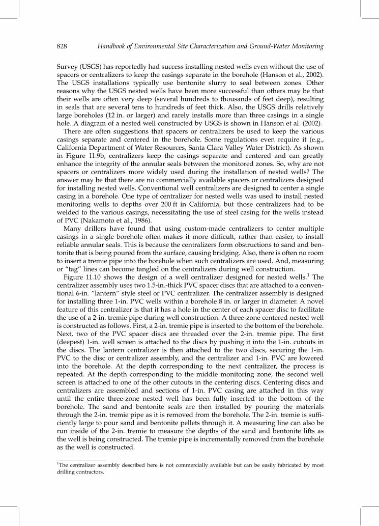
Figure 11.10 shows the design of a well centralizer designed for nested wells.1 Thecentralizer assembly uses two 1.5-in.-thick PVC spacer discs that are attached to a conven-tional 6-in. “lantern” style steel or PVC centralizer. The centralizer assembly is designedfor installing three 1-in. PVC wells within a borehole 8 in. or larger in diameter. A novelfeature of this centralizer is that it has a hole in the center of each spacer disc to facilitatethe use of a 2-in. tremie pipe during well construction. A three-zone centered nested wellis constructed as follows. First, a 2-in. tremie pipe is inserted to the bottom of the borehole.Next, two of the PVC spacer discs are threaded over the 2-in. tremie pipe. The first(deepest) 1-in. well screen is attached to the discs by pushing it into the 1-in. cutouts inthe discs. The lantern centralizer is then attached to the two discs, securing the 1-in.PVC to the disc or centralizer assembly, and the centralizer and 1-in. PVC are loweredinto the borehole. At the depth corresponding to the next centralizer, the process isrepeated. At the depth corresponding to the middle monitoring zone, the second wellscreen is attached to one of the other cutouts in the centering discs. Centering discs andcentralizers are assembled and sections of 1-in. PVC casing are attached in this wayuntil the entire three-zone nested well has been fully inserted to the bottom of theborehole. The sand and bentonite seals are then installed by pouring the materialsthrough the 2-in. tremie pipe as it is removed from the borehole. The 2-in. tremie is suffi-ciently large to pour sand and bentonite pellets through it. A measuring line can also berun inside of the 2-in. tremie to measure the depths of the sand and bentonite lifts asthe well is being constructed. The tremie pipe is incrementally removed from the boreholeas the well is constructed.
1The centralizer assembly described here is not commercially available but can be easily fabricated by mostdrilling contractors.
828 Handbook of Environmental Site Characterization and Ground-Water Monitoring

Well Clusters (One Well per Borehole)
A cluster of monitoring wells is a grouping of individual wells, each completed to a differ-ent depth (Figure 11.6). The main advantage of well clusters over nested wells is that theseals are easier to install and more reliable because there is only one casing in each bore-hole. It is for this reason that well clusters are widely recommended by governmental andregulatory agencies. As with nested wells, the screened interval of each well in the clustershould be no more than 2 or 3 ft long so that the head measurements and ground-watersamples from each well will be depth discrete and not composited over a larger part ofthe aquifer.
The main disadvantage of clusters of wells is the increased cost of drilling separateboreholes for each well. Costs for well clusters are especially high if each boreholeneeds to be continuously cored. In some cases it is sufficient to continuously core thedeepest boring and then design the entire well cluster based on the data obtained fromthe single core. However, if one expects significant variations in the geology, even overshort horizontal distances (e.g., in fractured bedrock or fluvial deposits), then eachborehole in the cluster should be cored. This can add significant cost to the well clusterinstallation.
In plan view, the individual wells in the cluster should be installed close together, on theorder of 10 ft apart or less, so that the head data obtained from them is a result of variationsin the vertical head and not horizontal gradients. Also, care should be taken to avoidinstalling clusters of monitoring wells with overlapping screens. As shown inFigure 11.11, overlapping screens can allow vertical movement of contaminant plumesif vertical hydraulic gradients are present. Finally, clusters of wells should be installedwith the wells oriented in a line perpendicular to the flow direction or with the deeperwells located progressively in the downgradient direction. This avoids the possibility
2" Sch. 40 PVC tremie pipe
1" Sch. 40 PVC well casing
Spacer Disc (typ.)
Borehole
“Lantern style”centralizer
~1.5"
~6"~2.5"
~1.3"
Dimensions approximate
FIGURE 11.10Design of a centralizer for a three-zone nested well. See text for further discussion.
Multilevel Ground-Water Monitoring 829

that the wells will be sampling ground water that is affected by contact with the annularseal of an upgradient monitoring well.
At sites underlain by unconsolidated sedimentary deposits, the use of clusters ofindividual wells for multilevel monitoring is becoming more and more economical (andtherefore more popular) due to the use of DP installation methods and small-diametermonitoring wells with prepacked well screens. At many sites, several clusters of small-diameter wells can be installed in a single day using powerful DP rigs.
Dedicated Multilevel Ground-Water Monitoring Systems
There are several dedicated multilevel ground-water monitoring systems currently on themarket. Four commercially available systems that have seen relatively widespread use are:the Westbay MPw system; the Solinst WaterlooTM system; the Solinst CMTTM system; andthe Water FLUTeTM system. A comparison of these systems is presented in Table 11.1; eachsystem is also described in detail below. These dedicated multilevel systems offer thefollowing advantages.
. They facilitate the collection of ground-water samples and measurement ofhydraulic heads from many more discrete depths than is practical with nestedwells or well clusters (e.g., 10 or more discrete depths can be monitored withmost dedicated multilevel monitoring systems).
. Only one pipe (or tube) is placed in the borehole. This simplifies the process ofinstalling annular seals between the monitored zones and improves the reliabilityof the seals (e.g., compared with nested wells).
. Total project costs can be significantly lower due to reduced drilling costs, lesssecondary waste, less time spent monitoring and sampling, and fewer wells fordecommissioning.
. The volume of purge water produced during routine sampling is decreased oreliminated, reducing costs related to storage, testing, transport and disposal ofpurged fluids.
101
100
98
99
97
Ground waterFlow
FIGURE 11.11Cluster of monitoring wells with overlapping well screens. If vertical gradients are present, well clusters installedlike this can lead to short-circuiting of the contaminant plume and cross-contamination of the aquifer.
830 Handbook of Environmental Site Characterization and Ground-Water Monitoring

TAB
LE11.1
Co
mp
aris
on
of
Fo
ur
Ded
icat
edM
ult
ilev
elG
rou
nd
-Wat
erM
on
ito
rin
gS
yst
ems
De
scri
pti
on
We
stb
ay
MP�R
Sy
ste
m
So
lin
stW
ate
rlo
oT
M
Sy
ste
m
So
lin
stC
MT
TM
Sy
stem
Wa
ter
FL
UT
eT
M
Sy
stem
Co
mm
en
ts
Mat
eria
lsP
VC
,p
oly
ure
than
e,V
ito
n,
and
stai
nle
ssst
eel
PV
C,
stai
nle
ssst
eel,
Vit
on
,ru
bb
er,
and
Tefl
on
or
po
lyet
hy
len
etu
bin
g
Po
lyet
hy
len
ean
dst
ain
less
stee
lP
oly
ure
than
e-co
ated
ny
lon
,st
ain
less
stee
lo
rb
rass
,an
dp
oly
eth
yle
ne,
PV
DF,
or
Tefl
on
tub
ing
Mat
eria
lsv
ary
dep
end
ing
on
seal
ing
and
pu
mp
ing
op
tio
ns
Max
imu
md
epth
(ft)
4000
750
300
1000
Max
imu
md
epth
for
rou
tin
ein
stal
lati
on
sM
axim
um
nu
mb
ero
fsa
mp
lin
gp
oin
ts20
per
100
fto
fw
ell
157
20þ
Wit
hex
cep
tio
no
fW
estb
aysy
stem
,dep
end
so
nd
iam
eter
of
syst
eman
dsi
zeo
fsa
mp
lin
gtu
bes
All
ow
su
seo
fp
ress
ure
tran
sdu
cers
tom
on
ito
rh
yd
rau
lic
pre
ssu
re
��
��
Wes
tbay
MP
syst
emu
ses
asp
ecia
lize
dto
ol
for
sam
ple
coll
ecti
on
and
pre
ssu
rem
easu
rem
ent
(see
tex
t)D
edic
ated
pre
ssu
rese
nso
rsca
nal
sob
ein
stal
led
Max
imu
msa
mp
lin
gp
oin
tsw
hen
ded
icat
edp
ress
ure
tran
sdu
cers
are
use
din
each
mo
nit
ore
dzo
ne
See
com
men
ts8
320þ
Wit
hW
estb
ayM
Psy
stem
,d
edic
ated
pre
ssu
rese
nso
rsm
ust
be
rem
ov
edp
rio
rto
coll
ecti
ng
gro
un
d-w
ater
sam
ple
sfr
om
the
sam
ezo
nes
Sam
pli
ng
met
ho
ds
See
com
men
tsP
eris
talt
icp
um
p,
iner
tial
-lif
tp
um
p,
do
ub
le-v
alv
ep
um
p,
bla
dd
erp
um
p
Per
ista
ltic
pu
mp
,in
erti
al-l
ift
pu
mp
,d
ou
ble
-val
ve
pu
mp
Per
ista
ltic
pu
mp
,in
erti
al-l
ift
pu
mp
,d
ou
ble
-val
ve
pu
mp
,b
lad
der
pu
mp
Wes
tbay
syst
emu
ses
spec
iali
zed
too
lfo
rsa
mp
leco
llec
tio
nan
dp
ress
ure
mea
sure
men
t(s
eete
xt)
Op
tim
alb
ore
ho
led
iam
eter
(in
.)3
–6
3–
63
–6
3–
10
(Tab
leco
nti
nued
)
Multilevel Ground-Water Monitoring 831

TAB
LE11.1
Con
tin
ued
De
scri
pti
on
We
stb
ay
MP�R
Sy
ste
m
So
lin
stW
ate
rlo
oT
M
Sy
ste
m
So
lin
stC
MT
TM
Sy
stem
Wa
ter
FL
UT
eT
M
Sy
stem
Co
mm
en
ts
Bu
ilt-
infe
atu
res
for
wel
ld
evel
op
men
tan
dh
yd
rau
lic
test
ing
�—
——
Can
be
inst
alle
dim
med
iate
lyaf
ter
wel
ld
esig
ned
;th
atis
,n
od
elay
du
eto
ship
pin
gcu
sto
miz
edw
ellc
om
po
nen
tsto
site
fro
mfa
cto
ry
��
�—
Rem
ov
able
syst
em�
�—
�S
oli
nst
Wat
erlo
osy
stem
rem
ov
able
wh
end
eflat
able
pac
ker
su
sed
.D
eflat
able
pac
ker
su
nd
erd
evel
op
men
tfo
rS
oli
nst
CM
Tsy
stem
wil
lm
ake
itre
mo
vab
le.
Su
cces
sfu
lre
mo
val
of
any
mu
lti-
lev
elsy
stem
dep
end
so
nb
ore
ho
leco
nd
itio
ns
Can
be
inst
alle
din
op
enh
ole
sin
bed
rock
and
mas
siv
ecl
ayd
epo
sits
��
��
Can
be
inst
alle
din
un
con
soli
dat
edd
epo
sits
��
��
Can
be
inst
alle
din
mu
ltis
cree
ned
wel
ls�
��
�
Sea
lsan
dsa
nd
pac
kca
nb
ein
stal
led
by
bac
kfi
llin
gfr
om
surf
ace
��
�—
FL
UT
esy
stem
seal
sb
ore
ho
le;
oth
eran
nu
lar
seal
sar
eth
eref
ore
no
tn
eed
edIn
flat
able
pac
ker
sav
aila
ble
for
seal
ing
bo
reh
ole
inb
edro
cko
rm
ult
iscr
een
edw
ells
��
——
Infl
atab
lep
ack
ers
un
der
dev
elo
pm
ent
for
So
lin
stC
MT
syst
em.
Wat
erF
LU
Te
syst
emca
nb
eth
ou
gh
to
fas
on
elo
ng
pac
ker
Can
be
inst
alle
dw
ith
DP
(e.g
.,G
eop
rob
e)eq
uip
men
t—
—�
�
832 Handbook of Environmental Site Characterization and Ground-Water Monitoring
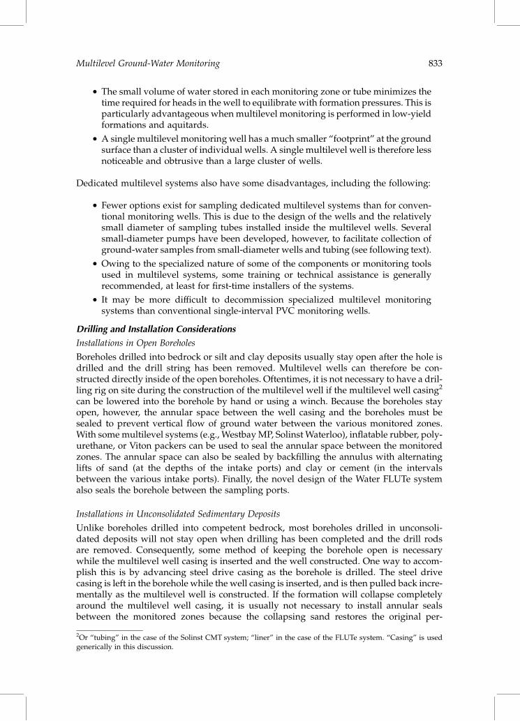
. The small volume of water stored in each monitoring zone or tube minimizes thetime required for heads in the well to equilibrate with formation pressures. This isparticularly advantageous when multilevel monitoring is performed in low-yieldformations and aquitards.
. A single multilevel monitoring well has a much smaller “footprint” at the groundsurface than a cluster of individual wells. A single multilevel well is therefore lessnoticeable and obtrusive than a large cluster of wells.
Dedicated multilevel systems also have some disadvantages, including the following:
. Fewer options exist for sampling dedicated multilevel systems than for conven-tional monitoring wells. This is due to the design of the wells and the relativelysmall diameter of sampling tubes installed inside the multilevel wells. Severalsmall-diameter pumps have been developed, however, to facilitate collection ofground-water samples from small-diameter wells and tubing (see following text).
. Owing to the specialized nature of some of the components or monitoring toolsused in multilevel systems, some training or technical assistance is generallyrecommended, at least for first-time installers of the systems.
. It may be more difficult to decommission specialized multilevel monitoringsystems than conventional single-interval PVC monitoring wells.
Drilling and Installation Considerations
Installations in Open Boreholes
Boreholes drilled into bedrock or silt and clay deposits usually stay open after the hole isdrilled and the drill string has been removed. Multilevel wells can therefore be con-structed directly inside of the open boreholes. Oftentimes, it is not necessary to have a dril-ling rig on site during the construction of the multilevel well if the multilevel well casing2
can be lowered into the borehole by hand or using a winch. Because the boreholes stayopen, however, the annular space between the well casing and the boreholes must besealed to prevent vertical flow of ground water between the various monitored zones.With some multilevel systems (e.g., Westbay MP, Solinst Waterloo), inflatable rubber, poly-urethane, or Viton packers can be used to seal the annular space between the monitoredzones. The annular space can also be sealed by backfilling the annulus with alternatinglifts of sand (at the depths of the intake ports) and clay or cement (in the intervalsbetween the various intake ports). Finally, the novel design of the Water FLUTe systemalso seals the borehole between the sampling ports.
Installations in Unconsolidated Sedimentary Deposits
Unlike boreholes drilled into competent bedrock, most boreholes drilled in unconsoli-dated deposits will not stay open when drilling has been completed and the drill rodsare removed. Consequently, some method of keeping the borehole open is necessarywhile the multilevel well casing is inserted and the well constructed. One way to accom-plish this is by advancing steel drive casing as the borehole is drilled. The steel drivecasing is left in the borehole while the well casing is inserted, and is then pulled back incre-mentally as the multilevel well is constructed. If the formation will collapse completelyaround the multilevel well casing, it is usually not necessary to install annular sealsbetween the monitored zones because the collapsing sand restores the original per-
2Or “tubing” in the case of the Solinst CMT system; “liner” in the case of the FLUTe system. “Casing” is usedgenerically in this discussion.
Multilevel Ground-Water Monitoring 833

meability of the formation. If the formation will not collapse completely around the multi-level well casing, however, gaps can exist in the annular space, allowing vertical flow ofground water between different monitoring zones. In this case, alternating layers ofsand and bentonite or cement must be emplaced by backfilling as the steel drive casingis withdrawn from the borehole. Drilling methods that employ driven casing includeair-rotary casing advance and rotasonic (Barrow, 1994). Rotasonic drilling (also referredto simply as sonic drilling) is ideal for installing multilevel monitoring wells because (1)steel drive casing is advanced as drilling progresses; (2) continuous cores are routinely col-lected (logs of the cores can then be used to design the multilevel wells); and (3) the rate ofpenetration is usually high.
Two of the multilevel monitoring systems, Solinst CMT and Water FLUTe, can beinstalled with DP drilling equipment. Both the multilevel systems can be inserted intosmall-diameter (approximately 3 in. OD) steel casing that has been driven to the targetdepth. Use of a dual-tube DP system facilitates collection of continuous cores while advan-cing an outer drive casing that can then be retracted as the multilevel well is constructed(Einarson, 1995). Because of the relatively small size of most DP sampling rigs, however,the maximum depth of multilevel wells installed with this drilling method is approxi-mately 50 ft in most sedimentary deposits.
Multilevel monitoring wells can also be installed in boreholes drilled with hollow-stemaugers and mud rotary drilling methods, but these drilling methods have some significantdrawbacks. Hollow-stem augers keep the borehole open while allowing the multilevelwell casing to be inserted through the augers to the bottom of the borehole. Sand packsand annular seals are then emplaced as the augers are incrementally removed from theborehole. The action of the augers during drilling, however, often creates a skin ofsmeared fine-grained soil which can seal some thin, permeable strata or fractures inclay (D’Astous et al., 1989) and generally reduce the permeability of the formationalong the entire length of the borehole. Also, if the augers penetrate soil containing highconcentrations of contaminants (either residual NAPL or sorbed mass), the contaminantscan be smeared against the borehole wall from the depth that they were penetrated up tothe ground surface. This can impart a long-lived positive bias to ground-water samplescollected from a multilevel well subsequently installed in the borehole.
Multilevel monitoring wells can be installed in boreholes drilled with mud rotary dril-ling equipment, but this drilling method too has undesirable effects when it comes toinstalling multilevel wells. With mud rotary drilling, the borehole is kept open by(1) the hydrostatic pressure of the drilling fluid (drilling mud) and (2) the creation of atough, pliable filter cake or clay “skin” that develops from exfiltration of the drillingfluid through the borehole wall. Circulation of the drilling fluid, however, can cross-contaminate the borehole if contaminants in the drilling fluid penetrate the formation(by advection or diffusion) or sorb onto the borehole wall. This can cause a lingeringchemical bias similar to the one described above for wells installed with hollow-stemauger drilling equipment. Also, it is often more difficult to place sand packs andannular seals in mud-filled boreholes than boreholes containing air or clear water. Thisis because the high density and viscosity of the drilling fluid makes it difficult to poursand and bentonite pellets through the drilling fluid (many contractors will thereforethin the drilling mud with water prior to building a well). In most cases, though, thesand and bentonite or cement must be pumped through a tremie pipe. Finally, the drillingfluid and filter cake may be difficult to remove after the multilevel well has been con-structed. With the exception of the Westbay MP system, none of the multilevel systemsdescribed in this section facilitate robust well development to remove the drilling mudand filter cake. Therefore, the Westbay MP system would be a good choice for a multilevelwell installed in a mud-rotary drilled borehole. Other multilevel systems have been
834 Handbook of Environmental Site Characterization and Ground-Water Monitoring

installed successfully in boreholes drilled using biodegradable drilling fluids (e.g., guar-based slurries), however. The use of a biodegradable drilling fluid reduces the need forvigorous well development to remove the drilling mud and filter cake.
Another way to install the dedicated multilevel systems described in this section isinside of multiscreened wells instead of directly in boreholes (Figure 11.12). With thistype of installation, the multilevel monitoring system is installed inside a steel or PVCwell that has been constructed with short screens at multiple depths. The depths of thewell screens correspond to the depths of the ports in the multilevel monitoring system.This adds another step to the well installation process (i.e., first installing a multiscreenedwell), but has several advantages. First, installing conventional steel or PVC wells isstraightforward and routine for most drilling contractors. Hence, it is not necessary thatthe drilling contractor have expertise in installing multilevel monitoring systems. Oncethe multiscreened wells have been installed and developed, the drilling contractor’s jobis done, and the multilevel systems can be installed by field technicians, often at alower cost. Secondly, the various monitoring zones can be developed using standardwell development equipment and procedures before the multilevel monitoring systems
Bentonite orcement seal(typ.)
Sand pack(typ.)
PVC wellscreens (typ.)
Blank PVCcasing (typ.)
Intake port(typ.)
Packer seal(typ.)
Multi-levelwell
Borehole
FIGURE 11.12A dedicated multilevel monitoring system installed inside a steel or PVC well constructed with multiple wellscreens.
Multilevel Ground-Water Monitoring 835

are installed in the wells. Finally, installing multilevel systems inside multiscreened wellsmay simplify the task of decommissioning the wells once they are no longer needed. Mostof the multilevel systems can be constructed so that they can be easily removed from thewells. Then, the multi-screened wells can be pressure-grouted or drilled out using stan-dard well decommissioning procedures (see Chapter 12).
Minimizing Cross-Contamination
A properly constructed multilevel monitoring well should clearly prevent vertical “shortcircuiting” of ground water between different monitored zones. As discussed earlier,however, cross-contamination can occur in the borehole before the well is constructed.Cross-contamination can occur if NAPL is penetrated and becomes incorporated in thedrilling fluid or flows into and along the borehole wall. This severe form of cross-contamination (and ways to avoid it during drilling) is described elsewhere (seePankow and Cherry, 1996) and is therefore not discussed further in this chapter.
The cross-contamination discussed in this section is related to the redistribution ofdissolved solutes within the borehole both during and after drilling — but before thewell is constructed. Cross-contamination of fluids in the borehole during drilling hasalready been discussed and recommendations made to avoid it. In short, when drillingin unconsolidated deposits (both sand and gravel aquifers and low permeability claydeposits), advancing steel casing while drilling is the best way to minimize the potentialfor cross-contamination of dissolved solutes in the borehole. The drive casing stays in theground until the multilevel well is ready to be constructed, and is retracted incrementallyas the multilevel well is being built. In boreholes drilled in rock, however, it is usually notpossible to advance steel casing, and some degree of cross-contamination in the boreholeshould be expected due to the circulation of fluids (either drilling mud, water, orcompressed air). Note that the potential bias caused by circulation of fluids during drillingis not restricted to boreholes drilled for multilevel wells but can occur with all types ofmonitoring wells.
Further, if a multilevel well is not installed in an open borehole immediately after dril-ling ceases, vertical flow of potentially contaminated ground water can occur in the bore-hole from zones of high head to low head during the time that the borehole has beendrilled and the multilevel well installed. To minimize potential chemical biases causedby this intra-borehole flow, the multilevel well should be installed in the borehole asquickly as possible. If this is not possible, the borehole can be temporarily sealed toprevent ambient vertical flow. This has been done at several sites using blank FLUTeliners. (Several technologies to temporarily seal boreholes drilled in fractured rock [includ-ing FLUTe] are currently being evaluated by researchers at the University of Waterloo[Cherry, 2004].) Partial mitigation of this bias may be accomplished by pumping fromthe various monitoring zones immediately after the well has been constructed, but low-level contamination may linger for months or years if the contaminants have sorbedonto or diffused into the aquifer matrix (Sterling et al., 2005). The likelihood (and potentiallongevity) of a positive ground-water sampling bias occurring due to circulation ofdrilling fluids and intra-borehole ground-water flow after drilling depends on manyfactors, including the nature and concentration of the contaminant, the nature of thegeologic material, the time of exposure, and extent of penetration into the formation,and must be evaluated on a case-by-case basis.
Development of Multilevel Wells
The purpose of multilevel monitoring wells is to provide depth-discrete samples ofground water and accurate depth-discrete measurements of hydraulic head. They are
836 Handbook of Environmental Site Characterization and Ground-Water Monitoring

not designed to provide large volumes of water as are water supply or remediation wells.Consequently, the requirements for developing multilevel monitoring wells are differentthan for other types of wells. In general, as long as there is good hydraulic connectionbetween the monitoring ports and the formation and the samples collected from thewells are sediment-free and exhibit turbidity within reasonable levels, the above require-ments are met. With each of the dedicated multilevel systems described in this chapter,this level of well development can usually be achieved simply by over-pumping thevarious ports with the pumps used for sampling. In the case of wells installed in boreholesdrilled with mud rotary methods, however, more rigorous development is necessary. Thiscan be accomplished best with any of the four multilevel systems provided that they areinstalled in multiscreened wells that have already been developed using traditional devel-opment methods. Over-pumping is also often done to remove water added to the boreholeduring drilling and well construction. This is due to widely held concern that if this wateris not removed, it could cause a negative bias in the samples subsequently collected fromthe well. If the volume of water that needs to be removed is small, the water can beremoved by pumping the zones using the same pumps used for sampling (the WestbayMP system allows for use of higher capacity pumps for well purging). Air lift techniqueshave also been used successfully to pump water at relatively high rates from small-diameter sampling tubes (see Einarson and Cherry, 2002). Finally, in most flowing aqui-fers, it is usually sufficient to simply allow some time to pass before collecting the firstsamples in order to allow the added water to drift away from the intake ports of thewell. In most cases the added water will have drifted away from the intake ports of themultilevel wells in several days and samples collected from the well will be groundwater. Some site investigators have added an inert tracer (e.g., potassium bromide) tothe water used during drilling and well construction. They then pump water from thevarious ports (or let sufficient time pass for the added water to drift away from thesampling ports) until the tracer is no longer detected. They can then be confident thatground-water samples collected thereafter consist entirely of ground water and notwater added during drilling or well construction.
Westbay MP System
Schlumberger produces the Westbay MP system, a modular instrumentation system formultilevel ground-water monitoring. The MP system can be divided into two parts:(1) the casing system and (2) portable probes and tools that provide a compatible dataacquisition system.
The Westbay casing system (Figure 11.13) is designed to allow the monitoring of mul-tiple discrete levels in a single borehole. One single string of water-tight Westbay casingis installed in the borehole. Each level or monitoring zone has valved couplings toprovide a selective, controlled connection between the ground water outside the casingand instruments inside the casing. Westbay packers or backfill are used to seal the bore-hole between monitoring zones to prevent the unnatural vertical flow of ground waterand maintain the natural distribution of fluid pressures and chemistry. The Westbaysystem can be installed in either open boreholes or cased wells with multiple screens.
Westbay system packers are individually inflated with water to pressures of 100–200 psiabove ambient. Westbay packers accommodate a range of borehole sizes (Table 11.1) and,according to the manufacturer, withstand significant gradients along the borehole.
Data are obtained using one or more wireline probes with sensors that are loweredinside the casing to each monitoring zone. The probes locate and open the valved portsto measure fluid pressure, collect fluid samples or test hydrogeologic parameters. Multipleprobes can be connected in series to provide continuous multilevel data. Software permits
Multilevel Ground-Water Monitoring 837

notebook computers to interface with the probes and collect data at the surface or from aremote location.
The design of the MP system results in no restriction to the number of zones that can becompleted in one borehole, apart from the physical ability to fit the length of the com-ponents in the well. The user can have materials on site ahead of time as it is not necessaryto know the precise size of the borehole or the desired location of seals and monitoringzones before the equipment is shipped. Users also have access to a wide range of monitor-ing and testing capabilities such as manual or automated monitoring of pressure (waterlevel), discrete sampling without repeated purging, pulse testing of low-permeabilityenvironments, rising- or falling-head (slug) or constant-head hydraulic conductivitytesting, vertical interference testing, and cross-well testing (including injection and with-drawal of tracers) (Figure 11.14). Pressure measurements are made under shut-in con-ditions, making the system responsive to pressure changes. Ground-water samples arecollected at formation pressure without repeated purging.
The Westbay system has been in use since 1978 and has been installed in a variety ofgeologic environments ranging from soft seabed sediments to unconsolidated alluvialdeposits, to highly fractured bedrock. Examples of project applications include environ-mental characterization related to ground-water contamination (e.g., Raven et al., 1992;Gernand et al., 2001; Taraszki et al., 2002) to ground-water resource management(Black et al., 1988), and characterization and monitoring related to nuclear waste reposi-tories (Delouvrier and Delay, 2004). Depths of installation varied from 100 ft (30 m) togreater than 4000 ft (1200 m).
Westbay instrumentation is sold as a complete system and Westbay technicians assistwith initial installations and provide on-site training of local personnel. Field quality-control procedures permit the quality of the well installation and the operation of thetesting and sampling equipment to be verified at any time.
MonitoringZone
Packer:Individual hydraulicinflation
Measurement Port:For pressure measurementsampling, and low-K testing
Pumping Port:For purging andhydraulic testing
Casing:Varying lengths forversatility of well design
FIGURE 11.13The Westbay MPw system.
838 Handbook of Environmental Site Characterization and Ground-Water Monitoring

A detailed technical description of the Westbay multilevel monitoring system ispresented by Black et al. (1986). Further information about the Westbay multilevelsystem can be obtained from Westbay Instruments Inc. (www.westbay.com) and fromits parent company, Schlumberger Water Services (www.slb.com/waterservices).
Solinst Waterloo System
The Solinst Waterloo Multilevel ground-water monitoring system is a modular multilevelmonitoring system manufactured by Solinst Canada, Ltd. to collect ground-water datafrom multiple depths within a single drilled borehole. Originally developed by research-ers at the University of Waterloo (Cherry and Johnson, 1982), it consists of a series of moni-toring ports positioned at specific intervals along 2-in. Schedule 80 PVC casing(Figure 11.15). The ports are typically isolated in the borehole either by in-line packers(permanent or removable), or by alternating layers of sand and bentonite backfilledfrom the surface. The Solinst Waterloo Multilevel system can also be installed insidemulti-screened wells.
The ports and packers are connected to the 2-in. Schedule 80 PVC casing with a specialwater-tight joint. Monitoring ports are constructed of stainless steel or PVC and have thesame water-tight joint to connect with the other system components. Water is added to theinside of the 2-in. PVC casing to overcome buoyancy during installation and to inflatepermanent or deflatable packers (if used). A case study in which a removable Waterloomultilevel monitoring system equipped with deflatable packers was used is presentedby Sterling et al. (2005).
SingleProbe
SamplerProbewithContainer(s)
PressureProbe
SamplerProbe
MultiplePressureProbes
OpenPumpingPort
a. Manual pressuremeasurement
b. Open pumpingport for purgingor testing
c. Discrete sampling &
low-K testing
d. Automatedmonitoring
e. Verticalinterferencetesting
FIGURE 11.14Options for pumping, testing, and monitoring with the Westbay MP system. See text for discussion.
Multilevel Ground-Water Monitoring 839

Each monitoring port has either a single or dual stem. Each stem is connected to either:(1) an open tube that runs inside the 2-in. PVC casing to the ground surface; (2) a doublevalve pump; (3) a bladder pump; or (4) a pressure transducer. Pressure transducers can beconnected to a data logger for continuous recording of water levels. If open tubes are con-nected to the port stems, samples can be obtained from inside the tubes using a peristalticpump, an inertial-lift (i.e., check-valve) pump, or a double-valve gas-drive (positive dis-placement) pump. Water levels can also be measured in the open tubes using small-diameter water-level meters. Because each port is plumbed to some type of monitoringdevice, contact between ground water entering the ports and water added to the insideof the 2-in. PVC casing is prevented. If a single stem is used, only one monitoring
O-Ring (typ.)
Shear tie slot (typ.)
Rubber outer sheath
Sample tubing (runsinside of packer)
Perforated packer body
Stainless steel clamp
Fracture(typ.)
Shear tie (typ.)
Sample entry port
Filter screen
Sch. 80 PVC
Port stem
Not to scale (Inflatable packer model shown)
FIGURE 11.15The Solinst Waterloo Multilevel ground-water monitoring system. (Adapted from Cherry and Johnson [1982],With permission.)
840 Handbook of Environmental Site Characterization and Ground-Water Monitoring

device can be used per monitored zone. If dual stems are used, two devices (e.g., a bladderpump and pressure transducer) can be used per zone.
Depending on the monitoring options chosen, the number of zones that can be moni-tored typically ranges from three to eight, although systems with as many as 15 samplingports have been installed. Systems installed in fractured rock formations are typicallyinstalled in 3- or 4-in.-diameter core holes. A wellhead that facilitates simultaneouspurging and sampling of all monitored zones is available. More information about theSolinst Waterloo System is available from Solinst Canada, Ltd. (www.solinst.com).
Solinst CMT System
The Solinst continuous multichannel tubing (CMT) system is a multilevel ground-watermonitoring system that uses custom-extruded flexible 1.6-in. OD multichannel HDPEtubing to monitor as many as seven discrete zones within a single borehole in eitherunconsolidated sedimentary deposits or bedrock (Figure 11.16). Prior to inserting thetubing in the borehole, ports are created that allow ground water to enter six outerpie-shaped channels (nominal diameter ¼ 0.5 in.) and a central hexagonal centerchannel (nominal diameter ¼ 0.4 in.) at different depths, facilitating the measurementof depth-discrete piezometric heads and the collection of depth-discrete ground-watersamples.
The multichannel tubing can be extruded in lengths up to 300 ft and is shipped in4-ft-diameter coils. The desired length of tubing, equal to the total depth of the multilevelwell, is cut from a coil, and the well is built at the job site based on the hydrogeologic dataobtained from the exploratory boring or other methods (e.g., CPT or geophysical data).The tubing is stiff enough to be easily handled, yet light and flexible enough to allowsite workers to insert the multilevel well hand-over-hand into the borehole.
Construction of the intake ports and screens is done before the CMT tubing is insertedinto the borehole. A small continuous mark along the outside of one of the channels facili-tates identification of specific channels. Depth-discrete intake ports are created by cuttingports through the exterior wall of the tubing into each of the channels at the desireddepths. Channel 1 ports correspond to the shallowest monitoring interval; channel 2ports are created further down the tubing (i.e., to monitor a deeper zone), and so forth.The central channel, channel 7, is open to the bottom of the multilevel well. In this way,the ports of the various channels are staggered both vertically and around the perimeterof the multichannel tubing (Figure 11.16). For most of the installations performed asof 2004, an intake interval of approximately 6 in. has been created. The depth interval ofthe intake ports can be increased by cutting more ports in the tubing.
Stagnant water in the tubing below the intake ports is hydraulically isolated by pluggingthe channels a few inches below each intake port. This has been done by inserting andexpanding a mechanical plug into each channel. Expanding mechanical plugs are alsoinserted into each of the outer six channels at the very bottom of the tubing. This effectivelyseals the various channels from just below the intake ports to the bottom of the tubing.Small vent holes are drilled directly beneath the upper polyethylene plugs (i.e., theplugs located just below the intake ports) to allow air to vent out of the sealed channelsduring installation. The seventh (internal) channel is open to the bottom of the tubing.
Well screens are constructed by wrapping synthetic or stainless steel fabric meshcompletely around the tubing in the interval containing the ports. The mesh is securedto the tubing using stainless steel clamps. The size of the mesh openings can be selectedbased on the grain-size distribution of the particular water-bearing zone being monitored.A guide-point cap containing stainless steel mesh is attached to the bottom of the tubing toenable the central channel to be used as the deepest monitoring zone.
Multilevel Ground-Water Monitoring 841
Sand packs and annular seals between the various monitored zones can be installed bybackfilling the borehole with alternating layers of sand and bentonite. Inflatable rubberpackers for permanent or temporary installations in bedrock aquifers and multiscreenwells are also under development (see Johnson et al., 2002).
Hydraulic heads are measured with conventional waterlevel meters or electronicpressure transducers to generate vertical profiles of hydraulic head. Ground-water
7-channel HDPE tubing
CMT tubing
Zone 2 intake
Zone 3 intake
Zone 6 intake
Zone 1 intake
Zone 5 intake
Zone 4 intake
PVC wellcentralizer (typ.)
5 6 1
234
7
Expansion plugs inall channels except
central one (Zone 7)
Port in guide tipcovered by
stainlesssteel mesh
Guide tip andport assembly
Zone 7 intake
Stainless steelmesh (covers port)
Port
Expansion plug
Air vent hole
Not to scale
FIGURE 11.16The Solinst CMT system.
842 Handbook of Environmental Site Characterization and Ground-Water Monitoring

samples are collected using peristaltic pumps, small-diameter bailers, inertial lift pumps,or small-diameter double-valve pumps.
CMT multilevel wells have been installed to depths up to 300 ft below ground surface,although most systems have been installed to depths under 200 ft. These wells have beeninstalled in boreholes created in unconsolidated deposits and bedrock using a wide rangeof drilling equipment including rotasonic, air rotary, diamond-bit coring, and hollow-stemauger.
A small (1.1 in.) diameter three-channel CMT system has also been developed for instal-lation with DP sampling equipment. Sand pack and bentonite cartridges have also beendeveloped for the three-channel CMT system and are undergoing field trials (unpublishedresults).
The CMT multilevel monitoring system is described in detail in Einarson and Cherry(2002). A case study in California where CMT wells were installed to depths of 200 ftusing sonic drilling equipment is presented by Lewis (2001). The use of CMT wells toassess the fate and transport of MTBE in a chalk aquifer in the U.K. is described byWealthall et al. (2001). More information about the CMT multilevel monitoring systemis available from Solinst Canada, Ltd. (www.solinst.com).
Water FLUTe System
The Water FLUTe (Flexible Liner Underground Technology) is a multilevel ground-watermonitoring system that uses a flexible impermeable liner of polyurethane-coated nylonfabric to isolate more than 20 discrete intervals in a single borehole. The system comesin various sizes and can monitor boreholes from 2 to 20 in. in diameter (most installationsare in 4- to 10-in. diameter boreholes). The system is custom-made at the factory to thecustomer’s specifications. Sampling ports are created in the liner at the specified depthsand small-diameter tubing (0.17 and 0.5 in. OD) is connected to the sampling ports.Pressure transducers and cables (if used) are also installed at the appropriate positionsin the liner. The system is pressure tested to 300 psi at the factory. The system isshipped to the job site on a reel and is lowered to the bottom of the borehole by spoolingthe liner, sampling tubes, transducer cables, etc. off of the reel (Figure 11.17a). The systemis shipped “inside out” which facilitates everting the liner and tubes into the borehole.Once the liner is everted, the sampling tubes and cables are inside the liner. The forcerequired to evert the liner comes from hydrostatic pressure that is created by filling theliner with water at the ground surface. Ground water in the borehole is either displacedby the liner or can be pumped out during the installation. The borehole is sealed overits entire length by the pressurized liner. The system is removable by reversing the instal-lation procedure, and may be installed in open boreholes or multiscreened wells.
Samples are collected by applying gas pressure to the sampling tubes, which forces theground-water sample to the surface (Figure 11.17b). Two check valves are installed in eachof the sampling tubes. One of the check valves prevents the water sample from beingforced back out of the sampling port when the pressure is applied. The second checkvalve prevents the ground-water sample from falling back down the sampling linebetween pressure applications. The system is pumped in three strokes with two purge-pressure applications and one lower-pressure application for sampling. The two purgestrokes completely remove all stagnant water from the system. All ports can bepurged and sampled simultaneously because the dedicated pump system for each portis essentially the same length regardless of the port depth. Hence, each port producesthe same purge and sample volume.
Depth-to-water measurements can be made inside the sampling tubing using small-diameter water-level meters. Optional dedicated pressure transducers facilitate continu-
Multilevel Ground-Water Monitoring 843

ous, long-term pressure monitoring. The pressure transducers do not interfere withsampling or manual water-level measurement, or limit the number of ports on the system.
The eversion installation procedure allows installation into nearly horizontal angledholes. A smaller diameter Water FLUTe system has been successfully installed in DPholes with five ports to 60 ft. The seal of the hole is provided by the pressurized liner;no sealing backfill or hole collapse is typically required.
According to the manufacturer, other FLUTe flexible liner systems are used for thefollowing hydrologic applications:
. Sealing of boreholes with blank liners
. Hydraulic conductivity profiling of a borehole while installing a sealing liner
. Multilevel sampling in the vadose zone
. Color reactive mapping of LNAPL and DNAPL in boreholes and cores
. Liner augmentation of horizontal drilling
. Towing of logging tools and cameras into boreholes
More information about the FLUTe system can be obtained from Flexible Liner Under-ground Technologies, Ltd. (www.flut.com).
Watersample
Pressurizedgas
Excess headin liner
Samplingport (typ.)
Check valve #1Check valve #2
Tube from portto check-valve
FLUTe system(inside out)
Water levelin liner
Water levelin formation
Water hose
Wellhead
FLUTe liner in borehole
(a) (b)
Note: Only one sampling pump shown for clarity
BoreholeSample tube
0.5" pressurizationtube
FLUTe linerin borehole
Note: sampling tubes omitted for clarityNot to scale
FIGURE 11.17The Water FLUTe system. (a) Installation of a Water FLUTe system; (b) Collecting ground water samples with aWater FLUTe multilevel system.
844 Handbook of Environmental Site Characterization and Ground-Water Monitoring
References
Akindunni, F.F., R.W. Gillham, B. Conant, Jr., and T. Franz, Modeling of contaminant movementnear pumping wells: saturated-unsaturated flow with particle tracking, Ground Water, 33(2),264–274, 1995.
Aller, L., T.W. Bennett, G. Hackett, R.J. Petty, J.H. Lehr, H. Sedoris, D.M. Nielsen, and J.E. Denne,Handbook of Suggested Practices for the Design and Installation of Ground-Water MonitoringWells, EPA/600/4-89/034, U.S. Environmental Protection Agency, Las Vegas, NV, CooperativeAgreement CR-812350-01, 1989, 245 pp.
Barrow, J.C., The resonant sonic drilling method: An innovative technology for environmentalrestoration programs, Ground Water Monitoring and Remediation, 14(2), 153–160, 1994.
Black, W.H., H.R. Smith, and F.D. Patton, Multiple-Level Ground-Water Monitoring With the MPSystem, Proceedings of the Conference on Surface and Borehole Geophysical Methods andGround Water Instrumentation, National Water Well Association, Dublin, OH, 1986, pp. 41–60.
Black, W.H., J.A. Goodrich, and F.D. Patton, Ground-Water Monitoring for Resource Management,paper presented at ASCE International Symposium on Artificial Recharge of Ground Water,Anaheim, CA, August 21–28, 1988, pp. 1–7.
Borden, R.C., R.A. Daniel, L.E.I. LeBrun, and C.W. Davis, Intrinsic biodegradation of MTBE andBTEX in a gasoline-contaminated aquifer, Water Resources Research, 33(5), 1105–1115, 1997.
California Department of Water Resources, California Water Well Standards, Bulletin 74-90,California Department of Water Resources, Sacramento, CA, 1990.
Cherry, J.A., personal communication, 2004.Cherry, J.A. and P.E. Johnson, A multi-level device for monitoring in fractured rock, Ground-Water
Monitoring Review, 2(3), 41–44, 1982.Cherry, J.A., J.F. Barker, P.M. Buszka, J.P. Hewetson, and C.I. Mayfield, Contaminant Occurrence in
an Unconfined Sand Aquifer at a Municipal Landfill, Proceedings of the Fourth AnnualMadison Conference on Applied Research and Practice on Municipal and Industrial Waste,University of Wisconsin, Madison, Wisconsin, 1981, pp. 1–19.
Cherry, J.A., R.W. Gillham, E.G. Anderson, and P.E. Johnson, Migration of contaminants in groundwater at a landfill: a case study 2. Ground-water monitoring devices, Journal of Hydrology, 63,31–49, 1983.
Chiang, C., G. Raven, and C. Dawson, The relationship between monitoring well and aquifer soluteconcentrations, Ground Water, 33(5), 718–726, 1995.
Church, P.E. and G.E. Granato, Bias in ground-water data caused by well-bore flow in long-screenwells, Ground Water, 34(2), 262–273, 1996.
Conant, B., Jr., F.F. Akindunni, and R.W. Gillham, Effect of well-screen placement on recovery ofstratified contaminants, Ground Water, 33(3), 445–457, 1995.
D’Astous, A.Y., W.W. Ruland, R.G. Bruce, J.A. Cherry, and R.W. Gillham, Fracture effects in theshallow ground water zone in weathered Sarnia-Area Clay, Canadian Geotechnical Journal, 26,43–56, 1989.
Delouvrier, J. and J. Delay, Multi-Level Ground-Water Pressure Monitoring at the Meuse/Haute-Marne Underground Research Laboratory, France, Proceedings of EurEnGeo 2004,Liege, Belgium, May, 2004, pp. 377–384.
Devlin, J.F., M.L. McMaster, D.J. Katic, and J.F. Barker, 2001, Evaluating Natural Attenuation in aControlled Field Experiment by Mass Balances, Flux Fences and Snapshots: A Comparison ofResults, Paper presented at Ground Water Quality 2001, Sheffield, U.K., July 18–21, 2001,pp. 282–285.
Drost, W., D. Klotz, A. Koch, H. Moser, F. Neumaier, and W. Rauert, 1968, Point dilution methodsof investigating ground water flow by means of radioisotopes, Water Resources Research, 4(1),125–146, 1968.
Einarson, M.D., EnviroCore: A new dual-tube direct push system for collecting continuous soil cores,Proceedings of the Ninth National Outdoor Action Conference, National Ground Water Association,Dublin, OH, 1995, pp. 419–433.
Multilevel Ground-Water Monitoring 845
Einarson, M.D. and J.A. Cherry, A new multi-level ground-water monitoring system utilizing multi-channel tubing, Ground-Water Monitoring and Remediation, 22(4), 52–65, 2002.
Einarson, M.D. and D.M. Mackay, Predicting impacts of ground-water contamination, EnvironmentalScience & Technology, 35(3), 66A–73A, 2001.
Elci, A., F. Molz, and W.R. Waldrop, Implications of observed and simulated ambient flow inmonitoring wells, Ground Water, 39(6), 853–862, 2001.
Elci, A., G.P. Flach, and F. Molz, Detrimental effects of natural vertical head gradients on chemicaland water-level measurements in observation wells: identification and control, Journal ofContaminant Hydrology, 28, 70–81, 2003.
Feenstra, S., J.A. Cherry, and B.L. Parker, Conceptual models for the behavior of nonaqueous phaseliquids (DNAPLs) in the subsurface, in Dense Chlorinated Solvents and Other DNAPLs in GroundWater, James F. Pankow and John A. Cherry, Eds., Waterloo Press, Waterloo, Ontario, Canada,pp. 53–88.
Foote, G.R., N.T. Bice, L.D. Rowles, and J.D. Gallinatti, TCE and flow monitoring methods usingan existing water supply well, Journal of Environmental Engineering, June, 564–571, 1998.
Freeze, R.A. and J.A. Cherry, Groundwater, Prentice-Hall, Englewood Cliffs, NJ, 1979, 604 pp.Gernand, J., B. Rundell, and C. Yen, Practical Bedrock Aquifer Characterization Using Borehole
Geophysics and Multilevel Wells, Practice Periodical of Hazardous, Toxic, and RadioactiveWaste Management, 2001, pp. 111–118.
Gibs, J., G.A. Brown, K.S. Turner, C.L. MacLeod, J.C. Jelinski, and S.A. Koehnlein, Effects of small-scalevertical variations in well-screen inflow rates and concentrations of organic compounds on thecollection of representative ground-water quality samples, Ground Water, 31(2), 201–208, 1993.
Gossell, M.A., T. Nishikawa, R.T. Hanson, J.A. Izbicki, M.A. Tabidian, and K. Bertine, Application offlowmeter and depth-dependent water quality data for improved production well construction,Ground Water, 37(5), 729–735, 1999.
Guilbeault, M.A., B.L. Parker, and J.A. Cherry, Mass flux distributions from DNAPL Zones in SandyAquifers, Ground Water, 43(1), 70–86, 2005.
Haas, J.E. and C. Sosik, Smart Pump-and-Treat Strategy for MTBE Impacting a Public Water SupplyWell Field, Proceedings of the Fourteenth Annual Conference on Contaminated Soils, AEHS,Amherst, MA, 1998, pp. 1–31.
Hanson, R.T., M.W. Newhouse, C.M. Wentworth, C.F. Williams, T.E. Noce, and M.J. Bennett,Santa Clara Valley Water District Multi-Aquifer Monitoring Well Site, Coyote CreekOutdoor Classroom, San Jose, California, U.S. Geological Survey, Open-File Report 02-369,2002, 4 pp.
Hutchins, S.R. and S.D. Acree, Ground-water sampling bias observed in shallow conventional wells,Ground-Water Monitoring and Remediation, 20(1), 86–93, 2000.
Jansen, J., Geophysical well logging and discrete water sampling methods to identify sources of elev-ated barium in a water well in Northern Illinois, Proceedings of the Symposium on the Appli-cation of Geophysics to Environmental and Engineering Problems, Society for Environmentaland Engineering Geophysics, Denver, CO, 1998, pp. 315–322.
Johnson, T.L., A comparison of well nests vs. single-well completions; Ground-Water MonitoringReview, 3(1), 76–78, 1983.
Johnson, C.D., F.P. Haeni, and J.W. Lane, Importance of discrete-zone monitoring systems infractured-bedrock wells — a case study from the University of Connecticut Landfill, Storrs,Connecticut, Proceedings of the Symposium on the Application of Geophysics to Engineeringand Environmental Problems, Society for Environmental and Engineering Geophysics, Denver,CO, 2002, pp. 1–4.
Kao, C.M. and Y.S. Wang, Field investigation of natural attenuation and intrinsic biodegra-dation rates at an underground storage tank site, Environmental Geology, 40(4–5), 622–631,2001.
Lewis, M., Installing continuous multi-chamber tubing using sonic drilling, Water Well Journal, July,16–17, 2001, pp. 16–17.
MacFarlane, D.S., J.A. Cherry, R.W. Gillham, and E.A. Sudicky, Migration of contaminants in groundwater at a landfill: a case study 1. ground water flow and plume delineation, Journal of Hydrology,63, 1–29, 1983.
846 Handbook of Environmental Site Characterization and Ground-Water Monitoring

Mackay, D.M., J.A. Cherry, D.L. Freyberg, and P.V. Roberts, A natural gradient experiment on solutetransport in a sand aquifer 1. Approach and overview of plume movement, Water ResourcesResearch, 22(13), 2017–2029, 1986.
Martin-Hayden, J.M., Controlled laboratory investigations of wellbore concentration response topumping, Ground Water, 38(1), 121–128, 2000a.
Martin-Hayden, J.M., Sample concentration response to laminar wellbore flow: implications toground-water data variability, Ground Water, 38(1), 12–19, 2000b.
Martin-Hayden, J.M. and G.A. Robbins, Plume distortion and apparent attenuation due to concen-tration averaging in monitoring wells, Ground Water, 35(2), 339–346, 1997.
Martin-Hayden, J.M., G.A. Robbins, and R.D. Bristol, Mass-balance evaluation of monitoring wellpurging, Part II. Field tests at a gasoline contamination site, Journal of Contaminant Hydrology,8, 225–241, 1991.
McIlvride, W.A. and B.M. Rector, Comparison of short and long-screened wells in alluvialsediments, Proceedings of the Second Outdoor Action Conference, National Ground-WaterAssociation, Dublin, OH, 1988, pp. 375–390.
Nakamoto, D.B., F.R. McLaren, and P.J. Philips, Multiple completion monitor wells, Ground-WaterMonitoring Review, 6(2), 50–55, 1986.
National Research Council, Alternatives for Ground Water Cleanup, National Research Council,Washington, DC, National Academy Press, 1994, 314 pp.
Newell, C.J., J.A. Conner, and D.L. Rowen, Ground Water Remediation Strategies Tool, PublicationNumber 4730, American Petroleum Institute, Washington, DC, 2003, 80 pp.
Pankow, J.F. and J.A. Cherry, Dense Chlorinated Solvents and other DNAPLs in Groundwater, WaterlooPress, Waterloo, Ontario, Canada, 1996, 522 pp.
Parker, L.V. and C.H. Clark, Study of Five Discrete Interval-Type Ground Water Sampling Devices,ERDC/CRREL Publication #TR-02–12, U.S. Army Corps of Engineers, Hanover, NH, 2002, 49 pp.
Pitkin, S.E., J.A. Cherry, R.A. Ingleton, and M. Broholm, Field demonstrations using the Waterlooground-water profiler, Ground-Water Monitoring and Remediation, 19(2), 122–131, 1999.
Puls, R.W. and C.J. Paul, Multi-layer sampling in conventional monitoring wells for improvedestimation of vertical contaminant distribution and mass, Journal of Contaminant Hydrology,25(1), 85–111, 1997.
Raven, K.G., K.S. Novakowski, R.M. Yager, and R.J. Heystee, Supernormal fluid pressures insedimentary rocks of southern Ontario–Western New York State, Canadian GeotechnicalJournal, 29, 80–93, 1992.
Reilly, T.E. and J. Gibs, Effects of physical and chemical heterogeneity on water quality samplesobtained from wells, Ground Water, 31(5), 805–813, 1993.
Reilly, T.E. and D.R. LeBlanc, Experimental evaluation of factors affecting temporal variability ofwater samples obtained from long-screened wells, Ground Water, 36(4), 566–576, 1998.
Reilly, T.E., O.L. Franke, and G.D. Bennett, Bias in ground-water samples caused by well-bore flow,Journal of Hydrologic Engineering, 115, 270–276, 1989.
Reinhard, M., N.L. Goodman, and J.F. Barker, Occurrence and distribution of organic chemicals intwo landfill leachate plumes, Environmental Science & Technology, 18, 953–961, 1984.
Rivett, M.O., Soil-gas signatures from volatile chlorinated solvents: borden field experiments, GroundWater, 33(1), 84–98, 1995.
Robbins, G.A., Influence of purged and partially penetrating monitoring wells on contaminantdetection, mapping and modeling, Ground Water, 27(2), 155–162, 1989.
Robbins, G.A. and J.M. Martin-Hayden, Mass-balance evaluation of monitoring well purging,Part I. Theoretical models and implications for representative sampling, Journal of ContaminantHydrology, 8, 203–224, 1991.
Robertson, W.D., J.A. Cherry, and E.A. Sudicky, Ground-water contamination from two small septicsystems on sand aquifers, Ground Water, 29(1), 82–92, 1991.
Ronen, D., M. Magaritz, and I. Levy, An in-situ multilevel sampler for preventive monitoring andstudy of hydrochemical profiles in aquifers, Ground-Water Monitoring Review, 7(4), 69–74, 1987.
Semprini, L., P.K. Kitanidis, D.H. Kampbell, and J.T. Wilson, Anaerobic transformation of chlori-nated aliphatic hydrocarbons in a sand aquifer based on spatial chemical distributions, WaterResources Research, 31(4), 1051–1062, 1995.
Multilevel Ground-Water Monitoring 847

Smith, R.L., R.W. Harvey, J.H. Duff, and D.R. LeBlanc, Importance of Close-Interval VerticalSampling in Delineating Chemical and Microbiological Gradients in Ground-Water Studies,U.S. Geological Survey, Open File Report 87-109, 1987, pp. B33–B35.
State of Washington, Washington State Administrative Code (WAC), 173-160-420(3), State ofWashington, 2004.
Sterling, S.N., B.L. Parker, J.A. Cherry, J.H. Williams, J.W. Lane, and F.P. Haeni, Vertical crosscontamination of TCE in a borehole in fractured sandstone, Ground Water, in press.
Sukop, M.C., Estimation of vertical concentration profiles from existing wells. Ground Water, 38(6),836–841, 2000.
Taraszki, M., C. Merey, and G. Mitchell, Ground-water quality evaluation using Westbay monitoringwell systems, Former Fort Ord, California, Proceedings of the 2002 National Monitoring Confer-ence, National Water Quality Monitoring Council, Washington, DC, 2002.
U.S. Army Corps of Engineers, Monitoring Well Design, Installation and Documentation at Hazar-dous, Toxic, and Radioactive Waste Sites, Engineer Manual 1110–1-4000, U.S. Army Corps ofEngineers, Washington, DC, 1998, 69 pp.
U.S. EPA, RCRA Ground-Water Monitoring: Draft Technical Guidance. Office of Solid Waste, U.S.Environmental Protection Agency, November 1992. Update to Chapter 11 of SW-846 (Revision 0,September 1986) and the Technical Enforcement Guidance Document (TEGD), 1992.
U.S. EPA, Expedited Site Assessment Tools for Underground Storage Tank Sites — A Guide forRegulators, EPA/510-B-97-001, U.S. Environmental Protection Agency, Washington, DC, 1997.
U.S. EPA, Monitored Natural Attenuation for Ground Water, Seminar Notes, EPA/625/K-98/00, U.S.Government Printing Office, Washington, DC, 1998.
van der Kamp, G., L.D. Luba, J.A. Cherry, and H. Maathuis, Field study of a long and very narrowcontaminant plume, Ground Water, 32(6), 1008–1016, 1994.
Varljen, M.D., M.J. Barcelona, J. Obereiner, and D. Kaminski, Numerical simulations to assess themonitoring zone achieved during low-flow purging and sampling, Ground-Water Monitoringand Remediation, in press.
Vroblesky, D.A. and W.T. Hyde, Diffusion samplers as an inexpensive approach to monitoring VOCsin ground water, Ground-Water Monitoring and Remediation, 17(3), 177–184, 1997.
Vroblesky, D.A., L.C. Rhodes, J.F. Robertson, and J.A. Harrigan, Locating VOC contamination in afractured-rock aquifer at the ground-water/surface-water interface using passive vapor collec-tors, Ground Water, 34(2), 223–230, 1996.
Wealthall, G.P., S.F. Thornton, and D.N. Lerner, 2001, Assessing the Transport and Fate of MTBE-Amended Petroleum Hydrocarbons in the UK Chalk Aquifer, paper presented at GroundWater Quality 2001, Third International Conference on Ground-Water Quality, University of Shef-field, U.K., June 18–21, 2001, pp. 369–374.
848 Handbook of Environmental Site Characterization and Ground-Water Monitoring