multidisciplinary engineering senior design project 06445 alternator test stand preliminary design...
TRANSCRIPT
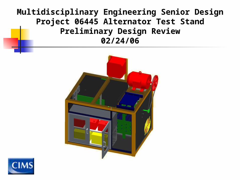
Multidisciplinary Engineering Senior DesignProject 06445 Alternator Test Stand
Preliminary Design Review02/24/06
Sponsor/Mentors/Members
Project SponsorCenter for Integrated Manufacturing Systems
Team Members Aaron Wright - Project Manager Dan Guerand - Mechanical Engineer Kevin Lloyd – Mechanical Engineer Tim Marvin - Mechanical/Electrical Engineer Dave Schuele - Mechanical Engineer
Team Mentors Mike Thurston Omar Anbari Cyril Gaillard Abhijit Mukherjee
Alternator Test Stand Background
CIMS development of Reliability Centered Maintenance
RCM focuses on predicting failure
CIMS would like to predict the failure of military and domestic alternators
Prediction of failure in alternators allows preventative maintenance to save time, money, life, and equipment.
Project Overview

Project Overview
Test Stand Requirements
Apply a load capable of failing an alternator
Failure must occur in an accelerated time frame
Acquire valuable data for life of alternator
Flexible system design
Test stand must be safe to operate
Self-sustaining for life of alternator
Breakdown of Team Process
1. Project sponsor meetings determined needs
2. Assessed member interests
3. Task list compiled
4. Members assigned to tasks based on interests
5. Concepts for each component categorized by task
6. Gantt chart compiled to provide time requirements for tasks
7. Component feasibility determined by budget and physical constraints
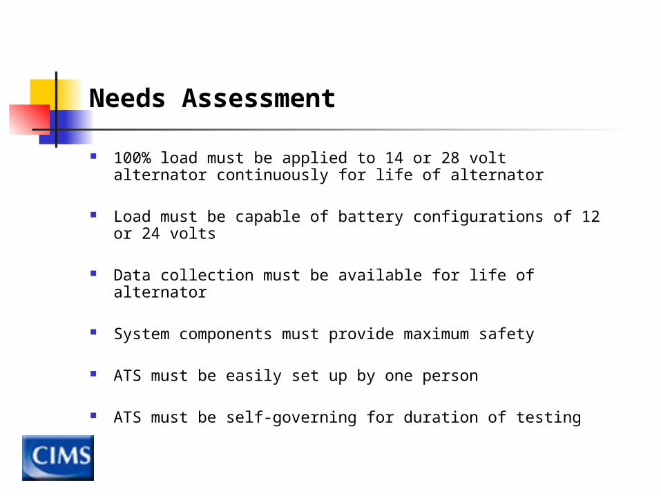
Needs Assessment
100% load must be applied to 14 or 28 volt alternator continuously for life of alternator
Load must be capable of battery configurations of 12 or 24 volts
Data collection must be available for life of alternator
System components must provide maximum safety
ATS must be easily set up by one person
ATS must be self-governing for duration of testing
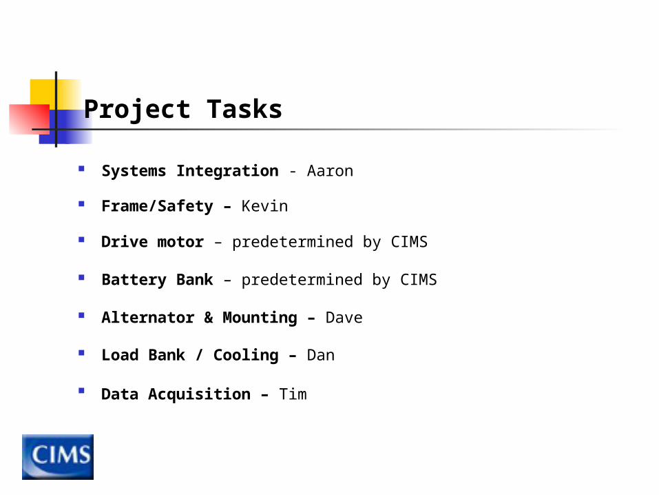
Project Tasks
Systems Integration - Aaron
Frame/Safety – Kevin
Drive motor – predetermined by CIMS
Battery Bank – predetermined by CIMS
Alternator & Mounting – Dave
Load Bank / Cooling – Dan
Data Acquisition – Tim
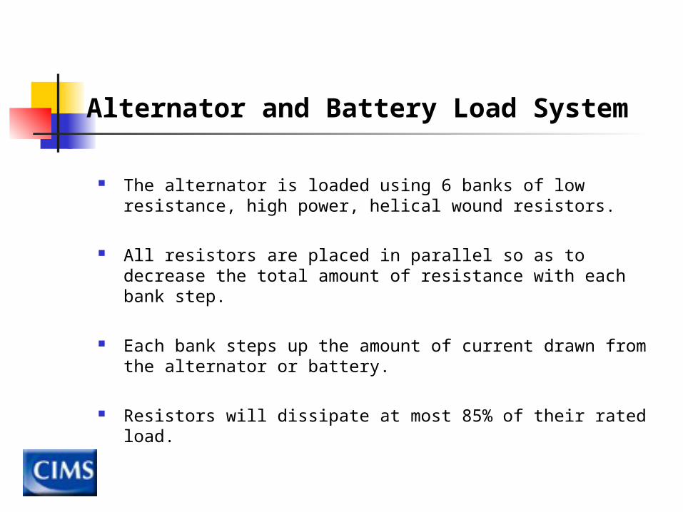
Alternator and Battery Load System
The alternator is loaded using 6 banks of low resistance, high power, helical wound resistors.
All resistors are placed in parallel so as to decrease the total amount of resistance with each bank step.
Each bank steps up the amount of current drawn from the alternator or battery.
Resistors will dissipate at most 85% of their rated load.
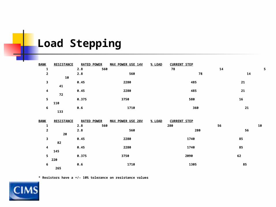
Load Stepping
BANK RESISTANCE RATED POWER MAX POWER USE 14V % LOAD CURRENT STEP 1 2.8 560 78 14 5 2 2.8 560 78 14 10 3 0.45 2280 485 21 41 4 0.45 2280 485 21 72 5 0.375 3750 580 16 110 6 0.6 1710 360 21 133
BANK RESISTANCE RATED POWER MAX POWER USE 28V % LOAD CURRENT STEP 1 2.8 560 280 56 10 2 2.8 560 280 56 20 3 0.45 2280 1740 85 82 4 0.45 2280 1740 85 145 5 0.375 3750 2090 62 220 6 0.6 1710 1305 85 265
* Resistors have a +/- 10% tolerance on resistance values
Thermal System
The thermal system uses forced convection to dissipate the heat
produced by the resistors.
Advantages Allows for heat transfer rates that are much higher than those
for natural convection. Maintains the ambient temperature of the air surrounding the
resistor bank to levels that the resistors can operate within.
Disadvantages Use of fans requires more power to operate the test stand. Mounting and space constraints within the frame.
Varying the Parameters
Staggered array
Air velocity
Number of rows of resistors
Transverse pitch
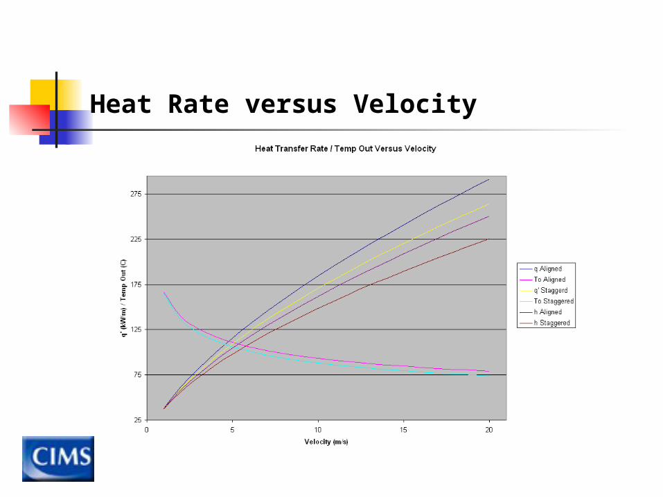
Heat Rate versus Velocity
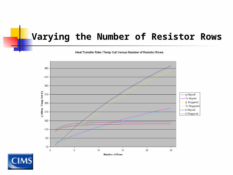
Varying the Number of Resistor Rows
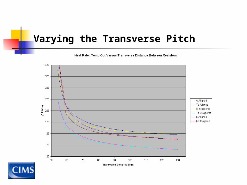
Varying the Transverse Pitch
Amount of Power Dissipation
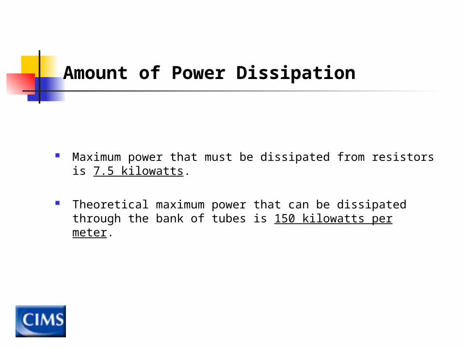
Maximum power that must be dissipated from resistors is 7.5 kilowatts.
Theoretical maximum power that can be dissipated through the bank of tubes is 150 kilowatts per meter.
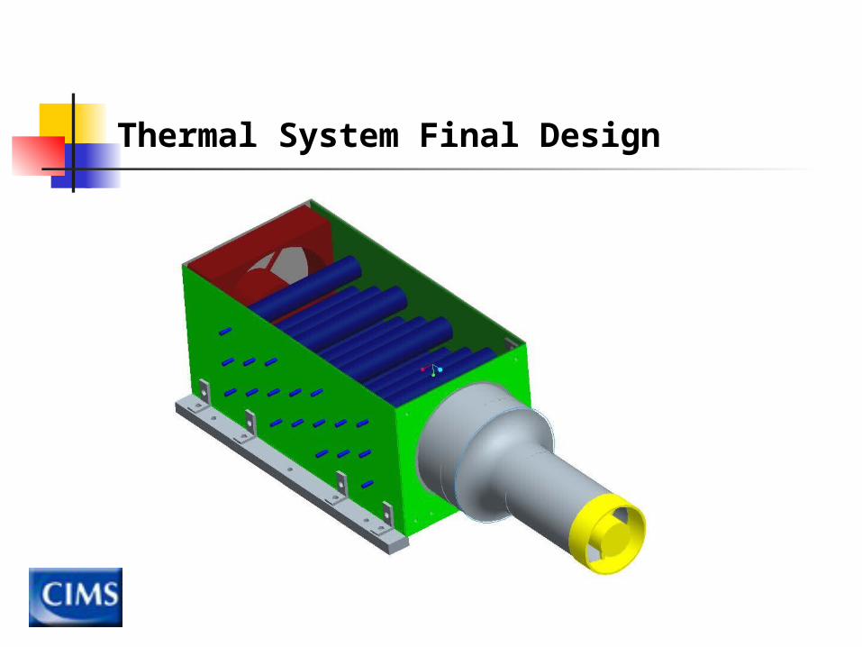
Thermal System Final Design
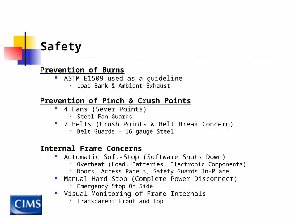
Safety
Prevention of Burns ASTM E1509 used as a guideline
Load Bank & Ambient Exhaust
Prevention of Pinch & Crush Points 4 Fans (Sever Points)
Steel Fan Guards 2 Belts (Crush Points & Belt Break Concern)
Belt Guards – 16 gauge Steel
Internal Frame Concerns Automatic Soft-Stop (Software Shuts Down)
Overheat (Load, Batteries, Electronic Components) Doors, Access Panels, Safety Guards In-Place
Manual Hard Stop (Complete Power Disconnect) Emergency Stop On Side
Visual Monitoring of Frame Internals Transparent Front and Top
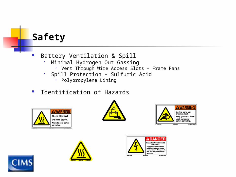
Safety
Battery Ventilation & Spill Minimal Hydrogen Out Gassing
Vent Through Wire Access Slots – Frame Fans Spill Protection – Sulfuric Acid
Polypropylene Lining
Identification of Hazards

Aesthetics
Professional Appearance Specified Placement for Subassemblies Electronic Components Board Bundle & Harness Wires Conceal Rough Edges
Visually Appealing to CIMS Vendors & Customers Display Components
Transparent Front & Top
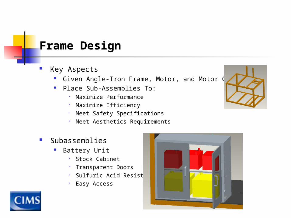
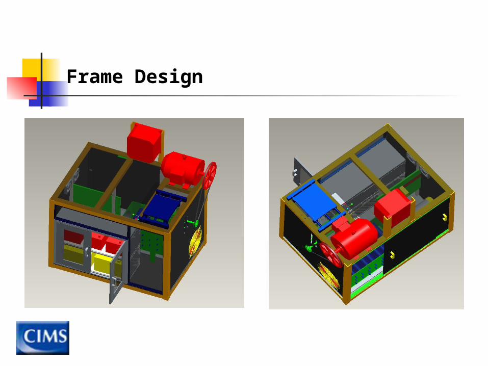
Frame Design
Key Aspects Given Angle-Iron Frame, Motor, and Motor Controller Place Sub-Assemblies To:
Maximize Performance Maximize Efficiency Meet Safety Specifications Meet Aesthetics Requirements
Subassemblies Battery Unit
Stock Cabinet Transparent Doors Sulfuric Acid Resistant Easy Access
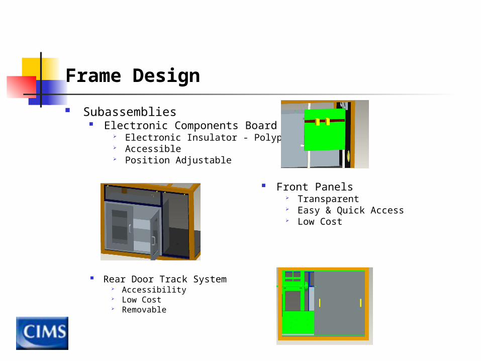
Frame Design
Subassemblies Electronic Components Board
Electronic Insulator - Polypropylene Accessible Position Adjustable
Rear Door Track System Accessibility Low Cost Removable
Front Panels Transparent Easy & Quick Access Low Cost
Frame Design
Other Frame Components Top
Transparent Sealed
Sides Moderately Rigid
Placement Limited Option:
Battery Unit – Front Left Load Bank – Horizontal
Other Components Based on Requirements (Previously Mentioned)
Frame Design
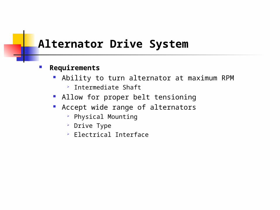
Alternator Drive System
Requirements Ability to turn alternator at maximum RPM
Intermediate Shaft Allow for proper belt tensioning Accept wide range of alternators
Physical Mounting Drive Type Electrical Interface
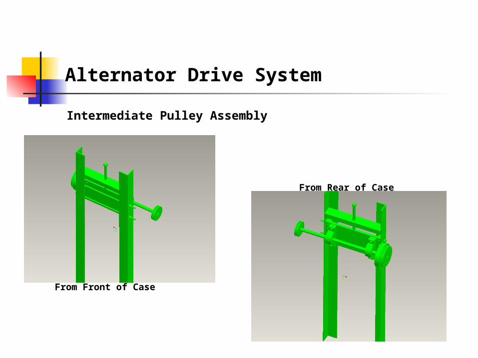
Alternator Drive System
Intermediate Pulley Assembly
From Front of Case
From Rear of Case
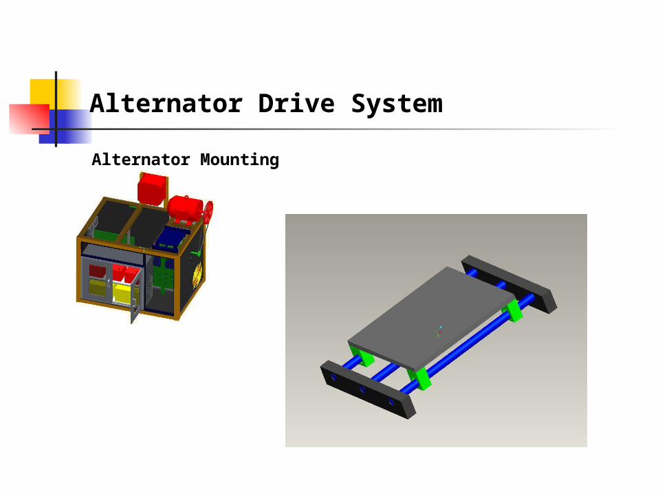
Alternator Drive System
Alternator Mounting
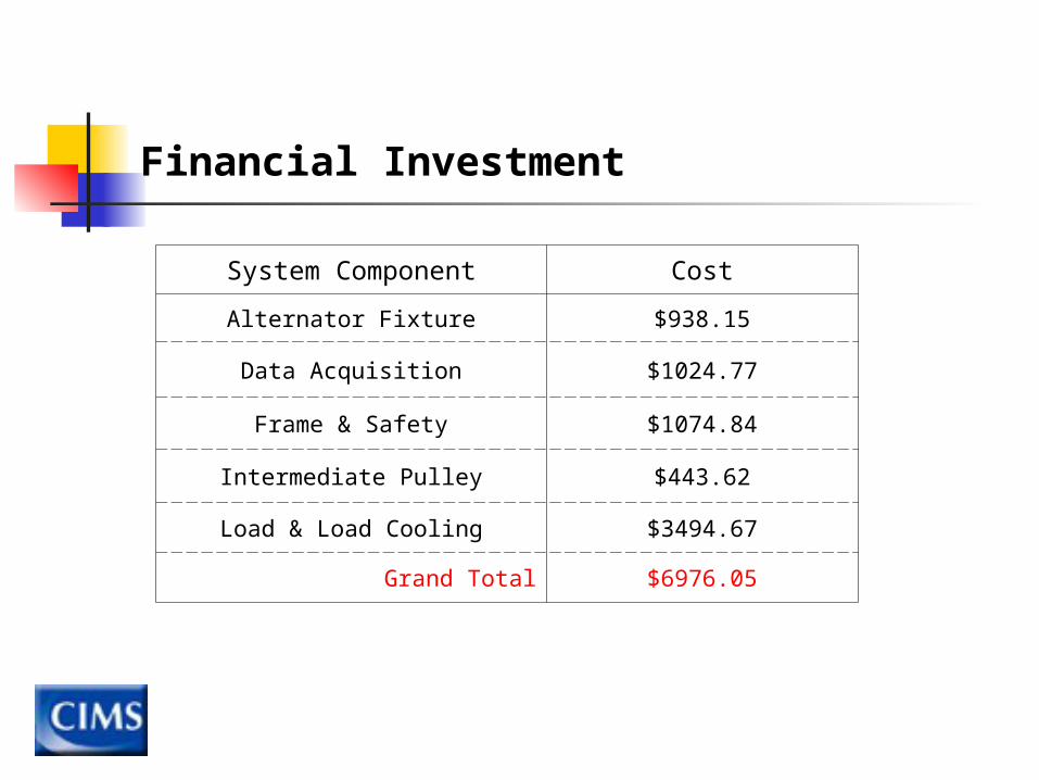
System Component Cost
Alternator Fixture $938.15
Data Acquisition $1024.77
Frame & Safety $1074.84
Intermediate Pulley $443.62
Load & Load Cooling $3494.67
Grand Total $6976.05
Financial Investment

Questions
Backup Slides and References