multidisciplinary considerations in the design of wings
TRANSCRIPT
Brigham Young University Brigham Young University
BYU ScholarsArchive BYU ScholarsArchive
Faculty Publications
2010-3
Multidisciplinary Considerations in the Design of Wings and Wing Multidisciplinary Considerations in the Design of Wings and Wing
Tip Devices Tip Devices
Andrew Ning Brigham Young University - Provo, [email protected]
Ilan Kroo Stanford University
Follow this and additional works at: https://scholarsarchive.byu.edu/facpub
Part of the Mechanical Engineering Commons
BYU ScholarsArchive Citation BYU ScholarsArchive Citation Ning, Andrew and Kroo, Ilan, "Multidisciplinary Considerations in the Design of Wings and Wing Tip Devices" (2010). Faculty Publications. 1629. https://scholarsarchive.byu.edu/facpub/1629
This Peer-Reviewed Article is brought to you for free and open access by BYU ScholarsArchive. It has been accepted for inclusion in Faculty Publications by an authorized administrator of BYU ScholarsArchive. For more information, please contact [email protected], [email protected].
Multidisciplinary Considerations in the Design of
Wings and Wing Tip Devices
S. Andrew Ning
⇤and Ilan Kroo
†
Stanford University, Stanford, CA, 94305
Conceptual wing design analysis methods are combined with numerical optimization to
find minimum drag wings subject to constraints on lift, weight, pitching moment, and stall
speed. Tip extensions and winglets designed for minimum drag achieve similar perfor-
mance, with the optimal solution depending on the ratio of the maneuver lift coe�cient to
the cruise lift coe�cient. The results highlight the importance of accounting for the depth
of the wing structural box in the weight model, and including constraints on stall speed.
For tailless aircraft, C-wings show a slight performance advantage over wings with winglets
when longitudinal trim and stability constraints are considered. This performance advan-
tage is more significant for span-constrained or low sweep designs. Finally, to demonstrate
other possible applications of the method, planar wings with active load alleviation are
optimized, showing drag savings on the order of 15%.
Nomenclature
AR aspect ratiob spanC
L
lift coe�cientc
l
section lift coe�cientC
m
ac
pitching moment coe�cient about the aerodynamic centerC
m
cg
pitching moment coe�cient about the center of gravityc
r
root chordc
t
tip chordD drage span e�ciencyI
b
bending weight indexJ objectiveL lift` lengthM
b
bending momentS wing areas.m. static margint section thicknesst
s
skin thicknessV
s
stall speedW weight
Subscripts
max maximummvr maneuverref reference
⇤Ph.D. Candidate, Department of Aeronautics and Astronautics, AIAA Student Member.†Professor, Department of Aeronautics and Astronautics, AIAA Fellow.
1 of 19
American Institute of Aeronautics and Astronautics
Symbols
⌘
c
spanwise location of lift centroid in units of semi-span� local circulation⇤ quarter chord sweep� taper ratio� dihedral angle⇢ density✓ local twist angle⇠ coordinate tangent to wing
I. Introduction
High fuel costs and environmental concerns provide continuing motivation for research aimed at increasingaircraft e�ciency. Vortex drag is a major contributor to aircraft drag, typically accounting for about 40% ofthe drag in cruise and about 80-90% of the drag in second segment climb.1 Since wing tip geometry stronglya↵ects vortex drag, wing tip optimization has received a great deal of attention. Improved wing tip designcan not only benefit new designs, but can also improve performance of existing wings through retrofits.
One of the early wing tip modifications was a simple end plate.2,3 These end plates were shown toincrease the e↵ective span of the wing, thus reducing the vortex drag. Richard Whitcomb at NASA achievedgreater gains in e�ciency through carefully designed high aspect ratio end plates which he termed winglets.His experimental data published in 1976 showed that a winglet improved the lift to drag ratio by nearly afactor of two as compared to a tip extension.4
Many studies since then, both computation and experimental, compare tip extensions with winglets.5–11
The conclusions di↵er depending on the structural constraint, whether or not viscous drag is included, andthe range of geometries explored. There are several reasons why a reexamination of the relative benefits oftip extensions and winglets is warranted.
First, the structural constraint used in most of these studies is a fixed root bending moment. Rootbending moment does not account for the e↵ect of chordwise changes in the planform on the bending weight.A fixed root bending moment can be especially inappropriate for nonplanar configurations, as large wingletscan be designed with zero or even negative changes in root bending moment. Also, most previous studiesapply the weight constraint at the cruise lift coe�cient (or at some other fixed lift coe�cient). However, theresults are sometimes significantly di↵erent as the critical structural lift coe�cient is varied for a given wingdesign (corresponding to di↵erent critical structural altitudes).
Second, many of these studies compare only induced drag. Including viscous drag can be particularlyimportant when comparing tip extensions with winglets, as the designs often have very di↵erent wettedareas. This is often addressed by keeping the wetted area of the entire wing constant. However, for nonplanarwings, neither fixing the wetted area nor fixing the projected area allows for fair comparisons between designsbecause of tradeo↵s with viscous drag and maximum lift capabilities.
Third, all of these studies analyze a small number of designs, or parametrically vary a few of the designvariables. Wings with tip devices introduce more planform variables than can be handled properly by simpletrade studies. In particular, many of the above mentioned studies use simple linearly extrapolated tipextensions. Such a tip extension is an ine↵ective use of wetted area for the same reason why an end plateis less e↵ective than a winglet. Optimization is employed in some of the previous studies, but is limited tooptimizing the lift distribution only.
This paper seeks to address these concerns, while still retaining simplicity in the analysis methods, asappropriate for conceptual design studies. Certainly, the choice of a tip extension, winglet, or other tip devicedepends upon many other considerations not addressed here such as the e↵ect on the aircraft stability andcontrol, aeroelastics, and even marketing. Our objective in this paper is not to design an airplane, rather weseek to explore fundamental, but complex multidisciplinary considerations in the design of wings and wingtip devices. We will not conclude whether winglets or tip extensions are “better”, as this would require aspecific and complete aircraft design study. Instead, the results show the importance of various assumptionsand design degrees of freedom.
First, tip extensions and winglets are compared using nonlinear optimization. C-wings are then investi-gated to determine if there are significant performance advantages to C-wing designs as compared to wingswith winglets. Finally, as an example of the wider applicability of the method, a planar wing with active
2 of 19
American Institute of Aeronautics and Astronautics
load alleviation is optimized.
II. Method
A. Fundamental Considerations
Wing design involves fundamental tradeo↵s between drag, weight, and stall speed. Fixing the area of thewing is often done to simplify some of the interactions in simple trade studies, but even then the tradeo↵sare not always clear. As a simple example, consider adding a winglet to a wing and increasing its height.If the wetted area of the wing/winglet combination is fixed, then viscous drag and area-dependent weightcan be kept roughly constant while induced drag is reduced. However, the bending weight increases notonly due to the increased height of the winglet, but also due to the smaller chords in the main wing. Inaddition, the projected area decreases resulting in decreased maximum lift capabilities and higher stallsspeeds. Alternatively, the projected area of the wing may be fixed. This will allow for the stall speedperformance to be roughly maintained while induced drag is decreased, but the viscous drag will increase aswill both the area-dependent and load-dependent weight of the wing.
These fundamental tradeo↵s can have complex interactions, especially as the wing design problem includesadditional degrees of freedom. Nonlinear optimization allows the relative benefits of wing designs to beassessed more completely. In this paper we consider wings designed for minimum drag with fixed lift,weight, and stall speed. The methods used for computing drag, weight, and stall speed are outlined below.Validation of the methodology is done by comparing to a variety of analytic solutions,12 as well as to pastnumerical studies.8,13 Parameters such as panel density are chosen to ensure that results are within a percentor two of these known solutions. These results, along with further implementation details, can be found inour previous paper.14
B. Drag Model
This study investigates only low speed wings. For these cases, only vortex drag and viscous drag needto be considered. More realistic configurations would also need to include compressibility drag. Vortex dragis calculated at the Tre↵tz plane by using a drag free wake leaving the trailing edge of the wing planform.Viscous drag is calculated using strip theory by assuming a parabolic variation in viscous drag coe�cientwith section lift coe�cient. Changes in loading with twist and angle of attack are computed using a discretevortex Weissinger model.15 Fifty panels are equally spaced across the wing semi-span. The methodology issimilar to that used by Kroo.8
C. Weight Model
The wing weight is decomposed into a part due to the load, and a part due to the size of the wing. Area-dependent variations in wing weight are particularly important to consider for nonplanar configurations.
W = W
load
+W
area
The load dependent weight is assumed to be proportional to the volume of material required to support a fullystressed wing in bending (a good approximation for wings of moderate to high aspect ratios where di↵erencesin shear-dependent weight are negligible, and for wings with low to moderate sweep where di↵erences intorsion-dependent weight are negligible), and that the area-dependent weight is proportional to the grossarea of the wing. The load dependent weight is given by
I
b
=
Z |Mb
|t
ds
which is integrated along the main structural spar. Wing weight is then given by
W = k1Ib + k2S
where k1 and k2 are appropriately chosen constants. In this paper we are only interested in computing theratio of weight to the reference weight, which leaves only one undetermined coe�cient.
W
W
ref
=k1Ib + k2S
k1Ibref
+ k2Sref
=I
b
+ k
W
S
I
b
ref
+ k
W
S
ref
3 of 19
American Institute of Aeronautics and Astronautics
where kW
= k2/k1. The value of this constant was determined by correlating aircraft data with the bendingindex used here (k
W
= 3.57⇥ 104).It should be mentioned that the value for wing weight does not represent an actual dimensional wing
weight, but is intended to scale appropriately with changes in wing planform and aerodynamic loading inorder to compare the wing weight of di↵erent designs. A wing weight estimate of this form has been shownto correlate well with the wing weight data from actual transport aircraft.a
One additional modification is made to the weight computation to account for the di↵erence in cruiseloading and critical structural loading. Here, we assume that the aircraft is maneuver critical rather thangust critical. In this case the maximum load factor may be the same for many di↵erent aircraft, but thecritical structural altitude will vary. This means that the maneuver lift coe�cient (at which the bendingweight is computed) must be allowed to be di↵erent from the cruise lift coe�cient. For a given geometry, theload dependent weight index can be shown to be a function only of the ratio of the maneuver lift coe�cientto the cruise lift coe�cient.14
The ratio C
L
mvr
/C
L
relates the critical structural altitude to the cruise altitude. For wider applicabilityof the results, cases are shown for C
L
mvr
/C
L
equal to 1 and 2.5. As a specific example, and that used in thispaper, assume a fixed load factor of 2.5 (many transport aircraft have their maximum maneuver load factorset at 2.5 as per FAR Part 2516). Then, if the cruise altitude of the aircraft is 35,000 ft, C
L
mvr
/C
L
= 2.5corresponds to a critical structural altitude of 35,000 ft, whereas C
L
mvr
/C
L
= 1 corresponds to a criticalstructural altitude of 14,000 ft at fixed Mach number. Thus, the choice of these two values is meant tocapture di↵erences in designs over a wide range of critical structural altitudes.
While wing bending loads are clearly important, a more complete configuration study would also need toconsider other structural loading conditions such as those provided by inertial relief, taxi-bump, etc. Relatedconstraints such as fuel volume requirements, and ground strike deflection would also be important in thestructural design. Most of these considerations require detailed information about mass properties, fueldistributions, and performance requirements appropriate for a specific aircraft design study. However, thepurpose of this paper is to emphasize the fundamental tradeo↵s between load distribution, weight, and drag.The metric used here for wing weight is only intended to capture the dominant e↵ects of wing planform andaerodynamic loading changes on wing weight.
D. Stall Speed Model
Stall speed is given by
V
s
=
s2L
⇢SC
L
max
A constraint on stall speed is important when optimizing the planform geometry. Without this constraint,optimization often leads to unrealistically small tip chords with high section lift coe�cients. All designs arerequired to have a stall speed less than or equal to that of the reference wing. Since the lift is fixed, thisgives the inequality constraint C
L
max
S � (CL
max
S )|ref
.C
L
max
is di�cult to predict and is really a three dimensional, unsteady, viscous phenomena. Consistentwith the simplicity of the aero/structural model, C
L
max
is estimated simply from critical section theory.Essentially, this means that stall is predicted when any one section of the wing reaches a specified sectionc
l
max
. Since no high-lift devices are modeled, the clean wing stall speed is constrained.This constraint on stall speed is not directly imposed in the optimization problem. For a given wing area
the required C
L
max
can be found directly from the constraint C
L
max
S � (CL
max
S )|ref
. The constraintimposed in the optimization problem is that at the required C
L
max
the c
l
distribution must be everywhereless than or equal to a specified maximum section lift coe�cient ({c
l
} |C
L
max
{cl
max
}.). In the resultsshown in this paper the vector {c
l
max
} is constant across the wing for simplicity in discussing the results.
E. Optimization
There are three basic approaches to this optimization problem, each of increasing complexity over theprevious. The first is the method of restricted variations. This method allows for analytic solutions ofoptimal normalwash distributions by considering small perturbations to the lift distribution. Considerationfor parasitic drag, section lift coe�cient constraints, and weight constraints can even be included. The
ahttp://adg.stanford.edu/aa241/AircraftDesign.html (see Component Weights section)
4 of 19
American Institute of Aeronautics and Astronautics
analytic solutions allow for good insight, but the method is restricted to simple geometries with simpleformulations for the objective and constraints.
The second option also optimizes the lift distribution, but can allow for more complex geometries andconstraints. Under the assumptions of the Prandtl-Glauert equation, the optimization can be posed as aquadratic programming problem. If only equality constraints are included, like lift and weight, then optimalloading is given directly by solving a linear system of equations. This approach has been used many times inthe past.8,11,17 This method is good for giving insight into the e↵ect of di↵erent weight models, comparingresults with and without viscous drag, and for performing trade studies with planform variations. The rapidnature of the load optimization problem allows for trades studies with a fairly large number of wing designs.
The method may also be extended by including linear inequality constraints like stall speed. In thesecases the optimization problem is still a convex quadratic programming problem which is easily solved. Thisapproach has been pursued in some of our past studies.14
The third option, and the one used in this paper, is to also include all the planform parameters asdesign variables. In this case, the objective and constraints are nonlinear functions of the design variables.However, the functions are still smooth allowing for gradient based methods. Furthermore, the sensitivitiesof the objective and constraints to the additional design variables are approximated quite well by piecewiselinear functions over a broad range of step sizes, allowing for robust and quick convergence using finitedi↵erences. The results shown in this paper are all solved using the sequential quadratic programmingmethod.
III. Nonlinear Planform Optimization
Four di↵erent optimization cases are presented: tip geometry for a retrofitted wing, tip geometry for anoptimized wing, C-wings with stability and trim constraints, and planar wings with active load alleviation.We emphasize again that the results are intended to explore the e↵ect of multidisciplinary considerations inwing design, they are not intended to represent complete configuration design studies.
A. Tip Extensions and Winglets - Retrofit
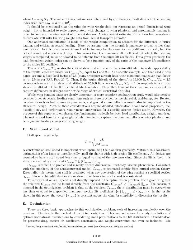
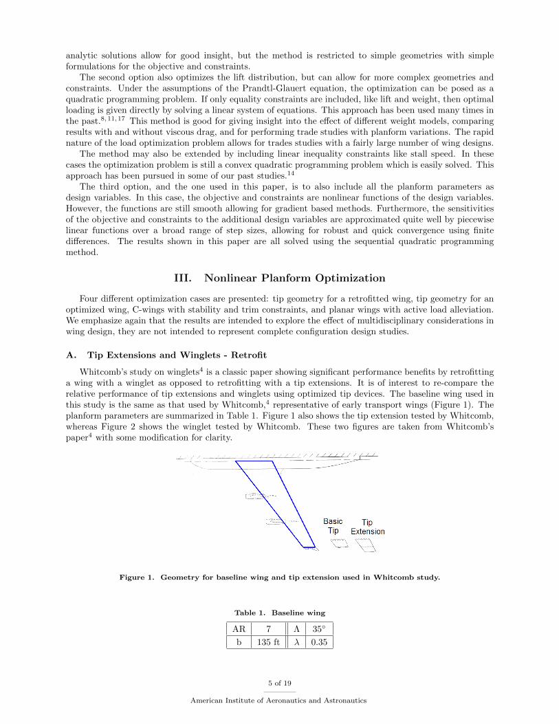
Whitcomb’s study on winglets4 is a classic paper showing significant performance benefits by retrofittinga wing with a winglet as opposed to retrofitting with a tip extensions. It is of interest to re-compare therelative performance of tip extensions and winglets using optimized tip devices. The baseline wing used inthis study is the same as that used by Whitcomb,4 representative of early transport wings (Figure 1). Theplanform parameters are summarized in Table 1. Figure 1 also shows the tip extension tested by Whitcomb,whereas Figure 2 shows the winglet tested by Whitcomb. These two figures are taken from Whitcomb’spaper4 with some modification for clarity.
Figure 1. Geometry for baseline wing and tip extension used in Whitcomb study.
Table 1. Baseline wing
AR 7 ⇤ 35�
b 135 ft � 0.35
5 of 19
American Institute of Aeronautics and Astronautics
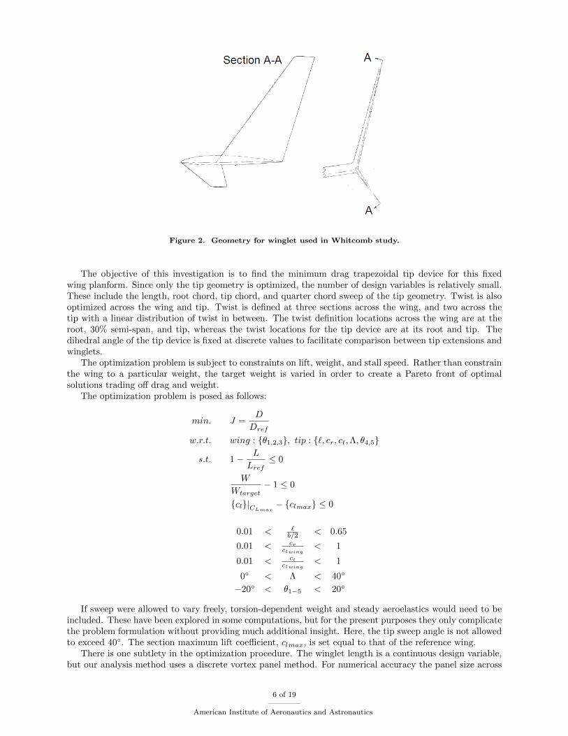
Figure 2. Geometry for winglet used in Whitcomb study.
The objective of this investigation is to find the minimum drag trapezoidal tip device for this fixedwing planform. Since only the tip geometry is optimized, the number of design variables is relatively small.These include the length, root chord, tip chord, and quarter chord sweep of the tip geometry. Twist is alsooptimized across the wing and tip. Twist is defined at three sections across the wing, and two across thetip with a linear distribution of twist in between. The twist definition locations across the wing are at theroot, 30% semi-span, and tip, whereas the twist locations for the tip device are at its root and tip. Thedihedral angle of the tip device is fixed at discrete values to facilitate comparison between tip extensions andwinglets.
The optimization problem is subject to constraints on lift, weight, and stall speed. Rather than constrainthe wing to a particular weight, the target weight is varied in order to create a Pareto front of optimalsolutions trading o↵ drag and weight.
The optimization problem is posed as follows:
min. J =D
D
ref
w.r.t. wing : {✓1,2,3}, tip : {`, cr
, c
t
,⇤, ✓4,5}
s.t. 1� L
L
ref
0
W
W
target
� 1 0
{cl
}|C
L
max
� {cl
max
} 0
0.01 <
`
b/2 < 0.65
0.01 <
c
r
c
t
wing
< 1
0.01 <
c
t
c
t
wing
< 1
0� < ⇤ < 40�
�20� < ✓1�5 < 20�
If sweep were allowed to vary freely, torsion-dependent weight and steady aeroelastics would need to beincluded. These have been explored in some computations, but for the present purposes they only complicatethe problem formulation without providing much additional insight. Here, the tip sweep angle is not allowedto exceed 40�. The section maximum lift coe�cient, c
l
max
, is set equal to that of the reference wing.There is one subtlety in the optimization procedure. The winglet length is a continuous design variable,
but our analysis method uses a discrete vortex panel method. For numerical accuracy the panel size across
6 of 19
American Institute of Aeronautics and Astronautics
the wing and tip is held constant. However, with a fixed panel size, the number of panels on the tip willvary discontinuously. This is a problem for gradient based optimization, but is resolved by varying the tiplength parametrically.
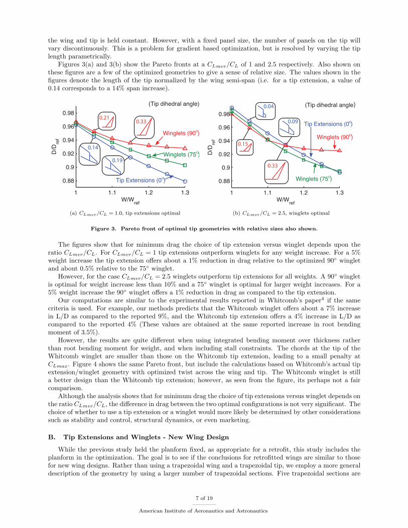
Figures 3(a) and 3(b) show the Pareto fronts at a C
L
mvr
/C
L
of 1 and 2.5 respectively. Also shown onthese figures are a few of the optimized geometries to give a sense of relative size. The values shown in thefigures denote the length of the tip normalized by the wing semi-span (i.e. for a tip extension, a value of0.14 corresponds to a 14% span increase).
1 1.1 1.2 1.3
0.88
0.9
0.92
0.94
0.96
0.98
W/Wref
D/D
ref
(Tip dihedral angle)
Winglets (75ο)
Winglets (90ο)
Tip Extensions (0ο)
0.14
0.19
0.210.33
(a) CL
mvr
/CL
= 1.0, tip extensions optimal
1 1.1 1.2 1.3
0.88
0.9
0.92
0.94
0.96
0.98
W/Wref
D/D
ref
(Tip dihedral angle)
Winglets (90ο)
Tip Extensions (0ο)
Winglets (75ο)
)
0.09
0.04
0.33
0.15
(b) CL
mvr
/CL
= 2.5, winglets optimal
Figure 3. Pareto front of optimal tip geometries with relative sizes also shown.
The figures show that for minimum drag the choice of tip extension versus winglet depends upon theratio C
L
mvr
/C
L
. For CL
mvr
/C
L
= 1 tip extensions outperform winglets for any weight increase. For a 5%weight increase the tip extension o↵ers about a 1% reduction in drag relative to the optimized 90� wingletand about 0.5% relative to the 75� winglet.
However, for the case C
L
mvr
/C
L
= 2.5 winglets outperform tip extensions for all weights. A 90� wingletis optimal for weight increase less than 10% and a 75� winglet is optimal for larger weight increases. For a5% weight increase the 90� winglet o↵ers a 1% reduction in drag as compared to the tip extension.
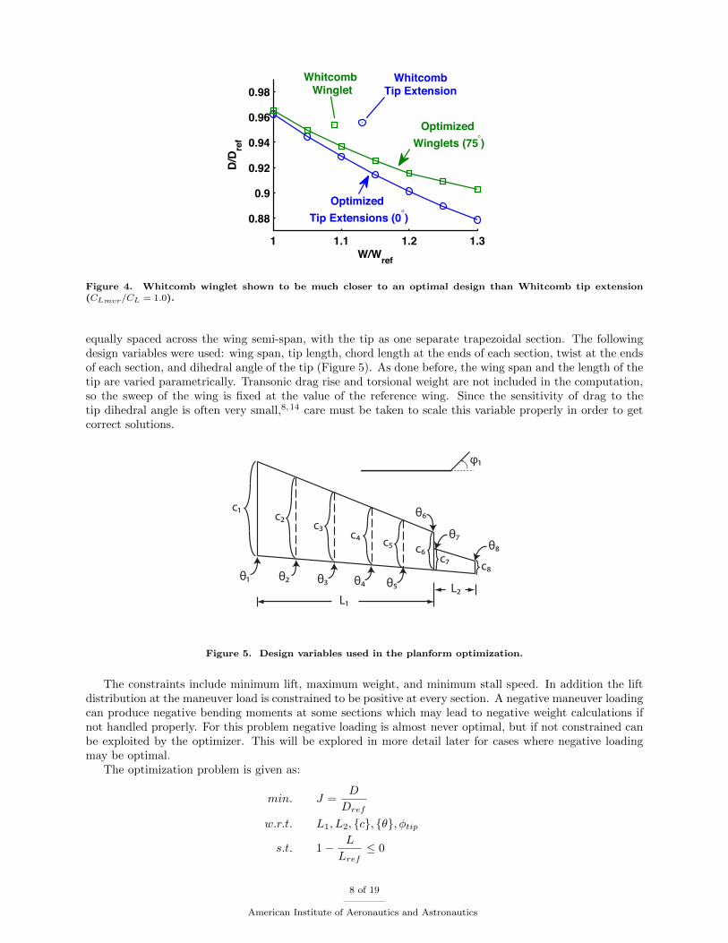
Our computations are similar to the experimental results reported in Whitcomb’s paper4 if the samecriteria is used. For example, our methods predicts that the Whitcomb winglet o↵ers about a 7% increasein L/D as compared to the reported 9%, and the Whitcomb tip extension o↵ers a 4% increase in L/D ascompared to the reported 4% (These values are obtained at the same reported increase in root bendingmoment of 3.5%).
However, the results are quite di↵erent when using integrated bending moment over thickness ratherthan root bending moment for weight, and when including stall constraints. The chords at the tip of theWhitcomb winglet are smaller than those on the Whitcomb tip extension, leading to a small penalty atC
L
max
. Figure 4 shows the same Pareto front, but include the calculations based on Whitcomb’s actual tipextension/winglet geometry with optimized twist across the wing and tip. The Whitcomb winglet is stilla better design than the Whitcomb tip extension; however, as seen from the figure, its perhaps not a faircomparison.
Although the analysis shows that for minimum drag the choice of tip extensions versus winglet depends onthe ratio C
L
mvr
/C
L
, the di↵erence in drag between the two optimal configurations is not very significant. Thechoice of whether to use a tip extension or a winglet would more likely be determined by other considerationssuch as stability and control, structural dynamics, or even marketing.
B. Tip Extensions and Winglets - New Wing Design
While the previous study held the planform fixed, as appropriate for a retrofit, this study includes theplanform in the optimization. The goal is to see if the conclusions for retrofitted wings are similar to thosefor new wing designs. Rather than using a trapezoidal wing and a trapezoidal tip, we employ a more generaldescription of the geometry by using a larger number of trapezoidal sections. Five trapezoidal sections are
7 of 19
American Institute of Aeronautics and Astronautics
1 1.1 1.2 1.3
0.88
0.9
0.92
0.94
0.96
0.98
W/Wref
D/D
ref
WhitcombTip Extension
Whitcomb Winglet
Optimized Winglets (75°)
Optimized Tip Extensions (0°)
Figure 4. Whitcomb winglet shown to be much closer to an optimal design than Whitcomb tip extension(C
L
mvr
/CL
= 1.0).
equally spaced across the wing semi-span, with the tip as one separate trapezoidal section. The followingdesign variables were used: wing span, tip length, chord length at the ends of each section, twist at the endsof each section, and dihedral angle of the tip (Figure 5). As done before, the wing span and the length of thetip are varied parametrically. Transonic drag rise and torsional weight are not included in the computation,so the sweep of the wing is fixed at the value of the reference wing. Since the sensitivity of drag to thetip dihedral angle is often very small,8,14 care must be taken to scale this variable properly in order to getcorrect solutions.
φ1
θ1 θ2 θ3 θ4 θ5
θ6
θ7θ8
c1c2
c3c4
c5c6
c7c8
L1L2
Figure 5. Design variables used in the planform optimization.
The constraints include minimum lift, maximum weight, and minimum stall speed. In addition the liftdistribution at the maneuver load is constrained to be positive at every section. A negative maneuver loadingcan produce negative bending moments at some sections which may lead to negative weight calculations ifnot handled properly. For this problem negative loading is almost never optimal, but if not constrained canbe exploited by the optimizer. This will be explored in more detail later for cases where negative loadingmay be optimal.
The optimization problem is given as:
min. J =D
D
ref
w.r.t. L1, L2, {c}, {✓},�tip
s.t. 1� L
L
ref
0
8 of 19
American Institute of Aeronautics and Astronautics
W
W
ref
� 1 0
{cl
}|C
L
max
� {cl
max
} 0
{�mvr
}�
ref
� 0
0.5 <
L1b
ref
< 2
0.01 <
L2b
ref
< 0.5
0.01 <
c
c
ref
< 5
�20� < ✓ < 20�
0�
1000 <
�
tip
1000 <
120�
1000
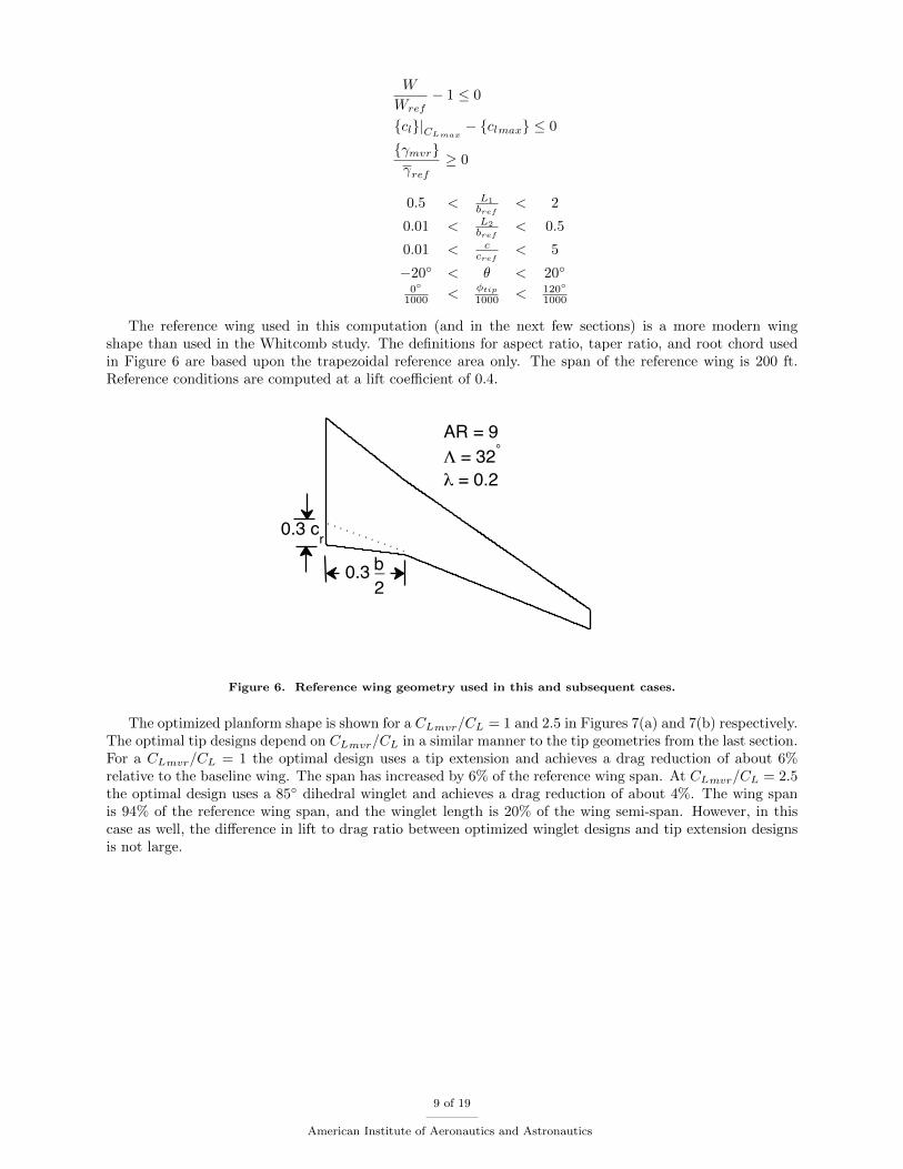
The reference wing used in this computation (and in the next few sections) is a more modern wingshape than used in the Whitcomb study. The definitions for aspect ratio, taper ratio, and root chord usedin Figure 6 are based upon the trapezoidal reference area only. The span of the reference wing is 200 ft.Reference conditions are computed at a lift coe�cient of 0.4.
AR = 9Λ = 32°
λ = 0.2
0.3 cr
2b_0.3
Figure 6. Reference wing geometry used in this and subsequent cases.
The optimized planform shape is shown for a C
L
mvr
/C
L
= 1 and 2.5 in Figures 7(a) and 7(b) respectively.The optimal tip designs depend on C
L
mvr
/C
L
in a similar manner to the tip geometries from the last section.For a C
L
mvr
/C
L
= 1 the optimal design uses a tip extension and achieves a drag reduction of about 6%relative to the baseline wing. The span has increased by 6% of the reference wing span. At C
L
mvr
/C
L
= 2.5the optimal design uses a 85� dihedral winglet and achieves a drag reduction of about 4%. The wing spanis 94% of the reference wing span, and the winglet length is 20% of the wing semi-span. However, in thiscase as well, the di↵erence in lift to drag ratio between optimized winglet designs and tip extension designsis not large.
9 of 19
American Institute of Aeronautics and Astronautics
Reference Wing
Optimized Wing
(a) CL
mvr
/CL
= 1.0, tip extension optimal, D/Dref
= 0.94 (b) CL
mvr
/CL
= 2.5, winglet optimal, D/Dref
= 0.96
Figure 7. Optimized wing and tip geometries.
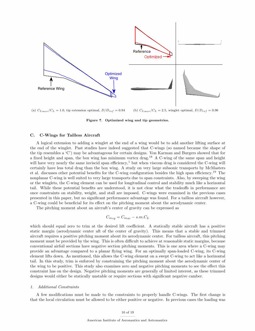
C. C-Wings for Tailless Aircraft
A logical extension to adding a winglet at the end of a wing would be to add another lifting surface atthe end of the winglet. Past studies have indeed suggested that C-wings (so named because the shape ofthe tip resembles a ‘C’) may be advantageous for certain designs. Von Karman and Burgers showed that fora fixed height and span, the box wing has minimum vortex drag.18 A C-wing of the same span and heightwill have very nearly the same inviscid span e�ciency,1 but when viscous drag is considered the C-wing willcertainly have less total drag than the box wing. A study on very large subsonic transports by McMasterset al. discusses other potential benefits for the C-wing configuration besides the high span e�ciency.19 Thenonplanar C-wing is well suited to very large transports due to span constraints. Also, by sweeping the wingor the winglets, the C-wing element can be used for longitudinal control and stability much like a horizontaltail. While these potential benefits are understood, it is not clear what the tradeo↵s in performance areonce constraints on stability, weight, and stall are imposed. C-wings were examined in the previous casespresented in this paper, but no significant performance advantage was found. For a tailless aircraft however,a C-wing could be beneficial for its e↵ect on the pitching moment about the aerodynamic center.
The pitching moment about an aircraft’s center of gravity can be expressed as
C
m
cg
= C
m
ac
� s.m.C
L
which should equal zero to trim at the desired lift coe�cient. A statically stable aircraft has a positivestatic margin (aerodynamic center aft of the center of gravity). This means that a stable and trimmedaircraft requires a positive pitching moment about its aerodynamic center. For tailless aircraft, this pitchingmoment must be provided by the wing. This is often di�cult to achieve at reasonable static margins, becauseconventional airfoil sections have negative section pitching moments. This is one area where a C-wing mayprovide an advantage compared to a planar flying wing. For an optimally span-loaded C-wing, its C-wingelement lifts down. As mentioned, this allows the C-wing element on a swept C-wing to act like a horizontaltail. In this study, trim is enforced by constraining the pitching moment about the aerodynamic center ofthe wing to be positive. This study also examines zero and negative pitching moments to see the e↵ect thisconstraint has on the design. Negative pitching moments are generally of limited interest, as these trimmeddesigns would either be statically unstable or require sections with significant negative camber.
1. Additional Constraints
A few modifications must be made to the constraints to properly handle C-wings. The first change isthat the local circulation must be allowed to be either positive or negative. In previous cases the loading was
10 of 19
American Institute of Aeronautics and Astronautics
always constrained to be positive across the wing at the maneuver load. Allowing the loading to be negativeintroduces several modifications to the constraints.
Negative loading means that the bending moment may be negative at some sections of the wing. Thismust not lead to negative weight, since the volume of material used to resist bending actually dependson the absolute value of the bending moment. Since we are using a gradient based optimization method,using absolute value is problematic as it leads to discontinuous gradients. This can be avoided, but leadsto additional constraints. The number of necessary constraints is reduced by using the observation thatnegative bending moments will typically only occur near the tip of the wing. Thus, the computation of thebending weight is split into a part due to the inner sections of the wing, and a part due to the outer panels.Since the sign of the bending moment on the outer panels is not known a priori, all possible combinationsmust be considered. These combinations are put in a vector where the actual bending weight contributionfrom the outer panels will be the maximum entry in the vector.
W
b
= I
b
inner
+max{Ib
}outer
Including area dependent weight, the weight constraint is now
I
b
inner
+ {Ib
}outer
+ k
W
S W
ref
A skin thickness constraint is necessary because the optimizer would like to unload the winglet, anddrive the winglet to very small chords to reduce drag and weight. But to structurally support the C-wingelement this would require very large skin thicknesses in the winglet. The structural model assumes that theskin thickness is much smaller than the airfoil thickness. The skin thickness of the structural box must beconstrained to prevent unreasonable designs. The skin thickness is restricted to less than 10% of the localsection thickness.
{ts
} 0.1{t}
Both skin thickness and section lift coe�cients depend on the absolute value of the bending moment. Theseconstraints are broken up into two parts to avoid the use of absolute value.
The final modification used for optimizing C-wing designs is related to the maneuver lift coe�cient.Instead of specifying one critical maneuver lift coe�cient at a time, as done in the previous cases, the weightis computed at two di↵erent maneuver lift coe�cients and the weight is taken to be the maximum of thetwo. More details on the implementation of the constraints are available in an earlier version of this paper.14
2. Weight-Constrained Designs
For the optimization problem the wing is divided into five trapezoidal sections, one vertical winglet, andone horizontal C-wing element. The design variables include the wing span, the chord lengths at the ends ofeach section, and the twist at the ends of each section. Since the length of each lifting surface must be variedparametrically, as explained previously, the number of design combinations can become very large. Ratherthan exhaustively explore this design space, we specify a fixed winglet height and fixed C-wing elementlength, both 16% of the wing semi-span. This is a typical height for many modern winglets. The sweep ofthe main wing is fixed at 32� and the sweep of the winglet and C-wing element are both fixed at 20�. Theoptimization problem is given as follows:
min. J =D
D
ref
w.r.t. b, {c}, {✓}
s.t. 1� L
L
ref
0
(Ib
inner
+ {Ib
}outer
+ k
W
S)C
L1
W
ref
� 1 0
(Ib
inner
+ {Ib
}outer
+ k
W
S)C
L2
W
ref
� 1 0
{cl
}|C
L
max
� {cl
max
} 0
11 of 19
American Institute of Aeronautics and Astronautics
� {cl
}|C
L
max
� {cl
max
} 0
{ts
}|C
L1� 0.1{t} 0
{ts
}|C
L2� 0.1{t} 0
�{ts
}outer
|C
L1� 0.1{t} 0
�{ts
}outer
|C
L2� 0.1{t} 0
C
m
ac
� C
m
ac
target
= 0
0.5 <
b
b
ref
< 5
0.01 <
c
c
ref
< 5
�20� < ✓ < 20�
Three di↵erent constraints on pitching moment about the aircraft aerodynamic center are explored:C
m
ac
target
= +0.1, 0,�0.1. As mentioned, typically a positive C
m
ac
is desirable. A C
m
ac
of +0.1, forexample, would allow a flying wing with symmetric sections and a total lift coe�cient of 1 to trim with astatic margin of 10%, or a cambered section flying wing with section pitching moments of -0.1 to trim withzero static margin. This analysis assumes symmetric sections for simplicity.
For each target Cm
ac
, the optimal C-wing is compared to an optimized wing with winglet and an opti-mized wing subject to the same constraints. The minimum drag solution for each configuration is shown inTable 2 normalized by the drag of the reference wing. Table 3 lists the optimized span of each configurationnormalized by the span of the reference wing. The reference wing in these cases is the same as in the previoussection (Figure 6).
Table 2. Relative drag (D/Dref
) of optimized configurations - weight constrained, trimmed
C
m
ac
Wing Wing + Winglet C-wing
+0.1 1.091 1.095 1.081
0 0.978 0.964 0.971
-0.1 1.345 1.316 1.321
Table 3. Relative spans (b/bref
) of optimized configurations - weight constrained, trimmed
C
m
ac
Wing Wing + Winglet C-wing
+0.1 1.078 1.076 0.977
0 1.00 0.956 0.947
-0.1 0.959 0.907 0.902
Table 2 shows that trimming a tailless aircraft has a profound e↵ect on the drag. This can be seenquite easily from a simple analysis relating the lift centroid to the minimum induced drag of the wing. Anelliptically loaded wing has a lift centroid at 42.4% semi-span. For a swept back wing, shifting the liftcentroid inboard would provide a greater pitching moment about the aerodynamic center. The new locationof the lift centroid relative to the elliptic wing would be
⌘
c
= 0.424� �y
b/2
= 0.424� 2�x
b tan⇤
Then relating the change in streamwise shift in lift centroid to the change in pitching moment about theaerodynamic center (�C
m
ac
= �x
c
C
L
)
⌘
c
= 0.424� �C
m
ac
C
L
2c
b tan⇤
12 of 19
American Institute of Aeronautics and Astronautics
= 0.424� �C
m
ac
C
L
2
AR tan⇤
If we let �C
m
ac
= 0.1, CL
= 0.4, AR = 9, and ⇤ = 32� the lift centroid is now ⌘
c
= 0.335.The minimum induced drag for a given lift and location of the lift centroid is given by12
e
inviscid
=
9
2⇡
2⌘
2c
� 12⇡⌘c
+ 9
��1
which for the present example gives einviscid
= 0.74. This corresponds to a 35% increase in induced drag orroughly a 17% increase in total drag, just due to trimming the aircraft.
This rough estimate is consistent with the large drag di↵erence between trimming at C
m
ac
= 0, andtrimming at C
m
ac
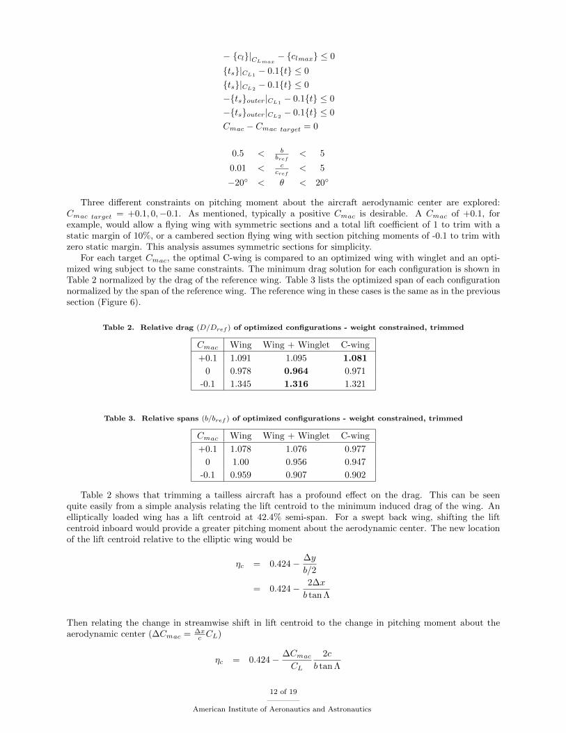
= 0.1. For the later case, however the C-wing provides a small drag advantage. It hasabout 1% less drag, and a 9% smaller span relative to the optimized wing. The geometry for the optimizedC-wing is shown in Figure 8(a). The winglet and C-wing element however, have small chords which requireadditional assessment of the structural dynamics. The lift distributions for this design is shown in Figure 8(b).The coordinate ⇠ traverses the wing tangentially, and the sign convention for positive section c
l
is definedby having positive circulation point in the same direction everywhere on the wing. As expected, the C-wingelement is lifting downward (positive section c
l
) The pitching moment constraint is met by shifting the loadfar inboard, although the C-wing element does provide some nose-up pitching moment.
(a) Wing geometry
0 0.2 0.4 0.6
0
0.5
1
1.5
ξ / b
c
l
c
c̄
C−wingelement
winglet
CL
2.5 CL
elliptic
(b) Lift distribution at cruise lift coe�cient and at 2.5 timescruise lift coe�cient.
Figure 8. Optimized wing for tailless aircraft (C-wing) with positive pitching moment about the aerodynamiccenter constraint (C
m
ac
= +0.1).
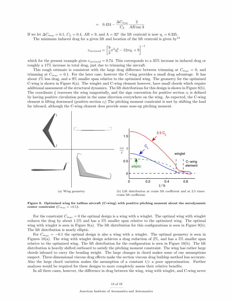
For the constraint Cm
ac
= 0 the optimal design is a wing with a winglet. The optimal wing with wingletreduces the drag by about 1.5% and has a 5% smaller span relative to the optimized wing. The optimalwing with winglet is seen in Figure 9(a). The lift distribution for this configurations is seen in Figure 9(b).The lift distribution is nearly elliptic.
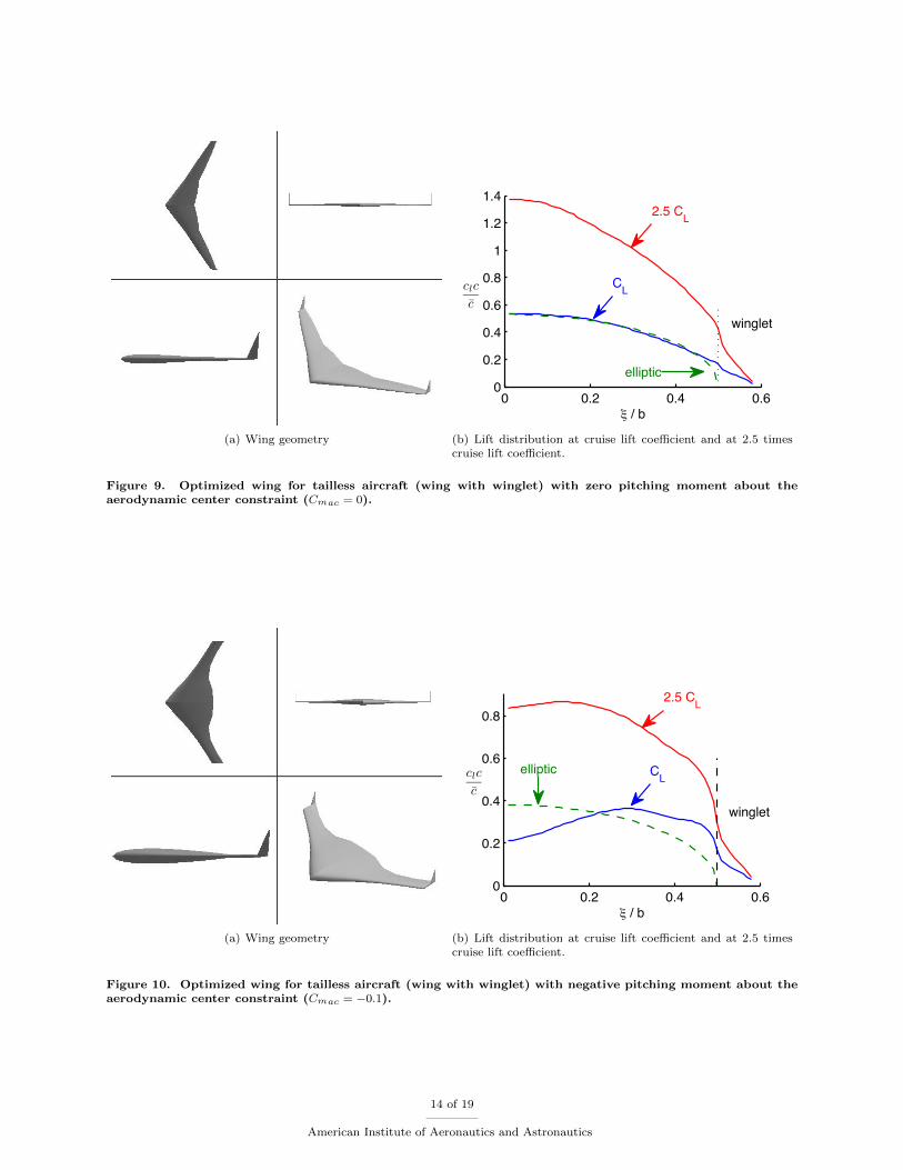
For C
m
ac
= �0.1 the optimal design is also a wing with a winglet. The optimal geometry is seen inFigures 10(a). The wing with winglet design achieves a drag reduction of 2%, and has a 5% smaller spanrelative to the optimized wing. The lift distribution for the configuration is seen in Figure 10(b). The liftdistribution is heavily shifted outboard to satisfy the pitching moment constraint. The wing has rather largechords inboard to carry the bending weight. The large changes in chord makes some of our assumptionssuspect. Three-dimensional viscous drag e↵ects make the section viscous drag buildup method less accurate.Also the large chord variation makes the assumption of a constant t/c a poor approximation. Furtheranalyses would be required for these designs to more completely assess their relative benefits.
In all three cases, however, the di↵erence in drag between the wing, wing with winglet, and C-wing never
13 of 19
American Institute of Aeronautics and Astronautics
(a) Wing geometry
0 0.2 0.4 0.60
0.2
0.4
0.6
0.8
1
1.2
1.4
ξ / b
c
l
c
c̄
2.5 CL
elliptic
winglet
CL
(b) Lift distribution at cruise lift coe�cient and at 2.5 timescruise lift coe�cient.
Figure 9. Optimized wing for tailless aircraft (wing with winglet) with zero pitching moment about theaerodynamic center constraint (C
m
ac
= 0).
(a) Wing geometry
0 0.2 0.4 0.60
0.2
0.4
0.6
0.8
ξ / b
c
l
c
c̄
winglet
2.5 CL
CLelliptic
(b) Lift distribution at cruise lift coe�cient and at 2.5 timescruise lift coe�cient.
Figure 10. Optimized wing for tailless aircraft (wing with winglet) with negative pitching moment about theaerodynamic center constraint (C
m
ac
= �0.1).
14 of 19
American Institute of Aeronautics and Astronautics
di↵ers by more than a percent or two. The configuration choice would likely be dictated by something otherthan drag such as span, structural dynamics, or radar cross section.
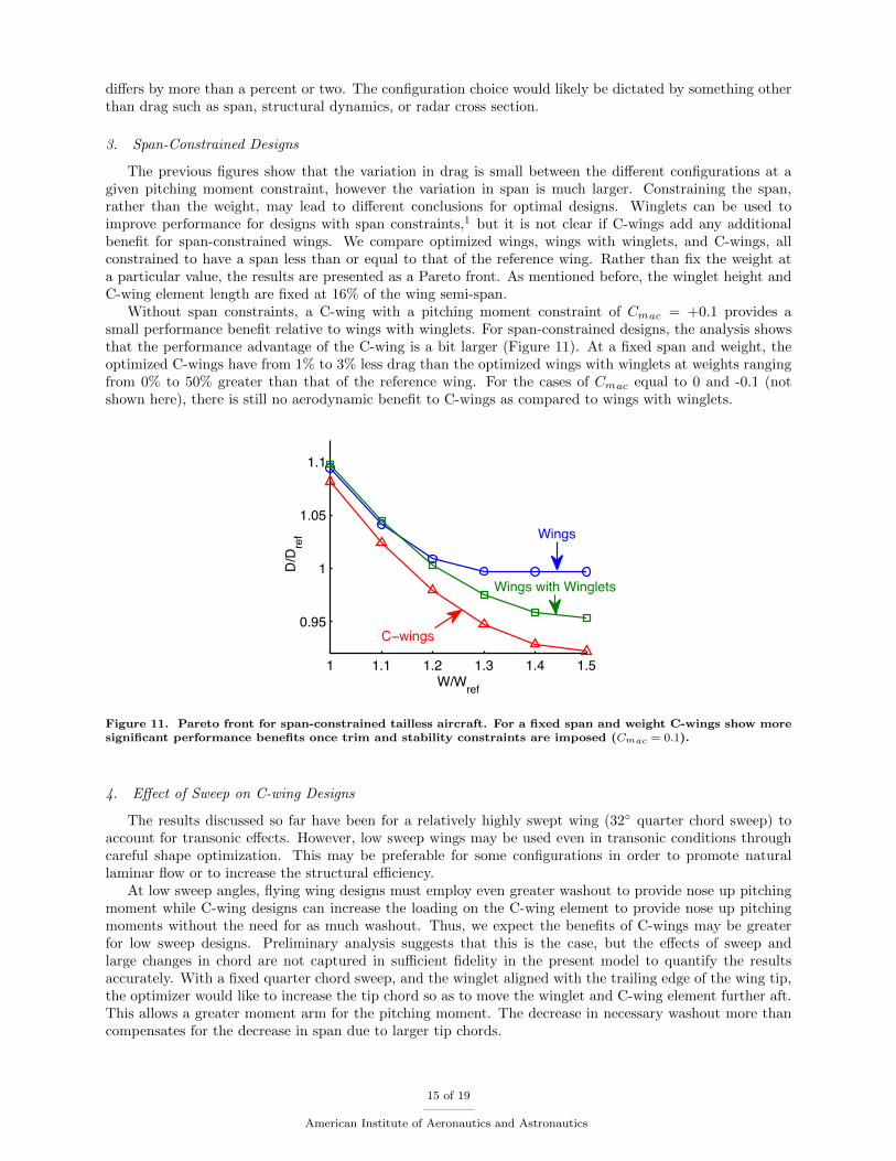
3. Span-Constrained Designs
The previous figures show that the variation in drag is small between the di↵erent configurations at agiven pitching moment constraint, however the variation in span is much larger. Constraining the span,rather than the weight, may lead to di↵erent conclusions for optimal designs. Winglets can be used toimprove performance for designs with span constraints,1 but it is not clear if C-wings add any additionalbenefit for span-constrained wings. We compare optimized wings, wings with winglets, and C-wings, allconstrained to have a span less than or equal to that of the reference wing. Rather than fix the weight ata particular value, the results are presented as a Pareto front. As mentioned before, the winglet height andC-wing element length are fixed at 16% of the wing semi-span.
Without span constraints, a C-wing with a pitching moment constraint of C
m
ac
= +0.1 provides asmall performance benefit relative to wings with winglets. For span-constrained designs, the analysis showsthat the performance advantage of the C-wing is a bit larger (Figure 11). At a fixed span and weight, theoptimized C-wings have from 1% to 3% less drag than the optimized wings with winglets at weights rangingfrom 0% to 50% greater than that of the reference wing. For the cases of C
m
ac
equal to 0 and -0.1 (notshown here), there is still no aerodynamic benefit to C-wings as compared to wings with winglets.
1 1.1 1.2 1.3 1.4 1.5
0.95
1
1.05
1.1
W/Wref
D/D
ref
Wings
C−wings
Wings with Winglets
Figure 11. Pareto front for span-constrained tailless aircraft. For a fixed span and weight C-wings show moresignificant performance benefits once trim and stability constraints are imposed (C
m
ac
= 0.1).
4. E↵ect of Sweep on C-wing Designs
The results discussed so far have been for a relatively highly swept wing (32� quarter chord sweep) toaccount for transonic e↵ects. However, low sweep wings may be used even in transonic conditions throughcareful shape optimization. This may be preferable for some configurations in order to promote naturallaminar flow or to increase the structural e�ciency.
At low sweep angles, flying wing designs must employ even greater washout to provide nose up pitchingmoment while C-wing designs can increase the loading on the C-wing element to provide nose up pitchingmoments without the need for as much washout. Thus, we expect the benefits of C-wings may be greaterfor low sweep designs. Preliminary analysis suggests that this is the case, but the e↵ects of sweep andlarge changes in chord are not captured in su�cient fidelity in the present model to quantify the resultsaccurately. With a fixed quarter chord sweep, and the winglet aligned with the trailing edge of the wing tip,the optimizer would like to increase the tip chord so as to move the winglet and C-wing element further aft.This allows a greater moment arm for the pitching moment. The decrease in necessary washout more thancompensates for the decrease in span due to larger tip chords.
15 of 19
American Institute of Aeronautics and Astronautics
D. Maneuver Load Alleviation
The same set of tools described here can be used to analyze a much broader range of conceptual wingdesign problems than the tip design cases presented so far. Many wing design problems have the sameimportant objectives and constraints relating to drag, lift, weight, stability and trim, and stall speed. Asone example, the methodology is applied to planar wings designed with active load alleviation.
Many of the previous results have shown how the conditions at the maneuver load a↵ect the optimaldesign. In particular, for a C
L
mvr
/C
L
other than 1, it is clear that the additional lift distribution is tailoredto balance an e�cient cruise load with an inboard loaded maneuver load. If we are also able to change thebasic lift distribution (i.e. dynamically twist the wing), then the di↵erence between an ideal cruise loaddistribution and an ideal structural limit load distribution can be exploited even further. Here, it is assumedthat the aircraft can provide gust load alleviation in a similar manner, but that the structure is critical atmaneuver.
For simplicity, this analysis is for a planar wing with five trapezoidal sections and no tip devices. Thedesign variables include span, chord distribution, and twist distribution. In addition, the twist distribution atthe maneuver load must be included. The cruise load distribution and structural limit load distribution arethen only coupled through the planform geometry, and not through the twist distribution. The objective is tominimize drag at cruise subject to constraints on cruise lift, maneuver lift, maneuver weight, and stall speed.Additionally, the maneuver lift distribution must not stall. Since the wing is planar, the weight calculationcan be simplified by fixing the wetted area so that only load dependent weight need be considered. Theoptimization problem is given as:
min. J =D
D
ref
w.r.t. b, {c}, {✓}, {✓}mvr
s.t. 1� L
L
ref
0
1� L
mvr
2.5 L
ref
0
W
mvr
W
ref
� 1 0
{cl
}|C
L
max
� {cl
max
} 0
{cl
}|C
L
mvr
� {cl
max
} 0
{�mvr
}�
ref
� 0
S
S
ref
� 1 = 0
0.5 <
b
b
ref
< 5
0.01 <
c
c
ref
< 5
�20� < ✓ < 20�
�20� < ✓
mvr
< 20�
Since the twist distribution at maneuver is independent of the twist distribution at cruise, the parameterC
L
mvr
/C
L
is no longer important. Instead the parameter cl
max
/C
L
mvr
governs the design. This parameteris like c
l
max
/C
L
max
, since stall becomes critical at maneuver as well as at CL
max
, and reflects the degree towhich the maneuver lift distribution is constrained by stall. This ratio approaches one (flatter c
l
distribution)as the critical structural altitude is increased, or as the cruise lift coe�cient is increased at fixed altitudes.
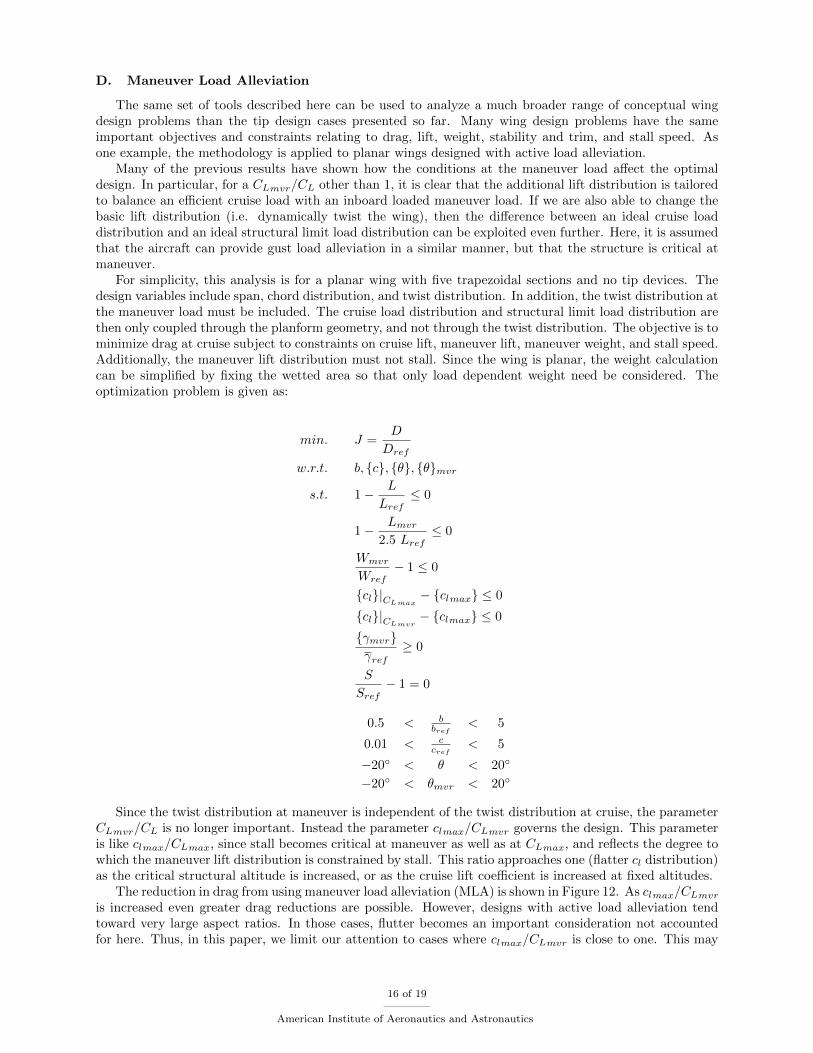
The reduction in drag from using maneuver load alleviation (MLA) is shown in Figure 12. As cl
max
/C
L
mvr
is increased even greater drag reductions are possible. However, designs with active load alleviation tendtoward very large aspect ratios. In those cases, flutter becomes an important consideration not accountedfor here. Thus, in this paper, we limit our attention to cases where c
l
max
/C
L
mvr
is close to one. This may
16 of 19
American Institute of Aeronautics and Astronautics
be excessive for realistic designs, but illustrates the trend. For these cases, using maneuver load alleviationo↵ers about 15-20% drag savings.
1 1.05 1.1 1.15
0.8
0.9
1
1.1
cl max / CL mvr
D/D
ref
without MLA
with MLA
Figure 12. Drag reduction as a function of cl
max
/CL
mvr
(wings constrained not to stall at cruise or maneuverload). MLA shows drag savings on the order of 15-20%.
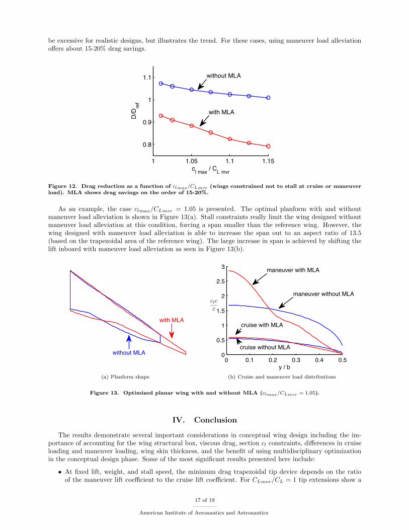
As an example, the case c
l
max
/C
L
mvr
= 1.05 is presented. The optimal planform with and withoutmaneuver load alleviation is shown in Figure 13(a). Stall constraints really limit the wing designed withoutmaneuver load alleviation at this condition, forcing a span smaller than the reference wing. However, thewing designed with maneuver load alleviation is able to increase the span out to an aspect ratio of 13.5(based on the trapezoidal area of the reference wing). The large increase in span is achieved by shifting thelift inboard with maneuver load alleviation as seen in Figure 13(b).
with MLA
without MLA
(a) Planform shape
0 0.1 0.2 0.3 0.4 0.50
0.5
1
1.5
2
2.5
3
y / b
c
l
c
c̄
maneuver without MLA
maneuver with MLA
cruise without MLA
cruise with MLA
(b) Cruise and maneuver load distributions
Figure 13. Optimized planar wing with and without MLA (cl
max
/CL
mvr
= 1.05).
IV. Conclusion
The results demonstrate several important considerations in conceptual wing design including the im-portance of accounting for the wing structural box, viscous drag, section c
l
constraints, di↵erences in cruiseloading and maneuver loading, wing skin thickness, and the benefit of using multidisciplinary optimizationin the conceptual design phase. Some of the most significant results presented here include:
• At fixed lift, weight, and stall speed, the minimum drag trapezoidal tip device depends on the ratioof the maneuver lift coe�cient to the cruise lift coe�cient. For C
L
mvr
/C
L
= 1 tip extensions show a
17 of 19
American Institute of Aeronautics and Astronautics
slight advantage compared with winglets, while for CL
mvr
/C
L
= 2.5 winglets are slightly better thantip extensions. These trends apply both for wing retrofits and for new wing designs.
• C-wings for tailless aircraft have slightly lower drag compared with wings and wings with wingletswhen stability and trim constraints are imposed. This may be especially true for designs with spanconstraints or low sweep.
• Maneuver Load Alleviation (and Gust Load Alleviation) can o↵er significant reductions in drag (onthe order of 15% for the designs evaluated here); however, an analysis of the structural dynamics isnecessary for the resulting high aspect ratio designs.
These conclusions represent fundamental multidisciplinary considerations in wing design. Design deci-sions, however, would need to be made in the context of specific and complete design studies. For example,as pointed out by Heyson et al., it is not clear that an increase in wing weight will lead to an increase in totalaircraft weight. It may be that the increase in wing weight is o↵set by the decrease in fuel weight due to thereduction in drag. Many more complex trade-o↵s exist as entire configurations and missions are optimized.Although this paper is meant to explore results of a more general nature, the methodology can be applied inspecific conceptual design studies as the methods allows for e�cient exploration of large areas of the designspace.
A few extensions to the method are currently being pursued. Transonic drag rise, airfoil section de-sign, variation in material properties (especially in winglets), torsion-dependent weight (may be particularlyimportant for raked tips), and steady aeroelastics are a few areas that may yield additional insights.
Acknowledgments
The authors gratefully acknowledge support from the National Defense Science and Engineering Graduate(NDSEG) Fellowship program.
References
1Kroo, I., “Nonplanar Wing Concepts for Increased Aircraft E�ciency,” VKI Lecture Series on Innovative Configurationsand Advanced Concepts for Future Civil Aircraft , June 2005.
2Hemke, P. E., “Drag of Wings with End Plates,” TR-267, NACA, 1928.3Mangler, W., “The Lift Distribution of Wings with End Plates,” TM-856, NACA, 1938.4Whitcomb, R. T., “A Design Approach and Selected Wind-Tunnel Results At High Subsonic Mounted Speeds for
Winglets,” TN-D-8260, NASA, July 1976.5Heyson, H. H., Riebe, G. D., and Fulton, C. L., “Theoretical Parametric Study of the Relative Advantages of Winglets
and Wing-Tip Extensions,” TP-1020, NASA, September 1977.6Flechner, S. G. and Jacobs, P. F., “Experimental Results of Winglets on First, Second, and Third Generation Jet
Transports,” CTOL Transport Technology, Langley Research Center, Jan. 1978, pp. 553–569.7Jones, R. T. and Lasinski, T. A., “E↵ect of Winglets on the Induced Drag of Ideal Wing Shapes,” TM-81230, NASA,
September 1980.8Kroo, I., “Design and Analysis of Optimally-Loaded Lifting Systems,” AIAA 84-2507 , October 1984.9Asai, K., “Theoretical Considerations in the Aerodynamic E↵ectiveness of Winglets,” Journal of Aircraft , Vol. 22, No. 7,
July 1985, pp. 635–637, doi:10.2514/3.45177.10Zimmer, H., The Aerodynamic Optimization of Wings at Subsonic Speeds and the Influence of Wing Design, Ph.D.
thesis, University of Stuttgart, Stuttgart, Germany, 1983, Translated into English in NASA TM-88534.11Slingerland, R. and Verstraeten, J. G., “Drag Characteristics for Optimally Span-loaded Planar, Wingletted, and C-
wings,” 46th AIAA Aerospace Sciences Meeting and Exhibit , AIAA, January 2008.12Jones, R. T., “The Spanwise Distribution of Lift for Minimum Induced Drag of Wings Having a Given Lift and a Given
Bending Moment,” TN-2249, NACA, December 1950.13McGeer, T., Wing Design for Minimum Drag with Practical Constraints, Ph.D. thesis, Stanford University, Dec. 1983.14Ning, S. A. and Kroo, I., “Tip Extensions, Winglets, and C-wings: Conceptual Design and Optimization,” 26th AIAA
Applied Aerodynamics Conference, AIAA, August 2008.15Weissinger, J., “The Lift Distribution of Swept-Back Wings,” TM-1120, NACA, March 1947, Translation of Uber die
Auftriebsverteilung von Pfeilflugeln Forschungsbericht Nr. 1553.16Federal Aviation Administration, FAR Part 25-337 .17Lowson, M. V., “Minimum Induced Drag for Wings with Spanwise Camber,” Journal of Aircraft , Vol. 27, No. 7, July
1990, pp. 627–631, doi:10.2514/3.56861.18von Karman, T. and Burgers, J. M., Airfoils and Airfoil Systems of Finite Span, Vol. 2 of General Aerodynamic Theory-
Perfect Fluids, Springer (Berlin), 1935.
18 of 19
American Institute of Aeronautics and Astronautics
19McMasters, J. H., Paisley, D. J., Hubert, R. J., Kroo, I., Bofah, K. K., Sullivan, J. P., and Drela, M., “AdvancedConfigurations for Very Large Subsonic Transport Airplanes,” CR-201614, NASA, October 1996.
19 of 19
American Institute of Aeronautics and Astronautics