multi vision 2010td for differential digital transmitter ... · multi vision digital transmitter...
TRANSCRIPT

Multi Vision�
Digital Transmitter
Instructions
2010TD for DifferentialPressure, Flow Rate,and Level
2010TA for Absolute Pressure
42/15-712-7 EN
2 of 28 42/15-712-7 EN for 2010TD / 2010TA 08.2001
Contentspage
1 Safety. . . . . . . . . . . . . . . . . . . . . . . . . . . . . . . . . . . . . . . . . . . . . . 2General safety precautions and health protection . . . . . . . . . 2Correct usage . . . . . . . . . . . . . . . . . . . . . . . . . . . . . . . . . . . . . 2
2 Transport and Storage . . . . . . . . . . . . . . . . . . . . . . . . . . . . 2
3 General Description . . . . . . . . . . . . . . . . . . . . . . . . . . . . . . 3Principle of operation and construction . . . . . . . . . . . . . . . . . . . . 3Documentation . . . . . . . . . . . . . . . . . . . . . . . . . . . . . . . . . . . . 3
4 Mounting . . . . . . . . . . . . . . . . . . . . . . . . . . . . . . . . . . . . . . . 4General . . . . . . . . . . . . . . . . . . . . . . . . . . . . . . . . . . . . . . . . . 4Transmitter . . . . . . . . . . . . . . . . . . . . . . . . . . . . . . . . . . . . . . 4Measurement piping . . . . . . . . . . . . . . . . . . . . . . . . . . . . . . . 4
5 Electrical Connection . . . . . . . . . . . . . . . . . . . . . . . . . . . . . 4Electrical connection in the cable connection compartment . 4Electrical connection with plug . . . . . . . . . . . . . . . . . . . . . . . 4Mounting of the socket connector . . . . . . . . . . . . . . . . . . . . . 4Protective conductor / grounding. . . . . . . . . . . . . . . . . . . . . . 5Set-up of the signal circuit / communication circuit . . . . . . . . 5of transmitters with 4...20 mA-output signalNotes for connecting the cable . . . . . . . . . . . . . . . . . . . . . . . 5Notes on PROFIBUS-PA transmitters . . . . . . . . . . . . . . . . . . . . . 6Notes on explosion protection . . . . . . . . . . . . . . . . . . . . . . . . 6
6 Commissioning . . . . . . . . . . . . . . . . . . . . . . . . . . . . . . . . . . 6Notes of transmitters with 4...20mA-output signal . . . . . . . . . 7Write protection . . . . . . . . . . . . . . . . . . . . . . . . . . . . . . . . . . . 7Sensor misalignment / zero correction . . . . . . . . . . . . . . . . . 7Assembly / disassembly of push button unit . . . . . . . . . . . . . 7Rotate housing with regard to the sensor . . . . . . . . . . . . . . . 7Mount LCD-indicator . . . . . . . . . . . . . . . . . . . . . . . . . . . . . . . 7Secure enclosure cover for EEx d . . . . . . . . . . . . . . . . . . . . . 8
7 Operation . . . . . . . . . . . . . . . . . . . . . . . . . . . . . . . . . . . . . . . 8Operation with “local keys” without LCD-indicator. . . . . . . . . 8Operation with “local keys” with LCD-indicator . . . . . . . . . . . 9Measured value display. . . . . . . . . . . . . . . . . . . . . . . . . . . . 10Program control . . . . . . . . . . . . . . . . . . . . . . . . . . . . . . . . . . 11Operation with PC / Laptop or Hand-held-terminal . . . . . . . 12
8 Maintenance. . . . . . . . . . . . . . . . . . . . . . . . . . . . . . . . . . . . 13Dismantling / fitting the process flanges . . . . . . . . . . . . . . . 13
9 Repairs . . . . . . . . . . . . . . . . . . . . . . . . . . . . . . . . . . . . . . . . 14Return . . . . . . . . . . . . . . . . . . . . . . . . . . . . . . . . . . . . . . . . . 14
10 Technical Data . . . . . . . . . . . . . . . . . . . . . . . . . . . . . . . . . . 14
11 Dimensional Diagrams . . . . . . . . . . . . . . . . . . . . . . . . . . . 18
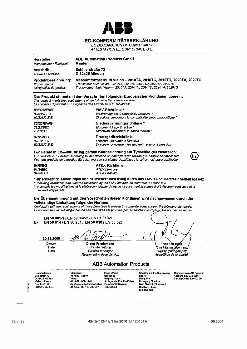
EC Declaration of Conformity . . . . . . . . . . . . . . . . . . . . . 22EC-Type-Examination Certificate (II1/2G EEx ia IIC T6) . 23
1 Safety General safety precautions and health protectionTo ensure safe operation of the 2010TA / 2010TD Transmitters,the following instructions have to be observed:
☞Please read these instructions / operating manual carefullyprior to assembly and commissioning!For reasons of clarity the instructions do not contain all details onall types of product and do therefore not take into account everyconceivable case of assembly, operation or maintenance. If you want further information or if special problems arise whichare not treated in detail in the instructions, please ask the manu-facturer for the necessary information. Moreover we would like to point out that the content of these in-
structions is neither part of nor provided for changing a previous orexisting agreement, promise or legal relationship. All obligations ofABB Automation Products GmbH result from the respective salescontract which also comprises the complete and solely valid war-ranty clauses. Such contractual warranty clauses will neither belimited nor extended by the content of these instructions.
☞Observe warning signs at packaging etc.!
☞For assembly, electrical connection, commissioning andmaintenance of the transmitter, only qualified and authorized spe-cialists are to be employed. Qualified specialists are persons who are experienced in the as-sembly, electrical connection, commissioning and operation of thetransmitter or similar devices holding the necessary qualificationsfor their job, e.g.:● Training or instruction and / or authorization to operate and
maintain devices / systems according to the safety engineeringstandard for electric circuits, high pressures and aggressivemedia.
● Training or instruction according to the safety engineeringstandard regarding maintenance and use of adequate safetysystems.
For the sake of your own safety we draw your attention tothe fact that for the electrical connection, only sufficientlyisolated tools acc. to DIN EN 60 900 may be used.
● Furthermore the pertinent safety regulations concerning theconstruction and operation of electrical installations, e.g. therule regarding technical working material §3 (safety rule for in-struments), have to be observed.
● The pertinent standards, e.g. DIN 31 000 / VDE 1000.
● The regulations and recommendations relating to explosionprotection if explosion-proof transmitters are to be installed.
● The device can be operated with high pressure and aggressivemedia.
Serious injury and / or considerable material damagecan therefore be caused when this device is handled in-correctly.
● The regulations, standards, recommendations and rules men-tioned in these instructions are valid in Germany. When usingthe transmitter in other countries, the pertinent national ruleshave to be observed.
Correct usageThe 2010TD Transmitter measures differential pressure, flow rateor level; the 2010TA Transmitter measures absolute pressure ofgases, vapors and liquids. The measuring ranges are graduatedfrom 10 mbar to 100 bar for the 2010TD resp. from 400 mbar abs.to 20 bar abs. for the 2010TA, each for the nominal pressure stag-es PN 160, PN 250 and PN 400. The transmitter can be overload-ed on one side up to the relevant nominal pressure.
2 Transport and StorageAfter unpacking the transmitter, check the device for transportdamage. Check the packing material for accessories. During intermediate storage / transport, store and transport thetransmitter in the original packaging only. See section 10 "Techni-cal Data" for permissible ambient conditions regarding storage andtransport. The storage time is indefinite, however, the warrantyconditions stipulated in the order confirmation of the supplier arevalid.
08.2001 42/15-712-7 EN for 2010TD / 2010TA 3 of 28
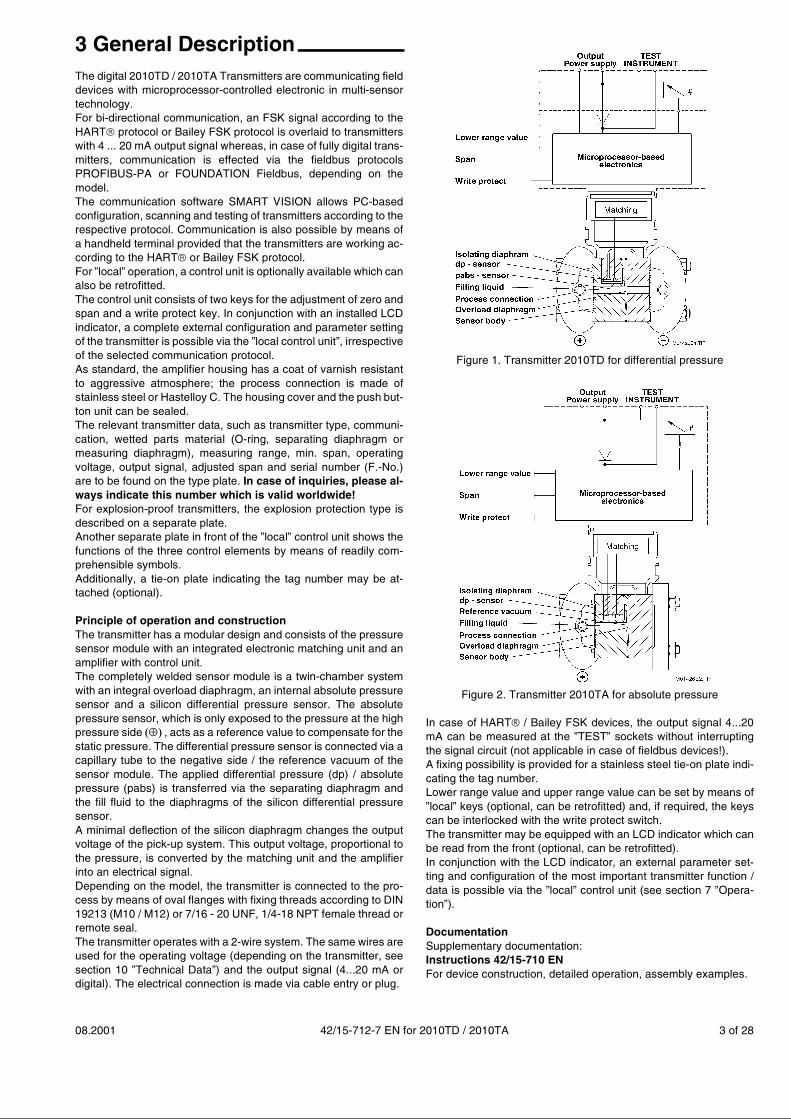
3 General DescriptionThe digital 2010TD / 2010TA Transmitters are communicating fielddevices with microprocessor-controlled electronic in multi-sensortechnology. For bi-directional communication, an FSK signal according to theHART� protocol or Bailey FSK protocol is overlaid to transmitterswith 4 ... 20 mA output signal whereas, in case of fully digital trans-mitters, communication is effected via the fieldbus protocolsPROFIBUS-PA or FOUNDATION Fieldbus, depending on themodel. The communication software SMART VISION allows PC-basedconfiguration, scanning and testing of transmitters according to therespective protocol. Communication is also possible by means ofa handheld terminal provided that the transmitters are working ac-cording to the HART� or Bailey FSK protocol.For ”local” operation, a control unit is optionally available which canalso be retrofitted. The control unit consists of two keys for the adjustment of zero andspan and a write protect key. In conjunction with an installed LCDindicator, a complete external configuration and parameter settingof the transmitter is possible via the ”local control unit”, irrespectiveof the selected communication protocol. As standard, the amplifier housing has a coat of varnish resistantto aggressive atmosphere; the process connection is made ofstainless steel or Hastelloy C. The housing cover and the push but-ton unit can be sealed.The relevant transmitter data, such as transmitter type, communi-cation, wetted parts material (O-ring, separating diaphragm ormeasuring diaphragm), measuring range, min. span, operatingvoltage, output signal, adjusted span and serial number (F.-No.)are to be found on the type plate. In case of inquiries, please al-ways indicate this number which is valid worldwide!For explosion-proof transmitters, the explosion protection type isdescribed on a separate plate. Another separate plate in front of the ”local” control unit shows thefunctions of the three control elements by means of readily com-prehensible symbols.Additionally, a tie-on plate indicating the tag number may be at-tached (optional).
Principle of operation and constructionThe transmitter has a modular design and consists of the pressuresensor module with an integrated electronic matching unit and anamplifier with control unit.The completely welded sensor module is a twin-chamber systemwith an integral overload diaphragm, an internal absolute pressuresensor and a silicon differential pressure sensor. The absolutepressure sensor, which is only exposed to the pressure at the highpressure side ����, acts as a reference value to compensate for thestatic pressure. The differential pressure sensor is connected via acapillary tube to the negative side / the reference vacuum of thesensor module. The applied differential pressure (dp) / absolutepressure (pabs) is transferred via the separating diaphragm andthe fill fluid to the diaphragms of the silicon differential pressuresensor.A minimal deflection of the silicon diaphragm changes the outputvoltage of the pick-up system. This output voltage, proportional tothe pressure, is converted by the matching unit and the amplifierinto an electrical signal.Depending on the model, the transmitter is connected to the pro-cess by means of oval flanges with fixing threads according to DIN19213 (M10 / M12) or 7/16 - 20 UNF, 1/4-18 NPT female thread orremote seal.The transmitter operates with a 2-wire system. The same wires areused for the operating voltage (depending on the transmitter, seesection 10 ”Technical Data”) and the output signal (4...20 mA ordigital). The electrical connection is made via cable entry or plug.
Figure 1. Transmitter 2010TD for differential pressure
Figure 2. Transmitter 2010TA for absolute pressure
In case of HART��/ Bailey FSK devices, the output signal 4...20mA can be measured at the ”TEST” sockets without interruptingthe signal circuit (not applicable in case of fieldbus devices!). A fixing possibility is provided for a stainless steel tie-on plate indi-cating the tag number. Lower range value and upper range value can be set by means of”local” keys (optional, can be retrofitted) and, if required, the keyscan be interlocked with the write protect switch. The transmitter may be equipped with an LCD indicator which canbe read from the front (optional, can be retrofitted). In conjunction with the LCD indicator, an external parameter set-ting and configuration of the most important transmitter function /data is possible via the ”local” control unit (see section 7 ”Opera-tion”).
DocumentationSupplementary documentation:Instructions 42/15-710 ENFor device construction, detailed operation, assembly examples.

4 of 28 42/15-712-7 EN for 2010TD / 2010TA 08.2001
4 Mounting GeneralBefore mounting the transmitter, check whether the model meetsthe measurement and safety requirements of the measuring point,e.g. with regard to materials, pressure rating, temperature, explo-sion protection and operating voltage. The relevant recommenda-tions, regulations, standards and the rules for prevention of acci-dents must also be observed! (e.g. VDE / VDI 3512, DIN 19210,VBG, Elex V, etc.)Measurement accuracy is largely dependent upon correct installa-tion of the transmitter and the related measurement piping(s). Themeasuring set-up should be screened as much as possible fromcritical ambient conditions such as major temperature variations,vibration and shock. If unfavorable ambient conditions cannot beavoided owing to reasons related to building structure, measuringrequirements or other reasons, this may influence the measure-ment quality! (see section 10 ”Technical Data”). If remote seals with capillary tubes are attached to the transmitter,see also the Instructions 42/15-813 EN.
TransmitterThe transmitter can be connected directly onto the shut-off valve.There is also a mounting bracket for wall or pipe mounting (2” pipe)available as an accessory.Preferably in such a position that the process flange axes are ver-tical (horizontal with barrel-type amplifier housing) so as to avoidzero shifts.If the transmitter were installed inclined, the hydrostatic pressureof the filling fluid would exert pressure on the sensing dia-phragmand thus cause a zero shift! A zero point correction would then benecessary.Various versions are available for connecting the measuring lines,and these are shown in detail on the dimensional diagram. Uncon-nected process connections on the measuring mechanism mustbe sealed with the enclosed blanking plugs (1/4-18 NPT).For this purpose use your officially approved sealant.Please refer to section 11 ”Dimensional Diagrams” for possi-ble mounting with bracket.
Measuring pipingThe following points must be observed for correct installation:• Keep the measurement piping as short as possible and avoid sharp
bends.
• Lay the measurement pipings so that no deposits can accumulate.Gradients should not be less than 8 %.
• Measurement pipings should be blown through with compressed airor, better still, flushed through with the measuring medium beforeconnecting to the measuring element.
• If the medium is a liquid/vapour the filling liquid must be at the samelevel in both pipes. If using separating liquids, both pipes must befilled to the same height (2010TD).
• Keep both pipes at the same temperature whenever possible(2010TD).
• Completely bleed measuring pipings if the medium is a liquid.
• Lay the process piping so that gas bubbles, when measuring liquids,or condensate when measuring gases, can flow back into the proc-ess piping.
• Ensure that the process piping is correctly connected (+ HP and – LPside on measuring mechanism, seals, ...).
• Take care of the tightness of the connection.
• Lay the process piping so that blow-outs do not occur via the trans-mitter!
5 Electrical connectionThe relevant guidelines must be observed during the electri-cal installation!Since the transmitter has no switch-off elements, overcurrentprotection devices or mains disconnection possibilities mustbe provided on the system side. (Overvoltage protection atoption)Check that the existing operating voltage corresponds to that indi-cated on the type plate. For power supply and output signal, thesame lines are used. Consult the enclosed connection dia-gram! Depending on the supplied model, the electrical connectionis made via cable entry 1/2-14 NPT or M 20 x 1.5 or via plug Han8 U. The screw terminals are suitable for wire cross-sections up to2.5 mm2.Caution: For transmitters of category 3 regarding the applicationin "Zone 2" the cable gland has to be provided by the customer. Forthis purpose there is a thread of size M 20 x 1.5 in the electronichousing. The cable gland must comply with the protection type "In-creased Safety EEx e" according to the directions 94/9/EG (AT-EX). Furthermore, the conditions stated in the type test certificateof the cable gland have to be observed!Note: If the type of protection ”Flameproof enclosure” (EEx d) ap-plies to the transmitter, the enclosure cover has to be locked bymeans of the attachment screw (Fig. 9).We would like to point out here that after intervals of several weeksan increased force is required to screw off the housing. This effectis not caused by the thread but only due to the gasket type.
Electrical connection in the cable connection compartment
Figure 3. Cable connection compartmentElectrical connection with plug
„barrel-type“ „DIN-type“Figure 4. Plug connection
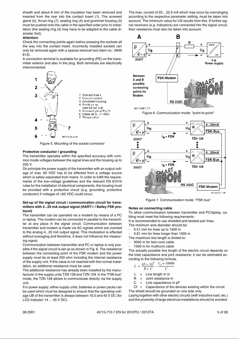
Mounting of the socket connectorThe socket connector for the cable connection is enclosed with thetransmitter for the plug version. Installation (see Fig. 5):The contact sockets (2) are crimped or soldered onto the cableends (wire cross-section 0.75...1 mm²) from which 1.5...2 cm of the
08.2001 42/15-712-7 EN for 2010TD / 2010TA 5 of 28
sheath and about 8 mm of the insulation has been removed andinserted from the rear into the contact insert (1). The screwedgland (5), thrust ring (7), sealing ring (4) and grommet housing (3)must be pushed onto the cable in the specified order prior to instal-lation (the sealing ring (4) may have to be adapted to the cable di-ameter first). Attention:Check the connecting points again before pressing the sockets allthe way into the contact insert. Incorrectly installed sockets canonly be removed again with a special removal tool (item no.: 0949813). A connection terminal is available for grounding (PE) on the trans-mitter exterior and also in the plug. Both terminals are electricallyinterconnected.
Figure 5. Mounting of the socket connector
Protective conductor / groundingThe transmitter operates within the specified accuracy with com-mon mode voltages between the signal lines and the housing up to250 V.On principle the power supply of the transmitter with an output volt-age of max. 60 VDC has to be effected from a voltage sourcewhich is safely separated from mains. In order to fulfill the require-ments of the low-voltage guidelines and the relevant EN 61010rules for the installation of electrical components, the housing mustbe provided with a protective circuit (e.g. grounding, protectiveconductor) if voltages of >60 VDC could occur.
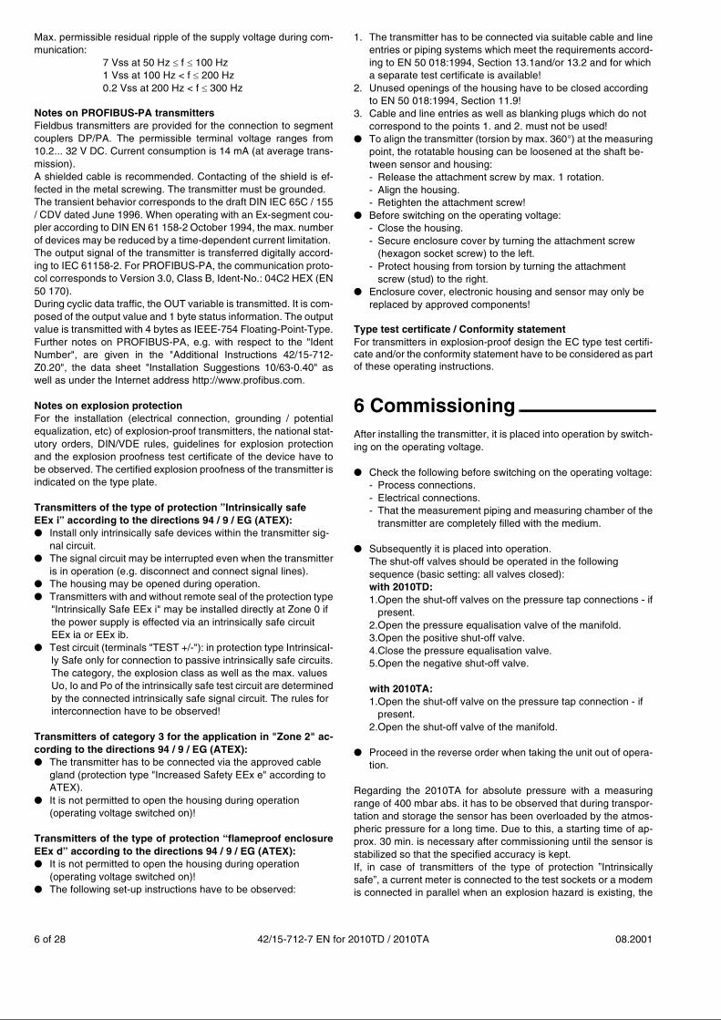
Set-up of the signal circuit / communication circuit for trans-mitters with 4...20 mA output signal (HART��/ Bailey FSK pro-tocol)The transmitter can be operated via a modem by means of a PCor laptop. The modem can be connected in parallel to the transmit-ter at any place in the signal circuit. Communication betweentransmitter and modem is made via AC signals which are overlaidto the analog 4...20 mA output signal. This modulation is effectedwithout averaging and therefore, it does not influence the measur-ing signal.Communication between transmitter and PC or laptop is only pos-sible if the signal circuit is set up as shown in Fig. 6. The resistancebetween the connecting point of the FSK modem and the powersupply must be at least 250 ohm including the internal resistanceof the supply unit. If this value is not reached with the normal instal-lation, an additional resistance must be used. The additional resistance has already been installed by the manu-facturer in the supply units TZN 128 and TZN 129. In the ”FSK bus”mode, the TZN 128 allows to communicate directly via the supplyunit. For power supply, either supply units, batteries or power packs canbe used which must be designed to ensure that the operating volt-age UB of the transmitter is always between 10.5 and 45 V DC (forLCD indicator 14 ... 45 V DC).
The max. current of 20... 22.5 mA which may occur by overrangingaccording to the respective parameter setting, must be taken intoaccount. The minimum value for US results from this. If further sig-nal receivers (e.g. indicators) are connected into the signal circuit,their resistance must also be taken into account.
Figure 6. Communication mode: "point-to-point"
Figure 7. Communication mode: "FSK bus"
Notes on connecting cableTo allow communication between transmitter and PC/laptop, ca-bling must meet the following requirements: It is recommended to use shielded and twisted pair lines.The minimum wire diameter should be: - 0.51 mm for lines up to 1500 m- 0.81 mm for lines longer than 1500 m The maximum line length is limited to: - 3000 m for twin-core cable- 1500 m for multicore cableThe actually possible line length of the electric circuit depends onthe total capacitance and joint resistance; it can be estimated ac-cording to the following formula:
L = Line length in mR = Joint resistance in C = Line capacitance in pFCf = Capacitance of the devices existing within the circuit
The shield should be grounded on one side only.Laying together with other electric circuits (with inductive load, etc.)and the proximity of large electrical installations should be avoided.
L 65 106�
R C�--------------------
Cf 10000+
C--------------------------–=
6 of 28 42/15-712-7 EN for 2010TD / 2010TA 08.2001
Max. permissible residual ripple of the supply voltage during com-munication:
7 Vss at 50 Hz � f � 100 Hz 1 Vss at 100 Hz < f � 200 Hz 0.2 Vss at 200 Hz < f � 300 Hz
Notes on PROFIBUS-PA transmittersFieldbus transmitters are provided for the connection to segmentcouplers DP/PA. The permissible terminal voltage ranges from10.2... 32 V DC. Current consumption is 14 mA (at average trans-mission).A shielded cable is recommended. Contacting of the shield is ef-fected in the metal screwing. The transmitter must be grounded.The transient behavior corresponds to the draft DIN IEC 65C / 155/ CDV dated June 1996. When operating with an Ex-segment cou-pler according to DIN EN 61 158-2 October 1994, the max. numberof devices may be reduced by a time-dependent current limitation. The output signal of the transmitter is transferred digitally accord-ing to IEC 61158-2. For PROFIBUS-PA, the communication proto-col corresponds to Version 3.0, Class B, Ident-No.: 04C2 HEX (EN50 170).During cyclic data traffic, the OUT variable is transmitted. It is com-posed of the output value and 1 byte status information. The outputvalue is transmitted with 4 bytes as IEEE-754 Floating-Point-Type.Further notes on PROFIBUS-PA, e.g. with respect to the "IdentNumber", are given in the "Additional Instructions 42/15-712-Z0.20", the data sheet "Installation Suggestions 10/63-0.40" aswell as under the Internet address http://www.profibus.com.
Notes on explosion protectionFor the installation (electrical connection, grounding / potentialequalization, etc) of explosion-proof transmitters, the national stat-utory orders, DIN/VDE rules, guidelines for explosion protectionand the explosion proofness test certificate of the device have tobe observed. The certified explosion proofness of the transmitter isindicated on the type plate.
Transmitters of the type of protection ”Intrinsically safeEEx i” according to the directions 94 / 9 / EG (ATEX):● Install only intrinsically safe devices within the transmitter sig-
nal circuit.● The signal circuit may be interrupted even when the transmitter
is in operation (e.g. disconnect and connect signal lines).● The housing may be opened during operation.● Transmitters with and without remote seal of the protection type
"Intrinsically Safe EEx i" may be installed directly at Zone 0 ifthe power supply is effected via an intrinsically safe circuitEEx ia or EEx ib.
● Test circuit (terminals "TEST +/-"): in protection type Intrinsical-ly Safe only for connection to passive intrinsically safe circuits.The category, the explosion class as well as the max. valuesUo, Io and Po of the intrinsically safe test circuit are determinedby the connected intrinsically safe signal circuit. The rules forinterconnection have to be observed!
Transmitters of category 3 for the application in "Zone 2" ac-cording to the directions 94 / 9 / EG (ATEX):● The transmitter has to be connected via the approved cable
gland (protection type "Increased Safety EEx e" according toATEX).
● It is not permitted to open the housing during operation (operating voltage switched on)!
Transmitters of the type of protection “flameproof enclosureEEx d” according to the directions 94 / 9 / EG (ATEX):● It is not permitted to open the housing during operation
(operating voltage switched on)!● The following set-up instructions have to be observed:
1. The transmitter has to be connected via suitable cable and lineentries or piping systems which meet the requirements accord-ing to EN 50 018:1994, Section 13.1and/or 13.2 and for whicha separate test certificate is available!
2. Unused openings of the housing have to be closed accordingto EN 50 018:1994, Section 11.9!
3. Cable and line entries as well as blanking plugs which do notcorrespond to the points 1. and 2. must not be used!
● To align the transmitter (torsion by max. 360°) at the measuringpoint, the rotatable housing can be loosened at the shaft be-tween sensor and housing: - Release the attachment screw by max. 1 rotation. - Align the housing.- Retighten the attachment screw!
● Before switching on the operating voltage:- Close the housing.- Secure enclosure cover by turning the attachment screw
(hexagon socket screw) to the left.- Protect housing from torsion by turning the attachment
screw (stud) to the right. ● Enclosure cover, electronic housing and sensor may only be
replaced by approved components!
Type test certificate / Conformity statementFor transmitters in explosion-proof design the EC type test certifi-cate and/or the conformity statement have to be considered as partof these operating instructions.
6 CommissioningAfter installing the transmitter, it is placed into operation by switch-ing on the operating voltage.
● Check the following before switching on the operating voltage:- Process connections.- Electrical connections.- That the measurement piping and measuring chamber of the
transmitter are completely filled with the medium.
● Subsequently it is placed into operation.The shut-off valves should be operated in the following sequence (basic setting: all valves closed):with 2010TD:1.Open the shut-off valves on the pressure tap connections - if
present.2.Open the pressure equalisation valve of the manifold.3.Open the positive shut-off valve.4.Close the pressure equalisation valve.5.Open the negative shut-off valve.
with 2010TA:1.Open the shut-off valve on the pressure tap connection - if
present.2.Open the shut-off valve of the manifold.
● Proceed in the reverse order when taking the unit out of opera-tion.
Regarding the 2010TA for absolute pressure with a measuringrange of 400 mbar abs. it has to be observed that during transpor-tation and storage the sensor has been overloaded by the atmos-pheric pressure for a long time. Due to this, a starting time of ap-prox. 30 min. is necessary after commissioning until the sensor isstabilized so that the specified accuracy is kept.If, in case of transmitters of the type of protection ”Intrinsicallysafe”, a current meter is connected to the test sockets or a modemis connected in parallel when an explosion hazard is existing, the
08.2001 42/15-712-7 EN for 2010TD / 2010TA 7 of 28
sums of the capacitance and inductance of all circuits includingtransmitter (see type plate) must be equal to or smaller than thepermissible capacitance and inductance of the intrinsically safesignal circuit (see type plate of the supply unit). Only passive or ex-plosion-proof test devices or indicators may be connected. If the output signal is slow to stabilize, a high damping time con-stant has probably been set in the transmitter.
Notes on transmitters with 4...20 mA output signal(HART��/ Bailey FSK protocol)If the applied pressure is within the values indicated on the typeplate, the output current ranges between 4 and 20 mA. If the ap-plied pressure exceeds the calibrated range, the output current isbetween 3.5 mA and 4 mA in case of underranging or between 20mA and 22.5 mA (according to the respective parameter setting) incase of overranging; standard setting: 3.8 mA / 20.5 mA.In order to prevent errors in the lower flow ranges (2010TD) it ispossible, via the communication tool SMART VISION, to adjust the"Zero suppressor" and/or the lin./sq. rt. transition point. Should novalues have been given then the factory set values will be: 5% forthe lin./sq. rt. transition point and 6% for the "Zero suppressor" ofthe maximum flow, i.e. the 2010TD operates only with the "Zerosuppressor".A current of < 4 mA or > 20 mA may also indicate that the micro-processor has detected an internal error; standard setting: 21 mA.Via the communication tool SMART VISION, an exact diagnosis ofthe error can be performed. A short-time interruption of power sup-ply results in an initialization of the electronic (restart of the pro-gram).
Write protectionWrite protection prevents an illegal overwriting of the configurationdata. If write protection is activated, the function of the keys 0 %and 100 % is disabled. However, it is still possible to read out theconfiguration data by means of SMART VISION (or another com-parable communication tool). If necessary, the control unit can be leaded. Write protection is activated as follows (see also symbolism on theplate):1. First, fully press down the switch with an appropriate screw
driver.2. Then turn the switch clockwise by 90 °�.For deactivation the switch has to be pushed down a little andturned counterclockwise by 90 °�.
Sensor misalignment / zero correctionDuring the installation of the transmitter, zero shifts (e.g. slightly in-clined installed position, uneven liquid columns in the differentialpressure lines, additional remote seals etc.) caused by mountingmay occur which have to be corrected. Note: The transmitter must have reached its operating tempera-ture (approx. 5 min after switch-on if the transmitter has already as-sumed ambient temperature) in order to be able to carry out thezero check. The correction has to be made at dp = 0 / pabs = 0 ! There are two possibilities (point 1A or 1B) to perform the 4...20mA-output signal correction directly at the transmitter (controlunit is available):1A. Apply pressure at lower range value (4 mA) – from the process
or from a pressure pick-off. The pressure must be stable andapplied with high accuracy << 0.05% (observe adjusted dam-ping). Press the 0 % key at the transmitter – output signal is ad-justed to 4 mA. The span remains unchanged.Subsequent to the last actuation of the 0% key, the non-volatilestoring of the lower range value adjusted in this way is effectedafter < 25s for HART and/or
< 110s for PROFIBUS-PA and/or< 15s for FOUNDATION Fieldbus
1B.In conjunction with an installed LCD indicator, call up the menu
item ”SHIFTZERO” via the keys ”M” and ”+”. Corrections aremade by pressing the key ”M” (see also section 7 ”Operation”).
2. Subsequently put the transmitter into the operating state.The above procedure acc. to “1A” has no influence on the displayof the physical differential pressure, but instead corrects the ana-logue output signal. Therefore, a difference may occur betweenthe analogue output signal and the display of the physical differen-tial pressure on the digital display or the SMART VISION commu-nication tool. In order to avoid this difference, the necessary zero-point shift must be carried out using the SMART VISION (menupath Configure_Differential Pressure Measurement_ProcessVariable (Oblique Sensor)).However, then a zero-point shift must not have been carriedout with the 0% key beforehand.
Rotate housing with regard to the sensor The electronic housing can be rotated through 360°� and can befixed in any position. A stop prevents the housing from beingturned too far. To this effect, the fixing screw at the housing shaft (hexagon sock-et screw SW 2.5mm, see section 11 ”Dimensional Diagrams”)must be released and hand-tightened after the position has beenreached.
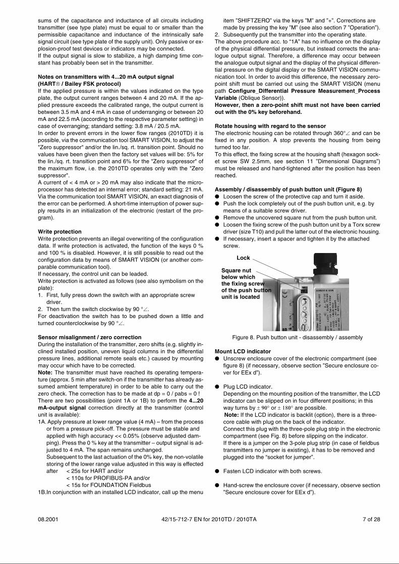
Assembly / disassembly of push button unit (Figure 8)● Loosen the screw of the protective cap and turn it aside.● Push the lock completely out of the push button unit, e.g. by
means of a suitable screw driver.● Remove the uncovered square nut from the push button unit.● Loosen the fixing screw of the push button unit by a Torx screw
driver (size T10) and pull the latter out of the electronic housing.● If necessary, insert a spacer and tighten it by the attached
screw.
Figure 8. Push button unit - disassembly / assembly
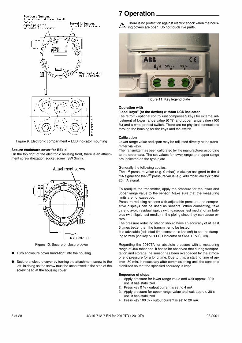
Mount LCD indicator● Unscrew enclosure cover of the electronic compartment (see
figure 8) (if necessary, observe section ”Secure enclosure co-ver for EEx d”).
● Plug LCD indicator.Depending on the mounting position of the transmitter, the LCDindicator can be slipped on in four different positions; in thisway turns by ����� or ���� are possible.Note: If the LCD indicator is backlit (option), there is a three-core cable with plug on the back of the indicator.Connect this plug with the three-pole plug strip in the electroniccompartment (see Fig. 8) before slipping on the indicator.If there is a jumper on the 3-pole plug strip (in case of fieldbustransmitters no jumper is existing), it has to be removed andplugged into the “socket for jumper”.
● Fasten LCD indicator with both screws.
● Hand-screw the enclosure cover (if necessary, observe section”Secure enclosure cover for EEx d”).
Lock
Square nutbelow whichthe fixing screwof the push buttonunit is located
8 of 28 42/15-712-7 EN for 2010TD / 2010TA 08.2001
Figure 9. Electronic compartment – LCD indicator mounting
Secure enclosure cover for EEx dOn the top right of the electronic housing front, there is an attach-ment screw (hexagon socket screw, SW 3mm).
Figure 10. Secure enclosure cover
● Turn enclosure cover hand-tight into the housing.
● Secure enclosure cover by turning the attachment screw to theleft. In doing so the screw must be unscrewed to the stop of thescrew head at the housing cover.
7 Operation There is no protection against electric shock when the hous-ing covers are open. Do not touch live parts.
Figure 11. Key legend plate
Operation with”local keys” (at the device) without LCD indicatorThe retrofit / optional control unit comprises 2 keys for external ad-justment of lower range value (0 %) and upper range value (100%) and a write protect switch. There are no physical connectionsthrough the housing for the keys and the switch.
CalibrationLower range value and span may be adjusted directly at the trans-mitter via keys. The transmitter has been calibrated by the manufacturer accordingto the order data. The set values for lower range and upper rangeare indicated on the type plate.
Generally the following applies:The 1st pressure value (e.g. 0 mbar) is always assigned to the 4mA signal and the 2nd pressure value (e.g. 400 mbar) always to the20 mA signal.
To readjust the transmitter, apply the pressure for the lower andupper range value to the sensor. Make sure that the measuringlimits are not exceeded. Pressure reducing stations with adjustable pressure and compar-ative displays can be used as sensors. When connecting, takecare to avoid residual liquids (with gaseous test media) or air bub-bles (with liquid test media) in the piping since they can cause er-rors. The pressure reducing station should have an accuracy of at least3 times better than the transmitter to be tested. It is advisable (adjusted time constant is known!) to set the damp-ing to zero (via key plus LCD indicator or SMART VISION).
Regarding the 2010TA for absolute pressure with a measuringrange of 400 mbar abs. it has to be observed that during transpor-tation and storage the sensor has been overloaded by the atmos-pheric pressure for a long time. Due to this, a starting time of ap-prox. 30 min. is necessary after commissioning until the sensor isstabilized so that the specified accuracy is kept.
Sequence of steps:1. Apply pressure for lower range value and wait approx. 30 s
until it has stabilized.2. Press key 0 % - output current is set to 4 mA.3. Apply pressure for upper range value and wait approx. 30 s
until it has stabilized.4. Press key 100 % - output current is set to 20 mA.
08.2001 42/15-712-7 EN for 2010TD / 2010TA 9 of 28
5. If necessary, reset damping to the initial value.6. Document new settings.10 s after the last actuation of the 0 % or 100 % keys, the respec-tive parameter is stored in a failsafe way. This procedure of adjustment only changes the 4...20 mA currentsignal. The representation of the physical process pressure on thedigital display or by means of a communication tool, e.g. SMARTVISION, is not changed. To avoid this difference, a correction canbe made via the communication tool SMART VISION and its menupath Calibrate_Differential Pressure Measurement_Adjust In-put.After such a correction, the calibration of the device must bechecked.
Operation with ”local keys” (at the device) with LCD indicatorIn conjunction with an LCD indicator, the transmitter can be config-ured with the keys ( - / + / M) as follows:(Note: Indications in ( ) designate the menu item, they are shownin the 1st and 2nd line of the indicator.)• Exit the menu (EXIT)
• View selected measured and calculated values (VIEW)
• Lower range value with applied pressure (GET 0%)
• Upper range value with applied pressure (GET 100%)
• Lower range value without applied pressure (SET 0%)
• Upper range value without applied pressure (SET 100%)
• Correct zero drift (e.g. oblique sensor) (SHIFTZERO)
• Parallel shift (OFFSET SHIFT)
• Scaling output variable – initial value (OUT 0%)
• Scaling output variable – final value (OUT 100%)
• Damping (DAMPING)
• Output current in case of an error (ALARM CURRENT); onlyavailable for 4...20 mA devices with HART� or Bailey FSK pro-tocol
• Displayed value (DISPLAY)
• Pressure unit (UNIT)
• Temperature unit (UNIT) of internal temperature sensor
• Characteristic (FUNCTION) and the
• Fieldbus address (ADDRESS); only available for devices withPROFIBUS-PA or FOUNDATION Fieldbus protocol.
In the following, some of the a.m. menu items are described in de-tail.
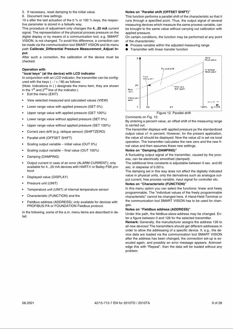
Notes on ”Parallel shift (OFFSET SHIFT)”This function performs a parallel shift of the characteristic so that itruns through a specified point. Thus, the output signal of severalmeasuring devices which measure the same process variable, canbe brought to the same value without carrying out calibration withapplied pressure. On certain conditions, the function may be performed at any pointof the characteristic:● Process variable within the adjusted measuring range● Transmitter with linear transfer function
Figure 12. Parallel shiftComments on Fig. 12:By entering a percent value, an offset shift of the measuring rangeis carried out. The transmitter displays with applied pressure px the standardizedoutput value x1 in percent. However, for the present application,the value x2 should be displayed. Now the value x2 is set via localoperation. The transmitter calculates the new zero and the new fi-nal value and then assumes these new settings. Notes on “Damping (DAMPING)”A fluctuating output signal of the transmitter, caused by the proc-ess, can be electrically smoothed (damped).The additional time constants is adjustable between 0 sec. and 60sec. in stepwise of 0.001s.The damping set in this way does not affect the digitally indicatedvalue in physical units, only the derivatives such as analogue out-put current, free process variable, input signal for controller etc.Notes on “Characteristic (FUNCTION)”In this menu option you can select the functions: linear and freelyprogrammable. The “individuel values of the freely programmablecharacteristic” cannot be changed here. A Hand-Held-Terminal orthe communication tool SMART VISION has to be used for chan-ges.Notes on “Fieldbus address (ADDRESS)”Under this path, the fieldbus-slave-address may be changed. En-ter a figure between 0 and 126 for the selected transmitter. Remark: Generally, the manufacturer assigns the address 126 toall new devices! The transmitters should get different addresses inorder to allow the addressing of a specific device. If, e.g., the de-vice data are loaded via the communication tool SMART VISIONafter the address has been changed, the connection set-up is ex-ecuted again, and possibly an error message appears. Acknowl-edge this with ”Repeat”, then the data will be loaded without anyproblem.

10 of 28 42/15-712-7 EN for 2010TD / 2010TA 08.2001
Measured value display● The LCD indicator2-line, 7-character, 19-segment alphanumeric display with addi-tional bar chart display. Optionally the indicator is available withback illumination.
Figure 13. LCD indicator (optional)
● Display of the physical valueAt the first position of the first line, the sign is displayed. The followingsix positions show the amount of the measured value. The comma isplaced in such a way that the maximum value can be displayed withthese six positions. Die place of the comma is not changed. A commaat the sixth position is not displayed. Thus it is possible to display max.+/-999999. If this value is exceeded�Overflow . is indicated. In thesecond line, the unit is displayed with the last five positions. The first position shows the following characters, if necessary, oneafter the other. Display changes every second.
Table 1: Legend
Figure 14. Control elements (optional)
Display of the percent value
Table 2: Percent value display on LCD indicator
Display for Character Comment
Transfer function �, m or / Always one of thesecharacters appears.
Write protection s Only if write protection hasbeen set.
Cycliccommunication
¸ Only in case ofPROFIBUS-PA
Status available(e.g.measuring rangeinfringement or hard-ware error)
¦ Only if a status is available.
Code ofdisplayed value
1...9 See menu Display(see structure tree)
Transmitter isbusy
Ë This character overwritesother characters.
Characters for:- Transfer function, e.g. linear;- Mode;- Status
Bar chart to display thepercent value
Unit (2nd line)
Current measured value(1st line)
Display on LCD indicator
1st line Percent value, limits: -25% to 125%,2 decimal places
2nd line 1st position: Transfer function (Table 1)2nd position: Write protection (Table 1)7th position: %
Bar chart 2% steps - from -2% to +10%,no hysteresis
Mode key (M)
Keys (+) / (–)
Protecting flat
08.2001 42/15-712-7 EN for 2010TD / 2010TA 11 of 28
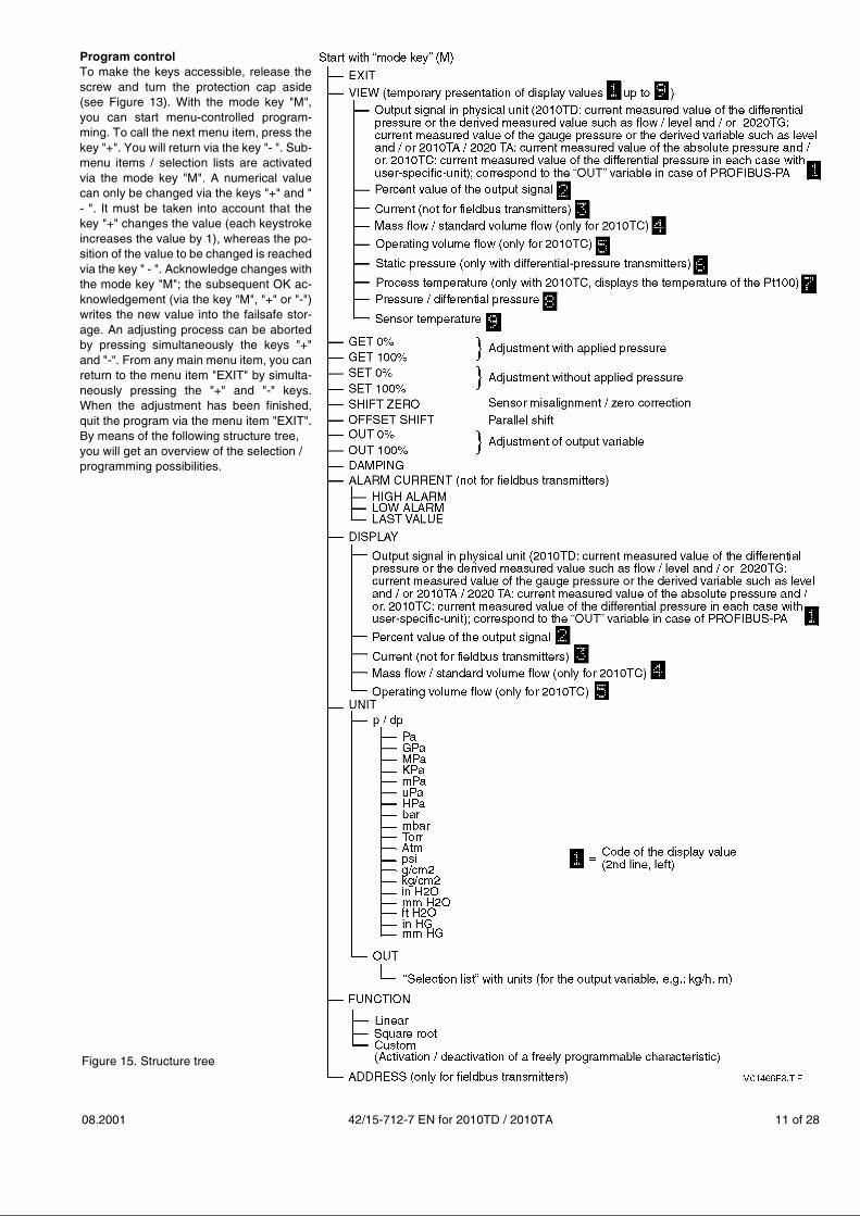
Figure 15. Structure tree
Program controlTo make the keys accessible, release thescrew and turn the protection cap aside(see Figure 13). With the mode key "M",you can start menu-controlled program-ming. To call the next menu item, press thekey "+". You will return via the key "- ". Sub-menu items / selection lists are activatedvia the mode key "M". A numerical valuecan only be changed via the keys "+" and "- ". It must be taken into account that thekey "+" changes the value (each keystrokeincreases the value by 1), whereas the po-sition of the value to be changed is reachedvia the key " - ". Acknowledge changes withthe mode key "M"; the subsequent OK ac-knowledgement (via the key "M", "+" or "-")writes the new value into the failsafe stor-age. An adjusting process can be abortedby pressing simultaneously the keys "+"and "-". From any main menu item, you canreturn to the menu item "EXIT" by simulta-neously pressing the "+" and "-" keys.When the adjustment has been finished,quit the program via the menu item "EXIT".By means of the following structure tree, you will get an overview of the selection / programming possibilities.
12 of 28 42/15-712-7 EN for 2010TD / 2010TA 08.2001
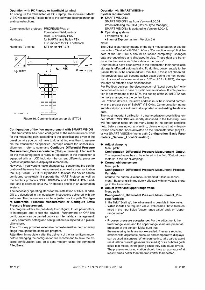
Operation with PC / laptop or handheld terminalTo configure the transmitter via PC / laptop, the software SMARTVISION is required. Please refer to the software description for op-erating instructions.
Communication protocol: PROFIBUS-PA� orFoundation Fieldbus��orHART� or Bailey FSK
Hardware: for HART� and Bailey FSK:FSK modem for PC / notebook
Handheld Terminal: STT 04 or HHT 275
Figure 16. Communication set-up via STT04
Configuration of the flow measurement with SMART VISIONIf the transmitter has been configured at the manufacturer's workfor the measuring point according to the specifications given in thequestionnaire you do not have to do anything else than to assem-ble the transmitter as specified (perhaps correct the sensor mis-alignment - refer to command Configure_Differential PressureMeasurement_Process Variable (Oblique Sensor)). After switchon the measuring point is ready for operation. If the transmitter isequipped with an LCD indicator, the current differential pressure(default adjustment) is displayed immediately.However, it you want to make changes e.g. concerning the config-uration of the mass flow measurement, you need a communicationtool, e.g. SMART VISION. By means of this tool the device can beconfigured completely. It supports the HART Protocol as well asthe fieldbus protocols "PROFIBUS-PA and FOUNDATION Field-bus" and is operable on a PC / Notebook and/or in an automationsystem.The necessary operating steps for the installation of SMART VISI-ON are described in the installation instructions delivered with thesoftware. The parameters can be adjusted via the path Configu-re_Differential Pressure Measurement or Configure_StaticPressure Measurement.The program offers the possibility to configure, to set parameters,to interrogate and to test the devices. Furthermore an OFF-lineconfiguration can be carried out via an internal data management.Every parameter setting and configuration is subjected to a plausi-bility check.The <F1> key provides extensive context-sensitive help at everystage throughout the complete program.Attention: Immediately after the delivery of the transmitters and/orbefore changing the configuration we recommend to save the ex-isting configuration data on a data medium using the commandFile_Save.
Operation via SMART VISION�
System requirements● SMART VISION�
SMART VISION� as from Version 4.00.31When installing the DTM (Device Type Manager), SMART VISION� is updated to Version 4.00.43.
● Operating systems��Windows NT 4.0��Internet Explorer as from Version 5.0
Note:The DTM is started by means of the right mouse button or via themenu item "Device" with "Edit". After a "Connection setup", first thedata of the 2010TD/TA should be loaded completely. Changeddata are underlined and displayed in blue. These data are trans-mitted to the device via "Store data in the device".After the data have been saved in the transmitter, their nonvolatilestorage is effected automatically. To do this, power supply to thetransmitter must be continued for 2 minutes. If this is not observed,the previous data will become active again during the next opera-tion. In case of software versions < 0.20 (< 20 for HART), storagewill only be effected after disconnection.For Profibus devices, the disconnection of "Local operation" onlybecomes effective in case of cyclic communication. If write protec-tion is set by means of the DTM, the setting of the 2010TD/TA canno more changed via the control keys.For Profibus devices, the slave address must be indicated correct-ly in the project tree of SMART VISION�. Communication nameand description are automatically updated when loading the devicedata. The most important calibration / parameterization possibilities un-der SMART VISION� are shortly described in the following. Youwill find further notes on the menu items in the context-sensitivehelp. Before carrying out any setting, please ensure that write pro-tection has neither been activated on the transmitter itself (key s )or via SMART VISION�(menu path Configuration_Basic Para-meters _General _Local Operation).
● Adjust dampingMenu path:Configuration_Differential Pressure Measurement_OutputThe required value has to be entered in the field "Output para-meters" in the line "Damping".
● Correct oblique sensorMenu path:Configuration_Differential Pressure Measureent_ProcessVariableActuate the button <Balance> in the field "Oblique sensor-ment". Balancing is immediately effected with nonvolatile stora-ge in the transmitter.
● Adjust lower and upper range valueMenu path:Configuration_Differential Pressure Measurement_Pro-cess VariableIn the field "Scaling", the adjustment is possible in two ways:- Value input: The required value / values has / have to be en-
tered in the input fields "Lower range value" and / or "Upperrange value".
or- Process pressure acceptance: For the adjustment, the
lower range value and the upper range value are preset aspressure at the sensor. Make sure that the measuring limits are not exceeded. Pressure reducing stations with adjustable pressure and comparative displays can be used as sensors. When connecting, take care to avoid residual liquids (with gaseous test media) or air bubbles (with liquid test media) in the piping since they can cause errors. The pressure reducing station should have an accuracy of at least 3 times better than the transmitter to be tested.
08.2001 42/15-712-7 EN for 2010TD / 2010TA 13 of 28
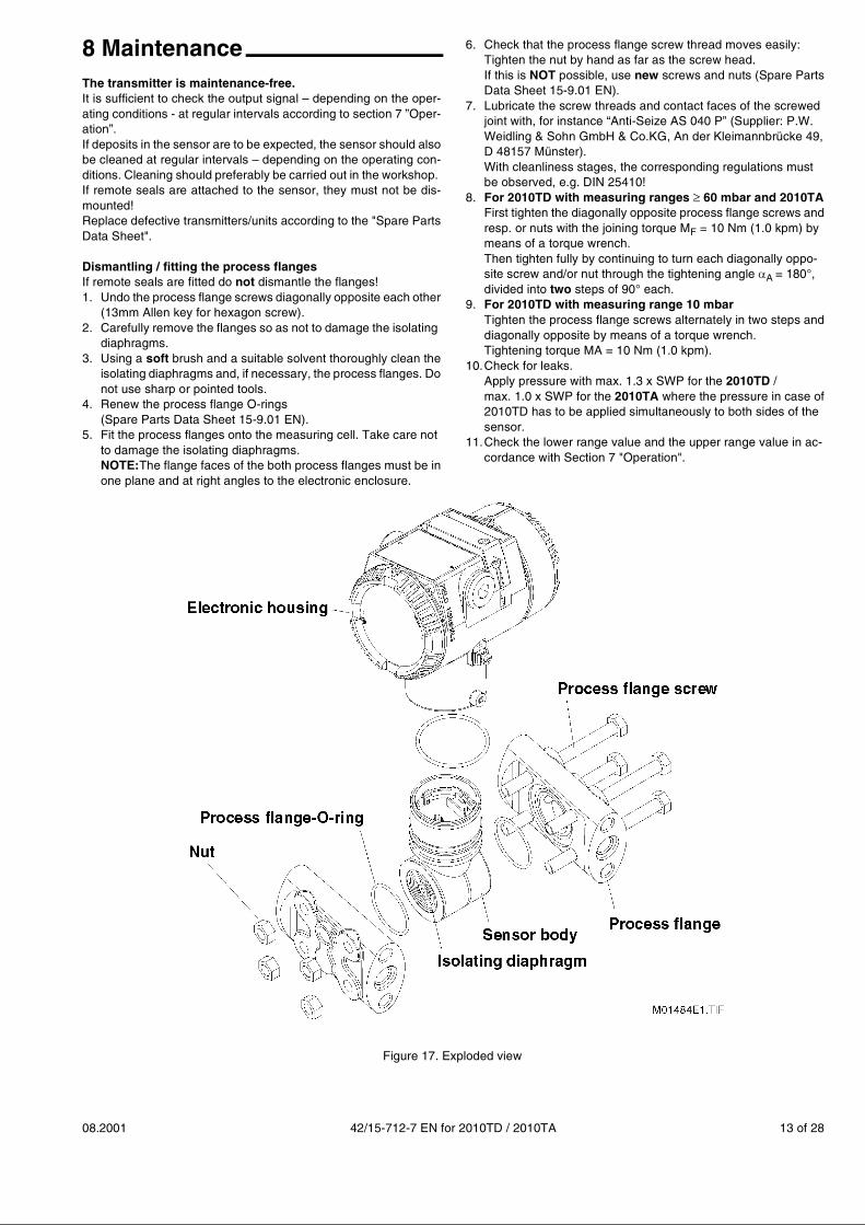
8 MaintenanceThe transmitter is maintenance-free.It is sufficient to check the output signal – depending on the oper-ating conditions - at regular intervals according to section 7 ”Oper-ation”. If deposits in the sensor are to be expected, the sensor should alsobe cleaned at regular intervals – depending on the operating con-ditions. Cleaning should preferably be carried out in the workshop. If remote seals are attached to the sensor, they must not be dis-mounted!Replace defective transmitters/units according to the "Spare PartsData Sheet".
Dismantling / fitting the process flangesIf remote seals are fitted do not dismantle the flanges!1. Undo the process flange screws diagonally opposite each other
(13mm Allen key for hexagon screw).2. Carefully remove the flanges so as not to damage the isolating
diaphragms.3. Using a soft brush and a suitable solvent thoroughly clean the
isolating diaphragms and, if necessary, the process flanges. Donot use sharp or pointed tools.
4. Renew the process flange O-rings(Spare Parts Data Sheet 15-9.01 EN).
5. Fit the process flanges onto the measuring cell. Take care not to damage the isolating diaphragms.NOTE:The flange faces of the both process flanges must be inone plane and at right angles to the electronic enclosure.
6. Check that the process flange screw thread moves easily:Tighten the nut by hand as far as the screw head. If this is NOT possible, use new screws and nuts (Spare PartsData Sheet 15-9.01 EN).
7. Lubricate the screw threads and contact faces of the screwed joint with, for instance “Anti-Seize AS 040 P” (Supplier: P.W.Weidling & Sohn GmbH & Co.KG, An der Kleimannbrücke 49,D 48157 Münster). With cleanliness stages, the corresponding regulations mustbe observed, e.g. DIN 25410!
8. For 2010TD with measuring ranges ��60 mbar and 2010TAFirst tighten the diagonally opposite process flange screws andresp. or nuts with the joining torque MF = 10 Nm (1.0 kpm) bymeans of a torque wrench.Then tighten fully by continuing to turn each diagonally oppo-site screw and/or nut through the tightening angle A = 180°,divided into two steps of 90° each.
9. For 2010TD with measuring range 10 mbarTighten the process flange screws alternately in two steps anddiagonally opposite by means of a torque wrench.Tightening torque MA = 10 Nm (1.0 kpm).
10.Check for leaks.Apply pressure with max. 1.3 x SWP for the 2010TD /max. 1.0 x SWP for the 2010TA where the pressure in case of2010TD has to be applied simultaneously to both sides of thesensor.
11.Check the lower range value and the upper range value in ac-cordance with Section 7 "Operation".
Figure 17. Exploded view
14 of 28 42/15-712-7 EN for 2010TD / 2010TA 08.2001
9 RepairsAttention: Explosion-proof transmitters may only be repaired bythe manufacturer, or they must be certified by an acknowledgedexpert after the repair has been carried out!Observe the pertinent safety regulations before, during and aftercommissioning. Disassemble the transmitter only to such extent as necessary forcleaning, checking, repairing and replacing the defective parts. Observe section 8 "Maintenance"!Sensor as well as sensor with attached remote seal can only be re-paired by the manufacturer.If the electronic housing has to be detached from the sensor / themeasuring cell, the electronic unit must be removed from the elec-tronic housing before in order to prevent a damage to the electron-ic unit. For this purpose, first of all the housing cover has to bescrewed off (attachment screw!, refer to figure 10), then remove apossibly existing LCD indicator from the electronic unit (loosen 2screws), unscrew the two captive screws of the electronic unit andremove same carefully from the electronic housing. Detach the twoplugs from the electronic unit (both plugs have got a mechanicalreverse battery protection and the smaller one additionally a me-chanical interlock: seize the plug on the front side between thumband forefinger and press the lock towards the plug, then pull off theplug from the socket). Put the electronic unit on a suitable pad. Un-screw the electronic housing from the sensor / the measuring cell.ReturnDefective transmitters/units are to be sent to the repair depart-ment, if possible stating the fault and its cause.Note: When ordering spare parts or instruments, please quote theserial number (F.-No.) of the original transmitter.Address:ABB Automation Systems GmbHDepartment SWMSchillerstraße 72D-32425 Minden
10 Technical DataMeasured value2010TD: Differential pressure, Absolute pressure2010TA: Absolute pressureMeasuring range (upper and lower range values)Lower range value (continuously adjustable)2010TD: - 100% to + 100% of the URL2010TA: 0% and + 100% of the URLUpper range value (continuously adjustable)Up to 100% of the URLSpansdp-sensor: The adjusted span must not be lower than the mini-mum range (recommendation for square root function: at least10% of the range).Measuring ranges
Code min. max. SWPA 50 Pa / 0.5 mbar 1 kPa / 10 mbar 6B 200 Pa / 2 mbar 6 kPa / 60 mbar 160...410C 400 Pa / 4 mbar 40 kPa / 400 mbar 160...410D 2.5 kPa / 25 mbar 250 kPa / 2.5 bar 160...410E 20 kPa / 0.2 bar 2 MPa / 20 bar 160...410G 100 kPa / 1 bar 10 MPa / 100 bar 160...410L 400 Pa / 4 mbar 40 kPa / 400 mbar 160
abs. abs.M 2.5 kPa / 25 mbar 250 kPa / 2.5 bar 160
abs. abs.N 20 kPa / 0.2 bar 2 MPa / 20 bar 160
abs. abs.
Code min. max. SWP (psi)A 0.2 inchH2O 4 inchH2O 90B 0.8 inchH2O 24 inchH2O 2300...6000C 1.6 inchH2O 160 inchH2O 2300...6000
D 10 inchH2O 1000 inchH2O) 2300...6000E 80 inchH2O 290 psi 2300...6000G 400 inchH2O 1450 psi 2300...6000L 1.6 inchH2O abs. 160 inchH2O abs. 2300M 10 inchH2O abs. 1000 inchH2O abs. 2300N 80 inchH2O abs. 290 psia 2300
pabs-sensor:Measuring range
Code1 41 MPa abs. / 410 bar abs. / 6000 psia
(0.6MPa / 6bar abs. / 90psi with 10mbar (4inchH2O) range)Output signalTransmitters with 4...20mASignal: analogue 4 ... 20 mAOutput signal limits: Imin = 3.5 mA, Imax = 22.5 mA
(configurable).Standard setting: Imin = 3.8 mA, Imax = 20.5 mAAlarm currentMin. alarm current: configurable from 3.5 mA to 4 mA,
standard setting: 3.6 mAMax. alarm current: configurable from 20 mA to 22.5 mA,
standard setting: 21 mAStandard setting: max. alarm currentLoadTransmitters with 4...20 mA
Imax = 20 ... 22.5 mA (configurable)Us = supply voltagemin. power supplyy: 10.5 VDC, 14 VDC with backlit LCD-indicatormin. load for digital communications > 250 OhmField Bus transmittersSignal: digital Transmission technique: acc. to IEC 61158-2Power supply: 10.2 VDC ... 32 V DCBase current: 14 mATransmission rate: 31.25 kbits/sPROFIBUS-PA: Version 3.0, Profile B for pressure
transmitters; Ident No.: 04C2 HEXFoundation Fieldbus: FF-890 / 891 ans FF-902 / 903CharacteristicLinear, square root, freely programmable with 20 reference points,x3/2 - and x5/2 - output functionAccuracyReference conditionsto DIN IEC 770Temperature: 20 °C (68 °F)Relative humidity: 65 %Atmospheric pressure: 1013mbar (1013 hPa, 14.7 psia)additional conditions:Separating diaphragm material “Hastelloy C“ 1), filll fluid “siliconeoil” and „linear output“All specifications are limits and relate to the output range or cali-brated range. The influences marked � relate to the measuringrange (URL) and are to be multiplied by the turn down factor (ratiorange (URL) / calibrated span). The turn down factor should bekept to a minimum.Conformity��for 2010TD and 2010TA, dp-sensor:terminal based, including hysteresis and the dead band 2)
Optional 2) (Order code: 5C9)
linear square root
0.075% 0.15%
linear square root
0.05% 0.1%
RUs 10 5V,–
Imax-------------------------------� in kOhm
08.2001 42/15-712-7 EN for 2010TD / 2010TA 15 of 28
for 2010TD, pabs-sensor:0.8 bar, with pabs-sensor 6 bar: 12 mbar(321 in.H2O, with pabs-sensor 90 psi: 4,82 in.H2O)Hysteresis 2)
Reproducibility0.01 %Warm-up time< 15 sRise timeThe time behaviour of this transmitter is composed of the rise timeof the sensor and an adjustable integration time constant of theA/D converter. A high time constant results into a high resolution,e.g. required for a high span ratio, and at the same time into a high-er rise time for the output signal. A low time constant means a low-er resolution, but a shorter rise time and thus a faster reaction timeof the transmitter. In case of the default integration time constantthe values shown in the table below result.
additional adjustable time constant 0...60sThe effect appearing at the output for non-linear output (e.g.square root function) depends on the function and is to be calcu-lated accordingly.Long-term drift� 0.05% per 12 monthsEffect of position� on zero approx. 3.5 mbar(1.4 in.H2O) x sin °
(° = angular deviation indegreesfrom the nominal mounting position)
Ambient temperature effect (dp-sensor)Thermal change (-40°C ... +80°C)3)4) / (-104 °F ... +176 °F)3)4)
� on zero 0.1 %on span 0.1 %
Temperature coefficient (-40°C...+80°C)3)4) / (-104°F...+176°F)3)4)
�� on zero 0.04 % per 10°C (50 °F)on span 0.04 % per 10°C (50 °F)
Ambient temperature effect (pabs-sensor (2010TD))Thermal change (-40°C ... +80°C)3)4) / (-104 °F ... +176 °F)3)4)
� on zero 0.4 bar (160 in.H2O)6 mbar with 6 bar pabs-sensor(2.4 in.H2O with 90 psi-sensor)
Thermal change (-20°C ... +60°C)3)4) / (-68°F...+140°F)3)4)
� on span 2 bar (803 in.H2O)30 mbar with 6 bar pabs-sensor(12 in.H2O with 90 psi-sensor)
Thermal change (-40°C ... +80°C)3)4) / (-104°F...+176°F)3)4)
� on span 3 bar (1204 in.H2O)45 mbar with 6 bar pabs-sensor(18 in.H2O with 90 psi-sensor)
Static pressure effectMessbereich 10 mbar ��60 mbar 100 bar
�4 in.H2O�� ����24 in.H2O�� (1450 psi)
� on zero 0.05% /1 bar 0.05% / 100bar 0.1%/100baron span 0.05% /1 bar 0.05% / 100bar 0.1%/100bar
Effect of electro-magnetic interference�� 0.05%
1) with Tantalum, Monel or Gold Plated Isolating Diaphragm, thefactor 1.5 is to be taken into account with static pressure andambient temperature effect with conformity
2) additionally with turn-down factor > 1:10
3) with range 10mbar / 100 bar: -20 °C ... +60 °C (4 in.H2O / 1450 psi: (-68°F...+140°F)
4) with carbon fluoride filling liquid: -20°C ... +80°C(-68°F ... +176°F)
Ambient conditionsAmbient temperature-40 °C ... +85 °C (with O-ring Viton: -20 °C ... +85 °C)(-104°F ... +185°F) (with O-ring Viton: -68°F ... +185°F),Observe approvals for explosion-protected transmitters.Storage temperature / transport temperature-50 °C ... +85 °C, with LCD-indicator -40 °C ... +85 °C(-122°F ... +185°F, with LCD-indicator -104°F ... +185°F)HumidityRelative humidity: 95% annual averageCondensation, icing: admissibleProtection classIP 67 acc. to EN 60 529 (=NEMA Standard Type 6);with Han 8U plug: IP 65 (=NEMA Standard Type 4X)Protective varnishepoxy resin, greywhite, RAL 9002Shock resistantAcceleration: 50gDuration: 11msVibration resistance2g up to 1000 Hz, with amplifier housing made of “stainless steel”are valid restricted values (on request)Electromagnetic compatibility (EMC)to EN 50 082-2Definition: Class 3Radio suppression (EN 55 011): Limit class BFulfills NAMUR recommendation.Process conditionsTemperature limits-50 °C ... + 120 °C (-122°F ... +248°F), at process connectionto +400 °C (752 °F) in conjunction with remote seals.with gasket:��O-rings Viton (fluorocaoutchouc (FPM)) -20 °C ... +120 °C
(-68°F ... +248°F)Pressure limits2010TD: Static pressure limits: from 3.5 kPa abs. (14 in.H2O abs.)to the nominal pressure (SWP),proof pressure up to 1.5-times the nominal pressure simultaleouslyon both sides of the transmitter admissible.2010TA: Static pressure limits: from full vacuum up to the nominalpressure (SWP),proof pressures up to 1.0-times the nominal pressure admissible.Overload limitOne-sided overload up to the rated pressure.Weight3.5 kg
linear square root
0.05% 0.1%
range linearsquare
root
freelyprogram-
mablefunction
turn down factor
��1 : 10> 1 : 10
up to��1 : 20
> 1 : 20up to
��1 : 40> 1: 40
10mbar(4in.H2O)
~ 2.0 s ~ 2.2 s ~ 2.6 s ~ 3.1 s ~ 2.6 s ~ 2.2 s
60mbar(25in.H2O)
~ 0.8 s ~ 1.0 s ~ 1.4 s ~ 1.9 s ~ 1.4 s ~ 1.0 s
�400mbar(160in.H2O)
~ 0.3 s ~ 0.5 s ~ 0.9 s ~ 1.4 s ~ 0.9 s ~ 0.5 s
± 0.005�measuring range
adjusted span------------------------------------------ 0.05 �–� %
16 of 28 42/15-712-7 EN for 2010TD / 2010TA 08.2001
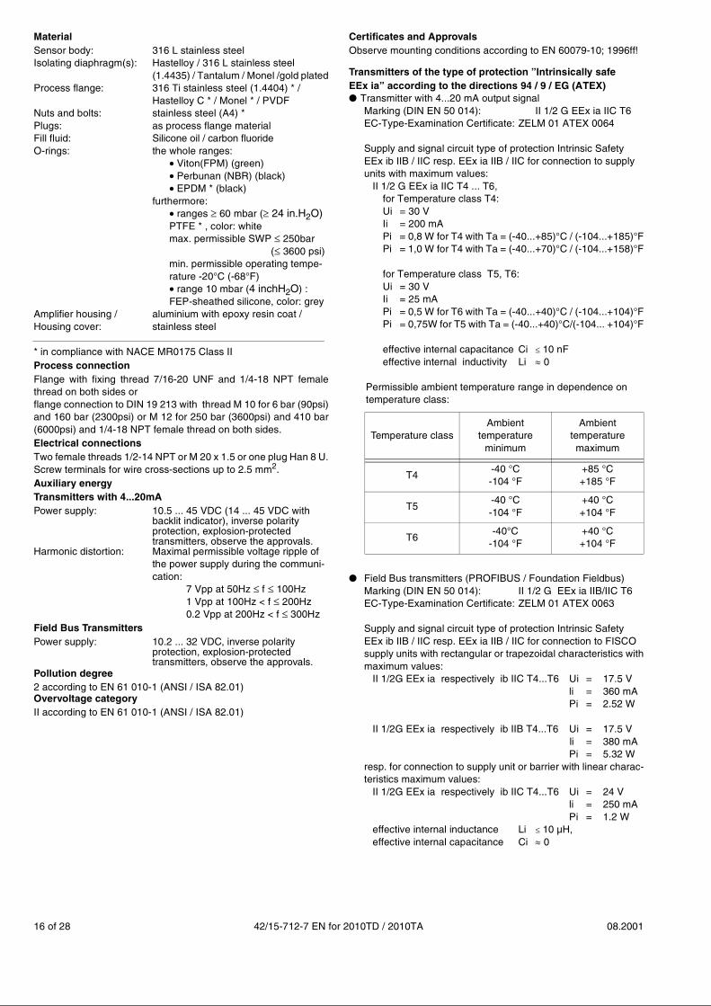
MaterialSensor body: 316 L stainless steelIsolating diaphragm(s): Hastelloy / 316 L stainless steel
(1.4435) / Tantalum / Monel /gold platedProcess flange: 316 Ti stainless steel (1.4404) * /
Hastelloy C * / Monel * / PVDFNuts and bolts: stainless steel (A4) *Plugs: as process flange materialFill fluid: Silicone oil / carbon fluorideO-rings: the whole ranges:
��Viton(FPM) (green)��Perbunan (NBR) (black)��EPDM * (black)
furthermore:��ranges � 60 mbar (� 24 in.H2O) PTFE * , color: whitemax. permissible SWP 250bar
( 3600 psi)min. permissible operating tempe-rature -20°C (-68°F)��range 10 mbar (4 inchH2O) :FEP-sheathed silicone, color: grey
Amplifier housing / aluminium with epoxy resin coat /Housing cover: stainless steel
* in compliance with NACE MR0175 Class IIProcess connectionFlange with fixing thread 7/16-20 UNF and 1/4-18 NPT femalethread on both sides orflange connection to DIN 19 213 with thread M 10 for 6 bar (90psi)and 160 bar (2300psi) or M 12 for 250 bar (3600psi) and 410 bar(6000psi) and 1/4-18 NPT female thread on both sides.Electrical connectionsTwo female threads 1/2-14 NPT or M 20 x 1.5 or one plug Han 8 U.Screw terminals for wire cross-sections up to 2.5 mm2.Auxiliary energyTransmitters with 4...20mAPower supply: 10.5 ... 45 VDC (14 ... 45 VDC with backlit indicator), inverse polarity
protection, explosion-protectedtransmitters, observe the approvals.
Harmonic distortion: Maximal permissible voltage ripple ofthe power supply during the communi-cation:
7 Vpp at 50Hz f 100Hz 1 Vpp at 100Hz < f 200Hz 0.2 Vpp at 200Hz < f 300Hz
Field Bus TransmittersPower supply: 10.2 ... 32 VDC, inverse polarity
protection, explosion-protectedtransmitters, observe the approvals.
Pollution degree2 according to EN 61 010-1 (ANSI / ISA 82.01)Overvoltage categoryII according to EN 61 010-1 (ANSI / ISA 82.01)
Certificates and ApprovalsObserve mounting conditions according to EN 60079-10; 1996ff!
Transmitters of the type of protection ”Intrinsically safeEEx ia” according to the directions 94 / 9 / EG (ATEX)● �Transmitter with 4...20 mA output signal
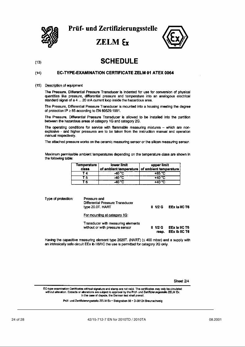
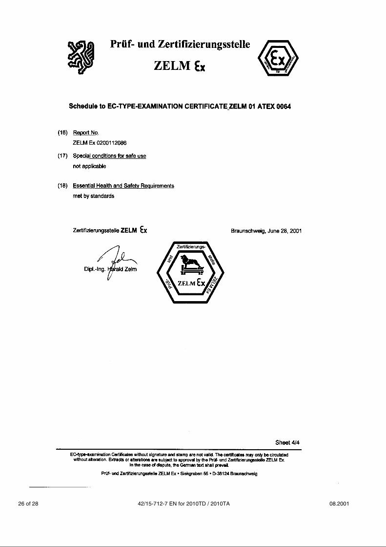
Marking (DIN EN 50 014): II 1/2 G EEx ia IIC T6EC-Type-Examination Certificate: ZELM 01 ATEX 0064
Supply and signal circuit type of protection Intrinsic Safety EEx ib IIB / IIC resp. EEx ia IIB / IIC for connection to supplyunits with maximum values:
II 1/2 G EEx ia IIC T4 ... T6, for Temperature class T4:Ui = 30 V Ii = 200 mA
Pi = 0,8 W for T4 with Ta = (-40...+85)°C / (-104...+185)°FPi = 1,0 W for T4 with Ta = (-40...+70)°C / (-104...+158)°F
for Temperature class T5, T6:Ui = 30 VIi = 25 mAPi = 0,5 W for T6 with Ta = (-40...+40)°C / (-104...+104)°FPi = 0,75W for T5 with Ta = (-40...+40)°C/(-104... +104)°F
effective internal capacitance Ci � 10 nFeffective internal inductivity Li � 0
Permissible ambient temperature range in dependence ontemperature class:
● � Field Bus transmitters (PROFIBUS / Foundation Fieldbus)Marking (DIN EN 50 014): II 1/2 G EEx ia IIB/IIC T6EC-Type-Examination Certificate: ZELM 01 ATEX 0063
Supply and signal circuit type of protection Intrinsic Safety EEx ib IIB / IIC resp. EEx ia IIB / IIC for connection to FISCOsupply units with rectangular or trapezoidal characteristics withmaximum values:
II 1/2G EEx ia respectively ib IIC T4...T6 Ui = 17.5 V li = 360 mA
Pi = 2.52 W
II 1/2G EEx ia respectively ib IIB T4...T6 Ui = 17.5 Vli = 380 mAPi = 5.32 W
resp. for connection to supply unit or barrier with linear charac-teristics maximum values:
II 1/2G EEx ia respectively ib IIC T4...T6 Ui = 24 V li = 250 mA Pi = 1.2 W
effective internal inductance Li � 10 µH,effective internal capacitance Ci � 0
Temperature classAmbient
temperature minimum
Ambient temperature maximum
T4-40 °C-104 °F
+85 °C+185 °F
T5-40 °C-104 °F
+40 °C+104 °F
T6-40°C
-104 °F+40 °C+104 °F
08.2001 42/15-712-7 EN for 2010TD / 2010TA 17 of 28
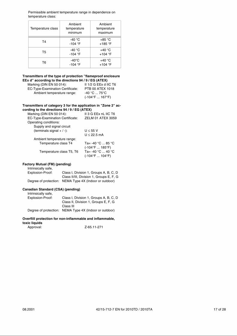
Permissible ambient temperature range in dependence ontemperature class:
Transmitters of the type of protection ”flameproof enclosure EEx d” according to the directions 94 / 9 / EG (ATEX)
Marking (DIN EN 50 014): II 1/2 G EEx d IIC T6EC-Type-Examination Certificate: PTB 00 ATEX 1018
Ambient temperature range: -40 °C ... 75°C (-104°F ... 167°F)
Transmitters of category 3 for the application in "Zone 2" ac-cording to the directions 94 / 9 / EG (ATEX)
Marking (DIN EN 50 014): II 3 G EEx nL IIC T6EC-Type-Examination Certificate: ZELM 01 ATEX 3059Operating conditions:
Supply and signal circuit(terminals signal + / -): U 55 V
U 22.5 mAAmbient temperature range:
Temperature class T4 Ta= -40 °C ... 85 °C(-104°F ... 185°F)
Temperature class T5, T6 Ta= -40 °C ... 40 °C(-104°F ... 104°F)
Factory Mutual (FM) (pending)Intrinsically safe,Explosion-Proof: Class I, Division 1, Groups A, B, C, D
Class II/III, Division 1, Groups E, F, GDegree of protection: NEMA Type 4X (Indoor or outdoor)
Canadian Standard (CSA) (pending)Intrinsically safe,Explosion-Proof: Class I, Division 1, Groups A, B, C, D
Class II, Division 1, Groups E, F, GClass III
Degree of protection: NEMA Type 4X (Indoor or outdoor)
Overflill protection for non-inflammable and inflammable,toxic liquids
Approval: Z-65.11-271
Temperature classAmbient
temperature minimum
Ambient temperature maximum
T4-40 °C-104 °F
+85 °C+185 °F
T5-40 °C-104 °F
+40 °C+104 °F
T6-40°C
-104 °F+40 °C+104 °F
18 of 28 42/15-712-7 EN for 2010TD / 2010TA 08.2001
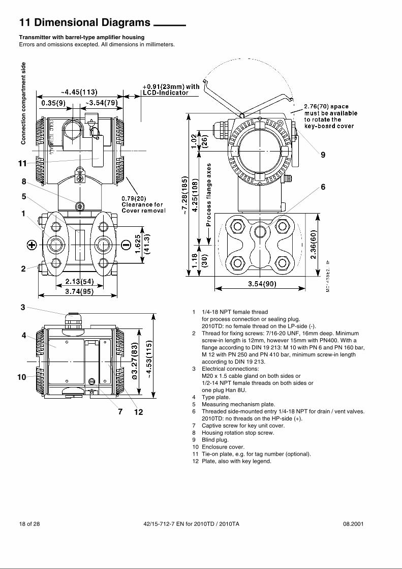
11 Dimensional DiagramsTransmitter with barrel-type amplifier housingErrors and omissions excepted. All dimensions in millimeters.
Co
nn
ecti
on
co
mp
artm
ent
sid
e
4
2
1
12
3
56
8
911
10
7
1111
1 1/4-18 NPT female threadfor process connection or sealing plug.2010TD: no female thread on the LP-side (-).
2 Thread for fixing screws: 7/16-20 UNF, 16mm deep. Minimumscrew-in length is 12mm, however 15mm with PN400. With aflange according to DIN 19 213: M 10 with PN 6 and PN 160 bar,M 12 with PN 250 and PN 410 bar, minimum screw-in lengthaccording to DIN 19 213.
3 Electrical connections: M20 x 1.5 cable gland on both sides or1/2-14 NPT female threads on both sides orone plug Han 8U.
4 Type plate.5 Measuring mechanism plate.6 Threaded side-mounted entry 1/4-18 NPT for drain / vent valves.
2010TD: no threads on the HP-side (+).7 Captive screw for key unit cover.8 Housing rotation stop screw.9 Blind plug.10 Enclosure cover.11 Tie-on plate, e.g. for tag number (optional).12 Plate, also with key legend.
08.2001 42/15-712-7 EN for 2010TD / 2010TA 19 of 28
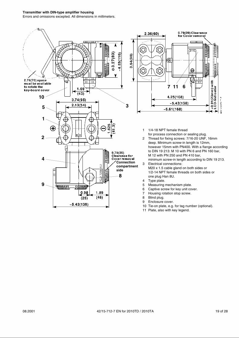
Transmitter with DIN-type amplifier housingErrors and omissions excepted. All dimensions in millimeters.
11
2
1
5 3
67
4
9
8
10
Connectioncompartment
1 1/4-18 NPT female threadfor process connection or sealing plug.
2 Thread for fixing screws: 7/16-20 UNF, 16mmdeep. Minimum screw-in length is 12mm,however 15mm with PN400. With a flange accordingto DIN 19 213: M 10 with PN 6 and PN 160 bar,M 12 with PN 250 and PN 410 bar,minimum screw-in length according to DIN 19 213.
3 Electrical connections: M20 x 1.5 cable gland on both sides or1/2-14 NPT female threads on both sides orone plug Han 8U.
4 Type plate.5 Measuring mechanism plate.6 Captive screw for key unit cover.7 Housing rotation stop screw.8 Blind plug.9 Enclosure cover.10 Tie-on plate, e.g. for tag number (optional).11 Plate, also with key legend.
side
20 of 28 42/15-712-7 EN for 2010TD / 2010TA 08.2001
Errors and omissions excepted. All dimensions in millimeters.
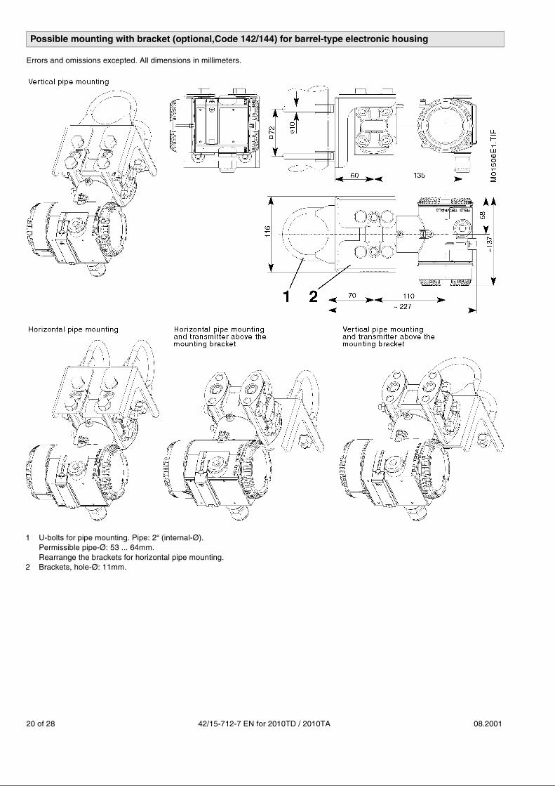
1 U-bolts for pipe mounting. Pipe: 2“ (internal-Ø).Permissible pipe-Ø: 53 ... 64mm.Rearrange the brackets for horizontal pipe mounting.
2 Brackets, hole-Ø: 11mm.
Possible mounting with bracket (optional,Code 142/144) for barrel-type electronic housing

08.2001 42/15-712-7 EN for 2010TD / 2010TA 21 of 28
Errors and omissions excepted. All dimensions in millimeters.
Errors and omissions excepted. All dimensions in millimeters.
Possible mounting with bracket (optional,Code 14E/14F) for barrel-type electronic housing
1 U-bolts for pipe mounting. Pipe: 2“ (internal-Ø).Permissible pipe-Ø: 53 ... 64mm.Rearrange the brackets for horizontal pipemounting.
2 Brackets, hole-Ø: 9mm.
Possible mounting with bracket (optional,Code 14D) for barrel-type electronic housing
1 U-bolts for pipe mounting. Pipe: 2“ (internal-Ø).Permissible pipe-Ø: 53 ... 64mm.Rearrange the brackets for horizontal pipemounting.
2 Brackets, hole-Ø: ~10mm.
22 of 28 42/15-712-7 EN for 2010TD / 2010TA 08.2001

08.2001 42/15-712-7 EN for 2010TD / 2010TA 23 of 28
24 of 28 42/15-712-7 EN for 2010TD / 2010TA 08.2001

08.2001 42/15-712-7 EN for 2010TD / 2010TA 25 of 28
26 of 28 42/15-712-7 EN for 2010TD / 2010TA 08.2001

08.2001 42/15-712-7 EN for 2010TD / 2010TA 27 of 28

ABB Automation Products GmbHSchillerstraße 72D-32425 MindenTel. +49(0)571 830-0Fax +49(0)571 830-1846http://www.abb.com
Technical revision reservedPrinted in the Fed. Rep. of Germany
42/15-712-7 EN 08.2001
This Technical Documentation is subject to copyright. Translation, reproduction and distribution in any form – even as a revised versionor in extracts – are forbidden without prior permission of the holder of rights; particularly reprint, photomechanical or electronic reproduc-tion and storage in data processing systems or data networks are not allowed. Offenders will be prosecuted and civil action brought againstthem.