multi-photon microscopy: applications and theory … and mp… · multi-photon microscopy:...
TRANSCRIPT

MULTI-PHOTON MICROSCOPY:APPLICATIONS AND THEORY
PART I
JAMES LOPEZ PH.D.
NATIONAL SALES APPLICATIONS SPECIALIST
FLUOVIEW LASER SCANNING CONFOCALAND MULTIPHOTON
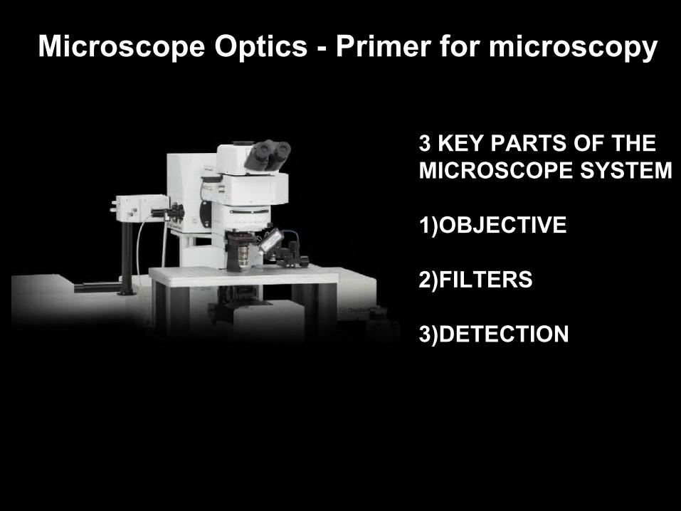
Microscope Optics - Primer for microscopy
3 KEY PARTS OF THEMICROSCOPE SYSTEM
1)OBJECTIVE
2)FILTERS
3)DETECTION

Microscope Optics - Primer for microscopy

Lateral and axial chromatic aberration

Spherical aberration

Refractive Index
refractive index =
Speed of light in a vacuumSpeed of light in medium
Air n = 1.00
Water n = 1.33
Silicone Oil n = 1.40
Glycerol n = 1.47
Immersion n = 1.52Oil
TIRF n = 1.78Oil

Numerical Aperature Numerical aperature (NA) =
n (sin (µ))
Theoretical maximum for µ = 90º
n = refractive index
40x UPlanSApo 0.95NA Dry
n = 1.00 AIR
1.00 (sin (90)) = 1.00 NATheoretical maximum
40x UPlanSApo 0.95NA Dry

40x Dry UPlanSApoN 0.95NA is a great objective,but how does this compare to the 40x Oil UPlanFlN 1.3NA?
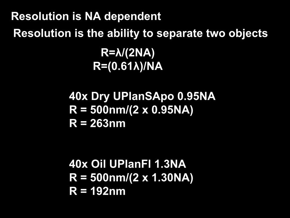
R=λ/(2NA)R=(0.61λ)/NA
Resolution is NA dependent
Resolution is the ability to separate two objects
40x Dry UPlanSApo 0.95NAR = 500nm/(2 x 0.95NA)R = 263nm
40x Oil UPlanFl 1.3NAR = 500nm/(2 x 1.30NA)R = 192nm
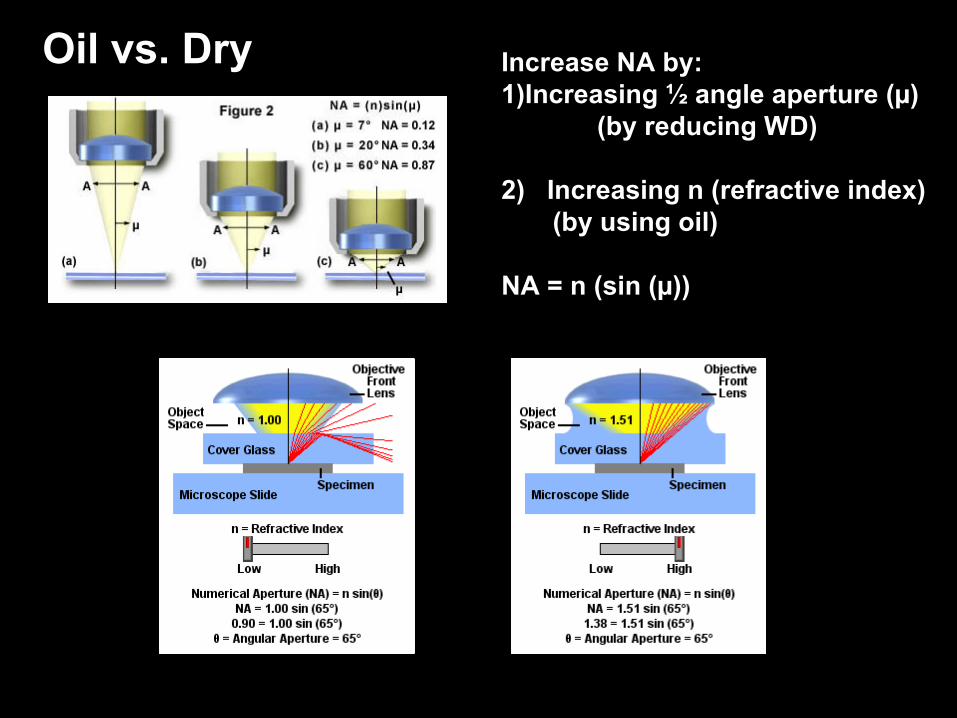
Oil vs. Dry Increase NA by:1)Increasing ½ angle aperture (µ)
(by reducing WD)
2) Increasing n (refractive index) (by using oil)
NA = n (sin (µ))

Numerical Aperature
High NAShallow depth of field (short focal distance low F stop)(Thin optical slice)Shorter working distance( Light comes to a focus close to the
objective face)
Low NADeep depth of field(Thick optical slice)Long working distance( Light comes to a focus far from the objective face)
Why would someone want a low NA lens?
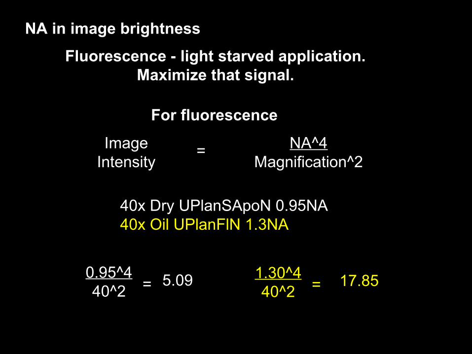
NA in image brightness
Fluorescence - light starved application.Maximize that signal.
ImageIntensity
= NA^4Magnification^2
For fluorescence
40x Dry UPlanSApoN 0.95NA40x Oil UPlanFlN 1.3NA
0.95^440^2 = 5.09 1.30^4
40^2 = 17.85
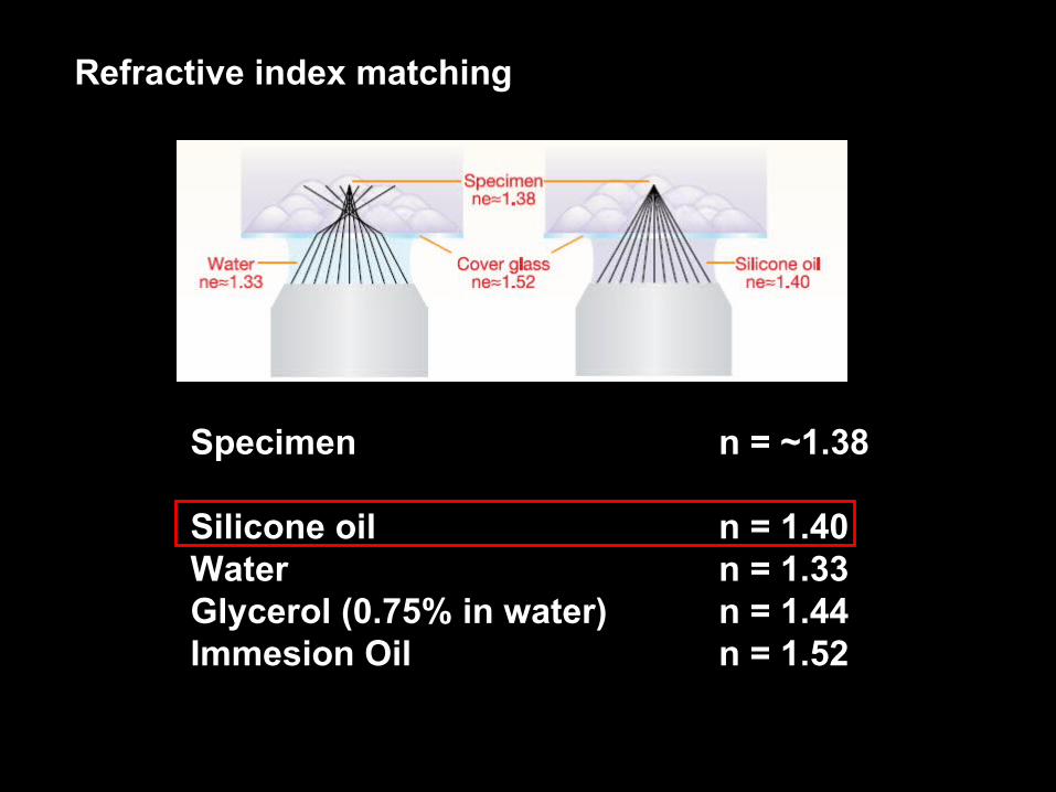
Refractive index matching
Specimen n = ~1.38
Silicone oil n = 1.40Water n = 1.33Glycerol (0.75% in water) n = 1.44Immesion Oil n = 1.52

40x UPlanSApo Silicone Oil Objective
NA - 1.25WD 300 micronsRefractive index matchingChromatically correctedSpherical aberration correction collar
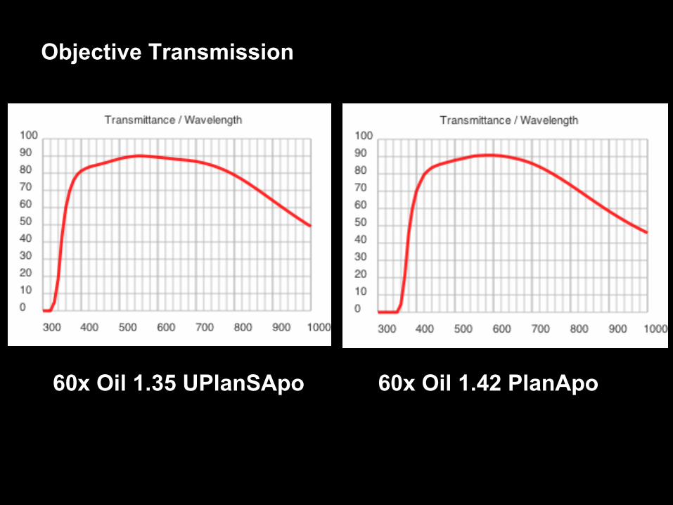
Objective Transmission
60x Oil 1.35 UPlanSApo 60x Oil 1.42 PlanApo

FLUORESCENT MINERALS
UV excitation/absorbanceHigh energy short wavelengths
Red-shifted emission Lower energy long wavelengths
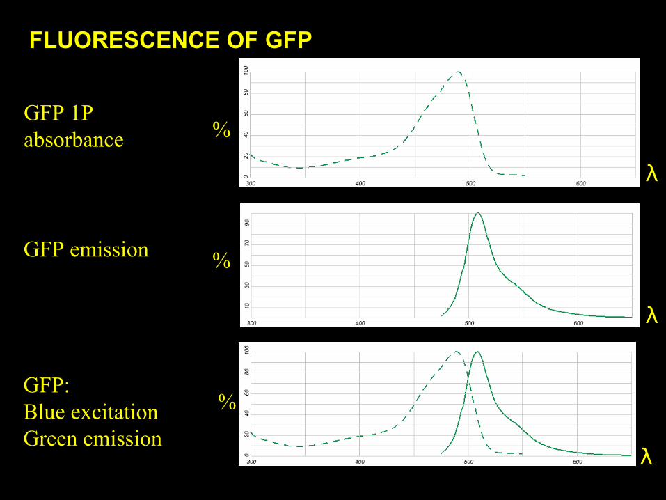
FLUORESCENCE OF GFP
GFP 1Pabsorbance
GFP emission
λ
λ
λ
GFP:Blue excitationGreen emission
%
%
%
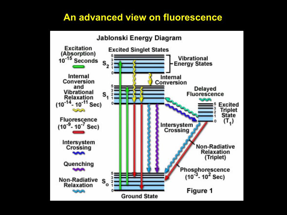
An advanced view on fluorescence
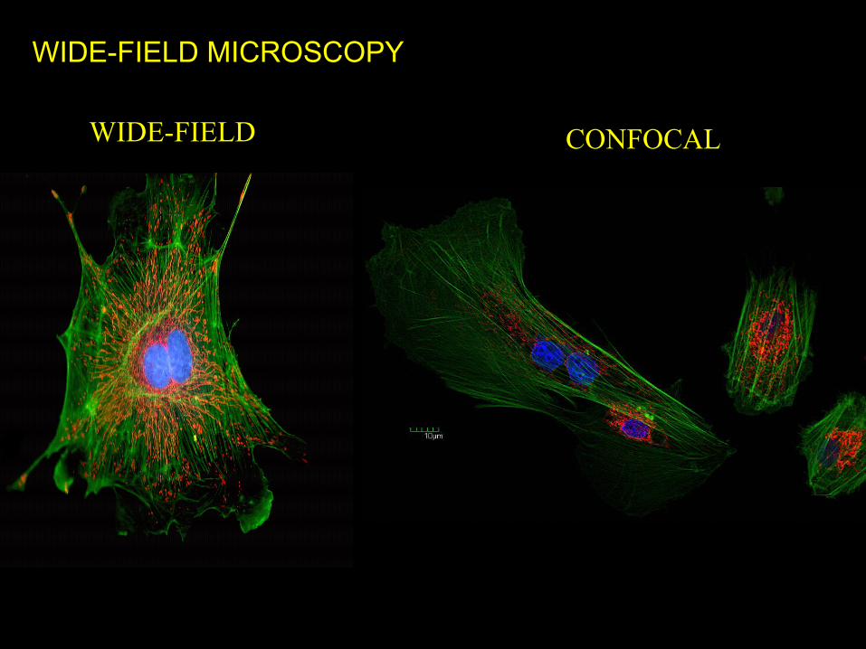
WIDE-FIELD MICROSCOPY
WIDE-FIELD CONFOCAL
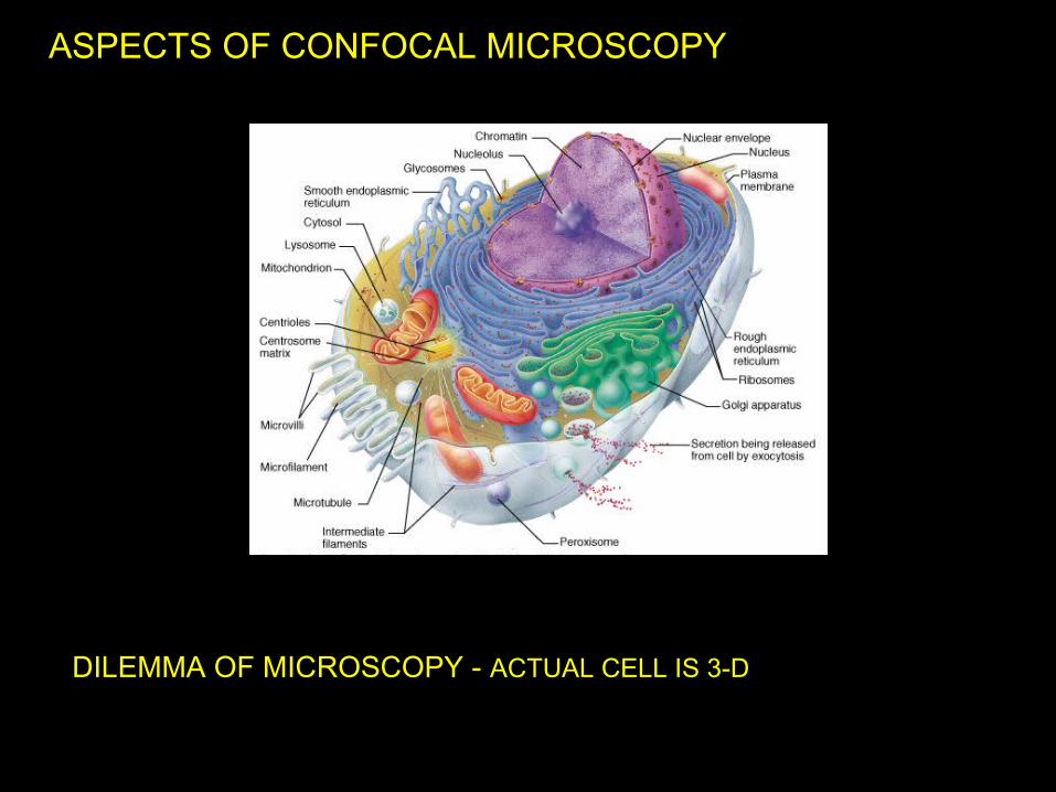
ASPECTS OF CONFOCAL MICROSCOPY
DILEMMA OF MICROSCOPY - ACTUAL CELL IS 3-D

Spinning DiskConfocal
SectionDepth
Background
Background
Wide-field Epi-Fluorescence
LaserScanningConfocal TIRF
Fluorescence Imaging Modalities: Optical Sectioning

LASER SCANNING CONFOCAL FOR OPTICAL SECTIONING
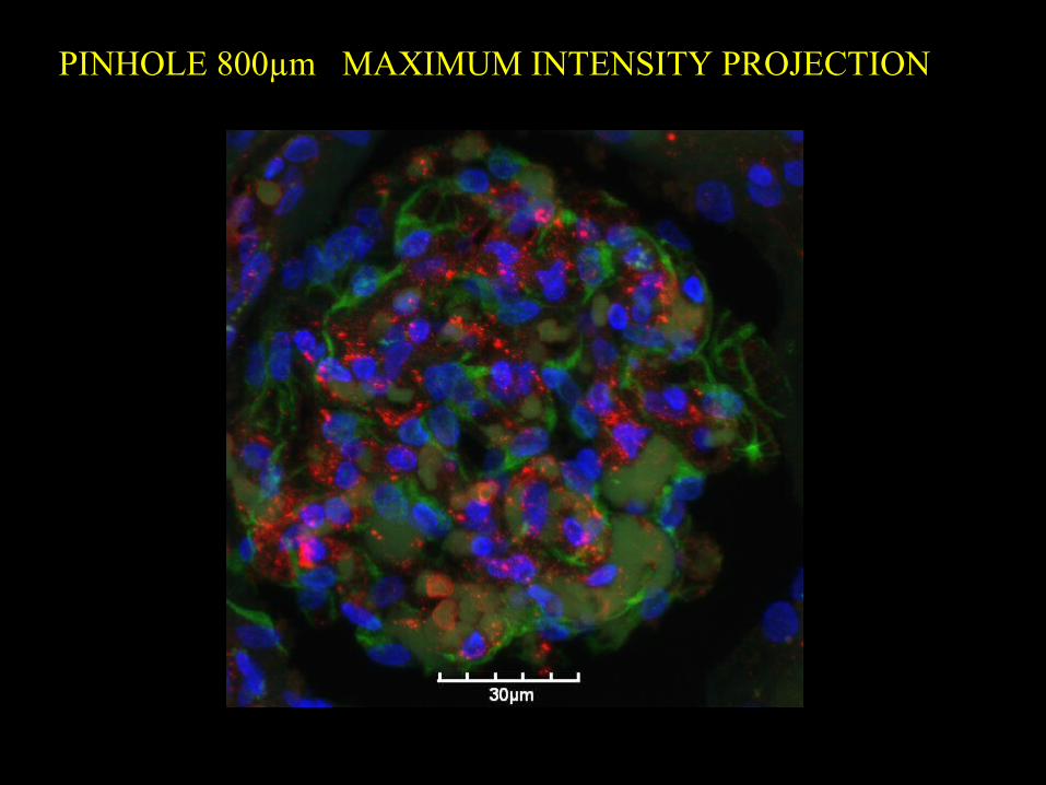
PINHOLE 800µm MAXIMUM INTENSITY PROJECTION
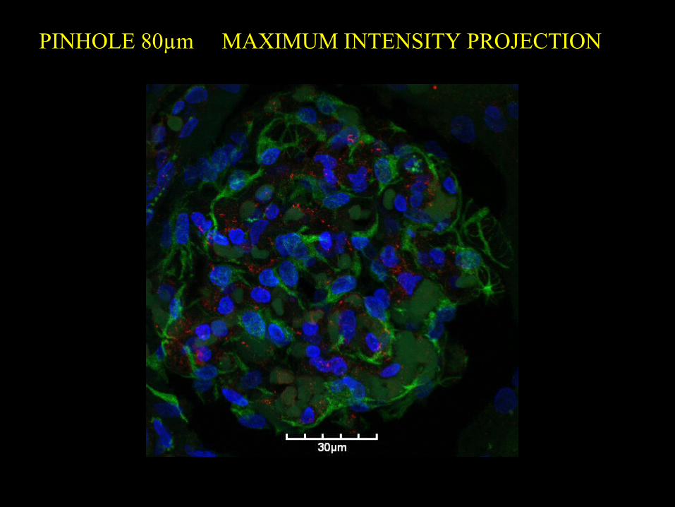
PINHOLE 80µm MAXIMUM INTENSITY PROJECTION

Epi-Fluorescence
WIDE-FIELD FLUORESCENCE IMAGE OF LOBELIA

Disk Confocal
SPINNING DISK CONFOCAL IMAGE OF LOBELIA

Phase Phase
DIC Nomarski DIC Nomarski
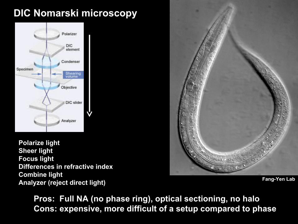
DIC Nomarski microscopy
Pros: Full NA (no phase ring), optical sectioning, no haloCons: expensive, more difficult of a setup compared to phase
Polarize lightSheer lightFocus lightDifferences in refractive indexCombine lightAnalyzer (reject direct light)
Fang-Yen Lab

Olympus FV1000MPE Multi-Photon Imaging System

FluoView FV1000 Overview Visible Confocal Features
Main Scanner : FL3CH + Transmitted detectorSIM Scanner: A second independent, but fully
synchronized laser scanner incorporated in a single compact design for simultaneous laser stimulation and observation.
Lasers: Multi-line Ar ( 458, 488, 515nm ) HeNe ( 543 )
Laser Diode (405, 440, 473, 559, 635) AOTF: standard equippedTwo types of Detectors: Filter, SpectralApplicable Microscopes: IX83 , BX61 , BX61WI
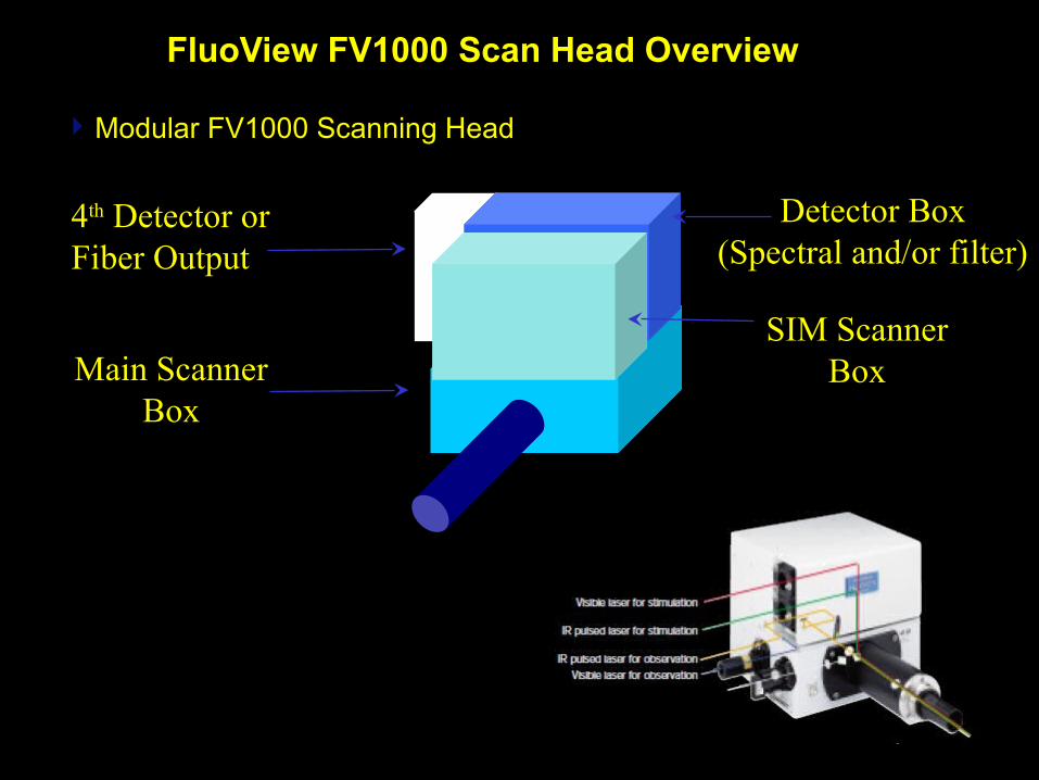
FluoView FV1000 Scan Head Overview
Modular FV1000 Scanning Head
Detector Box(Spectral and/or filter)
Main ScannerBox
SIM ScannerBox
4th Detector orFiber Output
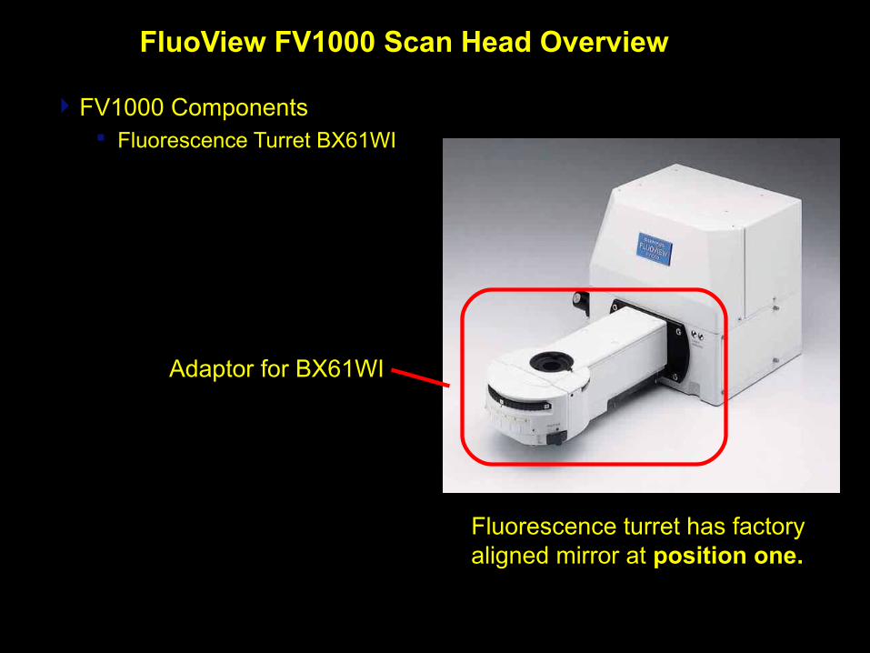
FluoView FV1000 Scan Head Overview
FV1000 Components Fluorescence Turret BX61WI
Fluorescence turret has factory aligned mirror at position one.
Adaptor for BX61WI

FluoView FV1000 Scan Head Overview
FV1000 Components Fiber Port - Fiber coupling output
• compatible fiber core 100-125μm
Fiber fluorescence light output for FLIM or spectrophotometer, etc.

FluoView FV1000 Overview
SIM Scanner Applications Photobleaching
FLIP fluorescence loss in photobleaching
FRAP fluorescence recovery after photobleaching
FRET by acceptor photobleaching Photoconversion Photoactivation Uncaging
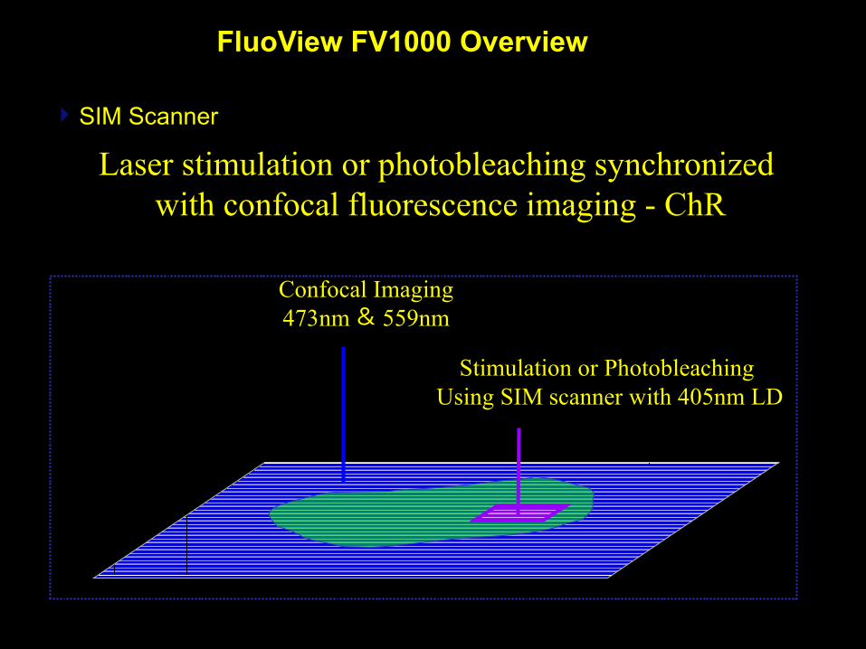
FluoView FV1000 Overview
SIM Scanner
Stimulation or Photobleaching Using SIM scanner with 405nm LD
Confocal Imaging473nm & 559nm
Laser stimulation or photobleaching synchronized with confocal fluorescence imaging - ChR

FluoView FV1000 Overview
SIM Scanner Tornado scan for rapid photobleaching or activation
Tornado Scan Conventional Scan
Laser on and offNon stop illumination!
Fast results with no recovery during fly-back

FluoView FV1000 Overview
SIM Scanner
156 msec/frame500 frames 80ms Tornado bleach
Bleach is completedwithin one frame and recovery starts.
Pyramidal Neuron Cell

FluoView FV1000 Transmitted Overview
FV1000 Components Transmitted light detection system suitable for visible
to near IR

FluoView FV1000 Laser Overview
• Basic SpecificationsFV1000 Components
Laser Combiners
Original Combiner
Current Dual Combiner Current Single Combiner
FluoView FV1000 Overview
Spectral Un-mixing Applications
Spectral Un-mixing
CFP, GFP
GFP, YFP
Auto-fluorescence background removal
Separate dyes with overlapping excitation spectra
Variable Band Pass Filter Optimize detection band widthNew dyes, e.g.quantum dots,GFP variants
Quantitative Fluorescence Imaging FRET analysis free of bleed through
FluoView FV1000 Overview
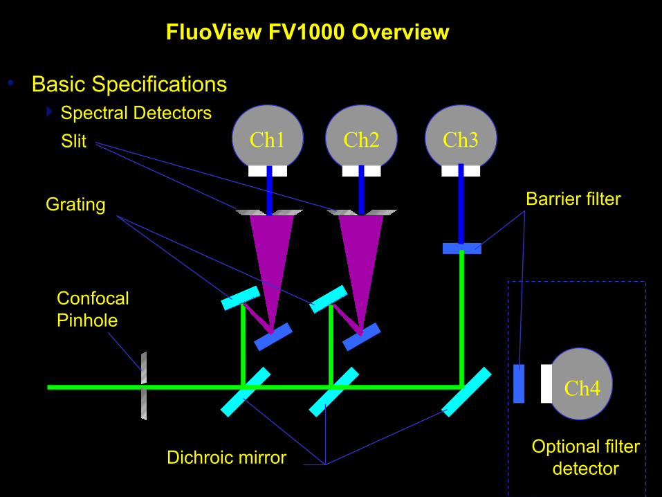
• Basic SpecificationsSpectral Detectors
Ch1 Ch2 Ch3
Ch4
Grating
Dichroic mirror
Barrier filter
Slit
ConfocalPinhole
Optional filterdetector
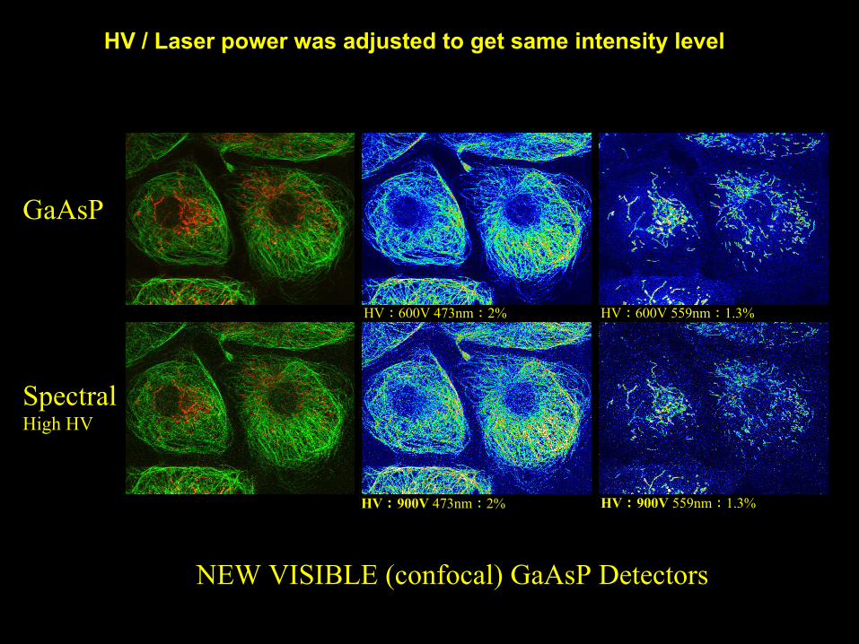
HV / Laser power was adjusted to get same intensity level
HV : 600V 473nm : 2% HV : 600V 559nm : 1.3%
HV : 900V 473nm : 2% HV : 900V 559nm : 1.3%
GaAsP
SpectralHigh HV
NEW VISIBLE (confocal) GaAsP Detectors

Comparison of Signal to Noise at Similar Level of Brightness
HV : 600V 473nm :13%
HV : 900V 473nm :13%
Visible GaAsP DetectorSpectral DetectorHigh HV(490 - 590nm)
Brain slice sample treated by SCALEVIEW-A2

Excited singlet state transition to long lived excited triplet stateROS and chemical modifications lead to destruction of fluorochrome
Reduce excitation energy. Increase sensitivity.
Photobleaching
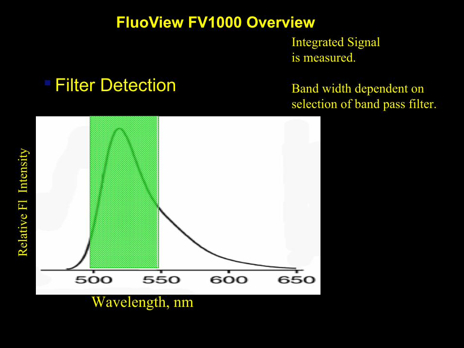
FluoView FV1000 Overview
Filter Detection
Integrated Signalis measured.
Band width dependent on selection of band pass filter.
Wavelength, nm
Rel
ativ
e F
l In
tens
ity
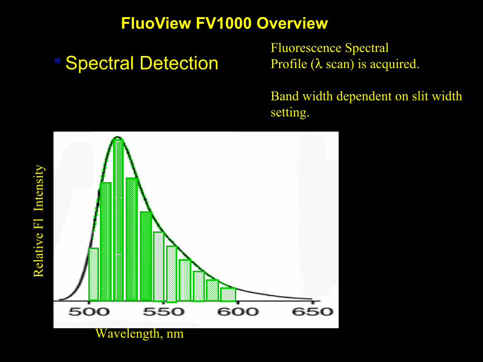
FluoView FV1000 Overview
Spectral DetectionFluorescence SpectralProfile ( scan) is acquired.
Band width dependent on slit width setting.
Wavelength, nm
Rel
ativ
e F
l In
tens
ity

FluoView FV1000 Overview
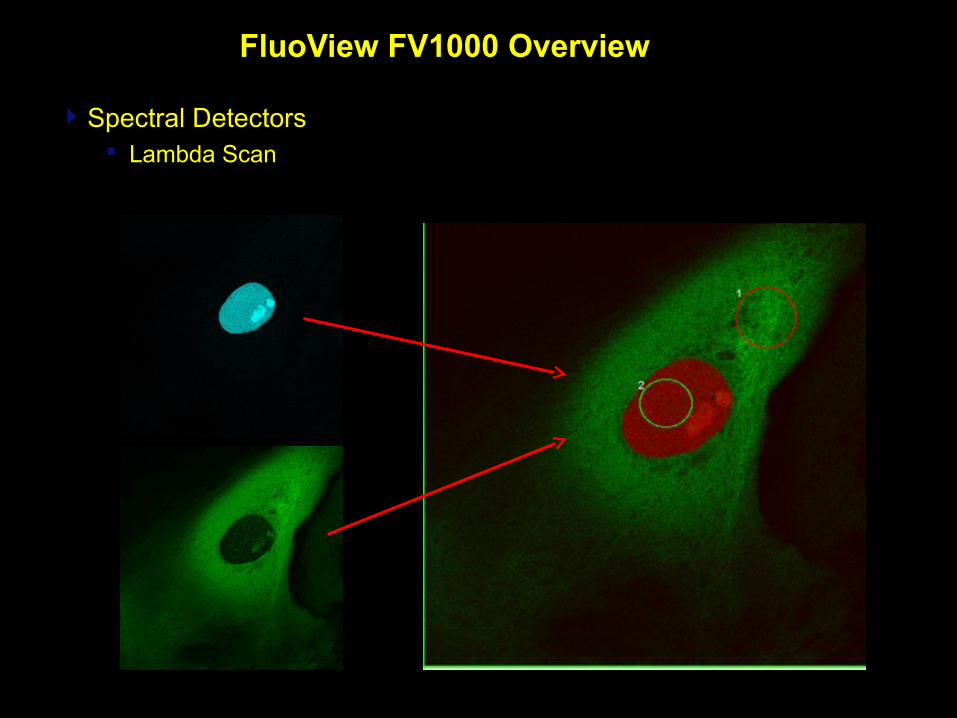
Spectral Detectors Lambda Scan
XYλ ScanExcitation 458nmDetection 480nm-660nm2nm Steps
Emission Spectrals
0
50
100
150
200
250
475
486
497
508
519
530
541
552
563
574
585
596
607
618
629
640
651
662
673
A B Detected signal (=A+B)
FluoView FV1000 Overview
Spectral Detectors Lambda Scan
FluoView FV1000 Overview
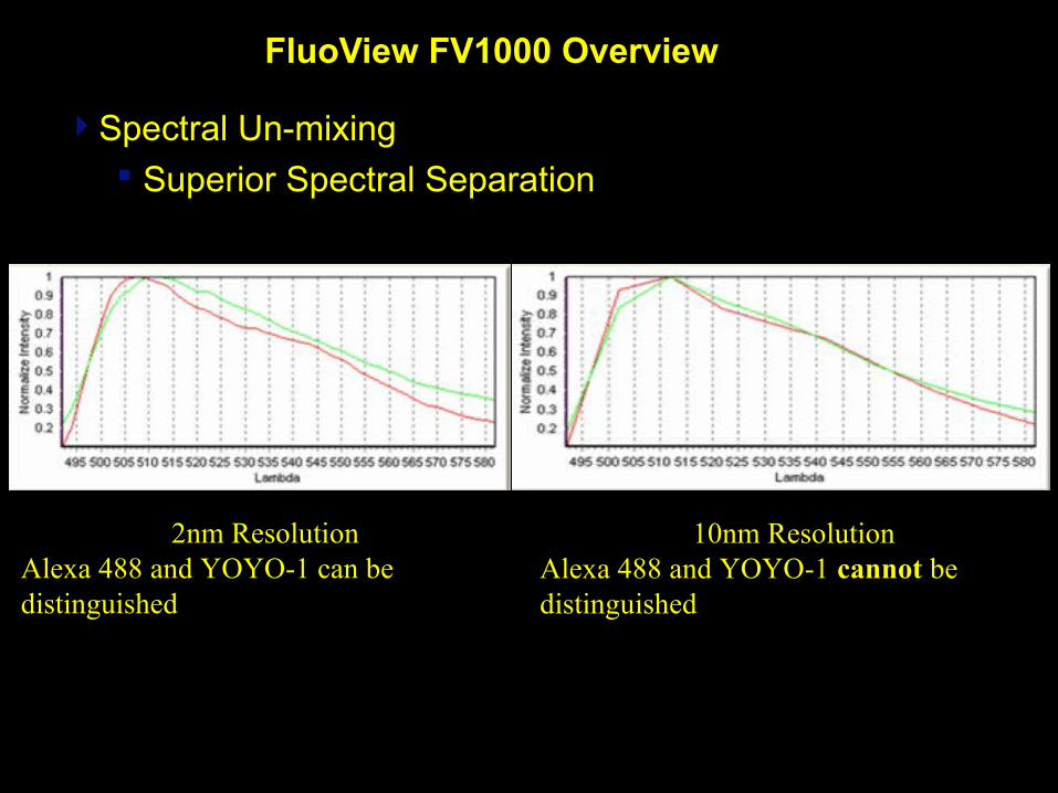
Spectral Un-mixing Superior Spectral Separation
2nm ResolutionAlexa 488 and YOYO-1 can be distinguished
10nm ResolutionAlexa 488 and YOYO-1 cannot be distinguished

Brainbow fish
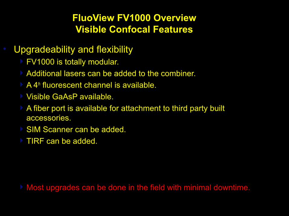
FluoView FV1000 OverviewVisible Confocal Features
• Upgradeability and flexibilityFV1000 is totally modular. Additional lasers can be added to the combiner. A 4th fluorescent channel is available. Visible GaAsP available.A fiber port is available for attachment to third party built
accessories.SIM Scanner can be added. TIRF can be added.
Most upgrades can be done in the field with minimal downtime.
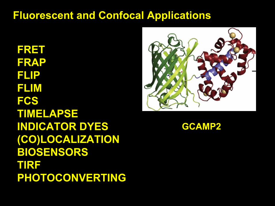
Fluorescent and Confocal Applications
FRETFRAPFLIPFLIMFCSTIMELAPSEINDICATOR DYES(CO)LOCALIZATIONBIOSENSORSTIRFPHOTOCONVERTING
GCAMP2

COMBINING RATIOMETRIC INDICATOR IMAGING WITH FRET IMAGING
INTERPLAY BETWEEN CALCIUM AND cAMP
FURA-2 AM AND EPAC1-CAMPS
Roe et al.

KAEDE - PHOTOCONVERTING FLUORESCENT PROTEIN

KAEDE - PHOTOCONVERTING FLUORESCENT PROTEIN
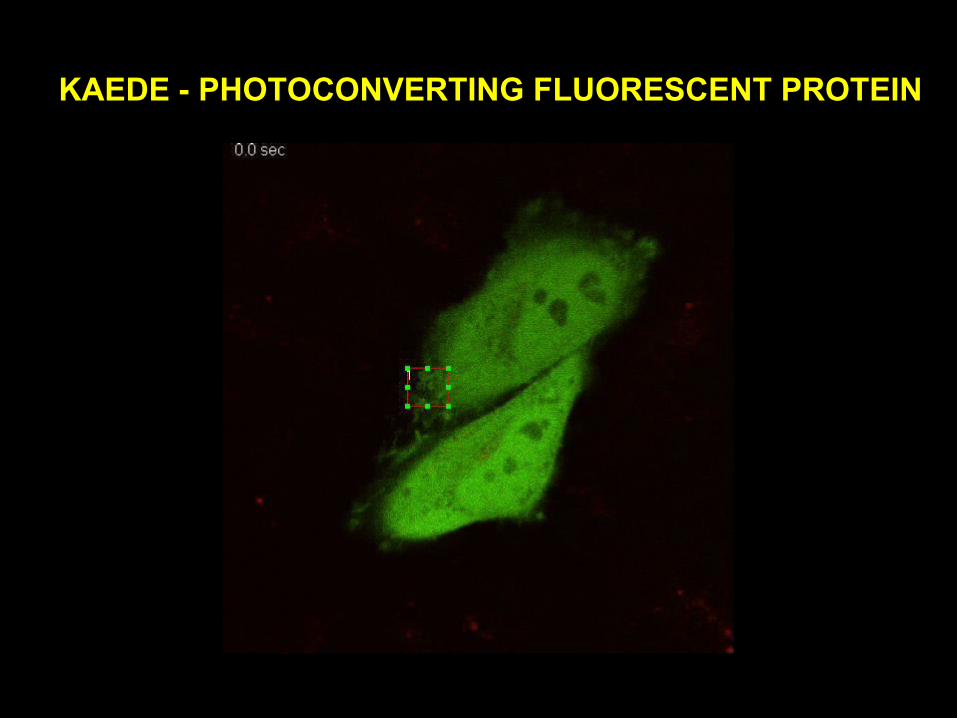
KAEDE - PHOTOCONVERTING FLUORESCENT PROTEIN
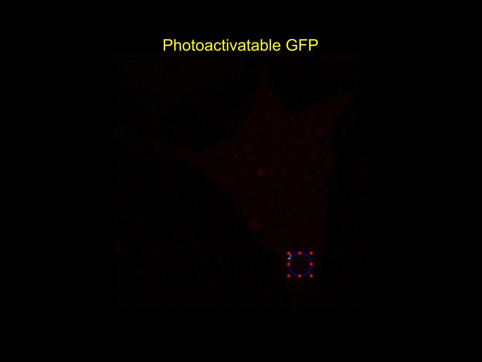
Photoactivatable GFP

Multiphoton Imaging
Mouse Cerebral Cortex Image provided by: Kei Eto, Hiroyuki Inada, Yusuke Takatsuru, Hiroaki Waki, Tomomi Nemoto, and Junichi Nabekura, National Institute for Physiological Sciences, National Institutes
of Natural Sciences, Japan
Visible light confocal Multiphoton excitation
Layer V neurons800m deep
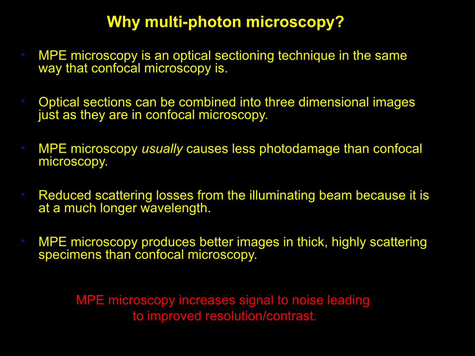
Why multi-photon microscopy?
• MPE microscopy is an optical sectioning technique in the same way that confocal microscopy is.
• Optical sections can be combined into three dimensional images just as they are in confocal microscopy.
• MPE microscopy usually causes less photodamage than confocal microscopy.
• Reduced scattering losses from the illuminating beam because it is at a much longer wavelength.
• MPE microscopy produces better images in thick, highly scattering specimens than confocal microscopy.
MPE microscopy increases signal to noise leading to improved resolution/contrast.

MPE Imaging
MOUSE TRANSGENICEYE EXPRESSINGtdTOMATO
960nm
Z-series
Optical sectioning
DEEP
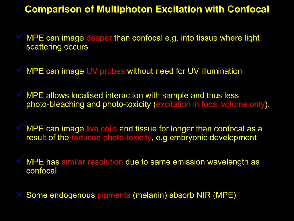
Comparison of Multiphoton Excitation with Confocal
MPE can image deeper than confocal e.g. into tissue where light scattering occurs
MPE can image UV probes without need for UV illumination
MPE allows localised interaction with sample and thus less photo-bleaching and photo-toxicity (excitation in focal volume only).
MPE can image live cells and tissue for longer than confocal as a result of the reduced photo-toxicity, e.g embryonic development
MPE has similar resolution due to same emission wavelength as confocal
Some endogenous pigments (melanin) absorb NIR (MPE)

Transgenic mouse eyes expressing tdTomato