multi-level voltage sourced conversion by voltage reinjection at six times the fundamental frequency
TRANSCRIPT
Multi-level voltage sourced conversion by voltage reinjection at six times the fundamental frequency
Y.H. Liu, J. Arrillaga and N.R. Watson
Abstract: The proposed multilevel voltage-sourced converter is based on the reinjection of DC voltage pulses at six times the fundamental frequency. The extra (xinjection) components required are justified by a substantial reduction in the capacitor size. It is shown that the resulting voltage and current harmonics are well within the present standards without the assistance of pulsewidth modulation. Theoretical waveforms are verified by computer simulation using the PSCADiEMTDC package.
1 Introduction
Three main basic options have been considered to reduce the harmonic content of voltage source converters, i.e. multipulse conversion, multilevel conversion and pulse- width modulation. The multipulse configuration consists of several six-pulse converter units in either series or parallel on the DC side. These units are phase-shifted with respect to each other by the transformer connection. Pulse numbers as high as 48 have already been used in demonstration models [I], however, pulse numbers higher than 12 require complicated and costly transformer winding connections.
The best known multi-level configuration is probably the so-called neutral-point clamped converter (NPCC) [2], where the DC capacitor is split into several stages, each stage designed for the same fraction of the total DC bus voltage. Through a switch assembly consisting of power semiconductor switches (diode and either GTOs or ICBTs) the AC output can be placed at any of these capacitor voltage levels, thereby generating step waveforms closer to the sine wave. This approach requires a large number of switches and a complex control system but uses a simple transformer arrangement. Its advantages over the tradi- tional two-level converter are somewhat cancelled by the need to balance the capacitor voltage levels and unequal utilisation of the switching devices. An extension of the NPCC, the diode clamped multilevel converter, has been studied for potential application to power systems exten- sively [3, 41, and different applications have been reported.
An alternative multilevel configuration is the flying capacitor converter. It uses a combination of switches and capacitors with a better-defined voltage across any blocking switch. Better capacitor balance is achieved at the expense of a high number of capacitors.
The multipulse and most multilevel arrangements use fundamental frequency modulation because each switch in the converter turns on and off only once per cycle to reduce the switching losses.
There is no need for extra circuitry and devices in the case of pulse-width modulation (PWM), a concept extensively
Q IEE, 2W2 IEE Proceedings online no. 20020179 Dol: IO. 1049/iwpa:20020179 Paper first reccivrd 18th July 2001 and in revised foim 141h January 2W2 The authors BE with the Department of Elect%d and Elenronic En@neering. Uniwruly of Canterbury, New 7xaland
IEE Proc.-Ekwr POHW AppL Vu/. 149. No. 3, May 2002
used by the power conversion industry at low and medium power levels. While the capacity of the switching devices has increased considerably, large rating applications still require the use of series and parallel combinations of devices or converter units and each of these configurations increases the switching losses. Thus the switching frequency is generally kept relatively low and this in turn reduces the effectiveness of PWM to suppress harmonics.
A ripple reinjection concept [5] developed for line- commutated converters has been shown to increase the pulse number of the conventional converter units and thus reduce harmonic distortion. Using a similar concept, this paper describes a new scheme based on the reinjection of direct voltage pulses at six times the fundamental frequency to reduce the harmonic content produced by voltage-source converters.
2 scheme
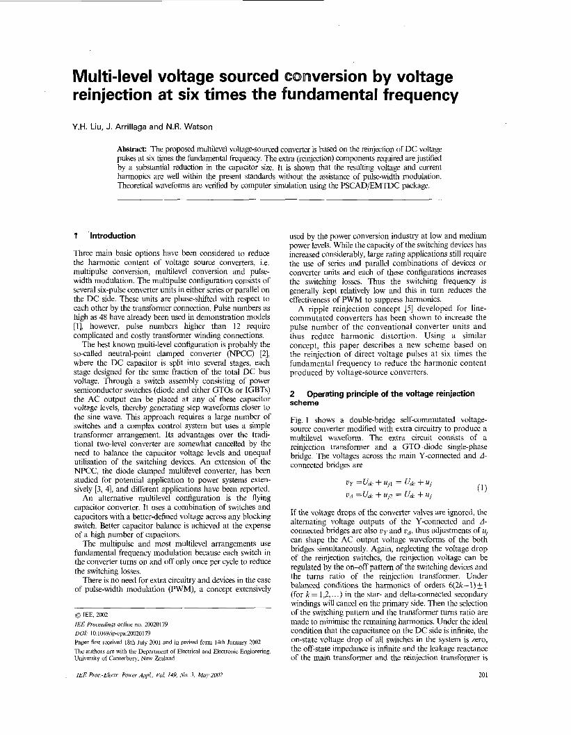
Fig. 1 shows a double-bridge self-commutated voltage- source converter modified with extra circuitry to produce a multilevel waveform. The extra circuit consists of a reinjection transformer and a GTO-diode single-phase bridge. The voltages across the main Y-connected and d- connected bridges are
Operating principle of the voltage reinjection
0) u y =u& + UjI = u* 4- u,
U A =u& + uj> = u* + u j
If the voltage drops of the converter valves are ignored, the alternating voltage outputs of the Y-connected and A - connected bridges are also t i y and ud, thus adjustments of u, can shape the AC output voltage waveforms of the both bridges simultaneously. Again, neglecting the voltage drop of the reinjection switches, the reinjection voltage can be regulated by the on-aff pattern of the switching devices and the turns ratio of the reinjection transformer. Under balanced conditions the harmonics of orders 6(2&1)+_ 1 (for k = I ,2 , . . .) in the star- and dehd-connected secondary windings will cancel on the primary side. Then the selection of the switching pattern and the transformer turns ratio are made to minimise the remaining harmonics. Under the ideal condition that the capacitance on the DC side is infinite, the on-state voltage drop of all switches in the system is zero, the off-state impedance is infinite and the leakage reactance of the main transformer and the reinjection transformer is
201
- ia VYA
Fig. 1 36-pulse self-cummutated tio[/aye-.owce conwrter
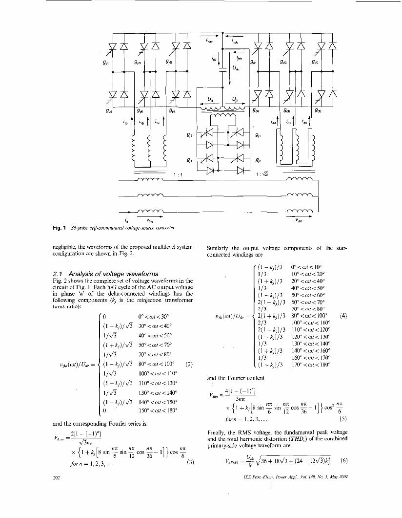
negligible, the waveforms of the proposed multilevel system configuration are shown in Fig. 2.
2.1 Analysis of voltage waveforms Fig. 2 shows the complete E t of voltage waveforms in the circuit of Fig. 1. Each ha!r^cycle of the AC output voltage in phase 'a' of the delta-connected windings has the following components (4 is the reinjechon transformer
0" < W / < 30"
30" <ut < 40"
40" < u t i 50"
500 <WI< 70" 70"<o t i80"
80"<ot<100" (2)
100" < Wf < I IO"
1 10" <ul< 130"
130" <cut< 140" 140"<wt<150" 150"<ut<180"
and the corresponding Fourier series is:
2[1 - (-l)"] &nn
VAm
nn . nn nn nn x { 1 + k j [8 sin sin E cos 36 - 1
forn= l , 2 , 3 , . . . (3)
Similarly the output voltage components of the star- connected windings are
(l-k,)/3 O"<wt<10"
(1 + k,)/3 20"<wt<40" 113 40" < u t < 50" ( I -k,)/3 50"<ot<60" 2(1 -k l ) /3 60"<wI<70" 213 70" < 01 < 80" 2(1 + k , ) / 3 8 0 " < ~ f < 1 0 0 " (4)
2(1 -kl)/3 ll0"<wt<l20"
1 / 3 130" < cot i 140" (1 +k,)/3 I W < w t i 1 6 0 " ' 1 3 160" i OI < 170" (1 - k , ) / 3 170"<wt<180"
113 10" <wt<20"
213 100"<or< 1 IO"
( I - k , ) p I ~ o ~ < w ~ < I ~ o ~
and the Fourier content
4[1 - (-1)"l 3nn V Y , =
nn . nn nn nn sin - cos - - 11 } cos2 -
12 36 6 x { 1 + kj [s sin
f o r n = l , 2 > 3 > . . . ( 5 )
Finally, the RMS voltage, the fundamental peak voltage and the total harmonic distortion (THDJ of the combined primary-side voltage waveform are
udc GAMS = - J36 + lS& + (24 - 1 2 f i ) k : ( 6 ) 9
IEE Proc.-Elrirr. Power Appl., Yo/. 149, h'o. 3, May 2002 202
1 -
-1 -
v,,(wt) =
a
-1 :E b
w V,,, sin(mut + 4 )
KO-, sin(mwt + 120" + 4 )
&:unm sin(mot - 120" + 4)
"t=l
cc
m = / m
.,=I
-1 rIIzl 0 60 120 180 240 300 360
=
-1 tIlLdA 0 60 120 180 240 300 360
- 1 -[v,,,1 cos(wr + 4 ) - Km cos(wt)] wL*
1 cos(wr ~ 120" + 4 ) - K, cos(w1 - l20.)]
WL, 1 -[KO,,, cos(w1 + 120" + 4 ) ~ v,, cos(wt + 120")l
.mL
voltage across the converter transformer is given by the
Neglecting the winding resistances the steady-state converter output currents are gven by
a " ( w t )
5 , = VYAI + GRI
H . B = !% [ I + (4 cos sin E - l)k,] (7)
The value of the reinjection transformer tums ratio that minimises the THD (8) is
7 l . x kj = I .5(7 + 4 h ) (4 cos - sin - - 1 0.6547 (9)
and THDm,,= 5.09%. Fig. 2e shows the harmonic spec- trum of the output voltage for the optimum value (kj= 0.6547) of the reinjection transformer turns ratio.
2.2 Analysis of output current waveforms If the source impedance is not significant compared with the transformer leakage Z,, the supply system can be modelled as an ideal three-phase voltage source V, and the
36 12 )
IEE Pmc.-EkI?. Power A& Yol 149, No. 3. May 2032
Equation (1 1) shows that the harmonic currents injections are determined solely by the harmonics of the converter output voltages, i.e. they are independent of their respective fundamental components of current. Thus for a specified voltage waveform. the only way to reduce the harmonic current injection is to increase the interface transformer leakage inductance.
If the converter output voltage is in phase with the power system voltage (4 = 0) and their amplitudes are related by the expression
L 1 ~ I/, = K m l / k (12)
the fundamental amplitude of the converter output current IS
L,I = V , , i / ( k w L , ) (13)
and the percentage harmonic components
The total harmonic distortion of the converter output current at the rated condition is
THD,K = 1.2476 x x ( 1 + l / k s ) ( 1 5 )
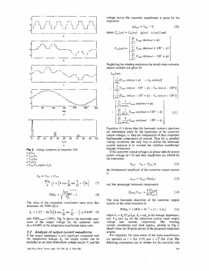
where k, = A',/( Vyd/5d, x, = wL, is the leakage impedance, and VIR and I,, are the reinjection system rated output voltage and current, respectively. The resulting current waveforms and their spectra, plotted in Fig. 3, clearly show the 36-pulse nature of the proposed reinjection scheme.
For simplicity the turns ratios of the main transformers are specified as 1 : 1 (for Y/Y) and 1 : & (for Y/d). The following expressions can be written for the converter side
203
-1 a
b
-0.21 I c
-0.21 I d
0
-0.11 I 0 60 120 180 240 300 360
deg e
spectra under specfic
current of the Y,V and YlA converter transformers:
f L ( w t ) =[ iyo(wt) ifi(cut) iyc(Wtj 1 = /:,,(at) =[i,(ot) ia(wt) i c ( w t ) ]
I,',,(wtj = i i d o p ( W t j i d b p ( W f ) i dcp (Wt j 1 (16) I I
~ - x ~ L , , ( w r ) =- [ iA(~ t ) ig (w t ) iC(wt j ] JI
and the line current vector becomes
/:d(wt) =(idn(wt) i d b ( W t ) i d c ( w t j ] = ~ L ~ ( w t ~ 30") = [ i ~ ( w t - 30") i B ( W f - 30") ic(w/ - 30")]
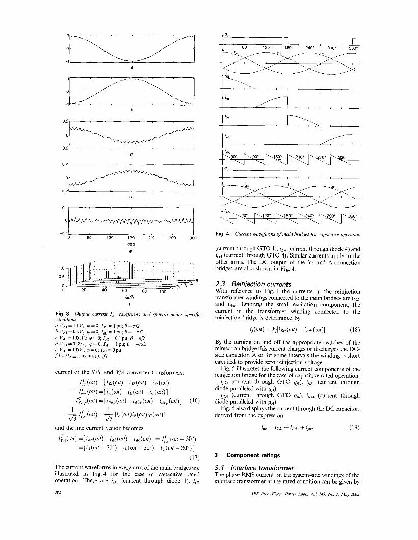
(17) The current waveforms in every arm of the main bridges are illustrated in Fig. 4 for the case of capacitive rated operation. These are iD1 (current through diode I), icl
204
I , ; . . ,
I** h 0 s 20" W P w4 0 ' i \ a O O * h 6 0 * u u '-4 u u u -.
Fig. 4 Ciarenr ii:a~efu1efu1711s of main bridyes fur capciriw upwarion
(current through GTO I), iu4 (current through diode 4) and ic4 (current through GTO 4). Similar currents apply to the other arms. The DC output of the Y- and A-connection bridges are also shown in Fig. 4.
2.3 Reinjection currents With reference to Fig. 1 the currents in the reinjection transformer windings connected to the main bridges are i,.,,, and Ignoring the small excitation component, the current in the transformer winding connected to the reinjection bridge is determined by
ij(wt) = k j [ i yk (u t ) ~ idk(wr)] (18)
By the tinning on and off the appropriate switches of the reinjection bridge this current charges or discharges the DC- side capacitor. Also for some intervals the winding is short circuited to provide zero reinjection voltage.
Fig. 5 illustrates the following current components of the reinjection bridge for the c a s of capacitive rated operation:
G G ~ (current through GTO gJ, GDI (current through diode paralleled with gj l )
iic4 (current through GTO gj4), Gm (current through diode paralleled with q*)
Fig. 5 also displays the current through the DC capacitor, derived from the expression
= i y k +id,+, + i j e (19)
3 Component ratings
3. I Interface transformer The phase RMS current on the system-side windings of the interface transformer at the rated condition can be given by
IEE P'ruc.-Elwrr. Power &I., Val. 149. No. 3. hloy ZW2
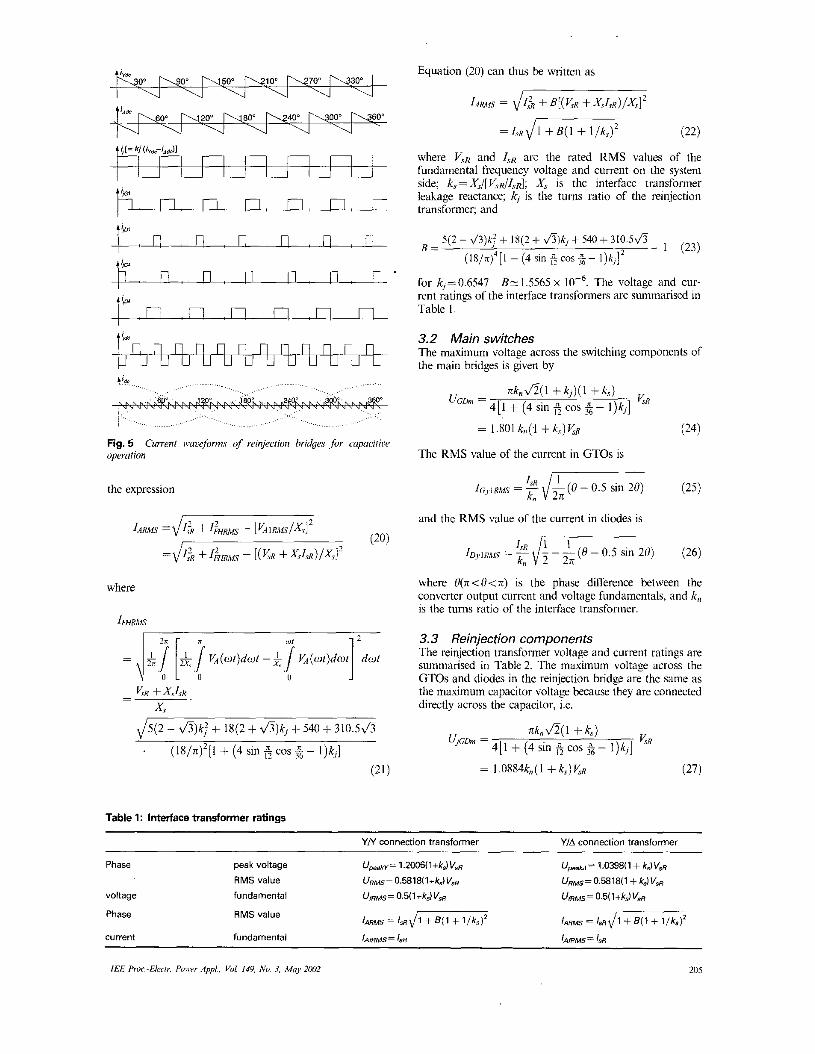
Fig. 5 operution
Current wacefurms oj reinjection bridges for capacititie
the expression
where
$(2 - &)kj + lX(2 + &)kj + 540 + 310.5&
(IS/n)*[l + (4 sin 6 cos 5 - l ) k j ] .
Table 1: Interface eansformer ratings
Equation (20) can thus be written as
1ARM.7 = d1$ + B [ ( K R +XsIsd/xs]*
= I.sR Jm ( 2 2 )
where !+< and IsR are the rated RMS values of the fundamental frequency voltage and current on the system side; k, = X,/[ VvR/ZTd; X, is the interface transformer leakage reactance; ki is the turns ratio of the reinjection transformer; and
for +0.6547 B E 1.5565 x The voltage and cur- rent ratings of the interface transformers are summarised in Table I
3.2 Main switches The maximum voltage across the switching components of the main bridges is given by
nk,,&(l + k , ) ( l + k , ) v, uGDn' = 4[1 + (4 sin fi cos 4 - I)k,]
= 1.801 k,# + k,) 5.R (24)
The RMS value of the current in GTOs is
(25) ICJi~,,s = - IsR d s ( H I - 0.5 sin 20) kn
and the RMS value of the current in diodes is
where O(n<H<n) is the phase difference between the converter output current and voltage fundamentals, and k,, is the turns ratio of the interface transformer.
3.3 Reinjection components The reinjection transformer voltage and current ratings are summarised in Table 2. The maximum voltage across the GTOs and diodes in the reinjection bridge are the same as the maximum capacitor vobage because they are connected directly across the capacitor, i.e.
YN connection transformer YJA connection transformer
Phase
voltage
Phase
current
IEE Pro?.-Elcclr. Poiwr Appl., Yo!. 149. No. 3, M q ZWZ 205
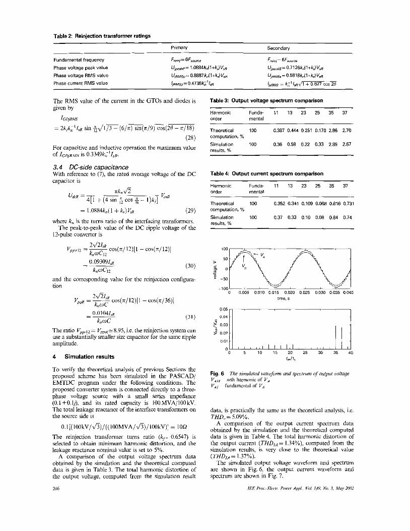
Table 2 Reinjection transformer ratings
Primav Secondaty
Fundamental frequency Fm;n;= 6Fs0,, Fmrnj= 6F30me
Phase voltage peak value
Phase voltage RMS value
Phase current RMS value
Ujwa~p= 1 .0884kn(l+k,) Vs,q
U ~ R R M S ~ = 0.8887kJ 1 +kJ V s ~ l j ~ ~ s , , = O.4738k;'l3~
Ujmaks = 0.7 126kJ 1 +k,) V,n
UinM~r = 0.5818kn(1 +kJ V,
L R M ~ = k i ' l aJ1 + 0.827 cos 28
The RMS value of the current in the GTOs and diodes is given by
fGDjRMS
= 2kik;'IsR sin $J1/3 - ( 6 / n ) sin(n19) cos(20 - n/lS)
(28) For capacitive and inductive operation the maximum value of IGWR,ws is O.3349k;'IsR.
3.4 DC-side capacitance With reference to (7), the rated average voltage of the DC capacitor is
nkn& 4 [ 1 + (4 sin 4 cos $- I ) k j ] u&R = VcnR
= 1 .0884k, ( 1 + k,) K.q (29)
where k. is the turns ratio of the interfacing transformers. The peak-to-peak value of the DC ripple voltage of the
12-pulse converter is
Vppr12 = - 2Jz1sR cos(n/l2)[1 - cos(n/12)] knuCi2
and the corresponding value for the reinjection confiyra- tion
v,, = k,oc 2Jz" cos(n/l2)[l - cos(rr/36)]
The ratio VpPrl2= V,,,,,-8.95, i.e. the reinjection system can use a substantially smaller size capacitor for the same ripple amplitude.
4 Simulation results
To verify the theoretical analysis of previous Sections the proposed scheme has been simulated in the PASCAD/ EMTDC program under the following conditions. The proposed converter system is connected directly to a three- phase voltage source with a small series impedance (0.1 +O.lj), and its rated capacity is lOOMVA/lOOkV. The total leakage reactance of the interface transformers on the source side is
0.1 [( lOOkV/~)/((lOOMVA/~)/1OOkV)] = 10Q
The reinjection transformer turns ratio (k,=0.6547) is selected to obtain minimum harmonic distortion, and the leakage reactance nominal value is set to 5%.
A comparison of the output voltage spectrum data obtained by the simulation and the theoretical computed data is given in Table 3. The total harmonic distortion of the output voltage, computed from the simulation result
206
Table 3: Output voltage spectrum comparison
Harmonic Funda- 11 13 23 25 35 37 order mental
~~
Theoretical 100 0.387 0.444 0.251 0.170 2.86 2.70 computation, %
Simulation 100 0.36 0.58 0.22 0.33 2.89 2.67 reslllf.~ %"
Table 4 Output current spectrum comparison
Harmonic Funda- 11 13 23 25 35 37 order mental
Theoretical 100 0.352 0.341 0.109 0.068 0.816 0.731 computation, %
Simulation 100 0.37 0.33 0.10 0.08 0.84 0.14 results, %
time, s
9 0.02 0.01
' 0 5 10 15 20 25 30 35 40
fmlf,
The simulured wauefii,rm und spectrum of output uolrage Fig. 6 VA,w mth harmonic of V, V,, fundamcntal of V .
data, is practically the same as the theoretical analysis, i.e. THD..= 5.09%.
A comparison of the output current spectrum data obtained by the simulation and the theoretical computed data is given in Table 4 . The total harmonic distortion of the output current (THDIA= 1.34%), computed from the simulation results, is very close to the theoretical value (THDJ,, = 1.37%).
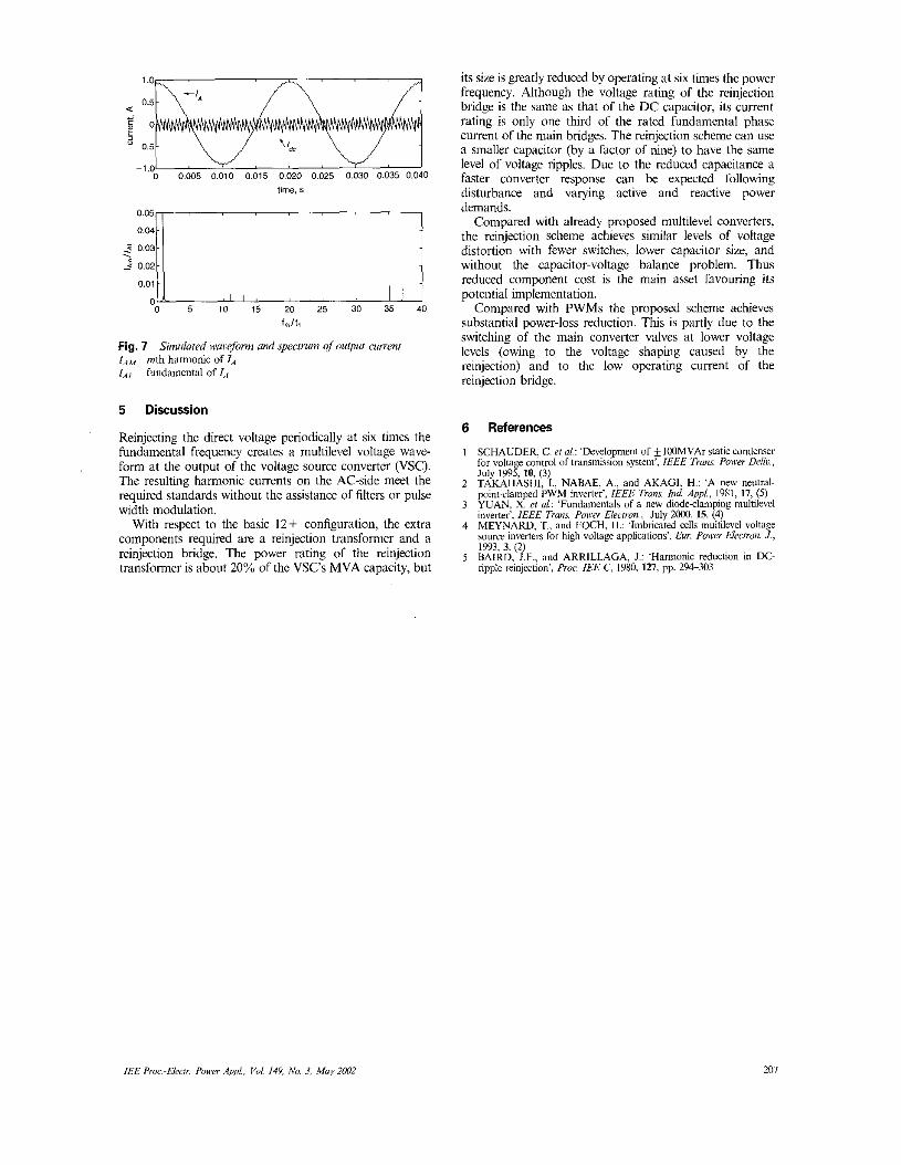
The Simulated output voltage waveform and spectrum are shown in Fig. 6, the output current waveform and spectrum are shown in Fig. 7 .
IEE Proc.-Ekrir. Poilrr Appl.. Voi 149, I\'o. 3, May 2002
0 0.005 0,010 0.015 0.020 0.025 0.030 0.035 0.040 0 0.005 0,010 0.015 0.020 0.025 0.030 0.035 0.040 lime. s <::r\ i 0.02
0.01
0 0 5 10 15 20 25 30 35 40
f,/t,
Fig. 7 laM mth harmonic of la lAr fundamental of la
Simulated wuoeform and specrrwn o/oulput amen1
5 Discussion
Reinjecting the direct voltage periodically at six times the fundamental frequency creates a multilevel voltage wave- form at the output of the voltage source converter (VSC). The resulting harmonic currents on the AC-side meet the required standards without the assistance of filters or pulse width modulation.
With respect to the basic 12+ configuration, the extra components required are a reinjection transformer and a reinjection bridge. The power rating of the reinjection transformer is about 20% of the VSC's MVA capacity, hut
its size is greatly reduced by operating at six times the power frequency. Although the voltage rating of the reinjection bridge is the same as that of the DC capacitor, its current rating is only one third of the rated fundamental phase current of the main bridges. The reinjection scheme can use a smaller capacitor (by a factor of nine) to have the same level of voltage ripples. Due to the reduced capacitance a faster converter response can be expected following disturbance and varying active and reactive power demands.
Compared with already proposed multilevel converters, the reinjection scheme achieves similar levels of voltage distortion with fewer switches, lower capacitor size, and without the capacitor-voltage balance problem. Thus reduced component cost is the main asset favouring its potential implementation.
Compared with PWMs the proposed scheme achieves substantial power-loss reduction. This is partly due to the switching of the main converter valves at lower voltage levels (owing to the voltage shaping caused by the reinjection) and to the low operating current of the reinjection bridge.
6 References
1 SCHAUDER. C. et ai: 'Development of + l00MVAr Static condenser for voltage control of transmission system', IEEE Twm. Power Delic., Julv 1995. 10, (3)
2 TAKAHASHI. 1.. NABAE, A,, and AKAGI, H.: 'A new neutral- point-clamped PWM invelter', IEEE Trans. h d Appl.. 1981, 17, (5)
3 YUAN, X. el "1.: 'Fundamentals of a new diodeslamping multilevel inverter', IEEE Trans. Power Elemon., July ?OOO. 15. 9
4 MEYNARD, T.. and FOCH, H.: 'Imbricated cells multilevel voltage soure inverten for high voltage applications'. Eur. Power Electron. J., 1993, 3. (2) BAIRD, J.F., and ARRILLAGA. I.: 'Harmonic reduction in DC- "pple reinjection', Proe IEE C. 1980, 127, pp. 294-303
5
/€E Proc.-€lelr Power AppL. Voi 149, No. 3, M q 2092 201