multi-layered security in the internet of the things
TRANSCRIPT

Univers
ity of
Cap
e Tow
n
Multi-Layered Security in theInternet of the Things
Lutando Ngqakaza
A Thesis presented for the degree of
Masters of Science
ISAT Laboratory
Department of Computer Science
University of Cape Town
South Africa
August 2014

The copyright of this thesis vests in the author. No quotation from it or information derived from it is to be published without full acknowledgement of the source. The thesis is to be used for private study or non-commercial research purposes only.
Published by the University of Cape Town (UCT) in terms of the non-exclusive license granted to UCT by the author.
Univers
ity of
Cap
e Tow
n

Dedicated toMy family, friends, and friend of over 7 years, Tamzon Jacobs thanks for the
support, love, and patience.
Multi-Layered Security In the Internet of the
Things
Lutando Ngqakaza
Submitted for the degree of Masters of Science
August 2014
Abstract
It is well discussed and understood that there is still a need for suitable security
for the Internet of Things. It is however still not clear how existing or emerging
security paradigms can be effectively applied to a network of constrained nodes
in a lossy communications environment. This thesis provides a survey into what
routing protocols can be used with network security in mind. What will also be
discussed, is an implementation, that in conjunction which a robust routing proto-
col, can provide security for a network of constrained devices with a certain level of
confidence. The implementation and design involves including communications en-
cryption and centralized non-cryptographic methods for securing the network. This
thesis basically explores the use of multiple security mechanisms in an Internet of
Things environment by using Contiki OS as the platform of choice for simulations
and testing.

Declaration
The work in this thesis is based on research carried out at the ISAT Laboratory,
the Department of Computer Sciences, The University of Cape Town. No part
of this thesis has been submitted elsewhere for any other degree or qualification
and it is all my own work unless referenced to the contrary in the text. I hereby
declare that this written work I have submitted is original work which I alone have
authored and which is written in my own words. With the signature I declare that
I have being informed regarding normal academic citation rules and I conform to
citation conventions customary to the sciences. This written work may be tested
electronically for plagiarism.
Lutando Ngqakaza Date
Copyright c© 2014 by Lutando Ngqakaza.
“The copyright of this thesis rests with the author. No quotations from it should be
published without the author’s prior written consent and information derived from
it should be acknowledged”.
iv

Acknowledgements
Dr Antoine Bagula my supervisor who helped me pave my way in the writing of the
thesis National Research Fund for helping me out with the funding of my studies.
My parents, to my mom who encouraged me to continue with my studies and to
my father who gave me strength and support to do my masters as comfortably
as possible. To my best friend Tamzon for being there for me and supporting me
throughout all of this hard work. You gave me strength and surrounded me with
your support for as long as I could remember.
v

Contents
Abstract iii
Declaration iv
Acknowledgements v
1 Introduction 1
1.1 Motivation . . . . . . . . . . . . . . . . . . . . . . . . . . . . . . . . . 2
1.2 Contribution . . . . . . . . . . . . . . . . . . . . . . . . . . . . . . . . 2
1.3 Outline . . . . . . . . . . . . . . . . . . . . . . . . . . . . . . . . . . . 3
2 Security Landscape 5
2.1 Motivation . . . . . . . . . . . . . . . . . . . . . . . . . . . . . . . . . 5
2.2 Security Concerns . . . . . . . . . . . . . . . . . . . . . . . . . . . . . 7
2.3 Confidentiality, Integrity, and Availability . . . . . . . . . . . . . . . 7
2.4 Common Attacks . . . . . . . . . . . . . . . . . . . . . . . . . . . . . 8
2.5 Suggested Guidelines . . . . . . . . . . . . . . . . . . . . . . . . . . . 10
2.5.1 Physical Security . . . . . . . . . . . . . . . . . . . . . . . . . 11
2.5.2 Link-Layer Security . . . . . . . . . . . . . . . . . . . . . . . . 12
2.5.3 FIPS-Certified Cryptographic Software . . . . . . . . . . . . . 12
2.5.4 Leverage Existing Security Standards . . . . . . . . . . . . . . 12
2.5.5 Code and Choice Optimization for Constrained Devices . . . . 13
2.6 Summary . . . . . . . . . . . . . . . . . . . . . . . . . . . . . . . . . 14
3 Design and Implementation 15
3.1 Research Design . . . . . . . . . . . . . . . . . . . . . . . . . . . . . . 15
vi
Contents vii
3.1.1 Research Questions . . . . . . . . . . . . . . . . . . . . . . . . 15
3.2 Research Design Plan . . . . . . . . . . . . . . . . . . . . . . . . . . . 17
3.2.1 Communications Protocol . . . . . . . . . . . . . . . . . . . . 17
3.2.2 Centralised Security . . . . . . . . . . . . . . . . . . . . . . . 18
3.2.3 Routing Protocol . . . . . . . . . . . . . . . . . . . . . . . . . 18
3.2.4 Layered Security . . . . . . . . . . . . . . . . . . . . . . . . . 19
4 Least Interference Beaconing Protocol 21
4.1 Introduction . . . . . . . . . . . . . . . . . . . . . . . . . . . . . . . . 21
4.1.1 Routing Over Constrained Devices . . . . . . . . . . . . . . . 22
4.1.2 Contribution And Outline . . . . . . . . . . . . . . . . . . . . 23
4.2 Least Path Interference Beaconing Protocol (LIBP) . . . . . . . . . . 23
4.2.1 Protocol description . . . . . . . . . . . . . . . . . . . . . . . 23
4.2.2 LIBP Implementation . . . . . . . . . . . . . . . . . . . . . . 24
4.2.3 LIBP Network Building Process . . . . . . . . . . . . . . . . . 24
4.2.4 LIBP Maintenance and Recovery . . . . . . . . . . . . . . . . 25
4.3 Related Routing Protocols: RPL and CTP. . . . . . . . . . . . . . . . 26
4.3.1 Collection Tree Protocol (CTP) . . . . . . . . . . . . . . . . . 26
4.3.2 Routing Protocol for LLNs (RPL) . . . . . . . . . . . . . . . . 27
4.4 Performance Evaluation . . . . . . . . . . . . . . . . . . . . . . . . . 29
4.4.1 Methodology . . . . . . . . . . . . . . . . . . . . . . . . . . . 31
4.4.2 Results and Evaluation . . . . . . . . . . . . . . . . . . . . . . 32
4.4.3 Routing Profile . . . . . . . . . . . . . . . . . . . . . . . . . . 35
4.4.4 Traffic Profile . . . . . . . . . . . . . . . . . . . . . . . . . . . 38
4.5 Analysis, and Conclusion . . . . . . . . . . . . . . . . . . . . . . . . . 39
5 Communications Cryptography 40
5.1 Introduction . . . . . . . . . . . . . . . . . . . . . . . . . . . . . . . . 40
5.1.1 IEEE 802.15.4 Overview and Security . . . . . . . . . . . . . . 40
5.1.2 Keying Modes . . . . . . . . . . . . . . . . . . . . . . . . . . . 43
5.1.3 CIA in IEEE 802.15.4 . . . . . . . . . . . . . . . . . . . . . . 44
5.1.4 IEEE 802.15.4 Drawbacks . . . . . . . . . . . . . . . . . . . . 45
August 25, 2014

Contents viii
5.2 Performance Evaluation . . . . . . . . . . . . . . . . . . . . . . . . . 49
5.2.1 Methodology . . . . . . . . . . . . . . . . . . . . . . . . . . . 50
5.2.2 Results, and Evaluation . . . . . . . . . . . . . . . . . . . . . 51
5.3 Analysis, and Conclusion . . . . . . . . . . . . . . . . . . . . . . . . . 54
6 Centralized Security 55
6.1 Introduction . . . . . . . . . . . . . . . . . . . . . . . . . . . . . . . . 55
6.2 Contribution . . . . . . . . . . . . . . . . . . . . . . . . . . . . . . . . 56
6.3 Related Work . . . . . . . . . . . . . . . . . . . . . . . . . . . . . . . 56
6.4 Threat Model . . . . . . . . . . . . . . . . . . . . . . . . . . . . . . . 57
6.5 The Sinkhole Attack . . . . . . . . . . . . . . . . . . . . . . . . . . . 57
6.6 The Centralised Security Process (CSP) . . . . . . . . . . . . . . . . 58
6.6.1 CSP Implementation . . . . . . . . . . . . . . . . . . . . . . . 59
6.6.2 CSP Network Model . . . . . . . . . . . . . . . . . . . . . . . 59
6.6.3 CSP Sinkhole Detection . . . . . . . . . . . . . . . . . . . . . 60
6.6.4 CSP Sinkhole Reaction . . . . . . . . . . . . . . . . . . . . . . 62
6.7 Testing and Experiment Methodology . . . . . . . . . . . . . . . . . . 62
6.8 Results and Evaluation . . . . . . . . . . . . . . . . . . . . . . . . . . 63
6.8.1 Accuracy of Sinkhole Detection . . . . . . . . . . . . . . . . . 64
6.8.2 Speed of Sinkhole Detection and Reaction . . . . . . . . . . . 67
6.8.3 Overhead Cost of The CSP . . . . . . . . . . . . . . . . . . . 68
6.9 Analysis, and Conclusion . . . . . . . . . . . . . . . . . . . . . . . . . 69
7 Discussion 71
7.1 Threat Model . . . . . . . . . . . . . . . . . . . . . . . . . . . . . . . 71
7.2 System Configurability . . . . . . . . . . . . . . . . . . . . . . . . . . 72
7.3 Known Issues . . . . . . . . . . . . . . . . . . . . . . . . . . . . . . . 74
7.4 Future Implementations . . . . . . . . . . . . . . . . . . . . . . . . . 75
8 Conclusion 77
Appendix 84
August 25, 2014

Contents ix
A LIBP Protocol Description 84
B Least Interferance Beaconing API Documentation 87
B.1 LIBP . . . . . . . . . . . . . . . . . . . . . . . . . . . . . . . . . . . . 87
B.2 LIBP Link Metric . . . . . . . . . . . . . . . . . . . . . . . . . . . . . 88
B.3 LIBP Neighbour . . . . . . . . . . . . . . . . . . . . . . . . . . . . . . 88
August 25, 2014

Glossary
6LoWPAN IPv6 over Low power Wireless Personal Area Networks.
ACL Access Control List.
AES Advanced Encryption Standard.
CCM Counter with CBC-MAC.
CIA Confidentiality Integrity Availability.
CSP Centralised Security Process.
DES Data Encryption Standard.
DoS Denial of Service.
ETX Expected Transmissions.
FIPS Federal Information Processing Standards group.
HMAC Hash-Based Message Authentication Code.
IEEE Institute of Electrical and Eletronics Engineers.
IETF Internet Engineering Task Force.
IoT The Internet of the Things.
IP Internet Protocol.
IPSec Internet Protocol Security.
x

Glossary xi
IPv6 Internet Protocol version 6.
LIBP Least Interference Beaconing Protocol.
LLN Low-Powered and Lossy Network.
MAC Message Authentication Code.
MAC (2) Medium Access Control.
OF Objective Function.
OS Operating System.
RFC Request For Comments.
RFID Radio-Frequency Identification.
RPL Routing Protocol for LLNs.
SSH Secure Shell.
UDP User Datagram Protocol.
USN Ubiquitous Sensor Network.
WSN Wireless Sensor Network.
August 25, 2014

List of Figures
3.1 Layering of Security Functions . . . . . . . . . . . . . . . . . . . . . . 19
4.1 Average Power Consumption . . . . . . . . . . . . . . . . . . . . . . . 32
4.2 Radio Duty . . . . . . . . . . . . . . . . . . . . . . . . . . . . . . . . 33
4.3 Radio duty for the sink nodes . . . . . . . . . . . . . . . . . . . . . . 33
4.4 Scalability for the average power consumption . . . . . . . . . . . . . 34
4.5 Contention . . . . . . . . . . . . . . . . . . . . . . . . . . . . . . . . . 35
4.6 Average Path Length . . . . . . . . . . . . . . . . . . . . . . . . . . . 36
4.7 Time taken for node to recover from network failure . . . . . . . . . . 36
4.8 Time taken for a new node to join the network . . . . . . . . . . . . . 37
4.9 Control Packets Sent . . . . . . . . . . . . . . . . . . . . . . . . . . . 38
5.1 IEEE 802.15.4 Packet Description . . . . . . . . . . . . . . . . . . . . 41
5.2 Power used by each security mode . . . . . . . . . . . . . . . . . . . . 52
5.3 Cryptographic operations per minute . . . . . . . . . . . . . . . . . . 53
6.1 Illustration of a possible sink-hole . . . . . . . . . . . . . . . . . . . . 58
6.2 (a) in-memory model (b) live network topology . . . . . . . . . . . . 60
6.3 BFS Algorithm for Sinkhole Detection . . . . . . . . . . . . . . . . . 61
6.4 Sinkhole Detection Visualised . . . . . . . . . . . . . . . . . . . . . . 61
6.5 The topology size vs success rate . . . . . . . . . . . . . . . . . . . . 64
6.6 The topology size vs false-positive rate . . . . . . . . . . . . . . . . . 65
6.7 The topology size vs false negative rate . . . . . . . . . . . . . . . . . 65
6.8 The topology size vs packet drop rate . . . . . . . . . . . . . . . . . . 66
6.9 Node height vs detection speed . . . . . . . . . . . . . . . . . . . . . 67
xii

List of Figures xiii
6.10 Node height vs reaction speed . . . . . . . . . . . . . . . . . . . . . . 67
6.11 Node height vs problem resolution speed . . . . . . . . . . . . . . . . 68
7.1 Linking two WSN groups to a gateway via a backbone network . . . . 74
A.1 How LIBP works and how a node accepts a new parent . . . . . . . . 85
A.2 How LIBP works and how a node rejects an old parent . . . . . . . . 86
August 25, 2014

List of Tables
2.1 Cipher Choices . . . . . . . . . . . . . . . . . . . . . . . . . . . . . . 13
4.1 Simulation Setup . . . . . . . . . . . . . . . . . . . . . . . . . . . . . 31
4.2 Power Distribution . . . . . . . . . . . . . . . . . . . . . . . . . . . . 34
4.3 Successful Transmission Rate . . . . . . . . . . . . . . . . . . . . . . 38
5.1 802.15.4 Security Modes . . . . . . . . . . . . . . . . . . . . . . . . . 42
5.2 Delay Performance of IEEE 802.15.4 MAC layer . . . . . . . . . . . . 51
5.3 Throughput Performance of the IEEE 802.15.4 MAC layer . . . . . . 51
5.4 Energy penalty per security mode . . . . . . . . . . . . . . . . . . . . 54
6.1 Data Required by the CSP . . . . . . . . . . . . . . . . . . . . . . . . 59
6.2 Parameters for experiment . . . . . . . . . . . . . . . . . . . . . . . . 63
6.3 Average Power Consumption (mW) . . . . . . . . . . . . . . . . . . . 68
6.4 Gateway Power Consumption (mW) . . . . . . . . . . . . . . . . . . 69
6.5 Energy Usage of Sinkhole (mW) . . . . . . . . . . . . . . . . . . . . . 69
7.1 Data Required by the CSP . . . . . . . . . . . . . . . . . . . . . . . . 72
xiv
Chapter 1
Introduction
The integration of Radio-frequency identification (RFID) devices, sensors and ac-
tuators into a ubiquitous sensor network (USN) has been identified as one of the
most promising technologies that will play an important role in the emerging In-
ternet of Things that aims to expose constrained devices to the greater world wide
web of information anywhere and any-time using anything [1]. The IoT promises
to identify and sense what is happening in our daily living environment to provide
services and that provide us with safety or convenience. Some examples of such
services or applications include efficient energy management, pollution monitoring,
vehicular traffic management, drought prediction and control, disaster prevention or
home security. All of these mentioned applications could in theory use constrained
devices in the same way that we use web services in the world wide web today in
that these constrained devices can be exposed over the world wide web. A typical
USN deployment consists of a new generation of networks where RFID readers are
integrated into sensing nodes which are networked and used as both a sensor and a
backbone or link for a communication infrastructure where the sensing devices are
used to sense what is happening in their environment while the RFID devices are
used to identify the objects in location in the environment. In such a deployment,
the data collected via the RFID and sensor devices is then fed into gateways where
the information is processed and used in making decisions that translate to effective
management. In a typical IoT environment, a conglomeration of RFID tags are
attached to objects in a sensing/localized environment where the location of these
1
1.1. Motivation 2
objects is identified using the RFID technology while the sensor devices are used to
sense and collect the environmental variables.
1.1 Motivation
From an implementation and deployment point of view, additional complexity can
arise from a networking point of view if one wants to secure a network of ubiquitous
sensor networks (USNs). Securing a network of ubiquitous sensor devices is a worth-
while endeavour since it helps guarantee the goals of the Internet of Things, the goals
of the Internet of Things is to expose constrained devices onto such as information
by these devices can be provided anywhere and any-time using anything [1].
It is important to realise that much like traditional wired networks, there is no
absolute way to go about securing them, rather a general heuristic can be applied
such that if the security is implemented correctly then the network is relatively se-
cure [2]. However in the case of ubiquitous sensor networks (USNs) the problem
arises that not all devices can be guaranteed to have similar computational power.
Another motivating factor is that the location of this research is in South Africa,
and in South Africa there are still extremely rural areas devoid of any form of network
connectivity or international network connections are sporadic and unreliable. This
research could have an effect on the way in which network planners deploy these
ubiquitous sensor networks into production. The fact that rural communities could
benefit from research like this serves as another motivation for this thesis.
1.2 Contribution
This thesis focuses on looking at how routing protocols in wireless sensor networks
(WSNs) can be further secured by adding security mechanisms on top of the pro-
tocols. At the time of writing of this master’s thesis, no implementation for for the
Least Interference Beaconing Protocol (LIBP) [3] exists on the Contiki platform,
August 25, 2014
1.3. Outline 3
this thesis will show how the LIBP works in Contiki and will compare it to the
other popular routing protocols [4, 5].
Furthermore this master’s thesis will give an in-depth analysis of the mainstream
routing protocols and will suggest a method of further securing them in their current
implementation. Most of these implementations are geared towards being friendly
in constrained environments like wireless sensor networks (WSNs). The method of
further securing these networks will be by virtue of using the gateway, or root, or
sink node as a monitoring party which oversees the networks’ well-being based on
traffic data, this node will also have the responsibility to penalise nodes which seem
to behave in a negative way in terms of the networks’ deployment goals.
Following the previous contribution, an overview of what IEEE 804.15.4 MAC layer
security provides in terms of confidentiality, integrity, and authentication will be
discussed. IEEE 804.15.4 as specified has a few shortcomings and strengths, it is
important to outline the problems with the specification and relate them to the goals
of this thesis.
The combination of using multiple security mechanisms can allow the network de-
ployer to define what sort of deployment she wants. This thesis will finally show
how the use of all of the minor contributions can be tweaked to allow for a system
that can be configured from deployment based on the use case desired. This allows
for deployments to use the required amount of security for the desired deployment
to avoid unnecessary extra overheads for features that are not required. That is the
contribution of this thesis.
1.3 Outline
This thesis will outline and introduce various constrained network routing protocols,
one of them being the Least Interference Beaconing Protocol (LIBP) [3]. Initially the
security landscape in WSNs and the IoT will be overlooked in Chapter 2. In Chapter
3, will be the Design and Implementation of the entire masters research project from
both an high level and from an experiment setup standpoint. This thesis will also
outline these various routing protocols in a survey style format in Chapter 4 along
August 25, 2014

1.3. Outline 4
with introducing a new routing protocol called LIBP. Chapter 5 will cover the basic
encryption mechanisms used to achieve data communications security. Chapter 6
will introduce a concept of using the central gateway’s computational power in a
constrained network to do some form of non-cryptographic security oversight on
the network by doing various checks on the network. Chapters 7, and 8, will cover
Discussion, and Conclusion respectively.
August 25, 2014

Chapter 2
Security Landscape
This chapter gives a overview of what the security requirements are of an IoT de-
ployment. And therefore what guidelines can be followed in order to secure such a
constrained network. Garcia-Monarch, et al. and Stammerer, et al. of the IPSO
alliance [2,6] identify potential security threats in IoT deployments and also provide
guidelines towards the prevention or protection of these security attacks.
2.1 Motivation
The adoption rate of the use of smart objects or constrained devices in various indus-
tries is on the rise. If history is any yardstick to go by, any system that implements
a networking interface should have some security. Even non-critical systems could
be hijacked in order to carry out an attack on another valuable target [2]. This has
been the case in ”normal” computing systems connected via the world wide web. It
is important to value that the role of these constrained devices is typically to col-
lect data and communicate that data in some form whenever necessary to achieve
information gathering.
some industries which would benefit by the securing of these constrained net-
works would include:
Environmental - Research based applications which may involve the moni-
5

2.1. Motivation 6
toring of wild life, birds, small animals. The monitoring of environmental status
variables, for example, chemical and biological composition of the area, or pollution
in the area. These activities are incredibly popular in the fields of the environmental
conservation sciences, or in general the life sciences.
Agriculture - In the agriculture industry, there are many applications which
are emerging as viable method to enforce sustainable farming. Irrigation systems
which take into account projected weather forecasts or soil moisture could result
in a very environmentally and economically friendly solution for individuals in the
agriculture industry.
Military - The military industry provides a wide variety of use cases for se-
cure constrained networks. The monitoring of friendly forces, field surveillance, and
attack detection are a few areas in which the military industry has purposed con-
strained networks to serve.
Medicine and Health - Remote patient monitoring and portable diagnostic
machines are been used in conjunction with constrained devices to deliver medical
services to patients in remote or rural areas [7].
Smart Cities and Homes - ”Smart Grid” electricity monitoring which helps
providers respond to electricity demands swiftly. Other smart city applications in-
clude smart traffic lights and smart public parking facilities. On the Smart Home
front, home automation and home security are the main use cases.
It is clear to see how having these systems deployed in an unsecured manner
can result in disorder, the loss of life, or the loss of finances. These critical systems
cannot be deployed without some level of security implementation on the constrained
network. It should also be noted that not all of these systems need to be secured
with the same level of scrutiny. In constrained networks the general resistance to
security arises because adding security to a constrained network adds more overhead
August 25, 2014
2.2. Security Concerns 7
in terms of raw computation, stored power usage, and radio communications.
2.2 Security Concerns
2.3 Confidentiality, Integrity, and Availability
The CIA Triad - Confidentiality, Integrity, and Availability applies to all sub
domains in computer science when it comes to information security.
Confidentiality - Refers to keeping information secret or private from un-
trusted third parties. Confidentiality is typically achieved by encryption. In a
constrained network its very deployment use case determines weather confidential-
ity is required or not. In the use case of having a sensor that reads power usage
in a household then a single reading of such a sensor is typically considered non-
confidential. However if it is the case that the sensor is reading in time stamped
values of a households’ energy usage then that data is considered confidential since
if that data reaches a malicious user, he or she can infer sleeping patterns and home
energy usage patterns in order to plan a robbery on the household.
Integrity - Refers to guaranteeing that data cannot be modified without autho-
rization. Integrity is typically achieved through Message Integrity Codes or Message
Authentication Codes, sometimes called hashes or digests. These methods allow for
a communicator to sign a message with a code that can be verified cryptographically
by a receiver of a message. In the case of constrained devices, an integrity check
may be desirable on the commands they execute. Integrity checks may also be done
on firmware to make sure that the correct firmware is running.
Authenticity is a closely related concept to integrity. Since integrity [2] refers
to checking that the data has not been tampered, authenticity refers to verifying
the source of information, whether that is an entity or a person or a device. Things
like digital certificates and signatures can provide both integrity and authentication
August 25, 2014

2.4. Common Attacks 8
in most instances. As it stands there is no standard way of doing authentication on
constrained devices and smart networks however the push is in the way of X.509v3
digital certificates.
Availability - Accounts for ensuring the information collected by the network
is available for consumption when it is needed. In order to ensure a good uptime,
not only does the firmware need to be robust and fail-proof but the constrained
network itself has to be resilient to denial-of-service (DoS) attack. A typical DoS
type attack on a constrained network is an attack that breaks the routing within
the constrained network, or it is one that overloads nodes with requests such that
legitimate requests cannot be serviced. The ROLL (Routing Over Low power and
Lossy Networks) working group within the Internet Engineering Task Force (IETF)
is working on standardizing a routing security framework for IoT deployments [5]. A
portion of that framework will be discussed in Chapter 3. These routing frameworks
will safeguard against flood attacks or attacks on the collective routing logic of the
network.
Depending on the environment and application use case. A network planner may
want to chose a combination of the CIA triad or all of them to secure the network.
2.4 Common Attacks
The Constrained RESTful Environments (CoRE) working group under the IETF has
compiled a comprehensive list of common attacks that arise in constrained networks
and Low powered and Lossy Networks (LLNs) [2].
Extraction of Security Secrets - Constrained devices are very often deployed
in remote environments or environments void of any skilled humans. Normally this
means that these devices could be physically unprotected and can be easily captured
by an attacker. An attacker can then reverse engineer the firmware on the device to
extract security keys or other credentials. The whole network may be compromised
if this happens [2].
August 25, 2014

2.4. Common Attacks 9
Device Cloning & Tampering - Given the ubiquitous nature of constrained
devices. If an attacker gets hold of a device, she could do a byte by byte copy of
an existing firmware by device capturing [2]. In essence the network could end up
with multiple devices with the same identity, or the same device could end up hav-
ing multiple identities [8]. Or the device could be captured to do other malicious
activities.
The attacks above usually require physical presence of an attacker. It is therefore
customary to consider these attacks to go beyond the scope of information commu-
nications security, these issues are mostly dealt with other solutions that normally
don’t have anything to do with the constrained devices themselves so for the focus
of this thesis we will not consider these attacks.
Nodes Reporting Bogus Data - While a reality of most constrained systems
is that they are quite prone to adverse hardware problems that may translate to bad
sensor readings or erroneous communication. No good solution yet exists for this
sort of problem however a decent anomaly detection system on the gateway/base
station could prove to be a cheap fix to this problem.
Battery Attacks - Or attacks on system lifetime are attacks that are carried
out in order to deplete a group of nodes or a particular critical node in a constrained
network. There are many ways to carry out a battery attack but generally these
attacks also affect the systems uptime which is related to how available the network
is [2].
Operating System Vulnerabilities - Many constrained devices dont use an
OS. But of those that do it is important to realise that if the OS as a platform is
not stable or secure it may cause security issues along the line.
Routing Attack - A routing attack is an attack where a node asserts to the
August 25, 2014

2.5. Suggested Guidelines 10
network and neighbouring nodes that it has a route metric or link metric that is
attractive, however is false. An example of such an attack is a Sinkhole attack, this
is where a node in the network broadcasts a link metric that would entice neigh-
bouring nodes to use it as an intermediary hop for routing. This in turn means that
neighbouring nodes would forward their packets to this node that is advertising a
false link metric. Once this is achieved that node could carry out selective forward-
ing where the node can decide which packets can be dropped or forwarded up the
routing tree towards the gateway.
Denial-of-Service Attack - This is where an attacker can continuously send
requests to be processed by a node or the gateway which in turn could hog up all
the computational resources of the gateway or critical nodes. This is a very tough
attack to guard against especially in the IoT where constrained devices usually have
a low memory budget and minimal computational power, and not to mention they
run on stored energy, or solar power in some cases [2].
Man-in-the-Middle Attack - In an unsecured network, a man-in-the-middle
(MIM) attack is possible throughout the lifetime of the network as long as it re-
mains unsecured. A man in the middle attack is an attack on the network where
a node can assume the identity or a role of a particular node and cause a break in
communication between two parties. In a secure network, a MIM attack could be
possible during the key commissioning phase of the network. This is typically when
key materials are exchanged between network entities. If the key exchange protocol
or key agreement protocol assumes that no third party is able to eavesdrop on the
exchange then a man in the middle attack is more than possible [6].
2.5 Suggested Guidelines
If we want to safeguard against the attacks above it is a requirement that we must
ensure that the CIA triad is in effect. With a few more additional security require-
August 25, 2014

2.5. Suggested Guidelines 11
ments we can ensure a reasonably robust network. depending on the constrained
devices not all of these features or goals can be met due to the wide variety of
constrained devices that span a great spectrum of computational capabilities.
Non-Repudiation - This is the notion that all transactions within the net-
work cannot be denied having happened if they happened. So for example a party
cannot deny having received a packet nor can the sender deny having sent the packet.
Data Freshness - Data freshness implies that data cannot be replayed unless
required by the communications protocol. Also in the case of keys, it ensures that
keys are fresh. This in turn removes the risk of replay attacks.
In the following sections, IPSO and CoRE have made suggestions (where they
apply) when one wants to deploy a constrained network [2, 6].
2.5.1 Physical Security
Previously in the chapter, we saw that due to the portable nature of constrained
devices, and the very nature or environment in which they are deployed, leaves these
devices exposed to physical attacks. One possible attack is called node capture, where
an attacker tries to gain control of a device through physical means typically. These
types of attacks are relatively easy on devices which are deployed without tamper
proof casing. Becher, et al. noted that countermeasures are possible against node
capture attacks, some of them being:
1. By monitoring nodes for periods, or noticing the removal of a node from the
deployment area. The network could do revocation actions against suspicious
nodes. Or the node itself may destroy its own data if it suspects a physical
attack.
2. Build additional protection around a partially vulnerable platform and main-
tain it to keep up-to-date with the newest developments in embedded systems
security and attacks.
3. Protecting the bootstrap loader password to curb unauthorised access.
August 25, 2014

2.5. Suggested Guidelines 12
2.5.2 Link-Layer Security
In constrained networks both IEEE 802.15.4 implements a sub layer of the Link-
Layer (being the MAC layer) which has rudimentary security features like AES-128
encryption and CBC-MAC. In 802.11 WPA2 should be used in conjunction with AES
encryption. For the most part 6LoWPAN is the current de facto communications
protocol for the IoT. 6LoWPAN builds upon the layers that IEEE 802.15.4 provides.
IEEE 802.15.4 at it’s link layer provides both encryption and integrity verification
which is achieved by a single pre-shared key used for symmetric cryptography. And
integrity is realised by using Message Authentication Codes (MAC) in the packets.
The main downside to this approach is that this can only provide security on a hop-
by-hob basis. Which implies each node has to be a trusted entity for the network
to be secure. As it stands, end to end security in 6LoWPAN networks is still a
researched topic.
2.5.3 FIPS-Certified Cryptographic Software
In the military, health, and government industries along with their contractors are
required to use security implementations whose cryptographic functions have been
FIPS certified by The Federal Information Processing Standards (FIPS) group at
NIST. Even in industries that do not require such a robust certification, it is con-
sidered good practice to highly consider the certified software packages [2, 6].
2.5.4 Leverage Existing Security Standards
To ensure interoperability while achieving the main goal of security, using tried and
tested security solutions can result in conforming to standards across multiple bodies
like the IETF (Internet Engineering Task Force), IEEE (Institute of Electrical and
Electronics Engineers), and the IEC (International Electro-technical Commission).
August 25, 2014
2.5. Suggested Guidelines 13
2.5.5 Code and Choice Optimization for Constrained De-
vices
It is important to realise that for some devices, due to the fact that they have a very
small computational budget, it may not be feasible to implement some solutions
or encryption algorithms. Additionally, porting code to the constrained device can
prove to be a simple activity for very capable devices but for lower budget devices
it may prove to be impossible or far less feasible. Sometimes it is a good exercise
to note which algorithms can work on which devices and also consider their energy
footprint since heavier algorithms will use up more stored power per operation.
Compatibility - In the interest of interoperability, it would suit the deployment
better in the long term if the deployment is geared towards being compatible for
every network and any device that implements any solution of the chosen protocols.
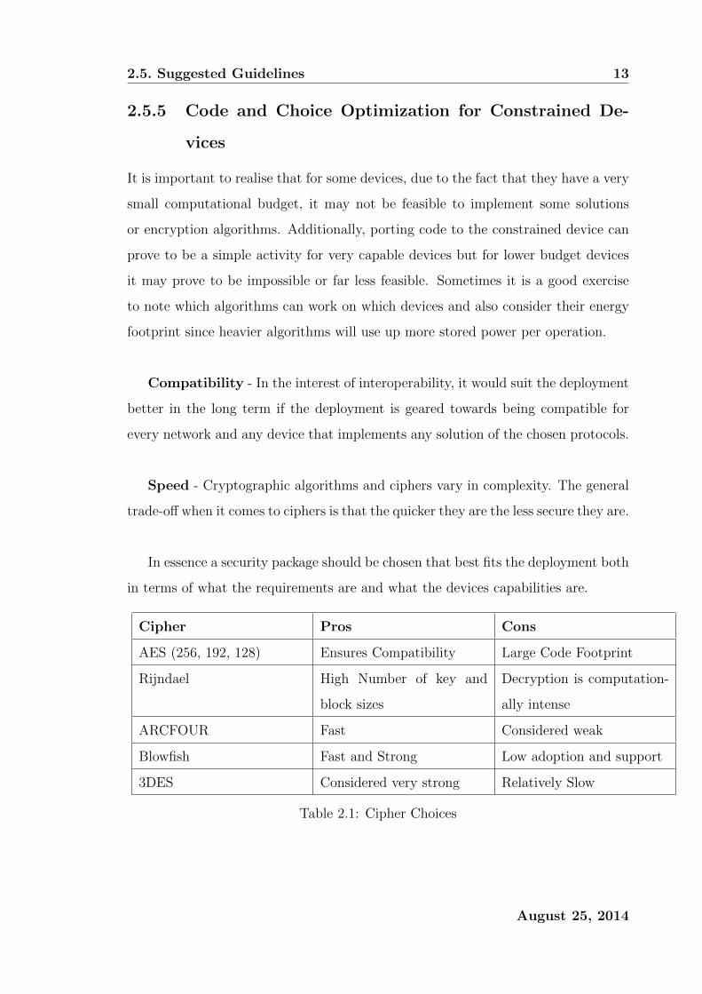
Speed - Cryptographic algorithms and ciphers vary in complexity. The general
trade-off when it comes to ciphers is that the quicker they are the less secure they are.
In essence a security package should be chosen that best fits the deployment both
in terms of what the requirements are and what the devices capabilities are.
Cipher Pros Cons
AES (256, 192, 128) Ensures Compatibility Large Code Footprint
Rijndael High Number of key and
block sizes
Decryption is computation-
ally intense
ARCFOUR Fast Considered weak
Blowfish Fast and Strong Low adoption and support
3DES Considered very strong Relatively Slow
Table 2.1: Cipher Choices
August 25, 2014

2.6. Summary 14
2.6 Summary
When it comes to securing constrained networks, the very fragmented nature of
this domain it could make it very difficult to effectively secure your network. Any
constrained network security solution should be thoroughly tested as most software
products are. It is always a good idea to test code rigorously both from a func-
tional point of view and from a security point of view, since code that does not fail
gracefully can result in a device that chokes when exceptions or unhandled memory
faults occur.
It is not yet a big priority to secure constrained networks. However as the adop-
tion rate of these types of networks increase, so does the need for secure robust
solutions for these types of networks. Many standards bodies are in debate over
standardizing various security protocols which are geared towards low powered em-
bedded devices, despite that, this area of research still shows activity.
August 25, 2014

Chapter 3
Design and Implementation
In this chapter, the way in which the research was designed and the way in which
the software was implemented will be discussed. This chapter will cover both the
high level concepts that will be discussed later on in this thesis and how they all fit
together to form a Multi-Layered protection mechanism for wireless sensor network
security.
3.1 Research Design
The research design will follow the set of questions set out in the next section. We
will look at how we can address the issue of securing a constrained network and by
doing so, formulate applicable research questions.
3.1.1 Research Questions
There are two main research questions related to the security of constrained net-
works that form the IoT environment that this thesis would like to address. The
first question of which is related to how using layered security can be adapted to
the computationally constrained devices of the Internet of the Things. Second ques-
tion of which involves addressing the issue of how can these networks be managed
autonomously with barely next to no human intervention. To answer these two
questions we need to understand why these topics are worthwhile to answer.
15
3.1. Research Design 16
Multi-Layered Security
Multi-layered security is the application of layered security in the Internet of the
Things. As these devices become more ubiquitous and constrained, can these devices
be robustly secured from an availability standpoint by using a suitable routing pro-
tocol? Even when the devices concerned range from highly powered computational
devices such as laptops and smart phones all the way down to low powered micro
controllers and low powered sensor nodes which need to use lightweight algorithms
to account for their power and processing limitations?
Autonomous Network Management
Though the IoT is widely perceived as a distributed network environment, the m-
to-1 (many to one) deployment model used by the multitude of USNs that form
the IoT is a natural fit for a centralized network management model. Can a hybrid
network management model benefit the network security in a USN? for instance
some security features are moved from the distributed plane to a centralized plane
to take advantage of the processing power of the gateway in order to compensate
for the limitations of the lightweight sensor motes. This is a valid question since
for the most part the gateway is usually a very capable computer with copious
amounts of processing power in order to service node data collection in comparison
to the sensor nodes which reside in the USN that forms part of the IoT deployment.
It could be worthwhile to see if moving all the network management and network
security management from the sensor nodes to the gateway could result in a more
secure and manageable network of ubiquitous sensor devices. However this has some
repercussions in the way of single point of failure for security and other such issues.
Other Research Questions
• Can there be any improvements be made to the current stack of protocol
options available to low powered networks in the context of a network of ubiq-
uitous devices?
• Should there be any additional considerations to be added to traditional policy
August 25, 2014
3.2. Research Design Plan 17
frameworks when trying to formulate a security policy that considers a multi-
layered network of ubiquitous (and low powered) devices?
• How would a hybrid network management benefit security and how can one
strike a good balance between distributed and centralized security features?
• What do the improvements proposed above bring compared to current gener-
ation sensor networks that dont have the features above?
• Is it possible to make the level of security configurable at the very least before
deployment?
3.2 Research Design Plan
In order to answer the research questions we need to look at how the network can
be made more secure by using multiple security paradigms. Since quite often these
types of networks use IEEE 802.15.4 we can already base our security around the
security features and pitfalls of the IEEE 802.15.4 specification. IEEE 802.15.4 pro-
vides confidentiality, rudimentary authentication by access control lists, and integrity
checking by CBC-MAC. For intruder detection we propose the use of a centralised
security authority which monitors the network, this authority is usually the gate-
way/sink node since this node is usually a highly capable device in most Internet
of the Things deployments. And for availability we propose a self-organising and
self-repairing routing protocol that can react to adverse changes in the network.
3.2.1 Communications Protocol
In this regard, IEEE 802.15.4 is the specification that is the standard communica-
tions protocol that defines the physical and media access control layers for low-rate
wireless personal area networks (LR-PANs). Since other more feature rich commu-
nications stacks in the world of wireless sensor networks are built ontop of IEEE
802.15.4, most of the research done in this thesis will apply to those stacks, Zig-
Bee and 6LoWPAN to name a few. IEEE 802.15.4 also offers encryption, integrity
checking, and rudimentary access control for authentication.
August 25, 2014

3.2. Research Design Plan 18
3.2.2 Centralised Security
It is normally the case in sensor network deployments that the sink or gateway
or root node is a highly capable node in the network. Capable of primary and sec-
ondary storage far superior to that of the sensing nodes, and it usually has a capable
processor. A reasonable use case can be made for using the extra unused compu-
tational power for security purposes. In essence, centralised security involves using
the extra processing power of the gateway node, to monitor the network and restore
or blacklist nodes which are behaving abnormally or adversely to the networks goals
itself.
3.2.3 Routing Protocol
A suitable lightweight routing protocol needs to be formulated and implemented.
The routing of sensor readings in the IoT forms part of a major use case for sensor
networks. The routing protocol should be offer robust recovery-from-failure mecha-
nisms. The routing protocol should also be self-sustaining and self-organising, this
will pave the way for painless network deployments and unattended deployment
environments.
August 25, 2014
3.2. Research Design Plan 19
3.2.4 Layered Security
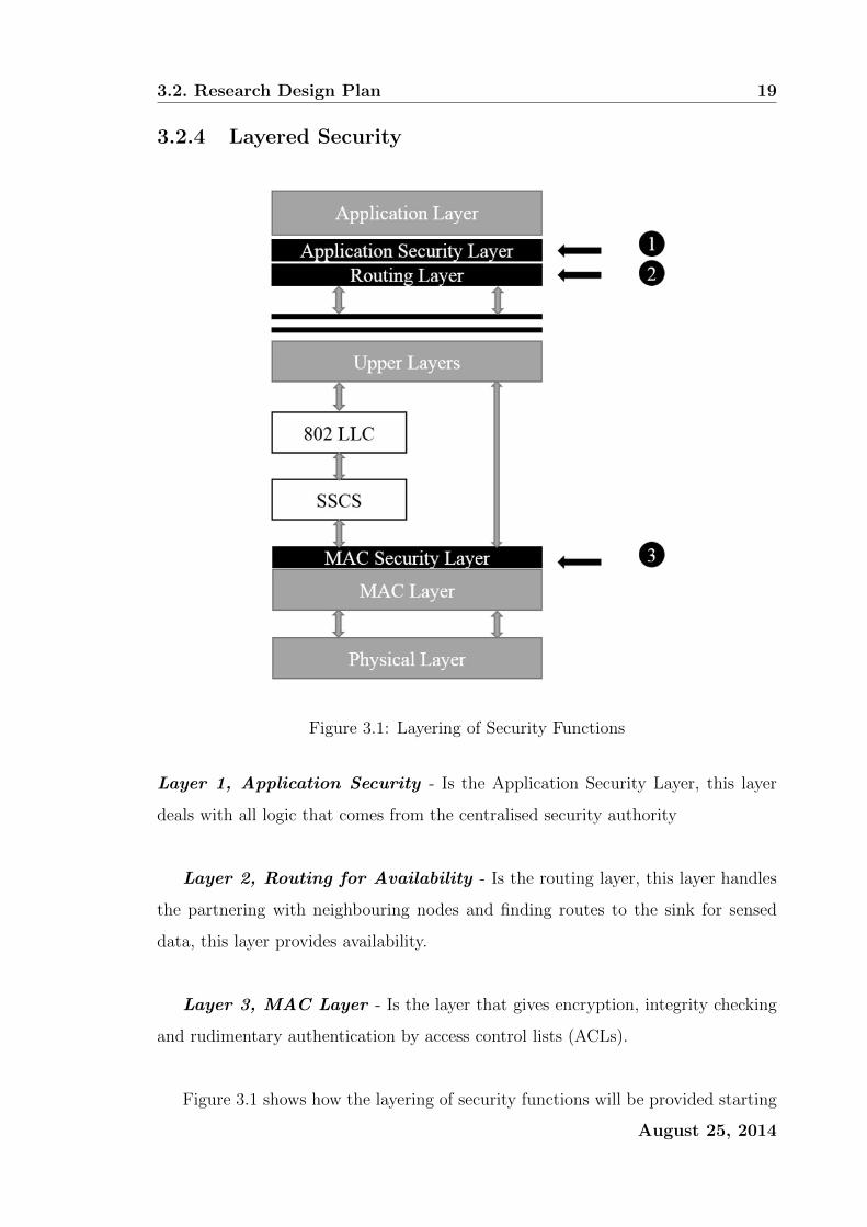
Figure 3.1: Layering of Security Functions
Layer 1, Application Security - Is the Application Security Layer, this layer
deals with all logic that comes from the centralised security authority
Layer 2, Routing for Availability - Is the routing layer, this layer handles
the partnering with neighbouring nodes and finding routes to the sink for sensed
data, this layer provides availability.
Layer 3, MAC Layer - Is the layer that gives encryption, integrity checking
and rudimentary authentication by access control lists (ACLs).
Figure 3.1 shows how the layering of security functions will be provided starting
August 25, 2014

3.2. Research Design Plan 20
from the top. The application security layer (number 1) will be used to translate
commands coming from the gateway into meaningful changes to the nodes’ internal
routing table. If a node has been deemed suspicious by the gateway then the gateway
will broadcast the suspicious node to the network and then that suspicious node will
be penalised. Chapter 6 will go into detail about how this is done and what sort
of actions can be deemed suspicious by the gateway. This layer does not use any
cryptographic methods per say rather it allows for the gateway to issue commands
to the participating nodes in the network.
The routing layer (number 2) as seen in figure 3.1 will be responsible for network
upkeep and network availability. Chapter 4 will go over how this is done. This layer
is responsible for keeping the routing table up to date and also ensuring that nodes
always have a suitable parent to route traffic via to get to the gateway.
The MAC security layer (number 3) as seen in figure 3.1 is the MAC layer as
defined in IEEE 802.15.4 specification. It gives these constrained devices the ability
to perform cryptographic functions. This layer will be responsible for hop-by-hop
encryption, integrity checking and access control. This solution is an extention of
previous work conducted by the author [9]
August 25, 2014

Chapter 4
Least Interference Beaconing
Protocol
This chapter, as similarly previously published by the author [10], presents a frugal
protocol for sensor readings dissemination in the Internet-of-Things (IoT). The pro-
tocol called Least Path Interference Beaconing (LIBP) is based on a lightweight path
selection model that builds a routing spanning tree rooted at the sink node based
on information disseminated through a periodic beaconing process. LIBPs frugality
results from a routing process where the sensor nodes select the least path interfer-
ing parents on the routing spanning tree with the expectation of flow balancing the
traffic routed from nodes to the sink of a sensor network. The simulation results
produced by Cooja under the Contiki operating system are in agreement with pre-
vious results obtained under the TinyOS operating system. They reveal that LIBP
outperforms different versions of the RPL protocol and the CTP protocol in terms
of power consumption, scalability, throughput and recovery from failure as well as
its frugality as a routing protocol.
4.1 Introduction
A new form of modern communication is emerging where sensing, identification and
many other types of processing devices are combined with the objective of interacting
pervasively with the physical world to provide to different users various services. It
21
4.1. Introduction 22
is predicted that these devices will be deployed in our daily living environment
in thousands of heterogeneous computing elements building multi-technology and
multi-protocol platforms that provide access to the information not only ”any time”
and ”anywhere”, but also using ”anything” in a first-mile of the Internet referred to
as the ”Internet-of-the- Things” (IoT) [11]. The next generation IoT infrastructure
is expected to include millions of interconnected islands of sensing/identification
networks spread around the world to provide services that would not be possible to
provide with current generation sensor networks. Such network islands will be using
multi-hop routing to avoid the need for the high communication power that might
be required from the lightweight IoT devices for communication with each other
directly. They will be operating on either an m-to-1 or an m-to-n routing model
where where all the nodes will be collecting from their environments sensor readings
carrying the information to be sent to either a unique sink node (m-to-1 mono-sink
architecture) or multiple sinks (m-to-n multi-sink architecture).
4.1.1 Routing Over Constrained Devices
The routing of sensor readings in IoT settings can be formulated as a problem of
finding a set of paths for routing the traffic flows carrying these readings from their
points of collection to sink nodes which are tasked to deliver these readings to gate-
ways for further processing. When applied to a mono-sink architecture, the traffic
packets carrying the sensor readings are routed from nodes to neighbours along the
path to the unique sink node following a multi-hop process usually aimed at reduc-
ing the energy that each node would spend if it had to send its data traffic directly
to the sink. The process can be constrained by spatio-temporal and different other
constraints depending on the IoT settings and the application. The solutions to the
routing problem above may differ but are usually expected to be self-organized, self-
repairing and frugal routing protocols in terms of storage, processing and communi-
cation requirements on the lightweight devices that are used in IoT deployments. In
a typical mono-sink IoT deployment, the information carried by the sensor readings
would typically be aggregated from the nodes towards a unique sink that forms the
root node of a tree which is connected to the gateway by the sink with most of the
August 25, 2014

4.2. Least Path Interference Beaconing Protocol (LIBP) 23
leaf nodes present in the network sending their sensor readings upwards towards the
root/sink node for storage, analysis or further processing.
4.1.2 Contribution And Outline
The LIBP protocol [12,13] was previously implemented for TinyOS using the Tossim
emulator [14]. This chapter presents a Contiki [15] implementation of LIBP and
evaluates its performance compared to CTP [4] and different versions of the RPL
protocol [5] with the objective of assessing the frugality of LIBP and its efficiency
compared to these two other routing protocols. While the LIBP implementation
presented in this chapter has been implemented from scratch following the model
proposed in [12], the RPL [5] and CTP [4] implementations considered in this chapter
are widely available in open-source format on a wide variety of platforms. They did
not require any new implementation in the platform of choice for this chapter. The
remainder of this chapter is organized as follows: Section 4.2 presents the proposed
LIB protocol while 4.3 describes related routing protocols used in IoT settings. The
results obtained through comparative simulation study are presented in Section 4.4,
and finally Section 4.5 draws the conclusions.
4.2 Least Path Interference Beaconing Protocol
(LIBP)
4.2.1 Protocol description
LIBP [12, 13] is an implementation of the LIBA algorithm. This routing protocol,
like CTP [4], uses a beaconing process initiated by the source (sink) node. When
the process is initiated nodes incident to the sink node will be the first to recognize
that a sink node is within one hop distance. This process is then initiated by these
nodes to their neighbours and this process is repeated thereafter. This results in a
network where each node is aware of its neighbours. The least interference paradigm
is integrated into the process by which nodes select parent nodes which have the
smallest number of (supporting) children, which is the parent of least traffic flow
August 25, 2014
4.2. Least Path Interference Beaconing Protocol (LIBP) 24
interference. This configuration is especially powerful in the situation where sensors
are periodically sensing information (which is a very popular sensor use case). LIBP
basically aims to provide a way to balance traffic flow in such a way that it results in
energy efficiency by having a network where nodes support less traffic. The network
building process is highly detailed in the paper by Bagula et al [12].
4.2.2 LIBP Implementation
RPL and CTP are already implemented in ContikiOS [15], however LIBP is not,
this resulted in having LIBP implemented for Contiki. Following the successful
methodology of adapting CTP to conform to the LIBP model and ideas [12], this
approach was used to preserve the same interfaces that CTP has implemented with
the simulation environment (Cooja). At a very high level the link-estimate module
for CTP found in Contikis network library was modified to conform to LIBP ideas.
This means that the expected transmissions (ETX) link metric was altered to rather
conform to interference represented by the amount of supporting children nodes.
Features not required for LIBP were removed (trickle algorithm code for example).
It should be noted that since LIBP in its Contiki implementation is forked from
CTP’s implementation in Contiki, it inherited the same underlying communications
stack, Rime [16].
4.2.3 LIBP Network Building Process
The LIBP network building owes its power to simplicity that builds upon an ad hoc
routing protocol that is also structurally similar to RPL in structure. LIBP uses
two control plane messages for network configuration, one being the beacon message,
and the other is the acknowledgement (ACK). In the scenario where the network is
initialized, the root node will broadcast a beacon at a given interval where the beacon
includes important routing information regarding the senders identity and weight.
Once the root node advertises the beacon, nodes within the immediate vicinity of
the root would have received the beacon. The root node advertises a weight of 0
which prompts the nodes within its vicinity to use that node as a parent. The parent
August 25, 2014

4.2. Least Path Interference Beaconing Protocol (LIBP) 25
is alerted to the new nodes dependence by the acknowledgement packet. When a
node sends an acknowledgement packet to a parent then that parent must increase
its weight since that parent is supporting an extra node. See Appendix A for an
illustrative protocol description of LIBP.
4.2.4 LIBP Maintenance and Recovery
From the network configuration stage of LIBP (shortly after network epoch) each
node keeps a linked list of neighbouring nodes. This list holds an object which char-
acterizes the neighbouring nodes address and its weight (interference) along with its
route metric.
Maintenance - Since each node accounts for each of its neighbours in a linked
list, it is then possible for nodes to perform rudimentary operations for local network
maintenance, and in the event of parent failure, network repair is achievable. The
age attribute is there to keep track how long that particular LIBPNeighbour has been
in the list, whenever the LIBPNeighbour linked list is updated then the age attribute
is incremented. The route metric attribute describes the precedence in which nodes
are tiered by how far they appear to be from the root node, nodes with a low route
metric are closer to the sink node. RPL uses a similar metric which can be described
as node depth [5].
Recovery - When a node is compromised in such a way that its ability to
communicate is impaired then recovery is required. Such a node would have to be
removed from the network as a whole. This usually happens when a particular node
is unable to acknowledge sent data messages, the main event which alludes to this
conclusion is that a node would have retransmitted the same packet for an amount
that is equal to the programmed maximum retransmits. If this happens then the
compromised node is removed from the sending nodes LIBPNeighbour list. This in
effect removes the parent of the sending node, which requires the sending node to
pick a new parent.
August 25, 2014
4.3. Related Routing Protocols: RPL and CTP. 26
4.3 Related Routing Protocols: RPL and CTP.
4.3.1 Collection Tree Protocol (CTP)
CTP [4] is a routing protocol which extends the Trickle algorithm [17]. It does so
because the assumption can be made that data aggregation is one of the primary
goals of a WSN. CTP promises to be reliable, efficient, robust, and hardware in-
dependent. CTP relies on data packets to validate the routing topology and loop
detection. This routing protocol also utilizes adaptive beaconing (an application of
Trickle) to dynamically setup and adapt to network changes. Every node implement-
ing CTP maintains an estimate of the cost of its route to a collection point (namely,
the sink node). This metric is typically called expected transmissions (ETX).
CTP Network Building Process
CTP (and RPL) employ a similar strategy for network construction. CTP extends
the use of the trickle algorithm [17] by sending out control messages at a rate which
is dependent on how dynamic the network is. In summary when the routing is empty
(the network has just been deployed), A set number of nodes in a network advertise
themselves as network roots. Thereafter, nodes form a set of routing trees to these
roots. In CTP each node selects one parent as a next-hop link and that parent is
closer to the root node than the node is.
CTP Maintenance and Recovery
CTP’s strength lies in the fact that its network maintenance is implied by its adap-
tive control messaging implementation.
Maintenance - The adapted trickle algorithm used in CTP also counts for the
handling of network inconsistencies. These inconsistencies include node addition,
the significant change in link ETX and loop avoidance. The adapted trickle algo-
rithm counts for the ability for CTP to maintain the network. Even if a network is
heavily degraded, due to the adapted trickle algorithm, the network should relax to
a near-optimum state.
August 25, 2014
4.3. Related Routing Protocols: RPL and CTP. 27
Recovery - CTP employs a simple strategy for detecting node failure. In the
case of node failure, all nodes which are dependent on the failed node will find an-
other parent (usually the next best local parent). Node failure is usually recognized
when a node cannot unicast a message to its parent, this is when the node uses up
all its retransmissions for a given packet. Once node failure is established then a
node will do a lookup in its routing table to find the best replacement if possible.
4.3.2 Routing Protocol for LLNs (RPL)
RPL [5] is a direct result of The Internet Engineering Task Force (IETF) which rec-
ognized the need to form a standardized IPv6-based routing solution for LLNs. The
IETF formalized a working group specific for this problem called ROLL (Routing
over Low power and Lossy). The direct outcome of this work group was RPL.
RPL Network Building Process
RPL is a Distance Vector IPv6 routing protocol for LLNs that specifies how to build a
Destination Oriented Directed Acyclic Graph (DODAG) using an objective function
and a set of metrics and constraints. RPL basically builds a logical communications
graph over a physical network that conforms to satisfying a set of objectives and
conforms to a set of constraints which can be set by a network administrator. The
graph building process is initiated at the root (or sink) node, multiple roots can
exist in the same network. The root(s) start advertising the information about the
graph using messages outlined in its RFC and other literature [5].
RPL Objective Functions
An objective function (OF) allows for RPL to optimize, constrain, or scale the rout-
ing metric or link metric of a path. It is entirely possible to have multiple objective
functions operating on the same node or same network. Objective functions allow
network administrators to impose a set of rules which affect the traffic flow of the
network. For example, on one subsection of a network one could implement a rule
that specifies that paths with the best Expected Transmissions (ETX) must be used
August 25, 2014

4.3. Related Routing Protocols: RPL and CTP. 28
and that the paths must be non-encrypted, or that paths with lowest latencies must
be used while avoiding battery operated nodes.
Objective Function ETX - The ETX Objective function (OF-ETX) [4] is a
widely popular link metric in the field of WSN. It is a link metric that in some way
encompasses link congestion and link latency. ETX is simply defined as the expected
number of transmissions required to successfully transmit and acknowledge a packet
on a wireless link. In practical terms the ETXroot = 0 (the root node is not expected
to send data packets) and the ETXnode = ETXparent + ETXlinktoparent. The objec-
tive for OF-ETX is to (greedily) choose the route with the lowest ETX. It should
be noted that OF-ETX is standardized and thus can be considered as a modular
addition to RPL.
Objective Function Zero - The Objective function Zero (OF-0) is a relatively
new objective function proposed by the IETF. In comparison to ETX, OF-0 is not
highly established since ETX is considered a mature link metric in the field of WSNs.
The goal of OF-0 is for a node to select a parent in such a way that it provides or
contributes good enough connectivity to a specific set of nodes or to a larger routing
infrastructure. OF-0 is described as being an OF which guides nodes in their parent
selection using a metric called node rank. The rank computation of OF-0 has a set
of constraints and norms which can be seen in its RFC [18].
RPL Maintenance and Recovery
RPL tries to limit the control plane traffic in the network to minimize the impact
that control plane traffic has on the network. Some protocols use periodic keep
alives (often called beacons) [12]. RPL uses a different paradigm when attempting
to maintain and recover the network.
Maintenance - Instead of using a periodic keep alive for network node main-
tenance, RPL uses an adaptive timer mechanism called the trickle timer. This
algorithm dictates the sending rate of control messages. In essence the trickle timer
August 25, 2014
4.4. Performance Evaluation 29
treats the network as a distributed system that suffers from a consistency problem.
A set of events confirms graph inconsistency, for example if a node detects a loop
then the network is considered inconsistent, or when a node joins a network, or
when a node leaves a network. The more inconsistencies that are detected the more
control messages that are sent in the network. The more consistent the network is
then the less control messages that are sent.
Recovery - RPL employs two techniques in order to recover the network from
node and link failure. In essence RPL uses both local and global repair to initiate
graph recovery. When a link or parent node failure is detected, the child node will
quickly find an alternative route that conforms to the rules of the OF upon it. This is
local repair, given enough local repairs, the graph may diverge from optimum setup.
At this point it may be necessary for the graph to be rebuilt using global repair.
Global repair is the rebuilding of the graph as if the network was newly deployed as
outlined in the RPL Network Building Process section of this chapter. Thus global
repair is costly as that imposes a high flow of control traffic in the network.
4.4 Performance Evaluation
In this section we will be testing the performance of the routing protocols, LIBP,
RPL, and CTP respectively.
Testing Environment - These experiments will be conducted on the Contiki [15]
platform. The mote that will be emulated in Cooja for this experiment will be the
Tmote sky mote. In the case that emulation is not required; Cooja motes will be
used for simulation. The experiment will be conducted in a simulation environment
in which UDGM (Distance Loss) will be the radio medium of choice. RPL and
CTP are already implemented in Contiki. LIBP was implemented by forking the
CTP code found in Contiki and modifying it in order to meet the LIBP requirements.
Data Collection - Metrics in the experiment were collected by implementing
the energest [19](Energy Estimation) module in Contiki, energest is used for ob-
August 25, 2014

4.4. Performance Evaluation 30
taining per-component power consumption. This module gives metrics which are
related to the amount of power required by certain modes of operation. The metrics
that can be obtained from energest is the count of power utilized for radio RX and
TX, Low Powered Mode(LPM), and Normal Powered Mode (NPM) also known as
awake mode. By using the Tmote sky data sheet. The power utilized is described
below.
To calculate the power we need an intermediary function which helps us calculate
the power utilized.
f(x, y) = ((x× 64) + (y × 64)/1000) (4.4.1)
And to calculate the power utilized given the energest RX TX LPM and NPM
values we calculate the power.
P = 3×NPM × f(1, 800) + LPM × f(0, 545) + TX × f(17, 700) +RX × f(20, 0)
64 × (NPM + LPM) ÷ 1000(4.4.2)
Cooja also has an online data collection application called the shell collect view.
The shell collect view gives a comprehensive breakdown of node specific status vari-
ables and meta-data. Cooja has another nice feature which comes in a Cooja appli-
cation called Power Tracker. Power Tracker is an online real-time radio duty cycle
monitoring tool. PowerTracker can be used to deduce the amount of time that a
node spends in a particular state with regards to its radio.
Testing Variables - RPL will be run as two experiment instances since RPL
can be run with various objective functions (OF). As a result RPL will be run with
OF-0 and OF-ETX and thus for the rest of the chapter RPL will be referred to
either RPL-0 or RPL-ETX to refer to RPL coupled with their objective functions
respectively. RPL itself cannot be tested as a routing protocol rather RPL and
an objective function needs to be tested against CTP and LIBP respectively. Since
there are implementations for OF-0 and OF-ETX on Contiki already, the experiment
variables will be the routing protocols, CTP, LIBP, RPL-0, and RPL-ETX.
August 25, 2014

4.4. Performance Evaluation 31
Test Attributes Test Value
Topology 175mx175m grid of 30 randomly placed nodes (density
30m2/node)*
Beacon Interval 30 seconds (LIBP), Adaptive (CTP, RPL)
Messaging Interval 30 seconds
Message Contents Hello from node
Simulation Runtime 10 minutes (2 minutes for network self organization)*
(LIBP) 1
TX/INT Range 50m/100m
Table 4.1: Simulation Setup
4.4.1 Methodology
Table 4.1 above outlines the experiment runtime. In short, unless otherwise speci-
fied, the networks are each given a 2 minute period to allow for the network to settle;
thereafter the network is run for 8 minutes to give a total simulation runtime of 10
minutes. Each node will periodically send a packet containing the string ”Hello from
node” as its packet data. Since each node is given 8 minutes to send the data at a
period of 30 seconds, the nodes will each send 16 packets data to be collected by the
sink. For the various experiments, all of Coojas existing profiling tools were used
as experimentation tools. Simulation timers and node real-time timers were used as
experimentation tools for time sensitive experiments. For discerning between control
plane traffic and data plane traffic the packets were flagged accordingly, the packets
would then trigger a counter which would hold a value that shows how many times a
packet of that particular classification occurred as traffic during simulation runtime.
Routing protocols have to be tested in terms of scalability. 10 random topologies
were generated ranging from a topology sizes of 10 to 100 (in increments of 10).
Each topology had the same node density. The benefit of having all these network
topologies is so that metrics related to the routing protocols can be observed while
the topology size increases.
August 25, 2014
4.4. Performance Evaluation 32
4.4.2 Results and Evaluation
In this section, CTP, and RPL (alongside its OFs) is evaluated against the new
implementation of LIBP on Contiki.
Energy Profile
CTP LIBP RPL-0 RPL-ETX
3.5
4
4.5
5
5.5
Ave
rage
Pow
erC
onsu
mpti
on(m
W)
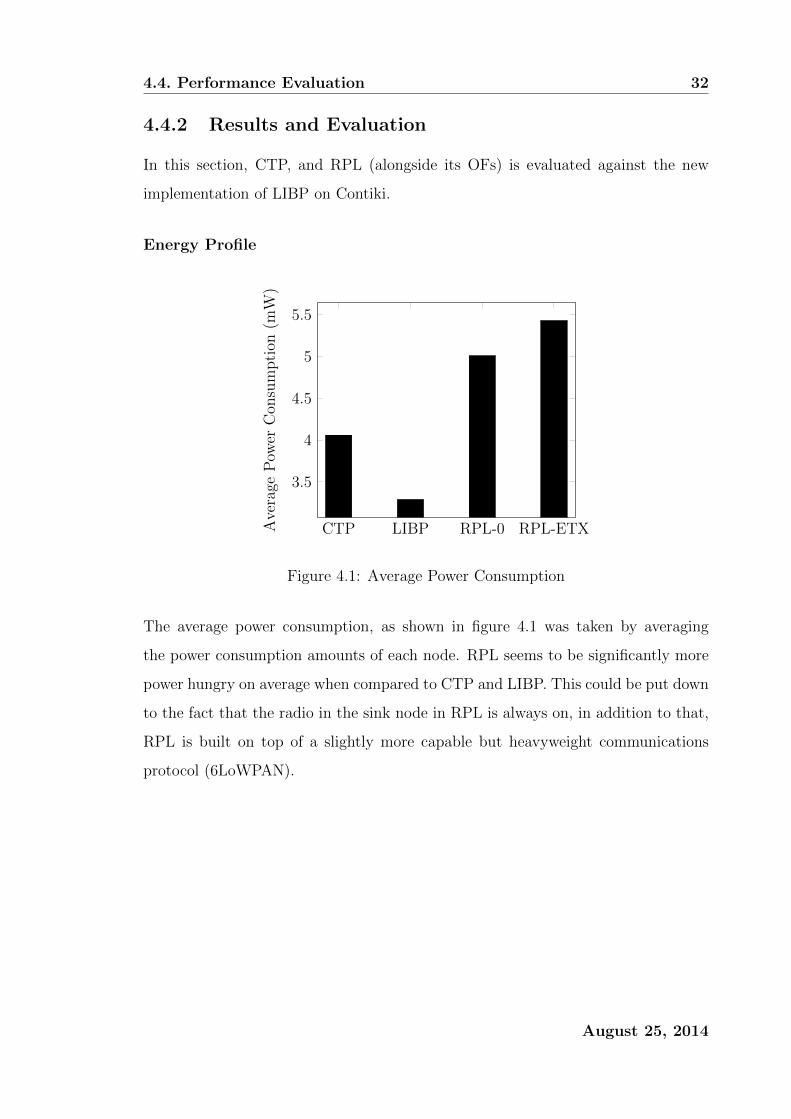
Figure 4.1: Average Power Consumption
The average power consumption, as shown in figure 4.1 was taken by averaging
the power consumption amounts of each node. RPL seems to be significantly more
power hungry on average when compared to CTP and LIBP. This could be put down
to the fact that the radio in the sink node in RPL is always on, in addition to that,
RPL is built on top of a slightly more capable but heavyweight communications
protocol (6LoWPAN).
August 25, 2014
4.4. Performance Evaluation 33
CTP LIBP RPL-0 RPL-ETX
0.2
0.4
0.6
0.8
Tim
e(%
)
RXTXINT
Figure 4.2: Radio Duty
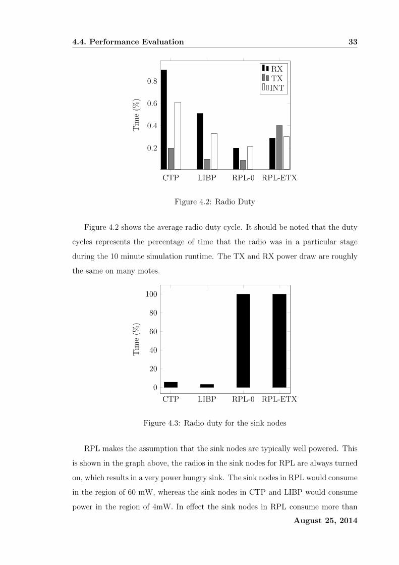
Figure 4.2 shows the average radio duty cycle. It should be noted that the duty
cycles represents the percentage of time that the radio was in a particular stage
during the 10 minute simulation runtime. The TX and RX power draw are roughly
the same on many motes.
CTP LIBP RPL-0 RPL-ETX
0
20
40
60
80
100
Tim
e(%
)
Figure 4.3: Radio duty for the sink nodes
RPL makes the assumption that the sink nodes are typically well powered. This
is shown in the graph above, the radios in the sink nodes for RPL are always turned
on, which results in a very power hungry sink. The sink nodes in RPL would consume
in the region of 60 mW, whereas the sink nodes in CTP and LIBP would consume
power in the region of 4mW. In effect the sink nodes in RPL consume more than
August 25, 2014
4.4. Performance Evaluation 34
1 order of magnitude more energy than the CTP and LIBP sink nodes. This can
mostly be put down to the always on radio.
10 20 30 40 50 60 70 80 90 100
3
4
5
6
7
8
9A
vera
geP
ower
Con
sum
pti
on(m
W)
CTPLIBPRPL-0
RPL-ETX
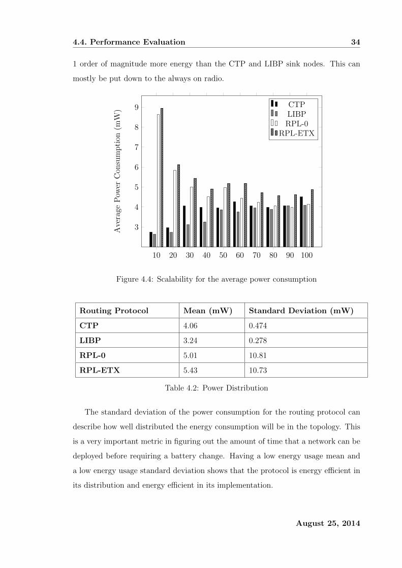
Figure 4.4: Scalability for the average power consumption
Routing Protocol Mean (mW) Standard Deviation (mW)
CTP 4.06 0.474
LIBP 3.24 0.278
RPL-0 5.01 10.81
RPL-ETX 5.43 10.73
Table 4.2: Power Distribution
The standard deviation of the power consumption for the routing protocol can
describe how well distributed the energy consumption will be in the topology. This
is a very important metric in figuring out the amount of time that a network can be
deployed before requiring a battery change. Having a low energy usage mean and
a low energy usage standard deviation shows that the protocol is energy efficient in
its distribution and energy efficient in its implementation.
August 25, 2014

4.4. Performance Evaluation 35
4.4.3 Routing Profile
The routing metrics of each routing protocol include the amount of supporting
children per node, the average path length and the agility of the protocol.
CTP LIBP RPL-0 RPL-ETX
4
4.5
5
5.5
6A
vera
geSupp
orti
ng
Childre
nP
erN
ode
Figure 4.5: Contention
Figure 4.5 above shows the average amount of children that a node would sup-
port. This value was obtained by counting the amount of times each node referenced
a parent and then averaging those values. Having a smaller number of average chil-
dren is a desirable metric because it can help with energy distribution in the network
which helps with leaving all the nodes at more or less the same battery life. Having a
high contention un-desirable since it may also introduce a higher rate of packet loss
or interference into the network. LIBP being the protocol which tries to minimize
the average amount of children in the pursuit for better energy distribution does
better in this experiment.
August 25, 2014

4.4. Performance Evaluation 36
CTP LIBP RPL-0 RPL-ETX
3.5
4
4.5
5
Ave
rage
Pat
hL
engt
h(H
ops)
Figure 4.6: Average Path Length
The average path length was obtained by obtaining the TTL like attributes in
the protocol control plane packets. LIBP and RPL use TTL (time to live) however
CTP uses time has lived (which is TTLMAX − TTL). Once the number of hops was
obtained they were averaged to give an average path length metric for each protocol
respectively. Depending on the application, A high average path length is desirable
for better for energy distribution but a lower average path length can result in a
lower latency between the leaf nodes and sink nodes.
CTP LIBP RPL-0 RPL-ETX
40
50
60
70
Rec
over
yT
ime
(s)
Figure 4.7: Time taken for node to recover from network failure
Figure 4.7 above shows how quickly the protocols can come up with contingency
routes if a node with high contention fails. To simulate this event, a node with a
August 25, 2014

4.4. Performance Evaluation 37
high degree of children (4 children) was chosen and deleted at the 10 minute mark.
The times represented in the graph above shows the amount of time required for all
4 of the children to find alternate parents/routes. The data above shows how agile
the routing protocols are in terms of how they deal with catastrophic failure.
CTP LIBP RPL-0 RPL-ETX
20
30
40
50Joi
nT
ime
(s)
Figure 4.8: Time taken for a new node to join the network
Figure 4.8 demonstrates how agile the protocols are in the ad hoc sense. The
experiment was set up by running a normal collect experiment of 30 nodes, except
1 node would be out of reach from the network (thus not part of the network). At
the 10 minute mark from the start of the simulation the secluded node would be
introduced to the network. The times in the above graph represent the time it took
for that node to have acknowledged a parent (to become part of the network).
August 25, 2014

4.4. Performance Evaluation 38
4.4.4 Traffic Profile
Messages Sent Beacons Sent Acks Sent
500
1,000
1,500
2,000
2,500
Num
ber
ofP
acke
ts
LIBPCTP
Figure 4.9: Control Packets Sent
It is a worthwhile effort to see how much energy is spent on the control plane as
opposed to the data plane. It should be noted that in the case of CTP, since beacon
information piggybacks on data transmission, it counts as a beacon sent.
Protocol Success Rate
CTP 99.7%
LIBP 99.7%
RPL-0 100%
RPL-ETX 100%
Table 4.3: Successful Transmission Rate
Table 4.3 describes the percentage of data packets that were collected by the sink
node. Most packets were successfully collected by CTP and LIBP by achieving a
higher than 99% transmission to the sink node. RPL achieved a 100% transmission
rate. This astounding transmission rate could be attributed to how complete the
communications protocol that RPL is built on top of is. Whereas CTP and LIBP
are built on top of Rime [16].
August 25, 2014
4.5. Analysis, and Conclusion 39
4.5 Analysis, and Conclusion
This chapter presents a comparison between routing protocols. Experiments were
conducted between CTP, LIBP and RPL. The simulations revealed that CTP and
LIBP are relatively light in their implementation and goals but lack a few features
that RPL has like mote to mote communication. RPL also can utilize the full stack
of security mechanisms present in IPv6. The inherent heaviness of RPL can be
attributed to its underlying protocol and how the underlying protocol uses larger
more feature rich packets. CTP and LIBP are very similar in their performance
metrics, this could be attributed to the fact that they both use the same underlying
communications stack. CTPs strength lies in its very agile nature. CTP’s trickle
timer allows it to react to adverse changes in the network very quickly. One of
LIBP’s main goals was to have a routing protocol that was more efficient in its
global energy consumption. This resulted in a protocol that is very efficient in how
each node in the network consumes a similar amount of energy, and when compared
to CTP and RPL, LIBP does a better job in this area.
August 25, 2014

Chapter 5
Communications Cryptography
As mentioned in the previous chapters, especially Chapter 2, having the option
for confidentiality in communications is a well wanted function for a constrained
network. In this chapter we evaluate and compare various methods of encryption
and their mechanisms.
5.1 Introduction
The major challenge in these types of networks is that usually the nodes are short
in computational power and storage capacity because they are simple devices with
much less power requirements than most computational devices. Therefore doing
complex encryption methods like frequency hopping and public key encryption is
very difficult to set up, especially in a Low-powered and Lossy Network. However
attacks on the network against confidentiality are still a great concern.
In this Chapter we discuss the various encryption mechanism available as speci-
fied in the IEEE 802.15.4 specification.
5.1.1 IEEE 802.15.4 Overview and Security
The IEEE 802.15.4 describes a wireless media access protocol for personal area net-
working devices. This protocol is widely used in the constrained network community
as well. The 802.15.4 specification is designed to be implemented in hardware on
40

5.1. Introduction 41
a radio controller [20]. The feature set of the 802.15.4 specification contains some
security focused aspects, that can cater to a wealth of use cases.
The way that nodes are addressed in 802.15.4 is done by a 64-bit node identifier
and a 16-bit network identifier. However the addressing mode is customizable to
suit the needs of the deployment. The packet types which are relatively important
especially in terms of security are the data packets and the acknowledgement packets.
A data packets’ length can vary in length and can be used for both unicast and
broadcast messages. Each packet has a collection of flag fields that denote the
packet type, mode of operation, security used, and whether the sending node is
expecting an acknowledgement. A sequence number also exists in the packet and
this is used to identify the packet and the sequence number is also used to guard
against replay attacks. Most of the security in IEEE 802.15.4 is handled in the
media access control layer (MAC). A constrained network can define its own type
of security protection, There are 8 types of security settings that guarantee different
security options as seen in table 5.1.
Figure 5.1: IEEE 802.15.4 Packet Description
August 25, 2014
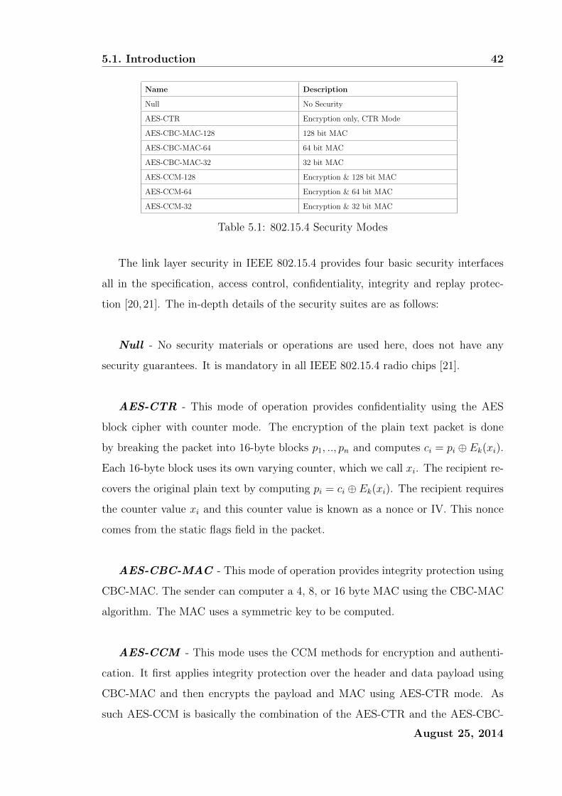
5.1. Introduction 42
Name Description
Null No Security
AES-CTR Encryption only, CTR Mode
AES-CBC-MAC-128 128 bit MAC
AES-CBC-MAC-64 64 bit MAC
AES-CBC-MAC-32 32 bit MAC
AES-CCM-128 Encryption & 128 bit MAC
AES-CCM-64 Encryption & 64 bit MAC
AES-CCM-32 Encryption & 32 bit MAC
Table 5.1: 802.15.4 Security Modes
The link layer security in IEEE 802.15.4 provides four basic security interfaces
all in the specification, access control, confidentiality, integrity and replay protec-
tion [20,21]. The in-depth details of the security suites are as follows:
Null - No security materials or operations are used here, does not have any
security guarantees. It is mandatory in all IEEE 802.15.4 radio chips [21].
AES-CTR - This mode of operation provides confidentiality using the AES
block cipher with counter mode. The encryption of the plain text packet is done
by breaking the packet into 16-byte blocks p1, .., pn and computes ci = pi ⊕ Ek(xi).
Each 16-byte block uses its own varying counter, which we call xi. The recipient re-
covers the original plain text by computing pi = ci ⊕ Ek(xi). The recipient requires
the counter value xi and this counter value is known as a nonce or IV. This nonce
comes from the static flags field in the packet.
AES-CBC-MAC - This mode of operation provides integrity protection using
CBC-MAC. The sender can computer a 4, 8, or 16 byte MAC using the CBC-MAC
algorithm. The MAC uses a symmetric key to be computed.
AES-CCM - This mode uses the CCM methods for encryption and authenti-
cation. It first applies integrity protection over the header and data payload using
CBC-MAC and then encrypts the payload and MAC using AES-CTR mode. As
such AES-CCM is basically the combination of the AES-CTR and the AES-CBC-
August 25, 2014
5.1. Introduction 43
MAC modes of operations.
5.1.2 Keying Modes
In symmetric cryptography, there are various modes of keying that nodes of the net-
work must adhere to. The keying model used must be appropriate to a particular
use case and must also be chosen based on what sort of resources an application
developer is willing to pay for in terms of energy.
Network Shared Keying - Each node in the network possess the same key,
and the same key is used throughout the network for each node to communicate with
each other. Key management in this case is trivial since all communications use the
same key. Also the memory footprint of this keying mode is most minimal [21].
The only problem with this keying mode is that this mode is vulnerable to in-
sider attacks. also since a single key is used, it means that all nodes in the network
could be compromised should the network key be discovered. Even though Network
Shared Keying may seem quite vulnerable, it should only be used in non-critical use
cases.
Pairwise Keying - Pairwise keying is when each node pair of nodes share
a set of keys. Thus for every node, a particular node will have a key for all its
neighbouring nodes at least. This has a lower risk of a network compromise if a
node is hijacked since only one node will affected, only past and future messages to
and from that node will be compromised. This provides better security than the
Network Shared Mode since it does not compromise the network in its entirety [21].
Group Keying - Group Keying Mode is a mix between pairwise and network
shared keying. A single key is shared among a set of nodes and is used to set up
network groups between a set of nodes. The partition of nodes may be based on
locale or network topology. The trade-off here is that if a key is compromised or
August 25, 2014
5.1. Introduction 44
a node is hijacked that particular group is also compromised by an attacker node.
However it still does not compromise the network in its entirety especially if the
grouping was done correctly.
Hybrid Approaches - Some use cases may dictate a combination of the above
3 Keying Modes simultaneously. For example, we may have a sensor farm (or sensor
island) which connects to a gateway via a hop-by-hop backbone network, one could
argue that a group key for the sensor farm is a good option and that the backbone
network should use pairwise keying.
5.1.3 CIA in IEEE 802.15.4
Confidentiality - Confidentiality sometimes implies the use of encryption to keep
messages a secret from unauthorized third parties. When it comes to semantic se-
curity, which is preventing partial information from being observed. One example
of a semantic security failure is if the same message encrypted twice yielded two of
the same cipher texts. A technique for achieving semantic security is to use a nonce,
a nonce is basically a uniquely generated identifier that can be piped into the plain
text to produce a different cipher text each time. The main purpose of a nonce is
to make sure that each invocation of encryption would yield a sufficiently different
nonce. Typically nonces are sent in clear text and are included in the same packet
with the encrypted data.
Authentication and Integrity - IEEE 802.15.4 allows for the use of Access
Control via means of Access Control Lists (ACL). This all happens at the link layer
which in turn safeguards the network against any parties who are not authorized
to participate in the network. Trusted nodes have the ability to detect untrusted
nodes by rejecting messages that come from entities that are not present in the
ACL. If an adversary modifies a message from an authorized sender, it should also
be detectable since the messages integrity is being attacked. The IEEE 802.15.4 al-
lows for integrity checking or tampering checking by using Message Authentication
August 25, 2014
5.1. Introduction 45
Codes (MAC) [21]. Each packet has with it a message authentication code attached
to it and subsequently can be used to check the integrity of a message. A MAC is a
cryptographic checksum for a string. Computing it requires parties to share a secret
cryptographic key and this key is used in the MAC computation process. MACs
have the property that they must be hard to forge without the key.
Replay Protection - IEEE 802.15.4 employs the same sort of replay attack
protection that other similar networking standards use [20, 21]. An attacker who
eavesdrops on a communications exchange between two authorized parties can then
replay the messages again at a later time, this is known as a replay attack. Since
the original message sent had a valid MAC the attacker can just re-send the same
packet so that it looks like it came from the authorized originator, and the receiver
will accept the message again. To get past replay attacks all packets are assigned
a monotonically increasing sequence, and if a packet received has a sequence num-
ber that is less than one that has been already accepted then that packet is dropped.
5.1.4 IEEE 802.15.4 Drawbacks
Sastry and Wagner have identified several vulnerabilities in the IEEE 802.15.4 spec-
ification and they fall into the categories: Key Management, Integrity Protection,
and Initialisation Vector (IV) Issues. According to the literature, IEEE 802.15.4,
if used incorrectly by developers, can provide less security than what one might
expect [21].
Key Management
Group Keying Not Supported - Attempting to implement group keying in IEEE
802.15.4 is really cumbersome. As Sastry and Wagner pointed out, If nodes n1, ..., n5
wished to communicated amongst each other using key k1, while nodes n6, ..., n9 use
k2. Because each ACL entry can only be associated to a single destination address,
there is no good way to support this use case. One way around this is to create 5
ACL entries, one for each node, all mentioning the same key k1. This requires that
August 25, 2014
5.1. Introduction 46
the radio be large enough to all these ACL entries [21]. However as will be discussed,
is that the ACL Table could contain the same keys in multiple ACL entries which
can lead to more security risks. It is a very bad idea to consider this use case in
conjunction with IEEE 802.15.4. Another proposed workaround would be to create
a single ACL entry for key k1. Before sending to node n1, the destination address
associated with that ACL entry could be changed to mention n1. If the application
wants to communicate with n2 with the same key, it must then switch the destina-
tion address. In essence the destination address of that particular ACL entry must
be modified every time the sender wants to send to a new destination within the
group. This makes packet transmission cumbersome. The only problem with this
is that the receiver also needs to do the same thing prior to receiving the packets.
This is usually not possible unless the network has predictable networking patterns.
Network Shared Keying Incompatible with Replay Protection - When
using a single wide network shared key, there is no way to protect against replay
attacks. To use a network shared key model an application must use the default
ACL entry, recall that when there is no matching ACL entry for a sender, then the
default ACL entry will be used.
Now in the case that the network shared key is loaded into the default ACL
and node s1 sends 100 messages using replay counters 0..99. The recipient would
like to perform replay protection however it must keep a high mark of what the
largest replay counter it has seen. According the the IEEE 802.15.4 specification,
the receiver updates the replay counter associated with the default ACL as each
packet arrives. Now if a sender s2, sends a message with its replay counter starting
at 0, the recipient will reject that packet, in essence the recipient will only be able
to accept high sequence valued packets from its neighbouring nodes.
Pairwise Keying Inadequately Supported - The specification as it stands
does not have strong support for pairwise keying. The specification allows for a
802.15.4 radio to have up to 255 ACL entries, however it does not specify a minimum
amount. In essence OEMs could manufacture radios with support for only two
August 25, 2014
5.1. Introduction 47
ACL entries, in a ubiquitous network of constrained devices this could result to the
networks’ ACL entry will be limited by the device with the smallest amount of ACL
entries.
Integrity Protection
Unauthenticated Encryption Modes - As per Table 5.1, the AES-CTR mode
uses counter mode without a MAC. The standard itself does not require that radio
designers support the CTR mode. Only is it mandatory in AES-CCM-64. Sastry
and Wagner stated that AES-CCM-64 is a mode that should never be used since
unauthenticated encryption allows for a significant amount of security risk to creep
into the protocol. In 802.11, IPSec, and SSH , Researchers [20, 21] have discov-
ered that there are unauthenticated encryption vulnerabilities that are applicable
to IEEE 802.15.4 as they are in IEEE 802.11.
What should also be noted is that application developers who are not well versed
in cryptography may not realise that failure to do integrity checks can affect confi-
dentiality as well. This can be done by an attacker can forge an unauthentic message
often tricking another network entity into disclosing secret material. The severity
of a problem like this depends on the use case however researchers [20,21] stress the
use of of encryption with a MAC, otherwise you impose a higher security risk of
breaches. Thus AES-CTR should never be used in isolation.
DoS Attacks on AES-CTR - In an IEEE 802.15.4 network, consider the
following situation. When an IEEE 802.15.4 network uses the AES-CTR mode of
operation with replay protection enabled. A sender s and recipient r communicate
with the AES-CTR mode with a key k. It should be noted that the recipient does
keep a counter composed of the key and frame counter, which drops packets whose
counter is smaller than the highest current counter value. Suppose an attacker
sends a forged packet with the source address s, key k and counter 0xFF and frame
counter 0xFFFFFFFF . When the actual legitimate sender s tries to send any
information to r then r will automatically drop the packet and all packets then on
from s. Since the packet with the highest counter has been sent, all packets from s
August 25, 2014

5.1. Introduction 48
will be detected as being replayed. The attack is trivial to set up which makes it a
high risk attack.
Lack of Acknowledgement Packet Integrity Checking - As far as the
specification goes, 802.15.4 specification does not mandate any confidentiality pro-
tection or integrity protection for acknowledgement packets. The request for an
acknowledgement from a recipient is an optional action by setting a bit in the flags
field. If the bit is set then by the standard the recipient has to return an acknowl-
edgement packet that contains the received packets’ sequence value.
This security flaw can be further exploited by adding targeted jamming to pre-
vent the delivery of packets. The attacker can transmit a short burst of interference
while the packet is being sent, causing the CRC of that particular packet to be in-
valid to the recipient. Then the attacker can forge a valid-looking acknowledgement
packet, causing the sender to think that the packet has been sent and received well.
This particular attack causes concern for the security of these packets. If acknowl-
edgement packets form a critical part of your network for reliable transmissions then
this attack carried out on the network could cause harm. Researchers [20,21] claim
at this point in time, acknowledgements should be used loosely and not relied upon
in a critical fashion.
Acknowledgement packets should be developed on the application level, since
802.15.4 provides MAC and encryption for application level packets. This solution
is certainly quite complex however it is the only safe option.
IV Issues
Same Key in Multiple ACL Entries - The IEEE 802.15.4 specification allows
for up to 255 ACL entries which are used to store node keys and nonces. The
ACL entry is chosen by checking which entry is associated with which address. The
sender chooses an ACL entry based on what destination address is being used. A
vulnerability within the specification exists where the sender will unwittingly use
August 25, 2014

5.2. Performance Evaluation 49
reuse the nonce. In the case that AES-CCM-64 is used and the same key k is used
for recipient r1 and recipient r2 and initialises the frame and key counters to both
0x0. If the sender transmits message m1 with data 0xAA00 to r1 and then a message
m2 with the data 0x00BB to r2, the sender will use the same nonce for both the
frame counter and key counter 0x0. This is due to the fact that each ACL entry
in its own right has it’s own independent nonce state. Since AES-CCM uses CTR
mode, an adversary can recover the XOR of the plain texts by computing the XOR
of the two cipher texts, completely breaking the confidentiality property.
Loss of ACL State Due to Power Interruptions - IEEE 802.15.4 devices
are normally going to be of the constrained type which rely on stored energy or so-
lar power. When power failure occurs, if no context saving is done, then the device
will recover from power failure with a clear ACL table. In some cases the nodes
software could repopulate the ACL table with the desired keys, however the nonce
state restoration is not all that clear. Researchers [20,21] suggest to store the nonce
states into flash memory, however storing into flash memory is slow and expensive
in terms of energy usage.
Low Powered Operation - Similarly to the previous problem surrounding
power interruptions, is how to preserve the nonce state when the devices are duty
cycling for power conservation reasons. The IEEE 802.15.4 specification does not
specify what sort of practices should be taken when a device comes out of a low
powered state (that resets the ACL table). Using the same solution as the one sug-
gested in the power interruption scenario is expensive and costly in terms of energy
usage.
5.2 Performance Evaluation
Testing Environment - The experiments conducted were done so on the Contiki
platform. The mote emulated in this experiment will be the Tmote sky mote. The
August 25, 2014

5.2. Performance Evaluation 50
simulation will be conducted in a simulation environment in which UDGM (Distance
Loss) will be the radio medium of choice. IEEE 802.15.4 can be used in the three
unlicensed frequency bands 868/902/2400 MHz, since this research was conducted in
South Africa, the only viable option to run an evaluation on was the 2400MHz band.
Data Collection - Various methods were used to collect data in this evaluation.
The energy related experiments used the energest module in Contiki, this module
gives a per-module energy usage report for a particular node if set up correctly. The
simulation environment for Contiki, called Cooja, will also be used to collect node
and network-wide statistics. Unless otherwise specified, these tests were conducted
in a span of 10 minutes and each data packet was 512 bytes in length.
5.2.1 Methodology
For the performance evaluation of IEEE 802.15.4 and it’s security modes. We need
only look at the throughput and performance as seen from the MAC-Layer. At the
very least these experiments will give an upper bound to the practical possibilities
of the protocol. The maximum throughput is calculated between only one sender
and one receiver which are located close to one another (10 meters) So in this case,
packet loss is minimised, and the sender always has packets queued in the buffer to
send.
The maximum throughput (TP) is calculated similarly to how Latre do it.
TPmax =8 • x
delay(x)(5.2.1)
In this formula, x is the number of bytes that has been received from the network
layer. Take note that for packets that require ACK packets this time is slightly
increased as the total formula for delay can be expressed as:
delay(x) = TBO + Tframe + TACK + TTA + TCRY (5.2.2)
Where the variables are:
TBO = Back off period in seconds
August 25, 2014
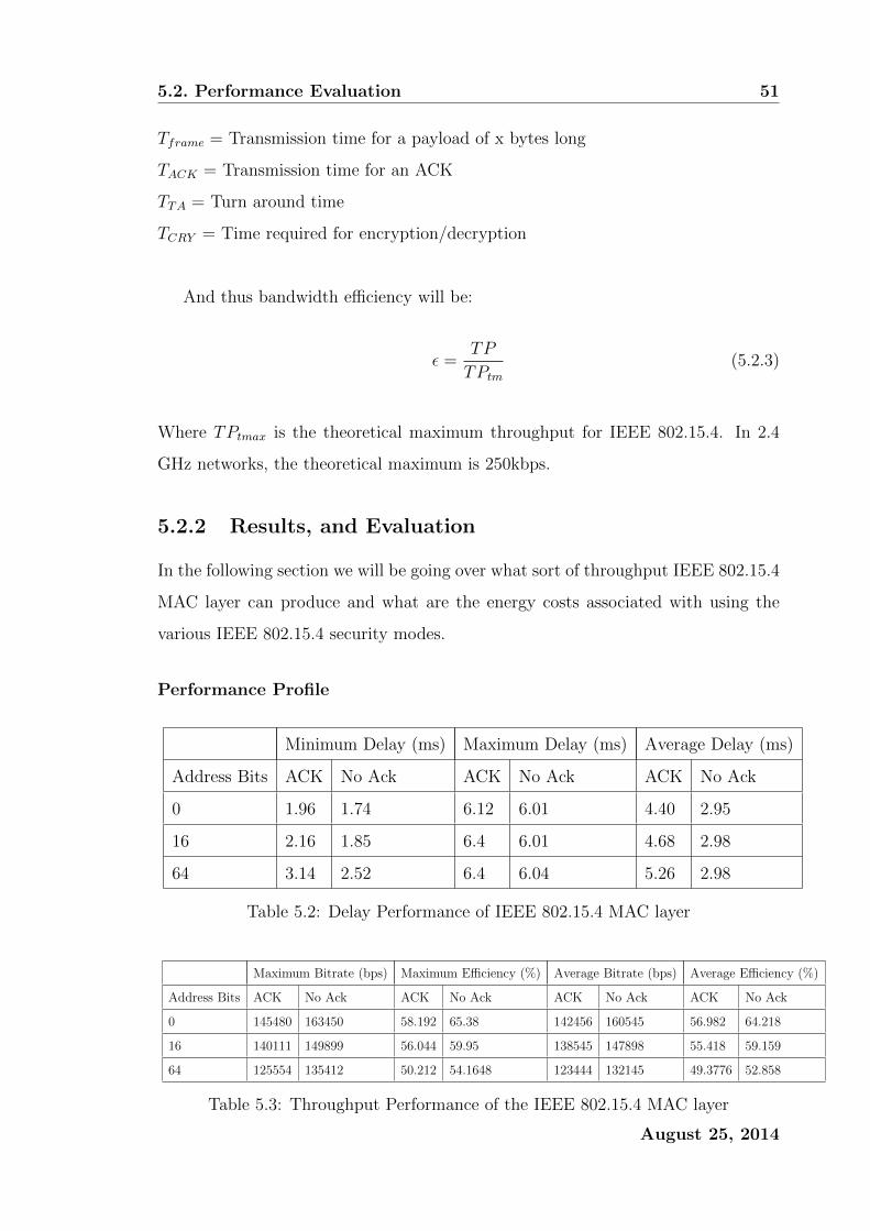
5.2. Performance Evaluation 51
Tframe = Transmission time for a payload of x bytes long
TACK = Transmission time for an ACK
TTA = Turn around time
TCRY = Time required for encryption/decryption
And thus bandwidth efficiency will be:
ε =TP
TPtm
(5.2.3)
Where TPtmax is the theoretical maximum throughput for IEEE 802.15.4. In 2.4
GHz networks, the theoretical maximum is 250kbps.
5.2.2 Results, and Evaluation
In the following section we will be going over what sort of throughput IEEE 802.15.4
MAC layer can produce and what are the energy costs associated with using the
various IEEE 802.15.4 security modes.
Performance Profile
Minimum Delay (ms) Maximum Delay (ms) Average Delay (ms)
Address Bits ACK No Ack ACK No Ack ACK No Ack
0 1.96 1.74 6.12 6.01 4.40 2.95
16 2.16 1.85 6.4 6.01 4.68 2.98
64 3.14 2.52 6.4 6.04 5.26 2.98
Table 5.2: Delay Performance of IEEE 802.15.4 MAC layer
Maximum Bitrate (bps) Maximum Efficiency (%) Average Bitrate (bps) Average Efficiency (%)
Address Bits ACK No Ack ACK No Ack ACK No Ack ACK No Ack
0 145480 163450 58.192 65.38 142456 160545 56.982 64.218
16 140111 149899 56.044 59.95 138545 147898 55.418 59.159
64 125554 135412 50.212 54.1648 123444 132145 49.3776 52.858
Table 5.3: Throughput Performance of the IEEE 802.15.4 MAC layer
August 25, 2014
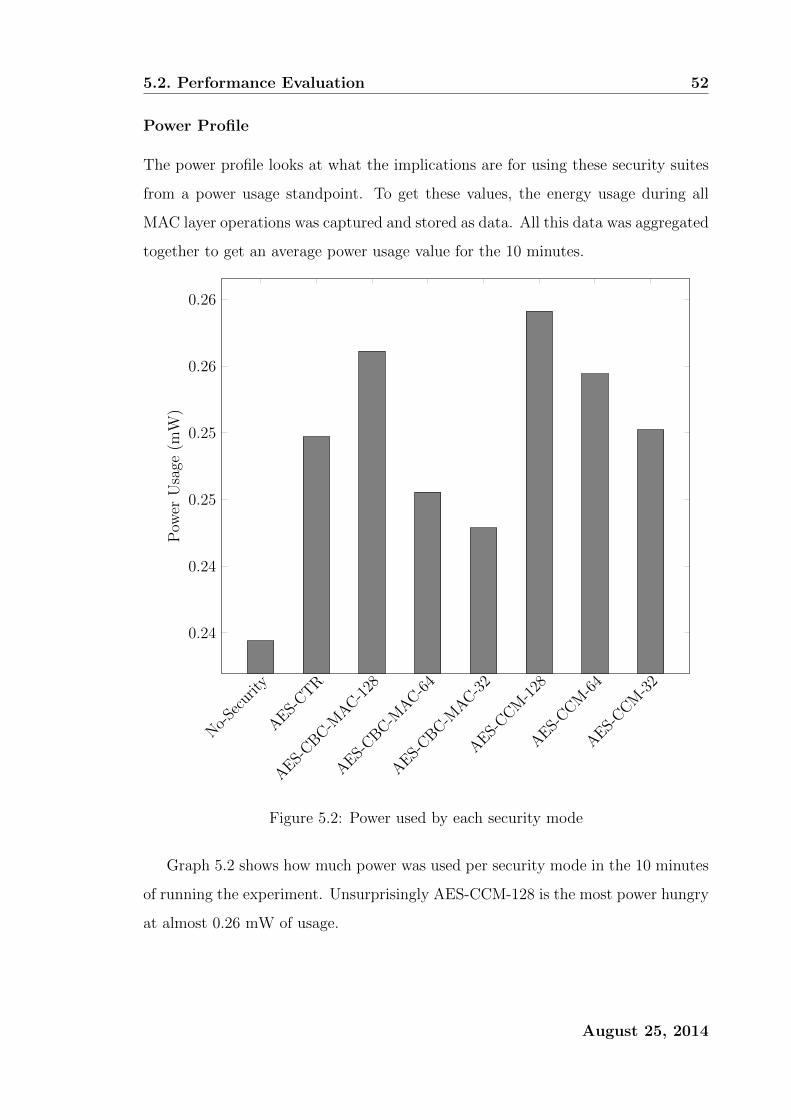
5.2. Performance Evaluation 52
Power Profile
The power profile looks at what the implications are for using these security suites
from a power usage standpoint. To get these values, the energy usage during all
MAC layer operations was captured and stored as data. All this data was aggregated
together to get an average power usage value for the 10 minutes.
No-
Secu
rity
AES-
CTR
AES-
CBC-MAC-1
28
AES-
CBC-MAC-6
4
AES-
CBC-MAC-3
2
AES-
CCM-1
28
AES-
CCM-6
4
AES-
CCM-3
2
0.24
0.24
0.25
0.25
0.26
0.26
Pow
erU
sage
(mW
)
Figure 5.2: Power used by each security mode
Graph 5.2 shows how much power was used per security mode in the 10 minutes
of running the experiment. Unsurprisingly AES-CCM-128 is the most power hungry
at almost 0.26 mW of usage.
August 25, 2014
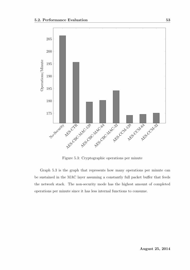
5.2. Performance Evaluation 53
No-
Secu
rity
AES-
CTR
AES-
CBC-MAC-1
28
AES-
CBC-MAC-6
4
AES-
CBC-MAC-3
2
AES-
CCM-1
28
AES-
CCM-6
4
AES-
CCM-3
2
175
180
185
190
195
200
205O
per
atio
ns/
Min
ute
Figure 5.3: Cryptographic operations per minute
Graph 5.3 is the graph that represents how many operations per minute can
be sustained in the MAC layer assuming a constantly full packet buffer that feeds
the network stack. The non-security mode has the highest amount of completed
operations per minute since it has less internal functions to consume.
August 25, 2014

5.3. Analysis, and Conclusion 54
Security Mode Energy Cost (%)
No Security 0
AES-CTR 6.530
AES-CBC-MAC-128 9.261
AES-CBC-MAC-64 4.756
AES-CBC-MAC-32 3.609
AES-CCM-128 10.543
AES-CCM-64 8.535
AES-CCM-32 6.752
Table 5.4: Energy penalty per security mode
Only counting the operations that happen that support the MAC layer, table 5.4
shows what the bump in energy usage per security mode would be as a percentage
the baseline used for these values is the No-Security mode which can be seen as the
”headless” mode that is always required for wireless communications.
5.3 Analysis, and Conclusion
The main thing to note about these experiments is that for the maximum throughput
and the minimum delay, they were both determined under ideal conditions, only
one radio was sending at a time and only one radio was receiving at a time. If
anything could be concluded by these experiments is that even though there is a
higher theoretical upper bound for the maximum throughput and a theoretical lower
bound for the minimum delay, these could be seen as the theoretical upper bounds -
in the case for maximum throughput, and similarly the theoretical lower bound for
minimum delay. We also showed that the security modes do not consume the same
amount of energy across the board. With no security mode being the least power
hungry and AES-CCM being the most power hungry.
August 25, 2014

Chapter 6
Centralized Security
There exists a list of common intrusion detection problems and routing problems
in Wireless Sensor Networks (WSN), one of the items in the list would be the sink-
hole attack because of its ease of implementation. In Wireless Sensor Networks, a
sink-hole attack is an attack upon a network in which the intruder would make itself
look attractive to all the neighbouring nodes in the network which in turn causes
the neighbouring nodes of the attacker to choose the sink-hole intruder as its parent.
In this chapter we outline a strategy that could be implemented in order to launch
a sink-hole attack on a particular type of WSN. And finally, we demonstrate and
implement a safeguard against this specific type of attack.
6.1 Introduction
With the ever increasing adoption rate of computational devices such as laptops, cell
phones, radio frequency infra-red devices (RFID) and tables. Computing devices
have become cheaper, smaller, and more ubiquitous. A Wireless Sensor Network
consists of a large number of small low-powered sensing devices. The deployment
of a WSN requires each individual node to be placed in a location of interest which
would serve its sensing goal. Wireless Sensor Networks are normally deployed to
operate without supervision or intervention. It then makes sense that the network
deployed should be self-organizing, self-correcting, and self-repairing. And with the
help of a centralised security process, it should also be self-protecting. This chapter
55

6.2. Contribution 56
introduces ways in which one could launch a sink-hole attack on a link metric based
routing protocol called LIBP [12], and this chapter introduces a way to counter a
sink-hole attack [22] in a wireless sensor network.
6.2 Contribution
This chapter aims to show that a centralised security process can be built on top
of an already implemented routing protocol in order to serve as a detection and
protection mechanism against a security attack such as a sink-hole attack. The
centralised security process is a process that runs on the root node of the network,
this process is responsible for overseeing the network and can monitor the network
for adverse activity. In the event of an un-desired attack, the centralised security
process can notify the network that there is a dangerous node within the network.
6.3 Related Work
One of the first approaches on the detection of sink-hole attacks has been presented
by Ngai et al [23]. Similar to the protection mechanism outlined in this chapter,
Ngai et al sought to use the base station in the detection process [23]. In their
solution the base station would send a request message to the network, in essence
this request message would request traffic flow information for a particular group of
nodes. The nodes would then relay the messages back to the base station with the
particular required information. Ngai et al showed that an accurate and effective
safeguard against can be achieved by using the base station [23] as the container for
some form of central security process. Pirzada and McDonald presented a survey
of all the security add-ons which exist for most of the popular ad-hoc WSNs [24]
(Typically called MANETs Mobile Ad-Hoc Networks). They classified a few of
the various popular types of attacks on a Wireless Sensor Networks and also briefly
outlined each popular WSN routing protocol and each protocols inherent weakness
[24]. Krontiris et al showed that with minimal effort, a node can masquerade as
an ideal parent for neighbouring nodes [25], this is not ideal since launching an
August 25, 2014
6.4. Threat Model 57
attack is relatively simple. Krontiris et al instead of using a centralised detection
and protection mechanism as highlighted in this chapter, they instead highlight
the problems in using a link metric based routing protocol and motivated for a
better way to design the routing protocol in order to secure a network of sensing
devices [25]. There have been other notable attempts to tackle the situation which
can be found in other literature [26–33].
6.4 Threat Model
Since the routing protocol which we are trying to secure, while can be used as an
ad-hoc network, will not be used as an ad-hoc network in this threat model. We
assume the presence of an attacker that can access (and subsequently penetrate) the
network by hijacking the internal state of a sensor node. This type of node hijacking
has been referred to as a node capture [34]. As a result of a node being compromised
the node, to carry out a sink-hole attack, will then advertise a false weight. We will
assume that only one such node can be attacked at a given time. The consideration
of multiple nodes being compromised simultaneously falls out of the scope of this
chapter as that is an attack using collusion. Similarly since Sybil attacks presents
itself in a similar light we wont be considering them [35].
6.5 The Sinkhole Attack
The sink-hole attack is a particularly easy attack to implement [32, 36, 37] which
makes it high risk [23,30,34] In essence a sink-hole attack prevents a base station or
gateway from receiving sensing data from the network. The Sinkhole is a compro-
mised node which advertises a false (but attractive) weight with respect to the link
metric being used, in LIBP [12] this weight would be anything below the best-non
base station weight. The sink-hole then attracts the traffic of many neighbouring
nodes thus resulting in the base station either not receiving any information in some
cases. As a result this captured node could end up getting its energy capacity de-
pleted really quickly due to the massive amounts of radio transmission needed to
August 25, 2014

6.6. The Centralised Security Process (CSP) 58
sustain such an attack. The captured node then essentially can take on the attacker
role of interceptor or the man in the middle.
Figure 6.1: Illustration of a possible sink-hole
Figure 6.1 shows exactly how the end result of a sink-hole attack may look like.
Node S being the sink-hole as it supports far to many children and it goes against
the paradigm of the routing protocol. Node R being the root (or gateway or base
station), which gives node S the ability to selectively forward packets or read packet
information.
6.6 The Centralised Security Process (CSP)
It is normally the case in Wireless Sensor Network deployments that the sink or
gateway or base station node is a highly capable node in the network capable of
storage far superior to that of the sensing nodes in the network. In terms of com-
putational power the gateway node typically has the same computational power as
a smart phone or inexpensive laptop. A reasonable use case can be made for using
the extra unused computational power for security purposes. The major difference
between this CSP and the one proposed by Ngai et al [23] is that this Centralised
Security Process does not rely on information gathering via request and response,
rather the CSP here requires that nodes submit additional data that piggy backs on
the packets being sent to the gateway. In practice this equates to barely any extra
August 25, 2014
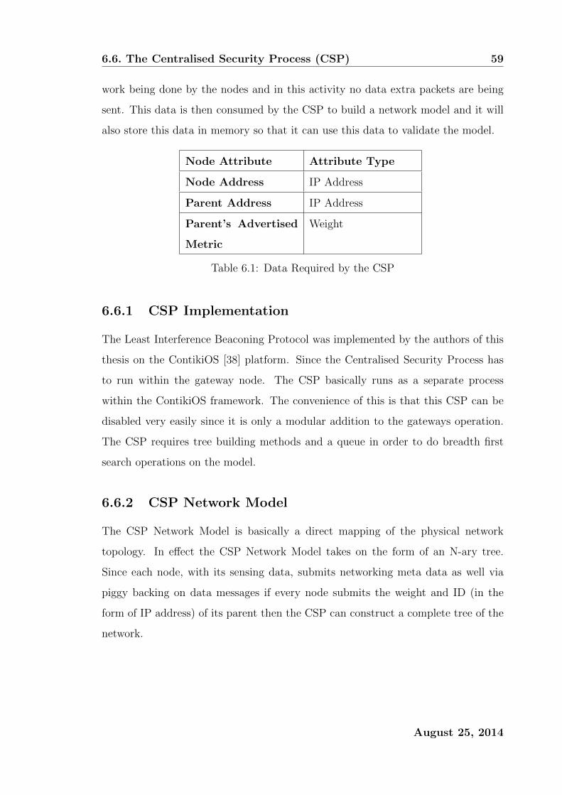
6.6. The Centralised Security Process (CSP) 59
work being done by the nodes and in this activity no data extra packets are being
sent. This data is then consumed by the CSP to build a network model and it will
also store this data in memory so that it can use this data to validate the model.
Node Attribute Attribute Type
Node Address IP Address
Parent Address IP Address
Parent’s Advertised
Metric
Weight
Table 6.1: Data Required by the CSP
6.6.1 CSP Implementation
The Least Interference Beaconing Protocol was implemented by the authors of this
thesis on the ContikiOS [38] platform. Since the Centralised Security Process has
to run within the gateway node. The CSP basically runs as a separate process
within the ContikiOS framework. The convenience of this is that this CSP can be
disabled very easily since it is only a modular addition to the gateways operation.
The CSP requires tree building methods and a queue in order to do breadth first
search operations on the model.
6.6.2 CSP Network Model
The CSP Network Model is basically a direct mapping of the physical network
topology. In effect the CSP Network Model takes on the form of an N-ary tree.
Since each node, with its sensing data, submits networking meta data as well via
piggy backing on data messages if every node submits the weight and ID (in the
form of IP address) of its parent then the CSP can construct a complete tree of the
network.
August 25, 2014

6.6. The Centralised Security Process (CSP) 60
Figure 6.2: (a) in-memory model (b) live network topology
In figure 6.2 above, the in-memory model is the tree representation of the live
network topology. Sometimes the model may not visually map map onto the live
topology, the tree as a set of edges and vertices is exactly the same as the live
network topology. It is possible to build this model since from each node the CSP
is given information about the node, its parent, and its parent’s weight, which gives
us two vertices with the directed edge and the edge’s weight (in this thesis referred
to as the link metric).
6.6.3 CSP Sinkhole Detection
Once the CSP has built up the network model it can do various checks on the
network one of which is sink-hole detection. Recall that the gateway running the
CSP has collected information regarding the network over a period of time thus the
CSP has a relatively good model on the network and where the traffic should be
flowing given that the network is a tree-like where the data flows upwards towards
the sink. The CSP with its model can calculate the amount of children each parent
is supporting by running a breadth first search on the CSP Network Model. The
breadth first search will give you, for a given node in the model, what the link metric
it should be reporting. The CSP then cross checks the calculated link metric against
the link metric that was reported by one of its children. If a node has no link metric
reported for it then that means that the particular node has to be a leaf node.
August 25, 2014

6.6. The Centralised Security Process (CSP) 61
Data: N-ary tree populated with advertised node data
Data: List of advertised weights of each node
Result: Possible candidate of sink-hole
Push root of tree onto queue
Mark root as being visited
while queue is not empty doPop top element off queue into p
c = first child of p
kids = 0
while c has not been visited doPush c into queue
Mark c as being visited
kids++
c = next sibling of c
end
Mark c with calculated variable kids
if advertised weight of c is less than kids of c thenc is a sink-hole
end
end
Figure 6.3: BFS Algorithm for Sinkhole Detection
Figure 6.4: Sinkhole Detection Visualised
August 25, 2014
6.7. Testing and Experiment Methodology 62
6.6.4 CSP Sinkhole Reaction
In order to decrease false positives to sink-holes, the CSP will need to run a rudi-
mentary consistency check of the model against the most recent network traffic
meta-data collected. If the CSP recognises a sink-hole in the detection phase, then
the CSP will immediately broadcast a security beacon holds the information about
what sort of attack the beacon is classified for and what the ID of the offending node
in the network is. For each node with the offending node in their neighbour list,
the node will penalise the offending node thus removing the penalised node from
being potentially selected as a future parent. The security beacon is a normal type
of beacon except these packets are prioritised. In the case of LIBP which is built on
top of the RIME [16] communications protocol, the security beacon is placed on the
messaging queue with a high priority which prompts the underlying communications
interface to broadcast the security beacon as soon as possible.
6.7 Testing and Experiment Methodology
Testing Environment - These experiments will be conducted on the Contiki
platform. The mote that will be emulated in Cooja [39] for this experiment will be
the Tmote sky mote. In the case that emulation is not required; Cooja motes will
be used for simulation. The experiment will be conducted in Contikis simulation
environment called Cooja.
Data Collection - Metrics in the experiment were collected by implementing
the energest (energy estimation) module in Contiki [19]. Energest is used for ob-
taining a per-component or per-node power consumption value. Cooja also has an
online data collection application called the shell collect view. The shell collect view
gives a comprehensive breakdown of node specific status variables and meta-data.
August 25, 2014

6.8. Results and Evaluation 63
Number of Nodes In
Network
Variable between 50 and 140
Topology 300mx300m
Mote Tmote Sky
Beacon Interval 30 seconds (LIBP)
Messaging Interval 30 seconds
Message Contents Hello from node
Simulation Runtime 10 minutes
Location of Base Station (0,0)
Location of Sinkhole Varying depending on experiment
TX/INT Range 50m/100m
Table 6.2: Parameters for experiment
Testing Methodology - The table above outlines the experiment runtime. In
short, unless otherwise specified, the networks are each given a 2 minute period to
allow for the network to settle; thereafter the network is run for 8 minutes to give a
total simulation runtime of 10 minutes. Each node will periodically send a packet
containing the string Hello from node as its packet data. Since each node is given
8 minutes to send the data at a period of 30 seconds, the nodes will each send 16
packets data to be collected by the sink. For each experiment run, 4 marked nodes
will be placed within the topology, as the simulation time progresses at the following
times a node will behave as if it is a sink-hole 2,4,6,8 minute marks For the various
experiments, all of Coojas existing profiling tools were used as experimentation tools.
Simulation timers and node real-time timers were used as experimentation tools for
time sensitive experiments.
6.8 Results and Evaluation
The impact of the CSP implementation will be observed against a non-CSP imple-
mentation in terms of energy. The CSP will also be assessed in terms of how fast
it is at detecting and reacting to a sink-hole. The CSP will also be assessed on
August 25, 2014

6.8. Results and Evaluation 64
how long it takes for a sink-hole to be excluded from the network from the time the
sink-hole had network presence.
6.8.1 Accuracy of Sinkhole Detection
50 60 70 80 90 100 110 120 130 14090
92
94
96
98
100
Topology Size
Succ
ess
Rat
e(%
)Success Rate of Sinkhole Detection
Figure 6.5: The topology size vs success rate
Figure 6.5 shows the success rate of the CSP per topology size. The success rate is
100% for topologies of reasonable sizes however the accuracy drops off towards the
copiously large topologies of 120 nodes and larger. The reasons for this could be
due to noise, congested nodes, or dropped packets.
August 25, 2014
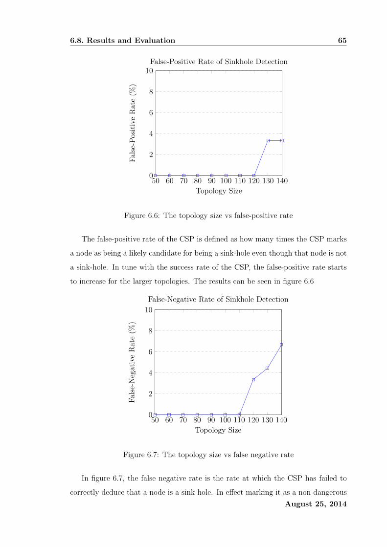
6.8. Results and Evaluation 65
50 60 70 80 90 100 110 120 130 1400
2
4
6
8
10
Topology Size
Fal
se-P
osit
ive
Rat
e(%
)
False-Positive Rate of Sinkhole Detection
Figure 6.6: The topology size vs false-positive rate
The false-positive rate of the CSP is defined as how many times the CSP marks
a node as being a likely candidate for being a sink-hole even though that node is not
a sink-hole. In tune with the success rate of the CSP, the false-positive rate starts
to increase for the larger topologies. The results can be seen in figure 6.6
50 60 70 80 90 100 110 120 130 1400
2
4
6
8
10
Topology Size
Fal
se-N
egat
ive
Rat
e(%
)
False-Negative Rate of Sinkhole Detection
Figure 6.7: The topology size vs false negative rate
In figure 6.7, the false negative rate is the rate at which the CSP has failed to
correctly deduce that a node is a sink-hole. In effect marking it as a non-dangerous
August 25, 2014
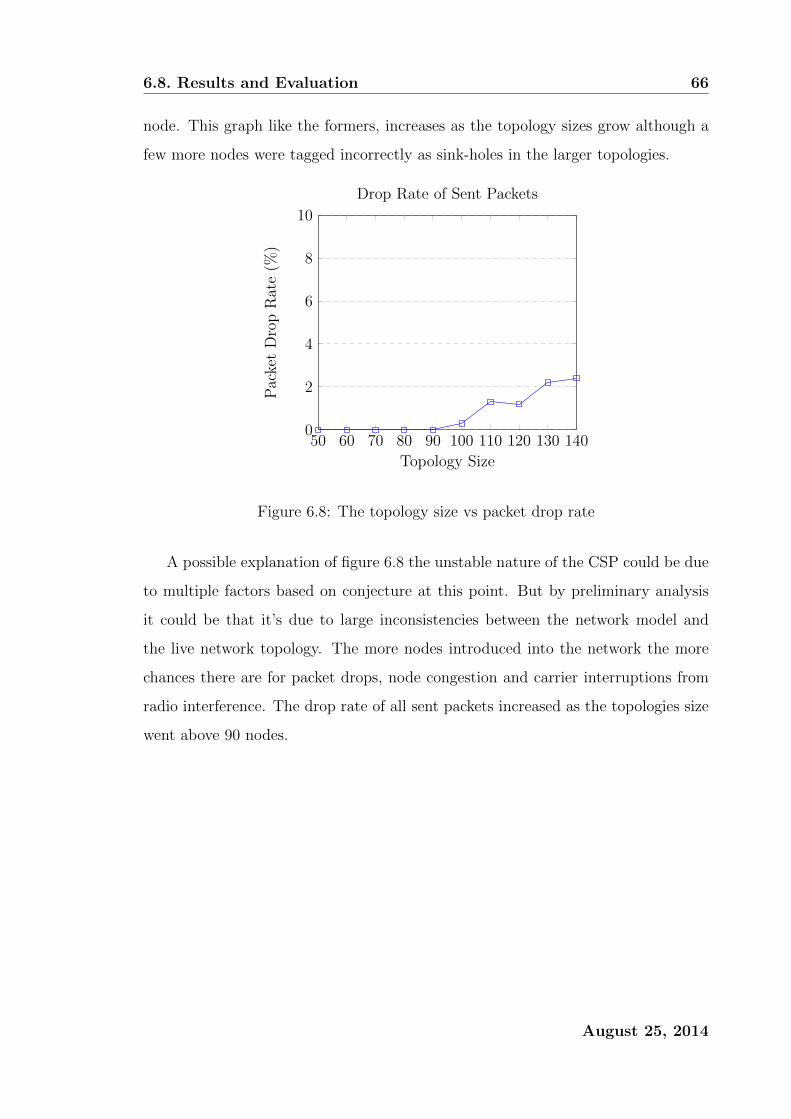
6.8. Results and Evaluation 66
node. This graph like the formers, increases as the topology sizes grow although a
few more nodes were tagged incorrectly as sink-holes in the larger topologies.
50 60 70 80 90 100 110 120 130 1400
2
4
6
8
10
Topology Size
Pac
ket
Dro
pR
ate
(%)
Drop Rate of Sent Packets
Figure 6.8: The topology size vs packet drop rate
A possible explanation of figure 6.8 the unstable nature of the CSP could be due
to multiple factors based on conjecture at this point. But by preliminary analysis
it could be that it’s due to large inconsistencies between the network model and
the live network topology. The more nodes introduced into the network the more
chances there are for packet drops, node congestion and carrier interruptions from
radio interference. The drop rate of all sent packets increased as the topologies size
went above 90 nodes.
August 25, 2014
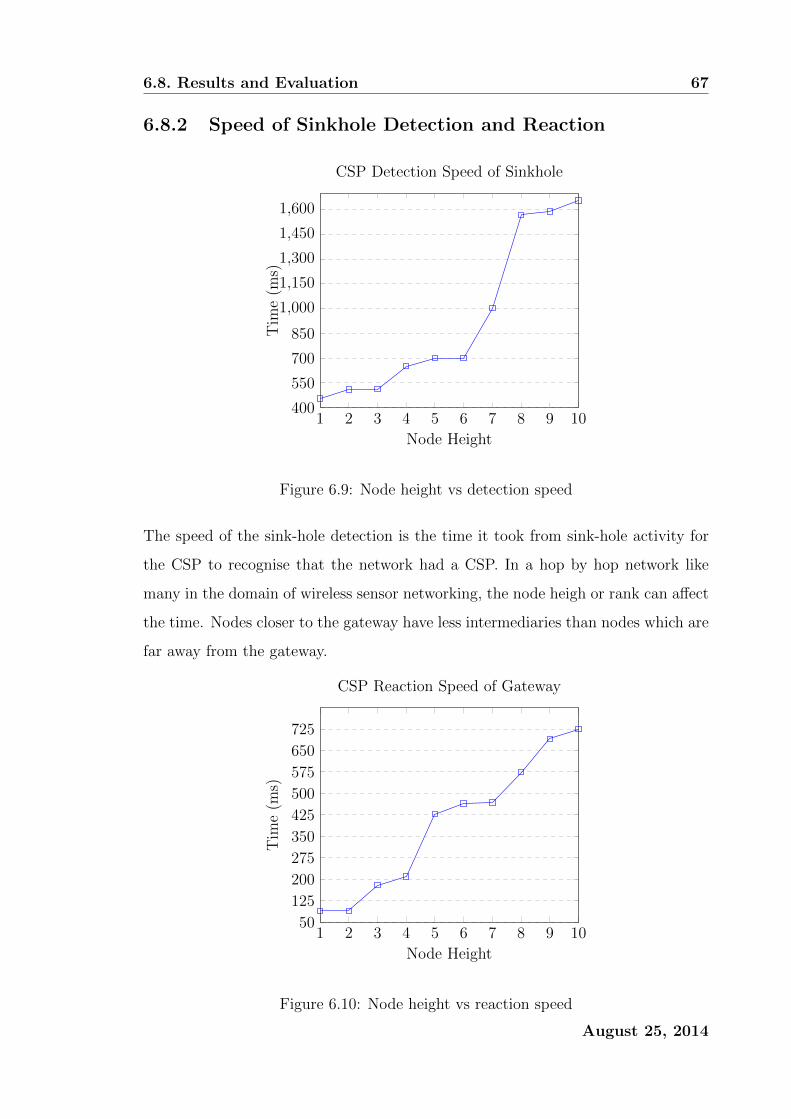
6.8. Results and Evaluation 67
6.8.2 Speed of Sinkhole Detection and Reaction
1 2 3 4 5 6 7 8 9 10400
550
700
850
1,000
1,150
1,300
1,450
1,600
Node Height
Tim
e(m
s)
CSP Detection Speed of Sinkhole
Figure 6.9: Node height vs detection speed
The speed of the sink-hole detection is the time it took from sink-hole activity for
the CSP to recognise that the network had a CSP. In a hop by hop network like
many in the domain of wireless sensor networking, the node heigh or rank can affect
the time. Nodes closer to the gateway have less intermediaries than nodes which are
far away from the gateway.
1 2 3 4 5 6 7 8 9 1050
125
200
275
350
425
500
575
650
725
Node Height
Tim
e(m
s)
CSP Reaction Speed of Gateway
Figure 6.10: Node height vs reaction speed
August 25, 2014

6.8. Results and Evaluation 68
The CSP reaction speed of the gateway per node height is the time it takes for
the gateway to send out the security beacons to the affected areas. This graph in a
way shows the reverse of the CSP Detection speed graph, the only major difference
is, since these security beacons are prioritised, they travel much quicker than normal
data packets.
1 2 3 4 5 6 7 8 9 10500
725
950
1,175
1,400
1,625
1,850
2,075
2,300
2,525
Node Height
Tim
e(m
s)CSP Speed of Problem Resolution
Figure 6.11: Node height vs problem resolution speed
The CSP speed of problem resolution is the time it takes for a sink-hole from it
being present in the network until the sink-hole is excluded in the sink-holes local
network by penalty from the security beacons.
6.8.3 Overhead Cost of The CSP
The overhead cost of the CSP were obtained by running a host of Tmote Sky mote
in an emulation environment which gives can serve up estimates on energy usage.
CSP Non-CSP
3.901 3.866
Table 6.3: Average Power Consumption (mW)
This is the average power consumption for the nodes in topology size 50.
August 25, 2014

6.9. Analysis, and Conclusion 69
CSP Non-CSP
2.841 2.643
Table 6.4: Gateway Power Consumption (mW)
The power consumption of a gateway running CSP is marginally higher than
that of a gateway not running the CSP. The only major addition the CSP adds is
the requirement for memory for the network model and packet historical data.
CSP Non-CSP
1.983 2.822
Table 6.5: Energy Usage of Sinkhole (mW)
In the case of no CSP being implemented. The sink-hole, due to many radio
TX/RX operations can use up far more energy then usual. A sink-hole attack in
the case of node capture could mean that not only does the attacker have access
to WSN information, but the attacker can also deplete the captured node of its
stored energy quicker since that node acting as a sink-hole will be inundated with
communications from other nodes.
6.9 Analysis, and Conclusion
The CSP presents a novel and simple way of dealing with a very easy to launch
network penetration attack like the sink-hole attack. This thesis chapter presented
the CSP, a process which relies on distributed information to perform a security
check over the network. The CSP has shown that a modular addition to a unsecured
routing protocol can help make wireless sensor network deployments more secure.
The experiments tested the accuracy of the CSP and its impact from an energy
standpoint on the network, the CSP was also tested on its speed in detection and
reaction. The CSP’s weakness is that it suffers from not being able to perform
accurately when the network is under major stress in terms of network traffic. These
major stresses result in node congestion, which can result in dropped packets, and
August 25, 2014

6.9. Analysis, and Conclusion 70
there is the issue with carrier sense interference which can get worse the more dense
your topology gets.
August 25, 2014
Chapter 7
Discussion
This thesis involved the development, implementation, and experimentation of the
Least Interference Beaconing Protocol amongst other routing protocols, IEEE 802.15.4
MAC layer security, and the usage of a central security process. The combination
of these three components is used to bolster up the general level of security of a
constrained network deployment.
7.1 Threat Model
Eavesdropping - IEEE 802.15.4 provides full protection against eavesdropping as
long as the pre-shared key is not compromised as is the case for all other systems
that use cryptographic encryption. An eavesdropper without the security materials
required to decrypt messages cannot reveal the plain text.
Man-In-The-Middle Attack - In IEEE 802.15.4, the use of access control
lists (in any non-AES-CTR mode) implies the use of message authentication codes,
each packet will have the integrity of a message appended to it which protects against
Man-In-The-Middle (MIM) attacks.
Sinkhole Attacks - The presence of a sink-hole could be used as a data vac-
uum to aggregate data to a non-gateway node. A sink-hole can have monumental
affects. The Centralised Security Process (CSP) aims to minimise the proliferation
71

7.2. System Configurability 72
of sink-holes in a network.
Pre-Shared Keys - The pre shared keys are stored within the local IEEE
802.15.4 memory. In theory if a node is captured, the pre-shared key can be ob-
tained by aiming a pointer to the shared memory stack of the constrained device.
If the pre-shared key has been compromised then there could be a situation where
the constrained node could have collected previous messages and will then have the
ability to decrypt all these messages.
7.2 System Configurability
The composition of using a link metric based routing protocol with encryption means
that the routing control packets (control traffic) can be encrypted, along with the
data communication packets (data traffic). The benefit of having a system like this
is that there is a level of configurability in what packets should be encrypted de-
pending on the deployment requirements.
Data Encryption Control Encryption Protection Susceptibility Application
No No Rudimentary intru-
sion detection
Highly susceptible
to multiple security
breaches
Hobby deployment
Yes No Data integrity, confi-
dentiality ensures pro-
tection from eaves-
dropping
Susceptible to net-
work attacks, e.g.
wormhole attacks
Rural deployments
where sensed data is
medical or private
No Yes Network attacks Eavesdropping Backbone networks
Yes Yes Network attacks and
eavesdropping
Least susceptible to
the attacks
Critical industry de-
ployments (e.g. med-
ical or military indus-
tries)
Table 7.1: Data Required by the CSP
Table 7.1 shows that depending on the deployment application, one can configure
August 25, 2014

7.2. System Configurability 73
the deployment to use confidentiality on either the data traffic or on the control
traffic or a combination of both. Each use case provides a level of security that suits
a use case. In the case that neither control nor data traffic is being encrypted, then
there is only rudimentary intrusion detection from virtue of the centralised security
process and since that functionality is also configurable (by toggle) it could mean
that if the CSP is off then the network is totally susceptible to the whole spectrum
of security attacks that exist in constrained networks.
Following that use case is the configuration where the data plane traffic is encrypted
but the control plane traffic is left unencrypted. In such a deployment the only
guarantees that can be asserted are that eavesdroppers cannot readily sniff data
packets from the nodes within the network, however eavesdroppers can still sniff
network control plane traffic and infer statistics about the network based on the
traffic control data. This configuration is susceptible to attacks on the topology of
the network, breaks in the network can occur or wormhole attacks can be constructed
since the network control traffic data for the routing protocol can be forged by
an adversary. This configuration would suit applications where there is low risk
of intruders in an unattended deployment, however, the deployment requires that
the collected data is infarct sensitive to eavesdropping, one such example of this
deployment is one dude in a rural location where the data collected is medical
patient data.
In the third deployment use case the data plane traffic is left unencrypted where
as the control traffic data is encrypted. This means that the network topology and
routing protocol less susceptible to attacks that go for the routing packets. This is
because that these packets can’t be forged or faked by an advisory who’s trying to
deny service or break the networks’ routing table.
August 25, 2014

7.3. Known Issues 74
Figure 7.1: Linking two WSN groups to a gateway via a backbone network
Since the data traffic is unencrypted it is open to eavesdropping and packet
forgery, however if the packets are encrypted on the application level then this sort
of deployment is very suitable for backbone networks where the nodes operating
under this configuration are just forwarding packets from an island of sensors to a
gateway node as seen in figure 7.1.
The fourth and final deployment configuration is the most secure configuration es-
pecially if coupled with the centralised security process.
7.3 Known Issues
Centralised Security Process with IEEE 802.15.4 - The use of the cen-
tralised security with IEEE 802.15.4 can be more detrimental if used without any
form of control plane traffic encryption. The Centralised Security Process (CSP)
delivers its control packets as mandated by it’s deployment configuration. If these
packets are delivered unencrypted and un-identifiable, these packets can be forged
or subjected to man-in-the-middle (MIM) attacks. A situation where an adversary
node in the network can arise, where the adversary can orchestrate the network in
August 25, 2014
7.4. Future Implementations 75
such the way that the control packets can be constructed and made to look like they
came from the CSP node, this could result in a broken network or the penalising of
nodes un-justifiably.
Maximum Hop Length From Gateway - The Least Interference Beaconing
Protocol works by periodic beaconing as initiated by the gateway node at the start
of the networks’ deployment. IEEE 802.15.4 allows for TTLmax to be set within its
packet structure, however in preliminary experimentation, it was discovered that the
further the node is away from the CSP/LIBP gateway node the more inconsistencies
in behaviour that may arise in the network. In LIBP, if a node is alive in a network
but has yet to receive its initial beaconing control packet, it may be seen as a network
intruder. This is because the ACL is constructed during this network settling period.
CSP Race Condition With LIBP - Because of the way that packets are
sent within the framework of Contiki [15] and Rime [16]. A packet could be queued
to be sent to an adversary sink-hole node even if the the sender node has been
notified that its parent is a sink-hole and should be penalised in its LIBPneighbour
list. However since the packet has been queued it will be sent automatically by the
Contiki packet buffer management system. This could result in a few packets being
sent to the sink-hole even after the fact that the node has been notified that the
sink-hole is infact present.
7.4 Future Implementations
End-End encryption - An IPSec style end-end encryption is a desirable addition
to this thesis implementation. Having uninterrupted protection of communications
data transferring between two communicating parties, in a constrained network this
being the sensor node and the gateway node. This would typically be achieved by
encrypting the data on the application layer of the OSI model.
Protocol Versioning - At some level it would be beneficial to have protocol ver-
sioning for future versions to make sure that all nodes within the constrained network
August 25, 2014

7.4. Future Implementations 76
can adhere to the same protocol verion of LIBP or CSP.
August 25, 2014

Chapter 8
Conclusion
The over arching goal of this thesis was to evaluate the validity of a body of security
methods and how they could be combined in a constrained network or environment
of lightweight devices. We gave an overview of the security threats present in this
environment, and outlined the separate modular security mechanisms that could be
used in order to further secure these types of networks.
This thesis presented an evaluation of the validity of the Least Interference Beacon-
ing Protocol (LIBP) versus other constrained network routing protocols, Routing
Protocol for LLNs (RPL), and Collection Tree Protocol (CTP).
We also presented a comprehensive survey about what IEEE 802.15.4 had to offer
for constrained networks, with both its faults and merits we discussed certain pitfalls
that exist in the medium access control specification. We also showed its perfor-
mance under ideal conditions which can serve as a baseline for future researchers to
compare results with.
We then presented an intrusion detection system that hinges on the high compu-
tational power that gateways usually have. The intrusion detection system used a
naive approach to trying to monitor the network to catch sink-hole attacks. In its
implementation this intrusion detection system basically was a modular addition to
the routing protocol developed in this thesis (LIBP).
As a first step towards securing the constrained environment, we implemented
77

Chapter 8. Conclusion 78
a routing protocol called LIBP to address the issue of network availability since
network downtime is a security issue. We did a comprehensive study showing the
merits of LIBP versus the other routing protocols (CTP and RPL) by doing a wide
performance evaluation of these protocols. After addressing network availability
we realised that the next step would be to secure communications between nodes.
While many lightweight application level encryption algorithms existed, we opted for
AES which are (usually) implemented in hardware on the IEEE 802.15.4 compliant
radio chips. Also for interoperability making this choice was for the best since many
other network specifications are built on top of IEEE 802.15.4. We saw the flaws
of 802.15.4 from a security standpoint and presented a few feasible workarounds
however not desirable. Once communications encryption was complete, we moved
onto adding a ”real-time” intrusion detection system for sink hole attacks. We
showed how accurate it was and how fast the intrusion detection system was to
react to sink-holes in the network. We also showed that our intrusion detection
worked best when packet loss was minimal.
August 25, 2014
References
[1] J.-P. Vasseur and A. Dunkels, Interconnecting smart objects with ip: The next
internet. Morgan Kaufmann, 2010.
[2] K. Stammberger, M. Semp, M. Anand, and D. Culler, “Introduction to security
for smart object networks,” IPSO Alliance, 2010.
[3] A. Bagula, D. Djenouri, E. Mouatez, and B. Karbab, “Least Interference Bea-
coning : A New Ubiquitous Sensor Network Management Model,”
[4] O. Gnawali, R. Fonseca, K. Jamieson, D. Moss, and P. Levis, “Collection Tree
Protocol,” 2009.
[5] T. Winter, P. Thubert, A. R. Corporation, and R. Kelsey, “RPL: IPv6 Routing
Protocol for Low-Power and Lossy Networks,” pp. 1–158.
[6] O. Garcia-Morchon, S. Kumar, R. Struik, S. Keoh, and R. Hummen, “Security
considerations in the ip-based internet of things,” 2013.
[7] J. Y. Khan, M. R. Yuce, and F. Karami, “Performance evaluation of a wireless
body area sensor network for remote patient monitoring,” in Engineering in
Medicine and Biology Society, 2008. EMBS 2008. 30th Annual International
Conference of the IEEE, pp. 1266–1269, IEEE, 2008.
[8] M. Saraogi, “Security in wireless sensor networks,” pp. 1–12.
[9] L. Ngqakaza and A. Bagula, “On the relevance of using a multi-layered security
protocol in the internet-of-the-things,” (East London, South Africa), 2013.
79
REFERENCES 80
[10] L. Ngqakaza and A. Bagula, “Least path interference beaconing protocol (libp):
A frugal protocol for the internet-of-things,” (Paris, France), 2014.
[11] J. P. Vasseur, C. Fellow, C. Systems, J. Hui, S. Engineer, Z. Shelby, C. Nerd,
P. Bertrand, W. Sas, and C. Chauvenet, “power and lossy networks,” no. April,
2011.
[12] A. Bagula, D. Djenouri, and E. Karbab, “Ubiquitous sensor network manage-
ment: The least interference beaconing model,” 2013 IEEE 24th Annual Inter-
national Symposium on Personal, Indoor, and Mobile Radio Communications
(PIMRC), pp. 2352–2356, Sept. 2013.
[13] B. Antoine, D. Djenouri, and E. Karbab, “On the relevance of using interference
and service differentiation routing in the internet-of-things,” 2013.
[14] P. Levis, N. Lee, M. Welsh, and D. Culler, “Tossim: Accurate and scalable
simulation of entire tinyos applications,” in Proceedings of the 1st international
conference on Embedded networked sensor systems, pp. 126–137, ACM, 2003.
[15] a. Dunkels, B. Gronvall, and T. Voigt, “Contiki - a lightweight and flexible
operating system for tiny networked sensors,” 29th Annual IEEE International
Conference on Local Computer Networks, pp. 455–462.
[16] A. Dunkels, “Poster Abstract : Rime A Lightweight Layered Communication
Stack for Sensor Networks,”
[17] P. A. Levis, N. Patel, D. Culler, and S. Shenker, Trickle: A self regulating
algorithm for code propagation and maintenance in wireless sensor networks.
Computer Science Division, University of California, 2003.
[18] P. Thubert, “Objective function zero for the routing protocol for low-power and
lossy networks (rpl),” 2012.
[19] A. Dunkels, F. Osterlind, N. Tsiftes, and Z. He, “Software-based on-line energy
estimation for sensor nodes,” in Proceedings of the 4th workshop on Embedded
networked sensors, pp. 28–32, ACM, 2007.
August 25, 2014
REFERENCES 81
[20] J. Zheng and M. J. Lee, “A comprehensive performance study of ieee 802.15.
4,” 2004.
[21] N. Sastry and D. Wagner, “Security considerations for IEEE 802.15.4 net-
works,” Proceedings of the 2004 ACM workshop on Wireless security - WiSe
’04, p. 32, 2004.
[22] M. S. Siddiqui and C. S. Hong, “Security Issues in Wireless Mesh Networks,”
2007.
[23] E. C. Ngai, J. Liu, and M. R. Lyu, “An efficient intruder detection algorithm
against sinkhole attacks in wireless sensor networks,” Computer Communica-
tions, vol. 30, pp. 2353–2364, Sept. 2007.
[24] A. A. Pirzada and C. McDonald, “Advanced Wired and Wireless Networks,”
Book, vol. 24, pp. 561–570, Oct. 2004.
[25] I. Krontiris, T. Giannetsos, and T. Dimitriou, “Launching a Sinkhole Attack in
Wireless Sensor Networks; The Intruder Side,” 2008 IEEE International Con-
ference on Wireless and Mobile Computing, Networking and Communications,
pp. 526–531, Oct. 2008.
[26] U. S. Rajkumar and R. Vayanaperumal, “a Leader Based Monitoring Approach
for Sinkhole Attack in Wireless Sensor Network,” Journal of Computer Science,
vol. 9, pp. 1106–1116, Sept. 2013.
[27] G. Kim, Y. Han, and S. Kim, “A cooperative-sinkhole detection method for
mobile ad hoc networks,” AEU - International Journal of Electronics and Com-
munications, vol. 64, pp. 390–397, May 2010.
[28] W. Shim, G. Kim, and S. Kim, “A distributed sinkhole detection method using
cluster analysis,” Expert Systems with Applications, vol. 37, pp. 8486–8491,
Dec. 2010.
[29] S. Hamedheidari and R. Rafeh, “A novel agent-based approach to detect sink-
hole attacks inwireless sensor networks,” Computers & Security, vol. 37, pp. 1–
14, Sept. 2013.
August 25, 2014
REFERENCES 82
[30] H. C. Tseng and B. J. Culpepper, “Sinkhole intrusion in mobile ad hoc net-
works: The problem and some detection indicators,” Computers & Security,
vol. 24, pp. 561–570, Oct. 2005.
[31] H. Al Nahas, J. S. Deogun, and E. D. Manley, “Proactive mitigation of impact
of wormholes and sinkholes on routing security in energy-efficient wireless sensor
networks,” Wireless Networks, vol. 15, pp. 431–441, Aug. 2007.
[32] N. Sreelaja and G. Vijayalakshmi Pai, “Swarm intelligence based approach for
sinkhole attack detection in wireless sensor networks,” Applied Soft Computing,
vol. 19, pp. 68–79, June 2014.
[33] C. Karlof and D. Wagner, “Secure routing in wireless sensor networks: attacks
and countermeasures,” Proceedings of the First IEEE International Workshop
on Sensor Network Protocols and Applications, 2003., pp. 113–127, 2003.
[34] Pirzada, “Trust models in wireless sensor networks,” in Recent Trends in Net-
work Security and Applications, pp. 39–42, CNSA, 2010.
[35] C. Karlof and D. Wagner, “Secure routing in wireless sensor networks: attacks
and countermeasures,” Proceedings of the First IEEE International Workshop
on Sensor Network Protocols and Applications, 2003., pp. 113–127, 2003.
[36] H. Al Nahas, J. S. Deogun, and E. D. Manley, “Proactive mitigation of impact
of wormholes and sinkholes on routing security in energy-efficient wireless sensor
networks,” Wireless Networks, vol. 15, pp. 431–441, Aug. 2007.
[37] E. C. Ngai, J. Liu, and M. R. Lyu, “An efficient intruder detection algorithm
against sinkhole attacks in wireless sensor networks,” Computer Communica-
tions, vol. 30, pp. 2353–2364, Sept. 2007.
[38] A. Dunkels, “The contiki os.”
[39] J. Eriksson, F. Osterlind, N. Finne, N. Tsiftes, A. Dunkels, T. Voigt, R. Sauter,
and P. J. Marron, “Cooja/mspsim: interoperability testing for wireless sensor
networks,” in Proceedings of the 2nd International Conference on Simulation
August 25, 2014

REFERENCES 83
Tools and Techniques, p. 27, ICST (Institute for Computer Sciences, Social-
Informatics and Telecommunications Engineering), 2009.
August 25, 2014

84
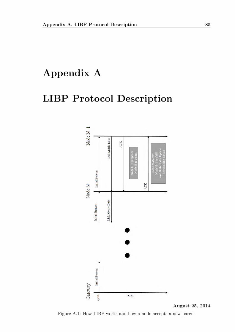
Appendix A. LIBP Protocol Description 85
Appendix A
LIBP Protocol Description
Figure A.1: How LIBP works and how a node accepts a new parent
August 25, 2014
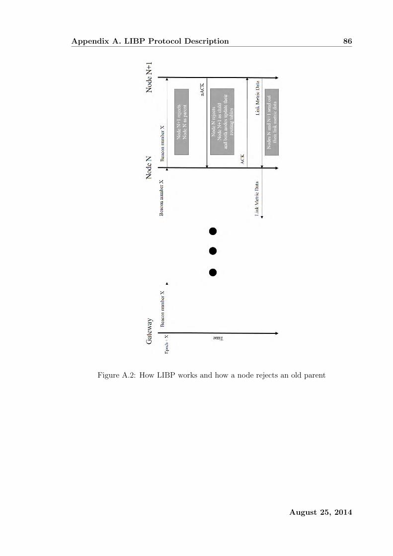
Appendix A. LIBP Protocol Description 86
Figure A.2: How LIBP works and how a node rejects an old parent
August 25, 2014

Appendix B
Least Interferance Beaconing API
Documentation
Source code for LIBP can be found at https://github.com/Lutando/libp. These
API docs can help you navigate through the code quicker.
When the word term link metric is used, this is also the same as the link weight
or in the context of the Least Interferance Beaconing Protocol this is the number of
supporting children.
B.1 LIBP
This is the documentation that describes libp.c and libp.h
void libp open()
Opens the broadcast and unicast connections for LIBP.
void libp close()
Closes the broadcast and unicast connections for LIBP.
void libp send()
Sends a data packet with sensor data or otherwise to be queued by the Contiki
packetbuffer framework.
87

B.2. LIBP Link Metric 88
void libp set sink()
Used on only the sink node usually this node has an address of 0 or 1.
void libp set beacon period()
Sets the beacon period (in milliseconds).
B.2 LIBP Link Metric
This is the documentation that describes libp-link-metric.c and libp-link-metric.h
void libp link metric new()
Initialises a new link metric.
uint16 t libp link metric()
Computes the link metric for the given link.
B.3 LIBP Neighbour
This is the documentation that describes libp-neighbour.c and libp-neighbour.h
void libp neighbour init()
Allocates memory for the LIBPneighbour struct.
libp neighbour list add()
Adds a new member to the LIBPneighbour list.
libp neighbour list remove()
Removes a member from the LIBPneighbour list.
struct libp neighbour *libp neighbour list find()
August 25, 2014
B.3. LIBP Neighbour 89
Finds a specific member from the LIBPneighbour list.
struct libp neighbour *libp neighbour list best()
Finds the best LIBPneighbour for parent selection.
int libp neighbour list num()
Returns the size of the LIBPneighbour list.
uint16 t libp neighbour link metric()
Returns the link metric of a specific LIBPneighbour.
August 25, 2014