multi-layered ring log-periodic antennas array design for gps systems
TRANSCRIPT
7/31/2019 Multi-Layered Ring Log-Periodic Antennas Array Design for GPS Systems
http://slidepdf.com/reader/full/multi-layered-ring-log-periodic-antennas-array-design-for-gps-systems 1/12
7/31/2019 Multi-Layered Ring Log-Periodic Antennas Array Design for GPS Systems
http://slidepdf.com/reader/full/multi-layered-ring-log-periodic-antennas-array-design-for-gps-systems 2/12
International Journal of Computer Networks & Communications (IJCNC) Vol.4, No.3, May 2012
82
frequency piloting or polarization …etc. But we also must seek smallest and low cost antennas
(we have little place on a mobile terminal) we must have the possibility to integrate
components easily in order to ensure other electronic functions. Moreover, the antennascharacteristics must remain not very influenceable by the environment.
Frequently, circular polarization is used. Circular polarization is most often use on satellitecommunications. This is particularly desired since the polarization of a linear polarized radio
wave may be rotated as the signal passes through any anomalies (such as Faraday rotation) in
the ionosphere. Furthermore, due to the position of the Earth with respect to the satellite,
geometric differences may vary especially if the satellite appears to move with respect to the
fixed Earth bound station. Circular polarization will keep the signal constant regardless of these anomalies. In addition, antennas with circular polarization radiation have found wide
applications in mobile satellite communications and direct satellite broadcasting systems due to
their insensivity to the ionospheric polarization rotation. Many types of microstrip antennas
have been proposed and investigated [1-3].
Many antennas use a wide frequency range, from this log-periodic antennas. They are multipleelement antennas whose length and the gap between the components is increasing steadily in
geometrical progression.
From what has been discussed, this work focuses on the study of a multilayered ring printed
antennas array in log periodic arrangement.
2. DESIGN PROCEDURE
For the development of this array, two procedures were used. The first is to develop the feed
circuit (Figure 1) and the second to associate it with the ring antenna in log-periodic architecture.
2.1. Feed circuit
The reason that a circularized array can be constructed by linearly polarized elements is
primarily attributed to a four-element sub-array with unique angular and phase arrangements.
This basic sub-array has its elements arranged in a 2×2 square or rectangular grid configuration
with element angular orientation and feed phase arranged in either a 0°, 90°, 180°, 270°
fashion. An example that uses microstrip patches is illustrated in Figure 1. The purpose of
different angular orientations of the patches is to generate two orthogonally polarized fields,
while different feed phases are used to provide the required phase delays for CP generation. It
is well known that the circular polarization can be achieved in the broadside direction of an
array composed of two linearly polarized elements with angle and phase arranged in 0°, 90°
fashion as shown in Figure. 2(a). The CP in this arrangement, however, becomes very poor at
angles greater than 5° off broadside direction in the x-z plane. This is caused by the spatialdelay ( Ψ ’=k 0 x sin θ , see Figure 2 (b)) formed between the two orthogonally polarized
elements. This spatial delay, which disturbs the required 90° phase, contributes to the poor CP
quality at angles off broadside.

7/31/2019 Multi-Layered Ring Log-Periodic Antennas Array Design for GPS Systems
http://slidepdf.com/reader/full/multi-layered-ring-log-periodic-antennas-array-design-for-gps-systems 3/12
International Journal of Computer Networks & Communications (IJCNC) Vol.4, No.3, May 2012
83
Figure 1. 2×2 microstrip arrays that generate CP with LP elements.
(a) 0°, 90°, 0°, 90° arrangement for narrow-band application,(b) 0°, 90°, 180°, 270° arrangement for wide-band application
Figure 2. (a) Two-element microstrip array with 0°, 90°arrangement,
(b) Its spatial phase delay Ψ ’=k 0 x sin θ
In our case, the circular polarization is achieved by having a basic 2×2 sub-arrays with element
angular and phase arrangement, both the element orientation and feed phase are arranged in 0°,90°, 180°, 270° fashion. Thus, the feed network of the four elements of array is obtained by
using a coupler with four output terminals in order to obtain a circular polarization during
simulation, these circuits must present:
• A phase of 90° between two consecutive terminal port,
• An amplitude level of – 6 dB compared to the maximum on each terminal port,
y
x
z
Ψ=90º
x
z
x
Ψ’
θ
Ψ=0º
(a) (b)
Ψ=90
Ψ=0
Ψ=90
Ψ=0
Ψ=270
Ψ=180
Ψ=90Ψ=0
(a) (b)

7/31/2019 Multi-Layered Ring Log-Periodic Antennas Array Design for GPS Systems
http://slidepdf.com/reader/full/multi-layered-ring-log-periodic-antennas-array-design-for-gps-systems 4/12
International Journal of Comput
Where:
• Coupler –3 dB, 180° is selec
compact ring in order to redu
• A branch coupler - 3 dB, 90 °
amplitude and phase shifted
placed on one of the terminati
order to ensure good insulatio
The mask of the supply circuit
shown in Figure 3.
Figure 3. Diagr
The Mask layout of the right hand c
Figure 4. The Mask layout
Coupleur en
anneau
- 3 dB, 180°
Entrée Rat-race couplInput
Port 1, 5
Port 2
0 °, - 6 dB
50 ΩΩΩΩ
er Networks & Communications (IJCNC) Vol.4, No.3,
ted, in both cases, a Rat-race coupler of 4 termina
e its maximum size.
for dividing the incident signal into two output sign
by 90 ° with respect to each other. A matched lo
on ports in order to absorb the reflected signal by ea
n.
for the right hand circular polarization (RHCP) d
am block of the feed network for RHCP polarizatio
ircular polarization circuit generation is shown in fi
of the circuit for right hand circular polarization ge
Coupleur à
branches (1)
- 3 dB, 90°
Coupleur à
branches (2)
- 3 dB, 90°
- 3 dB, 0°
- 3 dB, 180°
- 6
- 6
- 6
-
0°
90°
0°
90°
Branch coupler
1
Branch coupler
2
r
ΩΩΩΩ
Port 5
270 °, - 6 dB
50 ΩΩΩΩ
Port 4
180 °, - 6 dB
50 ΩΩΩΩ
Port 3
90 °, - 6 dB
50 ΩΩΩΩ
ay 2012
84
l ports of a
als of same
ad must be
h output in
eveloped is
.
ure 4.
neration.
dB, 0°
B, 90°
dB, 180°
6 dB, 270°
7/31/2019 Multi-Layered Ring Log-Periodic Antennas Array Design for GPS Systems
http://slidepdf.com/reader/full/multi-layered-ring-log-periodic-antennas-array-design-for-gps-systems 5/12
International Journal of Computer Networks & Communications (IJCNC) Vol.4, No.3, May 2012
85
R2
R1
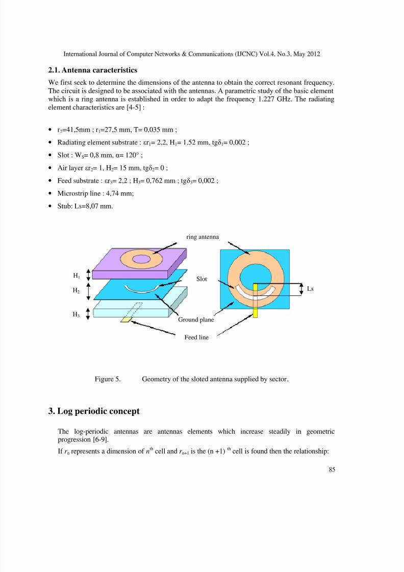
2.1. Antenna caracteristics
We first seek to determine the dimensions of the antenna to obtain the correct resonant frequency.
The circuit is designed to be associated with the antennas. A parametric study of the basic element
which is a ring antenna is established in order to adapt the frequency 1.227 GHz. The radiatingelement characteristics are [4-5] :
• r2=41,5mm ; r1=27,5 mm, T= 0,035 mm ;
• Radiating element substrate : εr1= 2,2, H1= 1.52 mm, tgδ1= 0,002 ;
• Slot : WS= 0,8 mm, α= 120° ;
• Air layer εr2= 1, H2= 15 mm, tgδ2= 0 ;
• Feed substrate : εr3= 2,2 ; H3= 0,762 mm ; tgδ3= 0,002 ;
• Microstrip line : 4,74 mm;
• Stub: Ls=8,07 mm.
Figure 5. Geometry of the sloted antenna supplied by sector.
3. Log periodic concept
The log-periodic antennas are antennas elements which increase steadily in geometricprogression [6-9].
If r n represents a dimension of nth cell and r n+1 is the (n +1) th cell is found then the relationship:
ring antenna
Slot
Ground plane
Feed line
Ls
H1
H2
H3
7/31/2019 Multi-Layered Ring Log-Periodic Antennas Array Design for GPS Systems
http://slidepdf.com/reader/full/multi-layered-ring-log-periodic-antennas-array-design-for-gps-systems 6/12
International Journal of Computer Networks & Communications (IJCNC) Vol.4, No.3, May 2012
86
n
1n
r
r +=τ (1)
Consequently, the arrays have the same properties of radiation at all frequencies which areconnected by the periodicity factor τ .
13
412
3121 f f ,f f ,f .f ,f τ=τ=τ= (2)
With:
It is noted that:
τ=τ= ln2
f
f ln;ln
f
f ln
1
3
1
2 (3)
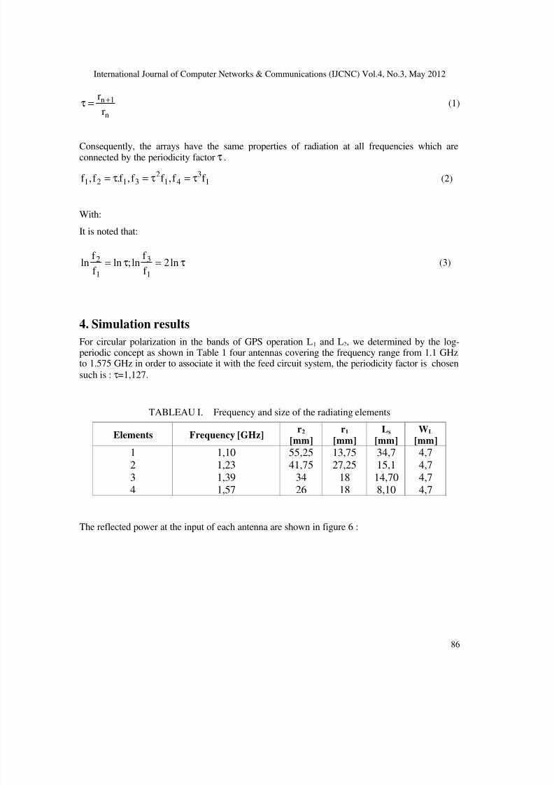
4. Simulation results
For circular polarization in the bands of GPS operation L1 and L2, we determined by the log-periodic concept as shown in Table 1 four antennas covering the frequency range from 1.1 GHzto 1.575 GHz in order to associate it with the feed circuit system, the periodicity factor is chosen
such is : τ=1,127.
TABLEAU I. Frequency and size of the radiating elements
Elements Frequency [GHz]r2
[mm]
r1
[mm] Ls
[mm] WL
[mm]
1
2
34
1,10
1,23
1,391,57
55,25
41,75
3426
13,75
27,25
1818
34,7
15,1
14,708,10
4,7
4,7
4,74,7
The reflected power at the input of each antenna are shown in figure 6 :
7/31/2019 Multi-Layered Ring Log-Periodic Antennas Array Design for GPS Systems
http://slidepdf.com/reader/full/multi-layered-ring-log-periodic-antennas-array-design-for-gps-systems 7/12
International Journal of Comput
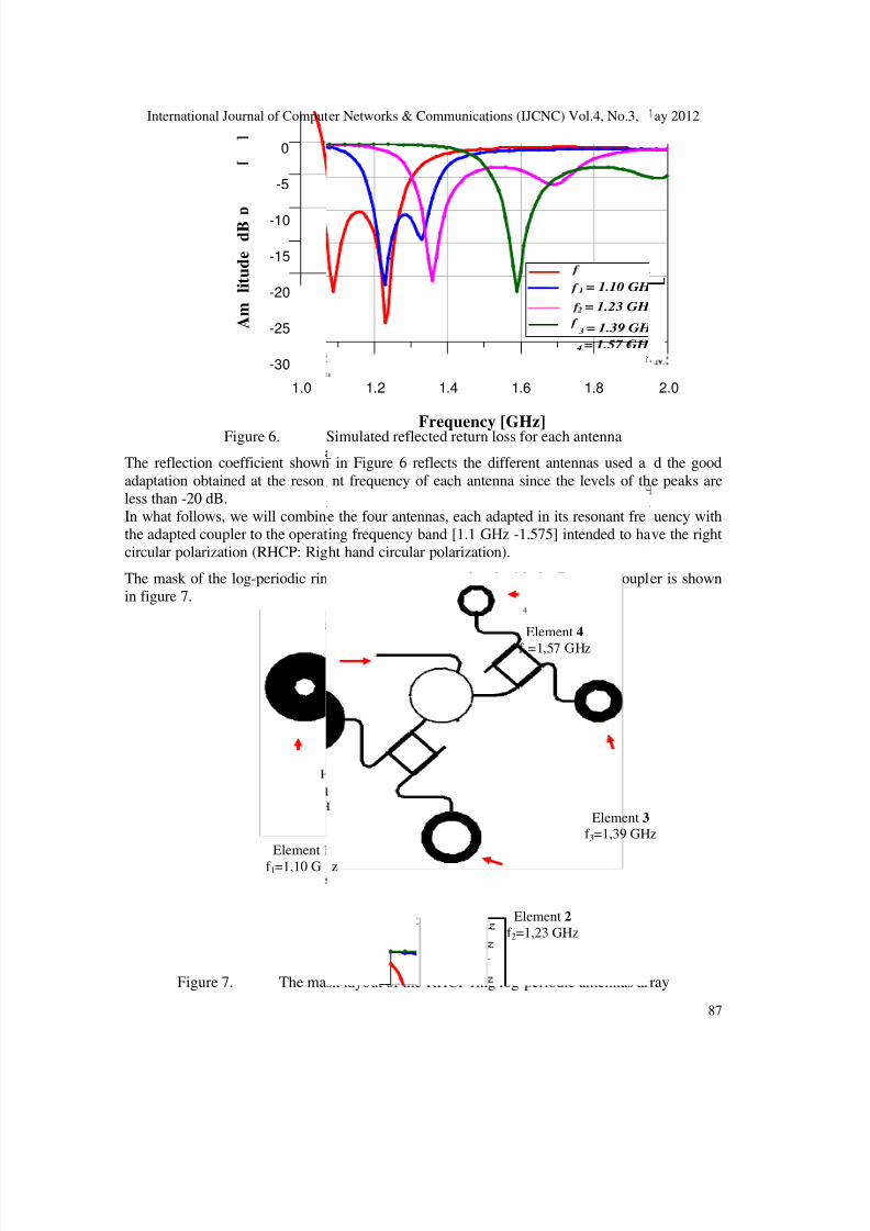
Figure 6.
The reflection coefficient shown
adaptation obtained at the reson
less than -20 dB.
In what follows, we will combin
the adapted coupler to the operat
circular polarization (RHCP: Rig
The mask of the log-periodic rin
in figure 7.
Figure 7. The ma
50
A m
l i t u d e
d B
1.0
-25
-20
-15
-10
-5
-30
0
Element 1
f 1=1,10 G
er Networks & Communications (IJCNC) Vol.4, No.3,
Simulated reflected return loss for each antenna
in Figure 6 reflects the different antennas used a
nt frequency of each antenna since the levels of th
e the four antennas, each adapted in its resonant fre
ing frequency band [1.1 GHz -1.575] intended to ha
ht hand circular polarization).
g antennas array associated with the Rat-race coupl
sk layout of the RHCP ring log-periodic antennas ar
Ω
Frequency [GHz]
1.2 1.4 1.6 1.8
3 = 1.39 GH
2 = 1.23 GH
1 = 1.10 GH
4 = 1.57 GH
Element 4
f =1,57 GHz
Element 3
f 3=1,39 GH
Element 2
f 2=1,23 GHz
z
ay 2012
87
d the good
e peaks are
uency with
ve the right
er is shown
ray
2.0
z
z

7/31/2019 Multi-Layered Ring Log-Periodic Antennas Array Design for GPS Systems
http://slidepdf.com/reader/full/multi-layered-ring-log-periodic-antennas-array-design-for-gps-systems 8/12
International Journal of Computer Networks & Communications (IJCNC) Vol.4, No.3, May 2012
88
The reflected return loss of the right circular polarization antennas array is shown in Figure 8 in
the band [1-1.8 GHz]. Notice from this figure, that the peak corresponds to the resonance
frequency in the band L2 is of about -19.46 dB with a band of 4.87%, and that whichcorresponds to the resonance frequency in the L1 band is of about -29.40 dB with a band of
8.11%. This confirms the good results obtained in terms of adaptation at the two band of GPSsystem operation.
Figure 8. Antennas array computed imput return
We present respectively in figure 9 and 10 the radiation patterns in three dimensions at the
frequency 1.227 GHz (L2) and at the frequency 1.575 GHz (L1).
Figure 9. Radiation pattern in 3D of the antennas array (f =1,227 GHz).
Frequency [GHz]
L2 L1
A
m p l i t u d e [ d B ]

7/31/2019 Multi-Layered Ring Log-Periodic Antennas Array Design for GPS Systems
http://slidepdf.com/reader/full/multi-layered-ring-log-periodic-antennas-array-design-for-gps-systems 9/12
International Journal of Computer Networks & Communications (IJCNC) Vol.4, No.3, May 2012
89
Figure 10. Radiation pattern in 3D of the antennas array (f =1,575 GHz).
In Figure 9, we note that the radiation patterns in both E and H planes are characterized by a
fairly good symmetry with respect to the direction θ = 0 ° with the maximum power points
towards this direction. The computed gain is 5.75 dB.
Notice from figure 10 and for the the first view, we note that the radiation patterns show an
asymmetry with respect to the direction θ = 0 °, the radiation pattern is characterized by a wavy
lobes whose amplitude is between -5 and -10 dB with the appearance of two lobes directed along
the direction θ = -35 ° and θ = 40 °. The gain corresponding to this band is of about 4.62 dB.
The axial ratio of the RHCP log periodic ring antennas array in the E plane and H plane
corresponds to this frequency is shown in figure 11.
Theta [°]
(a)
A x i a l r a t i o

7/31/2019 Multi-Layered Ring Log-Periodic Antennas Array Design for GPS Systems
http://slidepdf.com/reader/full/multi-layered-ring-log-periodic-antennas-array-design-for-gps-systems 10/12
International Journal of Computer Networks & Communications (IJCNC) Vol.4, No.3, May 2012
90
Figure 11. Axial ratio (f = 1,227 GHz). (a) E Plane ; (b) H Plane
As shown in figure 11, a good right hand circular polarization is obtained in the directions where
the amplitude is less than 10 in the E and H plane.
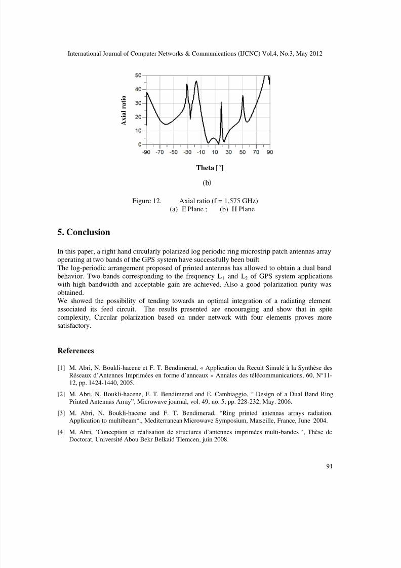
The Figure 12 shows that good right circular polarization is achieved for both planes, since the
magnitude of the axial ratio in the E plane is lower than 10 in all directions except [-90 °, -70], [-
60° , -50°], [-15°, -10°], [5°, 10°] and [30°, 90°].
For the H plane, one obtains a good polarization in the ranges [-5°, 20°] and [20°, 30°]. This
implies that the field in the right hand circular polarization dominates in these directions.
(b)
Theta [°]
Theta [°]
A x i a l r a t i o
(a)
A x i a l r a t i o
7/31/2019 Multi-Layered Ring Log-Periodic Antennas Array Design for GPS Systems
http://slidepdf.com/reader/full/multi-layered-ring-log-periodic-antennas-array-design-for-gps-systems 11/12
International Journal of Computer Networks & Communications (IJCNC) Vol.4, No.3, May 2012
91
Figure 12. Axial ratio (f = 1,575 GHz)(a) E Plane ; (b) H Plane
5. Conclusion
In this paper, a right hand circularly polarized log periodic ring microstrip patch antennas array
operating at two bands of the GPS system have successfully been built.
The log-periodic arrangement proposed of printed antennas has allowed to obtain a dual band
behavior. Two bands corresponding to the frequency L1 and L2 of GPS system applications
with high bandwidth and acceptable gain are achieved. Also a good polarization purity was
obtained.
We showed the possibility of tending towards an optimal integration of a radiating elementassociated its feed circuit. The results presented are encouraging and show that in spite
complexity, Circular polarization based on under network with four elements proves more
satisfactory.
References
[1] M. Abri, N. Boukli-hacene et F. T. Bendimerad, « Application du Recuit Simulé à la Synthèse des
Réseaux d’Antennes Imprimées en forme d’anneaux » Annales des télécommunications, 60, N°11-
12, pp. 1424-1440, 2005.
[2] M. Abri, N. Boukli-hacene, F. T. Bendimerad and E. Cambiaggio, “ Design of a Dual Band Ring
Printed Antennas Array”, Microwave journal, vol. 49, no. 5, pp. 228-232, May. 2006.
[3] M. Abri, N. Boukli-hacene and F. T. Bendimerad, “Ring printed antennas arrays radiation.
Application to multibeam“., Mediterranean Microwave Symposium, Marseille, France, June 2004.
[4] M. Abri, ‘Conception et réalisation de structures d’antennes imprimées multi-bandes ‘, Thèse de
Doctorat, Université Abou Bekr Belkaid Tlemcen, juin 2008.
Theta [°]
(b
A x i a l r a t i o

7/31/2019 Multi-Layered Ring Log-Periodic Antennas Array Design for GPS Systems
http://slidepdf.com/reader/full/multi-layered-ring-log-periodic-antennas-array-design-for-gps-systems 12/12
International Journal of Computer Networks & Communications (IJCNC) Vol.4, No.3, May 2012
92
[5] Abri. M., Boukli-hacene. N and Bendimerad. F. T., ‘Application du recuit simulé à la synthèse
d'antennes en réseau constituées d'éléments annulaires imprimés’ Annales des télécommunications,
60, N°11-12, pp. 1424-1440, 2005.
[6] Abri. M., Bendimerad. F. T., Boukli-hacene. N and Bousahla. M., ‘A Log Periodic Series-Fed
Antennas Array Design Using a Simple Transmission Line Model’. International Journal of
Electronics and Communication Engineering ISSN 0974-2166 Volume 2, Number 3, pp. 161–169,
2009.
[7] Abri. M., F. T. Bendimerad., N. Boukli-hacene., A. Benzenine et A. Laribi., “Un Simple modèle
pour la Synthèse des Réseaux d’Antennes Imprimmés log périodiques “., 4eme Séminaire sur les
systèmes de détection architecture et technologie DAT’2008. Alger, 23-25 Novembre 2008.
[8] Romodin. V. B, Oznobikhin. V. I and Kopylov. V. V, 'Log Periodic Microstrip Array', IEEE-Russia
conference, MIA-ME '99m 1999.
[9] R. Kakar and G. Kumar, ' Stagger Tuned Microstrip Log Periodic Antenna', IEEE conference, 1996.