multi function protective relay amr105 manual · backup facilities of differential protective...
TRANSCRIPT
Multi‐Function Protective Relay AMR105 Manual

Contents
Introduction…………………………………………………. ................................................................................. 1
Application Scope ........................................................................................................................ 1
Characteristics ............................................................................................................................. 2
Functions……………………………………………………. ................................................................................... 6
General ........................................................................................................................................ 6
Power System Data 1 ........................................................................................................... 6
2.1.1.1 Description .................................................................................................................... 6
2.1.1.2 Setting Notes ................................................................................................................. 6
2.1.1.3 Setting ......................................................................................................................... 10
2.1.1.4 Information List ........................................................................................................... 12
Oscillographic Fault Records .............................................................................................. 12
2.1.2.1 Description .................................................................................................................. 12
2.1.2.2 Setting Notes ............................................................................................................... 13
2.1.2.3 Setting ......................................................................................................................... 13
2.1.2.4 Information List ........................................................................................................... 14
Overcurrent Protection 50, 51, 50N, 51N ................................................................................. 14
General ............................................................................................................................... 14
Definite Time, High-set Elements 50-3, 50-2, 50N-3, 50N-2 ............................................. 15
Definite Time Overcurrent Elements 50-1, 50N-1 ............................................................. 17
Inverse Time Overcurrent Elements 51, 51N ..................................................................... 20
Inverse Time Overcurrent Protection 51V (Voltage-controlled / Voltage restraint) ......... 23
Dynamic Cold Load Pickup Function .................................................................................. 26
Inrush Restraint .................................................................................................................. 27
Pickup Logic and Tripping Logic ......................................................................................... 30
Two-phase Overcurrent Protection (Only Non-Directional) .............................................. 31
Setting Notes .................................................................................................................... 31
Settings ............................................................................................................................. 40
Information List ................................................................................................................ 42
Dynamic Cold Load Pickup ........................................................................................................ 44
Description ......................................................................................................................... 44
Setting Notes ...................................................................................................................... 46
Settings ............................................................................................................................... 48

Information List .................................................................................................................. 49
Single-Phase Overcurrent Protection ....................................................................................... 50
Functional Description ....................................................................................................... 50
High-impedance Ground Fault Unit Protection ................................................................. 51
Tank Leakage Protection .................................................................................................... 54
Setting Notes ...................................................................................................................... 54
Settings ............................................................................................................................... 60
Information List .................................................................................................................. 60
Voltage Protection 27, 59 ......................................................................................................... 60
Measurement Principle ...................................................................................................... 61
Overvoltage Protection 59 ................................................................................................. 62
Undervoltage Protection 27 ............................................................................................... 63
Setting Notes ...................................................................................................................... 66
Settings ............................................................................................................................... 70
Information List .................................................................................................................. 71
Negative Sequence Protection 46 ............................................................................................. 71
Definite Time Characteristic ............................................................................................... 72
Inverse Time Characteristic 46-TOC ................................................................................... 72
Setting Notes ...................................................................................................................... 75
Settings ............................................................................................................................... 78
Information List .................................................................................................................. 78
Frequency Protection 81 O/U ................................................................................................... 79
Description ......................................................................................................................... 79
Setting Notes ...................................................................................................................... 80
Settings ............................................................................................................................... 82
Information List .................................................................................................................. 82
Monitoring Functions ................................................................................................................ 83
Measurement Supervision ................................................................................................. 83
2.8.1.1 Monitoring of the Transformer Circuits ...................................................................... 83
2.8.1.2 Measurement Voltage Failure Detection ................................................................... 86
2.8.1.3 Broken Wire Monitoring of Voltage Transformer Circuits ......................................... 89
2.8.1.4 Setting Notes ............................................................................................................... 90
2.8.1.5 Settings ........................................................................................................................ 92
2.8.1.6 Information List ........................................................................................................... 93
Trip Circuit Supervision 74TC ............................................................................................. 93

2.8.2.1 Description .................................................................................................................. 94
2.8.2.2 Setting Notes ............................................................................................................... 96
2.8.2.3 Settings ........................................................................................................................ 97
2.8.2.4 Information List ........................................................................................................... 97
Breaker Failure Protection 50BF ............................................................................................... 98
Description ......................................................................................................................... 98
Setting Notes .................................................................................................................... 102
Settings ............................................................................................................................. 104
Information List ................................................................................................................ 105
Technical Data……………………………………………… ............................................................................. 105
Definite-time Overcurrent Protection .................................................................................... 105
Inverse-time Overcurrent Protection ..................................................................................... 106
Directional Overcurrent Protection ........................................................................................ 117
Inrush Restraint ....................................................................................................................... 118
Dynamic Cold Load Pickup ...................................................................................................... 119
Single-phase Overcurrent Protection ..................................................................................... 119
Voltage Protection .................................................................................................................. 120
Negative Sequence Protection (definite-time characteristic) ................................................ 122
Negative Sequence Protection (inverse-time characteristics)................................................ 123
VEBKO, AMR105, Manual
1 Introduction
Introduction
The device family AMPRO devices is introduced in this section. An overview of the devices is
presented in their application, characteristics, and scope of functions.
Application Scope
The numerical AMR105 multifunction protection relays are versatile devices designed for protection,
control and monitoring of busbar feeders. The devices can be used for line protection in networks
that are grounded, low-resistance grounded, isolated, or of a compensated neutral point structure.
They are suited for networks that are radial or looped, and for lines with single or multi-terminal feeds.
The devices are equipped with motor protection applicable for asynchronous machines of all sizes.
The devices include the functions that are necessary for protection, monitoring of circuit breaker
positions, and control of the circuit breakers in straight bus applications or breaker-and-a-half
configurations; therefore, the devices can be universally employed. The devices provide excellent
backup facilities of differential protective schemes of lines, transformers, generators, motors, and
busbars of all voltage levels.
Protective Functions
Non-directional overcurrent protection (50, 50N, 51, 51N) is the basis of the device. There are three
definite time overcurrent protective elements and one inverse time element for the phase currents
and the ground current. For inverse time overcurrent protective elements, several curves of different
standards are provided. Alternatively, user-defined characteristic can be programmed.
Depending on the version of the device that is ordered, the non-directional overcurrent protection
can be supplemented with directional overcurrent protection (67, 67N), breaker failure protection
(50BF), and sensitive ground fault detection for high-resistance ground faults. The highly sensitive
ground fault detection can be directional or non-directional.
In addition to the fault protection functions already mentioned, other protective functions are
available.Some of them depend on the version of the device that is ordered. These additional
functions include frequency protection (81O/U), overvoltage protection (59) and undervoltage
protection (27), negative sequence protection (46) and overload protection (49) with start inhibit for
motors (66/68), motor starting protection (48) and step change protection as well as automatic
reclosing (79) which allows different reclosing cycles on overhead lines. An automatic reclosing system
may also be connected externally. To ensure quick detection of the fault, the device is equipped with
a fault locator.
A protection feature can be ordered for the detection of intermittent ground faults which detects
and accumulates transient ground faults.
External detectors account for ambient temperatures or coolant temperatures (by means of an
external RTD-box).

VEBKO, AMR105, Manual
2 Introduction
Before reclosing after 3-pole tripping the AMR105 can verify the validity of the reclosure by means
of voltage check and/or synchrocheck. The synchronization function can also be controlled
externally.
Messages and Measured Values; Recording of Event and Fault Data
The operational indications provide information about conditions in the power system and the device.
Measurement quantities and values that are calculated can be displayed locally and communicated
via the serial interfaces.
Device messages can be assigned to a number of LEDs on the front cover (allocatable), can be
externally processed via output contacts (allocatable), linked with user-definable logic functions
and/or issued via serial interfaces.
During a fault (system fault) important events and changes in conditions are saved in fault protocols
(Event Log or Trip Log). Instantaneous fault values are also saved in the device and may be analyzed
subsequently.
Characteristics
Time Overcurrent Protection 50, 51, 50N, 51N
Three definite time overcurrent protective elements and one inverse time overcurrent
protective element for phase current and ground current IN or summation current 3I0
Two-phase operation of the overcurrent protection (IA, IC) is possible
Different curves of common standards are available for 51 and 51N, or a user-defined
characteristic
Blocking is possible, e.g. for reverse interlocking with any element
Instantaneous tripping by any element is possible when switching onto a fault
In-rush restraint with second harmonic current quantities.
Ground Fault Protection 50N, 51N
Three definite time overcurrent protective elements and one inverse time overcurrent
protective element applicable for grounded or high-resistance grounded systems
Different Curves of common standards are available for 51 and 51N, or a user-defined
characteristic
In-rush restraint with second harmonic current quantities.
Instantaneous tripping by any overcurrent element upon switch onto fault is possible.
Directional Time Overcurrent Protection 67, 67N

VEBKO, AMR105, Manual
3 Introduction
Four elements each for phase and ground operate in parallel to the non-directional
overcurrent protection elements. Their pickup values and time delays can be set
independently of these
Direction determination with cross-polarized voltages and voltage memory and
dynamically unlimited direction sensitivity
Fault direction is calculated phase-selectively and separately for phase faults, ground faults
and summation current faults.
Dynamic Cold Load Pick-up Function 50C, 50NC, 51C, 51NC, 67C,
67NC
Dynamic changeover of time overcurrent protection settings, e.g. when cold load
conditions are recognized
Detection of cold load condition via circuit breaker position or current threshold.
Activation via automatic reclosure (AR) is possible
Activation also possible via binary input.
Single-Phase Overcurrent Protection
Evaluation of the measured current via the sensitive or insensitive ground current
transformer
Suitable as differential protection that includes the neutral point current on transformer
side, generator side or motor side or for a grounded reactor set
As tank leakage protection against abnormal leakage currents between transformer tanks
and ground.
Voltage Protection 27, 59
Two element undervoltage detection via the positive-sequence system of the voltages,
phase-to-phase or phase-to-ground voltages
Choice of current supervision for 27-1 and 27-2
Two-element overvoltage detection via the positive sequence system voltages, negative
sequence system voltages, phase-to-phase or phase-to-ground voltages
For a single-phase connection, the connected single-phase phase-to-ground or phase-to-
phase voltage is evaluated
Settable dropout ratio for all elements of the undervoltage and overvoltage protection.
Negative Sequence Protection 46
Evaluation of the negative sequence component of the currents
VEBKO, AMR105, Manual
4 Introduction
Two definite-time elements 46-1 and 46-2 and one inverse-time element 46-TOC; curves
of common standards are available for 46-TOC.
Frequency Protection 81 O/U
Monitoring of falling below (f<) and/or exceeding (f>) with 4 frequency limits and time
delays that are independently adjustable
Insensitive to harmonics and abrupt phase angle changes
Adjustable undervoltage threshold.
Thermal Overload Protection 49
Thermal profile of energy losses (overload protection has full memory capability)
True r.m.s. calculation
Adjustable thermal warning element
Adjustable alarm level based on current magnitude
Additional time constant setting for motors to accommodate the motor at standstill
Integration of ambient temperature or coolant temperature is possible via external
temperature sensors and RTD-Box.
Monitoring Functions
Reliability of the device is greatly increased because of self-monitoring of the internal
measurement circuits,
the auxiliary power supply as well as the hardware and software
Monitoring of the current transformer and voltage transformer secondary circuits using
summation and symmetry
check techniques
Trip circuit monitoring possible
Phase rotation check.
Ground Fault Detection 50N(s), 51N(s), 67N(s), 59N/64
Displacement voltage is measured or calculated from the three phase voltages.
Determination of a faulty phase on ungrounded or grounded systems.
Two-element Ground Fault Detection: 50Ns-1 and 50Ns-2;
High sensitivity (as low as 1 mA)
Overcurrent element with definite time or inverse time delay.
VEBKO, AMR105, Manual
5 Introduction
For inverse time overcurrent protection, characteristics according to IEC or ANSI standards,
one userdefined and two logarithmic inverse current/time characteristics are available.
Direction determination with zero sequence quantities(I0, V0), wattmetric ground fault
direction determination.
Any element can be set as directional or non-directional — forward sensing directional, or
reverse sensing directional
Directional characteristic curve adjustable
Optionally applicable as additional ground fault protection.
Breaker Failure Protection 50 BF
By checking the current and/or evaluating the circuit breaker auxiliary contacts
Started by any integrated protection function that trips
Initiation possible via a binary input from an external protective device.
Phase Rotation
Selectable ABC or ACB by setting (static) or binary input (dynamic).

VEBKO, AMR105, Manual
6 Functions
Functions
This chapter describes the numerous functions available on the AMPRO device AMR105. It shows the
setting possibilities for each function in maximum configuration. Information with regard to the
determination of setting values as well as formulas, if required, are also provided.
General
Power System Data 1
Description
The device requires certain basic data regarding the protected equipment so that the device can
adapt to its desired application. These may be, for instance, nominal power system and transformer
data, measured quantity polarities and their physical connections, breaker properties (where
applicable) etc. There are also certain parameters that are common to all functions, i.e. not associated
with a specific protection, control or monitoring function. The following section discusses these
parameters.
Setting Notes
Rated Frequency (Power System)
The nominal frequency of the system is set under the Address 214 Rated Frequency. The factory pre-
setting in accordance with the model need only be changed if the device will be employed for a
purpose other than that which was planned when ordering.
Phase Rotation (Power System)
Address 209 PHASE SEQ. is used to change the default phase sequence (A B C for clockwise rotation)
if your power system permanently has an anti-clockwise phase sequence (A C B). A temporary
reversal of rotation is also possible using binary inputs.
Temperature Unit (Power System )
Address 276 TEMP.UNIT allows displaying the temperature values either in degrees Celsius or in
degrees Fahrenheit.
Polarity of Current Transformers (Power System )
At address 201 CT Starpoint, the polarity of the wye-connected current transformers is specified
(the following figure applies accordingly to two current transformers). This setting determines the
measuring direction of the device (forward = line direction). Changing this parameter also results in a
polarity reversal of the ground current inputs IN or INS.

VEBKO, AMR105, Manual
7 Functions
Figure 2-1 Polarity of current transformers
Current Connection I4 (Power System)
Here, it is communicated to the device whether the ground current of the current transformer
neutral point is connected to the fourth current input (I4). This corresponds to the Holmgreen
connection. In this case, parameter 280 Holmgr. for i is set to YES. In all other cases,even if the
ground current of the own line is measured via a separate ground current transformer, enter the
setting NO. This setting exclusively affects the function „Current Sum Monitoring“ .
Current Connection (Power System)
Via parameter 251 CT Connect. a special connection of the current transformers can be determined.
The standard connection is A, B, C, (Gnd). It may only be changed if the device is set to measure
one or more ground currents via two current inputs. The standard connection applies to all other
cases.
Voltage Connection (Power System)
Address 213 determines how the voltage transformers are connected.
VT Connect. 3ph = Van, Vbn, Vcn means that three phase voltages are wye-connected.
VT Connect. 3ph = Vab, Vbc, VGnd means that two phase-to-phase voltages (open delta voltage)
and Vgnd are connected. The latter setting also has to be selected when only two phase-to-phase
voltage transformers are used or when only the displacement voltage (zero sequence voltage) is
connected to the device. Vab, Vbc, Vx if two phase-to-phase voltages (open-delta connection) and
any third voltage Vx are connected. Vx is used exclusively for the flexible protection functions. The
transformer nominal voltages for Vx are set at address 207 and 208.
VT Connect. 3ph = Van,Vbn,Vcn,VGn is selected if the three phase voltages in wye-connection and
VN are connected to the fourth voltage input of the device.
VEBKO, AMR105, Manual
8 Functions
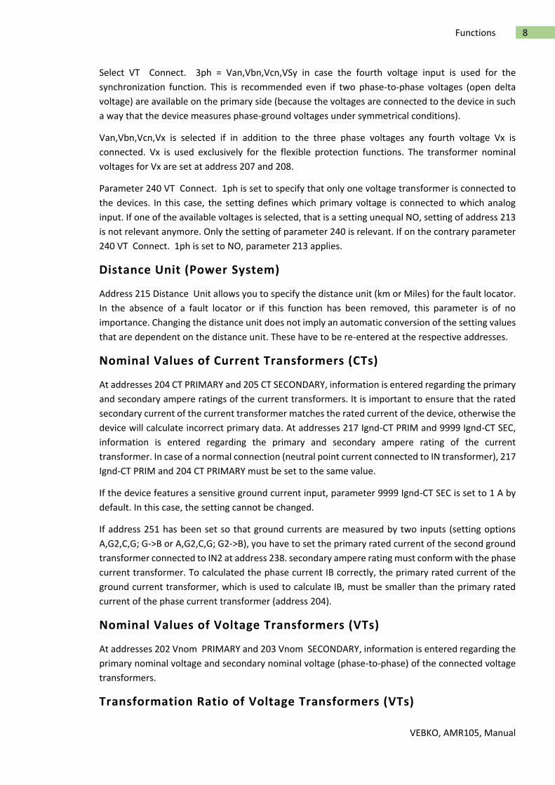
Select VT Connect. 3ph = Van,Vbn,Vcn,VSy in case the fourth voltage input is used for the
synchronization function. This is recommended even if two phase-to-phase voltages (open delta
voltage) are available on the primary side (because the voltages are connected to the device in such
a way that the device measures phase-ground voltages under symmetrical conditions).
Van,Vbn,Vcn,Vx is selected if in addition to the three phase voltages any fourth voltage Vx is
connected. Vx is used exclusively for the flexible protection functions. The transformer nominal
voltages for Vx are set at address 207 and 208.
Parameter 240 VT Connect. 1ph is set to specify that only one voltage transformer is connected to
the devices. In this case, the setting defines which primary voltage is connected to which analog
input. If one of the available voltages is selected, that is a setting unequal NO, setting of address 213
is not relevant anymore. Only the setting of parameter 240 is relevant. If on the contrary parameter
240 VT Connect. 1ph is set to NO, parameter 213 applies.
Distance Unit (Power System)
Address 215 Distance Unit allows you to specify the distance unit (km or Miles) for the fault locator.
In the absence of a fault locator or if this function has been removed, this parameter is of no
importance. Changing the distance unit does not imply an automatic conversion of the setting values
that are dependent on the distance unit. These have to be re-entered at the respective addresses.
Nominal Values of Current Transformers (CTs)
At addresses 204 CT PRIMARY and 205 CT SECONDARY, information is entered regarding the primary
and secondary ampere ratings of the current transformers. It is important to ensure that the rated
secondary current of the current transformer matches the rated current of the device, otherwise the
device will calculate incorrect primary data. At addresses 217 Ignd-CT PRIM and 9999 Ignd-CT SEC,
information is entered regarding the primary and secondary ampere rating of the current
transformer. In case of a normal connection (neutral point current connected to IN transformer), 217
Ignd-CT PRIM and 204 CT PRIMARY must be set to the same value.
If the device features a sensitive ground current input, parameter 9999 Ignd-CT SEC is set to 1 A by
default. In this case, the setting cannot be changed.
If address 251 has been set so that ground currents are measured by two inputs (setting options
A,G2,C,G; G->B or A,G2,C,G; G2->B), you have to set the primary rated current of the second ground
transformer connected to IN2 at address 238. secondary ampere rating must conform with the phase
current transformer. To calculated the phase current IB correctly, the primary rated current of the
ground current transformer, which is used to calculate IB, must be smaller than the primary rated
current of the phase current transformer (address 204).
Nominal Values of Voltage Transformers (VTs)
At addresses 202 Vnom PRIMARY and 203 Vnom SECONDARY, information is entered regarding the
primary nominal voltage and secondary nominal voltage (phase-to-phase) of the connected voltage
transformers.
Transformation Ratio of Voltage Transformers (VTs)

VEBKO, AMR105, Manual
9 Functions
Address 206 Vph / Vdelta informs the device of the adjustment factor between the phase voltage
and the displacement voltage. This information is relevant for the processing of ground faults (in
grounded systems and ungrounded systems), for the operational measured value VN and measured-
variable monitoring.
If the voltage transformer set provides open delta windings and if these windings are connected to
the device, this must be specified accordingly in address 213. Since the voltage transformer ratio is
normally as follows:
the factor Vph/VN (secondary voltage, address 206 Vph / Vdelta) must be set to 3/ √3=√3 = 1.73
which must be used if the VN voltage is connected. For other transformation ratios, i.e. the formation
of the displacement voltage via an interconnected transformer set, the factor must be corrected
accordingly.
Please take into consideration that also the calculated secondary V0-voltage is divided by the value
set in address 206. Thus, even if the V0-voltage is not connected, address 206 has an impact on the
secondary operational measured value VN.
Trip and Close Command Duration (Breaker)
In address 210 the minimum trip command duration TMin TRIP CMD is set. This setting applies to
all protection functions that can initiate tripping.
In address 211 the maximum close command duration TMax CLOSE CMD is set. It applies to the
integrated reclosing function. It must be set long enough to ensure that the circuit breaker has
securely closed. An excessive duration causes no problem since the closing command is interrupted
in the event another trip is initiated by a protection function.
Current Flow Monitoring (Breaker)
In address 212 BkrClosed I MIN the pickup threshold of the integrated current flow monitoring
function can be set. This parameter is used by several protection functions (e.g. voltage protection
with current criterion, overload protection, load jam protection, restart inhibit for motors and circuit
breaker maintenance). If the set current value is exceeded, the circuit breaker is considered closed.
The threshold value setting applies to all three phases, and must take into consideration all used
protection functions.
The pickup threshold for the breaker failure protection is set separately.
When using the device as motor protection and using the overload protection, load jam protection
and restart inhibit, the protective relay can distinguish between a running motor and a stopped
VEBKO, AMR105, Manual
10 Functions
motor, as well as take into account the different motor cooldown behavior. For this application, the
set value must be lower than the minimum no-load current of the motor.
Circuit-breaker Maintenance (Breaker)
Parameters 260 to 267 are assigned to CB maintenance. The parameters and the different
procedures are explained in the setting notes of this function.
Two-phase Time Overcurrent Protection (Protection Operating
Quantities)
The two-phase overcurrent protection functionality is used in grounded or compensated systems
where interaction of three-phase devices with existing two-phase protection equipment is required.
Via parameter 250 50/51 2-ph prot the time overcurrent protection can be configured to two or
three-phase operation. If the parameter is set to ON, the value 0 A instead of the measured value for
IB is used permanently for the threshold comparison so that no pickup is possible in phase B. All other
functions, however, operate in three phases.
Ground Fault Protection (Protection Operating Quantities)
Parameter 613 50N/51N/67N w. defines whether ground fault protection, breaker failure protection
or Fuse Failure Monitor is either to operate using measured values (Ignd (measured)) or the quantities
calculated from the three phase currents (3I0 (calcul.)). In the first case, the measured quantity at the
fourth current input is evaluated. In the latter case, the summation current is calculated from the three
phase current inputs. If the device features a sensitive ground current input (measuring range starts at
1 mA), the ground fault protection always uses the calculated variable 3I0. In this case, parameter 613
50N/51N/67N w. is not available.
Voltage Protection (Protection Operating Quantities)
In a three-phase connection, the fundamental harmonic of the largest of the three phase-to-phase
voltages (Vphph) or phase-to-ground voltages (Vph-n) or the positive sequence voltage (V1) or the
negative sequence voltage (V2) is supplied to the overvoltage protection elements. In three-phase
connection, undervoltage protection relies either on the positive sequence voltage (V1) or the
smallest of the phase-to-phase voltages (Vphph) or the phase-to-ground voltages (Vph-n). This is
configured by setting the parameter value in address 614 OP. QUANTITY 59 and 615 OP. QUANTITY
27. With single-phase voltage transformer connection, a direct comparison of the measured
quantities with the threshold values is carried out and the parameterization of the characteristic
quantity switchover is ignored.
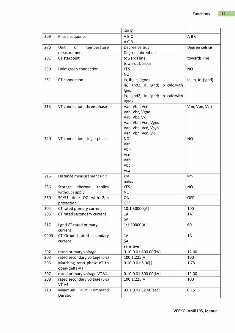
Setting
The table indicates region-specific default settings. Column C (configuration) indicates the
corresponding secondary nominal current of the current transformer.
Adr. Parameter C Setting options Default Setting
214 Rated Frequency 50HZ 50HZ
VEBKO, AMR105, Manual
11 Functions
60HZ
209 Phase sequence A B C A C B
A B C
276 Unit of temperature measurement
Degree celsius Degree fahrenheit
Degree celsius
201 CT starpoint towards line towards busbar
towards line
280 Holmgreen connection YES NO
NO
251 CT connection Ia, Ib, Ic, (Ignd) Ia, Ignd2, Ic, Ignd; Ib calc.with Ignd Ia, Ignd2, Ic, Ignd; Ib calc.with Ignd2
Ia, Ib, Ic, (Ignd)
213 VT connection, three-phase Van, Vbn, Vcn Vab, Vbc, Vgnd Vab, Vbc, Vx Van, Vbn, Vcn, Vgnd Van, Vbn, Vcn, Vsyn Van, Vbn, Vcn, Vx
Van, Vbn, Vcn
240 VT connection, single-phase NO Van Vbn Vcn Vab Vbc Vca
NO
215 Distance measurement unit km miles
km
236 Storage thermal replica without supply
YES NO
NO
250 50/51 time OC with 2ph protection
ON OFF
OFF
204 CT rated primary current 10:1:50000[A] 100
205 CT rated secondary current 1A 5A
1A
217 I gnd CT rated primary current
1:1:50000[A] 60
9999 CT Ground rated secondary current
1A 5A sensitive
1A
202 rated primary voltage 0.10:0.01:800.00[kV] 12.00
203 rated secondary voltage (L-L) 100:1:225[V] 100
206 Matching ratio phase-VT to open-delta-VT
0.10:0.01:3.00[] 1.73
207 rated primary voltage VT V4 0.10:0.01:800.00[kV] 12.00
208 rated secondary voltage (L-L) VT V4
100:1:225[V] 100
210 Minimum TRIP Command Duration
0.01:0.01:32.00[sec] 0.15
VEBKO, AMR105, Manual
12 Functions
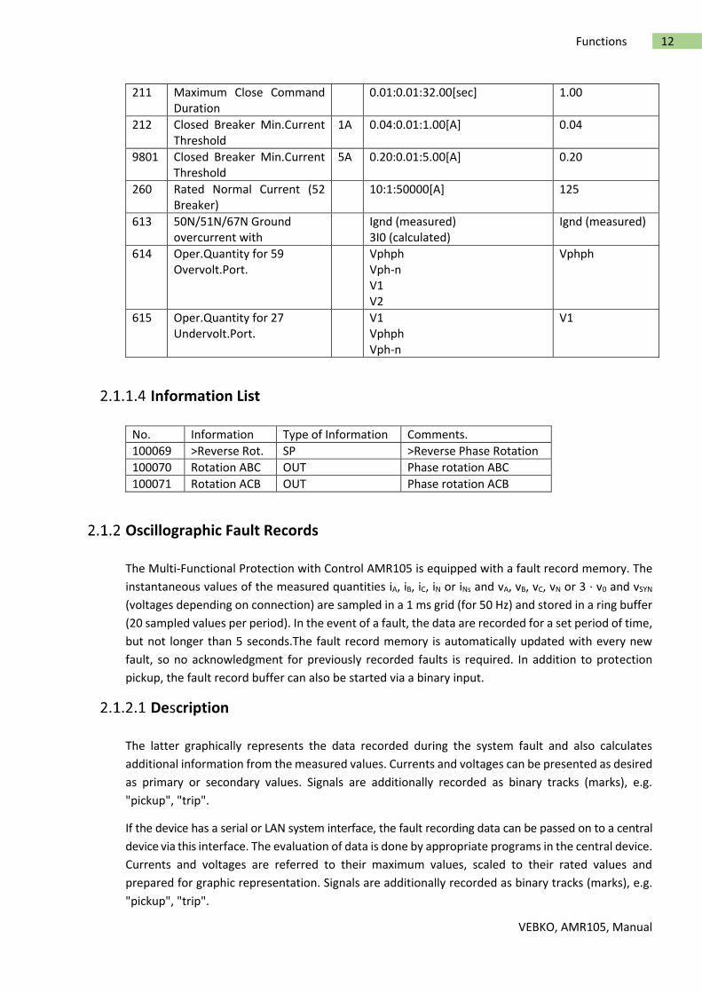
211 Maximum Close Command Duration
0.01:0.01:32.00[sec] 1.00
212 Closed Breaker Min.Current Threshold
1A 0.04:0.01:1.00[A] 0.04
9801 Closed Breaker Min.Current Threshold
5A 0.20:0.01:5.00[A] 0.20
260 Rated Normal Current (52 Breaker)
10:1:50000[A] 125
613 50N/51N/67N Ground overcurrent with
Ignd (measured) 3I0 (calculated)
Ignd (measured)
614 Oper.Quantity for 59 Overvolt.Port.
Vphph Vph-n V1 V2
Vphph
615 Oper.Quantity for 27 Undervolt.Port.
V1 Vphph Vph-n
V1
Information List
No. Information Type of Information Comments.
100069 >Reverse Rot. SP >Reverse Phase Rotation
100070 Rotation ABC OUT Phase rotation ABC
100071 Rotation ACB OUT Phase rotation ACB
Oscillographic Fault Records
The Multi-Functional Protection with Control AMR105 is equipped with a fault record memory. The
instantaneous values of the measured quantities iA, iB, iC, iN or iNs and vA, vB, vC, vN or 3 · v0 and vSYN
(voltages depending on connection) are sampled in a 1 ms grid (for 50 Hz) and stored in a ring buffer
(20 sampled values per period). In the event of a fault, the data are recorded for a set period of time,
but not longer than 5 seconds.The fault record memory is automatically updated with every new
fault, so no acknowledgment for previously recorded faults is required. In addition to protection
pickup, the fault record buffer can also be started via a binary input.
Description
The latter graphically represents the data recorded during the system fault and also calculates
additional information from the measured values. Currents and voltages can be presented as desired
as primary or secondary values. Signals are additionally recorded as binary tracks (marks), e.g.
"pickup", "trip".
If the device has a serial or LAN system interface, the fault recording data can be passed on to a central
device via this interface. The evaluation of data is done by appropriate programs in the central device.
Currents and voltages are referred to their maximum values, scaled to their rated values and
prepared for graphic representation. Signals are additionally recorded as binary tracks (marks), e.g.
"pickup", "trip".
VEBKO, AMR105, Manual
13 Functions
Transfer to a central device can be polled automatically, either after each fault detection by the
protection, or only after a trip.
Setting Notes
Configuration
Fault recording (waveform capture) will only take place if address 104 OSC. FAULT REC. is set to
Enabled. Other settings pertaining to fault recording (waveform capture) are found in the OSC. FAULT
REC. submenu of the SETTINGS menu. Waveform capture makes a distinction between the trigger
instant for an oscillographic record and the criterion to save the record (address 401
WAVEFORMTRIGGER). Normally, the trigger is the pickup of a protection element, i.e. the time 0 is
defined as the instant the first protection function picks up. The criterion for saving may be both the
device pickup (Save w. Pickup) or the device trip (Save w. TRIP). A trip command issued by the
device can also be used as trigger instant (Start w. TRIP), in this case it is also
the saving criterion. A fault event starts with the pickup by any protection function and ends when
the last pickup of a protection function has dropped out. Usually this is also the extent of a fault
recording (address 402 WAVEFORM DATA = Fault event). If automatic reclosing is performed, the
entire system fault — with several reclosing attempts if necessary — can be recorded until the fault
has been cleared for good (address 402 WAVEFORM DATA = Pow.Sys.Flt.). This facilitates the
representation of the entire system fault history, but also consumes storage capacity during the
automatic reclosing dead time(s).
The actual storage time begins at the pre-fault time PRE. TRIG. TIME (address 404) ahead of the
reference instant, and ends at the post-fault time POST REC. TIME (address 405) after the storage
criterion has reset. The maximum storage duration of each fault record (MAX. LENGTH) is entered
at address 403. Recording per fault must not exceed 5 seconds. An oscillographic record can be
triggered by a status change of a binary input. Storage is then triggered dynamically. The length of
the fault recording is set in address 406 Bin In CAPT.TIME (but not longer than MAX. LENGTH, address
403). Pre-fault and post-fault times will add to this. If the binary input time is set to ∞, the length of
the record equals the time that the binary input is activated (static), but not longer than the MAX.
LENGTH (address 403).
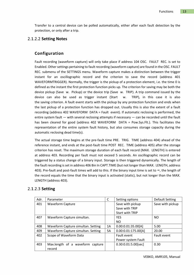
Setting
Adr. Parameter C Setting options Default Setting
401 Waveform Capture Save with pickup Save with TRIP Start with TRIP
Save with pickup
407 Waveform Capture simultan. YES NO
NO
408 Waveform Capture simultan. Setting 1A 0.00:0.01:35.00[A] 5.00
409 Waveform Capture simultan. Setting 5A 0.00:0.01:175.00[A] 20.00
402 Scope of Waveform Data Fault event Power system Fault
Fault event
403 Max.length of a waveform capture record
0.30:0.01:5.00[sec] 0.30
VEBKO, AMR105, Manual
14 Functions
404 Captured waveform prior to trigger 0.05:0.01:0.50[sec] 0.05
405 Captured Waveform after event 0.05:0.01:0.50[sec] 0.05
406 Capture Time via binary input 0.10:0.01:5.00,oo[sec] 0.50
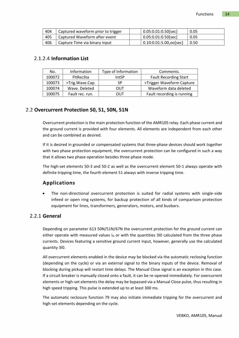
Information List
No. Information Type of Information Comments.
100072 FltRecSta IntSP Fault Recording Start
100073 >Trig.Wave.Cap. SP >Trigger Waveform Capture
100074 Wave. Deleted OUT Waveform data deleted
100075 Fault rec. run. OUT Fault recording is running
Overcurrent Protection 50, 51, 50N, 51N
Overcurrent protection is the main protection function of the AMR105 relay. Each phase current and
the ground current is provided with four elements. All elements are independent from each other
and can be combined as desired.
If it is desired in grounded or compensated systems that three-phase devices should work together
with two phase protection equipment, the overcurrent protection can be configured in such a way
that it allows two phase operation besides three-phase mode.
The high-set elements 50-3 and 50-2 as well as the overcurrent element 50-1 always operate with
definite tripping time, the fourth element 51 always with inverse tripping time.
Applications
The non-directional overcurrent protection is suited for radial systems with single-side
infeed or open ring systems, for backup protection of all kinds of comparison protection
equipment for lines, transformers, generators, motors, and busbars.
General
Depending on parameter 613 50N/51N/67N the overcurrent protection for the ground current can
either operate with measured values IN or with the quantities 3I0 calculated from the three phase
currents. Devices featuring a sensitive ground current input, however, generally use the calculated
quantity 3I0.
All overcurrent elements enabled in the device may be blocked via the automatic reclosing function
(depending on the cycle) or via an external signal to the binary inputs of the device. Removal of
blocking during pickup will restart time delays. The Manual Close signal is an exception in this case.
If a circuit breaker is manually closed onto a fault, it can be re-opened immediately. For overcurrent
elements or high-set elements the delay may be bypassed via a Manual Close pulse, thus resulting in
high speed tripping. This pulse is extended up to at least 300 ms.
The automatic reclosure function 79 may also initiate immediate tripping for the overcurrent and
high-set elements depending on the cycle.

VEBKO, AMR105, Manual
15 Functions
Pickup of the definite-time elements can be stabilized by setting the dropout times. This protection
is used in systems where intermittent faults occur. Combined with electromechanical relays, it allows
different dropout responses to be adjusted and a time grading of digital and electromechanical relays
to be implemented.
Pickup and delay settings may be quickly adapted to system requirements via dynamic setting
changeover.
Tripping by the 50-1 and 51 elements (in phases), 50N-1 and 51N elements (in ground path) may be
blocked for inrush conditions by utilizing the inrush restraint feature.
The following table gives an overview of the interconnections to other functions of the devices
AMR105.
Table 2-1 Interconnection to other functions
Definite Time, High-set Elements 50-3, 50-2, 50N-3, 50N-2
For each element, an individual pickup value 50-3 PICKUP, 50-2 PICKUP or 50N-3 PICKUP, 50N-2
PICKUP is set. For 50-3 PICKUP and 50N-3 PICKUP, it is possible to measure the Instantaneous in
addition to Fundamental and True RMS. If set to Instantaneous, the element picks up at 2 2 · setting
value(rms). Each phase and ground current is compared separately per element with the common
pickup values 50-3 PICKUP, 50-2 PICKUP or 50N-3 PICKUP, 50N-2 PICKUP. If the respective pickup
value is exceeded,this is signaled. After the user-defined time delays 50-3 DELAY, 50-2 DELAY or 50N-
3 DELAY, 50N-2 DELAY have elapsed, trip commands are issued which are available for each element.
The dropout value is roughly equal to 95% of the pickup value for currents > 0.3 INom. If the
measurement of the instantaneous values has been parameterized for the 50-3 PICKUP or 50N-3
element, the dropout ratio is set to 90 %.
Pickup can be stabilized by setting dropout times 1215 50 T DROP-OUT or 1315 50N T DROP-OUT.
This time is started and maintains the pickup condition if the current falls below the threshold.
Therefore, the function does not drop out at high speed. The trip delay time 50-3 DELAY, 50-2 DELAY
or 50N-3 DELAY, 50N-2 DELAY continues running in the meantime. After the dropout delay time has
elapsed, the pickup is reported OFF and the trip delay time is reset unless the threshold 50-3 PICKUP,
50-2 PICKUP or 50N-3 PICKUP, 50N-2 PICKUP has been exceeded again. If the threshold is exceeded
again during the dropout delay time,
VEBKO, AMR105, Manual
16 Functions
the time is canceled. The trip delay time 50-3 DELAY, 50-2 DELAY or 50N-3 DELAY, 50N-2 DELAY
continues running in the meantime. If the threshold value is exceeded after this time has elapsed,
the trip command is issued immediately. If the threshold value is not exceeded at this time, there is
no reaction. If the threshold value is exceeded again after expiry of the trip command delay time
while the dropout delay time is still running, tripping is initiated immediately.
These elements can be blocked by the automatic reclosing function (79 AR).
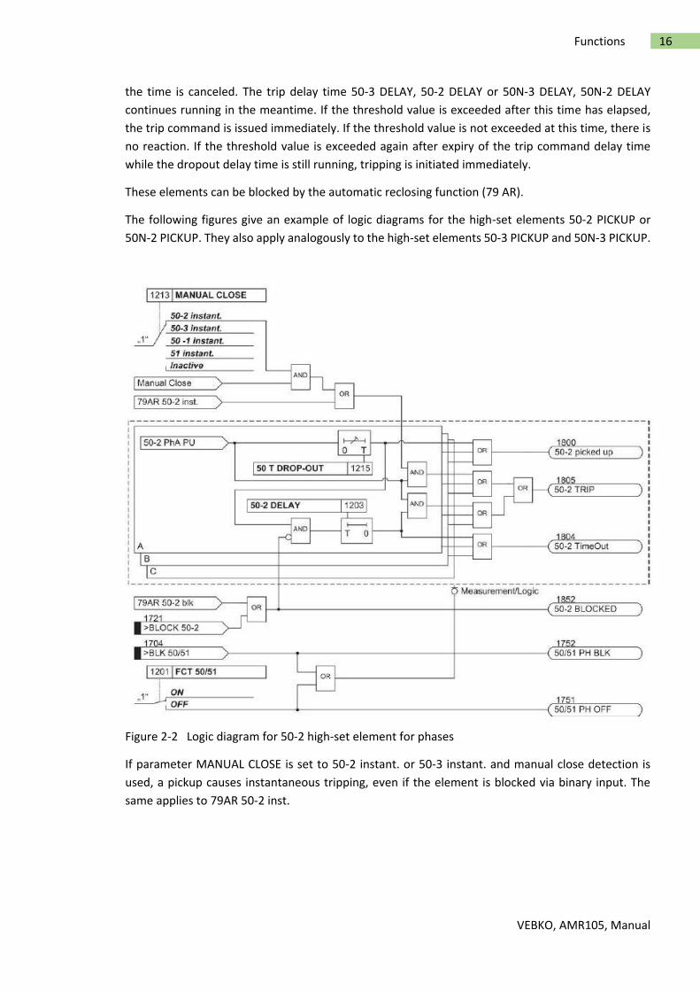
The following figures give an example of logic diagrams for the high-set elements 50-2 PICKUP or
50N-2 PICKUP. They also apply analogously to the high-set elements 50-3 PICKUP and 50N-3 PICKUP.
Figure 2-2 Logic diagram for 50-2 high-set element for phases
If parameter MANUAL CLOSE is set to 50-2 instant. or 50-3 instant. and manual close detection is
used, a pickup causes instantaneous tripping, even if the element is blocked via binary input. The
same applies to 79AR 50-2 inst.
VEBKO, AMR105, Manual
17 Functions
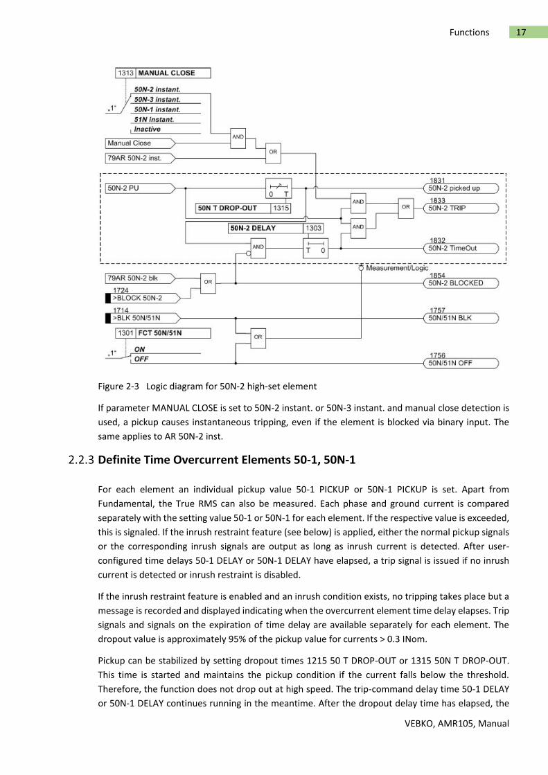
Figure 2-3 Logic diagram for 50N-2 high-set element
If parameter MANUAL CLOSE is set to 50N-2 instant. or 50N-3 instant. and manual close detection is
used, a pickup causes instantaneous tripping, even if the element is blocked via binary input. The
same applies to AR 50N-2 inst.
Definite Time Overcurrent Elements 50-1, 50N-1
For each element an individual pickup value 50-1 PICKUP or 50N-1 PICKUP is set. Apart from
Fundamental, the True RMS can also be measured. Each phase and ground current is compared
separately with the setting value 50-1 or 50N-1 for each element. If the respective value is exceeded,
this is signaled. If the inrush restraint feature (see below) is applied, either the normal pickup signals
or the corresponding inrush signals are output as long as inrush current is detected. After user-
configured time delays 50-1 DELAY or 50N-1 DELAY have elapsed, a trip signal is issued if no inrush
current is detected or inrush restraint is disabled.
If the inrush restraint feature is enabled and an inrush condition exists, no tripping takes place but a
message is recorded and displayed indicating when the overcurrent element time delay elapses. Trip
signals and signals on the expiration of time delay are available separately for each element. The
dropout value is approximately 95% of the pickup value for currents > 0.3 INom.
Pickup can be stabilized by setting dropout times 1215 50 T DROP-OUT or 1315 50N T DROP-OUT.
This time is started and maintains the pickup condition if the current falls below the threshold.
Therefore, the function does not drop out at high speed. The trip-command delay time 50-1 DELAY
or 50N-1 DELAY continues running in the meantime. After the dropout delay time has elapsed, the

VEBKO, AMR105, Manual
18 Functions
pickup is reported OFF and the trip delay time is reset unless the threshold 50-1 or 50N-1 has been
exceeded again. If the threshold is exceeded again during the dropout delay time, the time is
canceled. However, the trip-command delay time 50-1 DELAY or 50N-1 DELAY continues running. If
the threshold value is exceeded after its expiry, the trip command is issued immediately. If the
threshold value is not exceeded at this time, there is no reaction. If the threshold value is exceeded
again after expiry of the trip-command delay time, while the dropout delay time is still running,
tripping occurs immediately.
Pickup stabilization of the overcurrent elements 50-1 or 50N-1 by means of settable dropout time is
deactivated if an inrush pickup is present since an inrush does not represent an intermittent fault.
These elements can be blocked by the automatic reclosing function (79 AR).
The following figures show the logic diagrams for the current elements 50-1 and 50N-1.
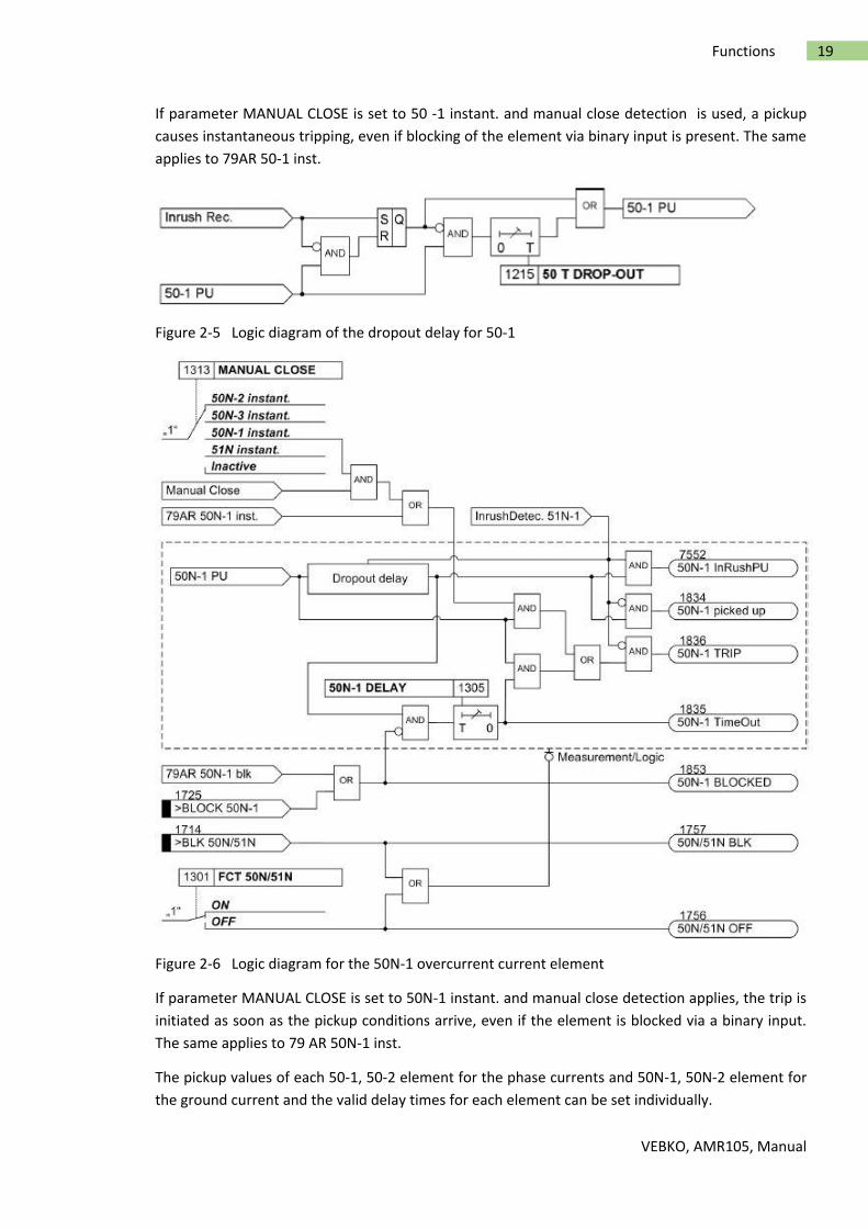
Figure 2-4 Logic diagram for the 50-1 overcurrent element for phases
The dropout delay only operates if no inrush was detected. An incoming inrush will reset a running
dropout delay time.
VEBKO, AMR105, Manual
19 Functions
If parameter MANUAL CLOSE is set to 50 -1 instant. and manual close detection is used, a pickup
causes instantaneous tripping, even if blocking of the element via binary input is present. The same
applies to 79AR 50-1 inst.
Figure 2-5 Logic diagram of the dropout delay for 50-1
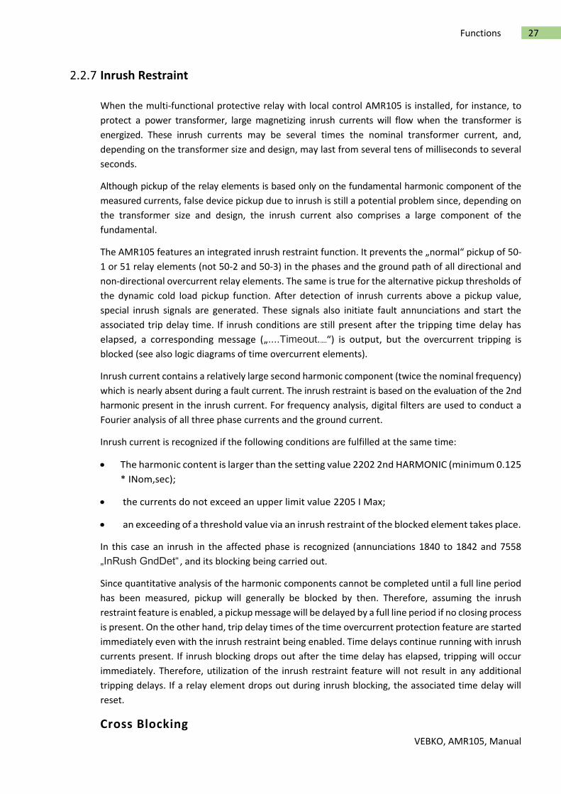
Figure 2-6 Logic diagram for the 50N-1 overcurrent current element
If parameter MANUAL CLOSE is set to 50N-1 instant. and manual close detection applies, the trip is
initiated as soon as the pickup conditions arrive, even if the element is blocked via a binary input.
The same applies to 79 AR 50N-1 inst.
The pickup values of each 50-1, 50-2 element for the phase currents and 50N-1, 50N-2 element for
the ground current and the valid delay times for each element can be set individually.

VEBKO, AMR105, Manual
20 Functions
The dropout delay only functions if no inrush was detected. An incoming inrush will reset a running
dropout time delay.
Figure 2-7 Logic of the dropout delay for 50N-1
Inverse Time Overcurrent Elements 51, 51N
The inverse-time elements depend on the ordered variant. They operate with an inverse-time
characteristic either in accordance with the IEC or the ANSI standard or with a user-defined
characteristic. The characteristics and the equations they are based on are given in the Technical Data.
When configuring one of the inverse-time characteristics, the definite-time elements 50-3, 50-2,and
50-1 are also active (see Section "Definite-time High-set Current Elements 50-3, 50-2, 50N-3, 50N-2 "
and "Definite-time Overcurrent Elements 50-1, 50N-1 ").
A voltage restraint can optionally be set (see Section „Inverse Time Overcurrent Protection (Voltage-
controlled / Voltage-restraint“).
Pickup Behavior
For each element, an individual pickup value 51 PICKUP or 51N PICKUP is set. Apart from
Fundamental, the True RMS can also be measured. Each phase and ground current is separately
compared with the setting value 51 or 51N per element. If a current exceeds 1.1 times the setting
value, the corresponding element picks up and is signaled individually. If the inrush restraint function
is used, either the normal pickup signals or the corresponding inrush signals are issued as long as
inrush current is detected. If the 51 element picks up, the tripping time is calculated from the actual
fault current flowing, using an integrating method of measurement.The calculated tripping time
depends on the selected tripping curve. Once this time has elapsed, a trip signal is issued provided
that no inrush current is detected or inrush restraint is disabled. If the inrush restraint function is
enabled and an inrush condition exists, no tripping takes place but a message is issued indicating
when the overcurrent element time delay elapses.
These elements can be blocked by the automatic reclosing feature (79 AR).
For ground current element 51N, the characteristic may be selected independently of the
characteristic used for phase currents.
Pickup values of elements 51 (phase currents) and 51N (ground current) and the relevant time
multiplicators may be set individually.
The following two figures show the logic diagrams for the inverse time overcurrent protection.

VEBKO, AMR105, Manual
21 Functions
Figure 2-8 Logic diagram of the inverse-time overcurrent protection element for phases
If parameter MANUAL CLOSE is set to 51 instant. and manual close detection applies, the trip is
initiated as soon as the pickup conditions arrive, even if the element is blocked via a binary input.
The same applies to 79AR 51 inst.

VEBKO, AMR105, Manual
22 Functions
Figure 2-9 Logic diagram of the inverse-time overcurrent protection element for ground
If parameter MANUAL CLOSE is set to 51N instant. and manual close detection applies, the trip is
initiated as soon as the pickup conditions arrive, even if the element is blocked via binary input. The
same applies to 79AR 51N instantaneous.
Dropout Behavior
For the ANSI or IEC characteristics, you can select whether an element drops out instantaneously
after a threshold has been undershot or whether dropout is performed by means of disk emulation.
"Instantaneous" means that the picked-up element drops out when 95 % of the pickup value is
undershot. For a new pickup, the time delay starts at zero.
The disk emulation evokes a dropout process (timer counter is decrementing) which begins after de-
energization. This process corresponds to the reset of a Ferraris disk (explaining its denomination
"disk emulation"). In case several faults occur in succession, the "history" is taken into consideration
due to the inertia of the Ferraris disk and the time response is adapted. Reset begins as soon as 90 %
of the setting value is undershot, in accordance to the dropout curve of the selected characteristic.
In the range between the dropout value (95 % of the pickup value) and 90 % of the setting value, the
incrementing and the decrementing processes are in idle state.

VEBKO, AMR105, Manual
23 Functions
Disk emulation offers advantages when the overcurrent relay elements must be coordinated with
conventional electromechanical overcurrent relays located towards the source.
User-defined Characteristics
When user-defined characteristic are used, the tripping curve may be defined point by point. Up to
20 value pairs (current, time) may be entered. The device then approximates the characteristic, using
linear interpolation.
The dropout curve may be user-defined as well. See dropout behavior for ANSI and IEC curves in the
function description. If no user-defined dropout curve is required, the element drops out as soon as
the respective current falls below approx. 95% of the set pickup value. When a new pickup is evoked,
the timer starts at zero again.
Inverse Time Overcurrent Protection 51V (Voltage-controlled / Voltage
restraint)
Undervoltage Consideration
The inverse time overcurrent protection is provided with an undervoltage detection that can be
disabled (address 1223 VOLT. INFLUENCE ). This function can influence overcurrent detection by
means of two different methods:
Voltage-controlled: If a set voltage threshold is undershot, the overcurrent element is
released.
Voltage-restraint: The pickup threshold of the overcurrent element depends on the
voltage magnitude. A lower voltage decreases the current pickup value . In the range
between V/VNom = 1.00 to 0.25 a linear, directly proportional dependence is realized, and
therefore the following applies:

VEBKO, AMR105, Manual
24 Functions
Figure 2-10 Voltage influence of the pickup value
The 51 PICKUP value is decreased proportional to the voltage decrease. Consequently, for constant
current I the I/ 51 PICKUP ratio is increased and the tripping time is reduced. Compared with the
standard curves represented in Section „Technical Data“ the tripping curve shifts to the left side as
the voltage decreases.
Switching to the lower pickup value or decreasing the pickup threshold is carried out phase-
selectively. The assignment of voltages to current-carrying phases is shown in the following table.
Table 2-2 Controlling voltages in relation to the fault currents
In order to avoid an unwanted operation in case of a voltage transformer fault, a function blocking is
implemented via a binary input controlled by the voltage transformer protection breaker as well as via
the device-internal measuring voltage failure detection ("Fuse Failure Monitor").
The following two figures show the logic diagrams for the inverse time overcurrent protection with
undervoltage consideration.

VEBKO, AMR105, Manual
25 Functions
Figure 2-11 Logic diagram of the voltage-controlled inverse time overcurrent protection

VEBKO, AMR105, Manual
26 Functions
Dynamic Cold Load Pickup Function
It may be necessary to dynamically increase the pickup thresholds of the overcurrent protection if
certain system components exhibit an increased power consumption when they are switched on
after a long period of zero voltage (e.g. air-conditioning systems, heating installations, motors). Thus,
a general increase of pickup thresholds can be avoided taking into consideration such starting
conditions.
This dynamic pickup value changeover function is common to all overcurrent elements. The
alternative pickup values can be set individually for each element of the time overcurrent protection.
Figure 2-12 Logic diagram of the voltage-restraint inverse-time overcurrent protection
VEBKO, AMR105, Manual
27 Functions
Inrush Restraint
When the multi-functional protective relay with local control AMR105 is installed, for instance, to
protect a power transformer, large magnetizing inrush currents will flow when the transformer is
energized. These inrush currents may be several times the nominal transformer current, and,
depending on the transformer size and design, may last from several tens of milliseconds to several
seconds.
Although pickup of the relay elements is based only on the fundamental harmonic component of the
measured currents, false device pickup due to inrush is still a potential problem since, depending on
the transformer size and design, the inrush current also comprises a large component of the
fundamental.
The AMR105 features an integrated inrush restraint function. It prevents the „normal“ pickup of 50-
1 or 51 relay elements (not 50-2 and 50-3) in the phases and the ground path of all directional and
non-directional overcurrent relay elements. The same is true for the alternative pickup thresholds of
the dynamic cold load pickup function. After detection of inrush currents above a pickup value,
special inrush signals are generated. These signals also initiate fault annunciations and start the
associated trip delay time. If inrush conditions are still present after the tripping time delay has
elapsed, a corresponding message („....Timeout......“) is output, but the overcurrent tripping is
blocked (see also logic diagrams of time overcurrent elements).
Inrush current contains a relatively large second harmonic component (twice the nominal frequency)
which is nearly absent during a fault current. The inrush restraint is based on the evaluation of the 2nd
harmonic present in the inrush current. For frequency analysis, digital filters are used to conduct a
Fourier analysis of all three phase currents and the ground current.
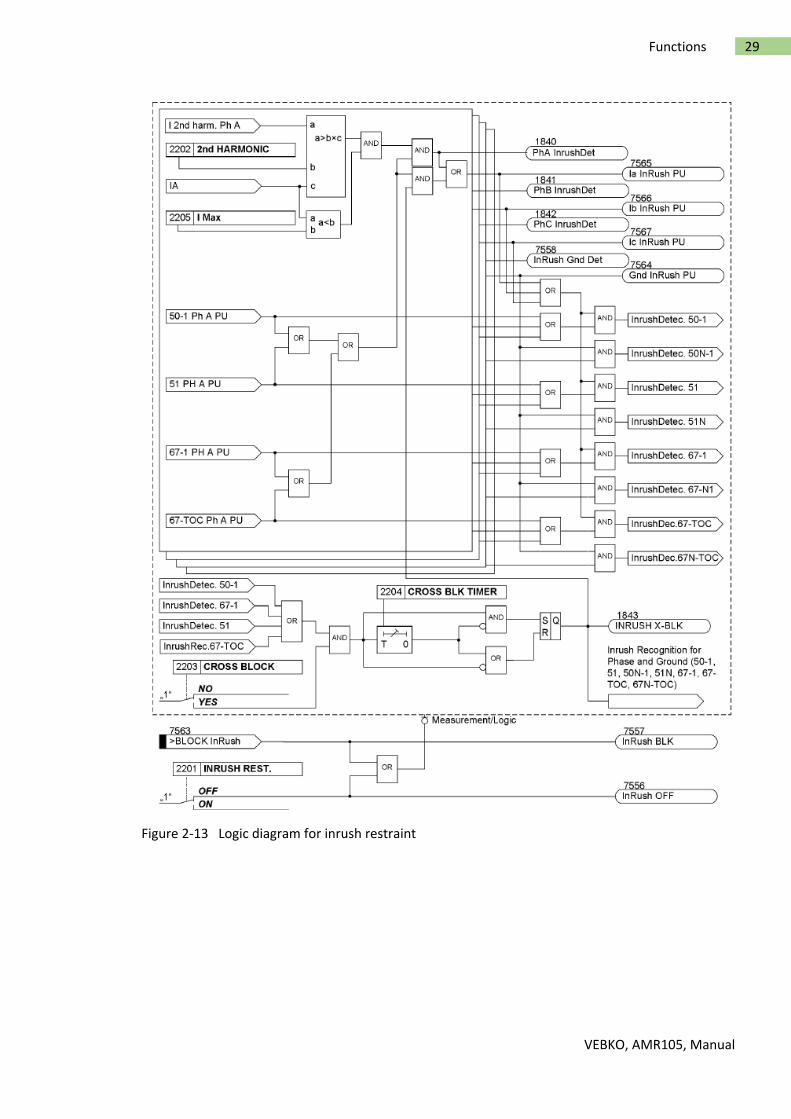
Inrush current is recognized if the following conditions are fulfilled at the same time:
The harmonic content is larger than the setting value 2202 2nd HARMONIC (minimum 0.125
* INom,sec);
the currents do not exceed an upper limit value 2205 I Max;
an exceeding of a threshold value via an inrush restraint of the blocked element takes place.
In this case an inrush in the affected phase is recognized (annunciations 1840 to 1842 and 7558
„InRush GndDet“ , and its blocking being carried out.
Since quantitative analysis of the harmonic components cannot be completed until a full line period
has been measured, pickup will generally be blocked by then. Therefore, assuming the inrush
restraint feature is enabled, a pickup message will be delayed by a full line period if no closing process
is present. On the other hand, trip delay times of the time overcurrent protection feature are started
immediately even with the inrush restraint being enabled. Time delays continue running with inrush
currents present. If inrush blocking drops out after the time delay has elapsed, tripping will occur
immediately. Therefore, utilization of the inrush restraint feature will not result in any additional
tripping delays. If a relay element drops out during inrush blocking, the associated time delay will
reset.
Cross Blocking

VEBKO, AMR105, Manual
28 Functions
Since inrush restraint operates individually for each phase, protection is ideal where a power
transformer is energized into a single-phase fault and inrush currents are detected on a different
healthy phase. However, the protection feature can be configured to allow that not only this phase
element but also the remaining elements (including ground) are blocked (the so-called CROSS BLOCK
function, address 2203) if the permissible harmonic component of the current is exceeded for only
one phase.
Please take into consideration that inrush currents flowing in the ground path will not cross-block
tripping by the phase elements.
Cross blocking is reset if there is no more inrush in any phase. Furthermore, the cross blocking
function may also be limited to a particular time interval (address 2204 CROSS BLK TIMER ). After
expiry of this time interval, the cross blocking function will be disabled, even if inrush current is still
present.
The inrush restraint has an upper limit: Above this (via adjustable parameter 2205 I Max) current
blocking is suppressed since a high-current fault is assumed in this case.
The following figure shows the inrush restraint influence on the time overcurrent elements including
crossblocking.
VEBKO, AMR105, Manual
29 Functions
Figure 2-13 Logic diagram for inrush restraint
VEBKO, AMR105, Manual
30 Functions
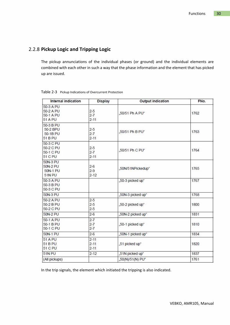
Pickup Logic and Tripping Logic
The pickup annunciations of the individual phases (or ground) and the individual elements are
combined with each other in such a way that the phase information and the element that has picked
up are issued.
Table 2-3 Pickup Indications of Overcurrent Protection
In the trip signals, the element which initiated the tripping is also indicated.

VEBKO, AMR105, Manual
31 Functions
Two-phase Overcurrent Protection (Only Non-Directional)
The 2-phase overcurrent protection functionality is used in isolated or grounded systems where
interaction with existing 2-phase protection equipment is required. As an isolated or grounded
system remains operational with a 1-phase ground fault, this protection serves to detect double
ground faults with high ground fault currents. measurement is sufficient for this purpose. In order to
ensure selectivity of the protection in this section of the system, only phases A and C are monitored.
If 250 250 50/51 2-ph prot (settable in P.System Data 1) is set to ON , IB is not used for threshold
comparison. If the fault is a simple ground fault in B, the element will not pick up. A double ground
fault is assumed only after pickup on A or C, causing the element to pick up and trip after the delay
time has elapsed.
Note
With inrush detection activated and inrush only on B, no cross blocking will take place in the other
phases. On the other hand, if inrush with cross blocking is activated on A or C, B will also be blocked.
Setting Notes
General
When selecting the time overcurrent protection in Software, a dialog box appears with several tabs
for setting the individual parameters. Depending on the functional scope specified during
configuration of the protection functions under addresses 112 Charac. Phase and 113 Charac.
Ground, the number of tabs can vary. If address FCT 50/51 was set to Definite Time, or Charac.
Ground was set to Definite Time, then only the settings for the definite time elements are available.
The selection of TOC IEC or TOC ANSI makes available additional inverse time characteristics. The
superimposed high-set elements 50-2, 50-3 or 50N-2, 50N-3 are available in all these cases.
Parameter 250 50/51 2-ph prot can also be set to activate two-phase overcurrent protection.
Under address 1201 FCT 50/51, overcurrent protection for phases and under address 1301 FCT
50N/51N,the ground overcurrent protection can be switched ON or OFF. Pickup values, time delays,
and characteristics for ground protection are set separately from the pickup values,time delays and
characteristic curves associated with phase protection. Because of this, relay coordination for ground
faults is independent of relay coordination for phase faults, and more sensitive settings can often be
applied to directional ground protection.
Depending on the setting of parameter 251 CT Connect., the device can also be used in specific
system configuration with regard to current connections.
Measurement Methods

VEBKO, AMR105, Manual
32 Functions
The comparison values to be used for the respective element can be set in the setting sheets for the
elements.
Measurement of the fundamental harmonic (standard method):
This measurement method processes the sampled values of the current and filters in
numerical order thefundamental harmonic so that the higher harmonics or transient peak
currents remain largely unconsidered.
Measurement of the true RMS value
The current amplitude is derived from the sampled values in accordance with the definition
equation of the true RMS value. This measurement method should be selected when higher
harmonics are to be considered by the function (e.g. in capacitor banks).
Measurement with instantaneous values
This procedure compares the instantaneous values to the set threshold. The element picks
up at 2 · √2 ·setting value (rms). It does not perform a mean-value calculation and is thus
sensitive with regard to disturbances.This measurement method should only be selected if
an especially short pickup time of the element is required. In this measurement procedure,
the operating time of the element is reduced compared to the measurement of effective
values or fundamental harmonics (see „Technical Data“).
The type of the comparison values can be set under the following addresses:
50-3 element Address 1219 50-3 measurem.
50-2 element Address 1220 50-2 measurem.
50-1 element Address 1221 50-1 measurem.
51 element Address 1222 51 measurem.
50N-3 element Address 1319 50N-3 measurem.
50N-2 element Address 1320 50N-2 measurem.
50N-1 element Address 1321 50N-1 measurem.
51N element Address 1322 51N measurem.
High-set Current Elements 50-2, 50-3 (phases)
The pickup current of the high-set element 50-2 PICKUP or 50-3 PICKUP can be set at address 1202
or 1207. The corresponding delay time 50-2 DELAY or 50-3 DELAY can be configured under
address1203 or 1218. It is usually used for purposes of current grading intended for large impedances
that are prevalent in transformers or generators. It is specified in such manner that it picks up faults
up to this impedance.
Example of the high-set current element 50-2 PICKUP: Transformer used for busbar supply with the
following data:

VEBKO, AMR105, Manual
33 Functions
Rated apparent power SNomT = 16 MVA
Transformer impedance ZT = 10 %
Primary nominal voltage VNom1 = 110 kV
Secondary nominal voltage VNom2 = 20 kV
Vector groups Dy 5
Neutral point Grounded
Fault power on 110 kV-side 1 GVA
Based on the data above, the following fault currents are calculated:
Three-Phase High Voltage Side Fault Current at 110 kV = 5250 A
Three-Phase Low Voltage Side Fault Current at 20 kV = 3928 A
On the High Voltage Side Flowing at 110 kV = 714 A
The nominal current of the transformer is:
INomT, 110 = 84 A (High Voltage Side) INomT, 20 = 462 A (Low VoltageSide)
Current Transformer (High Voltage Side) 100 A/1 A
Current Transformer (Low Voltage Side) 500 A/1 A
the following setting applies to the protection device: The 50-2 high-set current element must be set
higher than the maximum fault current which is detected during a low side fault on the high side. To
reduce fault probability as much as possible even when fault power varies, the following setting is
selected in primary values: 50-2 /INom= 10, i.e. 50-2 = 1000 A. The same applies analogously when
using the high-set element 50-3.
Increased inrush currents, if their fundamental component exceeds the setting value, are rendered
harmless by delay times (address 1203 50-2 DELAY or 1218 50-3 DELAY).
For motor protection, the 50-2 relay element must be set smaller than the smallest phase-to-phase
fault current and larger than the largest motor starting current. Since the maximum occurring startup
current is usually below 1.6 x the rated startup current (even with unfavourable conditions), the
following setting is adequate for thefault current element 50-2:
1.6 x IStartup < 50-2 Pickup< Ifault,2pole,min

VEBKO, AMR105, Manual
34 Functions
The potential increase in starting current caused by overvoltage conditions is already accounted for
by the 1.6 factor. The 50-2 element can be tripped without delay (50-2 DELAY = 0.00 s), since
saturation of the shunt reactance occurs in a motor, unlike in a transformer, for example.
The principle of the "reverse interlocking" utilizes the multi-element function of the time overcurrent
protection:Element 50-2 PICKUP is applied as a fast busbar protection with a shorter safety delay
time 50-2 DELAY(e.g. 100 ms). For faults at the outgoing feeders, element 50-2 is blocked. The
elements 50-1 or 51 serve as backup protection. The pickup values of both elements (50-1 PICKUP or
51 PICKUP and 50-2 PICKUP) are set equal. The delay time 50-1 DELAY or 51 TIME DIAL is set in such
manner that it overgrades the delay for the outgoing feeders.
The selected time is an additional delay time and does not include the operating time (measuring
time, dropout time). The delay can also be set to ∞. In this case, the element will not trip after pickup.
However, pickup, will be signaled. If the 50-2 element or the 50-3 element is not required at all, the
pickup threshold 50-2 or 50-3 is set to ∞. This setting prevents tripping and the generation of a
pickup message.
High-set Current Elements 50N-2, 50N-3 (ground)
The pickup current of the high-set element 50N-2 PICKUP or 50N-3 PICKUP can be set at address 1302
or1317. The corresponding delay time 50N-2 DELAY or 50N-3 DELAY can be configured under address
1303 or 1318. The same considerations apply to these settings as they did for phase currents
discussed earlier.
The selected time is an additional delay time and does not include the operating time (measuring
time, dropout time). The delay can also be set to ∞. In this case, the element will not trip after pickup.
However, pickup, will be signaled. If the 50N-2 element or 50N-3 element is not required at all, the
pickup threshold 50N-2 or 50N-3 should be set to ∞. This setting prevents tripping and the
generation of a pickup message.
50-1 Element (phases)
For setting the 50-1 element, it is the maximum anticipated load current that must be considered
above all. Pickup due to overload should never occur since in this mode the device operates as fault
protection with correspondingly short tripping times and not as overload protection. For this reason,
a setting equal to 20% of the expected peak load is recommended for line protection, and a setting
equal to 40% is recommended for transformers and motors.
The settable time delay (address 1205 50-1 DELAY) results from the grading coordination chart
defined for the system.
The selected time is an additional delay time and does not include the operating time (measuring
time, dropout time). The delay can also be set to . In this case, the element will not trip after
pickup. However, pickup, will be signaled. If the 50-1 element is not required at all, then the pickup
threshold 50-1 should be set to . This setting prevents tripping and the generation of a pickup
message.
50N-1 Element (ground)
VEBKO, AMR105, Manual
35 Functions
The 50N-1 element is normally set based on minimum ground fault current.
If the relay is used to protect transformers or motors with large inrush currents, the inrush restraint
feature of AMR105 may be used for the 50N-1 relay element. It can be enabled or disabled for both
the phase current and the ground current in address 2201 INRUSH REST.. The characteristic values
of the inrush restraint are listed in Subsection "Inrush Restraint".
The settable delay time (address 1305 50N-1 DELAY) results from the time coordination chart defined
for the system. For ground currents in a grounded system a separate coordination timer with short
time delays can be applied.
The selected time is an additional delay time and does not include the operating time (measuring
time, dropout time). The delay can also be set to . In this case, the element will not trip after
pickup. However, pickup, will be signaled. If the 50N-1 element is not required at all, the pickup
threshold 50N-1 PICKUP should be set to . This setting prevents tripping and the generation of a
pickup message.
Pickup Stabilization (Definite Time)
The configurable dropout times 1215 50 T DROP-OUT or 1315 50N T DROP-OUT can be set to
implement a uniform dropout behavior when using electromechanical relays. This is necessary for a
time grading. The dropout time of the electromechanical relay must be known to this end. Subtract
the dropout time of the device (see Technical Data) from this value and enter the result in the
parameters.
51 Element (phases) with IEC or ANSI characteristics
Having set address 112 Charac. Phase = TOC IEC or TOC ANSI when configuring the protection
functions (Section 2.1.1.2), the parameters for the inverse time characteristics will also be available.
If address 112 Charac. Phase was set to TOC IEC, you can select the desired IEC characteristic (Normal
Inverse, Very Inverse, Extremely Inv. or Long Inverse) at address 1211 51 IEC CURVE. If address 112
Charac. Phase was set to TOC ANSI, you can select the desired ANSI characteristic (Very Inverse,
Inverse, Short Inverse, Long Inverse, Moderately Inv., Extremely Inv. orDefinite Inv.) at address 1212
51 ANSI CURVE.
If the inverse time trip characteristic is selected, it must be noted that a safety factor of about 1.1
has already been included between the pickup value and the setting value. This means that a pickup
will only occur if a current of about 1.1 times the setting value is present. If Disk Emulation was
selected at address0 1210 51Drop-out , reset will occur in accordance with the reset curve as
described before.
The current value is set in address 1207 51 PICKUP. The setting is mainly determined by the maximum
anticipated operating current. Pickup due to overload should never occur since in this mode, the
device operates as fault protection with correspondingly short tripping times and not as overload
protection.

VEBKO, AMR105, Manual
36 Functions
The corresponding time multiplier for an IEC characteristic is set at address 1208 51 TIME DIAL and
in address1209 51 TIME DIAL for an ANSI characteristic. It must be coordinated with the time
coordination chart of the system.
The time multiplier can also be set to . In this case, the element will not trip after pickup. However,
pickup will be signaled.If the 51 element is not required at all, address112 Charac. Phase should be
set to DefiniteTime during protection function configuration.
If highly sensitive settings close to the load current are required in weak power systems or
transformers, the element can be stabilized via the undervoltage as an additional criterion for the
power system fault. The operating modes can be set in address1223 VOLT. INFLUENCE. In a voltage-
controlled operation, the voltage threshold is defined via parameter1224 51V V< below which the
current element is released.
51N Element (ground) with IEC or ANSI Characteristics
Having set address 113 Charac. Ground = TOC IEC when configuring the protection functions, the
parameters for the inverse time characteristics will also be available. Specify in address 1311 51N IEC
CURVE the desired IEC characteristic (Normal Inverse, Very Inverse, Extremely Inv. or Long Inverse).
If address 113 Charac. Ground was set to TOC ANSI, you can select the desired ANSI characteristic
(Very Inverse, Inverse, Short Inverse, Long Inverse, Moderately Inv.,Extremely Inv. or Definite Inv.) in
address 1312 51N ANSI CURVE.
If the inverse time trip characteristic is selected,it must be noted that a safety factor of about 1.1 has
already been included between the pickup value and the setting value. This means
that a pickup will only occur if a current of about 1.1 times the setting value is present.If Disk
Emulation was selected at address 1310 51Drop-out, reset will occur in accordance with the reset
curve as described before.
The current value is set in address1307 51N PICKUP. The setting is mainly determined by the
minimum anticipated ground fault current.
The corresponding time multiplier for an IEC characteristic is set at address1308 51N TIME DIAL and
at Address 1309 51N TIME DIAL for an ANSI characteristic. This has to be coordinated with the grading
coordination chart of the network. For ground currents with grounded network, you can often set up
a separate grading coordination chart with shorter delay times.
The time multiplier can also be set to . In this case, the element will not trip after pickup. However,
pickup will be signaled. If the 51N-TOC element is not required at all, address 113 Charac. Ground
should be set to Definite Time during configuration of the protection functions.
User-defined Characteristics (phases and ground)
Having set address 112 Charac. Phase or 113 = Charac. Ground = User Defined PU or User def.Reset
when configuring the protection functions, user-defined curves will also be available. A maximum of
20 value pairs (current and time) may be entered at address 1230 51/51N or 1330 50N/51N in this
case. This option allows point-by-point entry of any desired curve. When setting address 112 = User

VEBKO, AMR105, Manual
37 Functions
def. Reset or 113 = User def. Reset, additional value pairs (current and reset time) may be entered in
address 1231 MofPU Res T/Tp or 1331 MofPU Res T/TEp to represent the dropout curve.
Since current values are rounded in a specific pattern before they are processed in the device , we
recommend to use exactly the same preferred current values you can find in this table.
The current and time value pairs are entered as multiples of addresses 1207 51 PICKUP and 1208 51
TIMEDIAL for the phase currents and1307 and 1308 for the ground system. Therefore, it is
recommended that these addresses are initially set to 1.00 for simplicity. Once the curve is entered,
the values at addresses 1207 or 1307 or/and 1208 or 1308 can be modified later to allow moving the
curve in a different direction.
The default setting of current values is . They are, therefore, disabled and no pickup or tripping of
these protection functions will occur.
The following must be observed:
The value pairs should be entered in increasing sequence. If desired, fewer than 20 pairs
can be entered. In most cases, about 10 pairs is sufficient to define the characteristic
accurately. A value pair which is not used has to be made invalid by entering " ” for the
threshold! The user must ensure that the value pairs produce a clear and constant
characteristic .
The current values entered should be those from the following table, along with the
matching times. Deviating values MofPU (multiples of PU-values) are rounded. This,
however, will not be indicated. Currents smaller than the current value of the smallest curve
point will not lead to an extension of the tripping time. The pickup curve runs parallel to the
current axis, up to the smallest current value point.
Currents larger than the largest current value entered will not lead to a reduction of the
tripping time. The pickup curve runs parallel to the current axis, beginning with the greatest
current value point.
Table 2-4 Preferential values of standardized currents for user-defined tripping curves
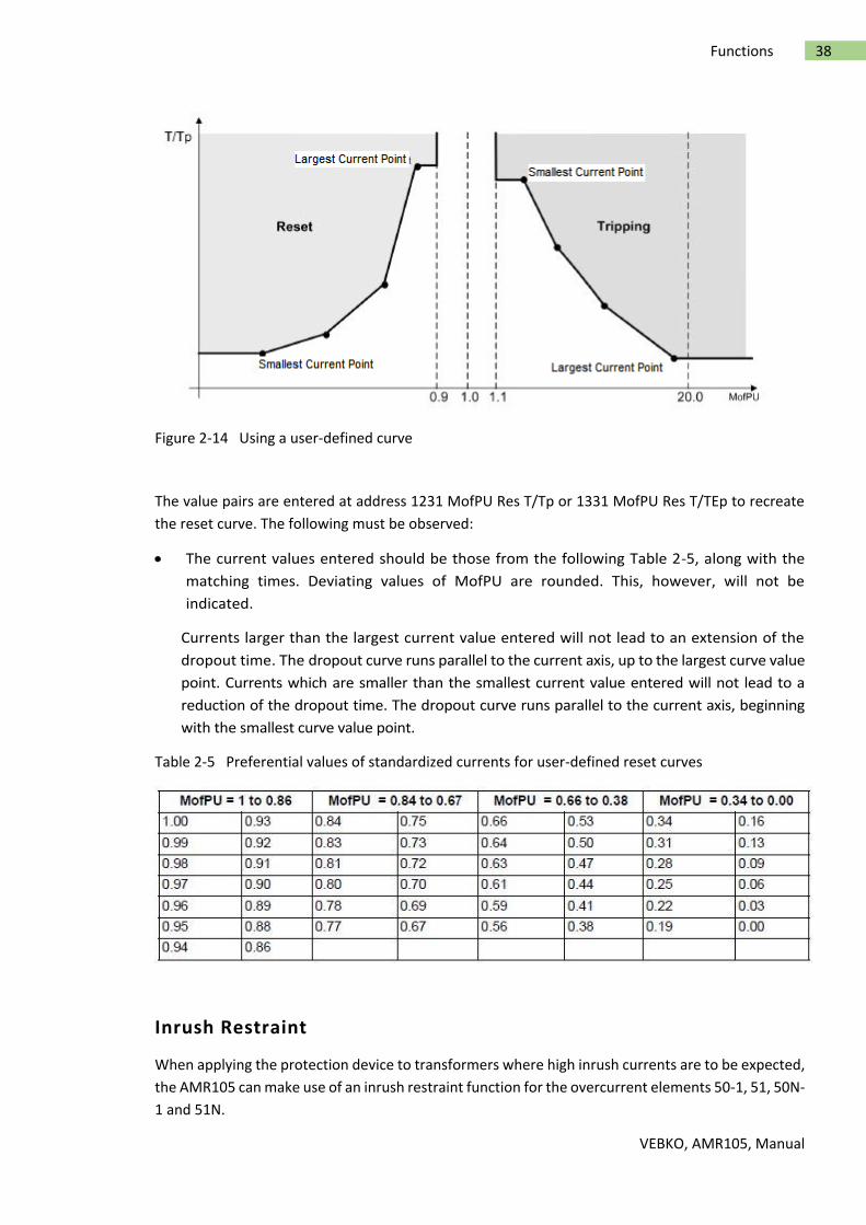
VEBKO, AMR105, Manual
38 Functions
Figure 2-14 Using a user-defined curve
The value pairs are entered at address 1231 MofPU Res T/Tp or 1331 MofPU Res T/TEp to recreate
the reset curve. The following must be observed:
The current values entered should be those from the following Table 2-5, along with the
matching times. Deviating values of MofPU are rounded. This, however, will not be
indicated.
Currents larger than the largest current value entered will not lead to an extension of the
dropout time. The dropout curve runs parallel to the current axis, up to the largest curve value
point. Currents which are smaller than the smallest current value entered will not lead to a
reduction of the dropout time. The dropout curve runs parallel to the current axis, beginning
with the smallest curve value point.
Table 2-5 Preferential values of standardized currents for user-defined reset curves
Inrush Restraint
When applying the protection device to transformers where high inrush currents are to be expected,
the AMR105 can make use of an inrush restraint function for the overcurrent elements 50-1, 51, 50N-
1 and 51N.

VEBKO, AMR105, Manual
39 Functions
Inrush restraint is only effective and accessible if address 122 InrushRestraint was set to Enabled. If
this function is not required, then Disabled is set. In address 2201 INRUSH REST., the function is
switched ON or OFF jointly for the overcurrent elements 50-1 PICKUP, 51 PICKUP, 50N-1 PICKUP, and
51N PICKUP.
The inrush restraint is based on the evaluation of the 2nd harmonic present in the inrush current.
Upon delivery from the factory, a ratio I2f/If of 15 % is set. Under normal circumstances, this setting
will not need to be changed. The setting value is identical for all phases and ground. However, the
component required for restraint may be adjusted to system conditions in address 2202 2nd
HARMONIC. To provide more restraint in exceptional cases, where energizing conditions are
particularly unfavorable, a smaller value can be set in the aforementioned address, e.g. 12 %.
Irrespective of parameter 2202 2nd HARMONIC, rush blocking will only occur if the absolute value of
the 2nd harmonic is at least 0.125 * INom,sec.
The effective duration of the cross-blocking 2203 CROSS BLK TIMER can be set to a value between 0
s (harmonic restraint active for each phase individually) and a maximum of 180 s (harmonic restraint
of a phase blocks also the other phases for the specified duration).
If the current exceeds the value set in address 2205 I Max, no further restraint will take place for the
2nd harmonic.
Manual Close Mode (phases,ground)
When a circuit breaker is closed onto a faulted line, a high-speed trip by the circuit breaker is usually
desired. For overcurrent or high-set element the delay may be bypassed via a Manual Close pulse,
thus resulting in instantaneous tripping. This pulse is prolonged by at least 300 ms. To enable the
device to react properly on occurrence of a fault in the phase element, address 1213 MANUAL CLOSE
has to be set accordingly. Correspondingly, address 1313 MANUAL CLOSE is considered for the
ground path address. Thus, the user determines for both elements, the phase and the ground
element, what pickup value is active with what delay when the circuit breaker is closed manually.
External Control Command
If the manual close signal is not sent from AMR105 device, i.e. neither via the built-in operator
interface nor via a serial interface, but directly from a control acknowledgment switch, this signal
must be passed to a AMR105 binary input, and configured accordingly („>Manual Close “), so that
the element selected for MANUAL CLOSE can become effective. The alternative Inactive means that
all elements operate as per configuration even with manual close and do not get special treatment.
Interaction with the Automatic Reclosing Function (phases)
If reclosing follows, high-speed and simultaneous protection against faults with 50-2 or 50-3 is usually
desired. If the fault still exists after the first reclosing, the 50-1 or the 51 element will be initiated
with graded tripping times, that is, element 50-2 or 50-3 will be blocked. You can use the parameters
1214 50-2 active or1216 50-3 active for this purpose to define whether or not the 50-2 or the 50-3
element is impacted by a release signal of the internal or an external automatic reclosing system. The
setting with 79 active means that the 50-2 or the 50-3 element will only be released if automatic

VEBKO, AMR105, Manual
40 Functions
reclosing is not blocked. If this is not desired, the setting Always is selected so that the 50-2 or the
50-3 element is always active.
The integrated automatic reclosing function of AMR105 also provides the option to individually
determine for each overcurrent element whether tripping or blocking is to be carried out
instantaneously or unaffected by the AR with the set time delay.
Interaction with the Automatic Reclosing Function (ground)
When reclosing occurs, it is desirable to have high-speed protection against faults with 50N-2 or 50N-
3. If the fault still exists after the first reclosing, the 50N-1 or the 51N element will be initiated with
coordinated tripping times, that is, element 50N-2 or 50N-3 will be blocked. At address 1314 50N-2
active or 1316 50N-3 active it can be specified whether the 50N-2 or the 50N-3 element should be
influenced by the release signal of an internal or external automatic reclosing system. Address with
79 active determines that the 50N-2 or the 50N-3 element will only operate if automatic reclosing is
not blocked.If not desired, select the setting Always so that the 50N-2 or the 50N-3 element will
always operate, as configured.
The integrated automatic reclosing function of AMR105 also provides the option to individually
determine for each overcurrent element whether tripping or blocking is to be carried out
instantaneously or unaffected by the AR with the set time delay.
Settings
The table indicates region-specific default settings. Column C (configuration) indicates the
corresponding secondary nominal current of the current transformer.
Adr. Parameter C Setting options Default Setting
1201 50,51 Phase time Overcurrent ON OFF
ON
1213 Manual Close Mode 50/51 50-1 instantaneously 50-2 instantaneously 50-3 instantaneously 51 instanteneously Inactive
50-2 instantaneously
1215 50 Drop-out Time Delay 0.00:0.01:60.00[sec] 0.00
1301 50N, 51N Ground Time Overcurrent ON OFF
ON
1313 Manusal Close Mode 50N/51N 50N-1 instantaneously 50N-2 instantaneously 50N-3 instantaneously 51N instanteneously Inactive
50N-2 instantaneously
1315 50N Drop-out Time Delay 0.00:0.01:60.00[sec] 0.00
1219 50-3 measurement of Fundamental component True RMS Instantaneous Value
Fundamental component
1216 50-3 active Always With 79 Active
Always
1217 50-3 Pickup 1A 1.00:0.01:35.00,oo[A] oo

VEBKO, AMR105, Manual
41 Functions
9807 50-3 Pickup 5A 5.00:0.01:175.00,oo[A] oo
1218 50-3 Time Delay 0.00:0.01:60.00,oo(inactive)[sec] 0.00
1220 50-2 measurement of Fundamental component True RMS
Fundamental component
1214 50-2 active Always With 79 Active
Always
1202 50-2 Pickup 1A 0.10:0.01:35.00,oo(inactive)[A] 2.00
9808 50-2 Pickup 5A 0.50:0.01:175.00,oo(inactive)[A] 5.00
1203 50-2 Time Delay 0.00:0.01:60.00,oo(inactive)[sec] 0.00
1221 50-1 measurement of Fundamental component True RMS
Fundamental component
1204 50-1 Pickup 1A 0.10:0.01:35.00,oo(inactive)[A] 1.00
9809 50-1 Pickup 5A 0.50:0.01:175.00,oo(inactive)[A] 5.00
1205 50-1 Time Delay 0.00:0.01:60.00,oo(inactive)[sec] 0.50
1222 51 measurement of Fundamental component True RMS
Fundamental component
1207 51 Pickup 1A 0.10:0.01:4.00,oo(inactive)[A] 1.00
9810 51 Pickup 5A 0.50:0.01:20.00,oo(inactive)[A] 1.00
1208 51 Time Dial IEC 0.05:0.01:3.20,oo[] 0.05
1209 51 Time Dial ANSI 0.50:0.01:15.00,oo[] 5.00
1210 Drop-out characteristic Disk Emulation Inatantaneous
Inatantaneous
1211 IEC Curve Normal Inverse Very Inverse Extremely Inverse Long Inverse
Normal Inverse
1212 ANSI Curve Inverse Very Inverse Extremely Inverse Moderately Inverse Short Inverse Long Inverse Definite Inverse
Very Inverse
1223 51V Voltage Influence NO Voltage Controlled Voltage Restraint
NO
1224 51V V<Threshold for Release Ip 10.0:0.1:125.0[V] 75.0
1319 50N-3 measurement of Fundamental component True RMS Instantaneous Value
Fundamental component
1316 50N-3 active Always With 79 Active
Always
1323 50N-3 Pickup 1A Sens.
0.25:0.01:35.00,oo[A] oo
1317 50N-3 Pickup 5A 0.25:0.01:175.00,oo[A] oo
1318 50N-3 Time Delay 0.00:0.01:60.00,oo(inactive)[sec] 0.00
1320 50N-2 measurement of Fundamental component True RMS
Fundamental component
1314 50N-2 active Always With 79 Active
Always
1302 50N-2 Pickup 1A Sens.
0.05:0.01:35.00,oo[A] 0.50
9811 50N-2 Pickup 5A 0.25:0.01:175.00,oo[A] 0.50
1303 50N-2 Time Delay 0.00:0.01:60.00,oo(inactive)[sec] 0.10
1321 50N-1 measurement of Fundamental component True RMS
Fundamental component

VEBKO, AMR105, Manual
42 Functions
1304 50N-1 Pickup 1A Sens.
0.05:0.01:35.00,oo[A] 0.20
9812 50N-1 Pickup 5A 0.25:0.01:175.00,oo[A] 0.25
1305 50N-1 Time Delay 0.00:0.01:60.00,oo(inactive)[sec] 0.50
1322 51N measurement of Fundamental component True RMS
Fundamental component
1307 51N Pickup 1A Sens.
0.05:0.01:4.00[A] 0.20
9996 51N Pickup 5A 0.25:0.01:20.00[A] 0.25
1308 51N Time Dial IEC 0.05:0.01:3.20,oo[] 0.05
1309 51N Time Dial ANSI 0.50:0.01:15.00,oo[] 5.00
1310 Drop-out characteristic Disc Emulation Inatantaneous
Inatantaneous
1311 IEC Curve Normal Inverse Very Inverse Extremely Inverse Long Inverse
Normal Inverse
1312 ANSI Curve Inverse Very Inverse Extremely Inverse Moderately Inverse Short Inverse Long Inverse Definite Inverse
Very Inverse
Information List
No. Information Type of Information Comments.
100097 >BLK 50/51 SP >BLOCK 50/51
100098 >BLK 50N/51N SP >BLOCK 50N/51N
100099 >BLOCK 50-3 SP >BLOCK 50-3
100100 >BLOCK 50N-3 SP >BLOCK 50N-3
100101 >BLOCK 50-2 SP >BLOCK 50-2
100102 >BLOCK 50-1 SP >BLOCK 50-1
100103 >BLOCK 51 SP >BLOCK 51
100104 >BLOCK 50N-2 SP >BLOCK 50N-2
100105 >BLOCK 50N-1 SP >BLOCK 50N-1
100106 >BLOCK 51N SP >BLOCK 51N
100107 50/51 PH OFF OUT 50/51 O/C switched OFF
100108 50/51 PH BLK OUT 50/51 O/C is BLOCKED
100109 50/51 PH ACT OUT 50/51 O/C is ACTIVE
100110 50N/51N OFF OUT 50N/51N switched OFF
100111 50N/51N BLK OUT 50N/51N is BLOCKED
100112 50N/51N ACT OUT 50N/51N is ACTIVE
100113 50(N)/51(N) PU OUT 50(N)/51(N) O/C PICKUP
100114 50/51 Ph A PU OUT 50/51 Phase A picked up
100115 50/51 Ph B PU OUT 50/51 Phase B picked up
100116 50/51 Ph C PU OUT 50/51 Phase C picked up
100117 50N/51NPickedup OUT 50N/51N picked up
100118 50-3 picked up OUT 50-3 picked up
100119 50N-3 picked up OUT 50N-3 picked up
100120 50-3 TRIP OUT 50-3 TRIP

VEBKO, AMR105, Manual
43 Functions
100121 50N-3 TRIP OUT 50N-3 TRIP
100122 50-3 TimeOut OUT 50-3 TimeOut
100123 50N-3 TimeOut OUT 50N-3 TimeOut
100124 50(N)/51(N)TRIP OUT 50(N)/51(N) TRIP
100125 50-2 picked up OUT 50-2 picked up
100126 50-2 TimeOut OUT 50-2 Time Out
100127 50-2 TRIP OUT 50-2 TRIP
100128 50-1 picked up OUT 50-1 picked up
100129 50-1 TimeOut OUT 50-1 Time Out
100130 50-1 TRIP OUT 50-1 TRIP
100131 51 picked up OUT 51 picked up
100132 51 Time Out OUT 51 Time Out
100133 51 TRIP OUT 51 TRIP
100134 50N-2 picked up OUT 50N-2 picked up
100135 50N-2 TimeOut OUT 50N-2 Time Out
100136 50N-2 TRIP OUT 50N-2 TRIP
100137 50N-1 picked up OUT 50N-1 picked up
100138 50N-1 TimeOut OUT 50N-1 Time Out
100139 50N-1 TRIP OUT 50N-1 TRIP
100140 51N picked up OUT 51N picked up
100141 51N TimeOut OUT 51N Time Out
100142 51N TRIP OUT 51N TRIP
100143 PhA InrushDet OUT Phase A inrush detection
100144 PhB InrushDet OUT Phase B inrush detection
100145 PhC InrushDet OUT Phase C inrush detection
100146 INRUSH X-BLK OUT Cross blk: PhX blocked PhY
100147 50-1 BLOCKED OUT 50-1 BLOCKED
100148 50-2 BLOCKED OUT 50-2 BLOCKED
100149 50N-1 BLOCKED OUT 50N-1 BLOCKED
100150 50N-2 BLOCKED OUT 50N-2 BLOCKED
100151 51 BLOCKED OUT 51 BLOCKED
100152 51N BLOCKED OUT 51N BLOCKED
100153 50-1 InRushPU OUT 50-1 InRush picked up
100154 50N-1 InRushPU OUT 50N-1 InRush picked up
100155 51 InRushPU OUT 51 InRush picked up
100156 51N InRushPU OUT 51N InRush picked up
100157 InRush OFF OUT InRush OFF
100158 InRush BLK OUT InRush BLOCKED
100159 InRush Gnd Det OUT InRush Ground detected
100160 67-1 InRushPU OUT 67-1 InRush picked up
100161 67N-1 InRushPU OUT 67N-1 InRush picked up
100162 67-TOC InRushPU OUT 67-TOC InRush picked up
100163 67N-TOCInRushPU OUT 67N-TOC InRush picked up
100164 >BLOCK InRush SP >BLOCK InRush
100165 Gnd InRush PU OUT Ground InRush picked up
100166 Ia InRush PU OUT Phase A InRush picked up
100167 Ib InRush PU OUT Phase B InRush picked up
100168 Ic InRush PU OUT Phase C InRush picked up
100169 50-3 BLOCKED OUT 50-3 BLOCKED
100170 50N-3 BLOCKED OUT 50N-3 BLOCKED
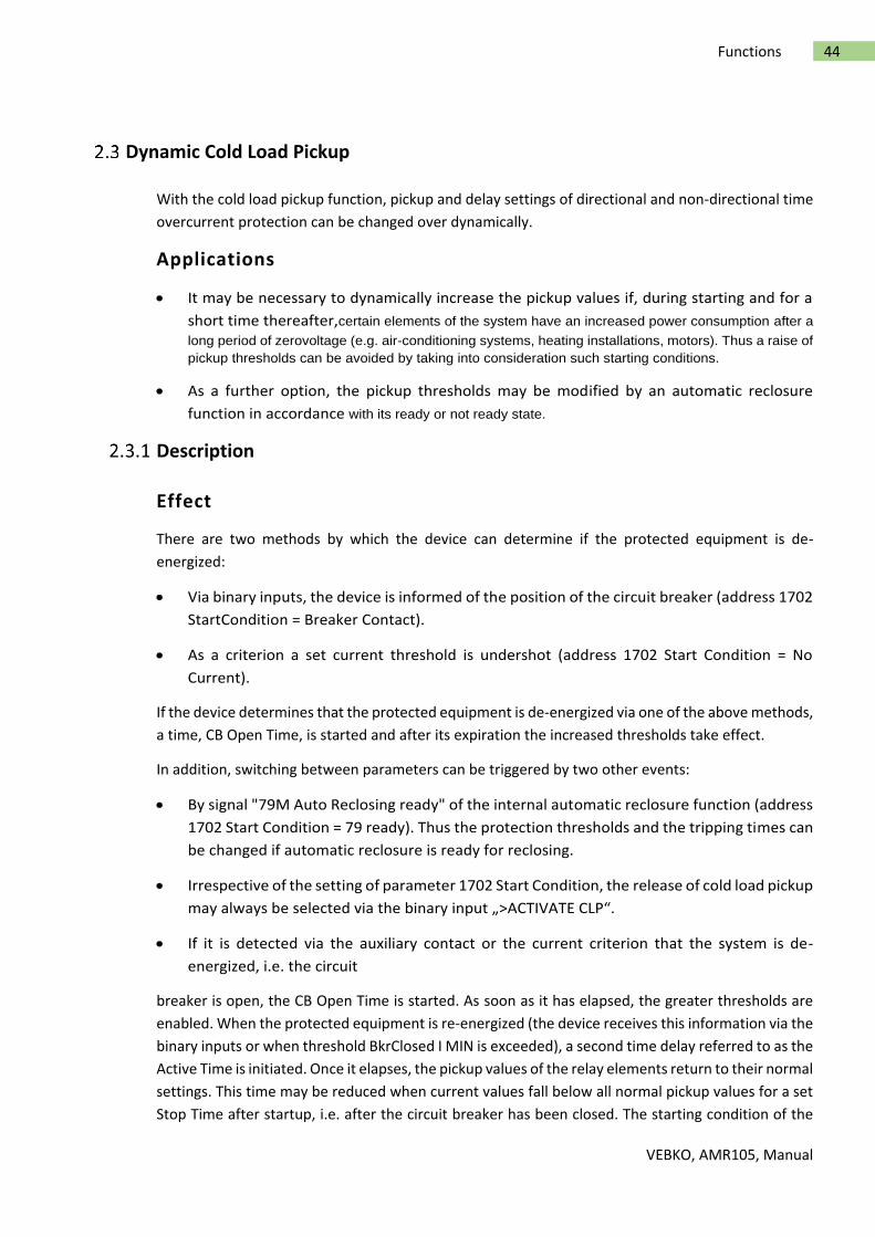
VEBKO, AMR105, Manual
44 Functions
Dynamic Cold Load Pickup
With the cold load pickup function, pickup and delay settings of directional and non-directional time
overcurrent protection can be changed over dynamically.
Applications
It may be necessary to dynamically increase the pickup values if, during starting and for a
short time thereafter,certain elements of the system have an increased power consumption after a
long period of zerovoltage (e.g. air-conditioning systems, heating installations, motors). Thus a raise of
pickup thresholds can be avoided by taking into consideration such starting conditions.
As a further option, the pickup thresholds may be modified by an automatic reclosure
function in accordance with its ready or not ready state.
Description
Effect
There are two methods by which the device can determine if the protected equipment is de-
energized:
Via binary inputs, the device is informed of the position of the circuit breaker (address 1702
StartCondition = Breaker Contact).
As a criterion a set current threshold is undershot (address 1702 Start Condition = No
Current).
If the device determines that the protected equipment is de-energized via one of the above methods,
a time, CB Open Time, is started and after its expiration the increased thresholds take effect.
In addition, switching between parameters can be triggered by two other events:
By signal "79M Auto Reclosing ready" of the internal automatic reclosure function (address
1702 Start Condition = 79 ready). Thus the protection thresholds and the tripping times can
be changed if automatic reclosure is ready for reclosing.
Irrespective of the setting of parameter 1702 Start Condition, the release of cold load pickup
may always be selected via the binary input „>ACTIVATE CLP“.
If it is detected via the auxiliary contact or the current criterion that the system is de-
energized, i.e. the circuit
breaker is open, the CB Open Time is started. As soon as it has elapsed, the greater thresholds are
enabled. When the protected equipment is re-energized (the device receives this information via the
binary inputs or when threshold BkrClosed I MIN is exceeded), a second time delay referred to as the
Active Time is initiated. Once it elapses, the pickup values of the relay elements return to their normal
settings. This time may be reduced when current values fall below all normal pickup values for a set
Stop Time after startup, i.e. after the circuit breaker has been closed. The starting condition of the

VEBKO, AMR105, Manual
45 Functions
fast reset time is made up of an OR-combination of the configured dropout conditions of all
directional and non-directional overcurrent elements. When Stop Time is set to ∞ or when binary
input „>BLK CLP stpTim“ is active, no comparison is made with the "normal" thresholds. The function
is inactive and the fast reset time, if applied, is reset.
If overcurrent elements are picked up while time Active Time is running, the fault generally prevails
until pickup drops out, using the dynamic settings. Only then the parameters are set back to
"normal".
If the dynamic setting values were activated via the binary input „>ACTIVATE CLP“ or the signal "79M
Auto Reclosing ready" and this cause drops out, the "normal" settings are restored immediately, even
if a pickup is the result.
If the binary input „>BLOCK CLP“ is enabled, all triggered timers are reset and, as a consequence, all
"normal" settings are immediately restored. If blocking occurs during an on-going fault with dynamic
cold load pickup functions enabled, the timers of all overcurrent relay elements are stopped and may
then be restarted based on their "normal" duration.
During power up of the protective relay with an open circuit breaker, the time delay CB Open Time
is started,and is processed using the "normal" settings. Therefore, when the circuit breaker is closed,
the "normal" settings are effective.
Figure 2-15 Timing charts of the dynamic cold load pickup function

VEBKO, AMR105, Manual
46 Functions
Figure 2-16 Logic diagram of the dynamic cold load pickup function (50c, 50Nc, 51c, 51Nc, 67c, 67Nc)
Setting Notes
General
The dynamic cold load pickup function can only be enabled if address 117 Coldload Pickup was set to
Enabled during configuration of the protection functions. If not required, this function is set to
Disabled. The function can be turned ON or OFF under address 1701 Coldload Pickup.
Depending on the condition that should initiate the cold load pickup function address 1702 Start
Condition is set to either No Current, Breaker Contact or to 79 ready. Naturally, the option Breaker
Contact can only be selected if the device receives information regarding the switching state of the
circuit breaker via at least one binary input. The option 79 ready modifies dynamically the pickup
thresholds of the directional and non-directional time overcurrent protection when the automatic

VEBKO, AMR105, Manual
47 Functions
reclosing function is ready. To initiate the cold load pickup, the automatic reclosing function provides
the internal signal "79M Auto Reclosing ready". It is always active when the automatic reclosing
function is available, activated, unblocked, and ready for a further cycle.
Time Delays
There are no specific procedures on how to set the time delays at addresses 1703 CB Open Time,
1704 Active Time and 1705 Stop Time. These time delays must be based on the specific loading
characteristics of the equipment being protected, and should be set to allow for brief overloads
associated with dynamic cold load conditions.
Non-Directional 50/51 Elements (phases)
The dynamic pickup values and tripping times associated with the time overcurrent protection
functions are set at address block 18 for the phase currents:
The dynamic pickup and delay settings for the high-set elements are set at addresses 1801 50c-2
PICKUP or 1808 50c-3 PICKUP and 1802 50c-2 DELAY or 1809 50c-3 DELAY respectively; the dynamic
pickup and delay settings for the 67N-1 element are set at addresses 1803 50c-1 PICKUP and 1804
50c-1 DELAY respectively; and the pickup, time multiplier (for IEC curves or user-defined curves), and
time dial (for ANSI curves) settings for the 67N-TOC element are set at addresses 1805 51c PICKUP,
1806 51c TIME DIAL and 1807 51c TIME DIAL respectively.
Non-Directional 50N/51N Elements (ground)
The dynamic pickup values and time delays associated with non-directional time overcurrent ground
protection are set at address block 19:
The dynamic pickup and delay settings for the high-set elements are set at addresses 1901 50Nc-2
PICKUP or 1908 50Nc-3 PICKUP and 1902 50Nc-2 DELAY or 1909 50Nc-3 DELAY respectively; the
dynamic pickup and delay settings for the 67N-1 element are set at addresses 1903 50Nc-1 PICKUP
and 1904 50Nc-1 DELAY respectively; and the pickup, time multiplier (for IEC curves or user-defined
curves), and time dial (forANSI curves) settings for the 67N-TOC element are set at addresses 1905
51Nc PICKUP, 1906 51Nc TDIAL and 1907 51Nc T-DIAL respectively.
Directional 67/67–TOC Elements (phases)
The dynamic pickup values and time delays associated with directional overcurrent phase protection
are set at address block 20:
Addresses 2001 67c-2 PICKUP or 2008 67c-3 PICKUP and 2002 67c-2 DELAY or 2009 67c-3 DELAY
define the dynamic parameters for the high-current elements, 2003 67c-1 PICKUP and 2004 67c-1
DELAY for the directional definite time overcurrent element and 2005 67c-TOC PICKUP in
combination with 2006 67c-TOC T-DIAL (for IEC characteristics or user-defined characteristics) or
2007 67c-TOC T-DIAL (for ANSI characteristics) for the directional inverse time overcurrent protection
element.
Directional 67/67N Elements (ground)

VEBKO, AMR105, Manual
48 Functions
The dynamic pickup values and time delays associated with directional overcurrent ground
protection are set at address block 21:
Addresses 2101 67Nc-2 PICKUP or 2108 67Nc-3 PICKUP and 2102 67Nc-2 DELAY or 2109 67Nc-3
DELAY define the dynamic parameters for the high-current elements, 2103 67Nc-1 PICKUP and 2104
67Nc-1 DELAY for the directional definite time overcurrent element and 2105 67Nc-TOC PICKUP in
combination with 2106 67Nc-TOC T-DIAL (for IEC characteristics or user-defined characteristics) or
2107 67Nc-TOC TDIAL (for ANSI characteristics) for the directional inverse time overcurrent
protection element.
Settings
The table indicates region-specific default settings. Column C (configuration) indicates the
corresponding secondary nominal current of the current transformer.
Adr. Parameter C Setting options Default Setting
1701 Cold-Load-Pickup Function ON OFF
OFF
1702 Start Condition No Current Breaker Contact 79M Auto Reclosing Ready
No Current
1703 Circuit Breker Open Time 0:1:21600[sec] 3600
1704 Active time 1:1:21600[sec] 3600
1705 Stop time 1:1:600,oo[sec] 600
1808 50c-3 Pickup 1A 1.00:0.01:35.00,oo(inactive)[A] oo
9820 50c-3 Pickup 5A 5.00:0.01:175.00,oo(inactive)[A] oo
1809 50c-3 Time Delay 0.00:0.01:60.00[sec] 0.00
1801 50c-2 Pickup 1A 1.00:0.01:35.00,oo(inactive)[A] 10.00
9821 50c-2 Pickup 5A 5.00:0.01:175.00,oo(inactive)[A] 10.00
1802 50c-2 Time Delay 0.00:0.01:60.00[sec] 0.00
1803 50c-1 Pickup 1A 1.00:0.01:35.00,oo(inactive)[A] 2.00
9822 50c-1 Pickup 5A 5.00:0.01:175.00,oo(inactive)[A] 5.00
1804 50c-1 Time Delay 0.00:0.01:60.00[sec] 0.30
1805 51c Pickup 1A 0.10:0.01:4.00,oo(inactive)[A] 1.50
9823 51c Pickup 5A 0.50:0.01:20.00,oo(inactive)[A] 1.50
1806 51c Time Dial IEC 0.05:0.01:3.20,oo[] 0.50
1807 51c Time Dial ANSI 0.50:0.01:15.00,oo[] 5.00
1908 50Nc-3 Pickup 1A Sens.
0.05:0.01:35.00,oo[A] oo
9824 50Nc-3 Pickup 5A 0.25:0.01:175.00,oo[A] oo
1909 50Nc-3 Time Delay 0.00:0.01:60.00[sec] 0.00
1901 50Nc-2 Pickup 1A Sens.
0.05:0.01:35.00,oo[A] 7.00
9825 50Nc-2 Pickup 5A 0.25:0.01:175.00,oo[A] 7.00
1902 50Nc-2 Time Delay 0.00:0.01:60.00[sec] 0.00
1903 50Nc-1 Pickup(For CT 1A) 1A Sens.
0.05:0.01:35.00,oo[A] 1.50
9997 50Nc-1 Pickup(For CT 5A) 5A 0.25:0.01:175.00,oo[A] 1.50
1904 50Nc-1 Time Delay 0.00:0.01:60.00[sec] 0.30
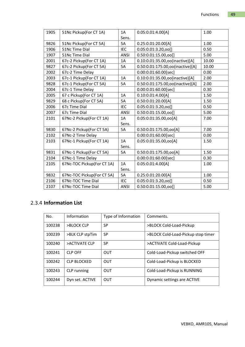
VEBKO, AMR105, Manual
49 Functions
1905 51Nc Pickup(For CT 1A) 1A Sens.
0.05:0.01:4.00[A] 1.00
9826 51Nc Pickup(For CT 5A) 5A 0.25:0.01:20.00[A] 1.00
1906 51Nc Time Dial IEC 0.05:0.01:3.20,oo[] 0.50
1907 51Nc Time Dial ANSI 0.50:0.01:15.00,oo[] 5.00
2001 67c-2 Pickup(For CT 1A) 1A 0.10:0.01:35.00,oo(inactive)[A] 10.00
9827 67c-2 Pickup(For CT 5A) 5A 0.50:0.01:175.00,oo(inactive)[A] 10.00
2002 67c-2 Time Delay 0.00:0.01:60.00[sec] 0.00
2003 67c-1 Pickup(For CT 1A) 1A 0.10:0.01:35.00,oo(inactive)[A] 2.00
9828 67c-1 Pickup(For CT 5A) 5A 0.50:0.01:175.00,oo(inactive)[A] 2.00
2004 67c-1 Time Delay 0.00:0.01:60.00[sec] 0.30
2005 67 c Pickup(For CT 1A) 1A 0.10:0.01:4.00[A] 1.50
9829 68 c Pickup(For CT 5A) 5A 0.50:0.01:20.00[A] 1.50
2006 67c Time Dial IEC 0.05:0.01:3.20,oo[] 0.50
2007 67c Time Dial ANSI 0.50:0.01:15.00,oo[] 5.00
2101 67Nc-2 Pickup(For CT 1A) 1A Sens.
0.05:0.01:35.00,oo[A] 7.00
9830 67Nc-2 Pickup(For CT 5A) 5A 0.50:0.01:175.00,oo[A] 7.00
2102 67Nc-2 Time Delay 0.00:0.01:60.00[sec] 0.00
2103 67Nc-1 Pickup(For CT 1A) 1A Sens.
0.05:0.01:35.00,oo[A] 1.50
9831 67Nc-1 Pickup(For CT 5A) 5A 0.50:0.01:175.00,oo[A] 1.50
2104 67Nc-1 Time Delay 0.00:0.01:60.00[sec] 0.30
2105 67Nc-TOC Pickup(For CT 1A) 1A Sens.
0.05:0.01:4.00[A] 1.00
9832 67Nc-TOC Pickup(For CT 5A) 5A 0.25:0.01:20.00[A] 1.00
2106 67Nc-TOC Time Dial IEC 0.05:0.01:3.20,oo[] 0.50
2107 67Nc-TOC Time Dial ANSI 0.50:0.01:15.00,oo[] 5.00
Information List
No. Information Type of Information Comments.
100238 >BLOCK CLP SP >BLOCK Cold-Load-Pickup
100239 >BLK CLP stpTim SP >BLOCK Cold-Load-Pickup stop timer
100240 >ACTIVATE CLP SP >ACTIVATE Cold-Load-Pickup
100241 CLP OFF OUT Cold-Load-Pickup switched OFF
100242 CLP BLOCKED OUT Cold-Load-Pickup is BLOCKED
100243 CLP running OUT Cold-Load-Pickup is RUNNING
100244 Dyn set. ACTIVE OUT Dynamic settings are ACTIVE

VEBKO, AMR105, Manual
50 Functions
Single-Phase Overcurrent Protection
The single-phase overcurrent protection evaluates the current that is measured by the sensitive INS-
or the normal IN input.
Applications
Plain ground fault protection at a power transformer;
Sensitive tank leakage protection.
Functional Description
The single-phase definite time overcurrent ground protection is illustrated by the tripping
characteristic as shown in Figure 2-17. The current to be measured is filtered by numerical
algorithms. Because of the high sensitivity a particularly narrow band filter is used. The current pickup
thresholds and tripping times can be set. The detected current is compared to the pickup value 50
1Ph-1 PICKUP or 50 1Ph-2 PICKUP and reported if this is violated. After expiry of the respective delay
time 50 1Ph-1 DELAY or 50 1Ph-2 DELAY, the trip command is issued. The two elements together
form a two-stage protection. The dropout value is approximately 95% of the pickup value for currents
greater than I > 0.3 · INom.
The current filter is bypassed if currents are extremely high in order to achieve a short tripping time.
This occurs automatically as soon as the instantaneous value of the current exceeds the set value of
the 50 1Ph-2 PICKUP element by at least factor 2 · √2.
Figure 2-17 Two-stage characteristic of the single-phase time-overcurrent protection
The following figure shows the logic diagram of the single-phase overcurrent protection function.

VEBKO, AMR105, Manual
51 Functions
Figure 2-18 Logic diagram of the single-phase time overcurrent protection
High-impedance Ground Fault Unit Protection
Application Examples
The high impedance protection concept is based on measuring the voltage across the paralleled CT's
to a common high-resistive resistor.
The CTs must be of the same design and feature at least a separate core for high-impedance
protection. In particular, they must have the same transformer ratios and approximately identical
knee-point voltage.With AMR105, the high-impedance principle is particularly well suited for
detecting ground faults in grounded networks at transformers, generators, motors and shunt
reactors.
Figure 2-19 shows an application example for a grounded transformer winding or a grounded
motor/generator.
The right-hand example depicts an ungrounded transformer winding or an ungrounded
motor/generator where the grounding of the system is assumed somewhere else.

VEBKO, AMR105, Manual
52 Functions
Figure 2-19 Ground fault protection according to the high-impedance principle
Function of the High-Impedance Principle
The high-impedance principle is explained on the basis of a grounded transformer winding.
No zero sequence current will flow during normal operation, i.e. the neutral point current is ISP = 0
and the phase currents are 3 I0 = IA + IB + IC = 0.
In case of an external ground fault (left in Figure 2-20), whose fault current is supplied via the
grounded neutral point, the same current flows through the transformer neutral point and the
phases. The corresponding secondary currents (all current transformers have the same
transformation ratio) compensate each other; they are connected in series. Across resistor R only a
small voltage is generated. It originates from the inner resistance of the transformers and the
connecting cables of the transformers. Even if any current transformer experiences a partial
saturation, it will become low-ohmic for the period of saturation and creates a low-ohmic shunt to
the high-ohmic resistor R. Thus, the high resistance of the resistor also has a stabilizing effect (the so-
called resistance stabilization).
Figure 2-20 Principle of ground fault protection according to the high-impedance principle

VEBKO, AMR105, Manual
53 Functions
When a ground fault occurs in the protected zone (Figure 2-20 right), there is always a neutral point
current ISP. The grounding conditions in the rest of the network determine how strong a zero
sequence current from the system is. A secondary current which is equal to the total fault current
tries to pass through the resistor R. Since the latter is high-resistive, a high voltage emerges
immediately. Therefore, the current transformers get saturated. The RMS voltage across the resistor
approximately corresponds to the knee-point voltage of the current transformers. Resistance R is
sized such that, even with the very lowest ground fault current to be detected, it generates a
secondary voltage, which is equal to half the saturation voltage of current transformers.
High-impedance Protection with AMR105
With AMR105 the sensitive measurement input INs or alternatively the insensitive measurement
input IN is used for high-impedance protection. As this is a current input, the protection detects
current through the resistor instead of the voltage across the resistor R.
Figure 2-21 illustrates the connection scheme. The protection device is connected in series to resistor
R and measures its current.
Varistor B limits the voltage when internal faults occur. High voltage peaks emerging with
transformer saturation are cut by the varistor. At the same time, voltage is smoothed without
reduction of the mean value.
Figure 2-21 Connection diagram of the ground fault differential protection according to the high-
impedance principle
For protection against overvoltages it is also important that the device is directly connected to the
grounded side of the current transformers so that the high voltage at the resistor can be kept away
from the device.
For generators, motors and shunt reactors, the high-impedance differential protection can be used
analogously. All current transformers at the overvoltage side, the undervoltage side and the current
transformer at the neutral point have to be connected in parallel when using auto-transformers.
In principle, this procedure can be applied to every protected object. When applied as busbar
protection, for example, the device is connected to the parallel connection of all feeder current
transformers via the resistor.

VEBKO, AMR105, Manual
54 Functions
Tank Leakage Protection
Application Example
The tank leakage protection has the task to detect ground leakage — even high-ohmic — between a
phase and the frame of a power transformer. The tank must be isolated from ground. A conductor
links the tank to ground, and the current through this conductor is fed to a current input of the relay.
When tank leakage occurs, a fault current (tank leakage current) will flow through the grounding
conductor to ground. This tank leakage current is detected by the single-phase overcurrent
protection as an overcurrent; an instantaneous or delayed trip command is issued in order to
disconnect all sides of the transformer.
A high-sensitivity single-phase current input is used for tank leakage protection.
Figure 2-22 Principle of tank-leakage protection
Setting Notes
General
Single-phase time overcurrent protection can be set ON or OFF at address 2701 50 1Ph.
The settings are based on the particular application. The setting ranges depend on whether the
current measuring input is a sensitive or a normal input transformer.
In case of a normal input transformer, set the pickup value for 50 1Ph-2 PICKUP in address 2702, the
pickup value for 50 1Ph-1 PICKUP in address 2705. If only one element is required, set the one not
required to ∞. In case of a sensitive input transformer, set the pickup value for 50 1Ph-2 PICKUP in
address 2703, the pickup value for 50 1Ph-1 PICKUP in address 2706. If only one element is required,
set the one not required to ∞.
If you need a tripping time delay for the 50-2 elements, set it in address 2704 50 1Ph-2 DELAY, for
the 50-1 element in address 2707 50 1Ph-1 DELAY. With setting 0 s no delay takes place.

VEBKO, AMR105, Manual
55 Functions
The selected times are additional time delays and do not include the operating time (measuring time,
etc.) of the elements. The delay can also be set to ∞; the corresponding element will then not trip
after pickup, but the pickup is reported.
Special notes are given in the following for the use as high-impedance unit protection and tank
leakage protection.
Application as High-impedance Protection
The application as high-impedance protection requires that neutral point current detection is
possible in the system in addition to phase current detection (see example in Figure 2-21).
Furthermore, a sensitive input transformer must be available at device input IN/INS. In this case, only
the pickup value for single-phase overcurrent protection is set at the AMR105 device for the current
at input IN/INS.
The entire function of high-impedance protection is, however, dependent on the interaction of
current transformer characteristics, external resistor R and voltage across R. The following section
gives information on this topic.
Current Transformer Data for High-impedance Protection
All current transformers must have an identical transformation ratio and nearly equal knee-point
voltage. This is usually the case if they are of equal design and identical rated data. The knee-point
voltage can be approximately calculated from the rated data of a CT as follows:
VKPV Knee-point voltage
RI Internal burden of the CT
PNom Nominal power of the CT
INom Secondary nominal current of CT
ALF Rated accuracy limit factor of the CT
The nominal current, nominal power and accuracy limit factor are normally stated on the rating plate
of thecurrent transformer, e.g.
Current transformer 800/5; 5P10; 30 VA
That means
INom = 5 A (from 800/5)
ALF = 10 (from 5P10)
PNom = 30 VA
The internal burden is often stated in the test report of the current transformer. If not, it can be
derived from a DC measurement on the secondary winding.

VEBKO, AMR105, Manual
56 Functions
Calculation Example:
CT 800/5; 5P10; 30 VA with Ri = 0.3 Ω
or
CT 800/1; 5P10; 30 VA with Ri = 5 Ω
Besides the CT data, the resistance of the longest connection lead between the CTs and the AMR105
device must be known.
Stability with High-impedance Protection
The stability condition is based on the following simplified assumption: If there is an external fault,
one of the current transformers gets totally saturated. The other ones will continue transmitting their
(partial) currents. In theory, this is the most unfavorable case. Since, in practice, it is also the
saturated transformer which supplies current, an automatic safety margin is guaranteed.
Figure 2-23 shows a simplified equivalent circuit. CT1 and CT2 are assumed as ideal transformers with
their inner resistances R i1 and R i2. Ra are the resistances of the connecting cables between current
transformers and resistor R. They are multiplied by 2 as they have a forward and a return line. Ra2 is
the resistance of the longest connecting cable.
CT1 transmits current I1. CT2 shall be saturated. Because of saturation the transformer represents a
low-resistance shunt which is illustrated by a dashed short-circuit line.
R >> (2Ra2 + Ri2) is a further prerequisite.
Figure 2-23 Simplified equivalent circuit of a circulating current system for high-impedance
protection
The voltage across R is then
VR = I1 · ( 2Ra2 + Ri2 )
It is assumed that the pickup value of the AMR105 corresponds to half the knee-point voltage of the
current transformers. In the balanced case results

VEBKO, AMR105, Manual
57 Functions
VR = VKPV / 2
This results in a stability limit ISL , i.e. the maximum through-fault current below which the scheme
remains stable:
Calculation Example:
For the 5 A CT as above with VKPV = 75 Vand Ri= 0.3 Ω
longest CT connection lead 22 m (24.06 yd) with 4 mm2 cross-section; this corresponds to Ra = 0.1 Ω
that is 15 × rated current or 12 kA primary.
For the 1 A CT as above with VKPV = 350 V and Ri= 5 Ω
longest CT connection lead 107 m (117.02 yd) with 2.5 mm2 cross-section, results in Ra = 0.75 Ω
that is 27 × rated current or 21.6 kA primary.
Sensitivity with High-impedance Protection
The voltage present at the CT set is forwarded to the protective relay across a series resistor R as
proportional current for evaluation. The following considerations are relevant for dimensioning the
resistor:
As already mentioned, it is desired that the high-impedance protection should pick up at half the
knee-point voltage of the CT's. The resistor R can calculated on this basis.
Since the device measures the current flowing through the resistor, resistor and measuring input of
the device must be connected in series. Since, furthermore, the resistance shall be high-resistance
(condition: R >> 2Ra2 + Ri2, as mentioned above), the inherent resistance of the measuring input can
be neglected. The resistance is then calculated from the pickup current Ipu and half the knee-point
voltage:
Calculation Example:
For the 5 A CT as above
desired pickup value Ipu = 0.1 A (equivalent to 16 A primary)

VEBKO, AMR105, Manual
58 Functions
For the 1 A CT as above
desired pickup value Ipu = 0.05 A (equivalent to 40 A primary)
Series resistor R must be rated for a minimum permanent load Ppermanent:
Furthermore, series resistor R must be rated for a fault current applying for approx. 0.5 s. This time
is usually sufficient for the backup protection to clear the fault.
The thermal load of the series resistor depends on the voltage Vrms,stab applying during an internal
fault. It is calculated according to the following formulas:
where Ik,max,int corresponds to the maximum fault current during an internal fault.
For the 5 A current transformer 800/5 with 40 kA primary, Ik,max,int equals 250 A secondary.
For the 1 A current transformer 800/1 with 40 kA primary, Ik,max,int equals 50 A secondary.
This yields a short-time load over 0.5 s for the series resistor of:
Please bear in mind that when choosing a higher pickup value Ipu, the resistance must be decreased
and, in doing so, power loss will increase significantly.
The varistor B (see following figure) must be dimensioned such that it remains high-resistive until
reaching knee-point voltage, e.g.
approx. 100 V for 5 A CT,
approx. 500 V for 1 A CT.
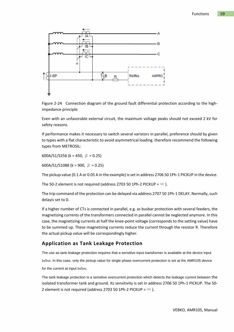
VEBKO, AMR105, Manual
59 Functions
Figure 2-24 Connection diagram of the ground fault differential protection according to the high-
impedance principle
Even with an unfavorable external circuit, the maximum voltage peaks should not exceed 2 kV for
safety reasons.
If performance makes it necessary to switch several varistors in parallel, preference should by given
to types with a flat characteristic to avoid asymmetrical loading. therefore recommend the following
types from METROSIL:
600A/S1/S256 (k = 450, β = 0.25)
600A/S1/S1088 (k = 900, β = 0.25)
The pickup value (0.1 A or 0.05 A in the example) is set in address 2706 50 1Ph-1 PICKUP in the device.
The 50-2 element is not required (address 2703 50 1Ph-2 PICKUP = ∞ ).
The trip command of the protection can be delayed via address 2707 50 1Ph-1 DELAY. Normally, such
delayis set to 0.
If a higher number of CTs is connected in parallel, e.g. as busbar protection with several feeders, the
magnetizing currents of the transformers connected in parallel cannot be neglected anymore. In this
case, the magnetizing currents at half the knee-point voltage (corresponds to the setting value) have
to be summed up. These magnetizing currents reduce the current through the resistor R. Therefore
the actual pickup value will be correspondingly higher.
Application as Tank Leakage Protection
The use as tank leakage protection requires that a sensitive input transformer is available at the device input
IN/INS. In this case, only the pickup value for single phase overcurrent protection is set at the AMR105 device
for the current at input IN/INS.
The tank leakage protection is a sensitive overcurrent protection which detects the leakage current between the
isolated transformer tank and ground. Its sensitivity is set in address 2706 50 1Ph-1 PICKUP. The 50-
2 element is not required (address 2703 50 1Ph-2 PICKUP = ∞ ).
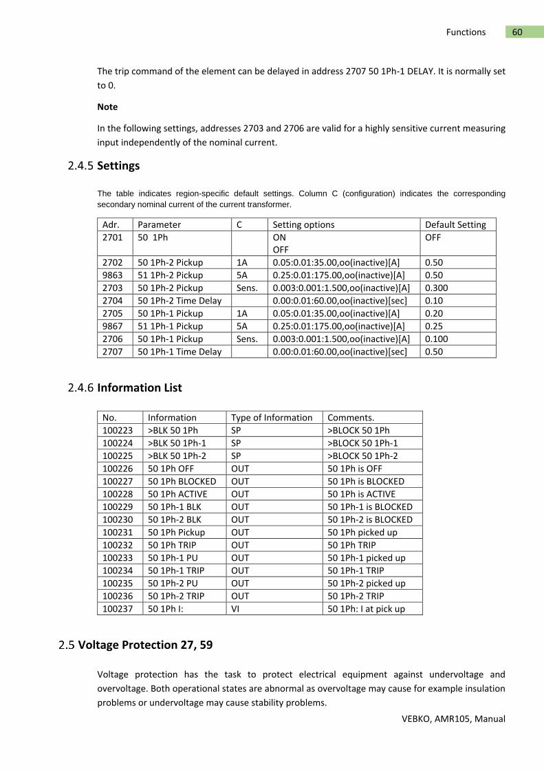
VEBKO, AMR105, Manual
60 Functions
The trip command of the element can be delayed in address 2707 50 1Ph-1 DELAY. It is normally set
to 0.
Note
In the following settings, addresses 2703 and 2706 are valid for a highly sensitive current measuring
input independently of the nominal current.
Settings
The table indicates region-specific default settings. Column C (configuration) indicates the corresponding
secondary nominal current of the current transformer.
Adr. Parameter C Setting options Default Setting
2701 50 1Ph ON OFF
OFF
2702 50 1Ph-2 Pickup 1A 0.05:0.01:35.00,oo(inactive)[A] 0.50
9863 51 1Ph-2 Pickup 5A 0.25:0.01:175.00,oo(inactive)[A] 0.50
2703 50 1Ph-2 Pickup Sens. 0.003:0.001:1.500,oo(inactive)[A] 0.300
2704 50 1Ph-2 Time Delay 0.00:0.01:60.00,oo(inactive)[sec] 0.10
2705 50 1Ph-1 Pickup 1A 0.05:0.01:35.00,oo(inactive)[A] 0.20
9867 51 1Ph-1 Pickup 5A 0.25:0.01:175.00,oo(inactive)[A] 0.25
2706 50 1Ph-1 Pickup Sens. 0.003:0.001:1.500,oo(inactive)[A] 0.100
2707 50 1Ph-1 Time Delay 0.00:0.01:60.00,oo(inactive)[sec] 0.50
Information List
No. Information Type of Information Comments.
100223 >BLK 50 1Ph SP >BLOCK 50 1Ph
100224 >BLK 50 1Ph-1 SP >BLOCK 50 1Ph-1
100225 >BLK 50 1Ph-2 SP >BLOCK 50 1Ph-2
100226 50 1Ph OFF OUT 50 1Ph is OFF
100227 50 1Ph BLOCKED OUT 50 1Ph is BLOCKED
100228 50 1Ph ACTIVE OUT 50 1Ph is ACTIVE
100229 50 1Ph-1 BLK OUT 50 1Ph-1 is BLOCKED
100230 50 1Ph-2 BLK OUT 50 1Ph-2 is BLOCKED
100231 50 1Ph Pickup OUT 50 1Ph picked up
100232 50 1Ph TRIP OUT 50 1Ph TRIP
100233 50 1Ph-1 PU OUT 50 1Ph-1 picked up
100234 50 1Ph-1 TRIP OUT 50 1Ph-1 TRIP
100235 50 1Ph-2 PU OUT 50 1Ph-2 picked up
100236 50 1Ph-2 TRIP OUT 50 1Ph-2 TRIP
100237 50 1Ph I: VI 50 1Ph: I at pick up
Voltage Protection 27, 59
Voltage protection has the task to protect electrical equipment against undervoltage and
overvoltage. Both operational states are abnormal as overvoltage may cause for example insulation
problems or undervoltage may cause stability problems.

VEBKO, AMR105, Manual
61 Functions
There are two elements each available for overvoltage protection and undervoltage protection.
Applications
Abnormally high voltages often occur e.g. in low loaded, long distance transmission lines, in
islanded systems when generator voltage regulation fails, or after full load rejection of a
generator from the system.
The undervoltage protection function detects voltage collapses on transmission lines and
electrical machines and prevents inadmissible operating states and a possible loss of stability.
Measurement Principle
Connection/Measured Values
The voltages supplied to the device can be the three phase-to-ground voltagesVA-N, VB-N, VC-N or
two phaseto- phase voltages (VA-B, VB-C) and the displacement voltage (ground voltage VN) or, in
case of a single-phase connection, any phase-to-ground voltage or phase-to-phase voltage. The
device AMR105 provide the option to detect three phase-to-ground voltages and additionally the
ground voltage. With a multiple-phase connection, the connection type was specified during
configuration of parameter 213 VT Connect. 3ph.
If there is only one voltage transformer, the device has to be informed of this fact during
configuration via address 240 VT Connect. 1ph .
The following table indicates which voltages can be evaluated by the function. The settings for this
are carried out in the P.System Data 1. Furthermore, it is indicated to which value the threshold must
be set. All voltages are fundamental frequency values.
Table 2-6 Voltage protection, selectable voltages

VEBKO, AMR105, Manual
62 Functions
Current Criterion
Depending on the system, the primary voltage transformers are arranged either on the supply side
or the load side of the associated circuit breaker. These different arrangements lead to different
behaviour of the voltage protection function when a fault occurs. When a tripping command is issued
and a circuit breaker is opened, full voltage remains on the supply side while the load side voltage
becomes zero. When voltage supply is suppressed, undervoltage protection, for instance, will remain
picked up. If pickup is to drop out, the current can be used as an additional criterion for pickup of
undervoltage protection (current supervision CS). Undervoltage pickup can only be maintained when
the undervoltage criterion satisfied and a settable minimum current level (BkrClosed I MIN) are
exceeded. Here, the largest of the three phase currents is used. When the current decreases below
the minimum current setting after the circuit breaker has opened, undervoltage protection drops
out.
Note
If parameter CURRENT SUPERV. is set to disabled in address 5120, the device picks up immediately
without measurement voltage and the undervoltage protection function in pickup. Apply measuring
voltage or block the voltage protection to continue with configuration. Moreover you have the option
of setting a flag via device operation for blocking the voltage protection. This initiates the reset of
the pickup and device configuration can be resumed.
Overvoltage Protection 59
Function
The overvoltage protection has two elements. In case of a high overvoltage, tripping switch off is
performed with a short-time delay, whereas in case of less severe overvoltages, the tripping is
performed with a longer time delay. When one of the adjustable settings is exceeded, the 59 element
picks up and trips after an adjustable time delay has elapsed. The time delay is not dependent on the
magnitude of the overvoltage. The dropout ratio for the two overvoltage elements (= Vdropout value/Vpickup
value) can be set. The following figure shows the logic diagram of the overvoltage protection function.

VEBKO, AMR105, Manual
63 Functions
Figure 2-25 Logic diagram of the overvoltage protection
Undervoltage Protection 27
Function
Undervoltage protection consists of two definite time elements (27-1 PICKUP and 27-2 PICKUP).
Therefore, tripping can be time-coordinated depending on how severe voltage collapses are. Voltage
thresholds and time delays can be set individually for both elements.
The dropout ratio for the two undervoltage elements (= Vdropout value/Vpickup value) can be set.
Figure 2-26 shows a typical voltage profile during a fault for source side connection of the voltage
transformers. Because full voltage is present after the circuit breaker has been opened, current
supervision CS described above is not necessary in this case. After the voltage has dropped below the
pickup setting, tripping is initiated after time delay 27-1 DELAY. As long as the voltage remains below
the dropout setting, reclosing is blocked.
Only after the fault has been cleared, i.e. when the voltage increases above the dropout level, the
element drops out and allows reclosing of the circuit breaker.

VEBKO, AMR105, Manual
64 Functions
Figure 2-26 Typical fault profile for source side connection of the voltage transformer (without
current supervision)
Figure 2-27 shows a fault profile for a load side connection of the voltage transformers. When the
circuit breaker is open, the voltage disappears (the voltage remains below the pickup setting), and
current supervision is used to ensure that pickup drops out after the circuit breaker has opened
(BkrClosed I MIN). After the voltage has dropped below the pickup setting, tripping is initiated after
time delay 27-1 DELAY. When the circuit breaker opens, voltage decreases to zero and undervoltage
pickup is maintained. The current value also decreases to zero so that current criterion is reset as
soon as the release threshold (BkrClosed I MIN) is exceeded. Pickup of the protection function is also
reset by the action of the AND-combination of voltage and current. As a consequence, energization
is admitted anew when the minimum command time elapsed.
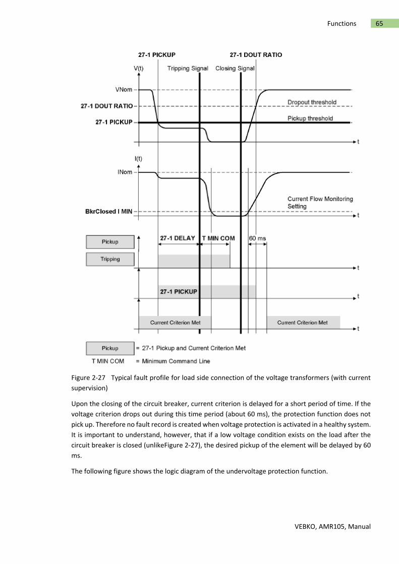
VEBKO, AMR105, Manual
65 Functions
Figure 2-27 Typical fault profile for load side connection of the voltage transformers (with current
supervision)
Upon the closing of the circuit breaker, current criterion is delayed for a short period of time. If the
voltage criterion drops out during this time period (about 60 ms), the protection function does not
pick up. Therefore no fault record is created when voltage protection is activated in a healthy system.
It is important to understand, however, that if a low voltage condition exists on the load after the
circuit breaker is closed (unlikeFigure 2-27), the desired pickup of the element will be delayed by 60
ms.
The following figure shows the logic diagram of the undervoltage protection function.
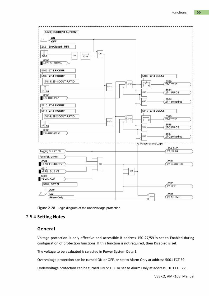
VEBKO, AMR105, Manual
66 Functions
Figure 2-28 Logic diagram of the undervoltage protection
Setting Notes
General
Voltage protection is only effective and accessible if address 150 27/59 is set to Enabled during
configuration of protection functions. If this function is not required, then Disabled is set.
The voltage to be evaluated is selected in Power System Data 1.
Overvoltage protection can be turned ON or OFF, or set to Alarm Only at address 5001 FCT 59.
Undervoltage protection can be turned ON or OFF or set to Alarm Only at address 5101 FCT 27.

VEBKO, AMR105, Manual
67 Functions
With the protection function ON, tripping, the clearing of a fault and fault recording are initiated
when the thresholds are exceeded and the set time delays have expired.
With setting Alarm Only no trip command is given, no fault is recorded and no immediate fault
annunciation is shown on the display.
Overvoltage Protection with Phase-to-phase or Phase-to-ground
Voltages
The largest of the applied voltages is evaluated for the phase-to-phase or phase-to-ground
overvoltage protection. The threshold values are set in the value to be evaluated.
The overvoltage protection has two elements. The pickup value of the lower threshold (address 5002
or 5003, 59-1 PICKUP, depending on the phase-to-ground or the phase-to-phase voltages, can be
assigned a longer time delay (address 5004, 59-1 DELAY) and the upper threshold element (address
5005 or 5006, 59-2 PICKUP) a shorter (address 5007, 59-2 DELAY) time delay. There are no specific
procedures on how the pickup values are set. However, as the function is mainly used to prevent
high insulation damage to system components and users, the threshold value 5002 , 5003 59-1
PICKUP lies generally between 110 % and 115 % of the nominal voltage and setting value 5005 , 5006
59-2 PICKUP at approximately 130 %.
The time delays of the overvoltage elements are entered at addresses 5004 59-1 DELAY and 5007 59-
2 DELAY, and should be selected in such manner that they make allowance for brief voltage peaks
that are generated during switching operations and also enable clearance of stationary overvoltages
in due time.
The choice between phase-to-ground and phase-to-phase voltage allows voltage asymmetries (e.g.
caused by a ground fault) to be taken into account (phase-to-ground) or to remain unconsidered
(phase-to-phase) during evaluation.
Note
During configuration of a single-phase voltage transformer connection (parameter 240 VT Connect.
1ph not equal to NO), parameters 213 VT Connect. 3ph and 614 OP. QUANTITY 59 are not evaluated.
In this case, exclusively parameters 5003 59-1 PICKUP or 5006 59-2 PICKUP are relevant for the
threshold values of the overvoltage protection.
Overvoltage Protection - Positive Sequence System V1
In a three-phase voltage transformer connection the positive sequence system can be evaluated for
the overvoltage protection by means of configuring parameter 614 OP. QUANTITY 59 to V1. In this
case, the threshold values of the overvoltage protection must be set in parameters 5019 59-1 PICKUP
V1 or 5020 59-2 PICKUP V1.
Overvoltage Protection - Negative Sequence System V2
In a three-phase transformer connection, parameter 614 OP. QUANTITY 59 can determine that the
negative sequence system V2 can be evaluated as a measured value for the overvoltage protection.
The negative sequence system detects voltage unbalance and can be used for the stabilization of the
time overcurrent protection. In backup protection of transformers or generators, the fault currents

VEBKO, AMR105, Manual
68 Functions
lie, in some cases, only slightly above the load currents. In order to obtain a pickup threshold of the
time overcurrent protection that is as sensitive as possible, its stabilization via the voltage protection
is necessary to avoid false tripping.
Overvoltage protection comprises two elements. Thus, with configuration of the negative system, a
longer time delay (address 5004, 59-1 DELAY) may be assigned to the lower element (address 5015,
59-1-V2 PICKUP and a shorter time delay (address 5007, 59-2 DELAY) may be assigned to the upper
element (address 5016, 59-2-V2 PICKUP). There are not clear cut procedures on how to set the pickup
values 59-1-V2 PICKUP or 59-2-V2 PICKUP as they depend on the respective station configuration.
The time delays of the overvoltage elements are entered at addresses 5004 59-1 DELAY and 5007 59-
2 DELAY, and should be selected in such manner that they make allowance for brief voltage peaks
that are generated during switching operations and also enable clearance of stationary overvoltages
in due time.
Dropout Threshold of the Overvoltage Protection
The dropout thresholds of the 59-1 element and the 59-2 element can be configured via the dropout
ratio r = VDropout/VPickup at addresses 5017 59-1 DOUT RATIO or 5018 59-2 DOUT RATIO. The
following marginal condition applies to r:
r · (configured pickup threshold) ≤ 150 V with connection of phase-to-phase voltages and phase-to-
ground voltages or
r · (configured pickup threshold) ≤ 260 V with calculation of the measured values from the connected
voltages(e.g. phase-to-phase voltages calculated from the connected phase-to-ground voltages).
The minimum hysteresis is 0.6 V.
Undervoltage Protection - Positive Sequence System V1
The positive sequence component (V1) can be evaluated for the undervoltage protection. Especially
in case of stability problems, their acquisition is advantageous because the positive sequence system
is relevant for the limit of the stable energy transmission. Concerning the pickup values there are no
specific notes on how to set them. However, because the undervoltage protection function is
primarily intended to protect induction machines from voltage dips and to prevent stability
problems, the pickup values will usually be between 60 % and 85 % of the nominal voltage.
The threshold value is multiplied as positive sequence voltage and set to √3, thus realizing the
reference to the nominal voltage.
Undervoltage protection comprises two elements. The pickup value of the lower threshold is set at
address 5110 or 5111, 27-2 PICKUP (depending on the voltage transformer connection, phase-to-
ground or phaseto- phase), while time delay is set at address 5112, 27-2 DELAY (short time delay).
The pickup value of the upper element is set at address 5102 or 5103, 27-1 PICKUP, while the time
delay is set at address 5106, 27-1 DELAY (a somewhat longer time delay). Setting these elements in
this way allows the undervoltage protection function to closely follow the stability behavior of the
system. The time settings should be selected such that tripping occurs in response to voltage dips
that lead to unstable operating conditions. On the other hand, the time delay should be long enough
to avoid tripping on short-term voltage dips.
VEBKO, AMR105, Manual
69 Functions
Undervoltage Protection with Phase-to-phase or Phase-to-ground
Voltages
In parameter 615 OP. QUANTITY 27 you can determine for undervoltage protection in a three-phase
connection that instead of the positive-sequence system V1, the smallest of the phase-to-phase
voltages Vphph or the smallest phase-to-ground voltage Vph-n is configured as a measured quantity.
The threshold values are set in the quantity to be evaluated.
Undervoltage protection comprises two elements. The pickup value of the lower threshold is set at
address 5110 or 5111, 27-2 PICKUP (depending on the voltage transformer connection, phase-to-
ground or phaseto- phase), while time delay is set at address 5112, 27-2 DELAY (short time delay).
The pickup value of the upper element is set at address 5102 or 5103, 27-1 PICKUP, while the time
delay is set at address 5106, 27-1 DELAY (a somewhat longer time delay). Setting these elements in
this way allows the undervoltage protection function to closely follow the stability behavior of the
system.
The time settings should be selected such that tripping occurs in response to voltage dips that lead
to unstable operating conditions. On the other hand, the time delay should be long enough to avoid
tripping on short-term voltage dips.
Note
During configuration of a single-phase voltage transformer connection (parameter 240 VT Connect.
1ph not equal to NO), parameters 213 VT Connect. 3ph and 615 OP. QUANTITY 27 are not evaluated.
In this case, exclusively parameters 5103 27-1 PICKUP or 5111 27-2 PICKUP are relevant for the
threshold values of the undervoltage protection.
Dropout Threshold of the Undervoltage Protection
The dropout thresholds of the 59-1 element and the 59-2 element can be parameterized via the
dropout ratio r = Vdropout/Vpickup (5113 27-1 DOUT RATIO or 5114 27-2 DOUT RATIO). The
following marginal condition applies to r:
r · (configured pickup threshold) ≤ 120 V with connection of phase-to-phase voltages and phase-to-
ground voltages)
or
r· (configured pickup threshold) ≤ 210 V with calculation of the measured values from the connected
voltages (e.g. calculated phase-to-phase voltages from the connected phase-to-ground voltages).
The minimum hysteresis is 0.6 V.
Note
If a setting is selected such that the dropout threshold (= pickup threshold · dropout ratio) results in
a greater value than 120 V/210 V, it will be limited automatically. No error message occurs.
Current Criterion for Undervoltage Protection

VEBKO, AMR105, Manual
70 Functions
The 27-1 element and the 27-2 element can be supervised by the current flow monitoring setting. If
the CURRENT SUPERV. is switched ON at address 5120 (factory setting), the release condition of the
current criterion must be fulfilled in addition to the corresponding undervoltage condition, which
means that a configured minimum current (BkrClosed I MIN, address 212) must be present to make
sure that this protective function can pick up. Thus it can be achieved that pickup of the undervoltage
protection drops out when the line is disconnected from voltage supply. Furthermore, this feature
prevents an immediate general pickup of the device when the device is powered-up without
measurement voltage being present.
Note
If parameter CURRENT SUPERV. is set to disabled at address 5120, the device picks up immediately
if the measuring-circuit voltage fails and the undervoltage protection is enabled. Furthermore,
configuration can be performed by pickup of measuring-circuit voltage or blocking of the voltage
protection.
Please note that pickup threshold BkrClosed I MIN is used in other protective functions as well,
including overload protection, restart inhibit for motors, dynamic cold load pickup and circuit breaker
maintenance.
Settings
Adr. Parameter C Setting options Default Setting
5101 27 Undervoltage Prot. ON OFF Alarm Only
OFF
5001 59 Overvoltage Prot. ON OFF Alarm Only
OFF
5102 27-1 Pickup 10:1:210[V] 75
5103 27-1 Pickup 10:1:120[V] 75
5106 27-1 Time Delay 0.00:0.01:100.00,oo[sec] 1.50
5110 27-2 Pickup 10:1:210[V] 70
5111 27-2 Pickup 10:1:120[V] 70
5112 27-2 Time Delay 0.00:0.01:100.00,oo[sec] 0.50
5113 27-1 Dropout Ratio 1.01:0.01:3.00[] 1.20
5114 27-2 Dropout Ratio 1.01:0.01:3.00[] 1.20
5120 Current Supervision ON OFF
ON
5002 59-1 Pickup 40:1:260[V] 110
5003 59-1 Pickup 40:1:150[V] 110
5004 59-1 Time Delay 0.00:0.01:100.00,oo[sec] 0.50
5005 59-2 Pickup 40:1:260[V] 120
5006 59-2 Pickup 40:1:150[V] 120
5007 59-2 Time Delay 0.00:0.01:100.00,oo[sec] 0.50
5015 59-1 Pickup Overvoltage (Neg. Seq.) 2:1:150[V] 30
5016 59-2 Pickup Overvoltage (Neg. Seq.) 2:1:150[V] 50
5017 59-1 Dropout Ratio 0.90:0.01:0.99[] 0.95
5018 59-2 Dropout Ratio 0.90:0.01:0.99[] 0.95
5019 59-1 Pickup V1 40:1:150[V] 110
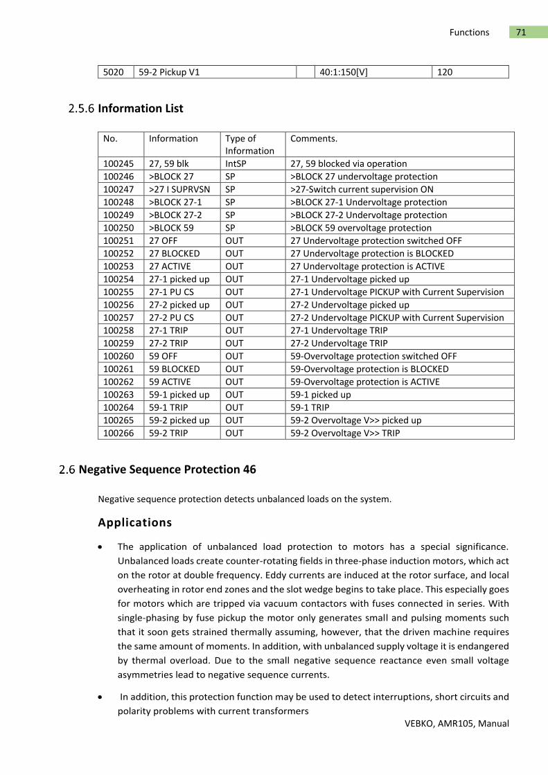
VEBKO, AMR105, Manual
71 Functions
5020 59-2 Pickup V1 40:1:150[V] 120
Information List
No. Information Type of Information
Comments.
100245 27, 59 blk IntSP 27, 59 blocked via operation
100246 >BLOCK 27 SP >BLOCK 27 undervoltage protection
100247 >27 I SUPRVSN SP >27-Switch current supervision ON
100248 >BLOCK 27-1 SP >BLOCK 27-1 Undervoltage protection
100249 >BLOCK 27-2 SP >BLOCK 27-2 Undervoltage protection
100250 >BLOCK 59 SP >BLOCK 59 overvoltage protection
100251 27 OFF OUT 27 Undervoltage protection switched OFF
100252 27 BLOCKED OUT 27 Undervoltage protection is BLOCKED
100253 27 ACTIVE OUT 27 Undervoltage protection is ACTIVE
100254 27-1 picked up OUT 27-1 Undervoltage picked up
100255 27-1 PU CS OUT 27-1 Undervoltage PICKUP with Current Supervision
100256 27-2 picked up OUT 27-2 Undervoltage picked up
100257 27-2 PU CS OUT 27-2 Undervoltage PICKUP with Current Supervision
100258 27-1 TRIP OUT 27-1 Undervoltage TRIP
100259 27-2 TRIP OUT 27-2 Undervoltage TRIP
100260 59 OFF OUT 59-Overvoltage protection switched OFF
100261 59 BLOCKED OUT 59-Overvoltage protection is BLOCKED
100262 59 ACTIVE OUT 59-Overvoltage protection is ACTIVE
100263 59-1 picked up OUT 59-1 picked up
100264 59-1 TRIP OUT 59-1 TRIP
100265 59-2 picked up OUT 59-2 Overvoltage V>> picked up
100266 59-2 TRIP OUT 59-2 Overvoltage V>> TRIP
Negative Sequence Protection 46
Negative sequence protection detects unbalanced loads on the system.
Applications
The application of unbalanced load protection to motors has a special significance.
Unbalanced loads create counter-rotating fields in three-phase induction motors, which act
on the rotor at double frequency. Eddy currents are induced at the rotor surface, and local
overheating in rotor end zones and the slot wedge begins to take place. This especially goes
for motors which are tripped via vacuum contactors with fuses connected in series. With
single-phasing by fuse pickup the motor only generates small and pulsing moments such
that it soon gets strained thermally assuming, however, that the driven machine requires
the same amount of moments. In addition, with unbalanced supply voltage it is endangered
by thermal overload. Due to the small negative sequence reactance even small voltage
asymmetries lead to negative sequence currents.
In addition, this protection function may be used to detect interruptions, short circuits and
polarity problems with current transformers
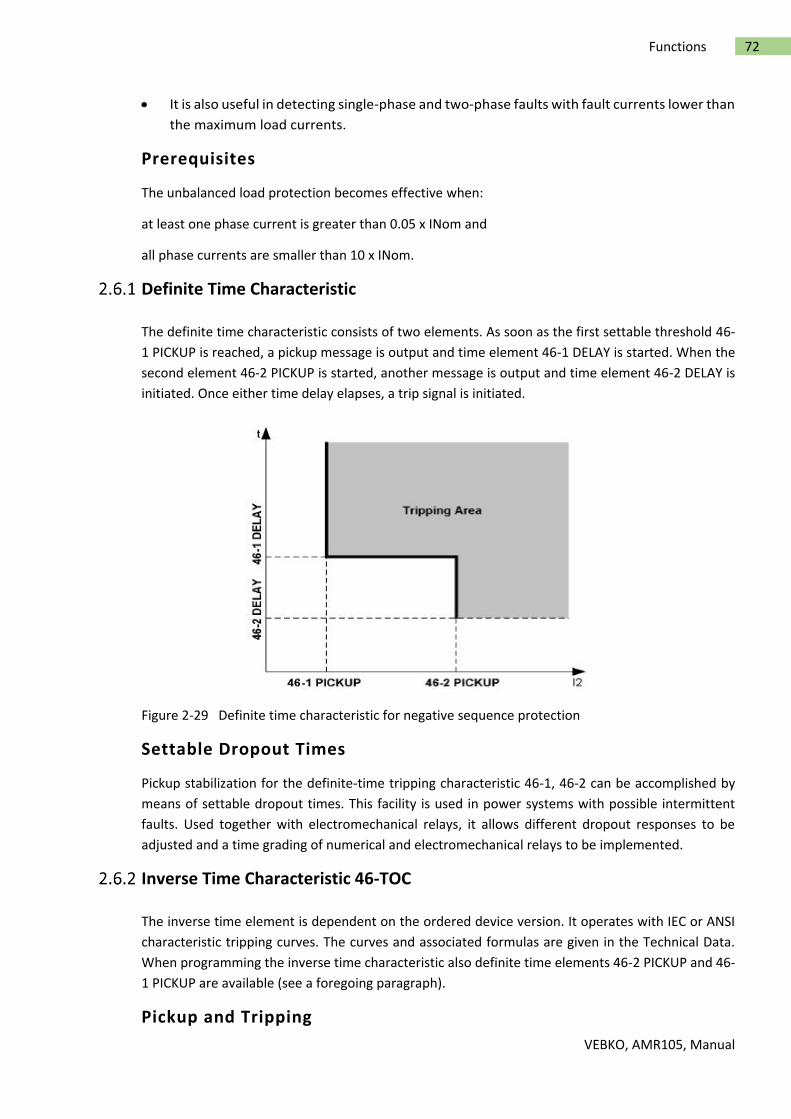
VEBKO, AMR105, Manual
72 Functions
It is also useful in detecting single-phase and two-phase faults with fault currents lower than
the maximum load currents.
Prerequisites
The unbalanced load protection becomes effective when:
at least one phase current is greater than 0.05 x INom and
all phase currents are smaller than 10 x INom.
Definite Time Characteristic
The definite time characteristic consists of two elements. As soon as the first settable threshold 46-
1 PICKUP is reached, a pickup message is output and time element 46-1 DELAY is started. When the
second element 46-2 PICKUP is started, another message is output and time element 46-2 DELAY is
initiated. Once either time delay elapses, a trip signal is initiated.
Figure 2-29 Definite time characteristic for negative sequence protection
Settable Dropout Times
Pickup stabilization for the definite-time tripping characteristic 46-1, 46-2 can be accomplished by
means of settable dropout times. This facility is used in power systems with possible intermittent
faults. Used together with electromechanical relays, it allows different dropout responses to be
adjusted and a time grading of numerical and electromechanical relays to be implemented.
Inverse Time Characteristic 46-TOC
The inverse time element is dependent on the ordered device version. It operates with IEC or ANSI
characteristic tripping curves. The curves and associated formulas are given in the Technical Data.
When programming the inverse time characteristic also definite time elements 46-2 PICKUP and 46-
1 PICKUP are available (see a foregoing paragraph).
Pickup and Tripping
VEBKO, AMR105, Manual
73 Functions
The negative sequence current I2 is compared to the setting value 46-TOC PICKUP. When the
negative sequence current exceeds 1.1 times the setting value, a pickup annunciation is generated.
The tripping time is calculated from the negative sequence current according to the characteristic
selected. When tripping time is reached, a tripping command is issued. The characteristic curve is
illustrated in the following Figure.
Figure 2-30 Inverse time characteristic for negative sequence protection
Dropout for IEC Curves
The element drops out when the negative sequence current decreases to approx. 95% of the pickup
setting.The time delay resets immediately to be ready for another pickup operation.
Dropout for ANSI Curves
When using an ANSI curve it can be selected whether the dropout of the element is to occur
instantaneously or whether dropout is to be performed by means of the disk emulation mechanism.
„Instantaneous“ means that the drop out will occur when a 95 % of the pickup value is reached. For
a new pickup the time counter starts at zero.
The disk emulation evokes a dropout process (timer counter is decrementing) which begins after de-
energization. This process corresponds to the reset of a Ferraris-disk (explaining its denomination
"disk emulation"). In case several faults occur in succession, the "history" is taken into consideration
due to the inertia of the Ferraris-disk, and the time response is adapted. This ensures a proper
simulation of the temperature rise of the protected object even for extremely fluctuating unbalanced
load values. Reset begins as soon as 90 % of thesetting value is reached, in accordance with the
dropout curve of the selected characteristic. In the range between the dropout value (95 % of the

VEBKO, AMR105, Manual
74 Functions
pickup value) and 90 % of the setting value, the incrementing and decrementing process is in idle
state.
Disk emulation offers advantages when the behavior of the negative sequence protection must be
coordinated with other relays in the system based on electromagnetic measuring principles.
Logic
The following figure shows the logic diagram for the negative sequence protection function. The
protection may be blocked via a binary input. This resets pickup and time elements and clears
measured values.
When the negative sequence protection criteria are no longer satisfied (i.e. all phase currents below
0.05 x INom or at least one phase current is greater than 10 x INom) all pickups issued by the negative
sequence protection function are reset.
Figure 2-31 Logic diagram of the unbalanced load protection

VEBKO, AMR105, Manual
75 Functions
The pickup of the definite time overcurrent protection can be stabilized by the configured dropout
time 4012 46 T DROP-OUT. This time is started and maintains the pickup condition if the current falls
below the threshold. Therefore, the function does not drop out at high speed. The trip command
delay time continues running. After the dropout delay time has elapsed, the pickup is reported OFF
and the trip delay time is reset unless the threshold has been exceeded again. If the threshold is
exceeded again during the dropout delay time, the time is canceled. The trip command delay time
continues running. Should the threshold value be exceeded after its expiry, the trip command is
issued immediately. If the threshold value is not exceeded at this time, there will be no reaction. If
the threshold value is exceeded again after expiry of the trip-command delay time, while the delay
time is still running, tripping occurs immediately.
The configured dropout times do not influence the tripping times of the inverse time elements as
these depend dynamically on the measured current value. For purposes of dropout coordination,
disc emulation is used with electro-mechanical relays.
Setting Notes
General
The function type has been specified during configuration of the protection functions. If only the
definite time elements are desired, the address 46 should be set to Definite Time. Selecting 46 = TOC
IEC or TOC ANSI in address 140 will additionally make all parameters available that are relevant for
the inverse time characteristics. If this function is not required, then Disabled is set.
The function can be turned ON or OFF in address 4001 FCT 46.
The default pickup settings and delay settings are generally sufficient for most applications. If data is
available from the manufacturer regarding the allowable long-term load imbalance and the allowable
load imbalance per unit of time, this data should be used preferentially. It is important to note that
the manufacturer's data relate to the primary values of the machine, for example, the maximum
permissible permanent inverse current is referred to the nominal machine current. For the setting
values at the protection device, this information is converted to the secondary inverse current. The
following applies
with
I2 perm prim permissible thermal inverse current of the motor
INom Motor Nominal Motor Current
ICT sec Secondary Nominal Current of the Current Transformer
ICT prim Primary nominal current of the current transformer
Definite Time Elements
VEBKO, AMR105, Manual
76 Functions
The unbalanced load protection function comprises two elements. Therefore, the upper element
(address 4004 46-2 PICKUP) can be set to a short time delay4005 46-2 DELAY) and the lower element
(address 4002 46-1 PICKUP) can be set to a somewhat longer time delay (address 4003 46-1 DELAY).
This allows the lower element to act, e.g. as an alarm, while the upper element will cut the inverse
time characteristic as soon as high inverse currents are present. If 46-2 PICKUP is set to about 60%,
tripping is always performed with the thermal characteristic. On the other hand, with more than 60%
of unbalanced load, a two-phase fault can be assumed. The delay time 46-2 DELAY must be
coordinated with the system grading of phase-to-phase faults. If power supply with current I is
provided via just two phases, the following applies to the inverse current:
Examples:
Motor with the following data:
Nominal current INom Motor = 545 A
Continuously permissible negative sequence current I2 dd prim /INom Motor = 0.11 continuous
Briefly permissible negative sequence current I2 long-term prim /INom Motor= 0.55 for T max = 1 s
Current transformer INomprim/INomsec = 600 A/1 A
Setting value 46-1 Pickup = 0.11 · 545 A · (1/600 A) = 0.10 A
Setting value 46-2 Pickup = 0.55 · 545 A · (1/600 A) = 0.50 A
When protecting feeder or cable systems, unbalanced load protection may serve to identify low
magnitude unsymmetrical faults below the pickup values of the directional and non-directional
overcurrent elements.
Here, the following must be observed:
A phase-to-ground fault with current I corresponds to the following negative sequence current:
On the other hand, with more than 60% of unbalanced load, a phase-to-phase fault can be assumed.
The delaytime 46-2 DELAY must be coordinated with the system grading of phase-to-phase faults.
For a power transformer, unbalanced load protection may be used as sensitive protection for low
magnitude phase-to-ground and phase-to-phase faults. In particular, this application is well suited
for delta-wye transformers where low side phase-to-ground faults do not generate high side zero
sequence currents (e.g. vector group Dy).
Since transformers transform symmetrical currents according to the transformation ratio "CTR", the
relationship between negative sequence currents and total fault current for phase-to-phase faults
and phase-to-ground faults are valid for the transformer as long as the turns ratio "CTR" is taken into
consideration.

VEBKO, AMR105, Manual
77 Functions
Consider a transformer with the following data:
Base Transformer Rating SNomT = 16 MVA
Primary Nominal Voltage VNom = 110 kV
Secondary Nominal Voltage VNom = 20 kV (TRV = 110/20)
Vector Groups Dy5
High Side CT 100 A / 1 A (CTI = 100)
The following fault currents may be detected at the low side:
If 46-1 PICKUP on the high side of the devices is set to = 0.1, then a fault current of I = 3 · TRV · TRI ·
46-1PICKUP = 3 · 110/20 · 100 · 0.1 A = 165 A for single-phase faults and √3 · TRV · TRI ·46-1 PICKUP
= 95 A can be detected for two-phase faults at the low side. This corresponds to 36% and 20% of the
transformer nominal current respectively. It is important to note that load current is not taken into
account in this simplified example.
As it cannot be recognized reliably on which side the thus detected fault is located, the delay time
46-1 DELAY must be coordinated with other downstream relays in the system.
Pickup Stabilization (definite-time overcurrent protection)
Pickup of the definite time elements can be stabilized by means of a configurable dropout time. This
dropout time is set in 4012 46 T DROP-OUT.
IEC Curves (Inverse Time Tripping Curve)
The thermal behavior of a machine can be closely replicated due to negative sequence by means of
an inverse time tripping curve. In address 4006 46 IEC CURVE, select out of three IEC curves provided
by the device the curve which is most similar to the thermal unbalanced load curve provided by the
manufacturer. The tripping curves of the protective relay, and the formulas on which they are based,
are given in the Technical Data.
It must be noted that a safety factor of about 1.1 has already been included between the pickup value
and the setting value when an inverse time characteristic is selected. This means that a pickup will
only occur if an unbalanced load of about 1.1 times the setting value 46-TOC PICKUP is present
(address 4008). The dropout is performed as soon as the value falls below 95% of the pickup value.
The associated time multiplier is entered at address 4010, 46-TOC TIMEDIAL.
The time multiplier can also be set to ∞. After pickup the element will then not trip. Pickup, however,
will be signaled. If the inverse time element is not required at all, address 140 46 should be set to
Definite Time during the configuration of protection functions.
ANSI Curves (Inverse Time Tripping Curve)
Behavior of a machine due to negative sequence current can be closely replicated by means of an
inverse time tripping curve. In address 4007 the 46 ANSI CURVE, select out of four ANSI curves
provided by the device the curve which is most similar to the thermal unbalanced load curve provided
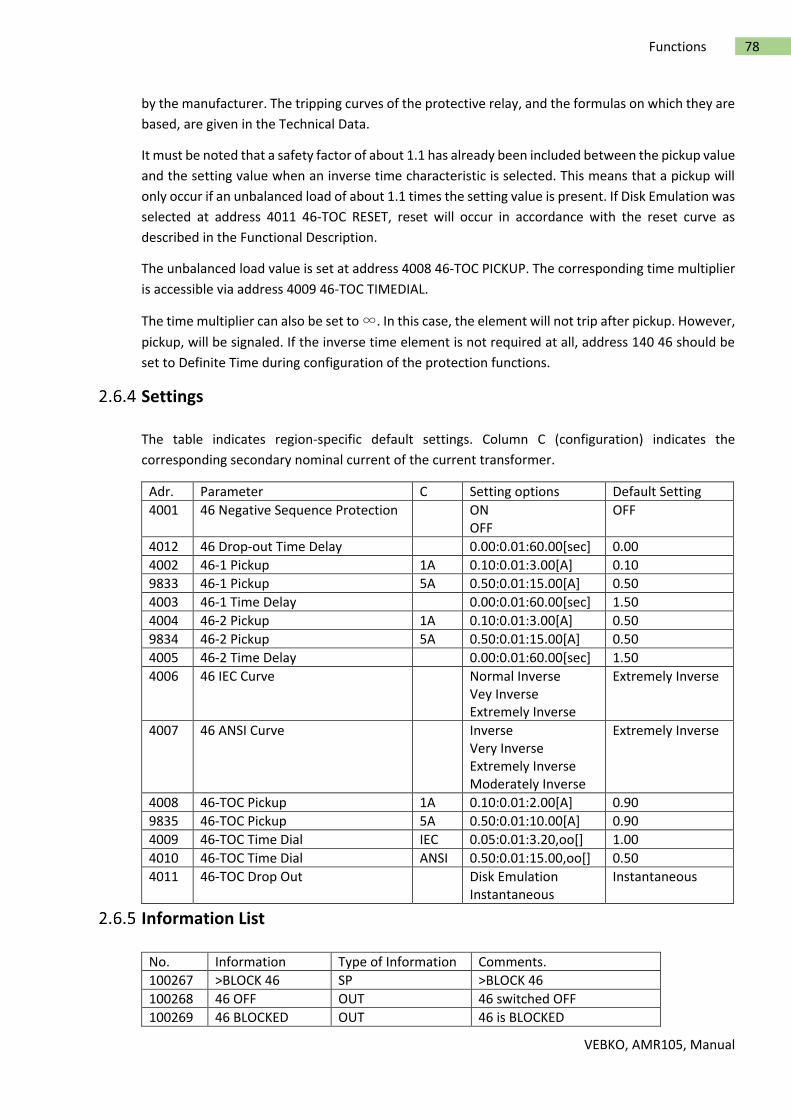
VEBKO, AMR105, Manual
78 Functions
by the manufacturer. The tripping curves of the protective relay, and the formulas on which they are
based, are given in the Technical Data.
It must be noted that a safety factor of about 1.1 has already been included between the pickup value
and the setting value when an inverse time characteristic is selected. This means that a pickup will
only occur if an unbalanced load of about 1.1 times the setting value is present. If Disk Emulation was
selected at address 4011 46-TOC RESET, reset will occur in accordance with the reset curve as
described in the Functional Description.
The unbalanced load value is set at address 4008 46-TOC PICKUP. The corresponding time multiplier
is accessible via address 4009 46-TOC TIMEDIAL.
The time multiplier can also be set to ∞. In this case, the element will not trip after pickup. However,
pickup, will be signaled. If the inverse time element is not required at all, address 140 46 should be
set to Definite Time during configuration of the protection functions.
Settings
The table indicates region-specific default settings. Column C (configuration) indicates the
corresponding secondary nominal current of the current transformer.
Adr. Parameter C Setting options Default Setting
4001 46 Negative Sequence Protection ON OFF
OFF
4012 46 Drop-out Time Delay 0.00:0.01:60.00[sec] 0.00
4002 46-1 Pickup 1A 0.10:0.01:3.00[A] 0.10
9833 46-1 Pickup 5A 0.50:0.01:15.00[A] 0.50
4003 46-1 Time Delay 0.00:0.01:60.00[sec] 1.50
4004 46-2 Pickup 1A 0.10:0.01:3.00[A] 0.50
9834 46-2 Pickup 5A 0.50:0.01:15.00[A] 0.50
4005 46-2 Time Delay 0.00:0.01:60.00[sec] 1.50
4006 46 IEC Curve Normal Inverse Vey Inverse Extremely Inverse
Extremely Inverse
4007 46 ANSI Curve Inverse Very Inverse Extremely Inverse Moderately Inverse
Extremely Inverse
4008 46-TOC Pickup 1A 0.10:0.01:2.00[A] 0.90
9835 46-TOC Pickup 5A 0.50:0.01:10.00[A] 0.90
4009 46-TOC Time Dial IEC 0.05:0.01:3.20,oo[] 1.00
4010 46-TOC Time Dial ANSI 0.50:0.01:15.00,oo[] 0.50
4011 46-TOC Drop Out Disk Emulation Instantaneous
Instantaneous
Information List
No. Information Type of Information Comments.
100267 >BLOCK 46 SP >BLOCK 46
100268 46 OFF OUT 46 switched OFF
100269 46 BLOCKED OUT 46 is BLOCKED

VEBKO, AMR105, Manual
79 Functions
100270 46 ACTIVE OUT 46 is ACTIVE
100271 46-2 picked up OUT 46-2 picked up
100272 46-1 picked up OUT 46-1 picked up
100273 46-TOC pickedup OUT 46-TOC picked up
100274 46 TRIP OUT 46 TRIP
100275 46 Dsk pickedup OUT 46 Disk emulation picked up
Frequency Protection 81 O/U
The frequency protection function detects abnormally high and low frequencies in the system or in
electrical machines. If the frequency lies outside the allowable range, appropriate actions are
initiated, such as load shedding or separating a generator from the system.
Applications
Decrease in system frequency occurs when the system experiences an increase in the real
power demand,or when a malfunction occurs with a generator governor or automatic
generation control (AGC) system. The frequency protection function is also used for
generators which (for a certain time) operate to an island network. This is due to the fact
that the reverse power protection cannot operate in case of a drive power failure. The
generator can be disconnected from the power system by means of the frequency decrease
protection.
Increase in system frequency occurs e.g. when large blocks of load (island network) are
removed from the system, or again when a malfunction occurs with a generator governor.
This entails risk of self-excitation for generators feeding long lines under no-load conditions.
Description
Detection of Frequency
The frequency is detected preferably from the positive sequence voltage. If this voltage is too low,
the phase-to-phase voltage VA-B at the device is used. If the amplitude of this voltage is too small, one
of the other phase-to-phase voltages is used instead.
Through the use of filters and repeated measurements, the frequency evaluation is free from
harmonic influencesand very accurate.
Overfrequency/Underfrequency
Frequency protection consists of four frequency elements. To make protection flexible for different
power system conditions, theses elements can be used alternatively for frequency decrease or
increase separately, and can be independently set to perform different control functions.
Operating Range
The frequency can be determined as long as in a three-phase voltage transformer connection the
positive-sequence system of the voltages, or alternatively, in a single-phase voltage transformer
connection, the respective voltage is present and of sufficient magnitude. If the measured voltage
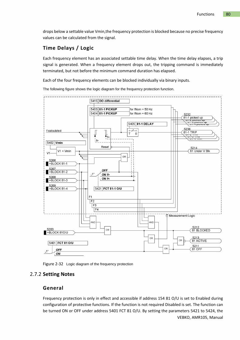
VEBKO, AMR105, Manual
80 Functions
drops below a settable value Vmin,the frequency protection is blocked because no precise frequency
values can be calculated from the signal.
Time Delays / Logic
Each frequency element has an associated settable time delay. When the time delay elapses, a trip
signal is generated. When a frequency element drops out, the tripping command is immediately
terminated, but not before the minimum command duration has elapsed.
Each of the four frequency elements can be blocked individually via binary inputs.
The following figure shows the logic diagram for the frequency protection function.
Figure 2-32 Logic diagram of the frequency protection
Setting Notes
General
Frequency protection is only in effect and accessible if address 154 81 O/U is set to Enabled during
configuration of protective functions. If the function is not required Disabled is set. The function can
be turned ON or OFF under address 5401 FCT 81 O/U. By setting the parameters 5421 to 5424, the

VEBKO, AMR105, Manual
81 Functions
function of each of the elements 81-1 PICKUP to 81-4 PICKUP is set individually as overfrequency or
underfrequency protection or set to OFF, if the element is not required.
Minimum Voltage
Address 5402 Vmin is used to set the minimum voltage. Frequency protection is blocked as soon as
the minimum voltage is undershot. On all three-phase connections and single-phase connections of
a phase-to-phase voltage, the threshold must be set as a phase-to-phase value. With a single phase-
to-ground connection the threshold must be set as a phase voltage.
Pickup Values
The setting as overfrequency or underfrequency element does not depend on the parameter
threshold values of the respective element. An element can also function, for example, as an
overfrequency element if its threshold value is set below the nominal frequency and vice versa.
If frequency protection is used for load shedding purposes, the setting values depend on the actual
power system conditions. Normally, a time coordinated load shedding is required that takes into
account the importance of the consumers or consumer groups.
Further application examples exist in the field of power stations. Here too, the frequency values to
be set mainly depend on the specifications of the power system / power station operator. The
underfrequency protection safeguards the power station's own demand by disconnecting it from the
power system on time. The turbo governor regulates the machine set to the nominal speed.
Consequently, the station's own demands can be continuously supplied at nominal frequency.
Under the assumption that the apparent power is reduced by the same degree, turbine-driven
generators can, as a rule, be continuously operated down to 95% of the nominal frequency. However,
for inductive consumers, the frequency reduction not only means an increased current input, but
also endangers stable operation. For this reason, only a short-term frequency reduction down to
about 48 Hz (for fN = 50 Hz) or 58 Hz (for fN = 60 Hz) is permissible.
A frequency increase can, for example, occur due to a load shedding or malfunction of the speed
regulation (e.g. in an island network). In this way, the frequency increase protection can, for example,
be used as overspeed protection.
Dropout Thresholds
The dropout threshold is defined via the adjustable dropout-difference address 5415 DO differential.
It can thus be adjusted to the network conditions. The dropout difference is the absolute-value
difference between pickup threshold and dropout threshold. The default value of 0.02 Hz can usually
remain. Should, however, frequent minor frequency fluctuations be expected, this value should be
increased.
Time Delays
The delay times 81-1 DELAY to 81-4 DELAY (addresses 5405, 5408, 5411 and 5414) allow the
frequency elements to be time coordinated, e.g. for load shedding equipment. The set times are
additional delay times not including the operating times (measuring time, dropout time) of the
protection function.

VEBKO, AMR105, Manual
82 Functions
Settings
Adr. Parameter C Setting options Default Setting
5401 81 Over/Under Frequency Protection ON OFF
OFF
5421 81-1 Over/Under Frequency Protection
OFF ON-Overfrequency Stage ON-Underfrequency Stage
OFF
5422 81-2 Over/Under Frequency Protection
OFF ON-Overfrequency Stage ON-Underfrequency Stage
OFF
5423 81-3 Over/Under Frequency Protection
OFF ON-Overfrequency Stage ON-Underfrequency Stage
OFF
5424 81-4 Over/Under Frequency Protection
OFF ON-Overfrequency Stage ON-Underfrequency Stage
OFF
5402 Minimum required voltage for operation
10:1:150[V] 65
5415 Dropout Differential 0.02:0.01:1.00[HZ] 0.02
5403 81-1 Pickup 50Hz 40.00:0.05:60.00[HZ] 49.50
5404 81-1 Pickup 60Hz 50.00:0.05:70.00[HZ] 59.50
5405 81-1 Time Delay 0.00:0.01:100.00,oo[sec] 60.00
5406 81-2 Pickup 50Hz 40.00:0.05:60.00[HZ] 49.00
5407 81-2 Pickup 60Hz 50.00:0.05:70.00[HZ] 59.00
5408 81-2 Time Delay 0.00:0.01:100.00,oo[sec] 30.00
5409 81-3 Pickup 50Hz 40.00:0.05:60.00[HZ] 47.50
5410 81-3 Pickup 60Hz 50.00:0.05:70.00[HZ] 57.50
5411 81-3 Time Delay 0.00:0.01:100.00,oo[sec] 3.00
5412 81-4 Pickup 50Hz 40.00:0.05:60.00[HZ] 51.00
5413 81-4 Pickup 60Hz 50.00:0.05:70.00[HZ] 61.00
5414 81-4 Time Delay 0.00:0.01:100.00,oo[sec] 30.00
Information List
No. Information Type of Information Comments.
100301 >BLOCK 81O/U SP >BLOCK 81O/U
100302 >BLOCK 81-1 SP >BLOCK 81-1
100303 >BLOCK 81-2 SP >BLOCK 81-2
100304 >BLOCK 81-3 SP >BLOCK 81-3
100305 >BLOCK 81-4 SP >BLOCK 81-4
100306 81 OFF OUT 81 OFF
100307 81 BLOCKED OUT 81 BLOCKED
100308 81 ACTIVE OUT 81 ACTIVE
100309 81 Under V Blk OUT 81 Under Voltage Block
100310 81-1 picked up OUT 81-1 picked up
100311 81-2 picked up OUT 81-2 picked up
100312 81-3 picked up OUT 81-3 picked up

VEBKO, AMR105, Manual
83 Functions
100313 81-4 picked up OUT 81-4 picked up
100314 81-1 TRIP OUT 81-1 TRIP
100315 81-2 TRIP OUT 81-2 TRIP
100316 81-3 TRIP OUT 81-3 TRIP
100317 81-4 TRIP OUT 81-4 TRIP
Monitoring Functions
The device is equipped with extensive monitoring capabilities. In addition, the measured values are
also constantly monitored for plausibility, therefore, the current transformer and voltage
transformer circuits are largely integrated into the monitoring.
Measurement Supervision
Monitoring of the Transformer Circuits
Open circuits or short circuits in the secondary circuits of the current and voltage transformers, as
well as faults in the connections (important during commissioning!), are detected and reported by
the device. The measured quantities are periodically checked in the background for this purpose, as
long as no system fault is present.
Current Symmetry
During normal system operation, symmetry among the input currents is expected. The monitoring of
the measured values in the device checks this balance. The smallest phase current is compared to
the largest phase current. Asymmetry is detected if | Imin | / | Imax | < BAL. FACTOR I as long as
Imax > BALANCE I LIMIT is valid. Thereby Imax is the largest of the three phase currents and Imin the
smallest. The symmetry factor BAL. FACTOR I (address 8105) represents the allowable asymmetry of
the phase currents while the limit value (address 8104) is the lower limit of the operating range of
this monitoring (see Figure 2-33). Both parameters can be set. The dropout ratio is about 97 %. This
fault is signalled after settable delay time with „Fail I balance“.
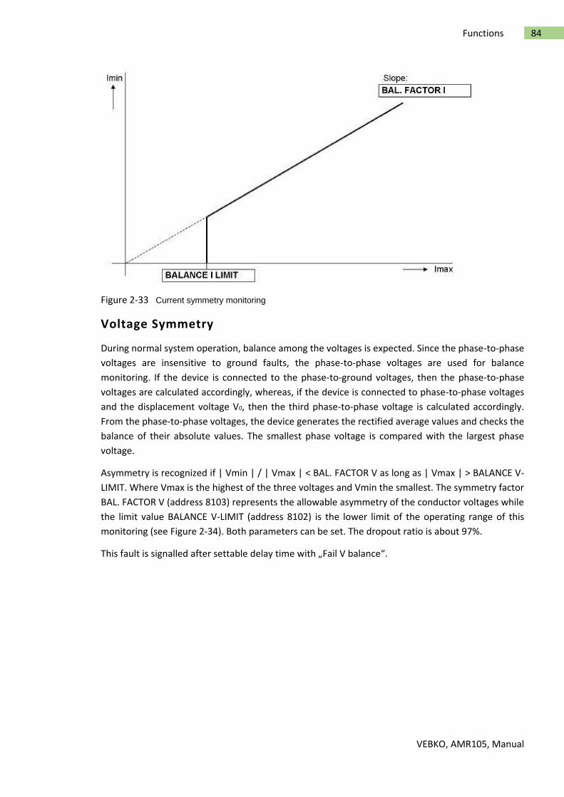
VEBKO, AMR105, Manual
84 Functions
Figure 2-33 Current symmetry monitoring
Voltage Symmetry
During normal system operation, balance among the voltages is expected. Since the phase-to-phase
voltages are insensitive to ground faults, the phase-to-phase voltages are used for balance
monitoring. If the device is connected to the phase-to-ground voltages, then the phase-to-phase
voltages are calculated accordingly, whereas, if the device is connected to phase-to-phase voltages
and the displacement voltage V0, then the third phase-to-phase voltage is calculated accordingly.
From the phase-to-phase voltages, the device generates the rectified average values and checks the
balance of their absolute values. The smallest phase voltage is compared with the largest phase
voltage.
Asymmetry is recognized if | Vmin | / | Vmax | < BAL. FACTOR V as long as | Vmax | > BALANCE V-
LIMIT. Where Vmax is the highest of the three voltages and Vmin the smallest. The symmetry factor
BAL. FACTOR V (address 8103) represents the allowable asymmetry of the conductor voltages while
the limit value BALANCE V-LIMIT (address 8102) is the lower limit of the operating range of this
monitoring (see Figure 2-34). Both parameters can be set. The dropout ratio is about 97%.
This fault is signalled after settable delay time with „Fail V balance“.

VEBKO, AMR105, Manual
85 Functions
Figure 2-34 Voltage symmetry monitoring
Phase Sequence of Voltage and Current
To detect swapped phase connections in the voltage and current input circuits, the phase sequence
of the phase-to-phase measured voltages and the phase currents are checked by monitoring the
sequence of same polarity zero crossing of the voltages.
Direction measurement with normal voltages, path selection for fault location, and negative
sequence detection all assume a phase sequence of "abc". Phase rotation of measurement quantities
is checked by verifying the phase sequences. For that purpose, the phase-sequence monitoring uses
the phase-to-phase voltages VAB, VBC, VCA.
Voltages: VAB before VBC before VCA and
Currents: IA before IB before IC.
Verification of the voltage phase rotation is done when each measured voltage is at least
|VAB|, |VBC|, |VCA| > 40 V.
Verification of the current phase rotation is done when each measured current is at least:
|IA|, |IB|, |IC| > 0.5 INom.
For abnormal phase sequences, the messages „Fail Ph. Seq. V“ or „Fail Ph. Seq. I“ are issued,
along with the switching of this message „Fail Ph. Seq.“.
For applications in which an opposite phase sequence is expected, the protective relay should be
adjusted via a binary input or the respective parameter PHASE SEQ. (address 209). If the phase
sequence is changed in the relay, phases B and C internal to the relay are reversed, and the positive
and negative sequence currents are thereby exchanged. The phase-related messages, malfunction
values, and measured values are not affected by this.

VEBKO, AMR105, Manual
86 Functions
Measurement Voltage Failure Detection
Requirements
The measurement voltage failure detection function, referred to as „Fuse Failure Monitor“ (FFM),
only operates under the following condition:
Three phase-to-ground voltages are connected; with phase-to-phase voltages and VN or
single-phase connection, the function is disabled.
Purpose of the Fuse Failure Monitor
In case of a measuring voltage failure caused by a fault or a broken wire in the voltage transformer
secondary system, a zero voltage can be simulated to individual measuring loops. The displacement
voltage element of the sensitive ground fault detection, the directional overcurrent protection, the
voltage-controlled inverse time non-directional overcurrent protection, the undervoltage protection
and the synchronization function in the AMR105 can thereby acquire incorrect measuring results.
Of course, supervision of the miniature circuit breaker and the Fuse Failure Monitor can be used at
the same time.
Mode of Operation – Grounded System
The device is informed of the application of the FFM in a grounded system via address 5301 FUSE
FAIL MON. Solid grounded.
Note
On systems where the ground fault current is very small or absent (e.g. ungrounded supply
transformers), fuse failure monitoring must be disabled or set to Coil.gnd./isol..
The logic diagram on the operating mode in a grounded system is illustrated in Figure 2-35.
Depending on the configuration and MLFB, the FFM operates with measured or calculated values VN
or IN. If zero sequence voltage occurs without a ground fault current being registered simultaneously,
then there is an asymmetrical fault in the secondary circuit of the voltage transformer. The
displacement voltage element of the sensitive ground fault detection, the directional overcurrent
protection (phase and ground function), the voltage-controlled inverse time non-directional
overcurrent protection, the undervoltage protection and the synchronization function are blocked if
parameter 5310 BLOCK PROT. is set to YES.
The FFM picks up if the ground voltage VN is higher than the set limit value under address 5302 FUSE
FAIL 3Vo and if the ground current IN lies below the set limit value under address 5303 FUSE FAIL
RESID.
Pickup occurs in accordance with the configured values. A hysteresis of 105% for the dropout is
integrated for IN or 95% for VN. In case of low-current asymmetrical faults in systems with week
infeed, the ground current caused by the fault could lie below the pickup threshold of the Fuse Failure
Monitor. Overfunctioning of the Fuse Failure Monitor can, however, cause the feeder protection
device to underfunction since all protection functions that use voltage signals are blocked. In order
to prevent overfunctioning of the FFM, the phase currents are also checked. If at least one phase

VEBKO, AMR105, Manual
87 Functions
current lies above the pickup threshold of 5303 FUSE FAIL RESID, it can be assumed that the zero
current created by a fault will equally exceed this threshold.
In order to immediately detect an existing fault after switching in, the following applies: If a ground
current IN is detected within 10 seconds after recognition of the Fuse Failure criterion, the protection
assumes a fault and removes the blocking by the Fuse Failure Monitor for the duration of the fault.
If, on the other hand, the voltage failure criterion is present for longer than approx. 10 s, the blocking
is permanently activated. After this time has elapsed, it can be assumed that a fuse failure has actually
occurred. Only 10 s after the voltage criterion has been removed by correction of the secondary
circuit failure, will the blocking automatically reset, thereby releasing the blocked protection
functions.
The generation of the internal signal „Alarm FFM“ for the operation in isolated systems is shown in
Figure 2-36.
Figure 2-35 Logic diagram of the Fuse Failure Monitor for grounded networks

VEBKO, AMR105, Manual
88 Functions
Mode of Operation – Isolated System and 3-phase Fuse Failure
The FFM can also function in isolated and compensated (grounded) systems where only low ground
currents are expected. This is indicated to the device via address 5301 FUSE FAIL MON..
The logic diagram on the functioning in an isolated system and for 3-phase fuse failure is shown in
Figure 2-36. The following is a description of the principles for 1-phase, 2-phase and 3-phase faults
in a secondary voltage transformer system. If this part of the FFM logic picks up, the internal signal
„Alarm FFM“ is generated. The processing of this signal is shown in Figure 2-35.
Figure 2-36 Logic diagram of the Fuse Failure Monitor for isolated systems
Single- and Two-phase Failures in Voltage Transformer Circuits
The measuring voltage failure detection is based on the fact that a significant negative sequence
system is formed in the voltage during single- or two-phase voltage failure, however without
influencing the current. This enables a clear distinction from asymmetries impressed by the power

VEBKO, AMR105, Manual
89 Functions
system. If the negative sequence system is related to the current positive sequence system, the
following rules apply to the Fault-free Case:
If a fault occurs in the voltage transformer secondary system, the following rules apply to the Single-
phase Failure:
If a fault occurs in the voltage transformer secondary system, the following rules apply to the Two-
phase Failure:
In case of a failure of one or two phases of the primary system, the current also shows a negative
sequence system of 0.5 or 1. Consequently, the voltage monitoring does not respond since no voltage
transformer fault can be present. In order to avoid occurrence of an overfunctioning of the measuring
voltage failure detection due to inaccuracy, the function is blocked below a minimum threshold of
the positive sequence systems of voltage (V1 < 0.1 VNom) and current (I1 < 0.1 INom).
Three-phase Failures in Voltage Transformer Circuits
A 3-phase failure in the voltage transformer secondary system cannot be detected via the positive-
and negative-sequence system as described above. The monitoring of the progress of current and
voltage over time is required here. If a voltage dip to almost zero occurs (or if the voltage is zero),
and the current remains unchanged,a 3-phase failure in the voltage transformer secondary system
can be concluded. The jump detection is used for this purpose. The sensitivity of the jump detection
for current can be increased via parameter FFM Idiff (3ph).
Broken Wire Monitoring of Voltage Transformer Circuits
Requirements
This function is only available in device version „World“ (Ordering Information Pos. 10 = B), as it is
only used in certain regions. Furthermore, the measurement of all three phase-to-ground voltages is
a requirement. If only two phase-to-phase voltages were measured, it would not be possible to
evaluate two of the required criteria.
Task
The „Broken Wire“ monitoring function monitors the voltage transformer circuits of the secondary
system with regard to failure. One distinguishes between single-phase, two-phase and three-phase
failures.
Mode of Operation / Logic
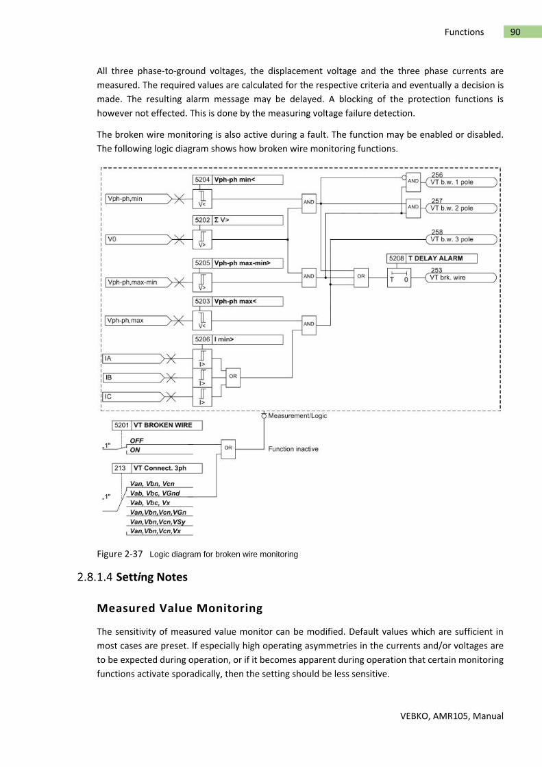
VEBKO, AMR105, Manual
90 Functions
All three phase-to-ground voltages, the displacement voltage and the three phase currents are
measured. The required values are calculated for the respective criteria and eventually a decision is
made. The resulting alarm message may be delayed. A blocking of the protection functions is
however not effected. This is done by the measuring voltage failure detection.
The broken wire monitoring is also active during a fault. The function may be enabled or disabled.
The following logic diagram shows how broken wire monitoring functions.
Figure 2-37 Logic diagram for broken wire monitoring
Setting Notes
Measured Value Monitoring
The sensitivity of measured value monitor can be modified. Default values which are sufficient in
most cases are preset. If especially high operating asymmetries in the currents and/or voltages are
to be expected during operation, or if it becomes apparent during operation that certain monitoring
functions activate sporadically, then the setting should be less sensitive.

VEBKO, AMR105, Manual
91 Functions
Address 8102 BALANCE V-LIMIT determines the limit voltage (phase-to-phase) above which the
voltage symmetry monitor is effective. Address 8103 BAL. FACTOR V is the associated symmetry
factor; that is, the slope of the symmetry characteristic curve. In address 8110 T BAL. V LIMIT you set
the delay time of fault message no. 167 „Fail V balance“.
Address 8104 BALANCE I LIMIT determines the limit current above which the current symmetry
monitor is effective. Address 8105 BAL. FACTOR I is the associated symmetry factor; that is, the slope
of the symmetry characteristic curve. In address 8111 T BAL. I LIMIT you set the delay time for fault
message no. 163 „Fail I balance“.
Address 8106 Σ I THRESHOLD determines the limit current above which the current sum monitoring
is activated (absolute portion, only relative to INom). The relative portion (relative to the maximum
conductor current) for activating the current sum monitor is set at address 8107 Σ I FACTOR.
Note
Current sum monitoring can operate properly only when the residual current of the protected line is
fed to the fourth current input (IN) of the relay. Furthermore, the fourth current input (IN) may not
be sensitive.
Note
The connections of the ground paths and their adaption factors were set when configuring the
general Power System Data. These settings must be correct for the measured values monitoring to
function properly.
Measured value monitoring can be set to ON or OFF at address 8101 MEASURE. SUPERV.
Fuse Failure Monitor (FFM)
Via address 5301 FUSE FAIL MON. you select under which system conditions the FFM works.
Depending on that, make the required settings in the grounded system via the parameters 5302,
5303 and 5307. In a grounded/isolated system, only the parameter 5307 is relevant.
The settings for the fuse failure monitor must be selected in such manner that reliable activation
occurs if a phase voltage fails, but that false activation does not occur during ground faults in a
grounded network. Address 5303 FUSE FAIL RESID must be set as sensitive as required (with ground
faults, below the smallest fault current).
The FFM picks up if the ground voltage VN is higher than the set limit value under address 5302 FUSE
FAIL 3Vo and if the ground current IN lies below the set limit value under address 5303 FUSE FAIL
RESID.
In order to detect a three-phase failure, the progress in time of current and voltage is monitored. If
the voltage sinks below the threshold value without a change in the current value, a three-phase
failure is detected. This threshold value of the current element must be set under address 5307 I>
BLOCK. The threshold value should be identical with the definite time overcurrent protection.
Under address 5310 BLOCK PROT. it can be determined whether the protection functions should be
blocked upon pickup by the FFM.
Note

VEBKO, AMR105, Manual
92 Functions
The setting under address 5310 BLOCK PROT. has no effect on the flexible protection functions. A
separate blocking can be selected for that purpose.
The function may be disabled in address 5301 FUSE FAIL MON., e.g. when performing asymmetrical
tests.
Settings
The table indicates region-specific default settings. Column C (configuration) indicates the
corresponding secondary nominal current of the current transformer.
Adr. Parameter C Setting options Default Setting
5301 Fuse Fail Monitor OFF ON-(solid Grounded power system) ON-(Peterson-Coil Grounded/isolated)
OFF
5310 Block Protection by FFM YES NO
YES
8101 Measurment Supervision ON OFF
ON
8109 Fast Summated Current Monitoring
ON OFF
ON
5201 VT broken wire supervision ON OFF
OFF
5302 Zero Sequence Voltage 10:1:100[V] 30
5303 Residual Current(For CT 1A) 1A 0.10:0.01:1.00[A] 0.10
9841 Residual Current(For CT 5A) 5A 0.50:0.01:5.00[A] 0.50
5307 I> Pickup for Block FFM 0.10:0.01:35.00,oo[A] 1.00
8102 Voltage Threshold for Balance Monitoring
10:1:100[V] 50
8103 Balance Factor for Voltage Monitor
0.58:0.01:0.90[] 0.75
8104 Current Threshold for Balance Monitoring
1A 0.10:0.01:1.00[A] 0.50
9842 Current Threshold for Balance Monitoring
5A 0.50:0.01:5.00[A] 0.50
8105 Balance Factor For Current Monitor
0.10:0.01:0.90[A] 0.50
8106 Summated Current Monitoring Threshold
1A 0.05:0.01:2.00,oo[A] 0.10
9843 Summated Current Monitoring Threshold
5A 0.25:0.01:10.00,oo[A] 0.25
8107 Summated Current Monitoring Factor
0.00:0.01:0.95[] 0.10
8110 T Balance Factor for Voltage Monitor
0:1:100[sec] 5
8111 T Current Balance Monitor 0:1:100[sec] 5
5202 Threshold voltage sum 1.0:0.1:100.0[V] 8.0
5203 Maximum phase to Phase Voltage 1.0:0.1:100.0[V] 16.0
5204 Minimum Phase to Phase Voltage 1.0:0.1:100.0[V] 16.0
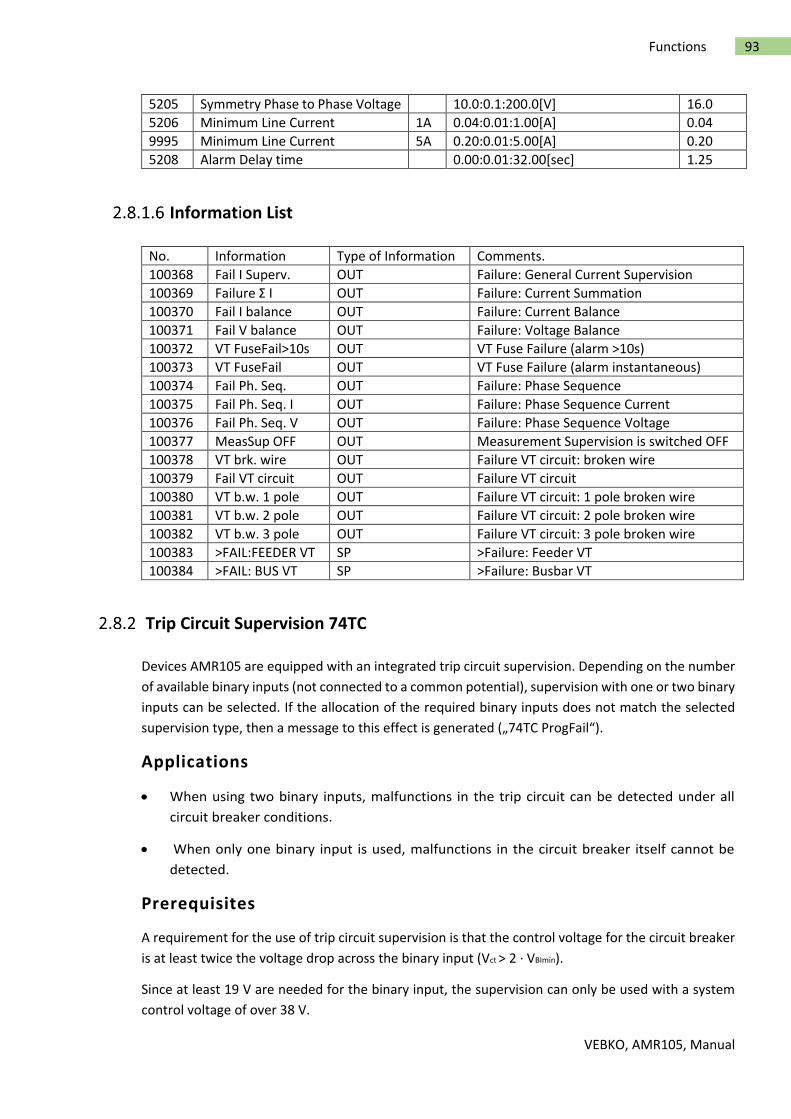
VEBKO, AMR105, Manual
93 Functions
5205 Symmetry Phase to Phase Voltage 10.0:0.1:200.0[V] 16.0
5206 Minimum Line Current 1A 0.04:0.01:1.00[A] 0.04
9995 Minimum Line Current 5A 0.20:0.01:5.00[A] 0.20
5208 Alarm Delay time 0.00:0.01:32.00[sec] 1.25
Information List
No. Information Type of Information Comments.
100368 Fail I Superv. OUT Failure: General Current Supervision
100369 Failure Σ I OUT Failure: Current Summation
100370 Fail I balance OUT Failure: Current Balance
100371 Fail V balance OUT Failure: Voltage Balance
100372 VT FuseFail>10s OUT VT Fuse Failure (alarm >10s)
100373 VT FuseFail OUT VT Fuse Failure (alarm instantaneous)
100374 Fail Ph. Seq. OUT Failure: Phase Sequence
100375 Fail Ph. Seq. I OUT Failure: Phase Sequence Current
100376 Fail Ph. Seq. V OUT Failure: Phase Sequence Voltage
100377 MeasSup OFF OUT Measurement Supervision is switched OFF
100378 VT brk. wire OUT Failure VT circuit: broken wire
100379 Fail VT circuit OUT Failure VT circuit
100380 VT b.w. 1 pole OUT Failure VT circuit: 1 pole broken wire
100381 VT b.w. 2 pole OUT Failure VT circuit: 2 pole broken wire
100382 VT b.w. 3 pole OUT Failure VT circuit: 3 pole broken wire
100383 >FAIL:FEEDER VT SP >Failure: Feeder VT
100384 >FAIL: BUS VT SP >Failure: Busbar VT
Trip Circuit Supervision 74TC
Devices AMR105 are equipped with an integrated trip circuit supervision. Depending on the number
of available binary inputs (not connected to a common potential), supervision with one or two binary
inputs can be selected. If the allocation of the required binary inputs does not match the selected
supervision type, then a message to this effect is generated („74TC ProgFail“).
Applications
When using two binary inputs, malfunctions in the trip circuit can be detected under all
circuit breaker conditions.
When only one binary input is used, malfunctions in the circuit breaker itself cannot be
detected.
Prerequisites
A requirement for the use of trip circuit supervision is that the control voltage for the circuit breaker
is at least twice the voltage drop across the binary input (Vct > 2 · VBImin).
Since at least 19 V are needed for the binary input, the supervision can only be used with a system
control voltage of over 38 V.

VEBKO, AMR105, Manual
94 Functions
Description
Supervision with Two Binary Inputs
When using two binary inputs, these are connected according to Figure 2-38, parallel to the
associated trip contact on one side, and parallel to the circuit breaker auxiliary contacts on the other.
Figure 2-38 Principle of the trip circuit supervision with two binary inputs
Supervision with two binary inputs not only detects interruptions in the trip circuit and loss of control
voltage, it also supervises the response of the circuit breaker using the position of the circuit breaker
auxiliary contacts. Depending on the conditions of the trip contact and the circuit breaker, the binary
inputs are activated (logical condition "H" in Table 2-7), or not activated (logical condition "L").
In healthy trip circuits the condition that both binary inputs are not actuated (”L") is only possible
during a short transition period (trip contact is closed but the circuit breaker has not yet opened). A
continuous state of this condition is only possible when the trip circuit has been interrupted, a short-
circuit exists in the trip circuit, a loss of battery voltage occurs, or malfunctions occur with the circuit
breaker mechanism. Therefore, it is used as supervision criterion.
Table 2-7 Condition table for binary inputs, depending on RTC and CB position
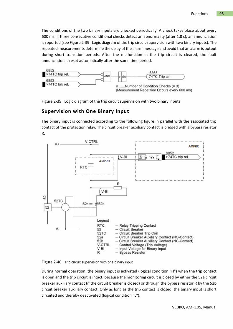
VEBKO, AMR105, Manual
95 Functions
The conditions of the two binary inputs are checked periodically. A check takes place about every
600 ms. If three consecutive conditional checks detect an abnormality (after 1.8 s), an annunciation
is reported (see Figure 2-39 Logic diagram of the trip circuit supervision with two binary inputs). The
repeated measurements determine the delay of the alarm message and avoid that an alarm is output
during short transition periods. After the malfunction in the trip circuit is cleared, the fault
annunciation is reset automatically after the same time period.
Figure 2-39 Logic diagram of the trip circuit supervision with two binary inputs
Supervision with One Binary Input
The binary input is connected according to the following figure in parallel with the associated trip
contact of the protection relay. The circuit breaker auxiliary contact is bridged with a bypass resistor
R.
Figure 2-40 Trip circuit supervision with one binary input
During normal operation, the binary input is activated (logical condition "H") when the trip contact
is open and the trip circuit is intact, because the monitoring circuit is closed by either the 52a circuit
breaker auxiliary contact (if the circuit breaker is closed) or through the bypass resistor R by the 52b
circuit breaker auxiliary contact. Only as long as the trip contact is closed, the binary input is short
circuited and thereby deactivated (logical condition "L").

VEBKO, AMR105, Manual
96 Functions
If the binary input is continuously deactivated during operation, this leads to the conclusion that
there is an interruption in the trip circuit or loss of control voltage.
As the trip circuit supervision does not operate during system faults, the closed trip contact does not
lead to a fault message. If, however, tripping contacts from other devices operate in parallel with the
trip circuit, then the fault message must be delayed (see also Figure 2-41). The delay time can be set
via parameter 8202 Alarm
Delay. A message is only released after expiry of this time. After clearance of the fault in the trip
circuit, the fault message is automatically reset.
Figure 2-41 Logic diagram of trip circuit supervision with one binary input
The following figure shows the logic diagram for the message that can be generated by the trip circuit
monitor, depending on the control settings and binary inputs.
Figure 2-42 Message logic for trip circuit supervision
Setting Notes
General
The function is only effective and accessible if address 182 was set to either 2 Binary Inputs or 1
Binary Input during configuration, the appropriate number of binary inputs has been configured
accordingly for this purpose and the function FCT 74TC is ON at address 8201. If the allocation of the
required binary inputs does not match the selected supervision type, a message to this effect is
generated („74TC ProgFail“). If the trip circuit monitor is not to be used at all, then Disabled is set at
address 182.
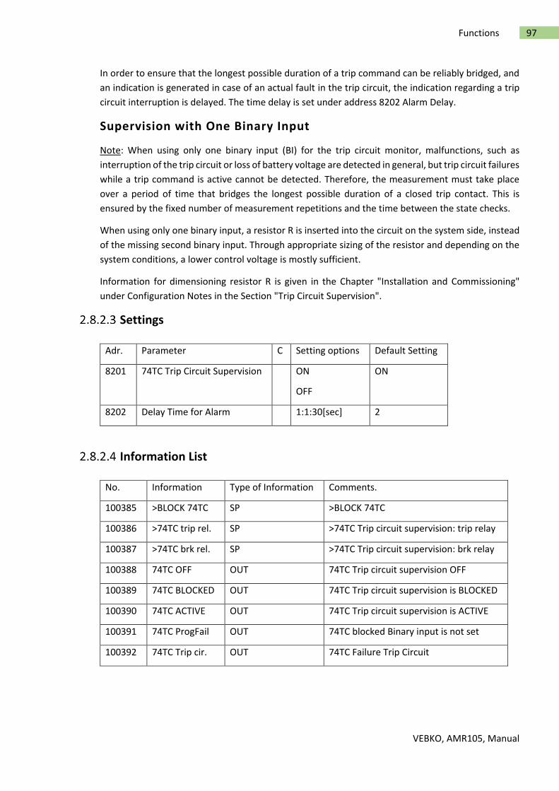
VEBKO, AMR105, Manual
97 Functions
In order to ensure that the longest possible duration of a trip command can be reliably bridged, and
an indication is generated in case of an actual fault in the trip circuit, the indication regarding a trip
circuit interruption is delayed. The time delay is set under address 8202 Alarm Delay.
Supervision with One Binary Input
Note: When using only one binary input (BI) for the trip circuit monitor, malfunctions, such as
interruption of the trip circuit or loss of battery voltage are detected in general, but trip circuit failures
while a trip command is active cannot be detected. Therefore, the measurement must take place
over a period of time that bridges the longest possible duration of a closed trip contact. This is
ensured by the fixed number of measurement repetitions and the time between the state checks.
When using only one binary input, a resistor R is inserted into the circuit on the system side, instead
of the missing second binary input. Through appropriate sizing of the resistor and depending on the
system conditions, a lower control voltage is mostly sufficient.
Information for dimensioning resistor R is given in the Chapter "Installation and Commissioning"
under Configuration Notes in the Section "Trip Circuit Supervision".
Settings
Adr. Parameter C Setting options Default Setting
8201 74TC Trip Circuit Supervision ON
OFF
ON
8202 Delay Time for Alarm 1:1:30[sec] 2
Information List
No. Information Type of Information Comments.
100385 >BLOCK 74TC SP >BLOCK 74TC
100386 >74TC trip rel. SP >74TC Trip circuit supervision: trip relay
100387 >74TC brk rel. SP >74TC Trip circuit supervision: brk relay
100388 74TC OFF OUT 74TC Trip circuit supervision OFF
100389 74TC BLOCKED OUT 74TC Trip circuit supervision is BLOCKED
100390 74TC ACTIVE OUT 74TC Trip circuit supervision is ACTIVE
100391 74TC ProgFail OUT 74TC blocked Binary input is not set
100392 74TC Trip cir. OUT 74TC Failure Trip Circuit

VEBKO, AMR105, Manual
98 Functions
Breaker Failure Protection 50BF
The breaker failure protection function monitors proper tripping of the relevant circuit breaker.
Description
General
If after a programmable time delay, the circuit breaker has not opened, breaker failure protection
issues a trip signal to isolate the failure breaker by tripping other surrounding backup circuit breaker
(see example in the figure below).
Figure 2-43 Function principle of the breaker failure protection
Initiation
The breaker failure protection function can be initiated by two different sources:
Trip signals of internal protective functions of the AMR105,
external trip signals via binary inputs („>50BF ext SRC“).
For each of the two sources, a unique pickup message is generated, a unique time delay is initiated,
and aunique trip signal is generated. The setting values of current threshold and delay time apply to
both sources.
Criteria
There are two criteria for breaker failure detection:
Check whether the current flow has effectively disappeared after a tripping command was
issued,
Evaluate the circuit breaker's auxiliary contacts.

VEBKO, AMR105, Manual
99 Functions
The criteria used to determine if the circuit breaker has operated are selectable and also depend on
the protection function that initiated the breaker failure function. On tripping without fault current,
e.g. via voltage protection, the current below the threshold 50BF PICKUP is not a reliable indication
of the proper functioning of the circuit breaker. In such cases, pickup exclusively depends on the
auxiliary contact criterion. In protection functions based on the measurement of currents (including
all short-circuit protection functions), the current flow is a preferential criterion, i.e. it is given
priority, as opposed to the auxiliary contacts. If current flows above the set threshold or thresholds
(enabled w/ 3I0>) are detected, the breaker failure protection trips even if the auxiliary criterion
indicates „Breaker Open“.
Monitoring of the Current Flow
Address 170 50BF can be set in such a way that either the current criterion can already be met by a
single phase current (setting Enabled) or that another current is taken into consideration in order to
check the plausibility (setting enabled w/ 3I0>), see Figure .
The currents are filtered through numerical filters to evaluate only the fundamental harmonic. They
are monitored and compared to the set threshold values. Besides the three phase currents, two
additional currents are provided to enable a plausibility check. Separate threshold values can be used
for this plausibility check if this is configured accordingly. To detect ground faults more quickly, the
threshold value for the ground current can also be used for checking the plausibility of the phase
currents. This function is activated via binary input „>50BFactiv.3I0>“ (see Figure 2-46).
The ground current IN (3·I0) is preferably used as plausibility current. Via the parameters 613 you
decide whether the measured (Ignd (measured)) or the calculated (3I0 (calcul.)) values are to be used.
In case of system faults not involving ground currents, no increased ground currents/residual
currents are flowing, and therefore the calculated triple negative sequence current 3·I2 or a second
phase current is used as plausibility current.

VEBKO, AMR105, Manual
100 Functions
Figure 2-44 Monitoring of the current flow
Monitoring of the Circuit Breaker Auxiliary Contacts
Evaluation of the circuit breaker's auxiliary contacts depends on the type of contacts, and how they
are connected to the binary inputs:
the auxiliary contacts for circuit breaker "open" (4602 „>52-b“) and "closed" (4601 „>52-a“)
are configured,
only the auxiliary contact for circuit breaker "open" is configured(4602 „>52-b“),
only the auxiliary contact for circuit breaker "closed" is configured (4601 „>52-a“),
none of the two auxiliary contacts is configured.
Feedback information of the auxiliary status of the circuit breaker is evaluated, depending on the
allocation of binary inputs and auxiliary contacts. After a trip command has been issued it is the aim
to detect — if possible — by means of the feedback of the circuit breaker's auxiliary contacts whether
the breaker is open or in intermediate position. If valid, this information can be used for a proper
initiation of the breaker failure protection function.
The logic diagram illustrates the monitoring of the circuit breaker's auxiliary contacts.
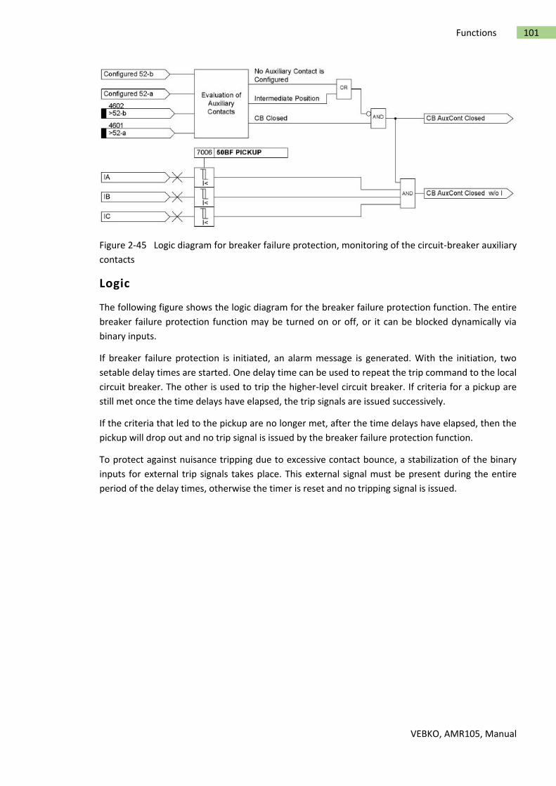
VEBKO, AMR105, Manual
101 Functions
Figure 2-45 Logic diagram for breaker failure protection, monitoring of the circuit-breaker auxiliary
contacts
Logic
The following figure shows the logic diagram for the breaker failure protection function. The entire
breaker failure protection function may be turned on or off, or it can be blocked dynamically via
binary inputs.
If breaker failure protection is initiated, an alarm message is generated. With the initiation, two
setable delay times are started. One delay time can be used to repeat the trip command to the local
circuit breaker. The other is used to trip the higher-level circuit breaker. If criteria for a pickup are
still met once the time delays have elapsed, the trip signals are issued successively.
If the criteria that led to the pickup are no longer met, after the time delays have elapsed, then the
pickup will drop out and no trip signal is issued by the breaker failure protection function.
To protect against nuisance tripping due to excessive contact bounce, a stabilization of the binary
inputs for external trip signals takes place. This external signal must be present during the entire
period of the delay times, otherwise the timer is reset and no tripping signal is issued.

VEBKO, AMR105, Manual
102 Functions
Figure 2-46 Logic diagram of the breaker failure protection
Setting Notes
General
Breaker failure protection is only effective and accessible if address 170 50BF is set to Enabled or
enabled w/ 3I0>. Setting Enabled considers the three phase currents for total current monitoring.
Setting enabled w/ 3I0> additionally evaluates the ground current or the negative sequence system
when only one phase current occurs.
If this function is not required, then Disabled is set. The function can be set to ON or OFF under
address 7001 FCT 50BF.
Criteria
Address 7004 Chk BRK CONTACT establishes whether or not the breaker auxiliary contacts connected
via binary inputs are to be used as a criterion for pickup. If this address is set to ON, then current
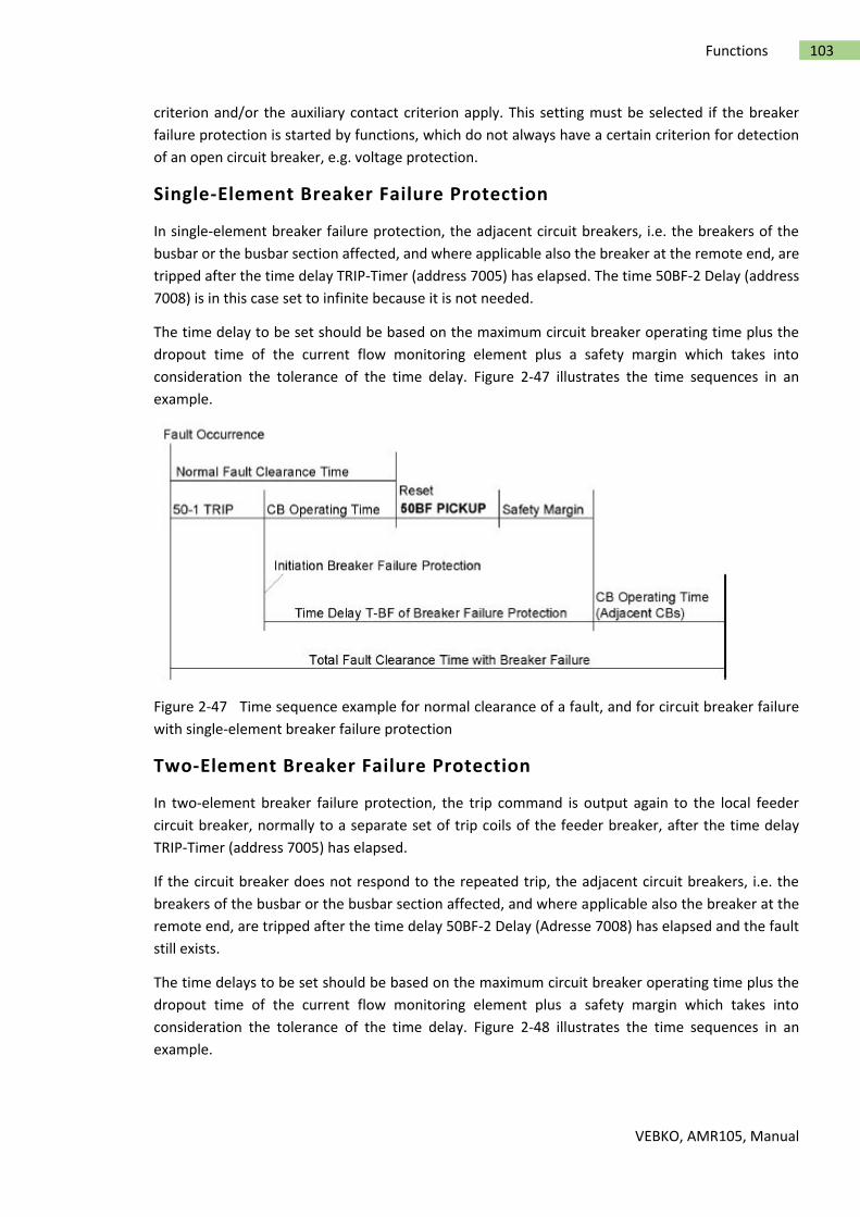
VEBKO, AMR105, Manual
103 Functions
criterion and/or the auxiliary contact criterion apply. This setting must be selected if the breaker
failure protection is started by functions, which do not always have a certain criterion for detection
of an open circuit breaker, e.g. voltage protection.
Single-Element Breaker Failure Protection
In single-element breaker failure protection, the adjacent circuit breakers, i.e. the breakers of the
busbar or the busbar section affected, and where applicable also the breaker at the remote end, are
tripped after the time delay TRIP-Timer (address 7005) has elapsed. The time 50BF-2 Delay (address
7008) is in this case set to infinite because it is not needed.
The time delay to be set should be based on the maximum circuit breaker operating time plus the
dropout time of the current flow monitoring element plus a safety margin which takes into
consideration the tolerance of the time delay. Figure 2-47 illustrates the time sequences in an
example.
Figure 2-47 Time sequence example for normal clearance of a fault, and for circuit breaker failure
with single-element breaker failure protection
Two-Element Breaker Failure Protection
In two-element breaker failure protection, the trip command is output again to the local feeder
circuit breaker, normally to a separate set of trip coils of the feeder breaker, after the time delay
TRIP-Timer (address 7005) has elapsed.
If the circuit breaker does not respond to the repeated trip, the adjacent circuit breakers, i.e. the
breakers of the busbar or the busbar section affected, and where applicable also the breaker at the
remote end, are tripped after the time delay 50BF-2 Delay (Adresse 7008) has elapsed and the fault
still exists.
The time delays to be set should be based on the maximum circuit breaker operating time plus the
dropout time of the current flow monitoring element plus a safety margin which takes into
consideration the tolerance of the time delay. Figure 2-48 illustrates the time sequences in an
example.

VEBKO, AMR105, Manual
104 Functions
Figure 2-48 Time sequence example for normal clearance of a fault, and for circuit breaker failure
with two-element breaker failure protection
Pickup Values
The pickup value of the current flow monitoring is set under address 7006 50BF PICKUP, and the
pickup value of the ground current monitoring under address 7007 50BF PICKUP IE>. The threshold
values must be set at a level below the minimum fault current for which the total current monitoring
must operate. A setting of 10 % below the minimum fault current for which breaker failure protection
must operate is recommended. The pickup value should not be set too low since otherwise there is
a risk that transients in the current transformer secondary circuit may lead to extended dropout
times if extremely high currents are switched off.
Via binary input 1404 „>50BFactiv.3I0>“ you can activate the threshold value 50BF PICKUP IE> also
for checking the plausibility of the phase currents.
Settings
The table indicates region-specific default settings. Column C (configuration) indicates the
corresponding secondary nominal current of the current transformer.
Adr. Parameter C Setting options Default Setting
7001 50BF Breaker Failure Protecion ON
OFF
OFF
7004 Check Breaker contacts ON
OFF
OFF
7005 Trip-Timer 0.06:0.01:60.00,oo[sec] 0.25
7006 50BF Pickup Current Threshold 1A 0.03:0.01:20.00[A] 0.10
9860 50BF Pickup Current Threshold 5A 0.15:0.01:100.00[A] 0.15
7007 50BF Pickp earth Current Threshold 0.03:0.01:20.00[A] 0.10
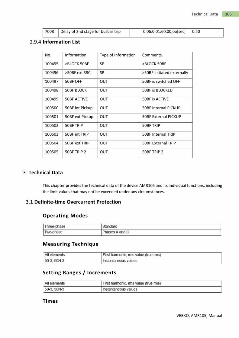
VEBKO, AMR105, Manual
105 Technical Data
7008 Delay of 2nd stage for busbar trip 0.06:0.01:60.00,oo[sec] 0.50
Information List
No. Information Type of Information Comments.
100495 >BLOCK 50BF SP >BLOCK 50BF
100496 >50BF ext SRC SP >50BF initiated externally
100497 50BF OFF OUT 50BF is switched OFF
100498 50BF BLOCK OUT 50BF is BLOCKED
100499 50BF ACTIVE OUT 50BF is ACTIVE
100500 50BF int Pickup OUT 50BF Internal PICKUP
100501 50BF ext Pickup OUT 50BF External PICKUP
100502 50BF TRIP OUT 50BF TRIP
100503 50BF int TRIP OUT 50BF Internal TRIP
100504 50BF ext TRIP OUT 50BF External TRIP
100505 50BF TRIP 2 OUT 50BF TRIP 2
Technical Data
This chapter provides the technical data of the device AMR105 and its individual functions, including
the limit values that may not be exceeded under any circumstances.
Definite-time Overcurrent Protection
Operating Modes
Measuring Technique
Setting Ranges / Increments
Times
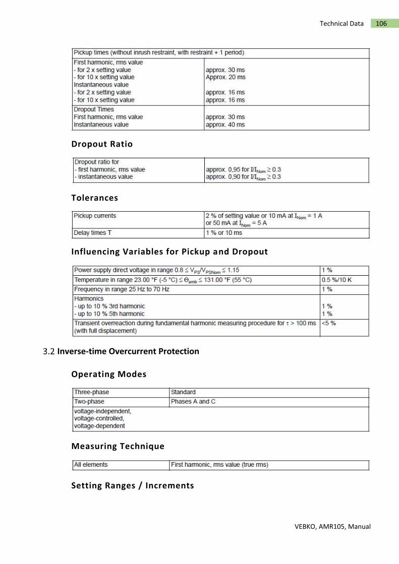
VEBKO, AMR105, Manual
106 Technical Data
Dropout Ratio
Tolerances
Influencing Variables for Pickup and Dropout
Inverse-time Overcurrent Protection
Operating Modes
Measuring Technique
Setting Ranges / Increments

VEBKO, AMR105, Manual
107 Technical Data
Trip Time Curves acc. to IEC
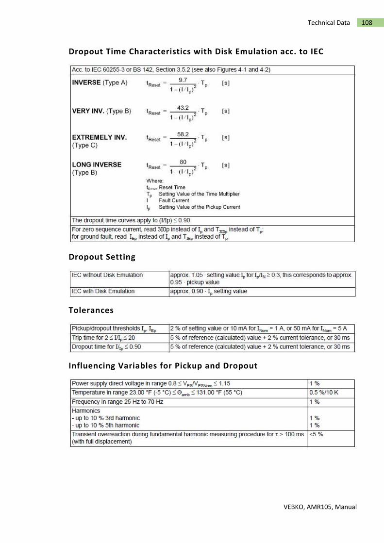
VEBKO, AMR105, Manual
108 Technical Data
Dropout Time Characteristics with Disk Emulation acc. to IEC
Dropout Setting
Tolerances
Influencing Variables for Pickup and Dropout

VEBKO, AMR105, Manual
109 Technical Data
Figure 3-1 Dropout time and trip time curves of the inverse time overcurrent protection, acc. to IEC

VEBKO, AMR105, Manual
110 Technical Data
Figure 3-2 Dropout time and trip time curves of the inverse time overcurrent protection, acc. to IEC
Trip Time Curves acc. to ANSI

VEBKO, AMR105, Manual
111 Technical Data

VEBKO, AMR105, Manual
112 Technical Data
Dropout Time Characteristics with Disk Emulation acc. to ANSI/IEEE
Dropout Setting
Tolerances

VEBKO, AMR105, Manual
113 Technical Data
Influencing Variables for Pickup and Dropout

VEBKO, AMR105, Manual
114 Technical Data
Figure 3-3 Dropout time and trip time curves of the inverse time overcurrent protection, acc. to
ANSI/IEEE
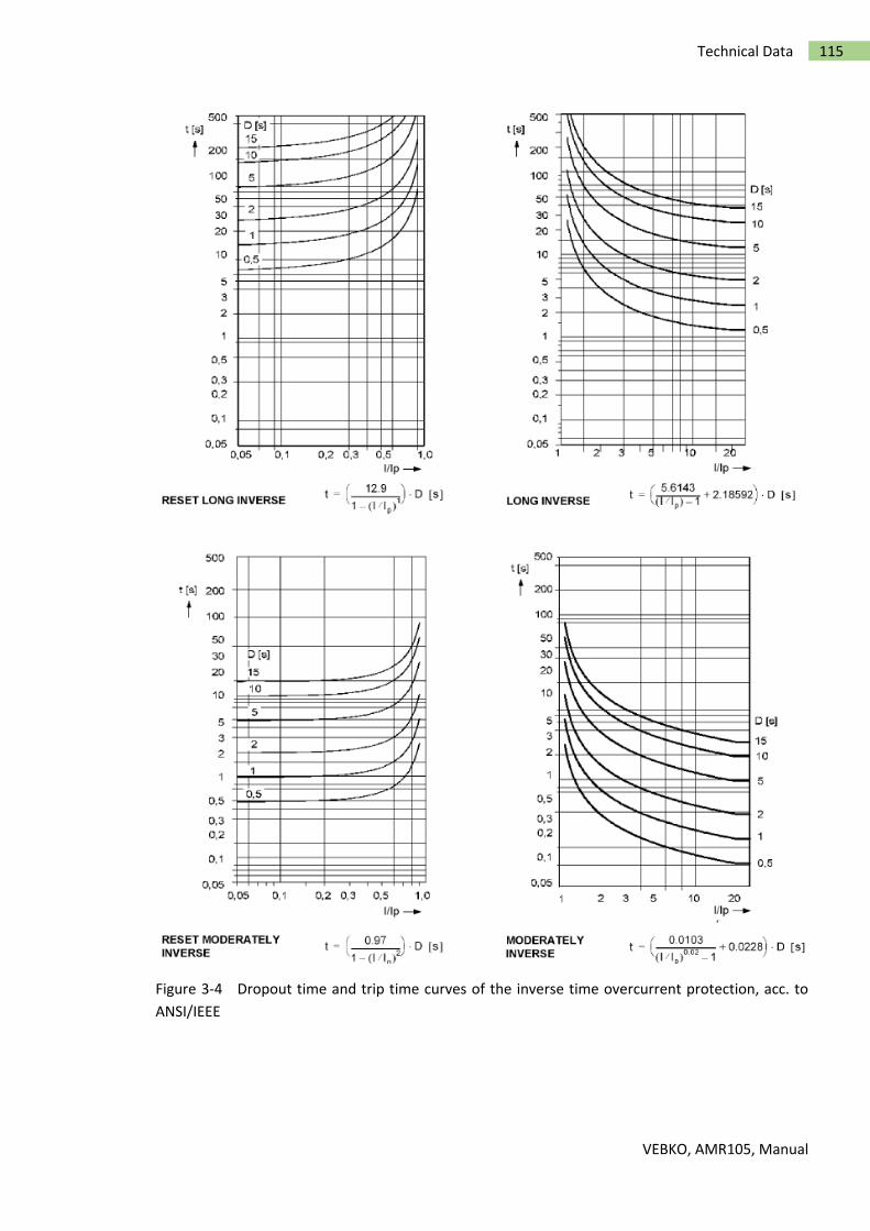
VEBKO, AMR105, Manual
115 Technical Data
Figure 3-4 Dropout time and trip time curves of the inverse time overcurrent protection, acc. to
ANSI/IEEE

VEBKO, AMR105, Manual
116 Technical Data
Figure 3-5 Dropout time and trip time curves of the inverse time overcurrent protection, acc. to
ANSI/IEEE

VEBKO, AMR105, Manual
117 Technical Data
Figure 3-6 Dropout time and trip time curve of the inverse time overcurrent protection, acc. to
ANSI/IEEE
Directional Overcurrent Protection
Time Overcurrent Elements
Determination of Direction
For Phase Faults
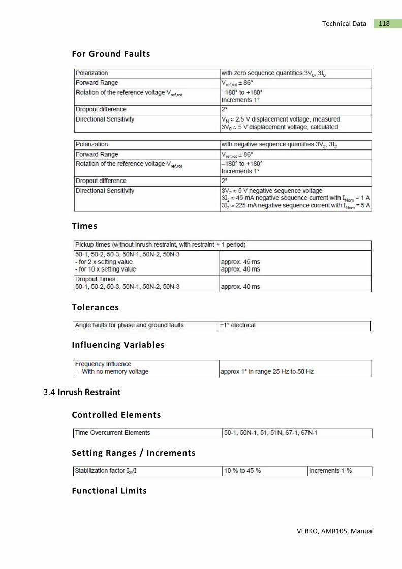
VEBKO, AMR105, Manual
118 Technical Data
For Ground Faults
Times
Tolerances
Influencing Variables
Inrush Restraint
Controlled Elements
Setting Ranges / Increments
Functional Limits

VEBKO, AMR105, Manual
119 Technical Data
Crossblock
Dynamic Cold Load Pickup
Timed Changeover of Settings
Setting Ranges / Increments
Single-phase Overcurrent Protection
Current Elements

VEBKO, AMR105, Manual
120 Technical Data
Operating Times
Dropout Ratios
Tolerances
Influencing Variables for the Pickup Values
Voltage Protection
Setting Ranges / Increments

VEBKO, AMR105, Manual
121 Technical Data
Times

VEBKO, AMR105, Manual
122 Technical Data
Tolerances
Influencing Variables
Negative Sequence Protection (definite-time characteristic)
Setting Ranges / Increments
Functional Limit
Times
Dropout Ratio

VEBKO, AMR105, Manual
123 Technical Data
Tolerances
Influencing Variables for Pickup Values
Negative Sequence Protection (inverse-time characteristics)
Setting Ranges / Increments
Functional Limit
Trip Time Curves acc. to IEC

VEBKO, AMR105, Manual
124 Technical Data
Trip Time Curves acc. to ANSI
Tolerances
Dropout Time Curves with Disk Emulation acc. to ANSI

VEBKO, AMR105, Manual
125 Technical Data
Dropout Value
Tolerances
Influencing Variables for Pickup Values
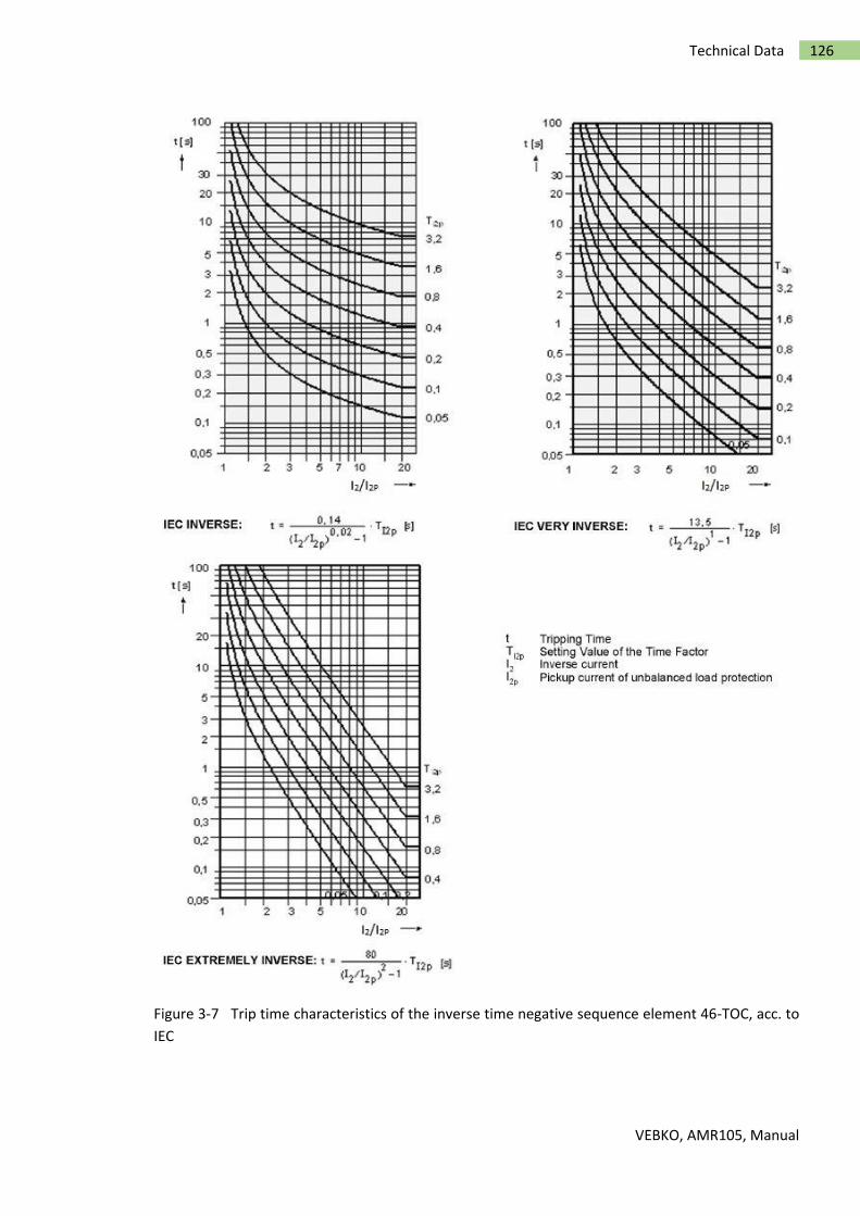
VEBKO, AMR105, Manual
126 Technical Data
Figure 3-7 Trip time characteristics of the inverse time negative sequence element 46-TOC, acc. to
IEC

VEBKO, AMR105, Manual
127 Technical Data
Figure 3-8 Dropout time and trip time characteristics of the inverse time unbalanced load stage, acc.
to ANSI
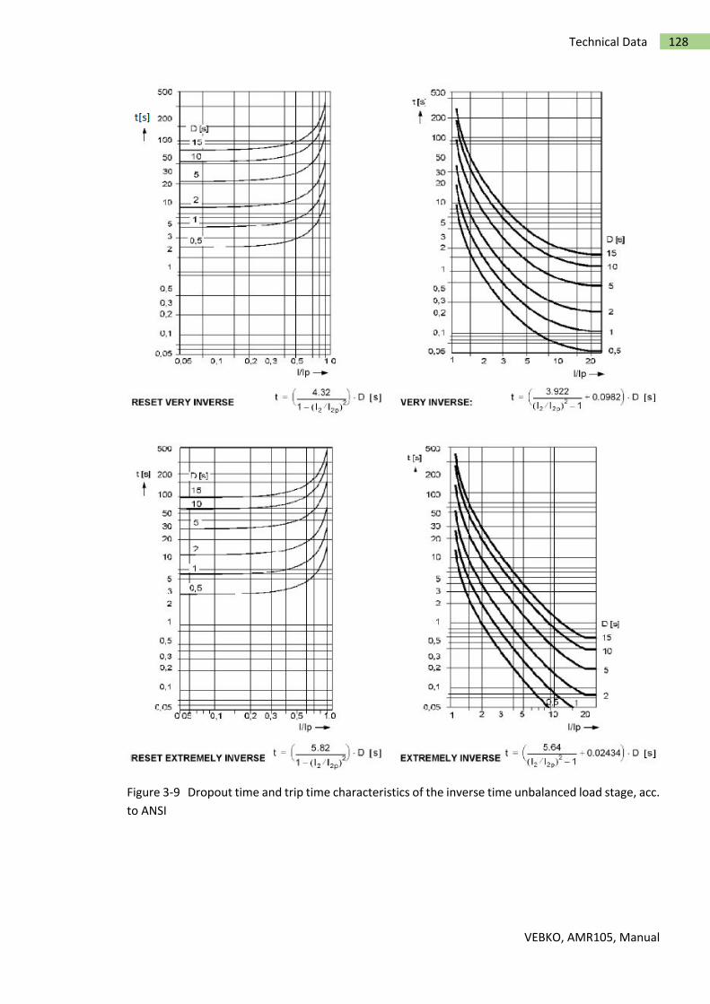
VEBKO, AMR105, Manual
128 Technical Data
Figure 3-9 Dropout time and trip time characteristics of the inverse time unbalanced load stage, acc.
to ANSI