multi-field processing of micro-platelets for …
TRANSCRIPT

1
`Proceedings of the ASME 2018 Conference on Smart Materials, Adaptive Structures and Intelligent Systems SMASIS2018
September 10-12, 2018, San Antonio, Texas, USA
SMASIS2018-8080
MULTI-FIELD PROCESSING OF MICRO-PLATELETS FOR MAGNETO-ACTIVE APPLICATIONS
Md Abdulla Al Masud Zoubeida Ounaies Paris von Lockette
Department of Mechanical and Nuclear Engineering The Pennsylvania State University
State College, PA 16801
ABSTRACT
The orientation and spatial distribution of magnetic particles in smart mechano-magnetic composites are key to enhancing their actuation capability. In this study, we present a new experimental approach to tune the orientation and assembly of barium hexaferrite (BHF) micro-platelets in liquid polymers by applying uniform magnetic and alternating current (AC)-electric fields. First, we investigated the assembly of BHFs under different electric field amplitudes and frequencies in the silicone elastomer. After establishing the optimum parameters for electric and magnetic alignment, four different microstructures are fabricated namely (a) random (b) electrically aligned (c) magnetically aligned and (d) simultaneously electrically and magnetically aligned. Finally, microstructural and property characterizations are performed using OM, XRD, SEM, and VSM measurements. Our findings demonstrate that a variety of microstructures can be obtained depending on the nature of the applied external field: in the absence of any field, BHF platelets are organized as small stacks, owing to their intrinsic magnetic polarization. In contrast, application of an electric field creates chain-like structures where the orientation of the BHF stacks inside the chains is random. Application of a magnetic field enhances rotation of the BHF stacks, which are found to rotate inside the chain in directions dictated by the magnetic field. Finally, by applying simultaneous electric and magnetic fields while also tuning the processing parameters, BHF-composite film with a squareness ratio of 0.92 is obtained. In order to further extend the actuation capability of resulting composites, we will also experiment with electroactive polymer matrices such as
P(VDF–TrFE–CTFE) terpolymer to fabricate a multiferroic material that can actuate under both electric and magnetic field. INTRODUCTION
Magneto-active polymer-based composites are excellent choices in aerospace, automobile, biomedical and origami applications for their low density and high flexibility combined with high sensing and actuation capabilities. In order to enhance their actuation capabilities, higher concentration of magnetic fillers is desirable. However, adding higher content of fillers leads to agglomeration and often degrades the properties [1]. Another way to enhance composite properties is to assemble relatively low concentration of particles inside the matrix to make an anisotropic composite with enhanced properties in the direction of alignment. Previous studies demonstrate the assembly of magnetic particles primarily by magnetic fields [2]–[6]. However, another approach to particle assembly involving electric fields has been widely used in biomedical and biological applications to sort DNA, viruses, blood cells, cancer cells etc. [7]. Electric field has also been successfully used to manipulate metal oxide particles [8], carbon nanotubes [9], [10] and piezoelectric fibers [11]–[14] to make anisotropic composites. In our previous work [15-16], we demonstrate the electric field manipulation of geometrically and magnetically anisotropic hard M-type BHF micro and nano platelets. We observe that applying just electric field to align anisotropic magnetic particles leads to chain-like structures, but the net magnetic moment remains zero, since within the chains,
2
individual particles are oriented randomly. However, if we concurrently introduce a magnetic field, the rotation of the particles can be controlled and, in this way, particles can be oriented inside the chain in directions dictated by the magnetic field. In this article, we present a new experimental approach where BHFs platelets are assembled in both macro and micro-scale using simultaneous application of alternating current (AC)-electric fields and a uniform magnetic field. We demonstrate that by tailoring the electric and magnetic field conditions together with the processing parameters, BHF-composite films with a squareness ratio of ~ 92% can be obtained. EXPERIMENTAL
In this study, electric and magnetic fields are employed to create anisotropic composites of Barium Hexaferrite (BHF) in polydimethylsiloxane (PDMS) elastomer. We examined four cases of the BHF-PDMS composites, namely (a) case 1: random (b) case 2: electrically aligned (c) case 3: magnetically aligned, (d) case 4: electrically and magnetically aligned. Material PDMS is prepared using Sylgard-184 silicone elastomer kit which is purchased from Dow Corning. Polyethylene glycol and n-heptane are purchased from Sigma Aldrich and used without further purification. Barium Hexaferrite platelets (BHF) are purchased from ESPI metal. The average lateral dimension of the platelets is 1085 nm with thickness of 150 nm. Table 1 shows the properties of the materials used in this study. Table 1: Properties of the materials used
Properties Value Dielectric permittivity of BHF [17] 32 Dielectric permittivity of PDMS 2.67 Remanent magnetization of BHF 40 emu/gm Saturation magnetization of BHF 72 emu/gm Coercivity of BHF 4000 Oe Viscosity of PDMS 3.5 Pa.s
Fabrication Homogenous BHF-PDMS suspensions are prepared by adding 5wt% (0.9 vol%) BHF to PDMS and dispersing via probe sonication until no sedimentation or agglomerates (>20 micron) are observed using OM. Polyethylene glycol (PEG) is added at 1:5 ratio of fillers as a surface modifier to facilitate the dispersion of BHF in PDMS. In order to have a good dispersion and BHF alignment, the viscosity of the PDMS resin is adjusted using n-heptane in a ratio of 3:10 (PDMS:n-heptane). After achieving homogenous dispersion, the curing agent is added to the BHF-PDMS slurry and the solution is stirred for another thirty minutes using a magnetic stirrer. Following this, the solution is degassed under vacuum in order to remove air
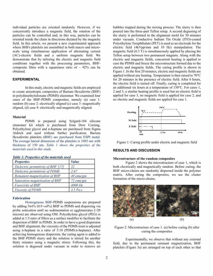
bubbles trapped during the mixing process. The slurry is then poured into the three-part Teflon setup. A second degassing of the slurry is performed in the alignment mold for 30 minutes under vacuum. Conductive Indium Tin Oxide (ITO)-coated Polyethylene Terephthalate (PET) is used as an electrode for the electric field (4kVpp/mm and 10 Hz) manipulation. The magnetic field (0.3 T) is simultaneously applied by placing the Teflon setup between two permanent magnets. Along with the electric and magnetic fields, concurrent heating is applied to cure the PDMS and freeze the microstructure formed due to the electric and magnetic fields. The curing profile is shown in Figure 1. In the first 20 minutes, electric and magnetic fields are applied without any heating. Temperature is then raised to 70°C for 20 minutes in the presence of electric field. After 6 hours, the electric field is turned off. Finally, curing is completed for an additional six hours at a temperature of 150°C. For cases 1, 2 and 3, a similar heating profile is used but no electric field is applied for case 3, no magnetic field is applied for case 2, and no electric and magnetic fields are applied for case 1.
Figure 1: Curing profile under electric and magnetic field
RESULTS AND DISCUSSION
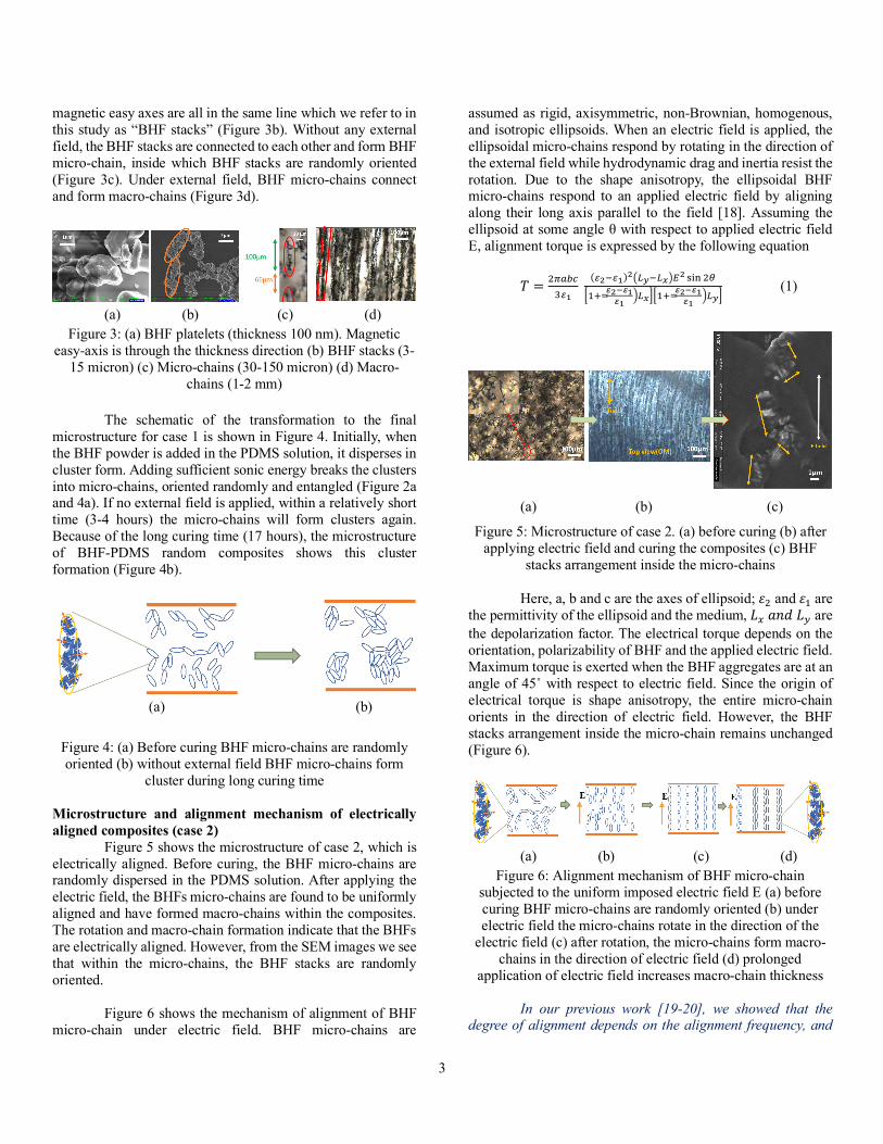
Microstructure of the random composites Figure 2 shows the microstructure of case 1, which is both electrically and magnetically random. Before curing, the BHF micro-chains are randomly dispersed inside the polymer matrix. After curing the composites, we see the cluster formation of the micro-chains.
(a) (b)
Figure 2: Microstructure of case 1. (a) before curing (b) after
curing the composites Experimentally, we observe that without any external field, due to the permanent remnant magnetization, BHF platelets (Figure 3a) are arranged on top of each other so that
3
magnetic easy axes are all in the same line which we refer to in this study as “BHF stacks” (Figure 3b). Without any external field, the BHF stacks are connected to each other and form BHF micro-chain, inside which BHF stacks are randomly oriented (Figure 3c). Under external field, BHF micro-chains connect and form macro-chains (Figure 3d).
(a) (b) (c) (d)
Figure 3: (a) BHF platelets (thickness 100 nm). Magnetic easy-axis is through the thickness direction (b) BHF stacks (3-
15 micron) (c) Micro-chains (30-150 micron) (d) Macro-chains (1-2 mm)
The schematic of the transformation to the final microstructure for case 1 is shown in Figure 4. Initially, when the BHF powder is added in the PDMS solution, it disperses in cluster form. Adding sufficient sonic energy breaks the clusters into micro-chains, oriented randomly and entangled (Figure 2a and 4a). If no external field is applied, within a relatively short time (3-4 hours) the micro-chains will form clusters again. Because of the long curing time (17 hours), the microstructure of BHF-PDMS random composites shows this cluster formation (Figure 4b).
(a) (b)
Figure 4: (a) Before curing BHF micro-chains are randomly oriented (b) without external field BHF micro-chains form
cluster during long curing time
Microstructure and alignment mechanism of electrically aligned composites (case 2) Figure 5 shows the microstructure of case 2, which is electrically aligned. Before curing, the BHF micro-chains are randomly dispersed in the PDMS solution. After applying the electric field, the BHFs micro-chains are found to be uniformly aligned and have formed macro-chains within the composites. The rotation and macro-chain formation indicate that the BHFs are electrically aligned. However, from the SEM images we see that within the micro-chains, the BHF stacks are randomly oriented. Figure 6 shows the mechanism of alignment of BHF micro-chain under electric field. BHF micro-chains are
assumed as rigid, axisymmetric, non-Brownian, homogenous, and isotropic ellipsoids. When an electric field is applied, the ellipsoidal micro-chains respond by rotating in the direction of the external field while hydrodynamic drag and inertia resist the rotation. Due to the shape anisotropy, the ellipsoidal BHF micro-chains respond to an applied electric field by aligning along their long axis parallel to the field [18]. Assuming the ellipsoid at some angle θ with respect to applied electric field E, alignment torque is expressed by the following equation 𝑇 = #$%&'
()*()-.)*)-012.1345- 678 #9
:;<=>-?>*>*@13A:;<=
>-?>*>*
@12A (1)
(a) (b) (c)
Figure 5: Microstructure of case 2. (a) before curing (b) after applying electric field and curing the composites (c) BHF
stacks arrangement inside the micro-chains Here, a, b and c are the axes of ellipsoid; 𝜀# and 𝜀;are the permittivity of the ellipsoid and the medium, 𝐿D𝑎𝑛𝑑𝐿H are the depolarization factor. The electrical torque depends on the orientation, polarizability of BHF and the applied electric field. Maximum torque is exerted when the BHF aggregates are at an angle of 45˚ with respect to electric field. Since the origin of electrical torque is shape anisotropy, the entire micro-chain orients in the direction of electric field. However, the BHF stacks arrangement inside the micro-chain remains unchanged (Figure 6).
(a) (b) (c) (d)
Figure 6: Alignment mechanism of BHF micro-chain subjected to the uniform imposed electric field E (a) before curing BHF micro-chains are randomly oriented (b) under electric field the micro-chains rotate in the direction of the
electric field (c) after rotation, the micro-chains form macro-chains in the direction of electric field (d) prolonged
application of electric field increases macro-chain thickness
In our previous work [19-20], we showed that the degree of alignment depends on the alignment frequency, and
(b)
(a)
(b)

4
we demonstrated that this dependence is particularly prominent at higher electric field magnitudes (4 kV/mm). The frequency dependence of electric field-driven rotation and chain formation indicates that the mechanism is dielectrophoresis. The dielectrophoretic force depends on the Clausius–Mossotti factor which is a function of the relative complex dielectric permittivity of the BHF and PDMS, which is where the dependence on frequency comes in [21]. After rotation, the neighboring BHF micro-chains form macro-chains along the electric field direction due to electric dipole-dipole interaction. Net interaction force between two aligned linear dipoles p, at spacing r is given by following equation [18]
𝐹JJ =(K-
#$)*LM (2)
Due to this electric dipole-dipole interaction the micro-chains will form macro-chains. From Equation 2, we see that dipole-dipole interaction force depends on the induced electrical dipole moment which get enhanced when the electric field is increased. With the increase of electric field duration, more micro-chains join to the other chains and the chain thickness gradually increases while the number of chains reduces and chain gap is enhanced (Figure 6d). Eventually, chain formation reaches a stable condition after which increasing the duration of electric field does not affect the microstructure. Microstructure and alignment mechanism of magnetically aligned composites (case 3) Figure 7 shows the microstructure of case 3, which is prepared under the application of magnetic field. Before curing, the BHF micro-chains are randomly dispersed. After applying magnetic field, from the OM image we see that the BHFs micro-chains have aligned in the direction of magnetic field and have formed macro-chains within the composites. From the SEM images, we see that within the micro-chains, the BHF stacks are also oriented in the direction of magnetic field. The BHF stacks rotation and macro-chain formation indicate that case 3 is magnetically aligned.
(a) (b) (c)
Figure 7: Microstructure of case 3. (a) before curing (b) after applying magnetic field and curing the
composites (c) BHF stacks arrangement inside the micro-chains
Figure 8 shows the alignment mechanism of BHF stacks under the magnetic field. Since, the magnetic easy-axis
of BHF stack is in the direction of the long axis of ellipsoid, under external magnetic field the ellipsoidal micro-chain will align with their easy-axis parallel to the applied magnetic field (Figure 8b). Since BHF has high remnant magnetization, it can be treated as permanently magnetized particles, where the magnetization of the particle is fixed in magnitude and direction, independent of the applied field at levels sufficiently below the coercive field strength. If the ellipsoidal BHF stack permanent magnetic moment is fixed along the x-axis and θ is the angle between the magnetic moment (m) and the applied magnetic field (H), the torque required to rotate the particle in the direction of magnetic field is 𝑇N%O = 𝜇Q𝑀𝑉𝐻 sin𝜃 (3) Here, M is the magnetization per unit volume of the ellipsoid. We see that the magnetic torque depends on the orientation of the BHF stack, size, and the magnitude of the external magnetic field. Maximum torque acts on the aggregates when it is at 90˚ angle to the external magnetic field. The higher the external magnetic field and the size of BHF stack, the more quickly the stack orients in the direction of the magnetic field. The magnetic torque is exerted at the particulate level, since each platelet is permanently magnetized. As a result, after orientation of micro-chains, BHF stacks are found to rotate inside the micro-chains (Figure 8b).
(a) (b) (c)
Figure 8: Chain formation of BHF micro-chain subjected to the uniform imposed magnetic field. (a) BHF micro-chains are randomly oriented (b) Due to the magnetic field, not only the ellipsoidal micro-chain rotates in the direction of the magnetic field but also the BHF stacks rotate inside the micro-chain (c) After rotation the ellipsoidal micro-chain form long macro-
chain in the direction of electric field due to magnetic dipolar-dipolar attraction
After the orientation, due to the magnetic dipole-dipole interaction the micro-chains start to form macro-chains (Figure 8c). Net interaction force between two aligned linear dipoles at spacing r is given by following equation 𝐹JJ =
(N-
#$Y*LM (4)
Here, m is the magnetic moment of the ellipsoid and 𝜇 is the permeability of the vacuum medium. From the above equation, we see that unlike electric dipole-dipole interaction force, the magnetic dipole-dipole interaction force does not increase with the increase of the external magnetic field, since induced dipole moment of BHF due to the external magnetic
(b)
5
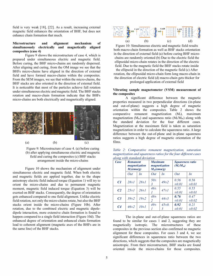
field is very weak [18], [22]. As a result, increasing external magnetic field enhances the orientation of BHF, but does not enhance chain formation that much. Microstructure and alignment mechanism of simultaneously electrically and magnetically aligned composites (case 4) Figure 9 shows the microstructure of case 4, which is prepared under simultaneous electric and magnetic field. Before curing, the BHF micro-chains are randomly dispersed. After aligning and curing, from the OM image we see that the BHFs micro-chains have aligned in the direction of external field and have formed macro-chains within the composites. From the SEM images, we see that within the micro-chains, the BHF stacks are also oriented in the direction of external field. It is noticeable that most of the particles achieve full rotation under simultaneous electric and magnetic field. The BHF stacks rotation and macro-chain formation indicate that the BHFs micro-chains are both electrically and magnetically aligned.
(a) (b) (c)
Figure 9: Microstructure of case 4. (a) before curing (b) after applying simultaneous electric and magnetic
field and curing the composites (c) BHF stacks arrangement inside the micro-chains
Figure 10 shows the mechanism of alignment under simultaneous electric and magnetic field. When both electric and magnetic fields are applied together, due to the shape anisotropy electric field induced torque (Equation 1) will try to orient the micro-chains and due to permanent magnetic moment, magnetic field induced torque (Equation 3) will be exerted on BHF stacks. Consequently, the degree of orientation gets enhanced compared to one field alignment. Unlike electric field rotation, not only the micro-chains rotate, but also the BHF stacks orient inside the micro-chains (Figure 10b). After rotation, due to the combined electric and magnetic dipole-dipole interaction, more extensive chain formation is found to happen compared to a single field interaction (Figure 10d). The enhanced degree of orientation and enhanced chain formation lead to coherent alignment (magnetic axes of the BHFs are in the same line) of the BHF stacks.
(a) (b) (c) (d)
Figure 10: Simultaneous electric and magnetic field results both macro-chain formation as well as BHF stacks orientation in the direction of external field (a) before curing BHF micro-chains are randomly oriented (b) Due to the electric field the ellipsoidal micro-chain rotates in the direction of the electric field. Due to the magnetic field the BHF stacks rotate inside the ellipsoid in the direction of the magnetic field (c) After
rotation, the ellipsoidal micro-chain form long macro-chain in the direction of electric field (d) macro-chain gets thicker for
prolonged application of external field Vibrating sample magnetometer (VSM) measurement of the composites A significant difference between the magnetic properties measured in two perpendicular directions (in-plane and out-of-plane) suggests a high degree of magnetic orientation within the composites. Table 2 shows the comparative remanent magnetization (Mr), maximum magnetization (Mm) and squareness ratio (Mr/Mm) along with the standard deviation for the four different cases. Magnetization at the maximum field is taken as saturation magnetization in order to calculate the squareness ratio. A large difference between the out-of-plane and in-plane squareness ratios suggests a high degree of magnetic orientation of the films. Table 2: Comparative remanent magnetization, saturation magnetization and squareness ratios for the four different cases along with standard deviation
Case Remanent magnetization Mr(emu/g)
Maximum magnetization Mm(emu/g)
Squareness ratio (Mr/Mm)
Out In Out In Out In
C1 28±1 28±1 50±3 49±2 0.56
±0.01 0.56 ±0.01
C2 25±1 26±1 46±1 47±1 0.55
±0.01 0.55 ±0.01
C3 39±2 19±2 48±2 44±3 0.76
±0.01 0.47 ±0.02
C4 46±2 10±1 49±1
45±0.3
0.92 ±0.01
0.21 ±0.02
The in-plane and out-of-plane squareness ratios are found to be similar for cases 1 and 2, suggesting they are magnetically isotropic. The microstructures of these composites in the previous section also confirmed no magnetic alignment for these composites. For cases 3 and 4, we see significant differences in squareness ratio between the two directions, which suggests that the composites are magnetically anisotropic. From their microstructure, BHF stacks are found oriented inside the micro-chains for those composites.

6
Compared to case 3, case 4 is found to have higher difference in squareness ratio which confirms the high degree of magnetic orientation of this composite observed from the microstructure. CONCLUSION
In this paper, we have electrically and magnetically aligned M-type Barium Hexaferrite (BHF) in polydimithylsiloxane (PDMS) to obtain a magnetoactive elastomer composite with anisotropic magnetic properties depending on the orientation of the BHF. After successfully dispersing BHF particles in PDMS, they are electrically and magnetically aligned in the polymer solution. The OM images of the cured composites confirm parallel chain formation of the BHFs as evidence of electrical alignment. Furthermore, the SEM images illustrate the orientation of the BHF stacks within the micro-chain. Magnetic measurements performed using VSM demonstrated anisotropic magnetic properties for the multi-field aligned composites. The fabricated composites under simultaneous electric and magnetic fields showed 21% improvement in squareness ratio compared to magnetically aligned composites. Applying both fields together enhances the degree of orientation and chain formation, which leads to coherent alignment and improved squareness ratio. Future experiments will investigate fabricating multiferroic composites using BHF and an electroactive polymer, namely P(VDF–TrFE–CTFE) terpolymer. REFERENCES [1] X. Z. Zhang, S. L. Peng, W. J. Wen, and W. H. Li,
“Analysis and fabrication of patterned magnetorheological elastomers,” Smart Mater. Struct., vol. 17, no. 4, p. 45001, 2008.
[2] P. von Lockette and C. Breznak, “Evolution of the magnetization response of magneto-active elastomers made with hard-magnetic M-type barium hexaferrite particles,” MRS Adv., vol. 1, no. May, pp. 39–43, 2016.
[3] M. Kallio, T. Lindroos, S. Aalto, E. Järvinen, T. Kärnä, and T. Meinander, “Dynamic compression testing of a tunable spring element consisting of a magnetorheological elastomer,” Smart Mater. Struct., vol. 16, no. 2, pp. 506–514, 2007.
[4] M. Farshad and A. Benine, “Magnetoactive elastomer composites,” Polym. Test., vol. 23, no. 3, pp. 347–353, 2004.
[5] J.-H. Koo, A. Dawson, and H.-J. Jung, “Characterization of actuation properties of magnetorheological elastomers with embedded hard magnetic particles,” J. Intell. Mater. Syst. Struct., vol. 23, no. 9, pp. 1049–1054, 2012.
[6] D. Lisjak and S. Ovtar, “The Alignment of Barium Ferrite Nanoparticles from Their Suspensions in Electric and Magnetic Fields,” 2013.
[7] R. Pethig, “Dielectrophoresis: Status of the theory, technology, and applications,” Biomicrofluidics, vol. 4,
no. 2, p. 22811, 2010. [8] C. P. Bowen, R. E. Newnham, and C. A. Randall,
“Dielectric properties of dielectrophoretically assembled particulate-polymer composites,” J. Mater. Res., vol. 13, no. 1, pp. 205–210, Jan. 1998.
[9] M.-W. Wang, “High density plasma enhanced chemical vapor deposition of optical thin films,” Eur. Phys. J. Appl. Phys., vol. 28, pp. 265–291, 2004.
[10] C. Park, Z. Ounaies, K. A. Watson, R. E. Crooks, J. Smith, S. E. Lowther, J. W. Connell, E. J. Siochi, J. S. Harrison, and T. L. St Clair, “Dispersion of single wall carbon nanotubes by in situ polymerization under sonication,” Chem. Phys. Lett., vol. 364, no. 3–4, pp. 303–308, 2002.
[11] D. A. Van Den Ende, S. E. Van Kempen, X. Wu, W. A. Groen, C. A. Randall, and S. Van Der Zwaag, “Dielectrophoretically structured piezoelectric composites with high aspect ratio piezoelectric particles inclusions,” J. Appl. Phys., vol. 111, no. 12, pp. 0–13, 2012.
[12] D. A. Van Den Ende, B. F. Bory, W. A. Groen, and S. Van Der Zwaag, “Improving the d33 and g33 properties of 0-3 piezoelectric composites by dielectrophoresis,” J. Appl. Phys., vol. 107, no. 2, pp. 0–8, 2010.
[13] D. a. van den Ende, B. F. Bory, W. a. Groen, and S. van der Zwaag, “Properties of Quasi 1-3 Piezoelectric PZT-epoxy Composites Obtained by Dielectrophoresis,” Composites, vol. 114, no. 1, pp. 108–118, 2010.
[14] N. K. James, D. B. Deutz, R. K. Bose, S. van der Zwaag, and P. Groen, “High Piezoelectric Voltage Coefficient in Structured Lead-Free (K,Na,Li)NbO 3 Particulate-Epoxy Composites,” J. Am. Ceram. Soc., vol. 7, no. 38016, pp. 1–7, 2016.
[15] M. A. Al Masud, N. D’Souza, P. von Lockette, and Z. Ounaies, “On the Dielectrophoretic and Magnetic Alignment of Magnetoactive Barium Hexaferrite-PDMS Nanocomposites,” 2017, p. V001T01A015.
[16] M. A. Al Masud, C. Breznak, P. Von Lockette, and Z. Ounaies, “On the electric and magnetic alignment of magnetoactive barium hexaferrite-PDMS composites,” vol. 10165, p. 1016513, 2017.
[17] R. J. Green, K. K. Mallick, P. Shepherd, and R. J. Green, “Dielectric Properties of M-type Barium Hexaferrite Prepared by Co-precipitation Dielectric properties of M-type barium hexaferrite prepared by co-precipitation,” no. December, 2007.
[18] T. B. (Thomas B. Jones, Electromechanics of particles. Cambridge University Press, 1995.
[19] M. A. Al Masud, C. Breznak, P. von Lockette, and Z. Ounaies, “On the electric and magnetic alignment of magnetoactive barium hexaferrite-PDMS composites,” 2017, vol. 10165, p. 1016513.
[20] M. A. Al Masud and Z. Ounaies, “Dielectric Properties of Dielectrophoretically Aligned ZnO-PDMS Composites,” in Volume 1: Multifunctional Materials; Mechanics and Behavior of Active Materials;

7
Integrated System Design and Implementation; Structural Health Monitoring, 2016, p. V001T01A009.
[21] S. Kalidindi, Z. Ounaies, and H. Kaddami, “Toward the preparation of nanocomposites with oriented fillers : electric field-manipulation of cellulose,” vol. 94002.
[22] R. Rosensweig, Ferrohydrodynamics. Cambridge University Press, 1995.