multi-dimensional delay - zikinf
TRANSCRIPT
MULTI-DIMENSIONAL DELAY

2
Introduction .................................................................................................................................................. 3 Precautions.................................................................................................................................................... 3 Rear Panel Connections ............................................................................................................................... 3 Line Drawings and Features........................................................................................................................ 5
Mode Selector............................................................................................................................................ 5 Control Knobs............................................................................................................................................ 5 Footswitches .............................................................................................................................................. 6 LED Indicators .......................................................................................................................................... 7
Delay Modes.................................................................................................................................................. 7 MOD.......................................................................................................................................................... 7 SLAP ......................................................................................................................................................... 9 LONG...................................................................................................................................................... 10 DOTTED EIGHTH ................................................................................................................................. 11 PONG ...................................................................................................................................................... 12 MULTI .................................................................................................................................................... 13 REVERSE ............................................................................................................................................... 14
Preset Operation......................................................................................................................................... 15 Playing Presets......................................................................................................................................... 15 Saving Presets.......................................................................................................................................... 16 Editing Presets ......................................................................................................................................... 16 Restoring Factory Presets ........................................................................................................................ 16
Delay Persist................................................................................................................................................ 17 Delay Modes............................................................................................................................................ 17 Presets...................................................................................................................................................... 17
Strum Tempo .............................................................................................................................................. 18 Looper ......................................................................................................................................................... 19
Recording the main Loop (Track 1)......................................................................................................... 20 Quantized Recording for the main Loop (Track 1).................................................................................. 20 Playing back the main Loop (Track 1) .................................................................................................... 21 Recording more layers (Track 2) ............................................................................................................. 21 Erasing..................................................................................................................................................... 21
MIDI ............................................................................................................................................................ 22 Presets...................................................................................................................................................... 22 Controlling Knob Parameters .................................................................................................................. 22 Footswitch and Encoder Switch Remote Control .................................................................................... 23 Clock Input .............................................................................................................................................. 23
Specifications .............................................................................................................................................. 23 Warranty Information ............................................................................................................................... 24

3
Introduction Congratulations on your purchase of a TimeLine Multi-Dimensional Delay. Our goal is to provide musicians with premium, no-compromise tools that inspire musical performance and creativity. We believe you will find our products to be of lasting value. TimeLine is the world’s finest and most versatile delay product. 96KHz processing buffered by dual 12AX7’s produces un-compromised signal quality of the processed sound, while the analog dry path ensures transparency. From vibrato, phasing, flanging and chorus, to slap-back, long echoes, multi-head and reverse, the TimeLine’s continuous controls let you create your sound simply by turning knobs. The user presets, tap tempo, strum tempo, 2-track looping, and MIDI implementation make sure the TimeLine delivers in any performance or studio application.
Precautions
The TimeLine’s tube circuits run at very high internal voltages. Never remove the back panel of the unit. There are no user serviceable parts inside.
Use only with the supplied AC power adapter. Avoid spilling liquids into the unit. Do not expose the unit to excessive heat or moisture. Refer all service and repairs to a qualified technician. Unplug unit when not is use.
Rear Panel Connections Audio I/O Jacks
Delay effects are typically placed after distortion effects, or in the effects loop of an amplifier if available.
The TimeLine is a true stereo processor. The Left and Right inputs are processed independently and sent to the Left and Right outputs respectively. With a mono input, a stereo output is produced when using both outputs. The TimeLine can be used in three basic I/O configurations:
!
INPUT L (MONO) INPUT R OUTPUT L
(MONO)OUTPUT R
MIDI IN MIDI OUT
POWER

4
Mono-In/Mono-Out Mono-In Mono In-Stereo Out Stereo In-Stereo Out MIDI Connections Connecting the output of a MIDI controller unit to the MIDI IN jack of the TimeLine allows you to sync to clock, to control the knobs and switches remotely, and to access an almost unlimited number of Preset Locations. Connect the MIDI Out to the MIDI In of another MIDI device. MIDI messages sent to TimeLine will be echoed to the MIIDI Out jack. For more on MIDI, see the section under MIDI. Power Jack Use only the included Damage Control power supply to power the TimeLine.

5
Line Drawings and Features
Mode Selector This twelve-position encoder determines the operational mode of the TimeLine, selecting one of seven Delay modes (MOD, SLAP, LONG, DOTTED_EIGHTH, PONG, MULTI, and REVERSE), Looper mode, or one of four Preset Banks. The encoder has a push-switch that is used during preset saving, and loop erasing. See the sections on Preset Operation and Looper for more detail. Control Knobs Note: For knob operation in LOOP mode, see the section under LOOPING.
TIME – sets the delay time based on the Mode setting.
REPEATS – sets the number of repeats from one at minimum to infinity at maximum. In MOD mode (Delay Times from 1ms to 25mS) this control is commonly called Regeneration, and will intensify any sound as it is turned clockwise.
!
Control Knobs
Mode Selector
Footswitches
LED Indicators
Magic Eye
BYPASS TAP TEMPO
Left Tube Chamber
Right Tube Chamber

6
MOD DEPTH – sets the range of modulation from no modulation at OFF, to full modulation at maximum. In MULTI mode, Mod Depth controls the position of playback head 1, from no delay (OFF) to max delay determined by the current delay time.
MOD SPEED – controls the speed of the modulation from .1 Hz to 10 Hz. In MULTI mode, Mod Depth controls the position of playback head 2, from no delay (OFF) to max delay determined by the current delay time.
FILTER – sets the filter shape of the repeat filter from flat (no filter) at OFF to an analog-stomp-type shape at 12:00 to a tape-type filter at maximum. The filter morphs smoothly between these points.
SMEAR – smoothes out percussive or sharp attacks over time, creating repeats that don’t interfere with the direct signal. At minimum setting this effect is off, and gradually increases to maximum effect.
MIX – sets the ratio of dry signal to wet signal, from fully dry at minimum, to fully wet at maximum. The Grit and Filter controls may affect the relative level of the delayed signal, so you may want to fine tune the Mix and Repeats control once you dial in the delay sound you want.
GRIT – adds gradual amounts of distortion, noise and even some aliasing reminiscent of analog bucket-brigade circuits with low clock-speeds.
Footswitches
BYPASS LOOP:START/STOP
In the Delay modes this footswitch toggles between BYPASS and effect ON. In any Preset Bank, step on this switch to toggle between Preset A and Bypass. In Looper Mode this activates RECORD start and stop, and subsequently acts as PLAYBACK start and stop. For more information, see the sections on Preset Operation and Looper.
TAP TEMPO LOOP:PUNCH IN/OUT
In the Delay modes, step at the desired delay time to set the delay tempo. BONUS: In these modes you can also hold down the button and pluck or strum staccato notes to set the tempo. In any Preset Bank, step on this switch to toggle between Preset B and Bypass. In Looper Mode, press and hold this to record Track 2. For more information, see the sections on Preset Operation and Looper.
A
B

7
LED Indicators The LED indicators offer a comprehensive survey of the state of operation of TimeLine. For detailed information on the LED indicators in each mode, see the individual sections under Delay Modes, Preset Operation, and Looper.
LEFT TUBE CHAMBER – indicates the MOD SPEED and MOD DEPTH settings in the Delay modes. In Preset Operation, this indicates the ON/BYPASS status of Preset A. In Looper mode, the status of Track 1 is indicated.
RIGHT TUBE CHAMBER – indicates the Delay Time in the Delay modes. In Preset Operation, this indicates the ON/BYPASS status of Preset B. In Looper mode, the status of Track 2 is indicated.
MAGIC EYE – indicates the Delay Time in the Delay modes. In Preset Operation, this indicates the Delay Time of an engaged preset. In Looper mode, the Magic Eye displays Loop Tempo and/or loop status.
Delay Modes TimeLine’s seven Delay Modes, in conjunction with the eight continuous controls, allow you to re-create the sounds of classics from vintage to modern, including tape based units, vintage stomps, and studio rack processors. But TimeLine isn’t limited to what has been done in the past. Use your imagination along with the power and flexibility of the continuous controls to create sounds that are uniquely your own. MOD
The delay ranges from 1ms to 25ms in MOD mode. These ultra-short delays create EQ effects such as comb filtering and resonators when the delay time is fixed. Phasing, vibrato, flanging and chorus effects are obtained when the delay time is modulated with the Mod Depth and Mod Speed controls.
LED Indicators In Mod Mode, all LED indicators display the Mod Speed and Mod Depth settings. With Depth at minimum (no modulation) the LEDs are orange. As Depth increases, the LEDs change from orange to red to green at the Speed of the LFO, with the intensity of the change increasing with the Depth control. When BYPASSED, the tube chambers and Magic Eye are green.
Tap Tempo
Step on the TAP TEMPO button at the rate you want for modulation speed (otherwise set by the MOD SPEED knob). Alternatively, you can step and hold the TAP TEMPO button down while you play or strum staccato notes to set the modulation speed.

8
Tips • The Repeats control is commonly called Regeneration or Feedback when delay times are in
this ultra-short range. Turning the Repeats knob clockwise will intensify any sound, making a resonant filter more peaky, or a flanger sound more jet-like, or a chorus more de-tuned.
• The Mod Speed and Mod Depth work together to vary the Delay Time. If turning up the Mod
Speed control results in unwanted increases in pitch variations, then the Mod Depth can be reduced to compensate.
• Use the Filter and Grit controls to shape the fidelity of the sound. The Smear control will add
a larger spatial dimension to the sound when turned up.
Example Settings Filter/Resonator
Vary the Delay Time knob to see how this affects the tuning of the resonator. The intensity of the effect is varied with the Repeats (Regeneration). Make sure the Mix is at 12:00 for maximum effectiveness
Comb Phaser Similar to the Resonator, but now the Mod Speed and Mod Depth vary the Delay Time. Again, the Repeats control sets the intensity of the effect. Leslie (Doppler) One of the characteristic sounds of a rotating speaker is the pitch variation that occurs as a result of the motion of the speaker, known as the Doppler effect. Set Mix to full Wet to hear the pitch variations without interaction with the Dry signal. This setting uses the Filter to add some character. Tape Flanger Slightly longer Delay Time, lots of Regeneration, and a 50/50 Dry/Wet Mix creates a flanging effect. Add some Filtering to create a warm tape-driven flanger. Vary the Delay Time knob to ‘tune’ the flanger’s voice.
Digital Chorus Increasing the Delay Time and eliminating the regeneration (Repeats) yields a chorus. By turning off the Filter, we get a clean high-bandwidth effect. The Smear control adds dimension to the sound.

9
SLAP
In SLAP mode, the delay time ranges from 25ms to 250ms, creating short delays suitable for slap-back, rockabilly, surf, and sci-fi, as well as subtle delays to add some ambience to lead or rhythm parts in a variety of styles.
LED Indicators In SLAP Mode, the Left Tube Chamber indicates the modulation settings, changing from green to red at the MOD SPEED rate, with intensity determined by the MOD DEPTH. The Magic Eye and Right Tube Chamber flash red to indicate the delay time. When BYPASSED, the tube chambers are green and the Magic Eye flashes green at the delay rate.
Tap Tempo
Step on the TAP TEMPO button at ¼ note intervals. The TimeLine will set the delay time to 1/16 note intervals to allow you to accurately set short delay times. Alternatively, you can step and hold the TAP TEMPO button down while you play or strum staccato notes (at ¼ note tempo) to set the delay time.
Tips • The short delay times of Slap mode make for great runaway delays when the REPEATS
control is at maximum. If the delay sound gets too loud, adjust the MIX level appropriately. • Add a little modulation to slap-back delays to add some dimension and a bit of realistic wow
and flutter to the sound. • Experiment with the GRIT and FILTER controls to change the fidelity of the repeats. Example Settings Tape-Style Slap The Filter control sets up this sound with the characteristics found in old tape units. Experiment with the Smear knob to add more dimension to the slap sound.
Vintage Stomp Echo The bucket brigade circuits found in analog stomp boxes add noise, distortion, and even aliasing from low clock speeds. The Grit control adds all of these elements to the repeats as well. Adjust Mix and Repeats as needed when dialing in the Grit control. Springy A delay of about 60 ms with lots of repeats provides a spring reverb simulation. Listen to what happens when the TimeLine’s Filter and Smear control are put into action. The spring comes to life with a realistic tank tonality and added dimensionality. Sci-Fi Adjust the Repeats to dial in the run-away nature of the sound. With Repeats at maximum, play with the Delay Time knob to get really spacey. If the delay sound gets too loud, adjust the MIX level appropriately.
10
LONG
Long mode produces delay times from 250ms to 2.5s. These long echoes can accentuate solos or create dramatic space and atmospheric textures for chordal work.
LED Indicators In LONG Mode, the Left Tube Chamber indicates the modulation settings, changing from green to red at the MOD SPEED rate, with intensity determined by the MOD DEPTH. The Magic Eye and Right Tube Chamber flash red to indicate the delay time. When BYPASSED, the tube chambers are green and the Magic Eye flashes green at the delay rate. Tap Tempo Step on the TAP TEMPO button at the desired rate to set the delay time. Alternatively, you can step and hold the TAP TEMPO button down while you play or strum staccato notes to set the delay time. Tips • The SMEAR control will soften the percussive attacks on repeats, allowing you to create
delays with higher MIX or REPEATS setting without interfering with the direct signal as much.
• The FILTER, GRIT, and SMEAR controls work progressively on each repeat, so that delays
with the REPEATS control turned up can morph into dense, ethereal sounds.
• Add some slow moving modulation to long delays to add beautiful stereo imaging to chordal work.
Example Settings
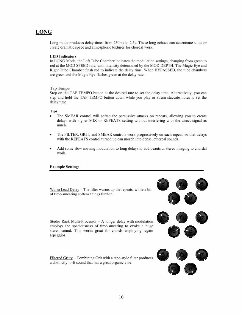
Warm Lead Delay – The filter warms up the repeats, while a bit of time-smearing softens things further. Studio Rack Multi-Processor – A longer delay with modulation employs the spaciousness of time-smearing to evoke a huge stereo sound. This works great for chords employing legato arpeggios. Filtered Gritty – Combining Grit with a tape-style filter produces a distinctly lo-fi sound that has a great organic vibe.

11
DOTTED EIGHTH
The DOTTED EIGHTH mode produces delay times equal to ¾ of the tempo entered by Tap Tempo or Strum Tempo. So tapping in quarter notes sets the delay time to dotted-eighth notes. This makes it easy to achieve synchronized syncopated rhythm and single note passages. The DELAY TIME knob will vary the delay time from 250ms to 2.5 seconds in dotted eighth mode.
LED Indicators In DOTTED-EIGHTH Mode, the Left Tube Chamber indicates the modulation settings, changing from green to red at the MOD SPEED rate, with intensity determined by the MOD DEPTH. The Magic Eye and Right Tube Chamber flash red at the quarter note tempo. When BYPASSED, the tube chambers are green and the Magic Eye flashes green at the quarter note tempo. Tap Tempo As mentioned, tap quarter notes to set the delay time to dotted eighth notes. Alternatively, you can step and hold the TAP TEMPO button down while you play or strum staccato quarter notes to set the delay time to dotted-eighth notes. Tips • For maximum rhythmic effect, set the Mix near 50% and turn MOD DEPTH, FILTER,
SMEAR and GRIT to minimum (off).
Example Settings Brick Wall – For precise setting of the Delay Time, use the Tap Tempo or Strum Tempo feature to set the ¼ note tempo.

12
PONG
The stereo effect of having the repeats alternate between left and right channels is commonly referred to as a ‘ping pong delay’. In mono mode, this will sound like a regular delay running at twice the speed indicated by the Magic Eye. The DELAY TIME knob will produce delays ranging from 250ms to 2.5s, with alternating left and right channel delays occurring during the delay time. LED Indicators In PONG Mode, the Left Tube Chamber indicates the modulation settings, changing from green to red at the MOD SPEED rate, with intensity determined by the MOD DEPTH. The Magic Eye and Right Tube Chamber alternately flash red at the delay time interval to indicate the ping-pong action. When BYPASSED, the tube chambers are green and the Magic Eye flashes green at the overall delay rate. Tap Tempo Tap tempo sets the overall delay time for PONG mode. TimeLine will produce two outputs (one left and one right) per tapped interval. Step on the TAP TEMPO button at the desired rate to set the delay interval. Alternatively, you can step and hold the TAP TEMPO button down while you play or strum staccato notes to set the overall delay time.
Tips • PONG mode will create huge stereo imaging with smaller DELAY TIME settings when
REPEATS, SMEAR, and MOD controls are turned up
• For a ‘center – left – right only once’ delay, turn REPEATS to minimum. Example Settings
Long Pong – A little modulation adds some flavor to this delay.
Short and Spacious – The Smear, Grit and Filter controls serve to obscure the individual repeats and create a dense stereo sound like a synth-pad when used with sustained chords.
13
MULTI
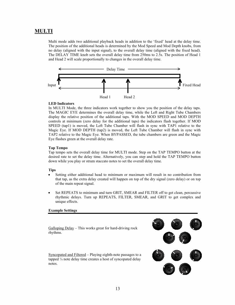
Multi mode adds two additional playback heads in addition to the ‘fixed’ head at the delay time. The position of the additional heads is determined by the Mod Speed and Mod Depth knobs, from no delay (aligned with the input signal), to the overall delay time (aligned with the fixed head). The DELAY TIME knob sets the overall delay time from 250ms to 2.5s. The position of Head 1 and Head 2 will scale proportionally to changes in the overall delay time.
LED Indicators In MULTI Mode, the three indicators work together to show you the position of the delay taps. The MAGIC EYE determines the overall delay time, while the Left and Right Tube Chambers display the relative position of the additional taps. With the MOD SPEED and MOD DEPTH controls at minimum (zero delay for the additional taps) the indicators flash together. If MOD SPEED (tap1) is moved, the Left Tube Chamber will flash in sync with TAP1 relative to the Magic Eye. If MOD DEPTH (tap2) is moved, the Left Tube Chamber will flash in sync with TAP2 relative to the Magic Eye. When BYPASSED, the tube chambers are green and the Magic Eye flashes green at the overall delay rate. Tap Tempo Tap tempo sets the overall delay time for MULTI mode. Step on the TAP TEMPO button at the desired rate to set the delay time. Alternatively, you can step and hold the TAP TEMPO button down while you play or strum staccato notes to set the overall delay time. Tips • Setting either additional head to minimum or maximum will result in no contribution from
that tap, as the extra delay created will happen on top of the dry signal (zero delay) or on top of the main repeat signal.
• Set REPEATS to minimum and turn GRIT, SMEAR and FILTER off to get clean, percussive
rhythmic delays. Turn up REPEATS, FILTER, SMEAR, and GRIT to get complex and unique effects.
Example Settings
Galloping Delay – This works great for hard-driving rock rhythms. Syncopated and Filtered – Playing eighth-note passages to a tapped ¼ note delay time creates a host of syncopated delay notes.
Input Fixed Head
Delay Time
Head 1 Head 2

14
REVERSE
TimeLine’s Reverse mode is ‘triggered’, meaning it will align itself with your playing to give you a predictable and repeatable performance. Max delay time in Reverse is a full 2.5 seconds. NOTE: The MOD SPEED and MOD DEPTH controls will not affect the first reverse sound, but will work on subsequent repeats when the REPEATS control is turned up.
LED Indicators In REVERSE Mode, the Left Tube Chamber indicates the modulation settings, changing from green to red at the MOD SPEED rate, with intensity determined by the MOD DEPTH. The Magic Eye and Right Tube Chamber flash red to indicate the delay time. When BYPASSED, the tube chambers are green and the Magic Eye flashes green at the delay rate.
Tap Tempo Step on the TAP TEMPO button at the desired rate to set the delay time. Alternatively, you can step and hold the TAP TEMPO button down while you play or strum staccato notes to set the delay time. Tips • When you start playing, the reverse mode will align itself (triggers) to give smooth and
repeatable response to your playing. Once triggered, the delay will hold off from re-triggering until two delay-time intervals have passed. This allows you to play a phrase for the duration of the delay time, and hear it replay backwards before it will realign to you next phrase. Play cleanly and deliberately at the start of your phrases for precise repeatable results.
• Try playing sustained chords with short reverse delay times. Let the chords ring for several
delay intervals before playing another chord. Each chord will trigger the delay to provide a unique rhythmic effect.
Example Settings Psychedelic Lead – It’s digital LSD.
Reverse Envelope Chords – A unique sound that’s effective for strummed chords. Use Tap Temp or Strum Tempo to sync up the delay with your song tempo.

15
Preset Operation The TimeLine can store eight presets (2 available in each of the four Preset Banks) without any external MIDI connection. With MIDI, there is access to hundreds of locations. See the section under MIDI for more information. Playing Presets
With the encoder in one of the Preset Bank positions, the TimeLine can access two preset sounds (A or B) or be Bypassed, so you can set up a sound for rhythm and a different sound for lead for example, as well as bypass the delay altogether. The footswitch operation allows one-step access for all switching combinations.
The following chart shows the LED indicator states during Preset playback:
Left Tube Chamber(A) Right Tube Chamber(B) Magic Eye Preset A active RED GREEN Flashes RED at Delay Time of A 1
Preset B active GREEN RED Flashes RED at Delay Time of B 1 Bypass GREEN GREEN GREEN
1. For presets saved from MOD Mode the Magic Eye displays the modulation settings as described in the Mod section under Delay Modes.
_____________________________________________________________________________________ To activate a preset:
1. Turn the encoder to one of the Preset Banks
2. If one tube chamber is red, the corresponding preset is active. Stepping on the other footswitch will activate that preset directly.
3. If the unit is in BYPASS (all indicators green), step on either the A or B footswitch to activate the corresponding preset
4. Stepping on the active preset’s footswitch again will put the unit in BYPASS

16
Saving Presets
The knob positions and Delay Mode setting can be saved for any of the seven Delay Modes. LOOP mode and loop data cannot be saved.
Once you have a sound that you want to save:
1. PUSH AND RELEASE the encoder knob. The Magic Eye will turn green and the tube chambers will turn orange to acknowledge the initiation of Preset Save.
2. Turn the Encoder to the Preset Position that you want to store it to.
3. To save the settings to A, step on the A footswitch. To save the settings to B, step on the B footswitch. The tube chamber of the selected preset will turn red, and the Magic Eye will indicate the delay time (or MOD settings) of the newly written preset.
If steps 2 and 3 aren’t completed within 10 seconds of pushing the encoder knob, the process will abort and the TimeLine will resume operation based on the current positions of all parameter knobs and the selected mode.
Note: Once a preset is written to a location, the previous Preset at that location is lost.
Editing Presets
When playing a preset, all parameter knobs are available for adjustment. So if you are playing a preset and want to change the Mix parameter, just turn the Mix knob to the new desired value. All other parameters will remain unchanged, unless their corresponding knob is adjusted. If you like your adjustments and want to save the new sound, you simply save the new sound exactly as you would if you were writing a new preset. For example, you can overwrite the current preset by pushing and releasing the encoder, then stepping on the same footswitch that the current preset is saved to. To write your edited preset to a new location without changing the original, push and release the encoder and then select the new location with the encoder and footswitches as described above.
Note: Once a preset is written to a location, the previous Preset at that location is lost.
Restoring Factory Presets
TimeLine comes with eight factory presets that can be restored by the following procedure: 1. Disconnect the power adapter plug from the power jack 2. Press the encoder 3. Connect the power adapter plug to the power jack while continuing to press the encoder for 5 seconds. Note that this will overwrite all eight presets. MIDI presets from program change 9 and up will not be affected. See the section on MIDI for more information.

17
Delay Persist
TimeLine can continue to process the delay signal after you step on the Bypass switch, allowing for natural decay of the repeated signal when the TimeLine is Bypassed. Delay Modes The state of Delay Persist is global when TimeLine is in Delay Mode, i.e. when Delay Persist is activated in one of the seven Delay Modes, it remains activated for all of the Delay Modes. To activate Delay Persist: (with the Mode Selector in any Delay Mode)
1. PUSH AND HOLD DOWN the Mode Selector. 2. PRESS AND RELEASE the ON/BYPASS footswitch 3. RELEASE the Mode Selector.
To exit Delay Persist mode, follow the same procedure that was used to enter Delay Persist mode.
Note: TimeLine will remember the most recent global state of Delay Persist upon power up.
Presets In Preset operation, the Delay Persist state is saved individually for each preset location, so you can save some presets with it on, and some with it off. To Save a new Preset (from one of the seven Delay Modes) with Delay Persist active:
1. Activate Delay Persist as described above 2. Save the preset as described under Saving Presets
You can also change the Delay Persist state of an existing preset. This has no effect on the global Delay Persist state of the Delay Modes. To change the Delay Persist state of an existing preset: 1. Set the TimeLine so the desired Preset is active (its Tube Chamber is Red)
2. PUSH AND HOLD DOWN the Mode Selector. 3. PRESS AND RELEASE the footswitch of the preset you are changing. 4. RELEASE the Mode Selector.
At this point the preset will respond to the change in Delay Persist when it is Bypassed, but the preset has not been saved with the change yet. If you access another preset or move the Encoder knob, the change will be lost. In order to save the Delay Persist change, the preset needs to be saved as described under Editing Presets
!

18
Strum Tempo You can adjust the Delay Time (or Mod Speed in Mod mode) based on strumming input from your guitar, giving you another way to take advantage of TimeLine’s power in live situations.
To set the Delay Time based on strum input: 1. PRESS AND HOLD the TAP TEMPO footswitch
2. Strum or pluck staccato notes at the ¼ note tempo you desire. The Magic Eye and Right Tube chamber will flash red to acknowledge each input. Timeline will respond to ¼ note strums in the same manner as if the footswitch had been tapped at the same tempo. 3. RELEASE the TAP TEMPO footswitch.
Tips
• Be precise with your playing during strum tempo input. • Try to leave space between the quarter-notes – play staccato • If you are playing with high gain, or a very noisy guitar signal and the strums are not being
recognized by TimeLine (Magic Eye and Right Tube Chamber not flashing), turn down your guitar’s volume control a bit and try again.

19
Looper In LOOP mode, the TimeLine becomes a 2-track looping recorder with twenty seconds of available record time per track. Track 1 serves as the main loop, setting the overall loop time. Track 2 adds an infinite-overdub layer on top of Track 1. Both tracks have individual PAN and LEVEL control. The knob functions in LOOP mode are shown below: The switches are shown below:
LED Indicators The Left Tube Chambers indicates the status of Track 1, and the Right Tube Chamber indicates the status of Track2. Green indicates an empty track, orange indicates recorded audio, and red indicates recording in progress. The Magic Eye is orange in Loop Mode during recording and playback and will flash at the quantize interval if quantized looping is active. When the loop is stopped, the Magic Eye is red.
Click Volume
Click Tone
Loop ERASE (push) DIRECT/LOOP MIX
Track 1 Playback Level
Track 1 Playback Pan
Start / Stop Track 1 RECORD
TAP TEMPO Track 2 RECORD
Track 2 Playback Level
Track 2 Playback Pan
Click Select

20
Recording the main Loop (Track 1)
NOTE: Set the MIX control to 12:00 to monitor your playing during recording. Set the Track 1 Level control to maximum and the Track 1 Pan control to 12:00 to monitor the sound initially during playback once the track is recorded.
1. Turn the Mode Selector to LOOP. The tube chambers will all turn green to indicate that no loop data is present. The Magic Eye will be orange.
2. Once you’re ready to play, press and release the LOOP:START / STOP button. The Left Tube Chamber turns red and Track 1 begins recording immediately.
3. To stop recording, press and release the LOOP:START / STOP button. The Left Tube Chamber turns orange and Track 1 begins playing back immediately.
Quantized Recording for the main Loop (Track 1)
NOTE: Set the MIX control to 12:00 to monitor your playing during recording. Set the Track 1 Level control to maximum and the Track 1 Pan control to 12:00 to monitor the sound initially during playback once the track is recorded.
The loop length can be quantized to tempo input through the TAP TEMPO footswitch, or from MIDI clock. See the section under MIDI for more information.
The loop-quantizing interval can only be set when there is no loop data present (indicated by green Left and Right Tube Chambers). To erase the loop data, press the encoder until both Tube Chambers turn green. See Loop Erasing for more details.
1. Using the TAP TEMPO footswitch, tap in the desired quantization period. A click is generated indicating the quantizing window boundaries, and the Magic Eye will flash orange at the quantizing boundaries. You can also enter quantization with Strum Tempo by holding down the TAP TEMPO switch and playing staccato notes at the desired tempo.
2. Use the Click Select to choose one of four click samples (sticks, claves, cowbell, and hi-hat). Adjust the Click Tone and Click Volume knobs to your preference.
3. Once you’re ready to play, press and release the LOOP:START / STOP button. Track 1 begins recording at the next occurring click event indicated by the Left Tube chamber turning red.
4. To stop recording, press and release the LOOP:START / STOP button in the last quantizing interval of the loop. The loop will continue recording until the end of the interval, at which time playback begins.
Once recording has stopped, the click signal goes away.
NOTE: Loop Tempo cannot be changed once a loop has been recorded.
!
!
!
21
Playing back the main Loop (Track 1)
Set the Track 1 Level control to maximum and the Track 1 Pan control to 12:00 to monitor the sound initially. Playback starts immediately after Track 1 is recorded. To stop playback:
Push and release the LOOP:START / STOP button. The Magic Eye will turn red to indicate Loop playback stopped
To start playback:
Push and release the LOOP:START / STOP button. Track 1 begins playing immediately. The Magic Eye will turn orange to indicate Loop playback in progress.
Adjust the Track 1 Level and Track 1 Pan controls to the desired settings.
Recording more layers (Track 2)
Set the MIX control to 12:00 to monitor your playing during recording. Set the Track 2 Level control to maximum and the Track 1 Pan control to 12:00 to monitor the sound initially
To record on Track 2:
1. Start Track 1 playback as noted above.
2. Push and release the LOOP PUNCH IN/OUT button. Track 2 begins recording immediately.
To stop recording on Track 2:
Push and release LOOP PUNCH IN/OUT button.
You can punch in and out over the entire length of the loop. If you punch in over previously recorded material on Track 2, the original Track 2 audio will be mixed with the newly recorded audio, allowing for infinite overdub capabilities. As the loop plays back, you will hear the Track 2 audio mixed with the Track 1 main loop. Use the Track 2 level and Pan controls to adjust the sound as you desire.
Erasing
If only Track 1 contains data (Left Chamber Orange, Right Chamber green): Push the Mode Selector once to erase Track 1. The Left Tube Chamber will turn green. At this point, a new quantizing interval can be input with the TAP TEMPO footswitch if desired.
If both tracks contain data (indicated when both Tube Chambers are orange) : Press the Mode Selector once to erase the Track 2 data (Right Tube Chamber turns green) and leave the Track 1 main loop intact. Press the Mode Selector again to erase Track 1 (Left Tube Chamber turns green). Now all loop data is erased.
NOTE: Loop data cannot be saved. Loop data is erased once the Mode Selector is changed to another position.
!

22
MIDI TimeLine allows access to 1280 presets, full remote control of all knobs and switches, and advanced control, such as clock input. TimeLine responds to MIDI messages sent on MIDI Channel 1. Presets
• Presets are organized as 10 banks of 128 presets, for a total of 1280 presets. • TimeLine will respond to standard MIDI Program Change Message. • The default Bank is Bank 0 (when no MIDI Bank message is sent). • Bank messages are sent with controller 00, with values ranging from 0 to 9. • MIDI presets 1-8 correspond to the eight presets that are accessible from the top panel controls of
TimeLine. • TimeLine responds to messages sent on MIDI Channel 1.
To write a preset to a MIDI location: 1. Set the knobs to get the sound you want 2. Press and release the encoder
3. Send a program change message on MIDI Channel 1 to the MIDI location you want to save the settings to. For Locations greater than 128, send a Bank Message on Controller 00, followed by a program change message.
When TimeLine receives a Program Change message, the Footswitches act as if the unit is in Delay mode, i.e. you can Bypass TimeLine with the ON/BYPASS footswitch, and you can input new tempo information with the TAP TEMPO footswitch when presets are selected through MIDI program change. Controlling Knob Parameters The following table shows the MIDI controllers that correspond to the knobs of TimeLine. TimeLine responds to messages sent on MIDI Channel 1. FUNCTION CONTROLLER VALUE RANGE ENCODER POSITION 10 (0x0A) 0 - 7 GRIT 16 (0x10) 0-127 MIX 17 (0x11) 0-127 MOD SPEED 18 (0x12) 0-127 MOD DEPTH 19 (0x13) 0-127 TIME 20 (0x14) 0-127 REPEATS 21 (0x15) 0-127 FILTER 22 (0x16) 0-127 SMEAR 23 (0x17) 0-127
!

23
Footswitch and Encoder Switch Remote Control The Footswitches and Encoder Switch are controlled by MIDI NOTE messages. Switches are pressed with a NOTE ON message and released with a NOTE OFF message. A NOTE OFF message can also be achieved with a NOTE ON message with a velocity of 0. TimeLine responds to messages sent on MIDI Channel 1. FUNCTION NOTE ON/BYPASS D0 (0x1A) TAP TEMPO C0 (0x18) ENCODER SWITCH E0 (0x1C) Clock Input The TimeLine responds to standard (0xF8) MIDI clock messages.
Specifications Nominal Input Impedance…………………………………………….…1 Meg ohm Nominal Output Impedance…………………………………………….. 100 ohm Dynamic Range Dry Path……………………………………………… 123dB (A-weighted) Dynamic Range Wet Path………………………………………………. 110dB (A-weighted) Processing…………………………………..…………………………... 32 Bit floating point, 96KHz Maximum Output Signal……………………………………………….. +12DBv Power Requirements……………………………………………………. 9vac 2000mA Dimensions…………………………………………………….……….. 9 x 7.3 x 3.3 inches Weight………………………………………………………….……….. 3.8 lbs

24
Warranty Information Your TimeLine is warranted to be free of defects in materials and workmanship for a period of one year from the date of purchase. The tubes are warranted for a period of 90 days from the date of purchase. If you need to return your unit for warranty repair, please contact Damage Control through our website, www.damagecontrolusa.com, for Return Authorization and information.
DAMAGE CONTROL NON-TRANSFERABLE LIMITED WARRANTY Keep this document in a safe place
Customer Name _______________________________________ Date of Purchase _______________________________________ Purchased from ________________________________________ Serial Number _________________________________________
WARRANTY Damage Control Engineering, LLC warrants the product to be free from defects in material and workmanship for a period of one (1) year from the original date of purchase. The tubes are warranted for a period of ninety (90) days from the original date of purchase. If the product fails within the warranty period, Damage Control Engineering, LLC will repair or, at our discretion, replace the product at no cost to the original purchaser. EXCLUSIONS This warranty covers defects in manufacturing discovered while using this product as recommended by Damage Control Engineering, LLC. This warranty does not cover loss or theft, nor does the coverage extend to damage caused by misuse, abuse, unauthorized modification, improper storage, lightning, or natural disasters. LIMITS OF LIABILITY In the case of malfunction, the purchaser’s sole recourse shall be repair or replacement, as described in the preceding paragraphs. Damage Control Engineering, LLC will not be held liable to any party for damages that result from the failure of this product. Damages excluded include, but are not limited to, the following: lost profits, lost savings, damage to other equipment, and incidental or consequential damages arising from the use, or inability to use this product. In no event will Damage Control Engineering, LLC be liable for more than the amount of the purchase price, not to exceed the current retail price of the product. Damage Control Engineering, LLC disclaims any other warranties, express or implied. By using the product, the user accepts all terms herein. HOW TO OBTAIN SERVICE UNDER THIS WARRANTY Contact Damage Control through our website at www.damagecontrolusa.com for Return Authorization and information. Proof of original ownership may be required in the form of receipt from an authorized dealer