mueller gas · 2017-06-05 · customer service center decatur, illinois 800.798.3131...
TRANSCRIPT

Customer Service CenterDecatur, Illinois
800.798.3131www.muellergas.com
All warranties, expressed or implied, for Mueller Drilling Machines are rendered null and void if the machines are used with shell cutters or
equipment manufactured by someone other than Mueller Co.
WARNING: 1. Read and follow instructions carefully. Proper training and periodic review regarding the use of this equipment is essential to prevent possible serious injury and/or property damage. The instructions contained herein were developed for using this equipment on fittings of Mueller manufacturer only, and may not be applicable for any other use.2. Do noT exceed the pressure ratings of any components or equipment. Exceeding the rated pressure may result in serious injury and/or property damage.3. Safety goggles and other appropriate protective gear should be used. Failure to do so could result in serious injury.4. Pressure test, check for and repair leaks in all fittings and components each time one is installed or any joint or connection is broken. Failure to find and repair a leak from any source in the fittings, by-pass lines or equipment could result in an explosion and subsequent serious injury and/or property damage.5. MUELLER® Drilling Machines and Equipment have been carefully designed and engineered to work together as a unit. The use of equipment manufactured by someone other than Mueller Co. may cause excessive wear or a malfunction of the MUELLER machines.
!
Reliable ConnectionsTM
Line StopperUnit No. 1TM
MUELLER®
GAS
o p E R At i n G i n S t R U c t i o n S M A n U A L
TAbLE oF ConTEnTS PAGE
INSTALLING AND STOPPING OFF 1” ThrOuGh 21/2” LINE STOPPEr FITTINGS Catalog Numbers: h-17125; h-17126; h-17155; h-17156; h-17160; h-17161; h-17165 and h-17175 2–9
STOPPING OFF 11/2” AND 2” EXTENSION STOPPEr FITTINGS Catalog Number: h-17140; h-17141; h-17150 and h-17151 10
INSTALLING AND STOPPING OFF 11/2” AND 2” EXTENSION STOPPEr FITTINGS Catalog Numbers: h-17142; h-17143; h-17152 and h-17153 11–14
FLOW ChArT 14
NOTES 15

A.
Line Stopper Unit No. 1TM
General Specifications / Instructions for Installing and Stopping-Off 1” – 2 1/2” Line Stopper Fittings
2
Capacity and UseLine Stopper Fittings are often used in pairs to isolate a section of pipe line. For this reason, unit No. 1 consists of Machines and Attachments for stopping-off two Line Stopper Fittings at the same time. Only one Set of Attachments is required for drilling the pipe line since this operation can be done on one Fitting at a time.
Working Pressure and Temperature Rating125psi Maximum Working Pressure 250º F Maximum Temp. rating The line pressure and temperature must not ex ceed these amounts during the use of this Equipment. The line pressure and temperature may be increased to the maximum working pressure and temperature of the Fitting after the Fitting is fully installed with the Completion Plug and Completion Cap in place.
1. Thoroughly clean the pipe where the fitting is to be attached.2. remove the completion cap.3. Loosen the completion plug slightly, but DO NOT remove. Fittings having O-ring seal completion plugs must be loosened to expose the O-ring out of the fitting. Use the completion plug wrench. 4. Place the two halves of the fitting around the pipe. Check to be sure they are in proper alignment.
A–Select Attachments Required1. From the Gas Products Catalog select attachments required according to the size and catalog number of the fitting to be used. See instruction “H” for arrangement of piping.
B–Installing Line Stopper FittingTo Install the H-17125, H-17126, H-17155, H-17156; H-17160 or H-17161 Welding Line Stopper Fittings (Fig. A), follow instruction 1 – 8.
Installation Instructions
Inserting Bar
By-PassConnection
Feed Nut & Yoke
Coupler Sleeve
Collar
H-17135Stopping Machine
Mueller® No-Blo® Operations performed by the Mueller® H-17135 Machine: Item SIze* muellerNo-BlooperatIoN Mueller NO-BLO
Make Stop-Off, Insert or Extract Service Line 11/2” 2” 21/2” Completion Plug
Stopper Fitting
Mueller Low Make Stop-Off, Insert or Extract Pressure Line 2” 3” 4” Completion Plug
Stopper Fitting*The size refers to the nominal size of Mueller Line Stopper Fittings and Low Pressure Line Stopper Fittings.
Required Equipment for Installing and Stopping-off 1”–21/2” Line Stopper Fittings 1 – Mueller® D-5 Drilling Machine. 2 – h-17135 Line Stopper
Machines. 1 – Set of unit No. 1 Attachments.
Equipment Furnished with each H-17135 Stopping Machine• Wood Storage Chest (302549)• Operating Instruction Manual
MaintenanceKeep all machined and threaded surfaces of the machines, attachments and equipment well lubricated with oil at all times. DO NOT uSE OIL TO LuBrICATE ThE STOPPErS.Lubricate the inside and all metal parts of stoppers with a semi liquid mixture of graphite and glycerin. When not in use, store stoppers away from sunlight in a cool, damp location.
3

Line Stopper Unit No. 1TM
Instructions for Installing and Stopping-Off 1” – 2 1/2” Line Stopper Fittings
3
13. Place two halves of fitting on pipe and tighten up side bolts evenly by pulling each one a small amount at a time until completely tight.14. Locate the fitting in the desired position and tighten small end screws by work ing around the connection tightening each one a little at a time until all are evenly tight.*
C–Test The Installation (Fig. D)1. remove completion plug.2. Screw test cap firmly on fitting.3. Apply air pressure and test for leaks with soapsuds (add glycerin in freezing weather).4. remove test cap.
D–Attach Gate Valve1. use only the proper size Mueller gate valve or slide gate valve which has full opening and is especially designed for this use.2. Open gate valve or slide gate valve fully.
E–Attach/Operate Drilling Machine(For detailed instructions, see operating instructions for D-5 Drilling Machines.)1. Attach proper size drilling machine adapter, cutter arbor, shell cutter and pilot drill to Mueller D-5 Drilling Machine (Fig. E).
2. Coat shell cutter and pilot drill thoroughly with Mueller cutting grease, then retract boring bar to rear most position.3. Place drilling machine and drilling ma chine adapter on gate valve and tighten securely. Advance the boring bar, by hand, until pilot drill contacts the pipe. retract the boring bar a small amount so as to prevent starting the drilling operation in a bind. 4. Measure and mark the travel required to complete the cut, as shown in the following table. (Mark the point on the body of the drilling machine that the feed tube will reach when drilling is completed.)
5. Start the drilling operation. When hand operating the drilling machine, begin with a light, even feed, then heavier feed, then finish the cut with a light, even feed. When power operating the drilling machine, attach the power operator to the drilling machine.
5. Tack weld the four corners together, leaving enough space between the two halves so that they can be rotated around the pipe.6. Weld both halves of the fitting together but free of pipe (Fig. B). The fitting can be rotated so that the side welding is done horizontally on top of the pipe.
7. Locate the fitting in the desired position and weld each end permanently to the pipe.*8. When using the h-17160 or h-17161 Bottom-Out Fittings, weld new piping to the bottom openings of the fittings. See Fig. L.
To Install The H-17165 Mechanical Joint Line Stopper Fitting (Fig. C), follow instructions 9 – 14.
9. Thoroughly clean the pipe where the fitting is to be installed.10. remove the completion cap.11. Separate top and bottom halves of fitting by running off the side bolt nuts only. DO NOT remove end gaskets, end gasket followers, end screws, side bolts or side gaskets.12. Lubricate rubber gaskets with soapsuds (add glycerin in freezing weather).
B.
C.
D.
E.
Necessary Travel to Complete Cut
Sizeand Frompointof Frompointof Kindof pilotDrill ShellCutter pipe Contact Contact onpipe onpipe
11/2”Steel 33/8” 25/32”
2”Steel 327/32” 25/8”
2”CastIron 331/32” 23/4”
Line Stopper Unit No. 1TM
Instructions for Installing and Stopping-Off 1” – 2 1/2” Line Stopper Fittings
4
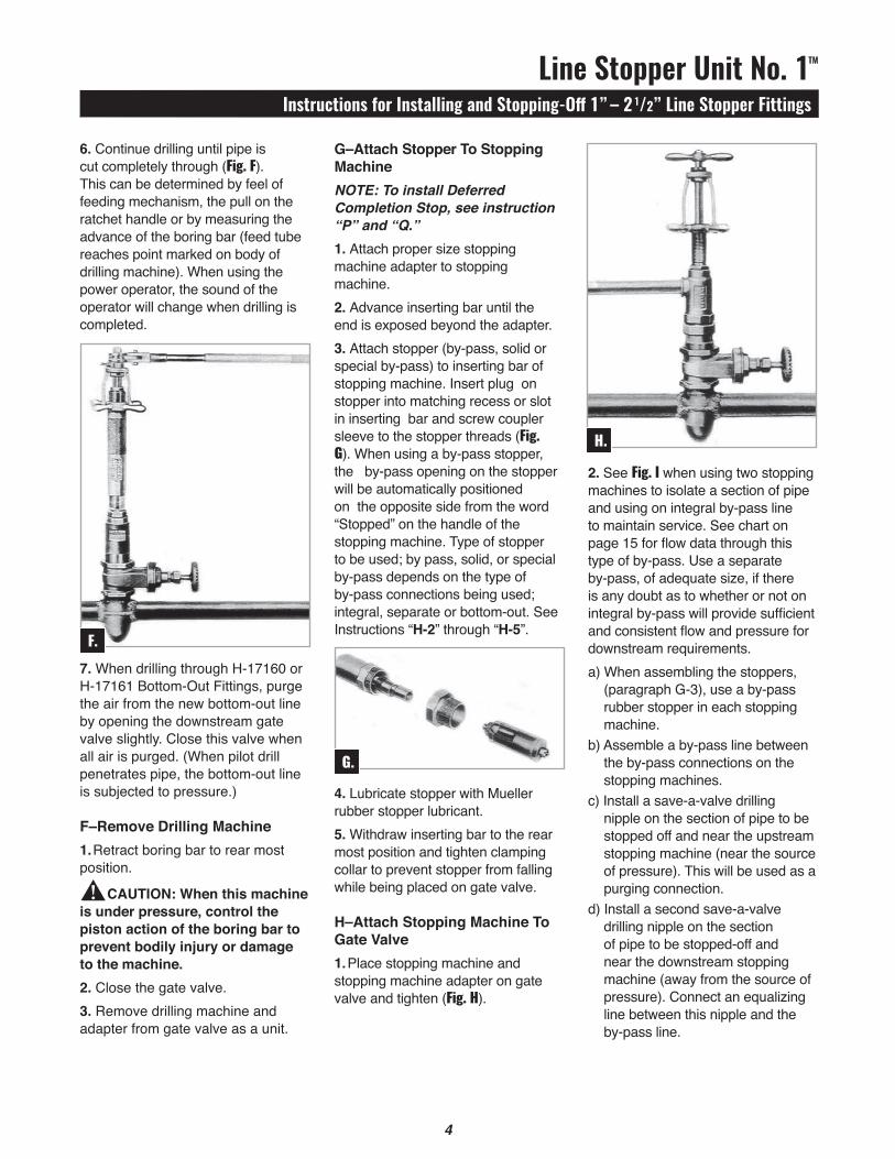
G–Attach Stopper To Stopping MachineNOTE: To install Deferred Completion Stop , see instruction “P” and “Q.”1. Attach proper size stopping machine adapter to stopping machine.2. Advance inserting bar until the end is exposed beyond the adapter.3. Attach stopper (by-pass, solid or special by-pass) to inserting bar of stopping machine. Insert plug on stopper into matching recess or slot in inserting bar and screw coupler sleeve to the stopper threads (Fig. G). When using a by-pass stopper, the by-pass opening on the stopper will be automatically positioned on the opposite side from the word “Stopped” on the handle of the stopping machine. Type of stopper to be used; by pass, solid, or special by-pass depends on the type of by-pass connections being used; integral, separate or bottom-out. See Instructions “H-2” through “H-5”.
4. Lubricate stopper with Mueller rubber stopper lubricant. 5. Withdraw inserting bar to the rear most position and tighten clamping collar to prevent stopper from falling while being placed on gate valve.
H–Attach Stopping Machine To Gate Valve1. Place stopping machine and stopping machine adapter on gate valve and tighten (Fig. H).
6. Continue drilling until pipe is cut completely through (Fig. F). This can be determined by feel of feeding mechanism, the pull on the ratchet handle or by measuring the advance of the boring bar (feed tube reaches point marked on body of drilling machine). When using the power operator, the sound of the operator will change when drilling is completed.
7. When drilling through h-17160 or h-17161 Bottom-Out Fittings, purge the air from the new bottom-out line by opening the downstream gate valve slightly. Close this valve when all air is purged. (When pilot drill penetrates pipe, the bottom-out line is subjected to pressure.)
F–Remove Drilling Machine1. retract boring bar to rear most position.
CAUTION: When this machine is under pressure, control the piston action of the boring bar to prevent bodily injury or damage to the machine.2. Close the gate valve.3. remove drilling machine and adapter from gate valve as a unit.
2. See Fig. I when using two stopping machines to isolate a section of pipe and using on integral by-pass line to maintain service. See chart on page 15 for flow data through this type of by-pass. use a separate by-pass, of adequate size, if there is any doubt as to whether or not on integral by-pass will provide sufficient and consistent flow and pressure for downstream requirements.a) When assembling the stoppers,
(para graph G-3), use a by-pass rubber stopper in each stopping machine.
b) Assemble a by-pass line between the by-pass connections on the stopping machines.
c) Install a save-a-valve drilling nipple on the section of pipe to be stopped off and near the upstream stopping machine (near the source of pressure). This will be used as a purging connection.
d) Install a second save-a-valve drilling nipple on the section of pipe to be stopped-off and near the downstream stopping machine (away from the source of pressure). Connect an equalizing line between this nipple and the by-pass line.
F.
G.
H.
!

Line Stopper Unit No. 1TM
Instructions for Installing and Stopping-Off 1” – 2 1/2” Line Stopper Fittings
5
I.
J.
Equalizing Line
Upper Equalizing Valve
Arrow on handle should point as shown
Arrow on handle should point as shown
Integral By-Pass Line
Lower Equalizing Valve
Purging Connection
Section to be Isolated
Save-A-Valve Drilling NippleUpstream Installation
Direction of Flow
Downstream Installation
Equalizing Line
Upper Equalizing Valve
Arrow on handle should point as shown
Arrow on handle should point as shown
Separate By-Pass Line
Lower Equalizing Valve
Purging Connection
Section to be Isolated
Save-A-Valve Drilling Nipple
Upstream Installation
Downstream Installation
Direction of Flow
Connect on equalizing line between this nipple and the by-pass line.
e) Tighten the plugs in by-pass connections of the stopping machine bodies.
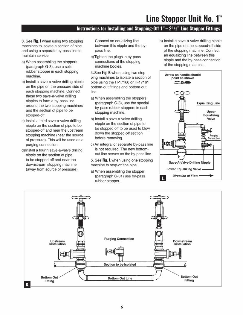
4. See Fig. K when using two stop ping machines to isolate a section of pipe using the h-17160 or h-17161 bottom-out fittings and bottom-out line.a) When assembling the stoppers
(para graph G-3), use the special by-pass rubber stoppers in each stopping machine.
b) Install a save-a-valve drilling nipple on the section of pipe to be stopped off to be used to blow down the stopped-off section before removing.
c) An integral or separate by-pass line is not required. The new bottom-out line serves as the by-pass line.
5. See Fig. L when using one stopping machine to stop-off the pipe.a) When assembling the stopper
(para graph G-31) use by-pass rubber stopper.
3. See Fig. J when using two stopping machines to isolate a section of pipe and using a separate by-pass line to maintain service.a) When assembling the stoppers
(para graph G-3), use a solid rubber stopper in each stopping machine.
b) Install a save-a-valve drilling nipple on the pipe on the pressure side of each stopping machine. Connect these two save-a-valve drilling nipples to form a by-pass line around the two stopping machines and the section of pipe to be stopped-off.
c) Install a third save-a-valve drilling nipple on the section of pipe to be stopped-off and near the upstream stopping machine (near the source of pressure). This will be used as a purging connection.
d) Install a fourth save-a-valve drilling nipple on the section of pipe to be stopped-off and near the downstream stopping machine (away from source of pressure).
b) Install a save-a-valve drilling nipple on the pipe on the stopped-off side of the stopping machine. Connect an equalizing line between this nipple and the by-pass connection of the stopping machine.
Line Stopper Unit No. 1TM
Instructions for Installing and Stopping-Off 1” – 2 1/2” Line Stopper Fittings
6
K.
Upstream Installation
Downstream Installation
Purging Connection
Section to be Isolated
Bottom Out Line Bottom Out Fitting
Bottom Out Fitting
7
L.
Upper Equalizing
Valve
Arrow on handle should point as shown
Lower Equalizing Valve
Save-A-Valve Drilling Nipple
Direction of Flow
Equalizing Line
Purging Connection

Line Stopper Unit No. 1TM
Instructions for Installing and Stopping-Off 1” – 2 1/2” Line Stopper Fittings
7
13. After drilling is completed, retract the boring bar to its rear most position.
CAUTION: When this machine is under pressure, control the piston action of the boring bar to prevent bodily injury or damage to the machine.14. Close the gate valve.15. remove drilling machine and adapter from gate valve as a unit.
J–Placing By-Pass Line In Operation1. If integral by-pass line is being used between two stopping machines (Fig. L), place the line in operation by:a) Remove the plug from tee
in equalizing line, then open upstream stopping machine gate valve slightly
b) Open upper valve in equalizing line until all air is purged from by-pass line through the open tee. Close the upper valve and pressure will build up in the by-pass line.
c) Open both stopping machine gate valves fully. By-pass line is now in operation.
2. If separate by-pass line is being used around the two stopping machines (J.), place the line in operation by:a) Remove the plug from tee in
equalizing line, then open gate valve on up stream by-pass connection.
b) Open upper valve in equalizing line until all air is purged from by-pass line through the open tee. Close upper valve in equalizing line and pressure will build up in the by-pass line.
c) Open gate valve on downstream by pass connection. By-pass line is now in operation.
Installation Of Save-A-Valve Drilling Nipples (Fig. M)
(See Mueller Gas Distribution Products Catalog for tool kits containing attachments, drilling equipment and valve needed to per form this operation.)
1. Clean surface of pipe where nipple is to be welded or service clamp attached.2. remove completion plug and cap before welding.3. Place nipple in position and weld to line or attach service clamp to line and then attach nipple to clamp.4. Screw test cap on nipple, apply air pressure and test for leaks with soap suds.5. remove test cap.6. Attach Mueller gate valve and open fully.7. Attach proper size machine adapter nipple and drilling tools to Mueller Drilling Machines.8. Apply Mueller cutting grease to drill.9. Place drilling machine and drilling machine adapter on gate valve and tighten securely.10. Advance boring bar until drill contacts pipe. retract the boring bar a small amount.11. Start drilling operation. When hand operating the drilling machine, begin with a light even feed, then a heavier feed, then finish drilling with a light even feed.12. Continue drilling until hole is drilled. This can be determined by feel of feeding mechanism, the pull on the ratchet handle or by measuring the advance of the boring bar.
3. If h-17160 or h-17161 Bottom-Out Fittings and bottom-out line is being used, (Fig. K), the bottom-out line is the by-pass line and was already placed in operation during the drilling out of the pipe.4. If using one stopping machine to stop -off the pipe, (Fig. L), purge the air from the equalizing line by:a) Remove plug from tee in
equalizing line, then open stopping machine gate valve slightly.
b) Open upper valve in equalizing line until all air is purged from the equalizing line through the open tee. Close the upper valve and pressure will build up in equalizing line.
c) Replace plug in tee in equalizing line.
K–Insert Stopper Into Fitting1. Turn the T-handle on the top of the stopping machine so that the arm with the arrow having the word “Stopped” on it points toward the section of pipe to be stopped-off. (When using by-pass rubber stoppers, this locates the by-pass on the stopper in the proper position.)2. Open stopping machine gate valve and advance inserting bar of stopping machine until the rubber stopper contacts the bottom of the fitting. DO NOT rotate T-handle.3. hold inserting bar in this position by placing yoke of the machine in the collar of the inserting bar (Fig. H).
L–Expand Stopper In Fitting1. Turn feed nut and yoke of stopping machine clockwise a little at a time with a short pause after each turn.
CAUTION: DO NOT rotate T-handle. Continue to compress the stopper in this manner until the line is stopped-off. This may be tested by use of the purging connection or any other opening that may be avail able in the section of pipe that is stopped off.
M.
!
!
Line Stopper Unit No. 1TM
Instructions for Installing and Stopping-Off 1” – 2 1/2” Line Stopper Fittings
8
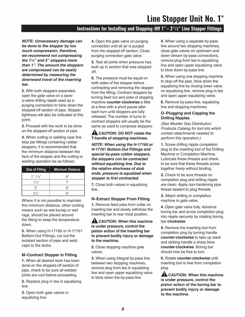
4. Open the gate valve on purging connection until all air is purged from the stopped-off section. Close purging connection gate valve.5. Test all joints when pressure has built up in section that was stopped off.6. The pressure must be equal on both sides of the stopper before contracting and removing the stopper from the fit ting. Contract stoppers by turning feed nut and yoke of stopping machine counter-clockwise a little at a time with a short pause after each turn until stoppers are fully released. The number of turns to contract stoppers will usually be the same as used to compress stop pers.
CAUTION: DO NOT rotate the T-handle of stopping machines. NOTE: When using the H-17160 or H-17161 Bottom-Out Fittings and special by-pass rubber stoppers, the stoppers con be contracted without equalizing line. Due to the relative shortness of stub ends, pressure is equalized when stopper is first contracted.7. Close both valves in equalizing line.
N–Extract Stopper From Fitting1. remove feed yoke from collar on inserting bar and slowly withdraw the inserting bar to rear most position.
CAUTION: When this machine is under pressure, control the piston action of the inserting bar to prevent bodily injury or damage to the machine.2. Close stopping machine gate valves.3. When using integral by-pass line between two stopping machines, remove plug from tee in equalizing line and open upper equalizing valve to blow down the by-pass line.
NOTE: Unnecessary damage can be done to the stopper by too much compression, therefore, we recommend not compressing the 11/2” and 2” stoppers more than 1”. The amount the stoppers are compressed can be easily determined by measuring the downward travel of the inserting bar.2. With both stoppers expanded, open the gate valve on a save-a-valve drilling nipple used as a purging connection to blow down the stopped-off section of pipe. Stopper tightness will also be indicated at this point.3. Proceed with the work to be done on the stopped-off section of pipe.4. When cutting or welding near line stop per fittings containing rubber stoppers, it is recommended that the minimum distance between the face of the stopper and the cutting or welding operation be as follows:
Where it is not possible to maintain this minimum distance, other cooling means such as wet burlap or wet rags, should be placed around the fitting to keep the temperature down.5. When using h-17160 or h-17161 Bot tom-Out Fittings, cut out the isolated section of pipe and weld caps to the stubs.
M–Contract Stopper In Fitting1. When all desired work has been done on the stopped-off section of pipe, check to be sure all welded joints are cool be fore proceeding.2. replace plug in tee in equalizing line.3. Open both gate valves in equalizing line.
4. When using a separate by-pass line around two stopping machines, close gate valves on upstream and down stream by-pass connections, remove plug from tee in equalizing line and open upper equalizing valve to blow down by-pass line.5. When using one stopping machine to stop-off the pipe, blow down the equalizing line by closing lower valve on equalizing line, remove plug in tee and open upper equalizing valve.6. remove by-pass line, equalizing line and stopping machines. O–Plugging and Capping the Drilling Nipples(See Mueller Gas Distribution Products Catalog for tool kits which contain attachments needed to perform this operation.)1. Screw drilling nipple completion plug to the inserting tool of the Drilling Machine or Completion Machine. Lubricate these threads and check to be sure that these threads screw together freely without binding. 2. Check to be sure threads on completion plug and drilling nipple are clean. Apply non-hardening pipe thread sealant to plug threads.3. Attach drilling or completion machine to gate valve.4. Open gate valve fully. Advance boring bar and screw completion plug into nipple securely by rotating boring bar clockwise.5. remove the inserting tool from completion plug by turning handle counter-clockwise to take up slack and striking handle a sharp blow counter-clockwise. Boring bar should now be free to turn.6. rotate counter-clockwise until inserting tool is free from completion plug.
CAUTION: When this machine is under pressure, control the piston action of the boring bar to prevent bodily injury or damage to the machine.
SizeofFitting minimumDistance
1”,11/4” 6”
11/2” 7”
2” 8”
21/2” 9”
!
!
!
9

Line Stopper Unit No. 1TM
Instructions for Installing and Stopping-Off 1” – 2 1/2” Line Stopper Fittings
9
7. Tighten plug in by-pass connection in stopping machine body.8. Open gate valve fully.9. Advance inserting bar (hold inserting bar down with feed yoke if desired) and screw completion plug into fitting with a clock wise rotation.10. remove plug inserting tool from the completion plug by turning the T-handle in a counter-clockwise rotation.11. retract inserting bar to rear most position.
CAUTION: When this machine is under pressure, control the piston action of the boring bar to prevent bodily injury or damage to the machine.12. remove stopping machine and adapter from gate valve as a unit. remove the gate valve from the fitting.13. Tighten the completion plug with the completion plug wrench.14. Apply non-hardening pipe thread sealant to completion cap threads and screw cap tightly on fitting (Fig. O).
15. Test entire fitting again with soapsuds.16. Refill trench.
Q–Future Removal Of Completion Plug(Deferred completion stopper may also be removed by following these instructions.)1. remove completion cap and loosen completion plug slightly with the completion plug wrench, but DO NOT remove.
7. remove drilling machine or completion machine and gate valve.8. Tighten completion plug with wrench. 9. Apply non-hardening pipe thread sealant to completion cap threads and screw cap tightly onto nipple. Test for leaks with soapsuds.P-Install Completion Plug In Line Stopper Fitting(Deferred completion stopper may also be installed by following these instructions Fig. N).
1. remove stopper from stopping machine.2. Screw plug inserting tool into the inside thread on top of the completion plug. Lubricate these threads and check to be sure that these threads screw together freely without binding.3. Attach the plug inserting tool with completion plug, to the right-hand inside threads of the inserting bar (Fig. N).4. Check to be sure threads on completion plug and fitting are clean. On plugs having an O-ring seal, coat the O-ring with heavy grease. On plugs having tapered threads and no O-ring, coat the threads with non-hardening pipe thread sealant.5. Withdraw inserting bar to rear most position.6. Place stopping machine and adapter on gate valve and tighten securely. When installing deferred completion stopper, change machine adapter.
2. Attach plug extracting tool to the inserting bar of the stopping machine.a) Insert lug on top of plug extracting
tool into matching recess or slot in inserting bar.
b) Screw coupler sleeve to plug extracting tool threads.
3. Open gate valve fully and attach it to the fitting.4. Withdraw inserting bar of stopping ma chine to rear most position and tighten clamping collar.5. Attach stopping machine adapter to stopping machine. Place stopping machine and adapter on gate valve and tighten securely. When removing a deferred completion stopper, use special stopping machine adapter.6. Loosen clamping collar and slowly advance inserting bar until plug extracting tool contacts the completion plug.7. rotate inserting bar clockwise until plug extracting tool firmly engages the threads in the top of the completion plug.8. rotate inserting bar counter-clockwise until completion plug is unscrewed from the fitting.9. Withdraw inserting bar to rear most position, being sure the completion plug clears the valve gate.10. Close the gate valve.11. remove stopping machine and adapter from gate valve as a unit.12. Advance inserting bar until completion plug and plug extracting tool are ex posed.13. remove completion plug and extracting tool from inserting bar. NOTE: Left-hand threads between plug extracting tool and inserting bar.14. Refer back to instruction “G” and proceed with use of the fitting.
N.
O.
!
P.
Line Stopper Unit No. 1TM
Instructions for Stopping-Off 11/2” – 2” Extension Stopper Fittings
10
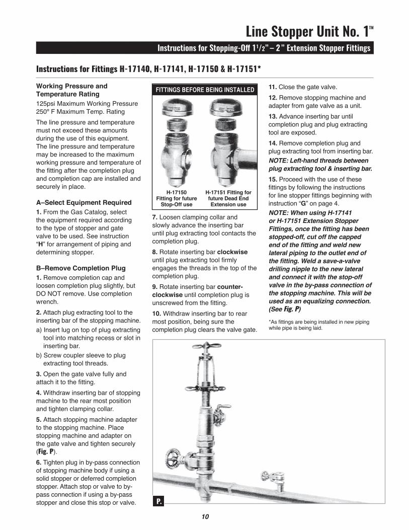
7. Loosen clamping collar and slowly advance the inserting bar until plug extracting tool contacts the completion plug.8. rotate inserting bar clockwise until plug extracting tool firmly engages the threads in the top of the completion plug.9. rotate inserting bar counter-clockwise until completion plug is unscrewed from the fitting.10. Withdraw inserting bar to rear most position, being sure the completion plug clears the valve gate.
Working Pressure and Temperature Rating125psi Maximum Working Pressure 250º F Maximum Temp. rating The line pressure and temperature must not ex ceed these amounts during the use of this equipment. The line pressure and temperature may be increased to the maximum working pressure and temperature of the fitting after the completion plug and completion cap are installed and securely in place.
A–Select Equipment Required1. From the Gas Catalog, select the equipment required according to the type of stopper and gate valve to be used. See instruction “H” for arrangement of piping and determining stopper.
B–Remove Completion Plug1. remove completion cap and loosen completion plug slightly, but DO NOT remove. use completion wrench.2. Attach plug extracting tool to the inserting bar of the stopping machine.a) Insert lug on top of plug extracting
tool into matching recess or slot in inserting bar.
b) Screw coupler sleeve to plug extracting tool threads.
3. Open the gate valve fully and attach it to the fitting.4. Withdraw inserting bar of stopping ma chine to the rear most position and tighten clamping collar.5. Attach stopping machine adapter to the stopping machine. Place stopping machine and adapter on the gate valve and tighten securely (Fig. P).6. Tighten plug in by-pass connection of stopping machine body if using a solid stopper or deferred completion stopper. Attach stop or valve to by-pass connection if using a by-pass stopper and close this stop or valve.
11. Close the gate valve.12. remove stopping machine and adapter from gate valve as a unit.13. Advance inserting bar until completion plug and plug extracting tool are exposed.14. remove completion plug and plug extracting tool from inserting bar. NOTE: Left-hand threads between plug extracting tool & inserting bar.15. Proceed with the use of these fittings by following the instructions for line stopper fittings beginning with instruction “G” on page 4.NOTE: When using H-17141 or H-17151 Ex tension Stopper Fittings, once the fitting has been stopped-off, cut off the capped end of the fitting and weld new lateral piping to the outlet end of the fitting. Weld a save-a-valve drilling nipple to the new lateral and connect it with the stop-off valve in the by-pass connection of the stopping machine. This will be used as an equalizing connection. (See Fig. P)
Instructions for Fittings H-17140, H-17141, H-17150 & H-17151*
*As fittings are being installed in new piping while pipe is being laid.
FIttINgSBeForeBeINgINStalleD
H-17150 Fitting for future
Stop-Off use
H-17151 Fitting for future Dead EndExtension use
11

Line Stopper Unit No. 1TM
Instructions for Installing and Stopping-Off 11/2” – 2” Extension Stopper Fittings
Working Pressure and Temperature Rating125psi Maximum Working Pressure 250º F Maximum Temp. rating The line pressure and temperature must not exceed these amounts during the installation and of these fittings. The line pressure and temperature may be increased to the maximum working pressure and temperature of the fitting after the completion plug and completion cap are installed and securely in place.The h-17142 and h-17152 Fittings are used with 4” size pipe and smaller. The h-17143 and 17153 Fittings can be used with 5” size pipe and larger.
A–Select Equipment Required1. From the Gas Catalog, select the equipment required according to the size of the fitting, type of stopper and gate valve to be used. See instruction “H” for arrangement of piping.
B–Install The Extension Stopper Fitting1. Thoroughly clean the pipe where the fitting is to be attached. 2. remove the completion cap and loosen the completion plug slightly.3. Place the fitting in the desired position and weld to the pipe. It may be necessary to shape the inlet of the fitting to fit the pipe (Fig. Q).4. remove the completion plug.
Installation Instructions for Fittings H-17142, H-17143, H-17152 & H-17153 for Lateral Connections
11
8. Tighten plug in by-pass connection of stopping machine body if using a solid stopper or deferred completion stopper. Attach a stop or valve to the by-pass connection if using a by-pass stopper and close this valve or stop.9. Screw test cap onto outlet threads of fitting, apply air pressure and test for leaks using soapsuds (Fig. T).10. remove test cap.
C–Attach Line Stopper EquipmentNOTE: To install a deferred completion stop per, see instructions “P’’ and “Q.”1. Attach gate valve to the top of the fitting and fully open (Fig. R).
2. Attach proper size stopping machine adapter to the stopping machine.3. Advance the inserting bar of stopping machine until the end is exposed beyond the adapter.4. Attach stopper (by-pass or solid) to inserting bar of stopping machine by inserting plug on stopper into matching recess or slot in inserting bar and screwing coupler sleeve to the stopper threads. Figure 8. When using a by-pass stopper, the by-pass opening on the stopper will be automatically positioned on the opposite side from the word “Stopped” on the handle of the stopping machine.5. Lubricate stoppers with Mueller rubber stopper lubricant.6. Withdraw inserting bar to the rearmost position and tighten clamping collar.7. Place stopping machine and adapter on gate valve and tighten securely (Fig. S).
Q.
R.S.
T.

G–Expand Stopper In Fitting1. Turn feed nut and yoke of stopping machine clockwise a little at a time with a short pause after each turn.
CAUTION: DO NOT rotate T-handle. Continue to compress the stopper in this manner until the line is stopped off. NOTE: Unnecessary damage may be done to the stopper by too much compression, therefore, we recommend not compressing the 11/2 and 2” toppers more than 1”. The amount the stoppers are compressed can be easily determined by measuring the downward travel of the inserting bar.H–Remove Drilling Equipment1. With the fitting stopped off, remove the drilling machine and drilling machine adapter as a unit. (Fig. V).
I–Attach Lateral Piping1. If using threaded connections, attach pipe to outlet threads of fitting.2. If using welding connections, cut off the threaded outlet end of the fitting and weld pipe to the outlet end of the fitting (Fig. W).
Line Stopper Unit No. 1TM
Instructions for Installing and Stopping-Off 11/2” – 2” Extension Stopper Fittings
D–Attach Drilling Equipment(For detailed instructions, see operating instructions for D-5 Drilling Machines).1. Attach proper size drilling machine adapter to the drilling machine.2. Attach boring bar extension, drill holder and drill to the boring bar of the drilling machine. If power operating the D-5 Drilling Machine, use the high-speed shell cutter instead of the drill. 3. Coat shell cutter and pilot drill or drill thoroughly with Mueller cutting grease. retract boring bar of machine to rear most position.4. Attach drilling machine and adapter to outlet end of the fitting (Fig. U).
E–Drill The Pipe Line1. Advance the boring bar until the point of the drill contacts the pipe. retract the boring bar a small amount so as not to start the drill in a bind.2. Start the drilling operation and drill a hole in the pipeline.3. After the hole is drilled, retract the boring bar to rearmost position.
CAUTION: When this machine is under pressure, control the piston action of the boring bar to prevent bodily injury or damage to the machine.
F–Insert Stopper Into Fitting1. Turn the T-handle on the top of the stopping machine so that the arm having the word “Stopped” on it points toward the drilling machine.2. With the gate valve fully open, advance the inserting bar of the stopping machine until the rubber stopper contacts the bottom of the fitting.3. hold inserting bar in this position by placing yoke of the machine in the collar of the inserting bar.
CAUTION: DO NOT rotate T-handle.
!
!
12
U.
NOTE: When cutting or welding near fittings containing rubber stoppers, it is recommended that the minimum distance between the face of the stopper and the cutting or welding operation be as follows:
Where it is not possible to maintain this minimum distance, other cooling means such as wet burlap or wet rags, should be placed around the fitting to keep the temperature down.
V.
!
SizeofFitting minimumDistance
11/2” 7”
2” 8”

12
Line Stopper Unit No. 1TM
Instructions for Installing and Stopping-Off 11/2” – 2” Extension Stopper Fittings
Extend the lateral pipe to the nearest available shut-off in the line.If using a by-pass rubber stopper, install a save-a-valve drilling nipple on the new lateral pipe and connect this nipple with the stop in the by-pass connection of the stop-ping machine to form an equalizing line. Install a second save·a-valve drilling nipple on the new lateral pipe downstream near the shut-off point. This connection will be used as a purging connection.If using a solid rubber stopper or deferred completion stopper, install a save-a-valve drilling nipple on the pipe line which is the source of pressure. Install a second save-a valve drilling nipple on the new lateral pipe near the stopping machine and connect the two nipples to form an equalizing line. In stall a third save-a-valve drilling nipple on the new lateral pipe downstream near the shut-off point to be used as a purging connection.To install save-a-valve drilling nipples, see instruction “I”.
W.
13
J–Place Lateral Pipe In Operation1. If using a by-pass stopper, apply pressure to the lateral by opening the valve on the save-a-valve drilling nipple in equalizing line and open the stop in the by-pass connection of the stopping ma chine. The new lateral is purged of air by opening valve on save-a-valve drilling nipple installed downstream near shut-off point. When all air is purged, close this valve.If using a solid rubber stopper or deferred completion stopper, apply pressure to apply pressure to the lateral by opening the valve on the nipple on the pipe which is source of pressure and opening the valve on the nipple on the new lateral near stopping machine. The new lateral is purged of air by opening valve on nipple installed downstream near shut-off point. When all air is purged, close this valve.2. The pressure must be equal on both sides of the stopper before contracting and re moving it from the fitting. When pressure has built up in the new lateral, contract the stopper by turning the feed nut and yoke of the stopping machine counter-clockwise a little at a time with a short pause after each turn until the stopper is fully released.
CAUTION: DO NOT turn the T-handle of the stopping machine.
K–Extract Stopper From Fitiing1. With stopper fully contracted, remove feed yoke from collar on inserting bar and slowly withdraw the inserting bar to rearmost position .2. Close stopping machine gate valve.3. If using a by-pass stopper, close the valve on the save-a-valve drilling nipple and close the stop in the by-pass connection of the stopping machine. remove the equalizing line. If using a solid rubber stopper or deferred completion stopper, close valves on both save-a-valve drilling nipples in equalizing line and remove the equalizing line.4. remove the stopping machine and adapter from the gate valve as a unit.5. Install completion plugs and caps on the save-a-valve drilling nipples. See instruction “O” on page 8 for instructions.
L–Install Completion Plug(Deferred completion stoppers may also be installed by following these instructions.)1. remove stopper from stopping machine2. Screw the plug inserting tool to the inside thread of the completion plug. Lubricate these threads and check to be sure that the threads screw together freely without binding.3. Attach the plug inserting tool, with the completion plug to the right-hand inside threads of the inserting bar (Fig. X).
X.
!

Line Stopper Unit No. 1TM
Flow Chart for Line Stopper Fittings
4. Check to be sure threads on completion plug and fitting are clean. On plugs having an O-ring seal, coat the O-ring with heavy grease. On plugs having tapered threads and no O-ring, coat the threads with non-hardening pipe thread sealant.5. Withdraw inserting bar to rearmost position. 6. Place stopping machine and adapter on gate valve and tighten securely. When installing a deferred completion stopper, change machine adapter to Part Number 37187.7. Tighten plug or close the stop in by-pass connection in stopping machine body.8. Open gate valve fully.9. Advance inserting bar (hold inserting bar down with feed yoke if desired), and screw completion plug into fitting by rotating inserting bar clockwise.10. remove plug inserting tool from the completion plug by turning the T-handle in a counter-clockwise rotation.11. rotate counter-clockwise until plug inserting tool is free from the completion plug.12. remove stopping machine and adapter from the gate valve as a unit. Remove the gate valve from the fitting.13. Tighten the completion plug with the completion plug wrench.14. Apply pipe thread sealant to completion cap threads and screw cap tightly onto the fitting (X.).15. Test entire fitting again with soapsuds.16. Refill trench.
M–For Future Removal Of Completion Plug(Deferred completion stoppers may also be removed by following these instructions.)1. Refer back to instruction “Q” on page 9 for instructions to remove the completion plug.
14
To obtain total pressure drop determine the pressure drop as listed in the table corresponding to the upstream pressure to be maintained, and the maximum flow rote required, and odd to the pressure drop in the by-pass line. The by-pass line pressure drops are given for 100 ft. of by-pass line. For pressure loss of actual length used, divide actual length in feet by 100, and multiply this factor into the value in the table.Example: A two inch line is to be stopped off using 2” By-Pass rubber Stoppers. A 11/2” by pass line, 60 ft. long will be used, connected with reducer to the 11/4” standard by-pass connection. The upstream pressure will be maintained at 50psig, and
it is desired to pass a maximum of 10,000 cubic feet per hour during the operation. From the table the pressure drop in the stoppers is 14.77psi. For 60’ of 11/2” line the by-pass line drop will be 1.09 x 60/100 = .65psi. Total drop = 14.77 + .65 = 15.42psi. leaving 34.58psig available for distri bution at outlet end.Where the letter N appears in table, the pressure drop is considered negligible. use a separate by-pass of adequate size if there is any doubt as to whether or not on integral by-pass will provide sufficient and consistent flow and pressure for downstream requirements.
Flow Rate Pressure Drop Pressure Drop Through Cu. Ft. Per Through Upstream Hour of Up-Stream 100 Ft. of Pipe – psi Pressure .60 Sp. Gr. and Down- psig Gas at Stream By-Pass Pipe Size Standard Stoppers Condtions psi 11/4” 11/2” 2” 3”
2” BY-PASS RUBBER STOPPER 125 10,000 6.54 .88 .41 .12 .11 20,000 27.08 3.79 1.75 .50 .07 30,000 65.59 12.25 5.60 1.02 .27
100 10,000 8.01 1.10 .51 .15 .02 20,000 33.85 5.28 2.44 .70 .10 25,000 55.88 11.05 5.07 1.45 .22
75 5,000 2.54 .37 .17 .05 N 10,000 10.38 1.48 .69 .20 N 20,000 46.20 9.83 4.55 1.31 .18
50 2,000 .56 .09 .04 N N 5,000 3.56 .53 .25 .07 N 10,000 14.77 2.34 1.09 .31 .04 15,000 36.52 8.95 4.1 4 1.19 .17
15 2,000 1.24 .209 .70 N N 5,000 8.79 1.53 .10 .20 N
10 1,000 .37 .07 .03 N N 2,000 2.74 .27 .1 3 N N 3,000 3.44 .59 .27 .08 N
5 1,000 .48 .09 .04 N N 2,000 1.9 .33 .15 .05 N 3,000 4.4 .83 .39 .11 N
Pressure Drop through Mueller Line Stopper Fittings w/Intergral By-Pass LIne

14
Line Stopper Unit No. 1TM
Notes
15

Gas (Water)[email protected]
Form 8517 – Rev 05/17
Copyright © 2017 Mueller Co., LLC. All rights reserved.The trademarks, logos and service marks displayed in this document herein are the property of Mueller Co., LLC, its affiliates or other third parties. Products marked with a section symbol ( § ) are subject to patents or patent applications. For details, visit www.mwppat.com. These products are intended for use in potable water applications. Please contact your Mueller Sales or Customer Service Representative concerning any other application(s).
Reliable ConnectionsTM
International1.423.490.9555www.mueller-international.cominternational@muellercompany.com