mtl - fnico non-incendive fieldbus system.pdf
TRANSCRIPT

7/27/2019 MTL - FNICO Non-Incendive Fieldbus System.pdf
http://slidepdf.com/reader/full/mtl-fnico-non-incendive-fieldbus-systempdf 1/36
FNICO Non-Incendive Fieldbus System
AN9027
Application Note AN9027

7/27/2019 MTL - FNICO Non-Incendive Fieldbus System.pdf
http://slidepdf.com/reader/full/mtl-fnico-non-incendive-fieldbus-systempdf 2/36
ii AN9027-4 May 2005

7/27/2019 MTL - FNICO Non-Incendive Fieldbus System.pdf
http://slidepdf.com/reader/full/mtl-fnico-non-incendive-fieldbus-systempdf 3/36
iii
1 Introduction . . . . . . . . . . . . . . . . . . . . . . . . . . . . . . . . . . . . . . . . . . . . . . . . . . . . . . . . . . . . . 1
1.1 About this document . . . . . . . . . . . . . . . . . . . . . . . . . . . . . . . . . . . . . . . . . . . . . . . . . . . . . . . . . . . . . . . . . . . . . 1
1.2 Background . . . . . . . . . . . . . . . . . . . . . . . . . . . . . . . . . . . . . . . . . . . . . . . . . . . . . . . . . . . . . . . . . . . . . . . . . . 1
1.3 Principle . . . . . . . . . . . . . . . . . . . . . . . . . . . . . . . . . . . . . . . . . . . . . . . . . . . . . . . . . . . . . . . . . . . . . . . . . . . . . 1
1.4 Cables . . . . . . . . . . . . . . . . . . . . . . . . . . . . . . . . . . . . . . . . . . . . . . . . . . . . . . . . . . . . . . . . . . . . . . . . . . . . . 21.5 Power supplies . . . . . . . . . . . . . . . . . . . . . . . . . . . . . . . . . . . . . . . . . . . . . . . . . . . . . . . . . . . . . . . . . . . . . . . . 2
1.6 Field devices . . . . . . . . . . . . . . . . . . . . . . . . . . . . . . . . . . . . . . . . . . . . . . . . . . . . . . . . . . . . . . . . . . . . . . . . . . 2
1.7 Documentation and inspection . . . . . . . . . . . . . . . . . . . . . . . . . . . . . . . . . . . . . . . . . . . . . . . . . . . . . . . . . . . . . . 3
1.8 Conclusion . . . . . . . . . . . . . . . . . . . . . . . . . . . . . . . . . . . . . . . . . . . . . . . . . . . . . . . . . . . . . . . . . . . . . . . . . . . 3
2 Power supplies . . . . . . . . . . . . . . . . . . . . . . . . . . . . . . . . . . . . . . . . . . . . . . . . . . . . . . . . . . . 3
2.1 Introduction . . . . . . . . . . . . . . . . . . . . . . . . . . . . . . . . . . . . . . . . . . . . . . . . . . . . . . . . . . . . . . . . . . . . . . . . . . . 3
2.2 Non-incendive output . . . . . . . . . . . . . . . . . . . . . . . . . . . . . . . . . . . . . . . . . . . . . . . . . . . . . . . . . . . . . . . . . . . . 3
2.3 Host port . . . . . . . . . . . . . . . . . . . . . . . . . . . . . . . . . . . . . . . . . . . . . . . . . . . . . . . . . . . . . . . . . . . . . . . . . . . . 4
2.4 24V supply . . . . . . . . . . . . . . . . . . . . . . . . . . . . . . . . . . . . . . . . . . . . . . . . . . . . . . . . . . . . . . . . . . . . . . . . . . . 4
2.5 Screen terminals . . . . . . . . . . . . . . . . . . . . . . . . . . . . . . . . . . . . . . . . . . . . . . . . . . . . . . . . . . . . . . . . . . . . . . . 4
2.6 Status indicators . . . . . . . . . . . . . . . . . . . . . . . . . . . . . . . . . . . . . . . . . . . . . . . . . . . . . . . . . . . . . . . . . . . . . . . 4
3 Connecting field devices to a FNICO power supply . . . . . . . . . . . . . . . . . . . . . . . . . . . . . . . . . 5
3.1 Introduction . . . . . . . . . . . . . . . . . . . . . . . . . . . . . . . . . . . . . . . . . . . . . . . . . . . . . . . . . . . . . . . . . . . . . . . . . . . 5
3.2 Output voltage and current . . . . . . . . . . . . . . . . . . . . . . . . . . . . . . . . . . . . . . . . . . . . . . . . . . . . . . . . . . . . . . . . 5
3.3 Cable resistance . . . . . . . . . . . . . . . . . . . . . . . . . . . . . . . . . . . . . . . . . . . . . . . . . . . . . . . . . . . . . . . . . . . . . . . 5
3.4 Field device, voltage and current . . . . . . . . . . . . . . . . . . . . . . . . . . . . . . . . . . . . . . . . . . . . . . . . . . . . . . . . . . . . 5
3.5 Typical calculation for IIC (9111-NI) power supply . . . . . . . . . . . . . . . . . . . . . . . . . . . . . . . . . . . . . . . . . . . . . . . . 6
3.6 Typical calculation for a IIB (9112-NI) power supply . . . . . . . . . . . . . . . . . . . . . . . . . . . . . . . . . . . . . . . . . . . . . . . 7
3.7 Software calculator tool . . . . . . . . . . . . . . . . . . . . . . . . . . . . . . . . . . . . . . . . . . . . . . . . . . . . . . . . . . . . . . . . . . 8
4 Commissioning and fault finding in a FNICO system . . . . . . . . . . . . . . . . . . . . . . . . . . . . . . . . 8
4.1 Introduction . . . . . . . . . . . . . . . . . . . . . . . . . . . . . . . . . . . . . . . . . . . . . . . . . . . . . . . . . . . . . . . . . . . . . . . . . . . 8
4.2 Facilities . . . . . . . . . . . . . . . . . . . . . . . . . . . . . . . . . . . . . . . . . . . . . . . . . . . . . . . . . . . . . . . . . . . . . . . . . . . . 8
4.3 Specialist test equipment . . . . . . . . . . . . . . . . . . . . . . . . . . . . . . . . . . . . . . . . . . . . . . . . . . . . . . . . . . . . . . . . . . 8
4.4 Procedure . . . . . . . . . . . . . . . . . . . . . . . . . . . . . . . . . . . . . . . . . . . . . . . . . . . . . . . . . . . . . . . . . . . . . . . . . . . . 9
5 FNICO installation requirements . . . . . . . . . . . . . . . . . . . . . . . . . . . . . . . . . . . . . . . . . . . . . . 10
5.1 General . . . . . . . . . . . . . . . . . . . . . . . . . . . . . . . . . . . . . . . . . . . . . . . . . . . . . . . . . . . . . . . . . . . . . . . . . . . . 10
5.2 Cables . . . . . . . . . . . . . . . . . . . . . . . . . . . . . . . . . . . . . . . . . . . . . . . . . . . . . . . . . . . . . . . . . . . . . . . . . . . . . 11
6 Establishing safety compatibility between field devices and FNICO power supplies . . . . . . . . . 12
6.1 Intrinsically safe field devices . . . . . . . . . . . . . . . . . . . . . . . . . . . . . . . . . . . . . . . . . . . . . . . . . . . . . . . . . . . . . . 12
6.2 Non-incendive field devices . . . . . . . . . . . . . . . . . . . . . . . . . . . . . . . . . . . . . . . . . . . . . . . . . . . . . . . . . . . . . . . 13
6.3 EEx nL devices . . . . . . . . . . . . . . . . . . . . . . . . . . . . . . . . . . . . . . . . . . . . . . . . . . . . . . . . . . . . . . . . . . . . . . . . 13
6.4 Terminators and connecting blocks . . . . . . . . . . . . . . . . . . . . . . . . . . . . . . . . . . . . . . . . . . . . . . . . . . . . . . . . . . 136.5 Marking of IS devices used in a FNICO system . . . . . . . . . . . . . . . . . . . . . . . . . . . . . . . . . . . . . . . . . . . . . . . . . . 13
6.6 Re-use of intrinsically safe field devices . . . . . . . . . . . . . . . . . . . . . . . . . . . . . . . . . . . . . . . . . . . . . . . . . . . . . . . 13
7 Earthing . . . . . . . . . . . . . . . . . . . . . . . . . . . . . . . . . . . . . . . . . . . . . . . . . . . . . . . . . . . . . . . 13
7.1 Introduction . . . . . . . . . . . . . . . . . . . . . . . . . . . . . . . . . . . . . . . . . . . . . . . . . . . . . . . . . . . . . . . . . . . . . . . . . . 13
7.2 Trunks . . . . . . . . . . . . . . . . . . . . . . . . . . . . . . . . . . . . . . . . . . . . . . . . . . . . . . . . . . . . . . . . . . . . . . . . . . . . . 14
7.3 Screens/shields . . . . . . . . . . . . . . . . . . . . . . . . . . . . . . . . . . . . . . . . . . . . . . . . . . . . . . . . . . . . . . . . . . . . . . . 14
7.4 Other earths . . . . . . . . . . . . . . . . . . . . . . . . . . . . . . . . . . . . . . . . . . . . . . . . . . . . . . . . . . . . . . . . . . . . . . . . . 14
continued.....
CONTENTS PAGE
© 2005 MTL Instruments Group plc. All rights reserved.
AN9027-4 May 2005

7/27/2019 MTL - FNICO Non-Incendive Fieldbus System.pdf
http://slidepdf.com/reader/full/mtl-fnico-non-incendive-fieldbus-systempdf 4/36
iv
8 Cables and accessories . . . . . . . . . . . . . . . . . . . . . . . . . . . . . . . . . . . . . . . . . . . . . . . . . . . . 14
8.1 Cables . . . . . . . . . . . . . . . . . . . . . . . . . . . . . . . . . . . . . . . . . . . . . . . . . . . . . . . . . . . . . . . . . . . . . . . . . . . . . 14
8.2 Terminators . . . . . . . . . . . . . . . . . . . . . . . . . . . . . . . . . . . . . . . . . . . . . . . . . . . . . . . . . . . . . . . . . . . . . . . . . . 14
8.3 Wiring hubs and enclosures . . . . . . . . . . . . . . . . . . . . . . . . . . . . . . . . . . . . . . . . . . . . . . . . . . . . . . . . . . . . . . . 15
9 Wiring requirements for FNICO non-incendive circuits in division 2 locations . . . . . . . . . . . . . . 16
9.1 General . . . . . . . . . . . . . . . . . . . . . . . . . . . . . . . . . . . . . . . . . . . . . . . . . . . . . . . . . . . . . . . . . . . . . . . . . . . . 16
9.2 Non-incendive field wiring . . . . . . . . . . . . . . . . . . . . . . . . . . . . . . . . . . . . . . . . . . . . . . . . . . . . . . . . . . . . . . . . 17
9.3 Segregation of FNICO cables . . . . . . . . . . . . . . . . . . . . . . . . . . . . . . . . . . . . . . . . . . . . . . . . . . . . . . . . . . . . . 17
9.4 Conduit . . . . . . . . . . . . . . . . . . . . . . . . . . . . . . . . . . . . . . . . . . . . . . . . . . . . . . . . . . . . . . . . . . . . . . . . . . . . 17
9.5 Shields . . . . . . . . . . . . . . . . . . . . . . . . . . . . . . . . . . . . . . . . . . . . . . . . . . . . . . . . . . . . . . . . . . . . . . . . . . . . . 18
9.6 Cable identification . . . . . . . . . . . . . . . . . . . . . . . . . . . . . . . . . . . . . . . . . . . . . . . . . . . . . . . . . . . . . . . . . . . . 18
9.7 Preferred installation . . . . . . . . . . . . . . . . . . . . . . . . . . . . . . . . . . . . . . . . . . . . . . . . . . . . . . . . . . . . . . . . . . . . 18
9.8 Conclusion . . . . . . . . . . . . . . . . . . . . . . . . . . . . . . . . . . . . . . . . . . . . . . . . . . . . . . . . . . . . . . . . . . . . . . . . . . 18
10 Surge protection . . . . . . . . . . . . . . . . . . . . . . . . . . . . . . . . . . . . . . . . . . . . . . . . . . . . . . . . . 18
10.1 Introduction . . . . . . . . . . . . . . . . . . . . . . . . . . . . . . . . . . . . . . . . . . . . . . . . . . . . . . . . . . . . . . . . . . . . . . . . . . 18
10.2 Compatible surge protection devices . . . . . . . . . . . . . . . . . . . . . . . . . . . . . . . . . . . . . . . . . . . . . . . . . . . . . . . . . 18
10.3 Protecting the system . . . . . . . . . . . . . . . . . . . . . . . . . . . . . . . . . . . . . . . . . . . . . . . . . . . . . . . . . . . . . . . . . . . . 19
11 Mounting of FNICO power sup-plies in zone 2 and division 2 . . . . . . . . . . . . . . . . . . . . . . . . 2111.1 General . . . . . . . . . . . . . . . . . . . . . . . . . . . . . . . . . . . . . . . . . . . . . . . . . . . . . . . . . . . . . . . . . . . . . . . . . . . . 21
11.2 Typical installation . . . . . . . . . . . . . . . . . . . . . . . . . . . . . . . . . . . . . . . . . . . . . . . . . . . . . . . . . . . . . . . . . . . . . 21
11.3 Environmental considerations . . . . . . . . . . . . . . . . . . . . . . . . . . . . . . . . . . . . . . . . . . . . . . . . . . . . . . . . . . . . . . 21
11.4 Maintenance and fault finding . . . . . . . . . . . . . . . . . . . . . . . . . . . . . . . . . . . . . . . . . . . . . . . . . . . . . . . . . . . . . 22
11.5 Further combinations . . . . . . . . . . . . . . . . . . . . . . . . . . . . . . . . . . . . . . . . . . . . . . . . . . . . . . . . . . . . . . . . . . . 22
12 Certification and safety documentation of FNICO systems . . . . . . . . . . . . . . . . . . . . . . . . . . . 22
12.1 Introduction . . . . . . . . . . . . . . . . . . . . . . . . . . . . . . . . . . . . . . . . . . . . . . . . . . . . . . . . . . . . . . . . . . . . . . . . . . 22
12.2 MTL FNICO power supplies . . . . . . . . . . . . . . . . . . . . . . . . . . . . . . . . . . . . . . . . . . . . . . . . . . . . . . . . . . . . . . . 22
12.3 MTL terminator . . . . . . . . . . . . . . . . . . . . . . . . . . . . . . . . . . . . . . . . . . . . . . . . . . . . . . . . . . . . . . . . . . . . . . . 23
12.4 MTL 24V Zone 2/Division 2 power supply . . . . . . . . . . . . . . . . . . . . . . . . . . . . . . . . . . . . . . . . . . . . . . . . . . . . . 23
12.5 Cables . . . . . . . . . . . . . . . . . . . . . . . . . . . . . . . . . . . . . . . . . . . . . . . . . . . . . . . . . . . . . . . . . . . . . . . . . . . . . 2312.6 Interconnection blocks . . . . . . . . . . . . . . . . . . . . . . . . . . . . . . . . . . . . . . . . . . . . . . . . . . . . . . . . . . . . . . . . . . . 23
12.7 Enclosures and glands . . . . . . . . . . . . . . . . . . . . . . . . . . . . . . . . . . . . . . . . . . . . . . . . . . . . . . . . . . . . . . . . . . 23
12.8 Simple apparatus . . . . . . . . . . . . . . . . . . . . . . . . . . . . . . . . . . . . . . . . . . . . . . . . . . . . . . . . . . . . . . . . . . . . . . 23
12.9 Safety documentation . . . . . . . . . . . . . . . . . . . . . . . . . . . . . . . . . . . . . . . . . . . . . . . . . . . . . . . . . . . . . . . . . . . 23
12.10 Documenting the safety of a FNICO installation . . . . . . . . . . . . . . . . . . . . . . . . . . . . . . . . . . . . . . . . . . . . . . . . . . 23
12.11 Safety documentation for a FNICO system . . . . . . . . . . . . . . . . . . . . . . . . . . . . . . . . . . . . . . . . . . . . . . . . . . . . . 24
13 Appendix I : Simple apparatus and the ATEX directive . . . . . . . . . . . . . . . . . . . . . . . . . . . . . 25
13.1 Introduction . . . . . . . . . . . . . . . . . . . . . . . . . . . . . . . . . . . . . . . . . . . . . . . . . . . . . . . . . . . . . . . . . . . . . . . . . . 25
13.2 Standards . . . . . . . . . . . . . . . . . . . . . . . . . . . . . . . . . . . . . . . . . . . . . . . . . . . . . . . . . . . . . . . . . . . . . . . . . . . 25
13.3 Conclusion . . . . . . . . . . . . . . . . . . . . . . . . . . . . . . . . . . . . . . . . . . . . . . . . . . . . . . . . . . . . . . . . . . . . . . . . . . 25
14 Appendix II : Extract from BS EN 50020:2002 . . . . . . . . . . . . . . . . . . . . . . . . . . . . . . . . . . . 25
15 Appendix III : Factory Mutual installation drawing. . . . . . . . . . . . . . . . . . . . . . . . . . . . . . . . . 26

7/27/2019 MTL - FNICO Non-Incendive Fieldbus System.pdf
http://slidepdf.com/reader/full/mtl-fnico-non-incendive-fieldbus-systempdf 5/36
1 AN9027-4 May 2005
1 INTRODUCTION
1.1 About this document
This application note is a practical guide to the selection, installationand maintenance of equipment complying with the Fieldbus Non-Incendive COncept (FNICO) for fieldbus systems in Zone 2 andDivision 2 hazardous areas. The document begins with a discussion
of the origins of FNICO and follows with a review of the mainelements to be considered when assembling FNICO systems. Furthersections develop each subject in more detail. The intention is toprovide clear guidance to new and experienced fieldbus users.
The document will be updated regularly to reflect changes in practiceand to incorporate new information as it emerges. Please make sure
you have the most recent version by visi ting www.mtl-
fieldbus.com or contacting your local MTL representative. (Theissue number of this application note is shown on the top right-handcorner of the Contents page.)
FISCO (Fieldbus Intrinsically Safe COncept) systems are separatelydiscussed in companion MTL application note AN9026. There aresome advantages in reading the two documents at the same time, asthey interact in a number of places.
The commonly used term 'H1' is used in the text to describe the lowfrequency fieldbus (31.25kbits/s) as defined by FOUNDATIONTM Fieldbus.
IEC terminology is used throughout the document when referring toGas and Apparatus Groups. North American equivalents are asfollows:
IEC North America
IIC (Hydrogen) Groups A, B
IIB (Ethylene) Group C
Table 1 - Gas group comparison
The document elects to use the term 'non-incendive'. It is synonymous
with the IEC term 'energy-limited' in this context and is the low powertechnique described in the North American non-incendive standardsFM3611 and ANSI/ISA-12.12.01-2000.
1.2 Background
The non-incendive approach to achieving safety in Zone 2 or Division2 hazardous areas is essentially the same as the intrinsically safeconcept except that the apparatus need not be fault tolerant. Becauseof the need to permit live maintenance, open circuits and short circuitsof the field wiring are considered as normal operation, in the sameway as for intrinsically safe circuits.
The principles of FISCO, which were originally published as IECTechnical Specification IEC/TS 60079-27, can be applied to the non-incendive concept, while exploiting the additional benefits that derive
from the relaxed regulations applicable in Zone 2 and Division 2.The key benefits of FISCO that automatically transfer into FNICO areas follows:
Simple safety assessment. The safety documentation is reducedto a list of devices, and new devices can be added without re-evaluating the safety case.
• Elimination of cable parameter calculations, provided the cablecomplies with a minimum requirement for resistance, capacitanceand inductance per unit length.
FNICO also has the following additional benefits when comparedwith FISCO:
• Higher levels of available current for the field wiring, permittingmore field devices to be connected onto the hazardous area trunk.
• A wider choice of field device approvals. Devices may carry anyof the following approvals: ExnL, non-incendive, IS(Entity) orIS(FISCO).
• Relaxed rules for establishing safety compatibility between fielddevices and the fieldbus power supply.
The requirements for FNICO systems are now contained in IEC60079-27, which was published as a full standard in April 2005.The standard includes both FISCO and FNICO, based on a decisionby the technical committee to keep the two fieldbus concepts in onedocument, and to replace the earlier FISCO technical specification.
The inductance and capacitance values and cable lengths used forFNICO are similar to those for FISCO. This is because the safetyfactor has been reduced and consequently the stored energy level hasalready been increased to the maximum acceptable level. One
difference is that the input inductance (Li) of field devices for FNICOis relaxed from 10µH to 20µH, on the basis that a field device in aFNICO system is only considered to be carrying its normal operatingcurrent. This relaxation is described in more detail in Section 6.1.3.
Another major advantage of the non-incendive approach is thattemperature classification is determined in normal operation. Whenconsidering non-incendive field devices the temperature classificationis determined by the power consumption of the device, and isindependent of the power available from the supply. Similarly therelevant current is the current drawn by the device not the availablesupply current.
The code of practice for installation in hazardous areas (IEC 60079-14) and the Zone 2 apparatus standard (IEC 60079-15) do not givevery positive guidance on the earthing and bonding of non-incendivesystems. MTL recommends the same practice as that used for FISCOinstallations because it presents no significant practical problems,reduces the differences between the systems, and is adequately safe.The practice permits 'earthing' of the power supply as the single pointat which the non-incendive trunk is bonded. The MTL FNICO powersupply produces a floating non-incendive trunk, which has the merit of being less susceptible to earth faults, and its balanced operationincreases its immunity to certain types of interference. The individualisolation of the 24V supply, the host trunk, and the non-incendive trunkprovides for the maximum flexibility in earthing practice and immunityfrom earth faults. This feature is desirable, but not essential for safetyreasons and consequently does not form part of the standard.
Many users of instrumentation in Zone 2 and Division 2 locationshave established practices that have proved to be practical and
adequately safe, and if it is preferred, then these should be adaptedto embrace fieldbus installations. This application note is an MTLopinion, which proposes an approach that is practical and adequately safe. It is not suggested that it is the only adequate approach, but in the absence of other guidance provides a basis for creating a practical and safe installation.
1.3 Principle
The German approvals organisation PTB, in collaboration withGerman industry, examined the intrinsically safe needs of the31.25kbit/s physical layer of fieldbus and developed an approachthat is applicable to both Profibus-PA and FOUNDATIONTM Fieldbus H1systems. PTB report W-53e dated August 1994 provides details of the experimental evidence and the initial thinking on which the
Technical Specification IEC/TS 60079-27 was based. From thisproposal, the IEC specification emerged with only very minormodifications. The result is a comprehensive document, which coversall aspects of a low frequency fieldbus system that allows a system tobe built with only a minimum analysis of the safety requirements andvery simple documentation. The design of the apparatus is madeslightly more difficult so that the system configuration is made easier.Arguably this tends to improve safety since the apparatus is certifiedand the manufacturer is subjected to surveillance, whereas systemdesign and installation is less tightly controlled.
The FNICO Technical Specification is largely derived from the FISCOwork, taking into account the relaxations that may be applied in Zone2 and Division 2. FNICO follows the FISCO model by permitting theassociated apparatus to be designed for connection into IIB as wellas IIC gas groups, thereby increasing the available current when thearea classification permits.
FOUNDATIONTM is a trademark of Fieldbus Foundation, Austin, Texas

7/27/2019 MTL - FNICO Non-Incendive Fieldbus System.pdf
http://slidepdf.com/reader/full/mtl-fnico-non-incendive-fieldbus-systempdf 6/36
2 AN9027-4 May 2005
1.4 Cables
One of the more interesting results of the FISCO experimental workwas that adding standard instrument cable to a power supply reducesthe incendivity of the system rather than increasing it. Previously itwas assumed that the cable inductive and/or capacitive storedenergy was available to supplement the energy available from thesource of power. The experimental evidence however suggests thatthe cable parameters, because of their distributed nature, modify theform of the test apparatus spark so as to make it less incendive. Thereis also some theoretical analysis to support this view.
However because the experimental work covered only a limitedrange of cable parameters, circuit voltage and current, it wasconsidered prudent to limit the acceptable cable parameters in aFISCO circuit. The same values have been adopted for FNICO, asgiven in Table 2.
Parameter Value
Loop resistance Rc 15Ω/km to 150Ω/km
Loop inductance Lc 0.4mH/km to 1mH/km
Capacitance Cc 45nF/km to 200nF/km
Max. length of each spur cable 60m in IIC and IIB
Max. total cable length 1km in IIC and 5km in IIB
Table 2 - FNICO cable parameters
These limits are not restrictive, since a typical fieldbus trunk cable hasparameters of 50Ω/km, 0.8mH/km and 120nF/km. The length of the trunk is usually determined by the operational requirements.
The non-incendive field wiring of FNICO systems must be installed inaccordance with the prevailing wiring regulations in the country of installation. Non-incendive circuits must not share the same multi-corecable as intrinsically safe circuits.
1.5 Power supplies
The non-incendive output of FNICO power supplies must be assessedagainst the published ignition curves using the 0.9 factor of safety oncurrent, while taking into account the maximum voltage and currentlimits specified in the FNICO technical specification. Electroniccurrent limitation is permissible, although the response to short circuitsmust be rapid in order to prevent ignition-capable current spikes frompassing through to the output.
In practice, the available output power is less than that of the safetyparameters because the tolerances of all components, which affectthe output voltage and current, must be taken into account. In otherwords, the safety parameters are calculated when all tolerancesconspire in the least favourable direction.
The calculation of how many field devices can be powered from apower supply is a relatively simple application of Ohm’s Law taking
into account the current consumption of each field device, the voltagedrop in the trunk cable, and that the field devices require 9V tooperate. If the assumption is made that the field devices require20mA and are all at the remote end of the non-incendive (NI) trunk,then the number of devices which can be powered from the MTLFNICO IIC power supply is nine – at the end of a 370m trunk. Thecorresponding IIB power supply will supply sixteen devices (at theend of a slightly shorter 250m trunk) clearly demonstrating thedesirability of a IIB gas classification, where that is acceptable. Thenumber of devices connected to a bus is also determined by the plantlayout, and by consideration of the system reliability. If the availabletrunk length is a limitation, moving the repeater power supply into thefield, (which may be a Zone 2 or Division 2) may provide a solution.
A typical FNICO power supply is illustrated and pictured in Figure 1.This power supply incorporates: isolation from its source of powerand the host bus; the necessary terminator; and some diagnosticcapability. These are not FNICO requirements but are operationallydesirable.
Refer to Section 2 for a more detailed discussion of power suppliesfor FNICO.
Figure 1 - FNICO power supply
1.6 Field devices
The specification of the fieldbus field devices is determined by therequirement to be compatible with the FNICO power supply, and alsothat additional devices can be added to a system without having toreconsider the system safety.
For installations in IEC Zone 2 hazardous areas, field devices mayhave either of the following approvals:
• Intrinsically safe
• Type of protection 'n', with Ex nL (energy-limited) circuitsFor installations in North American Class I, Division 2 hazardouslocations, field devices may have either of the following approvals:
• Intrinsically safe
• Non-incendive with 'non-incendive field wiring parameters'.
Field devices complying with the FISCO technical specification andhaving input parameters of: voltage (Ui) 17.5V; current (Ii) 380mA;capacitance (Ci) 5nF; and inductance (Li) 10µH, may be used in aFNICO system. For such devices, safety is easily established. However,the requirement for safety to be maintained only in normal operationmeans that it is not necessary to match the output current of a FNICOpower supply with that of the receiving device, meaning that the Ii andIo figures do not need to be compatible. In addition, the relaxation of
the Li figure from 10µH to 20µH permits the use of 'Entity' certified ISdevices. These relaxations are discussed in further detail in Section 6.Field devices may have any temperature classification, but the majorityare likely to be T4 (135°C).
NI Fieldbus
Power In20V to 30V
Host Fieldbus
Host Power 14 to 32 Vdc
30mA
SAFE AREA / ZONE 2 / DIV 2
T
+ S _
7 8 9
+ + _
1 2 3
+ _
4 5 6
S
T
3073/1
ZONE 2 / DIV 2
SAFE AREA

7/27/2019 MTL - FNICO Non-Incendive Fieldbus System.pdf
http://slidepdf.com/reader/full/mtl-fnico-non-incendive-fieldbus-systempdf 7/36
3 AN9027-4 May 2005
The requirements for field devices in a FNICO system may thereforebe summarised as Ui ≤17.5V, Ci ≤ 5nF and Li ≤ 20µH. In practice,fieldbus devices certified intrinsically safe to FISCO or the FF-816(“Entity”) physical layer specification are acceptable.
1.7 Documentation and inspection
A major benefit of the FNICO system is that no detailed analysis isnecessary to ensure the safety of the system, and additions do notrequire a revaluation of the whole system. The gas group of the
system is determined by the power supply, and the temperatureclassification of each piece of apparatus by its certification (usuallyT4).
The documentation is only a list of the connected apparatus. This isnormally done electronically and can readily cross-refer to thecertification documents of the apparatus.
A further advantage of this system is that the inspection procedure issimplified to ensuring that the system is unchanged and undamaged.Many of the field devices may carry a unique identifier and part of the inspection procedure can be done automatically as part of the'asset management' program. An occasional inspection formechanical damage is still necessary, but if the equipment isunchanged and operational it is unlikely to be unsafe.
Documentation requirements of FNICO systems are described inmore detail in Section 11.
1.8 Conclusion
FNICO transfers the benefits of FISCO into hazardous areas that areclassified as Zone 2 or Division 2. The reduced factor of safety thatmay be applied in these areas permits higher levels of current to betransferred to the field wiring, allowing more field devices to beconnected to the hazardous area trunk. The ability to connect anddisconnect field devices while under power in the hazardous area ispreserved, in the same way as with intrinsic safety. This facilityavoids the necessity for 'gas clearance' procedures.
The relaxation in the design requirements of the apparatus is useful butit is likely that the same field devices will be used for both FISCO and
FNICO installations and hence this advantage is restricted. Asignificant advantage for European installations is that Category 3equipment to the ATEX directive, which is usually type 'n' apparatusfor use in Zone 2 locations, can be 'self-certified' by the manufacturer.
FNICO may therefore be considered as an alternative and moreflexible approach to FISCO in flammable atmospheres where thehazard is not expected to occur in normal operation.
2 POWER SUPPLIES
2.1 Introduction
MTL's 911x-NI Series power supplies are designed to meet therequirements of FNICO technical specification, and to fully exploit the
benefits of the technique. They will provide power and the signalrepeater function for a non-incendive fieldbus trunk that is installed ina Zone 2 or Division 2 hazardous area.
The basic functions of the power supply are illustrated by Figure 2,which also shows a common but simple application. The powersupply is shown mounted in a safe area. It may be mounted in a Zone2 or Division 2 location, as discussed in Section 10 of this applicationnote.
The FNICO power supply converts a 24V input into a non-incendivepower supply which feeds the 'NI' trunk. The fieldbus signal, whichis superimposed on this voltage, is fed into a repeater for transmissionto and from the system host.
There are currently two MTL FNICO power supplies: the 9111-NI is
suitable for use where a IIC (hydrogen) apparatus classification isrequired, and the 9112-NI, where a IIB (ethylene) classification isadequate. They differ only in output characteristics, the IIB versionhaving more output power.
Figure 2 - Block diagram of simple FNICO system
2.2 Non-incendive output
The permitted safety parameters (Uo, Io) of FNICO power suppliesare defined in the FNICO technical specification. The availablepower is always less than that permitted by the safety parameters.
The safety parameters and useable output of the MTL FNICO powersupplies are listed in Table 3.
Model Apparatus Safety Useablenumber Class Parameters Output
Uo Io
V mA V mA
9111-NI IIC 14 233 12.4 180
9112-NI IIB 14.8 380 13.1 320
Table 3 - FNICO power supply output characteristics
The choice of output voltage is made so as to maximise the numberof field devices that can be connected to each power supply. TheFNICO power supplies have a single level of voltage and current
limiting; unlike intrinsically safe circuits, duplication or triplication of components upon which safety depends is not necessary.
The bi-directional fieldbus signal has to be developed across thepower supply and be transferred to the host port, which repeats thesignal to the host. This means that the power supply must have lowimpedance at low frequencies to give a constant voltage as a sourceof power, and high impedance at the signal frequency of 31.25kbits/sec. This shaped impedance characteristic is achieved byusing an active filter, which must operate without adversely affectingthe non-incendive characteristics of the power supply.
The useable output current quoted allows for the inrush currentassociated with the initial connection of a field device, and hence nofurther allowance for this is necessary.
The NI trunk must be correctly terminated at each end and apermanently connected terminator for this purpose is included in thepower supply.
Host Power 14 to 32 Vdc
30mA
+ S _
7 8 9
+ + _ 1 2 3 + _
4 5 6S
HOST
FNICOPOWERSUPPLY
HOSTTRUNK
May containpower source
and/or terminator
L
N
E
T
ZONE 2 / DIV 2
NITRUNK
T
T
T
24Vsupply
SAFE AREA
9 x 20mA devices (180mA)
in IIC / Group A
OR
16 x 20mA devices (320mA)in IIB / Group C
NI SPURS

7/27/2019 MTL - FNICO Non-Incendive Fieldbus System.pdf
http://slidepdf.com/reader/full/mtl-fnico-non-incendive-fieldbus-systempdf 8/36
4 AN9027-4 May 2005
The NI output is separated from the source of power and the repeatedfieldbus signal so as to withstand 250V isolation. This three portisolation simplifies the design of the system since it removes thepossibility of interaction between the circuits. A further advantage isthat it removes the possibility of interaction between earth faults onthe different circuits, which are frequently the cause of operationalfaults. This type of fault is extremely difficult to diagnose. Normallythe NI fieldbus circuit is operated in a fully floating mode, without anydirect connection to earth. A single earth fault unbalances the circuit
and introduces some noise. In most cases the circuit continues tooperate, but it becomes noisy and less reliable. However the circuitmay fail completely. Multiple earth faults on the same circuitinvariably lead to operational failure.
It is usual that a non-incendive circuit is fully floating orearthed/grounded at one point, and some codes suggest thatisolation should be periodically checked. The non-incendive fieldbuscircuit is self-checking in respect of multiple earths and hence anisolation check on a functional system is not necessary.
2.3 Host port
The connection for the repeater trunk, which is usually the connectionfor the host trunk, is a normal fieldbus port. The port requires 9V anda small quiescent current (less than 4mA) to operate. The bi-
directional signal transmitted through the repeater is reshaped, thusimproving the quality of the transmitted signal. Since the galvanicisolation from the non-incendive supply is designed to remain safewhen connected to a source with the fault capability of a 250V mainssupply (Um:250V), there is no requirement for the host or host trunkto conform to any special requirements. Any conventionalarrangement is acceptable, and this avoids the special considerationnecessary when lower values of Um are used.
A major advantage of the three-port isolation of the MTL 9111-NI and9112-NI power supplies is that both the host trunk and the 24V supplycan be operated with small common mode voltages or referenced todifferent earths without any significant interaction between the ports.Normally these connections are earthed or left 'floating', and anycommon-mode voltages are small (less than 36V). Although the designof the power supplies permits common mode voltages as high as 250V,their use with high voltages in normal operation introduces a number of practical problems and should be avoided. On those rare occasionswhere it is unavoidable, then special consideration needs to be givento personnel safety, for example additional marking would benecessary. The presence of high common mode voltages where thepower supplies are mounted in Zone 2 or Division 2 requires veryspecial consideration and, although possible, is not recommended.
The MTL 9111-NI and 9112-NI units contain a power supply that canbe used to power the host trunk. When the host trunk is powered fromthe host, the supply in the MTL unit is switched out. This power supplycan provide up to 30mA within the permissible voltage range of 14to 32V, and provides sufficient power to meet the requirements of most existing hosts which do not have a power supply. It is importantthat a trunk has only one source of power, unless specific attention
has been given to ensure that an impedance mismatch or undesirablecirculating currents cannot occur. The normal practice is therefore touse a single source of supply, either the host or the power supply inthe MTL FNICO module.
In addition the unit contains a terminator which can be switched in toterminate one end of the host trunk. There should only be oneterminator at the end of each trunk. Hence where additional fielddevices or multi-dropped FNICO power supplies use the host trunk,only the MTL FNICO module at the end of the trunk should have itsterminator switched in.
The configuration already illustrated in Figure 2 is the usual pattern.However the host trunk can be used to interconnect other devices,including other MTL power supplies. The limitations are usually theamount of data that the host can accommodate, the current availablefrom the host trunk power supply, and the resistance of the host trunk.In practice the small current required by the host port allows the hosttrunk to be very long (1.8km) unless field devices which require veryhigh standing currents also use this trunk. This attribute is useful if thepower supply is used as a repeater to extend the effective trunk length.
2.4 24V supply
Since the non-incendive output is also galvanically isolated from the24V connections with the capability to remain safe with a 250Vmains fault, then the unit providing the 24V feed to the FNICO powersupplies can be any type of conventional construction.
The IIC FNICO power supply (9111-NI) requires a maximum of 280mA at 24V and the fully loaded IIB supply (9112-NI) requires460mA at 24V. The FNICO power supplies have steering diodes
associated with the 24V terminals so that if duplicate 24V suppliesare used then a common mode failure due to one supply failing doesnot occur. The diodes also serve to prevent damage to the FNICOpower supply if the polarity of the 24V supply is accidentallyreversed.
There are two MTL 24V power supplies suitable for this application.The MTL 5991 operates over the voltage range 85 to 264Vac andsupplies a minimum of 1.7A (output current 2A when the supplyvoltage is greater than 105V). This is more than adequate for themajority of safe area applications. Where a higher power is requiredor the power supply is to be located in a Zone 2 or Division 2, thenthe MTL power supply type 8914-PS-AC should be used. This worksover the same voltage range, provides up to 10A, and is approvedfor Division 2 use by FM and certified as Category 3 apparatus in
Zone 2 in accordance with the ATEX Directive. For more informationon these power supplies see their individual data sheets available atwww.mtl-inst.com.
2.5 Screen terminals
Terminals are provided for anchoring the screens/shields of both thetrunk cables. These terminals are not electrically connected toanything inside the module, and only provide mechanical support.The recommended practice is to secure a braided screen in a ferruleand secure it in the terminal. The drain wire of a wrapped screen isnormally secured by the terminal, and the end of the cable sleeved totidy up the exposed wrapping.
The screens/shields should be earthed/grounded at one end. Usuallythe NI trunk screen should be earthed at the FNICO power supply
and the host trunk screen earthed at the host.2.6 Status indicators
There are four LEDs on the front of the MTL FNICO power supplies,and these can be used to establish the status of a system. The greenLED, marked 'Pwr' (power) indicates that the voltage across the non-incendive trunk output is present, thus confirming that 24V inputpower is present and the power supply is functioning.
The red LED marked 'Fault' is lit when the current limit on the non-incendive supply is activated. The most probable cause is either afault on the cable or attempting to operate too many field devicesfrom the NI output. A quick initial check is to unplug the NI output andthe power supply should recover.
The two yellow LEDs marked 'Host' and 'NI' are both permanently
ON if the data chain on their respective trunks is healthy. If there aredata communication errors these LEDs will either turn off or flashintermittently.
A satisfactory installation should have the green power LED and thetwo yellow signal monitors permanently ON, and the red fault LEDextinguished. The power supply thus provides a good basis for theinitial analysis of the status of the system.
The LED functions are summarised in Table 4:
Name Illuminated Extinguished Intermittent
Pwr NI trunk NI trunk not N/Apowered powered
Fault NI trunk in NI trunk OK Intermittent
current limit current limitHost Data healthy Communications errors detected
NI Data healthy Communications errors detected
Table 4 - LED indicators

7/27/2019 MTL - FNICO Non-Incendive Fieldbus System.pdf
http://slidepdf.com/reader/full/mtl-fnico-non-incendive-fieldbus-systempdf 9/36
5 AN9027-4 May 2005
3 CONNECTING FIELD DEVICES TO AFNICO POWER SUPPLY
3.1 Introduction
This section considers how to design a working system using MTLFNICO power supplies. The principal requirement is to ensure thatthere is an adequate voltage at the field device terminals for it tofunction correctly. The necessary calculation is a simple application
of Ohm's law, using the power supply operational output voltage andoutput current, the cable resistance, the operating current of the fielddevice and the minimum operating voltage of the field device. Eachof these factors can be considered separately.
3.2 Output voltage and current
The minimum useable output voltage and current from the two FNICOpower supplies are listed in Table 5.
Type number Apparatus class Useable output
Volts (V) Current (mA)
9111-NI IIC 12.4 180
9112-NI IIB 13.1 320
Table 5 - Useable output from FNICO power supplies
The output current determines the maximum number of field devicesthat can be connected to the power supply, even with relatively shorttrunk installations. The output voltage determines the maximum trunklength.
Note: The output voltage specified is at 0°C, and is used in allsubsequent calculations since it represents a reasonably conservativeapproach to the majority of installations. The power supplies have apositive temperature coefficient of 12mV/°C, which only needs to beconsidered if the power supplies are operated below 0°C. In thesecircumstances the reduced resistance of the trunk cable at lowertemperatures has a counteracting beneficial effect.
3.3 Cable resistanceThe FNICO technical specification requires cables to comply with thefollowing parameters:
Parameter Value
Loop resistance Rc 15Ω/km to 150Ω/km
Loop inductance Lc 0.4mH/km to 1mH/km
Capacitance Cc 45nF/km to 200nF/km
Max. length of each spur cable 60m in IIC and IIB
Max. total cable length 1km in IIC and 5km in IIB
Table 6 - FNICO cable parameters
These requirements must be met but usually are not a significantlimitation since all commonly used instrument cable complies with thecable parameters specified. (Typically 50Ω/km, 0.8mH/km and120nF/km). Occasionally the limitation on spur length is a slightinconvenience but this can be usually overcome by careful positioningof the field junction box. The FOUNDATIONTM Fieldbus specification putssome limits on cable length, which includes the total length of thetrunk plus the length of spurs.
Conventional existing wiring may prove adequate for fieldbusinstallations. Where specialist cable is installed it is designed to meetthe 100Ω characteristic impedance requirement and is usually ascreened, balanced, multi-stranded twisted pair. The Americanversion is normally seven strands of 18 AWG, which has a loopresistance slightly less than 50Ω/km. The European version is of
similar multi-strand construction, equivalent to 1mm in diameter,having a maximum resistance of 44Ω/km (at 60°C). For the purposeof calculation examples in this application note, a cable resistance of 50Ω/km is used, as this is a reasonably and practical figure.
3.4 Field device, voltage and current
FOUNDATIONTM Fieldbus devices are required to operate satisfactorilywith an average of 9V at their terminals. It is desirable to have a smallmargin above this, but the example calculations use this minimumfigure.
The standing current required by field devices varies considerably. Asurvey of currently available devices suggests a range from 10 to28mA with the majority requiring slightly less than 20mA. The
number of devices which can be powered from a given source islargely determined by the current required and even a small changecan have a significant effect on the length of cable permitted or thenumber of devices which can be connected. Where possible, theactual current consumption of the field devices in a system should beused to determine its acceptability. A figure of 20mA per device isused in the illustrative examples since this gives a cautious answer.
If the average current required is reduced from 20mA to 15mA perdevice, the number of devices that can be connected to the 9111-NI(IIC) power supply increases from nine to twelve, and from sixteen totwenty-one for the 9112-NI (IIB) supply. This does not change theuseable trunk length significantly.
Figure 3 and Figure 4 illustrate the idealised voltage and currentwaveforms on the terminals of a field device. It is the average valueof the current drawn that is relevant to the power supply performance.Similarly it is an average voltage of 9V which is required at the fielddevice terminals.
Figure 3 - Idealised current waveform of field device
Figure 4 - Idealised voltage waveform of field device
For the majority of field devices the average current and the quiescentcurrent are the same value. However when the quiescent current isbelow 10 mA the transmitting current is asymmetrical about thequiescent current and the average current rises to approximately10mA. This phenomenon is illustrated in Figure 5 and should betaken into account when calculating the viability of a system utilisinglow current devices. The increase in current is only relevant to the oneactive device in a system, and can be taken into account by adding10mA to the total current consumed by the system.
Typicalquiescent
current
Time
± 10mA
10mA
30mA
20mA
1 1 0 0 N– N +
Power bias(9V minimum)
Quiescent ActiveTime
32µs
1.0Vnom.

7/27/2019 MTL - FNICO Non-Incendive Fieldbus System.pdf
http://slidepdf.com/reader/full/mtl-fnico-non-incendive-fieldbus-systempdf 10/36
6 AN9027-4 May 2005
Figure 5 - Field device current waveforms
3.5 Typical calculation for IIC (9111-NI)power supply
The information necessary to be able to calculate whether a systemwill operate is the average current drawn by each of the field devices,and the resistance of the trunk cable.
A configuration that is frequently used and is a simple illustration of the necessary calculation to determine operational capability isshown in Figure 6.
Figure 6 - IIC FNICO power supply with five field devices at end of NI trunk
Figure 6 illustrates a system with five field devices on spurs at theremote end of the non-incendive trunk. The first requirement is toensure that the total current requirement of the field devices is notgreater than the output capability of the power supply (180mA). If itis assumed that each field device requires an average current of 20mA then the maximum number of devices that can be powered
from the IIC power supply is nine. The calculation of the maximumacceptable length of the IS trunk is then as follows:
Acceptable voltage = Supply voltage – Minimum operatingdrop in trunk voltage of field devices
= 12.4V – 9V
= 3.4V
Total current = Number of x Average currentin trunk field devices per device
= 5 x 20mA
= 100mA
Maximum resistance = Acceptable voltage drop / Total currentof trunk in trunk
= 3.4 / 0.1
= 34Ω
Maximum length = Maximum resistance of trunk / Resistance per kmof trunk of trunk
= 34 / 50
= 0.68 km (680m)
The spurs are restricted to 60m by the FNICO technical specification
and hence have a resistance of less than 3.0Ω
and produce a voltagedrop of 60mV when carrying 20mA. Unless the wiring hub containsvoltage-dropping components, the voltage drop in the spur can beignored and hence the system will work as long as the trunk is lessthan 680m long.
A similar calculation can be made using a different number of fielddevices, or devices using different currents. The two criteria to beapplied are that the total current drawn must not exceed 180mA andthe voltage drop on the trunk must not exceed 3.4V. For example, thetrunk lengths corresponding to four and three devices are 850m, and1.13km respectively. Assuming that all the devices are at the remoteend of the trunk gives a simple calculation and a pessimistic answer,which ensures that the system will work. It is prudent to do thiscalculation first and only resort to doing the more precise calculationif the simple calculation gives an unsatisfactory answer.
Figure 7 - IIC FNICO power supply with five field devices distributedat 250m intervals along length of NI trunk
10mA
Time
Iq
10mA
Iq
Time0
+
0
+
10mA
Iq
Time0
+
10mA
Iq
Time0
+
ReceivingIq < 1mA
ReceivingIq = 5mA
ReceivingIq = 10mA
ReceivingIq > 15mA
Transmitting Transmitting
Transmitting Transmitting
+ S _
7 8 9
+ + _ 1 2 3 +
_ 4 5 6S
HOST
IIC FNICOPOWER SUPPLY
9111 - NI
12.4 V 180mA
HOSTTRUNK
ZONE 2 / DIV 2
SAFE AREA
L
N
E
T
T
24Vsupply
NITRUNK
I5
I1(20mA)
S I = 100mA680m
34W3.4 V
T I3
I2
I4
WIRINGHUB
9V
+ S _
7 8 9
+ + _ 1 2 3 +
_ 4 5 6S
HOST
IIC FNICOPOWER SUPPLY
9111 - NI
12.4 V 180mA
HOSTTRUNK
ZONE 2 / DIV 2
SAFE AREA
L
N
E
T
T
24Vsupply
NITRUNK
100mA250m12.5W1.25 V
T
80mA250m12.5W1.0 V
40mA250m12.5W0.5 V
11.15V
10.15V
9.65V

7/27/2019 MTL - FNICO Non-Incendive Fieldbus System.pdf
http://slidepdf.com/reader/full/mtl-fnico-non-incendive-fieldbus-systempdf 11/36
7 AN9027-4 May 2005
There are a large number of variations on the interconnection of fielddevices to the trunk and the operational requirements can always beanalysed by the application of Ohm's Law. Figure 7 illustrates apossible configuration and demonstrates that if some of the fielddevices are moved closer to the power supply then the permissiblelength of the trunk increases. If the devices are distributed at equalintervals along the trunk, the voltage drop on each section decreasesas the total current carried by that section of the trunk decreases. Theresultant pattern that emerges is illustrated on the diagram; the overall
trunk length has increased to 750m (instead of the 680m calculatedon the previous page).
3.6 Typical calculation for a IIB (9112-NI)power supply
The IIB power supply has minimum output parameters of 13.1V and320mA at 0°C for operational purposes. If the assumptions of theprevious calculations are applied then the maximum number of fielddevices that can be supplied is sixteen. When twelve devices areconcentrated at the remote end of the trunk as indicated in Figure 8then the calculation follows the pattern of Figure 6 and the availablevoltage drop on the trunk is 4.1V, and the permitted trunk length is342m.
Figure 8 - IIB FNICO power supply with twelve field devices at endof IS trunk
An increased trunk length becomes available if the number of fielddevices is reduced, and the pattern shown in Table 7 emerges.
Number of field devices Length of NI trunk (m)
4 10255 8206 6837 5868 5139 456
10 410
11 37312 34213 31514 29315 27316 256
Table 7 - Relationship between trunk length and number of devices
There are a very large number of possible combinations of fielddevices with the IIB power supply. It is probable that the simplecalculation assuming that the devices are concentrated at the end of the trunk will give a satisfactory answer, which ensures that the systemwill work. A more detailed calculation taking into account thedifferent voltage drops can be made if this proves to be necessary.
Figure 9 illustrates this type of calculation with the field devices splitinto two groups of six with one group 200m along the trunk, and thesecond group positioned a further 200m along the trunk.
Figure 9 - IIB FISCO power supply with twelve field devices split intotwo nodes on the NI trunk
The first 200m of the trunk carries the current for all twelve devices(240mA through 10Ω) and drops 2.4V, which gives a minimumvoltage of 10.7V at the first node. The second part of the trunk carries120mA and drops a further 1.2V giving a minimum voltage of 9.5Vat the final node. This is adequate and hence the system isoperationally satisfactory.
L
N
E
+ S _
7 8 9
+ + _ 1 2 3 +
_ 4 5 6S
HOST
IIB FNICOPOWER SUPPLY
9112 - NI
13.1 V 320mA
HOSTTRUNK
ZONE 2 / DIV 2
SAFE AREAT
T
24Vsupply
NITRUNK
240mA342m17.1W4.1 V
T
WIRINGHUB9V
2 0 m A
S I =
+ S _
7 8 9
+ + _ 1 2 3 +
_ 4 5 6S
HOST
IIB FNICO
POWER SUPPLY9112 - NI
13.1 V 320mA
HOSTTRUNK
ZONE 2 / DIV 2
SAFE AREA
L
N
E
T
T
24Vsupply
NITRUNK
240mA 200m10W 2.4 V
20mA10.7V
120mA 200m10W 1.2 V
20mA
T
9.5V

7/27/2019 MTL - FNICO Non-Incendive Fieldbus System.pdf
http://slidepdf.com/reader/full/mtl-fnico-non-incendive-fieldbus-systempdf 12/36
8 AN9027-4 May 2005
3.7 Software calculator tool
As an alternative to manually calculating the electrical parameters forfieldbus networks, a software calculator tool is available from MTLhelp to simplify the task of selecting power supplies and wiringcomponents, while automatically validating the electricalcharacteristics. The tool supports the MTL FNICO power supplies,together with 'Megablock' wiring hubs, terminators and ancillarycomponents.
A simple 'building block' approach leads the user through differentstages of the design, taking into account the length and resistance of interconnecting cables, the number of field instruments connected ateach field junction box, and their individual current levels. Surgeprotection devices may be included, their influence on the operationof the network being automatically calculated. A ‘system check’feature ensures that the design is practical, taking account of failuremodes such as short-circuited spurs.
A key feature of the calculator tool is the ability to import and exportconfiguration data in Microsoft Excel format, making the calculatoreasy to integrate with other engineering tools used during projectdesign. A complete map of a configured network may be created,including field instrument types, tag names and a bill of material of all fieldbus physical layer components. The calculator can be
downloaded from www.mtl-fieldbus.com.
4 COMMISSIONING AND FAULTFINDING IN A FNICO SYSTEM
4.1 Introduction
A major advantage of a non-incendive system is that it may beworked on in a hazardous area without switching it off, or obtaininga gas clearance certificate. The permitted maintenance procedure fora non-incendive system is not clearly defined in IEC/EN 60079-17but since the non-incendive technique is similar to that of intrinsicsafety (without taking faults into consideration) it is reasonable toadopt the procedures for intrinsic safety. Clause 4.8.2 of IEC/EN60079-17 details the permitted activities for IS circuits. These are theremoval and replacing of apparatus and modules and the use of appropriate test equipment. This enables the diagnosis of faults andtheir correction to be accomplished quite readily.
In North America, live working is permitted on non-incendive circuits,on the basis that normal operation includes typical maintenanceactivities. Clause A.7.3 of ANSI/ISA–12.12.01–2000 states,“Normal conditions for non-incendive circuits include opening andclosing of contacts, adjustments, operation at the maximum pressureetc. Normal conditions for non-incendive wiring include opening,shorting or grounding of field wiring.”
It is not a practical proposition, nor is it permitted, to carry outdetailed fault finding on the apparatus within a non-incendive circuitwhen it is in, or connected to, the hazardous area. Major repairs to
any non-incendive apparatus may affect the level of safety providedand invalidate the certification. In general, only the manufacturer orhis authorised representative should effect repair.
It is usual to use intrinsically safe test equipment on non-incendivecircuits since this equipment is available and can be used without agas clearance certificate. Theoretically test equipment certified asnon-incendive can be used but this may not be commerciallyavailable.
This section assumes that the power supply is mounted in a safe (non-hazardous) area. When the power supply is used in a Zone 2 orDivision 2 location then the procedure is slightly modified, asdiscussed in Section 10 of this application note.
4.2 Facilities
The MTL FNICO power supplies have system status indicators to aidfault diagnosis, as already described in Section 2.6. A further usefulfeature is that all the interconnections are made using plug in
terminals, which makes disconnection and correct reconnectionrelatively easy. The plugs are designed to fit securely, and should beremoved using a small screwdriver as a lever as illustrated in Figure10.
Figure 10 - Disconnection of FNICO power supply terminal block
(The Zone 2 and Division 2 standards require the plugs and socketsto have a considerable extraction force and this is also desirable froman operational reliability viewpoint). A spare set of plugs for theFNICO power supply makes testing of the power supply andreconnection of the existing wiring easier. A single plug with thepolarising strips removed will fit into any of the sockets but this couldlead to subsequent misuse and the utilisation of a full set of plugs isthe recommended practice.
A simple resistance check on each installed cable before connectingit to equipment is desirable since this can save a considerable amountof time. This is best carried out using a certified intrinsically safetester, since this reduces the possibility of making an error when
testing the cable in the hazardous area. There are a number of suchtesters commercially available.
The insulation checks on a screened twisted pair should be betweenthe wires, from each wire to the screen, and from the screen to thestructure. Values greater than 100 kW should be achieved on a newinstallation, but the system should operate with values above 10 kW.The insulation test is carried out at a low voltage but this issatisfactory for this purpose.
In addition the loop resistance of the cable should be checked byshorting one end of the pair. The acceptable value is determined bythe value used in the calculation to demonstrate the feasibility of theintended interconnection of equipment. It should be remembered thatcopper has a relatively high temperature coefficient of resistance(+20% for 25°C rise) if the wiring is intended to be subjected to
significant changes in ambient temperature.4.3 Specialist test equipment
A range of hand-held test equipment is available from MTL to assistwith troubleshooting of fieldbus networks.
When connected across an active bus, the FBT-3 Fieldbus monitorchecks:
• the voltage across the bus. (>9V).
• the signal level of the probe node frame from the Link ActiveScheduler (>150mV).
• the number of devices on the network and also any additions orremovals.
• the signal level and identity of the device with the lowest signallevel (>150mV).
• the average noise level (<75mV).
• the peak noise level (<75mV).
• the signal level of a new devices response (150mV).

7/27/2019 MTL - FNICO Non-Incendive Fieldbus System.pdf
http://slidepdf.com/reader/full/mtl-fnico-non-incendive-fieldbus-systempdf 13/36
9 AN9027-4 May 2005
The monitored function is selected by scrolling through using the'Mode' selection button on the front of the device. Although signallevels as low as 150mV are acceptable, they will typically be in therange 500 to 900mV.
The FBT-3 monitor draws approximately 10mA from the bus. Theuseable current figure quoted for the FNICO power supplies allowsfor 10mA being drawn as the inrush current when a new field deviceis added to the bus. There is therefore the possibility of a momentaryproblem if a device is added to a fully loaded bus while the FBT-3
monitor is connected.
Figure 11 - FBT-3 Fieldbus Monitor
The FBT-6 Fieldbus Monitor operates in a similar way to the FBT-3, butalso supports the following features:
• Noise measurement in 3 bands
• Indication of signal level for all devices on the network
• Indication of faults between signal wires and cable shields
• Display of network retransmissions
• Upload of data to a personal computer via USB port
The FBT-5 Fieldbus wiring validator supplies the power and a testsignal so that when used with the FBT-3 (or FBT-6) the suitability of wiring to be used in a fieldbus system can be checked. It is unlikelythat a newly installed cable using one of the fieldbus specified cableswill cause any difficulty. However if an existing cable with less well-defined parameters is to be used, then a check of its transmissionqualities is prudent.
The FBT-3 and FBT-5 are not certified for connection to the non-incendive part of a FNICO network, without obtaining a gasclearance certificate. They can be used on the safe area side of thepower supply and to apply tests to the NI terminals when the non-incendive circuit is disconnected.
The FBT-6 carries intrinsic safety certification and may therefore besafely connected to the non-incendive part of the circuit while it is
energised in the hazardous area, without gas clearance procedures.
Figure 12 - FBT-5
4.4 Procedure
It is not possible to write a fault-finding procedure that is applicableto all the possible configurations of a non-incendive system. Thenormal techniques of checking the power supplies and the presenceof signals are applicable to fieldbus systems as it is to almost all othersystems. This section suggests a possible way of checking some of thefunctions of the system. The host would usually first detect the failureof the system, and in some cases indicate which of the field devicesis defective.
Figure 13 - Diagram of simple system
The following notes based on the simple system illustrated by Figure13 may prove helpful.
4.4.1 24V supply check
Usually the 24V supply has some indication that it is present. In thespecific case of the two MTL supplies normally used, the MTL 5991and the 8914-PS-AC, both supplies have LEDs on the top surface of the unit, which indicate that the output power is present. If thisindication is absent then the presence of the mains supply should bechecked. If this is satisfactory then the load on the power supplyshould be removed by unplugging the 24V output terminals. If the LED
indication reappears then the power supply is overloaded and thepower supply is probably not at fault. The presence of the 24V supplyat the FNICO power supply input terminals can be checked by usingthe FBT-3 in the relevant mode or any other multimeter.
4.4.2 FNICO power supply
The LED indicators on the power supply enable its operation to bereadily checked.
The green LED marked 'Pwr' is connected across the non-incendiveoutput and should be ON at all times, indicating that the dc volts arepresent at the non-incendive trunk terminals. This can be confirmed byremoving the non-incendive trunk plug and measuring the voltagewith the FBT-3 or FBT-6. If using the FBT-3 it is important to disconnectthe non-incendive trunk before use, as it is not suitably certified.
Measurements on the connected non-incendive trunk can also bemade using one of the commercially available IS certifiedmultimeters. The most common cause of the absence of voltage on thenon-incendive trunk is the absence of the 24V supply to the input. Thisalso results in all the indicators being off.
Host Power 14 to 32 Vdc
30mA
+ S _
7 8 9
+ + _ 1 2 3 + _
4 5 6S
HOST
FNICOPOWER
SUPPLY
HOSTTRUNK
May containpower source
and/or terminator
L
N
E
T
ZONE 2 / DIV 2
NITRUNK
T
T
T
24Vsupply
SAFE AREA
9 x 20mA devices (180mA)in IIC / Group A
OR
16 x 20mA devices (320mA)in IIB / Group C
NI SPURS

7/27/2019 MTL - FNICO Non-Incendive Fieldbus System.pdf
http://slidepdf.com/reader/full/mtl-fnico-non-incendive-fieldbus-systempdf 14/36
10 AN9027-4 May 2005
The red LED marked 'Fault' is illuminated when the supply to the non-incendive trunk goes into current limit. If disconnecting the non-incendive trunk plug extinguishes the LED, then the probable causesare a short circuit of the non-incendive trunk or attempting to supplytoo many field devices. Selective disconnection (usually convenientlydone by unplugging at the connection block) of the field devicesusually reveals the source of the problem. When first switched on theFNICO power supply may go into current limit as some field deviceshave a high starting current. Usually the system does start and the
fault indication is removed as the line voltage recovers.The yellow LED marked 'Host' is normally ON if the data on the hosttrunk is healthy. If there is a problem then the LED is eitherextinguished or flashes, depending on the nature of the fault. The FBT-3 can be used to assist in diagnosing the nature of the fault.
The yellow LED, marked 'NI', monitors the data on the non-incendivetrunk in a similar manner, being normally ON, and flashing orextinguished if there is a fault. The FBT-3 should not be used on thenon-incendive trunk, even within the safe area, without a gasclearance certificate, which covers the whole system.
An operational system should have a green LED and two yellow LEDspermanently ON and the red LED OFF.
If there is reason to believe that the FNICO power supply is defective
then it can be further tested as follows. Disconnect the non-incendiveand host trunks and apply the FBT-5 to the host trunk connection (withthe host power supply switched OFF) and monitor the output on thenon-incendive trunk with the FBT-3 or FBT-6. The FBT-5 signal does nothave the correct preamble signal and consequently the host yellowLED flashes intermittently, but the FBT-3 or FBT-6 functions adequatelyindicating that the FNICO power supply is functional. The ability of the FNICO power supply to communicate in one direction is checkedby this interconnection
Checking the communication from the non-incendive trunk to the hosttrunk is marginally more difficult. The FBT-5 does not function in thepresence of a second source of power, and consequently cannot beapplied directly to the NI trunk terminals. The interaction between thetwo sources of power can be removed by coupling the FBT-5 to the
NI trunk terminals via a capacitor and providing a separate resistiveload to the FBT-5. The recommended practice is to couple the positiveoutput from the FBT-5 to the positive NI trunk terminal via a 1µF non-polarised capacitor and load the output terminals of the FBT-5 with a1kohm resistor. The two negative terminals should then be directlyconnected. The FBT-3 or FBT-6 should be connected to the hostterminals, with the host power supply switched in. If the communicationfacility of the FNICO power supply is functioning then this should beconfirmed by satisfactory readings on the FBT-3 or FBT-6.
4.4.3 Field devices
The host will normally provide a facility for listing the status of the fielddevices if the fault in the device does not pull down the whole network.If the network fails then the problem can usually be isolated bysystematically disconnecting sections of the NI trunk. This is readily
accomplished when the system uses Relcom Megablocks, which useplug in terminals. Where such a connection has an unused connector,this provides a useful point for monitoring the trunk voltage.
The majority of field devices have built in diagnostic tests, which canbe addressed by the host. Consequently their failure can be quicklydiagnosed and their isolation and removal readily accomplished. It isadvisable to disconnect the field device spur at the connection blockso as to remove the risk of shorting out the IS trunk during themaintenance operation.
4.4.4 Non-Incendive Trunk
The FBT-6 may be used to monitor signals on the non-incendive trunkand spurs. Alternatively, measurements of voltage and current may bemade using a suitably approved multimeter. The use of the FBT-3
across the host trunk can yield useful information but the signal andnoise level measurements are affected by their transition through theFNICO power supply and hence should be interpreted with that inmind.
4.4.5 Host and host trunk
The FBT-3 or the FBT-6 will usually provide all the informationnecessary to find any fault in the host trunk, which is usually only asimple interconnection. If the host develops a fault then the diagnosticprocedure of the particular host should be followed.
5 FNICO INSTALLATION REQUIREMENTS
5.1 GeneralThe installation requirements described in this chapter are intended tocover the common situation when the power supply is mounted in thesafe area (see Figure 14) and the less usual situation when the powersupply itself is mounted in Zone 2 or Division 2, as described inSection 10.
Figure 14 - Field location of FNICO power supply
5.1.1 IEC Zone 2 installations
Installations in IEC Zone 2 hazardous areas should follow theguidance given in the IEC code of practice IEC 60079-14. Thissection makes proposals that are particularly relevant to a FNICOinstallation and is intended to supplement, not to replace thatdocument.
5.1.2 North American Division 2 installations
Installations in North American Division 2 hazardous locations shouldcomply with the latest edition of the National Electrical Code,ANSI/NFPA70, and with ANSI/ISA-12.12.01-2000, "NonincendiveElectrical Equipment for use in Class I and II and Class III, Divisions 1and 2 Hazardous (Classified) Locations".
An important consideration is the exception to Section 501-4 (b) of ANSI/NFPA 70:1999, which states, "Nonincendive field wiring shall
be permitted using any of the methods suitable for wiring in ordinarylocations." This exception is intended to permit what is also describedas "nonincendive field wiring" in ANSI/ISA-12.12.01-2000.
The Factory Mutual installation drawing included in Appendix IIIgives some specific guidance.
NI Fieldbus
Power In20V to 30V
Host Fieldbus
Host Power 14 to 32 Vdc30mA
SAFE AREA / ZONE 2 / DIV 2
T
+ S _
7 8 9
+ + _
1 2 3
+ _
4 5 6
S
T
3073/1
ZONE 2 / DIV 2
SAFE AREA

7/27/2019 MTL - FNICO Non-Incendive Fieldbus System.pdf
http://slidepdf.com/reader/full/mtl-fnico-non-incendive-fieldbus-systempdf 15/36
11 AN9027-4 May 2005
5.2 Cables
There are three types of cable involved in a FNICO installation, whichrequire special consideration. These are:
5.2.3 The non-incendive trunk and spurs
The choice of cables for use with fieldbus signals is not restrictive, andfrequently existing cables can be used thus reducing installation costs.Where a 'gas clearance certificate' can be obtained the suitability of an existing cable can be checked by using the combination of theFBT-3 and FBT-5 testers as discussed in Section 4. There are a numberof cables designed specifically to carry the 31.25 kbit/s signal whichusually follow the specification of the cable used in the conformancetesting of fieldbus circuits. This is a single twisted-pair cable meetingthe following minimum requirements at 25°C.
• impedance at f r* (31.25 kHz) = 100Ω ± 20%
• maximum attenuation at 1.25 f r (39 kHz) = 3.0 dB/km
• maximum capacitive unbalance to shield = 4nF/km, testedusing a 30m or longer sample
• maximum d.c. resistance (per conductor) = 24Ω/km
• maximum propagation delay change in range0.25 f r to 1.25 f r =1.7 ms/km
• conductor cross sectional area (wire size) =0.8 mm2
(#18 AWG)• minimum shield coverage shall be 90%
* f r is the frequency corresponding to the bit-rate
The IEC 60079-27 Standard requires that the non-incendive trunkshould have the following parameters:
Parameter Value
Loop resistance, Rc 15Ω/km to 150Ω/km
Loop inductance, Lc 0.4mH/km to 1mH/km
Capacitance, Cc 45nF/km to 200nF/km
Max. length of each spur cable 60m in IIC and IIB
Max. total cable length 1km in IIC and 5km in IIB
Annex B of IEC 61158-2 (the Fieldbus Foundation standard)discusses suitable cables for H1 applications as well as makingrecommendations on trunk and spur lengths. These recommendationsfocus more specifically on creating a system that operatessatisfactorily from a noise and interference viewpoint. The limitsproposed are based on practical experience and, although systemsthat stretch these limits may be satisfactory, as with all digital systems,it is extremely difficult to determine when a system is operating withan adequate margin from its point of failure. It seems prudenttherefore to work within the performance limits proposed by IEC61158-2 in addition to the safety limits specified in the FNICOstandard.
The Annex B proposes four types of cable of which the type 'A' cable(specified above) permits a trunk length, including all spurs, of 1.9km.This type of cable will be used on almost all new installations.
Although the maximum safe total cable length (including spurs)permitted by the FNICO standard is 5km for IIB, the Annex B limit of 1.9km should really be taken as the practical maximum.
In practice the maximum trunk length is frequently decided by therequirement to have a minimum voltage of 9V available at the fielddevice (see Section 3).
A type 'B' cable is a multiple twisted pair cable with an overall screen(shield) with the same specification for each pair as a type 'A' cable.This cable could be used as the fixed multicore where multiplefieldbuses are run to the same area of a plant and the recommendedmaximum trunk length is 1.2 km. IEC 60079-14 requires that fixedmulticores of this type used for IS circuits should have a minimuminsulation thickness requirement of 0.2mm and withstand a 1kVvoltage test. It is expedient to apply these same criteria to non-incendive circuits since the available cables satisfy these
requirements. A trunk using a type 'B' cable is therefore restricted inlength to 1km in IIC and 1.2 km in IIB.
A less preferred cable is a single or multiple twisted pair cablewithout any screen, known as a type 'C' cable. This type of cable isusually used when an existing cable is pressed into service for afieldbus installation. The maximum recommended length of trunkusing this cable is 400m in all circumstances, and the FNICOlimitations do not influence the decision.
The least preferred cable is the type 'D' cable, which is a multipleconductor cable without twisted pairs or screening. This type of cableis only used as a last resort and its recommended trunk length isrestricted to 200m (including the spurs) in all circumstances.
IEC61158-2 also contains some proposals on restricting spur lengths,which vary with the number of devices on the trunk, and the numberof devices on the particular spur. The FNICO standard restricts thespur length to 60m. The normal maximum number of field devices isrestricted to 16 (determined by the capability of the host or the currentavailable from the power supply, not by the FNICO standard).Consequently the number of devices permitted on a spur is four,which reduces to three if there are 12 or 13 field devices connectedto power supply, and two if there are 14 to 16 devices connected.
A typical instrument cable has parameters of 50Ω/km, 0.8mH/km
and120nF/km and almost all instrument cables fall within thepermitted parameters required by the FNICO standard. All cables foruse in hazardous areas have to satisfy the requirements of clause 9of IEC 60079-14. For example they must have adequate fireretardant properties and resistance to chemical attack. In additionsome installations require a special specification to meet the specificrequirements of the particular installation, such as where extremes of temperature are anticipated.
There are a number of manufacturers who supply cable specificallydesigned for use with fieldbus instrumentation, and suitable for use inZone 2 or Division 2 locations. Two of the many are Belden Wire andCable Company (www.belden.com) and Lapp Cable(www.lappcable.com).
The use of a screened cable removes the necessity for segregation of the non-incendive trunk from other cables for safety reasons.Normally segregation is desirable to ensure that interferenceproblems are minimised and clear identification of the cables ispossible.
In practice the requirements for operational reliability are moreonerous than the ignition safety requirements and any installationwhich is adequate from a reliability viewpoint will satisfy the Zone 2installation requirements.
As far as MTL is aware, there is no convention for the colour of theexternal sheath of non-incendive cables. If blue cable is used, then itshould be marked appropriately to indicate that it is not anintrinsically safe circuit.
5.2.2 The host trunk
Where the power supply is located in the safe area the host trunk issafe area wiring and needs only to comply with the requirements of fieldbus cable set out in the previous section but the restrictions of theFNICO standard do not apply.
Where the host trunk is located in the Zone 2 or Division 2 then it isprobably considered to be non-arcing because the connection to thehost is not defined as non-incendive. Ideally the host port should bedefined as being suitable for connection to a non-incendive circuit andthen a non-incendive host bus could be used, but this rarely happens.The requirements of the non-arcing cable are not significantly differentfrom those of the non-incendive trunk, except that because adamaged cable can produce an incendive spark, more attention mustbe paid to avoiding the possibility of mechanical damage. Usuallythe cables are adequately protected by cable trays or other means of support and it is the 'tail' to the instrument, which is the mostvulnerable section. It may be considered necessary to protect thissection by using flexible conduit or some other technique.

7/27/2019 MTL - FNICO Non-Incendive Fieldbus System.pdf
http://slidepdf.com/reader/full/mtl-fnico-non-incendive-fieldbus-systempdf 16/36
12 AN9027-4 May 2005
The terminals used on the host trunk connection of the power supplyare suitable for connecting a non-arcing circuit.
There is a requirement that the cable should be protected fromelectrical overload, which in other installations, is usually done byinstalling a fuse in all the conductors. However this is not anappropriate technique for this application and it is usual to rely on thecurrent limitation in the host and power supply. Similarly the cableshould be provided with a means of isolation (presumably at bothends) for maintenance purposes. Isolation is usually accomplished by
unplugging the terminal at the power supply, which is a permissibleaction since the current broken by this action is normally non-incendive. In the majority of installations the connection to the host isalso taken via a plug and socket which provides the necessary meansof isolation.
The major disadvantage of using a non-arcing trunk is that because'live-working' is not permitted faultfinding is more difficult.
5.2.3 The mains power supply cable
When the power supply is mounted in Zone 2 or Division 2 it is usuallyin a suitable enclosure together with a mains to 24V power supply. Thecable carrying the mains supply must be installed in accordance withIEC 60079-14, and is usually a cable with a toughened outer sheathor some form of armouring. It must be provided with a means of
isolation and some form of protection against electrical overload.Where a means of isolation is considered to be desirable in thehazardous area then this can be achieved by using the flameproof MTL 951 plug and socket, which is suitable for this purpose.
6 ESTABLISHING SAFETY COMPATIBILITY BETWEEN FIELD DEVICES AND FNICOPOWER SUPPLIES
6.1 Intrinsically safe field devices
6.1.1 Background
It is desirable to be able to use intrinsically safe field devices withFNICO power supplies in a non-incendive system for a number of reasons. The principal reason is that the standardisation on one typeof device for both FISCO and FNICO applications has advantages inpurchasing negotiations and stock holding for spares. A furtheradvantage is that the possibility of making errors in the selection of apparatus on initial installations or when making substitutions isreduced. The availability of intrinsically safe certified field devices islikely to be higher than non-incendive devices at least for some timeand it is desirable to maximise the available choice. From themanufacturer's viewpoint having only one instrument to manufacturewhich serves both purposes will probably be a more significant factorthan the small reduction in component costs, which might result frommaking two separate devices. In the long term the devices may bemarked as being suitable for both purposes but this will take a few
years, and there will always be some exceptions.This section defines the checks necessary to establish that IS fieldbusapparatus may be safely used in a FNICO system.
6.1.2 Safety compatibility
When a field device is used in a FNICO circuit then it is assessedunder normal operating conditions, with a few additionalrequirements derived from the type 'n' standard IEC 60079-15, orFactory Mutual Standard 3611, as appropriate. The constructionalrequirements of the type 'n' standard for energy-limited apparatus (nL)are less onerous than those of the intrinsic safety standard and henceIS apparatus does not need to be re-assessed for compliance with theconstructional requirements of nL apparatus. The enclosurerequirements for IS apparatus are not as specifically defined as fortype 'n' apparatus but the requirement that the apparatus beadequately protected from the environment either by its own or anadditional enclosure ensures that it is adequate for Zone 2applications.
Since non-incendive apparatus is assessed in normal operation, thenthe current drawn and the power used are determined by the fielddevice and not by the current and power available from the non-incendive trunk. For this reason the permitted input current (Ii) and thepermitted input power (Pi) parameters of the IS apparatus are notrelevant to its non-incendive application, and compatibility can bedetermined from the voltage parameters alone. The non-incendive Ioand Po values of the FNICO power supply may therefore exceed theIS input parameters Ii and Pi of the field device without invalidating
the safety analysis of the non-incendive system. The acceptable valuesof Io and Po for the power supply are determined by the requirementto be non-incendive when the interconnecting cable is subject to fault.
6.1.3 Worked example
Consider the example where an IS field device has input parameters of Ui : 24V, Ii : 250 mA and Pi :1.2W and is connected to a FNICOpower supply which has non-incendive output parameters of Uo : 14.8V, Io : 380mA, Po : 5.32W. The current drawn by the fielddevice in normal operation is always smaller than the permitted IS inputcurrent, typically less than 20mA, which in this specific casecorresponds to an input power of 300mW. Consequently, because onlynormal operation is considered, the IS input parameters for current andpower of the field device are not relevant to the safety assessment of thenon-incendive system. The only relevant parameter is the permitted input
voltage Ui which must be not less than the output voltage Uo of thepower supply, and in this specific example this requirement is satisfied.
The levels of current and power normally encountered with non-incendive fieldbus field devices are 20mA and 350mW respectivelyand consequently a T4 temperature classification at 70°C is readilyjustified. The temperature classification of the apparatus for IScertification will always have been done at higher power levels andconsequently this classification can also be used for non-incendiveapplications.
There is also no problem with the voltage rating as FNICO powersupplies are required by the FNICO Technical Specification to havea maximum voltage of 17.5V; consequently, any FISCO certifieddevice will be acceptable for use with a FNICO power supply.Where a fieldbus device has been certified to the original
FOUNDATIONTM Fieldbus specification it is certified with a permittedinput voltage (Ui) of 24V and hence can be used in a FNICO system.Similarly all the other fieldbus devices (known to MTL), which havebeen certified IS have permitted input voltages higher than 17.5V,and provided that this parameter is checked they are acceptable foruse in a FNICO system.
The permitted input capacitance (Ci) and input inductance (Li) of fielddevices connected to a FNICO system are 5nF and 20µH respectively.Consequently, any device certified to the FISCO standard or to theFOUNDATIONTM Fieldbus FF-816 ('Entity') standard are acceptable.
The IS certification of the field device will ensure it cannot addvoltage or current to the non-incendive trunk either from its owninternally stored energy, or from any other source of power whichmay be applied to it. The IS certification also ensures that the non-incendive trunk is galvanically isolated from any other source of power and from earth.
6.1.4 Summary
To summarise, the compatibility of an IS fieldbus field device can beestablished by asking the following questions:
a) Is the apparatus certified to the FISCO Technical Specification orFOUNDATIONTM Fieldbus standard FF-816? If it is, then it is compatible,if not move to question b)
b) Is the apparatus certified intrinsically safe with a permitted inputvoltage not less than 17.5V and its Ci and Li not greater than 5nFand 20µH respectively? The apparatus is acceptable if it meets theserequirements.

7/27/2019 MTL - FNICO Non-Incendive Fieldbus System.pdf
http://slidepdf.com/reader/full/mtl-fnico-non-incendive-fieldbus-systempdf 17/36
13 AN9027-4 May 2005
6.2 Non-incendive field devices
For North American Division 2 applications, field devices having non-incendive approval may be used. Such devices must be approvedwith 'non-incendive field wiring parameters', which indicate that thedevices have been considered for connection to energy-limitedcircuits. This type of approval is evident from the presence of fieldwiring parameters Vmax and Imax in the approvals listing, togetherwith the normal approvals code in the typical formNI/1/2/ABCD/T4.
In the same way as for intrinsically safe devices, compatibility betweenthe FNICO power supply and the field device may be established bycomparing only the voltage parameters. Where Vmax for the fielddevice is greater than or equal to Vo for the power supply, safety isconfirmed. Note however that the internal inductance andcapacitance must also be considered, as described in 6.1.4 (b)above.
This procedure is further confirmed in the Clause 2 of the InstallationDrawing which accompanies the Factory Mutual approval of theFNICO power supplies, as reproduced in Appendix III.
Where a field device carries intrinsically safe and non-incendiveapproval, the published approvals listing may not state any non-incendive field wiring parameters, even though the device is suitable
for connection to energy-limited Division 2 wiring. In this case the IS'Entity' parameters may be used for the assessment.
6.3 EEx nL devices
For IEC Zone 2 applications, field devices carrying approval to typeof protection 'n' may be used. Such devices must be approved Ex nL,where the 'L' confirms suitability for connection to energy-limitedwiring. In this case, the certificate will state maximum inputparameters Ui and Ii.
Note that the requirement to consider cable capacitance in Zone 2energy-limited circuits, as described in Clause 14.2 of IEC 60079-14, does not apply to FNICO installations.
6.4 Terminators and connecting blocks
The use of IS accessories such as terminators and connecting blocksin non-incendive circuits is usually without any significant problems,but does require a little thought. For example the IS versions of theRelcom Megablock (FCS-MB4-IS and FCS-MB8-IS) are capable of carrying the short circuit current of the IIB FNICO power supply(500mA) without any degradation of the insulation or temperatureclassification problems being caused by overheating. The terminalsand construction are such that a rating of 1.5A can be justified, andtherefore there is no problem.
The FISCO terminator FBT1-IS is not sensitive to current or input powerunder the 'normal operation' conditions of non-incendive circuits, andcan therefore be used in IIC T4 FNICO circuits.
6.5 Marking of IS devices used in a
FNICO systemIt is recommended that where IS apparatus is used in a FNICO systemthen its application should be clearly identified by the use of asuitable plant label. The precise form of such a label will vary frominstallation to installation, but Figure 15 is a representative sample.
Figure 15 - Typical plant label
The system number provides an adequate lead to the safetydocumentation, which should provide all the necessary information.Almost all fieldbus field devices provide sufficient intelligence toenable automated links to the necessary safety information withoutdifficulty. It can be argued that nothing more than a clear plantnumber, which leads to the safety documentation, is necessary. TheMTL proposal is a compromise between this simple approach andtrying to write a label, which contains all the safety information. Asalways the final decision rests with the system designer and the final
end-user.It is not recommended that the IS certification label of the field device isdefaced or removed since this reduces the traceability of the device andremoves some of the information on which the safety assessment is based.
6.6 Re-use of intrinsically safe fielddevices
The question is sometimes raised as to whether IS apparatus whichhas been used in circuits which are not IS such as non-incendive orsafe area circuits can subsequently be used in IS circuits. Theperceived problem is that use in the non-IS circuits could causedamage, which is not self-revealing but would reduce the level of protection offered by the original IS certification. The questionnormally arises because it is common practice on most petrochemical
installations to purchase a single type of instrument, for example apressure transmitter, for use in all locations on a plant. An IStransmitter can then be used on a temporary installation in a safearea in a conventional safe area loop, and after some time bereturned to the store as a spare instrument. From the store it could beused to replace a defective instrument in an intrinsically safe loop.
It can be assumed that the replacing instrument is functional, and notmechanically damaged (the majority of instrument technicians wouldcheck this in the workshop before putting the instrument in the storesas a spare) and therefore the concern is that there is some fault whichreduces the IS integrity but does not affect the operation of theinstrument. Almost all faults from an external source would causesufficient damage to the apparatus for it to malfunction, rather thancause the conservatively rated safety components to fail to danger
without damaging any other components. This type of undetectedfailure is just possible but is sufficiently improbable to be ignored. Inthe particular case of a non-incendive installation then the selection of apparatus, and the installation code followed further reduce theprobability of the IS apparatus being stressed.
There are a number of circumstances where a similar risk occurs, andthe risk is considered acceptable. A very clear example is that the IECstandard on inspection and maintenance, IEC 60079-17 permits theuse of non-certified test equipment under 'gas clearance certificate'conditions. Similar risks are accepted during faultfinding proceduresin instrument workshops. There are also significant risks of such faultsoccurring during the repair procedures permitted by the IEC standardon repairing this type of apparatus IEC 60079-19. The testequipment used in the final stages of manufacturing of IS equipmentis not designed to be fault tolerant and could produce undetected
faults. These risks illustrate the point that where a risk is small it canbe, and is, accepted.
The conclusion is therefore that the IS status of a field device is notchanged provided that the device is functioning correctly and is notmechanically damaged after being used in a non-incendive circuit. If these two requirements are met the field device can be used in an IScircuit without further consideration.
7 EARTHING
7.1 Introduction
The IEC code of practice IEC 60079-14 does not contain any specificrequirements for earthing or bonding of Zone 2 installations andhence this document follows the general recommended practice forZone 1 and Zone 2. The recommendations for non-incendive circuitsare drawn from the requirements of IS circuits because of thesimilarity of the two techniques.
Plant number: Inst XXX
FNICO SYSTEM 9999 Ex nL IIC T4
Pressure Transmitter Type Bpt 1001

7/27/2019 MTL - FNICO Non-Incendive Fieldbus System.pdf
http://slidepdf.com/reader/full/mtl-fnico-non-incendive-fieldbus-systempdf 18/36
14 AN9027-4 May 2005
The recommendations in this section are applicable to the usualhazardous location where the plant is well bonded and the source of electrical power is referenced to the resultant equipotential plain, thusensuring that major potential differences between different parts of the fieldbus circuit cannot occur. Where a fieldbus circuit is used totransfer information between areas which have different referencepotentials then these installations require special consideration. Thissituation usually arises when the fieldbus information is transmittedfrom a plant to a remote computer. A solution is possible using the
MTL power supply as a repeater and taking advantage of theisolation between the two trunks of the system.
7.2 Trunks
A fieldbus trunk is intended to be operated as an isolated balancedsystem so as to minimise the problem of interference. The MTL FNICOpower supply produces trunks that are isolated from the ground, the24V source of power and each other. This three port isolationtogether with the pulse reshaping which occurs within the powersupply as the signal is transferred between the trunks ensures that anyinterference problems are minimised. If an earth fault to one wireoccurs on one of the trunks then this almost always increases theinterference level on the trunk. The unbalanced trunk may continue tofunction, fail intermittently or completely. It is impossible to predictwhat will happen, but intermittent failure is the usual consequence.
The isolation within the power supply prevents interaction betweenearth faults within the system and simplifies the procedure fordetecting such faults.
7.3 Screens/shields
It is usual to use screened twisted pair cables for the trunks since thisminimises the interference problem and allows longer trunks to beused with confidence. It also has the merit of removing concernsabout faults occurring between the non-incendive trunk cables andother cables.
There are two schools of thought on the subject of earthing of screensfrom an operational viewpoint, and these views are held with analmost religious fervour which makes convincing anyone to considerthe relative merits of the other argument almost impossible. To over-
simplify the arguments, the technique that bonds one end and isolatesthe other prevents circulating currents in the screen and optimises therejection of low frequency interference. Bonding the screen at bothends and at intermediate points produces better rejection of highfrequencies. H1 fieldbus sits in the middle of these two extremes(31.25 kbits/sec) with perhaps a tendency to be more adverselyaffected by high frequencies. A possible solution which meets bothrequirements is to bond one end of the screen and bond the other endand some intermediate points to ground via a small capacitor (1nF,1500V ceramic). The disadvantage of this technique is finding aconvenient means of mounting the capacitor.
The IEC code of practice proposes that single point earthing is thepreferred technique, because of the need to avoid ill-definedcirculating currents, which may be incendive. It does however permit
the use of small decoupling capacitors to reduce the high frequencyproblem. There is a special case escape clause which states, 'If theinstallation is effected in such a manner that there is a high level of assurance that potential equalisation exists between each end of thecircuit (i.e. between the hazardous area and the non-hazardousarea), then, if desired, cable screens may be connected to earth atboth ends of the cable and, if required, at any interposing points'.Unfortunately there is no attempt to quantify what is required andhence this relaxation is capable of being interpreted in ways whichare significantly different.
The MTL advice is that the initial installation should be effected byearthing the screens at one point, since this is the most acceptablesolution in hazardous areas. In the unlikely event that there areinterference problems then if possible they should be remedied by
using decoupling capacitors. If this cannot be done then consider if the potential equalising condition is met, if it is then multiple earth thescreens
In almost all installations the power supply will be close to the hostcontroller and the screens of both trunks should be bonded to the
controller earth. Where the power supply is some distance from thehost the non-incendive trunk screen should be bonded at the powersupply to the equipotential system and the host trunk screen to the hostcontroller earth.
7.4 Other earths
The risk of static discharges causing ignition in a Zone 2 or Division2 location on the majority of industrial sites is very low. Howeverbonding metallic enclosures to the local equipotential bonded
structure reduces the possibility further and hence is normally carriedout. The guidance given in IEC60079-14 is that 'exposed conductiveparts need not be separately connected to the equipotential bondingsystem if they are firmly secured to and are in metallic contact withstructural parts or piping which are connected to the equipotentialbonding system'. Bonding enclosures is usually advantageous inreducing the effects of interference, may be necessary for personnelsafety reasons and the requirement is not onerous and hence is arecommended practice.
The sources of power to a FNICO system are the mains supply to the24 V supply and the 24V supply itself. The earthing requirements andelectrical protection of these supplies should follow the usual pattern,which is normally decided by standard site practices. The galvanicisolation within the MTL power supply ensures that the effect of earth
faults in the supply circuits is not transferred to the fieldbus trunks.
8 CABLES AND ACCESSORIES
8.1 Cables
The choice of cables for use with fieldbus signals is not restrictive, andfrequently existing cables can be used thus reducing installation costs.Where a 'gas clearance certificate' can be obtained the suitability of an existing cable can be checked by using the combination of theFBT-3 and FBT-5 testers as discussed in section 4. There are a numberof cables specifically designed to carry the 31.25 kbit/s signal whichusually follow the specification of the cable used in the conformancetesting of fieldbus circuits. This is a single twisted-pair cable meetingthe following minimum requirements at 25°C.
• impedance at fr (31.25 kHz) = 100Ω ± 20%
• maximum attenuation at 1.25 fr (39 kHz) = 3.0 dB/km
• maximum capacitive unbalance to shield = 4nF/km, tested usinga 30m or longer sample
• maximum d.c. resistance (per conductor) = 24Ω/km
• maximum propagation delay change 0.25 fr to 1.25 fr =1.7us/km
• conductor cross sectional area (wire size) =0.8 mm2 (#18 AWG)
• minimum shield coverage shall be 90%
The FNICO technical specification requires that the NI trunk should havethe cable parameters as already stated in Table 2. A typical instrumentcable has parameters of 50Ω/km, 0.8mH/km and 120nF/km and
almost all instrument cables fall within the permitted parameters.From a safety viewpoint, when the non-incendive fieldbus circuit isadequately screened in a separate cable, then no further segregationfrom power or signal cables is necessary. However, segregation isnormally desirable between fieldbus cables and other heavy currentcables to ensure that interference problems are minimised and clearidentification of the cables is possible. Non-incendive cables shouldbe clearly identified.
The non-incendive trunk must not be contained in the same multi-corecable as intrinsically safe circuits.
8.2 Terminators
The purpose of the terminator is to present a 100Ω impedance at the end
of the trunk so as to match the cable impedance and avoid reflections. TheFNICO power supply contains a permanently connected terminator whichdefines one end of the NI trunk. The field end of the NI trunk also requiresto be terminated by a suitable terminator, such as the FBT1-IS. Thisterminator is certified as Category II 1 in accordance with the ATEX

7/27/2019 MTL - FNICO Non-Incendive Fieldbus System.pdf
http://slidepdf.com/reader/full/mtl-fnico-non-incendive-fieldbus-systempdf 19/36
15 AN9027-4 May 2005
94/9/EC apparatus directive, and as EEx ia IIC T4 apparatus inaccordance with the CENELEC IS standard EN 50020, and is suitable foruse in an energy-limited Zone 2 circuit. The terminator has permitted inputparameters as required by the FNICO standard and hence can be usedin any FNICO circuit without any further consideration of the system safety.
(NOTE: The terminator, because of its wide range of permitted inputparameters, is also suitable for use in other fieldbus circuits.)
The terminator is housed in a plastic enclosure, which provides IP20
ingress protection and is intended for DIN rail mounting within anenclosure having adequate protection from the environment in whichit is placed. The duplicated NI trunk terminals provide a useful facilityfor connecting the final spur.
The terminator defines the end of the NI trunk. Care should be takenin choosing its location so as to ensure that the 60m restriction onspur length does not create a significant problem.
8.3 Wiring hubs and enclosures
In almost all circumstances it is usual to connect individual instrumentsvia spurs from the NI trunk, so that a particular instrument can beremoved or replaced without interrupting the operation of the wholesystem. 'Daisy-chain' connections and the use of more than one wireper terminal are not the recommended practice for both serviceability
and reliability reasons.A suitable wiring hub is the Relcom Megablock , which uses plug-interminals to allow the trunk to be connected to individual instrumentson spurs. Screws retain the plug-in spur terminals so as to ensure theintegrity of the interconnection.
FCS-MBx series Megablocks are available in different versions with2, 4 or 8 spurs. For example, the basic 4-drop version is FSC-MB4.When designing a system it is desirable to have spare capacity sothat any future additions to the system can be made without majormodifications or additions to the trunk wiring. An unused spurconnection is also a useful point for the connection of any suitablyapproved test equipment.
Megablocks are also available with built-in electronic spur protection.
This facility means that the trunk is protected when an individual spuror spurs are in short-circuit, so that the instruments on unaffected spursremain active. Megablocks with 'Spurguard™' protection areidentified by the -SG suffix, such as FCS-MB4-SG.
The standard and Spurguard™-ed Megablocks carry ATEX Category3 approval for use in energy-limited Ex n circuits in Zone 2, andFactory Mutual approval to FM3611 for use in non-incendive circuitsin Division 2.
Alternatively, wiring hubs that carry intrinsically safe certification mayalso be used in FNICO systems. For example, the F240 to F259range of IS Megablocks include Spurguard™ short-circuit protectionand are compatible with the 9111-NI and 9112-NI FNICO powersupplies.
8.3.1 FNICO power supply with standardMegablock in IEC Zone 2
For installations in IEC Zone 2, the non-Spurguard Megablock typesFCS-MB2, FCS-MB4, FCS-MB8 and FCS-MB10 are covered byRelcom ATEX Declaration of Conformity ATEX500-047. TheDeclaration is for ATEX Category 3 apparatus, with certification codeII 3 G EEx nAL. Note 9 of the Declaration states that the 'L' suffixapplies when the trunk and spurs are energy-limited, which is thecase when the Megablock is used with either of the FNICO powersupplies. In this instance, the Megablock does not modify the outputsafety parameters of the FNICO power supply, so that the safetyparameters of each spur are the same as those for the power supplyitself. For example, when used with the 9111-NI, the safetyparameters of each spur on the Megablock are Uo = 14.0V, Io =233mA.
The internal inductance, Li and capacitance, Ci of the Megablock arenegligible, so it complies with the requirements for FNICO apparatus.
8.3.2 FNICO power supply with SpurguardTM
Megablock in IEC Zone 2
For installations in IEC Zone 2, the Spurguarded Megablock typesFCS-MB2-SG, FCS-MB4-SG, FCS-MB8-SG and FCS-MB10-SG-T arecovered by Relcom ATEX Declaration of Conformity REL02ATEX500-086. The Declaration is for ATEX Category 3 apparatus, withcertification code II 3 G EEx nAL. Note 9 of the Declaration states thatthe 'L' suffix applies when the trunk and spurs are energy-limited,which is the case when the Megablock is used with either of the
FNICO power supplies. The Spurguard function is capable of makingthe spurs energy-limited (Ex nL) even when the trunk is non-arcing (ExnA), but in the case where the Megablock is used with the FNICOpower supplies the trunk is already energy-limited.
The Spurguard Megablock modifies the safety parameters of thespurs, as follows:
Uo = Uo of trunk = 14.0V (9111-NI) or 14.8V (9112-NI)Io = 60mALo = 1.26mH
Co = 170nF
Although Lo and Co values are stated, they may be ignored when thecable type and spur lengths comply with the requirements of theFNICO Technical Specification.
8.1.3 FNICO power supply with standardMegablock in Division 2
For installations in Division 2, the non-Spurguard Megablock typesFCS-MB2, FCS-MB4, FCS-MB8 and FCS-MB10 are covered byFactory Mutual approval 3013269. The approval is for Class I,Division 2, Groups A-D T4. The Megablock does not modify the non-incendive field wiring parameters of the FNICO power supply, so thatthe parameters of each spur are the same as those for the powersupply itself.
8.1.4 FNICO power supply with SpurguardTM
Megablock in Division 2
FNICO installations in Division 2 that require spur short-circuit
protection will be satisfied by the Spurguard Megablocks type FCS-MB2-SG, FCS-MB4-SG, FCS-MB8-SG and FCS-MB10-SG-T. (Note thatthe MB10 model contains a terminator). Approval by Factory Mutualis pending; contact MTL for further information.
Figure 16 - Megablock FCS-MB8-SG wiring hub
The Megablock provides IP 20 ingress protection. The units areintended for DIN rail mounting within an enclosure which provides
adequate protection against the environment in which it is mounted.The principal requirement for mounting any energy-limited orassociated apparatus is that the method of mounting should not allow

7/27/2019 MTL - FNICO Non-Incendive Fieldbus System.pdf
http://slidepdf.com/reader/full/mtl-fnico-non-incendive-fieldbus-systempdf 20/36
16 AN9027-4 May 2005
the method of protection to be invalidated by any foreseeablecontamination, mechanical damage, or unauthorised interference.
Usually the equipment in the safe area is mounted in conventionalcabinets and there is no significant problem. In some circumstances,there may be a need to consider the temperature rise within a closelypacked cabinet.
Where equipment is mounted in less favourable circumstances, forexample in the field; a higher level of protection is required. When
the enclosure is mounted in the hazardous area, the enclosure mustmeet specific requirements.
The enclosure materials should comply with the requirements of IEC60079-0, which specifies the 'General Requirements' of apparatusused in hazardous areas. For example a plastic enclosure is requiredto have anti-static properties and some resistance to solar radiation.Although it is not specifically required, the most convenient way toensure a satisfactory choice of enclosure in countries that followIEC/CENELEC rules is to use an Exe (increased safety) componentapproved enclosure. The installation remains an NI installation andthe enclosure needs to be clearly identified as containing NI circuitsto ensure that maintenance procedures are correctly followed. ADivision 2 approved enclosure may be selected in North America.The enclosure should be sufficiently large so that the contents areeasily fitted and wiring can be easily connected. The space requiredfor the tidy accommodation of wires is usually underestimated andsharp bends in wires are always undesirable, especially in lowtemperature environments. Where the enclosure accommodatesapparatus with plug in terminals, such as the Relcom Megablocks,extra space is required so that the plugs can readily be removed andto permit the attached cables to flex as the plug is removed. A typicalstainless steel field enclosure, containing an 8-way Megablock, isillustrated in Figure 17.
Space should be allowed for glands and their installation. It isdesirable to drill holes to accommodate all the glands that will berequired when all the spare capacity in the enclosure is utilised. Anytemporarily unused gland holes should be closed with blanking plugs,to maintain the IP rating of the enclosure. The number of glandsrequired frequently decides the size of the enclosure.
Figure 17 - Megablock wiring components in FCS series enclosure
The choice of glands is decided by the requirement to be compatiblewith the cable used, to maintain the ingress protection of the enclosureand to comply with the spacing of the gland holes. Frequently, certifiedExe glands are used since these are readily available and may be asite standard, but certification is not a requirement.
Consideration should be given to fitting breathing/drain devices toreduce the possible problems caused by condensation. Whether suchdevices are fitted is a decision relevant to a particular installationbased on local knowledge, but it should be a conscious decision.
Elevation of the internal temperature of an enclosure is not a problemfor enclosures containing only interconnection blocks. Enclosurescontaining power supplies will have an internal temperature rise,which is a function of the contents and layout of the enclosure. It isdifficult to generalise about all the possible combinations, butallowing for an internal temperature rise of 15°C is a reasonableestimate for a metal enclosure, which is not tightly packed. The usualpractice of avoiding excessive solar radiation by shading should befollowed, and locating the enclosure so that easy access for
installation and maintenance purposes is desirable. The maximumpermitted ambient temperature of the equipment determines themaximum external operating temperature. A T4 temperatureclassification is always achieved if the maximum permitted ambienttemperature is not exceeded.
A range of field enclosure, specifically designed for accommodatingMegablock wiring components, is available from MTL. Standardenclosure materials include painted steel, polished stainless steel (seeFig. 17) and carbon loaded polyester.
9 WIRING REQUIREMENTS FOR FNICONON-INCENDIVE CIRCUITS IN DIVISION2 LOCATIONS
9.1 General
This section is written specifically for FNICO installations in NorthAmerican Class I, Division 2 hazardous locations, and in countriesfollowing American practice.
The fundamental requirement of the wiring in any fieldbus circuit is tocreate a high integrity network so that its ability to carry informationis maximised. This over-riding requirement means that the minimumrequirements for safety of non-incendive circuits are exceeded inalmost all installations. It is normal practice to use a mechanicallystrong cable, adequately supported along its length andmechanically protected against accidental impact. The mostfrequently used cable conductor for FOUNDATIONTM Fieldbus is 18AWG (7 x 26) copper. The insulated wires are formed into a twisted
pair within a foil screen (complete with drain wire) and contained inan overall insulating jacket. The resultant cable is mechanically strongand is adequately protected when mounted on correctly installedcable trays. Some end-users prefer to use cables with aluminum armoror steel wire served to give additional protection. This requires the useof appropriate glands where the cable enters enclosures andincreases the installation cost, but may be considered desirable. Thespurs from the main trunk are usually more vulnerable to mechanicaldamage than the main trunk and the use of additionally protectedcables for these relatively short distances may be considereddesirable. The use of a heavier gauge cable would reduce thevoltage drop in the trunk, and fieldbus cables using 14 or 16 AWGconductors are becoming available.
The usual practice is to install cables so that no tension is applied to
terminals. Additionally, the use of impact-resistant, weatherproof andcorrosion resistant junction boxes, and the use of terminals with anti-vibration properties is necessary to ensure operational reliability.
Segregation of instrument cables from power cables is usuallyconsidered desirable to avoid interference problems. Fieldbus signalsare strong enough not to be particularly prone to low frequency(60Hz) interference and the use of screened twisted pair cableensures that this is not usually a significant problem. In the particularcase of a FNICO system installed using the 911x-NI power supplies,the isolation between the safe area and hazardous area trunks, andthe reshaping of the signal at the power supply, further improve therejection of low frequency interference. The usual practice of segregating the two types of cable where there are long parallel runsof cable is desirable, but bringing the two types of cable closetogether for short distances is not likely to cause a problem.
There is no evidence that adjacent fieldbus circuits in shielded twistedpair cables have a significant cross-talk problem.

7/27/2019 MTL - FNICO Non-Incendive Fieldbus System.pdf
http://slidepdf.com/reader/full/mtl-fnico-non-incendive-fieldbus-systempdf 21/36
17 AN9027-4 May 2005
The possibility of sufficient energy being induced into a cable tocreate an ignition hazard is occasionally raised. However this is nota significant risk in most hazardous locations, because the requiredmagnetic field would be so strong that it would create other moresignificant explosion risks, and hence would be readily recognisedand avoided. In many locations instrument and power cables areinstalled on separate cable trays so that they can be readily identifiedand the different disciplines more easily applied. For some smallerinstallations this level of segregation is not economically justifiable
and a common cable tray may be used.Where conduit is used to protect fieldbus cables, then cables carryingpower cannot share the same conduit. The conduit must also complywith the other requirements of the National Electrical Code (NEC) forinstallations in Class 1 hazardous areas, such as sealing againsttransmission of gases.
9.2 Non-incendive field wiring
The following paragraphs summarise the relevant requirements forFNICO wiring in Class 1, Division 2 locations as specified in NEC2002. An approach that satisfies these requirements is proposed.Where specific guidance on the installation of non-incendive wiringis not available then the requirements of intrinsically safe wiring areadapted accordingly. The proposed approach is not the only possiblesolution and installers of FNICO systems may prefer to use othermethods, but the proposed method is a practical and satisfactorysolution. The text of this proposal refers to the relevant sections of NEC 2002 by numbers in square brackets.
The Code permits the use of 'any of the wiring methods permitted forunclassified locations' as well as all the techniques permitted inhazardous locations, for non-incendive field wiring. [501.4 B (3)]. Italso requires that the field wiring shall comply with the controldrawing(s) [501.4 (B) (3)]. The specific control drawing for the MTLFNICO power supplies is SCI 975 and is reproduced in Appendix IIIof this document. The section on cables requires that the non-incendive trunk and spurs shall have the following parameters:
Loop resistance, Rc 15Ω/km…150Ω/km
Loop inductance, Lc 0.4mH/km…1mH/km
Capacitance, Cc 45nF/km…200nF/kmMax. length of each spur cable 60m in ABCD/IIC and CD/IIB
Max. total cable length 1km in ABCD/IIC and 5km inCD/IIB
The maximum length of the trunk is limited by FOUNDATIONTM Fieldbusto 1.9 km (including spurs) for a type 'A' cable, and hence the 5kmlimit permitted for Gas Group C and D is not usually relevant. Inpractice the maximum satisfactory operational length of the cable isdetermined by the acceptable voltage drop in the cable and is onlyrarely determined by these constraints.
The two wiring techniques most appropriate to FNICO are 'power-limited tray cable' (PLTC) [725] and 'instrument tray cable' (ITC)[727]. The MTL FNICO power supplies provide adequate power
limitation to permit the use of either technique. The preferredtechnique is the ITC method since the rules covering installation aremuch clearer. The permitted uses [727.4] include the commonly usedcable trays and raceways. Alternatively as open wiring a smoothmetallic sheath, continuous corrugated metallic sheath, or interlockingtape armor applied over the non-metallic sheath can be used,provided that it is supported at not less than 6ft intervals. For shortdistances (up to 50ft), cable protected against mechanical damageby adjacent structures, supported and secured at 6ft intervals is alsopermitted. There is a requirement for ITC cables to be marked with'ITC'. However, the majority of specialist fieldbus cables are onlymarked 'PLTC', so they should be installed as a PLTC installation. Thisdoes not create a significant problem since installing a FNICOsystem using the simplified rules of the ITC system also complies withthe requirements of a PLTC installation.
9.3 Segregation of FNICO cables
The requirements for segregation between types of wiring are in needof some clarification. The following recommendations are compiled
by reference to the NEC 2002 document, but the basis of some of therequirements is not clear. For example, the probability of a faultcreating a hazardous connection between a FNICO circuit and a120V power circuit when both circuits are in sheathed cables on acable tray seems to be quite low. The probability of breaking throughfour layers of adequately rated insulation so as to create a point of contact is a much more severe requirement than is used elsewhere inthe evaluation of non-incendive circuits. The segregation requirementsproposed contain elements that assist in identification, and enable
maintenance procedures to be carried out safely.The segregation requirements can be summarised as follows:
Between non-incendive circuits [501.4 (B) (3)]:
No mechanical segregation is necessary:
Between separate cables.
In multi-conductor cables where the conductors of each circuitare within a grounded metal shield.
In multi-conductor cables, where the conductors of each circuithave insulation with a minimum thickness of 0.01in (0.25mm).
Between non-incendive circuits and other circuits:
(In the absence of specific guidance on this point, these requirementsare derived from article 504.30, which relates to intrinsically safecircuits. It is possibly too severe, but offers clear guidance on a verysimilar situation.)
Conductors and cables of non-incendive circuits not in raceways orcable trays shall be separated by at least 2 inches (50mm) andsecured from conductors and cables of any other type of circuit.
Conductors of non-incendive circuits shall not be placed in anyraceway, cable tray, or cable with conductors of any other type of circuit. An exception can be made when the conductors of non-incendive circuits are separated from conductors of other types of circuit by a distance of at least 2 inches (50mm) and secured, or bya grounded metal partition or an approved insulating partition.(Sheet metal partitions of #20 gauge, or thicker, are generally
considered acceptable). A further exception is where all of the non-incendive conductors or all of the conductors of other circuits are ingrounded metal-sheathed or metal-clad cables where the sheathing orcladding is capable of carrying fault current to ground.
Between non-incendive circuits and intrinsically safe circuits:
There is no specific guidance on the separation requirementsbetween FISCO and FNICO wiring. It would seem to be reasonablethat where FNICO and FISCO systems utilise the usual twisted-pairfieldbus cable with a tape shield supported by a drain wire then thetwo cables can be safely run close together. Either shield and drainwire combination would be capable of carrying the system faultcurrent and the installation becomes a particular example of thesecond exception above. This means that FISCO and FNICO circuitscan share the same cable tray.
The argument can be extended to include other intrinsically safe andenergy-limited non-incendive circuits, provided that each circuitutilises a screened cable and the screen is capable of carrying thefault current of that circuit.
Non-incendive circuits and intrinsically safe circuits may not share thesame multicore cable.
It is concluded that an acceptable interpretation of the NEC code isthat intrinsically safe and non-incendive circuits can be run in closeproximity on the same cable tray, provided that each circuit isenclosed in a screened cable in which the screen is capable of carrying the fault current of that circuit.
9.4 Conduit
Non- incendive circuits are sometimes installed in conduit becausethis is the preferred technique of the end-user. When conduit is usedits installation must comply with all the NEC requirements and thejunction boxes and other ancillaries used must be compatible withthese requirements. The segregation requirements are clear in that

7/27/2019 MTL - FNICO Non-Incendive Fieldbus System.pdf
http://slidepdf.com/reader/full/mtl-fnico-non-incendive-fieldbus-systempdf 22/36
18 AN9027-4 May 2005
instrument circuits and power circuits are not permitted in the sameconduit, and that intrinsically safe cables should be segregated fromall other circuits. The inevitable conclusion is that non-incendivecircuits must be run in a conduit separate from all other circuits.
If it is assumed that non-incendive fieldbus circuits are run in theconventional twisted pair cable for operational reasons then theprobability of faults leading to a hazardous interconnection issufficiently low to permit the inclusion of several non-incendive circuitswithin the same conduit. Similarly a suitably constructed
multiconductor cable could be used in conduit.9.5 Shields
The requirements for grounding and bonding for non-incendive circuitsare not well defined, but this document assumes that if intrinsic safetypractice is followed then an adequately safe installation will result. Itfollows that cable screens should normally only be connected toground at one point. In the particular case of a FNICO installation thenon-incendive trunk should be bonded at the FNICO power supply.The screens of spur cables should be connected to the trunk screen atthe junction box but not connected to ground at that point. The screenof the host trunk cable should normally be grounded at the host.
Care should be taken to insulate the non-grounded ends of the screenso as to avoid unwanted contact with other conductors or the local
ground. The use of a sleeve over the cutback end of the insulation andthe shield tape is desirable. Where possible the drain wire should beretained in an insulating terminal block since this secures its positionand it may be useful for some fault-finding purposes.
9.6 Cable identification
It is desirable that cables can be identified so that the correct procedurescan be followed if maintenance becomes necessary. The NEC guidance[504.80(B)] is confined to intrinsically safe circuits and requires clearlabelling at a maximum of 25ft (approx. 8m) intervals. This appears to beexcessive in some locations but sets a precedent for non-incendive wiring.
The requirement is therefore that non-incendive cables should beclearly marked at 25ft intervals wherever it is practicable to do so.The more important requirement is that non-incendive wiring should
be clearly identified at junction boxes or other points of termination.9.7 Preferred installation
All Fieldbus cables should be twisted pairs within an overall shield,which has an insulating covering, and meet the requirements of IEC60079-27.
Ideally FISCO and FNICO cables should be mounted on separatecable trays but this may be impractical. An acceptable solution is tobundle the IS cables separately from the non-incendive cables andsecure them to opposite edges of the cable tray. Each bundle shouldbe clearly identified. Where other types of fieldbus cable (non-arcing,explosion-proof, or safe area) need to be accommodated on thesame tray, this is permitted provided that a minimum clearance of 2inches (50mm) is maintained between the FISCO and FNICO cablesand the other cables. Power cables should normally be protected and
mounted on separate clearly identified trays.In some circumstances, for example when a fieldbus trunk and apower cable have to service a small remote installation, it isimpractical to provide separate cable trays. An acceptable solution isto run the fieldbus cable and the suitably protected power cable inthe same tray, with the cables secured to opposite edges of the traythus ensuring a separation of greater than 2 inches (50mm) betweenthe cables. Careful identification of the cables for maintenance andinspection purposes is particularly necessary in these circumstances.
It is usually impractical to support the final connection to an individualinstrument on a cable tray. The most satisfactory solution is tocarefully route the cable so that the adjacent structure providesadequate support and mechanical protection. In some situations,additional mechanical protection, such as flexible armor complete
with appropriate glands and junction boxes has to be provided.
9.8 Conclusion
The primary need is to create an installation that operates reliably, isadequately safe, and is easy to inspect and maintain. Where anorganisation has a well-proven technique that ensures this, it shouldcontinue the practice.
Where no existing guidance is available an installation following thepreferred proposal described above should be satisfactory.
10 SURGE PROTECTION
10.1 Introduction
This section discusses the protection of a FNICO system againstelectrical surges. Despite the increasing robustness of moderndesigns, damaging surges can come from a number of sources, of which the most common is from adjacent lightning strikes. Inassessing the necessity for surge protection, it is important torecognise that fieldbus systems are susceptible to common modefailures that can close down the whole system. It is difficult tosummarise the circumstances in which surge suppression becomesnecessary but protection of all inputs to the system from externalsources and all wiring runs within the system which are longer than50m horizontal or 10m vertical should be considered.
Lightning and surge protection for fieldbus systems iscomprehensively discussed in MTL Surge Technologies applicationnote TAN 1010 and this should be consulted for a more completepicture. It is important to recognise that surge damage does notalways produce instantaneous failure. The long-term failures (sixmonths) that appear intermittently at inconvenient times are frequentlymore expensive and always more difficult to find.
The use of surge protection devices (SPDs) on a non-incendive circuitresults in the circuit being indirectly 'earthed' at more than one point,which is contrary to the normal practice. However the use of SPDs isan acceptable practice, which improves safety, and is covered bysections in the IS systems standard IEC 60079-25 and the code of practice IEC 60079-14. The MTL Surge Technologies application
notes TAN 1004 and TAN 1005 consider the interaction betweenintrinsic safety and surge protection in more detail.
NOTE: The TANs mentioned in this section, other application noteson surge protection, and relevant data sheets can be obtained on lineat www.mtlsurge.com or from your local MTL representative.
10.2 Compatible surge protection devices
Where an SPD is used on a non-incendive fieldbus trunk or spur itmust not have significant capacitance or resistance. The use of standard SPDs is unlikely to produce acceptable results and may notbe safe. The capacitance of the SPD must be low (less than 100pF)so as not to affect the safety analysis of the system or to attenuate thefieldbus. The resistance introduced must also be low (less than 1Ω),since a significant resistance would reduce the useable trunk length.
A resistance of a few ohms can also cause an impedance mismatch.
Figure 18 - FP32 Surge Protection Devices

7/27/2019 MTL - FNICO Non-Incendive Fieldbus System.pdf
http://slidepdf.com/reader/full/mtl-fnico-non-incendive-fieldbus-systempdf 23/36
19 AN9027-4 May 2005
The two devices specifically designed for use on the fieldbus trunkand spurs are:
a) The FP 32 (shown in Figure 18), which is a DIN rail mounted unitand is used as part of the wiring system when an enclosure or otherprotection against the environment is present. It is a series device andintroduces a resistance of 0.5Ω into each lead. This resistance shouldtheoretically be taken into account when deciding the available trunklength of a system (trunk cable loop resistance 50Ω/km), but canusually be ignored. The effective device capacitance is less than 50
pF and can be ignored from both an operational and safetyviewpoint.
The FP32 has provision for terminating and protecting the cablescreen.
The FP 32 contains no active components, and is 'simple apparatus'in accordance with clause 5.4 of EN 50020:2002 (see Section 13).The device can therefore be inserted into a non-incendive systemwithout modifying the safety analysis. When used in a Zone 2 type'n' circuit the FP32 acquires the type of protection of the circuit inwhich it is used, that is type 'nA' in a non-arcing circuit and type 'nL'in an energy-limited circuit.
b) The TP 32 (shown in Figure 19), which is mounted in a hexagonal
stainless steel enclosure and is designed to be screwed into anunused port of a field mounted device. It is a parallel device andintroduces no series resistance into the trunk or spur. Its effectivecapacitance is less than 50pF and hence is negligible.
Figure 19 - TP32 Surge Protection Devices
Figure 20 - MA4000 Surge Protection Devices
The TP32 device is certified EEx ia IIC T4 to the CENELEC ISapparatus standard EN 50020 and meets the requirements of Category 1 equipment in accordance with the 94/9/EC (ATEX)
Directive. Because it has negligible inductance and capacitance, thisdevice can also be introduced into a non-incendive system withoutmodifying the safety analysis. When used in a Zone 2 type 'n' circuitthe device is either 'nL' or 'nA' as decided by the circuit in which it isused.
c) The MA4000 (shown in Figure 20), which is the power supply SPDnormally used with fieldbus applications. It is a parallel device thatis easy to mount and has the additional advantage of meeting therequirements for Zone 2 or Division 2 mounting.
Full details of these devices are available on their respective datasheets.
10.3 Protecting the system
No two fieldbus installations will be the same, but the surgeprotection of any system can be considered by analysing theseparate sections as illustrated by the simple system of Figure 21. Asystematic progression through the possible sources of problems, anddeciding what precautions (if any) are necessary is a desirableapproach.
Figure 21 - Typical fieldbus system
10.3.1 Host
The host has to be checked to ensure that it is protected from invasionvia all its input connections because surges can cause significantdamage beyond the immediate interconnecting interface.
The mains supply input is frequently subjected to surges either fromadjacent lightning strikes or switching surges from other equipmentconnected to the system. Unless the supply is already part of acarefully protected supply, the use of a dedicated SPD isrecommended. If the FNICO power supply is close then sharing theprotected supply is a practical proposition. The MA4000 is normallyused as the dedicated protector.
The communications highway above the host controller normallyrequires protection, because it is quite frequently long and may evencross into equipment powered from a different distribution centre. The
type of SPD required varies with the form of the data being transmitted.The other data inputs should all be examined to establish whetherthey should be protected. Similarly connections to peripheralequipment should be examined even though they are unlikely to be asource of problems.
Host Power 14 to 32 Vdc
30mA
+ S _
7 8 9
+ + _ 1 2 3 +
_ 4 5 6S
HOST
FNICOPOWERSUPPLY
HOST
TRUNK
ZONE 2 / DIV 2
SAFE AREA
LN
E
NITRUNK
T
T
24Vsupply
DATA HIGHWAY
OTHERINPUTS
T
10m
10m
10m
10m
10m
200m
200m

7/27/2019 MTL - FNICO Non-Incendive Fieldbus System.pdf
http://slidepdf.com/reader/full/mtl-fnico-non-incendive-fieldbus-systempdf 24/36
20 AN9027-4 May 2005
The host trunk is not likely to require protection if the FNICO powersupply is close to the host, which is the usual situation when the twodevices are in the safe area. If the FNICO power supply is movedaway from the host, or if the host trunk is connected to other fieldbuselements in the field then the host trunk terminals may needprotection. The FP32 is the preferred SPD for this purpose.
The 'earthing' or bonding of the SPDs associated with the hostrequires some care so as to maximise the effectiveness of theprotection. Advice on the best techniques is given in TAN 1003.
10.3.2 24V supply
The mains supply to the 24V supply requires the same considerationas that of the host. If the supply is moved away from the host, andsupplied from a field ring main, it will almost certainly require to beseparately protected. The MA4000 is the usual solution.
Normally the 24V supply and the FNICO power supply are mountedclose together so as to avoid having significant voltage drop betweenthe two devices and hence surge protection is not necessary. If the24V supply is carried a significant distance and/or used to supplysignificant power to other apparatus then surge protection may benecessary.
10.3.3 FNICO power supply
The host trunk connection only requires protection at the FNICOpower supply end in the unusual situation where the trunk connectionto the host also requires protection. It is almost always the case thata cable needs to be protected at both ends since protecting one endinvariably increases the problem at the other. The process is thereforeto decide whether the trunk connection at the host needs protection.If it does then the connection at the FNICO power supply also needsto be protected. The FP 32 is the preferred solution.
The non-incendive trunk connection normally needs protection if it ismore than 100m long in the horizontal direction (even 50m shouldgive pause for thought) or 10m in the vertical direction. This meansthat almost all installations need to be protected. The non-incendivetrunk illustrated in Figure 21 would require to be protected in almostany location in the world. The FP32 is the preferred solution.
10.3.4 Field devices
Where the field devices are spurred off from the end of the trunk onshort spurs as illustrated in Figure 21, then they can all be protectedby a single SPD at the point where the end of the NI trunk enters thejunction box. The FP32 mounted in the junction box provides asolution. The FNICO system rules only allow spurs of up to 30m inlength, and hence long spurs are not a reality. However if a 30m spurwas taken vertically up a vulnerable structure then a considerablevoltage could develop between the field device and the junction box.The ideal solution is to relocate the junction box so as to avoid theproblem. Where this is not possible, it is better to forget the commonprotection of the field devices and protect them individually. A TP32protecting each of the three devices becomes the preferred solution.The two possibilities are shown in Figure 22.
The two devices located midway on the non-incendive trunk arevulnerable to surges from both directions and the simplest solution isto abandon the possibility of common protection, and to individuallyprotect the field devices using a TP 32.
The SPDs associated with field devices are usually bonded to theadjacent plant structure, which is part of the equipotential plane of the plant. This prevents local potential differences, which is theprincipal cause of damage and provides a path for the surge current.
10.3.5 Connecting blocks and terminators
The IS terminator type FBT1-IS is constructed so that it will withstanda high level of common mode surge voltage pulses and a 600V seriesmode pulse.
When used in conjunction with field devices protected as describedin the section above the connecting block and terminator are directlyprotected by the shared FP32 or indirectly protected by the surgeprotection of the TP32s on the field devices. The number of TP32s andtheir relative positions with respect to the junction box affects the
protection offered by the TP32. However the residual surge shouldnot damage the Megablock or terminator.
Figure 22 illustrates comprehensive surge protection of the systemshown in Figure 21. It does not address the less frequently requiredprotection of the host bus or the separate protection of the mainssupply to the 24V supply, since these are straightforwardmodifications. The alternative techniques for protecting the three fielddevices at the end of the field trunk are illustrated.
Figure 22 - Adequately protected fieldbus system
Host Power 14 to 32 Vdc
30mA
+ S _
7 8 9
+ + _ 1 2 3 +
_ 4 5 6S
HOST
FNICOPOWER
SUPPLY
HOSTTRUNK
ZONE 2 / DIV 2
SAFE AREA
L
N
E
NITRUNK
T
T
24Vsupply
OTHERINPUTS
30m(vertical)
10m
10m
10m
200m
200m
S P D s
TP32
T
T
TP32
TP32
TP32
TP32
FP32
MA4000
FP32
DATA HIGHWAY
S P D

7/27/2019 MTL - FNICO Non-Incendive Fieldbus System.pdf
http://slidepdf.com/reader/full/mtl-fnico-non-incendive-fieldbus-systempdf 25/36
21 AN9027-4 May 2005
11 MOUNTING OF FNICO POWER SUP-PLIES IN ZONE 2 AND DIVISION 2
11.1 General
The 9111-NI and 9112-NI power supplies are approved forinstallation inside a Zone 2 or Division 2 hazardous area. This facilitymay be desirable in some circumstances, for example where thepower supply is used as a repeater to extend the length of the trunk.
11.2 Typical installation
Figure 23 - FNICO power supply installed in Zone 2 or Division 2
Figure 23 illustrates the simplest installation of the power supply in aZone 2 or Division 2 location. A host controller is connected to thenon-hazardous side of the power supply. Where the host controllersupplies power to the bus and contains a terminator, the FNICOpower supply does not have its terminator switched in and has itsinternal host power supply disabled. When used in this mode,terminals 4 and 6 only draw a very small current (less than 4mA) andgenerate a signal current of ±10mA. In consequence the length of the host trunk is determined entirely by operational considerationsand can be a maximum of 1.9km for a type A cable.
11.2.1 Host trunk wiringThe host trunk itself is usually non-arcing because the host controlleris unlikely to have non-incendive approval. Hence the cable must bemechanically protected from damage. The screened cable normallyused for fieldbus trunks satisfies the requirements of non-arcinginstallations. It is not usual to provide an elaborate means of isolationor fusing for these low power cables because even under faultconditions the cable is not likely to suffer overheating. Terminal blockswith knife-edge disconnects or a plug and socket in the safe area areconsidered to be adequate. Although the cable is non-arcing, theplug which contains terminals 4 and 6 can in practice bedisconnected without isolating the circuit because in normaloperation the level of current flowing in the host trunk is incapable of ignition. However, it should be noted that although the spark created
by disconnecting this plug is non-incendive, shorting the host trunkmay create an incendive spark. (The plug is constructed so that it isnot easily short-circuited when it is disconnected). It is therefore notpermissible to risk shorting the host trunk wiring without firstdisconnecting the trunk in the safe area or isolating the supply.
11.2.2 24V power supply
The FNICO power supply requires a 24V supply, which can bederived from any convenient source. The isolation between the sourceof this power and the two fieldbus trunks removes any concern aboutinteraction between the fieldbus system and other equipmentconnected to the 24V supply. Figure 22 shows the 24V supply beingderived from MTL's 8914-PS-AC power supply, which is approved formounting in Zone 2 and Division 2 locations. The power supplyoutput is rated at 10A, so the interconnecting wiring (which would
normally be within the same enclosure) is non-arcing, and is requiredto be secure. If this wiring is rated at 10A, the current limit in thepower supply is adequate protection against overheating. Shortingthe wiring from the 24V supply would create an incendive spark; it istherefore not permissible to risk shorting the interconnecting wiringwithout first isolating the supply.
Figure 24 - MTL951 EEx d plug and socket
The supply current drawn by the FNICO power supplies couldexceed the minimum ignition current for their respective gas groups,so the plug carrying the 24V supply may not be removed from theunit while energised.
The mains supply can be derived from any convenient source, butmust comply with Zone 2/Division 2 non-arcing requirements. If theability to isolate the system locally is required, then the use of an MTL951 flameproof plug, as shown in Figure 24 is a convenienttechnique. This also facilitates the replacement of the power supply,should this prove necessary.
11.2.3 Non-incendive trunk
The installation of the non-incendive fieldbus trunk follows the usualrequirements of such systems. The isolation from the 24V supply andthe host trunk provided by the FNICO power supply removes anynecessity to consider interaction between the non-incendive trunk andthe other circuits.
The screens of the buses are usually earthed or bonded at one endas illustrated in Figure 21. The host trunk screen is normally earthedat the host to the clean earth busbar. The NI trunk screen is normallybonded at the FNICO power supply to the structure or equipotentialsystem via the enclosure bonding connection.
11.3 Environmental considerations
The fundamental requirement of mounting these units in Zone 2 orDivision 2 is that they should be adequately protected fromenvironmental effects, which can adversely affect their safety. Amongthe effects normally considered are protection from weather,contamination by dust or corrosive atmospheres, ambienttemperature, solar radiation, mechanical impact and unauthorisedinterference. There is no universal solution applicable to all locations
which is economic and practical, but there are some generalguidelines which may prove helpful.
If the location is outdoors in a normal industrial location then therequirement is an enclosure which has a minimum ingress protection
Host Power 14 to 32 Vdc
30mA
+ S _
7 8 9
+ + _ 1 2 3 +
_ 4 5 6S
HOST
FNICOPOWERSUPPLY
HOSTTRUNK
Usually containspower source and
terminator
L
N
E
T
MTL8914-PS--AC
ZONE 2 / DIV 2
NITRUNK
T
T
MTL951plug
ZONE 2 / DIV 2
24VSupply
SAFE AREA

7/27/2019 MTL - FNICO Non-Incendive Fieldbus System.pdf
http://slidepdf.com/reader/full/mtl-fnico-non-incendive-fieldbus-systempdf 26/36
22 AN9027-4 May 2005
rating of IP54, an impact rating of at least 7Nm, and adequateresistance to corrosion. The usual solution is to use an Exn or Exe orDivision 2 approved enclosure since this provides some assurance of suitability, and avoids having to be concerned about the effects of static and provision for bonding etc. If a reasonable size enclosure ischosen (frequently determined by the necessity to make provision foradequate glanding and making off of the field cables) then atemperature rise within the enclosure of less than 15°C can beexpected. With the equipment under consideration then the
temperature limitation under consideration is the ambient temperaturelimit of 70°C. This restricts the external ambient temperature of thebox to 55°C, which is adequate for most locations provided thatdirect sunlight is avoided. The temperature rise inside the enclosure isnot an entirely negative feature, since it does tend to preventcondensation while the equipment is turned on.
There are situations where these levels of ingress protection are notadequate, and the installer should be aware of these. For example inthe offshore industry it is usual to specify enclosures which willwithstand the deluge test. There are also installations where theselevels of protection are not necessary, For example in some locationsin the pharmaceutical industry there are Zone 2 or Division 2 areasthat are clean and dry with restricted access and a standard 19-inchrack would be adequate. The decisive question is, "is the enclosure'adequate for the purpose'?", and there is no single answer that fitsall locations.
Temperature classification of this Zone 2/Division 2 installation is nota problem and would possibly justify a T6 (85°C) classification.However since almost all applications only require a T4 (135°C)classification the temperature classification is restricted to T4 at 70°Cambient since this is beyond any possible dispute.
11.4 Maintenance and fault finding
One of the disadvantages of non-arcing circuits is that usuallyworking on the circuits without first isolating the circuit is notpermitted. The alternative is to operate under a 'gas free clearance'certificate system (which is usually available in most hazardouslocations) when the practices used in safe areas are acceptable.
In the particular case of the MTL FNICO power supply the plug-interminals carrying the host trunk can be disconnected without firstisolating the supply, because the current normally carried is non-incendive and the risk of shorting the leads together is low. Thisfacility used with the status LEDs on the FNICO power supply enablesalmost all of the diagnostic process to be carried out, before thecircuit must be isolated. The non-incendive trunk may of course belive-worked without gas clearance.
Note: The terminal plugs can be withdrawn, but the leads should notbe removed from the terminals without first isolating the system.
11.5 Further combinations
Figure 25 - Additional fieldbus power supply connected
The host bus can be used to interconnect other fieldbus devices andsystems. Theoretically up to 31 devices can be connected to the hostbus. In practice the number is restricted by the capability of the porton the host controller and is normally restricted to 16.
The FNICO power supply transfers the field device signals from the non-incendive bus to the host bus; consequently, it is the total number of devices connected, directly or indirectly, to the port which is relevant.
Figure 25 illustrates the possible interconnection of a second power
supply to the host bus. This power supply could be a FISCO powersupply or another type of supply suitable for mounting in Zone 2 orDivision 2 and providing power to Zone 2 or Division 2 field devices.In addition, any suitably approved field device can be connected tothe host bus provided that the usual operational requirements aresatisfied.
The second fieldbus power supply can share the 24V power supplyand be housed in the same enclosure. As the FNICO and FISCOpower supplies require only a very small continuous current, thelength of the host bus is determined only by operationalconsiderations. The total number of field devices connected to bothpower supplies must not exceed the capability of the host port. Onlyone of the two terminators available at the end of the host bus shouldbe switched into the circuit.
12 CERTIFICATION AND SAFETY DOCUMENTATION OF FNICOSYSTEMS
12.1 Introduction
This section reviews the certification of the MTL FNICO powersupplies in detail and the certification required of other componentsof the system. In common with FISCO, a major simplificationembodied in the FNICO technical specification is the simplification of the required documentation. A hypothetical system is used here toillustrate the relative simplicity of creating the requireddocumentation.
The CE mark (which appears on all MTL products) indicates that theproduct conforms to all the relevant European Community (EC)directives, not just the ATEX directive.
Copies of all MTL certificates and Category 3 documents of conformity can be obtained from MTL. Many end-users prefer to storecopies of apparatus certificates in some form, but it is desirable toeliminate the storing of paper copies and to obtain a current copy of the certificate electronically from the manufacturer when and if it isneeded.
12.2 MTL FNICO power supplies
12.2.1 Factory Mutual approval
The 9111-NI and 9112-NI are approved by Factory Mutual
Approvals Corp. to standard No. 3611 ('non-incendive'), underproject ID. 3016981. The approval covers installation of either unitin Class I, Division 2, Groups A - D and Class I, Zone 2, Group IIChazardous locations.
The field wiring of the 9111-NI is approved as non-incendive forconnection to Class I, II, III, Division 2, Groups A-G and Class I,Group IIC hazardous locations, with Non-Incendive Field Wireparameters Voc = 14.0V, Isc = 233mA.
The field wiring of the 9112-NI is approved as non-incendive forconnection to Class I, II, III, Division 2, Groups C-G and Class I, Zone2, Group IIB hazardous locations, with Non-Incendive Field Wireparameters Voc = 14.8V, Isc = 380mA.
Rules governing installation of the power supplies and connections to
field devices are described in MTL Control Drawing SCI-975, whichaccompanies the approval. This drawing is reproduced in AppendixIII.
Host Power 14 to 32 Vdc
30mA
+ S _
7 8 9
+ + _ 1 2 3 +
_ 4 5 6S
HOST
MTL8914-PS-AC
MTL951PLUG
FISCOPOWERSUPPLY
Usually containspower source and
terminator
Host Power 14 to 32 Vdc
30mA
+ S _ 7 8 9
+ + _ 1 2 3 + _ 4 5 6S
SAFE AREA
ZONE 2 / DIV 2
ZONE 1 / DIV 1
L
N
E
HOSTTRUNK
T
T
T
T
NITRUNK
T
ISTRUNK
T
FNICOPOWERSUPPLY
24V DCSUPPLY

7/27/2019 MTL - FNICO Non-Incendive Fieldbus System.pdf
http://slidepdf.com/reader/full/mtl-fnico-non-incendive-fieldbus-systempdf 27/36
23 AN9027-4 May 2005
12.2.2 ATEX Category 3 approval
ATEX Category 3 certification is covered by MTL 'declarations of conformity' MTL03ATEX9111X and MTL03ATEX9112X. Thesedeclarations justify the mounting of the FNICO power supplies inZone 2, and connection of the field wiring into Zone 2. They classifythe apparatus as II 3 GD, which translates as Category 3 apparatus(normally used in Zone 2) for use in surface industries in both gas anddust atmospheres.
The 9111-NI has the marking EEx nA[L] IIC T4 (–40°C ≤ Ta ≤ +60°C),which relates to the CENELEC certification to the EN50021: 1999 EExn standard. The ‘A’ applies to the non-arcing construction of the powersupply and the nature of the 24V supply and host trunk connections.The ‘L’ and ‘IIC’ apply to the energy-limited field trunk. The T4temperature classification corresponds to a maximum surfacetemperature of 135°C at the maximum ambient temperature of +60°C.This makes it suitable for use in all gases except carbon disulphide.
The letter 'X' at the end of the certificate number indicates that its safeuse depends on special conditions being met. In this case, theconditions require that the power supply be installed in an enclosureappropriate to the gas or dust environment and that it be protectedfrom large supply transients.
The 9112-NI power supply is certified in the same way as its
companion power supply except that it is certified for gas group IIB(ethylene) which allows a greater output power, but excludes its usein association with IIC gases, which comprise hydrogen, acetyleneand carbon disulphide
Where a FNICO power supply is used in association with dustatmospheres, the 9112-NI supply should normally be used, since itprovides additional power, but is still acceptably safe.
12.3 MTL terminator
The IS certification of the MTL fieldbus terminator type FBT1-IS iscovered by an EC- type examination certificate issued by Baseefa(2001) Ltd. The certificate number is Baseefa02ATEX0042 andrequires that the apparatus be marked II 1 G EEx ia IIC T4(–40°C ≤Ta≤ +70°C). Although the terminator is designed for use in
an intrinsically safe fieldbus circuit, its certification and constructionexceed what is required for inclusion in an energy-limited Zone2/Division 2 circuit. The terminator meets the requirements of Clause5 of the FNICO technical specification.
12.4 MTL 24V Zone 2/Division 2 powersupply
The 8914-PS-AC power supply is certified as Category II 3 G inaccordance with EN50021: 1999 and designated EEx nA II T4 byTÜV under certificate number TÜV01ATEX1774X. It is also certifiedby Factory Mutual Research Co. (FM) as Class No. 3600/3611 foruse in Class I, Division 2, Groups ABCD hazardous locations.
12.5 Cables
Cables are not required to be certified by the ATEX directive or by theIEC/CENELEC code of practice. They should comply with therequirements of the FNICO technical specification. The majority of instrument cables fall well within the specified limits. Satisfactoryevidence of compliance may be obtained from the cablemanufacturer, or by testing a sample (at least 10m long) with abridge using a frequency of 10kHz.
12.6 Interconnection blocks
The Relcom Megablocks FCS-MBx and FCS-MBx-SG are approved byFactory Mutual for installation in Division 2 hazardous areas, and arecovered by ATEX Category 3 Declarations of Conformity for use inZone 2. Refer to Section 8.3 for more details.
12.7 Enclosures and glands
Enclosures and glands do not need to be certified when used toprotect Ex n apparatus. The requirement is to be 'adequate for thepurpose', which is to protect the apparatus from contamination,mechanical damage and unauthorised interference. Frequently, Ex e
component certified enclosures and glands are used so as to ensureadequate protection. However this is not a requirement.
12.8 Simple apparatus
The requirements of simple apparatus and its position under the ATEXDirective are discussed in Appendix I. In the particular case of FNICO systems, the total capacitance and inductance in theapparatus should not be greater than 5nF and 20µH respectively.
12.9 Safety documentationOne of the merits of the FNICO system is the reduction of the safetydocumentation required. Because there is no necessity to carry outthe compatibility tests and calculate the permitted cable parametersof the system in the same way as an entity concept system, thedocumentation can be reduced to a single table.
This is best illustrated by Figure 26, which shows a 'typicalinstallation'.
Figure 26 - Typical installation
12.10 Documenting the safety of a FNICOinstallation
The rules for describing the safety of a FNICO system closely followthose for FISCO. In line with FISCO, there is no need to calculatemaximum permitted cable lengths, provided the cable complies withTable 2.
In simple terms the steps are as follows:
1. Confirm that the cable conforms to the FISCO/FNICOrequirement.
2. Check that all field instruments carry an intrinsic safety, EEx nL ornon-incendive approval.
3. Check that field wiring components and terminators carry suitableapproval or are 'simple apparatus'.
4. If the field instruments are not FISCO or FNICO certified, check
that the maximum safety input voltage, Ui of each instrument isgreater than the output safety voltage, Uo of the FNICO powersupply.
5. List the components included in each trunk, noting manufacturer,
+ S _
7 8 9
+ + _
1 2 3
+ _
4 5 6
S
HOST
9112-NI
FIELDBUSPOWER SUPPLY
HOSTTRUNK
SAFE AREA
ZONE 2 / DIV 2
L
N
E
NITRUNK
T
T
T
24V
SUPPLY
RELCOM
F C S - M B 8
ENCLOSURE
FBT1-ISTERMINATOR
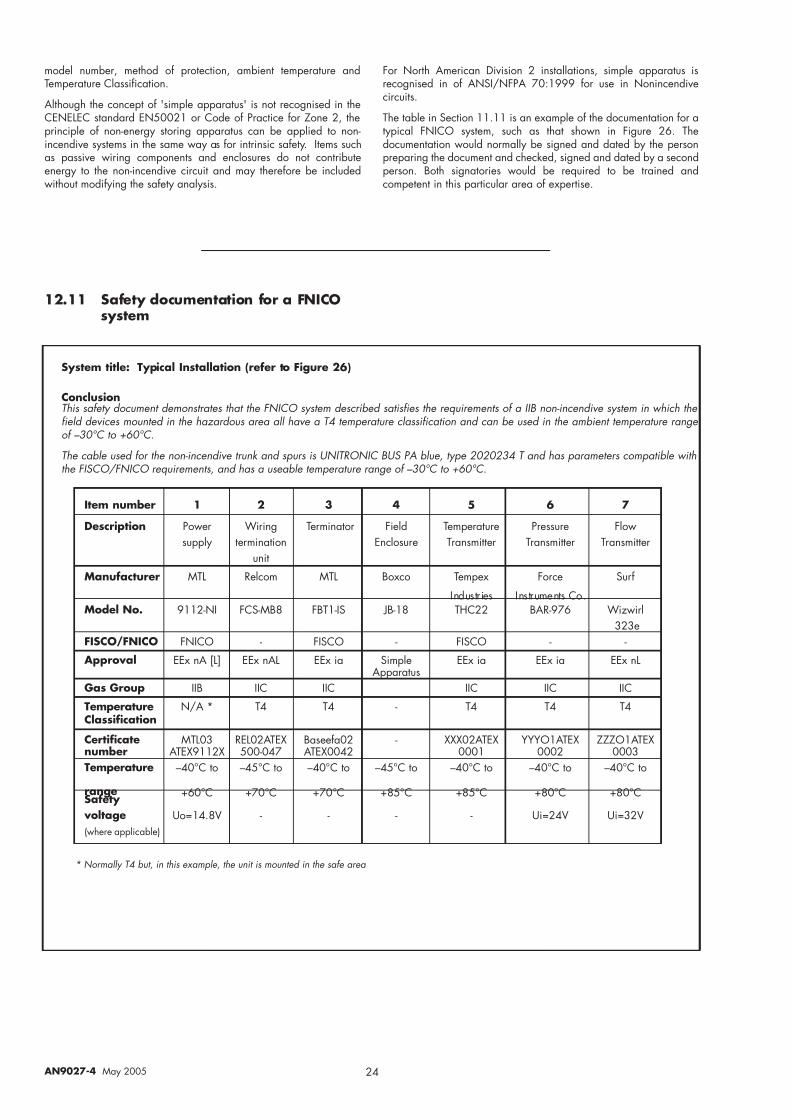
7/27/2019 MTL - FNICO Non-Incendive Fieldbus System.pdf
http://slidepdf.com/reader/full/mtl-fnico-non-incendive-fieldbus-systempdf 28/36
24 AN9027-4 May 2005
model number, method of protection, ambient temperature andTemperature Classification.
Although the concept of 'simple apparatus' is not recognised in theCENELEC standard EN50021 or Code of Practice for Zone 2, theprinciple of non-energy storing apparatus can be applied to non-incendive systems in the same way as for intrinsic safety. Items suchas passive wiring components and enclosures do not contributeenergy to the non-incendive circuit and may therefore be includedwithout modifying the safety analysis.
System title: Typical Installation (refer to Figure 26)
ConclusionThis safety document demonstrates that the FNICO system described satisfies the requirements of a IIB non-incendive system in which the field devices mounted in the hazardous area all have a T4 temperature classification and can be used in the ambient temperature range of –30°C to +60°C.
The cable used for the non-incendive trunk and spurs is UNITRONIC BUS PA blue, type 2020234 T and has parameters compatible withthe FISCO/FNICO requirements, and has a useable temperature range of –30°C to +60°C.
Item number 1 2 3 4 5 6 7
Description Power Wiring Terminator Field Temperature Pressure Flowsupply termination Enclosure Transmitter Transmitter Transmitter
unit
Manufacturer MTL Relcom MTL Boxco Tempex Force Surf
Industries Instruments Co.Model No. 9112-NI FCS-MB8 FBT1-IS JB-18 THC22 BAR-976 Wizwirl
323eFISCO/FNICO FNICO - FISCO - FISCO - -
Approval EEx nA [L] EEx nAL EEx ia Simple EEx ia EEx ia EEx nLApparatus
Gas Group IIB IIC IIC IIC IIC IIC
Temperature N/A * T4 T4 - T4 T4 T4Classification
Certificate MTL03 REL02ATEX Baseefa02 - XXX02ATEX YYYO1ATEX ZZZO1ATEXnumber ATEX9112X 500-047 ATEX0042 0001 0002 0003Temperature –40°C to –45°C to –40°C to –45°C to –40°C to –40°C to –40°C to
range +60°C +70°C +70°C +85°C +85°C +80°C +80°CSafety
voltage Uo=14.8V - - - - Ui=24V Ui=32V(where applicable)
* Normally T4 but, in this example, the unit is mounted in the safe area
For North American Division 2 installations, simple apparatus isrecognised in of ANSI/NFPA 70:1999 for use in Nonincendivecircuits.
The table in Section 11.11 is an example of the documentation for atypical FNICO system, such as that shown in Figure 26. Thedocumentation would normally be signed and dated by the personpreparing the document and checked, signed and dated by a secondperson. Both signatories would be required to be trained andcompetent in this particular area of expertise.
12.11 Safety documentation for a FNICOsystem

7/27/2019 MTL - FNICO Non-Incendive Fieldbus System.pdf
http://slidepdf.com/reader/full/mtl-fnico-non-incendive-fieldbus-systempdf 29/36
25 AN9027-4 May 2005
13 APPENDIX I : SIMPLE APPARATUS AND THE ATEX DIRECTIVE
13.1 Introduction
Simple apparatus has been in use as a valuable part of intrinsicallysafe systems for at least forty years, and the use of this apparatus hasto be re-assessed with the introduction of the two ATEX directives. Thesituation was explored in November 2000 at a meeting of theCENELEC sub-committee SC31-3 and the relevant technical advisorto the Brussels Directorate (Noel O'Riordan) and a statement whichamplified the guidance given to the same committee in October 1999was agreed. These two statements remain the accepted interpretationof the directive.
The original guidance was:
"’Simple apparatus’ will use the phrase from the directive ‘is notcapable of causing an explosion through its own potential sourceof ignition’ thus indicating but not stating that certification to theATEX Directive is not required. That simple apparatus need not bemarked in accordance with Clause 27 of EN 50014: 1997 willbe stated."
The final agreed interpretation was:
"Simple apparatus is considered not to require certification by anotified body .The responsibility for compliance with the relevantparts of the standard rests with the persons claiming compliance,who may be a manufacturer or user. Certification to the ATEXDirective is not required because of the low levels of energy,which are added to the intrinsically safe circuit by this apparatus.Simple apparatus is required to be clearly identified when it isinstalled.
The intention is that simple apparatus is confined to pieces of apparatus which are fundamentally simple. Their safety should bereadily verifiable by visual inspection and reference to availabledata by a competent engineer.
Where a manufacturer considers that certification by a notifiedbody is desirable then this is permitted. In these circumstances, theapparatus shall be certified in the same manner as more complex
apparatus in accordance with EN 50020 and the ESRs of theATEX Directive and be marked accordingly."
The intention of these two statements has been carried through intothe apparatus and system standards, and are the acceptedinterpretation of the ATEX directive on this subject.
13.2 Standards
The most recent apparatus standard is the CENELEC standardEN50020: 2002, which details the requirements of simple apparatusin clause 5.4. This clause is reproduced in full in Appendix II but thecomplete standard needs to be consulted for comprehensiveunderstanding because of the numerous cross references. The onlydifference from the IEC requirement in IEC60079-11 is that the clauserequiring compliance with the Category 1 standards has been added.
The new IEC/ CENELEC standard IEC 60079-25 was published earlyin 2005; the system standard is not directly relevant to the ATEXapparatus directive, but is utilised when producing documentation forthe risk analysis required by the user directive. The system standarddoes not make any specific reference to the inclusion of simpleapparatus but it is necessary to include the known inductive andcapacitive parameters (as indicated in clause 5.4b) of EN 50020) inthe assessment of the system. In the specific case of a FISCO system,the simple apparatus should have an inductance not greater than10µH and a capacitance not greater than 5nF, and can then beregarded in the same way as any field device. The 1.5V, 100mAand 25mW limitation is normally considered to apply to the totalcapability of all the simple apparatus within a single system.Apparatus conforming to these limitations can be added to an
intrinsically safe system without the necessity to reconfirm the safetyanalysis of the system. The system standard does confirm therequirement to clearly identify the simple apparatus and suggests thatthe minimum requirement is 'a traceable plant identification label'
13.3 Conclusion
The continued use of simple apparatus in intrinsically safe circuits iscompatible with both ATEX directives and the relevant Brusselsdirectorate has confirmed this. The accepted current practice remainsunchanged
Note: The USA still uses the older definition of simple apparatus withthe '1.2V, 100mA, 25mW and 20µ J' limitations. This makes verylittle practical difference but has to be taken into account if a system
is being designed for world-wide use.
14 APPENDIX II :EXTRACT FROM BS EN 50020:2002
“ 5.4 Simple apparatus
The following apparatus shall be considered to be simple apparatus:
a) passive components, for example switches, junction boxes, resistors
and simple semiconductor devices
b) sources of stores energy with well-defined parameters, for example
capacitors or inductors, whose values shall be considered when
determining the overall safety of the system;
c) sources of generated energy, for example thermocouples and photocells, which do not generate more than 1,5V, 100mA and
25mW. Any inductance or capacitance present in these sources of
energy shall be considered as in b).
Simple apparatus shall conform to all relevant requirements of this
standard but is not considered to contain a potential source of ignition
capable of causing an explosion and need not be marked in accordance
with clause 12. In particular, the following aspects shall always be
considered:
a) simple apparatus shall not achieve safety by the inclusion of voltage
and/or current-limiting and/or suppression devices;
b) simple apparatus shall not contain any means of increasing the
available voltage or current, for example circuits for the generation
of ancillary power supplies;
c) where it is necessary that the simple apparatus maintains the
integrity of the isolation from earth of the intrinsically safe circuit,
it shall be capable of withstanding the test voltage to earth in
accordance with 6.4.12. Its terminals shall conform to 6.3.1;
d) non-metallic enclosures and enclosures containing light metals
when located in the hazardous area shall conform to 7.3 and 8.1 of
EN 50014;
e) when simple apparatus is located in the hazardous area, it shall be
temperature classified. When used in an intrinsically safe circuit
within their normal rating and at a maximum ambient temperature
of 40°C, switches, plugs, sockets and terminals can be allocated a
T6 temperature classification for Group II applications. Other types
of simple apparatus shall be temperature classified in accordancewith clauses 4 and 6 of this standard;
f) where simple apparatus is to be located such that Category 1 G or
M1 equipment is normally required, then the apparatus shall also
comply with the additional requirements of EN 50284 or EN 50303
as applicable.
Where simple apparatus forms a part of an apparatus containing other
electrical circuits, then the combination of apparatus shall be considered as
a whole.
NOTE Sensors, which utilise catalytic reaction or other electro-chemical
mechanisms, are not normally simple apparatus. Specialist advice on their
application should be sought.”

7/27/2019 MTL - FNICO Non-Incendive Fieldbus System.pdf
http://slidepdf.com/reader/full/mtl-fnico-non-incendive-fieldbus-systempdf 30/36

7/27/2019 MTL - FNICO Non-Incendive Fieldbus System.pdf
http://slidepdf.com/reader/full/mtl-fnico-non-incendive-fieldbus-systempdf 31/36
27 AN9027-4 May 2005
H a z a r d o u s ( C l a s s i f i e d ) L o c a t i o n s :
C
l a s s I , D i v 2 , G r o u p s A , B , C a n d D
C l a s s I I , D i v 2 , G r o u p s E , F a n d G
U n c l a s s i f i e d L o c a t i o n o r H a z a r d o u s
( C l a s s i f i e d ) L o c a t i o n :
C
l a s s I , D i v 2 , G r o u p s A , B , C a n d D
F M a p
p r o v e d I n t r i n s i c a l l y S a f e A p p a r a t u s o r
F M a p
p r o v e d F I S C O a p p a r a t u s o r
F M a p
p r o v e d F N I C O a p p a r a t u s o r
F M a p
p r o v e d n o n - i n c e n d i v e a p p a r a t u s
( N o t e s
2 . 0 , 3 . 0 , 4 . 0 )
U n c l a s s i f i e d L o c a t i o n
U n s p e c i f i e d C o n t r o l
E q u i p m e n t
( N o t e 4 . 2 )
9 1 1 1 - N I
F N I C O P o w e r S u p p l y
N o t e 4 . 6
A n y F M a p p r o v e d
T e r m i n a t o r
( N o t e 1 . 2 )
H a z a r d o u s ( C l a s s i f i e d ) L
o c a t i o n s :
C l a s s I , Z o n e 2 , G r o u p s I I C , I I B , I I A
U n c l a s s i f i e d L o c a t i o n o r H a z a r d o u s
( C l a s s i f i e d ) L o c a t i o n :
C l a s s I , Z o n e 2 , G r o u p s I I C , I I B , I I A
F M a p p r o v e d I n t r i n s i c a l l y S a f e
A p p a r a t u s o r
F M a p p r o v e d F I S C O a p p a r a t u s
o r
F M a p p r o v e d F N I C O a p p a r a t u s
o r
F M a p p r o v e d n o n - i n c e n d i v e a p p a r a t u s
( N o t e s 2 . 0 , 3 . 0 , 4 . 0 )
U n c l a s s i f i e d L o c a t i o n
U n s p e c i f i e d
C o n t r o l
E q u i p m
e n t
( N o t e 4 . 2 )
9 1 1 1 - N I
F N I C O P o w e r S u p p l y
N o t e
4 . 6
A n y F M a p p r o v e d
T e r m i n a t o r
( N o t e 1 . 2 )
9 1 1 1 - N I : Z o
n e C l a s s i f i c a t i o n ; G a s G r o u p s A – D
9 1 1 1 - N I : D i v i s i o n C l a s s i f i c a t i o n ; G a s G r o u p s I I C ,
I I B a n d I I A

7/27/2019 MTL - FNICO Non-Incendive Fieldbus System.pdf
http://slidepdf.com/reader/full/mtl-fnico-non-incendive-fieldbus-systempdf 32/36
28 AN9027-4 May 2005
H a z a r d o u s ( C l a s s i f i e d ) L
o c a t i o n s :
C l a s s I , D i v 2 , G r o u p s C a n d D
C l a s s I I , D i v 2 , G r o u p s E
, F a n d G
U n c l a s s i f i e d L o c a t i o n o r H a z a r d o u s
( C l a s s i f i e d ) L o c a t i o n :
C l a s s I , D i v 2 , G r o u p s C a n d D
F M a p p r o v e d I n t r i n s i c a l l y S a f e
A p p a r a t u s o r
F M a p p r o v e d F I S C O a p p a r a t u s
o r
F M a p p r o v e d F N I C O a p p a r a t u s
o r
F M a p p r o v e d n o n - i n c e n d i v e a p p a r a t u s
( N o t e s 2 . 0 , 3 . 0 , 4 . 0 )
U n c l a s s i f i e d L o c a t i o n
U n s p e c i f i e d
C o n t r o l
E q u i p m
e n t
( N o t e 4 . 2 )
9 1 1 2 - N I
F N I C O P o w e r S u p p l y
N o t e
4 . 6
A n y F M a p p r o v e d
T e r m i n a t o r
( N o t e 1 . 2 )
H a z a r d o u s ( C l a s s i f i e d ) L o c a t i o n s :
C l a s s I , Z o n e 2 , G r o u p s I I B a n d I I A
U
n c l a s s i f i e d L o c a t i o n o r H a z a r d o u s
( C l a s s i f i e d ) L o c a t i o n :
C
l a s s I , Z o n e 2 , G r o u p s I I B a n d I I A
F M a p
p r o v e d I n t r i n s i c a l l y S a f e A p p a r a t u s o r
F M a p
p r o v e d F I S C O a p p a r a t u s o r
F M a p
p r o v e d F N I C O a p p a r a t u s o r
F M a p
p r o v e d n o n - i n c e n d i v e a p p a r a t u s
( N o t e s
2 . 0 , 3 . 0 , 4 . 0 )
U n c l a s s i f i e d L o c a t i o n
U n s p e c i f i e d C o n t r o l
E q u i p m e n t
( N o t e 4 . 2 )
9 1 1 2 - N I
F N I C O P o w e r S u p p l y
N o t e 4 . 6
A n y F M a p p r o v e d
T e r m i n a t o r
( N o t e 1 . 2 )
9 1 1 2 - N I : Z o n e C l a s s i f i c a t i o n
; G a s G r o u p s C ,
D
9 1 1 2 - N I : D i v i s i o n C l a s s i f i c a t i o n ; G a s G r o u p s I I B
a n d I I A

7/27/2019 MTL - FNICO Non-Incendive Fieldbus System.pdf
http://slidepdf.com/reader/full/mtl-fnico-non-incendive-fieldbus-systempdf 33/36
29 AN9027-4 May 2005

7/27/2019 MTL - FNICO Non-Incendive Fieldbus System.pdf
http://slidepdf.com/reader/full/mtl-fnico-non-incendive-fieldbus-systempdf 34/36
30 AN9027-4 May 2005

7/27/2019 MTL - FNICO Non-Incendive Fieldbus System.pdf
http://slidepdf.com/reader/full/mtl-fnico-non-incendive-fieldbus-systempdf 35/36
31 AN9027-4 May 2005

7/27/2019 MTL - FNICO Non-Incendive Fieldbus System.pdf
http://slidepdf.com/reader/full/mtl-fnico-non-incendive-fieldbus-systempdf 36/36
MTL Instruments Pty Limited9 Vinnicombe DrivePO Box 1441, Canning ValePerth, WA 6155AustraliaTel: +61 (0)8 9455 2994 Fax: +61 (0)8 9455 2805E-mail: [email protected]
MTL Canada Safety Instrumentation511 Edinburgh Road South, Ste 202Guelph, Ontario N1G 4S5CanadaTel: +1 519 821 5775 Fax: +1 519 821 1753E-mail: [email protected]
MTL Instruments PteRoom 901, The GatewayNo 10 Yabao Road, Chaoyang DistrictBeijing 100020ChinaTel: +86 010 8562 5718/5720/5721 Fax: +86 010 8562 5725E-mail: [email protected]
MTL Instruments sarlBâtiment 4,
Parc d’Activités de Limonest1 rue des Vergers69760 LimonestFranceTel: +33 (0)4 78 64 98 32 Fax: +33 (0)4 78 35 79 41E-mail: [email protected]
MTL Instruments GmbHAn der Gümpgesbrücke 17D-41564 KaarstGermanyTel: +49 (0)2131 718930 Fax: +49 (0)2131 7189333E-mail: [email protected]
MTL India Pvt. LimitedNo. 36, Nehru Street
Off Old Mahabalipuram RoadSholinganallurChennai - 600 119IndiaTel: + 91 (0)44 24501660/24501857 Fax: + 91 (0)44 24501463E-mail: [email protected]
MTL Italia srlVia Fosse Ardeatine, 4I - 20092 Cinisello Balsamo MIItalyTel: +39 (0)2 61802011 Fax: +39 (0)2 61294560E-mail: [email protected]
MTL Instruments KK
3rd Floor, Gotanda Masujima Building1-8-13 Higashi-Gotanda, Shinagawa-KuTokyo 141-0022 JapanTel: +81 (0)3 5420 1281 Fax: +81 (0)3 5420 2405E-mail: [email protected]
MTL Instruments BV de Houtakker 33, 6681 CW BemmelThe NetherlandsTel: +31 (0)481 450250 Fax: +31 (0)481 450260E-mail: [email protected]
MTL Instruments Pte Limited128 Joo Seng Road#07-00 DP Computers BuildingSingapore 368356
Tel: +65 6 487 7887 Fax: +65 6 487 7997E-mail: [email protected]
MTL InstrumentsPO Box 53234, 8th FloorWest Tower, Abu Dhabi at the Trade CentreAbu Dhabi, UAETel: +971 2 645 2620 Fax: +971 2 645 2630E-mail: [email protected]
MTL Instruments LimitedPower Court, Luton, BedfordshireEngland LU1 3JJTel: +44 (0)1582 723633 Fax: ++44 (0)1582 422283E-mail: [email protected]
MTL Incorporated9 Merrill Industrial Drive, Hampton NH 03842USATel: +1 800 835 7075 Fax: +1 603 926 1899E-mail: [email protected]