mt6601 bluetooth debug sop (version 5.4) -...
TRANSCRIPT

MediaTek ConfidentialSubject to Change without Notice
WCP_SAWCP_SA
2007.11.122007.11.12
MT6601 Bluetooth Debug SOP (Version 5.4)

MediaTek ConfidentialSubject to Change without Notice
MT6601 HW Debug ProcedureMT6601 HW Debug Procedure
4-1.Check mcu\make file
4-2.Setup “btmtk_config.c”
4-3.Setup GPIO Setting in“gpio_drv.c” or “codegen.dws”
1.Verify voltage level of BT power includes 2.8V & 1.8V
2.Check Connection between BB&BT(1) UART TXD & RXD(2) GPIO_BT_reset & GPIO_BT_32kHz(3) EINT_BT(4) PCM pins
3.Check Reference Frequency & Clock Setting(BT_UCTS1 & BT_URTS1)
4.Check BT HW Configuration File
5.BT Function Power on !
4-4.Setup EINT_BT in“eint_def.c” or “codegen.dws”

MediaTek ConfidentialSubject to Change without Notice
1.Verify voltage level of BT power1.Verify voltage level of BT power
BT_PWR=2.8V.It should be providedby external LDO orMT6318.Vmc
+1V8 is generatedby MT6601 internalLDO
Remark: You can find the detailed schematic from “MT6601 reference design”

MediaTek ConfidentialSubject to Change without Notice
2.Check connection between BB&BT2.Check connection between BB&BT
To BB GPIO_RESET or GPO_RESET
To BB GPIO_32kHZ or GPO_32kHz
To BB EINT0~EINT7
To BB UART3_RXTo BB UART3_TX
To BB PCMCLKTo BB PCMSYNCTo BB PCMINTo BB PCMOUT
Remark: You can find the detailed schematic from “MT6601 reference design”
Don’t use UART2!

MediaTek ConfidentialSubject to Change without Notice
3. Check reference freq. & clock setting3. Check reference freq. & clock setting● URTS, UCTS voltage level configure the reference clock frequency.
● C22, C23 and R5 loop filter value design the reference clock frequency.
UCTS1 & URTS1 is internal pull-high

MediaTek ConfidentialSubject to Change without Notice
● File Location– \mcu\make\Project_Name.mak– BLUETOOTH_SUPPORT = BTMTK_MT6601 # BTMTK, NONE, BTVCSR_HP or
BTVCSR_HCI_BCHS or BTMTK or BTMTK_MT6601
● Notes– BTMTK_MT6601: MTK BT IC MT6601 default setting. (Optimized!)– None: No support BT.– BTVCSR_HP: Support CSR BT Handphone Solution. (Phase Out!)– BTVCSR_HCI_BCHS: Support CSR BT BCHS Solution. (Phase Out!)– BTMTK: Support MTK &RFMD BT Solution.
● Example– BLUETOOTH_SUPPORT = BTMTK_MT6601 # BTMTK, NONE, BTVCSR_HP or
BTVCSR_HCI_BCHS or BTMTK or BTMTK_MT6601
4.Check BT HW configuration file4.Check BT HW configuration file(4.1 (4.1 -- make file)make file)

MediaTek ConfidentialSubject to Change without Notice
● File Location– mcu\custom\drv\bluetooth\XXX_BB\btmtk_config.c
● Notes– GPIO_power_on: it should be set to 0xFF if PMIC(MT6318) is used (Vmc default)– cts3 & rts3 pin: default UART configuration is non-flow control, so it have to be set 0xFF
● Example#ifdef __BTMODULE_MT6601__/*GORM*//*GORM*/ const unsigned char bt_gpio_setting[16] =/*GORM*/ { 1, 1, // GPIO_power_pin, pol : (if use GPO, please plus 100)/*GORM*/ 21, 1, // GPIO_BT_wakeup_pin, pol : (if use GPO, please plus 100)/*GORM*/ 3, 1, // EINT_BT , pol/*GORM*/ 39, 40, // rxd3, txd3 : GPIO number in baseband/*GORM*/ 0xFF, 0xFF, // cts3, rts3 : GPIO number in baseband/*GORM*/ 18, 3, // 32kHz_pin, 32kHz mode in GPIO/GPO: (if use GPO, please plus 100)/*GORM*/ 49, 53, // PCM clk, PCM sync/*GORM*/ 50, 51 // PCM data output, PCM data input/*GORM*/ };/*GORM*/#endif
4.Check BT HW configuration file4.Check BT HW configuration file(4.2 (4.2 -- btmtk_config.cbtmtk_config.c file, before W0724 file, before W0724 s/ws/w))
Using GPO to be32kHz shouldpatch ID:MAUI_00396490
No need to change! Using EINT4~7should patch ID:MAUI_00376083

MediaTek ConfidentialSubject to Change without Notice
4.Check BT HW configuration file 4.Check BT HW configuration file (4.3 (4.3 -- goio_drv.cgoio_drv.c file, before W0724 file, before W0724 s/ws/w) ) [Case of non[Case of non--using using DRV_ToolDRV_Tool]]
● File Location– mcu\custom\drv\misc_drv\XXX_BB\gpio_drv.c
● Notes– Please set all interface pins (power_pin / wakeup_pin / 32kHz / UART / PCM) to be(1)Default mode = GPIO mode(2)Default direction = Output(3)Disable Pull up/down(4)Set Output level = 0
● Assign following variables to applicable GPIO– gpio_bt_power_pin;– gpio_bt_wakeup_pin;– gpio_bt_32k_pin;– gpio_bt_utxd3_pin;– gpio_bt_urxd3_pin;– gpio_bt_ucts3_pin;– gpio_bt_urts3_pin;– gpio_bt_pcmclk_pin;– gpio_bt_pcmsync_pin;– gpio_bt_pcmin_pin;– gpio_bt_pcmout_pin;
Important !!

MediaTek ConfidentialSubject to Change without Notice
● Location- \mcu\custom\drv\misc_drv\XXX_BB\codegen\codegen.dws
● Confirm “DRV_CUSTOM_TOOL_SUPPORT = TRUE” in make file first!
● Assign following variables to applicable GPIO– gpio_bt_power_pin;– gpio_bt_wakeup_pin;– gpio_bt_32k_pin;– gpio_bt_utxd3_pin;– gpio_bt_urxd3_pin;– gpio_bt_ucts3_pin;– gpio_bt_urts3_pin;– gpio_bt_pcmclk_pin;– gpio_bt_pcmsync_pin;– gpio_bt_pcmin_pin;– gpio_bt_pcmout_pin;
4.Check BT HW configuration file4.Check BT HW configuration file(4.3 (4.3 -- codegen.dwscodegen.dws (1/3),before W0724 (1/3),before W0724 s/ws/w )) [Case of using [Case of using DRV_ToolDRV_Tool]]

MediaTek ConfidentialSubject to Change without Notice
● For example of “Assign following variables to applicable GPIO”– gpio_bt_power_pin; - Ex: Use GPIO1 to be bt_power_pin signal
– gpio_bt_wakeup_pin; - Ex: Use GPIO21 to be bt_wakeup_pin signal
– gpio_bt_32k_pin; - Ex: Use GPIO18 to be bt_32kHZ
● Notes: Please set all interface pins (power_pin / wakeup_pin / 32kHz / UART / PCM) to be(1)Default mode = GPIO mode(2)Default direction = Output(3)Disable Pull up/down(4)Set Output level = 0 (codegen.dws cannot set the default output level=0, please
modify this in your gpio_drv.c)
4.Check BT HW configuration file 4.Check BT HW configuration file (4.3 (4.3 -- codegen.dwscodegen.dws (2/3), before W0724 (2/3), before W0724 s/ws/w)) [Case of using [Case of using DRV_ToolDRV_Tool]]

MediaTek ConfidentialSubject to Change without Notice
● For example of “Assign following variables to applicable GPIO”– gpio_bt_utxd3_pin; - Ex: Use GPIO40 to be UTXD3– gpio_bt_urxd3_pin; - Ex: Use GPIO39 to be URXD3– gpio_bt_ucts3_pin; - Ex: Use GPIO37 to be UCTS3– gpio_bt_urts3_pin; - Ex: Use GPIO38 to be URTS3
– gpio_bt_pcmclk_pin; - Ex: Use GPIO49 to be PCM_CLK– gpio_bt_pcmsync_pin; - Ex: Use GPIO53 to be PCM_Sync– gpio_bt_pcmin_pin; - Ex: Use GPIO51 to be PCM_IN– gpio_bt_pcmout_pin; - Ex: Use GPIO50 to be PCM_Out
4.Check BT HW configuration file 4.Check BT HW configuration file (4.3 (4.3 -- codegen.dwscodegen.dws (3/3), before W0724 (3/3), before W0724 s/ws/w)) [Case of using [Case of using DRV_ToolDRV_Tool]]
● Notes: Please set all interface pins (power_pin / wakeup_pin / 32kHz / UART / PCM) to be(1)Default mode = GPIO mode(2)Default direction = Output(3)Disable Pull up/down(4)Set Output level = 0 (codegen.dws cannot set the default output level=0, please
modify this in your gpio_drv.c)

MediaTek ConfidentialSubject to Change without Notice
● For example of “setup EINT_BT”– EINT_BT - Ex: Use EINT0~3 to be BT_EINT=>You just need to setup BT_EINT in codegen.dws “EINT setting” page
– EINT_BT - Ex: Use EINT4~7 to be BT_EINT=>For example: EINT4 is MUX with GPIO36 in MT6226/MT6226M/MT6227, so please set GPIO36 to be Mode 3(EINT4 mode)
4.Check BT HW configuration file 4.Check BT HW configuration file (4.4 (4.4 -- setup EINT_BT) setup EINT_BT) [Case of using [Case of using DRV_ToolDRV_Tool]]

MediaTek ConfidentialSubject to Change without Notice
● Before W0724 s/w– No matter you enable drv_tool or not, you should configure btmtk_config.c
● After W0724 s/w– If you enable drv_tool, you don’t need to configure btmtk_config.c
– If the Driver Customization Tool is used gpio_bt_power_pin for power on pin (Notice!! SHOULD NOT assign this variable if the PMIC(MT6318) is used instead of a GPIO pin for controlling a LDO)
gpio_bt_reset_pin for reset pin (Notice!! This variable name has been changed after 06BW0724MP /07AW0724MP, the old name is gpio_bt_wakeup_pin)
gpio_bt_utxd3_pin / gpio_bt_urxd3_pin for UART (Notice!! DON’T NEED TO assign gpio_bt_ucts3_pin /gpio_bt_urts3_pin if UART hardware flow control is not used)
– If the Driver Customization Tool is not used No difference with (before W0724 s/w)
Comparison between (before W0724 Comparison between (before W0724 s/ws/w) & (after W0724 ) & (after W0724 s/ws/w) )

MediaTek ConfidentialSubject to Change without Notice
Issue Case Study Issue Case Study -- 11[Issue description] A2DP distance is too short
[Possible Rootcause]1.If BT stereo headphone support only SBC (Don’t support MP3 bit stream), you
can adjust bitrate to get the acceptable distance.
*Remark: [Bitrate increase -> A2DP Quality increase but Distance decrease]*Remark: [Bitrate decrease -> A2DP Quality decrease but Distance increase]
2.Bad BT wireless performance : bad TX power or bad antenna matching
[Solution]1. As our experiement, the A2DP distance can reach 8~10M in bitrate=211.
The default bitrate setting =345, So please optimize the bitrate.
You can adjust bitrate in path: \\mcu\custom\common\bt_common_config.ckal_uint16 BT_A2DP_MAX_BIT_RATE = 211; // recommand value=211
2.Please check BT wireless performance (Refer to Appendix 1~4)

MediaTek ConfidentialSubject to Change without Notice
Issue Case Study Issue Case Study -- 22[Issue description] In BT talking mode, BT headphone can hear some bo-bo noise in long distance.
[Possible Rootcause]1.Due to BT speech adopt HV3 packet, it doesn’t have the protection & re-send
mechanism, so BT headphone can hear some bo-bo noise in long distance.It’s the normal behavior in BT talking mode, you can benchmark the speechquality with other BT solution phone.
2.Bad BT wireless performance : bad TX power or bad antenna matching
[Solution]1.Due to speech quality will be strongly related to wireless performance, so please
check wireless performance first.
2.Please check BT wireless performance (Refer to Appendix 1~4)

MediaTek ConfidentialSubject to Change without Notice
Power Control
PLLSynthesizer
Internal50 OhmMatch
NetworkGFSK
Modem
LNAADC
ADC
DAC
DAC
Appendix1 : How to layout for BT TX Power more than 0dBm?Appendix1 : How to layout for BT TX Power more than 0dBm?
RFIO
IDAC
TX_BIAS
1.8V
L
1.2nHC 8pFL
MT6601 RADIO PARTMT6601 RADIO PART
• Keep LC close to Pin TX_BIAS (B4 pin)• Keep TX bias trace width more than 12mil .• Keep trace between pin TX_BIAS(B4 pin) and pin VDD_BB(C1 pin) as short as possible.• Put more than 4 ground via in analog ground.
ANALOG GROUND
PA

MediaTek ConfidentialSubject to Change without Notice
● TX BIAS L Dominates BT TX Power.● Based on MTK Layout Suggestion, typically customer can set L=1.2nH for Max.
TX power.
TX_BIAS L VS.TX POEWER
-14
-12
-10
-8
-6
-4
-2
0
2
0 1 1.1 1.2 1.3 1.5 1.6 1.8 2 2.2 2.4 2.7 3
TX_BIAS Inductor(nH)
TX P
OW
ER(d
Bm)
CH0
CH39
CH78
Appendix2 : The Relation between TX_BIAS L & BT TX Power Appendix2 : The Relation between TX_BIAS L & BT TX Power
L=1.2nH
High impedance of TX bias & few ground via will cause narrow TX power range

MediaTek ConfidentialSubject to Change without Notice
● Step 1: BT DUT Connect CMU or spectrum.PS: CMU200:Menu select Basic function RF Spectrum .
● Step 2: Use Meta(after ver.5.3.4.2) and Fine tune TX power.PS:Meta tool MediaTek BT tools RF test & setting as follow.
● Fine tune Tx_bias L:1.0nH~1.5nH.C:6~12pF for peak power.
Appendix3 : How to fine tune BT TX power Appendix3 : How to fine tune BT TX power
1.Setup BT TX CH
2.Setup Packet type, length
3.Start TX test
Note:1.BT CH0~78:2402+nMhz.2.Right now we suggest customer use Murata LQPM15 Series Inductor .3.Typical TX power is -0.5dBm.

MediaTek ConfidentialSubject to Change without Notice
Appendix4 : Layout Design Note (1) Appendix4 : Layout Design Note (1)
● RF Path keep as short as possible.RF_IO on the MT6601 is single-ended. The RF_IO port is internally matched to 50ohm.Customer also can add LC component for matching to avoid PCB impedance deviation.U4 is a 2.4GHz band-pass filter and provides good isolation to reject large interference from other radio systems.
● Keep analog LC component close to IC as possible& remove digital signal line under analog LC component.
a. CHG_PUMP (Pin F1):C20,R1&C21 close to IC pin F1 as possible. Ground also closed to IC ground pad.
b. VREF_CAP (Pin B1,B2):C24,C25&L25 close to IC pin B1&B2.Ground also closed to IC ground pad.
c. MCG_CHG (Pin B5) :C22,C23&R39 close to IC pin B5.d. TX_OUT (Pin B4):L2,C17close to IC pin B4. Ground also closed
to IC ground pad. The trace width should be morethan 10 mils.

MediaTek ConfidentialSubject to Change without Notice
Appendix4 : Layout Design Note (2)Appendix4 : Layout Design Note (2)
● Separate Analog ground & digital groundMt6601 schematic circuit incorporates two grounds: analog ground and digital ground. The analog and digital ground pins are grouped together to simplify the ground split in the PCB layout.Analog Ground: GND_RX (B3), GND_PREAMP (D4), GND_PREAMP_BIAS (E4),
GND_TX_BAL (D5), GND_MCG (C5), GND_VCO (F2), GND_VCODIG (E2), GND_BB (C2).
Digital Ground: GND_SUB_CM (E8), GND_SUB_CM (E6), VSSP (G1), VSSP (J9), VSSP (C7), GND_IO (F5), GND_TX_DATA (F4), GND_P0 (E5), GND_P1 (E6), GND_SUB_CM (C6).
● Add more than 5 ground Via in analog ground.( Main ground via.)
● Enclose 32K signal line with ground.

MediaTek ConfidentialSubject to Change without Notice
Appendix4 : Layout Design Note (3)Appendix4 : Layout Design Note (3)
● Separate Analog Power Supply RoutingPower supply traces should keep low impedance (line width more than 10 mils) and should be adequately de-coupled. If possible, avoid routing supply lines near the RF port of the near the RF output signal lines. VDD_1V8 should go from pin C1 directly to C4.From C4, VDD_1V8 should be separately to pin A2, A4, A5, F1, D2 and other VDD_1V8 power supplies.C7 should be close to pin E1 to avoid DH1 deviation .

MediaTek ConfidentialSubject to Change without Notice
Issue Case Study Issue Case Study -- 33[Issue description] BT active is unstable. - Sometimes BT active successfully, sometimes BT active abortively.- MMI shows “Initializing Bluetooth Now, Wait a Moment!”!
[Possible Rootcause]1. The S/W before W0720 should change the power on sequence.2. Please refer to “Issue Case Study-7”3. Please refer to “Issue Case Study-9”4. Wrong connection between BT UART and GSM BB UART
[Solution]1. Before W0720 S/W version, please ask S/W PM to get patch ID: MAUI_00396490
Besides, you can find the right power on sequence in next page.2. Please refer to “Issue Case Study-7”3. Please let MT6601 D6 pin floating.4. BT_UART_TX should connect to GSM_BB_UART_RX
BT_UART_RX should connect to GSM_BB_UART_TX

MediaTek ConfidentialSubject to Change without Notice
MT6601 Power On Seq.MT6601 Power On Seq.
CH1 = BT_RX
CH2 = BT_TX
CH3 = BT_RESET
CH4 = BT_PWR
Power On Sequence:(0)Set GPIO as UART mode & BT_PWR ON(1)Delay 200ms -> Set BT_Reset=High(2)Delay 200ms -> Set BT_Reset=Low (3)Delay 100ms -> Set GPIO pins as PCM /32kHz
& power on BB UART3(4)Delay 200ms -> Set BT_Reset=High(5)Delay 100ms -> BB start to communicate with BT
(MT6226B+MT6601)BT active will be always successful!
(0)
(2)(1)
(3)
(4)
(5)
(0)

MediaTek ConfidentialSubject to Change without Notice
Issue Case Study Issue Case Study -- 44[Issue description] In BT power off, there will be about 10mA current leakage in BT interface.
[Rootcause]BT interface pins (including power_pin / wakeup_pin /32kHz / UART / PCM) should set to “default GPIO mode” !
[Solution]Notes: Please set all interface pins (power_pin / wakeup_pin / 32kHz / UART / PCM) to be
(1)Default mode = GPIO mode(2)Default direction = Output(3)Disable Pull up/down(4)Set Output level = 0 (codegen.dws cannot set the default output level=0, please
modify this in your gpio_drv.c)

MediaTek ConfidentialSubject to Change without Notice
Issue Case Study Issue Case Study -- 55[Issue description] In BT power on, there will be about 8mA current leakage in PCM_CLK pin.
[Rootcause]The default PCM_CLK in BT side and GSM side are both output mode.MTK already changed the default PCM_CLK in BT side to be input mode.
[Solution]Before W0720 S/W version, please ask S/W PM to get patch ID: MAUI_00380152

MediaTek ConfidentialSubject to Change without Notice
Issue Case Study Issue Case Study -- 66[Issue description] When BT Crystal=26Mhz. In BT power on, there will be about 14mA current leakage from BT_PWR to BT_URTS1 pin.
[Rootcause]When BT Crystal use 26MHz, BT_CTS1 and BT_RTS1 should pull-high to BT_PWR.But BT_RTS1 pin will configure to UART RTS mode (Keep low level) after BT power on, so there will be about 14mA current leakage from BT_PWR to BT_URTS1 pin.
[Solution]1.Before W0728 S/W version, please ask S/W PM to get patch ID: MAUI_004067492.Change SCH as following:
Leakage path
MediaTek ConfidentialSubject to Change without Notice
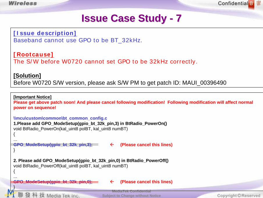
Issue Case Study Issue Case Study -- 77[Issue description] Baseband cannot use GPO to be BT_32kHz.
[Rootcause]The S/W before W0720 cannot set GPO to be 32kHz correctly.
[Solution]Before W0720 S/W version, please ask S/W PM to get patch ID: MAUI_00396490
[Important Notice]Please get above patch soon! And please cancel following modification! Following modification will affect normal power on sequence!
\\mcu\custom\common\bt_common_config.c1.Please add GPO_ModeSetup(gpio_bt_32k_pin,3) in BtRadio_PowerOn() void BtRadio_PowerOn(kal_uint8 polBT, kal_uint8 numBT){...GPO_ModeSetup(gpio_bt_32k_pin,3); (Please cancel this lines)}
2. Please add GPO_ModeSetup(gpio_bt_32k_pin,0) in BtRadio_PowerOff()void BtRadio_PowerOff(kal_uint8 polBT, kal_uint8 numBT){...GPO_ModeSetup(gpio_bt_32k_pin,0); (Please cancel this lines)}

MediaTek ConfidentialSubject to Change without Notice
Issue Case Study Issue Case Study -- 88[Issue description] Baseband cannot use EINT4~7 to be BT_EINT.
[Rootcause]The S/W before W0720 cannot set EINT4~7 to be BT_EINT correctly.
[Solution]Before W0720 S/W version, please ask S/W PM to get patch ID: MAUI_00376083

MediaTek ConfidentialSubject to Change without Notice
Issue Case Study Issue Case Study -- 99[Issue description] (1)BT Active -> (2)Power off phone -> (3)Phone on phone ->(4)Then BT will be power on fail.
[Rootcause]D6 pin is BT hardware reset pin, please keep it floating.
[Solution]Remove R790 resistor. (Like following example)
MediaTek ConfidentialSubject to Change without Notice
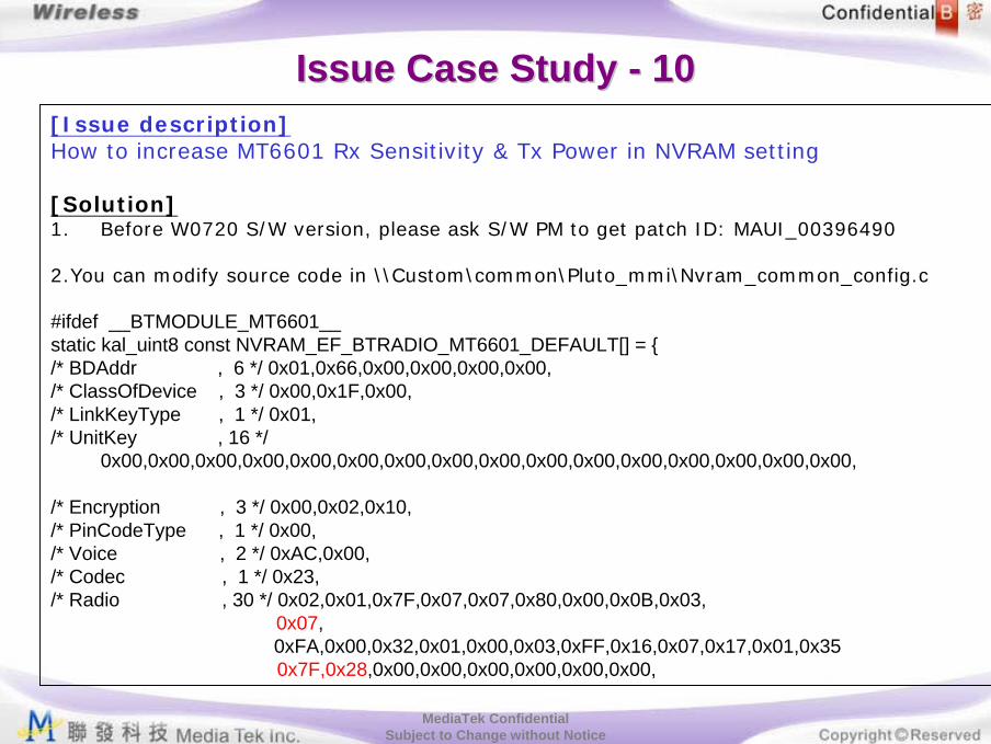
Issue Case Study Issue Case Study -- 1010[Issue description] How to increase MT6601 Rx Sensitivity & Tx Power in NVRAM setting
[Solution]1. Before W0720 S/W version, please ask S/W PM to get patch ID: MAUI_00396490
2.You can modify source code in \\Custom\common\Pluto_mmi\Nvram_common_config.c
#ifdef __BTMODULE_MT6601__static kal_uint8 const NVRAM_EF_BTRADIO_MT6601_DEFAULT[] = {/* BDAddr , 6 */ 0x01,0x66,0x00,0x00,0x00,0x00,/* ClassOfDevice , 3 */ 0x00,0x1F,0x00,/* LinkKeyType , 1 */ 0x01,/* UnitKey , 16 */
0x00,0x00,0x00,0x00,0x00,0x00,0x00,0x00,0x00,0x00,0x00,0x00,0x00,0x00,0x00,0x00,
/* Encryption , 3 */ 0x00,0x02,0x10,/* PinCodeType , 1 */ 0x00,/* Voice , 2 */ 0xAC,0x00,/* Codec , 1 */ 0x23,/* Radio , 30 */ 0x02,0x01,0x7F,0x07,0x07,0x80,0x00,0x0B,0x03,
0x07, 0xFA,0x00,0x32,0x01,0x00,0x03,0xFF,0x16,0x07,0x17,0x01,0x350x7F,0x28,0x00,0x00,0x00,0x00,0x00,0x00,

MediaTek ConfidentialSubject to Change without Notice
Increase MT6601 Rx Sensitivity/Increase MT6601 Rx Sensitivity/TxTx Power in META mode (1/2)Power in META mode (1/2)
0x28
0x7F
0x07Step 1
Step 2
Step 3
Step 4
Issue Case Study Issue Case Study -- 1010

MediaTek ConfidentialSubject to Change without Notice
● Step 1: Select MT6601 LID in NVRAM Editor– Other LID – NVRAM_EF_BTRADIO_MT6601_LID – 1
● Step 2: click Read from NVRAM● Step 3: modify NVRAM
– Radio[9] = 0x07– Radio[22]=0x7F– Radio[23]=0x28
● Step 4: save to NVRAM● Note: Increasing Rx sensitivity/Tx power, increasing power
consumption.
Issue Case Study Issue Case Study -- 1010Increase MT6601 Rx Sensitivity/Increase MT6601 Rx Sensitivity/TxTx Power in META mode (2/2)Power in META mode (2/2)

MediaTek ConfidentialSubject to Change without Notice
Issue Case Study Issue Case Study -- 1111[Issue description]1. Phone ON, then turn on BT2-1. Phone low power H/W shutdown in low Vbat2-2. Power off phone normally. 3. There will be about 30mA current leakage probably.
[Rootcause]There will be one leakage path from BT_UTXD1 to BB_URXD1, so GPIO of LDOenable pin cannot go to low in case of 2-1 & 2-2
[Solution]1. S/W solution
- Before W0728 S/W version, please ask S/W PM to get patch: MAUI_00417495 & MAUI_00418338
- Increase S/W shutdown voltage to decrease H/W shutdown probability
2. H/W solution-Add one diode and pull-up resistor in BT_UTXD1(Like following figure)

MediaTek ConfidentialSubject to Change without Notice
Issue Case Study Issue Case Study -- 1212[Issue description]BT headset volume is not enough (includes uplink & downlink)
[Rootcause]L1audio can adjust the digital gain of baseband, you can find it in "l1audio/am.c
AM_DSP_BluetoothOn()".
But if you're asking for the analog gain modification in the BT headset, L1audio of our S/W cannot control that.
[Solution]L1audio can adjust the digital gain of baseband, you can find it in "l1audio/am.c
AM_DSP_BluetoothOn()".
You just need to change *DP_VOL_OUT_PCM = 0x1000;*DP_VOL_IN_PCM = 0x1000;
0x1000(Hex)= 4096 (Oct) means 0dB - min. gain0x7fff (Hex) =32767(Oct) means 18dB - max. gain
When you set gain=xxxx(Oct), The gain formula is as following:20log(xxxx/4096)= dB.

MediaTek ConfidentialSubject to Change without Notice
Issue Case Study Issue Case Study -- 1313[Issue description]BT will have unexpected disconnection after BT enter sleep mode.
[Rootcause]BT_GPIO_32kHZ cannot use 32kHz with 1.8V Vio power domain.
[Solution]BT_GPIO_32kHz must use 32kHz with 2.8V Vio power domain.
[Don’t choose following BT_GPIO_32kHz if project adopt VDD33_EMI=1.8V]• MT6223:There is no any 32kHz with VDD33_EMI power domain.
• MT6225:GPO1 could be 32kHz in mode 3.GPO2 could be 32kHz in mode 2.The Vio power domain of GPO1 & GPO2 are VDD33_EMI.
• MT6226/MT6226M/MT6227:GPIO41 could be 32kHz in mode 3.GPO4 could be 32kHz in mode 3.The Vio power domain of GPIO41 & GPO4 is VDD33_EMI.
• MT6228/MT6229/MT6230 : GPIO36 could be 32kHZ in mode 3.The Vio power domain of GPIO36 is VDD33_EMI.

MediaTek ConfidentialSubject to Change without Notice
Issue Case Study Issue Case Study -- 1414[Issue description]FTP throughput only has about 30kBPS[Rootcause](1)Put digital signal trace under analog LC component like CHG_PUMP, VREF_CAP, MCG_CHG
& TX bias.(2) 32khz signal line Interference MT6601 analog part.[Solution](1) Check BT layout to avoid Rootcause 1&2.
-Remove digital line under analog LC component.-Enclose 32Khz with ground.
(2) Check FTP through put more than 50 KBPS.
UnitsSuperman29
V3BT dongle
MT6601BT chip
kB60.63Connection-FTP Phone ⇐ PC dongle (Downlink)
kB71.18Connection-FTP Phone ⇒ PC dongle (Uplink)Broadcom
kB62.75Connection-FTP Phone ⇐ PC dongle (Downlink)
kB70.14Connection-FTP Phone ⇒ PC dongle (Uplink)RFMD
kB59.62Connection-FTP Phone ⇐ PC dongle (Downlink)
kB71.54Connection-FTP Phone ⇒ PC dongle (Uplink)CSR