mt60p - capitaldoorworks.com manuals/mt60p.pdf · keep garage door balanced . do not let the garage...
TRANSCRIPT

Owners Copy: Please keep these instructions for future reference
www.chamberlainanz.com
This manual contains IMPORTANT SAFETY information.DO NOT PROCEED WITH THE INSTALLATION BEFORE READING THOROUGHLY.
MT60PSectional and Tilt Garage Door Opener
Installation and Operating Instructions

1
CONTENTS PAGESAFETY INSTRUCTIONS . . . . . . . .1DOOR TYPES . . . . . . . . . . . . . . . . .2TOOLS REQUIRED . . . . . . . . . . . .2HARDWARE PROVIDED . . . . . . .2-3BEFORE YOU BEGIN . . . . . . . . . . .4COMPLETED INSTALLATION . . . .4ASSEMBLY . . . . . . . . . . . . . . . . .4-6INSTALLATION . . . . . . . . . . . . . .7-11ADJUSTMENT . . . . . . . . . . . . .12-13WIRELESS PROGRAMMING .14-15
INSTALL THE PROTECTORSYSTEM (OPTIONAL) . . . . . . . . .13SPECIAL FEATURES . . . . . . . . . .17ACCESSORIES . . . . . . . . . . . . . . .18REPLACEMENT PARTS . . . . .19-20CARE OF YOUR OPENER . . . . . .20MAINTAINING YOUR OPENER . .20TROUBLESHOOTING . . . . . . . . . 21OPERATION OF YOUR OPENER 22SPECIFICATIONS . . . . . . . . . . . . .22WARRANTY . . . . . . . . . . . . . . . . .23
Warning: If your garage has no service entrance door, a CM1702 outside quick release must be installed.This accessory allows manual operation of the garage door from outside in case of power failure.
The Protector System TM must be used for allinstallations where the closing force asmeasured on the bottom of the door is over400N (40kgf). Excessive force will interfere with theproper operation of the Safety Reverse System ordamage the garage door.
After installation, ensure that the parts of thedoor do not extend over public footpaths orroads.
Install the wireless wall control (or any additionalwall control) in a location where the garage dooris visible, at a height of at least 1.5m and out ofthe reach of children. Do not allow children tooperate push button(s) or transmitter(s). Seriouspersonal injury from a closing garage door mayresult from misuse of the opener.Permanently fasten the Warning Labels inProminent Places, adjacent to Wall Controls andmanual release mechanisms as a reminder of safeoperating procedures.Activate opener only when the door is in fullview, free of obstructions and the opener isproperly adjusted. No one should enter or leavethe garage while the door is in motion.
Do not allow children to play near the door, ordoor controls.
Disconnect electric power to the garage dooropener before making repairs or removingcovers.
KEEP THESE INSTRUCTIONS
WARNING• Failure to comply with the following instructionsmay result in serious personal injury or property damage.• Read and follow all instructions carefully.• The garage door opener is designed and tested to offer safe service provided it is installed andoperated in strict accordance with the instructions in this manual.
These safety alert symbols mean WARNING : A possible risk to personal safety orproperty damage exists.
Keep garage door balanced . Do not let thegarage door opener compensate for a binding orsticking garage door. Sticking, binding orunbalanced doors must be repaired beforeinstalling this opener.
Do not wear rings, watches or loose clothingwhile installing or servicing a garage door opener.
Frequently examine the door installation, inparticular cable, springs and mountings for signs ofwear, damage or imbalance. Do not use if repair oradjustment is needed since springs and hardwareare under extreme tension and a fault can causeserious personal injury.
To avoid serious personal injury fromentanglement, remove all ropes, chains andlocks connected to the garage door beforeinstalling the door opener.
Installation and wiring must be in compliance withyour local building and electrical codes.
The safety reverse system test is veryimportant. Your garage door MUST reverse oncontact with a 40mm obstacle placed on the floor.Failure to properly adjust the opener may result inserious personal injury from a closing garage door.Repeat the test once a month and make anynecessary adjustments.
This opener should not be installed in a dampor wet space exposed to weather.
This appliance is not intended for use by persons(including children) with reduced physical, sensoryor mental capabilities, or lack of experience andknowledge, unless they have been givensupervision or instruction concerning use of theappliance by a person responsible for their safety.
START BY READING THESE IMPORTANT SAFETY INSTRUCTIONS

DOOR TYPES1
TOOLS REQUIRED
HARDWARE PROVIDED
Installation Hardware:(4) Large Clevis Pin (1)(5) Carriage Bolts (2)(6) Wood Screws (4)(7) Clevis Pins (medium) (2)(8) Hex Screws (4)(9) Rope
(10) Handle(11) Lock Washers (6)(12) Nuts (6)(13) 4mm Anchors (2)(14) R-Clip (4)(15) 8mm Anchors (4)(16) Sheet Metal Screw (4)
4
9
85
6
7
13
12
11
15
10NOTICE
16
14
2
3
2
A. One-Piece Door with Horizontal TrackOnlyB. Sectional Door with curved trackC. One-Piece Door without track
To suit spring balanced sectionaldoors up to 12.5m 2
or
spring balanced Tilt doors up to8.5m2.
A B C
21
10mm, 8mm,4,5mm, 4mm
11mm, 13mm
4mm hexhead driver

1
2
34
7527SP1Segmented Pole Pack
3m Chain Pack and Joiner
Pole Adaptor Kit
6
5 710
9
8
MT60P OPENER CARTON
(1) MT60P Opener(2) Angled door arm(3) Door mounting Bracket(4) Straight door arm(5) Chain pack and joiner(6) Stop collar and grub screw(7) Header bracket(8) Pole kit adaptor(9) Idler(10) Trolley assembly
POLE OPTIONS7527SP1 segmented pole kit
NOT PICTURED2.75m or 3m one piece pole
4
3

COMPLETED INSTALLATION (TILT DOOR EXAMPLE SHOWN)
As you proceed with the assembly, installation and adjustment procedures in this manual, you may find it helpfulto refer back to this illustration of a completed installation for tilt doors (for sectional doors refer section 21).
1 2 3
12
46
9
8
11
13
14
7
15
10
5
NOTICE
DOOR
BEFORE YOU BEGIN:1. Look at the wall or ceiling above the garage door. The header bracket must be securely fastened to structuralsupports.
2. Do you have a finished ceiling in your garage? If so, a support bracket and additional fastening hardware (notsupplied) may be required.
3. Do you have an access door in addition to the garage door? If not, model CM1702 Outside Quick ReleaseAccessory is required. This accessory allows manual operation of the garage door from outside in case of powerfailure.
4. Complete the following test to make sure your garage door is balanced and is not sticking or binding:• Lift the door about halfway. Release the door. If balanced, it should stay in place, supportedentirely by its springs.• Raise and lower the door to see if there is any binding or sticking. If your door binds, sticks, or is out ofbalance, call a trained door technician.
(1) Header Sleeve(2) Idler Pulley Bracket(3) Trolley(4) Pole(5) Chain(6) Hanging Bracket
(7) Power Cord(8) Opener(9) Light Lens(10) Manual Release
Rope & Handle(11) Curved Door Arm
(12) Straight Door Arm(13) Door Bracket
and Plate(14) Header Bracket(15) Trolley Release Arm
ASSEMBLE 7527SP1 POLE PACK
Remove the 5 sectional poles from the carton and laythem out on the floor. The end pole (i.e the pole withouta tapered edge) should be placed at the header end.Assemble the poles by inserting the tapered end into thenon-Tapered end of the next pole as illustrated. Ensurethat each pole is pushed firmly into the next.
NOTE: If using a mallet to drive the joins home, usea piece of timber at each end to minimise burring.
6
5 4
ASSEMBLY SECTION
7

5
1
11INSTALL THE POLE ADAPTOR
Remove the four (factory fitted) washered screws (1).THESE WASHERED SCREWS MUST BE USED TO FASTENTHE POLE KIT ADAPTOR.Place the pole adaptor bracket on the opener as illustratedusing the 4 washered screws (1) to fasten in place (tighten tobetween 20-22Nm).
Absoluteminimumstop collarsetting
1
2
3
Slide the stop collar (1) onto the pole (2) (openerend). Fit the pole through the adaptor bracket (3) tothe opener, then fasten the stop collar above theedge of the lens cover as illustrated.
Move the stop collar to the open limit on the pole,set the stop collar back 25mm toward the openerand fasten in place. Observe the absolute stopposition.
INSTALL THE STOP COLLAR AND POLE
INSTALL THE TROLLEY AND IDLER PULLEYSlide the trolley assembly (1) onto the pole (3) taking noteof the door direction arrow (fig 1). The trolley should belocated midway along the pole.
Insert the pole (3) into the idler pulley (2) end asillustrated.
8
DOOR
1
2
3
fig 1
9
10

6
12 3
Additional Step for 2750mm PoleAll Chain kits supplied are for 3000mm poles. You willneed to remove the pre-measured section of chain foruse with the 2750mm pole option.
Locate the two removable links and remove the sectionof chain between them. Once the section of chain hasbeen removed use one of the joiners to re-join theshortened chain assembly.
Fitting the Chain:Wrap the chain around the idler pulley (1) and drivesprocket (as illustrated in fig 1), ensuring the chain passesthrough the trolley assembly (3).
NOTE: Locate the chain connector as illustrated aboveapproximately 300mm from the Idler pulley.
INSTALL THE CHAIN
Connecting the chain
Rotate adjuster Lock nutLock nut
Tighten the ChainOnce the chain has been installed, join the twoends together using the connector. Tighten theconnector until the chain has no slack.DO NOT OVER TIGHTEN!
Once the chain has been tensioned, tighten thelock nuts.
NOTE: Use the tube of grease provided tolubricate the chain and sprocket.
11
fig. 1

7
POSITION THE HEADER BRACKET
The header bracket must be rigidly fastened to astructural support of the garage. Reinforce the wall orceiling with a 40mm (1-1/2") board if necessary.Failure to comply may result in improper operation ofsafety reverse system.You can attach the header bracket either to the headerwall (1) or to the ceiling (3). Follow the instructions whichwill work best for your particular requirements. With thedoor closed, mark the vertical centerline (2) of the garagedoor. Extend line onto header wall above the door.Open door to highest point of travel. Draw an intersectinghorizontal line (4) on header wall 5 cm (2") above highpoint to provide travel clearance for top edge of door.Height depends on door type refer section 15.
3
1
2
4
12
13
Wear protective goggles when working overhead to protect your eyes from injury.Disengage all existing garage door locks to avoid damage to the garage door.To avoid serious personal injury from entanglement, remove all ropes connected to the garagedoor before installing the opener.
It is recommended that the opener be installed 2.1m (7 feet) or more above the floor where space permits.
INSTALLATION SECTION
INSTALL THE HEADER BRACKET
1
50mm to 200mm(depending on door type)
3
B
150mm(6")
2 1
3
A6
3
7
5
4
2
1
2 3
6
200mm
50mm
C
Installing Header Bracket PoleA. Wall Mount for one piece tilt doors: Centre thebracket (2) on the vertical guideline (1) with thebottom edge of the bracket on the horizontal line(6). Mark either set of bracket holes (4) if using acentral fixing point. If not use the screwsprovided to fasten the bracket securely usingthe corner holes (5). Drill 4.5mm (3/16") pilotholes and fasten the bracket with wood screws (3).
B. Wall Mount sectional and tracked tilt doors:Centre the bracket (2) on the vertical guideline (1)with the bottom edge of the bracket on thehorizontal line (6). Mark either set of bracket holes(4) if using a central fixing point, if not, use thescrews provided to fasten the bracket securelyusing the corner holes (5) . Drill 4.5mm (3/16")pilot holes and fasten the bracket with wood screws(3).
Installing Header Bracket PoleC. Ceiling Mount: Extend vertical guideline (1) ontothe ceiling. Centre the bracket (2) on the verticalmark no more than 150mm (6") from the wall. Drill4.5mm (3/16") pilot holes and fasten the bracketwith wood screws (3). For concrete ceiling mount,use concrete anchors (7) provided.

8
1
2
2
1
Pole
Door50mm spacer shouldbe used to determinethe correct mountingposition
HeaderBracket
50mm (2”)above the highestpoint of travel
HeaderBracket
50mm spacer shouldbe used to determinethe correct mountingposition
50mm (2”)above the highestpoint of travel
Door
Pole
100mm spacer shouldbe used to determinethe correct mountingposition
Door
Header200mm (8”)above the highestpoint of travel
Bracket
Pole
POSITION THE OPENER
SECTIONAL DOOR ORTRACKED TILT DOOR
You will need a 50mm piece of timber or similarspacer to gauge the distance between door and pole.
1. Raise the opener onto support.2. Open the door completely, place a 50mmspacer between the door and the pole(as shown).
3. If the top section or panel hits the trolley whenyou raise the door, pull down on the trolley armto disengage the opener. Leave the trolley in thisposition until opener is fastened in place.
ONE PIECE TILT DOOR
You will need a 100mm (4”) piece of timber or similarspacer to gauge the distance between door and pole.
1. Raise the opener onto support.2. Open the door completely, place a 100mmspacer between the door and the pole(as shown).
3. The top of the door should be level with the topof the opener. Do not position the opener morethan 50mm (2”) above this point.
15
ATTACH POLE ASSEMBLY TO HEADERBRACKET
Position opener on garage floor below theheader bracket. Use packing material to protectthe cover.NOTE: To enable the pole to clear sectionaldoor springs, it may be necessary to liftopener onto a temporary support. The openermust either be secured to a support or heldfirmly in place by another person. Raise Poleassembly until chain pulley and headerbrackets come together. Join with clevis pin(1). Insert R-clip (2) to secure .
14

9
HANG THE OPENER
The opener must be securely fastened to astructural support of the garage.Three representative installations are shown.Yours may be different. Hanging brackets (1)should be angled (Figure A) to provide rigidsupport. On finished ceilings, (Figure B) attacha sturdy metal bracket (not supplied) (4) to astructural support before installing the opener.For concrete ceiling mount, (Figure C), useconcrete anchors provided.On each side of opener measure the distancefrom the opener to the structural support (orceiling).Cut both pieces of the hanging bracket torequired lengths. Flatten one end of eachbracket and bend or twist to fit the fasteningangles. Do not bend at the bracket holes.Drill 4.5mm (3/16") pilot holes in the structuralsupports (or ceiling). Attach brackets tosupports with wood screws (2).Lift opener and fasten to hanging brackets withscrew, lock washer and nut (3). Check to makesure pole is centered over the door. REMOVE50mm or 100mm board. Operate doormanually. If door hits the pole, raise headerbracket.
16A
C
3
12 2
5
1
2
31
B2
4
1 3
3
2
5
2
3
ATTACH EMERGENCY RELEASE ROPE & HANDLEThread one end of rope (1) through hole in top of red handle so"NOTICE" reads right side up as shown (3). Secure with an overhandknot (2). Knot should be at least 25mm (1") from end of the rope toprevent slipping.Thread other end of rope through hole in release arm of the outertrolley (4). Adjust rope length so that handle is less than 1.8m (6 feet)above the floor. Secure with an overhand knot.NOTE: If it is necessary to cut rope, heat seal cut end to preventfraying .
DO NOT DISENGAGE THE OPENER TO MANUAL OPERATION WITH CHILDREN, PERSONS OR OTHEROBJECTS INCLUDING MOTOR VEHICLES WITHIN THE DOORWAY: (The door is under significant tension and ifthe door has developed a fault or incorrect tension, it may be unsafe and may fall rapidly.)
17
2
3
4
NOTICE
2
1
DOOR
DOORDOOR
Disengaged
Engaged
Door should be released in the closedposition if possible.
To Disengage:Pull down the on red handle.
DO NOT USE THE HANDLE TO OPEN ORCLOSE THE DOOR.
To Engage:Pull the red handle up and back towards theopener. The chain will engage when openeris activated.

10
FASTEN DOOR BRACKETSectional and One-Piece Door Installation Procedure:Door bracket (1) has left and right sidefastening holes. If your installation requirestop and bottom fastening holes use both thedoor bracket and door bracket plate (2) asshown.1.Center door bracket (with or without doorbracket plate, as required) at the topinside face of door as shown. Markholes.A. One-piece doors: locate bracket atinside face of the door 0-100mm down.B. Sectional door: 150 - 250mmbelow the top of the door.
2.A. Wooden doorsDrill 8mm holes (5/16") and fasten thedoor bracket with nut, lock washer,and carriage bolt (3).B. Sheet metal doorsFasten with wood screws (4).C. One-piece door optionalFasten with wood screws (4).
19
2
1BA15s 24V/21W
041A0079INSTALL LIGHT
Gently pull lens (2) downward until the lens hinge is in the fullyopen position. Do not remove the lens. Install a 24V/21Wmaximum light bulb (1) in the socket as shown. The light willturn on and remain lit for 2-1/2 minutes when power isconnected. After 2-1/2 minutes it will turn off. To close, gentlypush diffuser up until engaged.
Replace burnt out bulbs with Chamberlain 041A0079 orreputable light bulbs.
18
3
4
B CA1
2
3
3
1
2
4
A. 0-100mmB. 150-250mm
CONNECTING DOOR ARM ONE PIECE DOORSAssemble the Door Arm:• Fasten the straight and curved door armsections together to the longest possiblelength (with a 2 or 3 hole overlap) (Figure 4).• Make sure the garage door is fully closed.Connect the straight door arm section to thedoor bracket with the clevis pin.• Secure with a ring fastener.• Pull the emergency release handle disengagethe trolley by pulling straight down on theemergency release cord. Slide the trolleytoward opener.• Connect the curved arm section to the trolleyusing the clevis pin and ring provided.
NOTE: When setting the up limits, the doorshould NOT have a backward slant when fullyopen (as illustrated Figure 5). A slightbackward slant will cause unnecessarybuckling and/or jerking operation as the dooris being opened or closed from the fully openposition (figure 5).
20
Open Door
Door withBackward Slant(Incorrect)
Correct Angle
Trolley
Figure 5
NutsLockWashers
R-Clip
StraightArm
DoorBracket
Clevis Pin
CurvedDoor Arm
Figure 4

11
RingFastener
DoorBracket
StraightDoor Arm
Curved Door Arm
Trolley
45
Door Bracket3
Cut this end
EmergencyReleaseHandle
45
3
Clevis Pin
6
Pulley
200mm (8”) min.
Figure 1
Figure 2
Figure 3
HARDWARE PROVIDED
7
5 4 7
36
TrolleyPulley
200mm (8”) min.
TrolleyPulley
200mm (8”) min.
Make sure garage door is fully closed. Pull theemergency release handle to disengage the trolley.Slide the trolley assembly back 200mm from the idlerpulley.
Figure 1.• Fasten straight door arm section to trolleyassembly using the hardware provided withyour opener. (For MT60P use the clevis pinand ring provided for MT60P use theClevis pin and R-clip provided).
Figure 2.• Bring arm section together. Find two pairsof holes that line up and join sections.Select holes as far apart as possible toincrease door arm rigidity.
Figure 3.• If holes in curved arm are above holes inthe straight arm, disconnect straight armand cut approximately 150mm from thesolid end. Re-connect to trolley with end cutend down as illustrated.• Bring arm sections together.• Find two pairs of holes that line up and joinwith bolts, washers and nuts.
21
Connect Electric PowerTO AVOID INSTALLATION DIFFICULTIES, DO NOT RUN THE GARAGE DOOR OPENER UNTIL INSTRUCTEDTO DO SO. Connect to properly fused and earth power outlet.
CONNECT DOOR ARM SECTIONAL DOORS

12
ADJUSTMENT SECTION
1
2
3
SETTING THE LIMITS
Travel limits regulate the points at which the door willstop when moving up or down. Follow the steps belowto set the limits.
NOTE: The door must be in the mid or closedposition to begin setting the limits.
Turn power on
Setting the limits :1. Press and hold the black button until the yellowindicator light starts flashing slowly then release.
2. Adjust the position of the door by using the blackand orange buttons. Black moves the door UP(open) and orange moves the door DOWN (close).Check to be sure the door opens high enough foryour vehicle.
3. Push the transmitter or door control. This sets theUP (open) limit and begins closing the door.
Immediately press either the orange or the blackbutton. The door will stop.4. Adjust the desired DOWN (close) limit positionusing the black and orange buttons. Check to besure the door is fully closed without applyingexcessive pressure on the pole (pole should notbow upwards and the chain should not sag ordroop below the pole). Push the transmitter or doorcontrol. This sets the DOWN (close) limit andbegins opening the door.
5. Open and close the door with the transmitter ordoor control 2 or 3 times (leave door in openposition ready for force setting).
The Force must now be set in order to complete yourinstallation. Go to section 23.
22
2
2(2x)
3
4
SETTING THE FORCEThe force setting button is located behind the light lens of theopener. The force setting regulates the amount of powerrequired to open and close the door.
1. Open the light lens. Locate the orange button (2).2. Push the orange button (2) twice to enter unit into ForceAdjustment Mode. The LED (3) (indicator light) will flash quickly.
3. Push the programmed transmitter (4) or push bar on the doorcontrol (if installed). The door will travel to the DOWN (close)position. Push the transmitter (4) again, the door will travel tothe UP (open) position.
The LED (3) (indicator light) will stop flashing when the force hasbeen learned.
The door must travel through a complete cycle, UP and DOWN,in order for the force to be set properly. If the unit cannot open andclose your door fully, inspect your door to ensure that it isbalanced properly and is not sticking or binding.
The force MUST be learned in order to properly complete thesetting of the limits.
23

13
TEST THE SAFETY REVERSE SYSTEM
Procedure: Place a 40mm obstacle (1) laid flat on the floor under the garage door. Operate the door in the down direction.The door must reverse on the obstacle. If the door stops on the obstacle, remove obstacle and repeat Setting the Limits andForce Steps, then repeat safety reverse test.When the door reverses on the 40mm obstacle, remove the obstacle and run the opener through a complete travel cycle.Door must not reverse in closed position. If it does, repeat Setting the Limits and Force then repeat safety reverse test.
24
140mm
140mm
4. grey3. white
white wirestwisted together
white/blackwires twistedtogetherConnecting the Protector System
Locate the terminals on the back of the unit. Strip allwires back about 10mm then twist the two white wiresand the two white/black wires together. Trim the twistedwires to approximately 6mm. Use a small screwdriver orpen to hold down the spring terminals, insert thewhite/black wires into the grey terminal (4), thenterminate the white (only) wires into the white terminal(3).
INSTALL THE PROTECTOR SYSTEM™ (See accessories)
Install this accessory for all installations on tilt doors, doors over 2.5m and when the closing force asmeasured on the bottom of the door is over 400N (40kg).After opener has been installed and adjusted, The Protector System™ accessory can be installed. Instructionsare included with this accessory.The Protector System™ provides an additional measure of safety against a small child being caughtunder a garage door. It uses an invisible beam which, when broken by an obstruction, causes a closing door toopen and prevents an open door from closing and is strongly recommended for homeowners with youngchildren.NOTE: The opener will automatically detect the protector system when it is installed. The opener will notclose unless the sensors are aligned.
SAFETY FIRST!Whilst Chamberlain have engineered safety features into yourgarage door opener, we urge you to consider fitting IR Beamsto your new garage door opener. In many countries thesedevices are compulsory to prevent serious injury or propertydamage. For your own peace of mind and the safety of othersplease install this inexpensive safety device.
25
STANDARD INSTALLATION COMPLETE
The safety reverse system test is important. Garage door must reverse on contact with a 40mm obstacle laid flaton the floor. Failure to properly adjust opener may result in serious personal injury from a closing garage door.Repeat test once a month and adjust as needed.

14
INSTALLING THE CM128 WIRELESS WALL BUTTONCarefully pry open the CM128 and locate the two screw formounting.To attach to the wall, use the two screws and wall anchors provided ifmount to plaster wall (if using a recessed wall box do not use anchors).NOTE: Tightening the wall mount screws will reduce clearancebetween bracket and wall.
NOTE: Your CM128 Wireless door controller should be pre-programmed into your unit, you should only need to programadditional units.Program the Wall control into the Rolling Code ReceiverUsing the orange “LEARN” Button:
1. Press and hold down the button you wish to program to theopener. The orange LED will flash to indiciate it is receiving signal fromthe transmitter.
2. Press and release the “LRN” button.3. The sourtesy LEDs will flash once.
Ensure the door is clear of obstruction, then test the transmitter.
+
++
26
Locate minimum 1.5m abovethe floor.
WIRELESS PROGRAMMING (OPTIONAL ACCESSORIES)
NOTE: The transmitter(s) and wall button supplied withyour opener are factory programmed.
If you purchase additional transmitters, the garage dooropener must be programmed to accept the new remotecode.Program the Receiver to Match Additional TransmitterCodes:Using the orange “LEARN” Button:
1. Press and hold down the transmitter button you wish toprogram to the opener. The orange LED will flash toindiciate it is receiving signal from the transmitter.
2. Press and release the “LRN” button.3. The sourtesy LEDs will flash once.
Ensure the door is clear of obstruction, then test thetransmitter.Using the Motion Detecting Control Panel(optional accessory):1. Press and hold the button on the hand-held remote thatyou wish to operate your garage door (1).
2. While holding the remote button, press and hold theLIGHT button on the Motion Detecting Control Panel (2).
3. Continue holding both buttons while you press the pushbar on the Motion Detecting Control Panel (all threebuttons are held) (3).
4. Release buttons when the opener light flashes. It haslearned the code. If the light bulb is not installed, twoclicks will be heard (4).
Now the opener will operate when the transmitter pushbutton is pressed. If you release the transmitter push buttonbefore the opener light flashes, the opener has not learnedthe code.To Erase all Transmitter Codes:To deactivate any unwanted remote, first erase all codes:Press and hold the orange “learn” button on opener untilthe learn indicator light goes out (approximately 6 seconds).All previous codes are now erased. Reprogram each remote or keyless entry
Activate the opener only when door is in full view, free of obstruction and properly adjusted. Noone should enter or leave garage while door is in motion. Do not allow children to operate pushbutton(s) or remote(s). Do not allow children to play near the door.
27
2 31mmeerrlliinn++
1 32 4mmeerrlliinn++
LIGHT
LOCKLIGHT
LOCK
15
1 2
1
3
432
LIGHT
LOCKLIGHT
LOCK
LIGHT
LOCK
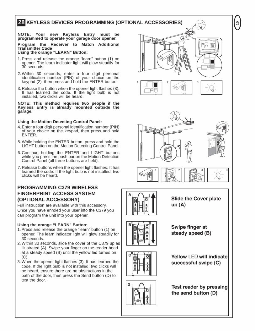
NOTE: Your new Keyless Entry must beprogrammed to operate your garage door opener.Program the Receiver to Match AdditionalTransmitter CodeUsing the orange “LEARN” Button:
1. Press and release the orange “learn” button (1) onopener. The learn indicator light will glow steadily for30 seconds.
2.Within 30 seconds, enter a four digit personalidentification number (PIN) of your choice on thekeypad (2), then press and hold the ENTER button.
3. Release the button when the opener light flashes (3).It has learned the code. If the light bulb is notinstalled, two clicks will be heard.
NOTE: This method requires two people if theKeyless Entry is already mounted outside thegarage.
Using the Motion Detecting Control Panel:4. Enter a four digit personal identification number (PIN)of your choice on the keypad, then press and holdENTER.
5.While holding the ENTER button, press and hold theLIGHT button on the Motion Detecting Control Panel.
6. Continue holding the ENTER and LIGHT buttonswhile you press the push bar on the Motion DetectionControl Panel (all three buttons are held).
7. Release buttons when the opener light flashes. It haslearned the code. If the light bulb is not installed, twoclicks will be heard.
PROGRAMMING C379 WIRELESSFINGERPRINT ACCESS SYSTEM(OPTIONAL ACCESSORY)Full instruction are available with this accessory.Once you have enroled your user into the C379 youcan program the unit into your opener.
Using the orange “LEARN” Button:1. Press and release the orange “learn” button (1) onopener. The learn indicator light will glow steadily for30 seconds.
2.Within 30 seconds, slide the cover of the C379 up asillustrated (A). Swipe your finger on the reader headat a steady speed (B) until the yellow led turnes on(C).
3.When the opener light flashes (3). It has learned thecode. If the light bulb is not installed, two clicks willbe heard, ensure there are no obstructions in thepath of the door, then press the Send button (D) totest the door.
28 KEYLESS DEVICES PROGRAMMING (OPTIONAL ACCESSORIES)

16
4
2
3
1
WHT-2
RED-1
5
6
6mm
1
2
4
WHTRED
1
4
33
2
3
LOCKLIGHT
Push Bar Cover
INSTALL DOOR CONTROL (OPTIONAL)
There are 2 terminals (1) on the back of the door control (2). Strip about 6mm (1/4") of insulation from bell wire(4). Separate wires enough to connect the white/red wire to RED terminal screw 1 and the white wire to WHTterminal screw 2.
Fasten the door control to an inside garage wall with sheet metal screws (3) provided. Drill 4mm (5/32") holes anduse anchors (6) if installing into plasterboard wall. A convenient place is beside the service door and out of reachof children.
Run the bell wire up the wall and across the ceiling to the garage door operator. Use insulated staples (5) tosecure wire. The receiver quick connect terminals are located behind the light lens of the operator. Connect thebell wire to the terminals as follows: white/red to red (1) and white to white (2).
Operation of the Door ControlPress to open or close the door. Press again to stop the door while moving.
29Locate door control where the garage door is visible, away from door and door hardware and outof the reach of children. Mount at least 1.5m (5 feet) above the floorSerious personal injury from a moving garage door may result from misuse of opener. Do notallow children to operate the door control or transmitter.
Permanently fasten the caution label permanently to the wall near the door control as a reminder of safeoperating procedures.

17
USING THE MOTION DETECTING CONTROL PANEL(optional accessory)
Press the push bar (1) to open or close the door. Press again to stop the door.
Light featurePress the light button to turn the opener light on or off. It will not control the openerlights when the door is in motion. If you turn it on and then activate the opener, thelight will remain on for 2 1/2 minutes. Press again to turn it off sooner. The 2 1/2minute interval can be changed to 1-1/2, 3-1/2 or 4-1/2 minutes as follows: Pressand hold the Lock button until the light flashes (about 10 seconds). A single flashindicates that the timer is reset to 1-1/2 minutes. Repeat the procedure and the lightwill flash twice, resetting the timer to 2-1/2 minutes. Repeat again for 3-1/2 minuteinterval, etc, up to a maximum of four flashes and 4-1/2 minutes.
Lock featureDesigned to prevent operation of the door from hand-held transmitters. However, thedoor will open and close from the Door Control, the Outside Keyswitch and theKeyless Entry Accessories.To activate, press and hold the Lock button for 2 seconds. The push bar light willflash as long as the Lock feature is on.To turn off, press and hold the Lock button again for 2 seconds. The push bar lightwill stop flashing.The Lock feature will also turn off whenever the “LEARN” button on the opener panelis activated.
30
LOCKLIGHT
A
B
8
7
6
5
SPECIAL FEATURESA. Door within a door connection
Open light lens. Locate auxiliary quick connect terminals. Insert bell wireinto quick connect terminals 8 and 7.
B. Flashing light connectionThe flashing light can be installed anywhere. Connect light leads to quickconnect terminals 6 and 5. Terminal 5 is ground.
31

18
ACCESSORIES
(1) Model CM844 4 Channel transmitter(2) Model CM128 Wireless Wall Button(3) Model C940 Single-Channel transmitter(4) Model C943 3-Channel transmitter(5) Model C945 3-Channel Mini transmitter(6) Model C98 Motion Detecting Control Panel(7) Model C840 Keyless Entry System
(8) Model C77 The Protector SystemTM IR Beams(9) Model CM1702 Quick Release Lock(10) Model 760E Outside Keyswitch(11) Model C379 Wireless Fingerprint Access System(12) Model ANT4X-1LM 433MHz Antenna, Cable and Adaptor(13) Model C198 LCD Motion Detecting Control Panel
32
536
1
10
11
2 LOCKLIGHT
4
C840
CM128 C98
760ECM1702C77
C940 C943 C945
7 89
CM844
12
ENROLL
FAIL
RETRY
SEND
PASS
READY
ENROLL
C379
13
C198

19
NOTICE
091B0019
RAIL GREASE
NO. 83A4 083A0011-1
178B0086B
012B0906178B0034B
7527SP1Segmented Pole Pack
012B0905
001A6829
ADR10068
171A0828
035A0070 002A0958
001A6698
001A6793-1
184A0242
012A0928142A0229
142A0230
REPLACEMENT PARTS33

20
If the supply cord is damaged, it must bereplaced by the manufacturer, its serviceagent or similarly qualified personsin order to avoid hazard.
041A5735C
041A0079
204C0161-2
041D0577
108C0082
041A5908
041A5797
158A0049
031D0587
REPLACEMENT PARTS34
CARE OF YOUR OPENER
When properly installed your opener will operate with minimal maintenance. The opener does not requireadditional lubrication.Limit and Force Adjustments: These adjustments must be checked and properly set when opener isinstalled. Only a screwdriver is required. Weather conditions may cause some minor changes in the dooroperation, requiring some re-adjustments, particularly during the first year of operation.Refer to the limit and force adjustments in sections 22 & 23. Follow the instructions carefully and repeat thesafety reverse test after any adjustment.Transmitter:The portable transmitter may be secured to a car sun visor with the clip provided. Additionalremotes can be purchased at any time for use in all vehicles using garage. Refer to Accessories. Any newremotes must be set to the same code as the original remote.Wireless Wall Button Batteries: When the light becomes dim or does not come on replace the batteries.Transmitter Battery: If transmission range decreases replace the battery.To Change Battery: To replace batteries, use the visor clip or screwdriver blade to pry open the case. Insertbatteries positive side up. To replace cover, snap shut along both sides. Do not dispose of the old battery withhousehold waste.
MAINTENANCE OF YOUR OPENER
Once a Month:• Repeat safety reverse test. Make any necessary adjustments.• Manually operate door. If it is unbalanced or binding, call for professional garage door service.• Check to be sure door opens and closes fully. Adjust Limits and/or Force if necessary.
Once a Year:Oil door rollers, bearings and hinges. Do not grease the door tracks.Clean and lubricate the pole and trolley. The opener does not require additional lubrication.

TROUBLE SHOOTING
21
1. Opener doesn't operate from either door control orremote:
• Does the opener have electric power? Plug lamp into outlet. Ifit doesn't light, check the fuse box or the circuit breaker.(Some outlets are controlled by a wall switch.)• Have you disengaged all door locks? Review installationinstruction warnings on page 1.• Is there a build-up of ice or snow under door? The door maybe frozen to ground. Remove any obstruction.• The garage door spring may be broken. Have it replaced.2. Opener operates from remote but not from door control:• Is door control button lit? If not, remove the bell wire from theopener terminals. Short the red and white terminals bytouching both terminals at the same time with a piece of wire.If the opener runs, check for a faulty wire connection at thedoor control, a short under the staples, or a broken wire.• Are wiring connections correct? Review step 29.3. Door operates from door control but not from remote:• Replace battery if necessary.• If you have two or more remotes and only one operates,review Program Your Opener, Remote and Keyless Entrysteps 27 and 28.• Is the door control button flashing? The opener is in lockmode. If you have a Motion Detecting Control Panel, pushand hold the Lock button for 2 seconds. The door controlbutton will stop flashing.
4. Remote has short range:• Is battery installed?• Change the location of the transmitter on the car.• A metal garage door, foil-backed insulation or metal siding willreduce the transmission range.
5. Door reverses for no apparent reason and opener lightdoesn't flash:
• Is something obstructing the door? Pull manual releasehandle. Operate door manually. If it is unbalanced or binding,call for professional garage door service.• Clear any ice or snow from garage floor area where garagedoor closes.• Repeat Setting Limits and Force, see adjustment steps 22and 23.Repeat safety reverse test after adjustment is complete.6. Door reverses for no apparent reason and opener light
flashes for 5 seconds after reversing:Check The Protector System™ (if you have installed thisaccessory). If the light is flashing, correct alignment.7. Opener noise is disturbing in living quarters of home:If operational noise is a problem because of proximity of theopener to the living quarters, Vibration Isolator Kit 89LM can beinstalled. This kit was designed to reduce the "sounding boardeffect" and is easy to install.8. The garage door opens and closes by itself:Make sure remote push button is not stuck "on". For peace ofmind, install an Open Door Monitor so you can check the statusof your door.9. Door stops but doesn't close completely:Repeat Setting the Limits, see adjustment step 22.Repeat safety reverse test after any adjustment of door armlength, close force or down limit.10. Door opens but won't close:• Check The Protector System™ (if you have installed thisaccessory). If the light is flashing, correct alignment.• If opener light does not flash and it is a new installation,repeat Setting the Limit and Force steps 22 and 23.Repeat the safety reverse test after the adjustment is complete.11. Opener light does not turn on:Replace light bulb ( BA15s 24V/21W maximum).12. Opener strains:Door may be unbalanced or springs are broken. Close doorand use manual release rope and handle to disconnect trolley.Open and close door manually. A properly balanced door willstay in any point of travel while being supported entirely by itssprings. If it does not, call for professional garage door serviceto correct the problem.
13. Opener motor hums briefly, then won't work:• Garage door springs are broken. SEE ABOVE.• If problem occurs on first operation of opener, door is locked.Disable door lock. Repeat safety reverse test after adjustmentis complete.
14. Opener won't activate due to power failure:• Pull manual release rope and handle down to disconnecttrolley. Door can be opened and closed manually. When thepower is restored, pull the manual release handle down andtoward opener. The next time the opener is activated, thetrolley will reconnect.• The Outside Quick Release accessory (if fitted) disconnectsthe trolley from outside the garage in case of power failure.
15. Setting the limits manually:• Press and hold the black button until the yellow indicator lightstarts flashing slowly then release.• Adjust the position of the door by using the black and orangebuttons. Black moves the door UP (open) and orange movesthe door DOWN (close).Check to be sure the door opens high enough for yourvehicle.• Push the transmitter or door control. This sets the UP (open)limit and begins closing the door.Immediately press either the orange or the black button.The door will stop.Adjust the desired DOWN (close) limit position using the blackand orange buttons. Check to be sure the door is fullyclosed without applying excessive pressure on the pole (poleshould not bow upwards and the chaint should not sag or droopbelow the pole). Push the transmitter or door control. This setsthe DOWN (close) limit and begins opening the door.NOTE: If neither the black or the orange button is pressed,the door will reverse off the floor and the DOWN travel limitwill be set automatically.• Open and close the door with the transmitter or door control 2or 3 times.• If the door does not stop in the desired UP (open) position orreverses before the door stops at the DOWN (close) position,repeat Setting the Limits and Force, see adjustment steps 22and 23.• If the door stops in both the desired UP (open) and DOWN(close) positions, proceed to Test the Safety Reversal System.

22
Your opener can be activated by any of the following devices:• The Motion Detecting Control Panel. Hold the buttondown until door starts to move.• The Outside Keyswitch or Keyless Entry System (if youhave installed either of these accessories).• The Transmitter. Hold the push button down until the doorstarts to move.Opening the Door Manually: Door should be fully closedif possible. Weak or broken springs could allow an opendoor to fall rapidly. Property damage or serious personalinjury could result.The door can be opened manually by pulling the releasehandle down. To reconnect the door, pull the release handledown and toward the opener.Do not use the manual release handle to pull the dooropener or closed. When the Opener is Activated byTransmitter or Lighted Door Control Button:1. If open, the door will close. If closed, the door will open.2. If closing, the door will stop.3. If opening, the door will stop (allowing space for entry andexit of pets and for fresh air).
4. If the door has been stopped in a partially open or closedposition, it will reverse direction.
5. If an obstruction is encountered while closing, the door willreverse.
6. If an obstruction is encountered while opening, the door willreverse and stop.
7. The optional Protector System™ uses an invisible beamwhich, when broken by an obstruction, causes a closingdoor to open and prevents an open door from closing. It isSTRONGLY RECOMMENDED for homeowners with youngchildren.
Allow a 15 minute cooling period after 5 continuousoperations of the opener. The opener light will turn on: 1.when opener is initially plugged in; 2. when the power isbriefly interrupted; 3. when the opener is activated.The light turns off automatically after 2-1/2 minutes. Bulb sizeis 24V/21W maximum.
OPERATION OF YOUR OPENER SPECIFICATIONSInput Voltage...................230-240 VAC, 50HzMax. Pull Force ..............600NPower .............................100WStandby Power ...............3 watt (nominal)Normal Torque ................5NmMax door weight.............70kgs
MotorType................................DC gearmotor permanent lubrication
Drive MechanismDrive ...............................Chain with two-piece trolley on steel pole.Length of Travel..............Adjustable to 2750mm (3.0m Pole)
2500mm (2.75m Pole)Travel Rate .....................127-178mm per secondLamp...............................On when door starts, off 2-1/2 minutes
after stop (BA15s, 24V/21W)Door Linkage ..................Adjustable door arm. Pull cord trolley release.
SafetyPersonal .........................Push button stop in UP and DOWN
direction. Automatic safety reverse in DOWNdirection and stop in UP.
Electronic ........................Automatic force adjustmentElectrical .........................Transformer overload protector and low
voltage push button wiring.Limit Device ....................Optical RPM/Passpoint detector.Limit Adjustment .............Electronic, Semi and Fully Automatic.Start Circuit.....................Low voltage push button circuit.
DimensionsLength (Overall)..............3340mm (3.0m pole)
3090mm (2.75m pole)Headroom Required .......60mmHanging Weight ..............10.5kg
ReceiverMemory Registers ..........12Operating Frequency......433.92MHz
SPECIAL NOTE: Chamberlain strongly recommends that the Protector System TM be installed on all garage door openers.

114A3759C © 2009 The Chamberlain Group, Inc
Liability – Australia onlyUnder no circumstances shall the Seller be liable forconsequential, incidental or special damages arising inconnection with the use, or inability to use, the Unit. In noevent shall the Seller's liability for damages or injury arisingfrom breach of law or contract or for negligence, exceed thecost of repairing or replacing the Unit or refunding thepurchase price of the Unit.
Under Division 2 Part V of the Trade Practices Act, 1974,certain warranties and conditions (Implied Terms) are impliedinto contracts for the supply of goods or services if the goodsor services are of a kind ordinarily acquired for personal,domestic or household use or consumption. Liability forbreach of those Implied Terms cannot be excluded or limitedand the limitations and exclusions above do not apply to theImplied Terms.
Except for the Implied Terms and the warranties set outabove, the Seller excludes all warranties and conditionsimplied by statute, at law, in fact or otherwise.
Liability – New Zealand onlyExcept as set out in the Fair Trading Act 1986 and theConsumer Guarantees Act 1993:
(a) all other guarantees, warranties and representations inrelation to the Unit or its supply are excluded to the extentthat the Seller can lawfully exclude them; and(b) under no circumstances shall the Seller be liable forconsequential, incidental or special damages arising inconnection with the use, or inability to use, the Unit, otherthan those which were reasonably foreseeable as liableto result from the failure.
NOTE: We request that you attach your sales docket orinvoice to this manual to enable you to establish the dateof purchase in the unlikely event of a service call beingmade. Chamberlain reserves the right to change thedesign and specification without prior notification. Somefeatures or accessories may not be available in certainmarkets or areas. Please check with your distributor.
CONTACT DETAILS:
Chamberlain service centres:AustraliaPhone toll free 1800 638 234Fax toll free 1800 888 121
New ZealandAuckland phone 09 477 2823Phone toll free 0800 653 667Fax toll free 0800 653 663
www.chamberlainanz.com
CHAMBERLAIN 2 YEAR LIMITED WARRANTYMerlin MT60PGarage Door Operator
Chamberlain Australia Pty Limited / Chamberlain NewZealand Limited (Seller) warrants to the originalpurchaser of the Merlin MT60P Garage Door Opener(Unit) that it is free from defects in material and/orworkmanship for a period of 2 YEARS from the date offirst purchase from the Seller.
Please retain your proof-of-purchase in the unlikely event yourequire warranty service.If, during the limited warranty period, the Unit fails due todefects in materials or workmanship Chamberlain will,provided the defective part or Unit is returned freight andinsurance prepaid and well packaged to the nearestChamberlain office or authorised installer, undertake to repairor, at its option, replace any defective part or Unit and returnit to the Buyer at no cost. Repairs and replacement parts arewarranted for the remaining portion of the original warrantyperiod.
Limited warranty on openerChamberlain will furnish a replacement opener free of charge,if it is found to be defective. Labour costs may apply.Where the Unit has been installed by an authorised installer,Chamberlain will furnish replacement parts free of chargethrough the authorised installer. A service fee for on-siteservice may apply.
In-warranty serviceDuring the warranty period, if the product appears as thoughit may be defective, call our toll free service before removal ofthe unit. A Chamberlain technician will diagnose the problemand promptly supply you with the parts for “do-it-yourself”repairs, or provide you with shipping instructions for a factoryrepair or replacement. If an authorised installer installed yourunit you must call them for prompt on-site service.
If our service centre determines that a warranty claim hasbeen made in respect of a failure or defect arising out of anyexclusion set out below, we may charge you a fee to repairand/or return the Unit to you.
ExclusionsThis warranty does not cover any failure of the Unit due to:1. non-compliance with the instructions regarding installation,operation, maintenance and testing of the Unit or of anyproduct with which the Unit is used.2. any attempt to repair, dismantle, reinstall or move theProduct to another location once the Product is installed byany person other than an authorised installer.3. tampering, neglect, abuse, wear and tear, accident,electrical storm, excessive use or conditions other thannormal domestic use.This warranty does not cover any problems with, or relatingto, the garage door or garage door hardware, including butnot limited to the door springs, door rollers, door alignment orhinges, any problems caused by electrical faults, replacementof batteries or light bulbs or labour charges for reinstalling arepaired or replaced Units.
23