mt050b series dryline dehydrator user … · mt050b series dryline® dehydrator user manual 4...
TRANSCRIPT
MT050B SERIES DryLine® DEHYDRATOR
USER MANUAL
Bulletin AE01B-A0554-001 Rev: N © 2009 - 2012 CommScope, Inc. All rights reserved. (12/12)
MT050B SERIES DryLine® DEHYDRATOR USER MANUAL
2
Table of Contents
Section 1 General Information . . . . . . . . . . . . . . . . . . . . . . . . . . . . . . . . . . . . . . . 41.1 Introduction. . . . . . . . . . . . . . . . . . . . . . . . . . . . . . . . . . . . . . . . . . . 41.2 Description . . . . . . . . . . . . . . . . . . . . . . . . . . . . . . . . . . . . . . . . . . . 41.3 Operation . . . . . . . . . . . . . . . . . . . . . . . . . . . . . . . . . . . . . . . . . . . . 41.4 Alarms . . . . . . . . . . . . . . . . . . . . . . . . . . . . . . . . . . . . . . . . . . . . . 5 Figure 1 - Terminal Strip Summary . . . . . . . . . . . . . . . . . . . . . . . . . . . . . . . . . . . .5 Figure 2 - Terminal Strip Discrete . . . . . . . . . . . . . . . . . . . . . . . . . . . . . . . . . . . . .5 Figure 3 - Control Board . . . . . . . . . . . . . . . . . . . . . . . . . . . . . . . . . . . . . . . . . . .61.5 SpecificationsMT050BDehydrator . . . . . . . . . . . . . . . . . . . . . . . . . . . . . 6
Section 2 Installation . . . . . . . . . . . . . . . . . . . . . . . . . . . . . . . . . . . . . . . . . . . . . . 72.1 Unpacking and Inspection. . . . . . . . . . . . . . . . . . . . . . . . . . . . . . . . . . . 72.2 Controls and Displays . . . . . . . . . . . . . . . . . . . . . . . . . . . . . . . . . . . . . 72.2.1 Event Log Codes . . . . . . . . . . . . . . . . . . . . . . . . . . . . . . . . . . . . . . . 72.3 InstallingtheDehydrator . . . . . . . . . . . . . . . . . . . . . . . . . . . . . . . . . . . 72.3.1 19”RackMounting/wallmountingorsetonoptionalshelf . . . . . . . . . . . . . . . . . 72.4 PowerConnections . . . . . . . . . . . . . . . . . . . . . . . . . . . . . . . . . . . . . . 72.4.1 ACPower . . . . . . . . . . . . . . . . . . . . . . . . . . . . . . . . . . . . . . . . . . . . 82.4.2 DCPower. . . . . . . . . . . . . . . . . . . . . . . . . . . . . . . . . . . . . . . . . . . . 82.4.3 TesttheDehydrator . . . . . . . . . . . . . . . . . . . . . . . . . . . . . . . . . . . . . . 82.4.4 Connect to Dry Air Cable System . . . . . . . . . . . . . . . . . . . . . . . . . . . . . . 82.5 ConnectingtheAlarmOutputs . . . . . . . . . . . . . . . . . . . . . . . . . . . . . . . . 82.6 ConnectingDehydratortotheTransmissionLine . . . . . . . . . . . . . . . . . . . . . . 82.7 PurgingtheTransmissionLine . . . . . . . . . . . . . . . . . . . . . . . . . . . . . . . . 92.8 Adjusting Output Pressure . . . . . . . . . . . . . . . . . . . . . . . . . . . . . . . . . . 9
Section 3 Maintenance . . . . . . . . . . . . . . . . . . . . . . . . . . . . . . . . . . . . . . . . . . . 103.0 Maintenance . . . . . . . . . . . . . . . . . . . . . . . . . . . . . . . . . . . . . . . . . 103.1 RegularMaintenance . . . . . . . . . . . . . . . . . . . . . . . . . . . . . . . . . . . . 103.2 PreventiveMaintenance . . . . . . . . . . . . . . . . . . . . . . . . . . . . . . . . . . 103.3 DehydratorFilterElementReplacement. . . . . . . . . . . . . . . . . . . . . . . . . . 103.4 Annual Inspection . . . . . . . . . . . . . . . . . . . . . . . . . . . . . . . . . . . . . . 103.4.1 Checktheelectricalconnections. . . . . . . . . . . . . . . . . . . . . . . . . . . . . . 113.4.2 Checkthegroundwire. . . . . . . . . . . . . . . . . . . . . . . . . . . . . . . . . . . . 113.4.3 Checkthehourmeter . . . . . . . . . . . . . . . . . . . . . . . . . . . . . . . . . . . . 113.5 PartsReplacementandDehydratorOverhaul . . . . . . . . . . . . . . . . . . . . . . 113.5.1 InCaseOfDifficulty: . . . . . . . . . . . . . . . . . . . . . . . . . . . . . . . . . . . . 113.5.2 Tools . . . . . . . . . . . . . . . . . . . . . . . . . . . . . . . . . . . . . . . . . . . . . 113.5.3 OverhaulProcedure . . . . . . . . . . . . . . . . . . . . . . . . . . . . . . . . . . . . . 113.5.4 UnitShutdownandRemoval . . . . . . . . . . . . . . . . . . . . . . . . . . . . . . . . 113.5.5 Removethecompressorforoverhaul. . . . . . . . . . . . . . . . . . . . . . . . . . . 12
MT050B SERIES DryLine® DEHYDRATOR USER MANUAL
3
3.6 Service Restoration . . . . . . . . . . . . . . . . . . . . . . . . . . . . . . . . . . . . . 12Section 4 Troubleshooting. . . . . . . . . . . . . . . . . . . . . . . . . . . . . . . . . . . . . . . . . 13
Figure4-WireSchematicwithSummaryAlarm . . . . . . . . . . . . . . . . . . . . . . . . . . 14 Figure5-WireSchematicwithDiscreteAlarm . . . . . . . . . . . . . . . . . . . . . . . . . . . 15 Figure 6 - Pneumatic Diagram . . . . . . . . . . . . . . . . . . . . . . . . . . . . . . . . . . . . . . 16
Section 5 Replacement Parts . . . . . . . . . . . . . . . . . . . . . . . . . . . . . . . . . . . . . . . 17 OverhaulKit . . . . . . . . . . . . . . . . . . . . . . . . . . . . . . . . . . . . . . . . . . . . . . . . . . 17 MT050B-KIT-OVRHL . . . . . . . . . . . . . . . . . . . . . . . . . . . . . . . . . . . . . . . . . . . . 17 FilterElementReplacementKit . . . . . . . . . . . . . . . . . . . . . . . . . . . . . . . . . . . . . 17 MT050B-KIT-ELMNT . . . . . . . . . . . . . . . . . . . . . . . . . . . . . . . . . . . . . . . . . . . . 17 FilterBowlAssembleReplacementKit . . . . . . . . . . . . . . . . . . . . . . . . . . . . . . . . . 17 MT050B-KIT-FLTRS . . . . . . . . . . . . . . . . . . . . . . . . . . . . . . . . . . . . . . . . . . . . . 17 FilterBowlAssembleandDryerTubeReplacementKit . . . . . . . . . . . . . . . . . . . . . 17 MT050B-KIT-DRYER . . . . . . . . . . . . . . . . . . . . . . . . . . . . . . . . . . . . . . . . . . . . 17 Solenoid Replacement . . . . . . . . . . . . . . . . . . . . . . . . . . . . . . . . . . . . . . . . . . . 17 KitMT050B-KIT-SOLND . . . . . . . . . . . . . . . . . . . . . . . . . . . . . . . . . . . . . . . . . . 17
Section 6 Customer Service . . . . . . . . . . . . . . . . . . . . . . . . . . . . . . . . . . . . . . . . 176.0 Introduction. . . . . . . . . . . . . . . . . . . . . . . . . . . . . . . . . . . . . . . . . . 176.1 InCaseofTrouble . . . . . . . . . . . . . . . . . . . . . . . . . . . . . . . . . . . . . . 176.2 InitialStepsbyCOMMSCOPE . . . . . . . . . . . . . . . . . . . . . . . . . . . . . . . 186.3 Repair Center Process . . . . . . . . . . . . . . . . . . . . . . . . . . . . . . . . . . . 186.4 RoHSInquiries . . . . . . . . . . . . . . . . . . . . . . . . . . . . . . . . . . . . . . . . 18
Section 7 DC Inverter Option . . . . . . . . . . . . . . . . . . . . . . . . . . . . . . . . . . . . . . . 197.1 Introduction. . . . . . . . . . . . . . . . . . . . . . . . . . . . . . . . . . . . . . . . . . 197.2 Installingthe24VdctoACinverter . . . . . . . . . . . . . . . . . . . . . . . . . . . . 197.3 Installingthe48VdctoACinverter . . . . . . . . . . . . . . . . . . . . . . . . . . . . 20
Table of Contents continued
MT050B SERIES DryLine® DEHYDRATOR USER MANUAL
4
Section 1 General Information1.1 Introduction
Thismanualcontainstheinformationyouneedtoinstall,operateandmaintainyourMT050BSeries DryLine®dehydrator.Pleasetakethetimetoreadthismanualbeforeattemptingtooperateorservicetheunit.
This appliance is not intended for access by the general public.
This appliance is not intended for use by persons (including children) with reduced physical, sensory or mental capabilities, or lack of experience and knowledge, unless they have been given supervision or instruction concerning use of the appliance by a person responsible for their safety.
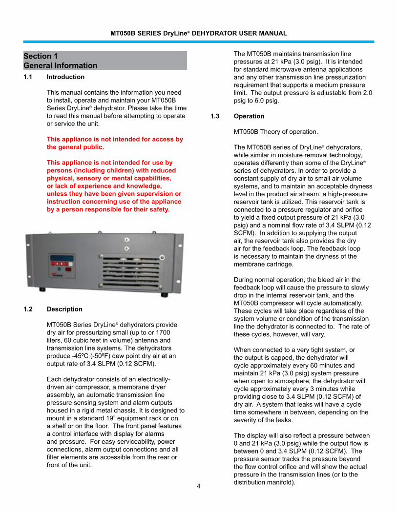
1.2 Description
MT050BSeriesDryLine®dehydratorsprovidedryairforpressurizingsmall(uptoor1700liters,60cubicfeetinvolume)antennaandtransmissionlinesystems.Thedehydratorsproduce-45ºC(-50ºF)dewpointdryairatanoutputrateof3.4SLPM(0.12SCFM).
Eachdehydratorconsistsofanelectrically-driven air compressor, a membrane dryer assembly, an automatic transmission line pressure sensing system and alarm outputs housedinarigidmetalchassis.Itisdesignedtomountinastandard19”equipmentrackoronashelforonthefloor.Thefrontpanelfeaturesacontrolinterfacewithdisplayforalarmsandpressure.Foreasyserviceability,powerconnections, alarm output connections and all filterelementsareaccessiblefromtherearorfrontoftheunit.
TheMT050Bmaintainstransmissionlinepressuresat21kPa(3.0psig).Itisintendedforstandardmicrowaveantennaapplicationsandanyothertransmissionlinepressurizationrequirementthatsupportsamediumpressurelimit.Theoutputpressureisadjustablefrom2.0psig to 6.0 psig.
1.3 Operation
MT050BTheoryofoperation. TheMT050BseriesofDryLine®dehydrators,whilesimilarinmoistureremovaltechnology,operatesdifferentlythansomeoftheDryLine®
seriesofdehydrators.Inordertoprovideaconstantsupplyofdryairtosmallairvolumesystems, and to maintain an acceptable dryness levelintheproductairstream,ahigh-pressurereservoirtankisutilized.Thisreservoirtankisconnectedtoapressureregulatorandorificetoyieldafixedoutputpressureof21kPa(3.0psig)andanominalflowrateof3.4SLPM(0.12SCFM).Inadditiontosupplyingtheoutputair,thereservoirtankalsoprovidesthedryairforthefeedbackloop.Thefeedbackloopisnecessarytomaintainthedrynessofthemembrane cartridge.
Duringnormaloperation,thebleedairinthefeedbackloopwillcausethepressuretoslowlydropintheinternalreservoirtank,andtheMT050Bcompressorwillcycleautomatically.Thesecycleswilltakeplaceregardlessofthesystemvolumeorconditionofthetransmissionlinethedehydratorisconnectedto.Therateofthesecycles,however,willvary.
Whenconnectedtoaverytightsystem,ortheoutputiscapped,thedehydratorwillcycleapproximatelyevery60minutesandmaintain21kPa(3.0psig)systempressurewhenopentoatmosphere,thedehydratorwillcycleapproximatelyevery3minuteswhileprovidingcloseto3.4SLPM(0.12SCFM)ofdryair.Asystemthatleakswillhaveacycletimesomewhereinbetween,dependingontheseverityoftheleaks.
Thedisplaywillalsoreflectapressurebetween0and21kPa(3.0psig)whiletheoutputflowisbetween0and3.4SLPM(0.12SCFM).Thepressuresensortracksthepressurebeyondtheflowcontrolorificeandwillshowtheactualpressureinthetransmissionlines(ortothedistributionmanifold).
MT050B SERIES DryLine® DEHYDRATOR USER MANUAL
5
Duringtheinitialpressurizationofthetransmissionline,thedehydratorwillcycleevery2to4minuteswiththesystemat0psigpressure.Asthedehydratorpressurizesthesystem,thecycletimeswillincreaseandthepressurewillriseuntilthedehydratoroutputisbalancedwiththesystemleak,atwhichpointthecycletimeswillstabilize.
1.4 Alarms
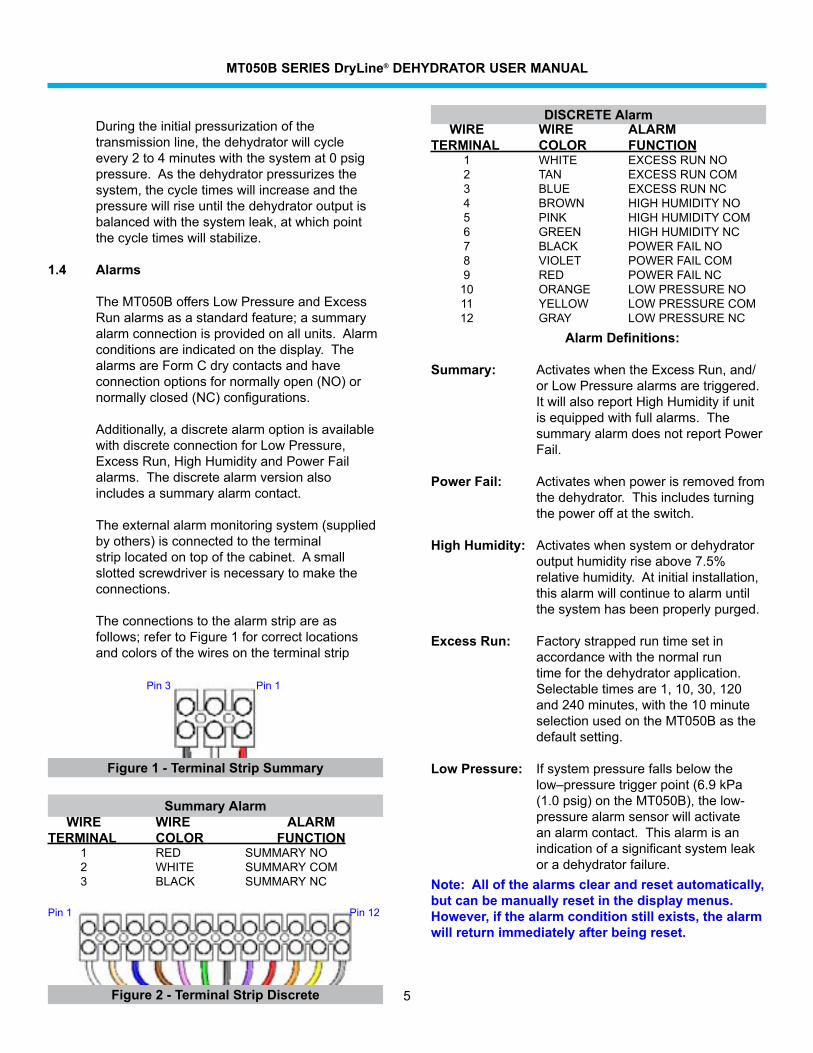
TheMT050BoffersLowPressureandExcessRunalarmsasastandardfeature;asummaryalarm connection is provided on all units. Alarm conditionsareindicatedonthedisplay.ThealarmsareFormCdrycontactsandhaveconnectionoptionsfornormallyopen(NO)ornormallyclosed(NC)configurations.
Additionally, a discrete alarm option is available withdiscreteconnectionforLowPressure,ExcessRun,HighHumidityandPowerFailalarms.Thediscretealarmversionalsoincludes a summary alarm contact.
Theexternalalarmmonitoringsystem(suppliedbyothers)isconnectedtotheterminalstriplocatedontopofthecabinet.Asmallslottedscrewdriverisnecessarytomaketheconnections.
Theconnectionstothealarmstripareasfollows;refertoFigure1forcorrectlocationsandcolorsofthewiresontheterminalstrip
Note: All of the alarms clear and reset automatically, but can be manually reset in the display menus. However, if the alarm condition still exists, the alarm will return immediately after being reset.
WIRE WIRE ALARMTERMINAL COLOR FUNCTION 1 RED SUMMARYNO 2 WHITE SUMMARYCOM 3 BLACK SUMMARYNC
Summary Alarm
WIRE WIRE ALARMTERMINAL COLOR FUNCTION 1 WHITE EXCESSRUNNO 2 TAN EXCESSRUNCOM 3 BLUE EXCESSRUNNC 4 BROWN HIGHHUMIDITYNO 5 PINK HIGHHUMIDITYCOM 6 GREEN HIGHHUMIDITYNC 7 BLACK POWERFAILNO 8 VIOLET POWERFAILCOM 9 RED POWER FAIL NC 10 ORANGE LOWPRESSURENO 11 YELLOW LOWPRESSURECOM 12 GRAY LOWPRESSURENC
DISCRETE Alarm
Alarm Definitions:
Summary: ActivateswhentheExcessRun,and/orLowPressurealarmsaretriggered.ItwillalsoreportHighHumidityifunitisequippedwithfullalarms.ThesummaryalarmdoesnotreportPowerFail.
Power Fail: Activateswhenpowerisremovedfromthedehydrator.Thisincludesturningthepoweroffattheswitch.
High Humidity: Activateswhensystemordehydratoroutputhumidityriseabove7.5%relativehumidity.Atinitialinstallation,thisalarmwillcontinuetoalarmuntilthesystemhasbeenproperlypurged.
Excess Run: Factory strapped run time set in accordancewiththenormalruntimeforthedehydratorapplication.Selectable times are 1, 10, 30, 120 and240minutes,withthe10minuteselectionusedontheMT050Basthedefaultsetting.
Low Pressure: Ifsystempressurefallsbelowthelow–pressuretriggerpoint(6.9kPa(1.0psig)ontheMT050B),thelow-pressurealarmsensorwillactivateanalarmcontact.Thisalarmisanindicationofasignificantsystemleakoradehydratorfailure.
Figure 1 - Terminal Strip Summary
Pin 3 Pin 1
Pin 1 Pin 12
Figure 2 - Terminal Strip Discrete
MT050B SERIES DryLine® DEHYDRATOR USER MANUAL
6
Output Pressure Constant,kPa(psig) 21(3.0)
Outputcapacity 3.4SLPH(1.2SCFH) 5.6SLPM(0.2SCFM) (total,approx.)
OutputDewPoint, –45°C(-50°F) or better
OperatingTemperatureRange -10°to+50°C (+14°to+122°F)
ElectricalInput 115±10%Vac,60Hz 240±10%Vac,50Hz 24or48VdcwithInverter
OutputConnector 3/8”polytube,compression
Dimensions Height,cm(in) 48.26(19) Width,cm(in) 17.8(7) Depth,cm(in) 41.91(16.5) Netweight,kg(lb.) 16.1(351/2)
Alarms
PowerFailAlarm lossofinputpower
HighHumidityAlarmSetPoint 7.5%RH, factoryset
ExcessRunAlarm 10minutes,factoryset
LowPressureAlarm,kPa(psig) 6.9(1.0)
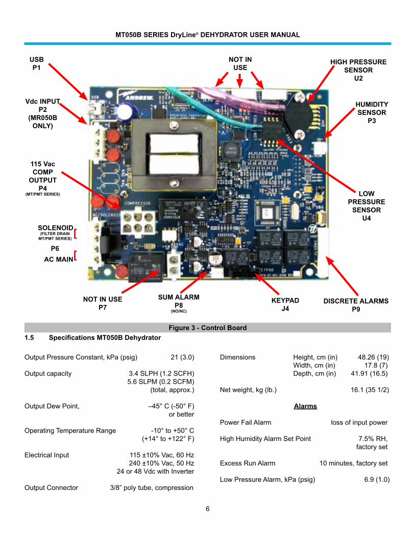
1.5 Specifications MT050B DehydratorFigure 3 - Control Board
HUMIDITY SENSOR
P3
NOT IN USE
NOT IN USEP7
SUM ALARMP8
(NO/NC)
KEYPADJ4
DISCRETE ALARMSP9
115 Vac COMP
OUTPUTP4
(MT/PMT SERIES)
Vdc INPUTP2
(MR050B ONLY)
LOW PRESSURE
SENSORU4
HIGH PRESSURE SENSOR
U2
USBP1
SOLENOID(FILTER DRAIN
MT/PMT SERIES)
P6AC MAIN
[
[
MT050B SERIES DryLine® DEHYDRATOR USER MANUAL
7
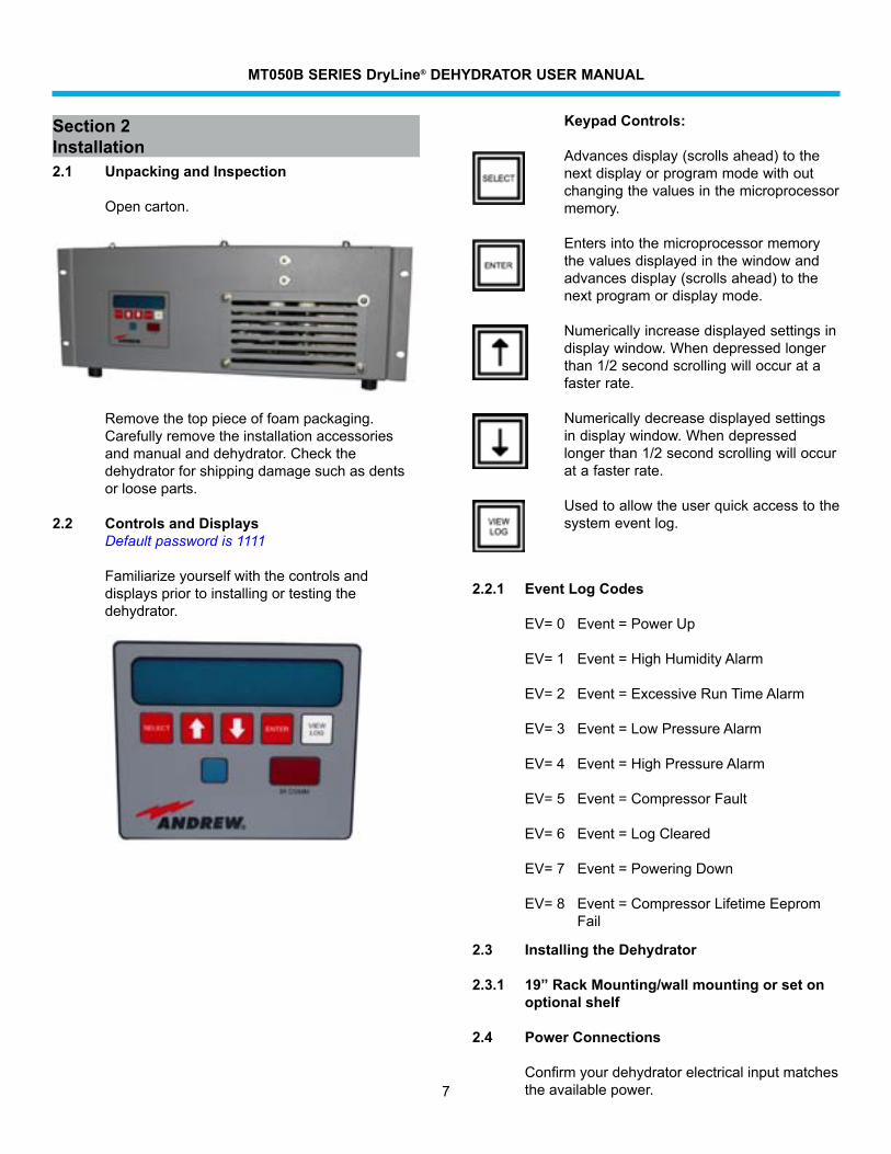
Section 2Installation2.1 Unpacking and Inspection
Open carton.
Removethetoppieceoffoampackaging.Carefullyremovetheinstallationaccessoriesandmanualanddehydrator.Checkthedehydratorforshippingdamagesuchasdentsor loose parts.
2.2 Controls and DisplaysDefault password is 1111
Familiarizeyourselfwiththecontrolsanddisplayspriortoinstallingortestingthedehydrator.
Keypad Controls:
Advancesdisplay(scrollsahead)tothenextdisplayorprogrammodewithoutchangingthevaluesinthemicroprocessormemory.
Entersintothemicroprocessormemorythevaluesdisplayedinthewindowandadvancesdisplay(scrollsahead)tothenextprogramordisplaymode.
Numerically increase displayed settings in displaywindow.Whendepressedlongerthan1/2secondscrollingwilloccuratafasterrate.
Numerically decrease displayed settings indisplaywindow.Whendepressedlongerthan1/2secondscrollingwilloccuratafasterrate.
Usedtoallowtheuserquickaccesstothesystem event log.
2.3 Installing the Dehydrator
2.3.1 19” Rack Mounting/wall mounting or set on optional shelf
2.4 Power Connections
Confirmyourdehydratorelectricalinputmatchestheavailablepower.
2.2.1 Event Log Codes
EV=0 Event=PowerUp
EV=1 Event=HighHumidityAlarm
EV=2 Event=ExcessiveRunTimeAlarm
EV=3 Event=LowPressureAlarm
EV=4 Event=HighPressureAlarm
EV=5 Event=CompressorFault
EV=6 Event=LogCleared
EV=7 Event=PoweringDown
EV=8 Event=CompressorLifetimeEepromFail
MT050B SERIES DryLine® DEHYDRATOR USER MANUAL
8
2.4.3 Test the Dehydrator
TurnthedehydratorONandchecktheoutputforairflow.
2.4.4 Connect to Dry Air Cable System
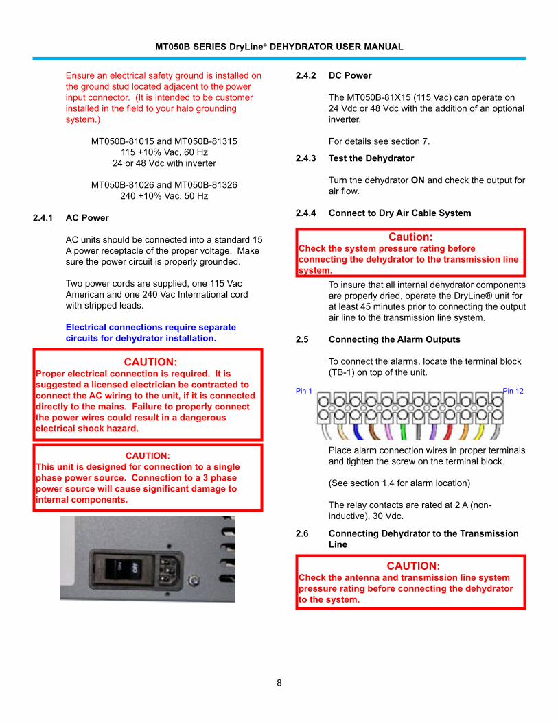
Placealarmconnectionwiresinproperterminalsandtightenthescrewontheterminalblock.
(Seesection1.4foralarmlocation)
Therelaycontactsareratedat2A(non-inductive),30Vdc.
2.6 Connecting Dehydrator to the Transmission Line
CAUTION:Check the antenna and transmission line system pressure rating before connecting the dehydrator to the system.
2.4.2 DC Power
TheMT050B-81X15(115Vac)canoperateon24Vdcor48Vdcwiththeadditionofanoptionalinverter.
For details see section 7.
CAUTION:Proper electrical connection is required. It is suggested a licensed electrician be contracted to connect the AC wiring to the unit, if it is connected directly to the mains. Failure to properly connect the power wires could result in a dangerous electrical shock hazard.
Toinsurethatallinternaldehydratorcomponentsareproperlydried,operatetheDryLine®unitforatleast45minutespriortoconnectingtheoutputairlinetothetransmissionlinesystem.
2.5 Connecting the Alarm Outputs
Toconnectthealarms,locatetheterminalblock(TB-1)ontopoftheunit.
Caution: Check the system pressure rating before connecting the dehydrator to the transmission line system.
CAUTION:This unit is designed for connection to a single phase power source. Connection to a 3 phase power source will cause significant damage to internal components.
Pin 1 Pin 12
Ensureanelectricalsafetygroundisinstalledonthegroundstudlocatedadjacenttothepowerinputconnector.(Itisintendedtobecustomerinstalledinthefieldtoyourhalogroundingsystem.)
MT050B-81015andMT050B-81315115 +10%Vac,60Hz
24or48Vdcwithinverter
MT050B-81026andMT050B-81326240 +10%Vac,50Hz
2.4.1 AC Power
ACunitsshouldbeconnectedintoastandard15Apowerreceptacleofthepropervoltage.Makesurethepowercircuitisproperlygrounded.
Twopowercordsaresupplied,one115VacAmericanandone240VacInternationalcordwithstrippedleads.
Electrical connections require separate circuits for dehydrator installation.
MT050B SERIES DryLine® DEHYDRATOR USER MANUAL
9
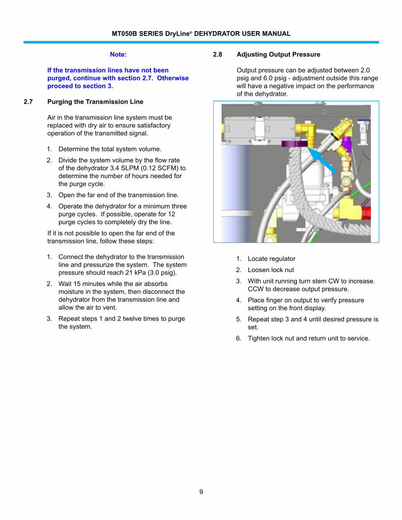
1. Locate regulator
2. Loosen lock nut
3. WithunitrunningturnstemCWtoincrease.CCW to decrease output pressure.
4. Placefingeronoutputtoverifypressuresettingonthefrontdisplay.
5. Repeat step 3 and 4 until desired pressure is set.
6. Tightenlocknutandreturnunittoservice.
2.8 Adjusting Output Pressure
Outputpressurecanbeadjustedbetween2.0psigand6.0psig-adjustmentoutsidethisrangewillhaveanegativeimpactontheperformanceofthedehydrator.
Note:
If the transmission lines have not been purged, continue with section 2.7. Otherwise proceed to section 3.
2.7 Purging the Transmission Line
Airinthetransmissionlinesystemmustbereplacedwithdryairtoensuresatisfactoryoperationofthetransmittedsignal.
1. Determinethetotalsystemvolume.
2. Dividethesystemvolumebytheflowrateofthedehydrator3.4SLPM(0.12SCFM)todeterminethenumberofhoursneededforthepurgecycle.
3. Openthefarendofthetransmissionline.
4. Operatethedehydratorforaminimumthreepurgecycles.Ifpossible,operatefor12purgecyclestocompletelydrytheline.
Ifitisnotpossibletoopenthefarendofthetransmissionline,followthesesteps:
1. Connectthedehydratortothetransmissionlineandpressurizethesystem.Thesystempressureshouldreach21kPa(3.0psig).
2. Wait15minuteswhiletheairabsorbsmoistureinthesystem,thendisconnectthedehydratorfromthetransmissionlineandallowtheairtovent.
3. Repeatsteps1and2twelvetimestopurgethesystem.
MT050B SERIES DryLine® DEHYDRATOR USER MANUAL
10
3.0 Maintenance
TheMT050BDehydratorrequiresrelativelylittlemaintenancetoensuresatisfactoryoperationoverlongperiodsoftime.Thissectionoutlinestherecommendedannualpreventivemaintenancefortheunitandthesuggestedoverhaulforevery6000hoursofcompressoroperation.
3.1 Regular Maintenance
TheMT050BDehydratorwillperformatanoptimumifitisroutinelycheckedforcorrectperformance.Thischeckinggenerallyconsistsofanannualinspectionoftheconditionoftheairintakefilterandanoverhaulafterevery6000hoursofcompressoroperation.Performanceofthesemeasuresissufficienttoensurecontinuedreliable operation.
3.2 Preventive Maintenance
TheannualmaintenanceofaMT050Bconsistsofapreventativemaintenanceinspectionofthedehydratorandcleaning(orreplacement)ofthefoamairintakefilter.
Thesetaskscaneasilybeperformedinthefieldwiththeunitconnectedtothetransmissionlinesystemandwithonlythefrontaccessdooropenedformaintenance.
3.3 Dehydrator Filter Element Replacement
Replacetheairintakefilter
Theairintakefilterprotectsthecompressorfromcontamination and dust. Periodic replacement extendsthelifeofthecompressor.Togainaccesstotheelement,pushinonthecoverandrotatethehouseapproximately1/4turnCCW.Thefilterismadeofafibrousmaterial.Itshouldbereplacedonceayear(ormorefrequently,iftheoperatingenvironmentisverydusty.)
Section 3Maintenance
CAUTION:
Do not apply oil or other chemicals to the filter element.
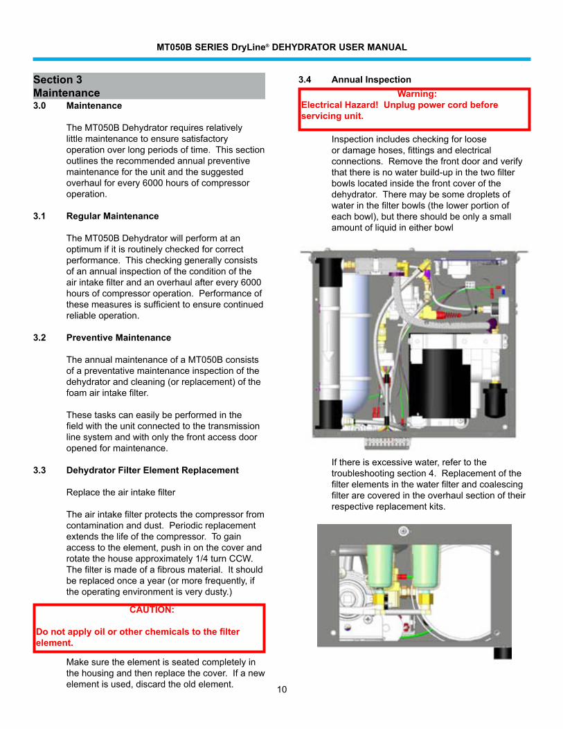
3.4 Annual Inspection Warning:Electrical Hazard! Unplug power cord before servicing unit.
Inspectionincludescheckingforlooseordamagehoses,fittingsandelectricalconnections.Removethefrontdoorandverifythatthereisnowaterbuild-upinthetwofilterbowlslocatedinsidethefrontcoverofthedehydrator.Theremaybesomedropletsofwaterinthefilterbowls(thelowerportionofeachbowl),butthereshouldbeonlyasmallamountofliquidineitherbowl
Makesuretheelementisseatedcompletelyinthehousingandthenreplacethecover.Ifanewelementisused,discardtheoldelement.
Ifthereisexcessivewater,refertothetroubleshootingsection4.Replacementofthefilterelementsinthewaterfilterandcoalescingfilterarecoveredintheoverhaulsectionoftheirrespective replacement kits.
MT050B SERIES DryLine® DEHYDRATOR USER MANUAL
11
3.4.1 Check the electrical connections.
Checkthescrewatthepowerinputconnectortoensurethattheacpowercordissecurelyterminated.Checkthescrew-inalarmterminalstoensurethatallwireconnectionsaretight.
A loose or damaged connection may result in erraticoperationandunnecessarydowntime.Refertothetroubleshootingsectionifanelectrical problem is encountered.
3.4.2 Check the ground wire.
Checkthatanelectricalsafetygroundisinstalledonthestudontherearofthedehydrator.Thisconnectionpointisadjacenttothepowerinputconnector.(Itisintendedtobecustomerinstalledinthefieldtothecustomerhalosystem.)
3.4.3 Check the hour meter
Checkthehourmeterinthedisplaytohelptodeterminethedutycycleofthedehydrator.
Ifthedehydratorhasbeenrunningformorethan20%ofitsinstalledtime,checkthesystemsforleaks.Alsocheckthetimeonthemetertodetermineifitistimetoperformthe6000–houroverhaul.
3.5 Parts Replacement and Dehydrator Overhaul
COMMSCOPEMT050BDehydratorsaredesignedtogivemanyyearsoftrouble-freeserviceandrequireveryminimalmaintenance.Thedehydratorcontains,asastandardfeature,anelectronichourmeterthatrecordscompressorrunhours.Toensurecontinuousandreliableoperation,thedehydratormustbeoverhauledevery6000hoursofcompressoroperation.Theoverhaulkit,listedbelow,containsallofthenecessarypartstoperformthisoverhaul.Thedehydratoroverhaulkitincludespartstooverhaulthecompressorandcriticalcomponentsinthedehydratorthatoftenbecomewornovertime.
3.5.1 In Case Of Difficulty:
Ifthedehydratorisnotoperating,refertoSection 2 on Installation and Section 4 on Troubleshootingtheunit.
3.5.2 Tools
Thefollowingtoolsareusedinthemaintenanceandoverhaulprocedures.
• Adjustableopen—endwrench
• Allenwrench5/32
• #2Phillipsscrewdriver
• Smallflat-bladescrew-driver
3.5.3 Overhaul Procedure
WhentheMT050Bcompressorruntimereaches6000hours(oramultipleof6000hours)itistimetoreplacecertainitemsinthecompressorandtheairpathofthedehydrator.Theseincludethepistoncups,pistonsealsandheadgasketsofthecompressor,thefilterelementsinthewaterandcoalescingfilters,andthetubesectionconnectingthecompressoroutputtothecoalescingfilterinput.
3.5.4 Unit Shutdown and Removal
InordertoperformanoverhaulontheMT050B,theunitmustbeturnedoffandremovedfromservice.Asthisisbeingdone,thelowpressurealarmmayactivethroughareportingalarmsystem.Personnelmonitoringsuchanalarmshouldbenotifiedinadvancesothattheyareawareofthefactthatserviceisbeingperformed.Itisalsonecessarytodisconnectthedehydratordryairoutputfromthewaveguidesystemduringtheoverhaul.
MT050B SERIES DryLine® DEHYDRATOR USER MANUAL
12
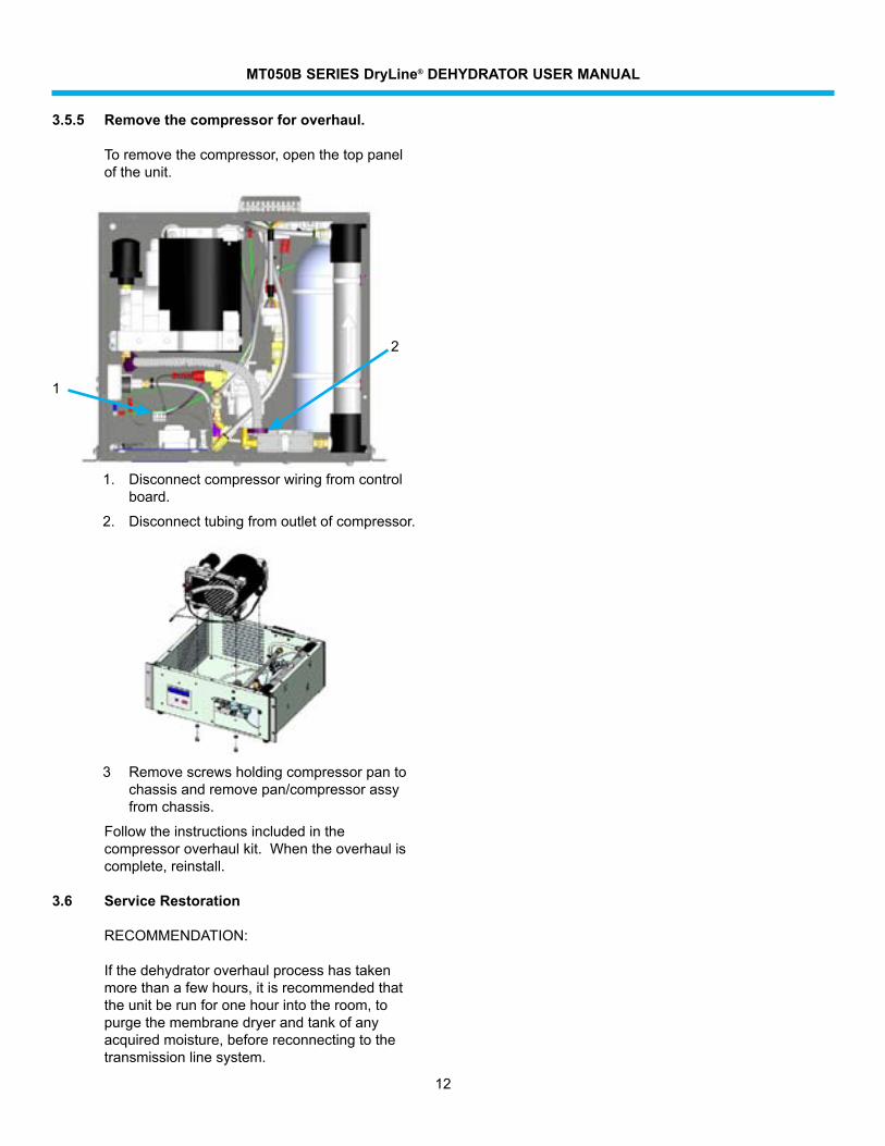
3.5.5 Remove the compressor for overhaul.
Toremovethecompressor,openthetoppaneloftheunit.
1. Disconnectcompressorwiringfromcontrolboard.
2. Disconnecttubingfromoutletofcompressor.
3 Removescrewsholdingcompressorpantochassisandremovepan/compressorassyfromchassis.
Followtheinstructionsincludedinthecompressoroverhaulkit.Whentheoverhauliscomplete, reinstall.
3.6 Service Restoration
RECOMMENDATION:
Ifthedehydratoroverhaulprocesshastakenmorethanafewhours,itisrecommendedthattheunitberunforonehourintotheroom,topurgethemembranedryerandtankofanyacquiredmoisture,beforereconnectingtothetransmission line system.
1
2
MT050B SERIES DryLine® DEHYDRATOR USER MANUAL
13
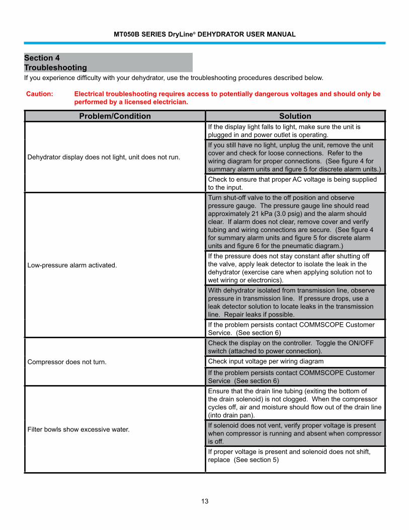
Section 4TroubleshootingIfyouexperiencedifficultywithyourdehydrator,usethetroubleshootingproceduresdescribedbelow.
Caution: Electrical troubleshooting requires access to potentially dangerous voltages and should only be performed by a licensed electrician.
Problem/Condition Solution
Dehydratordisplaydoesnotlight,unitdoesnotrun.
Ifthedisplaylightfallstolight,makesuretheunitispluggedinandpoweroutletisoperating.Ifyoustillhavenolight,unplugtheunit,removetheunitcoverandcheckforlooseconnections.Refertothewiringdiagramforproperconnections.(Seefigure4forsummaryalarmunitsandfigure5fordiscretealarmunits.)ChecktoensurethatproperACvoltageisbeingsuppliedtotheinput.
Low-pressurealarmactivated.
Turnshut-offvalvetotheoffpositionandobservepressuregauge.Thepressuregaugelineshouldreadapproximately21kPa(3.0psig)andthealarmshouldclear.Ifalarmdoesnotclear,removecoverandverifytubingandwiringconnectionsaresecure.(Seefigure4forsummaryalarmunitsandfigure5fordiscretealarmunitsandfigure6forthepneumaticdiagram.)Ifthepressuredoesnotstayconstantaftershuttingoffthevalve,applyleakdetectortoisolatetheleakinthedehydrator(exercisecarewhenapplyingsolutionnottowetwiringorelectronics).Withdehydratorisolatedfromtransmissionline,observepressureintransmissionline.Ifpressuredrops,usealeakdetectorsolutiontolocateleaksinthetransmissionline.Repairleaksifpossible.IftheproblempersistscontactCOMMSCOPECustomerService.(Seesection6)
Compressor does not turn.
Checkthedisplayonthecontroller.ToggletheON/OFFswitch(attachedtopowerconnection).Checkinputvoltageperwiringdiagram
IftheproblempersistscontactCOMMSCOPECustomerService(Seesection6)
Filterbowlsshowexcessivewater.
Ensurethatthedrainlinetubing(exitingthebottomofthedrainsolenoid)isnotclogged.Whenthecompressorcyclesoff,airandmoistureshouldflowoutofthedrainline(intodrainpan).Ifsolenoiddoesnotvent,verifypropervoltageispresentwhencompressorisrunningandabsentwhencompressorisoff.Ifpropervoltageispresentandsolenoiddoesnotshift,replace(Seesection5)
MT050B SERIES DryLine® DEHYDRATOR USER MANUAL
14
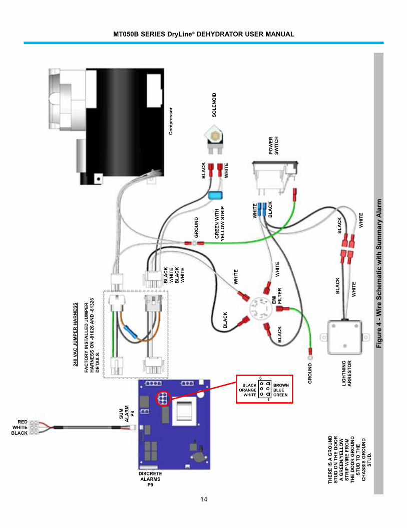
Figu
re 4
- W
ire S
chem
atic
with
Sum
mar
y A
larm
Com
pres
sor
REDWHITE BLACK
SUM
A
LAR
MP8
DISCRETE ALARMS
P9
GR
OU
ND
THER
E IS
A G
RO
UN
D
STU
D O
N T
HE
DO
OR
A
GR
EEN
/YEL
LOW
ST
RIP
WIR
E FR
OM
TH
E D
OO
R G
RO
UN
D
STU
D T
O T
HE
CH
ASS
IS G
RO
UN
D
STU
D.
POW
ER
SWIT
CH
BLA
CK
WH
ITE
GR
EEN
WIT
H
YELL
OW
STR
IP
SOLE
NO
ID
BLA
CK
WH
ITE
1
6
BROWNBLUEGREEN
BLACKORANGE
WHITE
GR
OU
ND
EMI
FILT
ER
240
VAC
JU
MPE
R H
AR
NES
S
FAC
TORY
INST
ALL
ED J
UM
PER
H
AR
NES
S O
N -8
1026
AN
D -8
1326
D
ETA
ILS.
WH
ITE
WH
ITE
WH
ITE
WH
ITE
BLA
CKB
LAC
K
BLA
CK
BLA
CK
BLA
CK
WH
ITE
BLA
CK
WH
ITE
LIG
HTN
ING
A
RR
ESTO
R
MT050B SERIES DryLine® DEHYDRATOR USER MANUAL
15
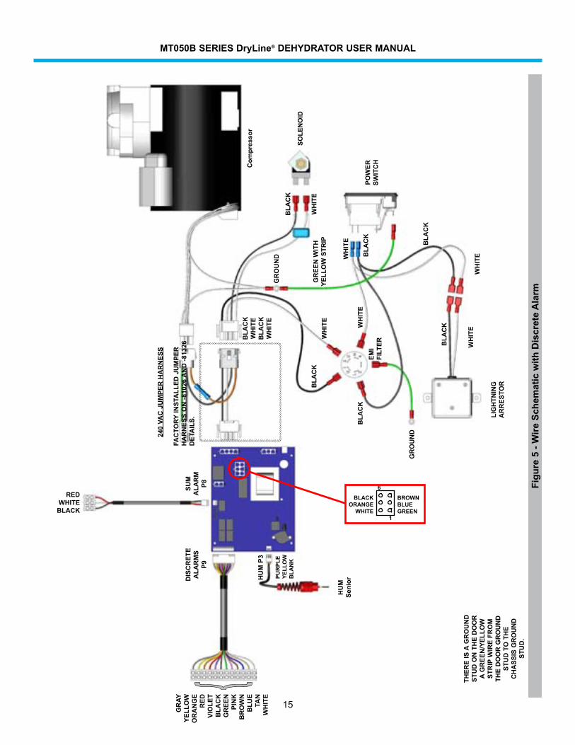
Figu
re 5
- W
ire S
chem
atic
with
Dis
cret
e A
larm
Com
pres
sor
HU
M
Seni
orHU
M P
3
}
GR
AYYE
LLO
WO
RA
NG
ER
EDVI
OLE
TB
LAC
KG
REE
NPI
NK
BR
OW
NB
LUE
TAN
WH
ITE
SUM
A
LAR
MP8
DIS
CR
ETE
ALA
RM
SP9
GR
OU
ND
THER
E IS
A G
RO
UN
D
STU
D O
N T
HE
DO
OR
A
GR
EEN
/YEL
LOW
ST
RIP
WIR
E FR
OM
TH
E D
OO
R G
RO
UN
D
STU
D T
O T
HE
CH
ASS
IS G
RO
UN
D
STU
D.
POW
ER
SWIT
CH
BLA
CK
WH
ITE
GR
EEN
WIT
H
YELL
OW
STR
IP
SOLE
NO
ID
BLA
CK
WH
ITE
1
6
BROWNBLUEGREEN
BLACKORANGE
WHITE
PUR
PLE
YELL
OW
BLA
NK
GR
OU
ND
EMI
FILT
ER
240
VAC
JU
MPE
R H
AR
NES
S
FAC
TORY
INST
ALL
ED J
UM
PER
H
AR
NES
S O
N -8
1026
AN
D -8
1326
D
ETA
ILS.
REDWHITE BLACK
WH
ITE
WH
ITE
WH
ITE
WH
ITE
BLA
CK
WH
ITE
BLA
CK
WH
ITE
BLA
CK
BLA
CK
BLA
CK
BLA
CK
LIG
HTN
ING
A
RR
ESTO
R
MT050B SERIES DryLine® DEHYDRATOR USER MANUAL
16
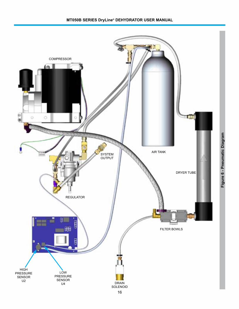
Figu
re 6
- Pn
eum
atic
Dia
gram
HIGHPRESSURE
SENSOR U2
LOWPRESSURE
SENSOR U4
SYSTEMOUTPUT
DRAIN SOLENOID
FILTER BOWLS
DRYERTUBE
COMPRESSOR
AIRTANK
REGULATOR
MT050B SERIES DryLine® DEHYDRATOR USER MANUAL
17
Section 6Customer Service6.0 Introduction
COMMSCOPEprovidesin-warrantyandout-of-warrantyrepairsaswellasdehydratorandcompressoroverhaulsfromseveralRepairCenters.CoordinationoftheseservicesisprovidedthroughthenearestSalesOfficeorCustomerServiceCenter.TheCenterisalsopreparedtohelpyouwiththefollowing:
• TechnicalAssistance
• Troubleshooting
• Repairs
• Loaner Units
• Spare Parts
• InstallationMaterials
• System Accessories
6.1 In Case of Trouble
Thefirststepyoushouldtakeiftroubledevelopsusingadehydratoristoreadtheoperatorsmanualandfollowthetroubleisolatingprocedures given in it.
Ifthestepsinthemanualdonotidentifyandremedytheproblem,thencontactanCOMMSCOPECustomerServiceCenterfor24–hourtelephoneassistance.RecordtheModelNumber(e.g.MT050B)andSerialNumberfromtheproductlabel,asyouwillbeaskedforthesewhenyoucall.Twomainlocationsarecurrentlyavailabletohelp:
FromNorthAmerica Telephone:1-800-255-1479 Fax(U.S.A.):1-800-349-5444
International Telephone:+1-779-435-6500 FaxNumber:+1-779-435-8579
Web Access Internet: www.commscope.com email: #[email protected]
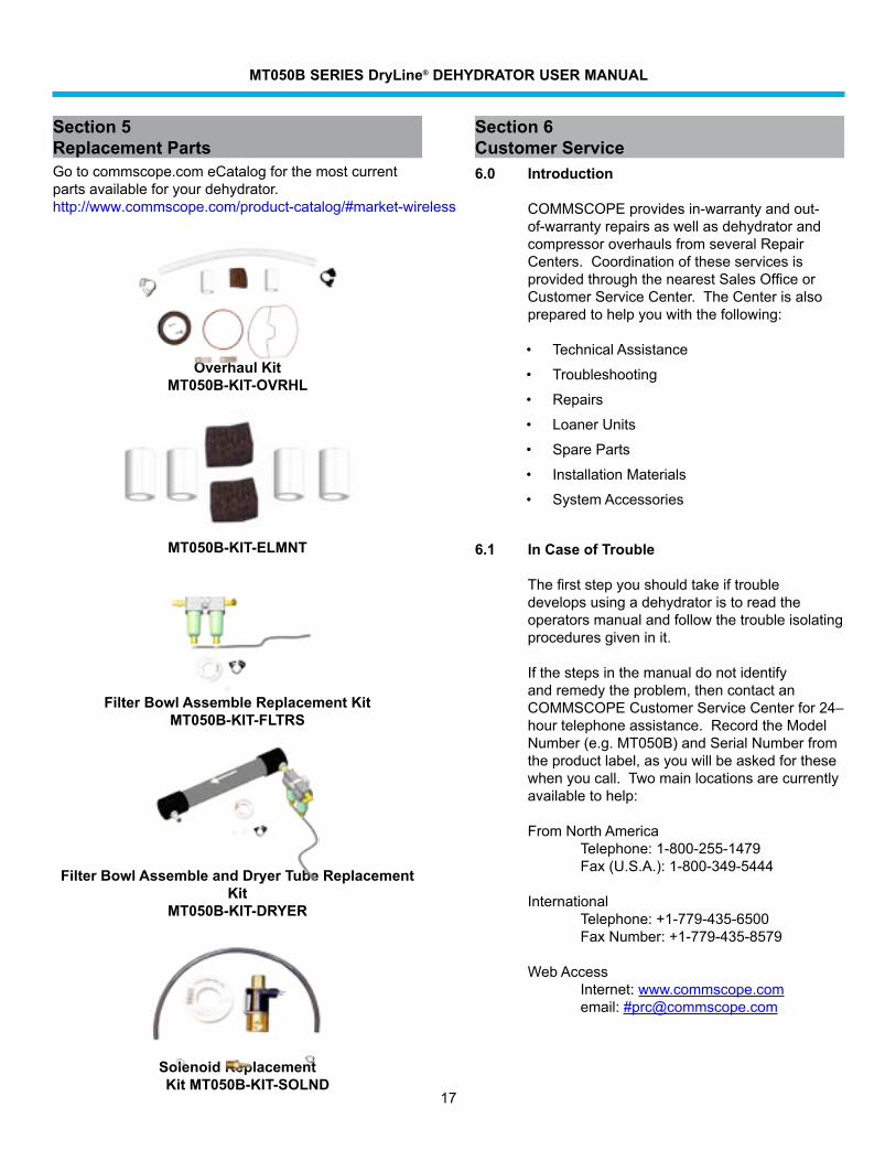
Section 5Replacement PartsGotocommscope.comeCatalogforthemostcurrentpartsavailableforyourdehydrator.http://www.commscope.com/product-catalog/#market-wireless
Overhaul KitMT050B-KIT-OVRHL
Filter Element Replacement KitMT050B-KIT-ELMNT
Filter Bowl Assemble Replacement KitMT050B-KIT-FLTRS
Filter Bowl Assemble and Dryer Tube Replacement Kit
MT050B-KIT-DRYER
Solenoid Replacement Kit MT050B-KIT-SOLND
MT050B SERIES DryLine® DEHYDRATOR USER MANUAL
18
6.2 Initial Steps by COMMSCOPE
Whenyourcallorfaxcommunicationisreceived,theCOMMSCOPEstaffwillworkwithyoutopinpointthepossiblecauseoftrouble.Ifthepressurizationequipmentissuspect,theywill:
• askforyourunitModelNumberandSerialNumber
• checkthewarrantystatusoftheunit
• advisetheavailabilityofaloanerunit
• provideanestimateofthecostforinspectionandrepairs,iftheunitisout–of–warranty
• faxaReturnMaterialAuthorizationSheettoyou.
6.3 Repair Center Process
A method of Payment must be provided prior to issuing of RMA regardless of warranty status.
IN–WARRANTY REPAIR:MostCOMMSCOPEpressurizationproductscarryawarrantyofonetothreeyears,dependinguponmodelnumber.Warrantydetailsareavailableonourwebpage.Ifyourunitfallswithinitswarrantyperiod,inspectionandrepairswillbeperformedatnochargeandtheunitwillbepromptlyreturnedtoyou.Ifawarrantyunitisdeemednoproblemfoundaninspectionfeeandfreightwillbechargedtothecustomer.
OUT–OF–WARRANTY REPAIR:Wewillinformyouwiththecostofrepairandobtainyourapprovaltoproceedwithrepairsor,ifyouelectnottohavetheunitrepaired,yourinstructionsondispositionofyourunit.Whenrepairsarecomplete,wewillreturnyourunitandinvoiceyoufortheinspectioncharge,materialsusedfortherepairandlaborappliedtocompletetherepair.Ifyouelectednottorepairtheunit,wewillinvoiceyoufortheinspectionandfreightchargeifunitistobereturned.
LOANER UNITS: Loaner units are available fromtherepaircentertomaintainyoursystemwhilerepairsarebeingperformed.Ifyoufeelyou need a loaner, please contact us at one ofthenumberslistedundercontactnumbers.AP.O.forthefullvalueoftheunitmustbeissuedpriortoshipment.Alsocontactuswhentheloanerisreadytobereturnedsothatwe
canissueaNEWRMAnumbertoidentifyyourreturnandcreatetheappropriatecredittoyouraccount.DamagestoloanerwillbedeductedfromtheP.O.
PACKING INSTRUCTIONS: Pack your unit securelyforshipmenttotheRepairCenter.Ifyoureceivedaloanerunit,wesuggestyouusetheboxandpackingmaterialstoreturnyourunit.Otherwisewehavefactorypackingmaterialsavailableforanominalfee.EncloseacompletedcopyofthisforminsidetheboxandclearlymarkyourCompanyNameandRMA:XXXXXXXonoutsideofthebox.AddresstheboxtothefollowingShip–ToAddress:
COMMSCOPEPRESSURIZATIONSERVICECENTERRMA#XXXXXXX11312 S. PIPELINE RD.EULESS,TX.76040-6629
Please note, Units received with Biological/animal contamination will be returned unrepaired or scraped after notification and you will be invoiced for inspection and freight.
CONTACT NUMBERS:Ifyouhaveanyquestionsabouttherepairprocessorstatusofyourunit,pleasecontactusdirectlythroughoneofthefollowingmethods–Telephone(below)
TEL: 817-864-4150 817-864-4155
FAX: 817-864-4179
6.4 RoHS Inquiries ForinquiriesonRoHSpleasecontactthefollowing: CommScope Inc. Corke Abbey, Bray Co., Dublin, Ireland Attn: Legal Department
MT050B SERIES DryLine® DEHYDRATOR USER MANUAL
19
Section 7DC Inverter Option7.1 Introduction
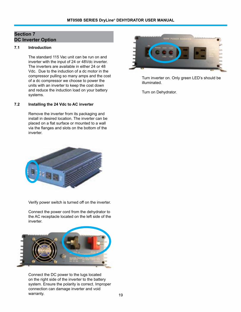
Thestandard115Vacunitcanberunonandinverterwiththeinputof24or48Vdcinverter.Theinvertersareavailableineither24or48Vdc.Duetotheinductionofadcmotorinthecompressorpullingsomanyampsandthecostofadccompressorwechoosetopowertheunitswithaninvertertokeepthecostdownandreducetheinductionloadonyourbatterysystems.
7.2 Installing the 24 Vdc to AC inverter
Removetheinverterfromitspackagingandinstallindesiredlocation.Theinvertercanbeplacedonaflatsurfaceormountedtoawallviatheflangesandslotsonthebottomoftheinverter.
Verifypowerswitchisturnedoffontheinverter.
ConnectthepowercordfromthedehydratortotheACreceptaclelocatedontheleftsideoftheinverter.
ConnecttheDCpowertothelugslocatedontherightsideoftheinvertertothebatterysystem.Ensurethepolarityiscorrect.Improperconnection can damage inverter and void warranty.
Turninverteron.OnlygreenLED’sshouldbeilluminated.
TurnonDehydrator.
MT050B SERIES DryLine® DEHYDRATOR USER MANUAL
20
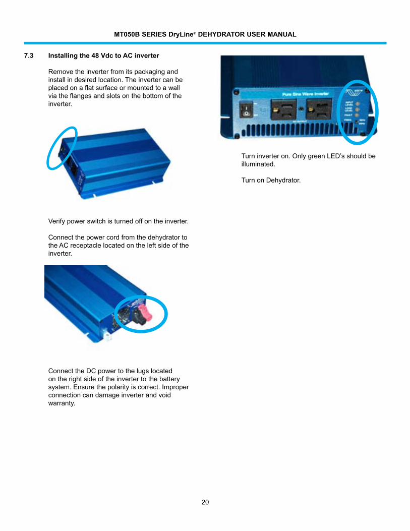
7.3 Installing the 48 Vdc to AC inverter
Removetheinverterfromitspackagingandinstallindesiredlocation.Theinvertercanbeplacedonaflatsurfaceormountedtoawallviatheflangesandslotsonthebottomoftheinverter.
Verifypowerswitchisturnedoffontheinverter.
ConnectthepowercordfromthedehydratortotheACreceptaclelocatedontheleftsideoftheinverter.
ConnecttheDCpowertothelugslocatedontherightsideoftheinvertertothebatterysystem.Ensurethepolarityiscorrect.Improperconnection can damage inverter and void warranty.
Turninverteron.OnlygreenLED’sshouldbeilluminated.
TurnonDehydrator.