mst s c - guiducci utensili · full lineup of mst series slot mills ※ adjustable between 14mm and...
TRANSCRIPT

MST SLOTTING CUTTER
Full range from 1.6 to 23.3mm in 3 types
MSTA MSTB MSTC
For narrow groove• Self-clamping type• Slot Width 1.6~4.0mm•
For middle groove• Semi-adjustable type• Slot Width 6.0~13.0mm•
For wide groove• Full-adjustable type• Slot Width 14.0~23.3mm•
TZE00043

1
Self-clamping Slot Mills MSTA Slot Mills have simple self-clamping system toallow for easy attachment by just installing the insert.
Highly rigid clamping system Holders achieve high operability through the stopper highlyrigid clamping system and achieve stable slotting by maintaining an accurate edge position.
2 Prism Clamping systemHigh replacement precision due to the clamping system with two prisms.
Easy replacement The replacement of inserts is easy and quick by using special wrench.
MSTA
1.6 2.2 3 4 6 8 10 12 14 16 18 20 22 24 Slot width (mm)
Type Applicable Insert Feature
MSTA 1.6mm - 4mm fixed
18mm - 23.3mm fully adjustable
6mm - 13mm semi adjustable
14mm - 18mm fully adjustable
Up-right type / semi-adjustable groove width
Easy and secure screw holding MSTB Slot Mills are a very simple form used to screw clamp inserts.
Inserts have four edge and are, therefore, cost-effective
Note : Inserts for 6mm slotting width has two edges.
Applicable to a variety of slotting by choosing different insertsBy changing the thickness of inserts, it's applicable to various slotting widths up to max 1mm in 0.5mm increments.
Slot width 1.6 2.2 3.0 4.0mm
Slot width 6.0~13.0mm
Full lineup of MST Series Slot Mills
※ Adjustable between 14mm and 18mm
※ Adjustable between 18mm and 23.3mm
Type SLT..
LNEU12..
SP..10T3..
SD..1204...
MSTB Type
MSTC Type
※ Adjustable in 0.5mm increments between 6mm and 13mm with the combination of inserts
Wrench is not attached. Please purchase separately.

2
Shell Mount for half-side cutting
Right hand Left hand
Applicable to various slotting needs. Slotting widths: 14.0mm to 23.3mm.Cutter diameters: 100mm to 160m.
Wide range corner R repertories are suitable for various work.
Smooth slotting width adjustment can be available by unique cam style adjustment mechanism.
Four-edges inserts that are cost-effective.
By wiper edge insert, excellentsurface finish can be expected.
By abundant insert geometry and grades, applicable for various type of workpiece machining.
Lay-down type / fully adjustable slot width
MSTC Slot width 14.0~23.3mm
Symbol
SB
SD
SE
Rake Angle
20°
15°
5°
Insert ■ Features of Insert GradesCA0835・TiN+TiCN+Al2O3 based CVD coating・For carbon steel, alloy steel, stainless steel and nodular cast iron・For middle to high speed cutting
PR0725・TiN+TiCN+TiN based PVD multi layer coating・ For carbon steel, alloy steel, stainless steel, heat resistant alloy and nodular cast iron・For middle speed cutting
PR0110・ TiB2 based PVD coating・For non ferrous metal such as aluminum alloy (Si<10%) and titanium alloy・For high speed cutting
Shape

3
MSTA Type
MSTA
MSTA
MSTA
MSTA
●●●●●●●●●●●●●●●●●●●
●: Std Stock
Fig.2
Fig.1
Fig.3
DR16-32A
DR16-32B
DR16-38
DR22-46
DR32-55
DR40-80
63N16-5T 80N16-7T100N16-9T125N16-11T 63N22-5T 80N22-7T100N22-9T125N22-11T160N22-14T 63N30-4T 80N30-6T100N30-9T125N30-11T160N30-14T 63N40-4T 80N40-6T100N40-9T125N40-11T160N40-14T
Drive Ring (mm spec)
ApplicableToolholder
StockShape Shape
Dimension (mm)
Description
●
●
●
●
●
●
32
38
46
55
80
16
22
32
40
8
10
12
4.1
6.1
8.1
10.1
3
4
5
6
12
■ Identification System
Slot Mill with Self-Clamping System
Cutting Dia. Neutral Edge Width No. of Insert
MSTA ○○○ N ○○○ - ○○ T
Slotting Cut-offSlotting
MSTA
MSTA
MSTA
MSTA
MSTA
MSTA
63N16-5T63N22-7T63N30-4T63N40-4T
80N - T
100N - T
125N - T
160N - T
Wrench and Drive Ring are sold 1 pieace per 1 box.
Attach the drive ring (sold separately) to MSTA type slot mill to use. Drive ring is sold per single quantity. Please purchase two drive rings per one MSTA type slot mill.Do not exceed the max revolution.Do not operate cutting on reverse revolution.Wrench (MS-FRW1) is not attached. Please purchase separately.
12.3.4.
Note)
〈 MSTA Type Slot Mill
Drive Ring (Sold Separately)Assembly example
1.6
2.2
3.0
4.0
15212735152127354015212735401521273540
579
11579
1114469
1114469
1114
6380
1001256380
1001251606380
1001251606380
100125160
16
2232
16
223240
16
223240
16
223240
1.3
1.8
2.4
3.4
0.030.040.070.1
0.030.050.080.120.3
0.050.080.130.2
0.350.060.1
0.150.250.4
SLT16…
SLT22…
SLT30…
SLT40…
5,1004,0003,2002,6005,1004,0003,2002,6002,0005,1004,0003,2002,6002,0005,1004,0003,2002,6002,000
Max.Revolutionmin-1
ApplicableInsertSee P5
Toolholder Dimension
StockNo.ofInsert
Weight(kg)
Dimension (mm)EdgeWidth
SlotDepth
Description
Spare parts
Wrench
Reco
mm
ende
d C
uttin
g C
ondi
tion
Exam
ple
of
App
licab
le A
rbor
MS-FRW1
Wrench is not attached. Please purchase separately.Set up see P5.
See P5 See Back Page
●: Std Stock
MSTA
Toolholder

CA0835
PR0735Shape
Dimension (mm)
Ref.
Page
for T
oolh
olde
r
Angle (° )
Classification of usage
CVDCoatedcarbide
PVDCoatedcarbide
Description
●: 1s t Choice
○:2nd Choice
Carbon Steel Alloy Steel
Stainless Steel
Cast Iron
Non-ferrous Material
Heat-Resistant Alloy
Titanium Alloy
0.15
0.2
0.15
0.2
5°
15°
SLT
SLT
Insert Description
■ SLT Type
■ Insert Identification System
■ Features of Insert Grades
1.6
2.2
3.0
4.0
1.6
2.2
3.0
4.0
16-15SKB
22-20SKB
30-20SKB
40-20SKB
16-15SKD
22-20SKD
30-20SKD
40-20SKD
CA0835
PR0735
・ TiN+TiCN+Al2O3 based CVD coated carbide
・For carbon steel, alloy steel, stainless steel and nodular cast iron
・For middle to high speed cutting
・ TiN based PVD coated carbide
・ For stainless steel and heat resistant alloy
・ For low to middle speed cutting
Low Cutting Force
① ② ③ ④ ⑤S L T 16 15 S- KB
⑤Chipbreaker Symbol
④Edge Prep.
Corner-R
②Edge Width
①Insert Symbol
Symbol Symbol SymbolEdge Width
16
22
1.6mm
2.2mm
15
20
0.15mm
0.2mm
Symbol Cuttig Edge Spec.
S
KB
KD
Rake Angle
③Corner-R(r )
Chamfer+R-honed
●: Std Stock
+0- 0.1
+0.08- 0.05
+0.15- 0
+0.15- 0
+0- 0.1
+0.08- 0.05
+0.15- 0
+0.15- 0
●
●
●
●
●
●
●
●
●
●
●
●
●
●
●
●
Inserts are sold in 10 piece per 1 box.
● Chipbreaker SelectionKB・・・Conventional chipbreaker for steel and cast iron.KD・・・Low cutting force chipbreaker for stainless steel.
4
P3
MSTA

Insert removal hole for Wrench
Wrench support hole
Workpiece Material Hardness(HB)
Recommended Grade (Vc:m/min) Feed per tooth fz (mm/t)
CVD coated carbide
CA0835 PR0735 1.6 2.2 3.0 4.0
PVD coated carbide
Low-carbon Steel
Carbon Steel
Alloy Steel
High-carbon Alloy
Stainless Steel
Nodular Cast Iron
Gray Cast Iron
Recommended Cutting Condition
■ Set up
Note) Use appropriate wrench for set up
How to attach inserts
How to detach inserts
Put insert inside the slot mill.Insert one of the pin on the wrench (on IN indicated side) into the wrench support hole.Using the other pin, push the front relief surface of the insert.Rotate the wrench until insert's back end makes contact with slot mill.
1.2.
3.
4.
Insert one of the pin on the wrench (on OUT indicated side) into the wrench support hole, and insert other pin into the hole on releasing wrench.Insert can be uninstalled by rotating the wrench counter clock wise.(A magnet is installed out side)
1.
2.
125
190
250
180
275
280
220
300
260
160
250
IN indication example
OUT indication example
250 310
160 190
140 180
140 180
120 160
100 140
150 190
140 180
160 200
130 160
110 140
Use down-cut machining.If D.O.C(ap) is under 1/10 of Cutter Dia D , it is possible to increase feed per tooth(fz) 40%.
1. 2.
Note)
Edge width (mm)Remarks
with coolant
withoutcoolant
250
160
150
150
130
120
120
80
200
130
110
110
100
80
80
60
0.03 0.12
0.03 0.12
0.03 0.12
0.03 0.12
0.03 0.10
0.03 0.10
0.03 0.10
0.03 0.10
0.03 0.12
0.03 0.12
0.03 0.12
0.04 0.14
0.04 0.14
0.04 0.14
0.04 0.14
0.04 0.12
0.04 0.12
0.04 0.12
0.04 0.12
0.04 0.14
0.04 0.14
0.04 0.14
0.06 0.18
0.06 0.18
0.06 0.18
0.06 0.18
0.06 0.16
0.06 0.16
0.06 0.16
0.06 0.16
0.06 0.18
0.06 0.18
0.06 0.18
0.08 0.20
0.08 0.20
0.08 0.20
0.08 0.20
0.08 0.18
0.08 0.18
0.08 0.18
0.08 0.18
0.08 0.20
0.08 0.20
0.08 0.20
MSTA
ap
5
MSTA

MSTB
MSTB
MSTB
MSTB
80AN0607-4T100AN0607-5T125AN0607-6T160AN0607-8T 80AN0809-4T100AN0809-5T160AN0809-8T125AN1011-4T160AN1011-5T160AN1213-5T
Max.Revolution
min-1
StockNo.ofInsert Weight
(kg)
Dimension (mm)Edge Width(mm)Slot
Depth
DescriptionNo.ofEdgeLine
A: Without BossS: With Boss
mm spec
Slot Mill with Up-right Insert
Cutting Dia.
N: Neutral
Edge WidthNo. of
Edge Line
MSTB ○○○ A N ○○ ○○ - ○ T
6
8
10
12
7
9
11
13
152128
45.51622
45.530
47.548.5
81012168
1016121515
4568458455
8010012516080
100160125160160
2732
40
2732
40
4452
63
4452
63
12
0.30.40.71.10.40.51.30.91.61.6
●●●●●●●●●●
■ Identification System 〈MSTB Type Slot Mill
Slotting Cut-offSlotting
29.834.8
43.5
29.834.8
43.5
78
10
78
10
9,2408,2707,3906,5409,2408,2706,4507,3906,4506,450
Toolholder Dimension
Arbor Mount
In order to use more than two slot mills of combination, there are two key slots on the slot mill itself.
● Std. Stock
6
MSTB
Toolholder

MSTB
MSTB
MSTB
MSTB
MSTB
MSTB
MSTB
●●●●●●●●
80SN0607-4T100SN0607-5T160SN0607-8T 80SN0809-4T100SN0809-5T160SN0809-8T125SN1011-4T160SN1011-5T
Spare Parts
Stock
Dimension (mm)Edge Width(mm) SlotDepth
Description
Description ApplicableInsert
Without Boss
With Boss
mm
spe
c
Coat anti-seize compound (MP-1) thinly on clamp screw when insert is fixed.MP-1MP-1
Spare Parts
WrenchClamp Screw Anti-seize Compound Mounting Bolt
6
8
10
7
9
11
1621411621412643
810168
10161215
45845845
8010016080
100160125160
2227402227
40
4050704050
70
AN0607- TAN0809- TAN1011- T
160AN1213-5T80SN0607-4T100SN0607-5T160SN0607-8T80SN0809-4T100SN0809-5T160SN0809-8T
SN1011- T
SE-40050TR
SE-40068TR
SE-40090TR
SE-40050TR
SE-40068TR
SE-40068TR
TT-15L
TT-15L
MP-
MP-
HH10X35HH12X35HH20X40HH10X35HH12X35HH20X40HH20X40
■ Spare Parts and Applicable Insert
2324282324
28
6.379
6.37
9
10.412.416.410.412.4
16.4
1820331820
33
1214221214
22
0.71.01.90.81.22.22.02.5
9,2408,2706,5409,2408,2706,5407,3906,540
Max.Revolution
min-1
Weight(kg)
Toolholder Dimension
Shell Mount
H(min) dimension shows in case of minimum of edge width.1. Note)
Recommended Cutting Condition
Example of Applicable Arbor
No.ofInsert
No.ofEdgeLine
50
● Std. Stock
MP-1MP-1
HW
Ad2d1
aE
D
T
7
See Back PageSee P8, P9 See P10
MSTB
Toolholder

■ LN型 LN type
⑤
Applicable Insert
Shape
Dimension (mm)
Description No.of Edge
Carbon Steel Alloy Steel
Stainless Steel
Cast Iron
Non-ferrous Material
Heat-Resistant Alloy
Titanium Alloy
(mm)
Description
LNEU12 12.7 9.6 4.4
LNEU
LNEU
■ LN Type
3.5
4.0
4.5
5.0
5.5
6.0
0.3
0.8
0.4
0.8
0.4
0.8
0.4
0.8
0.4
SE-40050TR
SE-40055TR
SE-40068TR
SE-40080TR
SE-40090TR
SE-40100TR
SE-40050TR
SE-40068TR
SE-40080TR
○○○ ○
○○○ ○
○○○ ○
○○○ ○
○○○ ○
○○○ ○
○○○ ○
1235-03
1240-08
1245-04
1245-08
1250-04
1250-08
1255-04
1255-08
1260-04
2
2
4
4
4
4Re
f. Pa
ge fo
r Too
lhol
der
Ref.
Page
for R
ecom
men
ded
Cut
ting
Con
ditio
n
■ Features of Insert GradesPR0725・TiN+TiCN+TiN based PVD multi layer coated carbide
・For carbon steel, alloy steel, stainless steel, heat resistant alloy and nodular cast iron
・For middle speed cutting
1235-03S
1245-04S
1245-08S
1250-04S
1250-08S
2
4
4
3.5
4.5
5.0
0.3
0.4
0.8
0.4
0.8
Classification of usage
■ Insert Identification System
① ② ③ ④ ⑤L N E U 12 35 03- S
②Insert Length
①Insert Symbol
Symbol Insert Length
12 12.7mm
Edge Width
Symbol SymbolEdge Width
35
40
3.5mm
4.0mm
03
04
0.3mm
0.4mm
④Edge Prep.
Symbol Cuttig Edge Spec.
S Chamfer+R-honed
Corner-R
Corner-R(r )
●: 1s t Choice
○: 2nd Choice
PR0725
●
●
●
●
●
●
●
●
●
App
licab
le C
lam
p Sc
rew
●
●
●
●
●
PVDCoatedcarbide
③
●:Std Stock
Inserts are sold in 10 piece per 1 box.
Tough Edge
Edge detail
Honed
LNEU1235-03 1240-08
LNEU1235-03S
Edge detail
Please select the applicable clamp screw depending on each insert description.See page 10 for insert description and applicable clamp screw depending on edge width.
1. 2.
Note)
8
P10P6P7
MSTB

SE-40050TR
SE-40055TR
SE-40068TR
SE-40080TR
SE-40068TR
SE-40080TR
SE-40090TR
SE-40100TR
Applicable Insertmm inch(mm)
Edge Width A Line B Line C Line
DescriptionClamp ScrewApplicable Insert Clamp ScrewApplicable Insert Clamp Screw
Clamp Screw(Standard
attachment parts)
Wrench TighteningTorque
(Nm)For ClampScrew
■ Combination of applicable insert
■ Slot width (edge width) adjustment
66.578
8.59
1010.51112
12.513
LNEU1245..
LNEU1250..
LNEU1255...
LNEU1260...
SE-40068TR
SE-40080TR
SE-40090TR
SE-40100TR
1.
2.
3.
4.
In the case of MSTB AN0607- T
the width (W) is 6mm by installing LNEU1235 on both A line and C line.
By replacing C line only with LNEU1240 the width (W) is 6.5mm.
By replacing A line and C line with LNEU1240 the width (W) is 7mm.
If the slotting width edge width is 10mm (.375"), the B line (middle edge) is necessary.
The Slot width (edge width) of MSTB-Type slot Mills is adjustable by a maximum of 1mm (.039 ” ) with the combination of inserts.
1)
2)3)
There is no description such as "A line", "B line", and "C line" on the actual slot Mill. These are only for explanation of the combination of insert.Use proper clamp screws for applicable inserts on the basis of the above chart.
Please do not use, that has a difference of width more than 1mm (.039”).
Note
1 2 3 4
MSTB
MSTB
MSTB
MSTB
SE-40050TR
SE-40068TR
SE-40068TR
SE-40090TR
LNEU1235..
LNEU1240..
LNEU1245..
LNEU1250..
LNEU1245..
LNEU1250..
LNEU1255...
LNEU1260...
SE-40050TR
SE-40055TR
SE-40068TR
SE-40080TR
SE-40068TR
SE-40080TR
SE-40090TR
SE-40100TR
LNEU1235..
LNEU1240..
LNEU1245..
LNEU1250..
LNEU1245..
LNEU1250..
LNEU1255...
LNEU1260...
○○○○○○AN0607-○T
○○○○○○SN0607-○T
○○○○○○AN0809-○T
○○○○○○SN0809-○T
○○○○○○AN1011-○T
○○○○○○SN1011-○T
○○○○○○AN1213-○T
3TT-15L
mm
spe
c
For clamp screw, above listed "Standard attachment parts" are attached. In case of necessity of another size of clamp screw by changing slotting width, please purchase separately.
A lineC line
A line C lineA line C lineA line C line
B line
9
MSTB
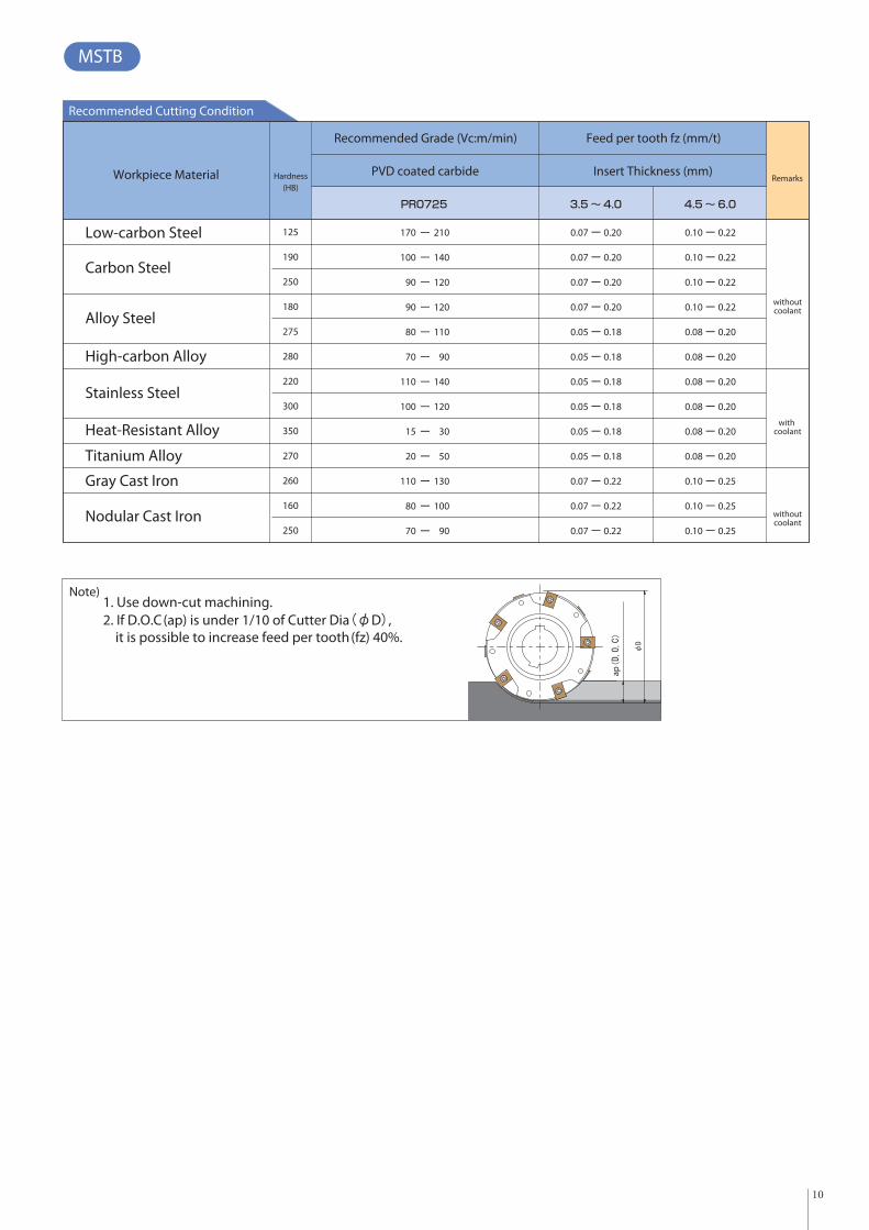
Recommended Cutting Condition
Workpiece Material Hardness(HB)
Recommended Grade (Vc:m/min) Feed per tooth fz (mm/t)
PR0725 3.5 ~ 4.0 4.5 ~ 6.0
PVD coated carbide Insert Thickness (mm)
Low-carbon Steel
Carbon Steel
Alloy Steel
High-carbon Alloy
Stainless Steel
Heat-Resistant Alloy
Titanium Alloy
Nodular Cast Iron
Gray Cast Iron
125
190
250
180
275
280
220
300
350
270
260
160
250
210
140
120
120
110
90
140
120
30
50
130
100
90
170
100
90
90
80
70
110
100
15
20
110
80
70
0.07 0.20
0.07 0.20
0.07 0.20
0.07 0.20
0.05 0.18
0.05 0.18
0.05 0.18
0.05 0.18
0.05 0.18
0.05 0.18
0.07 0.22
0.07 0.22
0.07 0.22
0.10 0.22
0.10 0.22
0.10 0.22
0.10 0.22
0.08 0.20
0.08 0.20
0.08 0.20
0.08 0.20
0.08 0.20
0.08 0.20
0.10 0.25
0.10 0.25
0.10 0.25
Remarks
with coolant
withoutcoolant
withoutcoolant
1. Use down-cut machining.2. If D.O.C(ap) is under 1/10 of Cutter Dia D , it is possible to increase feed per tooth(fz) 40%.
Note)
ap
10
MSTB

N: NeutralR: Right-handL: Left-hand
Edge Width
10 : SP..10T3..12 : SD..1204..
ApplicableInsert
Slot Mill with Lay-down type
Cutting Dia. No. of Insert
MSTC ○○○ A N ○○ ○○ - ○○- ○○ T
■ Identification System
■ Machining direction of MSTC type slot mill
〈MSTC Type Slot Mill
mm spec
A: Without Boss
S: With Boss
AN(Slotting) AL(Upper surface machining)AR(Lower surface machining)
SN(Slotting) SR(Lower surface machining) SL(Upper surface machining)
11
MSTC

MSTC
MSTC
MSTC
MSTC
●●●●●●●●●
14
16
18
21
16
18
20.7
23.3
25.934.451.934.451.934
51.534
51.5
68
108
108
108
10
345454545
100125160125160125160125160
32
40
46.8
54.8
13.9
15.9
18.2
20.8
17,25015,45013,65015,45013,65010,3509,150
10,3509,150
100AN1416-10-3T125AN1416-10-4T160AN1416-10-5T125AN1618-10-4T160AN1618-10-5T125AN1820-12-4T160AN1820-12-5T125AN2123-12-4T160AN2123-12-5T
MSTC...AN...10..MSTC...SN...10..MSTC...AN...12..MSTC...SN...12..
SP..10T3...N...
SD..1204...N...
SP..10T3...R...SP..10T3...L...SD..1204...R...SD..1204...L...
MSTC
MSTC
MSTC
MSTC
14
16
18
20.7
16
18
20.7
23.3
24.431.943.431.943.431.943.431.943.4
68
108
108
108
10
345454545
100125160125160125160125160
273240324032403240
485870587058705870
50.8
50.8
51.0
51.0
1.01.62.01.72.31.62.31.72.6
17,25015,45013,65015,45013,65010,3509,150
10,3509,150
100SN1416-10-3T125SN1416-10-4T160SN1416-10-5T125SN1618-10-4T160SN1618-10-5T125SN1820-12-4T160SN1820-12-5T125SN2123-12-4T160SN2123-12-5T
Max.Revolution
(min-1)
Toolholder Dimension
StockNo.ofInsert
0.50.81.51.01.81.01.81.22.1
Weight(kg)
Dimension (mm)Edge Width (mm) SlotDepth
DescriptionNo.ofEdgeLine
Max.Revolution
(min-1)
Toolholder Dimension
StockNo.ofInsert Weight
(kg)Shape
Dimension (mm)Edge Width (mm) SlotDepth
DescriptionNo.ofEdgeLine
Applicable Insert see P17-P18
With hand NeutralDescription Edge No. (Marked)
Location of odd NoLocation of even NoLocation of odd NoLocation of even No
Shouldering
Arbor Mount
SlottingSlotting
■ Applicable Insert
■ Spare Parts ■ Slot width (edge with) adjustment・For spare parts, see P15. ・See P20-P22.
■ Example of Applicable Arbor・See Back page.
34.8
43.5
8
10
242630263026302630
789898989
12.414.416.414.416.414.416.414.416.4
202756275627562756
1418
18
18
18
Fig.1
Fig.2Fig.1Fig.2Fig.1Fig.2Fig.1Fig.2
RecommendedCutting Conditions P19.
In case of attaching handed insert on above slottmill, same number of dege line right handed and left handed inserts are necessary.
Shell Mount
In order to use more than two slot mills of combination, there are two key slots on the slot mill itself.
●:Std Stock
●:Std Stock
●●●●●●●●●
Fig.1 Fig.2
Cutting edge No mark (All round)
Cutting edge No mark (All round)
Cutting edge No mark (All round)
H(min) dimension shows in case of minimum of edge width.1. Note)
12
MSTC
Toolholder

Dimension (mm)Description
Toolholder Dimension
Max.Revolution
(min-1)
Weight(kg)
Stock No.ofInsert
Dimension (mm)Description
Toolholder Dimension
Max.Revolution
(min-1)
Weight(kg)
Stock No.ofInsert
MSTC
MSTC
MSTC
MSTC
●●●●●●●●●
68
108
108
108
10
100125160125160125160125160
25.934.451.934.451.934.051.534.051.5
46.8
54.8
54.8
54.8
54.8
13.9
15.2
18.1
20.7
8
10
10
10
10
0.50.81.51.01.81.01.81.22.1
17,25015,45013,65015,45013,65010,3509,150
10,3509,150
100AR1416-10-6T125AR1416-10-8T160AR1416-10-10T125AR1618-10-8T160AR1618-10-10T125AR1820-12-8T160AR1820-12-10T125AR2123-12-8T160AR2123-12-10T
13.9
15.9
18.2
20.8
9.1
9.1
11.7
11.7
MSTC
MSTC
MSTC
MSTC
68
108
108
108
10
100125160125160125160125160
24.431.943.431.943.431.943.431.943.4
273240324032403240
485870587058705870
50.8
50.8
51.0
51.0
37.7
35.7
34.0
31.4
1.01.62.01.72.31.62.31.72.6
17,25015,45013,65015,45013,65010,3509,150
10,3509,150
100SR1416-10-6T125SR1416-10-8T160SR1416-10-10T125SR1618-10-8T160SR1618-10-10T125SR1820-12-8T160SR1820-12-10T125SR2123-12-8T160SR2123-12-10T
9.1
9.1
11.7
11.7
Shouldering
Shell Mount Right-hand
※ Right-hand shown
※ Right-hand shown
RecommendedCutting Conditions P19.
MSTC...AR...10..MSTC...SR...10..MSTC...AR...12..MSTC...SR...12..
SP..10T3...N...
SD..1204...N...
SP..10T3...R...
SD..1204...R...
With handDescription
■ Applicable Insert
■ Spare Parts・For spare parts, see P16. ・See P20-P22.
14.9
16.2
19.4
22.0
34.8
43.5
43.5
43.5
43.5
Shape
51.8
51.8
52.3
52.3
242630263026302630
789898989
12.414.416.414.416.414.416.414.416.4
202756275627562756
1418
18
18
18
Fig.1
Fig.2Fig.1Fig.2Fig.1Fig.2Fig.1Fig.2
Arbor Mount Right-hand
■ Slot width (edge with) adjustment
Applicable Insert see P17-P18
Neutral
■ Example of Applicable Arbor・See Back page.
In order to use more than two slot mills of combination, there are two key slots on the slot mill itself.
●:Std Stock
●●●●●●●●●
●:Std Stock
32
40
40
40
40
Fig.1 Fig.2
Cutting edge No mark (All round)
Cutting edge No mark (All round)
Cutting edge No mark (All round)
13
MSTC
Toolholder

68
108
108
108
10
100125160125160125160125160
25.934.451.934.451.934.051.534.051.5
0.50.81.51.01.81.01.81.22.1
17,25015,45013,65015,45013,65010,3509,150
10,3509,150
100AL1416-10-6T125AL1416-10-8T160AL1416-10-10T125AL1618-10-8T160AL1618-10-10T125AL1820-12-8T160AL1820-12-10T125AL2123-12-8T160AL2123-12-10T
68
108
108
108
10
100125160125160125160125160
24.431.943.431.943.431.943.431.943.4
273240324032403240
485870587058705870
36.8
34.8
33.0
30.4
35.8
33.8
31.7
29.1
1.01.62.01.72.31.62.31.72.6
17,25015,45013,65015,45013,65010,3509,150
10,3509,150
Toolholder Dimension
Toolholder Dimension
32
40
46.8
54.8
13.9
15.2
18.1
20.7
14.9
16.2
19.4
22.0
13.9
15.9
18.2
20.8
9.1
11.7
9.1
11.750
50
Shouldering Back Side Milling
Dimension (mm)Description Max.
Revolution(min-1)
Weight(kg)
Dimension (mm)
Description Max.Revolution
(min-1)
Weight(kg)
Shape
RecommendedCutting Conditions P19.
MSTC...AL...10..MSTC...SL...10..MSTC...AL...12..MSTC...SL...12..
SP..10T3...N...
SD..1204...N...
SP..10T3...L...
SD..1204...L...
With handDescription
■ Applicable Insert
■ Spare Parts ・See P20-P22.
MSTC
MSTC
MSTC
MSTC
MSTC
MSTC
MSTC
MSTC
100SL1416-10-6T125SL1416-10-8T160SL1416-10-10T125SL1618-10-8T160SL1618-10-10T125SL1820-12-8T160SL1820-12-10T125SL2123-12-8T160SL2123-12-10T
34.8
43.5
8
10
242630263026302630
789898989
12.414.416.414.416.414.416.414.416.4
202756275627562756
1418
18
18
18
Fig.1
Fig.2Fig.1Fig.2Fig.1Fig.2Fig.1Fig.2
Arbor Mount Left-hand
Shell Mount Left-hand
※ Left-hand shown
※ Left-hand shown
Stock No.ofInsert
Stock No.ofInsert
・For spare parts, see P16.■ Slot width (edge with) adjustment
Neutral
■ Example of Applicable Arbor・See Back page.
In order to use more than two slot mills of combination, there are two key slots on the slot mill itself.
Applicable Insert see P17-P18
●●●●●●●●●
●:Std Stock
●●●●●●●●●
●:Std Stock
Fig.1 Fig.2
Cutting edge No mark (All round)
Cutting edge No mark (All round)
Cutting edge No mark (All round)
14
MSTC
Toolholder

Spare Parts
Description
Spare Parts
Cartridge
Tightening Torque (Nm)
With
out B
oss
With
Bos
s
Right-hand
mm
spe
cm
m sp
ec
Left-hand
WrenchWedge Wedge
Screw Cam Pin ClampScrew
For Clamp ScrewFor Cam Pin
Anti-seizeCompound
Mounting Bolt
Wrench
For Wedge Screw
100AN1416-10-3T125AN1416-10-4T160AN1416-10-5T125AN1618-10-4T160AN1618-10-5T125AN1820-12-4T160AN1820-12-5T125AN2123-12-4T160AN2123-12-5T100SN1416-10-3T125SN1416-10-4T160SN1416-10-5T125SN1618-10-4T160SN1618-10-5T125SN1820-12-4T160SN1820-12-5T125SN2123-12-4T160SN2123-12-5T
MSTC
MSTC
MSTC
MSTC
MSTC
MSTC
MSTC
MSTC
C90SP1416-10R
C90SP1618-10R
C90SD1820-12R
C90SD2023-12R
C90SP1416-10R
C90SP1618-10R
C90SD1820-12R
C90SD2023-12R
C90SP1416-10L
C90SP1618-10L
C90SD1820-12L
C90SD2023-12L
C90SP1416-10L
C90SP1618-10L
C90SD1820-12L
C90SD2023-12L
WC-14
WC-16
WC-18
WC-20
WC-14
WC-16
WC-18
WC-20
W6 X 18
W6 X 20
W6 X 20
W6 X 20
W6 X 20
W6 X 20
AP-1416
AP-1820
AP-1416
AP-1820
SE-3070TRP
SB-3590TRP
SE-3070TRP
SB-3590TRP
TH-3L
TH-3L
TH-3L DTP-9 DTP-15
LW-2.5
LW-3
LW-2.5
LW-3
DTP-9
DTP-15
DTP-9
DTP-15
_
HH12 X 35HH16 X 35
HH16 X 35
HH16 X 35
HH16 X 35
■ Spare Parts
■ Tightening Torque / Slot Mill / (Lay down Type)
Coat anti-seize compound (MP-1) thinly on clamp screw when insert is fixed.MP-1MP-1
5-6 1.5 4
MP-1MP-1
15
MSTC

Spare Parts
mm
spe
cm
m s
pec
Description
Spare Parts
Cartridge
Right-hand Left-hand
WrenchWedge Wedge
Screw Cam Pin ClampScrew
Anti-seizeCompound
Mounting Bolt
100AR1416-10-6T125AR1416-10-8T160AR1416-10-10T125AR1618-10-8T160AR1618-10-10T125AR1820-12-8T160AR1820-12-10T125AR2123-12-8T160AR2123-12-10T100AL1416-10-6T125AL1416-10-8T160AL1416-10-10T125AL1618-10-8T160AL1618-10-10T125AL1820-12-8T160AL1820-12-10T125AL2123-12-8T160AL2123-12-10T100SR1416-10-6T125SR1416-10-8T160SR1416-10-10T125SR1618-10-8T160SR1618-10-10T125SR1820-12-8T160SR1820-12-10T125SR2123-12-8T160SR2123-12-10T100SL1416-10-6T125SL1416-10-8T160SL1416-10-10T125SL1618-10-8T160SL1618-10-10T125SL1820-12-8T160SL1820-12-10T125SL2123-12-8T160SL2123-12-10T
MSTC
MSTC
MSTC
MSTC
MSTC
MSTC
MSTC
MSTC
MSTC
MSTC
MSTC
MSTC
MSTC
MSTC
MSTC
MSTC
C90SP1416-10R
C90SP1618-10R
C90SD1820-12R
C90SD2023-12R
C90SP1416-10R
C90SP1618-10R
C90SD1820-12R
C90SD2023-12R
C90SP1416-10L
C90SP1618-10L
C90SD1820-12L
C90SD2023-12L
C90SP1416-10L
C90SP1618-10L
C90SD1820-12L
C90SD2023-12L
WC-14
WC-16
WC-18
WC-20
WC-14
WC-16
WC-18
WC-20
WC-14
WC-16
WC-18
WC-20
WC-14
WC-16
WC-18
WC-20
W6 X 18
W6 X 20
W6 X 20
W6 X 20
W6 X 18
W6 X 20
W6 X 20
W6 X 20
W6 X 20
W6 X 20
W6 X 20
W6 X 20
AP-1416
AP-1820
AP-1416
AP-1820
AP-1416
AP-1820
AP-1416
AP-1820
SE-3070TRP
SB-3590TRP
SE-3070TRP
SB-3590TRP
SE-3070TRP
SB-3590TRP
SE-3070TRP
SB-3590TRP
TH-3L
TH-3L
TH-3L
TH-3L
TH-3L
TH-3L
TH-3L
TH-3L
LW-2.5
LW-3
LW-2.5
LW-3
LW-2.5
LW-3
LW-2.5
LW-3
DTP-9
DTP-15
DTP-9
DTP-15
DTP-9
DTP-15
DTP-9
DTP-15
MP-
MP-
MP-
MP-
MP-
HH12 X 35HH16 X 35
HH16 X 35
HH16 X 35
HH16 X 35
HH12 X 35HH16 X 35
HH16 X 35
HH16 X 35
HH16 X 35
■ Spare Parts
Coat anti-seize compound (MP-1) thinly on clamp screw when insert is fixed.MP-1MP-1
For Clamp ScrewFor Cam PinFor Wedge Screw
With
out B
oss
With
Bos
s
Tightening Torque (Nm)
Wrench
TH-3L DTP-9 DTP-15
■ Tightening Torque / Half-Side Slot Mil
5-6 1.5 4
MP-1MP-1
16
MSTC

Applicable Insert
No.of Edge
CA0835Shape
Shape
Dimension (mm)
Wiper Edge
CVD coated carbide
Description
With Wiper Edge
With Wiper Edge
With Wiper Edge / Tough
Sharp Edge / With Wiper Edge
Sharp Edge
Carbon Steel Alloy Steel
Stainless Steel
Cast Iron
Non-ferrous Material
Heat-Resistant Alloy
Titanium Alloy
10T316EN-SD
10T308ER/L-SD
10T312ER/L-SD
10T316FN-SE
10T308FR/L-SE
10T312FR/L-SE
10T308ER/L-SB
10T308SR/L-SB
SPCT
SPCT
SPCT
SPCT
SPET
SPET
(mm)
Description
SP..10T3 10.0 3.97 3.4 11°
■ SP..10T3
4
4
4
4
4
4
4
4
1.6
0.8
1.2
1.6
0.8
1.2
0.8
0.8
2.5
1.8
2.7
2.2
2.7
2.7
●
●
PR0110
PR0725
PVD coated carbide
●
●
●
●
●
●
●
●
Handed Insert shows Right-hand
Classification of usage
■ Insert Identification System
① ② ③ ④ ⑤ ⑥ ⑦ ⑧ ⑨ ⑩
S
T
S P TC 10 T3 08 E R - SD
① Shape ③ Tolerance ⑤Edge length ⑦ Corner-R(r ) ⑨ Hand
⑩ Chipbreaker Symbol
⑧ Edge Prep.
Cuttig Edge Spec.
⑥ Thickness④ Hole/Chipbreaker Symbol② Relief Angle
Relief Angle
SymbolSymbolSymbolSymbol
Symbol Symbol Symbol Symbol
Symbol
HandHand
Neutral
Left-hand
Right-hand
Corner-R
16
12
08
N
L
R
E
F
S
1.6mm
1.2mm
0.8mm
±0.025mm ±0.025mm±0.013mm
±0.025mm
Corner Height Thickness
Thickness
IC Size
Tolerance
C
E
T3
04
D
P
3.97mm
4.76mm
Square
Honed
Sharp Edge
Chamfer+R-honed
SB
SD
SE
Rake Angle
1 edge chipbreaker, with hole
ℓ
●: 1s t Choice
○:2nd Choice
●:Std Stock
17
MSTC

With Wiper Edge
With Wiper Edge
With Wiper Edge / Tough
Sharp Edge / With Wiper Edge
Sharp Edge
12.7 4.76 15°
SDCT
SDCT
SDCT
SDCT
SDET
SDET
SDET
■
4
4
4
4
4
4
4
4
4
4
1.6
0.8
1.2
1.6
0.8
1.2
0.8
1.2
1.6
0.8
2.5
1.8
2.7
1.9
2.5
1.8
2.5
120416EN-SD
120408ER/L-SD
120412ER/L-SD
120416FN-SE
120408FR/L-SE
120412FR/L-SE
120408ER/L-SB
120412ER/L-SB
120416SN-SB
120408SR/L-SB
●
●
●
●
Applicable Insert
No.of Edge
CA0835Shape
Dimension (mm)
Wiper Edge
CVD coatedcarbide
Description
Carbon Steel Alloy Steel
Stainless Steel
Cast Iron
Non-ferrous Material
Heat-Resistant Alloy
Titanium Alloy
(mm)
Description
SD..1204 4.4
■ SD..1204
●
●
●
●
●
●
●
●
●
●
PR0110
PR0725
PVD coatedcarbide
Handed Insert shows Right-hand
■ Features of Insert GradesCA0835
・TiN+TiCN+Al2O3 based CVD coated carbide
・For carbon steel, alloy steel, stainless steel and nodular cast iron
・For middle to high speed cutting
PR0725
・TiN+TiCN+TiN based PVD multi layer coated carbide
・For carbon steel, alloy steel, stainless steel, heat resistant alloy and nodular cast iron
・For middle speed cutting
PR0110
・TiB2 based PVD coating
・For non ferrous metal such as aluminum alloy (Si 10%) and titanium alloy
・For high speed cutting
Classification of usage
●: 1s t Choice
○:2nd Choice
●:Std Stock
18
MSTC

ap
Workpiece Material Hardness
(HB)
Recommended Grade (Vc:m/min) Feed per tooth fz (mm/t)
CVD coatedcarbide
CA0835 PR0725EN-SDER-SDEL-SD
ER-SBEL-SB
SN-SBSR-SBSL-SB
PVD coatedcarbide Chipbreaker Symbol
Low-carbon Steel
Carbon Steel
Alloy Steel
High-carbon Alloy
Stainless Steel
Nodular Cast Iron
Gray Cast Iron
Heat-Resistant Alloy
Titanium Alloy
Recommended Cutting Condition (For CA0835 / PR0725)
125
190
250
180
275
280
220
300
350
270
260
160
250
250
160
140
140
120
110
160
150
160
130
110
310
190
180
180
160
130
200
180
200
160
140
170
100
90
90
80
70
110
100
15
20
110
80
70
210
140
120
120
110
90
140
120
30
50
130
100
90
0.07
0.07
0.07
0.07
0.05
0.05
0.05
0.05
0.05
0.05
0.07
0.07
0.07
0.20
0.20
0.20
0.20
0.18
0.18
0.18
0.18
0.18
0.18
0.22
0.22
0.22
0.22
0.22
0.22
0.22
0.20
0.20
0.20
0.20
0.20
0.20
0.25
0.25
0.25
0.10
0.10
0.10
0.10
0.08
0.08
0.08
0.08
0.08
0.08
0.10
0.10
0.10
0.15
0.15
0.15
0.15
0.12
0.12
0.12
0.12
0.12
0.12
0.15
0.15
0.15
0.3
0.3
0.3
0.3
0.25
0.25
0.25
0.25
0.25
0.25
0.35
0.35
0.35
Remarks
Use down-cut machining.If D.O.C(ap) is under 1/10 of Cutter Dia D , it is possible to increase feed per tooth(fz) 40%.
1. 2.
Note)
Workpiece Material Hardness
(HB)
Recommended Grade (Vc:m/min) Feed per tooth fz (mm/t)
PR0110FN-SEFR-SEFL-SE
PVD coated carbide Chipbreaker Symbol
Non-ferrousMaterial
Recommended Cutting Condition (For PR0110)
750 950 0.07 0.20
Remarks
withcoolant
withoutcoolant
withoutcoolant
withcoolant
Use down-cut machining.If D.O.C(ap) is under 1/10 of Cutter Dia D , it is possible to increase feed per tooth(fz) 40%.
1. 2.
Note)
19
MSTC

A
No.3
No.2
No.4
No.5No.6
No.7
No.8
No.1
Blade widthbodySlot width
(edge width)
Y1
Y2
Slot width (edge width) measurement
Slot width (edge width) adjustment of MSTC type Slotting Cutter
1. Please check slot mill egde location number. (The edge location number is marked othe slot mill body.)
2. Set up the slot mill on length measuring equipment such as tool presetters.
3. Place the point A of the slot mill body near the position No.1 to "0 (zero)" of the length measuring equipment.
4. Move the length measuring equipment to the insert corner part and measure the step (Y1) between the point A and the insert No.1.
5. Likewise, measure the step between the slot mill body and the insert, and you will obtain the slot width (edge width).
20

Slot width (edge width) adjustment of MSTC-type Slotting Cutter
TightenLoosen
Wedge Screw
Cartridge
Cam Pin
Hex Wrnch
Wedge Screw
Wedge
Tightening Torgue 5-6 Nm
In the case of changing the slot width (edge width)
1. Set up the slot mill on length measuring equipment such as tool presetters.
2. Insert a 3mm hex wrench (TH-3L) into the wedge screw.
3. Turn TH-3L counterclockwise to loosen the wedge.
4. Turn TH-3L clockwise by the torque of 1 Newton-meter (N-m) to tighten the wedge lightly and make the wedge to contact the cartridge and the slot mill body. In doing so, some resistance occurs against the cartridge.
5. Insert a hex wrench (LW-2.5 or LW-3) into the cam pin on the back of the cartridge.
6. Turn the wrench and adjust the position of the cartridge.
7. To secure the adjustment, back the cam pin off and make sure that it does not touch the groove surface of the back of the cartridge.
8. Remove the wrench from the cam pin.
9. Insert TH-3L into the wedge screw.
10. Tighten the wedge screw by the torque of 5 to 6 N-m. (Use a torque wrench to get the correct torque.)
11. Make sure there is no gap between the cartridge and the slot mill body.
Make sure there is no gap.
21

TH-3L
TH-3L Cartridge
A state that the cam pin is positioned outwardly.
A state that the cam pin is positioned inwardly.
Wedge Screw
Wedge
Cartridge
TH-3L
WedgeL-hand thread
R-hand thread
Wedge Screw
Turn two times and install to the body.
Replacement of the cartridge.
1. Insert a 3mm hex wrench (TH-3L) into the wedge screw.
2. Loosen the wedge screw.
3. Remove the wedge screw and the wedge.
4. Remove the cartridge.
5. Before replacing the cartridge, confirm that the cam pin is positioned radially-outwardly.
6. If the cam pin is in the position shown in the left diagram, assembling the cartridge is not possible.
7. lace the wedge so that its larger slant surface faces toward the cartridge.
8. Turn the wedge screw two times to install the wedge to the body.
9. When installing the wedge screw to the body, keep the wedge from rotating and screw it in.
10. Tighten the wedge screw by the torque of 5 to 6 N-m. Keep the screw head and the wedge even (prevent either of those from sticking out)
Follow the instruction below to replace the cartridge.
Loosen
22

KYOCERA Fineceramics SAS.Cutting Tool Division,4, allee du Commandant Mouchotte, Paray-vieille-poste, 91781,Wissous Cedex, FrancePhone: +33 (0) 1 45 12 06 93 Fax: +33 (0) 1 56 72 18 94www.kyocera.fr
KYOCERA Fineceramics GmbH sp. z o.o. Poland Branch OfficeCutting Tool DivisionLeg. ul.Europejska 4, 55-220, Jelcz-Laskowice, PolandPhone: +48-(0)71-381-12-15 Fax: +48-(0)71-381-12-16
KYOCERA Fineceramics GmbH Italy Branch OfficeCutting Tool DivisionVia Torino 51, 20123 Milan, ItalyPhone: +39-02 00620 845 Fax: +39-02 00620 848www.kyocera.it
KYOCERA Fineceramics GmbHCutting Tool DivisionHammfelddamm 6, 41460 Neuss, GermanyPhone: +49 (0) 2131 1637-115 Fax: +49 (0) 2131 1637-152www.kyocera.de
■Example of applicable arbor for Slotting Cutter
Shape See pages Description Bore DiaBT Shank Arbor
BIG NIKKEN SHOWA NT TOOL
Arb
or M
ount
3
MSTA 63N.. 16 BT○○-SCA16.. BT○○-SCA16..
80N.. 16 BT○○-SCA16.. BT○○-SCA16..
100N.. 22 BT○○-SCA22.. BT○○-SCA22..
125N.. 32 BT○○-SCA32.. BT○○-SCA32..
160N.. 40 BT○○-SCA40.. BT○○-SCA40..
She
ll M
ount 7
MSTB 80SN.. 22 BBT○○-FMC22.. BT○○-FMC22.. BT○○-FMC22.. BT○○-FMC22..
100SN.. 27 BBT○○-FMC27.. BT○○-FMC27.. BT○○-FMC27.. BT○○-FMC27..
125SN.. 40 BBT○○-FMB40.. BT○○-FMB40.. BT○○-FMB40.. BT○○-FMB40..
160SN.. 40 BBT○○-FMB40.. BT○○-FMB40.. BT○○-FMB40.. BT○○-FMB40..
121314
MSTC 100A○.. 32 BT○○-SCA32.. BT○○-SCA32..
125A○.. 40 BT○○-SCA40.. BT○○-SCA40..
160A○.. 40 BT○○-SCA40.. BT○○-SCA40..