msp430 teaching materials - robotics club
TRANSCRIPT
UBI
>> Contents
Lecture 4 MSP430X Architecture & Assembly
Language Instructions
MSP430 Teaching Materials
Texas Instruments Incorporated University of Beira Interior (PT)
Pedro Dinis Gaspar, António Espírito Santo, Bruno Ribeiro, Humberto Santos University of Beira Interior, Electromechanical Engineering Department
www.msp430.ubi.pt
Copyright 2009 Texas Instruments All Rights Reserved
www.msp430.ubi.pt

UBI
>> Contents 2
Copyright 2009 Texas Instruments All Rights Reserved
www.msp430.ubi.pt
Contents (1/2)
MSP430X architecture:
Central Processing Unit (MSP430X CPU)
Addressing modes
Instructions set
Exploring the addressing modes of the MSP430X architecture:
Instruction format in the MSP430X CPU
Exceptions to the representation of the extended Format II instructions
Extended emulated instructions
MSP430X address instructions
MSP430X CPU addressing modes
UBI
>> Contents 3
Copyright 2009 Texas Instruments All Rights Reserved
www.msp430.ubi.pt
Contents (2/2)
Arithmetic and logic operations
Stack pointer management
Routines
Interrupts
UBI
>> Contents 4
Copyright 2009 Texas Instruments All Rights Reserved
www.msp430.ubi.pt
Central Processing Unit (MSP430X CPU) (1/9)
Main features of the MSP430X CPU architecture:
The MSP430X CPU extends the addressing capabilities of the MSP430 family beyond 64 kB to 1 MB;
To achieve this, some changes have been made to the addressing modes and two new types of instructions have been added;
One instruction type allows access to the entire address space, and the other is designed for address calculations;
The MSP430X CPU address bus has 20 bits, although the data bus still has 16 bits. Memory accesses to 8-bit, 16-bit and 20-bit data are supported;
Despite these changes, the MSP430X CPU remains compatible with the MSP430 CPU, having a similar number of registers.
UBI
>> Contents 5
Copyright 2009 Texas Instruments All Rights Reserved
www.msp430.ubi.pt
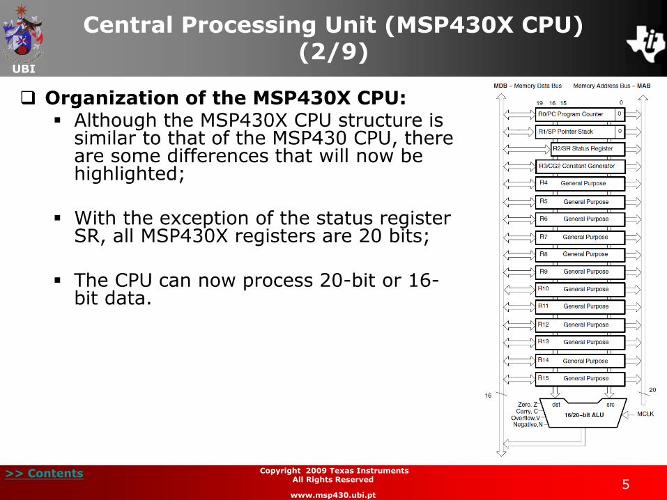
Organization of the MSP430X CPU: Although the MSP430X CPU structure is
similar to that of the MSP430 CPU, there are some differences that will now be highlighted;
With the exception of the status register SR, all MSP430X registers are 20 bits;
The CPU can now process 20-bit or 16-bit data.
Central Processing Unit (MSP430X CPU) (2/9)
UBI
>> Contents 6
Copyright 2009 Texas Instruments All Rights Reserved
www.msp430.ubi.pt
Central Processing Unit (MSP430X CPU) (3/9)
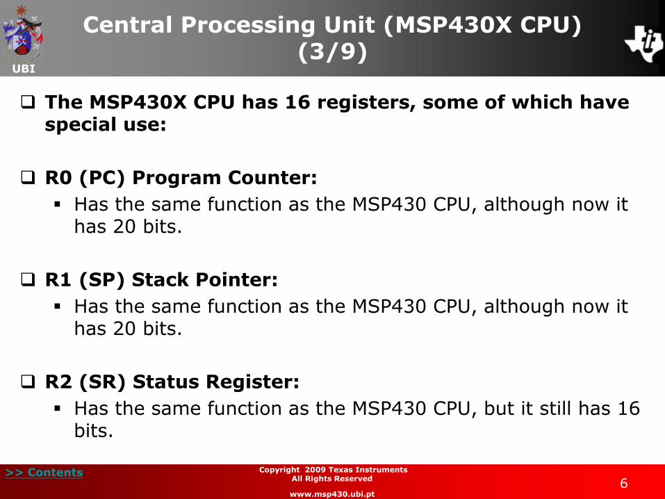
The MSP430X CPU has 16 registers, some of which have special use:
R0 (PC) Program Counter:
Has the same function as the MSP430 CPU, although now it has 20 bits.
R1 (SP) Stack Pointer:
Has the same function as the MSP430 CPU, although now it has 20 bits.
R2 (SR) Status Register:
Has the same function as the MSP430 CPU, but it still has 16 bits.
UBI
>> Contents 7
Copyright 2009 Texas Instruments All Rights Reserved
www.msp430.ubi.pt
Central Processing Unit (MSP430X CPU) (4/9)
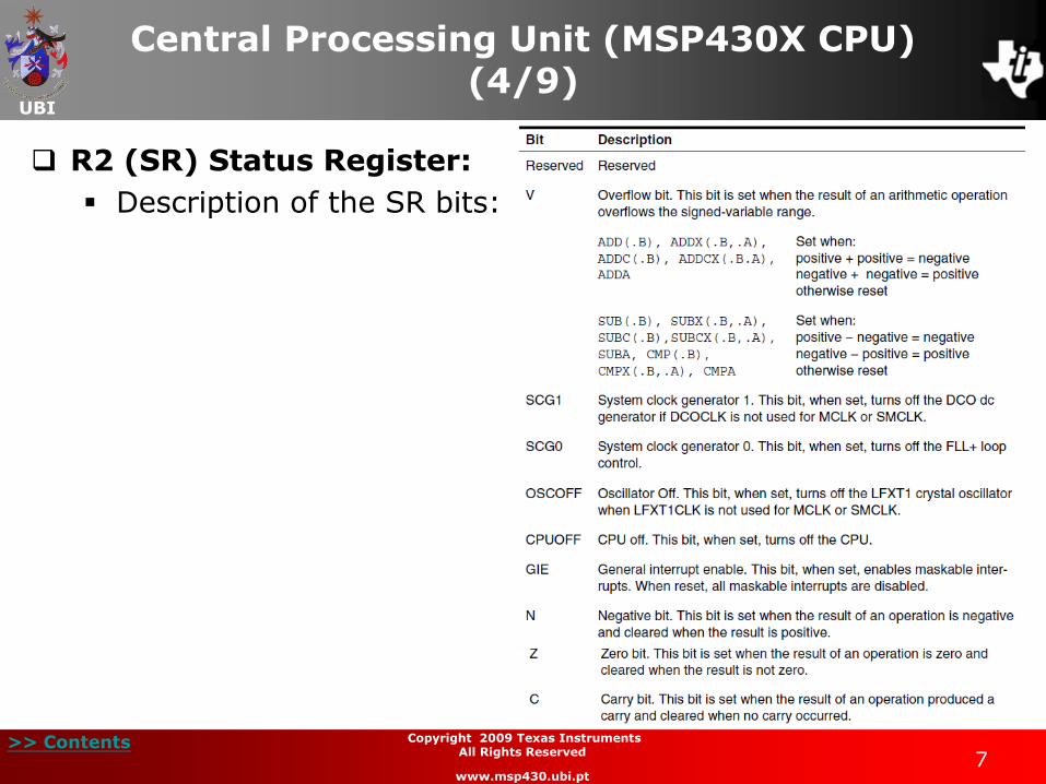
R2 (SR) Status Register:
Description of the SR bits:
UBI
>> Contents 8
Copyright 2009 Texas Instruments All Rights Reserved
www.msp430.ubi.pt
Central Processing Unit (MSP430X CPU) (5/9)
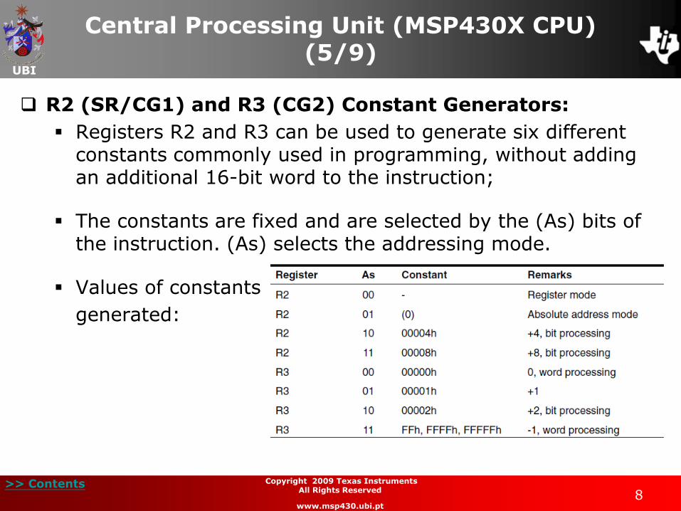
R2 (SR/CG1) and R3 (CG2) Constant Generators:
Registers R2 and R3 can be used to generate six different constants commonly used in programming, without adding an additional 16-bit word to the instruction;
The constants are fixed and are selected by the (As) bits of the instruction. (As) selects the addressing mode.
Values of constants
generated:

UBI
>> Contents 9
Copyright 2009 Texas Instruments All Rights Reserved
www.msp430.ubi.pt
Central Processing Unit (MSP430X CPU) (6/9)
R2 (SR/CG1) and R3 (CG2) Constant Generators:
Whenever the operand is one of the six constants, the registers are selected automatically;
Therefore, when used in constant mode, registers R2 and R3 cannot be used as source registers.
R4-R15 – General-purpose registers:
Have the same function as in the MSP430 CPU, although they now have 20 bits;
These registers can process 8-bit, 16-bit or 20-bit data;
If a byte is written to one of these registers it takes bits 7:0, the bits 19:8 are filled with zeroes. If a word is written to one of these registers it takes bits 15:0, the bits 19:16 are filled with zeroes.
UBI
>> Contents 10
Copyright 2009 Texas Instruments All Rights Reserved
www.msp430.ubi.pt
Central Processing Unit (MSP430X CPU) (7/9)
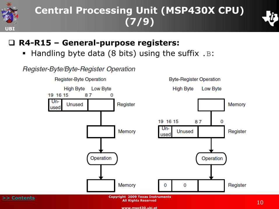
R4-R15 – General-purpose registers:
Handling byte data (8 bits) using the suffix .B:
UBI
>> Contents 11
Copyright 2009 Texas Instruments All Rights Reserved
www.msp430.ubi.pt
Central Processing Unit (MSP430X CPU) (8/9)
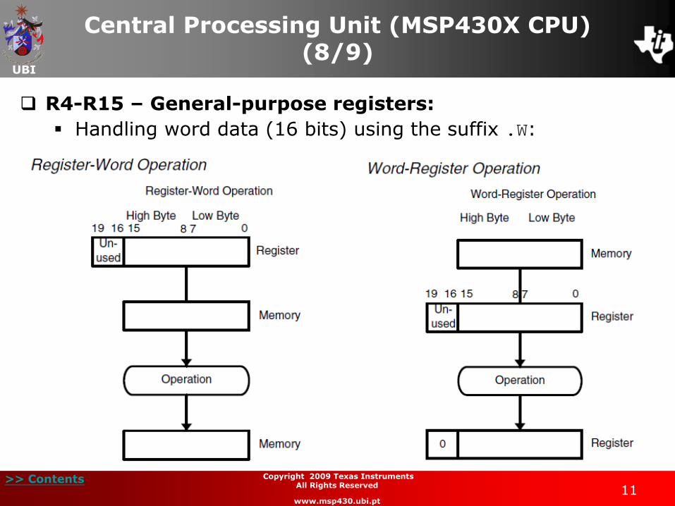
R4-R15 – General-purpose registers:
Handling word data (16 bits) using the suffix .W:
UBI
>> Contents 12
Copyright 2009 Texas Instruments All Rights Reserved
www.msp430.ubi.pt
Central Processing Unit (MSP430X CPU) (9/9)
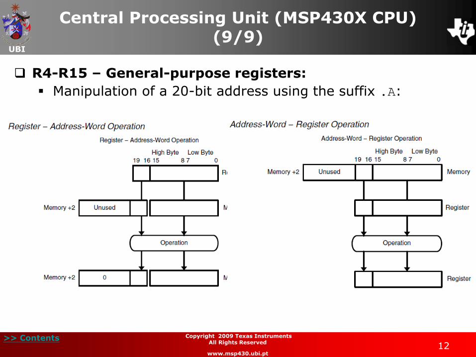
R4-R15 – General-purpose registers:
Manipulation of a 20-bit address using the suffix .A:
UBI
>> Contents 13
Copyright 2009 Texas Instruments All Rights Reserved
www.msp430.ubi.pt
Instruction format in the MSP430X CPU (1/2)
There are three possibilities to choose between the instructions of the MSP430 CPU and MSP430X CPU:
• Use only the MSP430 CPU instructions. The following rules must be followed, with the exception of the instructions CALLA/RETA, BRA:
– Put all the data in memory below 64 kB and access the data using 16-bit pointers;
– Place the routines at an address within the range PC 32 kB;
– No 20-bits data.
• Use only the MSP430X CPU instructions. This causes a reduction in the application execution speed and an increase in the memory space occupied by the program;
• Use an appropriate selection of the instruction types.
UBI
>> Contents 14
Copyright 2009 Texas Instruments All Rights Reserved
www.msp430.ubi.pt
Instruction format in the MSP430X CPU (2/2)
The MSP430X CPU supports all functions of the MSP430 CPU;
It also offers a set of instructions that provide full access to the 20-bit addressing space;
An additional op-code word is added to some of the instructions. Therefore all addresses, indexes and immediate numbers have 20 bits.
UBI
>> Contents 15
Copyright 2009 Texas Instruments All Rights Reserved
www.msp430.ubi.pt
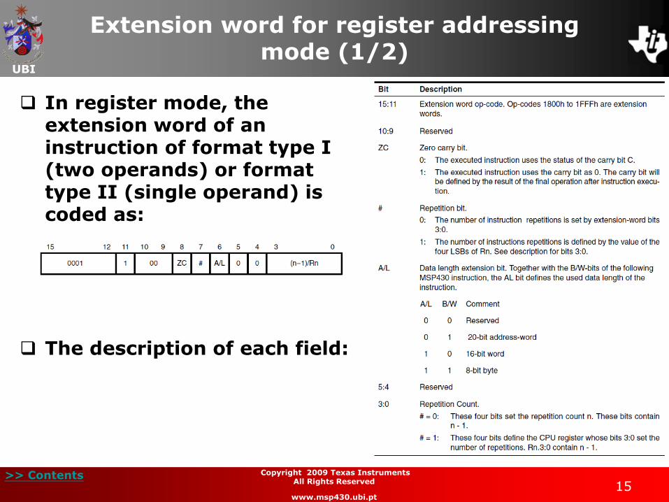
Extension word for register addressing mode (1/2)
In register mode, the extension word of an instruction of format type I (two operands) or format type II (single operand) is coded as:
The description of each field:
UBI
>> Contents 16
Copyright 2009 Texas Instruments All Rights Reserved
www.msp430.ubi.pt
Extension word for register addressing mode (2/2)
Unlike the MSP430, the MSP430X CPU supports the repeated execution of the same instruction, provided that the operands are of the register type;
The repetition is set by placing the repeat RPT instruction
before the instruction to be executed;
The assembler incorporates information in the extension word in the fields # (bit 7) and in the repetition counter (bits 3:0);
UBI
>> Contents 17
Copyright 2009 Texas Instruments All Rights Reserved
www.msp430.ubi.pt
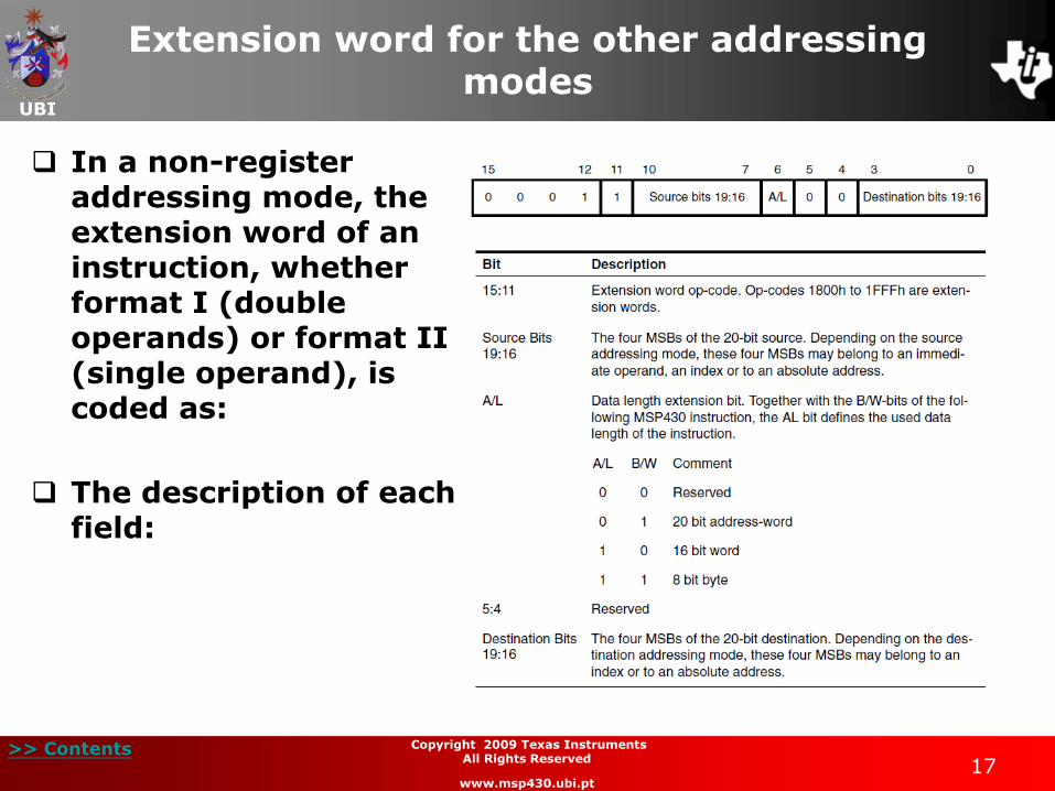
Extension word for the other addressing modes
In a non-register addressing mode, the extension word of an instruction, whether format I (double operands) or format II (single operand), is coded as:
The description of each field:
UBI
>> Contents 18
Copyright 2009 Texas Instruments All Rights Reserved
www.msp430.ubi.pt
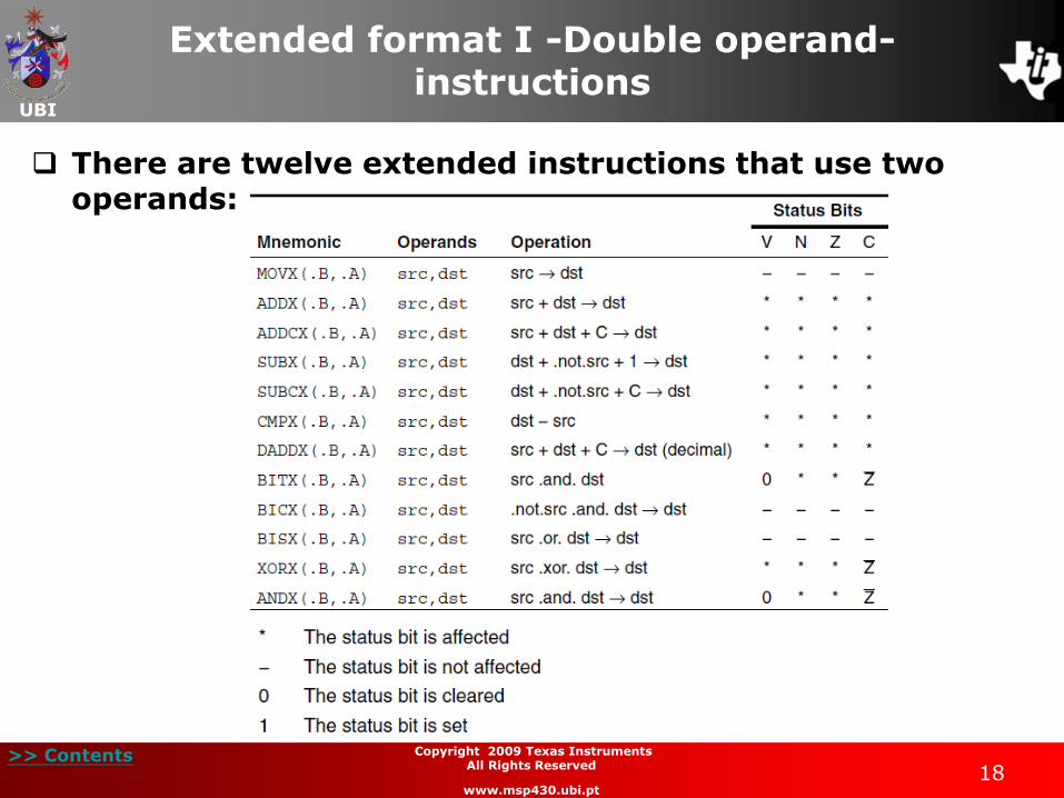
Extended format I -Double operand- instructions
There are twelve extended instructions that use two operands:
UBI
>> Contents 19
Copyright 2009 Texas Instruments All Rights Reserved
www.msp430.ubi.pt
Examples: Extended double operand instructions (1/7)
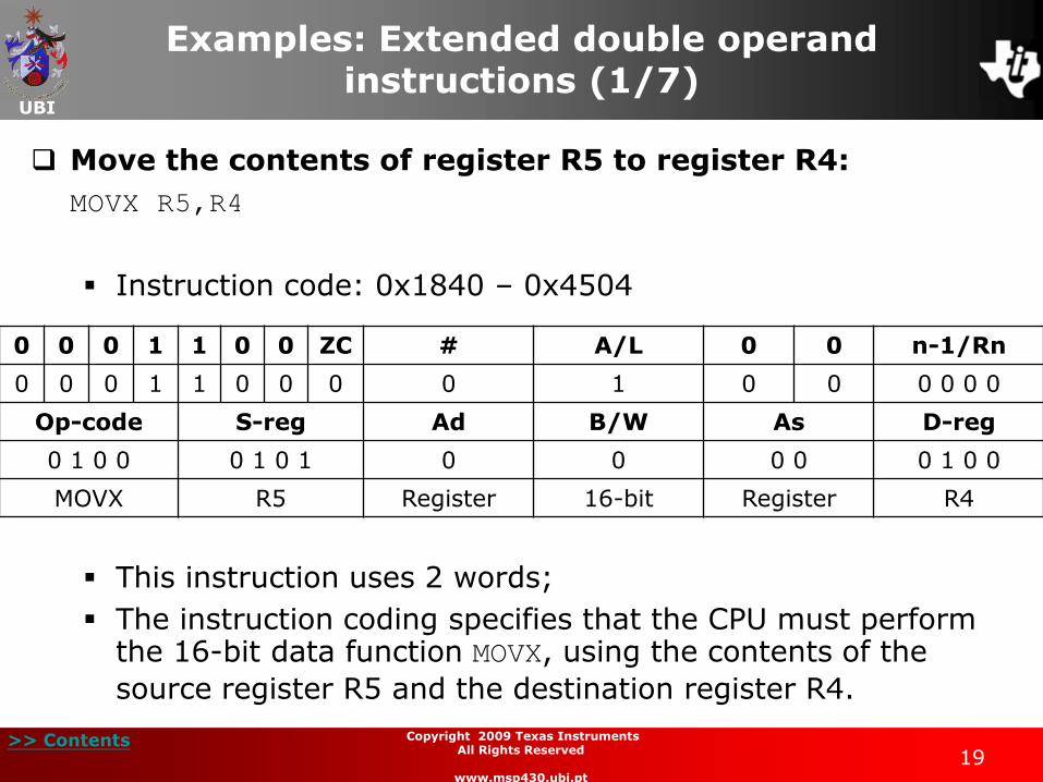
Move the contents of register R5 to register R4:
MOVX R5,R4
Instruction code: 0x1840 – 0x4504
This instruction uses 2 words;
The instruction coding specifies that the CPU must perform the 16-bit data function MOVX, using the contents of the
source register R5 and the destination register R4.
0 0 0 1 1 0 0 ZC # A/L 0 0 n-1/Rn
0 0 0 1 1 0 0 0 0 1 0 0 0 0 0 0
Op-code S-reg Ad B/W As D-reg
0 1 0 0 0 1 0 1 0 0 0 0 0 1 0 0
MOVX R5 Register 16-bit Register R4
UBI
>> Contents 20
Copyright 2009 Texas Instruments All Rights Reserved
www.msp430.ubi.pt
Examples: Extended double operand instructions (2/7)
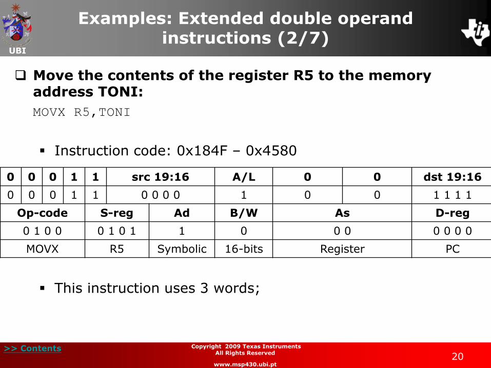
Move the contents of the register R5 to the memory address TONI:
MOVX R5,TONI
Instruction code: 0x184F – 0x4580
This instruction uses 3 words;
0 0 0 1 1 src 19:16 A/L 0 0 dst 19:16
0 0 0 1 1 0 0 0 0 1 0 0 1 1 1 1
Op-code S-reg Ad B/W As D-reg
0 1 0 0 0 1 0 1 1 0 0 0 0 0 0 0
MOVX R5 Symbolic 16-bits Register PC
UBI
>> Contents 21
Copyright 2009 Texas Instruments All Rights Reserved
www.msp430.ubi.pt
Examples: Extended double operand instructions (3/7)
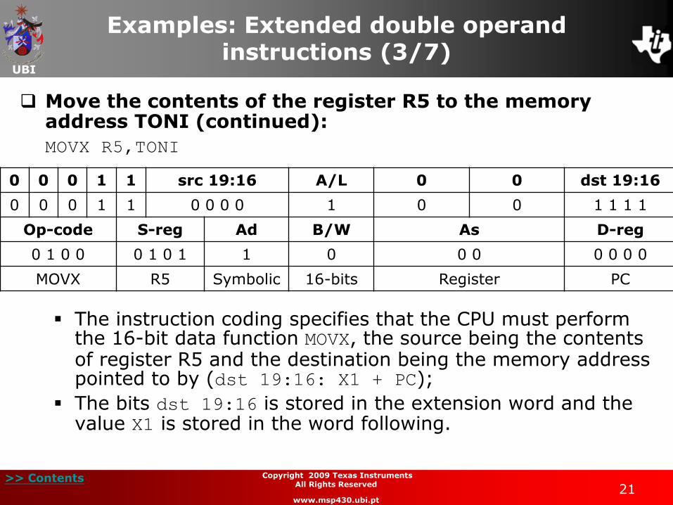
Move the contents of the register R5 to the memory address TONI (continued):
MOVX R5,TONI
The instruction coding specifies that the CPU must perform the 16-bit data function MOVX, the source being the contents of register R5 and the destination being the memory address pointed to by (dst 19:16: X1 + PC);
The bits dst 19:16 is stored in the extension word and the value X1 is stored in the word following.
0 0 0 1 1 src 19:16 A/L 0 0 dst 19:16
0 0 0 1 1 0 0 0 0 1 0 0 1 1 1 1
Op-code S-reg Ad B/W As D-reg
0 1 0 0 0 1 0 1 1 0 0 0 0 0 0 0
MOVX R5 Symbolic 16-bits Register PC
UBI
>> Contents 22
Copyright 2009 Texas Instruments All Rights Reserved
www.msp430.ubi.pt
Examples: Extended double operand instructions (4/7)
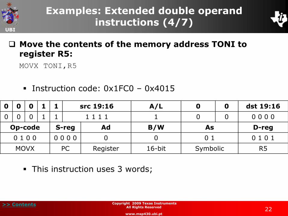
Move the contents of the memory address TONI to register R5:
MOVX TONI,R5
Instruction code: 0x1FC0 – 0x4015
This instruction uses 3 words;
0 0 0 1 1 src 19:16 A/L 0 0 dst 19:16
0 0 0 1 1 1 1 1 1 1 0 0 0 0 0 0
Op-code S-reg Ad B/W As D-reg
0 1 0 0 0 0 0 0 0 0 0 1 0 1 0 1
MOVX PC Register 16-bit Symbolic R5
UBI
>> Contents 23
Copyright 2009 Texas Instruments All Rights Reserved
www.msp430.ubi.pt
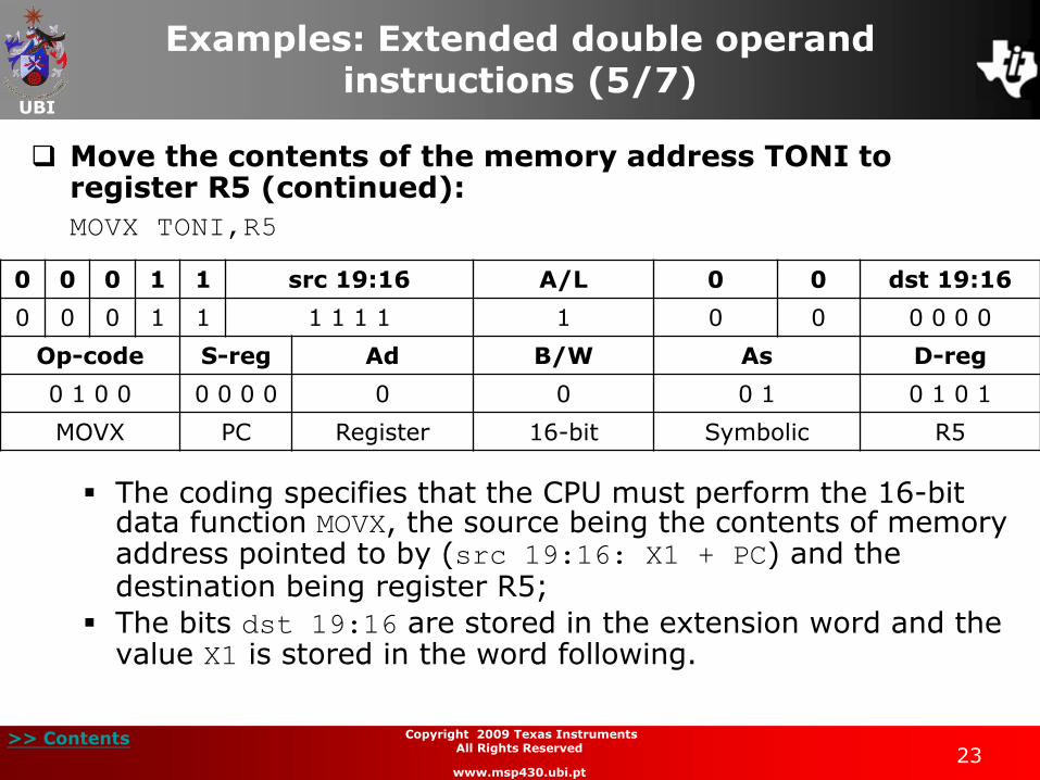
Examples: Extended double operand instructions (5/7)
Move the contents of the memory address TONI to register R5 (continued):
MOVX TONI,R5
The coding specifies that the CPU must perform the 16-bit data function MOVX, the source being the contents of memory address pointed to by (src 19:16: X1 + PC) and the destination being register R5;
The bits dst 19:16 are stored in the extension word and the value X1 is stored in the word following.
0 0 0 1 1 src 19:16 A/L 0 0 dst 19:16
0 0 0 1 1 1 1 1 1 1 0 0 0 0 0 0
Op-code S-reg Ad B/W As D-reg
0 1 0 0 0 0 0 0 0 0 0 1 0 1 0 1
MOVX PC Register 16-bit Symbolic R5

UBI
>> Contents 24
Copyright 2009 Texas Instruments All Rights Reserved
www.msp430.ubi.pt
Examples: Extended double operand instructions (6/7)
Move the contents of the memory address TONI to the memory address EDEN:
MOVX TONI,EDEN
Instruction code: 0x1FCF – 0x4090
This instruction uses 4 words;
0 0 0 1 1 src 19:16 A/L 0 0 dst 19:16
0 0 0 1 1 1 1 1 1 1 0 0 1 1 1 1
Op-code S-reg Ad B/W As D-reg
0 1 0 0 0 0 0 0 1 0 0 1 0 0 0 0
MOVX PC Symbolic 16-Bit Symbolic PC
UBI
>> Contents 25
Copyright 2009 Texas Instruments All Rights Reserved
www.msp430.ubi.pt
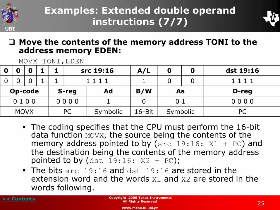
Examples: Extended double operand instructions (7/7)
Move the contents of the memory address TONI to the address memory EDEN:
MOVX TONI,EDEN
The coding specifies that the CPU must perform the 16-bit data function MOVX, the source being the contents of the memory address pointed to by (src 19:16: X1 + PC) and the destination being the contents of the memory address pointed to by (dst 19:16: X2 + PC);
The bits src 19:16 and dst 19:16 are stored in the extension word and the words X1 and X2 are stored in the words following.
0 0 0 1 1 src 19:16 A/L 0 0 dst 19:16
0 0 0 1 1 1 1 1 1 1 0 0 1 1 1 1
Op-code S-reg Ad B/W As D-reg
0 1 0 0 0 0 0 0 1 0 0 1 0 0 0 0
MOVX PC Symbolic 16-Bit Symbolic PC
UBI
>> Contents 26
Copyright 2009 Texas Instruments All Rights Reserved
www.msp430.ubi.pt
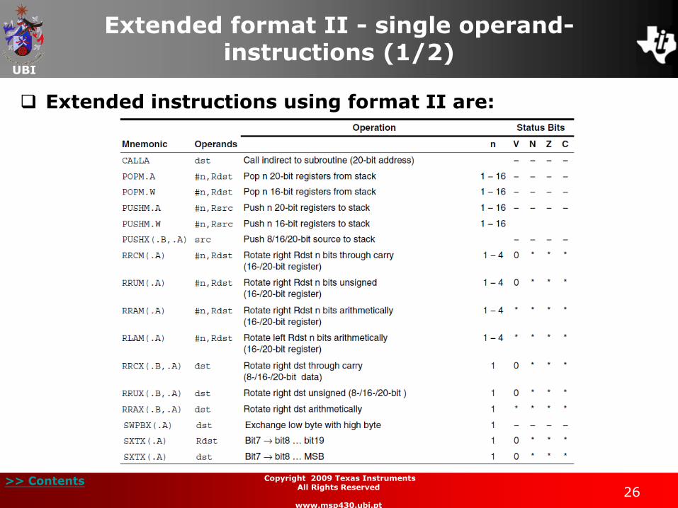
Extended format II - single operand- instructions (1/2)
Extended instructions using format II are:
UBI
>> Contents 27
Copyright 2009 Texas Instruments All Rights Reserved
www.msp430.ubi.pt
Extended format II - single operand- instructions (2/2)
The MSP430X CPU has some additional capabilities in addition to those of the MSP430 CPU:
The ability to push/pop several registers on/off the data stack using only a single instruction;
The ability to rotate the contents of a register several times during the execution of a single instruction.

UBI
>> Contents 28
Copyright 2009 Texas Instruments All Rights Reserved
www.msp430.ubi.pt
Examples: Extended single operand instructions (1/4)
Rotate right the 20-bit contents of register R5 with the carry flag:
RRCX.A R5
Instruction code: 0x1800 – 0x1045
This instruction uses 2 words;
The coding specifies that the CPU must perform the function RRCX using the 20-bit data contents of register R5.
0 0 0 1 1 0 0 ZC # A/L 0 0 n-1/Rn
0 0 0 1 1 0 0 0 0 0 0 0 0 0 0 0
Op-code B/W Ad D/S-reg
0 0 0 1 0 0 0 0 0 1 0 0 0 1 0 1
RRCX 20-bit Register R5
UBI
>> Contents 29
Copyright 2009 Texas Instruments All Rights Reserved
www.msp430.ubi.pt
Examples: Extended single operand instructions (2/4)
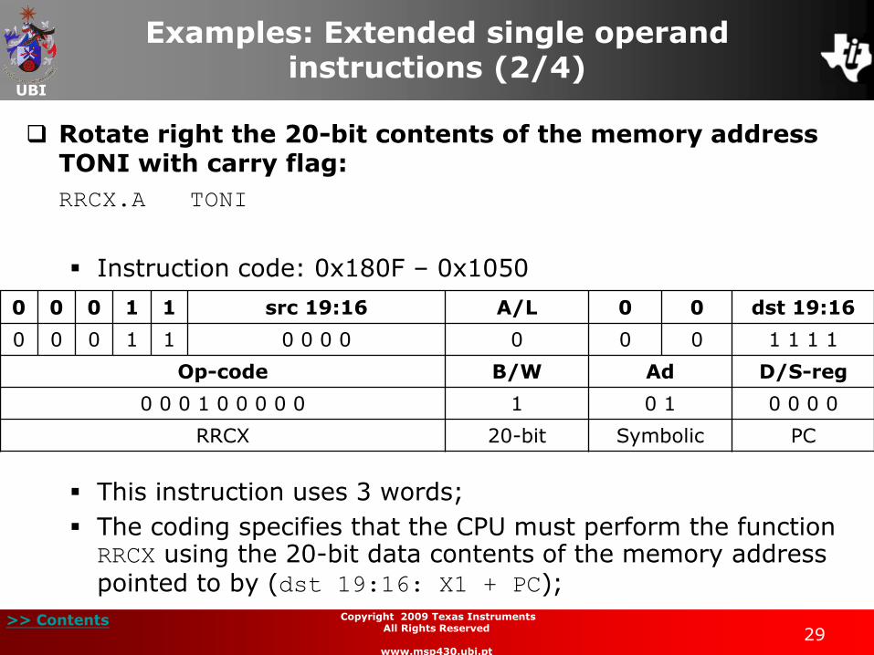
Rotate right the 20-bit contents of the memory address TONI with carry flag:
RRCX.A TONI
Instruction code: 0x180F – 0x1050
This instruction uses 3 words;
The coding specifies that the CPU must perform the function RRCX using the 20-bit data contents of the memory address pointed to by (dst 19:16: X1 + PC);
0 0 0 1 1 src 19:16 A/L 0 0 dst 19:16
0 0 0 1 1 0 0 0 0 0 0 0 1 1 1 1
Op-code B/W Ad D/S-reg
0 0 0 1 0 0 0 0 0 1 0 1 0 0 0 0
RRCX 20-bit Symbolic PC

UBI
>> Contents 30
Copyright 2009 Texas Instruments All Rights Reserved
www.msp430.ubi.pt
Examples: Extended single operand instructions (3/4)
Rotate right the 20-bit contents of the memory address TONI with carry flag (continued):
RRCX.A TONI
Instruction code: 0x180F – 0x1050
The bits dst 19:16 are stored in the extension word and the value X1 is stored in the word following;
0 0 0 1 1 src 19:16 A/L 0 0 dst 19:16
0 0 0 1 1 0 0 0 0 0 0 0 1 1 1 1
Op-code B/W Ad D/S-reg
0 0 0 1 0 0 0 0 0 1 0 1 0 0 0 0
RRCX 20-bit Symbolic PC
UBI
>> Contents 31
Copyright 2009 Texas Instruments All Rights Reserved
www.msp430.ubi.pt
Examples: Extended single operand instructions (4/4)
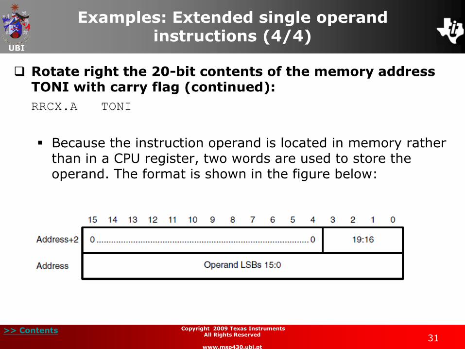
Rotate right the 20-bit contents of the memory address TONI with carry flag (continued):
RRCX.A TONI
Because the instruction operand is located in memory rather than in a CPU register, two words are used to store the operand. The format is shown in the figure below:
UBI
>> Contents 32
Copyright 2009 Texas Instruments All Rights Reserved
www.msp430.ubi.pt
Exceptions to the representation of the extended Format II instructions (1/7)
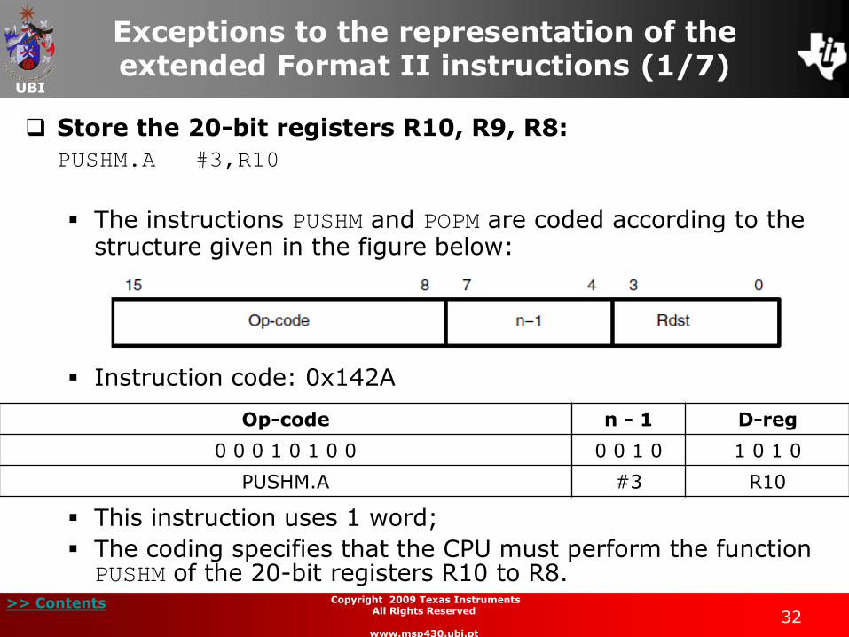
Store the 20-bit registers R10, R9, R8:
PUSHM.A #3,R10
The instructions PUSHM and POPM are coded according to the structure given in the figure below:
Instruction code: 0x142A
This instruction uses 1 word;
The coding specifies that the CPU must perform the function PUSHM of the 20-bit registers R10 to R8.
Op-code n - 1 D-reg
0 0 0 1 0 1 0 0 0 0 1 0 1 0 1 0
PUSHM.A #3 R10
UBI
>> Contents 33
Copyright 2009 Texas Instruments All Rights Reserved
www.msp430.ubi.pt
Exceptions to the representation of the extended Format II instructions (2/7)
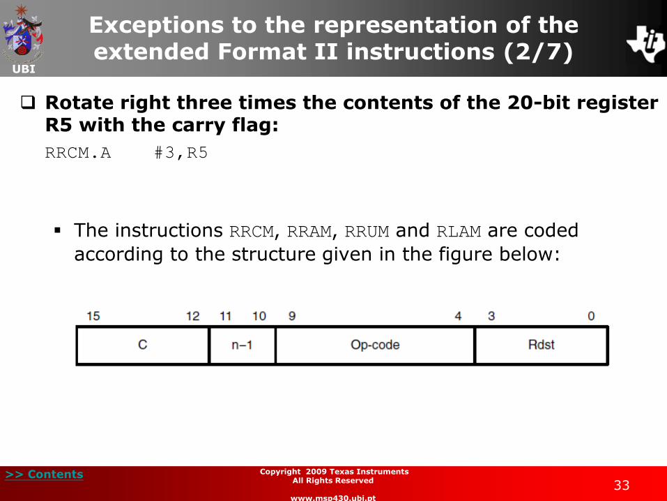
Rotate right three times the contents of the 20-bit register R5 with the carry flag:
RRCM.A #3,R5
The instructions RRCM, RRAM, RRUM and RLAM are coded
according to the structure given in the figure below:
UBI
>> Contents 34
Copyright 2009 Texas Instruments All Rights Reserved
www.msp430.ubi.pt
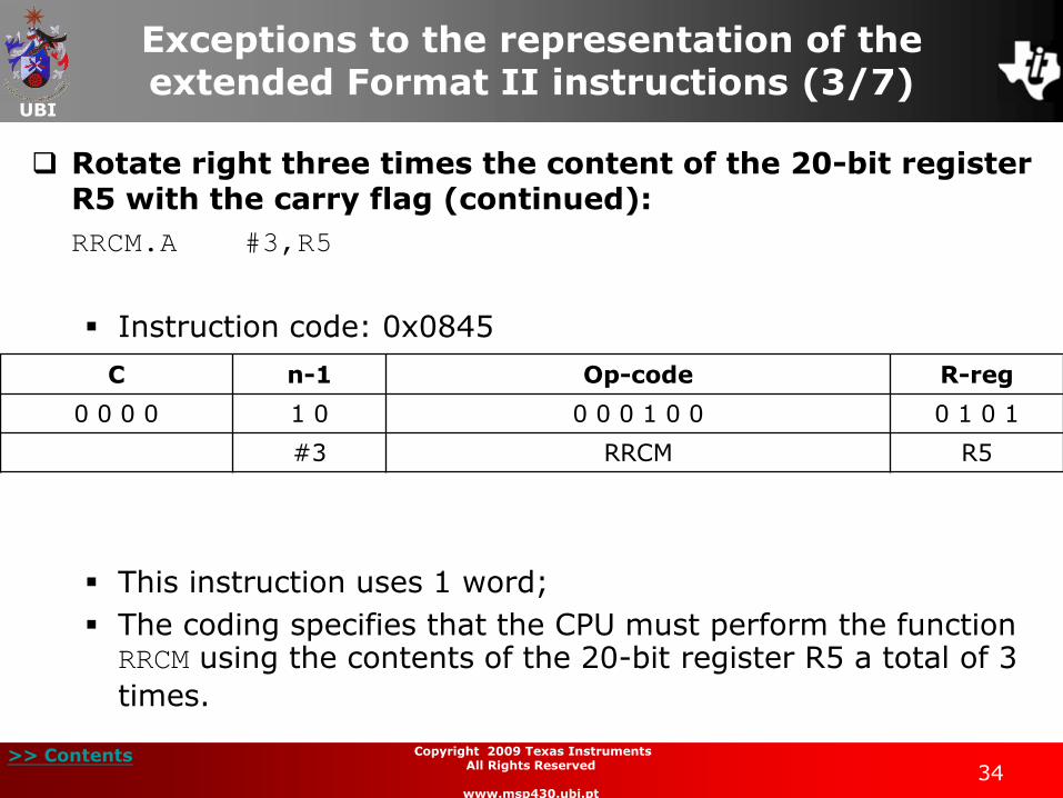
Exceptions to the representation of the extended Format II instructions (3/7)
Rotate right three times the content of the 20-bit register R5 with the carry flag (continued):
RRCM.A #3,R5
Instruction code: 0x0845
This instruction uses 1 word;
The coding specifies that the CPU must perform the function RRCM using the contents of the 20-bit register R5 a total of 3
times.
C n-1 Op-code R-reg
0 0 0 0 1 0 0 0 0 1 0 0 0 1 0 1
#3 RRCM R5
UBI
>> Contents 35
Copyright 2009 Texas Instruments All Rights Reserved
www.msp430.ubi.pt
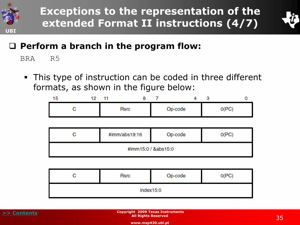
Exceptions to the representation of the extended Format II instructions (4/7)
Perform a branch in the program flow:
BRA R5
This type of instruction can be coded in three different formats, as shown in the figure below:

UBI
>> Contents 36
Copyright 2009 Texas Instruments All Rights Reserved
www.msp430.ubi.pt
Exceptions to the representation of the extended Format II instructions (5/7)
Perform a branch in the program flow (continued):
BRA R5
Instruction code: 0x05C0
This instruction uses 1 word;
The coding specifies that the PC must be loaded with the value in register R5.
C R-reg Op-code 0(PC)
0 0 0 0 0 1 0 1 1 1 0 0 0 0 0 0
R5 BRA PC
UBI
>> Contents 37
Copyright 2009 Texas Instruments All Rights Reserved
www.msp430.ubi.pt
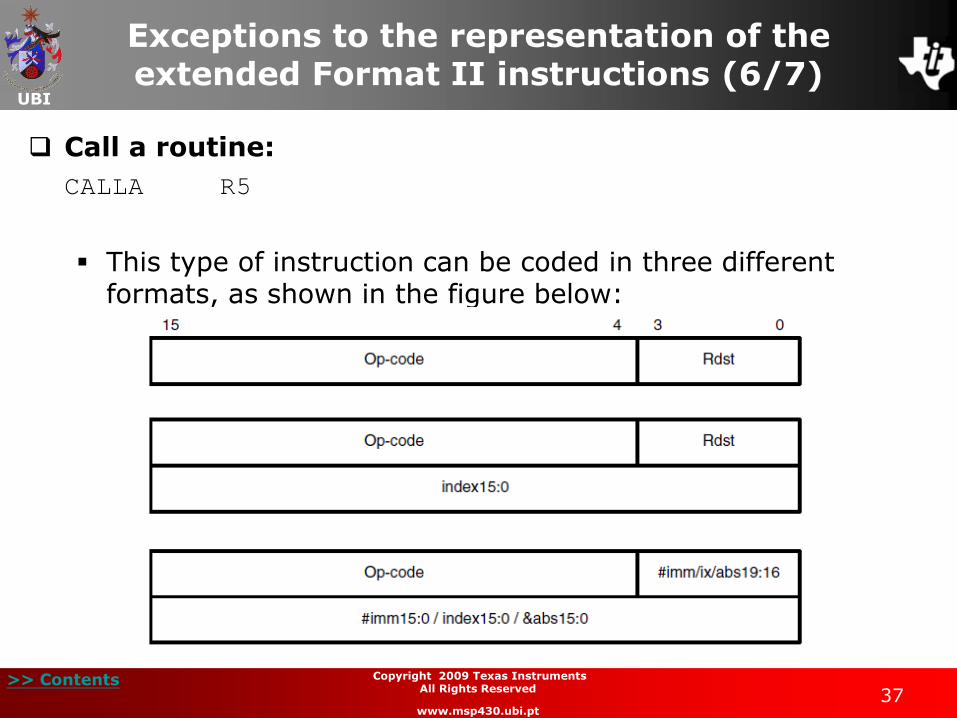
Exceptions to the representation of the extended Format II instructions (6/7)
Call a routine:
CALLA R5
This type of instruction can be coded in three different formats, as shown in the figure below:
UBI
>> Contents 38
Copyright 2009 Texas Instruments All Rights Reserved
www.msp430.ubi.pt
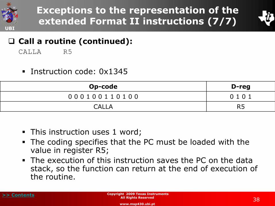
Exceptions to the representation of the extended Format II instructions (7/7)
Call a routine (continued):
CALLA R5
Instruction code: 0x1345
This instruction uses 1 word;
The coding specifies that the PC must be loaded with the value in register R5;
The execution of this instruction saves the PC on the data stack, so the function can return at the end of execution of the routine.
Op-code D-reg
0 0 0 1 0 0 1 1 0 1 0 0 0 1 0 1
CALLA R5
UBI
>> Contents 39
Copyright 2009 Texas Instruments All Rights Reserved
www.msp430.ubi.pt
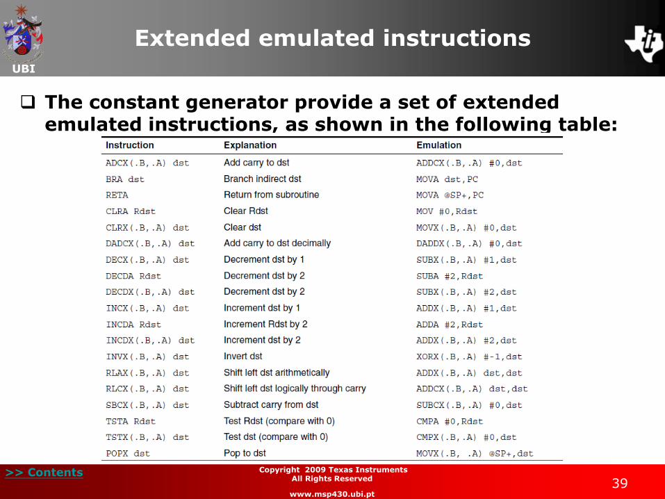
Extended emulated instructions
The constant generator provide a set of extended emulated instructions, as shown in the following table:
UBI
>> Contents 40
Copyright 2009 Texas Instruments All Rights Reserved
www.msp430.ubi.pt
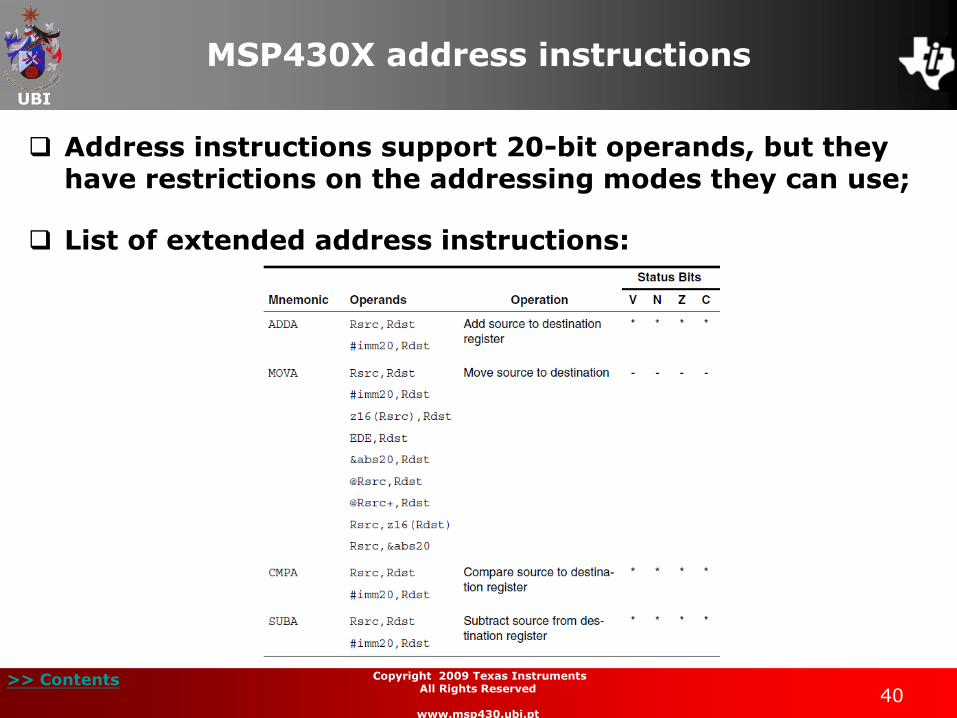
MSP430X address instructions
Address instructions support 20-bit operands, but they have restrictions on the addressing modes they can use;
List of extended address instructions:

UBI
>> Contents 41
Copyright 2009 Texas Instruments All Rights Reserved
www.msp430.ubi.pt
MSP430X CPU addressing modes
As with the MSP430 CPU, the MSP430X CPU supports seven addressing modes for the source operand and four addressing modes for the destination operand;
Both the MSP430 CPU and MSP430X CPU instructions can be used throughout the 1 MB address space;
In the following sections we will explore the different addressing modes available to the MSP430X CPU.
UBI
>> Contents 42
Copyright 2009 Texas Instruments All Rights Reserved
www.msp430.ubi.pt
Register mode (1/3)
This addressing mode is identical to that of the MSP430 CPU;
There are three different types of access to the registers:
8-bit access (Byte operation);
16-bit access (Word operation);
20-bit access (Address-word).
The instruction SXT is the only exception, as the sign of
the value is extended to the other bits of the register.

UBI
>> Contents 43
Copyright 2009 Texas Instruments All Rights Reserved
www.msp430.ubi.pt
Register mode (2/3)
Move the 20-bit contents of register R5 to register R4:
MOVX.A R5,R4
Instruction code: 0x1800 – 0x4544
The instruction uses 2 words.
The 20-bit contents (B/W = 1 and A/L = 0) of register R5 (S-reg = 0101) is transferred to register R4 (D-reg = 0100);
0 0 0 1 1 0 0 ZC # A/L 0 0 n-1/Rn
0 0 0 1 1 0 0 0 0 0 0 0 0 0 0 0
Op-code S-reg Ad B/W As D-reg
0 1 0 0 0 1 0 1 0 1 0 0 0 1 0 0
MOVX R5 Register 20-bit Register R4
UBI
>> Contents 44
Copyright 2009 Texas Instruments All Rights Reserved
www.msp430.ubi.pt
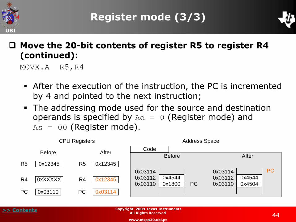
Register mode (3/3)
Move the 20-bit contents of register R5 to register R4 (continued):
MOVX.A R5,R4
After the execution of the instruction, the PC is incremented by 4 and pointed to the next instruction;
The addressing mode used for the source and destination operands is specified by Ad = 0 (Register mode) and As = 00 (Register mode).
CPU Registers
Before After
0x03110PC 0x03114PC
0xXXXXXR4 R4 0x12345
0x12345R5 0x12345R5
Address Space
0x4544
0x1800 PC0x031100x031120x03114
0x4544
0x4504
PC
0x031100x031120x03114
Before After
Code
UBI
>> Contents 45
Copyright 2009 Texas Instruments All Rights Reserved
www.msp430.ubi.pt
Indexed mode
Indexed mode can be used in three different situations:
Indexed mode in the memory address space below 64 kB;
Indexed mode in the memory address space above 64 kB;
Indexed mode using a MSP430X CPU instruction.
UBI
>> Contents 46
Copyright 2009 Texas Instruments All Rights Reserved
www.msp430.ubi.pt
Indexed mode: below 64 kB (1/4)
Indexed mode in the memory address space below 64 kB:
If the CPU register Rn points to a memory address located below 64 kB, the address resulting from the sum of the index and the register Rn has the value zero in bits 19:16.
This ensures that the address is always located in memory below 64 kB.
UBI
>> Contents 47
Copyright 2009 Texas Instruments All Rights Reserved
www.msp430.ubi.pt
Indexed mode: below 64 kB (2/4)
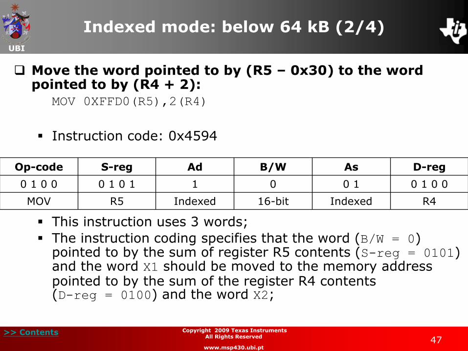
Move the word pointed to by (R5 – 0x30) to the word pointed to by (R4 + 2):
MOV 0XFFD0(R5),2(R4)
Instruction code: 0x4594
This instruction uses 3 words;
The instruction coding specifies that the word (B/W = 0) pointed to by the sum of register R5 contents (S-reg = 0101) and the word X1 should be moved to the memory address pointed to by the sum of the register R4 contents (D-reg = 0100) and the word X2;
Op-code S-reg Ad B/W As D-reg
0 1 0 0 0 1 0 1 1 0 0 1 0 1 0 0
MOV R5 Indexed 16-bit Indexed R4
UBI
>> Contents 48
Copyright 2009 Texas Instruments All Rights Reserved
www.msp430.ubi.pt
Indexed mode: below 64 kB (3/4)
Move the word pointed to by (R5 – 0x30) to the word pointed to by (R4 + 2) (continued):
MOV 0XFFD0(R5),2(R4)
The words X1 and X2 are located in the memory addresses
following the instruction;
The addressing mode used for the source and destination operands is specified by the bits Ad = 1 (Indexed mode) and As = 01 (Indexed mode), because D-reg = 0100 and S-reg = 0101 respectively;
In this example, bits 19:16 are set to zero when the operand addresses are calculated.

UBI
>> Contents 49
Copyright 2009 Texas Instruments All Rights Reserved
www.msp430.ubi.pt
Indexed mode: below 64 kB (4/4)
Move the word pointed to by (R5 – 0x30) to the word pointed to by (R4 + 2) (continued):
MOV 0XFFD0(R5),2(R4)
Data
CPU Registers
Before After
0x03110PC 0x03116PC
0x00200R4 R4 0x00200
0x00200R5 0x00200R5
Address Space
0x00200
0xFFFD00x001D0
0x1234 0x1234X1(R5)0x001D0 0x001D0 X1(R5)
0x00200
0x000020x00202 0xXXXX0x00202 0x12340x00202X2(R4) X2(R4)
0x0002
0xFFD0
0x4594 PC0x031100x031120x031140x03116
0x0002
0xFFD0
0x4594
PC
Before After
Code
X1
X2X1
X2
Destination Address
Source Address
(R4)(X2)
(R5)(X1)
0x031100x031120x031140x03116
UBI
>> Contents 50
Copyright 2009 Texas Instruments All Rights Reserved
www.msp430.ubi.pt
Indexed mode: above 64 kB (1/2)
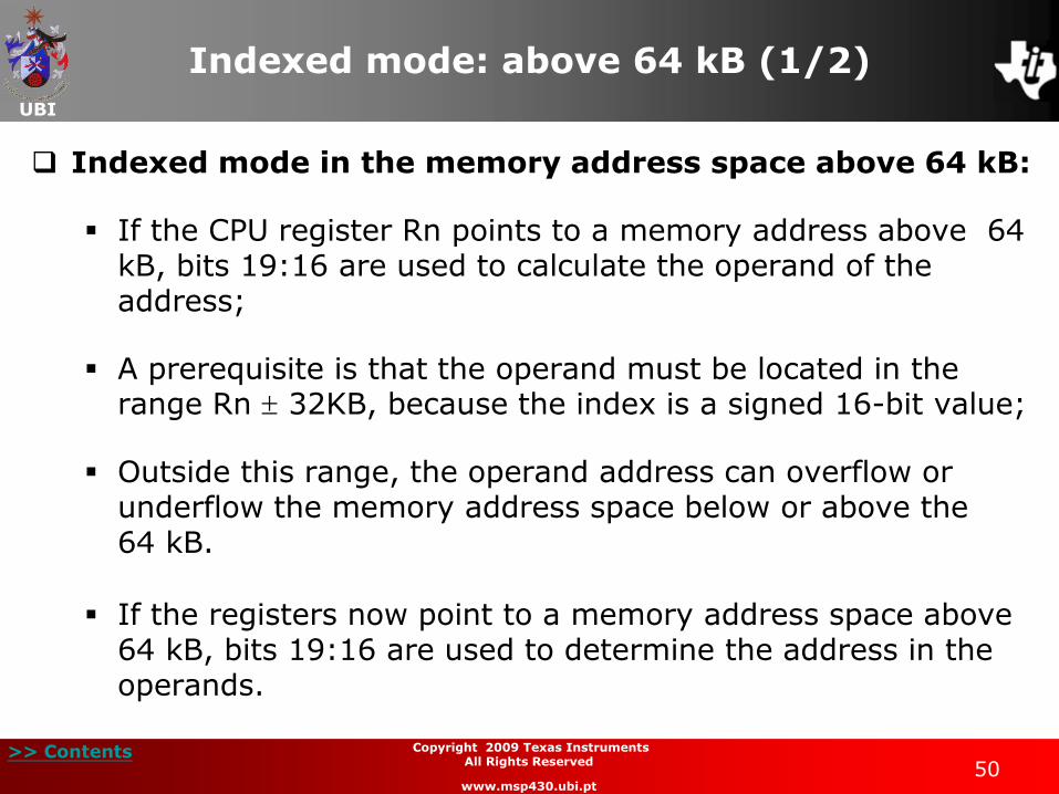
Indexed mode in the memory address space above 64 kB:
If the CPU register Rn points to a memory address above 64 kB, bits 19:16 are used to calculate the operand of the address;
A prerequisite is that the operand must be located in the range Rn 32KB, because the index is a signed 16-bit value;
Outside this range, the operand address can overflow or underflow the memory address space below or above the 64 kB.
If the registers now point to a memory address space above 64 kB, bits 19:16 are used to determine the address in the operands.

UBI
>> Contents 51
Copyright 2009 Texas Instruments All Rights Reserved
www.msp430.ubi.pt
Indexed mode: above 64 kB (2/2)
Indexed mode in the memory address space above 64 kB (continued):
Data
CPU Registers
Before After
0x03110PC 0x03116PC
0x00200R4 R4 0x00200
0x101D0R5 0x101D0R5
Address Space
0x101D0
0xFFFD00x101A0
0x1234 0x1234X1(R5)0x101A0 0x101A0 X1(R5)
0x00200
0x000020x00202 0xXXXX0x00202 0x12340x00202X2(R4) X2(R4)
0x0002
0xFFD0
0x4594 PC0x031100x031120x031140x03116
0x0002
0xFFD0
0x4594
PC
Before After
Code
X1
X2X1
X2
Destination Address
Source Address
(R4)(X2)
(R5)(X1)
0x031100x031120x031140x03116
UBI
>> Contents 52
Copyright 2009 Texas Instruments All Rights Reserved
www.msp430.ubi.pt
Indexed mode: MSP430X CPU (1/4)
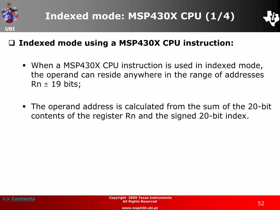
Indexed mode using a MSP430X CPU instruction:
When a MSP430X CPU instruction is used in indexed mode, the operand can reside anywhere in the range of addresses Rn 19 bits;
The operand address is calculated from the sum of the 20-bit contents of the register Rn and the signed 20-bit index.
UBI
>> Contents 53
Copyright 2009 Texas Instruments All Rights Reserved
www.msp430.ubi.pt
Indexed mode: MSP430X (2/4)
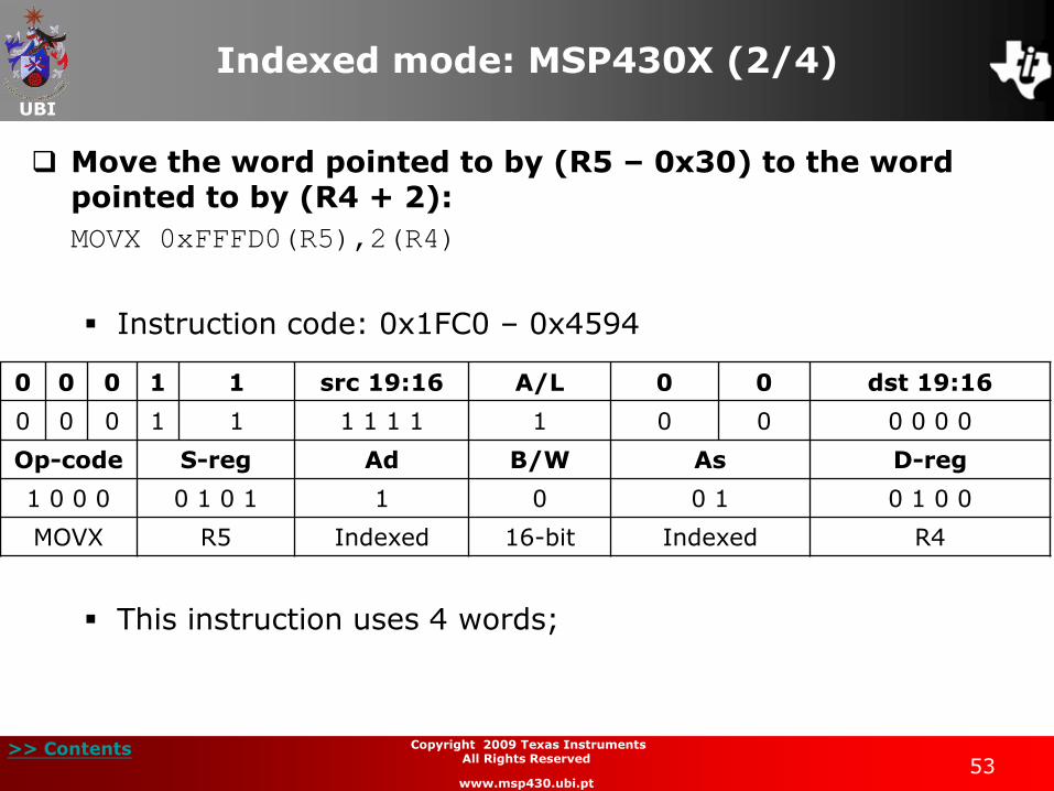
Move the word pointed to by (R5 – 0x30) to the word pointed to by (R4 + 2):
MOVX 0xFFFD0(R5),2(R4)
Instruction code: 0x1FC0 – 0x4594
This instruction uses 4 words;
0 0 0 1 1 src 19:16 A/L 0 0 dst 19:16
0 0 0 1 1 1 1 1 1 1 0 0 0 0 0 0
Op-code S-reg Ad B/W As D-reg
1 0 0 0 0 1 0 1 1 0 0 1 0 1 0 0
MOVX R5 Indexed 16-bit Indexed R4
UBI
>> Contents 54
Copyright 2009 Texas Instruments All Rights Reserved
www.msp430.ubi.pt
Indexed mode: MSP430X CPU (3/4)
Move the word pointed to by (R5 – 0x30) to the word pointed to by (R4 + 2) (continued):
MOVX 0xFFFD0(R5),2(R4)
The instruction coding specifies that the word (B/W = 0 and A/L = 1) pointed to by the sum of register R5 contents (S-reg = 0101) and the word X1 should be moved to the memory address pointed to by the sum of the register R4 contents (D-reg = 0100) and the word X2;
The four MSB indices are placed in the extension word of the instruction and the other 16 bits are placed in the words following the instruction;
The addressing mode used for the source and destination operands is specified by the bits Ad = 1 (Indexed mode) and As = 01 (Indexed mode), because D-reg = 0100 and S-reg = 0101 respectively.
UBI
>> Contents 55
Copyright 2009 Texas Instruments All Rights Reserved
www.msp430.ubi.pt
Indexed mode: MSP430X CPU (4/4)
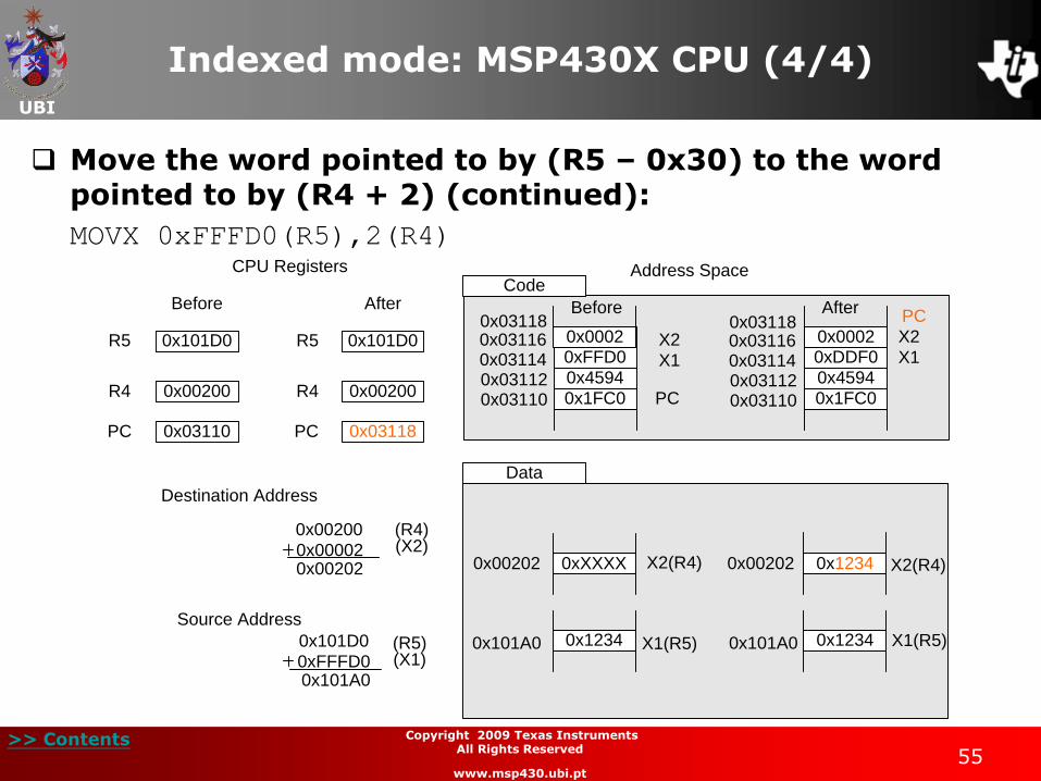
Move the word pointed to by (R5 – 0x30) to the word pointed to by (R4 + 2) (continued):
MOVX 0xFFFD0(R5),2(R4)
Data
CPU Registers
Before After
0x03110PC 0x03118PC
0x00200R4 R4 0x00200
0x101D0R5 0x101D0R5
Address Space
0x101D0
0xFFFD00x101A0
0x1234 0x1234X1(R5)0x101A0 0x101A0 X1(R5)
0x00200
0x000020x00202 0xXXXX0x00202 0x12340x00202X2(R4) X2(R4)
0xFFD0
0x4594
0x1FC0 PC
0xDDF0
0x4594
0x1FC0
PCBefore After
Code
X1
X2X1
X2
Destination Address
Source Address
(R4)(X2)
(R5)(X1)
0x0002 0x0002
0x031100x031120x031140x031160x03118
0x031100x031120x031140x031160x03118
UBI
>> Contents 56
Copyright 2009 Texas Instruments All Rights Reserved
www.msp430.ubi.pt
Symbolic mode
The symbolic addressing mode uses the register PC to determine the location of the operand based on an index;
Similar to the previous addressing mode, there are three different ways to use symbolic mode with the MSP30X CPU.
Symbolic mode in the memory address space below 64 kB;
Symbolic mode in the memory address space above 64 kB;
Symbolic mode using a MSP430X CPU instruction.
UBI
>> Contents 57
Copyright 2009 Texas Instruments All Rights Reserved
www.msp430.ubi.pt
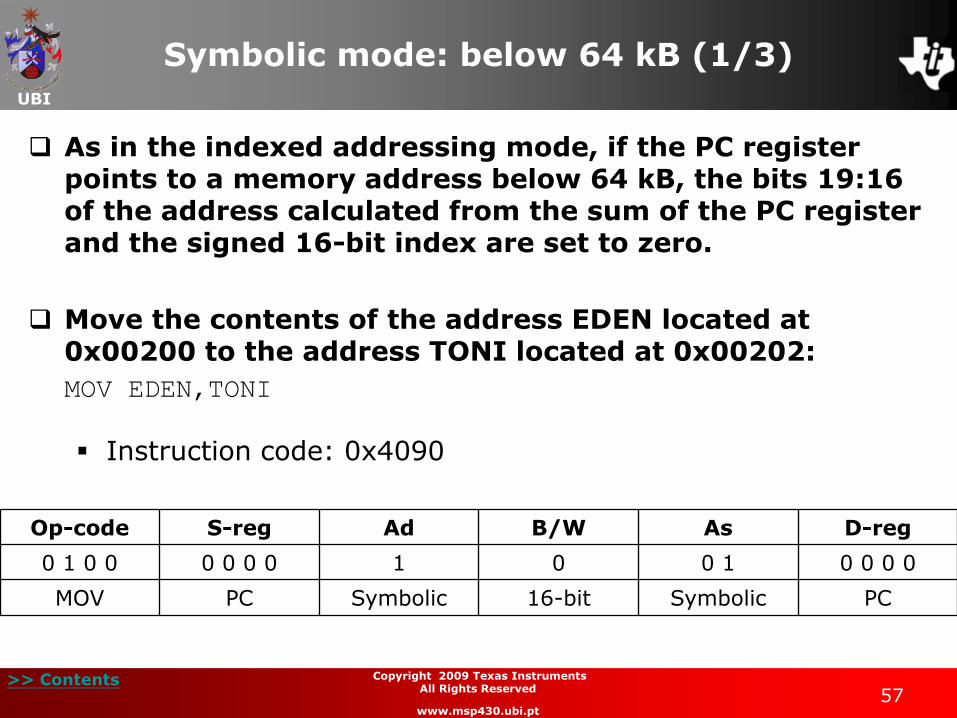
Symbolic mode: below 64 kB (1/3)
As in the indexed addressing mode, if the PC register points to a memory address below 64 kB, the bits 19:16 of the address calculated from the sum of the PC register and the signed 16-bit index are set to zero.
Move the contents of the address EDEN located at 0x00200 to the address TONI located at 0x00202:
MOV EDEN,TONI
Instruction code: 0x4090
Op-code S-reg Ad B/W As D-reg
0 1 0 0 0 0 0 0 1 0 0 1 0 0 0 0
MOV PC Symbolic 16-bit Symbolic PC
UBI
>> Contents 58
Copyright 2009 Texas Instruments All Rights Reserved
www.msp430.ubi.pt
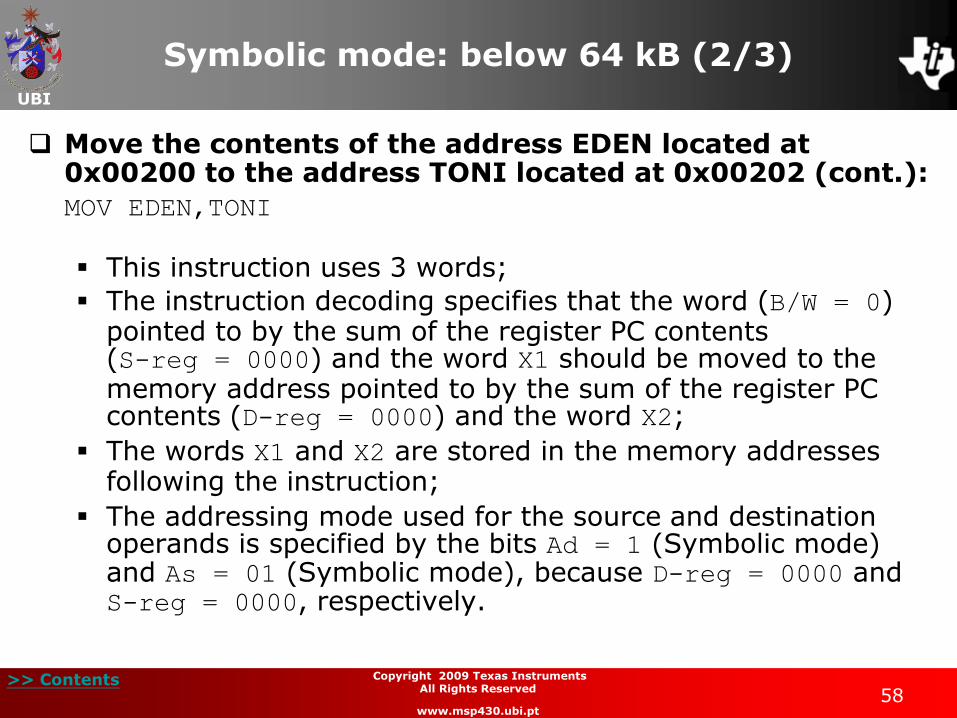
Symbolic mode: below 64 kB (2/3)
Move the contents of the address EDEN located at 0x00200 to the address TONI located at 0x00202 (cont.):
MOV EDEN,TONI
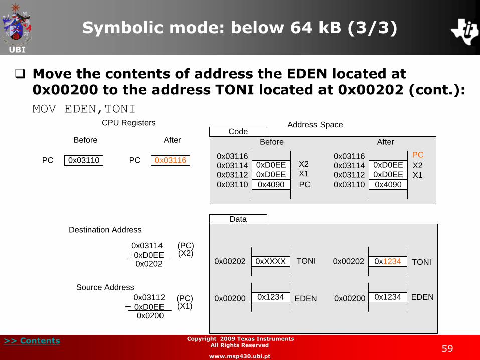
This instruction uses 3 words;
The instruction decoding specifies that the word (B/W = 0) pointed to by the sum of the register PC contents (S-reg = 0000) and the word X1 should be moved to the memory address pointed to by the sum of the register PC contents (D-reg = 0000) and the word X2;
The words X1 and X2 are stored in the memory addresses following the instruction;
The addressing mode used for the source and destination operands is specified by the bits Ad = 1 (Symbolic mode) and As = 01 (Symbolic mode), because D-reg = 0000 and S-reg = 0000, respectively.
UBI
>> Contents 59
Copyright 2009 Texas Instruments All Rights Reserved
www.msp430.ubi.pt
Symbolic mode: below 64 kB (3/3)
Move the contents of address the EDEN located at 0x00200 to the address TONI located at 0x00202 (cont.):
MOV EDEN,TONI
PC
Data
CPU Registers
Before After
0x03110 0x03116PC
Address Space
0x03112
0xD0EE0x0200
0x1234 0x1234EDEN0x00200 0x00200 EDEN
0x03114
0xD0EE0x0202 0xXXXX0x00202 0x12340x00202TONI TONI
0xD0EE
0xD0EE
0x4090 PC0x031100x031120x031140x03116
0xD0EE
0xD0EE
0x4090
PC
0x031100x031120x031140x03116
Before After
Code
X1
X2
X1
X2
Destination Address
Source Address
(PC)(X2)
(PC)(X1)

UBI
>> Contents 60
Copyright 2009 Texas Instruments All Rights Reserved
www.msp430.ubi.pt
Symbolic mode: above 64 kB (1/4)
If the PC register points to a memory address above 64 kB, bits 19:16 of the PC are used to calculate the operand address;
The operand must be located in the memory range PC 32 kB, because the index is a signed 16-bit value;
If outside this range, there may be an overflow or underflow in the address space corresponding to memory below 64 kB.
UBI
>> Contents 61
Copyright 2009 Texas Instruments All Rights Reserved
www.msp430.ubi.pt
Symbolic mode: above 64 kB (2/4)
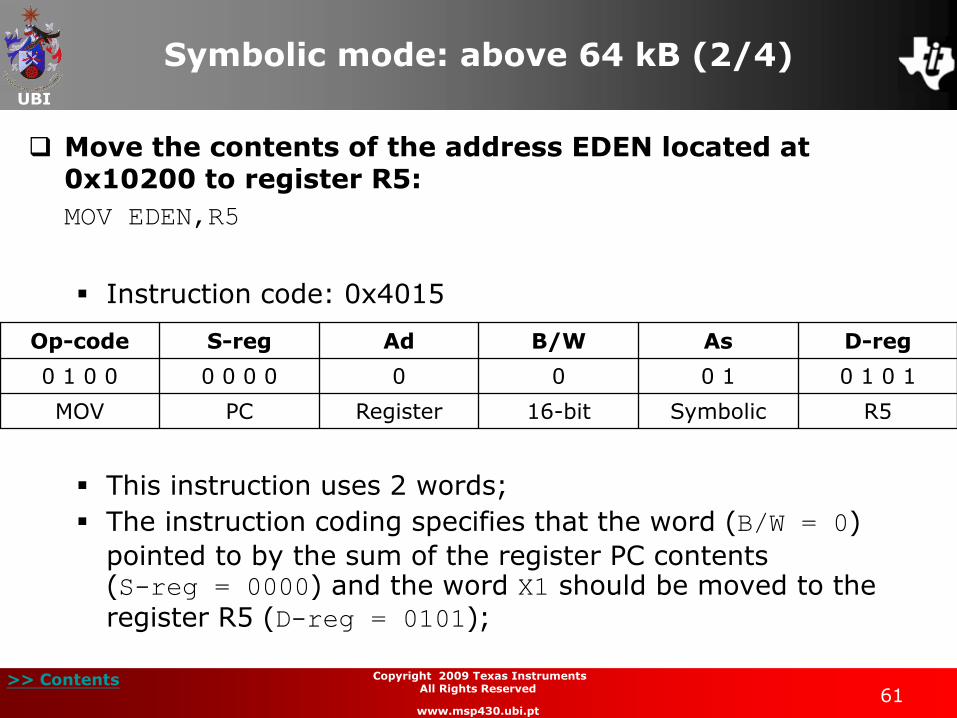
Move the contents of the address EDEN located at 0x10200 to register R5:
MOV EDEN,R5
Instruction code: 0x4015
This instruction uses 2 words;
The instruction coding specifies that the word (B/W = 0)
pointed to by the sum of the register PC contents (S-reg = 0000) and the word X1 should be moved to the register R5 (D-reg = 0101);
Op-code S-reg Ad B/W As D-reg
0 1 0 0 0 0 0 0 0 0 0 1 0 1 0 1
MOV PC Register 16-bit Symbolic R5
UBI
>> Contents 62
Copyright 2009 Texas Instruments All Rights Reserved
www.msp430.ubi.pt
Symbolic mode: above 64 kB (3/4)
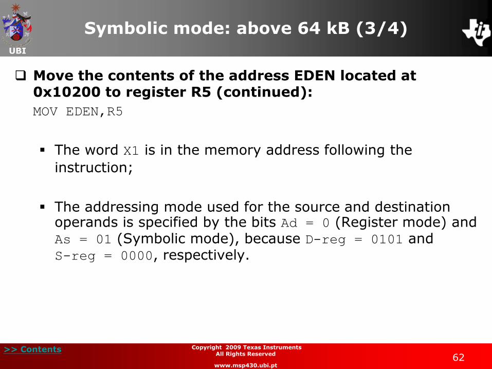
Move the contents of the address EDEN located at 0x10200 to register R5 (continued):
MOV EDEN,R5
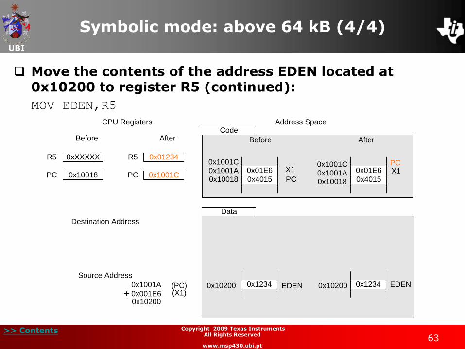
The word X1 is in the memory address following the
instruction;
The addressing mode used for the source and destination operands is specified by the bits Ad = 0 (Register mode) and As = 01 (Symbolic mode), because D-reg = 0101 and S-reg = 0000, respectively.
UBI
>> Contents 63
Copyright 2009 Texas Instruments All Rights Reserved
www.msp430.ubi.pt
Symbolic mode: above 64 kB (4/4)
Move the contents of the address EDEN located at 0x10200 to register R5 (continued):
MOV EDEN,R5
R5
Data
CPU Registers
Before After
0xXXXXX 0x01234R5
Address Space
0x1001A
0x001E60x10200
0x1234 0x1234EDEN0x10200 0x10200 EDEN
0x01E6
0x4015 PC0x100180x1001A0x1001C
0x01E6
0x4015
PC
Before After
Code
X1 X1
Destination Address
Source Address
(PC)(X1)
0x100180x1001A0x1001C
PC 0x10018 0x1001CPC
UBI
>> Contents 64
Copyright 2009 Texas Instruments All Rights Reserved
www.msp430.ubi.pt
Symbolic mode: MSP430X CPU (1/4)
When a MSP430X CPU instruction is used in symbolic mode, the operand can be located anywhere in the range of the addresses PC 19 bits;
The operand address is calculated from the sum of the 20-bit contents of the PC register and the signed 20-bit index.
UBI
>> Contents 65
Copyright 2009 Texas Instruments All Rights Reserved
www.msp430.ubi.pt
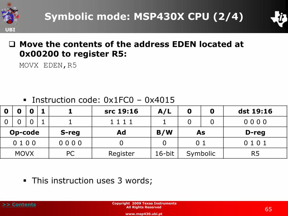
Symbolic mode: MSP430X CPU (2/4)
Move the contents of the address EDEN located at 0x00200 to register R5:
MOVX EDEN,R5
Instruction code: 0x1FC0 – 0x4015
This instruction uses 3 words;
0 0 0 1 1 src 19:16 A/L 0 0 dst 19:16
0 0 0 1 1 1 1 1 1 1 0 0 0 0 0 0
Op-code S-reg Ad B/W As D-reg
0 1 0 0 0 0 0 0 0 0 0 1 0 1 0 1
MOVX PC Register 16-bit Symbolic R5
UBI
>> Contents 66
Copyright 2009 Texas Instruments All Rights Reserved
www.msp430.ubi.pt
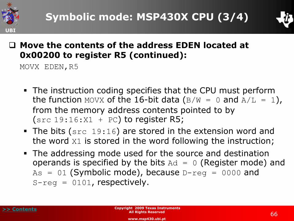
Symbolic mode: MSP430X CPU (3/4)
Move the contents of the address EDEN located at 0x00200 to register R5 (continued):
MOVX EDEN,R5
The instruction coding specifies that the CPU must perform the function MOVX of the 16-bit data (B/W = 0 and A/L = 1),
from the memory address contents pointed to by (src 19:16:X1 + PC) to register R5;
The bits (src 19:16) are stored in the extension word and the word X1 is stored in the word following the instruction;
The addressing mode used for the source and destination operands is specified by the bits Ad = 0 (Register mode) and As = 01 (Symbolic mode), because D-reg = 0000 and S-reg = 0101, respectively.
UBI
>> Contents 67
Copyright 2009 Texas Instruments All Rights Reserved
www.msp430.ubi.pt
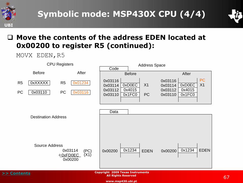
Symbolic mode: MSP430X CPU (4/4)
Move the contents of the address EDEN located at 0x00200 to register R5 (continued):
MOVX EDEN,R5
R5
Data
CPU Registers
Before After
0xXXXXX 0x01234R5
Address Space
0x03114
0xFD0EC0x00200
0x1234 0x1234EDEN0x00200 0x00200 EDEN
0xD0EC
0x4015
0x1FC0 PC0x031100x031120x031140x03116
0xD0EC
0x4015
0x1FC0
PC
0x031100x031120x031140x03116
Before After
Code
X1 X1
Destination Address
Source Address
(PC)(X1)
PC 0x03110 0x03116PC
UBI
>> Contents 68
Copyright 2009 Texas Instruments All Rights Reserved
www.msp430.ubi.pt
Absolute mode
Absolute mode uses the word contents following the instruction as the operand address;
There are two different ways to use absolute mode with the MSP30X CPU.
Absolute mode in the memory address space below 64 kB:
• In memory space below 64 kB, this instruction operates in the same way as the MSP430 CPU.
Absolute mode using a MSP430X CPU instruction.
UBI
>> Contents 69
Copyright 2009 Texas Instruments All Rights Reserved
www.msp430.ubi.pt
Absolute mode: MSP430X CPU (1/4)
If a MSP430X CPU instruction is used with an address in absolute mode, the 20-bit absolute address of the operand is used with an index of zero (generated by the constant generators) to point to the operand;
The four MSBs of the indices are placed in the extension word of the instruction and the other 16 bits are placed in the words following the instruction.

UBI
>> Contents 70
Copyright 2009 Texas Instruments All Rights Reserved
www.msp430.ubi.pt
Absolute mode: MSP430X CPU (2/4)
Move the contents of the address EDEN located at 0x00200 to the address TONI located at 0x00202:
MOVX &EDEN,&TONI
Instruction code: 0x1840 – 0x4292
This instruction uses 4 words;
0 0 0 1 1 src 19:16 A/L 0 0 dst 19:16
0 0 0 1 1 0 0 0 0 1 0 0 0 0 0 0
Op-code S-reg Ad B/W As D-reg
0 1 0 0 0 0 1 0 1 0 0 1 0 0 1 0
MOVX SR/CG1 Absolute 16-bit Absolute SR/CG1
UBI
>> Contents 71
Copyright 2009 Texas Instruments All Rights Reserved
www.msp430.ubi.pt
Absolute mode MSP430X CPU (3/4)
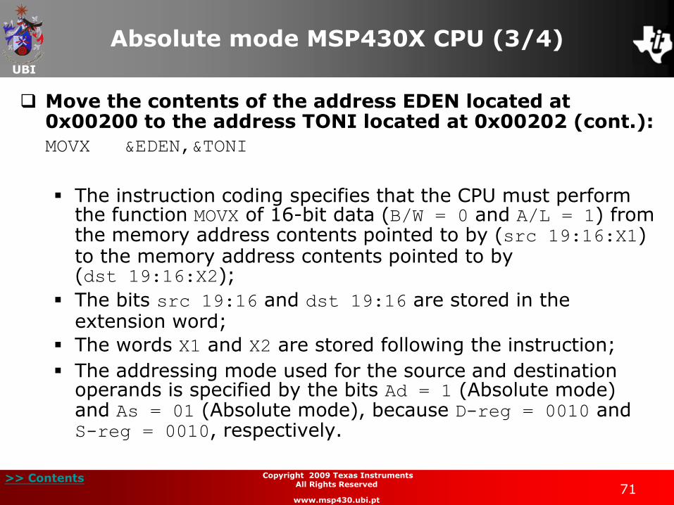
Move the contents of the address EDEN located at 0x00200 to the address TONI located at 0x00202 (cont.):
MOVX &EDEN,&TONI
The instruction coding specifies that the CPU must perform the function MOVX of 16-bit data (B/W = 0 and A/L = 1) from the memory address contents pointed to by (src 19:16:X1) to the memory address contents pointed to by (dst 19:16:X2);
The bits src 19:16 and dst 19:16 are stored in the extension word;
The words X1 and X2 are stored following the instruction;
The addressing mode used for the source and destination operands is specified by the bits Ad = 1 (Absolute mode) and As = 01 (Absolute mode), because D-reg = 0010 and S-reg = 0010, respectively.

UBI
>> Contents 72
Copyright 2009 Texas Instruments All Rights Reserved
www.msp430.ubi.pt
Absolute mode: MSP430X CPU (4/4)
Move the contents of the address EDEN located at 0x00200 to the address TONI located at 0x00202 (cont.):
MOVX &EDEN,&TONI
Data
CPU Registers
Before After
0x03110PC 0x03118PC
Address Space
0x1234 0x1234EDEN0x00200 0x00200 EDEN
0xXXXX0x00202 0x12340x00202TONI TONI
0x0200
0x4292
0x1840 PC
PCBefore After
Code
X1
X2X1
X2
Destination Address
Source Address
0x0202
0x031100x031120x031140x031160x03118
0x031100x031120x031140x031160x03118
0x0200
0x4292
0x1840
0x0202

UBI
>> Contents 73
Copyright 2009 Texas Instruments All Rights Reserved
www.msp430.ubi.pt
Indirect register mode (1/3)
Indirect addressing mode uses the contents of register Rn to point to the 20-bit operand;
It can only be used to point to the source operand.
Move the operand pointed to by the contents of register R5 to the memory address TONI located at 0x00202:
MOVX @R5,&TONI
Instruction code: 0x1840 – 0x45A2
0 0 0 1 1 src 19:16 A/L 0 0 dst 19:16
0 0 0 1 1 0 0 0 0 1 0 0 0 0 0 0
Op-code S-reg Ad B/W As D-reg
0 1 0 0 0 1 0 1 1 0 1 0 0 0 1 0
MOVX R5 Absolute 16-bit Indirect SR/CG1
UBI
>> Contents 74
Copyright 2009 Texas Instruments All Rights Reserved
www.msp430.ubi.pt
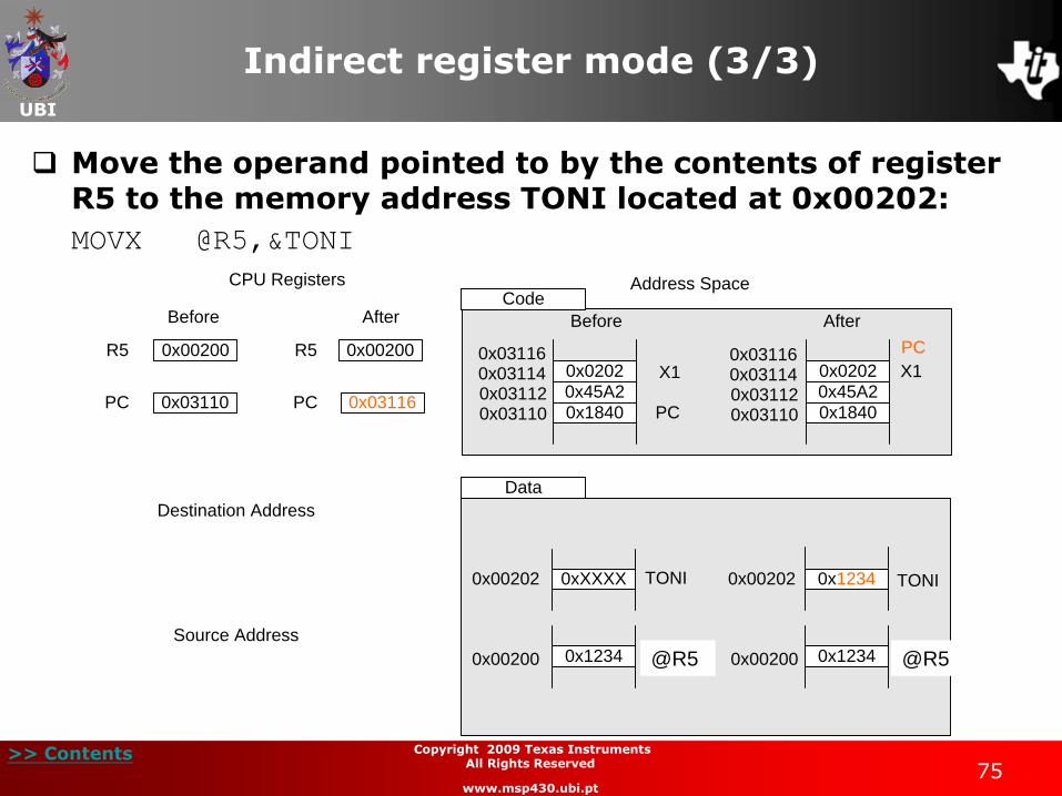
Indirect register mode (2/3)
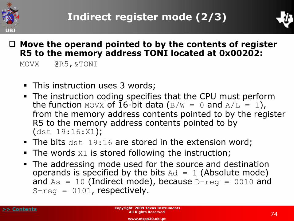
Move the operand pointed to by the contents of register R5 to the memory address TONI located at 0x00202:
MOVX @R5,&TONI
This instruction uses 3 words;
The instruction coding specifies that the CPU must perform the function MOVX of 16-bit data (B/W = 0 and A/L = 1), from the memory address contents pointed to by the register R5 to the memory address contents pointed to by (dst 19:16:X1);
The bits dst 19:16 are stored in the extension word;
The words X1 is stored following the instruction;
The addressing mode used for the source and destination operands is specified by the bits Ad = 1 (Absolute mode) and As = 10 (Indirect mode), because D-reg = 0010 and S-reg = 0101, respectively.
UBI
>> Contents 75
Copyright 2009 Texas Instruments All Rights Reserved
www.msp430.ubi.pt
Indirect register mode (3/3)
Move the operand pointed to by the contents of register R5 to the memory address TONI located at 0x00202:
MOVX @R5,&TONI
Data
CPU Registers
Before After
0x00200R5 0x00200R5
Address Space
0x1234 0x1234EDEN0x00200 0x00200 EDEN
0xXXXX0x00202 0x12340x00202TONI TONI
0x0202
0x45A2
0x1840 PC
PC
Before After
Code
X1 X1
Destination Address
Source Address
0x031100x031120x031140x03116
0x031100x031120x031140x03116
0x0202
0x45A2
0x18400x03110PC 0x03116PC
@R5 @R5
UBI
>> Contents 76
Copyright 2009 Texas Instruments All Rights Reserved
www.msp430.ubi.pt
Indirect auto-increment mode (1/4)
This addressing mode uses the contents of register Rn to point to the 20-bit source operand;
The register Rn is automatically incremented by 1 for a byte operand, by 2 for a word operand and by 4 for an address operand.
UBI
>> Contents 77
Copyright 2009 Texas Instruments All Rights Reserved
www.msp430.ubi.pt
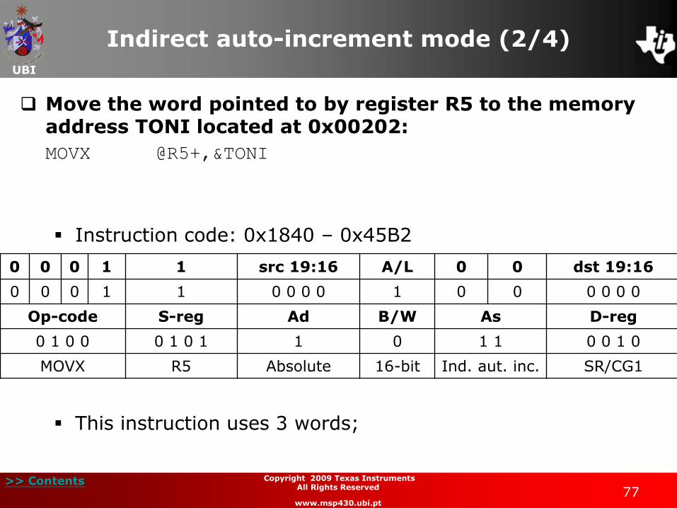
Indirect auto-increment mode (2/4)
Move the word pointed to by register R5 to the memory address TONI located at 0x00202:
MOVX @R5+,&TONI
Instruction code: 0x1840 – 0x45B2
This instruction uses 3 words;
0 0 0 1 1 src 19:16 A/L 0 0 dst 19:16
0 0 0 1 1 0 0 0 0 1 0 0 0 0 0 0
Op-code S-reg Ad B/W As D-reg
0 1 0 0 0 1 0 1 1 0 1 1 0 0 1 0
MOVX R5 Absolute 16-bit Ind. aut. inc. SR/CG1
UBI
>> Contents 78
Copyright 2009 Texas Instruments All Rights Reserved
www.msp430.ubi.pt
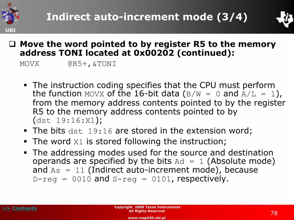
Indirect auto-increment mode (3/4)
Move the word pointed to by register R5 to the memory address TONI located at 0x00202 (continued):
MOVX @R5+,&TONI
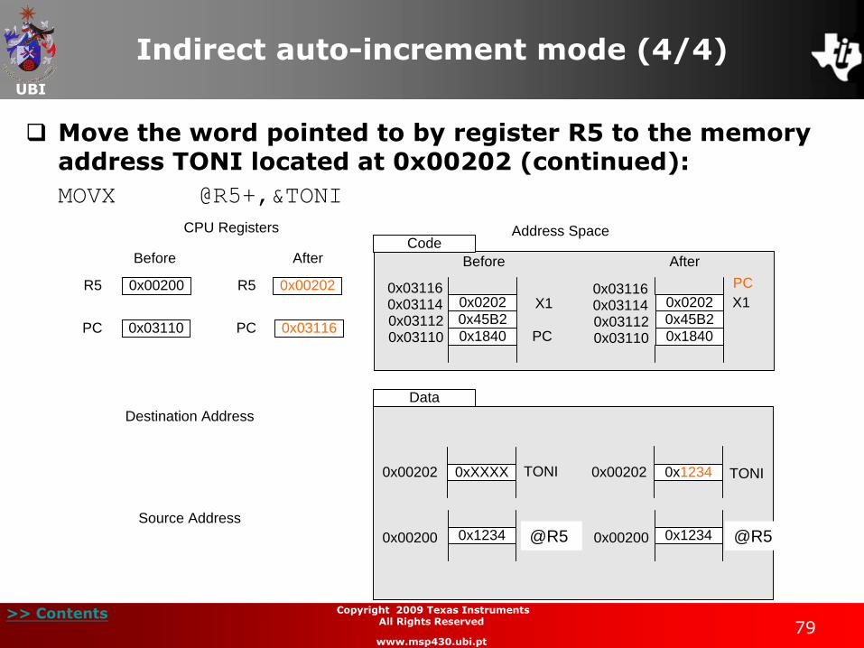
The instruction coding specifies that the CPU must perform the function MOVX of the 16-bit data (B/W = 0 and A/L = 1), from the memory address contents pointed to by the register R5 to the memory address contents pointed to by (dst 19:16:X1);
The bits dst 19:16 are stored in the extension word;
The word X1 is stored following the instruction;
The addressing modes used for the source and destination operands are specified by the bits Ad = 1 (Absolute mode) and As = 11 (Indirect auto-increment mode), because D-reg = 0010 and S-reg = 0101, respectively.
UBI
>> Contents 79
Copyright 2009 Texas Instruments All Rights Reserved
www.msp430.ubi.pt
Indirect auto-increment mode (4/4)
Move the word pointed to by register R5 to the memory address TONI located at 0x00202 (continued):
MOVX @R5+,&TONI
Data
CPU Registers
Before After
0x00200R5 0x00202R5
Address Space
0x1234 0x1234EDEN0x00200 0x00200 EDEN
0xXXXX0x00202 0x12340x00202TONI TONI
0x0202
0x45B2
0x1840 PC
PC
Before After
Code
X1 X1
Destination Address
Source Address
0x031100x031120x031140x03116
0x031100x031120x031140x03116
0x0202
0x45B2
0x18400x03110PC 0x03116PC
@R5 @R5
UBI
>> Contents 80
Copyright 2009 Texas Instruments All Rights Reserved
www.msp430.ubi.pt
Immediate mode
The immediate addressing mode allows constants to be placed after the instruction and use them as source operands;
There are two ways to use immediate mode:
A 8-bit or 16-bit constant with a MSP430 CPU instruction:
• The operation in this situation is similar to that of the MSP430 CPU.
A 20-bit constant with a MSP430X CPU instruction:
• If a MSP430X CPU instruction is used in immediate addressing mode, the constant has a 20-bit value;
• The bits 19:16 are stored in the extension word and the remaining bits are stored following the instruction.
UBI
>> Contents 81
Copyright 2009 Texas Instruments All Rights Reserved
www.msp430.ubi.pt
Immediate mode: MSP430X CPU (1/3)
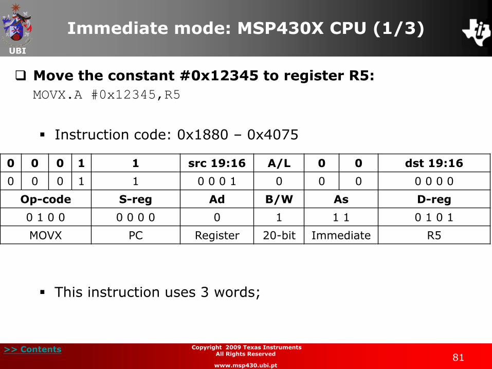
Move the constant #0x12345 to register R5:
MOVX.A #0x12345,R5
Instruction code: 0x1880 – 0x4075
This instruction uses 3 words;
0 0 0 1 1 src 19:16 A/L 0 0 dst 19:16
0 0 0 1 1 0 0 0 1 0 0 0 0 0 0 0
Op-code S-reg Ad B/W As D-reg
0 1 0 0 0 0 0 0 0 1 1 1 0 1 0 1
MOVX PC Register 20-bit Immediate R5
UBI
>> Contents 82
Copyright 2009 Texas Instruments All Rights Reserved
www.msp430.ubi.pt
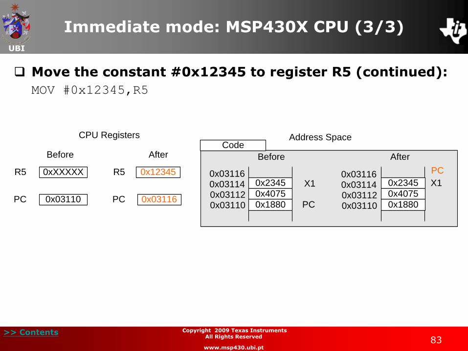
Immediate mode: MSP430X CPU (2/3)
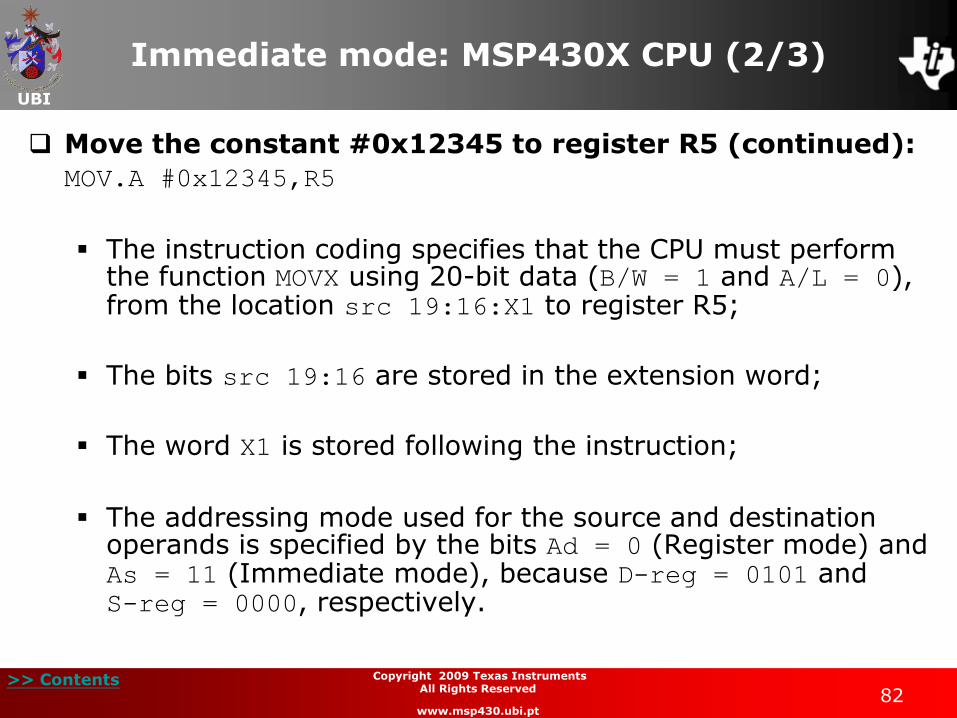
Move the constant #0x12345 to register R5 (continued):
MOV.A #0x12345,R5
The instruction coding specifies that the CPU must perform the function MOVX using 20-bit data (B/W = 1 and A/L = 0), from the location src 19:16:X1 to register R5;
The bits src 19:16 are stored in the extension word;
The word X1 is stored following the instruction;
The addressing mode used for the source and destination operands is specified by the bits Ad = 0 (Register mode) and As = 11 (Immediate mode), because D-reg = 0101 and S-reg = 0000, respectively.
UBI
>> Contents 83
Copyright 2009 Texas Instruments All Rights Reserved
www.msp430.ubi.pt
Immediate mode: MSP430X CPU (3/3)
Move the constant #0x12345 to register R5 (continued):
MOV #0x12345,R5
CPU Registers
Before After
0xXXXXXR5 0x12345R5
Address Space
0x2345
0x4075
0x1880 PC
PC
Before After
Code
X1 X1
0x031100x031120x031140x03116
0x031100x031120x031140x03116
0x2345
0x4075
0x18800x03110PC 0x03116PC
UBI
>> Contents 84
Copyright 2009 Texas Instruments All Rights Reserved
www.msp430.ubi.pt
Arithmetic and logic operations (1/9)
Special operations with MSP430X CPU - Repetition of an instruction:
An MP430X CPU instruction, provided that it is used in Register addressing mode, can be repeated a preset number of times, up to a maximum of 15 times;
It uses the instruction:
RPT #n ; repeat n times
RPT Rn ; repeat Rn.3:0 times
UBI
>> Contents 85
Copyright 2009 Texas Instruments All Rights Reserved
www.msp430.ubi.pt
Arithmetic and logic operations (2/9)
Special operations with MSP430X CPU - Repetition of an instruction (continued):
In the following example, the instructions sequence starts by loading the value 0x05AD into register R5;
The CPU is informed that it must repeat the arithmetic shift left instruction 3 times;
The resulting value in register R5 is the original value multiplied by 8.
MOV #0x05AD,R5
RPT #3
RLAX R5
UBI
>> Contents 86
Copyright 2009 Texas Instruments All Rights Reserved
www.msp430.ubi.pt
Arithmetic and logic operations (3/9)
Special operations with MSP430X CPU - Arithmetic successive shifts and carry flag (C) shifts:
The MSP430X CPU has an instruction set that allows a number of arithmetic shifts or shifts with carry to be carried out;
Up to a maximum of 4 shifts can be performed on a 16-bit or 20-bit value;
To perform #n shifts right of a register with the carry flag, the following instruction is used:
RRCM #n,Rdst or RRCM.W #n,Rdst
RRCM.A #n,Rdst
UBI
>> Contents 87
Copyright 2009 Texas Instruments All Rights Reserved
www.msp430.ubi.pt
Arithmetic and logic operations (4/9)
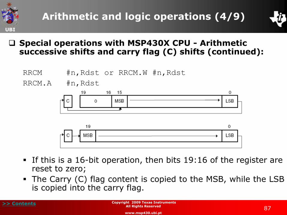
Special operations with MSP430X CPU - Arithmetic successive shifts and carry flag (C) shifts (continued):
RRCM #n,Rdst or RRCM.W #n,Rdst
RRCM.A #n,Rdst
If this is a 16-bit operation, then bits 19:16 of the register are reset to zero;
The Carry (C) flag content is copied to the MSB, while the LSB is copied into the carry flag.
UBI
>> Contents 88
Copyright 2009 Texas Instruments All Rights Reserved
www.msp430.ubi.pt
Arithmetic and logic operations (5/9)
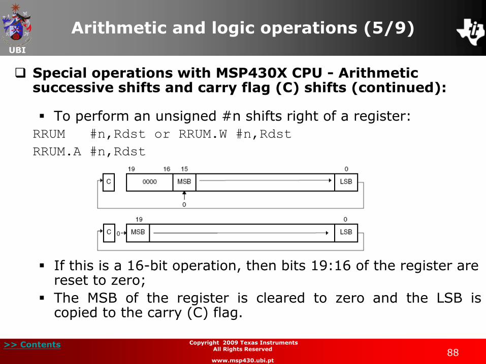
Special operations with MSP430X CPU - Arithmetic successive shifts and carry flag (C) shifts (continued):
To perform an unsigned #n shifts right of a register:
RRUM #n,Rdst or RRUM.W #n,Rdst
RRUM.A #n,Rdst
If this is a 16-bit operation, then bits 19:16 of the register are reset to zero;
The MSB of the register is cleared to zero and the LSB is copied to the carry (C) flag.

UBI
>> Contents 89
Copyright 2009 Texas Instruments All Rights Reserved
www.msp430.ubi.pt
Arithmetic and logic operations (6/9)
Special operations with MSP430X CPU - Arithmetic successive shifts and carry flag (C) shifts (continued):
To perform a #n arithmetic shift right of a register:
RRAM #n,Rdst or RRAM.W #n,Rdst
RRAM.A #n,Rdst
If this is a 16-bit operation, then bits 19:16 of the register are cleared to zero;
The operation allows the division of the register contents by 2, 4, 8 or 16, depending on the parameter #n;
During the arithmetic shift right of the register contents, the MSB is maintained, while the LSB is copied to the carry flag.
UBI
>> Contents 90
Copyright 2009 Texas Instruments All Rights Reserved
www.msp430.ubi.pt
Arithmetic and logic operations (7/9)
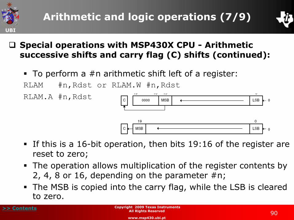
Special operations with MSP430X CPU - Arithmetic successive shifts and carry flag (C) shifts (continued):
To perform a #n arithmetic shift left of a register:
RLAM #n,Rdst or RLAM.W #n,Rdst
RLAM.A #n,Rdst
If this is a 16-bit operation, then bits 19:16 of the register are reset to zero;
The operation allows multiplication of the register contents by 2, 4, 8 or 16, depending on the parameter #n;
The MSB is copied into the carry flag, while the LSB is cleared to zero.
UBI
>> Contents 91
Copyright 2009 Texas Instruments All Rights Reserved
www.msp430.ubi.pt
Arithmetic and logic operations (8/9)
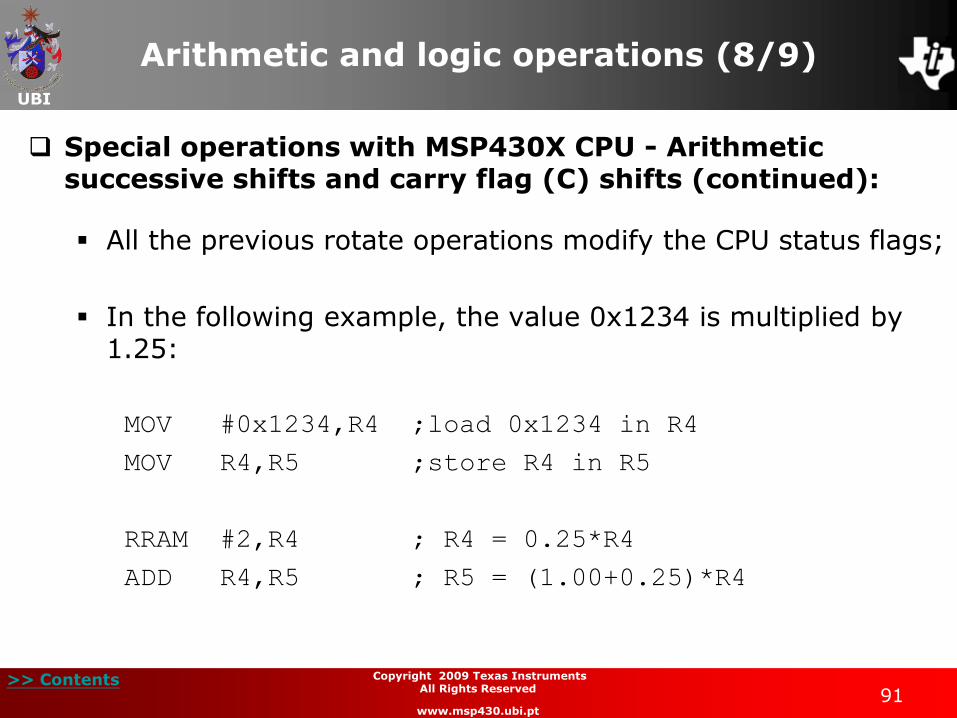
Special operations with MSP430X CPU - Arithmetic successive shifts and carry flag (C) shifts (continued):
All the previous rotate operations modify the CPU status flags;
In the following example, the value 0x1234 is multiplied by 1.25:
MOV #0x1234,R4 ;load 0x1234 in R4
MOV R4,R5 ;store R4 in R5
RRAM #2,R4 ; R4 = 0.25*R4
ADD R4,R5 ; R5 = (1.00+0.25)*R4
UBI
>> Contents 92
Copyright 2009 Texas Instruments All Rights Reserved
www.msp430.ubi.pt
Arithmetic and logic operations (9/9)
Special operations with MSP430X CPU - 20-bit addressing instructions:
The addressing instructions can use the 20-bit addresses. There is the limitation that with the exception of the instruction MOVA, only Register and Immediate addressing
modes can be used;
A 20-bit address can be manipulated using the following operations: addition (ADDA), subtraction (SUBA), double-increment (INCDA) and double-decrement (DECDA);
The contents of a register can be cleared by the instruction (CLRA);
A 20-bit operand can be moved using the instruction (MOVA);

UBI
>> Contents 93
Copyright 2009 Texas Instruments All Rights Reserved
www.msp430.ubi.pt
Stack pointer management (1/6)
MSP430X CPU stack pointer:
Stack access functions:
In addition to 8-bit or 16-bit values, the MSP430X CPU provides instructions with the ability to handle 20-bit data in memory;
This usually requires two instruction words to carry out a stack operation;
To place a 20-bit value on the stack, use the instruction:
PUSHX.A source

UBI
>> Contents 94
Copyright 2009 Texas Instruments All Rights Reserved
www.msp430.ubi.pt
Stack pointer management (2/6)
Stack access functions (continued):
The register SP is decremented by 4 and the source address operand is placed on the stack;
The following figure shows the use of this instruction:
The code that performs this task is:
PUSHX.A R4 ; place the 20-bit address in R4
; on the stack
CPU Registers
Before After
Address Space
0xXX
0xXX
SP
Before After
Data
0x00205
0x00206
0x00207
0xXX
0xXX
0xXX0x00208
0x00209
0x0020A
0xXX
0x0020ASP 0x00206SP
0x12345R4 0x12345R4
0xXX
0xXXSP
0x00205
0x00206
0x00207
0x45
0x23
0x010x00208
0x00209
0x0020A
0xXX

UBI
>> Contents 95
Copyright 2009 Texas Instruments All Rights Reserved
www.msp430.ubi.pt
Stack pointer management (3/6)
Stack access functions (continued):
The MSP430X CPU has the following instruction available for removing a 20-bit data value from the stack:
POPX.A destination
This instruction moves the 20-bit value pointed to by register SP from the stack to the destination register;
Then, the register SP is incremented by 4.
UBI
>> Contents 96
Copyright 2009 Texas Instruments All Rights Reserved
www.msp430.ubi.pt
Stack pointer management (4/6)
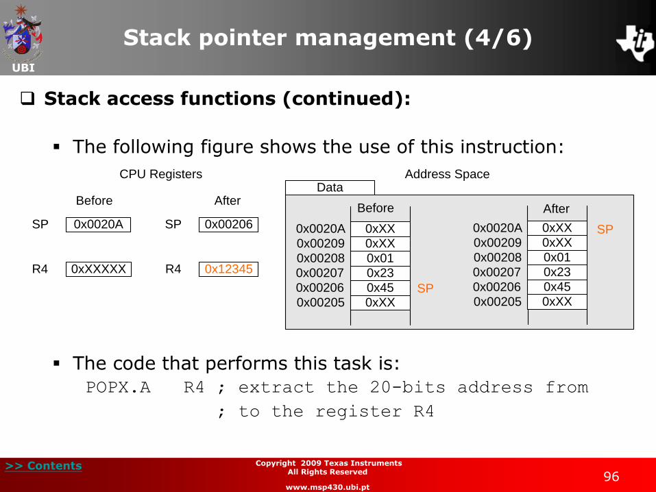
Stack access functions (continued):
The following figure shows the use of this instruction:
The code that performs this task is:
POPX.A R4 ; extract the 20-bits address from
; to the register R4
CPU Registers
Before After
Address SpaceData
0x0020ASP 0x00206SP
0xXXXXXR4 0x12345R4
Before
0xXX
0xXXSP
0x00205
0x00206
0x00207
0x45
0x23
0x010x00208
0x00209
0x0020A
0xXXSP
After
0x00205
0x00206
0x00207
0x00208
0x00209
0x0020A 0xXX
0xXX
0x45
0x23
0x01
0xXX
UBI
>> Contents 97
Copyright 2009 Texas Instruments All Rights Reserved
www.msp430.ubi.pt
Stack pointer management (5/6)
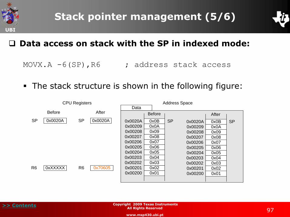
Data access on stack with the SP in indexed mode:
MOVX.A -6(SP),R6 ; address stack access
The stack structure is shown in the following figure:
CPU Registers
Before After
Address Space
0x0B
0x06
0x01
SP
Before After
Data
0x00204
0x00205
0x00206
0x00207
0x00200
0x00201
0x00202
0x00203
0x02
0x03
0x04
0x05
0x07
0x08
0x090x00208
0x00209
0x0020A
0x0A
0x0020ASP 0x0020ASP
0xXXXXXR4 0x0000BR4
0xXXXXXR5 0x00A09R5
0xXXXXXR6 0x70605R6
0x0B
0x06
0x01
SP
0x00204
0x00205
0x00206
0x00207
0x00200
0x00201
0x00202
0x00203
0x02
0x03
0x04
0x05
0x07
0x08
0x090x00208
0x00209
0x0020A
0x0A
UBI
>> Contents 98
Copyright 2009 Texas Instruments All Rights Reserved
www.msp430.ubi.pt
Stack pointer management (6/6)
Data access on stack with the SP in indexed mode (cont.):
The code moves the contents of the address SP - 6 = 0x00204 to register R6;
The entire procedure is performed without modifying the register SP value.
UBI
>> Contents 99
Copyright 2009 Texas Instruments All Rights Reserved
www.msp430.ubi.pt
Routines
Invoking a routine:
The MSP430X CPU also has the instruction:
CALLA destination
This instruction decrements the register SP by four to store the return address;
The register PC is then loaded with the routine address and the routine executed;
The return is performed by the instruction RETA.
UBI
>> Contents 100
Copyright 2009 Texas Instruments All Rights Reserved
www.msp430.ubi.pt
Interrupts
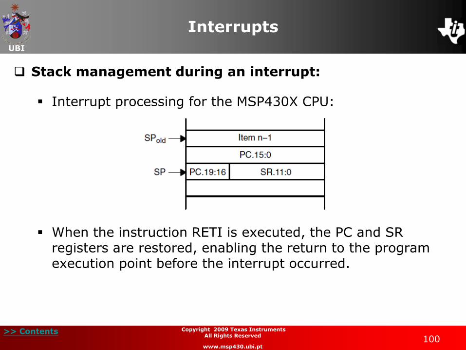
Stack management during an interrupt:
Interrupt processing for the MSP430X CPU:
When the instruction RETI is executed, the PC and SR registers are restored, enabling the return to the program execution point before the interrupt occurred.