mso/ds1000z - aparate masura si controlmso/ds1000z series is a high-performance and economic digital...
TRANSCRIPT

MSO/DS1000Z series is a high-performance and economic digital oscilloscope designed for the designing, debugging and educational requirements of the mainstream digital oscilloscope market. Wherein, the mixed signal digital oscilloscope aimed at the embedded design and test fields is equipped with 16 digital channels and allows users to measure analog and digital signals at the same time.
Digital OscilloscopeSeriesMSO/DS1000Z
RIGOL TECHNOLOGIES, INC.
Analog channel bandwidth: 100 MHz, 70 MHz, 50 MHz 4 analog channels, 16 digital channels (for MSO1000Z and MSO
upgradable for DS1000Z Plus) Real-time sample rate up to 1 GSa/s Memory depth up to 12 Mpts (standard)/24 Mpts (optional) Up to 30,000 wfms/s waveform capture rate Up to 60,000 frames hardware real-time waveform recording
and playback functions (optional) Innovative "UltraVision" technology MSO field upgradable with MSO1000Z upgrade package
(MSO upgrade option, only for DS1000Z Plus) Various trigger and bus decoding functions Low noise floor, vertical scale range: 1 mV/div to 10 V/div Built-in dual-channel 25 MHz function/arbitrary waveform generator
(only for digital oscilloscope with source channels) Various interfaces: USB Host&Device, LAN (LXI), AUX,
USB-GPIB (optional) Compact size, light weight, easy to use 7 inch WVGA (800x480) TFT LCD, intensity graded color display

MSO/DS1000Z Series Digital Oscilloscope
Deeper Memory Depth (standard 12 Mpts, optional 24 Mpts) Higher Waveform Capture Rate (up to 30,000 wfms/s) Real-time Waveform Recording&Playback (up to 60,000 frames, optional) Intensity Graded Color Display
Innovative UltraVision Technology(Analog Channel)
Models and Key Specifications
Product Dimensions: Width × Height × Depth=313.1 mm × 160.8 mm × 122.4 mm Weight: 3.2 kg ± 0.2 kg(Without Package)
7 inch WVGA (800X480) TFT display, intensity graded color display
4 analog channels
Built-in source control key (digital oscilloscope with
source channels)
16 digital channels (for MSO1000Z and MSO upgradable for DS1000Z Plus)
Model DS1054ZDS1074Z Plus DS1074Z-S Plus DS1104Z Plus DS1104Z-S Plus
MSO1074Z MSO1074Z-S MSO1104Z MSO1104Z-S
Analog BW 50 MHz 70 MHz 100MHz
Number of Analog Channels 4
Number of Digital Channels 16 digital channels for MSO1000Z; MSO upgradable for DS1000Z Plus
Max. Sample RateAnalog channel: 1 GSa/s (single-channel),
500 MSa/s (dual-channel), 250 MSa/s (three/four-channel)Digital channel: 1 GSa/s (8-channel), 500 MSa/s (16-channel)
Max. Memory Depth
Analog channel:standard 12 Mpts (single-channel), 6 Mpts (dual-channel), 3 Mpts (3/4-channel); optional 24 Mpts (single-channel), 12 Mpts (dual-channel), 6 Mpts (3/4-channel)
Digital channel: standard 12 Mpts (8-channel), 6 Mpts (16-channel); optional 24 Mpts (8-channel), 12 Mpts (16-channel)
Max. Waveform Capture Rate 30,000 wfms/s
Hardware Real-time Waveform Recording, Playback and Analysis Functions
Up to 60,000 frames (optional)
Standard Probes RP2200 150 MHz Passive HighZ Probe: 4 sets; 1 set RPL1116 LA Probe for MSO1000Z
Built-in Dual-channel 25 MHz Source No Yes No Yes
None
1 RIGOL

4 analog channels, 16 digital channels (for MSO1000Z and MSO upgradable for DS1000Z Plus)
UltraVision: deeper memory (standard 12 Mpts, optional 24 Mpts)
UltraVision: up to 30,000 wfms/s waveform capture rate
UltraVision: waveform recording and playback functions (optional)
UltraVision: intensity graded color display
A variety of trigger functions
Optional serial bus trigger and decoding functions (RS232/UART, I2C, SPI)
Built-in dual-channel 25 MHz source (MSO1XX4Z-S and DS1XX4Z-S Plus)
*Do not include the 50 MHz bandwidth model
2 RIGOL
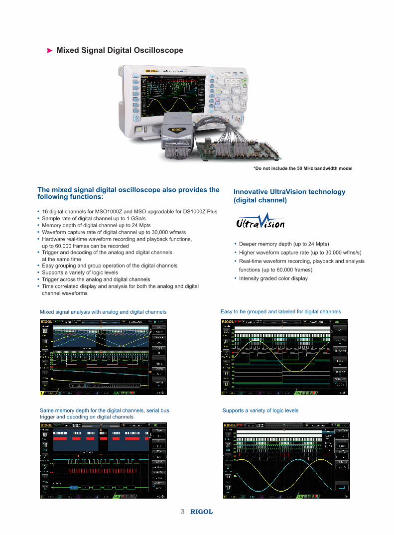
Mixed Signal Digital Oscilloscope
The mixed signal digital oscilloscope also provides the following functions:
16 digital channels for MSO1000Z and MSO upgradable for DS1000Z Plus Sample rate of digital channel up to 1 GSa/s Memory depth of digital channel up to 24 Mpts Waveform capture rate of digital channel up to 30,000 wfms/s Hardware real-time waveform recording and playback functions,
up to 60,000 frames can be recorded Trigger and decoding of the analog and digital channels
at the same time Easy grouping and group operation of the digital channels Supports a variety of logic levels Trigger across the analog and digital channels Time correlated display and analysis for both the analog and digital
channel waveforms
Deeper memory depth (up to 24 Mpts) Higher waveform capture rate (up to 30,000 wfms/s) Real-time waveform recording, playback and analysis
functions (up to 60,000 frames) Intensity graded color display
Mixed signal analysis with analog and digital channels
Same memory depth for the digital channels, serial bus trigger and decoding on digital channels
Supports a variety of logic levels
Easy to be grouped and labeled for digital channels
Innovative UltraVision technology (digital channel)
*Do not include the 50 MHz bandwidth model
3 RIGOL

50 Ω impedance adapter (2 W, 1 GHz)
RIGOL Passive Probes RIGOL Active & Current Probes
Logic analysis probe (for mixed signal digital oscilloscope)
RIGOL Probes and Accessories Supported by MSO/DS1000Z Series
Model Number Type Description
RP1001C
Current Probe
BW: DC to 300 kHz Max. InputDC: ±100 A,AC P-P: 200 A,AC RMS: 70 A Compatibility: all RIGOL scopes.
RP1002C
Current Probe
BW: DC to 1 MHz Max. inputDC: ±70 A,AC P-P: 140 A,AC RMS: 50 A Compatibility: all RIGOL scopes.
RP1003C
Current Probe
BW: DC to 50 MHz Max. inputAC P-P: 50 A (Noncontinuous)AC RMS: 30 ACompatibility: all RIGOL scopes.Must order RP1000P power supply.
RP1004C
Current Probe
BW: DC to 100 MHz Max. inputAC P-P: 50 A (Noncontinuous)AC RMS: 30 A,Compatibility: all RIGOL scopes.Must order RP1000P power supply.
RP1005C
Current Probe
BW: DC to 10 MHz, Max. inputAC P-P: 300 A (Noncontinuous), 500 A (@pulse width ≤30 us),AC RMS: 150 ACompatibility: all RIGOL scopes.Must order RP1000P power supply.
RP1000P
Power Supply
Power supply for RP1003C, RP1004C, RP1005C, support 4 channels.
RP1025D
High Voltage Differential Probe
BW: 25 MHzMax. Voltage ≤1400 VppCompatibility: all RIGOL scopes.
RP1050D
High Voltage Differential Probe
BW: 50 MHzMax. Voltage ≤7000 VppCompatibility: all RIGOL scopes.
RP1100D
High Voltage Differential Probe
BW: 100 MHzMax. Voltage ≤7000 VppCompatibility: all RIGOL scopes.
Model Number Type Description
RP2200
High Z Probe
1X: DC to 7 MHz10X: DC to 150 MHzCompatibility: all RIGOL scopes.
RP3300A
High Z Probe
10X: DC to 350 MHzCompatibility: all RIGOL scopes.
RP3500A
High Z Probe
DC to 500 MHzCompatibility: all RIGOL scopes.
RP1300H
High Voltage Probe
DC to 300 MHzCAT I 2000 V (DC+AC), CAT II 1500 V (DC+AC) Compatibility: all RIGOL scopes.
RP1010H
High Voltage Probe
DC to 40 MHzDC: 0 to 10 kV DC,AC: pulse ≤20 kVp-p, AC: sine wave ≤7 kVrms Compatibility: all RIGOL scopes.
High Voltage Probe
DC to 150 MHzDC+AC Peak: 18 kV CAT II AC RMS: 12 kV CAT II Compatibility: all RIGOL scopes.
RP1018H
RPL1116
RT50J
Logic Analysis Probe
Adapter
4 RIGOL

SpecificationsAll the specifications are guaranteed except parameters marked with “Typical” and the oscilloscope needs to operate for more than 30 minutes under the specified operation temperature.
Sample
Sample Mode Real-time sample
Real-time Sample Rate
Analog channel: 1 GSa/s (single-channel),500 MSa/s (dual-channel), 250 MSa/s (three/four-channel) Digital channel: 1 GSa/s (8-channel), 500 MSa/s (16-channel)
Peak Detect Analog channel: 4 nsDigital channel: 4 ns
Averaging After all the channels finish N samples at the same time, N can be 2, 4, 8, 16, 32, 64, 128, 256, 512 or 1024.
High Resolution 12 bit (max)
Interpolation Sin(x)/x (optional)
Min Detect Pulse Width Digital channel: 10 ns
Memory Depth
Analog channel: standard 12 Mpts (single-channel), 6 Mpts (dual-channel), 3 Mpts (three/four-channel); optional 24 Mpts (single-channel), 12 Mpts (dual-channel), 6 Mpts (three/four-channel)Digital channel: standard 12 Mpts (8-channel), 6 Mpts (16-channel); optional 24 Mpts (8-channel), 12 Mpts (16-channel)
Input
Number of ChannelsMSO1XX4Z/1XX4Z-S: 4 analog channels, 16 digital channelsDS1XX4Z Plus/1XX4Z-S Plus: 4 analog channels, MSO upgradableDS1054Z: 4 analog channels
Input Coupling DC, AC or GND
Input Impedance Analog channel: (1 MΩ±1%) || (15 pF±3 pF)Digital channel: (100 kΩ±1%) || 8 pF±3 pF)
Probe Attenuation Coefficient Analog channel: 0.01X to 1000X, in 1-2-5 step
Max Input Voltage (1MΩ)
Analog channel: CAT I 300 Vrms, CAT II 100 Vrms, transient overvoltage 1000 VpkWith RP2200 10:1 probe: CAT II 300 Vrms Digital channel: CAT I 40 Vrms, transient overvoltage 800 Vpk
HorizontalTimebase Scale 5 ns/div to 50 s/div
Max Record Length 24 Mpts (optional)
Timebase Accuracy[1] ≤ ± 25 ppm
Clock Drift ≤ ± 5 ppm/year
Max Delay Range Negative delay: ≥1/2 screen widthPositive delay: 1 s to 500 s
Timebase Mode YT, XY, Roll
Number of X-Ys 1
Waveform Capture Rate[2] 30,000 wfms/s (dots display)
Zero Offset ±0.5div*minimum time base scale
Vertical
Bandwidth (-3dB)MSO1104Z/1104Z-S and DS1104Z Plus/1104Z-S Plus: DC to 100 MHzMSO1074Z/1074Z-S and DS1074Z Plus/1074Z-S Plus: DC to 70 MHz DS1054Z: DC to 50 MHz
5 RIGOL

Single-shot BandwidthMSO1104Z/1104Z-S and DS1104Z Plus/1104Z-S Plus: DC to 100 MHzMSO1074Z/1074Z-S and DS1074Z Plus/1074Z-S Plus: DC to 70 MHz DS1054Z: DC to 50 MHz
Vertical Resolution Analog channel: 8 bitsDigital channel: 1 bit
Vertical Scale(Probe ratio is 1X) 1 mV/div to 10 V/div
Offset Range(Probe ratio is 1X)
1 mV/div to 499 mV/div: ± 2 V500 mV/div to 10 V/div: ± 100 V
Bandwidth Limit[1] 20 MHzLow Frequency Response (AC coupling, -3dB) ≤5 Hz (on BNC)
Calculated Rise Time[1]MSO1104Z/1104Z-S and DS1104Z Plus/1104Z-S Plus: 3.5 nsMSO1074Z/1074Z-S and DS1074Z Plus/1074Z-S Plus: 5 nsDS1054Z: 7 ns
DC Gain Accuracy <10 mV: ±4% full scale≥10 mV: ±3% full scale
DC Offset Accuracy ±0.1 div ± 2 mV ± 1% offset
Channel to Channel Isolation DC to maximum bandwidth: >40 dB
Vertical (Digital Channel)(Applicable to MSO1000Z and DS1000Z Plus with MSO Upgrade Option)Threshold Adjustable threshold of 8 channels per group
Threshold Selection
TTL (1.4 V)
5.0 V CMOS (+2.5 V), 3.3 V CMOS (+1.65 V)
2.5 V CMOS (+1.25 V), 1.8 V CMOS (+0.9 V)
ECL (-1.3 V)
PECL (+3.7 V)
LVDS (+1.2 V)
0 V
User
Threshold Range ±15.0 V, in 10 mV step
Threshold Accuracy ±(100 mV + 3% of threshold setting)
Dynamic Range ±10.0 V + threshold
Min Voltage Swing 500 mVpp
Vertical Resolution 1 bit
TriggerTrigger Level Range ±5 div from the center of the screen
Trigger Mode Auto, Normal, Single
Holdoff Range 16 ns to 10 s
High Frequency Rejection[1] 75 kHz
Low Frequency Rejection[1] 75 kHz
Trigger Sensitivity[1] 1.0 div (below 5 mV or noise rejection is enabled)0.3 div (above 5 mV and noise rejection is disabled)
Edge Trigger
Edge Type Rising, Falling, Rising/Falling
Pulse Trigger
Pulse Condition Positive Pulse Width (greater than, lower than, within specified interval)Negative Pulse Width (greater than, lower than, within specified interval)
Pulse Width 8 ns to 10 s
Runt Trigger (Optional)
Pulse Width Condition None, >, <, <>
Polarity Positive, Negative
Pulse Width Range 8 ns to 10 s
Window Trigger (Optional)
Windows Type Rising, Falling, Rising/Falling
6 RIGOL

Trigger Position Enter, Exit, Time
Windows Time 8 ns to 10 s
Nth Edge Trigger (Optional)
Edge Type Rising, Falling
Idle Time 16 ns to 10 s
Edge Number 1 to 65535
Slope Trigger
Slope Condition Positive Slope (greater than, lower than, within specified interval)Negative Slope (greater than, lower than, within specified interval)
Time Setting 8 ns to 10 s
Video Trigger
Signal Standard NTSC, PAL/SECAM, 480P, 576P
Pattern Trigger
Pattern Setting H, L, X, Rising, Falling
Delay Trigger (Optional)
Edge Type Rising, Falling
Delay Type >, <, <>, ><
Delay Time 8 ns to 10 s
TimeOut Trigger (Optional)
Edge Type Rising, Falling, Rising/Falling
TimeOut Value 16 ns to 10 s
Duration Trigger
Pattern H, L, X
Trigger Condition >, <, <>
Duration Time 8 ns to 10 s
Setup/Hold Trigger (Optional)
Edge Type Rising, Falling
Data Pattern H, L,X
Setup Time 8 ns to 1 s
Hold Time 8 ns to 1 s
RS232/UART Trigger (Optional)
Polarity Normal, Invert
Trigger Condition Start, Error, Check Error, Data
Baud Rate 2400 bps, 4800 bps, 9600 bps, 19200 bps, 38400 bps, 57600 bps, 115200 bps, 230400 bps, 460800 bps, 921600 bps, 1 Mbps and User
Data Bits 5 bits, 6 bits, 7 bits, 8 bits
I2C Trigger (Optional)
Trigger Condition Start, Restart, Stop, Missing Ack, Address, Data, A&D
Address Bits 7 bits, 8 bits, 10 bits
Address Range 0 to 127, 0 to 255, 0 to 1023
Byte Length 1 to 5
SPI Trigger (Optional)
Trigger Condition Timeout, CS
Timeout Value 16 ns to 10 s
Data Bits 4 bit to 32 bit
Data Line Setting H, L, X
7 RIGOL

Measure
Cursor
Manual modeVoltage deviation between cursors ( △V ) Time deviation between cursors ( △T )Reciprocal of △T (Hz) (1/ △T )
Track mode Voltage and time values of the waveform point
Auto mode Allow to display cursors during auto measurement
Auto Measurement
Analog channel:Period, Frequency, Rise Time, Fall Time, Positive Pulse Width, Negative Pulse Width, Positive Duty Cycle, Negative Duty Cycle, tVmax, tVmin, Positive Rate, Negative Rate, Delay 12 , Delay 12 , Phase 12 , Phase 12 , Maximum, Minimum, Peak-Peak Value, Top Value, Bottom Value, Amplitude, Upper Value, Middle Value, Lower Value, Average, Vrms, Overshoot, Pre-shoot, Area, Period Area, Period Vrms, VarianceDigital channel:Period, Frequency, Positive Pulse Width, Negative Pulse Width, Positive Duty Cycle, Negative Duty Cycle, Delay 12 , Delay 12 , Phase 12 , Phase 12
Number of Measurements Display 5 measurements at the same time
Measurement Range Screen or cursor
Measurement Statistic Average, Max, Min, Standard Deviation, Number of Measurements
Counter Hardware 6 bit counter (channels are selectable)
Math OperationWaveform Operation A+B, A-B, A×B, A/B, FFT, A&&B, A||B, A^B, !A, Intg, Diff, Sqrt, Lg, Ln, Exp, Abs
FFT Window Rectangle, Hanning, Blackman, Hamming,Flat Top,Triangle
FFT Display Half, Full
FFT Vertical Scale dB/dBm, Vrms
Number of Busesfor Decoding 2
Decoding Type Parallel (standard), RS232/UART (option), I2C (option), SPI (option)
DisplayDisplay Type 7.0 inch TFT LCD display
Display Resolution 800 horizontal × RGB × 480 vertical pixel
Display Color 16 million color (24 bit true color)
Persistence Time Min, 100 ms, 200 ms, 500 ms, 1 s, 5 s, 10 s, Infinite
Display Type Dots, Vectors
I/OStandard Ports USB Host, USB Device, LAN, Aux Output (TrigOut/PassFail), GPIB (extended via the USB Host interface)
Signal Source ( (Applicable to Digital Oscilloscopes with Source Channels))Number of Channels 2
Sample Rate 200 MSa/s
Vertical Resolution 14 bits
Max. Frequency 25 MHz
Standard Waveform Sine, Square, Pulse, Ramp, Noise, DC
Arbitrary Waveform Since, Exp.Rise, EXP.Fall, ECG, Gauss, Lorentz, Haversine
Sine
Frequency Range 0.1 Hz to 25 MHz
Flatness ±0.5 dB (relative to 1 kHz)
Harmonic Distortion -40 dBc
Stray (Non-harmonic) -40 dBc
Total Harmonic Distortion 1%
S/N Ratio 40 dB
8 RIGOL

Square/Pulse
Frequency Range Square: 0.1 Hz to 15 MHzPulse: 0.1 Hz to 1 MHz
Rise/Fall time <15 ns
Overshoot <5%
Duty Cycle Square: always be 50%Pulse: 10% to 90% adjustable
Duty Cycle Resolution 1% or 10 ns (the larger of the two)
Min. Pulse Width 20 ns
Pulse Width Resolution 10 ns or 5 bits (the larger of the two)
Jitter 500 ps
Ramp
Frequency Range 0.1 Hz to 100 kHz
Linearity 1%
Symmetry 0 to 100%
Noise[1] Bandwidth 25 MHz
Built-in Waveform Frequency Range 0.1 Hz to 1 MHz
Arbitrary WaveformFrequency Range 0.1 Hz to 10 MHz
Waveform Length 2 to 16k pts
FrequencyAccuracy 100 ppm (lower than 10 kHz)
50 ppm (greater than 10 kHz)
Resolution 0.1 Hz or 4 bit, the larger of the two
Amplitude
Output Range 20 mVpp to 5 Vpp, High-resistance10 mVpp to 2.5 Vpp, 50 Ω
Resolution 100 μV or 3 bit, the greater of the two
Accuracy 2% (1 kHz)
DC Offset
Range ±2.5 V, HighZ±1.25 V, 50 Ω
Resolution 100 μV or 3 bit, the larger of the two
Accuracy 2% (1 kHz)
Modulation AM, FM
General SpecificationsProbe Compensation Output
Output Voltage[1] About 3 V, peak-peak
Frequency[1] 1 kHz
Power
Power Voltage 100 V to 240 V, 45 Hz to 440 Hz
Power Maximum 50 W
Fuse 2 A, T degree, 250 V
Environment
Temperature Range Operating: 0℃ to +50℃
Non-operating: -40℃ to +70℃
Cooling Method Fan cooled
Humidity Range 0℃ to +30℃ : ≤95℃ relative humidity
+35℃ to +40℃ : ≤75℃ relative humidity
+40℃ to +50℃ : ≤45℃ relative humidity
Altitude Operating: under 3,000 meters
Non-operating: under 15,000 meters
Mechanical
Dimensions[3] Width × Height × Depth = 313.1 mm × 160.8 mm × 122.4 mm
Weight[4] Without package 3.2 kg ± 0.2 kg
With package 3.8 kg ± 0.5 kg
9 RIGOL
Calibration Interval
The recommended calibration interval is one year.
Regulation Standards
Electromagnetic Compatibility 2004/108/EC Execution standard EN 61326-1:2006 EN 61326-2-1:2006
Safety UL 61010-1:2004; CAN/CSA-C22.2 NO. 61010-1-2004;EN 61010-1:2001; IEC 61010-1:2001
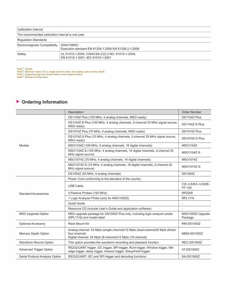
Ordering Information
Note[1]: Typical.Note[2]: Maximum value. 50 ns, single-channel mode, dots display, auto memory depth.Note[3]: Supporting legs and handle folded, knob height included.Note[4]: Standard configuration.
Description Order Number
Models
DS1104Z Plus (100 MHz, 4 analog channels, MSO ready) DS1104Z Plus
DS1104Z-S Plus (100 MHz, 4 analog channels, 2-channel 25 MHz signal source, MSO ready) DS1104Z-S Plus
DS1074Z Plus (70 MHz, 4 analog channels, MSO ready) DS1074Z Plus
DS1074Z-S Plus (70 MHz, 4 analog channels, 2-channel 25 MHz signal source, MSO ready) DS1074Z-S Plus
MSO1104Z (100 MHz, 4 analog channels, 16 digital channels) MSO1104Z
MSO1104Z-S (100 MHz, 4 analog channels, 16 digital channels, 2-channel 25 MHz signal source) MSO1104Z-S
MSO1074Z (70 MHz, 4 analog channels, 16 digital channels) MSO1074Z
MSO1074Z-S (70 MHz, 4 analog channels, 16 digital channels, 2-channel 25 MHz signal source) MSO1074Z-S
DS1054Z (50 MHz, 4 analog channels) DS1054Z
Standard Accessories
Power Cord conforming to the standard of the country -
USB Cable CB-USBA-USBB-FF-150
4 Passive Probes (150 MHz) RP2200
1 Logic Analyzer Probe (only for MSO1000Z) RPL1116
Quick Guide -
Resource CD (include User’s Guide and application software) -
MSO Upgrade Option MSO upgrade package for DS1000Z Plus only, including logic analyzer probe (RPL1116) and model label
MSO1000Z Upgrade Package
Optional Accessory Rack Mount Kit RM-DS1000Z
Memory Depth OptionAnalog channel: 24 Mpts (single channel)/12 Mpts (dual-channel)/6 Mpts (three/four channel)Digital channel: 24 Mpts (8-channel)/12 Mpts (16-channel)
MEM-DS1000Z
Waveform Record Option This option provides the waveform recording and playback function. REC-DS1000Z
Advanced Trigger Option RS232/UART trigger, I2C trigger, SPI trigger, Runt trigger, Window trigger, Nth edge trigger, delay trigger, timeout trigger, Setup/Hold trigger AT-DS1000Z
Serial Protocol Analysis Option RS232/UART, I2C and SPI trigger and decoding functions SA-DS1000Z

WarrantyThree -year warranty, excluding probes and accessories.
Standard Software
Ultra Sigma Ultra Scope
Real-time monitoring of waveform and status; support multi-instrument and multi-window display With virtual panel feature Supports multi-interface remote control
RIGOL general PC software platform Multi-instrument and multi-interface resource management With SCPI remote command tool
HEADQUARTERRIGOL TECHNOLOGIES, INC.No.156,Cai He Village,Sha He Town,Chang Ping District, Beijing,102206 P.R.ChinaTel:+86-10-80706688Fax:+86-10-80705070E l e c t r o n i c M e a s u r e m e n t Instrument service and support email:[email protected] Analysis Instrument service and support email:[email protected]
EUROPERIGOL TECHNOLOGIES GmbHLindbergh str. 482178 PuchheimGermanyTel: 0049- 89/89418950Email: [email protected]
NORTH AMERICARIGOL TECHNOLOGIES,USA INC.10200 SW Allen Blvd, Suite CBeaverton, OR 97005, USAToll free: 877-4-RIGOL-1Office: (440) 232-4488Fax: (216)-754-8107Email: [email protected]
JAPANRIGOL TECHNOLOGIES JAPAN G.K.Tonematsu Bldg. 5F, 2-33-8 Nihonbashi-Ningyocho, Chuo-ku,Tokyo 103-0013 JapanTel: +81-3-6264-9251Fax: +81-3-6264-9252Email: [email protected]
RIGOL® is the registered trademark of RIGOL Technologies, Inc. Product information in this document subject to update without notice. For the latest information about RIGOL's products, applications and services, please contact local RIGOL office or access RIGOL official website: www.rigol.com