mso/dpo5000/b, dpo7000/c, dpo70000/b/c/d/dx/sx, …
TRANSCRIPT

xx
MSO/DPO5000/B, DPO7000/C, DPO70000/B/C/D/DX/SX,DSA70000/B/C/D, and MSO70000/C/DX SeriesDigital Oscilloscopes
ZZZ
Programmer Manual
*P077001022*
077-0010-22


MSO/DPO5000/B, DPO7000/C, DPO70000/B/C/D/DX/SX,DSA70000/B/C/D, and MSO70000/C/DX SeriesDigital Oscilloscopes
ZZZ
Programmer Manual
xx
www.tek.com
077-0010-22

Copyright © Tektronix. All rights reserved. Licensed software products are owned by Tektronix or its subsidiariesor suppliers, and are protected by national copyright laws and international treaty provisions.
Tektronix products are covered by U.S. and foreign patents, issued and pending. Information in this publicationsupersedes that in all previously published material. Specifications and price change privileges reserved.
TEKTRONIX and TEK are registered trademarks of Tektronix, Inc.
UltraSync, FastFrame, OpenChoice, iView, Pinpoint, RT-Eye, MyScope, TekLink, TekVPI, MultiView Zoom,and DPX are trademarks of Tektronix, Inc.
DPO7000C, MSO/DPO5000/B, DPO7000, DPO70000/B/C/D/DX/SX, DSA70000/B/C/D, and MSO70000/C/DXSeries Programmer Online Help, 076-0021-22
Contacting Tektronix
Tektronix, Inc.14150 SW Karl Braun DriveP.O. Box 500Beaverton, OR 97077USA
For product information, sales, service, and technical support:In North America, call 1-800-833-9200.Worldwide, visit www.tek.com to find contacts in your area.

Table of Contents
Preface .. . . . . . . . . . . . . . . . . . . . . . . . . . . . . . . . . . . . . . . . . . . . . . . . . . . . . . . . . . . . . . . . . . . . . . . . . . . . . . . . . . . . . . . . . . . . . . . . . . . . . . . . . . . . . iiiGetting started.. . . . . . . . . . . . . . . . . . . . . . . . . . . . . . . . . . . . . . . . . . . . . . . . . . . . . . . . . . . . . . . . . . . . . . . . . . . . . . . . . . . . . . . . . . . . . . . . . . . . 1-1
Setting up remote communications . . . . . . . . . . . . . . . . . . . . . . . . . . . . . . . . . . . . . . . . . . . . . . . . . . . . . . . . . . . . . . . . . . . . . . . . 1-2Command syntax .. . . . . . . . . . . . . . . . . . . . . . . . . . . . . . . . . . . . . . . . . . . . . . . . . . . . . . . . . . . . . . . . . . . . . . . . . . . . . . . . . . . . . . . . . . . . . . . . 2-1
Backus-Naur Form notation . . . . . . . . . . . . . . . . . . . . . . . . . . . . . . . . . . . . . . . . . . . . . . . . . . . . . . . . . . . . . . . . . . . . . . . . . . . . . . . . 2-1Command and query structure . . . . . . . . . . . . . . . . . . . . . . . . . . . . . . . . . . . . . . . . . . . . . . . . . . . . . . . . . . . . . . . . . . . . . . . . . . . . . 2-1Clearing the instrument . . . . . . . . . . . . . . . . . . . . . . . . . . . . . . . . . . . . . . . . . . . . . . . . . . . . . . . . . . . . . . . . . . . . . . . . . . . . . . . . . . . . . 2-3Command entry . . . . . . . . . . . . . . . . . . . . . . . . . . . . . . . . . . . . . . . . . . . . . . . . . . . . . . . . . . . . . . . . . . . . . . . . . . . . . . . . . . . . . . . . . . . . . . 2-3Constructed mnemonics. . . . . . . . . . . . . . . . . . . . . . . . . . . . . . . . . . . . . . . . . . . . . . . . . . . . . . . . . . . . . . . . . . . . . . . . . . . . . . . . . . . . . 2-5Argument types . . . . . . . . . . . . . . . . . . . . . . . . . . . . . . . . . . . . . . . . . . . . . . . . . . . . . . . . . . . . . . . . . . . . . . . . . . . . . . . . . . . . . . . . . . . . . . 2-6
Command groups .. . . . . . . . . . . . . . . . . . . . . . . . . . . . . . . . . . . . . . . . . . . . . . . . . . . . . . . . . . . . . . . . . . . . . . . . . . . . . . . . . . . . . . . . . . . . . . . . 2-9Acquisition command group .. . . . . . . . . . . . . . . . . . . . . . . . . . . . . . . . . . . . . . . . . . . . . . . . . . . . . . . . . . . . . . . . . . . . . . . . . . . . . . 2-9Alias command group .. . . . . . . . . . . . . . . . . . . . . . . . . . . . . . . . . . . . . . . . . . . . . . . . . . . . . . . . . . . . . . . . . . . . . . . . . . . . . . . . . . . . 2-11Bus command group.. . . . . . . . . . . . . . . . . . . . . . . . . . . . . . . . . . . . . . . . . . . . . . . . . . . . . . . . . . . . . . . . . . . . . . . . . . . . . . . . . . . . . . 2-12Calibration command group . . . . . . . . . . . . . . . . . . . . . . . . . . . . . . . . . . . . . . . . . . . . . . . . . . . . . . . . . . . . . . . . . . . . . . . . . . . . . . 2-16Cursor command group .. . . . . . . . . . . . . . . . . . . . . . . . . . . . . . . . . . . . . . . . . . . . . . . . . . . . . . . . . . . . . . . . . . . . . . . . . . . . . . . . . . 2-17Diagnostics command group .. . . . . . . . . . . . . . . . . . . . . . . . . . . . . . . . . . . . . . . . . . . . . . . . . . . . . . . . . . . . . . . . . . . . . . . . . . . . 2-19Digital command group . . . . . . . . . . . . . . . . . . . . . . . . . . . . . . . . . . . . . . . . . . . . . . . . . . . . . . . . . . . . . . . . . . . . . . . . . . . . . . . . . . 2-20Display control command group .. . . . . . . . . . . . . . . . . . . . . . . . . . . . . . . . . . . . . . . . . . . . . . . . . . . . . . . . . . . . . . . . . . . . . . . . 2-21E-mail command group .. . . . . . . . . . . . . . . . . . . . . . . . . . . . . . . . . . . . . . . . . . . . . . . . . . . . . . . . . . . . . . . . . . . . . . . . . . . . . . . . . . 2-23Error Detector command group . . . . . . . . . . . . . . . . . . . . . . . . . . . . . . . . . . . . . . . . . . . . . . . . . . . . . . . . . . . . . . . . . . . . . . . . . . 2-25File system command group. . . . . . . . . . . . . . . . . . . . . . . . . . . . . . . . . . . . . . . . . . . . . . . . . . . . . . . . . . . . . . . . . . . . . . . . . . . . . . 2-34Hard copy command group .. . . . . . . . . . . . . . . . . . . . . . . . . . . . . . . . . . . . . . . . . . . . . . . . . . . . . . . . . . . . . . . . . . . . . . . . . . . . . . 2-35Histogram command group.. . . . . . . . . . . . . . . . . . . . . . . . . . . . . . . . . . . . . . . . . . . . . . . . . . . . . . . . . . . . . . . . . . . . . . . . . . . . . . 2-36Horizontal command group.. . . . . . . . . . . . . . . . . . . . . . . . . . . . . . . . . . . . . . . . . . . . . . . . . . . . . . . . . . . . . . . . . . . . . . . . . . . . . . 2-37Limit Test command group .. . . . . . . . . . . . . . . . . . . . . . . . . . . . . . . . . . . . . . . . . . . . . . . . . . . . . . . . . . . . . . . . . . . . . . . . . . . . . . 2-40Link Training command group .. . . . . . . . . . . . . . . . . . . . . . . . . . . . . . . . . . . . . . . . . . . . . . . . . . . . . . . . . . . . . . . . . . . . . . . . . . 2-41Low Speed Serial Trigger command group .. . . . . . . . . . . . . . . . . . . . . . . . . . . . . . . . . . . . . . . . . . . . . . . . . . . . . . . . . . . . 2-42Mask command group.. . . . . . . . . . . . . . . . . . . . . . . . . . . . . . . . . . . . . . . . . . . . . . . . . . . . . . . . . . . . . . . . . . . . . . . . . . . . . . . . . . . . 2-48Math command group .. . . . . . . . . . . . . . . . . . . . . . . . . . . . . . . . . . . . . . . . . . . . . . . . . . . . . . . . . . . . . . . . . . . . . . . . . . . . . . . . . . . . 2-52Measurement command group .. . . . . . . . . . . . . . . . . . . . . . . . . . . . . . . . . . . . . . . . . . . . . . . . . . . . . . . . . . . . . . . . . . . . . . . . . . 2-54Miscellaneous command group . . . . . . . . . . . . . . . . . . . . . . . . . . . . . . . . . . . . . . . . . . . . . . . . . . . . . . . . . . . . . . . . . . . . . . . . . . 2-57Save and Recall command group . . . . . . . . . . . . . . . . . . . . . . . . . . . . . . . . . . . . . . . . . . . . . . . . . . . . . . . . . . . . . . . . . . . . . . . . 2-59Save On command Group . . . . . . . . . . . . . . . . . . . . . . . . . . . . . . . . . . . . . . . . . . . . . . . . . . . . . . . . . . . . . . . . . . . . . . . . . . . . . . . . 2-60Search and Mark command group .. . . . . . . . . . . . . . . . . . . . . . . . . . . . . . . . . . . . . . . . . . . . . . . . . . . . . . . . . . . . . . . . . . . . . . 2-61Status and Error command group . . . . . . . . . . . . . . . . . . . . . . . . . . . . . . . . . . . . . . . . . . . . . . . . . . . . . . . . . . . . . . . . . . . . . . . . 2-79Trigger command group . . . . . . . . . . . . . . . . . . . . . . . . . . . . . . . . . . . . . . . . . . . . . . . . . . . . . . . . . . . . . . . . . . . . . . . . . . . . . . . . . . 2-80Vertical command group . . . . . . . . . . . . . . . . . . . . . . . . . . . . . . . . . . . . . . . . . . . . . . . . . . . . . . . . . . . . . . . . . . . . . . . . . . . . . . . . . . 2-94Waveform Transfer command group . . . . . . . . . . . . . . . . . . . . . . . . . . . . . . . . . . . . . . . . . . . . . . . . . . . . . . . . . . . . . . . . . . . . 2-98
MSO/DPO5000/B, DPO7000/C, DPO70000/B/C/D/DX/SX, DSA70000/B/C/D, and MSO70000/C/DX Series i

Table of Contents
Zoom command group . . . . . . . . . . . . . . . . . . . . . . . . . . . . . . . . . . . . . . . . . . . . . . . . . . . . . . . . . . . . . . . . . . . . . . . . . . . . . . . . . . . 2-103Commands listed in alphabetical order. . . . . . . . . . . . . . . . . . . . . . . . . . . . . . . . . . . . . . . . . . . . . . . . . . . . . . . . . . . . . . . . . . . . . . 2-105Status and events . . . . . . . . . . . . . . . . . . . . . . . . . . . . . . . . . . . . . . . . . . . . . . . . . . . . . . . . . . . . . . . . . . . . . . . . . . . . . . . . . . . . . . . . . . . . . . . . . 3-1
Registers . . . . . . . . . . . . . . . . . . . . . . . . . . . . . . . . . . . . . . . . . . . . . . . . . . . . . . . . . . . . . . . . . . . . . . . . . . . . . . . . . . . . . . . . . . . . . . . . . . . . . . 3-1*PSC command .. . . . . . . . . . . . . . . . . . . . . . . . . . . . . . . . . . . . . . . . . . . . . . . . . . . . . . . . . . . . . . . . . . . . . . . . . . . . . . . . . . . . . . . . . . . . . 3-4Queues . . . . . . . . . . . . . . . . . . . . . . . . . . . . . . . . . . . . . . . . . . . . . . . . . . . . . . . . . . . . . . . . . . . . . . . . . . . . . . . . . . . . . . . . . . . . . . . . . . . . . . . . 3-4Event handling sequence. . . . . . . . . . . . . . . . . . . . . . . . . . . . . . . . . . . . . . . . . . . . . . . . . . . . . . . . . . . . . . . . . . . . . . . . . . . . . . . . . . . . 3-5Synchronization methods .. . . . . . . . . . . . . . . . . . . . . . . . . . . . . . . . . . . . . . . . . . . . . . . . . . . . . . . . . . . . . . . . . . . . . . . . . . . . . . . . . . 3-6
Appendix A: Character set. . . . . . . . . . . . . . . . . . . . . . . . . . . . . . . . . . . . . . . . . . . . . . . . . . . . . . . . . . . . . . . . . . . . . . . . . . . . . . . . . . . . . . A-1Appendix B: Reserved words . . . . . . . . . . . . . . . . . . . . . . . . . . . . . . . . . . . . . . . . . . . . . . . . . . . . . . . . . . . . . . . . . . . . . . . . . . . . . . . . . . B-1Appendix C: Factory default setup values . . . . . . . . . . . . . . . . . . . . . . . . . . . . . . . . . . . . . . . . . . . . . . . . . . . . . . . . . . . . . . . . . . . . C-1
Default setup .. . . . . . . . . . . . . . . . . . . . . . . . . . . . . . . . . . . . . . . . . . . . . . . . . . . . . . . . . . . . . . . . . . . . . . . . . . . . . . . . . . . . . . . . . . . . . . . C-1Appendix D: GPIB interface specifications. . . . . . . . . . . . . . . . . . . . . . . . . . . . . . . . . . . . . . . . . . . . . . . . . . . . . . . . . . . . . . . . . . . D-1
Interface messages . . . . . . . . . . . . . . . . . . . . . . . . . . . . . . . . . . . . . . . . . . . . . . . . . . . . . . . . . . . . . . . . . . . . . . . . . . . . . . . . . . . . . . . . . . D-1GPIB functions. . . . . . . . . . . . . . . . . . . . . . . . . . . . . . . . . . . . . . . . . . . . . . . . . . . . . . . . . . . . . . . . . . . . . . . . . . . . . . . . . . . . . . . . . . . . . . D-1
GlossaryIndex
ii MSO/DPO5000/B, DPO7000/C, DPO70000/B/C/D/DX/SX, DSA70000/B/C/D, and MSO70000/C/DX Series

PrefaceThis programmer guide provides you with the information required to useProgrammable Interface commands for remotely controlling your instrument.
Documentation Quick Start User Manual. The user manual has information aboutinstalling and operating the instrument. It also provides concepts andtheories about using the instrument that are not covered in the online help.
Online Help. This is an online help system that is integrated with the UserInterface application that ships with this product. The online help providesin-depth operation and user interface help.
Getting Started with OpenChoice ™ Solutions Manual. A book thatexplores some options for getting data from your instrument into any oneof several available analysis tools.
Specifications and Performance Verification. Instrument specificationsand a performance verification procedure.
TekVISA Programmer Manual. The manual describes TekVISA, theTektronix implementation of the VISA Application Programming Interface(API). TekVISA is industry-compliant software for writing interoperableinstrument drivers in a variety of Application Development Environments(ADEs).
Other Included Documentation. Installation booklets are included in theProduct Software and Operating System Restore Software packages.
Service Manual. The service manual includes procedures to servicethe instrument to the module level.
MSO/DPO5000/B, DPO7000/C, DPO70000/B/C/D/DX/SX, DSA70000/B/C/D, and MSO70000/C/DX Series iii

Preface
The programmer manual is divided into the following major topics:
Getting started. This topic introduces you to the programming informationand provides basic information about setting up your instrument for remotecontrol.
Command groups. This topic contains all the commands listed in functionalgroups. Each group consists of an overview of the commands in that group anda table that lists all the commands and queries for that group. You can click acommand in the listing to display a detailed description of the command.
Command syntax. This topic provides an overview of the command syntaxthat you use to communicate with the instrument and other general informationabout commands, such as how commands and queries are constructed, how toenter commands, constructed mnemonics, and argument types.
Status and events. This topic discusses the status and event reporting systemfor the GPIB interfaces. This system informs you of certain significant eventsthat occur within the instrument. Topics that are discussed include registers,queues, event handling sequences, synchronization methods, and messagesthat the instrument might return, including error messages.
Miscellaneous. This topic contains miscellaneous information, such as a listof reserved words, a table of the factory initialization (default) settings, andinterface specifications that can be helpful when using commands to remotelycontrol the instrument.
New in the programmermanual
The following major changes were made to this version of the programmermanual:
Added the following new commands or groups of commands:
MULTiscope:CONFig
MULTiscope:EXIT
MULTiscope:RESTART
MULTiscope:STATUS?
iv MSO/DPO5000/B, DPO7000/C, DPO70000/B/C/D/DX/SX, DSA70000/B/C/D, and MSO70000/C/DX Series

Getting startedThis programmer guide provides you with the information required to useProgrammable Interface commands for remotely controlling your instrument.With this information, you can write computer programs that will performfunctions such as setting the front panel controls, taking measurements,performing statistical calculations, and exporting data for use in other programs,such as spreadsheets.
NOTE. This programmer guide covers many oscilloscope models from Tektronix.Most of the command listed here are available for all of these covered models.However, some commands are available only on certain models; these commandsare identified by a NOTE in the description.
In addition to the traditional GPIB electronic interface (referred to as the physicalGPIB interface), your instrument is provided with a TekVISA GPIB-compatibleinterface (referred to as the virtual GPIB interface). This is a software ApplicationProgramming Interface (API) which enables you to communicate with theinstrument in a variety of ways, including via the Internet. With the following twoexceptions, these interfaces are completely independent:
HEADER. Command headers enabled or disabled on one interface arecorrespondingly enabled or disabled on the other interface. Refer to thecommand descriptions for more detailed information.
VERBOSE. Verbosity enabled or disabled on one interface is correspondinglyenabled or disabled on the other interface. Refer to the command descriptionfor more detailed information.
Most examples in this document require that both HEADER and VERBOSE are ON.
Refer to Documentation in the Preface for information on related manuals anddocuments.
MSO/DPO5000/B, DPO7000/C, DPO70000/B/C/D/DX/SX, DSA70000/B/C/D, and MSO70000/C/DX Series 1-1

Getting started
Setting up remote communicationsOn MSO/DPO5000/B Series instruments only: The instruments requirea TEK-USB-488 adapter. You can remotely communicate between youroscilloscope and PC via Ethernet, USB, and GPIB.
To use Ethernet, start by connecting an appropriate Ethernet cable to theEthernet port (RJ-45 connector) on the rear panel of your oscilloscope. Thisconnects the oscilloscope to a 10/100/1000 Base-T local area network.
To use USB, start by connecting an appropriate USB cable to the USBdevice port on the rear panel of your oscilloscope. With USB, the systemautomatically configures itself.
To use GPIB, start by connecting an appropriate USB cable to the USBdevice port on the rear panel of your oscilloscope. Connect the other end tothe TEK-USB-488 adapter host port. Then connect a GPIB cable from theTEK-USB-488 adapter to your PC or other GPIB-enabled instrument. You canapply power to the TEK-USB-488 adapter in one of the following two ways:
With an appropriate power supply connected to wall power and the adapter.
By connecting a USB cable to a Host port on the oscilloscope and thedevice (B type) connector on the adapter. Without a power connection,the adapter will not function properly.
Before setting up the instrument for remote communications using the electronic(physical) GPIB interface, you should familiarize yourself with the followingGPIB requirements:
A unique device address must be assigned to each device on the bus. No twodevices can share the same device address.
No more than 15 devices can be connected to any one line.
One device should be connected for every 6 feet (2 meters) of cable used.
No more than 65 feet (20 meters) of cable should be used to connect devicesto a bus.
At least two-thirds of the devices on the network should be powered on whileusing the network.
Connect the devices on the network in a star or linear configuration. Do notuse loop or parallel configurations.
1-2 MSO/DPO5000/B, DPO7000/C, DPO70000/B/C/D/DX/SX, DSA70000/B/C/D, and MSO70000/C/DX Series

Getting started
Connecting to theinstrument
Your instrument has a 24-pin GPIB connector on its rear (side) panel. (Thisconnector is available on all instruments except MSO/DPO5000/B Seriesinstruments.) This connector has a D-type shell and conforms to IEEE Std488.1¾1987. Attach an IEEE Std 488.1¾1987 GPIB cable to this connector andto your controller as shown in the following figure.
If necessary, the GPIB connectors can be stacked as shown in the following figure:
MSO/DPO5000/B, DPO7000/C, DPO70000/B/C/D/DX/SX, DSA70000/B/C/D, and MSO70000/C/DX Series 1-3

Getting started
Setting the GPIB address To function correctly, your instrument must have a unique device address. Thedefault settings for the GPIB configuration are:
GPIB Address 1.
GPIB Mode Talk/Listen
To change either of the GPIB settings, do the following:
1. Select GPIB Configuration from the Utilities menu.
2. Click the Configuration Talk/Listen button.
The following screen appears on MSO/DPO5000/B Series instruments:
3. Change the GPIB Address to a unique address.
4. Click the Close button. The instrument is now set up for bidirectionalcommunication with your controller.
1-4 MSO/DPO5000/B, DPO7000/C, DPO70000/B/C/D/DX/SX, DSA70000/B/C/D, and MSO70000/C/DX Series

Command syntaxYou can control the operations and functions of the instrument through the useof commands and queries. The following related topics describe the syntaxof these commands and queries, as well as the conventions that the instrumentuses to process them. See the Command Groups topic in the table of contentsfor a listing of the commands by command group, or use the index to locate aspecific command.
Backus-Naur Form notationThis guide describes the commands and queries using Backus-Naur Form (BNF)notation. Refer to the following table for the symbols that are used.
Table 2-1: Symbols for Backus-Naur Form
Symbol Meaning
< > Defined element
::= Is defined as
| Exclusive OR
{ } Group; one element is required
[ ] Optional; can be omitted
. . . Previous element(s) may be repeated
( ) Comment
Command and query structureCommands consist of set commands and query commands (usually calledcommands and queries). Commands modify instrument settings or tell theinstrument to perform a specific action. Queries cause the instrument to returndata and status information.
Most commands have both a set form and a query form. The query form of thecommand differs from the set form by its question mark on the end. For example,the set command ACQuire:MODe has a query form ACQuire:MODe?. Not allcommands have both a set and a query form. Some commands have set only andsome have query only.
Messages A command message is a command or query name followed by any informationthe instrument must have in order to execute the command or query. Commandmessages can contain five element types, defined in the following table.
MSO/DPO5000/B, DPO7000/C, DPO70000/B/C/D/DX/SX, DSA70000/B/C/D, and MSO70000/C/DX Series 2-1

Command syntax
Table 2-2: Command message elements
Symbol Meaning
<Header> This is the basic command name. If the header ends with a questionmark, the command is a query. The header may begin with a colon(:) character. If the command is concatenated with other commands,the beginning colon is required. Never use the beginning colon withcommand headers beginning with an asterisk (*).
<Mnemonic> This is a header subfunction. Some command headers have onlyone mnemonic. If a command header has multiple mnemonics, acolon (:) character always separates them from each other.
<Argument> This is a quantity, quality, restriction, or limit associated with theheader. Some commands have no arguments while others havemultiple arguments. A <space> separates arguments from theheader. A <comma> separates arguments from each other.
<Comma> A single comma is used between arguments of multiple-argumentcommands. Optionally, there may be white space characters beforeand after the comma.
<Space> A white space character is used between a command header and therelated argument. Optionally, a white space may consist of multiplewhite space characters.
Commands Commands cause the instrument to perform a specific function or change one ofthe settings. Commands have the structure:
[:]<Header>[<Space><Argument>[<Comma> <Argument>]...]
A command header consists of one or more mnemonics arranged in a hierarchicalor tree structure. The first mnemonic is the base or root of the tree and eachsubsequent mnemonic is a level or branch off the previous one. Commands ata higher level in the tree can affect those at a lower level. The leading colon (:)always returns you to the base of the command tree.
Queries Queries cause the instrument to return status or setting information. Querieshave the structure:
[:]<Header>?
[:]<Header>?[<Space><Argument> [<Comma><Argument>]...]
You can specify a query command at any level in the command tree unlessotherwise noted. These branch queries return information about all the mnemonicsbelow the specified branch or level. For example, HIStogram:STATistics:STDdev?returns the standard deviation of the histogram, HIStogram:STATistics? returnsall the histogram statistics, and HIStogram? returns all the histogram parameters.
Headers You can use the HEADer command to control whether the instrument returnsheaders as part of the query response. If header is on, the query returns command
2-2 MSO/DPO5000/B, DPO7000/C, DPO70000/B/C/D/DX/SX, DSA70000/B/C/D, and MSO70000/C/DX Series

Command syntax
headers and then formats itself as a valid set command. If header is off, theresponse includes only the values. This can make it easier to parse and extractinformation from the response. The table shows the difference in responses.
Table 2-3: Comparison of header off and header on responses
Query Header off Header on
TIME? ”14:30:00” :TIME”14:30:00”
ACQuire:NUMAVg? 100 :ACQUIRE:NUMAVG 100
Clearing the instrumentYou can use the selected Device Clear (DCL) GPIB function to clear the OutputQueue and reset the instrument to accept a new command or query. Refer to yourGPIB library documentation for details about the Device Clear operation.
Command entryThe following rules apply when entering commands:
You can enter commands in upper or lower case.
You can precede any command with white space characters. White spacecharacters include any combination of the ASCII control characters 00 through09 and 0B through 20 hexadecimal (0 through 9 and 11 through 32 decimal).
The instrument ignores commands consisting of any combination of whitespace characters and line feeds.
Abbreviating You can abbreviate many instrument commands. Commands in this documentshow the abbreviations in capitals. For example, you can enter the commandACQuire:NUMAvg simply as ACQ:NUMA or acq:numa. Abbreviation rules canchange over time as new instrument models are introduced. Thus, for the mostrobust code, use the full spelling.
If you use the HEADer command to have command headers included as partof query responses, you can further control whether the returned headers areabbreviated or are full-length with the VERBose command.
MSO/DPO5000/B, DPO7000/C, DPO70000/B/C/D/DX/SX, DSA70000/B/C/D, and MSO70000/C/DX Series 2-3

Command syntax
Concatenating You can concatenate any combination of set commands and queries using asemicolon (;). The instrument executes concatenated commands in the orderreceived. When concatenating, you must follow these rules:
1. Separate completely different headers by a semicolon and by the beginningcolon on all commands except the first one. For example, the commandsTRIGger:MODe NORMal and ACQuire:NUMAVg 10, can be concatenatedinto the following single command:
TRIGger:MODe NORMal;:ACQuire:NUMAVg 10
2. If concatenated commands have headers that differ by only the last mnemonic,you can abbreviate the second command and eliminate the beginning colon.For example, you can concatenate the commands ACQuire:MODe ENVelope
and ACQuire:NUMAVg 10 into a single command:
ACQuire:MODe ENVelope; NUMAVg 10
The longer version works equally well:
ACQuire:MODe ENVelope;:ACQuire:NUMAVg 10
3. Never precede a star (*) command with a colon:
ACQuire:MODe ENVelope;*OPC
Any commands that follow will be processed as if the star command was notthere, so the commands ACQuire:MODe ENVelope;*OPC;NUMAVg 10 willset the acquisition mode to envelope and set the number of acquisitions foraveraging to 10.
4. When you concatenate queries, the responses to all the queries areconcatenated into a single response message. For example, if the displayimageview color is temperature and the display recordview color is spectral,the concatenated query DISplay:COLOr:PALETTE:IMAGEVIEW?;RECORDVIEW? will return the following.
If the header is on:
:DISPLAY:COLOR:PALETTE:IMAGEVIEW TEMPERATURE;
:DISPLAY:COLOR:PALETTE:RECORDVIEW SPECTRAL
If the header is off:
TEMPERATURE;SPECTRAL
5. Set commands and queries can be concatenated in the same message. Forexample,
ACQuire:MODe SAMple;NUMAVg?;STATE?
is a valid message that sets the acquisition mode to sample. The message thenqueries the number of acquisitions for averaging and the acquisition state.Concatenated commands and queries are executed in the order received.
2-4 MSO/DPO5000/B, DPO7000/C, DPO70000/B/C/D/DX/SX, DSA70000/B/C/D, and MSO70000/C/DX Series

Command syntax
Here are some invalid concatenations:
DISplay:PERSistance:RESET;ACQuire:NUMAVg 10 (no colon beforeACQuire)
DISplay:GRAticule FULl;:FILTer SINX (extra colon before FILTer; useDISplay:GRAticule FULl;FILTer SINX instead)
DISplay:PERSistance:RESET;:*OPC (colon before a star (*) command)
DISplay:COLOr:MATHCOLOr DEFAULT;COLOr:REFCOLOr INHERIT (levelsof the mnemonics are different; either remove the second use of COLor or place:DISPlay: in front of COLOr:REFCOLOr INHERIT)
Terminating This documentation uses <EOM> (End of message) to represent a messageterminator.
Table 2-4: End of Message terminator
Symbol Meaning
<EOM> Message terminator
The end-of-message terminator must be the END message (EOI assertedconcurrently with the last data byte). The last data byte may be an ASCII linefeed(LF) character.
This instrument does not support ASCII LF only message termination. Theinstrument always terminates outgoing messages with LF and EOI.
Constructed mnemonicsSome header mnemonics specify one of a range of mnemonics. For example, achannel mnemonic can be CH1, CH2, CH3, or CH4. You use these mnemonicsin the command just as you do any other mnemonic. For example, there is aCH1:POSition command, and there is also a CH2:POSition command. In thecommand descriptions, this list of choices is abbreviated as CH<x>.
Cursor PositionMnemonics
When cursors are displayed, commands may specify which cursor of the pair touse.
Table 2-5: Cursor mnemonics
Symbol Meaning
CURSOR<x> A cursor selector; <x> is either 1 or 2.
POSITION<x> A cursor selector; <x> is either 1 or 2.
HPOS<x> A cursor selector; <x> is either 1 or 2.
MSO/DPO5000/B, DPO7000/C, DPO70000/B/C/D/DX/SX, DSA70000/B/C/D, and MSO70000/C/DX Series 2-5

Command syntax
Math specifier mnemonics Commands can specify the mathematical waveform to use as a mnemonic inthe header.
Table 2-6: Math specifier mnemonics
Symbol Meaning
Math<x> A math waveform specifier; <x> is 1 through 4.
Measurement specifiermnemonics
Commands can specify which measurement to set or query as a mnemonic in theheader. Up to eight automated measurements can be displayed.
Table 2-7: Measurement specifier mnemonics
Symbol Meaning
MEAS<x> A measurement specifier; <x> is 1 through 8.
Channel mnemonics Commands specify the channel to use as a mnemonic in the header.
Table 2-8: Channel Mnemonics
Symbol Meaning
CH<x> A channel specifier; <x> is 1 through 4.
SOURCE<1..2> A source specifier, the source can be 1 through 2.
Reference waveformmnemonics
Commands can specify the reference waveform to use as a mnemonic in theheader.
Table 2-9: Reference waveform mnemonics
Symbol Meaning
REF<x> A reference waveform specifier; <x> is 1 thru 4.
Argument typesNumeric Many instrument commands require numeric arguments. The syntax shows the
format that the instrument returns in response to a query. This is also the preferredformat when sending the command to the instrument, though any of the formatswill be accepted. This documentation represents these arguments as follows:
2-6 MSO/DPO5000/B, DPO7000/C, DPO70000/B/C/D/DX/SX, DSA70000/B/C/D, and MSO70000/C/DX Series

Command syntax
Table 2-10: Numeric arguments
Symbol Meaning
<NR1> Signed integer value
<NR2> Floating point value without an exponent
<NR3> Floating point value with an exponent
Most numeric arguments will be automatically forced to a valid setting, either byrounding or truncating, when an invalid number is input unless otherwise notedin the command description.
Quoted String Some commands accept or return data in the form of a quoted string, which issimply a group of ASCII characters enclosed by a single quote (') or double quote("). The following is an example of a quoted string: "This is a quoted
string". This documentation represents these arguments as follows:
Table 2-11: Quoted string argument
Symbol Meaning
<QString> Quoted string of ASCII text
A quoted string can include any character defined in the 7-bit ASCII characterset. Follow these rules when you use quoted strings:
1. Use the same type of quote character to open and close the string. Forexample: "this is a valid string".
2. You can mix quotation marks within a string if you follow the previous rule.For example, "this is an 'acceptable' string".
3. You can include a quote character within a string by repeating the quote. Forexample: "here is a "" mark".
4. Strings can have upper or lower case characters.
5. If you use a GPIB network, you cannot terminate a quoted string with theEND message before the closing delimiter.
6. A carriage return or line feed embedded in a quoted string does not terminatethe string, but is treated as just another character in the string.
7. The maximum length of a quoted string returned from a query is 255characters.
Here are some invalid strings:
"Invalid string argument' (quotes are not of the same type)
"test<EOI>" (termination character is embedded in the string)
Block Several instrument commands use a block argument form (see the following table).
MSO/DPO5000/B, DPO7000/C, DPO70000/B/C/D/DX/SX, DSA70000/B/C/D, and MSO70000/C/DX Series 2-7

Command syntax
Table 2-12: Block argument
Symbol Meaning
<NZDig> A nonzero digit character in the range of 1–9
<Dig> A digit character, in the range of 0–9
<DChar> A character with the hexadecimal equivalent of 00 through FF (0 through255 decimal)
<Block> A block of data bytes defined as: <Block> ::={#<NZDig><Dig>[<Dig>...][<DChar>...]|#0[<DChar>...]<terminator>}
<NZDig> specifies the number of <Dig> elements that follow. Taken together,the <NZDig> and <Dig> elements form a decimal integer that specifies howmany <DChar> elements follow.
NOTE. The digit <NZDig> is in hexadecimal format. This deviates slightly fromthe IEEE 488.2 specification that it be in decimal format, as extra allowancesmust be made for data lengths that are greater than 999,999,999 <DChar>elements (for example 500M record lengths at 2 bytes per point).
2-8 MSO/DPO5000/B, DPO7000/C, DPO70000/B/C/D/DX/SX, DSA70000/B/C/D, and MSO70000/C/DX Series

Command groupsThe programmable interface conforms to Tektronix standard codes and formatsexcept where noted. The GPIB interface also conforms to IEEE Std 488.2-1987except where noted.
Acquisition command groupAcquisition commands set up the modes and functions that control how theinstrument acquires signals and processes them into waveforms. Using thesecommands for acquiring waveforms, you can do the following:
Start and stop acquisitions.
Control whether each waveform is simply acquired, averaged, or envelopedover successive acquisitions of that waveform.
Set the controls or conditions that start and stop acquisitions.
Determine the action the system takes upon completing an acquisition, suchas saving all waveforms and taking a measurement.
Control acquisition of acquired channel waveforms.
Set acquisition parameters.
Table 2-13: Acquisition commands
Command Description
ACQuire:ENHANCEDEnob Sets or queries the state of the enhanced effective number of bits.
ACQuire:ENHANCEDEnob:STATE? Returns the state of the enhanced effective number of bits.
ACQuire:INTERPEightbit Sets or queries the interpolation acquisition mode
ACQuire:MAGnivu Sets or queries the MagniVu feature
NOTE. Not available on some modelsACQuire:MODe Sets or queries acquisition mode
ACQuire:MODe:ACTUal? Return the actual acquisition mode that the hardware used for HiRes and PkDetectmode
ACQuire:NUMFRAMESACQuired? Returns the number of acquisitions that have occurred
ACQuire:NUMACq? Returns the number of waveform acquisitions that have occurred since startingacquisition with the ACQuire:STATE RUN command
ACQuire:NUMAVg Sets or queries number of acquisitions for an averaged waveform
ACQuire:NUMEnv Sets or queries number of acquisitions for envelope waveform
ACQuire:NUMSAMples Sets or queries the number of samples that make up a WfmDB for single sequencemode and Mask Pass/Fail Completion Test
ACQuire:SAMPlingmode Sets or queries the sampling mode
ACQuire:STATE Starts, stops, or returns acquisition state
MSO/DPO5000/B, DPO7000/C, DPO70000/B/C/D/DX/SX, DSA70000/B/C/D, and MSO70000/C/DX Series 2-9

Command groups
Table 2-13: Acquisition commands (cont.)
Command Description
ACQuire:STOPAfter Sets or queries whether the acquisition is continuous or single sequence
FASTAcq? Enables, disables, or returns state of Fast Acquisition mode
FASTAcq:HIACQRATE Sets or queries the state of FastAcq optimization
FASTAcq:STATE Returns the Fast Acquisition state
2-10 MSO/DPO5000/B, DPO7000/C, DPO70000/B/C/D/DX/SX, DSA70000/B/C/D, and MSO70000/C/DX Series

Command groups
Alias command groupAlias commands allow you to define new commands as a sequence of standardcommands. You might find this useful when repeatedly using the same commandsto perform certain tasks like setting up measurements.
Aliases are similar to macros but do not include the capability to substituteparameters into alias bodies. The alias mechanism obeys the following rules:
The alias name must consist of a valid IEEE 488.2 message unit, which maynot appear in a message preceded by a colon, comma, or a command or queryprogram header.
The alias name may not appear in a message followed by program date, acolon, comma, or question mark.
An alias name must be distinct from any keyword or keyword short form.
An alias name cannot be redefined without first being deleted using one ofthe alias deletion functions.
Alias names do not appear in response messages.
The Alias commands are defined in Tektronix Standard Codes and Formats.Deviations between that standard and what is specified here will be considerederrors unless specifically noted in the command description in this document.
Table 2-14: Alias commands
Command Description
ALIas Sets or queries the alias state
ALIas:CATalog? Returns a list of the currently defined alias labels
ALIas:DEFine Assigns a sequence of program messages to an alias label
ALIas:DELEte Removes a specified alias
ALIas:DELEte:ALL Deletes all existing aliases
ALIas:DELEte:NAMe Removes a specified alias
ALIas:STATE Sets or queries the alias state
MSO/DPO5000/B, DPO7000/C, DPO70000/B/C/D/DX/SX, DSA70000/B/C/D, and MSO70000/C/DX Series 2-11

Command groups
Bus command group
NOTE. Not available on some models.
Use the commands in the Bus Command Group to configure a bus. Thesecommands let you:
Specify the bus type
Specify the digital signals to be used in the bus
Specify its display style
Bus Mnemonics Commands specify the bus to use as a mnemonic in the header.
NOTE. For MIPI general commands, currently only Lane 1 is supported.
Table 2-15: Bus mnemonics
Symbol Meaning
B<x> A bus specifier; <x> is 1 through 16
Table 2-16: Bus commands
Command Description
BUS:B<x>:CAN:SOUrce Sets or queries the CAN source channel
BUS:B<x>:CAN:BITRate Sets or queries the CAN bitrate
BUS:B<x>:CAN:BITRate:VALue Sets or queries CAN bitrate value
BUS:B<x>:CAN:PRObe Sets or queries CAN probe type
BUS:B<x>:DISplay:DECOde:FILe Sets or queries the symbol table file for the specified bus
BUS:B<x>:DISplay:DECOde:STAte Sets or queries whether the specified bus is enabled to display symbolic decodeof its busform values
BUS:B1<x>:DISplay:HIERarchical This command sets or queries the display of a bus layer on or off.
BUS:B1<x>:DISplay:LAYout This command sets or queries the format a bus layer should use.
BUS:B<x>:ETHERnet:PRObe This command specifies the Ethernet probe type: differential or single-ended.
BUS:B<x>:ETHERnet:SOUrce Specifies the Ethernet data source for differential input
BUS:B<x>:ETHERnet:SOUrce:DMINus This command specifies the Ethernet data source for D- input for differentialprobing.
BUS:B<x>:ETHERnet:SOUrce:DPLUs This command specifies the Ethernet data source for the D+ input for differentialprobing.
BUS:B<x>:ETHERnet:TYPe Specifies the Ethernet standard type: 10Base-T or 100Base-T
BUS:B<x>:FLEXRAY:BITRate Sets or queries the FLEXRAY bus bit rate
2-12 MSO/DPO5000/B, DPO7000/C, DPO70000/B/C/D/DX/SX, DSA70000/B/C/D, and MSO70000/C/DX Series

Command groups
Table 2-16: Bus commands (cont.)
Command Description
BUS:B<x>:FLEXRAY:BITRate:VALue Sets or queries the bus is specified by x
BUS:B<x>:FLEXRAY:CHANnel Sets or queries the FLEXRAY bus channel
BUS:B<x>:FLEXRAY:SOUrce Sets or queries the FLEXRAY bus source
BUS:B<x>:FLEXRAY{:PROBe|:SIGnal} Sets or queries the FLEXRAY probe
BUS:B<x>:I2C:CLOCk:SOUrce Sets or queries the I2C clock (SCLK) source for the specified bus
BUS:B<x>:I2C:DATa:SOUrce Sets or queries the I2C data (SDA) source for the specified bus
BUS:B<x>:I2C:RWINADDR Determines whether decoded I2C slave addresses are pure seven-bit values,or have the R/W* combined with them
BUS:B<x>:LABel Sets or queries the waveform label for the specified bus
BUS:B<x>:LIN:BITRate Sets or queries the LIN bus bit rate
BUS:B<x>:LIN:BITRate:VALue Sets or queries the LIN bus bitrate value
BUS:B<x>:LIN:IDFORmat Sets or queries LIN bus id format
BUS:B<x>:LIN:POLarity Sets or queries the LIN bus polarity
BUS:B<x>:LIN:SOUrce Sets or queries sets the LIN bus source
BUS:B<x>:LIN:STANDard Sets or queries the LIN bus standard
BUS:B<x>:MIL1553B:POLarity Sets the MIL-STD-1553 bus polarity to normal or inverted
BUS:B<x>:MIL1553B:RESPonsetime:MAXimum Specifies the maximum response time to a valid command issued
BUS:B<x>:MIL1553B:RESPonsetime:MINimum Specifies the minimum response time to a valid command issued
BUS:B<x>:MIL1553B:SOUrce Sets or queries sets the MIL-STD-1553 bus source
BUS:B<x>:MIPICSITWo:CLOCk:SOUrce Sets or queries the MIPI CSI2 clock source for the specified bus
BUS:B<x>:MIPICSITWo:CLOCk:TYPe Sets or queries the MIPI CSI2 clock source type for the specified bus
BUS:B<x>:MIPICSITWo:LANE<x>:SOUrce:DIFFerential
Sets or queries the differential source for the specified lane of the specifiedMIPI CSI2 bus
BUS:B<x>:MIPICSITWo:LANE<x>:SOUrce:DMINUS
Sets or queries the D Minus source for the specified lane of the specified MIPICSI2 bus
BUS:B<x>:MIPICSITWo:LANE<x>:SOUrce:DPLUS
Sets or queries the D Plus source for the specified lane of the specified MIPICSI2 bus
BUS:B<x>:MIPICSITWo:LANE<x>:TYPe Sets or queries the lane source type for the specified MIPI CSI2 bus
BUS:B<x>:MIPIDSIOne:CLOCk:SOUrce Sets or queries the clock source for the specified MIPI DSI1 bus
BUS:B<x>:MIPIDSIOne:CLOCk:TYPe Sets or queries the MIPI DSI1 clock source type for the specified bus
BUS:B<x>:MIPIDSIOne:LANE<x>:SOUrce:DIFFerential
Sets or queries the differential source for the specified lane of the specifiedMIPI DSI1 bus
BUS:B<x>:MIPIDSIOne:LANE<x>:SOUrce:DMINUS
Sets or queries the D Minus source for the specified lane of the specified MIPIDSI1 bus
BUS:B<x>:MIPIDSIOne:LANE<x>:SOUrce:DPLUS
Sets or queries the D Plus source for the specified lane of the specified MIPIDSI1 bus
BUS:B<x>:MIPIDSIOne:LANE<x>:TYPe Sets or queries the lane source type for the specified MIPI DSI1 bus
BUS:B<x>:PARallel:CLOCk:EDGE Determines which edges of its clock signal cause a clocked parallel bus tosample new states
MSO/DPO5000/B, DPO7000/C, DPO70000/B/C/D/DX/SX, DSA70000/B/C/D, and MSO70000/C/DX Series 2-13

Command groups
Table 2-16: Bus commands (cont.)
Command Description
BUS:B<x>:PARallel:CLOCk:SOUrce Sets or queries the Parallel clock source for the specified bus
BUS:B<x>:PARallel:ISCLOCKED Determines whether the bus operates in a clocked or asynchronous fashion
BUS:B<x>:PARallel:SOURCES Sets or queries the member signals for the Parallel mode of the bus to orreports them as an MSB-to-LSB ordered list
BUS:B<x>:PCIE:BITRate Sets or queries the PCIE bus bit rate
BUS:B<x>:PCIE:BITRate:VALue Sets or queries the PCIE bus bit rate value
BUS:B<x>:PCIE:HYSTeresis Sets or queries the PCIE bus hysteresis
BUS:B<x>:PCIE:LANE Sets or queries the PCIE bus lane
BUS:B<x>:PCIE:SOUrce Sets or queries the PCIE bus source
BUS:B<x>:POSition Sets or queries the position waveform for the specified bus
BUS:B<x>:RS232C:BITRate Sets or queries the RS-232 bit rate for the specified bus
BUS:B<x>:RS232C:DATABits Sets or queries the number of RS-232 data bits for the specified bus
BUS:B<x>:RS232C:DELIMiter Sets or queries the RS-232 delimiting value for a packet on the specified bus
BUS:B<x>:RS232C:DISplaymode Sets or queries the display mode for the specified bus
BUS:B<x>:RS232C:PARity Sets or queries the RS-232 parity for the specified bus
BUS:B<x>:RS232C:POLarity Sets or queries the RS-232 polarity for the specified bus
BUS:B<x>:RS232C:SOUrce Sets or queries the RS-232 polarity for the specified bus
BUS:B<x>:S8B10B:BITRate Sets the bus data for the specified bus to a standard rate in bits per second, orenables you to specify a custom data rate using the value command
BUS:B<x>:S8B10B:BITRate:VALue Sets the data rate for the specified bus to a rate that you specify in bits persecond
BUS:B<x>:S8B10B:HYSTeresis Sets or queries the hysteresis for the specified bus
BUS:B<x>:S8B10B:SOUrce Sets or queries the signal sources for the specified bus
BUS:B<x>:SPI:BITOrder Sets or queries the shift direction used to de-serialize data for the SPI mode ofthe bus
BUS:B<x>:SPI:CLOCk:POLarity Sets or queries the SPI clock (SCLK) polarity for the specified bus
BUS:B<x>:SPI:CLOCk:SOUrce Sets or queries the SPI clock (SCLK) source for the specified bus
BUS:B<x>:SPI:DATa:POLarity Sets or queries the SPI data (DATA) polarity for the specified bus
BUS:B<x>:SPI:DATa:SIZe Sets or queries the number of bits per word for the specified bus
BUS:B<x>:SPI:DATa:SOUrce Sets or queries the SPI data (DATA) source for the specified bus
BUS:B<x>:SPI:FRAMING Sets or queries the SPI bus framing
BUS:B<x>:SPI:IDLETime Sets or queries the SPI bus idle time
BUS:B<x>:SPI:SELect:POLarity Sets or queries the SPI Slave Select (SS) polarity for the specified bus
BUS:B<x>:SPI:SELect:SOUrce Sets or queries the SPI Slave Select (SS) source for the specified bus
BUS:B<x>:TYPe Sets or queries the bus type specified
BUS:B<x>:USB:BITRate Sets or queries the USB bit rate for the specified bus
BUS:B1<x>:USB:HYSTeresis This command sets or queries the hysteresis for USB Super Speed.
2-14 MSO/DPO5000/B, DPO7000/C, DPO70000/B/C/D/DX/SX, DSA70000/B/C/D, and MSO70000/C/DX Series

Command groups
Table 2-16: Bus commands (cont.)
Command Description
BUS:B<x>:USB:PRObe Sets or queries the type of probe connected to the USB signal for the specifiedbus
BUS:B<x>:USB:SOUrce Sets or queries the USB Data Source for the specified bus
BUS:B<x>:USB:SOUrce:DMINus Sets or queries the USB Data Source for D- input for the specified bus
BUS:B<x>:USB:SOUrce:DPLUs Sets or queries the USB Data Source for D+ input for the specified bus
BUS:CH<x>:LOWTHRESHold Sets or queries the low threshold value for the analog source in the bus (USBdifferential)
BUS:CH<x>:THRESHold If there is a high and low threshold for the analog source in the bus, thiscommand sets or queries the high threshold value. Otherwise, this commandsets or queries the threshold value
BUS:MATH<x>:LOWTHRESHold Sets or queries the low threshold value of the mathematical waveform for thebus (USB differential)
BUS:MATH<x>:THRESHold If there is a high and low threshold for the mathematical waveform in thebus, this command sets or queries the high threshold value. Otherwise, thiscommand sets or queries the threshold value
BUS:REF<x>:THRESHold If there is a high and low threshold for the reference waveform in the bus, thiscommand sets or queries the high threshold value. Otherwise, this commandsets or queries the threshold value
SELect:B<x> Sets or queries the display state for the specified bus
MSO/DPO5000/B, DPO7000/C, DPO70000/B/C/D/DX/SX, DSA70000/B/C/D, and MSO70000/C/DX Series 2-15

Command groups
Calibration command groupThe Calibration commands provide information about the current state ofinstrument calibration and allow you to initiate internal signal path calibration(SPC).
NOTE. When running SPC through the remote interface, calibration status cannotbe obtained until after the SPC completes, which can take several minutes. Anyremote command that performs an action on the oscilloscope is also disableduntil the SPC is complete.
Table 2-17: Calibration commands
Command Description
CALibrate? Returns the internal and factory calibration status
*CAL? Instructs the instrument to perform self-calibration and returns the calibration statuswhen complete. Takes several minutes to run
CALibrate:CALProbe:CH<x>? Performs a probe calibration for the selected channel and returns the calibrationstatus
CALibrate:INTERNal Starts the internal signal path calibration. Takes several minutes to run
CALibrate:INTERNal:STARt Starts the internal signal path calibration
CALibrate:INTERNal:STATus? Returns the status of the internal signal path calibration
CALibrate:PRObestate:CH<x>? Returns the probe calibration status for the probe of the selected channel
CALibrate:RESults? Returns the status of all calibration subsystems without performing an SPCoperation
CALibrate:RESults:SPC? Returns the results of the last SPC operation
2-16 MSO/DPO5000/B, DPO7000/C, DPO70000/B/C/D/DX/SX, DSA70000/B/C/D, and MSO70000/C/DX Series

Command groups
Cursor command groupUse the commands in the Cursor Command Group to control the cursor displayand readout. You can use these commands to control the setups for cursor 1 andcursor 2, such as waveform source, cursor position, and cursor color.
You can also use the commands to select one of the following cursor functions:
Off. Shuts off the display of all cursors.
Vertical bars. Displays vertical bar cursors, which provide traditionalhorizontal unit readouts for Cursor 1 (bar1), Cursor 2 (bar2), the delta betweenthem, and 1/delta (results in frequency when the horizontal unit is time).
Horizontal bars. Displays horizontal bar cursors, which provide traditionalvertical unit readouts for Cursor 1 (bar1), Cursor 2 (bar2), and the deltabetween them.
Waveform cursors. Consists of two cursors you can independently assign toa waveform. These cursors provide the same readouts that the vertical andhorizontal bar cursors provide. Waveform cursors enable you to convenientlymeasure waveform amplitude and time. In XY or XYZ format, waveformcursors indicate the amplitude position of an XY pair (Ch1 vs Ch2 voltage,where Ch1 is the X axis and Ch2 is the Y axis) relative to the trigger.
Screen cursors. Consists of two pairs of independent horizontal and verticalcursors. You can use these cursors to indicate an arbitrary position withinthe waveform display area. Screen cursors, depending on the style selected,consist of the intersection of a vertical and horizontal line, an X, or a verticalline with an X. These cursors have no association with any waveform, exceptthat they inherit the color of the waveform they are assigned to.
Table 2-18: Cursor commands
Command Description
CURSor? Returns all cursor settings
CURSor:FUNCtion Sets or queries the cursor type
CURSor:HBArs? Returns hbar cursor settings
CURSor:HBArs:DELTa? Returns hbars cursors vertical difference
CURSor:HBArs:POSITION<x> Sets or queries the hbar cursor<x> vertical position
CURSor:HBArs:UNIts? Returns hbar cursor units
CURSor:LINESTyle Sets or queries the cursor line style
CURSor:MODe Sets or queries whether cursors move in unison or separately
CURSor:SCREEN:STYle Sets or queries the cursor type for screen mode
CURSor:SCREEN:XPOSITION<x> Sets or queries the x position of the specified screen cursor
CURSor:SCREEN:YPOSITION<x> Sets or queries the y position of the specified screen cursor
CURSor:SOUrce<x> Sets or queries the source for cursor <x>
CURSor:STATE Turns cursors on or off or returns their state
MSO/DPO5000/B, DPO7000/C, DPO70000/B/C/D/DX/SX, DSA70000/B/C/D, and MSO70000/C/DX Series 2-17

Command groups
Table 2-18: Cursor commands (cont.)
Command Description
CURSor:VBArs Sets or queries the position of vertical bar cursors
CURSor:VBArs:DELTa? Returns the difference between vbar cursors
CURSor:VBArs:POSITION<x> Sets or queries the vbar cursor<x> horizontal position
CURSor:VBArs:POS<x> Sets or queries the horizontal position for vertical bar cursors
CURSor:VBArs:UNIts Sets or queries the units for vbar cursors
CURSor:WAVEform Sets or queries the current settings for waveform cursors
CURSor:WAVEform:HDELTA? Returns the horizontal difference between waveform cursors
CURSor:WAVEform:HPOS<x>? Returns the position of waveform cursor <x>
CURSor:WAVEform:POSition<x> Sets or queries the position of waveform cursor <x>
CURSor:WAVEform:STYle Sets or queries the cursor type for waveform mode
CURSor:WAVEform:UNIts Sets or queries the units for waveform cursors
CURSor:WAVEform:VDELTA? Returns the vertical difference between waveform cursors
CURSor:XY? Returns the current settings for XY cursors
CURSor:XY:PRODDELta? Returns the product of the difference between the cursors X positions and Ypositions
CURSor:XY:PRODUCT<x>? Returns the product of the X and Y positions for the specified cursor
CURSor:XY:RADIUS<x>? Returns the radius of the specified cursor
CURSor:XY:RATDELta? Returns ratio of the difference between the cursors X position and Y position
CURSor:XY:RATIO<x>? Returns ratio of the X (horizontal) and Y (vertical) position for the specified cursor
CURSor:XY:RDELta? Returns the Dr value
CURSor:XY:READOUT Sets or queries the XY cursor readout mode
CURSor:XY:RECTX<x> Sets or queries the X cursor position in rectangular coordinates
CURSor:XY:RECTY<x> Sets or queries the Y cursor position in rectangular coordinates
CURSor:XY:THDELta? Returns the XY cursor angle delta in polar coordinates
CURSor:XY:THETA<x>? Returns the XY cursor angle in polar coordinates
CURSor:XY:XDELta? Returns the XY cursor ΔX value in rectangular coordinates
CURSor:XY:YDELta? Returns the XY cursor ΔY value in rectangular coordinates
2-18 MSO/DPO5000/B, DPO7000/C, DPO70000/B/C/D/DX/SX, DSA70000/B/C/D, and MSO70000/C/DX Series

Command groups
Diagnostics command groupThe Diagnostic commands control the selection and execution of diagnostic tests.
Table 2-19: Diagnostics commands
Command Description
DIAg:CONTROL:HALT Enables or disables halting on first diagnostic failure
DIAg:CONTROL:LOOP Enables or disables looping of diagnostics
DIAg:FAILURES:CLEAR Sets and queries the clearing of pass/fail information from data structures, not theEvent Log, at the start of diagnostic tests
DIAg:EXECUTE Executes the currently selected set of diagnostics
DIAg:ITEM? Returns all data associated with a selected menu item
DIAg:ITEM:FAILURES? Returns the total number of failures that occurred
DIAg:ITEM:NAMe? Returns the name of the selected menu item
DIAg:ITEM:RESULT? Returns the results of the last test executed on this item
DIAg:ITEM:SUBITEMS? Returns the number of subitems associated with this item
DIAg:LEVEL Sets the current level of diagnostic test hierarchy
DIAg:LOOPS? Returns the number of times the diagnostics were completed during the lastexecution
DIAg:NAMe? Returns the subsystem name, area, and test name of the current diagnostic test
DIAg:NAMe:AREA? Returns the selected area of the current diagnostic test
DIAg:NAMe:SUBSYS? Returns the subsystem of the current diagnostic test
DIAg:NAMe:TEST? Returns the name of the current diagnostic test
DIAg:NUMITEMS? Returns the number of items on the currently selected level of test hierarchy
DIAg:RESults? Returns a brief pass or fail status of the last test execution
DIAg:RESults:VERBose? Returns a more explanatory message about the results of the last diagnosticexecution
DIAg:SELect:ALL Selects all available diagnostics
DIAg:SELect:AREA Selects one of the available diagnostic areas
DIAg:SELect:LAST Sets the last item of a group of items from the same level of test hierarchy
DIAg:SELect:SUBSYS Selects one of the available diagnostic subsystems
DIAg:SELect:TEST Selects one of the available diagnostic tests
DIAg:STATE Sets the instrument operating state
DIAg:STOP Terminates the execution of diagnostics
TEST Selects and executes an item at any level of the test hierarchy
TEST:RESults? Returns a brief pass or fail status of the last test execution
TEST:RESults:VERBose? Returns a more explanatory message about the results of the last test execution
TEST:STOP Terminates the execution of the test
MSO/DPO5000/B, DPO7000/C, DPO70000/B/C/D/DX/SX, DSA70000/B/C/D, and MSO70000/C/DX Series 2-19

Command groups
Digital command group
NOTE. Not available on some models.
Use the commands in the Digital Command Group to acquire 24 digital signalsand analyze them. The digital signals includes:
Signals from each of the 16 data channels of its digital probes
Signals derived from each of the four analog acquisition channels
Signals derived from each of the four math expressions
Table 2-20: Digital commands
Command Description
CQ<x>:THRESHold Sets or queries the threshold for converting the specified clock/qualifier signal todigital form
DISplay:DIGital:HEIght Sets or queries the height of the digital input waveform and the label associatedwith the channel
D<x>:LABEL Sets or queries the label that appears for the specified digital input on the display
D<x>:POSition Sets or queries the position for the specified digital input
D<x>:PROBE:ID:SERnumber? Queries the serial number of the digital probe that provides the specified digitalsignal
D<x>:PROBE:ID:TYPe? Queries the type of digital probe that provides the specified digital signal
D<x>:THRESHold Sets or queries the threshold level for the digital signal specified
REF<x>:THRESHold Sets or queries the comparable threshold for converting the reference signal todigital form
SELect:DALL Sets the display state of all the digital inputs
SELect:DIGTraces:COMbination Turns on the digital channels that have binary digits as 1
SELect:DIGTraces:LISt Turns on the specified digital channels or returns the list of digital channels thatare on
SELect:D<x> Sets or queries the display state for the digital input specified
2-20 MSO/DPO5000/B, DPO7000/C, DPO70000/B/C/D/DX/SX, DSA70000/B/C/D, and MSO70000/C/DX Series

Command groups
Display control command groupUse the commands in the Display Control Command Group to change the graticulestyle, the displayed intensities, and the characteristics of the waveform display.
You can set the display of date and time; cursor, histogram, mask, andmeasurement readouts; measurement annotations; and the mode in whichwaveforms are displayed.
There are six color palettes from which you can select:
Normal. Displays hues and lightness levels for best overall viewing.
Temp. Displays areas of the waveform with the highest sample density inwarmer colors (red shades) and the areas of lowest sample density in coolercolors (blue shades).
Spectral. Displays areas of the waveform with the highest sample density inblue shades and the areas of lowest sample density in red shades.
Green. Displays waveforms in shades of green. Areas of the waveform withthe highest sample density appear in lighter green shades and the areas oflowest sample density appear in darker green shades.
Gray. Displays waveforms in shades of gray. Areas of the waveform with thehighest sample density appear in lighter gray shades and the areas of lowestsample density appear in darker gray shades.
User. Allows you to create a customized color palette.
Use the commands to set the style that best displays your waveforms and graticuledisplay properties.
NOTE. The mode you choose globally affects all displayed waveforms.
Table 2-21: Display control commands
Command Description
DISplay? Returns current display settings
DISplay:CLOCk Sets or queries the display of the date/time stamp
DISplay:COLOr? Returns color group settings
DISplay:COLOr:MATHCOLOr Sets or queries the color to be used for math traces
DISplay:COLOr:PALEtte:IMAGEView Sets or queries the color palette for imageview waveforms
DISplay:COLOr:PALEtte:RECORDView Sets or queries the color palette for recordview waveforms
DISplay:COLOr:PALEtte:USEr Returns the user palette group settings
DISplay:COLOr:PALEtte:USEr:CARet Sets or queries the user caret color
DISplay:COLOr:PALEtte:USEr:CH<x> Sets or queries the user palette channel colors
DISplay:COLOr:PALEtte:USEr:GRAticule Sets or queries the user palette graticule
MSO/DPO5000/B, DPO7000/C, DPO70000/B/C/D/DX/SX, DSA70000/B/C/D, and MSO70000/C/DX Series 2-21

Command groups
Table 2-21: Display control commands (cont.)
Command Description
DISplay:COLOr:PALEtte:USEr:HIStogram Sets or queries the user palette histogram color
DISplay:COLOr:PALEtte:USEr:MASK Sets or queries the user palette mask color
DISplay:COLOr:PALEtte:USEr:MASKHighlight
Sets or queries the user palette mask hits color
DISplay:COLOr:PALEtte:USEr:MATH<x> Sets or queries the user palette math colors
DISplay:COLOr:PALEtte:USEr:REF<x> Sets or queries the user palette reference colors
DISplay:COLOr:PALEtte:USEr:WAVEform Sets or queries the user palette waveform colors
DISplay:COLOr:REFCOLOr Sets or queries the color to be used for reference traces
DISplay:FILTer Sets or queries the type of interpolation to use for the display
DISplay:FORMat Sets or queries the display format
DISplay:GRAticule Sets or queries the type of graticule that is displayed
DISplay:INTENSITy? Returns the waveform and graticule saturation levels
DISplay:INTENSITy:BACKLight Sets or queries the waveform backlight intensity settings
DISplay:INTENSITy:WAVEform:IMAGEView Sets or queries the waveform saturation level for imageview waveforms
DISplay:INTENSITy:WAVEform:RECORDView
Sets or queries the waveform saturation level for recordview waveforms
DISplay:PERSistence Sets or queries display persistence setting
DISplay:PERSistence:RESET Clears the persistence data
DISplay:SCREENTExt? Returns all screen text settings
DISplay:SCREENTExt:LABel<x>? Sets or queries the screen text setting for a given label
DISplay:SCREENTExt:LABel<x>:FONTCOlor Sets or queries the screen text label font color
DISplay:SCREENTExt:LABel<x>:FONTNAme
Sets or queries the screen text label font name for a given label
DISplay:SCREENTExt:LABel<x>:FONTSIze Sets or queries the screen text label font size for a given label
DISplay:SCREENTExt:LABel<x>:FONTSTyle Sets or queries the screen text label font style for a given label
DISplay:SCREENTExt:LABel<x>:NAMe Sets the text to be displayed for a given label
DISplay:SCREENTExt:LABel<x>:STATE Sets or queries the screen text label state for a given label
DISplay:SCREENTExt:LABel<x>:XPOS Sets or queries the horizontal position of a given label
DISplay:SCREENTExt:LABel<x>:YPOS Sets or queries the vertical position of a given label
DISplay:SCREENTExt:STATE Sets or queries the state of the display of screen text
DISplay:SHOWREmote Sets or queries the state of the remote display feature and is equivalent to selectingDisplay Remote from the Display menu
DISplay:STYle Sets or queries data display style
DISplay:TRIGBar Sets or queries the display setting of the trigger level indicator bar(s)
DISplay:TRIGT Sets or queries the display of the trigger point indicator
DISplay:VARpersist Sets or queries the persistence decay time
DISplay:WAVEform Sets or queries the display of waveform traces
2-22 MSO/DPO5000/B, DPO7000/C, DPO70000/B/C/D/DX/SX, DSA70000/B/C/D, and MSO70000/C/DX Series

Command groups
E-mail command groupCommands in the E-mail group allow you to send e-mail to one or moredesignated recipients whenever a selected event, such as a trigger, a mask testfailure (Option MTM only), or a limit test failure occurs in the instrument.
Using this feature, you do not have to continually monitor the instrument forthe event.
When an event occurs, the instrument will send an SMTP mail message to one ormore designated recipients through the specified mail server. The message caninclude any of the following:
Screen image
Waveform data
Measurement data at the time of the event
NOTE. Your instrument must be connected to the Local Area Network (LAN)using Transfer C Protocol/Internet Protocol (TCP/IP). The recipient must alsohave an SMTP mail server. To send e-mail for a mask test failure, you must haveMask Testing (Option MTM) installed.
Table 2-22: E-mail commands
Command Description
EMail Sends a test e-mail message or sets the current e-mail sent count to zero
EMail:ATTempts Sets or queries the number of times that an attempt will be made to send e-mail tothe SMTP e-mail server
EMail:AUTHLogin Sets or queries the login name that will be used if the SMTP e-mail server requiresone for authentication
EMail:AUTHPassword Sets the password that will be used if the SMTP e-mail server requires one forauthentication
EMail:COUNt? Returns the number of e-mails that have been sent since Email on Event was armed
EMail:FROm Sets or queries the From line in the e-mail
EMail:HOSTwanted Sets or queries the hostname that will be used when e-mail is sent to the SMTPe-mail server
EMail:IMAGe Sets or queries whether image data is included in the e-mail
EMail:MASK Sets or queries whether e-mail is sent when a mask test failure occurs
EMail:MAXSize Sets or queries the maximum size (in megabytes) of e-mail that can be sent tothe SMTP server
EMail:MEASUrement Sets or queries whether measurement data is included in the e-mail
EMail:NUMEMails Sets or queries the number e-mails that can be sent when Email onEvent is armed
EMail:SMTPPort Sets or queries the SMTP port number that the e-mail server uses
EMail:SMTPServer Sets or queries the address of the SMTP mail server
MSO/DPO5000/B, DPO7000/C, DPO70000/B/C/D/DX/SX, DSA70000/B/C/D, and MSO70000/C/DX Series 2-23

Command groups
Table 2-22: E-mail commands (cont.)
Command Description
EMail:STATUS? Queries the status of e-mail
EMail:TIMEOut Sets or queries the global timeout in seconds
EMail:TO Sets or queries the address of the recipient(s) of an e-mail. Multiple addresses areseparated with a semicolon (;)
EMail:TRIGger Sets or queries whether e-mail is sent when a trigger occurs
EMail:WAVEform Sets or queries whether waveform data is included in the e-mail
2-24 MSO/DPO5000/B, DPO7000/C, DPO70000/B/C/D/DX/SX, DSA70000/B/C/D, and MSO70000/C/DX Series

Command groups
Error Detector command group
NOTE. Not available on some models.
The error detector provides error detection on many serial standards. This sectionprovides error detector theory and a list of commands in the error detectorcommand group.
Error Detector theory ofoperation
The Tektronix error detector option provides the following:
Automated receiver testing using AWG7000 Series
SATA Bit Error Detection: 1.5 Gb/s, 3.0 Gb/s, and 6.0 Gb/s Standards
SATA Frame Error Detection: 1.5 Gb/s, 3.0 Gb/s, and 6.0 Gb/s Standards
USB 3.0 Symbol Error Detection: 5 Gb/s Standard
PCIe Gen1 and Gen2 Bit Error Detection: 5 Gb/s Standard
Illegal Character and Disparity Error Detection: 1.25 Gb/s to 6.25 Gb/s
Tracking for Spread Spectrum Clocks with up to 5000 ppm (downspread)
The following table lists the various types of error detection:
Table 2-23: Types of error detection
Error Type (Units) Error Rate(Units)Resolution Effectiveness Limitations
Character Number of character errors pernumber of characters tested
Character 90% to 95% Can miss errors if a character ischanged to a legal character
Frame Number of frame errors per numberof frames tested
Frame 100%(finds all errors)
Many bit errors can equal oneframe error
Symbol Number of symbol errors per numberof symbols tested
Symbol 100%(finds all errors)
Several bit errors can equal onesymbol error
Bit Number of bit errors per number ofbits tested
Bit 100%(finds all errors)
Pattern length limited bymemory depth
For non-USB bit error testing, you must provide the signal test pattern length andsync pattern. Align characters must be provided for all test types. All of theseparameter values depend on the actual signal test pattern. The signal test patternlength is generally known from the signal generator setup.
The align character is a 10-bit character with both RD+ and RD– disparity valuesand must actually be present in the signal test pattern to keep the receiver alignedto the 10-bit character boundaries.
The sync pattern is a unique 10-, 20-, 30-, or 40-bit sequence (one to four 10-bitcharacters) that must actually be present in the signal test pattern to align the
MSO/DPO5000/B, DPO7000/C, DPO70000/B/C/D/DX/SX, DSA70000/B/C/D, and MSO70000/C/DX Series 2-25

Command groups
signal so that bit-by-bit comparisons can be made. The sync pattern does nothave to be “at the beginning” of the signal test pattern but it can be anywhere inthe signal test pattern, as the fixed-length signal test pattern is sent repetitivelyby the signal generator.
To better understand the bit error detector, examine and use the setup files thatcontain the parameter settings in GPIB command format. Signal test patterns aresupported with the following setup files:
Any8B10BCJTPatBitErrorSetup.txt
Any8B10BCJTPcharacterErrorSetup.txt
PCIeCJTPatBit ErrorSetup.txt
SataCJTPatBitErrorSetup.txt
SataCJTPatCharactErrorSetup.txt
SataFrameComplianceFrameErrorSetup.txt
SataHFTPbitErrorSetjup.txt
SataLBPbitErrorSetup.txt
SataLFTPbitErrorSetup.txt
SataMFTPbitErrorSetup.txt
UsbCP0_SKPbitErrorSetup.txt
UsbCP0_SKPcharacterErrorSetup.txt
UsbCP0_SKPsymbolErrorSetup.txt
PcieGen1ComplianceBitErrorSetup.txt
PcieGen2ComplianceBitErrorSetup.txt
The oscilloscope error detector has the ability to “learn” the pattern from thesignal test pattern. This capability can be used when you suspect that your DUTmight have unintentional design/logic errors that modify the signal test patternbefore it reaches the oscilloscope. In this case, the oscilloscope can “learn” theModified signal test pattern, so that testing can continue even in the presence ofthe design/logic error.
The USB bit error and USB symbol error detection follow the same concept asSATA frame error detection. In frame error detection, the received serial datais kept aligned to 10-bit boundaries, converted from 10-bit characters to 8-bitcharacters, monitored for Start of Frame (SOF) and End of Frame (EOF) symbols,scrambled per the specification, to both compute the Cyclic Redundancy Check(CRC) and extract the transmitted CRC from the data. The align primitives can bedetected and rejected if desired.
2-26 MSO/DPO5000/B, DPO7000/C, DPO70000/B/C/D/DX/SX, DSA70000/B/C/D, and MSO70000/C/DX Series

Command groups
Examples of programmaticinterface (PI) commandsusing SATA frame errorand PCIeGen2 bit error
Example 1. A 6 Gb/s SATA Gen 3 Frame Error compliance pattern is injectedinto the oscilloscope Ch1. Setup Error Detector to detect Frame Errors usingthe following PI commands:
*RST //Establish Default Setup (wait 3 seconds for command to complete)
ERRORD:PRESET SATA3_FRAME //Select Preset Setup
ERRORD:PRESET:APPLY //Apply Preset (Applying Preset recalls the SATA3frame error setup) (wait 1 second)
ERRORD:FRAME:TEST SYNC //Sync Recovered Clock (wait 8 seconds forcommand to complete)
ERRORD:FRAME:TEST:STATUS? //Status must be LOCKED to continue (IfStatus is not LOCK, retry SYNC command)
ERRORD:FRAME:TEST START //Start Testing for Frame Errors. (Wait 1second)
ERRORD:FRAME:TEST:STATUS? //View Status
ERRORD:FRAME:TEST:RESULTS? //View Results (repeat the last twocommands as desired)
Individual Status and Result values also may be queried. If you want to see theindividual PI commands that comprise the SATA3_FRAME Preset, view thefollowing (Win7) text file:
C:\Users\Public\Tektronix\TekScope\ErrorDetector\SataGen3FrameErrorSetup.txt
You can save and recall your own setups using the CUSTOM Preset setting.
Sample AWG setup files are also included on the oscilloscope in
C:\Users\Public\Tektronix\TekScope\ErrorDetector\AWG
To stop testing, clear test results, and quit detecting errors use these commands:
ERRORD:FRAME:TEST STOP //Stop Testing. (Automated Stop Conditions alsomay be defined)
ERRORD:FRAME:TEST CLEAR //Clear Test Results.
ERRORD:STATE OFF //Disable Error Detection
Example 2. A 5 Gb/s PCIE Gen2 compliance pattern is injected into theoscilloscope Ch1. Setup Error Detector to detect Bit Errors:
*RST //Establish Default Setup (wait 3 seconds for command to complete)
ERRORD:PRESET PCIE2_COMP_BIT //Select Preset Setup
ERRORD:PRESET:APPLY //Apply Preset (Applying Preset recalls the PCIE2bit error setup) (wait 1 second)
MSO/DPO5000/B, DPO7000/C, DPO70000/B/C/D/DX/SX, DSA70000/B/C/D, and MSO70000/C/DX Series 2-27

Command groups
ERRORD:BIT:TEST SYNC //Sync Recovered Clock (wait 8 seconds forcommand to complete)
ERRORD:BIT:TEST:STATUS? //Status must be SYNC to continue (If Status isnot SYNC, retry ERRORD:BIT:TEST SYNC command)
ERRORD:BIT:TEST LEARN //Learn test pattern from signal. (wait 1 second:Once learned, the pattern remains in memory)
ERRORD:BIT:TEST START //Start Testing for Bit Errors. (wait 1 second)
ERRORD:BIT:TEST:STATUS? //Query Status
ERRORD:BIT:TEST:RESULTS? //Query Results (repeat the last two commandsas desired)
The PCIE2_COMP_BIT Preset text file is located at
C:\Users\Public\Tektronix\TekScope\ErrorDetector\PcieGen2ComplianceBitErrorSetup.txt
To stop testing, clear test results, and quit detecting errors use these commands:
ERRORD:BIT:TEST:STOP //Stop Testing.
ERRORD:BIT:TEST CLEAR //Clear Test Results.
ERRORD:STATE OFF //Disable Error Detection
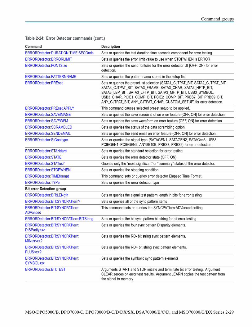
Table 2-24: Error Detector commands
Command Description
General purpose group
ERRORDetector:ALERT Sets or queries the audible alert setting {OFF, ON} for error detection.
ERRORDetector:ALIGNPRIMitive:MINus<x>?
This command queries the align primitive minus value.
ERRORDetector:ALIGNPRIMitive:PLUS<x>? This command queries the align primitive plus value.
ERRORDetector:BITRate Sets or queries the bit rate enumerated value {CUSTOM, RATE312, RATE1250,RATE1500, RATE2125, RATE2500, RATE3000, RATE3125, RATE4250,RATE5000, RATE6000, RATE6250} for error detection
ERRORDetector:BITRate:VALue Sets or queries the custom bitrate value {200000000..350000000, 1.25e9..6.25e9}for error detection. Some inetermediate values not supported. See data sheet.
ERRORDetector:CHANnel Sets or queries the channel source {CH1..CH4} for error detection.
ERRORDetector:DURATION:COUNt Sets or queries the test duration count as number of bits, frames, symbols, orcharacters to be tested for error testing
ERRORDetector:DURATION:SECOnds Sets or queries the test duration in seconds for error testing
ERRORDetector:DURATION:TIME Sets or queries the test duration time in days, hours, minutes, and seconds forerror detector
ERRORDetector:DURATION:TIME:DAYS Sets or queries the test duration time days component for error testing
ERRORDetector:DURATION:TIME:HOURS Sets or queries the test duration time hours component for error testing
ERRORDetector:DURATION:TIME:MINUTES Sets or queries the test duration time minutes component for error testing
2-28 MSO/DPO5000/B, DPO7000/C, DPO70000/B/C/D/DX/SX, DSA70000/B/C/D, and MSO70000/C/DX Series
Command groups
Table 2-24: Error Detector commands (cont.)
Command Description
ERRORDetector:DURATION:TIME:SECOnds Sets or queries the test duration time seconds component for error testing
ERRORDetector:ERRORLIMIT Sets or queries the error limit value to use when STOPWHEN is ERROR
ERRORDetector:FONTSIze Sets or queries the send fontsize for the error detector UI {OFF, ON} for errordetection.
ERRORDetector:PATTERNNAME Sets or queries the pattern name stored in the setup file.
ERRORDetector:PREset Sets or queries the preset list selection {SATA1_CJTPAT_BIT, SATA2_CJTPAT_BIT,SATA3_CJTPAT_BIT, SATA3_FRAME, SATA3_CHAR, SATA3_HFTP_BIT,SATA3_LBP_BIT, SATA3_LFTP_BIT, SATA3_MFTP_BIT, USB3_SYMBOL,USB3_CHAR, PCIE1_COMP_BIT, PCIE2_COMP_BIT, PRBS7_BIT, PRBS9_BIT,ANY_CJTPAT_BIT, ANY_CJTPAT_CHAR, CUSTOM_SETUP} for error detection.
ERRORDetector:PREset:APPLY This command causes selected preset setup to be applied.
ERRORDetector:SAVEIMAGE Sets or queries the save screen shot on error feature {OFF, ON} for error detection.
ERRORDetector:SAVEWFM Sets or queries the save waveform on error feature {OFF, ON} for error detection.
ERRORDetector:SCRAMBLED Sets or queries the status of the data scrambling option
ERRORDetector:SENDEMAIL Sets or queries the send email on error feature {OFF, ON} for error detection.
ERRORDetector:SIGnaltype Sets or queries the signal type {SATAGEN1, SATAGEN2, SATAGen3, USB3,PCIEGEN1, PCIEGEN2, ANY8B10B, PRBS7, PRBS9} for error detection
ERRORDetector:STANdard Sets or queries the standard selection for error testing
ERRORDetector:STATE Sets or queries the error detector state {OFF, ON}.
ERRORDetector:STATus? Queries only the “most significant” or “summary” status of the error detector.
ERRORDetector:STOPWHEN Sets or queries the stopping condition
ERRORDetector:TIMEformat This command sets or queries error detector Elapsed Time Format.
ERRORDetector:TYPe Sets or queries the error detector type
Bit error Detection group
ERRORDetector:BIT:LENgth Sets or queries the signal test pattern length in bits for error testing
ERRORDetector:BIT:SYNCPATtern? Sets or queries all of the sync pattern items
ERRORDetector:BIT:SYNCPATtern:ADVanced
This command sets or queries the SYNCPATtern:ADVanced setting.
ERRORDetector:BIT:SYNCPATtern:BITString Sets or queries the bit sync pattern bit string for bit error testing
ERRORDetector:BIT:SYNCPATtern:DISParity<x>
Sets or queries the four sync pattern Disparity elements.
ERRORDetector:BIT:SYNCPATtern:MINus<x>?
Sets or queries the RD- bit string sync pattern elements.
ERRORDetector:BIT:SYNCPATtern:PLUS<x>?
Sets or queries the RD+ bit string sync pattern elements.
ERRORDetector:BIT:SYNCPATtern:SYMBOL<x>
Sets or queries the symbolic sync pattern elements
ERRORDetector:BIT:TEST Arguments START and STOP initiate and terminate bit error testing. ArgumentCLEAR zeroes bit error test results. Argument LEARN copies the test pattern fromthe signal to memory
MSO/DPO5000/B, DPO7000/C, DPO70000/B/C/D/DX/SX, DSA70000/B/C/D, and MSO70000/C/DX Series 2-29

Command groups
Table 2-24: Error Detector commands (cont.)
Command Description
ERRORDetector:BIT:TEST:COUNt? Queries the bit error count for bit error testing
ERRORDetector:BIT:TEST:DURATION? Queries the elapsed duration of symbols tested for bit error testing
ERRORDetector:BIT:TEST:MAXALIGNS? Queries the maximum consecutive SATA align primitives or USB skip order setsfor bit error testing
ERRORDetector:BIT:TEST:RATE? Queries the calculated symbol error rate for bit error testing
ERRORDetector:BIT:TEST:RESults? Queries all the results for bit error testing
ERRORDetector:BIT:TEST:SECOnds? Queries the elapsed time in seconds for bit error testing
ERRORDetector:BIT:TEST:STATUS? Queries all of the bit error test status bits
ERRORDetector:BIT:TEST:STATUS:LOCK? Queries the LOCK status for bit error testing
ERRORDetector:BIT:TEST:STATUS:MAX_AP?
Queries the MAX_AP status for bit error testing
ERRORDetector:BIT:TEST:STATUS:SIGNAL?
Queries the SIGNAL status for bit error testing
ERRORDetector:BIT:TEST:STATUS:START? Queries the START status for bit error testing
ERRORDetector:BIT:TEST:STATUS:SYNC? Queries the SYNC status for bit error testing
ERRORDetector:BIT:TEST:TIME? Queries the elapsed time (in days, hours, minutes, and seconds) for bit error testing
ERRORDetector:BIT:TEST:TIME:DAYS? Queries the elapsed time days component for bit error testing
ERRORDetector:BIT:TEST:TIME:HOURS? Queries the elapsed time hours component for bit error testing
ERRORDetector:BIT:TEST:TIME:MINUTES? Queries the elapsed time minutes component for bit error testing
ERRORDetector:BIT:TEST:TIME:SECOnds? Queries the elapsed time seconds component for bit error testing
ERRORDetector:SSC Sets or queries the status of the spread spectrum clock tracking option
Frame error detection group
ERRORDetector:FRAME? Queries all frame error settings, status, and results
ERRORDetector:FRAme:EOF Sets or queries the End of Frame for frame error testing
ERRORDetector:FRAme:INITIALCRCVALue Sets or queries the initial CRC value for frame error testing
ERRORDetector:FRAme:SOF Sets or queries the Start of Frame for frame error testing
ERRORDetector:FRAme:TEST Arguments START and STOP initiate and terminate frame error testing. ArgumentCLEAR zeroes the frame error results
ERRORDetector:FRAme:TEST:BADCHARS? Queries the illegal character count for frame error testing
ERRORDetector:FRAme:TEST:COUNt? Queries the test error count for frame error testing
ERRORDetector:FRAme:TEST:DISParity? Queries the disparity error count for frame error testing
ERRORDetector:FRAme:TEST:DURATION? Queries the elapsed duration (in number of frames) tested by the frame
ERRORDetector:FRAme:TEST:MAXALIGNS?
Queries the maximum consecutive aligns encountered for frame error testing
ERRORDetector:FRAme:TEST:RATE? Queries the calculated frame error rate for frame error testing
ERRORDetector:FRAme:TEST:RESults? Queries all the results for frame error testing
ERRORDetector:FRAme:TEST:SECOnds? Queries the elapsed duration in seconds for frame error testing
ERRORDetector:FRAme:TEST:STATUS? Queries all of the frame error status at once
2-30 MSO/DPO5000/B, DPO7000/C, DPO70000/B/C/D/DX/SX, DSA70000/B/C/D, and MSO70000/C/DX Series

Command groups
Table 2-24: Error Detector commands (cont.)
Command Description
ERRORDetector:FRAme:TEST:STATUS:LOCK?
Queries the LOCK status for the frame error test
ERRORDetector:FRAme:TEST:STATUS:MAX_AP?
Queries the MAX_AP status for the frame error test
ERRORDetector:FRAme:TEST:STATUS:SIGNAL?
Queries the SIGNAL status for the frame error test
ERRORDetector:FRAme:TEST:STATUS:START?
Queries the START status for frame error tests
ERRORDetector:FRAme:TEST:TIME? Queries the elapsed time (in days, hours, minutes, and seconds) for frame errortesting
ERRORDetector:FRAme:TEST:TIME:DAYS? Queries the elapsed time days component for frame error testing
ERRORDetector:FRAme:TEST:TIME:HOURS?
Queries the elapsed time hours component for frame error testing
ERRORDetector:FRAme:TEST:TIME:MINUTES?
Queries the elapsed time minutes component for frame error testing
ERRORDetector:FRAme:TEST:TIME:SECOnds?
Queries the elapsed time seconds component for frame error testing
Symbol error detection group
ERRORDetector:SYMBOL? Queries all symbol error settings, status, and results
ERRORDetector:SYMBOL:TEST Arguments START and STOP initiate and terminate symbol error testing. ArgumentCLEAR zeroes the symbol error results. Argument SYNC re-syncs the recoveredclock.
ERRORDetector:SYMBOL:TEST:BADCHARS?
Queries the illegal character count for symbol error testing
ERRORDetector:SYMBOL:TEST:BITCOUNT?
Queries the bit error count (number of bad bits) for symbol error testing
ERRORDetector:SYMBOL:TEST:BITDURATION?
Queries the elapsed duration (in units of bits) tested for symbol error testing
ERRORDetector:SYMBOL:TEST:BITRate? Queries the calculated bit error rate for symbol error testing
ERRORDetector:SYMBOL:TEST:COUNt? Queries the symbol error count for symbol error testing
ERRORDetector:SYMBOL:TEST:DISParity? Queries the disparity error count for symbol error testing
ERRORDetector:SYMBOL:TEST:DURATION?
Queries the elapsed duration for symbol error testing
ERRORDetector:SYMBOL:TEST:MAXALIGNS?
Queries the maximum consecutive skip order sets encountered for symbol errortesting
ERRORDetector:SYMBOL:TEST:RATE? Queries the calculated symbol error rate for symbol error testing
ERRORDetector:SYMBOL:TEST:RESults? Queries all of the results for symbol error testing
ERRORDetector:SYMBOL:TEST:SECOnds? Queries the elapsed duration time in seconds for symbol error testing
ERRORDetector:SYMBOL:TEST:STATUS? Queries all of the status for the symbol error tests
ERRORDetector:SYMBOL:TEST:STATUS:LOCK?
Queries the LOCK status for the symbol error test
MSO/DPO5000/B, DPO7000/C, DPO70000/B/C/D/DX/SX, DSA70000/B/C/D, and MSO70000/C/DX Series 2-31

Command groups
Table 2-24: Error Detector commands (cont.)
Command Description
ERRORDetector:SYMBOL:TEST:STATUS:MAX_AP?
Queries the MAX_AP status for the symbol error test
ERRORDetector:SYMBOL:TEST:STATUS:SIGNAL?
Queries the SIGNAL status for the symbol error test
ERRORDetector:SYMBOL:TEST:STATUS:START?
Queries the START status for symbol error testing
ERRORDetector:SYMBOL:TEST:TIME? Queries the elapsed time (in days, hours, minutes, and seconds) for symbol errortesting
ERRORDetector:SYMBOL:TEST:TIME:DAYS?
Queries the elapsed time days component for symbol error testing
ERRORDetector:SYMBOL:TEST:TIME:HOURS?
Queries the elapsed time hours component for symbol error testing
ERRORDetector:SYMBOL:TEST:TIME:MINUTES?
Queries the elapsed time minutes component for symbol error testing
ERRORDetector:SYMBOL:TEST:TIME:SECOnds?
Queries the elapsed time seconds component for symbol error testing
Character error detection group
ERRORDetector:CHARacter? Queries all character error settings, status, and results
ERRORDetector:CHARacter:TEST Argument START and STOP initiate and terminate character error testing.Argument CLEAR zeroes the character error results
ERRORDetector:CHARacter:TEST:COUNt? Queries the number of illegal characters in the signal for error testing
ERRORDetector:CHARacter:TEST:DISPCOUNT?
Queries the number of disparity errors in the signal for character error testing
ERRORDetector:CHARacter:TEST:DISPRATE?
Queries the calculated disparity error rate for character error testing
ERRORDetector:CHARacter:TEST:DURATION?
Queries the elapsed duration in units of characters tested
ERRORDetector:CHARacter:TEST:MAXALIGNS?
Queries the maximum consecutive aligns encountered for character error testing
ERRORDetector:CHARacter:TEST:RATE? Queries the calculated illegal character error rate for error testing
ERRORDetector:CHARacter:TEST:RESults? Queries all of the character error test results
ERRORDetector:CHARacter:TEST:SECOnds?
Queries the elapsed duration time seconds component for character error testing
ERRORDetector:CHARacter:TEST:STATUS? Queries all of the status for character error tests
ERRORDetector:CHARacter:TEST:STATUS:LOCK?
Queries the LOCK status for the character error test
ERRORDetector:CHARacter:TEST:STATUS:MAX_AP?
Queries the MAX_AP status for the character error test
ERRORDetector:CHARacter:TEST:STATUS:SIGNAL?
Queries the SIGNAL status for the character error test
2-32 MSO/DPO5000/B, DPO7000/C, DPO70000/B/C/D/DX/SX, DSA70000/B/C/D, and MSO70000/C/DX Series

Command groups
Table 2-24: Error Detector commands (cont.)
Command Description
ERRORDetector:CHARacter:TEST:STATUS:START?
Queries the START status for the character error testing
ERRORDetector:CHARacter:TEST:TIME? Queries the elapsed time (in days, hours, minutes, and seconds) for charactererror testing
ERRORDetector:CHARacter:TEST:TIME:DAYS?
Queries the elapsed time days component for character error testing
ERRORDetector:CHARacter:TEST:TIME:HOURS?
Queries the elapsed time hours component for character error testing
ERRORDetector:CHARacter:TEST:TIME:MINUTES?
Queries the elapsed time minutes component for character error testing
ERRORDetector:CHARacter:TEST:TIME:SECOnds?
Queries the elapsed time seconds component for character error testing
File group
ERRORDetector:FILE:RECAll Initiates a file recall of error detector parameters from a text file
ERRORDetector:FILE:SAVe Initiates a file save of error detector parameters to a text file
Align pattern group
ERRORDetector:ALIGNCHARacter? Queries both of the align character values
ERRORDetector:ALIGNCHARacter:MINus? Sets or queries the RD- align character value
ERRORDetector:ALIGNCHARacter:PLUS? Sets or queries the RD+ align character value
ERRORDetector:ALIGNCHARacter:SYMBOL Sets or queries the Symbolic align character
ERRORDetector:ALIGNPRIMitive? Queries all of the align primitive values
ERRORDetector:ALIGNPRIMitive:MINUS? Queries the RD- align primitive enable and string values
ERRORDetector:ALIGNPRIMitive:PLUS? Queries the RD+ align primitive enable and string values
ERRORDetector:ALIGNPRIMitive:STATE Sets or queries the align primitive enable
ERRORDetector:ALIGNPRIMitive:SYMBOL<x>
Sets or queries the align primitive symbolic values
ERRORDetector:MAXALIGNS Sets or queries the maximum consecutive align primitives before an error
Skip order set group
ERRORDetector:SKIPSETPRIMitive:MINus<x>?
Queries the RD- skip order set array of bit string values.
ERRORDetector:SKIPSETPRIMitive:PLUS<x>?
This command queries the skip order RD+ array of bit string values.
ERRORDetector:SKIPSETPRIMitive:STATE Sets or queries the status of the RD+ skip order set option
ERRORDetector:SKIPSETPRIMitive:SYMBOL<x>
Sets or queries the symbolicc skip order set values
MSO/DPO5000/B, DPO7000/C, DPO70000/B/C/D/DX/SX, DSA70000/B/C/D, and MSO70000/C/DX Series 2-33

Command groups
File system command groupUse the commands in the File System Command Group to help you use thebuilt-in hard disk drive. You can use the commands to do the following:
List the contents of the default directory
Create and delete directories
Create, copy, read, rename, or delete a file
When using these commands, keep the following points in mind:
File arguments are always enclosed within double quotes:“C:\MYDIR\TEK00001.SET”
File names follow the MS-DOS format: [DRIVE:][\PATH\]filename
Path separators can be either forward slashes (/) or back slashes (\)
NOTE. Using a back slash as a path separator can produce some unexpectedresults, depending on how your controller application treats escaped characters.Many applications recognize the sequence of a back slash followed by analphabetic character as an escaped character, and, as such, interpret thatalphabetic character as a control character. For example, the sequence “\n”might be interpreted as a newline character; “\t” might be interpreted as a tabcharacter. To ensure that this interpretation does not occur, you can use doubleback slashes. For example, “C:\\testfile.txt”.
Some FILESystem commands can fail because a file has read-only attributes.You will not be able to delete or replace such files until this attribute isremoved. Refer to the operating system help on file properties for furtherinformation.
Table 2-25: File system commands
Command Description
FILESystem? Returns the file system state
FILESystem:COPy Copies one or more files to a new file
FILESystem:CWD Sets or queries the current working directory for FILESystem GPIB commands
FILESystem:DELEte Deletes a named file or directory
FILESystem:DIR? Returns a list of directory contents
FILESystem:MKDir Makes a new directory
FILESystem:PRInt Prints a named file to the named port
FILESystem:READFile Copies the named file to the GPIB port
FILESystem:REName Assigns a new name to an existing file
FILESystem:RMDir Deletes the named directory
FILESystem:WRITEFile Copies the GPIB port block data to a named file
2-34 MSO/DPO5000/B, DPO7000/C, DPO70000/B/C/D/DX/SX, DSA70000/B/C/D, and MSO70000/C/DX Series

Command groups
Hard copy command groupHard Copy commands enable you to make hard copies of data files or send thedata to a specified file. In addition, these commands provide you with informationabout (and the ability to set) file path settings.
Table 2-26: Hard copy commands
Command Description
EXPort Copies a waveform to a specified file or returns formatting and file information
EXPort:FILEName Sets or queries the export file path
EXPort:FORMat Sets or queries the export image format
EXPort:PALEtte Sets or queries the export color palette
EXPort:READOuts Sets or queries the position of the readouts for export
EXPort:VIEW Sets or queries the export screen capture area
HARDCopy Sends a screen copy to the selected port or returns the selected port and file path
HARDCopy:FILEName Sets or queries the hard copy file path
HARDCopy:LAYout Sets or queries the page orientation for hard copy
HARDCopy:PALEtte Sets or queries the hard copy color palette
HARDCopy:PORT Sets or queries whether the hard copy data will be sent to a file or printed on thenext hard copy command
HARDCopy:READOuts Sets or queries the position of the readouts for hardcopy
HARDCopy:VIEW Sets or queries the area of the screen to be hardcopied
MSO/DPO5000/B, DPO7000/C, DPO70000/B/C/D/DX/SX, DSA70000/B/C/D, and MSO70000/C/DX Series 2-35

Command groups
Histogram command groupHistogram commands let you select the type of histogram, specify what part ofthe waveform should go into the histogram, and retrieve histogram statistics. Usecommands from this group to do the following:
Create a histogram of vertical or horizontal values for a channel, math, orreference waveform
Adjust the limits of the waveform area from which the histogram data isobtained
Clear histogram count and restart
Retrieve the histogram data
Table 2-27: Histogram commands
Command Description
HIStogram? Returns all histogram parameters
HIStogram:BOX Sets or queries the left, top, right, and bottom positions of the histogram box, insource waveform coordinates
HIStogram:BOXPcnt Sets or queries same as HIStogram:BOX, but in percentage coordinates, with0,0 upper left and 100,100 lower right
HIStogram:COUNt Clears histogram count source data and restarts counting
HIStogram:DATa? Returns a comma-separated list of histogram data numbers
HIStogram:DISplay Sets or queries whether histogram data is displayed and the current display typesetting
HIStogram:FUNCtion Sets the type of histogram to create
Or queries the current histogram type
HIStogram:MODe Sets type of histogram to create or turns histograms off
Or queries the current histogram type or that histogram display is disabled
HIStogram:SIZe Sets or queries the width (or height) of the histogram on the screen in divisions
HIStogram:SOUrce Sets or queries which source waveform will be compared against the histogram boxwhen the histogram testing is enabled
HIStogram:STATE Sets or queries whether histogram calculations are enabled
2-36 MSO/DPO5000/B, DPO7000/C, DPO70000/B/C/D/DX/SX, DSA70000/B/C/D, and MSO70000/C/DX Series

Command groups
Horizontal command groupHorizontal commands control the time bases of the instrument. You can set thetime per division (or time per point) of the main time base. You can use theHorizontal commands to do the following:
Set the scale, horizontal position and reference, and units of the time base
Get the screen resolution, time of first point and time of last point, or get allthe horizontal settings
Enable or disable the display of the time base
You can substitute SECdiv for SCAle in the horizontal commands. This providesprogram compatibility with earlier models of Tektronix instruments.
Table 2-28: Horizontal commands
Command Description
HORizontal? Returns all learnable settings for the horizontal commands
HORizontal:ACQDURATION? Returns the time base duration
HORizontal:ACQLENGTH? Returns the record length
HORizontal:DIGital:MAGnivu:POSition? Queries the horizontal position of the MagniVu digital acquisition
NOTE. Not available on some modelsHORizontal:DIGital:RECOrdlength? Queries the record length of the digital acquisition
HORizontal:DIGital:RECOrdlength:MAGnivu? Queries the record length of the MagniVu digital acquisition
NOTE. Not available on some modelsHORizontal:DIGital:RECOrdlength:MAIn? Queries the record length of the main digital acquisition
HORizontal:DIGital:SAMPLERate? Queries the sample rate of the digital acquisition
HORizontal:DIGital:SAMPLERate:MAGnivu? Queries the sample rate of the MagniVu digital acquisition
NOTE. Not available on some modelsHORizontal:DIGital:SAMPLERate:MAIn? Queries the sample rate of the main digital acquisition
HORizontal:DIVisions? Returns the number of graticule divisions over which the waveform is displayed
HORizontal:FASTframe? Returns all settings for the horizontal FastFrame commands
HORizontal:FASTframe:COUNt Sets or queries the FastFrame frame count
HORizontal:FASTframe:MAXFRames? Returns the maximum number of FastFrame frames which can be acquired atthe current frame length
HORizontal:FASTframe:MULtipleframes:FRAMESTart:<wfm>
Sets or queries the start frame number on the specified waveform for FastFramemultiple frames
HORizontal:FASTframe:MULtipleframes:MODe
Sets or queries the mode for FastFrame multiple frames
HORizontal:FASTframe:MULtipleframes:NUMFRames:<wfm>
Sets or queries the number of frames on the specified waveform for FastFramemultiple frames
HORizontal:FASTframe:REF:FRAme Sets or queries the FastFrame reference frame number
HORizontal:FASTframe:REF:SOUrce Sets or queries the FastFrame Reference waveform source
MSO/DPO5000/B, DPO7000/C, DPO70000/B/C/D/DX/SX, DSA70000/B/C/D, and MSO70000/C/DX Series 2-37

Command groups
Table 2-28: Horizontal commands (cont.)
Command Description
HORizontal:FASTframe:SELECTED:CH<x> Sets or queries the FastFrame selected frame number on the specified waveform
HORizontal:FASTframe:SELECTED:MATH<x>
Sets or queries the FastFrame selected frame number on the specified waveform
HORizontal:FASTframe:SELECTED:REF<x> Sets or queries the FastFrame selected frame number on the specified waveform
HORizontal:FASTframe:SELECTED:SOUrce Sets or queries the FastFrame source waveform
HORizontal:FASTframe:SEQuence Sets or queries the FastFrame source waveform
HORizontal:FASTframe:SINGLEFramemath Sets or queries FastFrame single frame math
HORizontal:FASTframe:SIXteenbit Sets or queries FastFrame sixteen bit
HORizontal:FASTframe:STATE Sets or queries the state of FastFrame acquisition
HORizontal:FASTframe:SUMFrame Sets or queries the summary frame mode
HORizontal:FASTframe:TIMEStamp:ALL:<wfm>?
Returns the frame number and time stamp for each frame between requestedframes, inclusive, within the specified waveform
HORizontal:FASTframe:TIMEStamp:BETWeen:<wfm>?
Returns the relative trigger for the delta time between the specified frames, withinthe specified waveform
HORizontal:FASTframe:TIMEStamp:DELTa:<wfm>?
Returns the relative time between the triggers of the FastFrame Selected and theFastFrame Reference, within the specified waveform
HORizontal:FASTframe:TIMEStamp:FRAMe:<wfm>?
Returns the absolute trigger date and time for the specified frame and waveform
HORizontal:FASTframe:TIMEStamp:REF? Returns the absolute trigger date and time for the FastFrame specified referencewaveform
HORizontal:FASTframe:TIMEStamp:SELECTED:<wfm>?
Returns the absolute trigger date and time for the FastFrame Selected, within thespecified waveform
HORizontal:FASTframe:TRACk Sets up or returns the state of FastFrame tracking
HORizontal:FASTframe:XZEro:ALL:CH<x>? Returns the time from the trigger to the start of the specified frames on the specifiedchannel
HORizontal:FASTframe:XZEro:ALL:REF<x>? Returns the time from the trigger to the start of the specified frames on the specifiedreference
HORizontal:FASTframe:XZEro:FRAme:CH<x>?
Returns the time from the trigger to the start of the specified frame on the specifiedchannel
HORizontal:FASTframe:XZEro:FRAme:REF<x>?
Returns the time from the trigger to the start of the specified frame on the specifiedreference
HORizontal:FASTframe:XZEro:REF? Sets or queries the time from the trigger to the trigger sample on the referencewaveform
HORizontal:FASTframe:XZEro:SELECTED:CH<x>?
Sets or queries the time from the trigger to the trigger sample on the selectedchannel
HORizontal:FASTframe:XZEro:SELECTED:REF<x>?
Sets or queries the time from the trigger to the trigger sample on the selectedreference waveform
HORizontal:MAIn? Returns the time per division of the main time base
HORizontal[:MAIn]:DELay:MODe Sets or queries the main time base trigger delay mode
2-38 MSO/DPO5000/B, DPO7000/C, DPO70000/B/C/D/DX/SX, DSA70000/B/C/D, and MSO70000/C/DX Series

Command groups
Table 2-28: Horizontal commands (cont.)
Command Description
HORizontal[:MAIn]:DELay:POSition Sets or queries the main time base position when Horizontal Delay Mode is turnedoff
HORizontal[:MAIn]:DELay:TIMe Sets or queries the main time base trigger delay time
HORizontal:MAIn:INTERPRatio? Returns the main horizontal time base interpolation ratio
HORizontal[:MAIn]:POSition Sets or queries the waveform horizontal position on the display
HORizontal:MAIn:UNIts Sets or queries the units for the horizontal time base
HORizontal:MAIn:UNIts:STRing Sets or queries the units string for the horizontal main time base trigger delay
HORizontal:MODE Sets or queries the horizontal mode. Auto mode is the factory default
HORizontal:MODE:AUTO:LIMITrecordlen Sets or queries the record length limit used by the auto horizontal mode
HORizontal:MODE:RECOrdlength Sets or queries the record length
HORizontal:MODE:SAMPLERate Sets or queries the sample rate
HORizontal:MODE:SCAle Sets or queries the horizontal scale
HORizontal:POSition Either positions the waveform horizontally on the display or returns its horizontalposition on the display
HORizontal:ROLL Sets or queries the horizontal roll mode status
HORizontal:TIMEStamp:CH<x>? Returns the absolute trigger date and time for the specified frame and waveform
HORizontal:TIMEStamp:REF<x>? Returns the absolute trigger date and time for FastFrame reference
MSO/DPO5000/B, DPO7000/C, DPO70000/B/C/D/DX/SX, DSA70000/B/C/D, and MSO70000/C/DX Series 2-39

Command groups
Limit Test command groupUse the commands in the Limit Test Command Group to perform limit testingby selecting channel, math, or reference waveforms and comparing them againsta template waveform.
Table 2-29: Limit Test commands
Command Description
LIMit? Returns all settings for the Limit commands
LIMit:BEEP Causes the instrument to beep when the waveform data exceeds the limits set inthe limit test
LIMit:COMpare Resets the limit test comparison template
LIMit:COMpare:CH<x> Sets or queries the template against which to compare the waveform acquiredfrom the channel specified by x
LIMit:COMpare:MATH<x> Sets or queries the template against which to compare the math waveform specifiedby x
LIMit:COMpare:REF<x> Sets or queries the template against which to compare the reference waveformspecified by x
LIMit:EMail Sets or queries whether an E-mail is generated when the source waveform dataexceeds the limits specified for the limit test
LIMit:HARDCopy Sets or queries whether a hard copy operation is executed on the waveform whenany waveform data exceeds the limit set in the limit test. LIMit:STATE must be set toON for the hard copy operation to execute
LIMit:HIGHLIGHTHits Sets or queries whether violation highlighting occurs when limit testing is active,and, if the RESET argument is set, clears the highlighting
LIMit:HIGHLIGHTHits:RESet Resets the hits highlighting for limit testing
LIMit:LOCk Sets or queries whether vertical scaling and positioning affect both source andtemplate for template comparison pairs
LIMit:LOG Sets or queries whether a log file is saved when the source waveform data exceedsthe test limits
LIMit:SAVEWFM Sets or queries whether the source waveform is saved when the source waveformdata exceeds the test limits
LIMit:SAVEWFM:FILEName Sets or queries the path where waveforms or log files will be saved when thewaveform data exceeds the limits set by the limit test
LIMit:SRQ Sets or queries whether a Service Request Interrupt (SRQ) is generated when thewaveform data falls outside of the test limits
LIMit:STATE Sets limit testing on or off or queries whether limit testing is in effect
LIMit:STATus? Queries the state of limit testing
LIMit:STOPOnviolation Sets or queries whether acquisitions are stopped when the waveform data exceedsthe test limits
LIMit:TEMPlate:STORe Saves the specified source waveform to the specified reference or file name
LIMit:TEMPlate:TOLerance:HORizontal Sets or queries the amount in units of horizontal divisions, by which the sourcewaveform is varied horizontally when creating the destination waveform
2-40 MSO/DPO5000/B, DPO7000/C, DPO70000/B/C/D/DX/SX, DSA70000/B/C/D, and MSO70000/C/DX Series

Command groups
Table 2-29: Limit Test commands (cont.)
Command Description
LIMit:TEMPlate:TOLerance:VERTical Sets or queries the amount in units of vertical divisions, by which the sourcewaveform is varied vertically when creating the destination waveform
LIMit:TEMPlate:DESTination Sets or queries destination reference waveform that the limit template destinationcommand will use
LIMit:TEMPlate:SOUrce Sets or queries the channel, math waveform, or reference waveform that theLIMit:TEMPlate:STORe command will use
Link Training command groupUse these commands to control link training on the instrument.
Table 2-30:
Command Description
LINKTRaining:ARMscope Sets or queries the ARMscope setting of Link Training.
LINKTRaining:DECOde Sets or queries the Decode setting of the Link Training.
LINKTRaining:LANE Sets or queries the activation of the individual communications lanes under test.
LINKTRaining:MARK Sets or queries the Mark setting of the Link Training application.
LINKTRaining:STANdard Sets or queries the communication standard for Link Training.
LINKTRaining:TRIGgeron Sets or queries the TriggerOn setting of Link Training.
LINKTRaining:STAte Sets or queries the state of the Link Training application.
MSO/DPO5000/B, DPO7000/C, DPO70000/B/C/D/DX/SX, DSA70000/B/C/D, and MSO70000/C/DX Series 2-41

Command groups
Low Speed Serial Trigger command groupUse the commands in the Low Speed Serial Trigger Command Group to controlserial triggering for the instrument.
NOTE. CAN, FlexRay, I2C, LIN, MIPI, PCIE, RS-232, SPI, USB, and 8B10Btrigger commands are optional.
Table 2-31: Low Speed Serial Trigger commands
Command Description
TRIGger:A:BUS:CAN:CONDition Sets or queries the CAN bus trigger condition
TRIGger:A:BUS:CAN:DATa:DIRection Sets or queries the CAN bus trigger data direction
TRIGger:A:BUS:CAN:DATa:FORMat Sets or queries the CAN bus trigger data format
TRIGger:A:BUS:CAN:DATa:QUALifier Sets or queries CAN bus trigger data qualifier
TRIGger:A:BUS:CAN:DATa:SIZe Sets or queries the CAN bus trigger data size
TRIGger:A:BUS:CAN:DATa:VALue Sets or queries CAN bus trigger data value
TRIGger:A:BUS:CAN:FRAMEtype Sets or queries CAN bus trigger frame type
TRIGger:A:BUS:CAN{:IDentifier|:ADDRess}:DIRection
Sets or queries the CAN bus trigger identifier direction
TRIGger:A:BUS:CAN{:IDentifier|:ADDRess}:FORMat
Sets or queries the CAN bus identifier format
TRIGger:A:BUS:CAN{:IDentifier|:ADDRess}:MODe
Sets or queries CAN bus trigger identifier mode
TRIGger:A:BUS:CAN{:IDentifier|:ADDRess}:VALue
Sets or queries the CAN bus trigger identifier value
TRIGger:A:BUS:DATa:FORMat Sets or queries the trigger data format for the bus
TRIGger:A:BUS:DATa:VALue Sets or queries the trigger data value depending on the format selected for the bus
TRIGger:A:BUS:FLEXRAY:CONDition Sets or queries the FLEXRAY bus trigger condition
TRIGger:A:BUS:FLEXRAY:CYCLEcount:FORMat
Sets or queries FLEXRAY bus trigger cycle count format
TRIGger:A:BUS:FLEXRAY:CYCLEcount:QUALifier
Sets or queries FLEXRAY bus trigger cycle count qualifier
TRIGger:A:BUS:FLEXRAY:CYCLEcount:VALue
Sets or queries the FLEXRAY bus trigger cycle count value
TRIGger:A:BUS:FLEXRAY:DATa:FORMat Sets or queries the FLEXRAY bus trigger data format
TRIGger:A:BUS:FLEXRAY:DATa:OFFSet Sets or queries the FLEXRAY bus trigger data offset
TRIGger:A:BUS:FLEXRAY:DATa:QUALifier Sets or queries the FLEXRAY bus trigger data qualifier
TRIGger:A:BUS:FLEXRAY:DATa:SIZe Sets or queries the FLEXRAY bus trigger data size
TRIGger:A:BUS:FLEXRAY:DATa:VALue Sets or queries the FLEXRAY bus trigger data value
TRIGger:A:BUS:FLEXRAY:EOFTYPE Sets or queries the FLEXRAY bus end of file type
TRIGger:A:BUS:FLEXRAY:ERRTYPE Sets or queries the FLEXRAY bus trigger error type
2-42 MSO/DPO5000/B, DPO7000/C, DPO70000/B/C/D/DX/SX, DSA70000/B/C/D, and MSO70000/C/DX Series

Command groups
Table 2-31: Low Speed Serial Trigger commands (cont.)
Command Description
TRIGger:A:BUS:FLEXRAY:FRAMEType Sets or queries the FLEXRAY bus trigger frame type
TRIGger:A:BUS:FLEXRAY:HEADER:CRC Sets or queries the FLEXRAY bus trigger header CRC
TRIGger:A:BUS:FLEXRAY:HEADER:CYCLECount
Sets or queries the FLEXRAY bus trigger header cycle count
TRIGger:A:BUS:FLEXRAY:HEADER:FRAMEID
Sets or queries the FLEXRAY bus trigger header frame ID
TRIGger:A:BUS:FLEXRAY:HEADER:INDBits Sets or queries the FLEXRAY bus trigger header Indicator Bits
TRIGger:A:BUS:FLEXRAY:HEADER:PAYLENgth
Sets or queries the FLEXRAY bus trigger header Payload Length
TRIGger:A:BUS:FLEXRAY:IDentifier:FORMat Sets or queries the FLEXRAY bus trigger identifier format
TRIGger:A:BUS:FLEXRAY:IDentifier:QUALifier
Sets or queries the FLEXRAY bus trigger identifier qualifier
TRIGger:A:BUS:FLEXRAY:IDentifier:VALue Sets or queries the FLEXRAY bus trigger identifier value
TRIGger:A:BUS:I2C:ADDress:FORMat Sets or queries the address format for the I2C bus
TRIGger:A:BUS:I2C:ADDress:MODe Sets or queries the address mode for the I2C bus
TRIGger:A:BUS:I2C:ADDress:TYPe Sets or queries the address type for the I2C bus trigger
TRIGger:A:BUS:I2C:ADDress:VALue Sets or queries the binary address string used for the I2C trigger of the bus
TRIGger:A:BUS:I2C:CONDition Sets or queries the trigger condition for the I2C bus
TRIGger:A:BUS:I2C:DATa:DIRection Sets or queries the data direction for the I2C bus
TRIGger:A:BUS:I2C:DATa:FORMat Sets or queries the trigger data format for the I2C bus
TRIGger:A:BUS:I2C:DATa:SIZe Sets or queries the length of the data string in bytes to be used for an I2C trigger
TRIGger:A:BUS:I2C:DATa:VALue Sets or queries the data value of the data token for an I2C trigger
TRIGger:A:BUS:LIN:CONDition Sets or queries the LIN bus trigger condition
TRIGger:A:BUS:LIN:DATa:FORMat Sets or queries the LIN bus trigger data format
TRIGger:A:BUS:LIN:DATa:QUALifier Sets or queries the LIN bus trigger data qualifier
TRIGger:A:BUS:LIN:DATa:SIZe Sets or queries the LIN bus trigger data size
TRIGger:A:BUS:LIN:DATa:VALue Sets or queries the LIN bus trigger data value
TRIGger:A:BUS:LIN:ERRTYPE Sets or queries the LIN bus trigger error type
TRIGger:A:BUS:LIN:IDentifier:FORMat Sets or queries the LIN bus trigger identifier format
TRIGger:A:BUS:LIN:IDentifier:VALue Sets or queries the LIN trigger identifier value
TRIGger:A:BUS:PCIE:CHARacter:CHAR Sets or queries the PCIE bus trigger character
TRIGger:A:BUS:PCIE:CHARacter:SYMbol:MINus
Sets or queries the PCIE bus trigger character symbol minus
TRIGger:A:BUS:PCIE:CHARacter:SYMbol:PLUS
sets or queries PCIE bus trigger character symbol plus
TRIGger:A:BUS:PCIE:CONDition Sets or queries the PCIE bus trigger condition
TRIGger:A:BUS:PCIE:DISParity Sets or queries the PCIE bus trigger disparity
TRIGger:A:BUS:PCIE:ERROR Sets or queries the PCIE bus trigger error
MSO/DPO5000/B, DPO7000/C, DPO70000/B/C/D/DX/SX, DSA70000/B/C/D, and MSO70000/C/DX Series 2-43

Command groups
Table 2-31: Low Speed Serial Trigger commands (cont.)
Command Description
TRIGger:A:BUS:PCIE:FORMat Sets or queries the PCIe bus trigger format
TRIGger:A:BUS:PCIE:PATtern:CHAR<x> Sets or queries the PCIE bus trigger pattern character
TRIGger:A:BUS:PCIE:PATtern:ORDERedset Sets or queries the PCIE bus trigger pattern ordered set
TRIGger:A:BUS:PCIE:PATtern:SYMbol:MINus<x>
Sets or queries the PCIE bus trigger pattern symbol minus
TRIGger:A:BUS:PCIE:PATtern:SYMbol:PLUS<x>
Sets or queries the PCIE bus trigger pattern plus symbol
TRIGger:A:BUS:RS232C:CONDition Sets or queries the trigger condition for the specified RS232 bus
TRIGger:A:BUS:RS232C:DATa:FORMat Sets or queries the data format for the RS232c bus trigger
TRIGger:A:BUS:RS232C:DATa:SIZe Sets or queries the length of the data string in bytes to be used for an RS232 trigger
TRIGger:A:BUS:RS232C:DATa:VALue Sets or queries the data value of the data token for an RS232 trigger
TRIGger:A:BUS:SOUrce Sets or queries the source for a bus trigger
TRIGger:A:BUS:SPI:CONDition Sets or queries the trigger condition for the SPI bus
TRIGger:A:BUS:SPI:DATa:FORMat Sets or queries the format of the data to be used for an SPI trigger when the triggercondition is Data
TRIGger:A:BUS:SPI:DATa:SIZe Sets or queries the length of the data string in bytes to be used for an SPI trigger
TRIGger:A:BUS:SPI:DATa:VALue Sets or queries the data value of the data token for an SPI trigger
TRIGger:A:BUS:USB:ADDress:FORMat Sets or queries the address format for the USB bus trigger normal token
TRIGger:A:BUS:USB:ADDress:HIVALue Sets address value for normal token to be used with In Range and Out of Rangequalifiers
TRIGger:A:BUS:USB:ADDress:VALue Sets address value for normal token
TRIGger:A:BUS:USB:CHARacter:CHAR Sets or queries the USB character when the Trigger Condition is set to Character.
TRIGger:A:BUS:USB:CHARacter:SYMbol:MINus
Sets or queries the character bit pattern (negative disparity) when the TriggerCondition is set to Character.
TRIGger:A:BUS:USB:CHARacter:SYMbol:PLUS
Sets or queries the Character bit pattern (positive disparity view) when the TriggerCondition is set to Character.
TRIGger:A:BUS:USB:CONDition Sets or queries the trigger condition for the specified USB bus
TRIGger:A:BUS:USB:DATa:FORMat Sets or queries the data format for the USB bus trigger
TRIGger:A:BUS:USB:DATa:HIVALue Sets or queries the trigger data value for data token of the specified USB bus
TRIGger:A:BUS:USB:DATa:OFFSet Sets or queries the data offset for the USB bus trigger
TRIGger:A:BUS:USB:DATa:SIZe Sets or queries the number of contiguous data bytes for the USB bus trigger
TRIGger:A:BUS:USB:DATa:TYPe Sets or queries the data packet type when USB bus trigger condition is Data Packet
TRIGger:A:BUS:USB:DATa:VALue Sets or queries the USB bus trigger data value for data token
TRIGger:A:BUS:USB:DISParity Sets or queries the type of disparity that the bus will trigger on.
TRIGger:A:BUS:USB:ENDPoint:FORMat Sets or queries the endpoint format for data token to be used with in range andout of range qualifiers
TRIGger:A:BUS:USB:ENDPoint:HIVALue Sets or queries the endpoint value for data token to be used with in range andout of range qualifiers
TRIGger:A:BUS:USB:ENDPoint:VALue Sets or queries the endpoint value for normal token of the specified USB bus
2-44 MSO/DPO5000/B, DPO7000/C, DPO70000/B/C/D/DX/SX, DSA70000/B/C/D, and MSO70000/C/DX Series

Command groups
Table 2-31: Low Speed Serial Trigger commands (cont.)
Command Description
TRIGger:A:BUS:USB:ERROR Sets or queries whether the oscilloscope will trigger on a character error or adisparity error.
TRIGger:A:BUS:USB:ERRTYPE Sets or queries the error type when USB bus trigger on condition is set to Error
TRIGger:A:BUS:USB:FORMat Sets or queries the pattern editing format.
TRIGger:A:BUS:USB:HANDShaketype Sets or queries the handshake type when USB bus trigger on condition is set toHandshake Packet
TRIGger:A:BUS:USB:PATtern:CHAR<x> Sets or queries the specified character when the Trigger Condition is set to Pattern.
TRIGger:A:BUS:USB:PATtern:ORDERedset Sets or queries the state of triggering on an ordered set.
TRIGger:A:BUS:USB:PATtern:SYMbol:MINus<x>
Sets or queries the specified character bit pattern (negative disparity) when theTrigger Condition is set to Pattern.
TRIGger:A:BUS:USB:PATtern:SYMbol:PLUS<x>
Sets or queries the specified character bit pattern (positive disparity) when theTrigger Condition is set to Pattern.
TRIGger:A:BUS:USB:QUAlifier Sets or queries the USB bus trigger qualifier for address, endpoint, and data
TRIGger:A:BUS:USB:SOF:FORMat Sets or queries the format for the SOF frame number
TRIGger:A:BUS:USB:SOF:FRAMENUMber Sets frame number for the USB bus trigger when the condition is Start Of Frame(SOF)
TRIGger:A:BUS:USB:SPECIALType Sets or queries the PID value for Special Packet USB bus trigger on condition
TRIGger:A:BUS:USB:SPLIT:ET:VALue Sets or queries the Endpoint Type value of the specified USB bus trigger
TRIGger:A:BUS:USB:SPLIT:HUB:FORMat Sets or queries the format for the hub address of the USB bus trigger on split tokenfield
TRIGger:A:BUS:USB:SPLIT:HUB:VALue Sets or queries the hub address for SPLIT token of the USB bus trigger
TRIGger:A:BUS:USB:SPLIT:PORT:FORMat Sets the port address format for the USB bus trigger on split token field
TRIGger:A:BUS:USB:SPLIT:PORT:VALue Sets or queries the port address for SPLIT token of the USB bus trigger
TRIGger:A:BUS:USB:SPLIT:SC:VALue Sets or queries the Start/Complete value for the USB bus trigger on split token field
TRIGger:A:BUS:USB:SPLIT:SE:VALue Sets or queries the Start/End value for the USB bus trigger
TRIGger:A:BUS:USB:TOKENType Sets or queries the Token Type when USB Trigger condition is set to Token(Address) Packet
DPO7000 Series only
TRIGger:A:CAN:CONDition Sets or queries the CAN condition
NOTE. This trigger is available only with Option LSA installedTRIGger:A:CAN:DATa:DIRection Sets or queries the CAN trigger condition to be valid on a READ, WRITE, or either
NOTE. This trigger is available only with Option LSA installedTRIGger:A:CAN:FORMat Sets or queries the CAN data format
NOTE. This trigger is available only with Option LSA installedTRIGger:A:CAN:DATa:LEVel Sets or queries the CAN Trigger threshold for the CAN data source
NOTE. This trigger is available only with Option LSA installed
MSO/DPO5000/B, DPO7000/C, DPO70000/B/C/D/DX/SX, DSA70000/B/C/D, and MSO70000/C/DX Series 2-45

Command groups
Table 2-31: Low Speed Serial Trigger commands (cont.)
Command Description
TRIGger:A:CAN:DATa:SOUrce Sets or queries the CAN data source
NOTE. This trigger is available only with Option LSA installedTRIGger:A:CAN:DATa:VALue Sets or queries the binary data string used for CAN Trigger if the trigger condition is
ID or IDANDDATA
NOTE. This trigger is available only with Option LSA installedTRIGger:A:CAN:FRAMEtype Sets or queries the CAN trigger frame type
NOTE. This trigger is available only with Option LSA installedTRIGger:A:CAN:IDENTifier:MODe Sets or queries the CAN trigger identifier mode
NOTE. This trigger is available only with Option LSA installedTRIGger:A:CAN:IDENTifier:VALue Sets or queries the binary address string used for the CAN trigger if the trigger
condition is ID or IDANDDATA
NOTE. This trigger is available only with Option LSA installedTRIGger:A:CAN:PROBE Sets or queries the probing method used to probe the CAN signal
NOTE. This trigger is available only with Option LSA installedTRIGger:A:CAN:SPEed Sets or queries the bit rate of the CAN system
NOTE. This trigger is available only with Option LSA installedTRIGger:A:I2C:ADDRess:MODe Sets or queries the I2C address mode to 7 or 10 bit
TRIGger:A:I2C:ADDRess:RWINClude Sets or queries the I2C address mode to include the read/write bit as an additional8th bit of the 7-bit address
TRIGger:A:I2C:ADDRess:TYPe Sets or queries the I2C address type
TRIGger:A:I2C:ADDRess:VALue Sets or queries the binary address string used for the I2C trigger if the triggercondition is ADDR or ADDRANDDATA
TRIGger:A:I2C:CLOCk:LEVel Sets or queries the clock source for the I2C Serial Trigger
TRIGger:A:I2C:CLOCk:SOUrce Sets or queries the clock source for the I2C Serial Trigger
TRIGger:A:I2C:CONDition Sets or queries the trigger condition for the I2C trigger
TRIGger:A:I2C:DATa:DIRection Sets or queries the I2C trigger condition valid on a READ, WRITE, or either
TRIGger:A:I2C:DATa:LEVel Sets or queries the threshold level for the I2C data source
TRIGger:A:I2C:DATa:SOUrce Sets or queries the data source for the I2C serial trigger
TRIGger:A:I2C:DATa:STARt Sets or queries the data start byte
TRIGger:A:I2C:DATa:VALue Sets or queries the binary data string used for I2C triggering if the trigger conditionis DATA or ADDRANDDATA
TRIGger:A:I2C:FORMat Sets or queries the display format for the I2C data value
TRIGger:A:RS232:BAUd Sets or queries the baud rate for RS232 triggering
TRIGger:A:RS232:DATa:LEVel Sets or queries the threshold for the RS232 data source
TRIGger:A:RS232:DATa:SOUrce Sets or queries the RS232 data source
TRIGger:A:RS232:DATa:VALue Sets or queries the binary data string used for RS232 triggering
2-46 MSO/DPO5000/B, DPO7000/C, DPO70000/B/C/D/DX/SX, DSA70000/B/C/D, and MSO70000/C/DX Series

Command groups
Table 2-31: Low Speed Serial Trigger commands (cont.)
Command Description
TRIGger:A:RS232:FORMat Sets or queries the display format for the RS232 data value
TRIGger:A:RS232:PARity Sets or queries the state of the RS232 parity bit
TRIGger:A:SPI:CONDition Sets or queries the trigger condition for SPI triggering
TRIGger:A:SPI:DATa:MISO:ACTIVE Sets or queries the SPI MISO polarity
TRIGger:A:SPI:DATa:MISO:LEVel Sets or queries the threshold for the SPI MISO data source
TRIGger:A:SPI:DATa:MISO:SOUrce Sets or queries the MISO data source for the SPI trigger
TRIGger:A:SPI:DATa:MISO:VALue Sets or queries the binary data string used for the SPI trigger if the trigger conditionis set to MISO or MISOMOSI
TRIGger:A:SPI:DATa:MOSI:ACTIVE Sets or queries the SPI MOSI polarity
TRIGger:A:SPI:DATa:MOSI:LEVel Sets or queries the threshold for the SPI MOSI data source
TRIGger:A:SPI:DATa:MOSI:SOUrce Sets or queries the MOSI data source for the SPI trigger
TRIGger:A:SPI:DATa:MOSI:VALue Sets or queries the binary data string used for the SPI trigger if the trigger conditionis set to MOSI or MISOMOSI
TRIGger:A:SPI:DATa:STARt Sets or queries the nth data byte on the data source after the signal on the enableslave source switches to the polarity specified by the Slave Select Polarity
TRIGger:A:SPI:FORMat Sets or queries the SPI trigger data format
TRIGger:A:SPI:SCLK:ACTIVE Sets or queries the SPI SCLK polarity
TRIGger:A:SPI:SCLK:LEVel Sets or queries the threshold for the SPI trigger SCLK
TRIGger:A:SPI:SCLK:SOUrce Sets or queries the SPI SCLK source
TRIGger:A:SPI:SS:ACTIVE Sets or queries the SPI trigger Slave Select (SS) polarity
TRIGger:A:SPI:SS:LEVel Sets or queries the threshold for the SPI trigger Slave Select (SS) signal
TRIGger:A:SPI:SS:SOUrce Sets or queries the SPI trigger Slave Select (SS) source
MSO/DPO5000/B, DPO7000/C, DPO70000/B/C/D/DX/SX, DSA70000/B/C/D, and MSO70000/C/DX Series 2-47

Command groups
Mask command groupMask commands compare incoming waveforms to standard or user-definedtelecommunications masks. Standard masks are available only with option MTMinstalled. Without option MTM, you must define your masks. When waveformsfall inside or outside the mask limits, the instrument can generate hard copy, savethe waveform, emit a beep or SRQ, stop and wait for your input, send an E-mailmessage with specified data, log the time/date of the acquired waveform, or acombination of these actions.
A mask is a set of polygonal regions on the screen. Every vertical line of thescreen intersects the polygon in zero, one, or two places, but never in more thantwo places. (A vertical line that intersects a vertical mask border is counted.) Youhave to break up more complicated polygons into two separate segments. Unlikelimit testing, the inside of a mask is the region where waveform data wouldnot normally fall. A telecommunications standard requires up to eight of thesesegments. Pulse standards always have two segments. Standards with eye patternsusually have three masks, but some have four.
You use the commands in the Mask Command Group to do the following:
Specify the waveform source to test and the mask to use.
Specify whether to use, and the size of, mask margins, which allow you toshrink or expand an existing set of polygons by a specified percentage.
Specify whether to display a readout of hits and the mask on screen. You canalso autofit the incoming waveforms to match the mask you choose.
Select industry-standard masks that support a variety of electrical and opticalcommunication standards (available with an option).
Define and edit your own custom mask; create a new mask, or edit a standardmask (optional) to meet your needs.
Enable, disable, or reset the mask counts. Once you turn on mask counting, itremains on until you explicitly turn it off.
Options also provide communication trigger commands that you can use withthe mask commands, such as TRIGger:A:TYPe Communication. Refer to theTrigger Command Group.
Table 2-32: Mask commands
Command Description
MASK? Returns the states of all settable mask parameters
MASK:AUTOAdjust Optimizes signal position within the mask to minimize hits
MASK:AUTOAdjust:HDELTA Sets or queries how far autofit searches horizontally
MASK:AUTOAdjust:VDELTA Sets or queries how far autofit searches vertically
MASK:AUTOSet:AUTOAdjust Controls what happens at the end of a mask autoset. If ON, the horz/vert autoadjustment is run ONCE to potentially improve the result of mask autoset
2-48 MSO/DPO5000/B, DPO7000/C, DPO70000/B/C/D/DX/SX, DSA70000/B/C/D, and MSO70000/C/DX Series

Command groups
Table 2-32: Mask commands (cont.)
Command Description
MASK:AUTOSet:HPOS Controls whether the algorithm will attempt to change the horizontal position ofthe signal while attempting to autoset
MASK:AUTOSet:HSCAle Controls whether the algorithm will attempt to change the horizontal scale whileattempting to autoset
MASK:AUTOSet:MODe Controls whether an autoset will be automatically done after a standard mask isselected
MASK:AUTOSet:OFFSETAdj Sets autoset not to enforce the rule that, for pulse standards, requires 0 V to bein a certain place in the mask. Instead, autoset will attempt to measure the DCoffset in the signal and use scope offset or position controls to compensate for theDC offset in the signal
MASK:AUTOSet:STANdard Selects the standard mask in autoset
MASK:AUTOSet:TRIGger Controls if a MASK:AUTOSet affects the trigger level
MASK:AUTOSet:USER:ONE Sets or queries the level 1 used by autoset for user masks
MASK:AUTOSet:USER:TYPe Sets or queries how autoset scales a mask
MASK:AUTOSet:USER:ZERo Sets or queries the level 0 used by autoset for user masks
MASK:AUTOSet:VPOS Controls whether the autoset algorithm will affect the vertical position (or offset) ofthe signal while attempting to autoset
MASK:AUTOSet:VSCAle Controls whether the autoset algorithm will attempt to change the vertical scalewhile attempting to autoset
MASK:COPy:USER Copies the currently displayed mask to the User mask
MASK:COUNt Resets to zero the number of hits for all mask segments on the specified source
MASK:COUNt:FAILURES? Returns the number of pass/fail tests that have failed
MASK:COUNt:HITS? Returns the total number of mask hits on all mask segments
MASK:COUNt:SEG<m>:HITS? Returns the number of hits in mask segment <m>
MASK:COUNt:STATE Sets or queries the mask hits count state
MASK:COUNt:TESTS? Returns the number of pass/fail tests that have occurred
MASK:COUNt:TOTal? Returns the sum of all hits in all mask segments
MASK:COUNt:VIOLATIONS? Returns the number of test violations that have occurred in the current pass/fail test
MASK:COUNt:WAVEFORMS? Returns the number of waveforms that have been acquired and processed duringpass/fail testing
MASK:DISplay Sets or queries whether the defined masks are displayed on the screen
MASK:FILTer Sets or queries whether the selected optical reference receiver mask filter is enabled
MASK:HIGHLIGHTHits Sets or queries whether the hits in a mask are highlighted in different colors thanother waveform data
MASK:INVert Controls whether the mask is drawn inverted
MASK:LOCk Sets or queries the mask lock to waveform mode
MASK:MARgin:PERCent Sets or queries the mask margin percentage
MASK:MARgin:STATE Sets or queries the state of the mask margins
MASK:MASKPRE:AMPlitude Sets or queries the current mask's nominal pulse amplitude in volts
MSO/DPO5000/B, DPO7000/C, DPO70000/B/C/D/DX/SX, DSA70000/B/C/D, and MSO70000/C/DX Series 2-49

Command groups
Table 2-32: Mask commands (cont.)
Command Description
MASK:MASKPRE:HSCAle Sets or queries the nominal timing resolution used to draw the current mask intime/division
MASK:MASKPRE:HTRIGPOS Sets or queries the nominal trigger position (pulse leading edge) used to draw thecurrent mask as a fraction of the display width
MASK:MASKPRE:PATTERNBITS Sets or queries the number of bits used for serial trigger for the current maskstandard
MASK:MASKPRE:PRESAMPBITS Sets or queries the number of bits before the (isolated one) pulse leading edge inthe serial trigger pass/fail testing
MASK:MASKPRE:RECOrdlength Sets or queries the nominal record length for pulse mask testing
MASK:MASKPRE:TRIGTOSAMP Sets or queries the time in seconds, from the (leading edge) trigger position tothe pulse bit sampling position
MASK:MASKPRE:VOFFSet Sets or queries the nominal vertical offset in volts, used to vertically offset the inputchannels
MASK:MASKPRE:VPOS Sets or queries the nominal vertical position in divisions, used to vertically positionthe input channels
MASK:MASKPRE:VSCAle Sets or queries the nominal vertical scale in volts per division, used to verticallyscale the input channels
MASK:MASKPRE:WIDth Sets or queries the nominal bit width in seconds
MASK:POLarity Sets or queries the input waveform polarity for the pass/fail test
MASK:SEG<m> Deletes the specified mask segment from the Current mask
MASK:SEG<m>:NR_Pt? Returns the number of points that make up the specified mask segment of theCurrent mask
MASK:SEG<m>:POINTS Sets or queries the X-Y user coordinates of all points in the Current mask segment
MASK:SOUrce Sets or reports which source will be compared against the mask(s) when countingis turned on
MASK:STANdard Deletes the existing mask and sets the selected standard mask
MASK:STOPOnviolation Sets or queries the stop on violation setting
MASK:TESt:AUX:COMPLetion Sets or queries the test:aux on pass/fail test completion mode
MASK:TESt:AUX:FAILure Sets or queries the test:aux status on pass/fail test failure mode
MASK:TESt:BEEP:COMPLetion Sets or queries the beep on pass/fail test completion mode
MASK:TESt:BEEP:FAILure Sets or queries the beep status on pass/fail test failure mode
MASK:TESt:DELay Sets or queries the amount of time in seconds, to wait after starting pass/fail testingto evaluate waveforms
MASK:TESt:HARDCopy Sets or queries the hard copy in pass/fail failure mode
MASK:TESt:LOG:FAILure Sets or queries the log status on pass/fail test failure mode
MASK:TESt:REPeat Sets or queries the repeat pass/fail test on completion mode
MASK:TESt:SAMple Sets or queries the minimum number of waveform database (WfmDB) points theinstrument can acquire before it stops a single sequence acquisition or stopsrunning a mask test
2-50 MSO/DPO5000/B, DPO7000/C, DPO70000/B/C/D/DX/SX, DSA70000/B/C/D, and MSO70000/C/DX Series

Command groups
Table 2-32: Mask commands (cont.)
Command Description
MASK:TESt:SAMple:THReshold Sets or queries the minimum number of hits in mask regions needed to cause thepass/fail status to change from PASSING to FAILING
MASK:TESt:SAVEWFM Sets or queries the save waveform to file on failure setting
MASK:TESt:SAVEWFM:FILEName Sets or queries the name of the directory and file to use with theMASK:TESt:SAVEWFM command
MASK:TESt:SRQ:COMPLetion Sets or queries an SRQ on pass/fail test completion mode
MASK:TESt:SRQ:FAILure Sets or queries the SRQ status on pass/fail test failure mode
MASK:TESt:STATE Sets or queries the state of mask pass/fail testing
MASK:TESt:STATUS? Returns the pass/fail test status
MASK:TESt:STOP:FAILure Sets or queries the stop status on pass/fail test failure mode
MASK:TESt:THReshold Sets or queries the number of failed tested waveforms needed in each pass/fail testto cause the pass/fail status to change from PASSING to FAILING
MASK:TESt:WAVEform Sets or queries the number of waveforms to test during pass/fail testing
MASK:USER:AMPlitude Sets or queries the current mask's nominal pulse amplitude in volts
MASK:USER:BITRate Sets or queries the user mask's bit rate
MASK:USER:HSCAle Sets or queries the nominal timing resolution used to draw the mask in time/division
MASK:USER:HTRIGPOS Sets or queries the nominal trigger position (pulse leading edge) used to draw themask as a fraction of the display width
MASK:USER:LABel Sets or queries the label assigned to a user mask
MASK:USER:PATTERNBITS Sets or queries the number of bits used for serial trigger for the User mask standard
MASK:USER:PRESAMPBITS Sets or queries the number of bits before the (isolated one) pulse leading edge inthe serial trigger pass/fail testing
MASK:USER:RECOrdlength Sets or queries the nominal record length for pulse mask testing
MASK:USER:SEG<m> Deletes the specified mask segment from the User mask
MASK:USER:SEG<m>:NR_Pt? Returns the number of points that make up the specified User mask segment
MASK:USER:SEG<m>:POINTS Sets or queries the X-Y user coordinates of all points in the specified User masksegment
MASK:USER:TRIGTOSAMP Sets or queries the time in seconds, from the (leading edge) trigger position tothe pulse bit sampling position
MASK:USER:VOFFSet Sets or queries the nominal vertical offset in volts, used to vertically offset the inputchannels
MASK:USER:VPOS Sets or queries the nominal vertical position in divisions, used to vertically positionthe input channels
MASK:USER:VSCAle Sets or queries the nominal vertical scale in volts per division, used to verticallyscale the input channels
MASK:USER:WIDth Sets or queries the nominal bit width in seconds
RECAll:MASK Recalls a stored mask as the User mask
SAVe:MASK Saves the User mask to a mass storage file
MSO/DPO5000/B, DPO7000/C, DPO70000/B/C/D/DX/SX, DSA70000/B/C/D, and MSO70000/C/DX Series 2-51

Command groups
Math command groupUse the commands in the Math Command Group to create and define mathwaveforms. You can define and display up to four math waveforms simultaneouslyon four channel models and up to two on two channel models. Use the availablemath functions to define your math waveform.
The math waveform you create depends on sources listed in the math expression.If you change these sources, the math waveforms you previously defined will beaffected.
Math expressions can be simple, containing no mathematical computation, suchas CH1, which specifies that a waveform shows the signal source of channel 1.Math expressions can also be complex, consisting of 100 plus characters andcomprising many sources, functions, and operands.
The acquisition of a live waveform can stop for several reasons: You can turn offthe channel, stop the waveform (via Run/Stop from the Horiz/Acq menu), or stopthe trigger (via Run/Stop from the Trig menu). When you turn off the channel,math continues and data is acquired but is not displayed. When you stop either thewaveform or the trigger, the math calculation stops, and the last math calculationperformed is displayed.
When a live waveform update or reference waveform is altered, math waveformscontaining those waveforms as sources are also updated to reflect the changes.Also, sources must exist but do not need to be displayed to be used in and toupdate math waveforms.
Table 2-33: Math commands
Command Description
MATH<x>? Returns the specified math waveform settings
MATH<x>:DEFine Sets or queries the math<x> waveform definition for the specified waveform
MATH<x>:FILTer:MODe Sets or queries the filter rise time parameter (centered or shifted)
MATH<x>:FILTer:RISetime Sets or queries the filter rise time parameter
MATH<x>:LABel:NAMe Sets or queries the label string used for annotating the displayed math waveform
MATH<x>:LABel:XPOS Sets or queries the X screen offset where the math waveform label is displayed
MATH<x>:LABel:YPOS Sets or queries the Y screen offset where the math waveform label is displayed
MATH<x>:NUMAVg Sets or queries the acquisition number at which the averaging algorithm will beginexponential averaging
MATH<x>:SPECTral? Returns the specified math waveform spectral setups
MATH<x>:SPECTral:CENTER Sets or queries the center frequency of the spectral analyzer output data span
MATH<x>:SPECTral:GATEPOS Sets or queries the position of the center of the gate
MATH<x>:SPECTral:GATEWIDTH Sets or queries the gate width input to the spectral analyzer
MATH<x>:SPECTral:LOCk Sets or queries the state of the spectral locking for the specified math waveform
MATH<x>:SPECTral:MAG Sets or queries the units of the SpectralMag function in the specified math string
MATH<x>:SPECTral:PHASE Sets or queries the units of the SpectralPhase function in the specified math string
2-52 MSO/DPO5000/B, DPO7000/C, DPO70000/B/C/D/DX/SX, DSA70000/B/C/D, and MSO70000/C/DX Series

Command groups
Table 2-33: Math commands (cont.)
Command Description
MATH<x>:SPECTral:REFLevel Sets or queries the vertical position of the output data from the spectral analyzer
MATH<x>:SPECTral:REFLEVELOffset Sets or queries the spectral reference level offset used for calculating the dB value
MATH<x>:SPECTral:RESBw Sets or queries the resolution bandwidth of the spectral analyzer
MATH<x>:SPECTral:SPAN Sets the top of the frequency span to a value that is closest to the specified value
Or queries the specified math waveform's current frequency span value
MATH<x>:SPECTral:SUPPress Sets or queries the phase suppression threshold
MATH<x>:SPECTral:UNWRap Enables or disables or returns the state of the phase unwrap of the spectralanalyzer output data
MATH<x>:SPECTral:WINdow Sets or queries the window function used to multiply the input data to the spectralanalyzer
MATH<x>:THRESHold Sets or queries the comparable threshold for converting the math signal to digitalform
MATH<x>:UNITString Sets or queries the units used for the math waveform; command overrides thedefault unit string
MATH<x>:VERTical:AUTOSCale Sets or queries auto-scaling of the specified math waveform
MATH<x>:VERTical:POSition Sets or queries the specified math waveform vertical position
MATH<x>:VERTical:SCAle Sets or queries the specified math waveform vertical scale (per div)
MATHArbflt<x>:FILepath Sets the file path for a file of filter coefficients and reads the file
MATHArbflt<x>:READFile Forces a reread of the filter file for the specified arbitrary filter
MATHVAR? Sets or queries all 8 numerical values you can use within math expressions
MATHVAR:VAR<x> Sets or queries a numerical value you can use within math expressions
MSO/DPO5000/B, DPO7000/C, DPO70000/B/C/D/DX/SX, DSA70000/B/C/D, and MSO70000/C/DX Series 2-53

Command groups
Measurement command groupUse the commands in the Measurement Command Group to control the automatedmeasurement system.
Up to eight automated measurements can be displayed on the screen. In thecommands, these measurement readouts are named MEAS<x>, where <x> can be1 through 8.
In addition to the eight displayed measurements, the measurement commands letyou specify an additional measurement, IMMed. The immediate measurementhas no front panel equivalent. Immediate measurements are never displayed.Because they are computed only when needed, immediate measurements slow thewaveform update rate less than displayed measurements.
Whether you use displayed or immediate measurements, use the VALue query toobtain measurement results.
Measurement commands can set and query measurement parameters. You canassign parameters, such as waveform sources and reference levels, differentlyfor each measurement.
Table 2-34: Measurement commands
Command Description
MEASUrement? Returns all measurement parameters
MEASUrement:ANNOTation:IMMEDSTAte Sets or queries the state of immediate measurement annotation
MEASUrement:ANNOTation:NUMX? Returns the number of horizontal measurement annotations being displayed
MEASUrement:ANNOTation:NUMY? Returns the number of vertical measurement annotations being displayed
MEASUrement:ANNOTation:STATE Sets or queries the state of visible measurement annotations
MEASUrement:ANNOTation:TYPe Sets or queries the type of annotations being used
MEASUrement:ANNOTation:X<x>? Returns the value of the specified annotation
MEASUrement:ANNOTation:Y<x>? Returns the value of the specified annotation
MEASUrement:GATing Sets or queries the measurement gating
MEASUrement:IMMed? Returns all immediate measurement setup parameters
MEASUrement:IMMed:DELay? Returns information about the immediate delay measurement
MEASUrement:IMMed:DELay:DIREction Sets or queries the search direction to use for immediate delay measurements
MEASUrement:IMMed:DELay:EDGE[1] Sets or queries the slope of the edge used for immediate delay “from” waveformmeasurements
MEASUrement:IMMed:DELay:EDGE2 Sets or queries the slope of the edge used for immediate delay “to” waveformmeasurements
MEASUrement:IMMed:METHod Specifies or queries the method used to calculate the 0% and 100% reference levelfor immediate measurements
MEASUrement:IMMed:NOISe Sets or queries the location of the noise measurement on the eye waveform
MEASUrement:IMMed:REFLevel? Returns the reference levels
2-54 MSO/DPO5000/B, DPO7000/C, DPO70000/B/C/D/DX/SX, DSA70000/B/C/D, and MSO70000/C/DX Series

Command groups
Table 2-34: Measurement commands (cont.)
Command Description
MEASUrement:IMMed:REFLevel:ABSolute:HIGH
Sets or queries the high reference level
MEASUrement:IMMed:REFLevel:ABSolute:LOW
Sets or queries the low reference level
MEASUrement:IMMed:REFLevel:ABSolute:MID<x>
Sets or queries the middle reference levels
MEASUrement:IMMed:REFLevel:METHod Sets or queries the method used to calculate measurements
MEASUrement:IMMed:REFLevel:PERCent:HIGH
Sets or queries the top level for rise time (90% level)
MEASUrement:IMMed:REFLevel:PERCent:LOW
Sets or queries the low level for rise time (10% level)
MEASUrement:IMMed:REFLevel:PERCent:MID<x>
Sets or queries the mid levels for measurements
MEASUrement:IMMed:SOUrce<x> Sets or queries the source to measure “to” or “from” for phase or delay immediatemeasurements
MEASUrement:IMMed:SOUrce<x>:SIGType Sets or queries the type of input signal used for the specified measurement source
MEASUrement:IMMed:TYPe Sets or queries the type of the immediate measurement
MEASUrement:IMMed:UNIts? Returns the units of the immediate measurement
MEASUrement:IMMed:VALue? Returns the value of the immediate measurement
MEASUrement:MEAS<x>? Returns all measurement parameters for the displayed measurement
MEASUrement:MEAS<x>:COUNt? Returns the number of values accumulated since the last statistical reset
MEASUrement:MEAS<x>:DELay? Returns the delay measurement parameters for specified measurement
MEASUrement:MEAS<x>:DELay:DIREction Sets or queries the search direction to use for delay measurements
MEASUrement:MEAS<x>:DELay:EDGE<x> Sets or queries the slope of the edge to use for delay “from” or “to” waveformmeasurements
MEASUrement:MEAS<x>:MAXimum? Returns the maximum value found since the last statistical reset
MEASUrement:MEAS<x>:MEAN? Returns the mean value accumulated since the last statistical reset
MEASUrement:MEAS<x>:METHod Sets or queries the method used to calculate the 0% and 100% reference level
MEASUrement:MEAS<x>:MINImum? Returns the minimum value found since the last statistical reset
MEASUrement:MEAS<x>:NOISe Sets or queries the location of the noise measurement on the eye waveform forMEAS<x>
MEASUrement:MEAS<x>:REFLevel? Returns the reference levels
MEASUrement:MEAS<x>:REFLevel:ABSolute:HIGH
Sets or queries the top level for rise time (90% level)
MEASUrement:MEAS<x>:REFLevel:ABSolute:LOW
Sets or queries the low level for rise time (10%)
MEASUrement:MEAS<x>:REFLevel:ABSolute:MID<x>
Sets or queries the mid1 or mid2 level for measurements
MEASUrement:MEAS<x>:REFLevel:METHod
Sets or queries the reference level units used for measurement calculations
MSO/DPO5000/B, DPO7000/C, DPO70000/B/C/D/DX/SX, DSA70000/B/C/D, and MSO70000/C/DX Series 2-55

Command groups
Table 2-34: Measurement commands (cont.)
Command Description
MEASUrement:MEAS<x>:REFLevel:PERCent:HIGH
Sets or queries the top level for rise time (90% level)
MEASUrement:MEAS<x>:REFLevel:PERCent:LOW
Sets or queries the low level for rise time (10% level)
MEASUrement:MEAS<x>:REFLevel:PERCent:MID<x>
Sets or queries the mid1 or mid2 level for delay measurements
MEASUrement:MEAS<x>:SOUrce<x> Sets or queries the source to measure “from” or “to” for phase or delaymeasurements
MEASUrement:MEAS<x>:SOUrce<x>:SIGType
Sets or queries the type of input signal used for the specified measurement sourcefor the specified measurement slot
MEASUrement:MEAS<x>:STATE Sets or queries whether the specified measurement slot is computed and displayed
MEASUrement:MEAS<x>:STDdev? Returns the standard deviation of values accumulated since the last statistical reset
MEASUrement:MEAS<x>:TYPe Sets or queries the measurement<x> type
MEASUrement:MEAS<x>:UNIts? Returns measurement<x> units
MEASUrement:MEAS<x>:VALue? Returns the value of measurement<x>
MEASUrement:METHod Sets or queries the method used for calculating reference levels
MEASUrement:NOISe Sets or queries the location of the noise measurement on the eye waveform
MEASUrement:REFLevel:ABSolute:HIGH Sets or queries the top reference level for rise time
MEASUrement:REFLevel:ABSolute:LOW Sets or queries the low reference level for rise time
MEASUrement:REFLevel:ABSolute:MID<x> Sets or queries the mid1 or mid2 reference level for measurements
MEASUrement:REFLevel:METHod Sets or queries the method for assigning high and low reference levels
MEASUrement:REFLevel:PERCent:HIGH Sets or queries the top reference percent level for rise time
MEASUrement:REFLevel:PERCent:LOW Sets or queries the low reference percent level for rise time
MEASUrement:REFLevel:PERCent:MID<x> Sets or queries the mid1 or mid 2 reference percent level for waveformmeasurements
MEASUrement:SOUrce<x>:SIGType Sets or queries the type of input signal used for the specified measurement source
MEASUrement:STATIstics:COUNt Clears existing measurement statistics from memory
MEASUrement:STATIstics:MODe Turns measurement statistics on or off and sets or queries which pair of statisticalaccumulations is displayed
MEASUrement:STATIstics:WEIghting Sets or queries the 'time constant' for mean and standard deviation statisticalaccumulations
2-56 MSO/DPO5000/B, DPO7000/C, DPO70000/B/C/D/DX/SX, DSA70000/B/C/D, and MSO70000/C/DX Series
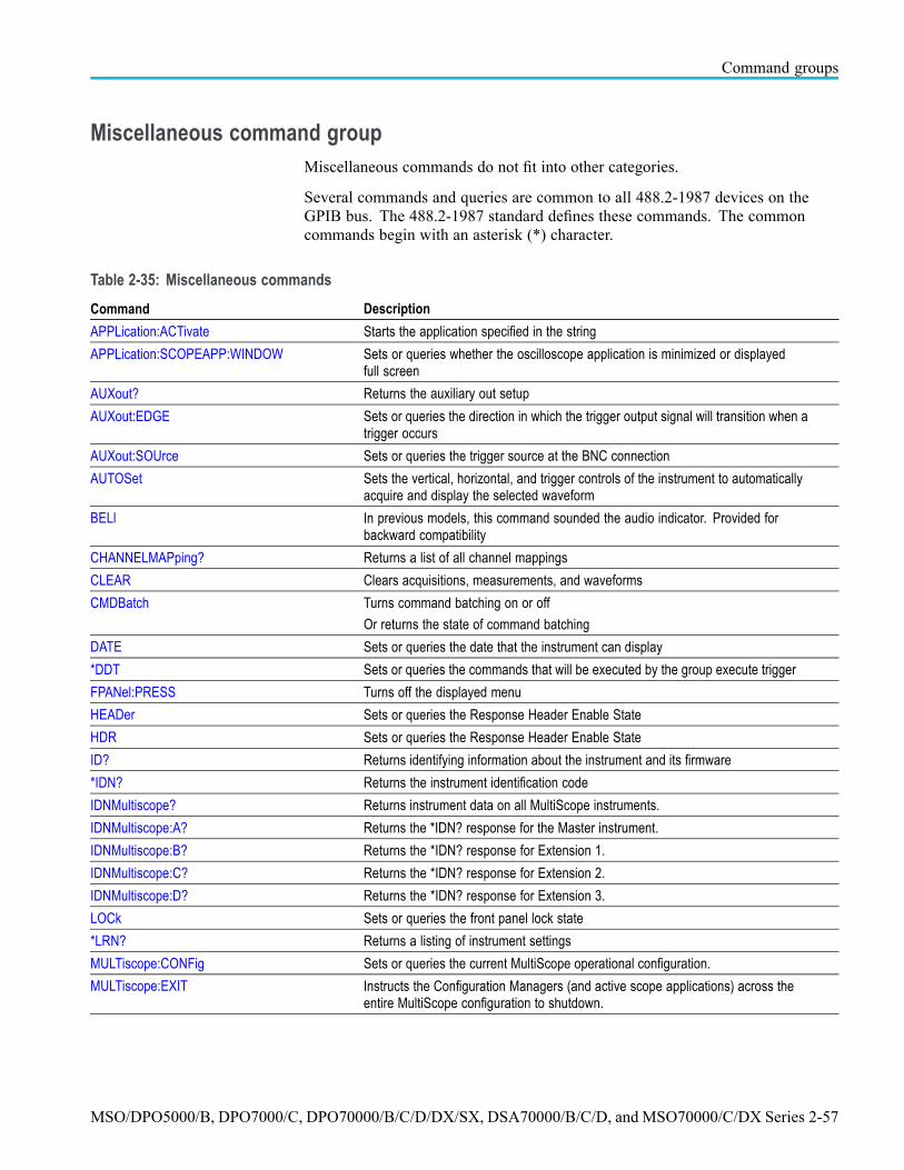
Command groups
Miscellaneous command groupMiscellaneous commands do not fit into other categories.
Several commands and queries are common to all 488.2-1987 devices on theGPIB bus. The 488.2-1987 standard defines these commands. The commoncommands begin with an asterisk (*) character.
Table 2-35: Miscellaneous commands
Command Description
APPLication:ACTivate Starts the application specified in the string
APPLication:SCOPEAPP:WINDOW Sets or queries whether the oscilloscope application is minimized or displayedfull screen
AUXout? Returns the auxiliary out setup
AUXout:EDGE Sets or queries the direction in which the trigger output signal will transition when atrigger occurs
AUXout:SOUrce Sets or queries the trigger source at the BNC connection
AUTOSet Sets the vertical, horizontal, and trigger controls of the instrument to automaticallyacquire and display the selected waveform
BELl In previous models, this command sounded the audio indicator. Provided forbackward compatibility
CHANNELMAPping? Returns a list of all channel mappings
CLEAR Clears acquisitions, measurements, and waveforms
CMDBatch Turns command batching on or off
Or returns the state of command batching
DATE Sets or queries the date that the instrument can display
*DDT Sets or queries the commands that will be executed by the group execute trigger
FPANel:PRESS Turns off the displayed menu
HEADer Sets or queries the Response Header Enable State
HDR Sets or queries the Response Header Enable State
ID? Returns identifying information about the instrument and its firmware
*IDN? Returns the instrument identification code
IDNMultiscope? Returns instrument data on all MultiScope instruments.
IDNMultiscope:A? Returns the *IDN? response for the Master instrument.
IDNMultiscope:B? Returns the *IDN? response for Extension 1.
IDNMultiscope:C? Returns the *IDN? response for Extension 2.
IDNMultiscope:D? Returns the *IDN? response for Extension 3.
LOCk Sets or queries the front panel lock state
*LRN? Returns a listing of instrument settings
MULTiscope:CONFig Sets or queries the current MultiScope operational configuration.
MULTiscope:EXIT Instructs the Configuration Managers (and active scope applications) across theentire MultiScope configuration to shutdown.
MSO/DPO5000/B, DPO7000/C, DPO70000/B/C/D/DX/SX, DSA70000/B/C/D, and MSO70000/C/DX Series 2-57

Command groups
Table 2-35: Miscellaneous commands (cont.)
Command Description
MULTiscope:RESTART Instructs the Configuration Managers (and active scope applications) across theentire MultiScope configuration to exit and restart themselves.
MULTiscope:STATUS? Returns the current state of the MultiScope system.
NEWpass Changes the password for user protected data
PASSWord Provides access for changing user protected data
REM Specifies a comment which is ignored by the instrument
ROSc:OUT:FREQuency Sets or queries the selected frequency for the timebase reference output signal
ROSc:OUT:ULTRAsync Sets or queries the state of the UltraSync 12.5 GHz Clock Out.
ROSc:SOUrce Sets or queries the selected source for the time base reference oscillator
ROSc:STATE? Returns whether the time base reference oscillator is locked
ROSc:TRACking Sets or queries the selected source for the time base reference oscillator. Thereference oscillator locks to this source
SET? Returns a listing of instrument settings
TEKSecure Initializes both waveform and setup memories
TIME Sets or queries the time displayed by the instrument
*TRG Performs the group execute trigger (GET)
*TST? Tests the GPIB interface and returns status
UNLock Unlocks front panel
USBTMC:PRODUCTID:DECimal? Queries the USBTMC product ID in decimal
USBTMC:PRODUCTID:HEXadecimal? Queries the USBTMC product ID in hexadecimal
USBTMC:SERIALnumber? Queries the instrument serial number
USBTMC:VENDORID:DECimal? Queries the USBTMC product ID in decimal
USBTMC:VENDORID:HEXadecimal? Queries the USBTMC product ID in hexadecimal
VERBose Sets or queries the verbose state
2-58 MSO/DPO5000/B, DPO7000/C, DPO70000/B/C/D/DX/SX, DSA70000/B/C/D, and MSO70000/C/DX Series

Command groups
Save and Recall command groupUse the commands in the Save and Recall Command Group to store and retrieveinternal waveforms and settings. When you save a setup, you save all the settingsof the instrument. When you recall a setup, the instrument restores itself to thestate that it was in when you originally saved that setting.
Table 2-36: Save and Recall commands
Command Description
*RCL Restores the state of the instrument from a copy of the setting stored in memory
*SAV Stores the current instrument state to a specified memory location
*SDS Changes the specified setup to reference the factory setup instead of the user setup
DELEte:SETUp Removes stored setups from memory and initializes the location with the factorydefault setups
DELEte:WAVEform Deletes (one or all of) the stored reference waveforms from memory
FACtory Resets the instrument to factory default settings
RECAll:SETUp Recalls saved instrument settings
RECAll:SETUp:DESKew Sets or queries the deskew values that are affected by a default setup or a recalledsetup
RECAll:WAVEform Recalls a stored waveform to a reference location
SAVe:EVENTtable:BUS<x> Saves the event table contents of the specified bus in CSV format, to the file thatyou specify by <string>
SAVe:MARKS Saves the user search marks in CSV format, to the file that you specify
SAVe:SETUp Saves the current front panel setup to a specified memory location or file
SAVe:WAVEform Saves a waveform to one of four reference memory locations or a mass storage file
SAVe:WAVEform:DATa:STARt Sets or queries save waveform starting waveform data sample.
SAVe:WAVEform:DATa:STOP Sets or queries save waveform ending waveform data sample.
SAVe:WAVEform:FILEFormat Sets or queries the format for saved waveforms
SAVe:WAVEform:FORCESAMEFilesize Sets or queries the save waveform force same file size feature
SETUp:NAMe Sets or queries the user-defined setup label
MSO/DPO5000/B, DPO7000/C, DPO70000/B/C/D/DX/SX, DSA70000/B/C/D, and MSO70000/C/DX Series 2-59
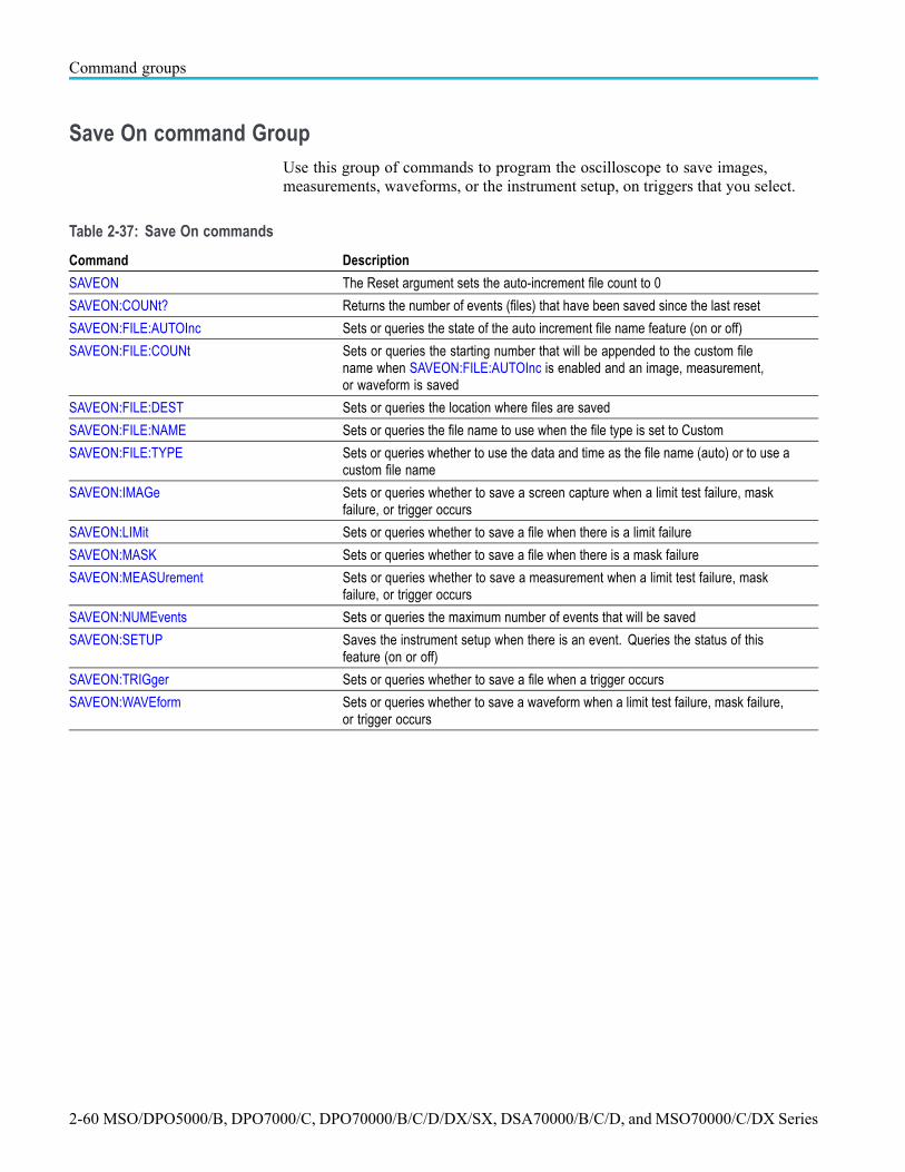
Command groups
Save On command GroupUse this group of commands to program the oscilloscope to save images,measurements, waveforms, or the instrument setup, on triggers that you select.
Table 2-37: Save On commands
Command Description
SAVEON The Reset argument sets the auto-increment file count to 0
SAVEON:COUNt? Returns the number of events (files) that have been saved since the last reset
SAVEON:FILE:AUTOInc Sets or queries the state of the auto increment file name feature (on or off)
SAVEON:FILE:COUNt Sets or queries the starting number that will be appended to the custom filename when SAVEON:FILE:AUTOInc is enabled and an image, measurement,or waveform is saved
SAVEON:FILE:DEST Sets or queries the location where files are saved
SAVEON:FILE:NAME Sets or queries the file name to use when the file type is set to Custom
SAVEON:FILE:TYPE Sets or queries whether to use the data and time as the file name (auto) or to use acustom file name
SAVEON:IMAGe Sets or queries whether to save a screen capture when a limit test failure, maskfailure, or trigger occurs
SAVEON:LIMit Sets or queries whether to save a file when there is a limit failure
SAVEON:MASK Sets or queries whether to save a file when there is a mask failure
SAVEON:MEASUrement Sets or queries whether to save a measurement when a limit test failure, maskfailure, or trigger occurs
SAVEON:NUMEvents Sets or queries the maximum number of events that will be saved
SAVEON:SETUP Saves the instrument setup when there is an event. Queries the status of thisfeature (on or off)
SAVEON:TRIGger Sets or queries whether to save a file when a trigger occurs
SAVEON:WAVEform Sets or queries whether to save a waveform when a limit test failure, mask failure,or trigger occurs
2-60 MSO/DPO5000/B, DPO7000/C, DPO70000/B/C/D/DX/SX, DSA70000/B/C/D, and MSO70000/C/DX Series

Command groups
Search and Mark command groupUse search and mark commands to seek out and identify information in waveformrecords that warrant further investigation.
Table 2-38: Search and Mark commands
Command Description
MARK Moves to the next or previous reference mark, or queries the current mark setup
MARK:CREATE Creates a mark on a specified waveform or all waveforms in a column
MARK:DELEte Deletes a mark on a particular waveform, all waveforms in a column, the selectedmark, or all marks
MARK:FREE? Returns how many user marks are available for use
MARK:SELECTED:END? Returns the end of the selected mark, 0 to 100% of the waveform
MARK:SELECTED:FOCUS? Returns the focus of the selected mark, 0 to 100% of the waveform
MARK:SELECTED:LABel Sets or queries the label for the selected mark
MARK:SELECTED:MARKSINCOLumn? Returns the number of marks in the current zoom pixel column
MARK:SELECTED:OWNer? Returns the owner of the selected mark
MARK:SELECTED:SOUrce? Sets or queries the source waveform for the selected mark
MARK:SELECTED:STARt? Returns the starting point of the selected mark, 0 to 100% of the waveform
MARK:SELECTED:STATE Returns the on or off state of the selected mark. The selected mark is at or nearthe center of the display
MARK:SELECTED:ZOOm:POSition? Returns the position of the selected mark, 0 to 100% of the zoom overview window
MARK:SELECTED:ZOOm:SCAle? Returns the scale of the selected mark, 0 to 100% of the zoom overview window
MARK:TOTal? Returns how many marks are currently in use
SEARCH:MARKALLevents Sets or queries the mark all trigger events setting
SEARCH:SEARCH<x> Converts the specified search marks to the user marks
SEARCH:SEARCH<x>:COPy Copies the search criteria to the trigger, the trigger criteria to a search, or copysearch to search
SEARCH:SEARCH<x>:STATE Selects which search is selected
SEARCH:SEARCH<x>:TOTAL? Returns the total number of matches for the search. The total number of matchesmay be more than the number of marks placed
SEARCH:SEARCH<x>:TRIGger:A:DDRMemory:AUTOBitrate
Sets or queries the auto bit rate setting to determine where to place a mark
SEARCH:SEARCH<x>:TRIGger:A:BUS:CAN:CONDition
Sets or queries the CAN bus trigger condition
SEARCH:SEARCH<x>:TRIGger:A:BUS:CAN:DATa:VALue
Sets or queries the CAN bus trigger data value
SEARCH:SEARCH<x>:TRIGger:A:BUS:CAN:FRAMEtype
Sets or queries CAN bus trigger frame type
SEARCH:SEARCH<x>:TRIGger:A:BUS:CAN:DATa:FORMat
Sets or queries the CAN bus trigger data format
MSO/DPO5000/B, DPO7000/C, DPO70000/B/C/D/DX/SX, DSA70000/B/C/D, and MSO70000/C/DX Series 2-61

Command groups
Table 2-38: Search and Mark commands (cont.)
Command Description
SEARCH:SEARCH<x>:TRIGger:A:BUS:CAN:DATa:SIZe
Sets or queries the CAN bus trigger data size
SEARCH:SEARCH<x>:TRIGger:A:BUS:CAN:DATa:QUALifier
Sets or queries the CAN bus trigger data qualifier
SEARCH:SEARCH<x>:TRIGger:A:BUS:CAN:IDentifier:DIRection
Sets or queries the CAN bus identifier direction
SEARCH:SEARCH<x>:TRIGger:A:BUS:CAN:IDentifier:FORMat
Sets or queries the CAN bus trigger identifier format
SEARCH:SEARCH<x>:TRIGger:A:BUS:CAN:IDentifier:MODe
Sets or queries the CAN bus trigger identifier mode
SEARCH:SEARCH<x>:TRIGger:A:BUS:CAN:IDentifier:VALue
Sets or queries CAN bus trigger identifier value
SEARCH:SEARCH<x>:TRIGger:A:BUS:ETHERnet:CONDition
Specifies a field or condition within an Ethernet frame to search on
SEARCH:SEARCH<x>:TRIGger:A:BUS:ETHERnet:DATa:OFFSet
Specifies the data offset value, in bytes, to use when searching on the Ethernetdata field
SEARCH:SEARCH<x>:TRIGger:A:BUS:ETHERnet:DATa:SIZe
Specifies the number of contiguous TCP/IPv4/MAC client bytes to use whensearching on the Ethernet data field
SEARCH:SEARCH<x>:TRIGger:A:BUS:ETHERnet:DATa:VALue
Specifies the binary value to use when searching on the Ethernet data field
SEARCH:SEARCH<x>:TRIGger:A:BUS:ETHERnet:IPHeader:DESTinationaddr:VALue
Specifies the 32-bit value to use when searching on the Ethernet IPv4 headeraddress destination field
SEARCH:SEARCH<x>:TRIGger:A:BUS:ETHERnet:IPHeader:DESTinationaddr:FORMat
Specifies the format (binary or hex) of the bit pattern to use when searching on theEthernet IPv4 header address destination field
SEARCH:SEARCH<x>:TRIGger:A:BUS:ETHERnet:IPHeader:PROTOcol:VALue
Specifies the 8-bit value to use when searching on the Ethernet IPv4 headerprotocol field
SEARCH:SEARCH<x>:TRIGger:A:BUS:ETHERnet:IPHeader:PROTOcol:FORMat
Specifies the data format (binary or hex) of the bit pattern to use when searching onthe Ethernet IPv4 header protocol field
SEARCH:SEARCH<x>:TRIGger:A:BUS:ETHERnet:IPHeader:SOUrceaddr:VALue
Specifies the 32-bit value to use when searching on the Ethernet IPv4 headeraddress source field
SEARCH:SEARCH<x>:TRIGger:A:BUS:ETHERnet:IPHeader:SOUrceaddr:FORMat
Specifies the data format (binary or hex) of the bit pattern to use when searching onthe Ethernet IPv4 header address source field
SEARCH:SEARCH<x>:TRIGger:A:BUS:ETHERnet:MAC:ADDRess:DESTination:VALue
Specifies the 48-bit value to use when searching on the Ethernet MAC addressdestination field
SEARCH:SEARCH<x>:TRIGger:A:BUS:ETHERnet:MAC:ADDRess:DESTination:FORMat
Specifies the data format (binary or hex) of the bit pattern to use when searching onthe Ethernet MAC address destination field
SEARCH:SEARCH<x>:TRIGger:A:BUS:ETHERnet:MAC:ADDRess:SOUrce:FORMat
Specifies the format (binary or hex) of the bit pattern to use when searching onthe Ethernet MAC address source field
2-62 MSO/DPO5000/B, DPO7000/C, DPO70000/B/C/D/DX/SX, DSA70000/B/C/D, and MSO70000/C/DX Series

Command groups
Table 2-38: Search and Mark commands (cont.)
Command Description
SEARCH:SEARCH<x>:TRIGger:A:BUS:ETHERnet:MAC:ADDRess:SOUrce:VALue
Specifies the 48-bit value to use when searching on the Ethernet MAC addresssource field
SEARCH:SEARCH<x>:TRIGger:A:BUS:ETHERnet:MAC{:LENgth|:TYPe}:VALue
Specifies the 16-bit value to use when searching on the Ethernet MAC length/type
SEARCH:SEARCH<x>:TRIGger:A:BUS:ETHERnet:MAC{:LENgth|:TYPe}:FORMat
Specifies the format (binary or hex) of the bit pattern to use when searching on theEthernet MAC length or type
SEARCH:SEARCH<x>:TRIGger:A:BUS:ETHERnet:QTAG:VALue
Specifies the 32-bit value to use when searching on the Ethernet Q-Tag field
SEARCH:SEARCH<x>:TRIGger:A:BUS:ETHERnet:QTAG:FORMat
Specifies the data format (binary or hex) to use when searching on the Q-Tag field
SEARCH:SEARCH<x>:TRIGger:A:BUS:ETHERnet:QUALifier
Specifies the qualifier to be used when the Ethernet search condition is set toMACLENgth or DATa
SEARCH:SEARCH<x>:TRIGger:A:BUS:ETHERnet:TCPHeader:ACKnum:VALue
Specifies the 32-bit value to use when searching on the Ethernet TCP headeracknowledgement number
SEARCH:SEARCH<x>:TRIGger:A:BUS:ETHERnet:TCPHeader:ACKnum:FORMat
Specifies the format (binary or hex) of the bit pattern to use when searching on theEthernet TCP header acknowledgement number
SEARCH:SEARCH<x>:TRIGger:A:BUS:ETHERnet:TCPHeader:DESTinationport:VALue
Specifies the 16-bit value to use when searching on the Ethernet TCP headerdestination port number
SEARCH:SEARCH<x>:TRIGger:A:BUS:ETHERnet:TCPHeader:DESTinationport:FORMat
Specifies the format (binary or hex) of the bit pattern to use when searching on theEthernet TCP header destination port number
SEARCH:SEARCH<x>:TRIGger:A:BUS:ETHERnet:TCPHeader:SEQnum:VALue
Specifies the 32-bit value to use when searching on the Ethernet TCP headersequence number
SEARCH:SEARCH<x>:TRIGger:A:BUS:ETHERnet:TCPHeader:SEQnum:FORMat
Specifies the format (binary or hex) of the bit pattern to use when searching on theEthernet TCP header sequence number
SEARCH:SEARCH<x>:TRIGger:A:BUS:ETHERnet:TCPHeader:SOUrceport:VALue
Specifies the 16-bit value to use when searching on the Ethernet TCP headersource port number
SEARCH:SEARCH<x>:TRIGger:A:BUS:ETHERnet:TCPHeader:SOUrceport:FORMat
Specifies the format (binary or hex) of the bit pattern to use when searching on theEthernet TCP header source port number
SEARCH:SEARCH<x>:TRIGger:A:BUS:ETHERnet:DATa:FORMat
Specifies the format (binary or hex) of the bit pattern to use when searching onthe Ethernet data field
SEARCH:SEARCH<x>:TRIGger:A:BUS:FLEXRAY:CONDition
Sets or queries FLEXRAY bus search trigger condition
SEARCH:SEARCH<x>:TRIGger:A:BUS:FLEXRAY:CYCLEcount:FORMat
Sets or queries the FLEXRAY bus search cycle count format
SEARCH:SEARCH<x>:TRIGger:A:BUS:FLEXRAY:CYCLEcount:QUALifier
Sets or queries the FLEXRAY bus search trigger cycle count qualifier
SEARCH:SEARCH<x>:TRIGger:A:BUS:FLEXRAY:CYCLEcount:VALue
Sets or queries the FLEXRAY bus search cycle count value
SEARCH:SEARCH<x>:TRIGger:A:BUS:FLEXRAY:DATa:FORMat
Sets or queries FLEXRAY bus search data format
MSO/DPO5000/B, DPO7000/C, DPO70000/B/C/D/DX/SX, DSA70000/B/C/D, and MSO70000/C/DX Series 2-63

Command groups
Table 2-38: Search and Mark commands (cont.)
Command Description
SEARCH:SEARCH<x>:TRIGger:A:BUS:FLEXRAY:DATa:OFFSet
Sets or queries the FLEXRAY bus search trigger data offset
SEARCH:SEARCH<x>:TRIGger:A:BUS:FLEXRAY:DATa:QUALifier
Sets or queries the FLEXRAY bus search trigger data qualifier
SEARCH:SEARCH<x>:TRIGger:A:BUS:FLEXRAY:DATa:SIZe
Sets or queries the FLEXRAY bus search trigger data size
SEARCH:SEARCH<x>:TRIGger:A:BUS:FLEXRAY:DATa:VALue
Sets or queries the FLEXRAY bus search trigger data value
SEARCH:SEARCH<x>:TRIGger:A:BUS:FLEXRAY:EOFTYPE
Sets or queries the FLEXRAY bus search trigger end of file type
SEARCH:SEARCH<x>:TRIGger:A:BUS:FLEXRAY:ERRTYPE
Sets or queries the FLEXRAY bus search trigger error type
SEARCH:SEARCH<x>:TRIGger:A:BUS:FLEXRAY:FRAMEType
Sets or queries the FLEXRAY bus search trigger frame type
SEARCH:SEARCH<x>:TRIGger:A:BUS:FLEXRAY:HEADER:CRC
Sets or queries the FLEXRAY bus search trigger header CRC
SEARCH:SEARCH<x>:TRIGger:A:BUS:FLEXRAY:HEADER:CYCLECount
Sets or queries the FLEXRAY bus search trigger header cycle count
SEARCH:SEARCH<x>:TRIGger:A:BUS:FLEXRAY:HEADER:FRAMEID
Sets or queries the FLEXRAY bus search trigger header frame id
SEARCH:SEARCH<x>:TRIGger:A:BUS:FLEXRAY:HEADER:INDBits
Sets or queries the FLEXRAY bus search header Indicator Bits
SEARCH:SEARCH<x>:TRIGger:A:BUS:FLEXRAY:HEADER:PAYLENgth
Sets or queries the FLEXRAY bus search trigger header payload length
SEARCH:SEARCH<x>:TRIGger:A:BUS:FLEXRAY:IDentifier:FORMat
Sets or queries the FLEXRAY bus search trigger identifier format
SEARCH:SEARCH<x>:TRIGger:A:BUS:FLEXRAY:IDentifier:QUALifier
Sets or queries the FLEXRAY bus search trigger identifier qualifier
SEARCH:SEARCH<x>:TRIGger:A:BUS:FLEXRAY:IDentifier:VALue
Sets or queries the FLEXRAY bus search trigger identifier value
SEARCH:SEARCH<x>:TRIGger:A:BUS:LIN:CONDition
Sets or queries the LIN bus search trigger condition
SEARCH:SEARCH<x>:TRIGger:A:BUS:LIN:DATa:FORMat
Sets or queries the LIN bus search trigger data format
SEARCH:SEARCH<x>:TRIGger:A:BUS:LIN:DATa:QUALifier
Sets or queries the LIN bus search trigger data qualifier
SEARCH:SEARCH<x>:TRIGger:A:BUS:LIN:DATa:SIZe
Sets or queries the LIN bus search trigger data size
SEARCH:SEARCH<x>:TRIGger:A:BUS:LIN:DATa:VALue
Sets or queries the LIN bus search trigger data value
SEARCH:SEARCH<x>:TRIGger:A:BUS:LIN:ERRTYPE
Sets or queries the LIN bus search trigger error type
2-64 MSO/DPO5000/B, DPO7000/C, DPO70000/B/C/D/DX/SX, DSA70000/B/C/D, and MSO70000/C/DX Series

Command groups
Table 2-38: Search and Mark commands (cont.)
Command Description
SEARCH:SEARCH<x>:TRIGger:A:BUS:LIN:IDentifier:FORMat
Sets or queries the LIN bus search trigger identifier format
SEARCH:SEARCH<x>:TRIGger:A:BUS:LIN:IDentifier:VALue
Sets or queries the LIN bus search trigger identifier value
SEARCH:SEARCH<x>:TRIGger:A:BUS:I2C:ADDress:FORMat
Sets or queries the address format for the I2C bus trigger search to determinewhere to place a mark
SEARCH:SEARCH<x>:TRIGger:A:BUS:I2C:ADDress:MODe
Sets or queries the address mode for the specified I2C bus trigger search todetermine where to place a mark
SEARCH:SEARCH<x>:TRIGger:A:BUS:I2C:ADDress:TYPe
Sets or queries the address type for the specified I2C bus trigger search todetermine where to place a mark
SEARCH:SEARCH<x>:TRIGger:A:BUS:I2C:ADDress:VALue
Sets or queries the address string when the search condition for the specifiedsearch is Address or AddressData, to determine where to place a mark
SEARCH:SEARCH<x>:TRIGger:A:BUS:I2C:CONDition
Sets or queries the trigger condition for the specified I2C bus trigger search todetermine where to place a mark
SEARCH:SEARCH<x>:TRIGger:A:BUS:I2C:DATa:DIRection
Sets or queries the direction of the data for the I2C bus trigger search to determinewhere to place a mark
SEARCH:SEARCH<x>:TRIGger:A:BUS:I2C:DATa:FORMat
Sets or queries the trigger data format for the specified I2C bus trigger search todetermine where to place a mark
SEARCH:SEARCH<x>:TRIGger:A:BUS:I2C:DATa:SIZe
Sets or queries the length of the data string in bytes used for the specified I2C bustrigger search to determine where to place a mark
SEARCH:SEARCH<x>:TRIGger:A:BUS:I2C:DATa:VALue
Sets or queries the data value of the data token for the specified I2C bus triggersearch to determine where to place a mark
SEARCH:SEARCH<x>:TRIGger:A:BUS:MIL1553B:COMMAND:ADDRess:FORMat
Sets the data format of the address (either binary or hex) to use in a MIL-STD-1553bus command word search
SEARCH:SEARCH<x>:TRIGger:A:BUS:MIL1553B:COMMAND:ADDRess:VALue
Specifies the value of the 5-bit remote terminal address to use in a MIL-STD-1553bus command word search
SEARCH:SEARCH<x>:TRIGger:A:BUS:MIL1553B:COMMAND:ADDRess:QUALifier
Specifies the qualifier to use when searching on a MIL-STD-1553 bus commandword remote terminal address field
SEARCH:SEARCH<x>:TRIGger:A:BUS:MIL1553B:COMMAND:COUNt
Specifies the bit pattern for the 5-bit Word Count/Mode Code sub-address field touse in a MIL-STD-1553 bus command word trigger
SEARCH:SEARCH<x>:TRIGger:A:BUS:MIL1553B:COMMAND:COUNt:FORMat
Specifies the data format (binary or hex) of the bit pattern for the 5-bit WordCount/Mode Code field to use in a MIL-STD-1553 bus command word search
SEARCH:SEARCH<x>:TRIGger:A:BUS:MIL1553B:COMMAND:PARity
Specifies the parity to use in a MIL-STD-1553 bus command word search
SEARCH:SEARCH<x>:TRIGger:A:BUS:MIL1553B:COMMAND:SUBADdress
Specifies the 5 bit sub-address to use in a MIL-STD-1553 bus command wordsub-address search
SEARCH:SEARCH<x>:TRIGger:A:BUS:MIL1553B:COMMAND:SUBADdress:FORMat
Specifies the data format (binary or hex) of the sub-address field bit pattern to usein a MIL-STD-1553 bus command word sub-address search
SEARCH:SEARCH<x>:TRIGger:A:BUS:MIL1553B:COMMAND:TRBit
Specifies to search on either a “transmit” or a “receive” signal for the transmit/receivebit (bit 9), for a MIL-STD-1553 bus command word search
MSO/DPO5000/B, DPO7000/C, DPO70000/B/C/D/DX/SX, DSA70000/B/C/D, and MSO70000/C/DX Series 2-65

Command groups
Table 2-38: Search and Mark commands (cont.)
Command Description
SEARCH:SEARCH<x>:TRIGger:A:BUS:MIL1553B:CONDition
Specifies which word type or condition within a MIL-STD-1553 bus word to search on
SEARCH:SEARCH<x>:TRIGger:A:BUS:MIL1553B:DATA:FORMat
Specifies the format (binary or hex) of the bit pattern to use for a MIL-STD-1553bus data word search
SEARCH:SEARCH<x>:TRIGger:A:BUS:MIL1553B:DATA:PARity
Specifies the parity to use when searching on a MIL-STD-1553 bus data wordparity bit
SEARCH:SEARCH<x>:TRIGger:A:BUS:MIL1553B:DATA:VALue
Specifies the value to use for a MIL-STD-1553 bus data word search
SEARCH:SEARCH<x>:TRIGger:A:BUS:MIL1553B:ERRTYPE
Specifies the signaling error type to use for a MIL-STD-1553 bus data word search:Parity, Sync, Manchester, or Data
SEARCH:SEARCH<x>:TRIGger:A:BUS:MIL1553B:STATUS:BIT:PARity
Specifies the parity to use when searching on the MIL-STD-1553 status bit field
SEARCH:SEARCH<x>:TRIGger:A:BUS:MIL1553B:STATUS:ADDRess:FORMat
Specifies the format (binary or hex) of the bit pattern to use when searching onthe MIL-STD-1553 status address field
SEARCH:SEARCH<x>:TRIGger:A:BUS:MIL1553B:STATUS:ADDRess:QUALifier
Specifies the qualifier to use when searching on the MIL-STD-1553 status addressfield
SEARCH:SEARCH<x>:TRIGger:A:BUS:MIL1553B:STATUS:ADDRess:VALue
Specifies the value of the 5-bit remote terminal address to use when searching onthe MIL-STD-1553 status address field
SEARCH:SEARCH<x>:TRIGger:A:BUS:MIL1553B:STATUS:BIT:BCR
Specifies the status word broadcast command received (BCR) bit value (bit 15) touse when searching on the MIL-STD-1553 status bit field
SEARCH:SEARCH<x>:TRIGger:A:BUS:MIL1553B:STATUS:BIT:BUSY
Specifies the status word busy bit value (bit 16) to use when searching on theMIL-STD-1553 status bit field
SEARCH:SEARCH<x>:TRIGger:A:BUS:MIL1553B:STATUS:BIT:DBCA
Specifies the status word dynamic bus control acceptance (DBCA) bit value (bit 18)to use when searching on the MIL-STD-1553 status bit field
SEARCH:SEARCH<x>:TRIGger:A:BUS:MIL1553B:STATUS:BIT:INSTR
Specifies the status word instrumentation bit value (bit 10) to use when searchingon the MIL-STD-1553 status bit field
SEARCH:SEARCH<x>:TRIGger:A:BUS:MIL1553B:STATUS:BIT:ME
Specifies the status word message error bit value (bit 9) to use when searching onthe MIL-STD-1553 status bit field
SEARCH:SEARCH<x>:TRIGger:A:BUS:MIL1553B:STATUS:BIT:SRQ
Specifies the status word service request (SRQ) bit value (bit 11) to use whensearching on the MIL-STD-1553 status bit field
SEARCH:SEARCH<x>:TRIGger:A:BUS:MIL1553B:STATUS:BIT:SUBSF
Specifies the status word subsystem flag bit value (bit 17) to use when searching onthe MIL-STD-1553 status bit field
SEARCH:SEARCH<x>:TRIGger:A:BUS:MIL1553B:STATUS:BIT:TF
Specifies the status word terminal flag bit value (bit 19) to use when searching onthe MIL-STD-1553 status bit field
SEARCH:SEARCH<x>:TRIGger:A:BUS:MIL1553B:TIME:LESSLimit
Specifies either the minimum remote terminal response time (RT) limit, in seconds,for the amount of time the terminal has to transmit, or else it specifies the minimuminter-message gap (IMG)
SEARCH:SEARCH<x>:TRIGger:A:BUS:MIL1553B:TIME:MORELimit
Specifies either the maximum remote terminal response time (RT) limit, in seconds,for the amount of time the terminal has to transmit, or it specifies the maximuminter-message gap (IMG)
SEARCH:SEARCH<x>:TRIGger:A:BUS:MIL1553B:TIME:QUALifier
Specifies the qualifier to use when triggering on either the remote terminal responsetime (RT) or the inter-message gap (IMG)
2-66 MSO/DPO5000/B, DPO7000/C, DPO70000/B/C/D/DX/SX, DSA70000/B/C/D, and MSO70000/C/DX Series

Command groups
Table 2-38: Search and Mark commands (cont.)
Command Description
SEARCH:SEARCH<x>:TRIGger:A:BUS:MIPICSITWo:CONDition
Sets or queries the search condition for the specified MIPI CSI2 bus trigger searchto determine where to place a mark
SEARCH:SEARCH<x>:TRIGger:A:BUS:MIPICSITWo:DTLong
Sets or queries the data type for long packets for the specified MIPI CSI2 bus triggersearch to determine where to place a mark
SEARCH:SEARCH<x>:TRIGger:A:BUS:MIPICSITWo:DTShort
Sets or queries the data type for short packets for the specified MIPI CSI2 bustrigger search to determine where to place a mark
SEARCH:SEARCH<x>:TRIGger:A:BUS:MIPICSITWo:ERRor
Sets or queries the error type for the specified MIPI CSI2 bus trigger search todetermine where to place a mark
SEARCH:SEARCH<x>:TRIGger:A:BUS:MIPICSITWo:ESCape
Sets or queries the Escape command for the specified MIPI CSI2 bus trigger searchto determine where to place a mark
SEARCH:SEARCH<x>:TRIGger:A:BUS:MIPICSITWo:OFFset:VALue
Sets or queries the offset value for the specified MIPI CSI2 bus trigger search todetermine where to place a mark
SEARCH:SEARCH<x>:TRIGger:A:BUS:MIPICSITWo:PACKetdata:FORMat
Sets or queries the format of the packet data for the specified MIPI CSI2 bus triggersearch to determine where to place a mark
SEARCH:SEARCH<x>:TRIGger:A:BUS:MIPICSITWo:PACKetdata:VALue
Sets or queries the value of the packet data string for a specified MIPI CSI2 bustrigger search to determine where to place a mark
SEARCH:SEARCH<x>:TRIGger:A:BUS:MIPICSITWo:PAYLoad:FORMat
Sets or queries the generic payload format for the specified MIPI CSI2 bus triggersearch to determine where to place a mark
SEARCH:SEARCH<x>:TRIGger:A:BUS:MIPICSITWo:PAYLoad:SIZe
Sets or queries the generic payload size of the specified MIPI CSI2 bus triggersearch to determine where to place a mark
SEARCH:SEARCH<x>:TRIGger:A:BUS:MIPICSITWo:PAYLoad:VALue
Sets or queries the generic payload value string of the specified MIPI CSI2 bustrigger search to determine where to place a mark
SEARCH:SEARCH<x>:TRIGger:A:BUS:MIPICSITWo:PIXel:VALue
Sets or queries the pixel value for the specified MIPI CSI2 bus trigger search todetermine where to place a mark
SEARCH:SEARCH<x>:TRIGger:A:BUS:MIPICSITWo:RAW:QUAlifier
Sets or queries the RAW qualifier for the specified MIPI CSI2 bus trigger search todetermine where to place a mark
SEARCH:SEARCH<x>:TRIGger:A:BUS:MIPICSITWo:RAW:VALue
Sets or queries the RAW value for the specified MIPI CSI2 bus trigger search
SEARCH:SEARCH<x>:TRIGger:A:BUS:MIPICSITWo:RGB:BLUe:QUAlifier
Sets or queries the RGB Blue qualifier for the specified MIPI CSI2 bus triggersearch to determine where to place a mark
SEARCH:SEARCH<x>:TRIGger:A:BUS:MIPICSITWo:RGB:BLUe:VALue
Sets or queries the RGB blue value for the for the specified MIPI CSI2 bus triggersearch to determine where to place a mark
SEARCH:SEARCH<x>:TRIGger:A:BUS:MIPICSITWo:RGB:GREen:QUAlifier
Sets or queries the RGB blue value for the for the specified MIPI CSI2 bus triggersearch to determine where to place a mark
SEARCH:SEARCH<x>:TRIGger:A:BUS:MIPICSITWo:RGB:GREen:VALue
Sets or queries the RGB Green value for the specified MIPI CSI2 bus trigger searchto determine where to place a mark
SEARCH:SEARCH<x>:TRIGger:A:BUS:MIPICSITWo:RGB:RED:QUAlifier
Sets or queries the RGB Red qualifier for the specified MIPI CSI2 bus trigger searchto determine where to place a mark
SEARCH:SEARCH<x>:TRIGger:A:BUS:MIPICSITWo:RGB:RED:VALue
Sets or queries the RGB Red value for the specified MIPI CSI2 bus trigger search todetermine where to place a mark
SEARCH:SEARCH<x>:TRIGger:A:BUS:MIPICSITWo:VC
Sets or queries the Virtual Channel for the specified MIPI CSI2 bus trigger search todetermine where to place a mark
MSO/DPO5000/B, DPO7000/C, DPO70000/B/C/D/DX/SX, DSA70000/B/C/D, and MSO70000/C/DX Series 2-67

Command groups
Table 2-38: Search and Mark commands (cont.)
Command Description
SEARCH:SEARCH<x>:TRIGger:A:BUS:MIPICSITWo:WARNing
Sets or queries the warning type for a specified MIPI CSI2 bus trigger search todetermine where to place a mark
SEARCH:SEARCH<x>:TRIGger:A:BUS:MIPICSITWo:WC:VALue
Sets or queries the word count value for a specified MIPI CSI2 bus trigger search todetermine where to place a mark
SEARCH:SEARCH<x>:TRIGger:A:BUS:MIPICSITWo:YUV:U:QUAlifier
Sets or queries the YUV U qualifier for the specified MIPI CSI2 bus trigger search todetermine where to place a mark
SEARCH:SEARCH<x>:TRIGger:A:BUS:MIPICSITWo:YUV:U:VALue
Sets or queries the YUV U value for the specified MIPI CSI2 bus trigger search todetermine where to place a mark
SEARCH:SEARCH<x>:TRIGger:A:BUS:MIPICSITWo:YUV:V:QUAlifier
Sets or queries the YUV V qualifier for the specified MIPI CSI2 bus trigger search todetermine where to place a mark
SEARCH:SEARCH<x>:TRIGger:A:BUS:MIPICSITWo:YUV:V:VALue
Sets or queries the YUV V value for the specified MIPI CSI2 bus trigger search todetermine where to place a mark
SEARCH:SEARCH<x>:TRIGger:A:BUS:MIPICSITWo:YUV:Y:QUAlifier
Sets or queries the YUV Y qualifier for the specified MIPI CSI2 bus trigger search todetermine where to place a mark
SEARCH:SEARCH<x>:TRIGger:A:BUS:MIPICSITWo:YUV:Y:VALue
Sets or queries the YUV Y value for the specified MIPI CSI2 bus trigger search todetermine where to place a mark
SEARCH:SEARCH<x>:TRIGger:A:BUS:MIPIDSIOne:ACKERRreport
Sets or queries the Acknowledge and Error Report for the specified MIPI DSI1 bustrigger search to determine where to place a mark
SEARCH:SEARCH<x>:TRIGger:A:BUS:MIPIDSIOne:CONDition
Sets or queries the search condition for the specified MIPI DSI1 bus trigger searchto determine where to place a mark
SEARCH:SEARCH<x>:TRIGger:A:BUS:MIPIDSIOne:DIRection
Sets or queries the direction for the specified MIPI DSI1 bus trigger search todetermine where to place a mark
SEARCH:SEARCH<x>:TRIGger:A:BUS:MIPIDSIOne:DTLong
Sets or queries the data type for long packets for the specified MIPI DSI1 bus triggersearch to determine where to place a mark
SEARCH:SEARCH<x>:TRIGger:A:BUS:MIPIDSIOne:DTShort
Sets or queries the data type for short packets for the specified MIPI DSI1 bustrigger search to determine where to place a mark
SEARCH:SEARCH<x>:TRIGger:A:BUS:MIPIDSIOne:ERRor
Sets or queries the error type for the specified MIPI DSI1 bus trigger search todetermine where to place a mark
SEARCH:SEARCH<x>:TRIGger:A:BUS:MIPIDSIOne:ESCape
Sets or queries the Escape Command for the specified MIPI DSI1 bus triggersearch to determine where to place a mark
SEARCH:SEARCH<x>:TRIGger:A:BUS:MIPIDSIOne:OFFset:VALue
Sets or queries the offset value for the specified MIPI DSI1 bus trigger search todetermine where to place a mark
SEARCH:SEARCH<x>:TRIGger:A:BUS:MIPIDSIOne:PACKetdata:FORMat
Sets or queries the format of the packet data for the specified MIPI DSI1 bus triggersearch to determine where to place a mark
SEARCH:SEARCH<x>:TRIGger:A:BUS:MIPIDSIOne:PACKetdata:VALUEOne
Sets or queries the value of the first byte (8 bits) of a packet data string for aspecified MIPI DSI1 bus trigger search to determine where to place a mark
SEARCH:SEARCH<x>:TRIGger:A:BUS:MIPIDSIOne:PACKetdata:VALUETwo
Sets or queries the value of the second byte (8 bits) of a packet data string for aspecified MIPI DSI1 bus trigger search to determine where to place a mark
SEARCH:SEARCH<x>:TRIGger:A:BUS:MIPIDSIOne:PAYLoad:FORMat
Sets or queries the generic payload format for the specified MIPI DSI1 bus triggersearch to determine where to place a mark
SEARCH:SEARCH<x>:TRIGger:A:BUS:MIPIDSIOne:PAYLoad:SIZe
Sets or queries the generic payload size of the specified MIPI DSI1 bus triggersearch to determine where to place a mark
2-68 MSO/DPO5000/B, DPO7000/C, DPO70000/B/C/D/DX/SX, DSA70000/B/C/D, and MSO70000/C/DX Series

Command groups
Table 2-38: Search and Mark commands (cont.)
Command Description
SEARCH:SEARCH<x>:TRIGger:A:BUS:MIPIDSIOne:PAYLoad:VALue
Sets or queries the generic payload value string of the specified MIPI DSI1 bustrigger search to determine where to place a mark
SEARCH:SEARCH<x>:TRIGger:A:BUS:MIPIDSIOne:PIXel:VALue
Sets or queries the pixel value for the specified MIPI DSI1 bus trigger search todetermine where to place a mark
SEARCH:SEARCH<x>:TRIGger:A:BUS:MIPIDSIOne:RGB:BLUe:QUAlifier
Sets or queries the RGB Blue qualifier for the specified MIPI DSI1 bus triggersearch to determine where to place a mark
SEARCH:SEARCH<x>:TRIGger:A:BUS:MIPIDSIOne:RGB:BLUe:VALue
Sets or queries the RGB blue value for the for the specified MIPI DSI1 bus triggersearch to determine where to place a mark
SEARCH:SEARCH<x>:TRIGger:A:BUS:MIPIDSIOne:RGB:GREen:QUAlifier
Sets or queries the RGB Green qualifier for the specified MIPI DSI1 bus triggersearch to determine where to place a mark
SEARCH:SEARCH<x>:TRIGger:A:BUS:MIPIDSIOne:RGB:GREen:VALue
Sets or queries the RGB Green value for the specified MIPI DSI1 bus trigger searchto determine where to place a mark
SEARCH:SEARCH<x>:TRIGger:A:BUS:MIPIDSIOne:RGB:RED:QUAlifier
Sets or queries the RGB Red qualifier for the specified MIPI DSI1 bus trigger searchto determine where to place a mark
SEARCH:SEARCH<x>:TRIGger:A:BUS:MIPIDSIOne:RGB:RED:VALue
Sets or queries the RGB Red value for the specified MIPI DSI1 bus trigger search todetermine where to place a mark
SEARCH:SEARCH<x>:TRIGger:A:BUS:MIPIDSIOne:VC
Sets or queries the Virtual Channel for the specified MIPI DSI1 bus trigger search todetermine where to place a mark
SEARCH:SEARCH<x>:TRIGger:A:BUS:MIPIDSIOne:WARNing
Sets or queries the warning type for a specified MIPI DSI1 bus trigger search todetermine where to place a mark
SEARCH:SEARCH<x>:TRIGger:A:BUS:MIPIDSIOne:WC:VALue
Sets or queries the word count value for a specified MIPI DSI1 bus trigger search todetermine where to place a mark
SEARCH:SEARCH<x>:TRIGger:A:BUS:MIPIDSIOne:YCBCR:CB:QUAlifier
Sets or queries MIPI DSI-1 CB qualifier for the specified search
SEARCH:SEARCH<x>:TRIGger:A:BUS:MIPIDSIOne:YCBCR:CB:VALue
Sets or queries MIPI DSI-1 CB value for the specified search
SEARCH:SEARCH<x>:TRIGger:A:BUS:MIPIDSIOne:YCBCR:CR:QUAlifier
Sets or queries MIPI DSI-1 CR qualifier for the specified search
SEARCH:SEARCH<x>:TRIGger:A:BUS:MIPIDSIOne:YCBCR:CR:VALue
Sets or queries MIPI DSI-1 CR value for the specified search
SEARCH:SEARCH<x>:TRIGger:A:BUS:MIPIDSIOne:YCBCR:Y:QUAlifier
Sets or queries MIPI DSI-1 Y qualifier for the specified search
SEARCH:SEARCH<x>:TRIGger:A:BUS:MIPIDSIOne:YCBCR:Y:VALue
Sets or queries MIPI DSI-1 Y value for the specified search
SEARCH:SEARCH<x>:TRIGger:A:BUS:PARallel:DATa:FORMat
Sets or queries the data format for a parallel bus trigger search to determine whereto place a mark
SEARCH:SEARCH<x>:TRIGger:A:BUS:PARallel:DATa:VALue
Sets or queries the data value for a parallel bus trigger search to determine whereto place a mark
SEARCH:SEARCH<x>:TRIGger:A:BUS:PCIE:CHARacter:CHAR
Sets or queries the PCIE bus search trigger character
SEARCH:SEARCH<x>:TRIGger:A:BUS:PCIE:CHARacter:SYMbol:MINus
Sets or queries the PCIE bus search character symbol minus
MSO/DPO5000/B, DPO7000/C, DPO70000/B/C/D/DX/SX, DSA70000/B/C/D, and MSO70000/C/DX Series 2-69

Command groups
Table 2-38: Search and Mark commands (cont.)
Command Description
SEARCH:SEARCH<x>:TRIGger:A:BUS:PCIE:CHARacter:SYMbol:PLUS
Sets or queries the PCIE bus search trigger character symbol plus
SEARCH:SEARCH<x>:TRIGger:A:BUS:PCIE:CONDition
Sets or queries the PCIE bus search trigger condition
SEARCH:SEARCH<x>:TRIGger:A:BUS:PCIE:DISParity
Sets or queries the PCIE bus search trigger disparity
SEARCH:SEARCH<x>:TRIGger:A:BUS:PCIE:ERROR:CHAR
Sets or queries the PCIE bus search trigger error character
SEARCH:SEARCH<x>:TRIGger:A:BUS:PCIE:ERROR:DISParity
Sets or queries the PCIE search trigger error disparity
SEARCH:SEARCH<x>:TRIGger:A:BUS:PCIE:ERROR:ORDERedset
Sets or queries the PCIE bus search trigger error ordered set
SEARCH:SEARCH<x>:TRIGger:A:BUS:PCIE:ERROR:SYNC
Sets or queries the triggering on SYNC error state.
SEARCH:SEARCH<x>:TRIGger:A:BUS:PCIE:FORMat
Sets or queries the PCIE search trigger format
SEARCH:SEARCH<x>:TRIGger:A:BUS:PCIE:LONGORDERedset
Sets or queries the PCIE bus search trigger long ordered set
SEARCH:SEARCH<x>:TRIGger:A:BUS:PCIE:PATtern:CHAR<x>
Sets or queries the PCIE bus search pattern character
SEARCH:SEARCH<x>:TRIGger:A:BUS:PCIE:PATtern:ORDERedset
Sets or queries the PCIE bus search trigger pattern ordered set
SEARCH:SEARCH<x>:TRIGger:A:BUS:PCIE:PATtern:SYMbol:MINus<x>
Sets or queries the PCIE bus search trigger pattern symbol minus
SEARCH:SEARCH<x>:TRIGger:A:BUS:PCIE:PATtern:SYMbol:PLUS<x>
Sets or queries the PCIE bus search pattern symbol plus
SEARCH:SEARCH<x>:TRIGger:A:BUS:RS232C:CONDition
Sets or queries the search condition for the specified RS232c bus trigger search todetermine where to place a mark
SEARCH:SEARCH<x>:TRIGger:A:BUS:RS232C:DATa:FORMat
Sets or queries the data format for the specified RS232c bus trigger search todetermine where to place a mark
SEARCH:SEARCH<x>:TRIGger:A:BUS:RS232C:DATa:SIZe
Sets or queries the number of bits per word in the data string for the specifiedRS232c bus trigger search to determine where to place a mark
SEARCH:SEARCH<x>:TRIGger:A:BUS:RS232C:DATa:VALue
Sets or queries the data string value for the specified RS232c bus trigger search todetermine where to place a mark
SEARCH:SEARCH<x>:TRIGger:A:BUS:S8B10B:CHARacter:CHAR
Sets or queries the single 8B10B character in the specified search
SEARCH:SEARCH<x>:TRIGger:A:BUS:S8B10B:CHARacter:SYMbol:MINus
Sets or queries the specified 8B10B character (negative disparity) for the specifiedsearch
SEARCH:SEARCH<x>:TRIGger:A:BUS:S8B10B:CHARacter:SYMbol:PLUS
Sets or queries the specified 8B10B character (positive disparity) for the specifiedsearch
SEARCH:SEARCH<x>:TRIGger:A:BUS:S8B10B:CONDition
This command sets or queries the trigger condition for the specified 8B10B bustrigger search to determine where to place a mark
2-70 MSO/DPO5000/B, DPO7000/C, DPO70000/B/C/D/DX/SX, DSA70000/B/C/D, and MSO70000/C/DX Series

Command groups
Table 2-38: Search and Mark commands (cont.)
Command Description
SEARCH:SEARCH<x>:TRIGger:A:BUS:S8B10B:DISParity
Sets the disparity to positive, negative, or either
SEARCH:SEARCH<x>:TRIGger:A:BUS:S8B10B:ERROR:CHAR
Sets the character error search to on or off, or queries the status of the feature
SEARCH:SEARCH<x>:TRIGger:A:BUS:S8B10B:ERROR:DISParity
Sets the disparity error search to on or off, or queries the status of this feature
SEARCH:SEARCH<x>:TRIGger:A:BUS:S8B10B:FORMat
Sets the format for the specified search to character or symbol, or queries thestate of this feature
SEARCH:SEARCH<x>:TRIGger:A:BUS:S8B10B:PATtern:CHAR<x>
Sets or queries the first, second, third or fourth character in the pattern for thespecified search
SEARCH:SEARCH<x>:TRIGger:A:BUS:S8B10B:PATtern:SYMbol:MINus<x>
Sets or queries the specified 8B10B character (negative disparity) for the specifiedsearch
SEARCH:SEARCH<x>:TRIGger:A:BUS:S8B10B:PATtern:SYMbol:PLUS<x>
Sets or queries the specified 8B10B character (positive disparity) for the specifiedsearch
SEARCH:SEARCH<x>:TRIGger:A:BUS:SOUrce
Sets or queries the bus source for the specified bus trigger search to determinewhere to place a mark
SEARCH:SEARCH<x>:TRIGger:A:BUS:SPI:CONDition
Sets or queries the trigger condition for the specified SPI bus trigger search todetermine where to place a mark
SEARCH:SEARCH<x>:TRIGger:A:BUS:SPI:DATa:FORMat
Sets or queries the data format for the specified SPI bus trigger search to determinewhere to place a mark
SEARCH:SEARCH<x>:TRIGger:A:BUS:SPI:DATa:SIZe
Sets or queries the length of the data string in bytes used for the specified SPI bustrigger search to determine where to place a mark
SEARCH:SEARCH<x>:TRIGger:A:BUS:SPI:DATa:VALue
Sets or queries the data value of the data token for the specified SPI bus triggersearch to determine where to place a mark
SEARCH:SEARCH<x>:TRIGger:A:BUS:USB:ADDress:FORMat
Sets or queries the address format for normal token for the specified USB bustrigger search to determine where to place a mark
SEARCH:SEARCH<x>:TRIGger:A:BUS:USB:ADDress:HIVALue
Sets or queries the address value for normal token to be used with In Range andOut of Range qualifiers for the specified USB bus trigger search to determinewhere to place a mark
SEARCH:SEARCH<x>:TRIGger:A:BUS:USB:ADDress:VALue
Sets or queries the address value for normal token for the specified USB bus triggersearch to determine where to place a mark
SEARCH:SEARCH<x>:TRIGger:A:BUS:USB:CHARacter:CHAR
Sets or queries the single USB character in the specified search.
SEARCH:SEARCH<x>:TRIGger:A:BUS:USB:CHARacter:SYMbol:MINus
Sets or queries the specified USB character bit pattern (negative disparity) for thespecified search.
SEARCH:SEARCH<x>:TRIGger:A:BUS:USB:CHARacter:SYMbol:PLUS
Sets or queries the specified character bit pattern (positive disparity) for thespecified search.
SEARCH:SEARCH<x>:TRIGger:A:BUS:USB:CONDition
Sets or queries the search condition for the specified USB bus trigger search todetermine where to place a mark
SEARCH:SEARCH<x>:TRIGger:A:BUS:USB:DATa:FORMat
Sets or queries the data format for the specified USB bus trigger search todetermine where to place a mark
MSO/DPO5000/B, DPO7000/C, DPO70000/B/C/D/DX/SX, DSA70000/B/C/D, and MSO70000/C/DX Series 2-71

Command groups
Table 2-38: Search and Mark commands (cont.)
Command Description
SEARCH:SEARCH<x>:TRIGger:A:BUS:USB:DATa:HIVALue
Sets or queries the data value for data token used with In Range and Out of Rangequalifiers for the specified USB bus trigger search to determine where to place amark
SEARCH:SEARCH<x>:TRIGger:A:BUS:USB:DATa:OFFSet
Sets or queries data offset for the specified USB bus trigger search to determinewhere to place a mark
SEARCH:SEARCH<x>:TRIGger:A:BUS:USB:DATa:SIZe
Sets or queries the length of the data string in bytes for the specified USB bustrigger search to determine where to place a mark
SEARCH:SEARCH<x>:TRIGger:A:BUS:USB:DATa:TYPe
Sets or queries the data packet type for the specified USB bus trigger search todetermine where to place a mark
SEARCH:SEARCH<x>:TRIGger:A:BUS:USB:DATa:VALue
Sets or queries the data value for data token for the specified bus trigger search todetermine where to place a mark
SEARCH:SEARCH<x>:TRIGger:A:BUS:USB:DISParity
Sets or queries the disparity.
SEARCH:SEARCH<x>:TRIGger:A:BUS:USB:ENDPoint:FORMat
Sets or queries the endpoint format for data token (to be used with In Range andOut of Range qualifiers) for the specified USB bus trigger search to determinewhere to place a mark
SEARCH:SEARCH<x>:TRIGger:A:BUS:USB:ENDPoint:HIVALue
Sets or queries the endpoint value for data token used with In Range and Out ofRange qualifiers for the specified USB bus trigger search to determine where toplace a mark
SEARCH:SEARCH<x>:TRIGger:A:BUS:USB:ENDPoint:VALue
Sets or queries the endpoint value for normal token for the specified USB bustrigger search to determine where to place a mark
SEARCH:SEARCH<x>:TRIGger:A:BUS:USB:ERROR:CHAR
Sets the character error search to on or off, or queries the status of the feature.
SEARCH:SEARCH<x>:TRIGger:A:BUS:USB:ERROR:DISParity
Sets or queries the disparity error search (on or off).
SEARCH:SEARCH<x>:TRIGger:A:BUS:USB:ERROR:ORDERedset
Sets or queries the state of searching for an ordered set in the specified search.
SEARCH:SEARCH<x>:TRIGger:A:BUS:USB:ERRTYPE
Sets or queries the error type for the specified USB bus trigger search to determinewhere to place a mark
SEARCH:SEARCH<x>:TRIGger:A:BUS:USB:FORMat
Sets the format for the specified search to character or symbol, or queries thestate of this feature.
SEARCH:SEARCH<x>:TRIGger:A:BUS:USB:HANDSHAKEType
Sets or queries the handshake type for the specified USB bus trigger search todetermine where to place a mark
SEARCH:SEARCH<x>:TRIGger:A:BUS:USB:LONGORDERedset
Sets or queries the USB bus search trigger long ordered set.
SEARCH:SEARCH<x>:TRIGger:A:BUS:USB:PATtern:CHAR<x>
Sets or queries the first, second, third or fourth character in the pattern for thespecified search.
SEARCH:SEARCH<x>:TRIGger:A:BUS:USB:PATtern:ORDERedset
sets or queries the state of searching for an ordered set.
SEARCH:SEARCH<x>:TRIGger:A:BUS:USB:PATtern:SYMbol:MINus<x>
Sets or queries the specified character bit pattern (negative disparity) for thespecified search.
2-72 MSO/DPO5000/B, DPO7000/C, DPO70000/B/C/D/DX/SX, DSA70000/B/C/D, and MSO70000/C/DX Series

Command groups
Table 2-38: Search and Mark commands (cont.)
Command Description
SEARCH:SEARCH<x>:TRIGger:A:BUS:USB:PATtern:SYMbol:PLUS<x>
Sets or queries the specified character bit pattern (positive disparity) for thespecified search.
SEARCH:SEARCH<x>:TRIGger:A:BUS:USB:QUAlifier
Sets or queries the qualifier for address and data for the specified bus trigger searchto determine where to place a mark
SEARCH:SEARCH<x>:TRIGger:A:BUS:USB:SOF:FORMat
Sets or queries the format for the Start of Frame frame number for the specifiedUSB bus trigger search to determine where to place a mark
SEARCH:SEARCH<x>:TRIGger:A:BUS:USB:SOF:FRAMENUMber
Sets or queries the frame number string to use for the Start of Frame for thespecified USB bus trigger search to determine where to place a mark
SEARCH:SEARCH<x>:TRIGger:A:BUS:USB:SPECIALType
Sets or queries the PID value for the USB bus trigger search to determine where toplace a mark
SEARCH:SEARCH<x>:TRIGger:A:BUS:USB:SPLIT:ET:VALue
Sets or queries the Endpoint Type value for the specified USB bus trigger splittoken field search to determine where to place a mark
SEARCH:SEARCH<x>:TRIGger:A:BUS:USB:SPLIT:HUB:FORMat
Sets or queries the format for the hub address of the specified USB bus trigger onsplit token field search to determine where to place a mark
SEARCH:SEARCH<x>:TRIGger:A:BUS:USB:SPLIT:HUB:VALue
Sets or queries the hub address of the specified USB bus trigger on split token fieldsearch to determine where to place a mark
SEARCH:SEARCH<x>:TRIGger:A:BUS:USB:SPLIT:PORT:FORMat
Sets or queries the port address format for the specified USB bus trigger on splittoken field search to determine where to place a mark
SEARCH:SEARCH<x>:TRIGger:A:BUS:USB:SPLIT:PORT:VALue
Sets or queries the port address for the specified USB bus trigger on split token fieldsearch to determine where to place a mark
SEARCH:SEARCH<x>:TRIGger:A:BUS:USB:SPLIT:SC:VALue
Sets or queries the Start/Complete value for the specified USB bus trigger on splittoken field search to determine where to place a mark
SEARCH:SEARCH<x>:TRIGger:A:BUS:USB:SPLIT:SE:VALue
Sets or queries the Start/End value for the specified USB bus trigger on split tokenfield search to determine where to place a mark
SEARCH:SEARCH<x>:TRIGger:A:BUS:USB:TOKENType
Sets or queries the token type when the specified USB bus trigger search todetermine where to place a mark
SEARCH:SEARCH<x>:TRIGger:A:DDRMemory:AUTOReflevel
Sets or queries the auto reference levels setting to determine where to place a mark
SEARCH:SEARCH<x>:TRIGger:A:DDRMemory:BITRate
Sets or queries the DDR memory bit rate to determine where to place a mark
SEARCH:SEARCH<x>:TRIGger:A:DDRMemory:CSActive
Sets or queries whether the expected chip-select will be an active HIGH or LOW todetermine where to place a mark
SEARCH:SEARCH<x>:TRIGger:A:DDRMemory:CSLevel
Sets or queries the DDR memory search chip-select level to determine where toplace a mark
SEARCH:SEARCH<x>:TRIGger:A:DDRMemory:CSMode
Sets or queries the chip-select mode to determine where to place a mark
SEARCH:SEARCH<x>:TRIGger:A:DDRMemory:CSSource
Sets or queries the chip select source
SEARCH:SEARCH<x>:TRIGger:A:DDRMemory:DATASource
Sets or queries the DDR memory data source to determine where to place a mark
SEARCH:SEARCH<x>:TRIGger:A:DDRMemory:HYSteresis
Sets or queries the hysteresis percent for DDR memory searches to determinewhere to place a mark
MSO/DPO5000/B, DPO7000/C, DPO70000/B/C/D/DX/SX, DSA70000/B/C/D, and MSO70000/C/DX Series 2-73

Command groups
Table 2-38: Search and Mark commands (cont.)
Command Description
SEARCH:SEARCH<x>:TRIGger:A:DDRMemory:MARgin
Sets or queries the termination logic margin for back-to-back writes
SEARCH:SEARCH<x>:TRIGger:A:DDRMemory:MAXCas
Sets or queries the maximum distance in clock periods, to the left of the start of themark where the instrument looks for the chip-select pulse
SEARCH:SEARCH<x>:TRIGger:A:DDRMemory:MINCas
Sets or queries the minimum distance in clock periods, to the left of the start of themark where the instrument looks for the chip-select pulse
SEARCH:SEARCH<x>:TRIGger:A:DDRMemory:REFLevel:DATa:HIGH
Sets or queries the value of the data HIGH reference level to determine where toplace a mark
SEARCH:SEARCH<x>:TRIGger:A:DDRMemory:REFLevel:DATa:LOW
Sets or queries the value of the data LOW reference level to determine where toplace a mark
SEARCH:SEARCH<x>:TRIGger:A:DDRMemory:REFLevel:DATa:MID
Sets or queries the value of the data MID reference level to determine where toplace a mark
SEARCH:SEARCH<x>:TRIGger:A:DDRMemory:REFLevel:STROBE:HIGH
Sets or queries the value of the strobe HIGH reference level to determine where toplace a mark
SEARCH:SEARCH<x>:TRIGger:A:DDRMemory:REFLevel:STROBE:LOW
Sets or queries the value of the strobe LOW reference level to determine where toplace a mark
SEARCH:SEARCH<x>:TRIGger:A:DDRMemory:REFLevel:STROBE:MID
Sets or queries the value of the strobe MID reference level
SEARCH:SEARCH<x>:TRIGger:A:DDRMemory:STANdard
Sets or queries the DDR standard type for a DDR Memory analysis search todetermine where to place a mark
SEARCH:SEARCH<x>:TRIGger:A:DDRMemory:STROBEsource
Sets or queries the strobe source for a DDR Memory analysis search to determinewhere to place a mark
SEARCH:SEARCH<x>:TRIGger:A:EDGE:SLOpe:CH<x>
Sets or queries the slope for an edge trigger search to determine where to place amark
SEARCH:SEARCH<x>:TRIGger:A:EDGE:SLOpe:MATH<x>
Sets or queries the slope for an edge trigger search to determine where to place amark
SEARCH:SEARCH<x>:TRIGger:A:EDGE:SLOpe:REF<x>
Sets or queries the slope for an edge trigger search to determine where to place amark
SEARCH:SEARCH<x>:TRIGger:A:EDGE:SOUrce
Sets or queries the source waveform for an edge trigger search to determinewhere to place a mark
SEARCH:SEARCH<x>:TRIGger:A:GLItch:POLarity:CH<x>
Sets or queries the polarity for a glitch trigger search to determine where to place amark
SEARCH:SEARCH<x>:TRIGger:A:GLItch:POLarity:MATH<x>
Sets or queries the polarity for a glitch trigger search to determine where to place amark
SEARCH:SEARCH<x>:TRIGger:A:GLItch:POLarity:REF<x>
Sets or queries the polarity for a glitch trigger search to determine where to place amark
SEARCH:SEARCH<x>:TRIGger:A:GLItch:TRIGIF
Sets or queries the accept or reject state for a glitch trigger search to determinewhere to place a mark
SEARCH:SEARCH<x>:TRIGger:A:GLItch:WIDth
Sets or queries the glitch width for a glitch trigger search to determine where toplace a mark
SEARCH:SEARCH<x>:TRIGger:A:LEVel:CH<x>
Sets or queries the level for an edge trigger search to determine where to place amark
2-74 MSO/DPO5000/B, DPO7000/C, DPO70000/B/C/D/DX/SX, DSA70000/B/C/D, and MSO70000/C/DX Series

Command groups
Table 2-38: Search and Mark commands (cont.)
Command Description
SEARCH:SEARCH<x>:TRIGger:A:LEVel:MATH<x>
Sets or queries the math waveform level for an edge trigger search to determinewhere to place a mark
SEARCH:SEARCH<x>:TRIGger:A:LEVel:REF<x>
Sets or queries the specified reference waveform level for a trigger search todetermine where to place a mark
SEARCH:SEARCH<x>:TRIGger:A:LOGIc:FUNCtion
Sets or queries the logic operator for a pattern or state trigger search to determinewhere to place a mark
SEARCH:SEARCH<x>:TRIGger:A:LOGIc:INPut:CH<x>
Sets or queries the Boolean logic criteria for a pattern or state trigger search todetermine where to place a mark
SEARCH:SEARCH<x>:TRIGger:A:LOGIc:INPut:MATH<x>
Sets or queries the Boolean logic criteria for a pattern or state trigger search todetermine where to place a mark
SEARCH:SEARCH<x>:TRIGger:A:LOGIc:INPut:REF<x>
Sets or queries the Boolean logic criteria for a pattern or state trigger search todetermine where to place a mark
SEARCH:SEARCH<x>:TRIGger:A:LOGIc:THReshold:CH<x>
Sets or queries the channel threshold level for a pattern or state trigger search todetermine where to place a mark. SEARCH<x> is the search number and CH<x>is the channel number
SEARCH:SEARCH<x>:TRIGger:A:LOGIc:THReshold:MATH<x>
Sets or queries the math waveform threshold level for a pattern or state triggersearch to determine where to place a mark
SEARCH:SEARCH<x>:TRIGger:A:LOGIc:THReshold:REF<x>
Sets or queries the reference waveform threshold level for a pattern or state triggersearch to determine where to place a mark
SEARCH:SEARCH<x>:TRIGger:A:PATtern:WHEn
Sets or queries the pattern trigger pattern test that determines where to place a mark
SEARCH:SEARCH<x>:TRIGger:A:PATtern:WHEn:LESSLimit
Sets or queries the time the pattern trigger less limit test uses to determines whereto place a mark
SEARCH:SEARCH<x>:TRIGger:A:PATtern:WHEn:MORELimit
Sets or queries the time the pattern trigger more limit test uses to determineswhere to place a mark
SEARCH:SEARCH<x>:TRIGger:A:PULse:SOUrce
Sets or queries the source waveform for a pulse trigger search to determine whereto place a mark
SEARCH:SEARCH<x>:TRIGger:A:RUNT:POLarity:CH<x>
Sets or queries the polarity setting for a runt trigger search to determine where toplace a mark
SEARCH:SEARCH<x>:TRIGger:A:RUNT:POLarity:MATH<x>
Sets or queries the polarity setting for a runt trigger search to determine where toplace a mark
SEARCH:SEARCH<x>:TRIGger:A:RUNT:POLarity:REF<x>
Sets or queries the polarity setting for a runt trigger search to determine where toplace a mark
SEARCH:SEARCH<x>:TRIGger:A:RUNT:THReshold:HIGH:CH<x>
Sets or queries the channel threshold HIGH level for a runt trigger search todetermine where to place a mark
SEARCH:SEARCH<x>:TRIGger:A:RUNT:THReshold:HIGH:MATH<x>
Sets or queries the math waveform threshold HIGH level for a runt trigger search todetermine where to place a mark
SEARCH:SEARCH<x>:TRIGger:A:RUNT:THReshold:HIGH:REF<x>
Sets or queries the reference waveform threshold HIGH level for a runt triggersearch to determine where to place a mark
SEARCH:SEARCH<x>:TRIGger:A:RUNT:THReshold:LOW:CH<x>
Sets or queries the channel threshold LOW level for a runt trigger search todetermine where to place a mark
MSO/DPO5000/B, DPO7000/C, DPO70000/B/C/D/DX/SX, DSA70000/B/C/D, and MSO70000/C/DX Series 2-75

Command groups
Table 2-38: Search and Mark commands (cont.)
Command Description
SEARCH:SEARCH<x>:TRIGger:A:RUNT:THReshold:LOW:MATH<x>
Sets or queries the math waveform threshold LOW level for a runt trigger search todetermine where to place a mark
SEARCH:SEARCH<x>:TRIGger:A:RUNT:THReshold:LOW:REF<x>
Sets or queries the reference waveform threshold LOW level for a runt triggersearch to determine where to place a mark
SEARCH:SEARCH<x>:TRIGger:A:RUNT:WHEn
Sets or queries the condition setting for a runt trigger search to determine where toplace a mark
SEARCH:SEARCH<x>:TRIGger:A:RUNT:WIDth
Sets or queries the width setting for a runt trigger search to determine where toplace a mark
SEARCH:SEARCH<x>:TRIGger:A:SETHold:CLOCk:EDGE
Sets or queries the clock slope setting for a setup/hold trigger search to determinewhere to place a mark
SEARCH:SEARCH<x>:TRIGger:A:SETHold:CLOCk:SOUrce
Sets or queries the clock source setting for a setup/hold trigger search to determinewhere to place a mark
SEARCH:SEARCH<x>:TRIGger:A:SETHold:CLOCk:THReshold:CH<x>
Sets or queries the clock threshold setting for a setup/hold trigger search
SEARCH:SEARCH<x>:TRIGger:A:SETHold:CLOCk:THReshold:MATH<x>
Sets or queries the clock threshold setting for a setup/hold trigger search todetermine where to place a mark
SEARCH:SEARCH<x>:TRIGger:A:SETHold:CLOCk:THReshold:REF<x>
Sets or queries the clock threshold setting for a setup/hold trigger search todetermine where to place a mark
SEARCH:SEARCH<x>:TRIGger:A:SETHold:DATa:SOUrce
Sets or queries the data source setting for a setup/hold trigger search to determinewhere to place a mark
SEARCH:SEARCH<x>:TRIGger:A:SETHold:DATa:THReshold:CH<x>
Sets or queries the data threshold setting for a setup/hold trigger search todetermine where to place a mark
SEARCH:SEARCH<x>:TRIGger:A:SETHold:DATa:THReshold:MATH<x>
Sets or queries the data threshold setting for a setup/hold trigger search
SEARCH:SEARCH<x>:TRIGger:A:SETHold:DATa:THReshold:REF<x>
Sets or queries the threshold high voltage level setting for a transition trigger search
SEARCH:SEARCH<x>:TRIGger:A:SETHold:HOLDTime
Sets or queries the hold time setting for a setup/hold trigger search to determinewhere to place a mark
SEARCH:SEARCH<x>:TRIGger:A:SETHold:SETTime
Sets or queries the setup time setting for a setup/hold trigger search to determinewhere to place a mark
SEARCH:SEARCH<x>:TRIGger:A:STATE:CLOCk:EDGE
Sets or queries the clock slope setting for a state trigger search to determinewhere to place a mark
SEARCH:SEARCH<x>:TRIGger:A:STATE:CLOCk:SOUrce
Sets or queries the clock source of the twelve waveforms for a state trigger searchto determine where to place a mark
SEARCH:SEARCH<x>:TRIGger:A:STATE:WHEn
Sets or queries the state trigger search to determine where to place a mark
SEARCH:SEARCH<x>:TRIGger:A:TIMEOut:POLarity:CH<x>
Sets or queries the polarity for a timeout trigger search to determine where toplace a mark
SEARCH:SEARCH<x>:TRIGger:A:TIMEOut:POLarity:MATH<x>
Sets or queries the polarity for a timeout trigger search to determine where toplace a mark
SEARCH:SEARCH<x>:TRIGger:A:TIMEOut:POLarity:REF<x>
Sets or queries the polarity for a timeout trigger search to determine where toplace a mark
2-76 MSO/DPO5000/B, DPO7000/C, DPO70000/B/C/D/DX/SX, DSA70000/B/C/D, and MSO70000/C/DX Series

Command groups
Table 2-38: Search and Mark commands (cont.)
Command Description
SEARCH:SEARCH<x>:TRIGger:A:TIMEOut:TIMe
Sets or queries the time setting for a timeout trigger search to determine where toplace a mark
SEARCH:SEARCH<x>:TRIGger:A:TRANsition:DELTATime
Sets or queries the transition time setting for a transition trigger search to determinewhere to place a mark
SEARCH:SEARCH<x>:TRIGger:A:TRANsition:POLarity:CH<x>
Sets or queries the polarity setting for a transition trigger search to determinewhere to place a mark
SEARCH:SEARCH<x>:TRIGger:A:TRANsition:POLarity:MATH<x>
Sets or queries the polarity setting for a transition trigger search to determinewhere to place a mark
SEARCH:SEARCH<x>:TRIGger:A:TRANsition:POLarity:REF<x>
Sets or queries the polarity setting for a transition trigger search to determinewhere to place a mark
SEARCH:SEARCH<x>:TRIGger:A:TRANsition:THReshold:HIGH:CH<x>
Sets or queries the threshold high voltage level setting for a transition trigger searchto determine where to place a mark
SEARCH:SEARCH<x>:TRIGger:A:TRANsition:THReshold:HIGH:MATH<x>
Sets or queries the threshold high voltage level setting for a transition trigger searchto determine where to place a mark
SEARCH:SEARCH<x>:TRIGger:A:TRANsition:THReshold:HIGH:REF<x>
Sets or queries the threshold high voltage level setting for a transition trigger searchto determine where to place a mark
SEARCH:SEARCH<x>:TRIGger:A:TRANsition:THReshold:LOW:CH<x>
Sets or queries the threshold low voltage level setting for a transition trigger searchto determine where to place a mark
SEARCH:SEARCH<x>:TRIGger:A:TRANsition:THReshold:LOW:MATH<x>
Sets or queries the threshold low voltage level setting for a transition trigger searchto determine where to place a mark
SEARCH:SEARCH<x>:TRIGger:A:TRANsition:THReshold:LOW:REF<x>
Sets or queries the threshold low voltage level setting for a transition trigger searchto determine where to place a mark
SEARCH:SEARCH<x>:TRIGger:A:TRANsition:WHEn
Sets or queries the condition setting for a transition trigger search to determinewhere to place a mark
SEARCH:SEARCH<x>:TRIGger:A:TYPe Sets or queries the trigger type setting for a search to determine where to place amark
NOTE. Some trigger types are optionalSEARCH:SEARCH<x>:TRIGger:A:WIDth:HIGHLimit
Sets or queries the upper time limit setting for a width search to determine where toplace a mark
SEARCH:SEARCH<x>:TRIGger:A:WIDth:LOWLimit
Sets or queries the lower time limit setting for a width search to determine where toplace a mark
SEARCH:SEARCH<x>:TRIGger:A:WIDth:POLarity:CH<x>
Sets or queries the polarity for a width search to determine where to place a mark
SEARCH:SEARCH<x>:TRIGger:A:WIDth:POLarity:MATH<x>
Sets or queries the polarity for a width search to determine where to place a mark
SEARCH:SEARCH<x>:TRIGger:A:WIDth:POLarity:REF<x>
Sets or queries the polarity for a width search to determine where to place a mark
SEARCH:SEARCH<x>:TRIGger:A:WIDth:WHEn
Sets or queries the width search to determine where to place a mark
SEARCH:SEARCH<x>:TRIGger:A:WINdow:EVENT
Sets or queries the window search to determine where to place a mark
MSO/DPO5000/B, DPO7000/C, DPO70000/B/C/D/DX/SX, DSA70000/B/C/D, and MSO70000/C/DX Series 2-77

Command groups
Table 2-38: Search and Mark commands (cont.)
Command Description
SEARCH:SEARCH<x>:TRIGger:A:WINdow:THReshold:HIGH:CH<x>
Sets or queries the channel waveform threshold HIGH level for a window search todetermine where to place a mark
SEARCH:SEARCH<x>:TRIGger:A:WINdow:THReshold:HIGH:MATH<x>
Sets or queries the math waveform threshold HIGH level for a window search todetermine where to place a mark
SEARCH:SEARCH<x>:TRIGger:A:WINdow:THReshold:HIGH:REF<x>
Sets or queries the reference waveform threshold HIGH level for a window searchto determine where to place a mark
SEARCH:SEARCH<x>:TRIGger:A:WINdow:THReshold:LOW:CH<x>
Sets or queries the channel waveform threshold LOW level for a window search todetermine where to place a mark
SEARCH:SEARCH<x>:TRIGger:A:WINdow:THReshold:LOW:MATH<x>
Sets or queries the math waveform threshold LOW level for a window search todetermine where to place a mark
SEARCH:SEARCH<x>:TRIGger:A:WINdow:THReshold:LOW:REF<x>
Sets or queries the reference waveform threshold LOW level for a window search todetermine where to place a mark
SEARCH:SEARCH<x>:TRIGger:A:WINdow:WIDth
Sets or queries the width setting for a window search to determine where to place amark
SEARCH:STOP Sets or queries the stop of acquisitions when a search finds an event
2-78 MSO/DPO5000/B, DPO7000/C, DPO70000/B/C/D/DX/SX, DSA70000/B/C/D, and MSO70000/C/DX Series

Command groups
Status and Error command groupUse the commands in the Status and Error command Group to determine thestatus of the instrument and control events.
Several commands and queries used with the instrument are common to alldevices on the GPIB bus. The IEEE Std 488.2-1987 defines these commands andqueries. The common commands begin with an asterisk (*) character.
Table 2-39: Status and Error commands
Command Description
*CLS Clears status
*ESE Sets or queries the bits in the Event Status Enable Register
*ESR? Returns the contents of the Standard Event Status Register
*OPC Generates the operation complete message in the standard event status registerwhen all pending operations are finished
Or returns “1” when all current operations are finished
*OPT? Returns a list of options installed in the instrument
*PSC Sets or queries the power on status flag
*PUD Sets or queries a string of protected user data
*RST Resets the instrument to factory default settings
*SRE Sets or queries the bits in the Service Request Enable Register
*STB? Returns the contents of the Status Byte Register
*WAI Prevents the instrument from executing further commands until all pendingoperations finish
ALLEv? Returns all events and their messages
BUSY? Returns instrument status
DESE Sets or queries the bits in the Device Event Status Enable Register
EVENT? Returns event code from the event queue
EVMsg? Returns event code, message from the event queue
EVQty? Returns the number of events in the event queue
OPCEXtended This command sets or queries the behavior of OPC commands and queries.
MSO/DPO5000/B, DPO7000/C, DPO70000/B/C/D/DX/SX, DSA70000/B/C/D, and MSO70000/C/DX Series 2-79

Command groups
Trigger command groupUse the commands in the Trigger Command Group to control all aspects oftriggering for the instrument.
There are two triggers: A and B. Where appropriate, the command set has parallelconstructions for each trigger.
You can set the A or B triggers to edge mode. Edge triggering lets you displaya waveform at or near the point where the signal passes through a voltage levelof your choosing.
You can also set A or B triggers to pulse or logic modes. With pulse triggering,the instrument triggers whenever it detects a pulse of a certain width or height.Logic triggering lets you logically combine the signals on one or more channels.The instrument then triggers when it detects a certain combination of signal levels.Video triggering enables you to trigger on the most common Standard Definition,High Definition, and custom video standards. You can trigger on all fields, alllines, or individual video lines.
NOTE. Not available on some models.
If you have Option MTH or MTM (Mask Testing) installed, you also have accessto a communication mode. When this mode is selected, several communicationtrigger commands are available that work with the mask commands. Refer toMask Command Group.
Table 2-40: Trigger commands (Not available on some models)
Command Description
COUnter Generates the reference, zeroes both the measured and derived statistical values,number of acquisitions used, and recalculates the A->B Sequence Trig on NthEvent value.
COUnter:DURation Sets or queries the parameter that controls the schedule for updating the Log Table.
COUnter:GAIn Sets or queries the Gain (scale) value for the Frequency or Time Intervalapplications.
COUnter:LOGAction Clears all data from the Log Table.
COUnter:LOGNumber Sets or queries the parameter that controls the schedule for updating the Log Table.
COUnter:LOGTable Sets or queries the parameter that enables/disables the Log Table.
COUnter:REFerence Sets or queries the Reference (offset) value for the Frequency or Time Intervalapplications.
COUnter:RESULTs? Queries the measured and derived values obtained from the Frequency or TimeInterval Applications.
COUnter:RESULTs:AVGmean? Queries the derived values obtained from the Frequency or Time IntervalApplications.
2-80 MSO/DPO5000/B, DPO7000/C, DPO70000/B/C/D/DX/SX, DSA70000/B/C/D, and MSO70000/C/DX Series

Command groups
Table 2-40: Trigger commands (Not available on some models) (cont.)
Command Description
COUnter:RESULTs:DEViation? Queries the derived values obtained from the Frequency or Time IntervalApplications.
COUnter:RESULTs:MAXimum? Queries the derived values obtained from the Frequency or Time IntervalApplications.
COUnter:RESULTs:MINimum? Queries the derived values obtained from the Frequency or Time IntervalApplications.
COUnter:RESULTs:NUMber? Queries the derived values obtained from the Frequency or Time IntervalApplications.
COUnter:RESULTs:VALue? Queries the measured value obtained from the Frequency or Time IntervalApplications.
COUnter:SHOWLog Sets or queries the parameter that controls the display of the Frequency or TimeInterval Application Data.
COUnter:SHOWMeasurement Sets or queries the parameter that controls the display of the Frequency or TimeInterval Application Data.
COUnter:STAte Enables the counter applications.
COUnter:TYPe Sets or queries the Counter Application type (Frequency or Time Interval).
COUnter:UPDate Sets or queries the parameter that controls the schedule for updating the Log Table.
COUnter:VIEW Sets or queries the View of the Counter Trigger Source Frequency Application Data.
TRIGger Forces a trigger event to occur or returns current trigger parameters for theinstrument
TRIGger:A Sets A trigger level to 50% or returns current A trigger parameters
TRIGger:{A|B}:EDGE:COUPling Sets or queries the type of coupling for the edge trigger
TRIGger:{A|B}:EDGE:SLOpe Sets or queries the slope for the edge trigger
TRIGger:{A|B}:EDGE:SLOpe:AUX Sets or queries the slope for the edge trigger for the AUX In input
TRIGger:{A|B}:EDGE:SLOpe:CH<x> Sets or queries the slope for the edge trigger for the channel
TRIGger:{A|B}:EDGE:SOUrce Sets or queries the source for the edge trigger
TRIGger:{A|B}:LEVel Sets or queries the level for the trigger
TRIGger:{A|B}:LEVel:CH<x> Sets or queries the level for the trigger for the channel
TRIGger:{A|B}:EDGE? Returns the source, coupling and source for the edge trigger
TRIGger:{A|B}:EDGE:COUPling:CH<x> Sets or queries the type of coupling for the A or B trigger for the specified channel
TRIGger:{A|B}:LOGIc? Returns all of the A or B trigger logic parameters
TRIGger:{A|B}:LOGIc:CLAss Sets or queries the type of trigger logic
TRIGger:{A|B}:LOGIc:FUNCtion Sets or queries the logical combination of the input channels for the logic trigger
TRIGger:{A|B}:LOGIc:INPut? Returns the logic trigger input expected for channel 1, 2, and 3
TRIGger:{A|B}:LOGIc:INPut:ALL Sets or queries the A or B logic trigger input condition for all the channels
TRIGger:{A|B}:LOGIc:INPut:CH<x> Sets or queries the A or B logical trigger input for the specified channel
TRIGger:{A|B}:LOGIc:INPut:FORMat Sets or queries the A or B logic trigger pattern format
TRIGger:{A|B}:LOGIc:PATtern:INPut:CH<x> Sets or queries the logic pattern trigger input for the indicated channel
TRIGger:{A|B}:LOGIc:PATtern:WHEn Sets or queries the condition for generating the logic pattern trigger
MSO/DPO5000/B, DPO7000/C, DPO70000/B/C/D/DX/SX, DSA70000/B/C/D, and MSO70000/C/DX Series 2-81

Command groups
Table 2-40: Trigger commands (Not available on some models) (cont.)
Command Description
TRIGger:{A|B}:LOGIc:PATtern:WHEn:LESSLimit
Sets or queries the maximum time that the selected pattern can be true and stillgenerate a logic pattern trigger
TRIGger:{A|B}:LOGIc:PATtern:WHEn:MORELimit
Sets or queries the minimum time that the selected pattern can be true and stillgenerate a logic pattern trigger
TRIGger:{A|B}:LOGIc:PATtern? Returns the conditions for generating a logic pattern trigger
TRIGger:{A|B}:LOGIc:SETHold:CLOCk:EDGE
Sets or queries the clock edge polarity for setup and hold triggering
TRIGger:{A|B}:LOGIc:SETHold:CLOCk:SOUrce
Sets or queries the clock source for the logic trigger setup and hold input
TRIGger:{A|B}:LOGIc:SETHold:CLOCk:THReshold
Sets or queries the clock voltage threshold for setup and hold trigger
TRIGger:{A|B}:LOGIc:SETHold:CLOCk:THReshold:CH<x>
Sets or queries the clock voltage threshold for setup and hold trigger for the channel
TRIGger:{A|B}:LOGIc:SETHold:CLOCk? Returns clock edge polarity, voltage threshold, and source input for setup/holdtriggering
TRIGger:{A|B}:LOGIc:SETHold:DATa:SOUrce Sets or queries the data source for the setup and hold trigger
TRIGger:{A|B}:LOGIc:SETHold:DATa:THReshold
Sets or queries the data voltage threshold for setup and hold trigger
TRIGger:{A|B}:LOGIc:SETHold:DATa:THReshold:CH<x>
Sets or queries the data voltage threshold for setup and hold trigger for the channel
TRIGger:{A|B}:LOGIc:SETHold:DATa? Returns the voltage threshold and data source for the setup/hold trigger
TRIGger:{A|B}:LOGIc:SETHold:HOLDTime Sets or queries the hold time for the setup and hold violation triggering
TRIGger:{A|B}:LOGIc:SETHold:QUAlify Sets or queries the setup and hold violation trigger qualifications
TRIGger:{A|B}:LOGIc:SETHold:SETTime Sets or queries the setup time for setup and hold violation triggering
TRIGger:{A|B}:LOGIc:SETHold? Returns clock edge polarity, voltage threshold and source; data voltage thresholdand source; and setup/hold times for setup and hold violation triggering
TRIGger:{A|B}:LOGIc:STATE:CLOck:SOUrce Sets or queries the A or B logic trigger state of clock source
TRIGger:{A|B}:LOGIc:STATE:INPut:CH<x> Sets or queries the slope for indicated channel of the logic state trigger
TRIGger:{A|B}:LOGIc:STATE:WHEn Sets or queries the condition for generating a logic state trigger
TRIGger:{A|B}:LOGIc:STATE? Returns the data input and trigger criteria for the logic state trigger
TRIGger:{A|B}:LOGIc:THReshold:CH<x> Sets or queries the logic state trigger threshold voltage for the specified channel
TRIGger:{A|B}:LOWerthreshold:CH<x> Sets or queries CH<x> lower trigger level for TRIGger: LVLSrcpreference
TRIGger:{A|B}:LOGIc:THReshold? Returns the threshold voltage for all channels in logic trigger
TRIGger:{A|B}:PULse? Returns the pulse trigger parameters
TRIGger:{A|B}:PULse:CLAss Sets or queries the type of pulse on which to trigger
TRIGger:{A|B}:PULse:GLItch:LOWPASSfilter Turns on or turns off the lowpass filter feature for Glitch trigger.
TRIGger:{A|B}:PULse:GLItch:POLarity Sets or queries the polarity for the pulse glitch trigger
TRIGger:{A|B}:PULse:GLItch:POLarity:CH<x>
Sets or queries the polarity for the A or B pulse glitch trigger for the channel
2-82 MSO/DPO5000/B, DPO7000/C, DPO70000/B/C/D/DX/SX, DSA70000/B/C/D, and MSO70000/C/DX Series

Command groups
Table 2-40: Trigger commands (Not available on some models) (cont.)
Command Description
TRIGger:{A|B}:PULse:GLItch:QUAlify Sets or queries the glitch trigger qualifications
TRIGger:{A|B}:PULse:GLItch:TRIGIF Sets or queries the acceptance or rejection of pulse glitch trigger, based on width
TRIGger:{A|B}:PULse:GLItch:WIDth Sets or queries the width of the A pulse glitch trigger
TRIGger:{A|B}:PULse:GLItch? Returns the current A glitch pulse trigger parameters
TRIGger:{A|B}:PULse:RUNT:POLarity Sets or queries the polarity for the pulse runt trigger
TRIGger:{A|B}:PULse:RUNT:POLarity:CH<x> Sets or queries the polarity for the A or B pulse runt trigger for the channel
TRIGger:{A|B}:PULse:RUNT:QUAlify Sets or queries the polarity for the A or B pulse runt trigger
TRIGger:{A|B}:PULse:RUNT:THReshold:BOTh
Sets the upper and lower switching thresholds for the A pulse runt trigger
TRIGger:{A|B}:PULse:RUNT:THReshold:HIGH
Sets or queries the upper limit for the A pulse runt trigger
TRIGger:{A|B}:PULse:RUNT:THReshold:LOW
Sets or queries the lower limit for the A pulse runt trigger
TRIGger:{A|B}:PULse:RUNT:THReshold? Returns the upper and lower thresholds for the A pulse runt trigger
TRIGger:{A|B}:PULse:RUNT:WHEn Sets or queries the type of pulse width the trigger checks for when it uncovers a runt
TRIGger:{A|B}:PULse:RUNT:WIDth Sets or queries the minimum width for A pulse runt trigger
TRIGger:{A|B}:PULse:RUNT? Returns the current A runt pulse trigger parameters
TRIGger:{A|B}:PULse:SOUrce Sets or queries the source for the A or B pulse trigger
TRIGger:{A|B}:PULse:TIMEOut:LOWPASSfilter
Turns on or turns off the lowpass filter feature for Timeout trigger.
TRIGger:{A|B}:PULse:TIMEOut:POLarity Sets or queries the polarity for the A pulse timeout trigger
TRIGger:{A|B}:PULse:TIMEOut:POLarity:CH<x>
Sets or queries the polarity for the A or B pulse timeout trigger for the channel
TRIGger:{A|B}:PULse:TIMEOut:QUAlify Sets or queries the timeout trigger qualifications
TRIGger:{A|B}:PULse:TIMEOut:TIMe Sets or queries the pulse timeout trigger time
TRIGger:{A|B}:PULse:TIMEOut? Returns the parameters for the A pulse timeout trigger
TRIGger:{A|B}:PULse:TRANsition:DELTATime
Sets or queries the delta time used in calculating the transition value
TRIGger:{A|B}:PULse:TRANsition:POLarity Sets or queries the polarity for the A pulse transition trigger
TRIGger:{A|B}:PULse:TRANsition:POLarity:CH<x>
Sets or queries the polarity for the A or B pulse transition trigger for the channel
TRIGger:{A|B}:PULse:TRANsition:QUAlify Sets or queries the transition trigger qualifications
TRIGger:{A|B}:PULse:TRANsition:THReshold:BOTh
Sets the upper and lower thresholds for the transition trigger
TRIGger:{A|B}:PULse:TRANsition:THReshold:HIGH
Sets or queries the upper transition trigger threshold
TRIGger:{A|B}:PULse:TRANsition:THReshold:LOW
Sets or queries the lower transition trigger threshold
MSO/DPO5000/B, DPO7000/C, DPO70000/B/C/D/DX/SX, DSA70000/B/C/D, and MSO70000/C/DX Series 2-83

Command groups
Table 2-40: Trigger commands (Not available on some models) (cont.)
Command Description
TRIGger:{A|B}:PULse:TRANsition:THReshold?
Returns the upper and lower threshold limits for the transition time trigger
TRIGger:{A|B}:PULse:TRANsition:WHEn Sets or queries whether to check for a transitioning signal that is faster or slowerthan the specified delta time for the transition time trigger
TRIGger:{A|B}:PULse:TRANsition? Returns the delta time, polarity, and both upper and lower threshold limits for thetransition time trigger
7TRIGger:{A|B}:PULse:WIDth:HIGHLimit Sets or queries the upper limit for the A pulse width trigger
TRIGger:{A|B}:PULse:WIDth:LOWLimit Sets or queries the lower limit for the pulse width trigger
TRIGger:{A|B}:PULse:WIDth:LOWPASSfilter Turns on or turn off the lowpass filter feature for pulse width trigger.
TRIGger:{A|B}:PULse:WIDth:POLarity Sets or queries the polarity for the pulse width trigger
TRIGger:{A|B}:PULse:WIDth:POLarity:CH<x> Sets or queries the polarity for the A or B pulse width trigger for the channel
TRIGger:{A|B}:PULse:WIDth:QUAlify Sets or queries the pulse width trigger qualifications
TRIGger:{A|B}:PULse:WIDth:WHEn Sets or queries the criteria for width specification of pulse width trigger events
TRIGger:{A|B}:PULse:WIDth? Returns the trigger pulse width parameters
TRIGger:{A|B}:PULse:WINdow? Returns the current window pulse trigger parameters
TRIGger:{A|B}:PULse:WINdow:EVENT Sets or queries the window trigger event
TRIGger:{A|B}:PULse:WINdow:POLarity Sets or queries the pulse trigger window polarity of the selected trigger Source
TRIGger:{A|B}:PULse:WINdow:POLarity:CH<x>
Sets or queries the pulse trigger window polarity of the specified channel
TRIGger:{A|B}:PULse:WINdow:QUAlify Sets or queries the window trigger qualifications
TRIGger:{A|B}:PULse:WINdow:THReshold:BOTh
Sets both window thresholds
TRIGger:{A|B}:PULse:WINdow:THReshold:HIGH
Sets or queries high window threshold
TRIGger:{A|B}:PULse:WINdow:THReshold:LOW
Sets or queries low window threshold
TRIGger:{A|B}:PULse:WINdow:THReshold? Returns the upper and lower thresholds for the pulse window trigger
TRIGger:{A|B}:PULse:WINdow:WIDTH Sets or queries minimum width of violation
TRIGger:{A|B}:READY? Queries the trigger ready state
TRIGger:{A|B}:TYPe Sets or queries the type of A or B trigger
TRIGger:{A|B}:UPPerthreshold:CH<x> Sets or queries the CH<x> upper trigger level for TRIGger:LVLSrcpreference
TRIGger:A:BUS:CAN:CONDition Sets or queries the CAN bus trigger condition
TRIGger:A:BUS:CAN:DATa:DIRection Sets or queries the CAN bus trigger data direction
TRIGger:A:BUS:CAN:DATa:FORMat Sets or queries the CAN bus trigger data format
TRIGger:A:BUS:CAN:DATa:QUALifier Sets or queries CAN bus trigger data qualifier
TRIGger:A:BUS:CAN:DATa:SIZe Sets or queries the CAN bus trigger data size
TRIGger:A:BUS:CAN:DATa:VALue Sets or queries CAN bus trigger data value
TRIGger:A:BUS:CAN:FRAMEtype Sets or queries CAN bus trigger frame type
2-84 MSO/DPO5000/B, DPO7000/C, DPO70000/B/C/D/DX/SX, DSA70000/B/C/D, and MSO70000/C/DX Series

Command groups
Table 2-40: Trigger commands (Not available on some models) (cont.)
Command Description
TRIGger:A:BUS:CAN{:IDentifier|:ADDRess}:DIRection
Sets or queries sets the CAN bus trigger identifier direction
TRIGger:A:BUS:CAN{:IDentifier|:ADDRess}:FORMat
Sets or queries the CAN bus trigger identifier format
TRIGger:A:BUS:CAN{:IDentifier|:ADDRess}:MODe
Sets or queries CAN bus trigger identifier mode
TRIGger:A:BUS:CAN{:IDentifier|:ADDRess}:VALue
Sets or queries the CAN bus trigger identifier value
TRIGger:A:BUS:DATa:FORMat Sets or queries the trigger data format for the bus
TRIGger:A:BUS:DATa:VALue Sets or queries the trigger data value depending on the format selected for the bus
TRIGger:A:BUS:ETHERnet:CONDition Specifies a field or condition within an Ethernet frame to trigger on
TRIGger:A:BUS:ETHERnet:DATa:FORMat This command and query sets the format of the data to either binary or hex.
TRIGger:A:BUS:ETHERnet:DATa:OFFSet Specifies the data offset value, in bytes, to use when triggering on the Ethernetdata field
TRIGger:A:BUS:ETHERnet:DATa:SIZe Specifies the number of contiguous TCP/IPv4/MAC client bytes to use whentriggering on the Ethernet data field
TRIGger:A:BUS:ETHERnet:DATa:VALue Specifies the binary value to use when triggering on the Ethernet binary data field
TRIGger:A:BUS:ETHERnet:IPHeader:DESTinationaddr:VALue
Specifies the 32-bit IPv4 value to use when triggering on the Ethernet IPv4 headeraddress destination field
TRIGger:A:BUS:ETHERnet:IPHeader:DESTinationaddr:FORMat
Specifies the format (binary or hex) of the bit pattern to use when triggering on theEthernet IPv4 header address destination field
TRIGger:A:BUS:ETHERnet:IPHeader:PROTOcol:VALue
Specifies the 8-bit binary value to use when triggering on the Ethernet IPv4 headerprotocol field
TRIGger:A:BUS:ETHERnet:IPHeader:PROTOcol:FORMat
Specifies the data format (binary or hex) of the bit pattern to use when triggering onthe Ethernet IPv4 header protocol field
TRIGger:A:BUS:ETHERnet:IPHeader:SOUrceaddr:VALue
Specifies the 32-bit value to use when triggering on the Ethernet IPv4 headeraddress source field
TRIGger:A:BUS:ETHERnet:IPHeader:SOUrceaddr:FORMat
Specifies the data format (binary or hex) of the bit pattern to use when triggering onthe Ethernet IPv4 header address source field
TRIGger:A:BUS:ETHERnet:MAC:ADDRess:DESTination:VALue
Specifies the 48-bit value to use when triggering on the Ethernet MAC addressdestination field
TRIGger:A:BUS:ETHERnet:MAC:ADDRess:DESTination:FORMat
Specifies the data format (binary or hex) of the bit pattern to use when triggering onthe Ethernet MAC address destination field
TRIGger:A:BUS:ETHERnet:MAC:ADDRess:SOUrce:FORMat
Specifies the format (binary or hex) of the bit pattern to use when triggering onthe Ethernet MAC address source field
TRIGger:A:BUS:ETHERnet:MAC:ADDRess:SOUrce:VALue
Specifies the 48-bit value to use when triggering on the Ethernet MAC addresssource field
TRIGger:A:BUS:ETHERnet:MAC{:LENgth|:TYPe}:VALue
Specifies the 16-bit value to use when triggering on the Ethernet MAC length/type
TRIGger:A:BUS:ETHERnet:MAC{:LENgth|:TYPe}:FORMat
Specifies the format (binary or hex) of the bit pattern to use when triggering on theEthernet MAC length or type
MSO/DPO5000/B, DPO7000/C, DPO70000/B/C/D/DX/SX, DSA70000/B/C/D, and MSO70000/C/DX Series 2-85

Command groups
Table 2-40: Trigger commands (Not available on some models) (cont.)
Command Description
TRIGger:A:BUS:ETHERnet:QTAG:VALue Specifies the 32-bit value to use when triggering on the Ethernet Q-Tag field
TRIGger:A:BUS:ETHERnet:QTAG:FORMat Specifies the data format (binary or hex) to use when triggering on the Q-Tag field
TRIGger:A:BUS:ETHERnet:QUALifier Specifies the qualifier to be used with the Ethernet trigger condition is set toMACLENgth or DATa
TRIGger:A:BUS:ETHERnet:TCPHeader:ACKnum:VALue
Specifies the 32-bit value to use when triggering on the Ethernet TCP headeracknowledgement number
TRIGger:A:BUS:ETHERnet:TCPHeader:ACKnum:FORMat
Specifies the format (binary or hex) of the bit pattern to use when triggering on theEthernet TCP header acknowledgement number
TRIGger:A:BUS:ETHERnet:TCPHeader:DESTinationport:VALue
Specifies the 16-bit value to use when triggering on the Ethernet TCP headerdestination port number
TRIGger:A:BUS:ETHERnet:TCPHeader:DESTinationport:FORMat
Specifies the format (binary or hex) of the bit pattern to use when triggering on theEthernet TCP header destination port number
TRIGger:A:BUS:ETHERnet:TCPHeader:SEQnum:VALue
Specifies the 32-bit value to use when triggering on the Ethernet TCP headersequence number
TRIGger:A:BUS:ETHERnet:TCPHeader:SEQnum:FORMat
Specifies the format (binary or hex) of the bit pattern to use when triggering on theEthernet TCP header sequence number
TRIGger:A:BUS:ETHERnet:TCPHeader:SOUrceport:VALue
Specifies the 16-bit value to use when triggering on the Ethernet TCP headersource port number
TRIGger:A:BUS:ETHERnet:TCPHeader:SOUrceport:FORMat
Specifies the format (binary or hex) of the bit pattern to use when triggering on theEthernet TCP header source port number
TRIGger:A:BUS:FLEXRAY:CONDition Sets or queries the FLEXRAY bus trigger condition
TRIGger:A:BUS:FLEXRAY:CYCLEcount:FORMat
Sets or queries FLEXRAY bus trigger cycle count format
TRIGger:A:BUS:FLEXRAY:CYCLEcount:QUALifier
Sets or queries FLEXRAY bus trigger cycle count qualifier
TRIGger:A:BUS:FLEXRAY:CYCLEcount:VALue
Sets or queries the FLEXRAY bus trigger cycle count value
TRIGger:A:BUS:FLEXRAY:DATa:FORMat Sets or queries the FLEXRAY bus trigger data format
TRIGger:A:BUS:FLEXRAY:DATa:OFFSet Sets or queries the FLEXRAY bus trigger data offset
TRIGger:A:BUS:FLEXRAY:DATa:QUALifier Sets or queries the FLEXRAY bus trigger data qualifier
TRIGger:A:BUS:FLEXRAY:DATa:SIZe Sets or queries the FLEXRAY bus trigger data size
TRIGger:A:BUS:FLEXRAY:DATa:VALue Sets or queries the FLEXRAY bus trigger data value
TRIGger:A:BUS:FLEXRAY:EOFTYPE Sets or queries the FLEXRAY bus trigger end of file type
TRIGger:A:BUS:FLEXRAY:ERRTYPE Sets or queries the FLEXRAY bus trigger error type
TRIGger:A:BUS:FLEXRAY:FRAMEType Sets or queries the FLEXRAY bus trigger frame type
TRIGger:A:BUS:FLEXRAY:HEADER:CRC Sets or queries the FLEXRAY bus trigger header CRC
TRIGger:A:BUS:FLEXRAY:HEADER:CYCLECount
Sets or queries the FLEXRAY bus trigger header cycle count
TRIGger:A:BUS:FLEXRAY:HEADER:FRAMEID
Sets or queries the FLEXRAY bus trigger header frame ID
2-86 MSO/DPO5000/B, DPO7000/C, DPO70000/B/C/D/DX/SX, DSA70000/B/C/D, and MSO70000/C/DX Series

Command groups
Table 2-40: Trigger commands (Not available on some models) (cont.)
Command Description
TRIGger:A:BUS:FLEXRAY:HEADER:INDBits Sets or queries the FLEXRAY bus trigger header Indicator Bits
TRIGger:A:BUS:FLEXRAY:HEADER:PAYLENgth
Sets or queries the FLEXRAY bus trigger header Payload Length
TRIGger:A:BUS:FLEXRAY:IDentifier:FORMat Sets or queries the FLEXRAY bus trigger identifier format
TRIGger:A:BUS:FLEXRAY:IDentifier:QUALifier
Sets or queries the FLEXRAY bus trigger identifier qualifier
TRIGger:A:BUS:FLEXRAY:IDentifier:VALue Sets or queries the FLEXRAY bus trigger identifier value
TRIGger:A:BUS:I2C:ADDress:FORMat Sets or queries the address format for the I2C bus
TRIGger:A:BUS:I2C:ADDress:MODe Sets or queries the address mode for the I2C bus
TRIGger:A:BUS:I2C:ADDress:VALue Sets or queries the binary address string used for the I2C trigger of the bus
TRIGger:A:BUS:I2C:CONDition Sets or queries the trigger condition for the I2C bus
TRIGger:A:BUS:I2C:DATa:DIRection Sets or queries the data direction for the I2C bus
TRIGger:A:BUS:LIN:CONDition Sets or queries the LIN bus trigger condition
TRIGger:A:BUS:LIN:DATa:FORMat Sets or queries the LIN bus trigger data format
TRIGger:A:BUS:LIN:DATa:QUALifier Sets or queries the LIN bus trigger data qualifier
TRIGger:A:BUS:LIN:DATa:SIZe Sets or queries the LIN bus trigger data size
TRIGger:A:BUS:LIN:DATa:VALue Sets or queries the LIN bus trigger data value
TRIGger:A:BUS:LIN:ERRTYPE Sets or queries the LIN bus trigger error type
TRIGger:A:BUS:LIN:IDentifier:FORMat Sets or queries the LIN bus trigger identifier format
TRIGger:A:BUS:LIN:IDentifier:VALue Sets or queries the LIN trigger identifier value
TRIGger:A:BUS:MIL1553B:COMMAND:ADDRess:FORMat
Sets the data format of the address (either binary or hex) to use in a MIL-STD-1553bus command word trigger
TRIGger:A:BUS:MIL1553B:COMMAND:ADDRess:QUALifier
Specifies the qualifier to use when triggering on a MIL-STD-1553 bus commandword remote terminal address field
TRIGger:A:BUS:MIL1553B:COMMAND:ADDRess:VALue
Specifies the value of the 5-bit remote terminal address to use in a MIL-STD-1553bus command word trigger
TRIGger:A:BUS:MIL1553B:COMMAND:COUNt
Specifies the bit pattern for the 5-bit Word Count/Mode Code sub-address field touse in a MIL-STD-1553 bus command word trigger
TRIGger:A:BUS:MIL1553B:COMMAND:COUNt:FORMat
Specifies the data format (binary or hex) of the bit pattern for the 5-bit WordCount/Mode Code field to use in a MIL-STD-1553 bus command word trigger
TRIGger:A:BUS:MIL1553B:COMMAND:PARity
Specifies the parity to use in a MIL-STD-1553 bus command word trigger
TRIGger:A:BUS:MIL1553B:COMMAND:SUBADdress
Specifies the 5 bit sub-address to use in a MIL-STD-1553 bus command wordsub-address trigger
TRIGger:A:BUS:MIL1553B:COMMAND:SUBADdress:FORMat
Specifies the data format (binary or hex) of the sub-address field bit pattern to usein a MIL-STD-1553 bus command word sub-address trigger
TRIGger:A:BUS:MIL1553B:COMMAND:TRBit Specifies a trigger on either a “transmit” or a “receive” signal for the transmit/receivebit (bit 9) for a MIL-STD-1553 bus command word trigger
TRIGger:A:BUS:MIL1553B:CONDition Specifies which word type or condition within a MIL-STD-1553 bus word to trigger on
MSO/DPO5000/B, DPO7000/C, DPO70000/B/C/D/DX/SX, DSA70000/B/C/D, and MSO70000/C/DX Series 2-87

Command groups
Table 2-40: Trigger commands (Not available on some models) (cont.)
Command Description
TRIGger:A:BUS:MIL1553B:DATA:FORMat Specifies the format (binary or hex) of the bit pattern to use for a MIL-STD-1553bus data word trigger
TRIGger:A:BUS:MIL1553B:DATA:PARity Specifies the parity to use when triggering on a MIL-STD-1553 bus data wordparity bit
TRIGger:A:BUS:MIL1553B:DATA:VALue Specifies the value to use for a MIL-STD-1553 bus data word trigger
TRIGger:A:BUS:MIL1553B:ERRTYPE Specifies the signaling error type to use for a MIL-STD-1553 bus data word trigger:Parity, Sync, Manchester, or Data
TRIGger:A:BUS:MIL1553B:STATUS:ADDRess:FORMat
Specifies the format (binary or hex) of the bit pattern to use when triggering onthe MIL-STD-1553 status address field
TRIGger:A:BUS:MIL1553B:STATUS:ADDRess:QUALifier
Specifies the qualifier to use when triggering on the MIL-STD-1553 status addressfield
TRIGger:A:BUS:MIL1553B:STATUS:ADDRess:VALue
Specifies the value of the 5-bit remote terminal address to use when triggering onthe MIL-STD-1553 status address field
TRIGger:A:BUS:MIL1553B:STATUS:BIT:BCR Specifies the status word broadcast command received (BCR) bit value (bit 15) touse when triggering on the MIL-STD-1553 status bit field
TRIGger:A:BUS:MIL1553B:STATUS:BIT:BUSY
Specifies the status word busy bit value (bit 16) to use when triggering on theMIL-STD-1553 status bit field
TRIGger:A:BUS:MIL1553B:STATUS:BIT:DBCA
Specifies the status word dynamic bus control acceptance (DBCA) bit value (bit 18)to use when triggering on the MIL-STD-1553 status bit field
TRIGger:A:BUS:MIL1553B:STATUS:BIT:INSTR
Specifies the status word instrumentation bit value (bit 10) to use when triggering onthe MIL-STD-1553 status bit field
TRIGger:A:BUS:MIL1553B:STATUS:BIT:ME Specifies the status word message error bit value (bit 9) to use when triggering onthe MIL-STD-1553 status bit field
TRIGger:A:BUS:MIL1553B:STATUS:BIT:PARity
Specifies the parity to use when triggering on the MIL-STD-1553 status bit field
TRIGger:A:BUS:MIL1553B:STATUS:BIT:SRQ Specifies the status word service request (SRQ) bit value (bit 11) to use whentriggering on the MIL-STD-1553 status bit field
TRIGger:A:BUS:MIL1553B:STATUS:BIT:SUBSF
Specifies the status word subsystem flag bit value (bit 17) to use when triggering onthe MIL-STD-1553 status bit field
TRIGger:A:BUS:MIL1553B:STATUS:BIT:TF Specifies the status word terminal flag bit value (bit 19) to use when triggering onthe MIL-STD-1553 status bit field
TRIGger:A:BUS:MIL1553B:TIME:LESSLimit Specifies either the minimum remote terminal response time (RT) limit, in seconds,for the amount of time the terminal has to transmit or the minimum inter-messagegap (IMG)
TRIGger:A:BUS:MIL1553B:TIME:MORELimit Specifies either the maximum remote terminal response time (RT) limit, in seconds,for the amount of time the terminal has to transmit or the maximum inter-messagegap (IMG)
TRIGger:A:BUS:MIL1553B:TIME:QUALifier Specifies the qualifier to use when triggering on either the remote terminal responsetime (RT) or the inter-message gap (IMG)
TRIGger:A:BUS:PCIE:CHARacter:CHAR Sets or queries the PCIE bus trigger character
TRIGger:A:BUS:PCIE:CHARacter:SYMbol:MINus
Sets or queries the PCIE bus trigger character symbol minus
2-88 MSO/DPO5000/B, DPO7000/C, DPO70000/B/C/D/DX/SX, DSA70000/B/C/D, and MSO70000/C/DX Series

Command groups
Table 2-40: Trigger commands (Not available on some models) (cont.)
Command Description
TRIGger:A:BUS:PCIE:CHARacter:SYMbol:PLUS
Sets or queries PCIE bus trigger character symbol plus
TRIGger:A:BUS:PCIE:CONDition Sets or queries the PCIE bus trigger condition
TRIGger:A:BUS:PCIE:DISParity Sets or queries the PCIE bus trigger disparity
TRIGger:A:BUS:PCIE:ERROR Sets or queries the PCIE bus trigger error
TRIGger:A:BUS:PCIE:FORMat Sets or queries the PCIe bus trigger format
TRIGger:A:BUS:PCIE:PATtern:CHAR<x> Sets or queries the PCIE bus trigger pattern character
TRIGger:A:BUS:PCIE:PATtern:ORDERedset Sets or queries the PCIE bus trigger pattern ordered set
TRIGger:A:BUS:PCIE:PATtern:SYMbol:MINus<x>
Sets or queries the PCIE bus trigger pattern symbol minus
TRIGger:A:BUS:PCIE:PATtern:SYMbol:PLUS<x>
sets or queries the PCIE bus trigger pattern plus symbol
TRIGger:A:BUS:RS232C:CONDition Sets or queries the trigger condition for the specified RS232C bus
TRIGger:A:BUS:S8B10B:CHARacter:CHAR Sets or queries the 8B10B character when the Trigger Condition is set to Character
TRIGger:A:BUS:S8B10B:CHARacter:SYMbol:MINus
Sets or queries the 8B10B character (negative disparity) when the Trigger Conditionis set to Character
TRIGger:A:BUS:S8B10B:CHARacter:SYMbol:PLUS
Sets or queries the Character value (positive disparity view) when the TriggerCondition is set to Character
TRIGger:A:BUS:S8B10B:CONDition Sets or queries the trigger condition for the 8B10B bus
TRIGger:A:BUS:S8B10B:DISParity Sets or queries the type of disparity that the 8B10B bus will trigger on
TRIGger:A:BUS:S8B10B:ERROR Sets or queries whether the oscilloscope will trigger on a character error or adisparity error
TRIGger:A:BUS:S8B10B:FORMat Sets or queries the pattern editing format
TRIGger:A:BUS:S8B10B:PATtern:CHAR<x> Sets or queries the specified 8B10B character when the Trigger Condition is setto Pattern
TRIGger:A:BUS:S8B10B:PATtern:SYMbol:MINus<x>
Sets or queries the specified 8B10B character (negative disparity) when the TriggerCondition is set to Pattern
TRIGger:A:BUS:S8B10B:PATtern:SYMbol:PLUS<x>
Sets or queries the specified 8B10B character (positive disparity) when the TriggerCondition is set to Pattern
TRIGger:A:BUS:SOUrce Sets or queries the source for a bus trigger
TRIGger:A:BUS:SPI:CONDition Sets or queries the trigger condition for the SPI bus
TRIGger:A:BUS:USB:CONDition Sets or queries the trigger condition for the specified USB bus
TRIGger:A:BUS:USB:DATa:HIVALue Sets or queries the trigger data value for data token of the specified USB bus
TRIGger:A:BUS:USB:DATa:OFFSet Sets or queries the data offset for the USB bus trigger
TRIGger:A:BUS:USB:DATa:SIZe Sets or queries the number of contiguous data bytes to USB bus trigger
TRIGger:A:BUS:USB:DATa:TYPe Sets or queries the data packet type when USB bus trigger condition is Data Packet
TRIGger:A:BUS:USB:DATa:VALue Sets or queries the USB bus trigger data value for data token
TRIGger:A:BUS:USB:ENDPoint:HIVALue Sets or queries the endpoint value for data token of the specified USB bus
TRIGger:A:BUS:USB:ENDPoint:VALue Sets or queries the endpoint value for normal token of the specified USB bus
MSO/DPO5000/B, DPO7000/C, DPO70000/B/C/D/DX/SX, DSA70000/B/C/D, and MSO70000/C/DX Series 2-89

Command groups
Table 2-40: Trigger commands (Not available on some models) (cont.)
Command Description
TRIGger:A:BUS:USB:ERRTYPE Set or queries the error type when USB bus trigger on condition is set to Error
TRIGger:A:BUS:USB:HANDShaketype Set or queries the handshake type when USB bus trigger on condition is set toHandshake Packet
TRIGger:A:BUS:USB:QUAlifier Set or queries the USB bus trigger qualifier for address, endpoint, and data
TRIGger:A:BUS:USB:SPECIALType Set or queries the PID value for Special Packet USB bus trigger on condition
TRIGger:A:BUS:USB:SPLIT:ET:VALue Set or queries the End Point Type value of the specified USB bus trigger
TRIGger:A:BUS:USB:SPLIT:HUB:VALue Set or queries the port address for SPLIT token of the USB bus trigger
TRIGger:A:BUS:USB:SPLIT:PORT:VALue Set or queries the port address for SPLIT token of the USB bus trigger
TRIGger:A:BUS:USB:SPLIT:SC:VALue Set or queries the Start/Complete value for the USB bus trigger on split token field
TRIGger:A:BUS:USB:SPLIT:SE:VALue Set or queries the Start/End value for the USB bus trigger for the specified USB bus
TRIGger:A:BUS:USB:TOKENType Set or queries the Token Type when Trigger condition is set to TOKEN for thespecified USB bus
TRIGger:A:COMMunication:{AMI|HDB3|B3ZS|B6ZS|B8ZS}:PULSEForm
Sets or queries the selected communication pulse form for the specified USB bus
TRIGger:A:COMMunication:{AMI|HDB3|B3ZS|B6ZS|B8ZS}:THReshold:HIGH
Sets the communication threshold high level
TRIGger:A:COMMunication:{AMI|HDB3|B3ZS|B6ZS|B8ZS}:THReshold:LOW
Sets the communication threshold low level
TRIGger:A:COMMunication:BITRate Sets or queries the communication bit rate
TRIGger:A:COMMunication:CLOCk:POLarity Sets or queries the polarity of the clock signal
TRIGger:A:COMMunication:CMI:PULSEForm Selects the CMI pulse form
TRIGger:A:COMMunication:CODe Sets the communication signal code
TRIGger:A:COMMunication:SOUrce Sets the communication source channel
TRIGger:A:COMMunication:SOUrce:TYPe Sets the type of communication source channel
TRIGger:A:COMMunication:STANdard Selects the communication standard that identifies the code and bit rate
TRIGger:A:EDGE:ENVelope Sets or queries whether the A edge trigger will use envelope triggering.
TRIGger:A:HOLDoff:ACTUal? Returns the holdoff time actually used by the A trigger
TRIGger:A:HOLDoff:BY Sets or queries the type of holdoff for the A trigger
TRIGger:A:HOLDoff:TIMe Sets or queries the A trigger holdoff time
TRIGger:A:HOLDoff? Returns the A trigger holdoff parameters
TRIGger:A:MODe Sets or queries the A trigger mode
TRIGger:A:PULse:GLItch:ENVelope Sets or queries whether the A glitch trigger will use envelope triggering.
TRIGger:A:PULse:PERiod? Queries the Pulse Trigger settings specific to Period/Frequency trigger.
TRIGger:A:PULse:PERiod:HIGHLimit Sets or queries the Period/Frequency high limit.
TRIGger:A:PULse:PERiod:LOWLimit Sets or queries the Period/Frequency low limit.
TRIGger:A:PULse:PERiod:POLarity Sets or queries the polarity for the Pulse Period trigger.
2-90 MSO/DPO5000/B, DPO7000/C, DPO70000/B/C/D/DX/SX, DSA70000/B/C/D, and MSO70000/C/DX Series

Command groups
Table 2-40: Trigger commands (Not available on some models) (cont.)
Command Description
TRIGger:A:PULse:PERiod:QUAlify Sets or queries the Qualification setup for Pulse Period Trigger.
TRIGger:A:PULse:PERiod:VIEW Sets or queries the “view” for the pulse period trigger.
TRIGger:A:PULse:PERiod:WHEn Sets or queries the “trigger when” enumeration for the Pulse Period Trigger.
TRIGger:A:PULse:TIMEOut:ENVelope Sets or queries whether the A timeout trigger will use envelope triggering.
TRIGger:A:PULse:WIDth:ENVelope Sets or queries whether the B width trigger will use envelope triggering.
TRIGger:A:SERIAL:BITRate Sets or queries the clock/data bit rate
TRIGger:A:SERIAL:CLOCk:LEVel Sets or queries the serial trigger clock level
TRIGger:A:SERIAL:CLOCk:POLarity Sets or queries the serial clock polarity
TRIGger:A:SERIAL:CLOCk:SOUrce Sets or queries the serial data source channel
TRIGger:A:SERIAL:CODe Sets or queries the signal code
TRIGger:A:SERIAL:DATa:FORMat Sets or queries how the Pattern string is formatted
TRIGger:A:SERIAL:DATa:PATtern Sets or queries the data pattern to allow up to 64 bit serial patterns
TRIGger:A:SERIAL:DATa:PATtern:NRZ Sets or queries the data pattern to allow up to 64 bit serial patterns
TRIGger:A:SERIAL:DATa:PATtern:S8B10B Sets or queries the data pattern to allow up to 64 bit serial patterns
TRIGger:A:SERIAL:LOCKLen Sets or queries the length in bits of the repeating bit pattern for pattern lock trigger
TRIGger:A:SERIAL:LOCKOffset Sets or queries the length in bits of the repeating bit pattern for pattern lock trigger
TRIGger:A:SERIAL:SOUrce Sets or queries the length in bits of the repeating bit pattern for pattern lock trigger
TRIGger:A:SERIAL:STANdard Sets or queries the length in bits of the repeating bit pattern for pattern lock trigger
TRIGger:A:SERIAL:TRIGgeron Sets or queries the length in bits of the repeating bit pattern for pattern lock trigger
TRIGger:A:VIDeo? Returns the video parameters for the A trigger
TRIGger:A:VIDeo:CUSTom? Returns the custom video parameters for the A trigger
TRIGger:A:VIDeo:CUSTom:FORMat Sets or queries the video scan format when the video standard is set to Custom
TRIGger:A:VIDeo:CUSTom:LINEPeriod Sets or queries the custom video line period
TRIGger:A:VIDeo:CUSTom:SYNCInterval Sets or queries the custom video sync interval
TRIGger:A:VIDeo:FIELD Sets or queries the video field trigger
TRIGger:A:VIDeo:HOLdoff:FIELD Sets or queries the trigger holdoff in video field units
TRIGger:A:VIDeo:LINE Sets or queries the trigger delay as several video lines
TRIGger:A:VIDeo:POLarity Sets or queries the polarity of the video trigger
TRIGger:A:VIDeo:SCAN Sets or queries the video scan rate
TRIGger:A:VIDeo:SOUrce Sets or queries the video trigger source
TRIGger:A:VIDeo:STANdard Sets or queries the video standard
TRIGger:AUXLevel Sets or queries the level for the auxiliary trigger
TRIGger:B Sets the B trigger level to 50% or queries the B trigger parameters
TRIGger:B:BY Sets or queries B trigger time or event qualifiers
TRIGger:B:EDGE:ENVelope Sets or queries whether the B edge trigger will use envelope triggering.
TRIGger:B:EVENTS:COUNt Sets or queries the number of events that must occur before the B trigger occurs
TRIGger:B:EVENTS? Returns the current B trigger events parameter
MSO/DPO5000/B, DPO7000/C, DPO70000/B/C/D/DX/SX, DSA70000/B/C/D, and MSO70000/C/DX Series 2-91

Command groups
Table 2-40: Trigger commands (Not available on some models) (cont.)
Command Description
TRIGger:B:PULse:GLItch:ENVelope Sets or queries whether the B glitch trigger will use envelope triggering.
TRIGger:B:PULse:PERiod? Queries the Pulse Trigger settings specific to Period/Frequency trigger.
TRIGger:B:PULse:PERiod:LOWLimit Sets or queries the Period/Frequency low limit.
TRIGger:B:PULse:PERiod:POLarity Sets or queries the polarity for the Pulse Period trigger.
TRIGger:B:PULse:PERiod:QUAlify Sets or queries the Qualification setup for Pulse Period Trigger.
TRIGger:B:PULse:PERiod:VIEW Sets or queries the “view” for the pulse period trigger.
TRIGger:B:PULse:PERiod:WHEn Sets or queries the “trigger when” enumeration for the Pulse Period Trigger.
TRIGger:B:PULse:TIMEOut:ENVelope Sets or queries whether the B timeout trigger will use envelope triggering.
TRIGger:B:PULse:WIDth:ENVelope Sets or queries whether the B width trigger will use envelope triggering.
TRIGger:B:RESET:ACCEPTCOUNT? Queries the Reset Accept Count for a sequence trigger reset by the ACCept andREJect Reset Types.
TRIGger:B:RESET:ACCEPTTIMEout Sets or queries the Reset Accept Time Out timer for a sequence trigger reset bythe ACCept Reset Type.
TRIGger:B:RESET:RATIO? Queries the (floating point) Ratio of accepted to total triggers for a sequence triggerreset by the ACCept and REJect Reset Types.
TRIGger:B:RESET:RATIOENable Sets or queries the Ratio Enable enumerated value (OFF/ON) to display in thegraticule are the ratio of accepted to total triggers for a sequence trigger reset bythe ACCept and REJect Reset Types.
TRIGger:B:RESET:REJECTCOUNT? Queries the Reset Reject Count for a sequence trigger reset by the ACCept andREJect Reset Types.
TRIGger:B:RESET:REJECTTIMEout Sets or queries the Reset Reject Time Out timer for a sequence trigger reset bythe REJect Reset Type.
TRIGger:B:RESET:SOUrce Sets or queries the source for the trigger reset
TRIGger:B:RESET:STATE Sets or queries the state of the B trigger
TRIGger:B:RESET:THReshold Sets or queries the threshold for the trigger reset
TRIGger:B:RESET:TIMEOut Sets or queries the reset time for the timeout trigger reset
TRIGger:B:RESET:TOTALCOUNT? Queries the Reset Total Count for a sequence trigger reset by the ACCept andREJect Reset Types.
TRIGger:B:RESET:TRANsition Sets or queries the type of transition required for a transition trigger reset
TRIGger:B:RESET:TYPe Sets or queries the type of A→B sequential trigger reset
TRIGger:B:SCAN:ADVANCEafter Sets or queries the B-Event Scan advance after value
TRIGger:B:SCAN:ENAble Sets or queries if the B-Event Scan is on or off
TRIGger:B:SCAN:ENDevent Sets or queries the end event value of B-Event Scan
TRIGger:B:SCAN:MODE Sets or queries the sequence advance mode of B-Event Scan
TRIGger:B:SCAN:STARTevent Sets or queries the start event value of B-Event Scan
TRIGger:B:STATE Returns the current state of the triggering system
TRIGger:B:TIMe Sets or queries the B trigger delay time
TRIGger:ENHanced Sets or queries the state of trigger position enhancement
TRIGger:LVLSrcpreference Sets or queries how the trigger source and levels interact
2-92 MSO/DPO5000/B, DPO7000/C, DPO70000/B/C/D/DX/SX, DSA70000/B/C/D, and MSO70000/C/DX Series

Command groups
Table 2-40: Trigger commands (Not available on some models) (cont.)
Command Description
TRIGger:QUALification:BUS:FORMat Sets or queries the format of the bit pattern for the bus qualification
TRIGger:QUALification:BUS:SOUrce Sets or queries the source for the bus qualification
TRIGger:QUALification:BUS:VALue Sets or queries the bit pattern for the bus qualification
TRIGger:SENSITivity Set or queries the state of trigger sensitivity. When on, the instrument calculates arolling average for trigger position enhancement
TRIGger:STATE? Returns the current state of the triggering system
Visual trigger commands (available with Option VET)
TRIGger:EQUation<1..1> Sets the Visual Trigger Equation string, which defines the behavior of the areas
TRIGger:SHOWEQuation Causes the Visual Trigger Equation to be displayed in the upper left portion of theoscilloscope graticule
VISual? Returns the settings for each visual trigger area
VISual:AREA<x>? Returns the settings for the specified visual trigger area
VISual:AREACOLOr Sets or queries the colors used by visual trigger areas
VISual:AREA<x>:DISplay Causes the areas to be hidden or displayed on the oscilloscope screen Queriesthe status of the area display
VISual:AREA<x>:FLIP Flips the specified visual trigger area
VISual:AREA<x>:HEIGHT Sets or queries the height of the specified visual trigger area
VISual:AREA<x>:LABel Sets or queries the label of the specified visual trigger area
VISual:AREA<x>:OPERATION<1..1> Sets or queries the operation of the area specified by <x>
VISual:AREA<x>:ROTAtion Sets or queries the rotation angle of the specified visual trigger area
VISual:AREA<x>:SHAPE Selects or queries the initial shape of area <x>
VISual:AREA<x>:SHOWLOGic Causes area Source and Operation indicators to be hidden or displayed on screen.Queries the status of this feature
VISual:AREA<x>:SOURCE<1..1> Selects or queries the signal source for the area <x>. The source can only bean analog channel
VISual:AREA<x>:VERTICES Sets or queries the polygon vertex x and y coordinate values for an area
VISual:AREA<x>:WIDTH Sets or queries the width of the specified visual trigger area
VISual:AREA<x>:XPOSition Sets or queries horizontal position of specified visual trigger area
VISual:AREA<x>:YPOSition Sets or queries vertical position of the specified visual trigger area
VISual:ASPECTratio Sets or queries aspect ratio setting of the visual trigger system
VISual:DELETEAREA Deletes the specified visual trigger area
VISual:ENAble Enables or disables the visual triggering. Queries the status (on or off) of the visualtriggering
VISual:FILE:RECALL Recalls a file of Visual Trigger Parameters, updating the database appropriately
VISual:FILE:SAVE Saves only the Visual Trigger Parameters, to a file that you name in the <string>
MSO/DPO5000/B, DPO7000/C, DPO70000/B/C/D/DX/SX, DSA70000/B/C/D, and MSO70000/C/DX Series 2-93

Command groups
Vertical command groupUse the commands in the Vertical Command Group to control the vertical setup ofall live (channel) waveforms for acquisition and to control the display of channel,reference, and math waveforms.
You can replace VOLts with SCAle in the vertical commands. This providesprogram compatibility with earlier models of Tektronix instruments.
Table 2-41: Vertical commands
Command Description
AUXIn:BANdwidth Sets or queries the selectable low-pass bandwidth limit filter of the AUX In input
AUXIn:COUPling Sets or queries the input attenuator coupling setting for the AUX In input
AUXIn:OFFSet Sets or queries the vertical offset for the AUX In input
AUXIn:PRObe:AUTOZero Sets the probe attached to the AUX In input to autozero
AUXIn:PRObe:DEGAUSS Starts a degauss cycle of the probe attached to the AUX In input
AUXIn:PRObe:DEGAUSS:STATE? Returns whether the probe attached to the AUX In input is degaussed
AUXIn:PRObe:FORCEDRange Sets the probe attached to the AUX In input to the default range of the probe, orthe command queries the default range of the probe
AUXIn:PRObe:GAIN? Returns the gain factor of the probe that is attached to the AUX In input
AUXIn:PRObe:ID:SERnumber? Returns the probe serial number
AUXIn:PRObe:ID:TYPe? Returns the probe type
AUXIn:PRObe:INPUTMode Sets or queries one of the probe's four input modes
AUXIn:PRObe:INPUTMode:AOFFSet Sets or queries the requested A mode offset control of the probe that isattached to the AUX In input
AUXIn:PRObe:INPUTMode:BOFFSet Sets or queries the requested B mode offset control of the probe that isattached to the AUX In input
AUXIn:PRObe:INPUTMode:CMOFFSet Sets or queries the requested common mode offset control of the probe that isattached to the AUX In input
AUXIn:PRObe:INPUTMode:DMOFFSet Sets or queries the requested differential mode offset control of the probe that isattached to the AUX In input
AUXIn:PRObe:RANge Sets or queries the set attenuation range of the probe on the AUX In input
AUXIn:PRObe:RESistance? Returns the resistance factor of the probe that is attached to the AUX In input
AUXIn:PRObe:SET Sets or queries aspects of probe accessory user interfaces, for example probeattenuation factors
AUXIn:PRObe:SIGnal Sets or queries aspects of probe accessory user interfaces
AUXIn:PRObe:TIPtype Sets or queries the type of probe tip being used
AUXIn:PRObe:UNIts? Returns a string describing the units of measure for the probe attached to theAUX In input
AUXIn:PROBEFunc:EXTAtten Sets or queries the input-output ratio, of external attenuation or gain, betweenthe signal and the AUX In input
AUXIn:PROBEFunc:EXTDBatten Sets or queries the input-output ratio (expressed in decibel units) of externalattenuation or gain between the signal and the instrument AUX In input
2-94 MSO/DPO5000/B, DPO7000/C, DPO70000/B/C/D/DX/SX, DSA70000/B/C/D, and MSO70000/C/DX Series

Command groups
Table 2-41: Vertical commands (cont.)
Command Description
AUXIn:PROBEFunc:EXTUnits Sets or queries the unit of measurement for the external attenuator of the AUXIn input
AUXIn:VTERm:DUAL:A Sets or queries the termination voltage for probes with dual inputs that supportsettable termination voltage
AUXIn:VTERm:DUAL:B Sets or queries the termination voltage for probes with dual inputs that supportsettable termination voltage
CH<x>? Returns vertical parameters for the specified channel
CH<x>:ATIACTive? Returns whether the specified channel is an ATI channel.
CH<x>:AVAILable? Returns whether the specified channel is available.
CH<x>:BANdwidth Sets or queries the bandwidth of the specified channel
CH<x>:BANdwidth:ENHanced Sets or queries either the “Bandwidth Enhancement (DSP) Enabled” or “AnalogOnly” option
CH<x>:BANdwidth:ENHanced:APPLYtoall Sets or queries whether the enhanced bandwidth filter applies to all activechannels
CH<x>:BANdwidth:ENHanced:FORCe Sets or queries the Force constant sample rate of the Digital Filters (DSP)
CH<x>:BANdwidth:ENHanced:STATE? Returns the state of the bandwidth enhancement filter
CH<x>:COUPling Sets or queries the coupling setting for the specified channel
CH<x>:DESKew Sets or queries the deskew time for the specified channel
CH<x>:FASTAcqcapable? Returns whether the specified channel is capable of FastAcq.
CH<x>:FASTFRamecapable? Returns whether the specified channel is capable of FastFrame acquisitions.
CH<x>:ICAPture:SOUrce Selects which digital probe signal will acquire for the specified channel whenput in iCapture mode
NOTE. Not available on some modelsCH<x>:ICAPture:STATE Selects the state of the digital probe signal will acquire for the specified channel
when put in iCapture mode
NOTE. Not available on some modelsCH<x>:LABel:NAMe Defines or queries the label for the channel waveform
CH<x>:LABel:XPOS Sets or queries the X display coordinate for the channel waveform label
CH<x>:LABel:YPOS Sets or queries the Y display coordinate for the channel waveform label
CH<x>:OFFSet Sets or queries the channel offset
CH<x>:POSition Sets or queries the channel vertical position
CH<x>:PRObe? Returns the gain, resistance, units, and ID of the probe that is attached to thespecified channel
CH<x>:PRObe:AUTOZero Autozeros the probe attached to the specified channel
CH<x>:PRObe:DEGAUSS Starts a degauss cycle of the probe attached to the specified channel
CH<x>:PRObe:DEGAUSS:STATE? Returns whether the probe attached to the specified channel is degaussed
CH<x>:PRObe:FORCEDRange Sets the attached probe to its default range, or it queries the default rangeof the probe
MSO/DPO5000/B, DPO7000/C, DPO70000/B/C/D/DX/SX, DSA70000/B/C/D, and MSO70000/C/DX Series 2-95
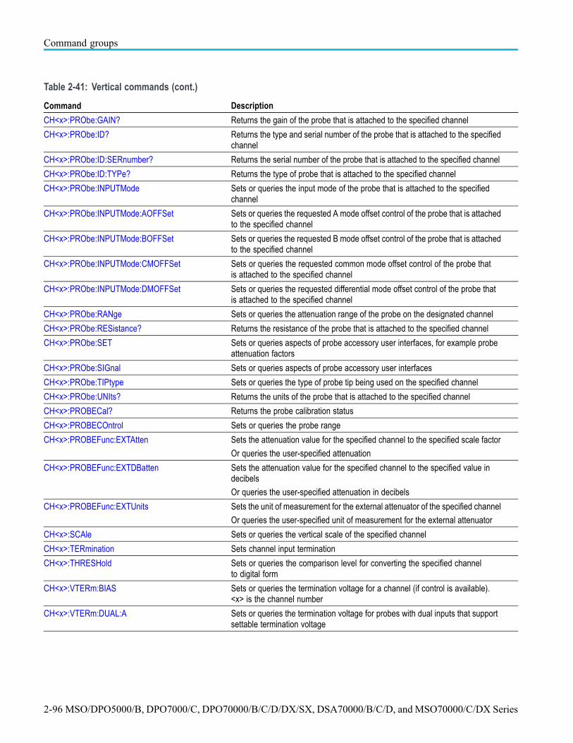
Command groups
Table 2-41: Vertical commands (cont.)
Command Description
CH<x>:PRObe:GAIN? Returns the gain of the probe that is attached to the specified channel
CH<x>:PRObe:ID? Returns the type and serial number of the probe that is attached to the specifiedchannel
CH<x>:PRObe:ID:SERnumber? Returns the serial number of the probe that is attached to the specified channel
CH<x>:PRObe:ID:TYPe? Returns the type of probe that is attached to the specified channel
CH<x>:PRObe:INPUTMode Sets or queries the input mode of the probe that is attached to the specifiedchannel
CH<x>:PRObe:INPUTMode:AOFFSet Sets or queries the requested A mode offset control of the probe that is attachedto the specified channel
CH<x>:PRObe:INPUTMode:BOFFSet Sets or queries the requested B mode offset control of the probe that is attachedto the specified channel
CH<x>:PRObe:INPUTMode:CMOFFSet Sets or queries the requested common mode offset control of the probe thatis attached to the specified channel
CH<x>:PRObe:INPUTMode:DMOFFSet Sets or queries the requested differential mode offset control of the probe thatis attached to the specified channel
CH<x>:PRObe:RANge Sets or queries the attenuation range of the probe on the designated channel
CH<x>:PRObe:RESistance? Returns the resistance of the probe that is attached to the specified channel
CH<x>:PRObe:SET Sets or queries aspects of probe accessory user interfaces, for example probeattenuation factors
CH<x>:PRObe:SIGnal Sets or queries aspects of probe accessory user interfaces
CH<x>:PRObe:TIPtype Sets or queries the type of probe tip being used on the specified channel
CH<x>:PRObe:UNIts? Returns the units of the probe that is attached to the specified channel
CH<x>:PROBECal? Returns the probe calibration status
CH<x>:PROBECOntrol Sets or queries the probe range
CH<x>:PROBEFunc:EXTAtten Sets the attenuation value for the specified channel to the specified scale factor
Or queries the user-specified attenuation
CH<x>:PROBEFunc:EXTDBatten Sets the attenuation value for the specified channel to the specified value indecibels
Or queries the user-specified attenuation in decibels
CH<x>:PROBEFunc:EXTUnits Sets the unit of measurement for the external attenuator of the specified channel
Or queries the user-specified unit of measurement for the external attenuator
CH<x>:SCAle Sets or queries the vertical scale of the specified channel
CH<x>:TERmination Sets channel input termination
CH<x>:THRESHold Sets or queries the comparison level for converting the specified channelto digital form
CH<x>:VTERm:BIAS Sets or queries the termination voltage for a channel (if control is available).<x> is the channel number
CH<x>:VTERm:DUAL:A Sets or queries the termination voltage for probes with dual inputs that supportsettable termination voltage
2-96 MSO/DPO5000/B, DPO7000/C, DPO70000/B/C/D/DX/SX, DSA70000/B/C/D, and MSO70000/C/DX Series

Command groups
Table 2-41: Vertical commands (cont.)
Command Description
CH<x>:VTERm:DUAL:B Sets or queries the termination voltage for probes with dual inputs that supportsettable termination voltage
REF<x>:HORizontal:POSition Sets or queries the horizontal position of the specified reference waveformin percent of the waveform that is displayed to the right of the center verticalgraticule
REF<x>:LABel? Returns a branch query containing the waveform label name and thecoordinates at which the label is displayed
REF<x>:LABel:NAMe Sets or queries the label of the designated waveform
REF<x>:LABel:XPOS Sets or queries the position of the reference waveform label on the X axis
REF<x>:LABel:YPOS Sets or queries the position of the reference waveform label on the Y axis
REF<x>:VERTical:POSition Sets or queries the vertical position of the specified reference waveform
REF<x>:VERTical:SCAle Sets or queries the reference waveform vertical scale in vertical units/div
SELect? Returns information on which waveforms are on or off and which waveform isselected
SELect:<wfm> Turns on the specified waveform
Or queries whether the specified channel is on or off
SELect:CH<x> Sets or queries the displayed state of the specified channel waveform
SELect:CONTROl Sets or queries the waveform controlled by the front panel
MSO/DPO5000/B, DPO7000/C, DPO70000/B/C/D/DX/SX, DSA70000/B/C/D, and MSO70000/C/DX Series 2-97

Command groups
Waveform Transfer command groupUse the commands in the Waveform Transfer Command Group to transferwaveform data points to and from the instrument. Waveform data points are acollection of values that define a waveform. One data value usually representsone data point in the waveform record. When working with envelope waveforms,each data value is either the minimum or maximum of a min/max pair.
Before you transfer waveform data, you must specify the data format, recordlength, and waveform source.
Data formats. Acquired waveform data uses eight or more bits to represent eachdata point. The number of bits used depends on the acquisition mode specifiedwhen you acquired the data. Data acquired in SAMple or ENVelope mode useseight bits per waveform data point. Data acquired in AVERage mode uses up to14 bits per point.
The instrument can transfer waveform data in either ASCII or binary format.You specify the format with the DATa:ENCdg command. The instrument usessigned, 4 byte integers and floating point values; it does not support unsignedfloating point values.
ASCII data is represented by signed integer or floating point values. An exampleASCII waveform data string can look like this:
CURVE<space>-110,-109,-110,-110,-109,-107,-109,-107,-106,-105,-103,-100,-97,-90,-84,-80
Use ASCII to obtain more readable and easier to format output than binary.However, ASCII can require more bytes to send the same values than it does withbinary. This can reduce transmission speeds.
Binary data can be represented by signed integer or floating point values. Therange of the values depends on the byte width specified. When the byte width isone, signed integer data ranges from -128 to 127, and positive integer valuesrange from 0 to 255. When the byte width is two, the values range from -32768 to32767. When a MATH (or REF that came from a MATH) is used, 32-bit floatingpoint values are used that are four bytes in width.
2-98 MSO/DPO5000/B, DPO7000/C, DPO70000/B/C/D/DX/SX, DSA70000/B/C/D, and MSO70000/C/DX Series

Command groups
The defined binary formats specify the order in which the bytes are transferred.The following are the four binary formats:
RIBinary specifies signed integer data-point representation with the mostsignificant byte transferred first.
SRIBinary is the same as RIBinary except that the byte order is swapped,meaning that the least significant byte is transferred first. This format is usefulwhen transferring data to PCs.
RFBinary specifies floating point data-point representation with the mostsignificant byte transferred first.
SRFBinary is the same as RFBinary except that the byte order is swapped,meaning that the least significant byte is transferred first. This format is usefulwhen transferring data to PCs.
Waveform data and record lengths. You can transfer multiple points for eachwaveform record. You can transfer a portion of the waveform or you can transferthe entire record. You can use the DATa:STARt and DATa:STOP commands tospecify the first and last data points of the waveform record.
When transferring data into the instrument, you must first specify the record lengthof the destination waveform record. You do this with the WFMInpre:NR_Ptcommand. Next, specify the first data point within the waveform record. Forexample, when you set DATa:STARt to 1, data points will be stored startingwith the first point in the record. The instrument will ignore the value set byDATa:STOP when reading in data. It will stop reading data when there is no moredata to read or when it has reached the specified record length.
The CURVe command cannot be used to transfer FastFrame waveforms intothe instrument.
When transferring data from the instrument, you must specify the first and lastdata points in the waveform record. Setting DATa:STARt to 1 and DATa:STOP tothe record length will always return the entire waveform.
For CURVe? queries of FastFrame acquisitions, the data for each frame isconcatenated together into one long stream. For example, if you acquire 5 framesof 1000 points each, a curve query (with DATA:START 1 and DATA:STOP 1000)will return 5 * 1000 or 5000 data points. There is no separator between eachframe in the data.
If you set DATA:START and DATA:STOP to a subset of the record length thenyou get that section of data from each frame. For example, with 5 frames of1000 points each and DATA:START 101 and DATA:STOP 150, you will getpoints 101-150 for the first frame followed by points 101-150 of the secondframe, and similar things. In this case the total number of points returned will be5 * 50 or 250 points.
Waveform data locations and memory allocation. The DATa:SOUrce commandspecifies the waveform source when transferring a waveform from the instrument.
MSO/DPO5000/B, DPO7000/C, DPO70000/B/C/D/DX/SX, DSA70000/B/C/D, and MSO70000/C/DX Series 2-99

Command groups
Waveforms sent to the instrument are always stored in one of the four referencememory locations. Use the DATa:DESTination command to specify a referencememory location.
Waveform preamble. Each waveform that you transfer has an associatedwaveform preamble that contains information such as the horizontal scale, thevertical scale, and other settings in effect when the waveform was created. Referto the individual WFMInpre? and WFMOutpre? commands for more information.
Scaling waveform data. Once you transfer the waveform data to the controller,you can convert the data points into voltage values for analysis using informationfrom the waveform preamble.
Transferring waveform data from the instrument.
You can transfer waveforms from the instrument to an external controller usingthe following sequence:
1. Select the waveform source(s) using DATa:SOUrce.
2. Specify the waveform data format using DATa:ENCdg.
3. Specify the number of bytes per data point using WFMOutpre:BYT_Nr.
NOTE. MATH waveforms (and REF waveforms that came from a MATH) arealways set to four bytes.
4. Specify the portion of the waveform that you want to transfer usingDATa:STARt and DATa:STOP.
5. Transfer waveform preamble information using WFMOutpre.
6. Transfer waveform data from the instrument using CURVe?.
Transferring waveform data to the instrument.
1. Specify waveform reference memory using DATa:DESTination.
2. Set WFMInpre:NR_Pt to equal the number of data points to be sent.
3. Specify the waveform data format using WFMInpre:ENCdg.
4. Specify the number of bytes per data point using WFMInpre:BYT_Nr.
5. Specify first data point in the waveform record using DATa:STARt.
6. Transfer waveform preamble information using WFMInpre.
7. Transfer the waveform data using CURVe.
NOTE. FastAcq and FastFrame waveforms cannot be returned to the instrumentvia the CURVe command
2-100 MSO/DPO5000/B, DPO7000/C,DPO70000/B/C/D/DX/SX, DSA70000/B/C/D, and MSO70000/C/DX Series

Command groups
Table 2-42: Waveform Transfer commands
Command Description
ALLOcate:WAVEform:REF<x>? Returns the record length for the specified reference waveform, if active, or zero(0) if not active
CURVe The command format transfers waveform data to the instrument (reference memorylocation specified by DATa:DESTination)
The query format transfers waveform data from instrument specified by theDATa:SOUrce command
CURVENext? Returns unique waveform data from a new acquisition
CURVEStream Transfers continuously the waveform data from the instrument as it is acquired
DATa Sets the format and location of the waveform data that is transferred with theCURVe Command
Or queries the format and location of the waveform data that is transferred withthe CURVe? command
DATa:DESTination Sets or queries the reference memory location for storing waveform data sent tothe instrument
DATa:ENCdg Sets or queries the format of outgoing waveform data
DATa:FRAMESTARt Sets or queries the starting data frame for waveform transfer
DATa:FRAMESTOP Sets or queries the ending data frame for waveform transfer
DATa:SOUrce Sets or queries the location of waveform data transferred from the instrument
DATa:STARt Sets or queries the starting point in waveform transfer
DATa:STOP Sets or queries the ending data point in waveform transfer
DATa:SYNCSOUrces Sets or queries if the data sync sources are on or off
WAVFrm? Returns WFMOutpre? and CURVe? data for the waveform as specified by theDATA:SOUrce command
WAVFRMStream? Returns WFMOUTPRE? and CURVESTREAM? data for the waveforms specified bythe DATASOURCE command
WFMInpre? Returns the waveform formatting specification to be applied to the next incomingCURVE command data
WFMInpre:BIT_Nr Sets or queries the number of bits per binary waveform point
WFMInpre:BN_Fmt Sets or queries the format of binary data for the incoming waveform
WFMInpre:BYT_Nr Sets or queries the binary field data width for the first ordered waveform
WFMInpre:BYT_Or Sets or queries the byte order of waveform points
WFMInpre:ENCdg Sets or queries the type of encoding for incoming waveform data
WFMInpre:NR_Pt Sets or queries the number of points in the transmitted waveform record
WFMInpre:NR_FR? This query returns the number of frames to be transferred to the instrument with theCurve command
WFMInpre:PT_Fmt Sets or queries the point format of incoming waveform data
WFMInpre:PT_Off Sets or queries the trigger point within the incoming waveform data
WFMInpre:WFId Allows a waveform extracted from the instrument to be more easily sent back
WFMInpre:XINcr Sets or queries the horizontal sampling interval between incoming waveform points
MSO/DPO5000/B, DPO7000/C, DPO70000/B/C/D/DX/SX, DSA70000/B/C/D, and MSO70000/C/DXSeries 2-101

Command groups
Table 2-42: Waveform Transfer commands (cont.)
Command Description
WFMInpre:XUNit Sets or queries the horizontal units of the incoming waveform
WFMInpre:XZEro Sets or queries the (sub-sample) time between the trigger sample and theoccurrence of the actual incoming waveform trigger
WFMInpre:YMUlt Sets or queries the vertical scale factor, per digitizing level, of the incomingwaveform points
WFMInpre:YOFf Sets or queries the vertical position of the incoming waveform in digitizing levels
WFMInpre:YUNit Sets or queries the vertical units of the incoming waveform
WFMInpre:YZEro Sets or queries the offset of the incoming waveform
WFMOutpre? Returns the waveform formatting data for the waveform specified by theDATA:SOURCE command
WFMOutpre:BIT_Nr Sets or queries the number of bits per waveform point that outgoing waveformscontain
WFMOutpre:BN_Fmt Sets or queries the format of binary data for the waveform
WFMOutpre:BYT_Nr Sets or queries the data width for the waveform
WFMOutpre:BYT_Or Sets or queries the byte order of waveform points
WFMOutpre:ENCdg Sets or queries the type of encoding for outgoing waveforms
WFMOutpre:NR_Pt? Returns the number of points for the waveform transmitted in response to aCURVe? query
WFMOutpre:NR_FR? Query-only command returns the number of frames for the DATa:SOUrce waveformtransmitted in response to a CURVe? query
WFMOutpre:PT_Fmt? Returns the point format for the waveform
WFMOutpre:PT_Off? Returns the trigger point relative to DATA:START for the waveform
WFMOutpre:PT_ORder? Returns whether the source waveform is DPO
WFMOutpre:WFId? Returns a string describing the acquisition parameters for the waveform
WFMOutpre:XINcr? Returns the horizontal sampling interval
WFMOutpre:XUNit? Returns the horizontal units for the waveform
WFMOutpre:XZEro? Returns the (sub-sample) time between the trigger sample and the occurrenceof the actual waveform trigger
WFMOutpre:YMUlt? Returns the vertical scale factor per digitizing level for the waveform
WFMOutpre:YOFf? Returns the vertical offset in digitizing levels for the waveform
WFMOutpre:YUNit? Returns the vertical units for the waveform
WFMOutpre:YZEro? Returns the vertical offset for the waveform
2-102 MSO/DPO5000/B, DPO7000/C,DPO70000/B/C/D/DX/SX, DSA70000/B/C/D, and MSO70000/C/DX Series

Command groups
Zoom command groupZoom commands let you expand and position the waveform display horizontallyand vertically, without changing the time base or vertical settings.
You can specify up to four zoom areas. You can also specify a zoomed waveformas a zoom source, which enables you to zoom in on a zoomed waveform.
Table 2-43: Zoom commands
Command Description
ZOOm Resets the zoom transforms to default values for all traces or live traces. The ZOOmquery returns the current vertical and horizontal positioning and scaling of the display
ZOOm:GRAticule:SIZE Sets or queries the size of the zoom graticule
ZOOm:HORizontal:POSition Sets or queries the horizontal position around which the zoom waveform isdisplayed. It is freely movable within the confines of the acquired waveform (0% to100%) and measured from left to right of the acquired waveform
ZOOm:HORizontal:SCAle Sets or queries the zoom horizontal scale factor around which the zoom waveform isdisplayed
ZOOm:MATH<x>:HORizontal:POSition Sets or queries the horizontal position of the specified math waveform
ZOOm:MATH<x>:HORizontal:SCAle Sets or queries the zoom horizontal scale factor of the specified math waveform
ZOOm:MATH<x>:VERTical:POSition Sets or queries the vertical position of the specified math waveform
ZOOm:MATH<x>:VERTical:SCAle Sets or queries the vertical scale of the specified math waveform
ZOOm:MODe Sets or queries the zoom mode
ZOOm:REF<x>:HORizontal:POSition Sets or queries the horizontal position of the specified reference waveform
ZOOm:REF<x>:HORizontal:SCAle Sets or queries the zoom horizontal scale factor of the specified reference waveform
ZOOm:REF<x>:VERTical:POSition Sets or queries the vertical position of the specified reference waveform
ZOOm:REF<x>:VERTical:SCAle Sets or queries the zoom vertical scale of the specified reference waveform
ZOOm:SCROLL:DIREction Sets or queries the direction of AutoScroll for zoomed waveforms
ZOOm:SCROLL:LOCk Sets or queries the state of Scroll Lock, on or off
ZOOm:SCROLL:SPEED Sets or queries the speed of AutoScroll for zoomed waveforms
ZOOm:STATE Specifies or returns a trace as zoomed on or off
ZOOm:VERTical:POSition Sets or queries the vertical position around which the zoom waveform is displayed.It is freely movable within the confines of the acquired waveform (0% to 100%) andmeasured from left to right of the acquired waveform
ZOOm:VERTical:SCAle Sets or queries the zoom vertical scale factor around which the zoom waveform isdisplayed
ZOOm:ZOOM<x> Sets or queries zoom factors for the specified zoom
ZOOm:ZOOM<x>:DCHAN:DISplay Sets or queries the display of the digital waveforms for the specified zoom
ZOOm:ZOOM<x>:SCROLLLock Sets or queries Scroll Lock for the specified zoom
ZOOm:ZOOM<x>:STATE Sets or queries the specified zoom on or off, where x is an integer from 1 to 4representing the desired zoom window
ZOOm:ZOOM<x>:<wfm>:DISplay Sets or queries the display of the specified waveform for the specified zoom
MSO/DPO5000/B, DPO7000/C, DPO70000/B/C/D/DX/SX, DSA70000/B/C/D, and MSO70000/C/DXSeries 2-103

Command groups
Table 2-43: Zoom commands (cont.)
Command Description
ZOOm:ZOOM<x>:<wfm>:HORizontal:POSition
Sets or queries the horizontal position of the specified waveform for the specifiedzoom
ZOOm:ZOOM<x>:<wfm>:HORizontal:SCAle Sets or queries the horizontal zoom scale of the specified waveform in the specifiedzoom
ZOOm:ZOOM<x>:<wfm>:VERTical:POSition Sets or queries the vertical zoom position for the specified waveform in the specifiedzoom
ZOOm:ZOOM<x>:<wfm>:VERTical:SCAle Sets or queries the vertical zoom scale for the specified waveform in the specifiedzoom
2-104 MSO/DPO5000/B, DPO7000/C,DPO70000/B/C/D/DX/SX, DSA70000/B/C/D, and MSO70000/C/DX Series

Commands listed in alphabetical orderNOTE. Some of the following commands may not be available on your instrumentmodel. Also, some of the following commands are only available if yourinstrument has the associated option installed.
ACQuire:ENHANCEDEnobThis command sets or queries the state of the enhanced effective number of bits.
Group Acquisition
Syntax ACQuire:ENHANCEDEnob {OFF|AUTO}
Arguments OFF turns off enhanced effective number of bits.
AUTO turns enhanced effective number of bits to AUTO.
Examples ACQUIRE:ENHANCEDENOB AUTO sets enhanced effective number of bits to AUTO.
ACQuire:ENHANCEDEnob:STATE? (Query Only)This command queries the state of the enhanced effective number of bits.
Group Acquisition
Syntax ACQuire:ENHANCEDEnob:STATE?
Returns 0 indicates that the enhanced effective number of bits in not on.
1 indicates that the enhanced effective number of bits in on.
Examples ACQUIRE:ENHANCEDENOB:STATE? might return:ACQUIRE:ENHANCEDENOB:STATE 0 indicating that enhanced effective numberof bits in not on.
ACQuire:INTERPEightbitThis command sets or queries the interpolation acquisition mode of the instrument.
MSO/DPO5000/B, DPO7000/C, DPO70000/B/C/D/DX/SX, DSA70000/B/C/D, and MSO70000/C/DXSeries 2-105
Commands listed in alphabetical order
Group Acquisition
Syntax ACQuire:INTERPEightbit {AUTO|ON|OFF}ACQuire:INTERPEightbit?
Arguments AUTO lets the instrument automatically select the interpolation acquisition mode.
ON turns on the eight bit interpolation mode.
OFF turns off the eight bit interpolation mode.
Examples ACQUIRE:INTERPEIGHTBIT ON sets the interpolation sampling mode On.
ACQUIRE:INTERPEIGHTBIT? might return :ACQUIRE:INTERPEIGHTBITAUTO indicating the interpolation sampling mode is set to Auto.
ACQuire:MAGnivu
NOTE. Not available on some models.
This command sets or queries the MagniVu feature.
This feature provides up to 32 times signal detail for fast viewing of short eventsand is not recommended for slow data formats such as RS-232.
Group Acquisition
Syntax ACQuire:MAGnivu {<NR1>|OFF|ON}ACQuire:MAGnivu?
Arguments <NR1> = 0 disables the MagniVu feature; any other value turns this feature on.
OFF disables the MagniVu feature.
ON enables the MagniVu feature.
Examples ACQUIRE:MAGNIVU ON sets the MagniVu mode to On.
ACQUIRE:MAGNIVU? might return :ACQUIRE:MAGNIVU ON, indicating that theMagniVu mode is On.
2-106 MSO/DPO5000/B, DPO7000/C,DPO70000/B/C/D/DX/SX, DSA70000/B/C/D, and MSO70000/C/DX Series

Commands listed in alphabetical order
ACQuire:MODeThis command sets or queries the selected acquisition mode of the instrument.This affects all live waveforms. This command is equivalent to selectingHorizontal/Acquisition from the Horiz/Acq menu, and then choosing the desiredmode from the Acquisition Mode group box. ACQuire:MODe is the desiredacquisition mode.
Waveforms are the displayed data point values taken from acquisition intervals.Each acquisition interval represents a time duration set by the horizontal scale(time per division). The instrument sampling system always samples at themaximum rate and so an acquisition interval can include more than one sample.
The acquisition mode (which you set using this ACQuire:MODe command)determines how the final value of the acquisition interval is generated from themany data samples.
NOTE. In cases when either HIRes or PkDetect is the selected mode, and thesampling rate is greater than or equal to the base sampling rate (that is 6.25 Gs/sfor 70K oscilloscopes and 5 Gs/s for 5K and 7K oscilloscopes), neither HIRes norPkDetect mode is available for the instrument to actually use. Sample mode isused instead, regardless of the mode setting. To determine which mode is actuallyused in these cases, use the query ACQuire:MODe:ACTUal?
Group Acquisition
Syntax ACQuire:MODe{SAMple|PEAKdetect|HIRes|AVErage|WFMDB|ENVelope}ACQuire:MODe?
Related Commands ACQuire:NUMAVg, CURVe, ACQuire:MODe:ACTUal?
Arguments SAMple specifies that the displayed data point value is the first sampled valuethat is taken during the acquisition interval. In sample mode, all waveform datahas 8 bits of precision. You can request 16 bit data with a CURVe query but thelower-order 8 bits of data will be zero. SAMple is the default mode.
PEAKdetect specifies the display of high-low range of the samples taken from asingle waveform acquisition. The high-low range is displayed as a vertical columnthat extends from the highest to the lowest value sampled during the acquisitioninterval. PEAKdetect mode can reveal the presence of aliasing or narrow spikes.
HIRes specifies Hi Res mode where the displayed data point value is theaverage of all the samples taken during the acquisition interval. This is a formof averaging, where the average comes from a single waveform acquisition. The
MSO/DPO5000/B, DPO7000/C, DPO70000/B/C/D/DX/SX, DSA70000/B/C/D, and MSO70000/C/DXSeries 2-107

Commands listed in alphabetical order
number of samples taken during the acquisition interval determines the number ofdata values that compose the average.
AVErage specifies averaging mode, in which the resulting waveform shows anaverage of SAMple data points from several separate waveform acquisitions. Theinstrument processes the number of waveforms you specify into the acquiredwaveform, creating a running exponential average of the input signal. The numberof waveform acquisitions that go into making up the average waveform is set orqueried using the ACQuire:NUMEnv command.
WFMDB (Waveform Database) mode acquires and displays a waveform pixmap. Apixmap is the accumulation of one or more acquisitions.
ENVelope specifies envelope mode, where the resulting waveform shows thePEAKdetect range of data points from several separate waveform acquisitions.The number of waveform acquisitions that go into making up the envelopewaveform is set or queried using the ACQuire:NUMEnv command.
The instrument acquires data after each trigger event using Sample mode; it thendetermines the pix map location of each sample point and accumulates it withstored data from previous acquisitions.
A Pix map is a two dimensional array. The value at each point in the array isa counter that reflects the hit intensity. Infinite and noninfinite persist displaymodes affect how pix maps are accumulated. Zoom, Math, FastAcq, FastFrame,XY, Roll, and Interpolated Time (IT) Sampling Mode are conflicting features toWFMDB acqMode. Turning on one of them generally turns the other one off.Selection of some standard masks (for example, eye masks, which require optionMTM) changes the acquisition mode to WFMDB.
Examples ACQUIRE:MODE ENVELOPE sets the acquisition mode to display a waveform thatis an envelope of many individual waveform acquisitions.
ACQUIRE:MODE? might return :ACQuire:MODe AVERAGE, indicating thatthe displayed waveform is the average of the specified number of waveformacquisitions.
ACQuire:MODe:ACTUal? (Query Only)This query returns the acquisition mode that the instrument is actually using foracquisitions, as opposed to the ACQuire:MODe query, which returns the currentlyselected acquisition mode. The acquisition mode that the instrument is using maydiffer from the selected mode in cases where the HIRes or PkDetect mode hasbeen selected and the sample rate is greater than or equal to the base sampling rate(that is 6.25 Gs/s for 70K oscilloscopes and 5 Gs/s for 5K and 7K oscilloscopes).This is because the HIRes and PkDetect modes are not available at such highsampling rates. In these cases, the instrument uses sampling mode, and this queryreturns SAMPLe, regardless of the mode selected.
2-108 MSO/DPO5000/B, DPO7000/C,DPO70000/B/C/D/DX/SX, DSA70000/B/C/D, and MSO70000/C/DX Series

Commands listed in alphabetical order
In other words, when either HIRes or PkDetect mode has been selected, and thesample rate is greater than or equal to the base sampling rate (that is 6.25 Gs/s for70K scopes and 5 Gs/s for 5K and 7K oscilloscopes), use the ACQuire:MODequery to determine the current mode selection; use ACQuire:MODe:ACTUal?to determine which mode the instrument is actually using. For other modes, useeither query, as they will return the same mode.
Group Acquisition
Syntax ACQuire:MODe:ACTUal?
Related Commands ACQuire:MODe
Examples ACQUIRE:MODE:ACTUAL? might return the following:
In cases where the sampling rate ≥6.25 Gs/s for 70K oscilloscopes and 5 Gs/s for5K and 7K oscilloscopes, and HIRes or PkDetect is the currently selected mode,then ACQuire:MODe:ACTUal? will return SAMPLE.
In cases where the sampling rate < 6.25 Gs/s for 70K oscilloscopes and 5 Gs/sfor 5K and 7K oscilloscopes, and HIRes or PkDetect is the currently selectedmode, then ACQuire:MODe:ACTUal? will return either HI RESOLUTION orPEAK DETECT.
In cases where one of the other modes has been selected (that is AVErage,WFMDB or ENVelope), then ACQuire:MODe:ACTUal? will return AVERAGE,WFMDB or ENVELOPE.
ACQuire:NUMACq? (Query Only)This query-only command returns the number of waveform acquisitions that haveoccurred since starting acquisition with the ACQuire:STATE RUN command.This value is reset to zero when any acquisition, horizontal, or vertical argumentsthat affect the waveform are changed. The maximum number of acquisitions thatcan be counted is 230–1. The instrument stops counting when this number isreached. This is the same value that displays in the lower right of the screen.
Group Acquisition
Syntax ACQuire:NUMACq?
Related Commands ACQuire:STATE
MSO/DPO5000/B, DPO7000/C, DPO70000/B/C/D/DX/SX, DSA70000/B/C/D, and MSO70000/C/DXSeries 2-109

Commands listed in alphabetical order
Examples ACQUIRE:NUMACQ? might return :ACQUIRE:NUMACQ 350, indicating that 350acquisitions have occurred since executing an ACQuire:STATE RUN command.
ACQuire:NUMAVgThis command sets or queries the number of waveform acquisitions that make upan averaged waveform. Use the ACQuire:MODe command to enable the Averagemode. Sending this command is equivalent to selecting Horizontal/AcquisitionSetup from the Horiz/Acq menu, selecting the Acquisition tab, and choosingAverage from the Acquisition Mode group box. Then enter the desired numberof waveforms that will be used to make up an averaged waveform in the # ofWfms box.
Group Acquisition
Syntax ACQuire:NUMAVg <NR1>ACQuire:NUMAVg?
Related Commands ACQuire:MODe
Arguments <NR1> is the number of waveform acquisitions to average.
Examples ACQUIRE:NUMAVG 10 specifies that 10 waveform averages will be performedbefore exponential averaging starts.
ACQUIRE:NUMAVG? might return :ACQUIRE:NUMAVG 75, indicating that thereare 75 acquisitions specified for averaging.
ACQuire:NUMEnvThis command sets or queries the number of waveform acquisitions that makeup an envelope waveform. Sending this command is equivalent to setting the #of Wfms in the Acquisition Setup menu when Envelope Acquisition mode isselected.
NOTE. Sending INFInite as an argument sets 2e9 envelopes. The query responsewill be 2e9 not INFInite.
Group Acquisition
2-110 MSO/DPO5000/B, DPO7000/C,DPO70000/B/C/D/DX/SX, DSA70000/B/C/D, and MSO70000/C/DX Series

Commands listed in alphabetical order
Syntax ACQuire:NUMEnv {<NR1>|INFInite}ACQuire:NUMEnv?
Arguments <NR1> is the number of waveform acquisitions to be enveloped.
INFInite specifies the number of waveform acquisitions to be enveloped.Setting the argument to infinite sets the envelopes to 2e9.
Examples ACQUIRE:NUMENV 10 specifies that an enveloped waveform will show the resultof combining 10 separately acquired waveforms.
ACQUIRE:NUMENV? might return :ACQUIRE:NUMENV 75, indicating that 75acquisitions are acquired for enveloped waveforms.
ACQuire:NUMFRAMESACQuired? (Query Only)This query-only command returns the number of frames acquired when inFastFrame Single Sequence and acquisitions are running. When the FastFramesingle sequence stop condition is set to Stop Manually, this number counts pastthe number of frames which were requested as new frames are acquired, untilSTOP is pushed. When not in FastFrame Single Sequence, this value is the samenumber reported by ACQ:NUMACQ.
Group Acquisition
Syntax ACQuire:NUMFRAMESACQuired?
Related Commands ACQuire:NUMACq?
Examples ACQUIRE:NUMFRAMESACQUIRED? might return:ACQUIRE:NUMFRAMESACQUIRED 350, indicating that 350 frames have beenacquired.
ACQuire:NUMSAMplesThis command sets or queries the minimum number of acquired samples thatmake up a waveform database (WfmDB) waveform for single sequence mode andMask Pass/Fail Completion Test. This is equivalent to setting the WaveformDatabase Samples in the Acquisition Mode side menu.
Group Acquisition
MSO/DPO5000/B, DPO7000/C, DPO70000/B/C/D/DX/SX, DSA70000/B/C/D, and MSO70000/C/DXSeries 2-111

Commands listed in alphabetical order
Syntax ACQuire:NUMSAMples <NR1>ACQuire:NUMSAMples?
Arguments <NR1> is the minimum number of acquired samples that make up a waveformdatabase (WfmDB) waveform for single sequence mode and Mask Pass/FailCompletion Test. The default value is 16,000 samples. The range is 5,000 to2,147,400,000 samples.
In real time mode, if the entire trace is displayed, one triggered acquisition shouldacquire 5000 samples for a record length of 5000. If you want 5001 samples, theinstrument will need to make two acquisitions (10,000 samples). If you requestfewer samples than the record length, the number of samples will be the same asthe record length.
Examples ACQUIRE:NUMSAMPLES 5000 specifies that 5000 samples will be acquired inWfmDB mode for single sequence mode and Mask Pass/Fail Completion Test.
ACQUIRE:NUMSAMPLES? might return :ACQUIRE:NUMSAMples 10000,indicating that there are 10,000 samples to be acquired in WfmDB mode forsingle sequence and Mask Pass/Fail Completion Test.
ACQuire:SAMPlingmodeThis command sets or queries the sampling mode.
Group Acquisition
Syntax ACQuire:SAMPlingmode {RT|ET|IT}ACQuire:SAMPlingmode?
Arguments RT sets the sampling mode to real time only.
ET sets the sampling mode to equivalent time allowed (ON in REPET).
IT sets the sampling mode to interpolation allowed (OFF in REPET).
The number of channels selected and the sampling speed affects the mode thatthe instrument uses to acquire data. At slow sampling speeds the instrument usesreal time sampling. At fast sampling speeds, the instrument uses equivalent timesampling or interpolation. For speeds between these extremes, some instrumentscreate waveform records differently, depending on the number of input channelsselected.
2-112 MSO/DPO5000/B, DPO7000/C,DPO70000/B/C/D/DX/SX, DSA70000/B/C/D, and MSO70000/C/DX Series

Commands listed in alphabetical order
Examples ACQUIRE:SAMPLINGMODE IT specifies that interpolation is allowed.
ACQUIRE:SAMPLINGMODE? might return :ACQUIRE:SAMPLINGMODE RT,indicating that sampling mode is real time only.
ACQuire:STATEThis command starts or stops acquisitions. When state is set to ON or RUN, anew acquisition will be started. If the last acquisition was a single acquisitionsequence, a new single sequence acquisition will be started. If the last acquisitionwas continuous, a new continuous acquisition will be started.
If RUN is issued in the middle of completing a single sequence acquisition (forexample, averaging or enveloping), the acquisition sequence is restarted, andany accumulated data is discarded. Also, the instrument resets the number ofacquisitions. If the RUN argument is issued while in continuous mode, a resetoccurs and acquired data continues to acquire.
If acquire:stopafter is SEQUENCE, pressing the front panel RUN/STOP button isequivalent to sending these commands: ACQUIRE:STOPAFTER RUNSTOP andeither ACQUIRE:STATE ON or ACQUIRE:STATE RUN.
Group Acquisition
Syntax ACQuire:STATE {<NR1>|OFF|ON|RUN|STOP}ACQuire:STATE?
Related Commands ACQuire:STOPAfter
Arguments <NR1> = 0 stops acquisitions; any other value starts acquisitions.
OFF stops acquisitions.
ON starts acquisitions.
RUN starts acquisitions.
STOP stops acquisitions.
Examples ACQUIRE:STATE RUN starts the acquisition of waveform data and resets the countof the number of acquisitions.
ACQUIRE:STATE? might return :ACQUIRE:STATE 0, indicating that theacquisition is stopped.
MSO/DPO5000/B, DPO7000/C, DPO70000/B/C/D/DX/SX, DSA70000/B/C/D, and MSO70000/C/DXSeries 2-113

Commands listed in alphabetical order
ACQuire:STOPAfterThis command sets or queries whether the instrument continually acquiresacquisitions or acquires a single sequence. Pressing SINGLE on the frontpanel button is equivalent to sending these commands: ACQUIRE:STOPAFTERSEQUENCE and ACQUIRE:STATE 1.
Group Acquisition
Syntax ACQuire:STOPAfter {RUNSTop|SEQuence}ACQuire:STOPAfter?
Related Commands ACQuire:STATE
Arguments RUNSTop specifies that the instrument will continually acquire data, ifACQuire:STATE is turned on.
SEQuence specifies that the next acquisition will be a single-sequence acquisition.
Examples ACQUIRE:STOPAFTER RUNSTOP sets the instrument to continually acquire data.
ACQUIRE:STOPAFTER? might return :ACQUIRE:STOPAFTER SEQUENCE,indicating that the next acquisition the instrument makes will be of thesingle-sequence type.
ALIasThis command sets or queries the state of alias functionality.
Group Alias
Syntax ALIas {OFF|ON|<NR1>}ALIas?
Related Commands ALIas:STATE
Arguments OFF turns Alias expansion off. If a defined alias is sent when ALIas:STATE isoff, a command error (102) will be generated.
ON turns Alias expansion on. When a defined alias is received, the specifiedcommand sequence is substituted for the alias and executed.
2-114 MSO/DPO5000/B, DPO7000/C,DPO70000/B/C/D/DX/SX, DSA70000/B/C/D, and MSO70000/C/DX Series

Commands listed in alphabetical order
<NR1> = 0 disables Alias mode; any other value enables Alias mode.
Examples ALIAS ON turns the alias feature on. When a defined alias is received, the specifiedcommand sequence is substituted for the alias and executed.
ALIAS? might return :ALIAS:STATE 1, indicating that the alias feature is on.
ALIas:CATalog? (Query Only)This query-only command returns a list of the currently defined alias labels,separated by commas. If no aliases are defined, the query returns the string “”.
Group Alias
Syntax ALIas:CATalog?
Examples ALIAS:CATALOG? might return the string :ALIAS:CATALOG
"SETUP1","TESTMENU1","DEFAULT" showing that there are three aliasesnamed SETUP1, TESTMENU1, and DEFAULT.
ALIas:DEFineThis command assigns a sequence of program messages to an alias label. Thesemessages are then substituted for the alias whenever it is received as a commandor query, provided that ALIas:STATE is turned on. The query form of thiscommand returns the definitions of a selected alias.
NOTE. Attempting to give two aliases the same name causes an error. To give anew alias the name of an existing alias, the existing alias must first be deleted.
Group Alias
Syntax ALIas:DEFine <QString><,>{<QString>|<Block>}ALIas:DEFine?
Related Commands ALIas:STATE
MSO/DPO5000/B, DPO7000/C, DPO70000/B/C/D/DX/SX, DSA70000/B/C/D, and MSO70000/C/DXSeries 2-115
Commands listed in alphabetical order
Arguments The first <QString> is the alias label.
This label cannot be a command name. Labels must start with a letter and cancontain only letters, numbers, and underscores; other characters are not allowed.The label must be less than or equal to 12 characters.
The second <QString> or <Block> is a complete sequence of program messages.
The messages can contain only valid commands that must be separated bysemicolons and must follow all rules for concatenating commands. The sequencemust be less than or equal to 256 characters.
Examples ALIAS:DEFINE "ST1",":RECALL:SETUP 5;:AUTOSET
EXECUTE;:SELECT:CH1 ON" defines an alias named “ST1” that setsup the instrument.
ALIAS:DEFINE? "ST1" returns :ALIAS:DEFINE "ST1",#246
:RECALL:SETUP 5;:AUTOSET EXECUTE;:SELECT:CH1 ON.
ALIas:DELEte (No Query Form)This command removes a specified alias and is identical to ALIas:DELEte:NAMe.An error message is generated if the named alias does not exist.
Group Alias
Syntax ALIas:DELEte <QString>
Related Commands *ESR?, ALIas:DELEte:ALL
Arguments <QString> is the name of the alias to be removed. Using ALIas:DELEtewithout specifying an alias causes an execution error. <QString> must be apreviously defined value.
Examples ALIAS:DELETE "SETUP1" deletes the alias named SETUP1.
ALIas:DELEte:ALL (No Query Form)This command deletes all existing aliases.
Group Alias
2-116 MSO/DPO5000/B, DPO7000/C,DPO70000/B/C/D/DX/SX, DSA70000/B/C/D, and MSO70000/C/DX Series

Commands listed in alphabetical order
Syntax ALIas:DELEte:ALL
Related Commands ALIas:DELEte, ALIas:DELEte:NAMe
Examples ALIAS:DELETE:ALL deletes all existing aliases.
ALIas:DELEte:NAMe (No Query Form)This command removes a specified alias. An error message is generated if thenamed alias does not exist. This command is identical to ALIas:DELEte.
Group Alias
Syntax ALIas:DELEte:NAMe <QString>
Arguments <QString> is the name of the alias to remove. Using ALIas:DELEte:NAMewithout specifying an alias causes an exception error.<QString> must be apreviously defined alias.
Examples ALIAS:DELETE:NAME "STARTUP" deletes the alias named STARTUP.
ALIas:STATEThis command turns aliases on or off and is identical to the ALIas command. Thequery form of this command returns the state of the aliases.
Group Alias
Syntax ALIas:STATE {<NR1>|OFF|ON}ALIas:STATE?
Arguments <NR1> = 0 turns off aliases; any other value turns on aliases.
OFF turns alias expansion off. If a defined alias is sent when ALIas:STATE isOFF, the instrument generates a command error (102).
ON turns alias expansion on. When a defined alias is received, the specifiedcommand sequence is substituted for the alias and executed.
MSO/DPO5000/B, DPO7000/C, DPO70000/B/C/D/DX/SX, DSA70000/B/C/D, and MSO70000/C/DXSeries 2-117

Commands listed in alphabetical order
Examples ALIAS:STATE OFF turns off the alias feature.
ALIAS:STATE? might return :ALIAS:STATE ON, indicating that alias expansionis currently turned on.
ALLEv? (Query Only)This query-only command prompts the instrument to return all events and theirmessages (delimited by commas), and removes the returned events from the EventQueue. Use the *ESR? query to enable the events to be returned. This commandis similar to repeatedly sending *EVMsg? queries to the instrument.
Group Status and Error
Syntax ALLEv?
Related Commands *ESR?, EVMsg?
Examples ALLEV? might return :ALLEV 2225,"Measurement error, No waveform
to measure; "420,"Query UNTERMINATED;".
ALLOcate:WAVEform:REF<x>? (Query Only)This query-only command returns the record length for the specified referencewaveform, if active, or zero (0) if not active (that is, no slot exists for the referencewaveform).
Group Waveform Transfer
Syntax ALLOcate:WAVEform:REF<x>?
Examples ALLOCATE:WAVEFORM:REF3? might return 5000 if a 5000 point waveform wasactive in the reference 3 slot.
APPLication:ACTivate (No Query Form)For legacy Java based applications, starts the application specified in the string.The available applications depend on the oscilloscope model and installedoptions. (DPOJET and DPOJET-based applications do not require this command
2-118 MSO/DPO5000/B, DPO7000/C,DPO70000/B/C/D/DX/SX, DSA70000/B/C/D, and MSO70000/C/DX Series

Commands listed in alphabetical order
and are started automatically by sending them any command, such as DPOJET:VERsion?)
Group Miscellaneous
Syntax APPLication:ACTivate <string>
Related Commands APPLication:SCOPEAPP:WINDOW
Arguments <string> is the name of the application that you want to start. Enter theapplication name exactly as it appears in the oscilloscope Analyze menu.
Examples APPLICATION:ACTIVATE “PCI Express” starts the PCI Express application.
APPLication:SCOPEAPP:WINDOWSets or queries whether the oscilloscope application is minimized or displayedfull screen.
Group Miscellaneous
Syntax APPLication:SCOPEAPP:WINDOW {FULLSCREEN|MINIMIZED}APPLication:SCOPEAPP:WINDOW?
Related Commands APPLication:ACTivate
Arguments FULLSCREEN sets the oscilloscope display to fill the oscilloscope screen.
MINIMIZED minimizes the oscilloscope display to an icon at the bottom of thescreen.
Examples APPLICATION:SCOPEAPP:WINDOW FULLSCREEN causes the oscilloscopedisplay to fill the oscilloscope screen.
APPLICATION:SCOPEAPP:WINDOW? might return:APPLICATION:SCOPEAPP:WINDOW MINIMIZED, indicating that theoscilloscope display has been minimized.
MSO/DPO5000/B, DPO7000/C, DPO70000/B/C/D/DX/SX, DSA70000/B/C/D, and MSO70000/C/DXSeries 2-119

Commands listed in alphabetical order
AUTOSet (No Query Form)This command (no query format) sets the vertical, horizontal, and trigger controlsof the instrument to automatically acquire and display the selected waveform.(To autoset a video waveform, the video trigger must be set to video standard,not custom. Video arguments require video hardware.) This is equivalent topressing the front panel AUTOSET button. For a detailed description of autosetfunctionality, see Autoset in the index of the online help for your instrument.
Group Miscellaneous
Syntax AUTOSet {EXECute|UNDo|VFields|VIDeo|VLines}
Related Commands DISplay:GRAticule
Arguments EXECute autosets the displayed waveform; this is equivalent to pressing the frontpanel AUTOSET button. If the display is set to a PAL, MV, or IRE graticule, thisargument forces the graticule display to full mode (frame, grid, and cross hair).
UNDo returns the instrument to the setting prior to executing an autoset.
VFields autosets the displayed waveform.
VIDeo autosets the displayed waveform.
VLines autosets the displayed waveform.
Examples AUTOSET VFields sets the instrument to trigger on all video fields.
AUXIn:BANdwidthThis command sets or queries the selectable low-pass bandwidth limit filter of theAUX In input. The bandwidth will change with an appropriate probe attached.This is equivalent to selecting Bandwidth from the Vertical menu.
The query form of this command always returns the maximum bandwidth ofthe AUX In input.
Group Vertical
Syntax AUXIn:BANdwidth <NR3>AUXIn:BANdwidth?
2-120 MSO/DPO5000/B, DPO7000/C,DPO70000/B/C/D/DX/SX, DSA70000/B/C/D, and MSO70000/C/DX Series

Commands listed in alphabetical order
Arguments <NR3> is one of the supported bandwidths on the attached probe.
Examples AUXIN:BANDWIDTH 10.0000E+9 sets the bandwidth of AUX In input to10 GHz.
AUXIN:BANDWIDTH?, for DPO7054 instruments, might return:AUXIN:BANDWIDTH 500.0000E+06, indicating that there is no bandwidthlimiting on the AUX In input.
AUXIn:COUPlingThis command sets or queries the input attenuator coupling setting for the AUXIn input. The coupling will change with an appropriate probe attached. Thiscommand is equivalent to selecting Coupling from the Vertical menu.
Group Vertical
Syntax AUXIn:COUPling <NR3>AUXIn:COUPling?
Arguments <NR3> is one of the supported input attenuator couplings on the attached probe.
Examples AUXIN:COUPLING GND sets the AUX In input to ground.
AUXIN:COUPling? might return :AUXIN:COUPling GND, indicating that AUXIn input is set to GND coupling.
AUXIn:OFFSetThis command sets or queries the vertical offset for the AUX In input. Thiscommand is equivalent to selecting Offset from the Vertical menu.
This command offsets the vertical acquisition window (moves the level at thevertical center of the acquisition window) for the input. Visualize offset asscrolling the acquisition window towards the top of a large signal for increasedoffset values, and scrolling towards the bottom for decreased offset values. Theresolution of the vertical window sets the offset increment for this control.
Offset adjusts only the vertical center of the acquisition window to help determinewhat data is acquired. The instrument always displays the input signal minus theoffset value. The channel reference marker will move to the vertical graticuleposition given by the negative of the offset value divided by the scale factor,unless that position is off-screen. If the computed coordinate for the reference
MSO/DPO5000/B, DPO7000/C, DPO70000/B/C/D/DX/SX, DSA70000/B/C/D, and MSO70000/C/DXSeries 2-121

Commands listed in alphabetical order
mark is off-screen, the mark moves to the nearest screen limit and changes froma right-pointing arrow ( →) to an arrow pointing in the appropriate off-screendirection.
Group Vertical
Syntax AUXIn:OFFSet <NR3>AUXIn:OFFSet?
Arguments <NR3> is the offset value for the specified channel.
Examples AUXIN:OFFSet 2.0E-3 sets the offset for AUX In input to 2 mV.
AUXIN:OFFSet? might return :AUXIN:OFFSET 1.0000E-03, indicating thatthe offset for AUX In input is set to 1 mV.
AUXIn:PRObe:AUTOZero (No Query Form)The command sets the probe attached to the AUX In input to autozero.
Group Vertical
Syntax AUXIn:PRObe:AUTOZero EXECute
Arguments EXECute sets the probe to autozero.
Examples AUXIN:PROBE:AUTOZERO EXECUTE sets the probe to autozero.
AUXIn:PRObe:DEGAUSS (No Query Form)This command starts a degauss cycle of the probe attached to the AUX In input.The degauss cycle will change with an appropriate probe attached.
Group Vertical
Syntax AUXIn:PRObe:DEGAUSS EXECute
2-122 MSO/DPO5000/B, DPO7000/C,DPO70000/B/C/D/DX/SX, DSA70000/B/C/D, and MSO70000/C/DX Series

Commands listed in alphabetical order
Arguments EXECute starts a probe degauss cycle.
Examples AUXIN:PROBE:DEGAUSS EXECUTE, degausses the probe attached to the AUXIn input.
AUXIn:PRObe:DEGAUSS:STATE? (Query Only)This command queries whether the probe attached to the AUX In input isdegaussed.
Group Vertical
Syntax AUXIn:PRObe:DEGAUSS:STATE?
Examples AUXIN:PROBE:DEGAUSS:STATE? might returnAUXIN:PROBE:DEGAUSS:STATE PASSED, indicating that the probe isdegaussed.
AUXIn:PRObe:FORCEDRangeThis command sets the probe attached to the AUX In input to the specified range,or the command queries the probe range.
Group Vertical
Syntax AUXIn:PRObe:FORCEDRange <NR3>AUXIn:PRObe:FORCEDRange?
Arguments <NR3> specifies the probe range.
Examples If a TCP0030 current probe is attached the AUX IN input, AUXIN:PROBE:FORCEDRANGE 5.0 sets the probe to its 5 Ampere range.
AUXIN:PROBE:FORCEDRANGE might return :AUXIN:PROBE:FORCEDRANGE10.0000E+36, indicating that the probe range is set to 10.0000E+36 dB.
MSO/DPO5000/B, DPO7000/C, DPO70000/B/C/D/DX/SX, DSA70000/B/C/D, and MSO70000/C/DXSeries 2-123

Commands listed in alphabetical order
AUXIn:PRObe:GAIN? (Query Only)This query-only command returns the gain factor of the probe that is attached tothe AUX In input. The “gain” of a probe is the output divided by the input transferratio. For example, a common 10x probe has a gain of 0.1.
Group Vertical
Syntax AUXIn:PRObe:GAIN?
Examples AUXIN:PROBE:GAIN? might return :AUXIN:PROBE:GAIN 0.1000E+00,indicating that the attached 10x probe delivers 0.1 V to the AUX In BNC forevery 1.0 V applied to the probe input.
AUXIn:PRObe:ID:SERnumber? (Query Only)This query-only command returns the probe serial number.
Group Vertical
Syntax AUXIn:PRObe:ID:SERnumber?
Examples AUXIN:PROBE:ID:SERNUMBER? might return :AUXIN:PROBE:ID:SERNUMBER“B999999”, indicating that the probe serial number is set to B999999.
AUXIn:PRObe:ID:TYPe? (Query Only)This query-only command returns the probe type.
Group Vertical
Syntax AUXIn:PRObe:ID:TYPe?
Examples AUXIN:PROBE:ID:TYPE? might return :AUXIN:PROBE:ID:TYPE “TAP1500”,indicating that the probe type is set to TAP1500.
2-124 MSO/DPO5000/B, DPO7000/C,DPO70000/B/C/D/DX/SX, DSA70000/B/C/D, and MSO70000/C/DX Series

Commands listed in alphabetical order
AUXIn:PRObe:INPUTModeThis command sets or queries one of the probe's four input modes on the AUXIn input.
Group Vertical
Syntax AUXIn:PRObe:INPUTMode {COMmonmode|DEFault|DIFFerential|A|B}AUXIn:PRObe:INPUTMode?
Arguments COMmonmode sets the probe to route common-mode signals to the host.
DEFault sets the probe to the default mode.
DIFFerential sets the probe to route differential signals to the host.
A sets the probe to route single-ended A signals to the host.
B sets the probe to route single-ended B signals to the host.
Examples AUXIN:PROBE:INPUTMODE A sets the probe to route single-ended A signals tothe host.
AUXIN:PROBE:INPUTMODE? might return :AUXIN:PROBE:INPUTMODEDEFAULT, indicating that the probe input mode on the AUXIN input is set toDefault.
AUXIn:PRObe:INPUTMode:AOFFSetThis command sets or queries the requested A mode offset control of the probethat is attached to the AUX In input.
Group Vertical
Syntax AUXIn:PRObe:INPUTMode:AOFFSet <NR3>AUXIn:PRObe:INPUTMode:AOFFSet?
Arguments <NR3> specifies the A mode offset control.
Examples AUXIN:PROBE:INPUTMODE:AOFFSET 0.2 sets the A mode offset control to0.2 V.
MSO/DPO5000/B, DPO7000/C, DPO70000/B/C/D/DX/SX, DSA70000/B/C/D, and MSO70000/C/DXSeries 2-125

Commands listed in alphabetical order
AUXIN:PROBE:INPUTMODE:AOFFSET? might return :AUXIN:PROBE:INPUTMODE:AOFFSET 0.0000, indicating that the A mode offset control isset to 0 V.
AUXIn:PRObe:INPUTMode:BOFFSetThis command sets or queries the requested B mode offset control of the probethat is attached to the AUX In input.
Group Vertical
Syntax AUXIn:PRObe:INPUTMode:BOFFSet <NR3>AUXIn:PRObe:INPUTMode:BOFFSet?
Arguments <NR3> specifies the B mode offset control.
Examples AUXIN:PROBE:INPUTMODE:BOFFSET 0.2 sets the B mode offset control to0.2 V.
AUXIN:PROBE:INPUTMODE:BOFFSET? might return :AUXIN:PROBE:INPUTMODE:BOFFSET? “0.0000”, indicating that the B mode offset controlis set to 0 V.
AUXIn:PRObe:INPUTMode:CMOFFSetThis command sets or queries the requested common mode offset control of theprobe that is attached to the AUX In input.
Group Vertical
Syntax AUXIn:PRObe:INPUTMode:CMOFFSet <NR3>AUXIn:PRObe:INPUTMode:CMOFFSet?
Arguments <NR3> specifies the common mode offset control
Examples AUXIN:PROBE:INPUTMODE:CMOFFSET 0.2 sets the common mode offsetcontrol to 0.2 V.
2-126 MSO/DPO5000/B, DPO7000/C,DPO70000/B/C/D/DX/SX, DSA70000/B/C/D, and MSO70000/C/DX Series

Commands listed in alphabetical order
AUXIN:PROBE:INPUTMODE:CMOFFSET? might return :AUXIN:PROBE:INPUTMODE:CMOFFSET? “0.0000”, indicating that the common mode offsetcontrol is set to 0 V.
AUXIn:PRObe:INPUTMode:DMOFFSetThis command sets or queries the requested differential mode offset control of theprobe that is attached to the AUX In input.
Group Vertical
Syntax AUXIn:PRObe:INPUTMode:DMOFFSet <NR3>AUXIn:PRObe:INPUTMode:DMOFFSet?
Arguments <NR3> specifies the differential mode offset control.
Examples AUXIN:PROBE:INPUTMODE:DMOFFSET 0.2 sets the differential mode offsetcontrol to 0.2 V.
AUXIN:PROBE:INPUTMODE:DMOFFSET? might return :AUXIN:PROBE:INPUTMODE:DMOFFSET? “0.0000”, indicating that the differential mode offsetcontrol is set to 0 V.
AUXIn:PRObe:RANgeThis command controls or queries the set attenuation range of the probe on theAUX In input.
Group Vertical
Syntax AUXIn:PRObe:RANge{ATTEN1X|ATTEN1_25X|ATTEN1_5X|ATTEN1_75X|ATTEN2X|ATTEN2_5X|ATTEN3X|ATTEN3_5X|ATTEN4X|ATTEN4_5X|ATTEN5X|ATTEN5_5X|ATTEN6X|ATTEN6_5X|ATTEN7X|ATTEN7_5X|ATTEN8X|ATTEN8_5X|ATTEN9X|ATTEN9_5X|ATTEN10X|ATTEN12_5X|ATTEN15X|ATTEN17_5X|ATTEN20X|ATTEN25X|ATTEN30X|ATTEN35X|ATTEN40X|ATTEN45X|ATTEN50X|ATTEN55X|ATTEN60X|ATTEN65X|ATTEN70X|ATTEN75X|ATTEN80X|ATTEN85X|ATTEN90X|ATTEN95X|ATTEN100X|ATTEN125X|ATTEN150X|ATTEN175X|ATTEN200X|ATTEN250X|ATTEN300X|ATTEN350X|ATTEN400X|ATTEN450X|ATTEN500X|ATTEN550X|ATTEN600X|ATTEN650X|ATTEN700X|ATTEN750X|ATTEN800X|ATTEN850X|ATTEN900X|ATTEN950X|ATTEN1000X}AUXIn:PRObe:RANge?
MSO/DPO5000/B, DPO7000/C, DPO70000/B/C/D/DX/SX, DSA70000/B/C/D, and MSO70000/C/DXSeries 2-127

Commands listed in alphabetical order
Examples AUXIN:PROBE:RANGE ATTEN10X sets the probe attenuation to 10X.
AUXIN:PROBE:RANGE? might return :AUXIN:PROBE:RANGE ATTEN1_25X,indicating that the probe attenuation is set to 25X.
AUXIn:PRObe:RESistance? (Query Only)This query-only command returns the resistance factor of the probe that isattached to the AUX In input.
Group Vertical
Syntax AUXIn:PRObe:RESistance?
Examples AUXIN:PROBE:RESISTANCE? might return :AUXIN:PROBE:RESISTANCE10.0000E+06, indicating that the input resistance of the probe attached to theAUXIN input is set to 10 MΩ.
AUXIn:PRObe:SETThis command sets or queries aspects of probe accessory user interfaces, forexample probe attenuation factors. The available arguments for this commandwill vary depending on the accessory you attach to the instrument auxiliarytrigger input.
For the P7260 probe, you can select between two attenuation factors using eitherthis GPIB command or the push switch on the probe. The probe enables therelevant path and adjusts the settings based on the characteristics of the path inuse. The probe signal path selection is not kept in persistent storage. The probewill lose the selection if you reboot the instrument or remove the probe. Also, theinstrument does not store the selection in the save/recall setup operation.
Group Vertical
Syntax AUXIn:PRObe:SET <QString>AUXIn:PRObe:SET?
Arguments <QString> is a quoted string representing a settable aspect of the attachedaccessory.
Example strings for some probes are shown as follows:
2-128 MSO/DPO5000/B, DPO7000/C,DPO70000/B/C/D/DX/SX, DSA70000/B/C/D, and MSO70000/C/DX Series

Commands listed in alphabetical order
ATTENUATION 5X sets the P7260 probe to ±0.75 V dynamic range with 6 GHzbandwidth and 5X attenuation.
ATTENUATION 25X sets the P7260 probe to ±3 V dynamic range with 6 GHzbandwidth and 25X attenuation.
VTERMsource AUTO sets the P7380SMA probe voltage termination source toauto.
VTERMsource INTernal sets the P7380SMA probe voltage termination sourceto internal.
VTERMsource EXTernal sets the P7380SMA probe voltage termination sourceto external.
Examples AUXIN:PROBE:SET "ATTEN 25X" sets the P7260 probe to the selection for ±3 Vdynamic range with 3 GHz bandwidth and 25X attenuation.
AUXIN:PROBE:SET? might return :CH2:PROBE:SET "ATTENUATION 5X"
indicating that the P7260 probe is set to the selection for ±0.75 V dynamic rangewith 6 GHz bandwidth and 5X attenuation.
AUXIN:PROBE:SET? "ATTEN" might return :CH2:PROBE:SET
"ATTENUATION 25X", indicating that the P7260 probe is set to the selection for±3 V dynamic range with 3 GHz bandwidth and 25X attenuation.
AUXIn:PRObe:SIGnalThis command sets or queries aspects of probe accessory user interfaces. Theavailable arguments for this command will vary depending on the accessory youattach to the instrument.
Group Vertical
Syntax AUXIn:PRObe:SIGnal {PASS|BYPass}AUXIn:PRObe:SIGnal?
Arguments PASS opens a relay passing your signal to the instrument.
BYPass closes a relay preventing your signal from reaching the instrument.During probe degauss, the signal should be bypassed.
Examples AUXIN:PROBE:SIGNAL PASS opens a relay passing your signal to the instrument.
AUXIN:PROBE:SIGNAL? might return :AUXIN:PROBE:SIGNAL BYPASS,indicating that the relay is closed preventing your signal from reaching theinstrument.
MSO/DPO5000/B, DPO7000/C, DPO70000/B/C/D/DX/SX, DSA70000/B/C/D, and MSO70000/C/DXSeries 2-129

Commands listed in alphabetical order
AUXIn:PRObe:TIPtypeThis command sets or queries the type of probe tip being used.
Group Vertical
Syntax AUXIn:PRObe:TIPtype {HBWStraightflex|OTHer}AUXIn:PRObe:TIPtype?
Arguments HBWStraightflex lets the instrument know you are using a high bandwidthstraight-flex probe tip.
OTHer lets the instrument know you are not using a high bandwidth straight-flexprobe tip.
Examples AUXIN:PROBE:TIPTYPE HBWStraightflex sets the auxiliary input probe tiptype to HBWStraightflex.
AUXIN:PROBE:TIPTYPE? might return :AUXIN:PROBE:TIPTYPE OTHER,indicating the probe tip is not a HBWStraightflex type.
AUXIn:PRObe:UNIts? (Query Only)This query-only command returns a string describing the units of measure for theprobe attached to the AUX In input.
Group Vertical
Syntax AUXIn:PRObe:UNIts?
Examples AUXIN:PROBE:UNITS? might return :AUXIN:PROBE:UNITS "V", indicatingthat the units of measure for the attached probe are volts.
AUXIn:PROBEFunc:EXTAttenThis command sets the input-output ratio, of external attenuation or gain, betweenthe signal and the AUX In input.
The query form of this command returns the user-specified attenuation. Notethat this command deals with an attenuation factor, not a gain factor, unlikeCH<x>:PRObe? (This command returns a value independent of the externalattenuation). For example, if you specify a 20X attenuation factor, the commands
2-130 MSO/DPO5000/B, DPO7000/C,DPO70000/B/C/D/DX/SX, DSA70000/B/C/D, and MSO70000/C/DX Series

Commands listed in alphabetical order
return the following values (assuming that a 1x probe is presently attached, sincethe external attenuation is used in combination with the probe attenuation):
AUXIN:PROBE:EXTA? 20.00E+0
AUXIN:PROBE? 1.0E+0
This command is equivalent to selecting Attenuation from the Vertical menu, andthen either viewing or setting Ext Atten.
Group Vertical
Syntax AUXIn:PROBEFunc:EXTAtten <NR3>AUXIn:PROBEFunc:EXTAtten?
Related Commands AUXIn:PROBEFunc:EXTDBatten
Arguments <NR3> is the attenuation value, which is specified as a multiplier in the rangefrom 1.00E-10 to 1.00E+10.
Examples AUXIN:PROBEFUNC:EXTATTEN 167.00E-3 sets specifies an externalattenuation, which is connected between the user's input signal and the input ofthe probe attached to the AUX In input.
AUXIN:PROBEFUNC:EXTATTEN? might return :AUXIN:PROBEFUNC:EXTATTEN1.0000E+00, indicating that the attached probe is connected directly to theuser's signal.
AUXIn:PROBEFunc:EXTDBattenThis command sets the input-output ratio (expressed in decibel units) of externalattenuation or gain between the signal and the instrument AUX In input.
The query form of this command returns the user-specified attenuation in decibels:1X = 0 dB, 10X = 20 dB, 100X = 40 dB, and similar things.
This command is equivalent to selecting Attenuation from the Vertical menu, andthen either viewing or setting Ext Att(dB).
Group Vertical
Syntax AUXIn:PROBEFunc:EXTDBatten <NR3>AUXIn:PROBEFunc:EXTDBatten?
MSO/DPO5000/B, DPO7000/C, DPO70000/B/C/D/DX/SX, DSA70000/B/C/D, and MSO70000/C/DXSeries 2-131

Commands listed in alphabetical order
Related Commands AUXIn:PROBEFunc:EXTDBatten
Arguments <NR3> is the attenuation value, which is specified in the range from -200.00 dBto 200.00 dB.
Examples AUXIN:PROBEFUNC:EXTDBATTEN 2.5 sets the attenuation value on the AUXIN input to 2.5 dB.
AUXIN:PROBEFUNC:EXTDBATTEN? might return:AUXIN:PROBEFUNC:EXTDBATTEEN 2.5000E+00, indicating that theattenuation value on the AUX IN input is set to 2.5 dB.
AUXIn:PROBEFunc:EXTUnitsThis command sets the unit of measurement for the external attenuator of theAUX In input. There is also a corresponding query that returns the user-specifiedunit of measurement for the external attenuator. Unless these units are set tothe factory default string value of “None”, they become the attenuated units ofmeasurement for the input. It is assumed that the probe connected to the input is ofthe correct type to receive the output of the user's external transducer or network.
Group Vertical
Syntax AUXIn:PROBEFunc:EXTUnits <QString>AUXIn:PROBEFunc:EXTUnits?
Related Commands AUXIn:PRObe:UNIts?
Arguments <QString> can contain a string of up to eight characters to indicate theattenuation unit of measurement for the AUX In input. However, most instrumentattenuators only display the first two characters.
Examples AUXIN:PROBEFUNC:EXTUNITS "Pa" sets the unit of measurement for theAUX IN external attenuator.
AUXIN:PROBEFUNC:EXTUNITS? might return :AUXIN:PROBEFUNC:EXTUNITS"Pa", indicating that the AUX IN external attenuator units of measurement arePascals.
2-132 MSO/DPO5000/B, DPO7000/C,DPO70000/B/C/D/DX/SX, DSA70000/B/C/D, and MSO70000/C/DX Series

Commands listed in alphabetical order
AUXIn:VTERm:DUAL:AThis command sets or queries the termination voltage for probes with dual inputsthat support settable termination voltage.
Group Vertical
Syntax AUXIn:VTERm:DUAL:A <NR3>AUXIn:VTERm:DUAL:A?
Arguments <NR3> specifies the termination voltage.
Examples AUXIN:VTERM:DUAL:A 1.5 sets the termination voltage of the A input of theAUXIN probe to 1.5 Volts.
AUXIN:VTERm:DUAL:A? might return AUXIN:VTERM:DUAL:A 0.0000,indicating that the termination voltage for the A input of the probe plugged intothe AUX In input is set to 0 volts.
AUXIn:VTERm:DUAL:BThis command sets or queries the termination voltage for probes with dual inputsthat support settable termination voltage.
Group Vertical
Syntax AUXIn:VTERm:DUAL:B <NR3>AUXIn:VTERm:DUAL:B?
Arguments <NR3> specifies the termination voltage.
Examples AUXIN:VTERM:DUAL:B 0.5 sets the termination voltage of the B input of theAUXIN probe to 0.5 Volts.
AUXIN:VTERm:DUAL:B? might return AUXIN:VTERM:DUAL:B 0.0000,indicating that the termination voltage for the B input of the probe plugged intothe AUX In input is set to 0 volts.
MSO/DPO5000/B, DPO7000/C, DPO70000/B/C/D/DX/SX, DSA70000/B/C/D, and MSO70000/C/DXSeries 2-133

Commands listed in alphabetical order
AUXout? (Query Only)This query-only command returns the auxiliary output setup and is equivalent toselecting External Signals. From the Utilities menu, and then viewing the currentsettings for the AUX OUT Configuration.
Group Miscellaneous
Syntax AUXout?
Related Commands AUXout:SOUrce
Examples AUXOUT? might return :AUXOUT:SOURCE ATRIGGER;EDGE RISING, indicatingthat the source at the BNC connector is set to the A trigger and the polarity is setto the rising edge of the trigger output signal.
AUXout:EDGEThis command sets or queries the direction in which the trigger output signalwill transition when a trigger occurs.
Group Miscellaneous
Syntax AUXout:EDGE {RISing|FALling}AUXout:EDGE?
Arguments RISing sets the polarity to the rising edge.
FALling sets the polarity to the falling edge.
Examples AUXOUT:EDGE RISING sets the polarity to rising edge.
AUXOUT:EDGE? might return :AUXOUT:EDGE FALLING, indicating that thepolarity is set to falling edge.
AUXout:SOUrceThis command sets or queries the trigger source at the BNC connection. Thiscommand is equivalent to selecting External Signals from the Utilities menu andthen selecting the desired Configuration setting.
2-134 MSO/DPO5000/B, DPO7000/C,DPO70000/B/C/D/DX/SX, DSA70000/B/C/D, and MSO70000/C/DX Series

Commands listed in alphabetical order
Group Miscellaneous
Syntax AUXout:SOUrce {ATRIGger|BTRIGger|DELayed|EVENT|REFOUT}AUXout:SOUrce?
Related Commands AUXout?
Arguments ATRIGger sets the source at the BNC connector to the main trigger.
BTRIGger sets the source at the BNC connector to the delayed trigger. (7K/70K)
EVENT sets the source at the BNC connector to a specified event. (7K/70K)
DELayed sets the source at the BNC connector to the delayed trigger.
REFOUT sets the source at the BNC connector to the reference output. (5K/7K)
Examples AUXOUT:SOURCE? might return :AUXOUT:SOURCE ATRIGGER, indicating thatthe source at the BNC connector is set to the A trigger.
BELl (No Query Form)This command was previously used to beep an audio indicator and is provided forbackward compatibility.
Group Miscellaneous
Syntax BELl
Examples BELL is accepted but does nothing.
BUS:B1<x>:DISplay:HIERarchicalThis command sets or queries the display of a bus layer on or off.
Group Bus
Syntax BUS:B1<x>:DISplay:HIERarchical <QString>BUS:B1<x>:DISplay:HIERarchical?
MSO/DPO5000/B, DPO7000/C, DPO70000/B/C/D/DX/SX, DSA70000/B/C/D, and MSO70000/C/DXSeries 2-135

Commands listed in alphabetical order
Arguments <QString> consists of two items; the layer identifier and the ON/OFF value.
Examples BUS:B1:DISplay:HIERarchical "BUS1.Lane0 OFF" sets the display ofbus 1, lane 0 off.
BUS:B1<x>:DISplay:LAYoutThis command sets or queries the format a bus layer should use.
Group Bus
Syntax BUS:B1<x>:DISplay:LAYout <QString>BUS:B1<x>:DISplay:LAYout?
Arguments <QString> consists of two items; the layer identifier and the format identifier.
Examples BUS:B1:DISplay:LAYOUT "BUS1.Lane0 Hex" sets the display layout todisplay bus 1, lane 0 in hex format.
BUS:B1<x>:USB:HYSTeresisThis command sets or queries the hysteresis for USB Super Speed.
Group Bus
Syntax BUS:B1<x>:USB:HYSTeresis <NR3>BUS:B1<x>:USB:HYSTeresis?
Arguments <NR3> sets the hysteresis for USB Super Speed.
Examples BUS:B1:USB:HYSTeresis? might return :BUS:B1:USB:HYSTERESIS20.0000E-3 indicating the hysteresis is set to 20 ms.
BUS:B<x>:CAN:BITRateThis command sets or queries the CAN bitrate. The bus is specified by x.
2-136 MSO/DPO5000/B, DPO7000/C,DPO70000/B/C/D/DX/SX, DSA70000/B/C/D, and MSO70000/C/DX Series

Commands listed in alphabetical order
NOTE. Not available on some models.
Group Bus
Syntax BUS:B<x>:CAN:BITRate {RATE10K|RATE100K|RATE1M|RATE125K| RATE153K|RATE20K|RATE25K|RATE250K| RATE31K|RATE33K|RATE37K|RATE400K |RATE50K|RATE500K|RATE62K|RATE68K |RATE800K|RATE83K|RATE92K|CUSTom}BUS:B<x>:CAN:BITRate?
Arguments Arguments specify the bitrate.
Examples BUS:B1:CAN:BITRate Rate1M sets the CAN bitrate to 1 Mb.
BUS:B1:CAN:BITRate? might return :BUS:B1:CAN:BITRATE RATE500K,indicating the CAN bitrate is set to 500 k.
BUS:B<x>:CAN:BITRate:VALueThis command sets or queries CAN custom bitrate value. The bus is specified by x.
NOTE. Not available on some models.
Group Bus
Syntax BUS:B<x>:CAN:BITRate:VALue <nr3>BUS:B<x>:CAN:BITRate:VALue?
Arguments <nr3> specifies the CAN custom bitrate value.
Examples BUS:B1:CAN:BITRate:VALue 400000 sets the custom bitrate value to 400 k.
BUS:B1:CAN:BITRate:VALue? might return :BUS:B1:CAN:BITRATE:VALUE500.0000E+3, indicating that the custom bitrate value is set to 500,000.
BUS:B<x>:CAN:PRObeThis command sets or queries CAN probe type. The bus is specified by x.
MSO/DPO5000/B, DPO7000/C, DPO70000/B/C/D/DX/SX, DSA70000/B/C/D, and MSO70000/C/DXSeries 2-137

Commands listed in alphabetical order
NOTE. Not available on some models.
Group Bus
Syntax BUS:B<x>:CAN:PRObe {DIFFerential|CANH|CANL|RX|TX}BUS:B<x>:CAN:PRObe?
Arguments DIFFerential specifies a differential probe.
CANH specifies a CANH probe type.
CANL specifies a CANL probe type.
RX specifies an RX probe type.
TX specifies a TX probe type.
Examples BUS:B1:CAN:PRObe DIFF sets the probe type to differential.
BUS:B1:CAN:PRObe? might return :BUS:B1:CAN:PROBE CANH, indicatingthat the CANH is the probe type.
BUS:B<x>:CAN:SOUrceThis command sets or queries the CAN source channel. The bus is specified by x.
NOTE. Not available on some models.
Group Bus
Syntax BUS:B<x>:CAN:SOUrce {CH1|CH2|CH3|CH4 |D0|D1|D10|D11|D12|D13|D14|D15 |D2|D3|D4|D5 |D6|D7|D8|D9|MATH1|MATH2|MATH3|MATH4}BUS:B<x>:CAN:SOUrce?
Arguments Arguments specify a channel.
Examples BUS:B1:CAN:SOUrce MATH4 sets the source channel to MATH4.
BUS:B1:CAN:SOUrce? might return :BUS:B1:CAN:SOURCE CH1, indicatingthat the CAN source channel is CH1.
2-138 MSO/DPO5000/B, DPO7000/C,DPO70000/B/C/D/DX/SX, DSA70000/B/C/D, and MSO70000/C/DX Series

Commands listed in alphabetical order
BUS:B<x>:DISplay:DECOde:FILe
NOTE. Not available on some models.
This command sets or queries the name of a TSF-formatted text file used toconstruct a symbolic decode table from for the specified bus.
The decode table associates symbolic names with the numeric values theyrepresent. When a Bus is set to perform symbolic decode, numeric values inits "busform" trace are replaced by the first matching symbol (if any) from thetable. Each Bus can use its own specific lookup table. For example, an I2C-typeBus might use a table that associates the symbol "ROM" with the number0b10100111, even though another the decode table for another bus associates thesymbol "MAX" with that same number. The lookup table format is the same forall the bus types.
The decode files for all the buses are available in the default locationC:\Users\Public\Tektronix\TekScope\busDecodeTables\.
Group Bus
Syntax BUS:B<x>:DISplay:DECOde:FILe {decodeFileName}BUS:B<x>:DISplay:DECOde:FILe?
Arguments decodeFileName specifies the name of a TSF-formatted text file.
Examples BUS:B1:DISPLAY:DECODE:FILE
“C:\Users\Public\Tektronix\TekScope\busDecodeTables\
BusDecode.tsf” uses the TSF-formatted text file BusDecode.tsf.
BUS:B1:DISPLAY:DECODE:FILE? mightreturn :BUS:B1:DISPLAY:DECODE:FILE
“C:\Users\Public\Tektronix\TekScope\busDecodeTables\
BusDecode.tsf”, indicating that the TSF-formatted text file used isBusDecode.tsf.
BUS:B<x>:DISplay:DECOde:STAte
NOTE. Not available on some models.
This command sets or queries whether the specified bus is enabled to displaysymbolic decode of its busform values.
MSO/DPO5000/B, DPO7000/C, DPO70000/B/C/D/DX/SX, DSA70000/B/C/D, and MSO70000/C/DXSeries 2-139

Commands listed in alphabetical order
Group Bus
Syntax BUS:B<x>:DISplay:DECOde:STAte {OFF|ON|RELoad}BUS:B<x>:DISplay:DECOde:STAte?
Related Commands
Arguments OFF = the specified bus does not display symbolic decode of its busform values.
ON = the specified bus displays symbolic decode of its busform values.
RELoad reparses to whatever symbolic decode file name it is currently assigned.For example, this can be useful if the contents of that file are changed after havingassigned it to a Bus.
Examples BUS:B1:DISPLAY:DECODE:STATE ON enables the bus B1 to display symbolicdecode of its busform values.
BUS:B1:DISPLAY:DECODE:STATE? might return:BUS:B1:DISPLAY:DECODE:STATE OFF, indicating that the bus B1 does notdisplay symbolic decode of its busform values.
BUS:B<x>:ETHERnet:PRObeThis command specifies the Ethernet probe type: differential or single-ended. Thedefault is DIFFerential. B<x> specifies the bus number, which can rangefrom 1 to 16.
Conditions Requires the SR-ENET Triggering and Analysis application.
Group Bus
Syntax BUS:B<x>:ETHERnet:PRObe {DIFFerential|SINGleended}BUS:B<x>:ETHERnet:PRObe?
Related Commands BUS:B<x>:ETHERnet:SOUrce
BUS:B<x>:ETHERnet:SOUrce:DMINus
BUS:B<x>:ETHERnet:SOUrce:DPLUs
2-140 MSO/DPO5000/B, DPO7000/C,DPO70000/B/C/D/DX/SX, DSA70000/B/C/D, and MSO70000/C/DX Series

Commands listed in alphabetical order
Arguments DIFFerential
SINGleended
Examples BUS:ETHERNET:PROBE DIFFERENTIAL specifies that a differential probe isconnected to the input channels specified by BUS:B<x>:ETHERnet:SOUrce:DPLUs and BUS:B<x>:ETHERnet:SOUrce:DMINus.
BUS:ETHERNET:PROBE? might return SINGLEENDED, indicating the probe typehas been set to single-ended.
BUS:B<x>:ETHERnet:SOUrceThis command specifies the Ethernet data source for differential input. Thesupported source waveforms are channels 1–4 and math waveforms 1–4. Thedefault is channel 1. B<x> specifies the bus number, which can range from 1 to 16.
Conditions Requires the SR-ENET Triggering and Analysis application.
Group Bus
Syntax BUS:B<x>:ETHERnet:SOUrce{CH1|CH2|CH3|CH4|MATH1|MATH2|MATH3|MATH4}
BUS:B<x>:ETHERnet:SOUrce?
Related Commands BUS:B<x>:ETHERnet:PRObe
Arguments CH1–4 specifies to use one of the channels 1–4 as the Ethernet data source fordifferential input.
MATH1–4 specifies to use a math waveform as the source for Ethernet datadifferential input
Examples BUS:B1:ETHERNET:SOURCE CH4 specifies to use the channel 4 waveform asthe source for Ethernet data.
BUS:B1:ETHERNET:SOURCE? might return CH2, indicating that channel 2 is thecurrently specified source for Ethernet data.
MSO/DPO5000/B, DPO7000/C, DPO70000/B/C/D/DX/SX, DSA70000/B/C/D, and MSO70000/C/DXSeries 2-141

Commands listed in alphabetical order
BUS:B<x>:ETHERnet:SOUrce:DMINusThis command specifies the Ethernet data source for D- input for differentialprobing. The default is Channel 2. B<x> specifies the bus number, which canrange from 1 to 16.
Conditions Requires the SR-ENET Triggering and Analysis application.
Group Bus
Syntax BUS:B<x>:ETHERnet:SOUrce:DMINus {CH1|CH2|CH3|CH4|D0|D1|D2|D3 |D4| D5|D6|D7|D8| D9|D10|D11|D12| D13|D14|D15|MATH1|MATH2|MATH3|MATH4}
BUS:B<x>:ETHERnet:SOUrce:DMINus?
Related Commands BUS:B<x>:ETHERnet:PRObe
BUS:B<x>:ETHERnet:SOUrce:DPLUs
Arguments CH1–4 specifies to use one of the analog channels as the Ethernet data sourcefor the D- input.
D0–D15 specifies to use one of the digital channels D0 – D15 as the Ethernetdata source for the D- input.
MATH1–4 specifies to use one of the math waveforms as the Ethernet data sourcefor the D- input.
Examples BUS:ETHERNET:SOURCE:DMINUS D5 specifies digital channel 5 as the Ethernetdata source for the D- input.
BUS:ETHERNET:SOURCE:DMINUS? might return CH3, indicating that channel 3is the currently specified Ethernet data source for the D- input.
BUS:B<x>:ETHERnet:SOUrce:DPLUsThis command specifies the Ethernet data source for the D+ input for differentialprobing. The default is channel 1. B<x> specifies the bus number, which canrange from 1 to 16.
Conditions Requires the SR-ENET Triggering and Analysis application.
2-142 MSO/DPO5000/B, DPO7000/C,DPO70000/B/C/D/DX/SX, DSA70000/B/C/D, and MSO70000/C/DX Series

Commands listed in alphabetical order
Group Bus
Syntax BUS:B<x>:ETHERnet:SOUrce:DPLUs {CH1|CH2|CH3|CH4|D0|D1|D2|D3| D4| D5|D6|D7|D8| D9|D10|D11|D12| D13|D14|D15|MATH1|MATH2|MATH3|MATH4}BUS:B<x>:ETHERnet:SOUrce:DPLUs?
Related Commands BUS:B<x>:ETHERnet:PRObe
BUS:B<x>:ETHERnet:SOUrce:DMINus
Arguments CH1–4 specifies to use one of the analog channels 1 – 4 as the Ethernet datasource for the D+ input.
D0–D15 specifies to use one of the digital channels D0 – D15 as the Ethernetdata source for the D+ input.
MATH1–4 specifies to use one of the math waveforms as the Ethernet data sourcefor the D+ input.
Examples BUS:ETHERNET:SOURCE:DPLUS D5 specifies D5 as the Ethernet data sourcefor the D+ input.
BUS:ETHERNET:SOURCE:DPLUS? might return CH3, indicating that channel 3 isthe currently specified Ethernet data source for the D+ input.
BUS:B<x>:ETHERnet:TYPeThis command specifies the Ethernet standard type: 10Base-T or 100Base-T. Thedefault is ENET100BASETX. B<x> specifies the bus number, which can rangefrom 1 to 16.
Conditions Requires the SR-ENET Triggering and Analysis application.
Group Bus
Syntax BUS:B<x>:ETHERnet:TYPe {ENET10BASET|ENET100BASETX}BUS:B<x>:ETHERnet:TYPe?
Related Commands BUS:B<x>:ETHERnet:PRObe
MSO/DPO5000/B, DPO7000/C, DPO70000/B/C/D/DX/SX, DSA70000/B/C/D, and MSO70000/C/DXSeries 2-143

Commands listed in alphabetical order
Arguments ENET10BASET specifies the Ethernet type as 10Base-T.
ENET100BASETX specifies the Ethernet type as 100Base-T.
Examples BUS:B1:ETHERNET:TYPE ENET100BASETX specifies the Ethernet type as100Base-T.
BUS:B1:ETHERNET:TYPE? might return ENET10BASET, indicating that10Base-T is the currently specified Ethernet type.
BUS:B<x>:FLEXRAY:BITRateThis command sets or queries the FLEXRAY bus bit rate. The bus is specified byx. The value of x can range from 1 to 16.
NOTE. Not available on some models.
Group Bus
Syntax BUS:B<x>:FLEXRAY:BITRate {RATE10M|RATE5M|RATE2M|CUSTom}BUS:B<x>:FLEXRAY:BITRate?
Arguments Arguments specify the bit rate.
Examples BUS:B1:FLEXRAY:BITRate RATE2M sets the bit rate to 2 Mb.
BUS:B1:FLEXRAY:BITRate? might return :BUS:B1:FLEXRAY:BITRATERATE10M, indicating the bit rate is 10 Mb.
BUS:B<x>:FLEXRAY:BITRate:VALueThis command sets or queries FLEXRAY custom bit rate. The bus is specified byx. The value of x can range from 1 to 16.
NOTE. Not available on some models.
Group Bus
Syntax BUS:B<x>:FLEXRAY:BITRate:VALue <nr3>BUS:B<x>:FLEXRAY:BITRate:VALue?
2-144 MSO/DPO5000/B, DPO7000/C,DPO70000/B/C/D/DX/SX, DSA70000/B/C/D, and MSO70000/C/DX Series

Commands listed in alphabetical order
Arguments <nr3> specifies the custom bit rate value.
Examples BUS:B1:FLEXRAY:BITRate:VALue 2.0E+6 sets the custom bit rate to 2 Mb.
BUS:B1:FLEXRAY:BITRate:VALue? might return:BUS:B1:FLEXRAY:BITRATE:VALUE 10.0000E+6, indicating the custom bitrate is set to 10 Mb.
BUS:B<x>:FLEXRAY:CHANnelThis command sets or queries the FLEXRAY bus input channel. The bus isspecified by x. The value of x can range from 1 to 16.
NOTE. Not available on some models.
Group Bus
Syntax BUS:B<x>:FLEXRAY:CHANnel {A|B}BUS:B<x>:FLEXRAY:CHANnel?
Arguments A specifies the A channel.
B specifies the B channel.
Examples BUS:B1:FLEXRAY:CHANnel B sets the FLEXRAY channel to B.
BUS:B1:FLEXRAY:CHANnel? might return :BUS:B1:FLEXRAY:CHANNEL A,indicating the channel is set to A.
BUS:B<x>:FLEXRAY{:PROBe|:SIGnal}This command sets or queries the FLEXRAY probe. The bus is specified by x.The value of x can range from 1 to 16.
NOTE. Not available on some models.
Group Bus
Syntax BUS:B<x>:FLEXRAY{:PROBe|:SIGnal} {BDIFFBP|BM|TXRX}BUS:B<x>:FLEXRAY{:PROBe|:SIGnal}?
MSO/DPO5000/B, DPO7000/C, DPO70000/B/C/D/DX/SX, DSA70000/B/C/D, and MSO70000/C/DXSeries 2-145

Commands listed in alphabetical order
Arguments Arguments are the FLEXRAY probe or signal types.
Examples BUS:B1:FLEXRAY:PROBe BM sets the FLEXRAY probe type to BM.
BUS:B1:FLEXRAY:PROBe? might return :BUS:B1:FLEXRAY:PROBE BDIFFBP,indicating the FLEXRAY probe is set to BDIFFBP.
BUS:B<x>:FLEXRAY:SOUrceThis command sets or queries the FLEXRAY bus signal source. The bus isspecified by x. The value of x can range from 1 to 16.
NOTE. Not available on some models.
Group Bus
Syntax BUS:B<x>:FLEXRAY:SOUrce {CH1|CH2|CH3|CH4 |D0|D1|D10|D11|D12|D13|D14|D15 |D2|D3|D4|D5 |D6|D7|D8|D9|MATH1|MATH2|MATH3|MATH4}BUS:B<x>:FLEXRAY:SOUrce?
Arguments Arguments are the available FLEXRAY sources.
Examples BUS:B1:FLEXRAY:SOUrce Math4 sets the FLEXRAY source to Math4.
BUS:B1:FLEXRAY:SOUrce? might return :BUS:B1:FLEXRAY:SOURCE CH1,indicating the source is channel 1.
BUS:B<x>:I2C:CLOCk:SOUrce
NOTE. Not available on some models.
This command sets or queries the I2C clock (SCLK) source for the specified bus.
Group Bus
Syntax BUS:B<x>:I2C:CLOCk:SOUrce{CH1|CH2|CH3|CH4|D0|D1|D2|D3|D4|D5|D6|D7|D8|D9|D10|D11|D12|D13|D14|D15|MATH1|MATH2|MATH3|MATH4|}
2-146 MSO/DPO5000/B, DPO7000/C,DPO70000/B/C/D/DX/SX, DSA70000/B/C/D, and MSO70000/C/DX Series

Commands listed in alphabetical order
BUS:B<x>:I2C:CLOCk:SOUrce?
Related Commands BUS:B<x>:I2C:DATa:SOUrce, BUS:B<x>:I2C:RWINADDR
Arguments CH1–CH4 specifies an analog channel to use as the I2C SCLK source.
D0–D15 specifies a digital channel to use as the I2C SCLK source.
MATH1–MATH4 specifies a math channel to use as the I2C SCLK source.
Examples BUS:B1:I2C:CLOCK:SOURCE CH1 sets the I2C SCLK source to CH1.
BUS:B1:I2C:CLOCK:SOURCE? might return :BUS:B1:I2C:CLOCK:SOURCED4, indicating that the I2C SCLK source is set to D4.
BUS:B<x>:I2C:DATa:SOUrce
NOTE. Not available on some models.
This command sets or queries the I2C data (SDA) source for the specified I2C bus.
Group Bus
Syntax BUS:B<x>:I2C:DATa:SOUrce{CH1|CH2|CH3|CH4|D0|D1|D2|D3|D4|D5|D6|D7|D8|D9|D10|D11|D12|D13|D14|D15|MATH1|MATH2|MATH3|MATH4}BUS:B<x>:I2C:DATa:SOUrce?
Related Commands BUS:B<x>:I2C:CLOCk:SOUrce, BUS:B<x>:I2C:RWINADDR
Arguments CH1–CH4 specifies an analog channel to use as the I2C SDATA source.
D0–D15 specifies a digital channel to use as the I2C SDATA source.
MATH1–MATH4 specifies a math channel to use as the I2C SDATA source.
Examples BUS:B1:I2C:DATA:SOURCE D5 sets the I2C SDATA source to D5.
BUS:B1:I2C:DATA:SOURCE? might return :BUS:B1:I2C:DATA:SOURCEMATH1, indicating that the I2C SDATA source is set to MATH1.
MSO/DPO5000/B, DPO7000/C, DPO70000/B/C/D/DX/SX, DSA70000/B/C/D, and MSO70000/C/DXSeries 2-147

Commands listed in alphabetical order
BUS:B<x>:I2C:RWINADDR
NOTE. Not available on some models.
This command sets or queries the manner in which seven-bit I2C slave addressesare represented in the "busform" display of the specified bus.
Group Bus
Syntax BUS:B<x>:I2C:RWINADDR {No|Yes}BUS:B<x>:I2C:RWINADDR?
Related Commands BUS:B<x>:I2C:CLOCk:SOUrce, BUS:B<x>:I2C:DATa:SOUrce
Arguments No displays seven-bit slave addresses as integers in the range of 0 to 127, withthe state of the R/W* bit from the LSB of the slave address byte. For example,the slave address byte of 0b10100101 is displayed as the value 0x52 R.
Yes displays the entire slave address byte as a number, with the R/W* signal asits LSB (bit 0) and the slave address in bits 7..0. For example, the slave addressbyte of 0b10100101 is displayed as the value 0xA5 R.
Examples BUS:B1:I2C:RWINADDR NO displays seven-bit slave addresses as integers inthe range of 0 to 127.
BUS:B1:I2C:RWINADDR? might return :BUS:B1:I2C:RWINADDR YES,indicating that the entire slave address byte is displayed as a number, with theR/W* signal as its LSB (bit 0) and the slave address in bits 7..0.
BUS:B<x>:LABel
NOTE. Not available on some models.
This command sets or queries the waveform label for the specified bus. Thebus name string accepts only eight characters and truncates when more thaneight characters.
Group Bus
2-148 MSO/DPO5000/B, DPO7000/C,DPO70000/B/C/D/DX/SX, DSA70000/B/C/D, and MSO70000/C/DX Series

Commands listed in alphabetical order
Syntax BUS:B<x>:LABel <string>BUS:B<x>:LABel?
Related Commands BUS:B<x>:POSition, BUS:B<x>:TYPe
Arguments <string> is an alphanumeric string of text enclosed in quotes. The text string islimited to 30 characters. It contains the text label information for bus.
Examples BUS:B1:LABEL “TEST” sets the waveform label for the bus B1 to Test.
BUS:B1:LABEL? might return :BUS:B1:LABEL “BUS 1”, indicating that thewaveform label for the bus B1 is set to “Bus 1”.
BUS:B<x>:LIN:BITRateThis command sets or queries the LIN bus bit rate. The bus is specified by x.The value of x can range from 1 to 16.
NOTE. Not available on some models.
Group Bus
Syntax BUS:B<x>:LIN:BITRate{RATE10K|RATE1K|RATE19K|RATE2K|RATE4K|RATE9K|CUSTom}BUS:B<x>:LIN:BITRate?
Arguments Arguments are the available bit rates.
Examples BUS:B1:LIN:BITRate Rate4k sets the bit rate to 4 kb.
BUS:B1:LIN:BITRate? might return :BUS:B1:LIN:BITRATE RATE19K,indicating that the bit rate is set to 19 kb.
BUS:B<x>:LIN:BITRate:VALueThis command sets or queries the LIN bus custom bitrate value. The bus isspecified by x. The value of x can range from 1 to 16.
NOTE. Not available on some models.
MSO/DPO5000/B, DPO7000/C, DPO70000/B/C/D/DX/SX, DSA70000/B/C/D, and MSO70000/C/DXSeries 2-149

Commands listed in alphabetical order
Group Bus
Syntax BUS:B<x>:LIN:BITRate:VALue <nr3>BUS:B<x>:LIN:BITRate:VALue?
Arguments <nr3> specifies the custom bit rate.
Examples BUS:B1:LIN:BITRate:VALue 19200 sets the custom bit rate value to 19.2 k.
BUS:B1:LIN:BITRate:VALue? might return :BUS:B1:LIN:BITRATE:VALUE19.2000E+3, indicating the custom bit rate value is 19.2 k.
BUS:B<x>:LIN:IDFORmatThis command sets or queries LIN bus id display mode. The bus is specified by x.The value of x can range from 1 to 16.
NOTE. Not available on some models.
Group Bus
Syntax BUS:B<x>:LIN:IDFORmat {NOPARity|PARity}BUS:B<x>:LIN:IDFORmat?
Arguments NOPARity specifies an id format that includes parity.
PARity specifies an id format that separates parity.
Examples BUS:B1:LIN:IDFORmat PARITY set the id format to parity.
BUS:B1:LIN:IDFORmat? might return :BUS:B1:LIN:IDFORMAT NOPARITY,indicating the id format is set to no parity.
BUS:B<x>:LIN:POLarityThis command sets or queries the LIN bus polarity. The bus is specified by x.The value of x can range from 1 to 16.
NOTE. Not available on some models.
2-150 MSO/DPO5000/B, DPO7000/C,DPO70000/B/C/D/DX/SX, DSA70000/B/C/D, and MSO70000/C/DX Series

Commands listed in alphabetical order
Group Bus
Syntax BUS:B<x>:LIN:POLarity {INVerted|NORMal}BUS:B<x>:LIN:POLarity?
Arguments INVerted specifies inverted polarity.
NORMal specifies normal polarity.
Examples BUS:B1:LIN:POLarity Inverted sets the polarity to inverted.
BUS:B1:LIN:POLarity? might return :BUS:B1:LIN:POLARITY NORMAL,indicating the bus polarity is set to normal.
BUS:B<x>:LIN:SOUrceThis command sets or queries sets the LIN bus source. The bus is specified by x.The value of x can range from 1 to 16.
NOTE. Not available on some models.
Group Bus
Syntax BUS:B<x>:LIN:SOUrce {CH1|CH2|CH3|CH4 |D0|D1|D10|D11|D12|D13|D14|D15 |D2|D3|D4|D5 |D6|D7|D8|D9|MATH1|MATH2|MATH3|MATH4}BUS:B<x>:LIN:SOUrce?
Arguments Arguments specify the available sources.
Examples BUS:B1:LIN:SOUrce MATH4 sets the source to MATH 4
BUS:B1:LIN:SOUrce? might return :BUS:B1:LIN:SOURCE CH1, indicatingthe source is set to channel 1.
BUS:B<x>:LIN:STANDardThis command sets or queries the LIN bus standard. The bus is specified by x.The value of x can range from 1 to 16.
NOTE. Not available on some models.
MSO/DPO5000/B, DPO7000/C, DPO70000/B/C/D/DX/SX, DSA70000/B/C/D, and MSO70000/C/DXSeries 2-151

Commands listed in alphabetical order
Group Bus
Syntax BUS:B<x>:LIN:STANDard {MIXed|V1X|V2X}BUS:B<x>:LIN:STANDard?
Arguments MIXed specifies V1X and V2X.
V1X specifies the V1X standard.
V2X specifies the V2X standard.
Examples BUS:B1:LIN:STANDard V1X sets the standard to V1X.
BUS:B1:LIN:STANDard? might return :BUS:B1:LIN:STANDARD V2X,indicating the standard is set to V2X.
BUS:B<x>:MIL1553B:POLarityThis command sets the MIL-STD-1553 bus polarity to normal or inverted. B<x>specifies the bus number, which can range from 1 to 16.
Conditions Requires the SR-AERO Serial Triggering and Analysis Application.
Group Bus
Syntax BUS:B<x>:MIL1553B:POLarity {NORMal|INVerted}BUS:B<x>:MIL1553B:POLarity?
Related Commands TRIGger:A:BUS:MIL1553B:CONDition
SEARCH:SEARCH<x>:TRIGger:A:BUS:MIL1553B:CONDition
BUS:B<x>:MIL1553B:SOUrce
Arguments NORMal – A high-low transition sets the MIL-STD-1553 bus polarity to positive.
INVerted – A high-low transition sets the MIL-STD-1553 bus polarity tonegative.
Examples BUS:B1:MIL1553B:POLARITY INVERTED sets the MIL-STD-1553 bus polarityto negative.
BUS:B1:MIL1553B:POLARITY? might return NORMAL.
2-152 MSO/DPO5000/B, DPO7000/C,DPO70000/B/C/D/DX/SX, DSA70000/B/C/D, and MSO70000/C/DX Series

Commands listed in alphabetical order
BUS:B<x>:MIL1553B:RESPonsetime:MAXimumThis command specifies the maximum response time to a valid command issued.B<x> specifies the bus number, which can range from 1 to 16.
NOTE. The MIL-STD-1553 bus specification requires devices to respond to avalid command within 4 to 12 microseconds.
Conditions Requires the SR-AERO Serial Triggering and Analysis Application.
Group Bus
Syntax BUS:B<x>:MIL1553B:RESPonsetime:MAXimum <NR3>BUS:B<x>:MIL1553B:RESPonsetime:MAXimum?
Related Commands BUS:B<x>:MIL1553B:RESPonsetime:MINimum
Arguments <NR3> is a floating point number that specifies the maximum response time, inseconds.
Examples BUS:B1:MIL1553B:RESPONSETIME:MAXIMUM 12.0E-6 specifies the maximumresponse time to a valid command received to be 12 microseconds.
BUS:B1:MIL1553B:RESPONSETIME:MAXIMUM? might return 12.0000E-6.
BUS:B<x>:MIL1553B:RESPonsetime:MINimumThis command specifies the minimum response time to a valid command issued.B<x> specifies the bus number, which can range from 1 to 16.
NOTE. The MIL-STD-1553 bus specification requires devices to respond to avalid command within 4 to 12 microseconds.
Conditions Requires the SR-AERO Serial Triggering and Analysis Application.
Group Bus
Syntax BUS:B<x>:MIL1553B:RESPonsetime:MINimum <NR3>BUS:B<x>:MIL1553B:RESPonsetime:MINimum?
MSO/DPO5000/B, DPO7000/C, DPO70000/B/C/D/DX/SX, DSA70000/B/C/D, and MSO70000/C/DXSeries 2-153

Commands listed in alphabetical order
Related Commands BUS:B<x>:MIL1553B:RESPonsetime:MAXimum
Arguments <NR3> is a floating point number that specifies the minimum response time inseconds.
Examples BUS:B1:MIL1553B:RESPONSETIME:MINIMUM 4.0E-6 specifies the minimumresponse time to a valid command received to 4 microseconds.
BUS:B1:MIL1553B:RESPONSETIME:MINIMUM? might return 4.0000E-6.
BUS:B<x>:MIL1553B:SOUrceThis command sets or queries sets the MIL-STD-1553 bus source. The supportedsource waveforms are channels 1-4 and math waveforms 1-4. The default ischannel 1. B<x> specifies the bus number, which can range from 1 to 16.
Conditions Requires the SR-AERO Serial Triggering and Analysis Application.
Group Bus
Syntax BUS:B<x>:MIL1553B:SOUrce{CH1|CH2|CH3|CH4|MATH1|MATH2|MATH3|MATH4}BUS:B<x>:MIL1553B:SOUrce?
Related Commands SEARCH:SEARCH<x>:TRIGger:A:BUS:MIL1553B:CONDition
TRIGger:A:BUS:MIL1553B:CONDition
Arguments CH1–4 specifies to use one of the analog channels as the MIL-STD-1553 bussource for differential input.
MATH1–4 specifies to use the math waveform as the MIL-STD-1553 bus sourcefor differential input
Examples BUS:B1:MIL1553B:SOURCE CH4 specifies to use analog channel 4 waveform asthe source for MIL-STD-1553 bus input.
BUS:B1:MIL1553B:SOURCE? might return CH2, indicating that channel 2 is thecurrently specified source for MIL-STD-1553 bus input.
2-154 MSO/DPO5000/B, DPO7000/C,DPO70000/B/C/D/DX/SX, DSA70000/B/C/D, and MSO70000/C/DX Series

Commands listed in alphabetical order
BUS:B<x>:MIPICSITWo:CLOCk:SOUrce
NOTE. Not available on some models.
This command sets or queries the MIPI CSI2 clock source for the specified bus.
Group Bus
Syntax BUS:B<x>:MIPICSITWo:CLOCk:SOUrce{CH1|CH2|CH3|CH4|D0|D1|D2|D3|D4|D5|D6|D7|D8|D9|D10|D11|D12|D13|D14|D15|MATH1|MATH2|MATH3|MATH4}BUS:B<x>:MIPICSITWo:CLOCk:SOUrce?
Related Commands BUS:B<x>:MIPICSITWo:CLOCk:TYPe
Arguments CH1–CH4 specifies an analog channel to use as the MIPI CSI2 clock source.
D0–D15 specifies a digital channel to use as the MIPI CSI2 clock source.
MATH1–MATH4 specifies a math channel to use as the MIPI CSI2 clock source.
Examples BUS:B1:MIPICSITWO:CLOCK:SOURCE CH1 sets the MIPI CSI2 clock sourcefor bus B1 to CH1.
BUS:B1:MIPICSITWO:CLOCK:SOURCE? might return:BUS:B1:MIPICSITWO:CLOCK:SOURCE MATH1, indicating that the MIPI CSI2clock source for bus B1 is set to MATH1.
BUS:B<x>:MIPICSITWo:CLOCk:TYPe
NOTE. Not available on some models.
This command sets or queries the MIPI CSI2 clock source type for the specifiedbus.
Group Bus
Syntax BUS:B<x>:MIPICSITWo:CLOCk:TYPe {ANALog|DIGItal}BUS:B<x>:MIPICSITWo:CLOCk:TYPe?
MSO/DPO5000/B, DPO7000/C, DPO70000/B/C/D/DX/SX, DSA70000/B/C/D, and MSO70000/C/DXSeries 2-155

Commands listed in alphabetical order
Related Commands BUS:B<x>:MIPICSITWo:CLOCk:SOUrce
Arguments ANALog sets the clock source type to support analog input for the specified bus.
DIGItal sets the clock source type to support digital input for the specified bus.
Examples BUS:B1:MIPICSITWO:CLOCK:TYPE ANALOG sets the clock source type forbus B1 to analog.
BUS:B1:MIPICSITWO:CLOCK:TYPE? might return:BUS:B1:MIPICSITWO:CLOCK:TYPE DIGITAL, indicating that the clocksource type for bus B1 is digital.
BUS:B<x>:MIPICSITWo:LANE<x>:SOUrce:DIFFerential
NOTE. Not available on some models.
This command sets or queries the differential source for the specified lane ofthe specified MIPI CSI2 bus.
Group Bus
Syntax BUS:B<x>:MIPICSITWo:LANE<x>:SOUrce:DIFFerential{D0|D1|D2|D3|D4|D5|D6|D7|D8|D9|D10|D11|D12|D13|D14|D15}BUS:B<x>:MIPICSITWo:LANE<x>:SOUrce:DIFFerential?
Related Commands BUS:B<x>:MIPICSITWo:LANE<x>:SOUrce:DMINUS, BUS:B<x>:MIPICSITWo:LANE<x>:SOUrce:DPLUS, BUS:B<x>:MIPICSITWo:LANE<x>:TYPe
Arguments D0–D15 specifies a digital input signal to use as the differential source.
Examples BUS:B1:MIPICSITWO:LANE1:SOURCE:DIFFERENTIAL D2 sets the differentialsource for lane 1 of MIPI CSI2 bus B1 to D2.
BUS:B1:MIPICSTWO:LANE2:SOURCE:DIFFERENTIAL? might return:BUS:B1:MIPICSITWO:LANE2:SOURCE:DIFFERENTIAL D3, indicating thatthe differential source for lane 2 of MIPI CSI2 bus B1 is D3.
2-156 MSO/DPO5000/B, DPO7000/C,DPO70000/B/C/D/DX/SX, DSA70000/B/C/D, and MSO70000/C/DX Series

Commands listed in alphabetical order
BUS:B<x>:MIPICSITWo:LANE<x>:SOUrce:DMINUS
NOTE. Not available on some models.
This command sets or queries the D Minus source for the specified lane of thespecified MIPI CSI2 bus.
Group Bus
Syntax BUS:B<x>:MIPICSITWo:LANE<x>:SOUrce:DMINUS{CH1|CH2|CH3|CH4|D0|D1|D2|D3|D4|D5|D6|D7|D8|D9|D10|D11|D12|D13|D14|D15|MATH1|MATH2|MATH3|MATH4}BUS:B<x>:MIPICSITWo:LANE<x>:SOUrce:DMINUS?
Related Commands BUS:B<x>:MIPICSITWo:LANE<x>:SOUrce:DIFFerential, BUS:B<x>:MIPICSITWo:LANE<x>:SOUrce:DPLUS, BUS:B<x>:MIPICSITWo:LANE<x>:TYPe
Arguments CH1–CH4 specifies an analog channel to use as the D Minus source for thespecified lane.
D0–D15 specifies a digital channel to use as the D Minus source for the specifiedlane.
MATH1–MATH4 specifies a math channel to use as the D Minus source for thespecified lane.
Examples BUS:B1:MIPICSITWO:LANE1:SOURCE:DMINUS CH4 sets the D Minus sourceto CH4 for lane 1 of bus B1.
BUS:B1:MIPICSITWO:LANE2:SOURCE:DMINUS? might return:BUS:B1:MIPICSITWO:LANE2:SOURCE:DMINUS CH3, indicating that the DMinus source for lane 2 of bus B1 is D3.
BUS:B<x>:MIPICSITWo:LANE<x>:SOUrce:DPLUS
NOTE. Not available on some models.
This command sets or queries the D Plus source for the specified lane of thespecified MIPI CSI2 bus.
MSO/DPO5000/B, DPO7000/C, DPO70000/B/C/D/DX/SX, DSA70000/B/C/D, and MSO70000/C/DXSeries 2-157

Commands listed in alphabetical order
Group Bus
Syntax BUS:B<x>:MIPICSITWo:LANE<x>:SOUrce:DPLUS{CH1|CH2|CH3|CH4|D0|D1|D2|D3|D4|D5|D6|D7|D8|D9|D10|D11|D12|D13|D14|D15|MATH1|MATH2|MATH3|MATH4}BUS:B<x>:MIPICSITWo:LANE<x>:SOUrce:DPLUS?
Related Commands BUS:B<x>:MIPICSITWo:LANE<x>:SOUrce:DIFFerential, BUS:B<x>:MIPICSITWo:LANE<x>:SOUrce:DMINUS, BUS:B<x>:MIPICSITWo:LANE<x>:TYPe
Arguments CH1–CH4 specifies an analog channel to use as the D Plus source for the specifiedlane.
D0–D15 specifies a digital channel to use as the D Plus source for the specifiedlane.
MATH1–MATH4 specifies a math channel to use as the D Plus source for thespecified lane.
Examples BUS:B1:MIPICSITWO:LANE1:SOURCE:DPLUS CH3 sets the D Plus sourcefor Lane 1 to CH3 for bus B1.
BUS:B1:MIPICSITWO:LANE1:SOURCE:DPLUS? might return:BUS:B1:MIPICSITWO:LANE1:SOURCE:DPLUS CH4, indicating that the D Plussource for Lane 1 is CH4 for the bus B1.
BUS:B<x>:MIPICSITWo:LANE<x>:TYPe
NOTE. Not available on some models.
This command sets or queries the lane source type for the specified MIPI CSI2 bus.
Group Bus
Syntax BUS:B<x>:MIPICSITWo:LANE<x>:TYPe {ANALog|DIGItal}BUS:B<x>:MIPICSITWo:LANE<x>:TYPe?
Related Commands BUS:B<x>:MIPICSITWo:LANE<x>:SOUrce:DIFFerential, BUS:B<x>:MIPICSITWo:LANE<x>:SOUrce:DMINUS, BUS:B<x>:MIPICSITWo:LANE<x>:SOUrce:DPLUS,
2-158 MSO/DPO5000/B, DPO7000/C,DPO70000/B/C/D/DX/SX, DSA70000/B/C/D, and MSO70000/C/DX Series

Commands listed in alphabetical order
Arguments ANALog sets the source type for the specified lane to support analog input.
DIGItal sets the source type for the specified lane to support digital input.
Examples BUS:B1:MIPICSITWO:LANE1:TYPE ANALOG sets the lane 2 source type forbus B1 to analog.
BUS:B2:MIPICSITWO:LANE2:TYPE? might return:BUS:B2:MIPICSITWO:LANE2 DIGITAL, indicating that the lane 2 source typefor bus B2 is set to digital.
BUS:B<x>:MIPIDSIOne:CLOCk:SOUrce
NOTE. Not available on some models.
This command sets or queries the clock source for the specified MIPI DSI1 bus.
Group Bus
Syntax BUS:B<x>:MIPIDSIOne:CLOCk:SOUrce{CH1|CH2|CH3|CH4|D0|D1|D2|D3|D4|D5|D6|D7|D8|D9|D10|D11|D12|D13|D14|D15|MATH1|MATH2|MATH3|MATH4}BUS:B<x>:MIPIDSIOne:CLOCk:SOUrce?
Related Commands BUS:B<x>:MIPIDSIOne:CLOCk:TYPe
Arguments CH1–CH4 specifies an analog channel to use as the clock source.
MATH1–MATH4 specifies a math channel to use as the clock source.
D0–D15 specifies a digital channel to use as the clock source.
Examples BUS:B1:MIPIDSIONE:CLOCK:SOURCE CH2 sets the clock source for bus B1to CH2.
BUS:B1:MIPIDSIONE:CLOCK:SOURCE? might return:BUS:B1:MIPIDSIONE:CLOCK:SOURCE CH4, indicating that the clock sourcefor MIPI CSI1 bus B1 is set to CH4.
MSO/DPO5000/B, DPO7000/C, DPO70000/B/C/D/DX/SX, DSA70000/B/C/D, and MSO70000/C/DXSeries 2-159

Commands listed in alphabetical order
BUS:B<x>:MIPIDSIOne:CLOCk:TYPe
NOTE. Not available on some models.
This command sets or queries the clock source type for the specified MIPI DSI1bus.
Group Bus
Syntax BUS:B<x>:MIPIDSIOne:CLOCk:TYPe {ANALog|DIGItal}BUS:B<x>:MIPIDSIOne:CLOCk:TYPe?
Related Commands BUS:B<x>:MIPIDSIOne:CLOCk:SOUrce
Arguments ANALog sets the clock source type to support analog input.
DIGItal sets the clock source type to support digital input.
Examples BUS:B1:MIPIDSIONE:CLOCK:TYPE DIGITAL sets the clock source type forMIPI DSI1 bus B1 to digital.
BUS:B1:MIPIDSIONE:CLOCK:TYPE? might return:BUS:B1:MIPIDSIONE:CLOCK:TYPE ANALOG, indicating that the clock sourcetype for MIPI DSI1 bus B1 is analog.
BUS:B<x>:MIPIDSIOne:LANE<x>:SOUrce:DIFFerential
NOTE. Not available on some models.
This command sets or queries the differential source for the specified lane ofthe specified MIPI DSI1 bus.
Group Bus
Syntax BUS:B<x>:MIPIDSIOne:LANE<x>:SOUrce:DIFFerential{D0|D1|D2|D3|D4|D5|D6|D7|D8|D9|D10|D11|D12|D13|D14|D15}BUS:B<x>:MIPIDSIOne:LANE<x>:SOUrce:DIFFerential?
2-160 MSO/DPO5000/B, DPO7000/C,DPO70000/B/C/D/DX/SX, DSA70000/B/C/D, and MSO70000/C/DX Series

Commands listed in alphabetical order
Related Commands BUS:B<x>:MIPIDSIOne:LANE<x>:SOUrce:DMINUS, BUS:B<x>:MIPIDSIOne:LANE<x>:SOUrce:DPLUS, BUS:B<x>:MIPIDSIOne:LANE<x>:TYPe
Arguments D0–D15 specifies a digital input signal to use as the differential source for thespecified lane.
Examples BUS:B1:MIPIDSIONE:LANE1:SOURCE:DIFFERENTIAL D5 sets the differentialsource for lane 1 of MIPI DSI1 bus B1 to D5.
BUS:B1:MIPIDSIONE:LANE1:SOURCE:DIFFERENTIAL? might return:BUS:B1:MIPIDSIONE:LANE1:SOURCE:DIFFERENTIAL D4, indicating thatthe differential source for lane 1 of MIPI DSI1 bus B1 is D4.
BUS:B<x>:MIPIDSIOne:LANE<x>:SOUrce:DMINUS
NOTE. Not available on some models.
This command sets or queries the D Minus source for the specified lane of thespecified MIPI DSI1 bus.
Group Bus
Syntax BUS:B<x>:MIPIDSIOne:LANE<x>:SOUrce:DMINUS{CH1|CH2|CH3|CH4|D0|D1|D2|D3|D4|D5|D6|D7|D8|D9|D10|D11|D12|D13|D14|D15|MATH1|MATH2|MATH3|MATH4}BUS:B<x>:MIPIDSIOne:LANE<x>:SOUrce:DMINUS?
Related Commands BUS:B<x>:MIPIDSIOne:LANE<x>:SOUrce:DIFFerential, BUS:B<x>:MIPIDSIOne:LANE<x>:SOUrce:DPLUS, BUS:B<x>:MIPIDSIOne:LANE<x>:TYPe
Arguments CH1–CH4 specifies an analog channel to use as the D Minus source for thespecified lane.
D0–D15 specifies a digital channel to use as the D Minus source for the specifiedlane.
MATH1–MATH4 specifies a math channel to use as the D Minus source for thespecified lane.
MSO/DPO5000/B, DPO7000/C, DPO70000/B/C/D/DX/SX, DSA70000/B/C/D, and MSO70000/C/DXSeries 2-161

Commands listed in alphabetical order
Examples BUS:B1:MIPIDSIONE:LANE1:SOURCE:DMINUS MATH4 sets the D Minussource for lane 1 of MIPI DSI1 bus B1 to MATH4.
BUS:B1:MIPIDSIONE:LANE2:SOURCE:DMINUS? might return:BUS:B1:MIPIDSIONE:LANE2:SOURCE:DMINUS CH1, indicating that the DMinus source for lane 2 of MIPI DSI1 bus B1 is CH1.
BUS:B<x>:MIPIDSIOne:LANE<x>:SOUrce:DPLUS
NOTE. Not available on some models.
This command sets or queries the D Plus source for the specified lane of thespecified MIPI DSI1 bus.
Group Bus
Syntax BUS:B<x>:MIPIDSIOne:LANE<x>:SOUrce:DPLUS{CH1|CH2|CH3|CH4|D0|D1|D2|D3|D4|D5|D6|D7|D8|D9|D10|D11|D12|D13|D14|D15|MATH1|MATH2|MATH3|MATH4}BUS:B<x>:MIPIDSIOne:LANE<x>:SOUrce:DPLUS?
Related Commands BUS:B<x>:MIPIDSIOne:LANE<x>:SOUrce:DIFFerential, BUS:B<x>:MIPIDSIOne:LANE<x>:SOUrce:DMINUS, BUS:B<x>:MIPIDSIOne:LANE<x>:TYPe
Arguments CH1–CH4 specifies an analog channel to use as the D Plus source for the specifiedlane.
D0–D15 specifies a digital channel to use as the D Plus source for the specifiedlane.
MATH1–MATH4 specifies a math channel to use as the D Plus source for thespecified lane.
Examples BUS:B1:MIPIDSIONE:LANE1:SOURCE:DPLUS D2 sets the D Plus source forlane 1 of MIPI DSI1 bus B1 to D2.
BUS:B1:MIPIDSIONE:LANE2:SOURCE:DPLUS? might return:BUS:B1:MIPIDSIONE:LANE2:SOURCE:DPLUS CH4, indicating that the D Plussource for lane 2 of MIPI DSI1 bus B1 is CH4.
2-162 MSO/DPO5000/B, DPO7000/C,DPO70000/B/C/D/DX/SX, DSA70000/B/C/D, and MSO70000/C/DX Series

Commands listed in alphabetical order
BUS:B<x>:MIPIDSIOne:LANE<x>:TYPe
NOTE. Not available on some models.
This command sets or queries the lane source type for the specified MIPI DSI1bus.
Group Bus
Syntax BUS:B<x>:MIPIDSIOne:LANE<x>:TYPe {ANALog|DIGItal}BUS:B<x>:MIPIDSIOne:LANE<x>:TYPe?
Related Commands BUS:B<x>:MIPIDSIOne:LANE<x>:SOUrce:DIFFerential, BUS:B<x>:MIPIDSIOne:LANE<x>:SOUrce:DMINUS, BUS:B<x>:MIPIDSIOne:LANE<x>:SOUrce:DPLUS
Arguments ANALog sets the source type for the specified lane to support analog input.
DIGItal sets the source type for the specified lane to support digital input.
Examples BUS:B1:MIPIDSIONE:LANE1:TYPE ANALOG sets the lane 1 type for MIPIDSI1 bus B1 to analog.
BUS:B1:MIPIDSIONE:LANE1:TYPE? might return:BUS:B1:MIPIDSIONE:LANE1:TYPE DIGITAL, indicating that the lane 1type of MIPI DSI1 bus B1 is digital.
BUS:B<x>:PARallel:CLOCk:EDGE
NOTE. Not available on some models.
This command sets or queries which edge of a clocked parallel busses' signalestablishes when new bus values are sampled.
Group Bus
Syntax BUS:B<x>:PARallel:CLOCk:EDGE {FALL|RISe|EITHer}BUS:B<x>:PARallel:CLOCk:EDGE?
MSO/DPO5000/B, DPO7000/C, DPO70000/B/C/D/DX/SX, DSA70000/B/C/D, and MSO70000/C/DXSeries 2-163

Commands listed in alphabetical order
Related Commands BUS:B<x>:PARallel:CLOCk:SOUrce, BUS:B<x>:PARallel:ISCLOCKED,BUS:B<x>:PARallel:SOURCES
Arguments FALL decodes on the falling edge of the clocked parallel bus signal.
RISe decodes on the rising edge of the clocked parallel bus signal.
EITHer decodes on the rising or falling edge of the clocked parallel bus signal.
Examples BUS:B1:PARALLEL:CLOCK:EDGE FALL sets the decoding to happen on thefalling edge of its clocked parallel bus B1.
BUS:B1:PARALLEL:CLOCK:EDGE? might return:BUS:B1:PARALLEL:CLOCK:EDGE RISE, indicating that when bus B1 operatesin Clocked Parallel mode, it samples new data values on the rising edge of itsclock source signal.
BUS:B<x>:PARallel:CLOCk:SOUrce
NOTE. Not available on some models.
This command sets or queries the Parallel clock source for the specified bus.
Group Bus
Syntax BUS:B<x>:PARallel:CLOCk:SOUrce{CH1|CH2|CH3|CH4|D0|D1|D3|D4|D5|D6|D7|D8|D9|D10|D11|D12|D13|D14|D15|MATH1|MATH2|MATH3|MATH4}BUS:B<x>:PARallel:CLOCk:SOUrce?
Related Commands BUS:B<x>:PARallel:CLOCk:EDGE, BUS:B<x>:PARallel:ISCLOCKED,BUS:B<x>:PARallel:SOURCES
Arguments CH1–CH4 specifies an analog channel to use as the Parallel clock source.
D0–D15 specifies a digital channel to use as the Parallel clock source.
MATH1–MATH4 specifies the math channel to use as the Parallel clock source.
Examples BUS:B1:PARALLEL:CLOCK:SOURCE D6 sets the Parallel clock source for thebus B1 to D6.
2-164 MSO/DPO5000/B, DPO7000/C,DPO70000/B/C/D/DX/SX, DSA70000/B/C/D, and MSO70000/C/DX Series

Commands listed in alphabetical order
BUS:B1:PARALLEL:CLOCK:SOURCE? might return:BUS:B1:PARALLEL:CLOCK:SOURCE D11, indicating that the Parallel clocksource for the bus B1 is set to D11.
BUS:B<x>:PARallel:ISCLOCKED
NOTE. Not available on some models.
This command sets or queries the Parallel bus behavior to either Clocked or notClocked for the specified bus.
Group Bus
Syntax BUS:B<x>:PARallel:ISCLOCKED {YES|NO}BUS:B<x>:PARallel:ISCLOCKED?
Related Commands BUS:B<x>:PARallel:CLOCk:EDGE, BUS:B<x>:PARallel:CLOCk:SOUrce,BUS:B<x>:PARallel:SOURCES
Arguments YES specifies the Parallel mode of the specified bus to be clocked.
NO specifies the Parallel mode of the specified bus to be unclocked (asynchronous).
Examples BUS:B1:PARALLEL:ISCLOCKED YES sets B1 bus to have Clocked behaviorwhen operating in Parallel mode.
BUS:B1:PARALLEL:ISCLOCKED? might return:BUS:B1:PARALLEL:ISCLOCKED YES, indicating that the bus B1 is setto Clocked Parallel mode.
BUS:B<x>:PARallel:SOURCES
NOTE. Not available on some models.
This command sets or queries the members of the Parallel mode of specified busaccording to a supplied list of signals.
The first item on the list becomes the MSB signal of the Bus. The second becomesthe next-most-significant, and so on, with the last item becoming the LSB of thebus. If no signals are listed, the Bus is emptied of members.
MSO/DPO5000/B, DPO7000/C, DPO70000/B/C/D/DX/SX, DSA70000/B/C/D, and MSO70000/C/DXSeries 2-165

Commands listed in alphabetical order
No signal can appear more than once in the list of bus members.
Group Bus
Syntax BUS:B<x>:PARallel:SOURCES{CH1|CH2|CH3|CH4|D0|D1|D2|D3|D4|D5|D6|D7|D8|D9|D10|D11|D12|D13|D14|D15|MATH1|MATH2|MATH3|MATH4}BUS:B<x>:PARallel:SOURCES?
Related Commands BUS:B<x>:PARallel:CLOCk:EDGE, BUS:B<x>:PARallel:CLOCk:SOUrce,BUS:B<x>:PARallel:ISCLOCKED
Arguments CH1–CH4 specifies an analog channel to use as the Parallel source.
D0–D15 specifies a digital channel to use as the Parallel source.
MATH1–MATH4 specifies the math channel to use as the Parallel source.
Examples BUS:B1:PARALLEL:SOURCES D3, D1, D4, D2 sets the digital signals D3,D1, D4, and D2 as members of the Parallel bus B1.
BUS:B1:PARALLEL:SOURCES? might return :BUS:B1:PARALLEL:SOURCESD3, D5, indicating that the digital signals D3 and D5 are part of the Parallelbus B1.
BUS:B<x>:PCIE:BITRateThis command sets or queries the PCIE bus bit rate. The bus is specified by x.The value of x can range from 1 to 16.
NOTE. Not available on some models.
Group Bus
Syntax BUS:B<x>:PCIE:BITRate{RATE2500|RATE5000|RATE8000|AUTO|CUSTom}BUS:B<x>:PCIE:BITRate?
Arguments Arguments are the available bit rates.
2-166 MSO/DPO5000/B, DPO7000/C,DPO70000/B/C/D/DX/SX, DSA70000/B/C/D, and MSO70000/C/DX Series

Commands listed in alphabetical order
Examples BUS:B1:PCIE:BITRate RATE8000 sets the bitrate to 8.0 G.
BUS:B1:PCIE:BITRate? might return :BUS:B1:PCIE:BITRATE RATE2500,indicating the bit rate is 2.5 G.
BUS:B<x>:PCIE:BITRate:VALueThis command sets or queries the PCIE bus bit rate value. The bus is specified byx. The value of x can range from 1 to 16.
NOTE. Not available on some models.
Group Bus
Syntax BUS:B<x>:PCIE:BITRate:VALue <nr3>BUS:B<x>:PCIE:BITRate:VALue?
Arguments <nr3> specifies the bit rate value.
Examples BUS:B1:PCIE:BITRate:VALue 1.5E+9 sets the bit rate value to 1.5 Gb.
BUS:B1:PCIE:BITRate:VALue? might return:BUS:B1:PCIE:BITRATE:VALUE 2.5000E+9, indicating the bit rate valueis 2.5 Gb.
BUS:B<x>:PCIE:HYSTeresisThis command sets or queries the PCIE bus hysteresis. The bus is specified by x.The value of x can range from 1 to 16.
NOTE. Not available on some models.
Group Bus
Syntax BUS:B<x>:PCIE:HYSTeresis <nr3>BUS:B<x>:PCIE:HYSTeresis?
Arguments <nr3> specifies the hysteresis.
MSO/DPO5000/B, DPO7000/C, DPO70000/B/C/D/DX/SX, DSA70000/B/C/D, and MSO70000/C/DXSeries 2-167

Commands listed in alphabetical order
Examples BUS:B1:PCIE:HYSTeresis 0.02 sets the hysteresis to 20 mV.
BUS:B1:PCIE:HYSTeresis? might return :BUS:B1:PCIE:HYSTERESIS50.0000E-3, indicating the hysteresis is 50 mV.
BUS:B<x>:PCIE:LANEThis command sets or queries the PCIE bus lane number. The bus is specified byx. The value of x can range from 1 to 16.
NOTE. Not available on some models.
Group Bus
Syntax BUS:B<x>:PCIE:LANE <nr3>BUS:B<x>:PCIE:LANE?
Arguments <nr3> specifies the bus lane.
Examples BUS:B1:PCIE:LANE 1 sets the bus lane to 1.
BUS:B1:PCIE:LANE? might return :BUS:B1:PCIE:LANE 0, indicating buslane 0.
BUS:B<x>:PCIE:SOUrceThis command sets or queries the PCIE bus source. The bus is specified by x.The value of x can range from 1 to 16.
NOTE. Not available on some models.
Group Bus
Syntax BUS:B<x>:PCIE:SOUrce {CH1|CH2|CH3|CH4 | D0|D1|D10|D11| D12|D13|D14|D15 | D2|D3|D4|D5 | D6|D7|D8|D9 |MATH1|MATH2|MATH3|MATH4}BUS:B<x>:PCIE:SOUrce?
Arguments Arguments are the available sources.
2-168 MSO/DPO5000/B, DPO7000/C,DPO70000/B/C/D/DX/SX, DSA70000/B/C/D, and MSO70000/C/DX Series

Commands listed in alphabetical order
Examples BUS:B1:PCIE:SOUrce MATH4 sets the PCIE bus source to MATH4.
BUS:B1:PCIE:SOUrce? might return :BUS:B1:PCIE:SOURCE CH1, indicatingthe PCIE bus source is channel 1.
BUS:B<x>:POSition
NOTE. Not available on some models.
This command sets or queries the position for the waveform specified bus.
Group Bus
Syntax BUS:B<x>:POSition <NR3>BUS:B<x>:POSition?
Related Commands BUS:B<x>:LABel, BUS:B<x>:TYPe
Arguments <NR3> specifies the position.
Examples BUS:B1:POSITION 3 sets the position of the busform of the bus B1 to3 Divisions. (above the zero level).
BUS:B1:POSITION? might return :BUS:B1:POSITION 5.0000, indicatingthat the position of the busform of the bus B1 is set to 5 Divisions. (above thezero level).
BUS:B<x>:RS232C:BITRate
NOTE. Not available on some models.
This command sets or queries the RS232C bit rate for bus<x>, where x is thebus number.
Group Bus
Syntax BUS:B<x>:RS232C:BITRate <NR3>BUS:B<x>:RS232C:BITRate?
MSO/DPO5000/B, DPO7000/C, DPO70000/B/C/D/DX/SX, DSA70000/B/C/D, and MSO70000/C/DXSeries 2-169

Commands listed in alphabetical order
Arguments <NR3> is the bit rate in bits-per-second. You can enter any positive integer, andthe instrument will coerce the value to the closest supported bit rate.
Examples BUS:B1:RS232C:BITRATE 9500 sets the bit rate for the RS232C bus B1 to9500 bits-per-second.
BUS:B1:RS232C:BITRATE? might return :BUS:B1:RS232C:BITRATE9.5000E+3, indicating that the bit rate for the RS232C bus B1 is set to9500 bits-per-second.
BUS:B<x>:RS232C:DATABits
NOTE. Not available on some models.
This command sets or queries the number of RS-232C data bits for bus<x>, wherex is the bus number.
Group Bus
Syntax BUS:B<x>:RS232C:DATABits <NR3>BUS:B<x>:RS232C:DATABits?
Arguments <NR3> specifies the number of bits in the RS-232C data frame.
Examples BUS:B1:RS232C:DATABITS 8 sets the data bits to 8 for the RS-232C bus B1.
BUS:B1:RS232C:DATABITS? might return :BUS:B1:RS232C:DATABITS 8,indicating that the data bits is set to 8 for the RS-232C bus B1.
BUS:B<x>:RS232C:DELIMiter
NOTE. Not available on some models.
This command sets or queries the RS-232C delimiting value for a packet on bus<x>, where x is the bus number.
Group Bus
2-170 MSO/DPO5000/B, DPO7000/C,DPO70000/B/C/D/DX/SX, DSA70000/B/C/D, and MSO70000/C/DX Series

Commands listed in alphabetical order
Syntax BUS:B<x>:RS232C:DELIMiter {NUL1|CR|LF|SPace|XFF}BUS:B<x>:RS232C:DELIMiter?
Arguments NULl specifies NULl (0x00 ) delimiting value for a packet.
CR specifies CR (0x0D) delimiting value for a packet.
LF specifies LF (0x0A) delimiting value for a packet.
XFF specifies XFF (0xFF) delimiting value for a packet.
SPace specifies SPace delimiting value for a packet.
Examples BUS:B1:RS232C:DELIMITER LF sets the delimiter to 0x0A for the RS-232Cbus B1.
BUS:B1:RS232C:DELIMITER? might return :BUS:B1:RS232C:DELIMITERNULL, indicating that the delimiter to 0x00 for the RS-232C bus B1.
BUS:B<x>:RS232C:DISplaymode
NOTE. Not available on some models.
This command sets or queries the RS-232 display mode for the bus <x> displayand event table, where x is the bus number.
Group Bus
Syntax BUS:B<x>:RS232C:DISplaymode {FRAme|PACKET}BUS:B<x>:RS232C:DISplaymode?
Arguments FRAme displays each frame as a single entity.
PACKET displays a group of frames terminated with a single frame defined by theBUS:B<x>:RS232C:DELImiter command or the front panel.
Examples BUS:B1:RS232C:DISPLAYMODE FRAME sets the display mode for the RS-232Cbus B1 to Frame.
BUS:B1:RS232C:DISPLAYMODE? might return:BUS:B1:RS232C:DISPLAYMODE PACKET, indicating that the display mode forthe RS-232C bus B1 is set to Packet.
MSO/DPO5000/B, DPO7000/C, DPO70000/B/C/D/DX/SX, DSA70000/B/C/D, and MSO70000/C/DXSeries 2-171

Commands listed in alphabetical order
BUS:B<x>:RS232C:PARity
NOTE. Not available on some models.
This command sets or queries the RS-232C parity for bus <x>, where x is thebus number.
Group Bus
Syntax BUS:B<x>:RS232C:PARity {NONe|EVEN|ODD}BUS:B<x>:RS232C:PARity?
Arguments NONe specifies no parity.
EVEN specifies even parity.
ODD specifies odd parity.
Examples BUS:B1:RS232C:PARITY ODD sets the parity for the RS-232C bus B1 to odd.
BUS:B1:RS232C:PARITY? might return :BUS:B1:RS232C:PARITY NONE,indicating that the display mode for the RS-232C bus B1 is set to none.
BUS:B<x>:RS232C:POLarity
NOTE. Not available on some models.
This command sets or queries the RS-232 polarity for bus <x>, where x is thebus number.
Group Bus
Syntax BUS:B<x>:RS232C:POLarity {NORMal|INVERTed}BUS:B<x>:RS232C:POLarity?
Arguments NORMal sets the RS232C bus polarity to positive.
INVERTed sets the RS232C bus polarity to negative.
2-172 MSO/DPO5000/B, DPO7000/C,DPO70000/B/C/D/DX/SX, DSA70000/B/C/D, and MSO70000/C/DX Series

Commands listed in alphabetical order
Examples BUS:B1:RS232C:POLARITY inverted sets the polarity for the RS232C busB1 to Inverted.
BUS:B1:RS232C:POLARITY? might return :BUS:B1:RS232C:POLARITYNORMAL, indicating that the polarity for the RS232C bus B1 is set to Normal.
BUS:B<x>:RS232C:SOUrce
NOTE. Not available on some models.
This command sets or queries the RS-232 polarity for bus <x>, where x is thebus number.
Group Bus
Syntax BUS:B<x>:RS232C:SOUrce{CH1|CH2|CH3|CH4|D0|D1|D2|D3|D4|D5|D6|D7|D8|D9|D10|D11|D12|D13|D14|D15|MATH1|MATH2|MATH3|MATH4}BUS:B<x>:RS232C:SOUrce?
Arguments CH1–CH4 specifies an analog channel to use as the RS232C source.
D0–D15 specifies a digital channel to use for the RS232C source.
MATH1–MATH4 specifies a math channel to use for the RS232C source.
Examples BUS:B1:RS232C:SOURCE D0 sets the source for the RS232C bus B1 to D0.
BUS:B1:RS232C:SOURCE? might return :BUS:B1:RS232C:SOURCE CH1,indicating that the source for the RS-232 bus B1 is CH1.
BUS:B<x>:S8B10B:BITRateSets the bus data for the specified bus to a standard rate in bits per second, orenables you to specify a custom data rate using the value command. The queryreturns the bus data rate that is set for the specified bus.
NOTE. Not available on some models.
Group Bus
MSO/DPO5000/B, DPO7000/C, DPO70000/B/C/D/DX/SX, DSA70000/B/C/D, and MSO70000/C/DXSeries 2-173

Commands listed in alphabetical order
Syntax BUS:B<x>:S8B10B:BITRate{CUSTom|RATE1250|RATE1500|RATE2125|RATE2500|RATE3000|RATE3125|RATE4250|RATE5000|RATE6000|RATE6250}BUS:B<x>:S8B10B:BITRate ?
Related Commands BUS:B<x>:S8B10B:BITRate:VALue
Arguments CUSTOM sets the bus data rate to Custom, allowing you to set the value (seeRelated Commands)
RATE1250 sets the bus data rate to 1.25 Gb/s
RATE1500 sets the bus data rate to 1.5 Gb/s.
RATE2125 sets the bus data rate to 2.125 Gb/s.
RATE2500 sets the bus data rate to 2.5 Gb/s.
RATE3000 sets the bus data rate to 3.0 Gb/s.
RATE3125 sets the bus data rate to 3.125 Gb/s.
RATE4250 sets the bus data rate to 4.25 Gb/s.
RATE5000 sets the bus data rate to 5.0 Gb/s.
RATE6000 sets the bus data rate to 6.0 Gb/s.
RATE6250 sets the bus data rate to 6.25 Gb/s.
Examples BUS:B1:S8B10B:BITRATE 1500 sets the bit rate for the 8B10B bus B1 to 1.5gigabits per second.
BUS:B1:S8B10B:BITRATE? might return :BUS:B1:S8B10B:BITRATE1.25000E+9, indicating that the bit rate for the 8B10B bus B1 is set to 1.25gigabits per second.
BUS:B<x>:S8B10B:BITRate:VALueSets the data rate for the specified bus to a rate that you specify in bits per second.The bitrate must be set to custom (see Related Commands, below).
NOTE. Not available on some models.
Group Bus
2-174 MSO/DPO5000/B, DPO7000/C,DPO70000/B/C/D/DX/SX, DSA70000/B/C/D, and MSO70000/C/DX Series

Commands listed in alphabetical order
Syntax BUS:B<x>:S8B10B:BITRate:VALue <NR3>BUS:B<x>:S8B10B:BITRate:VALue?
Related Commands BUS:B<x>:S8B10B:BITRate
Arguments <NR3> is the data rate in bits per second.
Examples BUS:B2:S8B10B:BITRATE:VALUE 1.2500E+9 sets the data rate for 8B10Bbus B2 to 1.25 Gb/s.
BUS:B2:S8B10B:BITRATE:VALUE? might return:BUS:B<x>:S8B10B:BITRATE:VALUE 1.25e9, indicating that the data rate forbus B2 is set to 1.25 gigabits per second.
BUS:B<x>:S8B10B:HYSTeresisSets or queries the hysteresis for the specified bus.
NOTE. Not available on some models.
Group Bus
Syntax BUS:B<x>:S8B10B:HYSTeresis <NR3>BUS:B<x>:S8B10B:HYSTeresis?
Arguments <NR3> is the hysteresis setting.
Examples BUS:B1:S8B10B:BITRATE:VALUE 20e-3 sets the B1 bus value to 20 mV.
BUS:B2:S8B10B:BITRATE:VALUE? might return:BUS:B2:S8B10B:BITRATE:VALUE 20.000e-3, indicating that the B2 busvalue is set to 20 mV.
BUS:B<x>:S8B10B:SOUrceSets or queries the signal sources for the specified bus.
NOTE. Not available on some models.
MSO/DPO5000/B, DPO7000/C, DPO70000/B/C/D/DX/SX, DSA70000/B/C/D, and MSO70000/C/DXSeries 2-175

Commands listed in alphabetical order
Group Bus
Syntax BUS:B<x>:S8B10B:SOUrce {CH1|CH2|CH3|CH4|D0|D1|D2|D3|D4|D5|D6|D7|D8|D9|D10|D11|D12|D13|D14|D15|MATH1|MATH2|MATH3|MATH4}BUS:B<x>:S8B10B:SOUrce?
Arguments CH1–CH4 specifies an analog channel to use as the bus signal source.
D0–D15 specifies a digital channel to use as the bus signal source.
MATH1–MATH4 specifies a math channel to use as the bus signal source.
Examples BUS:B1:S8B10B:SOURCE CH2 sets the bus B1 signal source to channel 2.
BUS:B1:S8B10B:SOURCE? might return :BUS:B1:S8B10B:SOURCE D5,indicating that the bus B1 signal source is digital channel 5.
BUS:B<x>:SPI:BITOrder
NOTE. Not available on some models.
This command sets or queries the shift direction used by the SPI buss decodingoperation to deserialize the data bit sequence into recovered word values.
Group Bus
Syntax BUS:B<x>:SPI:BITOrder {LSB|MSB}BUS:B<x>:SPI:BITOrder?
Related Commands BUS:B<x>:SPI:DATa:SIZe
Arguments LSB specifies that each bit becomes the recovered value's new LSB, after shiftingpreviously recovered bits one place to the left. The decoding happens right to left.
MSB specifies that each successive bit from the bus's data line becomes the newMSB of the recovered value, shifting any previously recovered bits one place tothe right. The decoding happens left to right.
2-176 MSO/DPO5000/B, DPO7000/C,DPO70000/B/C/D/DX/SX, DSA70000/B/C/D, and MSO70000/C/DX Series

Commands listed in alphabetical order
Examples BUS:B1:SPI:BITORDER LSB sets each bit order for the SPI bus B1 to LSB.
BUS:B1:SPI:BITORDER? might return :BUS:B1:SPI:BITORDER MSB,indicating that the bit order for the SPI bus B1 is set to MSB.
BUS:B<x>:SPI:CLOCk:POLarity
NOTE. Not available on some models.
This command sets or queries the SPI clock (SCK) polarity for the specified bus.
Group Bus
Syntax BUS:B<x>:SPI:CLOCk:POLarity {FALL|RISE}BUS:B<x>:SPI:CLOCk:POLarity?
Related Commands BUS:B<x>:SPI:CLOCk:SOUrce
Arguments FALL sets the clock to the falling edge of the signal.
RISE sets the clock to the rising edge of the signal.
Examples BUS:B1:SPI:CLOCK:POLARITY FALL sets the SPI clock polarity to the fallingedge for the bus B1.
BUS:B1:SPI:CLOCK:POLARITY? might return:BUS:B1:SPI:CLOCK:POLARITY RISE, indicating that the SPI clock polarityfor the bus B1 is set to the rising edge.
BUS:B<x>:SPI:CLOCk:SOUrce
NOTE. Not available on some models.
This command sets or queries the SPI clock (SCK) source for the specified bus.
Group Bus
MSO/DPO5000/B, DPO7000/C, DPO70000/B/C/D/DX/SX, DSA70000/B/C/D, and MSO70000/C/DXSeries 2-177

Commands listed in alphabetical order
Syntax BUS:B<x>:SPI:CLOCk:SOUrce{CH1|CH2|CH3|CH4|D0|D1|D2|D3|D4|D5|D6|D7|D8|D9|D10|D11|D12|D13|D14|D15|MATH1|MATH2|MATH3|MATH4}BUS:B<x>:SPI:CLOCk:SOUrce?
Related Commands BUS:B<x>:SPI:CLOCk:POLarity
Arguments D0–D15 designates a digital input signal as the clock source.
CH1–CH4 designates an analog channel as the buss SPI clock source.
MATH1–MATH4 designates a math waveform as the clock source.
Examples BUS:B1:SPI:CLOCK:SOURCE D8 sets the SPI clock source for the bus B1 to D8.
BUS:B1:SPI:CLOCK:SOURCE? might return :BUS:B1:SPI:CLOCK:SOURCED11, indicating that the SPI clock source for the bus B1 is set to D11.
BUS:B<x>:SPI:DATa:POLarity
NOTE. Not available on some models.
This command sets or queries the SPI data (DATA) polarity for the bus specifiedby x. The value of x can range from 1 through 16. The SPI decode operationtreats high inputs as ones in normal polarity and zeros in inverted polarity.
Group Bus
Syntax BUS:B<x>:SPI:DATa:POLarity {high|low}BUS:B<x>:SPI:DATa:POLarity?
Related Commands
Arguments high sets the SPI data polarity to active high.
low sets the SPI data polarity to active low.
Examples BUS:B1:SPI:DATA:POLARITY high sets the SPI data polarity for the bus B1to active high.
BUS:B1:SPI:DATA:POLARITY? might return :BUS:B1:SPI:DATA:POLARITYLOW, indicating that the SPI data polarity for the bus B1 is set to active low.
2-178 MSO/DPO5000/B, DPO7000/C,DPO70000/B/C/D/DX/SX, DSA70000/B/C/D, and MSO70000/C/DX Series

Commands listed in alphabetical order
BUS:B<x>:SPI:DATa:SIZe
NOTE. Not available on some models.
This command sets or queries the number of bits per word for the specified SPIbus.
Group Bus
Syntax BUS:B<x>:SPI:DATa:SIZe <NR3>BUS:B<x>:SPI:DATa:SIZe?
Related Commands
Arguments <NR3> is the data size for the specified bus. The minimum value is 2 andmaximum is 64.
Examples BUS:B1:SPI:DATA:SIZE 7 sets the data size for SPI bus B1 to seven bits perword.
BUS:B1:SPI:DATA:SIZE? might return :BUS:B1:SPI:DATA:SIZE 8,indicating that the data size for SPI bus B1 is set to eight bits per word.
BUS:B<x>:SPI:DATa:SOUrce
NOTE. Not available on some models.
This command sets or queries the SPI data (DATA) source for the bus specifiedby x. The value of x can range from 1 through 16.
Group Bus
Syntax BUS:B<x>:SPI:DATa:SOUrce{CH1|CH2|CH3|CH4|D0|D1|D2|D3|D4|D5|D6|D7|D8|D9|D10|D11|D12|D13|D14|D15|MATH1|MATH2|MATH3|MATH4}BUS:B<x>:SPI:DATa:SOUrce?
Arguments CH1–CH4 designates an analog channel as the data source for the specified SPI bus.
MATH1–MATH4 designates a math waveform as the data source.
MSO/DPO5000/B, DPO7000/C, DPO70000/B/C/D/DX/SX, DSA70000/B/C/D, and MSO70000/C/DXSeries 2-179

Commands listed in alphabetical order
D0–D15 designates a digital input signal as the data source.
Examples BUS:B1:SPI:DATA:SOURCE D2 sets the SPI data source for the bus B1 to D2.
BUS:B1:SPI:DATA:SOURCE? might return :BUS:B1:SPI:DATA:SOURCE D3,indicating that the SPI data source for the bus B1 is set to D3.
BUS:B<x>:SPI:FRAMINGThis command sets or queries the SPI framing setting. The bus is specified by x.
NOTE. Not available on some models.
Group Bus
Syntax BUS:B<x>:SPI:FRAMING {IDLE|SS}BUS:B<x>:SPI:FRAMING?
Arguments IDLE specifies IDLE SPI framing.
SS specifies SS SPI framing.
Examples BUS:B1:SPI:FRAMING IDLE sets the SPI framing to IDLE.
BUS:B1:SPI:FRAMING? might return :BUS:B1:SPI:FRAMING SS, indicatingthat the SPI framing is set to SS.
BUS:B<x>:SPI:IDLETimeThis command sets or queries the SPI idle time. The bus is specified by x.
NOTE. Not available on some models.
Group Bus
Syntax BUS:B<x>:SPI:IDLETime <nr3>BUS:B<x>:SPI:IDLETime?
Arguments <nr3> specifies the SPI idle time.
2-180 MSO/DPO5000/B, DPO7000/C,DPO70000/B/C/D/DX/SX, DSA70000/B/C/D, and MSO70000/C/DX Series

Commands listed in alphabetical order
Examples BUS:B1:SPI:IDLETime 0.000004 sets the idle time to 4 μs.
BUS:B1:SPI:IDLETime? might return :BUS:B1:SPI:IDLETIME 5.0000E-6,indicating that the idle time is set to 5 μs.
BUS:B<x>:SPI:SELect:POLarity
NOTE. Not available on some models.
This command sets or queries the SPI Slave Select (SS) polarity for the specifiedbus.
Group Bus
Syntax BUS:B<x>:SPI:SELect:POLarity {LOW|HIGH}BUS:B<x>:SPI:SELect:POLarity?
Related Commands BUS:B<x>:SPI:SELect:SOUrce
Arguments LOW sets an active low polarity.
HIGH sets an active high polarity.
Examples BUS:B1:SPI:SELECT:POLARITY HIGH sets the SPI Slave Select polarity forthe bus B1 to active high.
BUS:B1:SPI:SELECT:POLARITY? might return:BUS:B1:SPI:SELECT:POLARITY HIGH, indicating that the SPI Slave Selectpolarity for the bus B1 is set to active high.
BUS:B<x>:SPI:SELect:SOUrce
NOTE. Not available on some models.
This command sets or queries the SPI Slave Select (SS) source for the specifiedbus.
Group Bus
MSO/DPO5000/B, DPO7000/C, DPO70000/B/C/D/DX/SX, DSA70000/B/C/D, and MSO70000/C/DXSeries 2-181

Commands listed in alphabetical order
Syntax BUS:B<x>:SPI:SELect:SOUrce{CH1|CH2|CH3|CH4|D0|D1|D2|D3|D4|D5|D6|D7|D8|D9|D10|D11|D12|D13|D14|D15|MATH1|MATH2|MATH3|MATH4}BUS:B<x>:SPI:SELect:SOUrce?
Related Commands BUS:B<x>:SPI:SELect:POLarity
Arguments CH1–CH4 designates an analog channel as the busses' SPI Slave Select source.
D0–D15 designates a digital input signal as the Slave Select source.
MATH1–MAThH4 designates a math waveform as the Slave Select source.
Examples BUS:B1:SPI:SELECT:SOURCE MATH5 sets the SPI Slave Select source forthe bus B1 to MATH5.
BUS:B1:SPI:SELECT:SOURCE? might return :BUS:B1:SPI:SELECT:SOURCED3, indicating that the SPI Slave Select source for the bus B1 is set to D3.
BUS:B<x>:TYPe
NOTE. Not available on some models.
This command sets or queries the type for the specified bus.
Group Bus
Syntax BUS:B<x>:TYPe{CAN|CUSTom|FLEXRAY|LIN|I2C|MIPICSITWo|MIPIDSIOne|PARallel|PCIE|RS232c|S8B10B|SPI|USB|ETHernet}BUS:B<x>:TYPe?
Arguments CAN specifies a CAN bus.
CUSTom specifies a custom bus.
FLEXRAY specifies a FLEXRAY bus.
LIN specifies a LIN bus.
I2C specifies the Inter-IC bus.
MIPICSITWo specifies the MIPI CSI2 bus.
MIPIDSIOne specifies the MIPI DSI1 bus.
2-182 MSO/DPO5000/B, DPO7000/C,DPO70000/B/C/D/DX/SX, DSA70000/B/C/D, and MSO70000/C/DX Series

Commands listed in alphabetical order
PARallel specifies the Parallel bus.
PCIE specifies a PCIe bus.
RS232 specifies the RS232 Serial bus.
S8B10B specifies the 8B10B bus.
SPI specifies the Serial Peripheral Interface bus.
USB specifies the Universal Serial Bus.
ETHernet specifies the Ethernet bus.
Examples BUS:B1:TYPE I2C sets the bus B1 type to I2C.
BUS:B1:TYPE? might return :BUS:B1:TYPE SPI, indicating that thebus B1 type is set to SPI and that the bus behavior is governed by the:BUS:B1:SPI:xxxx commands.
BUS:B<x>:USB:BITRate
NOTE. Not available on some models.
This command sets or queries the USB bit rate for bus <x>, where x is the busnumber.
Group Bus
Syntax BUS:B<x>:USB:BITRate {FULL|HIGH|LOW}BUS:B<x>:USB:BITRate?
Arguments FULL indicates the bit rate is 12 Mbps.
HIGH indicates the bit rate is 480 Mbps.
LOW indicates the bit rate is 1.5 Mbps.
Examples BUS:B1:USB:BITRATE FULL sets the bit rate to 12 Mbps.
BUS:B1:USB:BITRATE? might return :BUS:B1:USB:BITRATE LOW, indicatingthat the bit rate is 1.5 Mbps.
MSO/DPO5000/B, DPO7000/C, DPO70000/B/C/D/DX/SX, DSA70000/B/C/D, and MSO70000/C/DXSeries 2-183

Commands listed in alphabetical order
BUS:B<x>:USB:PRObe
NOTE. Not available on some models.
This command sets or queries the type of probe connected to the USB signal forbus <x>, where x is the bus number.
Group Bus
Syntax BUS:B<x>:USB:PRObe {DIFFerential|SINGleended}BUS:B<x>:USB:PRObe?
Arguments DIFFerential indicates that the bus probe is a differential probe.
SINGleended indicates that the bus probe is a single-ended probe.
Examples BUS:B1:USB:PROBE DIFFERENTIAL sets the bus probe to be a differentialprobe.
BUS:B1:USB:PROBE? might return :BUS:B1:USB:PROBE SINGLEENDED,indicating that a single-ended probe is used.
BUS:B<x>:USB:SOUrce
NOTE. Not available on some models.
This command sets or queries the USB Data Source for bus <x>, where x is thebus number.
Group Bus
Syntax BUS:B<x>:USB:SOUrce{CH1|CH2|CH3|CH4|D0|D1|D2|D3|D4|D5|D6|D7|D8|D9|D10|D11|D12|D13|D14|D15|MATH1|MATH2|MATH3|MATH4}BUS:B<x>:USB:SOUrce?
Related Commands BUS:B<x>:USB:SOUrce:DMINus, BUS:B<x>:USB:SOUrce:DPLUs
2-184 MSO/DPO5000/B, DPO7000/C,DPO70000/B/C/D/DX/SX, DSA70000/B/C/D, and MSO70000/C/DX Series

Commands listed in alphabetical order
Arguments CH1–Ch4 specifies an analog channel as the data source for the specified USB bus.
D0–D15 specifies a digital channel as the data source for the specified USB bus.
MATH1–MATH4 specifies a math channel as the data source for the specified USBbus.
Examples BUS:B1:USB:SOURCE D2 sets the USB Data Source for bus B1 to D2.
BUS:B1:USB:SOURCE? might return :BUS:B1:USB:SOURCE D3, indicating thatthe USB Data Source for bus B1 is D3.
BUS:B<x>:USB:SOUrce:DMINus
NOTE. Not available on some models.
This command sets or queries the USB Data Source for D- input for bus <x>,where x is the bus number.
If you are using single-ended probes, you need to set the sources for both theD+ and D- inputs.
Group Bus
Syntax BUS:B<x>:USB:SOUrce:DMINus{CH1|CH2|CH3|CH4|D0|D1|D2|D3|D4|D5|D6|D7|D8|D9|D10|D11|D12|D13|D14|D15|MATH1|MATH2|MATH3|MATH4}BUS:B<x>:USB:SOUrce:DMINus?
Related Commands BUS:B<x>:USB:SOUrce, BUS:B<x>:USB:SOUrce:DPLUs
Arguments CH1–Ch4 specifies an analog channel as the D- source for the specified USB bus.
D0–D15 specifies a digital channel as the D-source for the specified USB bus.
MATH1–MATH4 specifies a math channel as the D- source for the specified USBbus.
Examples BUS:B1:USB:SOURCE:DMINUS CH2 sets the USB Data Source for D- inputto CH2.
BUS:B1:USB:SOURCE:DMINUS? might return :BUS:B1:USB:SOURCE:DMINUSCH4, indicating that CH4 is set to be the D- input for USB data.
MSO/DPO5000/B, DPO7000/C, DPO70000/B/C/D/DX/SX, DSA70000/B/C/D, and MSO70000/C/DXSeries 2-185

Commands listed in alphabetical order
BUS:B<x>:USB:SOUrce:DPLUs
NOTE. Not available on some models.
This command sets or queries the USB Data Source for D+ input. If you are usingsingle-ended probes, you need to set the sources for both the D+ and D- inputs.
Group Bus
Syntax BUS:B<x>:USB:SOUrce:DPLUs{CH1|CH2|CH3|CH4|D0|D1|D2|D3|D4|D5|D6|D7|D8|D9|D10|D11|D12|D13|D14|D15|MATH1|MATH2|MATH3|MATH4}BUS:B<x>:USB:SOUrce:DPLUs?
Related Commands BUS:B<x>:USB:SOUrce, BUS:B<x>:USB:SOUrce:DMINus
Arguments CH1–Ch4 specifies an analog channel as the D+ source for the specified USB bus
D0–D15 specifies a digital channel as the D+ source for the specified USB bus.
MATH1–MATH4 specifies a math channel as the D+ source for the specified USBbus.
Examples BUS:B1:USB:SOURCE:DPLUS D2 sets the USB Data Source for D+ input to D2.
BUS:B1:USB:SOURCE:DPLUS? might return :BUS:B1:USB:SOURCE:DPLUSD3, indicating that D3 is set to be the D+ input for USB data.
BUS:CH<x>:LOWTHRESHoldThis command sets or queries the low threshold value for the analog source in thebus (USB differential).
Group Bus
Syntax BUS:CH<x>:LOWTHRESHold <NR3>BUS:CH<x>:LOWTHRESHold?
Related Commands BUS:CH<x>:THRESHold, BUS:MATH<x>:LOWTHRESHold,BUS:MATH<x>:THRESHold, BUS:REF<x>:THRESHold
2-186 MSO/DPO5000/B, DPO7000/C,DPO70000/B/C/D/DX/SX, DSA70000/B/C/D, and MSO70000/C/DX Series

Commands listed in alphabetical order
Arguments <NR3> is a floating point number that specifies the threshold in millivolts. Thedefault value is -200 mV.
Examples BUS:CH1:LOWTHRESHOLD -100.0000E-3 sets the low threshold value of theanalog source to -100 mV.
BUS:CH1:LOWTHRESHOLD? might return :BUS:CH1:LOWTHRESHOLD:-100.0000E-3, indicating that the low threshold value for CH1 of the bus is-100 mV.
BUS:CH<x>:THRESHoldIf there is a high and low threshold for the analog source in the bus, this commandsets or queries the high threshold value. Otherwise, this command sets or queriesthe threshold value.
Group Bus
Syntax BUS:CH<x>:THRESHold <NR3>BUS:CH<x>:THRESHold?
Related Commands BUS:CH<x>:LOWTHRESHold, BUS:MATH<x>:LOWTHRESHold,BUS:MATH<x>:THRESHold, BUS:REF<x>:THRESHold
Arguments <NR3> is a floating point number that specifies the high threshold value for thespecified analog source. The default value is 1.4 V.
Examples BUS:CH1:THRESHOLD 1.2500 sets the high threshold value to 1.25 V if thereis a high and low threshold for the analog source for the bus; otherwise, setsthe threshold value to 1.25 V.
BUS:CH1:THRESHOLD? might return :BUS:CH1:THRESHOLD 1.5000,indicating that the (high if applicable) threshold value for the analog sourceis 1.5 V.
BUS:MATH<x>:LOWTHRESHoldThis command sets or queries the low threshold value of the mathematicalwaveform for the bus (USB differential).
Group Bus
MSO/DPO5000/B, DPO7000/C, DPO70000/B/C/D/DX/SX, DSA70000/B/C/D, and MSO70000/C/DXSeries 2-187

Commands listed in alphabetical order
Syntax BUS:MATH<x>:LOWTHRESHold <NR3>BUS:MATH<x>:LOWTHRESHold?
Related Commands BUS:MATH<x>:THRESHold, BUS:CH<x>:LOWTHRESHold,BUS:CH<x>:THRESHold, BUS:REF<x>:THRESHold
Arguments <NR3> is a floating point number that specifies the threshold in Volts. The defaultvalue is 0V.
Examples BUS:MATH1:LOWTHRESHOLD 1.000 sets the low threshold value of themathematical waveform to 1V.
BUS:MATH1:LOWTHRESHOLD? might return :BUS:MATH1:LOWTHRESHOLD100.0000E-3, indicating that the low threshold value of the mathematicalwaveform is 0.1 volts.
BUS:MATH<x>:THRESHoldIf there is a high and low threshold for the mathematical waveform in the bus, thiscommand sets or queries the high threshold value. Otherwise, this command setsor queries the threshold value.
Group Bus
Syntax BUS:MATH<x>:THRESHold <NR3>BUS:MATH<x>:THRESHold?
Related Commands BUS:MATH<x>:LOWTHRESHold, BUS:CH<x>:LOWTHRESHold,BUS:CH<x>:THRESHold, BUS:REF<x>:THRESHold
Arguments <NR3> is a floating point number that specifies the high threshold value for themathematical waveform. The default value is 0 V.
Examples BUS:MATH2:THRESHOLD 1 sets the threshold value of the mathematicalwaveform to 1 volt.
BUS:MATH1:THRESHOLD? might return :BUS:MATH1:THRESHOLD 1.0000,indicating that the threshold value of the mathematical waveform is 1 volt.
2-188 MSO/DPO5000/B, DPO7000/C,DPO70000/B/C/D/DX/SX, DSA70000/B/C/D, and MSO70000/C/DX Series

Commands listed in alphabetical order
BUS:REF<x>:THRESHoldIf there is a high and low threshold for the reference waveform in the bus, thiscommand sets or queries the high threshold value. Otherwise, this command setsor queries the threshold value.
Group Bus
Syntax BUS:REF<x>:THRESHold <NR3>BUS:REF<x>:THRESHold?
Related Commands BUS:CH<x>:LOWTHRESHold, BUS:CH<x>:THRESHold, BUS:MATH<x>:LOWTHRESHoldBUS:MATH<x>:THRESHold
Arguments <NR3> is a floating point number that specifies the high threshold value for thereference waveform. The default value is 0 V.
Examples BUS:REF1:THRESHOLD 1.5 sets the high threshold value for REF 1 to 1.5 V ifthere is a high and low threshold; otherwise, sets the threshold value to 1.5 V.
BUS:REF1:THRESHOLD? might return :BUS:REF1:THRESHOLD 1.5000,indicating that the REF 1 threshold is set to 1.5 volts.
BUSY? (Query Only)This query-only command returns the status of the instrument. This commandallows you to synchronize the operation of the instrument with your applicationprogram.
Group Status and Error
Syntax BUSY?
Related Commands *OPC, *WAI
Returns <NR1> = 0 means that the instrument is not busy processing a command whoseexecution time is extensive.
<NR1> = 1 means that the instrument is busy processing a command Commandsthat Generate an OPC Message (See Table 2-47.).
MSO/DPO5000/B, DPO7000/C, DPO70000/B/C/D/DX/SX, DSA70000/B/C/D, and MSO70000/C/DXSeries 2-189

Commands listed in alphabetical order
Examples BUSY? might return :BUSY 1, indicating that the instrument is currently busy.
*CAL? (Query Only)This query-only command starts signal path compensation and returns the statusupon completion.
NOTE. When running SPC through the remote interface, calibration status cannotbe obtained until after the SPC completes, which can take several minutes. Anyremote command that performs an action on the oscilloscope is also disableduntil the SPC is complete.
Group Calibration
Syntax *CAL?
Related Commands CALibrate:RESults:SPC?
Returns 0 indicates SPC passed.
-1 indicates SPC failed.
3 indicates the instrument is still in the warm up phase and SPC was not run.
Examples *CAL? starts the internal signal path calibration and returns the status uponcompletion.
CALibrate? (Query Only)This query returns the status of instrument calibration, including internal signalpath calibration, factory calibration, and probe calibration.
NOTE. When running SPC through the remote interface, calibration status cannotbe obtained until after the SPC completes, which can take several minutes.
Group Calibration
Syntax CALibrate?
2-190 MSO/DPO5000/B, DPO7000/C,DPO70000/B/C/D/DX/SX, DSA70000/B/C/D, and MSO70000/C/DX Series

Commands listed in alphabetical order
Examples CALIBRATE? might return :CALIBRATE:INTERNAL:STATUS
PASS;CALIBRATE:FACTORY:STATUS PASS0;:CALIBRATE:RESULTS:SPC
PASS;:CALIBRATE:PROBESTATE:CH1 1;CH2 1;CH3 1;CH4 1, indicatingthe calibration status.
CALibrate:CALProbe:CH<x>? (Query Only)This query-only command instructs the instrument to perform a probe calibrationfor the selected channel and returns the calibration status. The Channel <x>range is 1 through 4. This command is equivalent to selecting Probe Cal fromthe Vertical menu. You must warm up the instrument for at least 20 minutesbefore running this command.
NOTE. A probe query takes approximately 30 seconds to complete. No othercommands will be executed until calibration is complete.
Group Calibration
Syntax CALibrate:CALProbe:CH<x>?
Related Commands CALibrate:PRObestate:CH<x>?, CH<x>:PROBECal?
Returns -1 indicating the probe calibration failed for the selected channel.
0 indicating the probe calibration passed for the selected channel.
1 indicating the probe calibration is initialized for the selected channel.
Examples CALIBRATE:CALPROBE:CH2? might return :CALIBRATE:CALPROBE:CH2 0,indicating the probe calibration passed for Channel 2.
CALibrate:INTERNal (No Query Form)This command (no query form) starts the internal signal path calibration (SPC) ofthe instrument. You can use the CALibrate:INTERNal:STATus? query to returnthe current status of the internal signal path calibration of the instrument.
NOTE. When running SPC through the remote interface, calibration status cannotbe obtained until after the SPC completes, which can take several minutes.
MSO/DPO5000/B, DPO7000/C, DPO70000/B/C/D/DX/SX, DSA70000/B/C/D, and MSO70000/C/DXSeries 2-191

Commands listed in alphabetical order
Group Calibration
Syntax CALibrate:INTERNal
Related Commands CALibrate:INTERNal:STATus?, CALibrate:RESults:SPC?
Examples CALIBRATE:INTERNAL starts the internal signal path calibration of theinstrument.
CALibrate:INTERNal:STARt (No Query Form)This command (no query form) starts the internal signal path calibration (SPC)of the instrument. This command is the same as the CALibrate:INTERNalcommand. You can use the CALibrate:INTERNal:STATus? query to return thecurrent status of the internal signal path calibration of the instrument.
NOTE. When running SPC through the remote interface, calibration status cannotbe obtained until after the SPC completes, which can take several minutes.
Group Calibration
Syntax CALibrate:INTERNal:STARt
Related Commands CALibrate:INTERNal:STATus?, CALibrate:RESults:SPC?
Examples CALIBRATE:INTERNAL:START starts the internal signal path calibration of theinstrument.
CALibrate:INTERNal:STATus? (Query Only)This query-only command returns the current status of the internal signal pathcalibration.
NOTE. When running SPC through the remote interface, calibration status cannotbe obtained until after the SPC completes, which can take several minutes.
Group Calibration
2-192 MSO/DPO5000/B, DPO7000/C,DPO70000/B/C/D/DX/SX, DSA70000/B/C/D, and MSO70000/C/DX Series

Commands listed in alphabetical order
Syntax CALibrate:INTERNal:STATus?
Related Commands *CAL?, CALibrate:RESults:SPC?
Returns This query will return one of the following:
INIT indicates the instrument has not had internal signal path calibration run.
WARMUP indicates the instrument has not warmed up for the required timeto perform signal path calibration.
PASS indicates that the signal path calibration completed successfully.
FAIL indicates that the signal path calibration did not complete successfully.
TEMPDRIFT indicates that the instrument has not reached a state of stabletemperature adequate for performing signal path calibration.
RUNNING indicates that the signal path calibration is currently running.
Examples CALIBRATE:INTERNAL:STATUS? might return:CALIBRATE:INTERNAL:STATUS INIT, indicating that the current status of theinternal signal path calibration is that it has not been run.
CALibrate:PRObestate:CH<x>? (Query Only)This query-only command returns the probe calibration status for the probe of theselected channel, 1 through 4.
Group Calibration
Syntax CALibrate:PRObestate:CH<x>?
Related Commands CH<x>:PROBECal?
Returns This query will return one of the following:
–1 Indicating the probe calibration failed for the selected channel.
0 Indicating the probe calibration passed for the selected channel.
1 Indicating the probe calibration is initialized for the selected channel.
2 Indicating that the probe calibration for the selected channel is running.
MSO/DPO5000/B, DPO7000/C, DPO70000/B/C/D/DX/SX, DSA70000/B/C/D, and MSO70000/C/DXSeries 2-193

Commands listed in alphabetical order
Examples CALIBRATE:PROBESTATE:CH1? might return :CALIBRATE:PROBESTATE:CH10, indicating that the probe calibration for Channel 1 passed.
CALibrate:RESults? (Query Only)This query-only command returns the status of internal and factory calibrations,without performing any calibration operations. The results returned do not includethe calibration status of attached probes. The CALibrate:RESults? query isintended to support GO/NoGO testing of the instrument calibration readiness: allreturned results should indicate PASS status if the instrument is “fit for duty”. Itis quite common, however, to use uncalibrated probes (particularly when theinstrument inputs are connected into a test system with coaxial cables).
This command is equivalent to selecting Instrument Calibration from the Utilitiesmenu and then viewing the contents of the Status field.
NOTE. When running SPC through the remote interface, calibration status cannotbe obtained until after the SPC completes, which can take several minutes.
Group Calibration
Syntax CALibrate:RESults?
Related Commands *CAL?
Examples CALIBRATE:RESULTS? returns the status of all the calibration subsystems.The query might return :CALIBRATE:RESULTS:SPC PASS;FACTORY PASS,indicating that the status of internal and factory calibrations, without performingany calibration operations is set to PASS.
CALibrate:RESults:SPC? (Query Only)This query-only command returns the results of the last SPC operation. However,this query does not cause an SPC to be run. This command is equivalent toselecting Instrument Calibration from the Utilities menu.
NOTE. When running SPC through the remote interface, calibration status cannotbe obtained until after the SPC completes, which can take several minutes.
Group Calibration
2-194 MSO/DPO5000/B, DPO7000/C,DPO70000/B/C/D/DX/SX, DSA70000/B/C/D, and MSO70000/C/DX Series

Commands listed in alphabetical order
Syntax CALibrate:RESults:SPC?
Related Commands *CAL?
Examples CALIBRATE:RESULTS:SPC? returns the results of the last SPC operation: eitherPASS, FAIL, WARMUP, TEMPDRIFT, INIT, or RUNNING.
CHANNELMAPping? (Query Only)This query returns a list of all channel mappings (such as,CH1.B2,CH2.A2,CH3.C2,CH4.D2). DPO70000SX Series only.
Group Miscellaneous
Syntax CHANNELMAPping?
Examples CHANNELMAPPING? may return the channel mappingCH1.B2,CH2.A2,CH3.C2,CH4.D2.
CH<x>? (Query Only)This query-only command returns the vertical parameters for the specifiedchannel. The channel is specified by x. The value of x can range from 1 through4. This command is similar to selecting Vertical Setup from the Vertical menu.
Group Vertical
Syntax CH<x>?
Examples CH1? might return the following vertical parameters forchannel 1: :CH1:BANDWIDTH 1.0000E+09;COUPLING
DC;DESKEW0.0000E+00;OFFSET 0.0000E+00;POSITION
0.0000E+00;SCALE 5.0000E-01;PROBCAL INIT;PROBE:GAIN
1.0000E+00;RESISTANCE 1.0000E+06;UNITS "V";ID:TYPE
"1X";SERNUMBER "N/A";:CH1:PROBEFUNC:EXTATTEN
1.0000E+00;EXTUNITS "None";:CH1:LABEL:NAME "";XPOS
5;YPOS 5.
MSO/DPO5000/B, DPO7000/C, DPO70000/B/C/D/DX/SX, DSA70000/B/C/D, and MSO70000/C/DXSeries 2-195

Commands listed in alphabetical order
CH<x>:ATIACTive? (Query Only)This query-only command returns whether the specified channel is an ATI channel.
Group Vertical
Syntax CH<x>:ATIACTive?
Examples CH2:ATIACTive? might return :CH2:ATIACTIVE 1, indicating that channel 2is an ATI channel.
CH<x>:AVAILable? (Query Only)This query-only command returns whether the specified channel is available.
Group Vertical
Syntax CH<x>:AVAILable?
Examples CH4:AVAILable? might return :CH4:AVAILABLE 0, indicating that channel4 is not available.
CH<x>:BANdwidthThis command sets or queries the selectable low-pass bandwidth limit filter of thespecified channel. The channel is specified by x. The value of x can range from 1through 4. This is equivalent to selecting Bandwidth from the Vertical menu.
The query form of this command always returns the approximate realizedbandwidth of the channel.
Available arguments depend upon the instrument and the attached accessories.
Group Vertical
Syntax CH<x>:BANdwidth {<NR3>|FIVe|FULl|TWEnty|ONEfifty|TWOfifty}CH<x>:BANdwidth?
2-196 MSO/DPO5000/B, DPO7000/C,DPO70000/B/C/D/DX/SX, DSA70000/B/C/D, and MSO70000/C/DX Series

Commands listed in alphabetical order
Arguments <NR3> argument is a double-precision ASCII string. The instrument rounds thisvalue to an available bandwidth using geometric rounding and then uses thisvalue set the upper bandwidth.
FIVe sets the upper bandwidth limit to 500 MHz.
FULl disables any optional bandwidth limiting. The specified channel operates atits maximum bandwidth.
TWEnty sets the upper bandwidth limit to 20 MHz.
ONEfifty sets the upper bandwidth limit to 150 MHz.
TWOfifty sets the upper bandwidth limit to 250 MHz.
Examples CH1:BANDWIDTH TWENTY sets the bandwidth of Channel 1 to 20 MHz.
CH2:BANDWIDTH?, for DPO7054 instruments, might return :CH2:BANDWIDTH500.0000E+06, indicating that there is no bandwidth limiting on Channel 2.
For DPO7104 instruments, this query might return :CH2:BANDWIDTH1.0000E+09 indicating that there is no bandwidth limiting on Channel 2.
CH<x>:BANdwidth:ENHancedThis command sets or queries the “Bandwidth Enhancement (DSP) Enabled” or“Analog Only” option.
NOTE. When possible, use the CH<x>:BANdwidth command to choose theenhanced bandwidth DSP filter.
Group Vertical
Syntax CH<x>:BANdwidth:ENHanced {AUTO|OFF}CH<x>:BANdwidth:ENHanced?
Arguments AUTO allows “Bandwidth Enhanced (DSP) Enabled”, filtering as possible.
OFF allows “Analog Only”, preventing DSP filtering.
Examples CH1:BANDWIDTH:ENHANCED AUTO allows bandwidth enhancement filtering aspossible.
CH1:BANDWIDTH:ENHANCED? might return :CH1:BANDWIDTH:ENHANCEDAUTO, indicating that the bandwidth will be enhanced if possible.
MSO/DPO5000/B, DPO7000/C, DPO70000/B/C/D/DX/SX, DSA70000/B/C/D, and MSO70000/C/DXSeries 2-197

Commands listed in alphabetical order
CH<x>:BANdwidth:ENHanced:APPLYtoallThis command sets or queries specified channel's bandwidth and bandwidthenhanced selection, “DSP” or “Analog Only” to set the other channels the same.Bandwidth achieved on each channel can further be limited while conditions, suchas a lower bandwidth probe, that limited the bandwidth exist. A query will almostcertainly return 0, as once the request is processed, ApplyToAll will return to itsdefault state of OFF allowing the channels to continue operating independently.
Group Vertical
Syntax CH<x>:BANdwidth:ENHanced:APPLYtoall {ON|OFF|1|0}CH<x>:BANdwidth:ENHanced:APPLYtoall?
Arguments ON sets other channels to bandwidth and bandwidth enhancement filters or analogonly of the specified channel.
OFF is the default setting, each channel operates independently regardingbandwidth and bandwidth enhanced (DSP).
1 sets other channels to bandwidth and bandwidth enhancement filters or analogonly of the specified channel.
0 is the default and each channel operates independently regarding bandwidth andbandwidth enhanced (DSP).
Examples CH1:BANDWIDTH:ENHANCED:APPLYTOALL ON sets the CH1 Bandwidthselection and Digital Filters (DSP) Enabled or Analog Only selection to the other3 channels. The bandwidth set is influenced by the BW limitations of the channel.If CH1 is not physically limited and has requested 15.0 GHz (DSP) bandwidth,while CH2 has a P7313 probe attached which is limited to 12.5 GHz (HW). Arequest via CH1 ApplyToAll might result in 13 GHz (DSP) on CH2. If no otherBandwidth selections were made on CH2, subsequent removal of the probe onCH2 would result in 15 GHz (DSP) on CH2.
CH:BANDWIDTH:ENHANCED:APPLYTOALL? might return:CH:BANDWIDTH:ENHANCED:APPLYTOALL 0, indicating that eachchannel operates independently regarding bandwidth and bandwidth enhanced(DSP).
CH<x>:BANdwidth:ENHanced:FORCeThis command sets or queries the Force constant sample rate of the Digital Filters(DSP). The bandwidth Enhanced Filter provides you the ability to “Force”
2-198 MSO/DPO5000/B, DPO7000/C,DPO70000/B/C/D/DX/SX, DSA70000/B/C/D, and MSO70000/C/DX Series

Commands listed in alphabetical order
constant sample rate, keeping the system in the sample rate base. This is alsoknown as Bandwidth Enhanced AUTO.
NOTE. The bandwidth set is influenced by the requested bandwidth and itschannel limitations.
NOTE. If Force is ON, a request to lower the sample rate below the DSPsupported rate is rejected.
Group Vertical
Syntax CH<x>:BANdwidth:ENHanced:FORCe {OFF|ON}CH<x>:BANdwidth:ENHanced:FORCe?
Arguments OFF is the default setting; DSP filtering occurs when sample rate is supported.
ON forces the conditions appropriate for Digital Filtering (DSP) to occur. With thisoption system changes are made to achieve sample rate that Bandwidth EnhancedDigital Filters (DSP) operate in, a Horizontal Mode of Constant Sample Rate,appropriate DSP BW, and Bandwidth Enhanced Auto on the specified channelwould all be selected. Incompatible features would be turned off for example,FastAcq would be inhibited.
Examples CH1:BANDWIDTH:ENHANCED:FORCE? might return:CH1:BANDWIDTH:ENHANCED:FORCE ON, request to lower the sample ratebelow the DSP supported rate would be rejected.
CH<x>:BANdwidth:ENHanced:STATE? (Query Only)This query-only command returns the state of the bandwidth enhancement filter(DSP).
Group Vertical
Syntax CH<x>:BANdwidth:ENHanced:STATE?
Examples CH1:BANDWIDTH:ENHANCED:STATE? might return:CH1:BANDWIDTH:ENHANCED:STATE 1, indicating the bandwidth enhancementfilter is on.
MSO/DPO5000/B, DPO7000/C, DPO70000/B/C/D/DX/SX, DSA70000/B/C/D, and MSO70000/C/DXSeries 2-199

Commands listed in alphabetical order
CH<x>:COUPlingThis command sets or queries the input attenuator coupling setting for the specifiedchannel. The channel is specified by x. The value of x can range from 1 through4. This command is equivalent to selecting Coupling from the Vertical menu.
NOTE. The available arguments depend on the instrument and the attachedaccessories.
Group Vertical
Syntax CH<x>:COUPling {AC|DC|DCREJect|GND}CH<x>:COUPling?
Arguments AC sets the specified channel to AC coupling.
DC sets the specified channel to DC coupling.
DCREJect sets DC Reject coupling when probes are attached that have thatfeature.
GND sets the specified channel to ground. Only a flat, ground-level waveformwill be displayed.
Examples CH2:COUPLING GND sets Channel 2 to ground.
CH3:COUPLING? might return :CH3:COUPLING DC, indicating that Channel 3is set to DC coupling.
CH<x>:DESKewThis command sets or queries the deskew time for the specified channel. Thechannel is specified by x. The value of x can range from 1 through 4. Thiscommand is equivalent to selecting Deskew from the Vertical Setup menu.
You can adjust the deskew time to add an independent, channel-based delay timeto the delay (set by the horizontal position control and common to all channels)from the common trigger point to first sample taken for each channel. This letsyou compensate individual channels for different delays introduced by theirindividual input hook ups.
Group Vertical
2-200 MSO/DPO5000/B, DPO7000/C,DPO70000/B/C/D/DX/SX, DSA70000/B/C/D, and MSO70000/C/DX Series

Commands listed in alphabetical order
Syntax CH<x>:DESKew <NR3>CH<x>:DESKew?
Arguments <NR3> is the deskew time for this channel, ranging from -25 ns to +25 ns with aresolution of 1 ps. Out-of-range values are clipped.
Examples CH4:DESKEW 5.0E-9 sets the deskew time for Channel 4 to 5 ns.
CH2:DESKEW? might return :CH2:DESKEW 2.0000E-09, indicating that thedeskew time for Channel 2 is set to 2 ns.
CH<x>:FASTAcqcapable? (Query Only)This query-only command returns whether the specified channel is capable ofFastAcq.
Group Vertical
Syntax CH<x>:FASTAcqcapable?
Examples CH2:FASTAcqcapable? might return :CH2:FASTACQCAPABLE 0, indicatingthat channel 2 is not FastAcq capable.
CH<x>:FASTFRamecapable? (Query Only)This query-only command returns whether the specified channel is capable ofFastFrame acquisitions.
Group Vertical
Syntax CH<x>:FASTFRamecapable?
Examples CH2:FASTFRamecapable? might return :CH2:FASTFRAMECAPABLE 0,indicating that channel 2 is not capable of FastFrame.
CH<x>:ICAPture:SOUrce
NOTE. Not available on some models.
MSO/DPO5000/B, DPO7000/C, DPO70000/B/C/D/DX/SX, DSA70000/B/C/D, and MSO70000/C/DXSeries 2-201

Commands listed in alphabetical order
This command sets or queries the digital source to acquire iCapture signals.
NOTE. To use this command, iCapture should be turned on.
Group Vertical
Syntax CH<x>:ICAPture:SOUrce {D0|D1|D2|D3|D4|D5|D6|D7|D8|D9|D10|D11|D12|D13|D14|D15|CQ0}CH<x>:ICAPture:SOUrce?
Related Commands CH<x>:ICAPture:STATE
Arguments D0–D15 or CQ0 specifies the digital channel.
Examples CH1:ICAPTURE:SOURCE D8 selects the signal from digital probe input D8 as thesignal CH1 acquires in iCapture mode (:CH1:ICAPture:STATE is ON).
CH1:ICAPTURE:SOURCE? might return :CH1:ICAPTURE:SOURCE D9,indicating that the signal from digital probe input is set to D9.
CH<x>:ICAPture:STATE
NOTE. Not available on some models.
This command sets or queries the state of the iCapture feature for the channelspecified by x. The value of x can range from 1 through 4.
Group Vertical
Syntax CH<x>:ICAPture:STATE {<NR1>|OFF|ON}CH<x>:ICAPture:STATE?
Related Commands CH<x>:ICAPture:SOUrce
Arguments <NR1> = 0 turns off the iCapture feature; any other value turns on the iCapturefeature.
OFF turns off the iCapture feature.
2-202 MSO/DPO5000/B, DPO7000/C,DPO70000/B/C/D/DX/SX, DSA70000/B/C/D, and MSO70000/C/DX Series

Commands listed in alphabetical order
ON turns on the iCapture feature.
Examples CH1:ICAPTURE:STATE ON turns on the iCapture feature.
CH1:ICAPTURE:STATE? might return :CH1:ICAPTURE:STATE 0, indicatingthat the iCapture feature is turned off.
CH<x>:LABel:NAMeThis command sets or queries the label attached to the displayed waveform for thespecified channel. The channel is specified by x. The value of x can range from 1through 4. This command is equivalent to selecting Label from the Vertical menu.
Group Vertical
Syntax CH<x>:LABel:NAMe <QString>CH<x>:LABel:NAMe?
Arguments <QString> is an alphanumeric character string, ranging from 1 through 32characters in length.
Examples CH2:LABEL:NAME "Pressure" changes the waveform label for the Channel 2waveform to “Pressure”.
CH3:LABEL:NAME? might return :CH3:LABEL:NAME "Force", indicating thatthe waveform label for the Channel 3 waveform is “Force”.
CH<x>:LABel:XPOSThis command sets or queries the X screen offset at which the label (attached tothe displayed waveform of the specified channel) is displayed, relative to the leftedge of the screen. The channel is specified by x. The value of x can range from 1through 4. This command is equivalent to selecting Label from the Vertical menuand either viewing or setting X Pos.
Group Vertical
Syntax CH<x>:LABel:XPOS <NR1>CH<x>:LABel:XPOS?
MSO/DPO5000/B, DPO7000/C, DPO70000/B/C/D/DX/SX, DSA70000/B/C/D, and MSO70000/C/DXSeries 2-203

Commands listed in alphabetical order
Arguments <NR1> is the location (control in divisions) where the waveform label for theselected channel is displayed, relative to the left edge of the screen. Argumentsshould be integers ranging from 0 through 10.
Examples CH3:LABEL:XPOS 5 moves the waveform label for the Channel 3 that it begins5 divisions to the right of the left edge of the screen.
CH2:LABEL:XPOS? might return :CH2:LABEL:XPOS 5, indicating that thewaveform label for the Channel 2 currently 5 divisions to the right of the leftedge of the screen.
CH<x>:LABel:YPOSThis command sets or queries the Y screen offset at which the label (attached tothe displayed waveform of the specified channel) is displayed, relative to thewaveform handle. The channel is specified by x. The value of x can range from 1through 4. This command is equivalent to selecting Label from the Vertical menuand either viewing or setting Y Pos.
Group Vertical
Syntax CH<x>:LABel:YPOS <NR1>CH<x>:LABel:YPOS?
Arguments <NR1> is the location (in divisions) where the waveform label for the selectedchannel is displayed, relative to the waveform handle. Arguments should beintegers ranging from 10 to -10.
Examples CH3:LABEl:YPOS -2.5 moves the waveform label for the Channel 32.5 divisions below the waveform handle.
CH2:LABEl:YPOS? might return :CH2:LABEL:YPOS 0, indicating that thewaveform label for the Channel 2 is currently located at the waveform handle.
CH<x>:OFFSetThis command sets or queries the vertical offset for the specified channel. Thechannel is specified by x. The value of x can range from 1 through 4. Thiscommand is equivalent to selecting Offset from the Vertical menu.
This command offsets the vertical acquisition window (moves the level at thevertical center of the acquisition window) for the selected channel. Visualize offsetas scrolling the acquisition window towards the top of a large signal for increased
2-204 MSO/DPO5000/B, DPO7000/C,DPO70000/B/C/D/DX/SX, DSA70000/B/C/D, and MSO70000/C/DX Series

Commands listed in alphabetical order
offset values, and scrolling towards the bottom for decreased offset values. Theresolution of the vertical window sets the offset increment for this control.
Offset adjusts only the vertical center of the acquisition window for channelwaveforms to help determine what data is acquired. The instrument alwaysdisplays the input signal minus the offset value. The channel reference marker willmove to the vertical graticule position given by the negative of the offset valuedivided by the scale factor, unless that position is off-screen. If the computedcoordinate for the reference mark is off-screen, the mark moves to the nearestscreen limit and changes from a right-pointing arrow ( →) to an arrow pointing inthe appropriate off-screen direction.
Group Vertical
Syntax CH<x>:OFFSet <NR3>CH<x>:OFFSet?
Related Commands CH<x>:POSition
Arguments <NR3> is the offset value for the specified channel.
Examples CH3:OFFSET 2.0E-3 sets the offset for Channel 3 to 2 mV.
CH4:OFFSET? might return :CH4:OFFSET 1.0000E-03, indicating that theoffset for Channel 4 is set to 1 mV.
CH<x>:POSitionThis command sets or queries the vertical position of the specified channel. Thechannel is specified by x. The value of x can range from 1 through 4. The positionvalue is applied to the signal before it is digitized. This command is equivalentto selecting Position/Scale from the Vertical menu and either viewing or settingPosition.
Increasing the position value of a waveform causes the waveform to move up,and decreasing the position value causes the waveform to move down. Positionadjusts only the display position of a waveform, whether it is a channel, math,or reference waveform. The position value determines the vertical graticulecoordinate at which input signal values, minus the present offset setting for thatchannel, are displayed. For example, if the position for Channel 3 is set to 2.0and the offset is set to 3.0, then input signals equal to 3.0 units are displayed2.0 divisions above the center of the screen.
MSO/DPO5000/B, DPO7000/C, DPO70000/B/C/D/DX/SX, DSA70000/B/C/D, and MSO70000/C/DXSeries 2-205

Commands listed in alphabetical order
Group Vertical
Syntax CH<x>:POSition <NR3>CH<x>:POSition?
Related Commands CH<x>:OFFSet, D<x>:POSition,MATH<x>:VERTical:POSition,REF<x>:VERTical:POSition,
Arguments <NR3> is the position value, in divisions from the center graticule, ranging from8 to -8 divisions.
Examples CH2:POSITION 1.3E+00 positions the Channel 2 input signal 1.3 divisionsabove the center graticule.
CH1:POSITION? might return :CH1:POSITION -1.3000E+00, indicating thatthe current position of Channel 1 is 1.3 divisions below the center graticule.
CH<x>:PRObe? (Query Only)This query-only command returns all information concerning the probe that isattached to the specified channel. The channel is specified by x. The value of xcan range from 1 through 4.
Group Vertical
Syntax CH<x>:PRObe?
Related Commands CH<x>:PROBECal?
Examples CH2:PROBE? might return :CH2:PROBE:GAIN 1.0000E-01; RESISTANCE
1.0000E+07;UNITS "V";ID:TYPE "10X"'SERNUMBER "N/A" for a 10Xprobe, indicating that (among other parameters) the attenuation factor for the probeattached to Channel 2 is 100.0 mV (assuming that probe units are set to volts).
CH<x>:PRObe:AUTOZero (No Query Form)This command sets the probe attached to the input to autozero. The channel isspecified by x. The value of x can range from 1 through 4.
2-206 MSO/DPO5000/B, DPO7000/C,DPO70000/B/C/D/DX/SX, DSA70000/B/C/D, and MSO70000/C/DX Series
Commands listed in alphabetical order
Group Vertical
Syntax CH<x>:PRObe:AUTOZero EXECute
Arguments EXECute sets the probe attached to the specified channel to autozero.
Examples CH1:PROBE:AUTOZERO EXECUTE sets the probe attached to the Channel 1 toautozero.
CH<x>:PRObe:DEGAUSS (No Query Form)This command starts a degauss cycle of the probe attached to the specifiedchannel. The channel is specified by x. The value of x can range from 1 through 4.
Group Vertical
Syntax CH<x>:PRObe:DEGAUSS EXECute
Arguments EXECute starts the degauss cycle.
Examples CH1:PROBE:DEGAUSS EXECUTE causes the probe attached to Channel 1 todegauss.
CH<x>:PRObe:DEGAUSS:STATE? (Query Only)This command queries whether the probe attached to the specified channel isdegaussed.
Group Vertical
Syntax CH<x>:PRObe:DEGAUSS:STATE?
Examples CH2:PROBE:DEGAUSS:STATE? might return :CH2:PROBE:DEGAUSS:STATEPASSED, indicating that the probe attached to the Channel 2 is degaussed.
MSO/DPO5000/B, DPO7000/C, DPO70000/B/C/D/DX/SX, DSA70000/B/C/D, and MSO70000/C/DXSeries 2-207

Commands listed in alphabetical order
CH<x>:PRObe:FORCEDRangeThis command sets the attached probe to the specified range, or it queries therange of the probe attached to the specified channel. The channel is specified by x.The value of x can range from 1 through 4.
A partial list of probes supported by this command includes the following probes:TCP0001, TCP0030, TCP0150, TDP0500, TDP1000, and TDP1500.
CH<x>:PRObe:FORCEDRange response will not appear in CH<x>:PRObe?or *LRN? query responses for channels that do not have probes thatimplement the appropriate features.
This command can be sent to any channel whose 'range-selection' policy isManual without regard to the kind of probe installed in that channel (an errorresults if the policy is Auto). This permits accepting previous SET? or *LRN?query responses even if the attached probe is different from the one when thequery was sent.
The CH<x>:PRObe:FORCEDRange? query can be sent explicitly to anychannel even though these commands do not appear in a “SET?” response,but the oscilloscope will reply with the string "N/A" if the probe does notimplement those control mechanisms.
Group Vertical
Syntax CH<x>:PRObe:FORCEDRange <dynamicRangeNR3>CH<x>:PRObe:FORCEDRange?
Arguments <dynamicRangeNR3> specifies the probe range.
Examples If a TCP0030 current probe is attached to the Channel 1 input,CH1:PROBE:FORCEDRANGE 5.0 sets the attached probe to its 5 Ampere range.
CH1:PROBE:FORCEDRANGE? might return :CH1:PROBE:FORCEDRANGE2.5000, indicating that the range of the probe attached to the Channel 1 is set to2.5 Ampere.
CH<x>:PRObe:GAIN? (Query Only)This query-only command returns the gain factor of the probe that is attached tothe specified channel. The channel is specified by x. The value of x can rangefrom 1 through 4. The “gain” of a probe is the output divided by the input transferratio. For example, a common 10x probe has a gain of 0.1.
2-208 MSO/DPO5000/B, DPO7000/C,DPO70000/B/C/D/DX/SX, DSA70000/B/C/D, and MSO70000/C/DX Series

Commands listed in alphabetical order
Group Vertical
Syntax CH<x>:PRObe:GAIN?
Related Commands CH<x>:SCAle
Examples CH2:PROBE:GAIN? might return :CH2:PROBE:GAIN 0.1000E+00, indicatingthat the attached 10X probe delivers 0.1 V to the Channel 2 BNC for every 1.0 Vapplied to the probe input.
CH<x>:PRObe:ID? (Query Only)This query-only command returns the type and serial of the probe that is attachedto the specified channel. The channel is specified by x. The value of x can rangefrom 1 through 4.
Group Vertical
Syntax CH<x>:PRObe:ID?
Examples CH2:PROBE:ID? might return :CH2:PROBE:ID:TYPE "10X";SERNUMBER
"N/A", indicating that a passive 10X probe of unknown serial number is attachedto Channel 2.
CH<x>:PRObe:ID:SERnumber? (Query Only)This query-only command returns the serial number of the probe that is attachedto the specified channel. The channel is specified by x. The value of x can rangefrom 1 through 4.
NOTE. For Level 0 and 1 probes, the serial number will be “N/A”.
Group Vertical
Syntax CH<x>:PRObe:ID:SERnumber?
MSO/DPO5000/B, DPO7000/C, DPO70000/B/C/D/DX/SX, DSA70000/B/C/D, and MSO70000/C/DXSeries 2-209

Commands listed in alphabetical order
Examples CH1:PROBE:ID:SERNUMBER? might return :CH1:PROBE:ID:SERNUMBER"B010289", indicating that the serial number of the probe attached to Channel 1is B010289.
CH<x>:PRObe:ID:TYPe? (Query Only)This query-only command returns the type of probe that is attached to thespecified channel. The channel is specified by x. The value of x can range from 1through 4. Level 2 (or higher) probes supply their exact product nomenclature; forLevel 0 or 1 probes, a generic 'type string' of “nnX” is returned.
Group Vertical
Syntax CH<x>:PRObe:ID:TYPe?
Examples CH1:PROBE:ID:TYPE? might return :CH1:PROBE:ID:TYPE "P6203",indicating that P6203-type probe is attached to Channel 1.
CH<x>:PRObe:INPUTModeThis command sets or queries the input mode of the probe that is attached tothe specified channel.
Group Vertical
Syntax CH<x>:PRObe:INPUTMode {DEFault|DIFFerential|COMmonmode|A|B}CH<x>:PRObe:INPUTMode?
Arguments DEFault sets to the default.
DIFFerential sets the probe to route differential signals to the host.
COMmonmode sets the probe to route common-mode signals to the host.
A sets the probe to route single-ended A signals to the host.
B sets the probe to route single-ended B signals to the host.
Examples CH1:PROBE:INPUTMODE 5.0 sets the attached probe to Channel 1 to its5 Ampere range.
2-210 MSO/DPO5000/B, DPO7000/C,DPO70000/B/C/D/DX/SX, DSA70000/B/C/D, and MSO70000/C/DX Series

Commands listed in alphabetical order
CH1:PROBE:INPUTMODE? might return :CH1:PROBE:INPUTMODE A, indicatingthat the input mode of the probe that is attached to the Channel 1 is set toDEFAULT
CH<x>:PRObe:INPUTMode:AOFFSetThis command sets or queries the requested A mode offset control of the probethat is attached to the specified channel.
Group Vertical
Syntax CH<x>:PRObe:INPUTMode:AOFFSet <NR3>CH<x>:PRObe:INPUTMode:AOFFSet?
Arguments <NR3> specifies the A mode offset control.
Examples CH1:PROBE:INPUTMODE:AOFFSET 5.0 sets the requested A mode offsetcontrol of the probe that is attached to the Channel 1 to its 5 Ampere range.
CH1:PROBE:INPUTMODE:AOFFSET? might return:CH1:PROBE:INPUTMODE:AOFFSET? 0.0000, indicating that the requested Amode offset control of the probe that is attached to the Channel 1 is set to 0.0.
CH<x>:PRObe:INPUTMode:BOFFSetThis command sets or queries the requested B mode offset control of the probethat is attached to the specified channel.
Group Vertical
Syntax CH<x>:PRObe:INPUTMode:BOFFSet <NR3>CH<x>:PRObe:INPUTMode:BOFFSet?
Arguments <NR3> specifies the B mode offset control.
Examples CH1:PROBE:INPUTMODE:BOFFSET 5.0 sets the requested B mode offsetcontrol of the probe that is attached to the Channel 1 to its 5 Ampere range.
MSO/DPO5000/B, DPO7000/C, DPO70000/B/C/D/DX/SX, DSA70000/B/C/D, and MSO70000/C/DXSeries 2-211

Commands listed in alphabetical order
CH1:PROBE:INPUTMODE:BOFFSET? might return:CH1:PROBE:INPUTMODE:BOFFSET 0.0000, indicating that the requested Amode offset control of the probe that is attached to the Channel 1 is set to 0.0.
CH<x>:PRObe:INPUTMode:CMOFFSetThis command sets or queries the requested common mode offset control of theprobe that is attached to the specified channel.
Group Vertical
Syntax CH<x>:PRObe:INPUTMode:CMOFFSet <NR3>CH<x>:PRObe:INPUTMode:CMOFFSet?
Arguments <NR3> specifies the common mode offset control.
Examples CH1:PROBE:INPUTMODE:CMOFFSET 5.0 sets the requested common modeoffset control of the probe that is attached to the Channel 1 to its 5 Ampere range.
CH1:PROBE:INPUTMODE:CMOFFSET? might return:CH1:PROBE:INPUTMODE:CMOFFSET 0.0000, indicating that the requestedcommon mode offset control of the probe that is attached to the Channel 1 isset to 0.0.
CH<x>:PRObe:INPUTMode:DMOFFSetThis command sets or queries the requested common mode differential modeoffset control of the probe that is attached to the specified channel.
Group Vertical
Syntax CH<x>:PRObe:INPUTMode:DMOFFSet <NR3>CH<x>:PRObe:INPUTMode:DMOFFSet?
Arguments <NR3> specifies the differential mode offset control.
Examples CH1:PROBE:INPUTMODE:DMOFFSET 5.0 sets the requested differential modeoffset control of the probe that is attached to the Channel 1 to its 5 Ampere range.
2-212 MSO/DPO5000/B, DPO7000/C,DPO70000/B/C/D/DX/SX, DSA70000/B/C/D, and MSO70000/C/DX Series

Commands listed in alphabetical order
CH1:PROBE:INPUTMODE:DMOFFSET? might return:CH1:PROBE:INPUTMODE:DMOFFSET 0.0000, indicating that the requesteddifferential mode offset control of the probe that is attached to the Channel1 is set to 0.0.
CH<x>:PRObe:RANgeThis command controls or queries the attenuation range of the probe on thedesignated channel.
A partial list of probes supported by this command is: P7260, P7313, P7313SMA,P7340A, P7360, P7360A, P7380, P7380A, P7380SMA, and P7520.
CH<x>:PRObe:RANge response will not appear in CH<x>:PRObe? or*LRN? query responses for channels that do not have probes that implementthe appropriate features.
This command can be sent to any channel whose 'range-selection' policy isManual without regard to the kind of probe installed in that channel (an errorresults if the policy is Auto). This permits accepting previous SET? or *LRN?query responses even if the attached probe is different from the one when thequery was sent.
The CH<x>:PRObe:RANge? query can be sent explicitly to any channeleven though these commands do not appear in a SET? response, but theoscilloscope will reply with the string "N/A" if the probe does not implementthose control mechanisms.
Group Vertical
Syntax CH<x>:PRObe:RANge <rangeName>CH<x>:PRObe:RANge{ATTEN1X|ATTEN1_25X|ATTEN1_5X|ATTEN1_75X|ATTEN2X|ATTEN2_5X|ATTEN3X|ATTEN3_5X|ATTEN4X|ATTEN4_5X|ATTEN5X|ATTEN5_5X|ATTEN6X|ATTEN6_5X|ATTEN7X|ATTEN7_5X|ATTEN8X|ATTEN8_5X|ATTEN9X|ATTEN9_5X|ATTEN10X|ATTEN12_5X|ATTEN15X|ATTEN17_5X|ATTEN20X|ATTEN25X|ATTEN30X|ATTEN35X|ATTEN40X|ATTEN45X|ATTEN50X|ATTEN55X|ATTEN60X|ATTEN65X|ATTEN70X|ATTEN75X|ATTEN80X|ATTEN85X|ATTEN90X|ATTEN95X|ATTEN100X|ATTEN125X|ATTEN150X|ATTEN175X|ATTEN200X|ATTEN250X|ATTEN300X|ATTEN350X|ATTEN400X|ATTEN450X|ATTEN500X|ATTEN550X|ATTEN600X|ATTEN650X|ATTEN700X|ATTEN750X|ATTEN800X|ATTEN850X|ATTEN900X|ATTEN950X|ATTEN1000X}CH<x>:PRObe:RANge?
MSO/DPO5000/B, DPO7000/C, DPO70000/B/C/D/DX/SX, DSA70000/B/C/D, and MSO70000/C/DXSeries 2-213

Commands listed in alphabetical order
Examples CH1:PROBE:RANGE ATTEN10X sets the attenuation range of the probe attachedto Channel 1 to 10X.
CH1:PROBE:RANGE? might return :CH1:PROBE:RANGE ATTEN1_25X,indicating that the attenuation range of the probe on the designated Channel 1is set to 25X.
CH<x>:PRObe:RESistance? (Query Only)This query-only command returns the resistance factor of the probe that isattached to the specified channel. The channel is specified by x. The value of xcan range from 1 through 4.
Group Vertical
Syntax CH<x>:PRObe:RESistance?
Examples CH2:PROBE:RESISTANCE? might return :CH2:PROBE:RESISTANCE1.0000E+06, indicating that the input resistance of the probe attached toChannel 2 is 1 MΩ.
CH<x>:PRObe:SETThis command sets or queries aspects of probe accessory user interfaces, forexample probe attenuation factors. The available arguments for this commandwill vary depending on the accessory you attach to the instrument.
For the P7260 probe, you can select between two attenuation factors usingeither this GPIB command or the push switch on the probe. The probe enablesthe relevant path and adjusts the set of available vertical settings based on thecharacteristics of the path in use. The probe signal path selection is not kept inpersistent storage. The probe will lose the selection if you reboot the instrumentor remove the probe. Also, the instrument does not store the selection in thesave/recall setup operation.
Group Vertical
Syntax CH<x>:PRObe:SET <QString>CH<x>:PRObe:SET?
Arguments <QString> is a quoted string representing a settable aspect of the attachedaccessory. Example strings for some probes are shown as follows:
2-214 MSO/DPO5000/B, DPO7000/C,DPO70000/B/C/D/DX/SX, DSA70000/B/C/D, and MSO70000/C/DX Series

Commands listed in alphabetical order
ATTENuation 5X sets the P7260 probe to ±0.75 V dynamic range with 6 GHzbandwidth and 5X attenuation.
ATTENuation 25X sets the P7260 probe to ±3 V dynamic range with 6 GHzbandwidth and 25X attenuation.
VTERMsource AUTO sets the P7380SMA probe voltage termination source toauto.
VTERMsource INTernal sets the P7380SMA probe voltage termination sourceto internal.
VTERMsource EXTernal sets the P7380SMA probe voltage termination sourceto external.
Examples CH2:PROBE:SET "ATTEN 25X" sets the P7260 probe to the selection for ±3 Vdynamic range with 3 GHz bandwidth and 25X attenuation.
CH2:PROBE:SET? might return :CH2:PROBE:SET "ATTENUATION 5X"
indicating that the P7260 probe is set to the selection for ±0.75 V dynamic rangewith 6 GHz bandwidth and 5X attenuation.
CH2:PROBE:SET? "ATTEN" might return :CH2:PROBE:SET "ATTENUATION
25X", indicating that the P7260 probe is set to the selection for ±3 V dynamicrange with 3 GHz bandwidth and 25X attenuation.
CH<x>:PRObe:SIGnalThis command sets or queries aspects of probe accessory user interfaces. Theavailable arguments for this command will vary depending on the accessory youattach to the instrument.
Group Vertical
Syntax CH<x>:PRObe:SIGnal {PASS|BYPass}CH<x>:PRObe:SIGnal?
Arguments PASS opens a relay passing your signal to the instrument.
BYPass closes a relay preventing your signal from reaching the instrument.During probe degauss, the signal should be bypassed.
Examples CH2:PROBE:SIGNAL PASS opens a relay passing your signal on Channel 2 tothe instrument.
MSO/DPO5000/B, DPO7000/C, DPO70000/B/C/D/DX/SX, DSA70000/B/C/D, and MSO70000/C/DXSeries 2-215

Commands listed in alphabetical order
CH1:PROBE:SIGNAL? might return :CH1:PROBE:SIGNAL BYPASS, indicatingthat the relay is closed preventing your Channel 1 signal from reaching theinstrument.
CH<x>:PRObe:TIPtypeThis command sets or queries the type of probe tip being used on the specifiedchannel.
Group Vertical
Syntax CH<x>:PRObe:TIPtype {HBWStraightflex|OTHer}CH<x>:PRObe:TIPtype?
Arguments HBWStraightflex lets the instrument know you are using a high bandwidthstraight-flex probe tip.
OTHer lets the instrument know you are not using a high bandwidth straight-flexprobe tip.
Examples CH1:PROBE:TIPTYPE HBWSTRAIGHTFLEX sets the channel 1 probe tip type toHBWStraightflex.
CH1:PROBE:TIPTYPE? might return :CH1:PROBE:TIPTYPE OTHER, indicatingthe probe tip is not an HBWStraightflex type.
CH<x>:PRObe:UNIts? (Query Only)This query-only command returns a string describing the units of measure forthe probe attached to the specified channel. The channel is specified by x. Thevalue of x can range from 1 through 4.
Group Vertical
Syntax CH<x>:PRObe:UNIts?
Related Commands CH<x>:PROBEFunc:EXTUnits
Examples CH4:PROBE:UNITS? might return :CH4:PROBE:UNITS "V", indicating that theunits of measure for the probe attached to Channel 4 are volts.
2-216 MSO/DPO5000/B, DPO7000/C,DPO70000/B/C/D/DX/SX, DSA70000/B/C/D, and MSO70000/C/DX Series

Commands listed in alphabetical order
CH<x>:PROBECal? (Query Only)This query-only command returns the probe calibration state for the selectedchannel. The channel is specified by x. The value of x can range from 1 through4. This command is equivalent to selecting Probe Cal from the Vertical menu.
Group Vertical
Syntax CH<x>:PROBECal?
Returns This query will return one of the following:
FAIl signifies that the probe calibration has failed for the selected channel.
INIT signifies that the probe calibration has not yet been run for the selectedchannel.
PASS signifies the probe calibration has passed for the selected channel.
Examples CH2:PROBECAL? might return :CH2:PROBECAL PASS indicating that the probecalibration has passed for Channel 2.
CH<x>:PROBECOntrolThis command allows you to set or query the probe range.
Group Vertical
Syntax CH<x>:PROBECOntrol {AUTO|MANual}CH<x>:PROBECOntrol?
Arguments AUTO sets the values. The probe range is automatically calculated.
MANual allows you to select various valid values for the probe connected to aparticular channel.
Examples CH2:PROBECONTROL AUTO sets the values and the probe range is automaticallycalculated.
CH2:PROBECONTROL? might return :CH2:PROBECONTROL MANUAL indicatingthat you can select various valid values for the probe connected to a particularchannel.
MSO/DPO5000/B, DPO7000/C, DPO70000/B/C/D/DX/SX, DSA70000/B/C/D, and MSO70000/C/DXSeries 2-217

Commands listed in alphabetical order
CH<x>:PROBEFunc:EXTAttenThis command is used to specify the input-output ratio, of external attenuation orgain, between the signal and the instrument input channels.
The channel is specified by x. The value of x can range from 1 through 4.
The query form of this command returns the user-specified attenuation. Notethat this command deals with an attenuation factor, not a gain factor, unlikeCH<x>:PRObe? (This command returns a value independent of the externalattenuation). For example, if you specify a 20x attenuation factor for channel 1,the commands return the following values (assuming that a 1x probe is presentlyattached, since the external attenuation is used in combination with the probeattenuation):
CH1:PRObe:EXTA? 20.00E+0
CH1:PRObe? 1.0E+0
This command is equivalent to selecting Attenuation from the Vertical menu, andthen either viewing or setting Ext Atten.
Group Vertical
Syntax CH<x>:PROBEFunc:EXTAtten <NR3>CH<x>:PROBEFunc:EXTAtten?
Related Commands CH<x>:PROBEFunc:EXTDBatten
Arguments <NR3> is the attenuation value, which is specified as a multiplier in the rangefrom 1.00E-10 to 1.00E+10.
Examples CH1:PROBEFUNC:EXTATTEN 167.00E-3 specifies an external attenuation,which is connected between the user's input signal and the input of the probeattached to Channel 1.
CH2:PROBEFUNC:EXTATTEN? might return :CH2:PROBEFUNC:EXTATTEN1.0000E+00, indicating that the probe attached to Channel 2 is connecteddirectly to the user's signal.
CH<x>:PROBEFunc:EXTDBattenUse this command to specify the input-output ratio (expressed in decibel units) ofexternal attenuation or gain between the signal and the instrument input channels.
The channel is specified by x. The value of x can range from 1 through 4.
2-218 MSO/DPO5000/B, DPO7000/C,DPO70000/B/C/D/DX/SX, DSA70000/B/C/D, and MSO70000/C/DX Series

Commands listed in alphabetical order
The query form of this command returns the user-specified attenuation in decibels:1X = 0 dB, 10X = 20 dB, 100X = 40 dB, and similar things.
This command is equivalent to selecting Attenuation from the Vertical menu, andthen either viewing or setting Ext Att (dB).
Group Vertical
Syntax CH<x>:PROBEFunc:EXTDBatten <NR3>CH<x>:PROBEFunc:EXTDBatten?
Related Commands CH<x>:PROBEFunc:EXTAtten
Arguments <NR3> is the attenuation value, which is specified in the range from -200.00 dBto 200.00 dB.
Examples CH3:PROBEFUNC:EXTDBATTEN 2.5 specifies an external 2.5 dB attenuatoron Channel 3.
CH1:PROBEFUNC:EXTDBATTEN? might return:CH1:PROBEFUNC:EXTDBATTEEN 2.5000E+00, indicating that the attenuationfor Channel 1 is 2.5 dB.
CH<x>:PROBEFunc:EXTUnitsThis command sets the unit of measurement for the external attenuator of thespecified channel. The channel is specified by x. The value of x can range from1 through 4. There is also a corresponding query that returns the user-specifiedunit of measurement for the external attenuator. Unless these units are set tothe factory default string value of “None”, they become the attenuated units ofmeasurement for that channel. It is assumed that the probe connected to thespecified channel is of the correct type to receive the output of the user's externaltransducer or network.
Group Vertical
Syntax CH<x>:PROBEFunc:EXTUnits <QString>CH<x>:PROBEFunc:EXTUnits?
Related Commands CH<x>:PRObe:UNIts?
MSO/DPO5000/B, DPO7000/C, DPO70000/B/C/D/DX/SX, DSA70000/B/C/D, and MSO70000/C/DXSeries 2-219

Commands listed in alphabetical order
Arguments <QString> can contain a string of up to eight characters to indicate theattenuation unit of measurement for the specified channel. However, mostinstrument attenuators only display the first two characters.
Examples CH4:PROBEFUNC:EXTUNITS "Pa" sets the unit of measurement for the Channel4 external attenuator.
CH2:PROBEFUNC:EXTUNITS? might return :CH2:PROBEFUNC:EXTUNITS"Pa", indicating that the Channel 2 external attenuator units of measurement arePascals.
CH<x>:SCAleThis command sets or queries the vertical scale of the specified channel. Thechannel is specified by x. The value of x can range from 1 through 4. Sendingthis command is equivalent to selecting Vertical Setup from the Vertical menuand then viewing or setting the Scale.
Each waveform has a vertical scale parameter. For a signal with constantamplitude, increasing the Scale causes the waveform to be displayed smaller.Decreasing the scale causes the waveform to be displayed larger.
Scale affects all waveforms, but affects channel waveforms differently fromother waveforms:
For channel waveforms, this setting controls the vertical size of the acquisitionwindow and the display scale. The range and resolution of scale valuesdepends on the probe attached and any other external factors you havespecified.
For reference and math waveforms, this setting controls the display only,graphically scaling these waveforms and having no affect on the acquisitionhardware.
Group Vertical
Syntax CH<x>:SCAle <NR3>CH<x>:SCAle?
Related Commands CH<x>:OFFSet, CH<x>:POSition, REF<x>:VERTical:SCAle,MATH<x>:VERTical:SCAle
Arguments <NR3> is the vertical channel scale in units per division.
2-220 MSO/DPO5000/B, DPO7000/C,DPO70000/B/C/D/DX/SX, DSA70000/B/C/D, and MSO70000/C/DX Series

Commands listed in alphabetical order
Examples CH4:SCALE 100E-03 sets the Channel 4 scale to 100 mV per division.
CH2:SCALE? might return :CH2:SCALE 1.0000E+00, indicating that thecurrent scale setting of Channel 2 is 1 V per division.
CH<x>:TERminationThis command sets the connected/disconnected status of a 50 Ω resistor, whichcan be connected between the specified channel's coupled input and instrumentground. The channel is specified by x. The value of x can range from 1 through4. There is also a corresponding query that requests the termination parameterand translates this enumeration into one of the two float values. This command isequivalent to selecting Termination from the Vertical menu or toggling betweentermination values from the VERTICAL area of the front panel.
NOTE. The available arguments depend on the instrument and the attachedaccessories.
Group Vertical
Syntax CH<x>:TERmination <NR3>CH<x>:TERmination?
Arguments <NR3> specifies the channel input resistance, which can be specified as 50 Ω or1,000,000 Ω.
Examples CH4:TERMINATION 50.0E+0 establishes 50 Ω impedance on Channel 1.
CH2:TERMINATION? might return :CH2:TERMINATION 50.0E+0, indicatingthat Channel 2 is set to 50 Ω impedance.
CH<x>:THRESHoldThis command sets or queries the comparable threshold for converting the analogsignal to digital form for the channel specified by x. The value of x can rangefrom 1 through 4.
Group Vertical
Syntax CH<x>:THRESHold <NR3>CH<x>:THRESHold?
MSO/DPO5000/B, DPO7000/C, DPO70000/B/C/D/DX/SX, DSA70000/B/C/D, and MSO70000/C/DXSeries 2-221

Commands listed in alphabetical order
Related Commands CH<x>:POSition, CH<x>:SCAle
D<x>:THRESHold, MATH<x>:THRESHold
Arguments <NR3> specifies the analog threshold in volts.
Examples CH1:THRESHOLD 1 sets the threshold value of the channel CH1 to 1 volt.
CH1:THRESHOLD? might return CH1:THRESHOLD 500.0000E-3, indicating thatthe threshold value set for the channel CH1 is 0.5 volts.
CH<x>:VTERm:BIASThis command sets or queries the termination voltage for a channel (if control isavailable). <x> is the channel.
Group Vertical
Syntax CH<x>:VTERm:BIAS <NR3>CH<x>:VTERm:BIAS?
Arguments <NR3> specifies the termination voltage.
Examples CH4:VTERm:BIAS 1.5 sets the termination voltage on CH4 to 1.5 Volts.
CH2:VTERm:BIAS? might return CH2:VTERm:BIAS 0.0000, indicating that thetermination voltage for CH2 is set to 0 volts.
CH<x>:VTERm:DUAL:AThis command sets or queries the termination voltage for probes with dual inputsthat support settable termination voltage.
Group Vertical
Syntax CH<x>:VTERm:DUAL:A <NR3>CH<x>:VTERm:DUAL:A?
Arguments <NR3> specifies the termination voltage.
2-222 MSO/DPO5000/B, DPO7000/C,DPO70000/B/C/D/DX/SX, DSA70000/B/C/D, and MSO70000/C/DX Series

Commands listed in alphabetical order
Examples CH4:VTERm:DUAL:A 1.5 sets the termination voltage of the A input of thechannel 4 probe to 1.5 Volts.
CH3:VTERm:DUAL:B? might return CH3:VTERM:DUAL:B 0.0000, indicatingthat the termination voltage for the B input of the probe plugged into the CH3input is set to 0 volts.
CH<x>:VTERm:DUAL:BThis command sets or queries the termination voltage for probes with dual inputsthat support settable termination voltage.
Group Vertical
Syntax CH<x>:VTERm:DUAL:B <NR3>CH<x>:VTERm:DUAL:B?
Arguments <NR3> specifies the termination voltage.
Examples CH3:VTERm:DUAL:A 0.5 sets the termination voltage of the A input of thechannel 3 probe to 0.5 Volts.
CH3:VTERm:DUAL:B? might return CH3:VTERM:DUAL:B 0.0000, indicatingthat the termination voltage for the B input of the probe plugged into the CH3input is set to 0 volts.
CLEAR (No Query Form)This command clears acquisitions, measurements, and waveforms.
Group Miscellaneous
Syntax CLEAR {ALL}
Arguments All clears acquisitions, measurements, and waveforms.
Examples CLEAR ALL clears all acquisitions, measurements, and waveforms.
MSO/DPO5000/B, DPO7000/C, DPO70000/B/C/D/DX/SX, DSA70000/B/C/D, and MSO70000/C/DXSeries 2-223

Commands listed in alphabetical order
*CLS (No Query Form)This command (no query form) clears the following:
Event Queue
Standard Event Status Register
Status Byte Register (except the MAV bit)
If the *CLS command immediately follows an <EOI>, the Output Queue andMAV bit (Status Byte Register bit 4) are also cleared. MAV indicates thatinformation is in the output queue. The device clear (DCL) GPIB control messagewill clear the output queue and thus MAV. *CLS does not clear the output queueor MAV.
*CLS can suppress a Service Request that is to be generated by an *OPC. Thiswill happen if a single sequence acquisition operation is still being processedwhen the *CLS command is executed.
Group Status and Error
Syntax *CLS
Related Commands DESE, *ESE, *ESR?, EVENT?, EVMsg?, *SRE, *STB?
Examples *CLS clears the instrument status data structures.
CMDBatchThis command sets or queries the state of command batching. By batchingcommands, database transactions can be optimized, increasing commandthroughput. Also, batching allows for ALL commands in an individual batch tobe order independent and accomplish the same result as if the commands werecoupled.
The Batch state is persistent and will be saved across power cycles, but will notbe saved and recalled as part of a setup. In a setup scenario, the factory initialvalue is enabled.
Group Miscellaneous
Syntax CMDBatch {<NR1>OFF|ON}CMDBatch?
2-224 MSO/DPO5000/B, DPO7000/C,DPO70000/B/C/D/DX/SX, DSA70000/B/C/D, and MSO70000/C/DX Series

Commands listed in alphabetical order
Arguments <NR1> = 0 turns command batching off; any other value turns command batchingon.
OFF turns command batching off.
ON turns command batching on.
Examples CMDBATCHOFF disables command batching.
CMDBATCH? might return :CMDBATCH 1, indicating that command batching isturned on.
COUnter (No Query Form)This command is used for three separate purposes. DPO70000SX Series only.This command is optional.
First, the COUnter REFerence command takes the reference to be the lastmeasured value when the command is received. After that, the displayed valuesare deltas from the reference value. In linear terms reference is just the offset.
Second, the COUnter CLEAR command zeroes both the measured and derivedstatistical values, and zeroes the number of acquisitions used to accumulate thestatistics.
Third, the COUnter RESET command is only needed in the Trigger SourceFrequency Application to recalculate the A->B Sequence Trig on Nth Event value.This is only necessary if the user has overridden the automatically calculated Trigon Nth Event value. The application automatically calculates the Trig on NthEvent value to achieve an acquisition update rate of about 1/3 second, to bothmaximize the number of digits in the measured result, and keep the acquisitionrate lively.
Group Trigger
Syntax COUnter <REFerence|CLEAR|RESet>
Related Commands COUnterCOUnter:DURationCOUnter:GAInCOUnter:LOGActionCOUnter:LOGNumberCOUnter:LOGTableCOUnter:REFerenceCOUnter:SHOWLogCOUnter:SHOWMeasurementCOUnter:STAteCOUnter:TYPeCOUnter:UPDateCOUnter:RESULTs?COUnter:RESULTs:AVGmean?COUnter:RESULTs:DEViation?COUnter:RESULTs:MAXimum?COUnter:RESULTs:MINimum?COUnter:RESULTs:NUMber?COUnter:RESULTs:VALue?COUnter:VIEW
MSO/DPO5000/B, DPO7000/C, DPO70000/B/C/D/DX/SX, DSA70000/B/C/D, and MSO70000/C/DXSeries 2-225

Commands listed in alphabetical order
Arguments REFerence takes the reference to be the last measured value when the commandis received. After that, the displayed values are deltas from the reference value.
CLEAR zeroes both the measured and derived statistical values, and zeroes thenumber of acquisitions used to accumulate the statistics.
RESet recalculates the A->B Sequence Trig on Nth Event value.
Examples COUNTER CLEAR takes the reference to be the last measured value when thecommand is received.
COUNTER REF takes the reference to be the last measured value when thecommand is received. .
COUNTER RESet recalculates the A->B Sequence Trig on Nth Event value.
COUnter:DURationSets or queries the parameter that controls the schedule for updating the LogTable of the Trigger Source Frequency or A-B Trigger Time Interval ApplicationData when the COUnter:UPDate is TIME. The time interval between log updatesis set to the number of seconds specified in the argument of this command.DPO70000SX Series only. This command is optional.
Group Trigger
Syntax COUnter:DURation <nr1>COUnter:DURation?
Related Commands COUnterCOUnter:DURationCOUnter:GAInCOUnter:LOGActionCOUnter:LOGNumberCOUnter:LOGTableCOUnter:REFerenceCOUnter:SHOWLogCOUnter:SHOWMeasurementCOUnter:STAteCOUnter:TYPeCOUnter:UPDateCOUnter:RESULTs?COUnter:RESULTs:AVGmean?COUnter:RESULTs:DEViation?COUnter:RESULTs:MAXimum?COUnter:RESULTs:MINimum?COUnter:RESULTs:NUMber?COUnter:RESULTs:VALue?COUnter:VIEW
Arguments <nr1> is the time interval, in seconds, between log updates. The default is 60seconds.
Examples COUNTER:DURATION 60 causes the log table to be updated every 30 seconds.
COUNTER:DURATION? query may return a value between 1 and 3600.
2-226 MSO/DPO5000/B, DPO7000/C,DPO70000/B/C/D/DX/SX, DSA70000/B/C/D, and MSO70000/C/DX Series

Commands listed in alphabetical order
COUnter:GAInSets or queries the Gain (scale) value for the Trigger Source Frequency or A-BTrigger Time Interval applications. When the time or frequency is measured, it ismultiplied by the Gain before the value is displayed, used to calculate statistics,or logged in the table. Considered along with COUNT:REFerence <nr3>, thisapplies the linear relationship y = mx + b, where b is the Reference (or offset) andm is the gain (or scale). The default gain is 1.0. The gain may never be 0.0.DPO70000SX Series only. This command is optional.
Group Trigger
Syntax COUnter:GAIn <nr2>COUnter:GAIn?
Related Commands COUnterCOUnter:DURationCOUnter:GAInCOUnter:LOGActionCOUnter:LOGNumberCOUnter:LOGTableCOUnter:REFerenceCOUnter:SHOWLogCOUnter:SHOWMeasurementCOUnter:STAteCOUnter:TYPeCOUnter:UPDateCOUnter:RESULTs?COUnter:RESULTs:AVGmean?COUnter:RESULTs:DEViation?COUnter:RESULTs:MAXimum?COUnter:RESULTs:MINimum?COUnter:RESULTs:NUMber?COUnter:RESULTs:VALue?COUnter:VIEW
Arguments <nr2> is the Gain (scale) value for the Trigger Source Frequency or A-B TriggerTime Interval applications
Examples COUNTER:GAIN 2.0 multiplies all counter measurements by 2.
COUNTER:GAIN? May return any positive real value greater than 0.0 and lessthan 1000.0.
COUnter:LOGAction (No Query Form)This command clears all data from the Log Table of the Trigger Source Frequencyor A-B Trigger Time Interval Application. DPO70000SX Series only. Thiscommand is optional.
Group Trigger
Syntax COUnter:LOGAction <CLEAR>
MSO/DPO5000/B, DPO7000/C, DPO70000/B/C/D/DX/SX, DSA70000/B/C/D, and MSO70000/C/DXSeries 2-227

Commands listed in alphabetical order
Related Commands COUnterCOUnter:DURationCOUnter:GAInCOUnter:LOGActionCOUnter:LOGNumberCOUnter:LOGTableCOUnter:REFerenceCOUnter:SHOWLogCOUnter:SHOWMeasurementCOUnter:STAteCOUnter:TYPeCOUnter:UPDateCOUnter:RESULTs?COUnter:RESULTs:AVGmean?COUnter:RESULTs:DEViation?COUnter:RESULTs:MAXimum?COUnter:RESULTs:MINimum?COUnter:RESULTs:NUMber?COUnter:RESULTs:VALue?COUnter:VIEW
Arguments CLEAR empties the log table.
Examples COUNTER:LOGACTION CLEAR removes all data from the log table.
COUnter:LOGNumberSets or queries the parameter that controls the schedule for updating the Log Tableof the Trigger Source Frequency or A-B Trigger Time Interval Application Datawhen the COUnter:UPDate is NUMBER. The number of acquisitions betweenlog updates is set to the number specified in the argument of this command.DPO70000SX Series only. This command is optional.
Group Trigger
Syntax COUnter:LOGNumber <nr1>COUnter:LOGNumber?
Related Commands COUnterCOUnter:DURationCOUnter:GAInCOUnter:LOGActionCOUnter:LOGNumberCOUnter:LOGTableCOUnter:REFerenceCOUnter:SHOWLogCOUnter:SHOWMeasurementCOUnter:STAteCOUnter:TYPeCOUnter:UPDateCOUnter:RESULTs?COUnter:RESULTs:AVGmean?COUnter:RESULTs:DEViation?COUnter:RESULTs:MAXimum?COUnter:RESULTs:MINimum?COUnter:RESULTs:NUMber?COUnter:RESULTs:VALue?COUnter:VIEW
Arguments <nr1> is he number of acquisitions between log updates. The default is 100acquisitions.
Examples COUNTER:LOGNUMBER 1000 set the number of acquisitions between log updatesto 1000.
COUNTER:LOGNUMBER? query may return a value between 1 and 10000.
2-228 MSO/DPO5000/B, DPO7000/C,DPO70000/B/C/D/DX/SX, DSA70000/B/C/D, and MSO70000/C/DX Series

Commands listed in alphabetical order
COUnter:LOGTableSets or queries the parameter that enables/disables the Log Table of the TriggerSource Frequency or A-B Trigger Time Interval Application Data. When disabled,no log is kept. DPO70000SX Series only. This command is optional.
Group Trigger
Syntax COUnter:LOGTable <OFF|ON>COUnter:LOGTable?
Related Commands COUnterCOUnter:DURationCOUnter:GAInCOUnter:LOGActionCOUnter:LOGNumberCOUnter:LOGTableCOUnter:REFerenceCOUnter:SHOWLogCOUnter:SHOWMeasurementCOUnter:STAteCOUnter:TYPeCOUnter:UPDateCOUnter:RESULTs?COUnter:RESULTs:AVGmean?COUnter:RESULTs:DEViation?COUnter:RESULTs:MAXimum?COUnter:RESULTs:MINimum?COUnter:RESULTs:NUMber?COUnter:RESULTs:VALue?COUnter:VIEW
Arguments OFF disables use of the log table.
ON enables use of the log table. The default is ON.
Examples COUNTER:LOGTABLE OFF disables use of the log table.
COUNTER:LOGTABLE? query may return a value of OFF or ON.
COUnter:REFerenceSets or queries the Reference (offset) value for the Trigger Source Frequencyor A-B Trigger Time Interval applications. When the time or frequency ismeasured the offset is subtracted from the measured value before the value isdisplayed, used to calculate statistics, or logged in the table. Considered alongwith COUNT:GAIn <nr3>. this applies the linear relationship y = mx + b, whereb is the Reference (or offset) and m is the gain (or slope). This command maybe used to zero the reference value (COUnter:REFerence 0.0), or to set it to anyother value. The Reference can be taken automatically as the last measured valueusing the COUnter REF command (notice no semicolon here), and then queried todetermine its value. DPO70000SX Series only. This command is optional.
Group Trigger
MSO/DPO5000/B, DPO7000/C, DPO70000/B/C/D/DX/SX, DSA70000/B/C/D, and MSO70000/C/DXSeries 2-229

Commands listed in alphabetical order
Syntax COUnter:REFerence <nr3>COUnter:REFerence?
Related Commands COUnterCOUnter:DURationCOUnter:GAInCOUnter:LOGActionCOUnter:LOGNumberCOUnter:LOGTableCOUnter:REFerenceCOUnter:SHOWLogCOUnter:SHOWMeasurementCOUnter:STAteCOUnter:TYPeCOUnter:UPDateCOUnter:RESULTs?COUnter:RESULTs:AVGmean?COUnter:RESULTs:DEViation?COUnter:RESULTs:MAXimum?COUnter:RESULTs:MINimum?COUnter:RESULTs:NUMber?COUnter:RESULTs:VALue?COUnter:VIEW
Arguments <nr3> is the Reference (offset) value for the Trigger Source Frequency or A-BTrigger Time Interval applications.
Examples COUNTER:REFERENCE 0.0 sets the Reference (offset) value for the TriggerSource Frequency or A-B Trigger Time Interval applications to 0.0.
COUNTER:REFERENCE? may return any positive real value within the range ofpossible measurement values.
COUnter:RESULTs? (Query Only)Queries the measured and derived values obtained from the Trigger SourceFrequency or A-B Trigger Time Interval Applications. The measured quantityis value. The minimum, maximum, AVGmean, and Deviation are statisticalvalues accumulated over the number of acquisitions (NUMber) taken at thetime the command is given. All results are returned with the single queryCOUnter:RESULTs? Individual results are returned by other queries
Group Trigger
Syntax COUnter:RESULTs?
Related Commands COUnter:STAteCOUnter:TYPeCOUnter:SHOWMeasurementCOUnter:VIEWCOUnter:REFerenceCOUnter:RESULTs?COUnter:RESULTs:AVGmean?COUnter:RESULTs:DEViation?COUnter:RESULTs:MAXimum?COUnter:RESULTs:MINimum?COUnter:RESULTs:NUMber?COUnter:RESULTs:VALue?
Examples COUNTER:RESULTS? may return the set of results “10.0000000005GH”,”10.000000001 GHz”, “10.00000008 GHz”, “10.00000003 GHz”, “124.3mHz”, “1687”.
2-230 MSO/DPO5000/B, DPO7000/C,DPO70000/B/C/D/DX/SX, DSA70000/B/C/D, and MSO70000/C/DX Series

Commands listed in alphabetical order
COUnter:RESULTs:AVGmean? (Query Only)Queries the derived value obtained from the Trigger Source Frequency orA-B Trigger Time Interval Applications. The AVGmean is a statistical valueaccumulated over the number of acquisitions (NUMber) taken at the time thecommand was given.
Group Trigger
Syntax COUnter:RESULTs:AVGmean?
Related Commands COUnter:STAteCOUnter:TYPeCOUnter:SHOWMeasurementCOUnter:VIEWCOUnter:REFerenceCOUnter:RESULTs?COUnter:RESULTs:AVGmean?COUnter:RESULTs:DEViation?COUnter:RESULTs:MAXimum?COUnter:RESULTs:MINimum?COUnter:RESULTs:NUMber?COUnter:RESULTs:VALue?
Examples COUNTER:RESULTS:AVGMEAN? may return the specific measured result“10.000000001 GHz”.
COUnter:RESULTs:DEViation? (Query Only)Queries the derived value obtained from the Trigger Source Frequency orA-B Trigger Time Interval Applications. The Deviation is a statistical valueaccumulated over the number of acquisitions (NUMber) taken at the time thecommand was given.
Group Trigger
Syntax COUnter:RESULTs:DEViation?
Related Commands COUnter:STAteCOUnter:TYPeCOUnter:SHOWMeasurementCOUnter:VIEWCOUnter:REFerenceCOUnter:RESULTs?COUnter:RESULTs:AVGmean?COUnter:RESULTs:DEViation?COUnter:RESULTs:MAXimum?COUnter:RESULTs:MINimum?COUnter:RESULTs:NUMber?COUnter:RESULTs:VALue?
Examples COUNTER:RESULTS:DEVIATION?may return the specific measured result“10.000000001 GHz”
MSO/DPO5000/B, DPO7000/C, DPO70000/B/C/D/DX/SX, DSA70000/B/C/D, and MSO70000/C/DXSeries 2-231

Commands listed in alphabetical order
COUnter:RESULTs:MAXimum? (Query Only)Queries the derived value obtained from the Trigger Source Frequency orA-B Trigger Time Interval Applications. The maximum is a statistical valueaccumulated over the number of acquisitions (NUMber) taken at the time thecommand was given.
Group Trigger
Syntax COUnter:RESULTs:MAXimum?
Related Commands COUnter:STAteCOUnter:TYPeCOUnter:SHOWMeasurementCOUnter:VIEWCOUnter:REFerenceCOUnter:RESULTs?COUnter:RESULTs:AVGmean?COUnter:RESULTs:DEViation?COUnter:RESULTs:MAXimum?COUnter:RESULTs:MINimum?COUnter:RESULTs:NUMber?COUnter:RESULTs:VALue?
Examples COUNTER:RESULTS:MAXIMUM? may return the statistical result “10.000000001GHz”
COUnter:RESULTs:MINimum? (Query Only)Queries the derived value obtained from the Trigger Source Frequency orA-B Trigger Time Interval Applications. The minimum is a statistical valueaccumulated over the number of acquisitions (“NUMber”) taken at the time thecommand was given.
Group Trigger
Syntax COUnter:RESULTs:MINimum?
Related Commands COUnter:STAteCOUnter:TYPeCOUnter:SHOWMeasurementCOUnter:VIEWCOUnter:REFerenceCOUnter:RESULTs?COUnter:RESULTs:AVGmean?COUnter:RESULTs:DEViation?COUnter:RESULTs:MAXimum?COUnter:RESULTs:MINimum?COUnter:RESULTs:NUMber?COUnter:RESULTs:VALue?
Examples COUNTER:RESULTS:MINIMUM? may return the statistical result “10.000000001GHz”.
2-232 MSO/DPO5000/B, DPO7000/C,DPO70000/B/C/D/DX/SX, DSA70000/B/C/D, and MSO70000/C/DX Series

Commands listed in alphabetical order
COUnter:RESULTs:NUMber? (Query Only)Queries the derived value obtained from the Trigger Source Frequency or A-BTrigger Time Interval Applications. The value is the number of acquisitions(NUMber) taken at the time the command was given.
Group Trigger
Syntax COUnter:RESULTs:NUMber?
Related Commands COUnter:STAteCOUnter:TYPeCOUnter:SHOWMeasurementCOUnter:VIEWCOUnter:REFerenceCOUnter:RESULTs?COUnter:RESULTs:AVGmean?COUnter:RESULTs:DEViation?COUnter:RESULTs:MAXimum?COUnter:RESULTs:MINimum?COUnter:RESULTs:NUMber?COUnter:RESULTs:VALue?
Examples COUNTER:RESULTS:NUMBER? may return 1687 indicating the number ofacquisitions used in the measurement.
COUnter:RESULTs:VALue? (Query Only)Queries the measured value obtained from the Trigger Source Frequency or A-BTrigger Time Interval Applications. The measured quantity is value.
Group Trigger
Syntax COUnter:RESULTs:VALue?
Related Commands COUnter:STAteCOUnter:TYPeCOUnter:SHOWMeasurementCOUnter:VIEWCOUnter:REFerenceCOUnter:RESULTs?COUnter:RESULTs:AVGmean?COUnter:RESULTs:DEViation?COUnter:RESULTs:MAXimum?COUnter:RESULTs:MINimum?COUnter:RESULTs:NUMber?COUnter:RESULTs:VALue?
Examples COUNTER:RESULTS:VALUE? may return the specific measured result“10.000000001 GHz”.
MSO/DPO5000/B, DPO7000/C, DPO70000/B/C/D/DX/SX, DSA70000/B/C/D, and MSO70000/C/DXSeries 2-233

Commands listed in alphabetical order
COUnter:SHOWLogSets or queries the parameter that controls the display of the Trigger SourceFrequency or A-B Trigger Time Interval Application Data. The display of thedata in the graticule area may be turned OFF or back ON as desired. A possiblereason for turning it OFF is when the Log Table is enabled to record the data.DPO70000SX Series only. This command is optional.
Group Trigger
Syntax COUnter:SHOWLog <OFF|ON>COUnter:SHOWLog?
Related Commands COUnterCOUnter:DURationCOUnter:GAInCOUnter:LOGActionCOUnter:LOGNumberCOUnter:LOGTableCOUnter:REFerenceCOUnter:SHOWLogCOUnter:SHOWMeasurementCOUnter:STAteCOUnter:TYPeCOUnter:UPDateCOUnter:RESULTs?COUnter:RESULTs:AVGmean?COUnter:RESULTs:DEViation?COUnter:RESULTs:MAXimum?COUnter:RESULTs:MINimum?COUnter:RESULTs:NUMber?COUnter:RESULTs:VALue?COUnter:VIEW
Arguments OFF disables the display of the frequency or time interval data.
ON enables the display of the frequency or time interval data. The default is ON.
Examples COUNTER:SHOWLOG ON displays the Trigger Source Frequency or A-B TriggerTime Interval Application Data.
COUNTER:SHOWLOG? query may return OFF or ON.
COUnter:SHOWMeasurementSets or queries the parameter that controls the display of the Trigger SourceFrequency or A-B Trigger Time Interval Application Data. The display of thedata in the graticule area may be turned OFF or back ON as desired. A possiblereason for turning it OFF is when the Log Table is enabled to record the data.DPO70000SX Series only. This command is optional.
Group Trigger
Syntax COUnter:SHOWMeasurement <OFF|ON>COUnter:SHOWMeasurement?
2-234 MSO/DPO5000/B, DPO7000/C,DPO70000/B/C/D/DX/SX, DSA70000/B/C/D, and MSO70000/C/DX Series

Commands listed in alphabetical order
Related Commands COUnterCOUnter:DURationCOUnter:GAInCOUnter:LOGActionCOUnter:LOGNumberCOUnter:LOGTableCOUnter:REFerenceCOUnter:SHOWLogCOUnter:SHOWMeasurementCOUnter:STAteCOUnter:TYPeCOUnter:UPDateCOUnter:RESULTs?COUnter:RESULTs:AVGmean?COUnter:RESULTs:DEViation?COUnter:RESULTs:MAXimum?COUnter:RESULTs:MINimum?COUnter:RESULTs:NUMber?COUnter:RESULTs:VALue?COUnter:VIEW
Arguments OFF disables the display of the frequency or time interval data.
ON enables the display of the frequency or time interval data. The default is ON.
Examples COUNTER:SHOWMEASUREMENT ON enables display of Trigger Source Frequencyor A-B Trigger Time Interval application data.
COUNTER:SHOWMEASUREMENT? query may return OFF or ON.
COUnter:STAteEnables the Trigger Source Frequency or A-B Trigger Time Interval application,depending on the value of the COUnter:TYPe parameter. This command sets orqueries the Counter State enumerated value (OFF/ON) used to enable/disable thedisplay of frequency or time information in the graticule area or in the ResultsTable.
The Trigger Source Frequency Application uses trigger hardware, rather than theacquired waveform, to measure the frequency of the signal on the trigger sourceto a very high precision. Best results are obtained when the External Reference istied between the instrument and the source of the trigger signal. As a result ofusing the trigger hardware, the measurement update rate is very fast, 1/3 secondby default. An A-Event Edge to B-Event Edge A->B Sequence must be used.Statistics are derived from the measured values: Minimum, Maximum, Average(mean), and Standard Deviation. The number of measurements made so far is alsoincluded. Note that long record lengths are NOT needed for this application,because the measurements are made from the trigger hardware, not from theacquired waveform. A Reference value may be taken by command or enteredmanually. When the Reference is non-zero, the measured value and the derivedstatistics are shown or queried as delta values from the Reference.
The A-B Trigger Time Interval Application also uses trigger hardware to measurethe time between the A-Event and the B-Event in an A-B Sequence trigger. TheA- and B-Events may be any combination of trigger types: Edge, Glitch, Width,etc. A Reference value may be taken by command or entered manually. Whenthe Reference value is non-zero, the measured value is displayed or queried asa delta from this Reference.
MSO/DPO5000/B, DPO7000/C, DPO70000/B/C/D/DX/SX, DSA70000/B/C/D, and MSO70000/C/DXSeries 2-235

Commands listed in alphabetical order
For example, if the COUnter:TYPe parameter is set to FREQuency, theCOUnter:STAte ON command causes the display of the frequency of thetriggered channel signal, which is assumed to be an infinitely repeating clock.Along with the frequency value, the minimum, maximum, average (mean), andstandard deviation of the frequency are also displayed. Finally, a referencevalue is displayed. The reference is 0.0 by default, but may be captured as thelast measured value at any time using the COUnter REF command. When thereference value is nonzero, the other values are deltas from the reference value.The displayed information is typical of products generally referred to by theindustry as “requency Counters. At the user’s discretion, the COUnter:VIEW<PERiod | FREQuency> command can be used to view the information as theFrequency (Hz) or Period (seconds). The default view is Frequency.
As a second example, if the COUnter:TYPe parameter is set to TIME, theCOUnter:STAte ON command causes the display of the Time interval from theTrigger A-Event to the Trigger B-Event. These events can be from any triggertypes in an A->B Trigger Sequence. In this case only the Time and the Referencevalue are displayed. The COUnter REF command takes the Reference value asbefore, but in this case the units relate to Time (seconds).
DPO70000SX Series only. This command is optional.
Group Trigger
Syntax COUnter:STAte {<NR1>|OFF|ON}COUnter:STAte?
Related Commands COUnterCOUnter:DURationCOUnter:GAInCOUnter:LOGActionCOUnter:LOGNumberCOUnter:LOGTableCOUnter:REFerenceCOUnter:SHOWLogCOUnter:SHOWMeasurementCOUnter:STAteCOUnter:TYPeCOUnter:UPDateCOUnter:VIEWCOUnter:RESULTs?COUnter:RESULTs:AVGmean?COUnter:RESULTs:DEViation?COUnter:RESULTs:MAXimum?COUnter:RESULTs:MINimum?COUnter:RESULTs:NUMber?COUnter:RESULTs:VALue?
Arguments <NR1>, if 0 disables the counter function, if 1 enables the counter function.
OFF disables the counter function. The default value is OFF.
ON enables the counter function.
Examples COUNTER:STATE on enables the counter to display the count time or frequency.
COUNTER:STATE? query may return OFF or ON.
2-236 MSO/DPO5000/B, DPO7000/C,DPO70000/B/C/D/DX/SX, DSA70000/B/C/D, and MSO70000/C/DX Series

Commands listed in alphabetical order
COUnter:TYPeSets or queries the Counter Application type as Trigger Source Frequency or A-BTrigger Time Interval. The Trigger Source Frequency Application is commonlyreferred to as Frequency Counting, and measures the frequency of the triggersource over a large number of events to obtain a very accurate result. The A-BTrigger Time Interval Application measures the A-Event to B-Event in an A->BSequence Trigger, over a single A->B Trigger Sequence. DPO70000SX Seriesonly. This command is optional.
Group Trigger
Syntax COUnter:TYPe <TIME|FREQuency>COUnter:TYPe?
Related Commands COUnterCOUnter:DURationCOUnter:GAInCOUnter:LOGActionCOUnter:LOGNumberCOUnter:LOGTableCOUnter:REFerenceCOUnter:SHOWLogCOUnter:SHOWMeasurementCOUnter:STAteCOUnter:TYPeCOUnter:UPDateCOUnter:VIEWCOUnter:RESULTs?COUnter:RESULTs:AVGmean?COUnter:RESULTs:DEViation?COUnter:RESULTs:MAXimum?COUnter:RESULTs:MINimum?COUnter:RESULTs:NUMber?COUnter:RESULTs:VALue?
Arguments TIME sets the application type to frequency.
FREQuency sets the application type to time interval. The default value isFrequency.
Examples COUNTER:TYPE FREQuency sets the counter type to frequency.
COUNTER:TYPE? query may return FREQuency or TIME.
COUnter:UPDateSets or queries the parameter that controls the schedule for updating the Log Tableof the Trigger Source Frequency or A-B Trigger Time Interval Application Data.The schedule for logging the data may be set to occur automatically, after a giventime interval has elapsed, or after a given number of acquisitions have occurred.The default is AUTO. DPO70000SX Series only. This command is optional.
Group Trigger
MSO/DPO5000/B, DPO7000/C, DPO70000/B/C/D/DX/SX, DSA70000/B/C/D, and MSO70000/C/DXSeries 2-237

Commands listed in alphabetical order
Syntax COUnter:UPDate <AUTO|TIME|NUMBER>COUnter:UPDate?
Related Commands COUnterCOUnter:DURationCOUnter:GAInCOUnter:LOGActionCOUnter:LOGNumberCOUnter:LOGTableCOUnter:REFerenceCOUnter:SHOWLogCOUnter:SHOWMeasurementCOUnter:STAteCOUnter:TYPeCOUnter:UPDateCOUnter:RESULTs?COUnter:RESULTs:AVGmean?COUnter:RESULTs:DEViation?COUnter:RESULTs:MAXimum?COUnter:RESULTs:MINimum?COUnter:RESULTs:NUMber?COUnter:RESULTs:VALue?COUnter:VIEW
Arguments AUTO sets the data logging to automatic.
TIME sets the data logging to occur after a given time interval has elapsed.
NUMBER sets the data logging to occur after a given number of acquisitions haveoccurred.
Examples COUNTER:UPDATE AUTO sets the log table update schedule to automatic.
COUNTER:UPDATE? query may return AUTO, TIME, or NUMBER.
COUnter:VIEWSets or queries the View of the Counter Trigger Source Frequency ApplicationData. When the COUnter:TYPe is FREQuency, the data may be viewed asFrequency (Hz) or Time (seconds). This command does not apply to the A-BTime Interval Application (COUnter:TYPE TIME). DPO70000SX Series only.This command is optional.
Group Trigger
Syntax COUnter:VIEW <FREQuency|PERiod>COUnter:VIEW?
Related Commands COUnterCOUnter:DURationCOUnter:GAInCOUnter:LOGActionCOUnter:LOGNumberCOUnter:LOGTableCOUnter:REFerenceCOUnter:SHOWLogCOUnter:SHOWMeasurementCOUnter:STAteCOUnter:TYPeCOUnter:UPDateCOUnter:RESULTs?COUnter:RESULTs:AVGmean?COUnter:RESULTs:DEViation?COUnter:RESULTs:MAXimum?COUnter:RESULTs:MINimum?COUnter:RESULTs:NUMber?COUnter:RESULTs:VALue?COUnter:VIEW
2-238 MSO/DPO5000/B, DPO7000/C,DPO70000/B/C/D/DX/SX, DSA70000/B/C/D, and MSO70000/C/DX Series

Commands listed in alphabetical order
Arguments FREQuency displays the count in Hertz.
PERiod displays the count in seconds.
Examples COUNTER:VIEW FREQuency displays the count in Hertz.
COUNTER:VIEW? query may return FREQuency or PERiod.
CQ<x>:THRESHold
NOTE. Not available on some models.
This command sets or queries the comparable threshold for converting theclock/qualifier signal to its digital form, where x is zero.
Group Digital
Syntax CQ<x>:THRESHold <NR3>CQ<x>:THRESHold?
Arguments <NR3> specifies the channel/qualifier threshold in volts.
Examples CQ0:THRESHOLD 0.5 sets the threshold value of the channel/qualifier CQ0 to0.5 volt.
CQ0:THRESHOLD? might return CQ0:THRESHOLD 1.4000, indicating that thethreshold value set for the channel/qualifier CQ0 is 1.4 volts.
CURSor?This query-only command returns all of the current cursor settings.
Group Cursor
Syntax CURSor?
Examples CURSOR? might return the following as the current cursor settings::CURSOR:STATE 1;FUNCTION VBARS;LINESTYLE SOLID;MODE
INDEPENDENT;SOURCE1 CH1; SOURCE2 CH1;SCREEN:STYLE
MSO/DPO5000/B, DPO7000/C, DPO70000/B/C/D/DX/SX, DSA70000/B/C/D, and MSO70000/C/DXSeries 2-239

Commands listed in alphabetical order
LINES; :CURSOR:VBARS:UNITS SECONDS;POSITION1
-1.6000E-6;POSITION2 1.6000E-6; :CURSOR:HBARS:POSITION1
300.0000E-3; POSITION2 -300.0000E-3;UNITS BASE;
:CURSOR:WAVEFORM:POSITION1 -1.6000E-6;POSITION2 1.6000E-6;
SOURCE2 CH1;UNITS BASE;STYLE LINE_X;:CURSOR:XY :PRODDELTA
99.1000E+36;PRODUCT1 99.1000E+36;PRODUCT2 99.1000E+36;
READOUT RECTANGULAR;RADIUS1 99.1000E+36;RADIUS2 99.1000E+36;
RATDELTA 99.1000E+36;RATIO1 99.1000E+36;RATIO2 99.1000E+36;
RDELTA 99.1000E+36;RECTX1 0.0000;RECTX2 0.0000;RECTY1
0.0000; RECTY2 0.0000;THDELTA 99.1000E+36;THETA1
99.1000E+36; THETA2 99.1000E+36;XDELTA 0.0000;YDELTA 0.0000.
CURSor:FUNCtionThis command sets or queries the cursor type. Sending this command isequivalent to selecting Cursor Type from the Cursors menu, and then choosingfrom the drop-down list.
Group Cursor
Syntax CURSor:FUNCtion {OFF|HBArs|VBArs|SCREEN|WAVEform}CURSor:FUNCtion?
Related Commands CURSor:STATE
Arguments OFF removes the cursors from the display but does not change the cursor type.
HBArs specifies horizontal bar cursors, which measure in vertical units.
VBArs specifies vertical bar cursors, which measure in horizontal units.
SCREEN specifies both horizontal and vertical bar cursors, which measure inhorizontal and vertical units specified by the Cursor 1 and Cursor 2 Sources. Usethese cursors to measure anywhere in the waveform display area.
WAVEform specifies paired or split cursors in YT display format for measuringwaveform amplitude and time. In XY and XYZ format, these cursors indicate theamplitude positions of an XY pair (Ch1 vs Ch2 voltage, where Ch1 is the X axisand Ch2 is the Y axis) relative to the trigger.
Examples CURSOR:FUNCTIONVBArs selects the vertical bar cursors type.
CURSOR:FUNCTION? might return :CURSor:FUNCtion HBArs, indicating thatthe horizontal bar cursors are currently selected.
2-240 MSO/DPO5000/B, DPO7000/C,DPO70000/B/C/D/DX/SX, DSA70000/B/C/D, and MSO70000/C/DX Series

Commands listed in alphabetical order
CURSor:HBArs? (Query Only)This query-only command returns the current settings for the horizontal barcursors.
Group Cursor
Syntax CURSor:HBArs?
Examples CURSOR:HBARS? might return the horizontalbar setting as :CURSOR:HBARS:POSITION1
320.0000E-03;POSITION2-320.0000E-03;UNITS BASE.
CURSor:HBArs:DELTa? (Query Only)This query-only command returns the vertical difference between the twohorizontal bar cursors.
Group Cursor
Syntax CURSor:HBArs:DELTa?
Related Commands CURSor:HBArs:UNIts?
Returns A floating point value with an exponent.
Examples CURSOR:HBARS:DELTA? might return :CURSOR:HBARS:DELTA 5.0800E+00,indicating that the voltage difference between the two cursors is 5.08 V.
CURSor:HBArs:POSITION<x>This command sets or queries the horizontal bar cursor position relative to ground,which is expressed in vertical units (usually volts). The cursor is specified by x,which can be 1 or 2. This command is the equivalent to selecting Cursor Positionfrom the Cursors menu, selecting the H Bars Cursor Type, and then viewingor editing the desired cursor position.
Group Cursor
MSO/DPO5000/B, DPO7000/C, DPO70000/B/C/D/DX/SX, DSA70000/B/C/D, and MSO70000/C/DXSeries 2-241

Commands listed in alphabetical order
Syntax CURSor:HBArs:POSITION<x> <NR3>CURSor:HBArs:POSITION<x>?
Related Commands CURSor:FUNCtion
Arguments <NR3> specifies the cursor position relative to ground.
Examples CURSOR:HBARS:POSITION1 25.0E-3 positions Cursor 1 of the horizontalcursors at 25 mV.
CURSOR:HBARS:POSITION2? might return :CURSOR:HBARS:POSITION2-64.0000E-03, indicating that Cursor 2 of the horizontal bar cursors is at -64 mV.
CURSor:HBArs:UNIts? (Query Only)This query-only command returns the units for the horizontal bar cursors.
This query always returns BASE, indicating that the units for the horizontal barcursors are those of the base waveform to which they were assigned.
Group Cursor
Syntax CURSor:HBArs:UNIts?
Examples CURSOR:HBARS:UNITS? always returns :CURSOR:HBARS:UNITS BASE
indicating that the units for the horizontal bar cursors are base.
CURSor:LINESTyleThis command sets or queries the cursors line style used when cursors aredisplayed.
Group Cursor
Syntax CURSor:LINESTyle {DASHed|SDASHed|SOLID}CURSor:LINESTyle?
Arguments DASHed displays the cursors as dashed lines.
SDASHed displays the cursors as solid-dashed lines.
2-242 MSO/DPO5000/B, DPO7000/C,DPO70000/B/C/D/DX/SX, DSA70000/B/C/D, and MSO70000/C/DX Series

Commands listed in alphabetical order
SOLID displays the cursors as solid lines.
Examples CURSOR:LINESTYLESOLID displays the cursors as solid lines.
CURSOR:LINESTYLE? might return :CURSOR:LINESTYLE DASHED, indicatingthat the cursors are displayed as dashed lines.
CURSor:MODeThis command sets or queries whether the two cursors move together in unison orseparately. This command is the equivalent of selecting Cursor Mode from theCursors menu, and then choosing from the drop-down list.
Group Cursor
Syntax CURSor:MODe {TRACk|INDependent}CURSor:MODe?
Arguments TRACk ties the navigational functionality of the two cursors together. For cursor 1adjustments, this ties the movement of the two cursors together; however, cursor 2continues to move independently of cursor 1.
INDependent allows independent adjustment of the two cursors.
Examples CURSOR:MODE TRACK specifies that the cursor positions move in unison.
CURSOR:MODE? might return :CURSOR:MODE TRACK, indicating that the twocursors move in unison.
CURSor:SCREEN:STYleThis command sets or queries the cursor type for Screen mode.
Group Cursor
Syntax CURSor:SCREEN:STYle {LINE_X|LINES|X}CURSor:SCREEN:STYle?
Arguments LINE_X specifies the cursor style to be a line with superimposed X.
LINES specifies the cursor style to be a line.
MSO/DPO5000/B, DPO7000/C, DPO70000/B/C/D/DX/SX, DSA70000/B/C/D, and MSO70000/C/DXSeries 2-243

Commands listed in alphabetical order
X specifies the cursor style to be an X.
Examples CURSOR:SCREEN:STYLE LINES sets the cursor style to lines.
CURSOR:SCREEN:STYLE? might return :CURSOR:SCREEN:STYLE X, indicatingthat the style for screen cursors is X.
CURSor:SCREEN:XPOSITION<x>This command sets or queries the x position of the specified screen cursor. Thecursor is specified by x, which can be 1 or 2. If the cursor is not specified, itdefaults to cursor 1.
Group Cursor
Syntax CURSor:SCREEN:XPOSITION<x> <NR3>CURSor:SCREEN:XPOSITION<x>?
Related Commands CURSor:SCREEN:YPOSITION<x>
Arguments <NR3> specifies the x position of the specified screen cursor.
Examples CURSOR:SCREEN:XPOSITION1 15.0E-3 sets the x position of the screenCursor 1 to 15 mV.
CURSOR:SCREEN:XPOSITION2? might return :CURSOR:SCREEN:XPOSITION2-64.0000E-03 indicating that x position of the screen Cursor 2 is set to -64 mV.
CURSor:SCREEN:YPOSITION<x>This command sets or queries the y position of the specified screen cursor. Thecursor is specified by x, which can be 1 or 2. If the cursor is not specified, itdefaults to cursor 1.
Group Cursor
Syntax CURSor:SCREEN:YPOSITION<x> <NR3>CURSor:SCREEN:YPOSITION<x>?
Related Commands CURSor:SCREEN:XPOSITION<x>
2-244 MSO/DPO5000/B, DPO7000/C,DPO70000/B/C/D/DX/SX, DSA70000/B/C/D, and MSO70000/C/DX Series

Commands listed in alphabetical order
Arguments <NR3> specifies the y position of the specified screen cursor.
Examples CURSOR:SCREEN:YPOSITION1 25.0E-3 sets the y position of the screenCursor 1 to 25 mV.
CURSOR:SCREEN:YPOSITION2? might return :CURSOR:SCREEN:YPOSITION2-53.0000E-03 indicating that y position of the screen Cursor 2 is set to -53 mV.
CURSor:SOUrce<x>This command sets or queries the source(s) for the currently selected cursor type.The cursor is specified by x, which can be 1 or 2. If the cursor is not specified,it defaults to cursor 1.
This command is equivalent to selecting Cursor Setup from the Cursors menu,and then choosing the desired cursor source.
Group Cursor
Syntax CURSor:SOUrce<x>{CH1|CH2|CH3|CH4|MATH1|MATH2|MATH3|MATH4|REF1|REF1|REF3|REF4}CURSor:SOUrce<x>?
Arguments CH1–CH4 sets an input channel waveform as the cursor source. The valid channelwaveform range is from 1 through 4.
MATH1–MATH4 sets a math waveform as the cursor source. The valid mathwaveform range is from 1 through 4.
REF1–REF4 sets a reference waveform as the cursor source. The valid referencewaveform range is from 1 through 4.
Returns Any valid waveform.
Examples CURSOR:SOURCE 1 CH2 sets the Cursor1 source to Channel 2.
CURSOR:SOURCE2? might return :CURSOR:SOURCE2 CH2 indicating that theCursor2 source is Channel 2.
CURSOR:SOURCE? might return :CURSOR:SOURCE1 CH2, indicating that theCursor1 source is Channel 2. If you do not specify the cursor, the cursor 1 sourceis returned.
MSO/DPO5000/B, DPO7000/C, DPO70000/B/C/D/DX/SX, DSA70000/B/C/D, and MSO70000/C/DXSeries 2-245

Commands listed in alphabetical order
CURSor:STATEThis command sets or queries the state of cursors. Note that setting the cursorstate does not modify the cursor type.
This command is equivalent to pressing the CURSOR button on the front panel.
Group Cursor
Syntax CURSor:STATE {<NR1>|ON|OFF}CURSor:STATE?
Related Commands CURSor:FUNCtion
Arguments <NR1> = 0 disables the display cursors; any other value enables the displaycursors.
ON displays the cursors.
OFF removes cursors from the display.
Examples CURSOR:STATE ON displays the cursors.
CURSOR:STATE? might return :CURSOR:STATE 1, indicating that the cursorsare active on the display.
CURSor:VBArsThis command sets or queries the current settings for the vertical bar cursors orforces them to snap to positions specified by the DATa:STARt and DATa:STOPcommands.
Group Cursor
Syntax CURSor:VBArs SNApCURSor:VBArs?
Related Commands DATa:STARt, DATa:STOP
Arguments SNAp forces the position of vertical bar cursor 1 and 2 to snap to the waveformrecord points specified by the DATa:STARt and DATa:STOP commands,respectively.
2-246 MSO/DPO5000/B, DPO7000/C,DPO70000/B/C/D/DX/SX, DSA70000/B/C/D, and MSO70000/C/DX Series

Commands listed in alphabetical order
Examples CURSOR:VBARS SNAp forces vertical bar cursor1 to the DATA:START positionand vertical bar cursor 2 to the DATA:STOP position.
CURSOR:VBARS? might return the following vertical bar settings:CURSOR:VBARS:UNITS SECONDS;POSITION1 1.0000E-06;POSITION2
9.0000E-06.
CURSor:VBArs:DELTa? (Query Only)This query-only command returns the horizontal difference between the twovertical bar cursors. The units are specified by the CURSor:VBArs:UNItscommand. The position can appear in units of Base or 1/Base.
Group Cursor
Syntax CURSor:VBArs:DELTa?
Related Commands CURSor:VBArs:UNIts
Returns A floating point value with an exponent.
Examples CURSOR:VBARS:DELTA? might return :CURSOR:VBARS:DELTA 1.0640E+00,indicating that the time between the vertical bar cursors is 1.064 s.
CURSor:VBArs:POSITION<x>This command sets or queries the horizontal position for vertical bar cursors. Thecursor is specified by x, which can be 1 or 2. Values are with respect to triggerposition or the zero reference point for the designated waveform (if horizontalunits are not set to time). Use the CURSor:VBArs:UNIts command to specifyunits. The position can appear in units of base or 1/base.
This command is the equivalent of selecting Cursor Setup from the Cursors menu,selecting V Bars Cursor Type, and then viewing or editing the desired cursorposition.
Group Cursor
Syntax CURSor:VBArs:POSITION<x> <NR3>CURSor:VBArs:POSITION<x>?
MSO/DPO5000/B, DPO7000/C, DPO70000/B/C/D/DX/SX, DSA70000/B/C/D, and MSO70000/C/DXSeries 2-247

Commands listed in alphabetical order
Related Commands CURSor:VBArs:UNIts
Arguments <NR3> specifies the cursor position.
Returns A floating point value with an exponent.
Examples CURSOR:VBARS:POSITION2 9.00E-6 positions the cursor2 vertical bar cursorat 9 ms.
CURSOR:VBARS:POSITION1? this command might return:CURSOR:VBARS:POSITION1 1.0000E-06, indicating that thecursor1 vertical bar is positioned at 1 ms.
CURSor:VBArs:POS<x>This command sets or queries the horizontal position for vertical bar cursors. Thecursor is specified by x, which can be 1 or 2. Values are with respect to triggerposition or the zero reference point for the designated waveform (if horizontalunits are not set to time). Use the CURSor:VBArs:UNIts command to specifyunits. The position can appear in units of base or 1/base.
This command is the equivalent of selecting Cursor Setup from the Cursors menu,selecting V Bars Cursor Type, and then viewing or editing the desired cursorposition.
Group Cursor
Syntax CURSor:VBArs:POS<x> <NR3>CURSor:VBArs:POS<x>?
Related Commands CURSor:VBArs:UNIts
Arguments <NR3> specifies the cursor position.
Returns A floating point value with an exponent.
Examples CURSOR:VBARS:POS2 9.00E-6 positions the cursor2 vertical bar cursor at 9 ms.
CURSOR:VBARS:POS? this command might return :CURSOR:VBARS:POS11.0000E-06, indicating that the cursor1 vertical bar is positioned at 1 ms.
2-248 MSO/DPO5000/B, DPO7000/C,DPO70000/B/C/D/DX/SX, DSA70000/B/C/D, and MSO70000/C/DX Series

Commands listed in alphabetical order
CURSor:VBArs:UNItsThis command sets or queries the units for the vertical bar cursors.
Group Cursor
Syntax CURSor:VBArs:UNIts {SECOnds|HERtz}CURSor:VBArs:UNIts?
Arguments SECOnds sets the units of the vertical bar cursors for the time domain (seconds).
HERtz sets the units of the vertical bar cursors for the frequency domain (Hertz).
Returns A string for SECOnds or HERtz, depending on the current vertical bar cursor units.
Examples CURSOR:VBARS:UNITS HERTZ sets the units of the vertical bar cursors to1/seconds.
CURSOR:VBARS:UNITS? might return :CURSOR:VBARS:UNITS SECONDS,indicating that the units for the vertical bar cursor are currently set to seconds.
CURSor:WAVEformThis command sets or queries the current settings for the waveform cursors orforces them to snap to positions specified by the DATa:STARt and DATa:STOPcommands.
Group Cursor
Syntax CURSor:WAVEform SNApCURSor:WAVEform?
Related Commands DATa:STARt, DATa:STOP
Arguments SNAp forces the position of waveform cursor 1 and 2 to snap to the waveformrecord points specified by the DATa:STARt and DATa:STOP commands,respectively.
Examples CURSOR:WAVEFORM SNAP forces waveform cursor1 to the DATA:START positionand waveform cursor 2 to the DATA:STOP position.
MSO/DPO5000/B, DPO7000/C, DPO70000/B/C/D/DX/SX, DSA70000/B/C/D, and MSO70000/C/DXSeries 2-249

Commands listed in alphabetical order
CURSOR:WAVEFORM? might return the following waveform cursorsettings :CURSOR:WAVEFORM:UNITS SECONDS;POSITION1
1.0000E-06;POSITION2 9.0000E-06.
CURSor:WAVEform:HDELTA? (Query Only)This query-only command returns the horizontal difference between the waveformcursors. This is the absolute value of the horizontal position of the first cursorminus the horizontal position of the second cursor. This is equivalent to thewaveform delta-time readout value.
Group Cursor
Syntax CURSor:WAVEform:HDELTA?
Examples CURSOR:WAVEFORM:HDELTA? might return :CURSOR:WAVEFORM:HDELTA1.03E-9, indicating that the time between the waveform cursors is 1.03 ns.
CURSor:WAVEform:HPOS<x>? (Query Only)This query-only command returns the position of the specified waveform cursor.The cursor is specified by x, which can be 1 or 2. This corresponds to the v1 or v2(cursor 1 or cursor 2) cursor readout.
Group Cursor
Syntax CURSor:WAVEform:HPOS<x>?
Examples CURSOR:WAVEFORM:HPOS1? might return :CURSOR:WAVEFORM:HPOS20.247344970703, indicating that cursor 2 is at 247.3 mV with respect to groundon the source waveform.
CURSor:WAVEform:POSition<x>This command sets or queries the position of a waveform cursor, which isconstrained to be visible in the selected time base. (Use the CURSor:FUNCtioncommand to set the cursor function to Waveform.) The cursor is specified by x,which can be 1 or 2. This is equivalent to setting a value in the Position control inthe Cursor1 or Cursor2 sections of the Cursor Setup dialog box (when Waveformis selected in the Function section).
2-250 MSO/DPO5000/B, DPO7000/C,DPO70000/B/C/D/DX/SX, DSA70000/B/C/D, and MSO70000/C/DX Series

Commands listed in alphabetical order
Group Cursor
Syntax CURSor:WAVEform:POSition<x> {<NR3>}CURSor:WAVEform:POSition<x>?
Related Commands CURSor:FUNCtion
Arguments <NR3> specifies the cursor position measured relative to the time of the triggerpoint of the source waveform.
Examples CURSOR:WAVEFORM:POSITION2 9.00E-6 sets the waveform cursor 2 positionto 9 μs.
CURSOR:WAVEFORM:POSITION2? might return:CURSOR:WAVEFORM:POSITION2 51.0701402806E-009, indicatingwaveform cursor 2 is at 51.1 ns.
CURSor:WAVEform:STYleThis command sets or queries the cursor type for Waveform mode.
Group Cursor
Syntax CURSor:WAVEform:STYle {LINE_X|LINES|X}CURSor:WAVEform:STYle?
Arguments LINE_X specifies the cursor style to be a line with superimposed X.
LINES specifies the cursor style to be a line.
X specifies the cursor style to be an X.
Examples CURSOR:WAVEFORM:STYLE LINES sets the cursor style to lines.
CURSOR:WAVEFORM:STYLE? might return :CURSOR:WAVEFORM:STYLE X,indicating that the style for waveform cursors is X.
CURSor:WAVEform:UNItsThis command sets or queries the units for waveform cursors.
MSO/DPO5000/B, DPO7000/C, DPO70000/B/C/D/DX/SX, DSA70000/B/C/D, and MSO70000/C/DXSeries 2-251

Commands listed in alphabetical order
Group Cursor
Syntax CURSor:WAVEform:UNIts BASeCURSor:WAVEform:UNIts?
Arguments BASe sets cursor units to base.
Examples CURSOR:WAVEFORM:UNITS BASe sets the waveform cursor units to base.
CURSOR:WAVEFORM:UNITS? might return :CURSOR:WAVEFORM:UNITS BASE,indicating that the units for waveform cursors are base.
CURSor:WAVEform:VDELTA? (Query Only)This query-only command returns the vertical difference between the waveformcursors. This is the absolute value of the vertical position of the first cursor minusthe vertical position of the second cursor. This is equivalent to the waveformdelta-voltage readout value.
Group Cursor
Syntax CURSor:WAVEform:VDELTA?
Examples CURSOR:WAVEFORM:VDELTA? might return :CURSOR:WAVEFORM:VDELTA1.06E-3, indicating that the voltage between the waveform cursors is 1.06 mV.
CURSor:XY? (Query Only)This query-only command returns all of the XY cursor parameters.
NOTE. The values returned for all XY cursor readouts, that do not pertain to thecurrent CURSor:XY:READOUT setting, are returned as the IEEE representation ofNAN (Not a Number): 99.1000E+36.
Group Cursor
Syntax CURSor:XY?
2-252 MSO/DPO5000/B, DPO7000/C,DPO70000/B/C/D/DX/SX, DSA70000/B/C/D, and MSO70000/C/DX Series

Commands listed in alphabetical order
Examples CURSOR:XY? might return :CURSOR:XY:PRODDELTA
99.1000E+36;PRODUCT1 99.1000E+36;PRODUCT2 99.1000E+36;READOUTRECTANGULAR;RADIUS1 99.1000E+36;RADIUS2 99.1000E+36;RATDELTA99.1000E+36; RATIO 199.1000E+36;RATIO2 99.1000E+36;RDELTA99.1000E+36;RECTX1 1.0000;RECTX2 1.0200;RECTY1360.0001E-6;RECTY2360.0001E-6; THDELTA 99.1000E+36;THETA199.1000E+36;THETA2 99.1000E+36;XDELTA 20.0000E-3;YDELTA 0.0000.
CURSor:XY:PRODDELta? (Query Only)This query-only command returns the product of the difference between thecursors X positions and Y positions when the CURSor:XY:READOUT is set toPRODuct. The ΔX × ΔY value is calculated as (Cursor 2 X - Cursor 1 X) ×(Cursor 2 Y - Cursor 1 Y).
NOTE. This query is only valid when the CURSor:XY:READOUT is set toPRODuct. If the readout is set other than product, the IEEE representation ofNAN (Not a Number) is returned: 99.1000E+36.
Group Cursor
Syntax CURSor:XY:PRODDELta?
Examples CURSOR:XY:PRODDELTA? might return :CURSOR:XY:PRODDELTA -24.9856,indicating that the ΔX × ΔY value is -24.9856 VV.
CURSor:XY:PRODUCT<x>? (Query Only)This query-only command returns the product of the X and Y positions for thespecified cursor when the CURSor:XY:READOUT is set to PRODuct. The cursoris specified by x, which can be 1 or 2.
NOTE. This query is only valid when the CURSor:XY:READOUT is set toPRODuct. If the readout is set other than product, the IEEE representation ofNAN (Not a Number) is returned: 99.1000E+36.
Group Cursor
Syntax CURSor:XY:PRODUCT<x>?
MSO/DPO5000/B, DPO7000/C, DPO70000/B/C/D/DX/SX, DSA70000/B/C/D, and MSO70000/C/DXSeries 2-253

Commands listed in alphabetical order
Examples CURSOR:XY:PRODUCT1? might return :CURSOR:XY:PRODUCT1 806.4004E-3,indicating that the product of the X position times the Y position for Cursor 1is 806.4004 mVV.
CURSor:XY:RADIUS<x>? (Query Only)This query-only command returns the radius of the specified cursor when theCURSor:XY:READOUT is set to POLARCoord. The cursor is specified by x,which can be 1 or 2.
NOTE. This query is only valid when the CURSor:XY:READOUT is set toPOLARCoord. If the readout is set other than polar coordinates, the IEEErepresentation of NAN (Not a Number) is returned: 99.1000E+36.
Group Cursor
Syntax CURSor:XY:RADIUS<x>?
Examples CURSOR:XY:RADIUS2? might return :CURSOR:XY:RADIUS2 4.9600,indicating that the Cursor 2 radius is 4.9600 V.
CURSor:XY:RATDELta? (Query Only)This query-only command returns ratio of the difference between the cursorsX position and Y position (ΔY ¸ ΔX) when the CURSor:XY:READOUT is setto RATio. The ratio is calculated as (Cursor 2 Y - Cursor 1 Y) ÷ (Cursor 2 X -Cursor 1 X).
NOTE. This query is only valid when the CURSor:XY:READOUT is set to RATio.If the readout is set other than ratio, the IEEE representation of NAN (Not aNumber) is returned: 99.1000E+36.
Group Cursor
Syntax CURSor:XY:RATDELta?
Examples CURSOR:XY:RATDELTA? might return :CURSOR:XY:RATDELTA -1.0167,indicating that the ΔY/ΔX ratio is -1.0167.
2-254 MSO/DPO5000/B, DPO7000/C,DPO70000/B/C/D/DX/SX, DSA70000/B/C/D, and MSO70000/C/DX Series

Commands listed in alphabetical order
CURSor:XY:RATIO<x>? (Query Only)This query-only command returns ratio the of the X (horizontal) and Y (vertical)position for the specified cursor when the CURSor:XY:READOUT is set to RATio.The cursor is specified by x, which can be 1 or 2. The ratio is calculated as Y ÷ X.
NOTE. This query is only valid when the CURSor:XY:READOUT is set to RATio.If the readout is set other than ratio, the IEEE representation of NAN (Not aNumber) is returned: 99.1000E+36.
Group Cursor
Syntax CURSor:XY:RATIO<x>?
Examples CURSOR:XY:RATIO1? might return :CURSOR:XY:RATIO1 15.8730E-3
indicating that the ratio of the X and Y positions for Cursor 1 is 15.8730E-3.
CURSor:XY:RDELta? (Query Only)This query-only command returns the delta radius (Δr) value when theCURSOR:XY:READOUT is set to POLARCoord.
NOTE. This query is only valid when the CURSOR:XY:READOUT is set toPOLARCoord. If the readout is set other than polar coordinates, the IEEErepresentation of NAN (Not a Number) is returned: 99.1000E+36.
Group Cursor
Syntax CURSor:XY:RDELta?
Examples CURSOR:XY:RDELTA? might return :CURSOR:XY:RDELTA 6.9600, indicatingthat the difference between the cursors radius is 6.9600 V.
CURSor:XY:READOUTThis command sets or queries the XY cursor readout (available whenDISplay:FORMat is set to XY).
Group Cursor
MSO/DPO5000/B, DPO7000/C, DPO70000/B/C/D/DX/SX, DSA70000/B/C/D, and MSO70000/C/DXSeries 2-255

Commands listed in alphabetical order
Syntax CURSor:XY:READOUT {RATio|RECTangular|POLARCoord|PRODuct}CURSor:XY:READOUT?
Related Commands DISplay:FORMat
Arguments POLARCoord displays the following values: r1, r2, Δr, q1, q2, Δq, t1, t2, Δt.
PRODuct displays the following values: X1 x Y1, X2 xY2, ΔX x ΔY, t1, t2, ΔDt.
RATio displays the following values: Y1 ¸ X1, Y2 ¸ X2, ΔY ¸ x ΔX, t1, t2, Δt.
RECTangular displays the following values: X1, X2, ΔX, Y1, Y2, ΔY, t1, t2, Δt.
Examples CURSOR:XY:READOUT RECTangular sets the XY cursor readout to rectangular.
CURSOR:XY:READOUT? might return :CURSOR:XY:READOUT RECTANGULAR,indicating that the XY cursor readout is set to rectangular mode.
CURSor:XY:RECTX<x>This command sets or queries the X cursor position in rectangular coordinates.The cursor is specified by x, which can be 1 or 2.
NOTE. This query is only valid when the CURSor:XY:READOUT is set toRECTangular. If the readout is set other than rectangular coordinates, the IEEErepresentation of NAN (Not a Number) is returned: 99.1000E+36.
Group Cursor
Syntax CURSor:XY:RECTX<x> {<NR3>}CURSor:XY:RECTX<x>?
Arguments <NR3> is the X position of the specified cursor in rectangular coordinates.
Examples CURSOR:XY:RECTX2 5.04 sets the X position of Cursor 2 to 5.04 V inrectangular coordinates.
CURSOR:XY:RECTX1? might return :CURSOR:XY:RECTX1 5.1200, indicatingthat the X position of Cursor 1 is set to 5.1200 in rectangular coordinates.
2-256 MSO/DPO5000/B, DPO7000/C,DPO70000/B/C/D/DX/SX, DSA70000/B/C/D, and MSO70000/C/DX Series

Commands listed in alphabetical order
CURSor:XY:RECTY<x>This command sets or queries the Y cursor position in rectangular coordinates.The cursor is specified by x, which can be 1 or 2.
NOTE. This query is only valid when the CURSor:XY:READOUT is set toRECTangular. If the readout is set to other than rectangular coordinates, theIEEE representation of NAN (Not a Number) is returned: 99.1000E+36.
Group Cursor
Syntax CURSor:XY:RECTY<x> {<NR3>}CURSor:XY:RECTY<x>?
Arguments <NR3> is the Y position of the specified cursor in rectangular coordinates.
Examples CURSOR:XY:RECTY1 2.5 sets the Y position of Cursor 1 to 2.5 V.
CURSOR:XY:RECTY2? might return :CURSOR:XY:RECTY2 4.8800, indicatingthat the position of Cursor 2 in rectangular coordinates is 4.88 V.
CURSor:XY:THDELta? (Query Only)This query-only command returns the XY cursor angle delta in polar coordinates.
NOTE. This query is only valid when the CURSor:XY:READOUT is set toPOLARCoord. If the readout is set other than polar coordinates, the IEEErepresentation of NAN (Not a Number) is returned: 99.1000E+36.
Group Cursor
Syntax CURSor:XY:THDELta?
Examples CURSOR:XY:THDELTA? might return :CURSOR:XY:THDELTA 136.3748,indicating that the Dq XY cursor angle is 136.3748 degrees.
MSO/DPO5000/B, DPO7000/C, DPO70000/B/C/D/DX/SX, DSA70000/B/C/D, and MSO70000/C/DXSeries 2-257

Commands listed in alphabetical order
CURSor:XY:THETA<x>? (Query Only)This query-only command returns the XY cursor angle in polar coordinates. Thecursor is specified by x, which can be 1 or 2.
NOTE. This query is only valid when the CURSor:XY:READOUT is set toPOLARCoord. If the readout is set other than polar coordinates, the IEEErepresentation of NAN (Not a Number) is returned: 99.1000E+36.
Group Cursor
Syntax CURSor:XY:THETA<x>?
Examples CURSOR:XY:THETA2? might return :CURSOR:XY:THETA2 -89.0906,indicating that the Channel 2 XY cursor angle in polar coordinates is -89.0906degrees.
CURSor:XY:XDELta? (Query Only)This query-only command returns the XY cursor X delta value in rectangularcoordinates.
NOTE. This query is only valid when the CURSor:XY:READOUT is set toRECTangular. If the readout is set to other than rectangular coordinates, theIEEE representation of NAN (Not a Number) is returned: 99.1000E+36.
Group Cursor
Syntax CURSor:XY:XDELta?
Examples CURSOR:XY:XDELTA? might return :CURSOR:XY:XDELTA 40.0000E-3,indicating that the DX value is 40 mV.
CURSor:XY:YDELta? (Query Only)This query-only command returns the XY cursor Y delta value in rectangularcoordinates.
2-258 MSO/DPO5000/B, DPO7000/C,DPO70000/B/C/D/DX/SX, DSA70000/B/C/D, and MSO70000/C/DX Series

Commands listed in alphabetical order
NOTE. This query is only valid when the CURSor:XY:READOUT is set toRECTangular. If the readout is set to other than rectangular coordinates, theIEEE representation of NAN (Not a Number) is returned: 99.1000E+36.
Group Cursor
Syntax CURSor:XY:YDELta?
Examples CURSOR:XY:YDELTA? might return :CURSOR:XY:YDELTA 40.0000E-6,indicating that the DY value is 40 μV.
CURVeThis command transfers waveform data to and from the instrument. Eachwaveform that is transferred has an associated waveform preamble that containsinformation such as data format and scale.
The CURVe? query transfers data from the instrument. The data source is specifiedby the DATa:SOUrce command. The first and last data points are specified by theDATa:STARt and DATa:STOP commands.
The CURVe command transfers waveform data to the instrument. The data is storedin the reference memory location specified by DATa:DESTination, starting withthe data point specified by DATa:STARt. Only one waveform can be transferredat a time. The waveform will only be displayed if the reference is displayed.
Group Waveform Transfer
Syntax CURVeCURVe {<Block>|<asc curve>}CURVe?
Related Commands DATa:DESTination, DATa:SOUrce, DATa:STARt, DATa:STOP,SAVe:WAVEform, SAVe:WAVEform:FILEFormat, WFMInpre?,WFMInpre:BYT_Nr, WFMOutpre?, WFMInpre:NR_FR?, WFMOutpre:NR_FR?
Arguments <Block> is the waveform data in binary format. The waveform is formatted as:#<x><yyy><data><newline>, where:
<x> is the number of y bytes. For example, if <yyy>=500, then <x>=3)
MSO/DPO5000/B, DPO7000/C, DPO70000/B/C/D/DX/SX, DSA70000/B/C/D, and MSO70000/C/DXSeries 2-259

Commands listed in alphabetical order
NOTE. <x> is hexadecimal format. The letters A-F denote several y bytesbetween 10 and 15 digits.
<yyy> is the number of bytes to transfer. If width is 1, then all bytes onthe bus are single data points. If width is 2, then all bytes on the bus are2-byte pairs. If width is 4, then all bytes on the bus are 4-byte pairs. Use theWFMInpre:BYT_Nr command to set the width.
<data> is the curve data.
<newline> is a single byte new line character at the end of the data.
<asc curve> is the waveform data in ASCII format. The format for ASCII datais <NR1>[,<NR1>...], where each <NR1> represents a data point.
Examples CURVE <Block> sets the format of the waveform data, transferred to and from theinstrument, to binary format.
CURVE? with ASCII encoding, start and stop of 1 and 10 respectively, and a widthset to 1 might return :CURVE 61,62,61,60,60,-59,-59,-58,-58,-59
NOTE. Curve data is transferred from the instrument asynchronously and,depending upon the length of the curve record, such transfers can require severalseconds to complete. During this time, the instrument will not respond to usercontrols. You can interrupt these asynchronous data transfers by sending adevice clear message to the instrument or by interrupting the query with anothercommand or query. Verify that curve data is completely transferred.
It is recommended that you follow such queries with an *ESR? query and verifythat the error bit returned and, if set, check the event queue to ascertain thereason for the error. If the error was caused by an interrupted query, then theasynchronous data transfer had not completed when the *ESR? query was sent.In this case, you might need increase your program's time-out value to ensurethat all data is transferred and read.
CURVENext? (Query Only)This query-only command returns unique waveform data from the instrument.This query performs just like CURVe?, except multiple uses guarantee that thewaveform returned is always a new acquisition since the previous CURVENext?.Note that if the instrument is acquiring waveform records at a slow rate (highresolution mode), you must configure the controller for long timeout thresholds.Data will not be transferred until a new waveform is acquired since the previous:CURVENext? response.
NOTE. This command does not work with Single Sequence.
2-260 MSO/DPO5000/B, DPO7000/C,DPO70000/B/C/D/DX/SX, DSA70000/B/C/D, and MSO70000/C/DX Series

Commands listed in alphabetical order
Group Waveform Transfer
Syntax CURVENext?
Related Commands CURVe?, DATa:DESTination, DATa:SOUrce, DATa:STARt, DATa:STOP,WFMOutpre?
Examples CURVENEXT? This query with ASCII encoding, start and stop of 1and 10 respectively, and a width set to 1 might return :CURVENEXT
61,62,61,60,60,-59,-59,-58,-58,-59.
CURVEStreamThis query continuously transfers waveform data from the instrument as it isacquired. This command puts the instrument into a talk-only mode, allowingthe controller to receive waveform records as fast as (and as soon as) they areacquired. Use the DATa:SOUrce command to specify the waveform sources. Thecommand does the same thing as the CURVe command.
Control of the instrument through the user interface or other external client isnot possible while in streaming mode.
The GPIB controller must take the instrument out of this continuous talkingmode to terminate the query and allow other input sources to resumecommunication with the instrument. The following options are available totransition out of streaming curve mode: send a device clear over the bus orsend another query to the instrument (a MEPE Query Interrupted error willoccur, but the instrument will be placed back into its normal talk/listen mode).
Turning the waveform screen display mode off (:DISplay:WAVEform OFF)will increase waveform throughput during streaming mode.
While in streaming mode, two extreme conditions can occur. If the waveformrecords are being acquired slowly (high resolution), configure the controllerfor long time-out thresholds, as the data is not sent out until each completerecord is acquired. If the waveform records are being acquired rapidly (lowresolution), and the controller is not reading the data off the bus fast enough,the trigger rate is slowed to allow each waveform to be sent sequentially.
NOTE. This command does not work with Single Sequence.
Group Waveform Transfer
MSO/DPO5000/B, DPO7000/C, DPO70000/B/C/D/DX/SX, DSA70000/B/C/D, and MSO70000/C/DXSeries 2-261

Commands listed in alphabetical order
Syntax CURVEStream {<Block>|<asc curve>}CURVEStream?
Related Commands CURVe, DATa:DESTination, DATa:SOUrce, DATa:STARt, DATa:STOP,SAVe:WAVEform, SAVe:WAVEform:FILEFormat, WFMInpre?,WFMInpre:BYT_Nr, WFMOutpre?, WFMInpre:NR_FR?, WFMOutpre:NR_FR?
Arguments See the CURVe command.
Returns Waveform data in its native binary format. To save processing time, DATa:ENCdgFASTEST is set and waveform data is shipped in its raw native format.
DATaThis command sets or queries the format and location of the waveform data that istransferred with the CURVe command.
Group Waveform Transfer
Syntax DATa {INIT|SNAp}DATa?
Related Commands CURVe, DATa:STARt, DATa:STOP, DATa:ENCdg, SAVe:WAVEform:FILEFormat, WFMInpre:NR_FR?, WFMInpre:NR_Pt, WFMOutpre:NR_FR?,WFMOutpre:NR_Pt?
Arguments INIT initializes the waveform data parameters to their factory defaults.
SNAp sets DATa:STARt and DATa:STOP to match the current VBar/Screen/Waveform cursor positions.
Examples DATA INIT initializes the waveform data parameters to their factory defaults.
DATA? might return :DATA:DESTINATION REF1;ENCDG RIBINARY;SOURCE
CH1;START 1;STOP 1000;FRAMESTART 1;FRAMESTOP 1000.
DATa:DESTinationThis command sets or queries the reference memory location for storing waveformdata that is transferred into the instrument by the CURVe command.
2-262 MSO/DPO5000/B, DPO7000/C,DPO70000/B/C/D/DX/SX, DSA70000/B/C/D, and MSO70000/C/DX Series

Commands listed in alphabetical order
Group Waveform Transfer
Syntax DATa:DESTination REF<x>DATa:DESTination?
Related Commands CURVe
Arguments REF<x> is the reference where the waveform will be stored. The referencenumber is specified by x, which ranges from 1 through 4.
Examples DATA:DESTINATION? might return :DATA:DESTINATION REF3, indicating thatreference 3 is the currently selected reference memory location for waveformdata. DATA:DESTINATION REF1 indicates that incoming waveform data bestored in reference 1.
DATa:ENCdgThis command sets or queries the format of outgoing waveform data. Thiscommand is equivalent to setting WFMOutpre:ENCdg, WFMOutpre:BN_Fmt,and WFMOutpre:BYT_Or. Setting the DATa:ENGdg value causes thecorresponding WFMOutpre values to be updated and vice versa.
NOTE. Values are constrained (for outbound data) to the format of the dataspecified by DATa:SOUrce.
Group Waveform Transfer
Syntax DATa:ENCdg{ASCIi|FAStest|RIBinary|RPBinary|FPBinary|SRIbinary|SRPbinary|SFPbinary}DATa:ENCdg?
Related Commands WFMOutpre:ENCdg, WFMOutpre:BN_Fmt, WFMOutpre:BYT_Or
MSO/DPO5000/B, DPO7000/C, DPO70000/B/C/D/DX/SX, DSA70000/B/C/D, and MSO70000/C/DXSeries 2-263

Commands listed in alphabetical order
Arguments ASCIi specifies the ASCII representation of signed INT, FLOAT. If ASCII isthe value, then :BN_Fmt and :BYT_Or are ignored.
FAStest specifies that the data be sent in the fastest possible mannerconsistent with maintaining accuracy and is interpreted with respect to thefirst waveform specified in the DATA:SOUrce list.
:ENCdg will always be BIN, :BYT_Or will always be LSB, but :BN_Fmt and:BYT_Nr will depend on the first DATa:SOUrce waveform. :BN_Fmt willbe RI unless the waveform is internally stored as a floating point number, inwhich case the FP format will be used.
RIBinary specifies signed integer data point representation with the mostsignificant byte transferred first.
When :BYT_Nr is 1, the range is from -128 through 127. When :BYT_Nris 2, the range is from -32,768 through 32,767. When :BYT_Nr is 8, thenthe waveform being queried is set to Fast Acquisition mode. Center screenis 0 (zero). The upper limit is the top of the screen and the lower limit is thebottom of the screen. This is the default argument.
RPBinary specifies the positive integer data-point representation, with themost significant byte transferred first.
When :BYT_Nr is 1, the range from 0 through 255. When :BYT_Nr is 2, therange is from 0 to 65,535. When :BYT_Nr is 8, then the waveform beingqueried is set to Fast Acquisition mode. The center of the screen is 127.The upper limit is the top of the screen and the lower limit is the bottom ofthe screen.
FPBinary specifies the floating point (width = 4) data.
The range is from –3.4 × 1038 to 3.4 × 1038. The center of the screen is 0.The upper limit is the top of the screen and the lower limit is the bottom ofthe screen.
The FPBinary argument is only applicable to math waveforms or refwaveforms saved from math waveforms.
SRIbinary is the same as RIBinary except that the byte order is swapped,meaning that the least significant byte is transferred first. This format is usefulwhen transferring data to IBM compatible PCs.
SRPbinary is the same as RPBinary except that the byte order is swapped,meaning that the least significant byte is transferred first. This format is usefulwhen transferring data to PCs.
SFPbinary specifies floating point data in IBM PC format. The SFPbinaryargument only works on math waveforms or ref waveforms saved from mathwaveforms.
2-264 MSO/DPO5000/B, DPO7000/C,DPO70000/B/C/D/DX/SX, DSA70000/B/C/D, and MSO70000/C/DX Series

Commands listed in alphabetical order
Table 2-44: DATa and WFMOutpre Parameter Settings
WFMOutpre Settings
DATa:ENCdg Setting :ENCdg :BN_Fmt :BYT_Or :BYT_NR
ASCii ASC N/A N/A 1,2,4,8
FAStest BIN RI/FP MSB 1,2,4
RIBinary BIN RI MSB 1,2,8
RPBinary BIN RP MSB 1,2,8
FPBinary BIN FP MSB 4
SRIbinary BIN RI LSB 1,2,8
SRPbinary BIN RP LSB 1,2,8
SFPbinary BIN FP LSB 4
Examples DATA:ENCDG RPBinary sets the data encoding format to be a positive integerwhere the most significant byte is transferred first.
DATA:ENCDG? might return :DATa:ENCDG SRPBINARY for the format of theoutgoing waveform data.
DATa:FRAMESTARtThis command sets or queries the starting data frame for waveform transfers. Thiscommand allows for transferring a subset of frames of a FastFrame waveformfrom the instrument (CURVe? query). Any value set by this command is ignoredwhen transferring waveform data to the instrument (CURVe command).
Group Waveform Transfer
Syntax DATa:FRAMESTARt <NR1>DATa:FRAMESTARt?
Arguments <NR1> is the first data frame that is transferred, which ranges from 1 to the numberof acquired frames. Data is transferred from <NR1> to DATa:FRAMESTOP orthe number a acquired frames, whichever is less. If <NR1> is greater than thenumber of acquired frames, then you will receive the last acquired frame. If noframes were acquired, then you receive the first frame which contains all nulls.
Returns The starting data frame for waveform transfer.
Examples DATa:FRAMESTARt 10 specifies that the waveform transfer will begin withframe 10.
MSO/DPO5000/B, DPO7000/C, DPO70000/B/C/D/DX/SX, DSA70000/B/C/D, and MSO70000/C/DXSeries 2-265

Commands listed in alphabetical order
DATa:FRAMESTARt? might return :DATA:FRAMESTART 214 indicating thefirst waveform frame that will be transferred.
DATa:FRAMESTOPThis command sets or queries the ending data frame for waveform transfers. Thiscommand allows for transferring a subset of frames of a FastFrame waveformfrom the instrument (CURVe? query). Any value set by this command is ignoredwhen transferring waveform data to the instrument (CURVe command).
Group Waveform Transfer
Syntax DATa:FRAMESTOP <NR1>DATa:FRAMESTOP?
Arguments <NR1> is the last data frame that is transferred, which ranges from 1 to thenumber of acquired frames. If <NR1> is greater than the number of acquiredframes, then you will receive up to the number of acquired frames. If bothDATA:FRAMESTART and DATA:FRAMESTOP are greater than the number ofacquired frames, then you will receive the last acquired frame. If no frames wereacquired, then you receive the first frame which contains all nulls.
DATA:FRAMESTART and DATA:FRAMESTOP are order independent. The smallernumber is used as in CURVe and SAVe:WAVEform queries.
To always transfer complete waveforms, set DATA:FRAMESTART to 1 andDATA:FRAMESTOP to the maximum number of acquired frames, or larger.
Returns The last data frame that will be transferred.
Examples DATa:FRAMESTOP 1500 specifies that the waveform transfer will stop withframe 1500.
DATa:FRAMESTOP? might return :DATA:FRAMESTOP 14900 indicating thelast waveform frame that will be transferred.
DATa:SOUrceThis command sets or queries the location of waveform data that is transferredfrom the instrument by the CURVe? Query.
Group Waveform Transfer
2-266 MSO/DPO5000/B, DPO7000/C,DPO70000/B/C/D/DX/SX, DSA70000/B/C/D, and MSO70000/C/DX Series

Commands listed in alphabetical order
Syntax DATa:SOUrce <wfm>[<,><wfm>]DATa:SOUrce?
Related Commands CURVe, DATa
Arguments <wfm> is the location of the waveform data that will be transferred from theinstrument to the controller. It can consist of CH<x>, MATH<x>, REF<x>,DIGITALALL. Note that digital data is transferred as 16-bit data, with theleast-significant bit representing D0, and the most-significant bit representing D15.
<wfm> can consist of the following:
CH<x> selects the specified analog channel as the source.
MATH<x> selects the specified reference waveform as the source.
REF<x> selects the specified reference waveform as the source.
DIGITALALL selects digital waveforms as the source. The Digital data istransferred as 16-bit data, with the least-significant bit representing D0, and themost-significant bit representing D15. The LSB always contains D0-D7 andMSB always contains D8-D15 data.
Examples DATA:SOURCE CH1 specifies that the CH1 waveforms will be transferred in thenext CURVe? query.
DATA:SOURCE? might return :DATA:SOURCE REF3, indicating that the sourcefor the waveform data which is transferred using a CURVe? query is reference 3.
DATa:STARtThis command sets or queries the starting data point for waveform transfer. Thiscommand allows for the transfer of partial waveforms to and from the instrument.
Group Waveform Transfer
Syntax DATa:STARt <NR1>DATa:STARt?
Related Commands CURVe, DATa, DATa:STOP, WFMInpre:NR_Pt, WFMOutpre:NR_Pt?,WFMInpre:NR_FR?, WFMOutpre:NR_FR?
Arguments <NR1> is the first data point that will be transferred, which ranges from 1 to therecord length. Data will be transferred from <NR1> to DATa:STOP or the record
MSO/DPO5000/B, DPO7000/C, DPO70000/B/C/D/DX/SX, DSA70000/B/C/D, and MSO70000/C/DXSeries 2-267

Commands listed in alphabetical order
length, whichever is less. If <NR1> is greater than the record length, the lastdata point in the record is transferred.
DATa:STARt and DATa:STOP are order independent. When DATa:STOP isgreater than DATa:STARt, the values will be swapped internally for the CURVE?query.
Examples DATA:START 10 specifies that the waveform transfer will begin with data point 10.
DATA:START? might return :DATA:START 214, indicating that data point 214 isthe first waveform data point that will be transferred.
DATa:STOPThis command sets or queries the last data point that will be transferred whenusing the CURVe? query. This command allows for the transfer of partialwaveforms to the controller.
Changes to the record length value are not automatically reflected in the data:stopvalue. As record length is varied, the DATa:STOP value must be explicitly changedto ensure the entire record is transmitted. In other words, curve results will notautomatically and correctly reflect increases in record length if the distance fromDATa:STARt to DATa:STOP stays smaller than the increased record length.
NOTE. When using the CURVe command, DATa:STOP is ignored andWFMInpre:NR_Pt is used.
Group Waveform Transfer
Syntax DATa:STOP <NR1>DATa:STOP?
Related Commands CURVe, DATa, DATa:STARt, WFMInpre:NR_Pt, WFMOutpre:NR_Pt?,WFMInpre:NR_FR?, WFMOutpre:NR_FR?
Arguments <NR1> is the last data point that will be transferred, which ranges from 1 tothe record length. If <NR1> is greater than the record length, then data will betransferred up to the record length. If both DATa:STARt and DATa:STOP aregreater than the record length, the last data point in the record is returned.
DATa:STARt and DATa:STOP are order independent. When DATa:STOP is lessthan DATa:STARt, the values will be swapped internally for the CURVE? query.
2-268 MSO/DPO5000/B, DPO7000/C,DPO70000/B/C/D/DX/SX, DSA70000/B/C/D, and MSO70000/C/DX Series

Commands listed in alphabetical order
If you always want to transfer complete waveforms, set DATa:STARt to 1 andDATa:STOP to the maximum record length, or larger.
Examples DATA:STOP 15000 specifies that the waveform transfer will stop at data point15000.
DATA:STOP? might return :DATA:STOP 14900, indicating that 14900 is the lastwaveform data point that will be transferred.
DATa:SYNCSOUrcesThis command sets or queries if the data sync sources are on or off.
Group Waveform Transfer
Syntax DATa:SYNCSOUrces {<NR1>|OFF|ON}DATa:SYNCSOUrces?
Arguments NR1 = 0 specifies that the data sync sources are not available; any other valuespecifies that the data sync sources are available.
OFF specifies that the data sync sources are not available.
ON specifies that the data sync sources are available.
Examples DATA:SYNCSOURCES ON sets the data sync sources are available.
DATA:SYNCSOURCES? might return DATA:SYNCSOURCES OFF, indicating thatthe data sync sources are not available.
DATEThis command sets or queries the date that the instrument can display. Thiscommand is equivalent to selecting Set Date & Time from the Utilities menu andthen setting the fields in the Date group box.
Group Miscellaneous
Syntax DATE <QString>DATE?
MSO/DPO5000/B, DPO7000/C, DPO70000/B/C/D/DX/SX, DSA70000/B/C/D, and MSO70000/C/DXSeries 2-269

Commands listed in alphabetical order
Related Commands TIME
Arguments <QString> is a date in the form “yyyy-mm-dd” where yyyy refers to a four-digityear number, mm refers to a two-digit month number from 01 to 12, and dd refersto a two-digit day number in the month.
Examples DATE"2000-01-24" specifies that the date is set to January 24, 2000.
DATE? might return :DATE 2000-01-24, indicating the current date is set toJanuary 24, 2000.
*DDTThis command allows you to specify a command or a list of commands that areexecuted when the instrument receives a *TRG command or the GET GPIBinterface message. Define Device Trigger (*DDT) is a special alias that the *TRGcommand uses.
Group Miscellaneous
Syntax *DDT {<Block>|<QString>}*DDT?
Related Commands ALIas, *TRG
Arguments <Block> is a complete sequence of program messages. The messages can containonly valid commands that must be separated by semicolons and must follow allrules for concatenating commands. The sequence must be less than or equal to 80characters. The format of this argument is always returned as a query.
<QString> is a complete sequence of program messages. The messages cancontain only valid commands that must be separated by semicolons and mustfollow all rules for concatenating commands. The sequence must be less than orequal to 80 characters.
Examples *DDT #OACQUIRE:STATE RUN specifies that the acquisition system will bestarted each time a *TRG command is sent.
2-270 MSO/DPO5000/B, DPO7000/C,DPO70000/B/C/D/DX/SX, DSA70000/B/C/D, and MSO70000/C/DX Series

Commands listed in alphabetical order
DELEte:SETUp (No Query Form)This command (no query form) changes the setup to reference the factory setupinstead of the specific user setup slot. The content of the setup slot is unchanged,but the data will no longer be accessible to you.
This command is equivalent to selecting Delete from the File menu, and thenclicking the specific setup you want to delete (user setups are shown as Setup-Userand are ordered in the list from 1 through 10, if defined) or All Setups.
NOTE. The setup information cannot be recovered once it is deleted.
Group Save and Recall
Syntax DELEte:SETUp {ALL|<NR1>}
Related Commands *RCL, RECAll:SETUp, *RST, *SAV, SAVe:SETUp, *SDS
Arguments ALL deletes all the stored setups.
<NR1> specifies a setup storage location to delete. Setup storage location valuesrange from 1 through 10; using an out-of-range value causes an error.
Examples DELETE:SETUP ALL deletes all stored setups. All ten storage locations areinitialized to the factory default setup.
DELEte:WAVEform (No Query Form)This command (no query form) deletes one or all stored reference waveformsfrom memory.
This command is equivalent to selecting Delete from the File menu, and thenchoosing the reference waveform you want to delete; choosing All Refs deletes allof the reference waveforms.
Group Save and Recall
Syntax DELEte:WAVEform {ALL|REF<x>}
Related Commands RECAll:WAVEform, SAVe:WAVEform
MSO/DPO5000/B, DPO7000/C, DPO70000/B/C/D/DX/SX, DSA70000/B/C/D, and MSO70000/C/DXSeries 2-271

Commands listed in alphabetical order
Arguments ALL specifies to delete all the stored reference waveforms.
REF<x> specifies to delete one of the reference memory locations. Referencememory location values range from 1 through 4.
Examples DELETE:WAVEFORM ALL removes all waveforms stored in reference memory.
DELETE:WAVEFORM REF2 removes the waveform stored at REF2.
DESEThis command sets and queries the bits in the Device Event Status Enable Register(DESER). The DESER is the mask that determines whether events are reported tothe Standard Event Status Register (SESR), and entered into the Event Queue.For a more detailed discussion of the use of these registers, see Registers.
Group Status and Error
Syntax DESE <NR1>DESE?
Related Commands *CLS, *ESE, *ESR?, EVENT?, EVMsg?, *SRE, *STB?
Arguments <NR1> The binary bits of the DESER are set according to this value, which rangesfrom 1 through 255. For example, DESE 209 sets the DESER to the binary value11010001 (that is, the most significant bit in the register is set to 1, the next mostsignificant bit to 1, the next bit to 0, etc.).
The power-on default for DESER is all bits set if *PSC is 1. If *PSC is 0, theDESER maintains the previous power cycle value through the current power cycle.
NOTE. Setting the DESER and ESER to the same value allows only those codesto be entered into the Event Queue and summarized on the ESB bit (bit 5) of theStatus Byte Register. Use the *ESE command to set the ESER.
Examples DESE 209 sets the DESER to binary 11010001, which enables the PON, URQ,EXE and OPC bits.
DESE? might return :DESE 186, showing that the DESER contains the binaryvalue 10111010.
2-272 MSO/DPO5000/B, DPO7000/C,DPO70000/B/C/D/DX/SX, DSA70000/B/C/D, and MSO70000/C/DX Series

Commands listed in alphabetical order
DIAg:CONTROL:HALTThis command determines or queries whether the next execution of diagnosticslooping will stop on the first diagnostic failure that occurs or will continue toloop on the selected set of diagnostic functions. This command is equivalent toselecting Instrument Diagnostics from the Utilities menu and then enabling Halton Fail.
Group Diagnostics
Syntax DIAg:CONTROL:HALT {<NR1>|ON|OFF}DIAg:CONTROL:HALT?
Related Commands DIAg:CONTROL:LOOP
Arguments <NR1> = 1 enables the halt function; any other value disables the halt function.
ON enables the halt function, causing the execution of diagnostics looping to haltat the first diagnostic failure that occurs.
OFF disables the halt looping function, allowing the instrument to continue to loopon the entire set of diagnostics, even if diagnostic failure occurs.
Examples DIAG:CONTROL:HALT ON enables the halt function, causing the execution ofdiagnostics looping to halt at the first diagnostic failure that occurs.
DIAG:CONTROL:HALT? might return :DIAG:CONTROL:HALT 0, indicating thatthe halt function is disabled.
DIAg:CONTROL:LOOPThis command determines or queries whether the next execution of diagnosticsexecutes once or continuously loops on the selected set of diagnostics (assumingthe halt control is set to off using the DIAg:CONTROL:HALT command or thatthe halt control is set to ON but no failures occur). This command is equivalentto selecting Instrument Diagnostics from the Utilities menu and then enablingLoop Control.
Group Diagnostics
Syntax DIAg:CONTROL:LOOP {<NR1>|ON|OFF}DIAg:CONTROL:LOOP?
MSO/DPO5000/B, DPO7000/C, DPO70000/B/C/D/DX/SX, DSA70000/B/C/D, and MSO70000/C/DXSeries 2-273
Commands listed in alphabetical order
Related Commands DIAg:CONTROL:HALT, DIAg:STOP
Arguments <NR1> = 1 enables the loop function; any other value disables the loop function.
ON enables the loop function, causing the execution of diagnostics to continuouslyloop.
OFF disables the loop function, causing the instrument to execute the entire set ofdiagnostics once and then halt.
Examples DIAG:CONTROL:LOOP ON enables the loop function.
DIAG:CONTROL:LOOP? might return :DIAG:CONTROL:LOOP 0, indicating thatlooping on diagnostics is disabled.
DIAg:EXECUTE (No Query Form)This command (no query form) starts the execution of the currently selected setof diagnostics. This command is equivalent to selecting Instrument Diagnosticsfrom the Utilities menu and then pressing Run.
Group Diagnostics
Syntax DIAg:EXECUTE
Related Commands DIAg:STATE
Examples DIAG:EXECUTE starts the execution of the entire set of diagnostics.
DIAg:FAILURES:CLEARThis command sets and queries the clearing of pass/fail information from datastructures, not the Event Log, at the start of diagnostic tests.
Group Diagnostics
Syntax DIAg:FAILURES:CLEAR {<NR1>|OFF|ON}DIAg:FAILURES:CLEAR?
2-274 MSO/DPO5000/B, DPO7000/C,DPO70000/B/C/D/DX/SX, DSA70000/B/C/D, and MSO70000/C/DX Series

Commands listed in alphabetical order
Arguments <NR1> = 0 turns off the clearing the pass/fail information at the start of tests; anyother value turns on the clearing of pass/fail information.
OFF does not clear pass/fail information at the start of tests.
ON clears pass/fail information from data structures, not the Event Log, at thestart of tests.
Examples DIAG:FAILURES:CLEAR ON clears pass/fail information on the start of tests.
DIAG:FAILURES:CLEAR? might return DIAG:FAILURES:CLEAR1 indicatingthat pass/fail information will be cleared at the start of tests.
DIAg:ITEM? (Query Only)This query-only command returns the diagnostics settings. This command isequivalent to selecting Instrument Diagnostics from the Utilities menu, and thenreviewing the diagnostics settings.
This query-only command can be issued while diagnostics are still in progress.
Group Diagnostics
Syntax DIAg:ITEM? <NR1>
Related Commands DIAg:ITEM:FAILURES?, DIAg:ITEM:NAMe?, DIAg:ITEM:RESULT?,DIAg:ITEM:SUBITEMS?
Arguments <NR1> sets the index item about which data will be returned, which ranges from0 through 15.
Examples DIAG:ITEM? 2 might return :DIAG:ITEM 2,"Acquisition","Pass",0,8,indicating that the acquisition test passed and that there were 0 failures of the8 subitems for that test.
DIAg:ITEM:FAILURES? (Query Only)This query-only command returns the total number of failures. This commandis equivalent to selecting Instrument Diagnostics from the Utilities menu andthen reviewing the Diagnostic Status.
This query-only command can be issued while diagnostics are still in progress.
MSO/DPO5000/B, DPO7000/C, DPO70000/B/C/D/DX/SX, DSA70000/B/C/D, and MSO70000/C/DXSeries 2-275

Commands listed in alphabetical order
Group Diagnostics
Syntax DIAg:ITEM:FAILURES? <NR1>
Related Commands DIAg:ITEM?, DIAg:ITEM:NAMe?, DIAg:ITEM:RESULT?, DIAg:ITEM:SUBITEMS?
Arguments <NR1> sets the index item about which data will be returned, which ranges from0 through 15.
Examples DIAG:ITEM:FAILURES? 2 might return :DIAG:ITEM:FAILURES 2,0,indicating that there were 0 failures for item 2.
DIAg:ITEM:NAMe? (Query Only)This query-only command returns the name of the selected menu item. Thiscommand is equivalent to selecting Instrument Diagnostics from the Utilitiesmenu and then reviewing the Subsystem, Area and Test settings.
This query-only command can be issued while diagnostics are still in progress.
Group Diagnostics
Syntax DIAg:ITEM:NAMe? <NR1>
Related Commands DIAg:ITEM?, DIAg:ITEM:FAILURES?, DIAg:ITEM:RESULT?,DIAg:ITEM:SUBITEMS?
Arguments <NR1> sets the index item about which data will be returned, which ranges from0 through 15.
Examples DIAG:ITEM:NAME? 2 might return :DIAG:ITEM:NAME 2,"Acquisition"
indicating that the selected menu item (2) is Acquisition.
DIAg:ITEM:RESULT? (Query Only)This query-only command returns the result from the last execution of the item.This command is equivalent to selecting Instrument Diagnostics from the Utilitiesmenu and then reviewing the Diagnostic Status.
2-276 MSO/DPO5000/B, DPO7000/C,DPO70000/B/C/D/DX/SX, DSA70000/B/C/D, and MSO70000/C/DX Series

Commands listed in alphabetical order
This query-only command can be issued while diagnostics are still in progress.
Group Diagnostics
Syntax DIAg:ITEM:RESULT? <NR1>
Related Commands DIAg:ITEM?, DIAg:ITEM:NAMe?, DIAg:ITEM:FAILURES?,DIAg:ITEM:SUBITEMS?
Arguments <NR1> sets the index item about which data will be returned, which ranges from0 through 15.
Examples DIAG:ITEM:RESULT? 2 might return :DIAG:ITEM:RESULT 2,"Pass",indicating that the item passed during the last execution.
DIAG:ITEM:RESULT? 2 might return :DIAG:ITEM:RESULT 2,"Fail",indicating that the item failed during the last execution.
DIAG:ITEM:RESULT? 2 might return :DIAG:ITEM:RESULT 2," ", indicatingthat the item was not run.
DIAg:ITEM:SUBITEMS? (Query Only)This query-only command returns the number of subitems associated with theitem. This command is equivalent to selecting Instrument Diagnostics from theUtilities menu, choosing the Subsystem, Area or Test setting and then reviewingthe resulting subitems.
This query-only command can be issued while diagnostics are still in progress.
Group Diagnostics
Syntax DIAg:ITEM:SUBITEMS? <NR1>
Related Commands DIAg:ITEM?, DIAg:ITEM:NAMe?, DIAg:ITEM:FAILURES?,DIAg:ITEM:RESULT?
Arguments <NR1> sets the index item about which data will be returned, which ranges from0 through 15.
MSO/DPO5000/B, DPO7000/C, DPO70000/B/C/D/DX/SX, DSA70000/B/C/D, and MSO70000/C/DXSeries 2-277

Commands listed in alphabetical order
Examples DIAG:ITEM:SUBITEMS? 2 might return :DIAG:ITEM:SUBITEMS 2,8,indicating that there are 8 subitems associated with the selected item.
DIAg:LEVELThis command sets or queries the selected level of diagnostic test hierarchy. Thiscommand is equivalent to selecting Instrument Diagnostics from the Utilitiesmenu and then reviewing the Diagnostic Status.
Group Diagnostics
Syntax DIAg:LEVEL {AREA|SUBSYS|TEST}DIAg:LEVEL?
Arguments AREA sets diagnostic testing to the area level.
SUBSYS sets diagnostic testing to the subsystem level.
TEST sets diagnostic testing to the test level.
Examples DIAG:LEVEL AREA sets the level of diagnostic test hierarchy to Area.
DIAG:LEVEL? might return :DIAG:LEVEL SUBSYSI, indicating that the currentlevel of diagnostic test hierarchy is Subsys.
DIAg:LOOPS? (Query Only)This query-only command returns the number of times that the selecteddiagnostics set was completed during the last diagnostic execution. This commandis equivalent to selecting Instrument Diagnostics from the Utilities menu and thenreviewing the Elapsed Loops.
This query-only command can be issued while diagnostics are still in progress.
Group Diagnostics
Syntax DIAg:LOOPS?
Examples DIAG:LOOPS? might return :DIAG:LOOPS 5 indicating that the selected set ofdiagnostics was completed five times during the last diagnostic execution.
2-278 MSO/DPO5000/B, DPO7000/C,DPO70000/B/C/D/DX/SX, DSA70000/B/C/D, and MSO70000/C/DX Series

Commands listed in alphabetical order
DIAg:NAMe? (Query Only)This query-only command returns the names of the subsystem, area, and test ofthe current diagnostic test. This command can be issued while diagnostics arestill in progress.
Group Diagnostics
Syntax DIAg:NAMe?
Related Commands DIAg:NAMe:AREA?, DIAg:NAMe:SUBSYS?, DIAg:NAMe:TEST?
Examples DIAG:NAME? might return :DIAG:NAME:SUBSYS "Processor";AREA
"Memory";TEST"DRAMWalk1", indicating the subsystem name, area name, andtest name of the currently selected diagnostic test.
DIAg:NAMe:AREA? (Query Only)This query-only command returns the selected area of the current diagnostic test.There are three levels of diagnostic test hierarchy: subsystem, area and test. Thiscommand is equivalent to selecting Instrument Diagnostics from the Utilitiesmenu and then reviewing the Diagnostic Status.
This query-only command can be issued while diagnostics are still in progress.
Group Diagnostics
Syntax DIAg:NAMe:AREA?
Related Commands DIAg:NAMe?, DIAg:NAMe:SUBSYS?, DIAg:NAMe:TEST?
Examples DIAG:NAME:AREA? might return :DIAG:NAME:AREA "Memory" indicating theselected area name of the current diagnostic test.
DIAg:NAMe:SUBSYS? (Query Only)This query-only command returns the subsystem of the current diagnostic test.This command is equivalent to selecting Instrument Diagnostics from the Utilitiesmenu and then reviewing the Diagnostic Status.
MSO/DPO5000/B, DPO7000/C, DPO70000/B/C/D/DX/SX, DSA70000/B/C/D, and MSO70000/C/DXSeries 2-279

Commands listed in alphabetical order
This query-only command can be issued while diagnostics are still in progress.
Group Diagnostics
Syntax DIAg:NAMe:SUBSYS?
Related Commands DIAg:NAMe?, DIAg:NAMe:AREA?, DIAg:NAMe:TEST?
Examples DIAG:NAME:SUBSYS? might return :DIAG:NAME:SUBSYS "Acquisition",indicating the subsystem name of the current diagnostic test.
DIAg:NAMe:TEST? (Query Only)This query-only command returns the name of the current diagnostic test. Thiscommand is equivalent to selecting Instrument Diagnostics from the Utilitiesmenu and then reviewing the Diagnostic Status.
This query-only command can be issued while diagnostics are still in progress.
Group Diagnostics
Syntax DIAg:NAMe:TEST?
Related Commands DIAg:NAMe?, DIAg:NAMe:AREA?, DIAg:NAMe:SUBSYS?
Examples DIAG:NAME:TEST? might return :DIAG:NAME:TEST
"diagDataFormatConf", indicating the test name of the current diagnostic test.
DIAg:NUMITEMS? (Query Only)This query-only command returns the number of items on the currently selectedlevel of test hierarchy, which ranges from 1 through 15. This command isequivalent to selecting Instrument Diagnostics from the Utilities menu and thenreviewing the Diagnostic Status.
This query-only command can be issued while diagnostics are still in progress.
Group Diagnostics
2-280 MSO/DPO5000/B, DPO7000/C,DPO70000/B/C/D/DX/SX, DSA70000/B/C/D, and MSO70000/C/DX Series

Commands listed in alphabetical order
Syntax DIAg:NUMITEMS?
Examples DIAG:NUMITEMS? might return :DIAG:NUMITEMS 7, indicating the number ofitems on the currently selected level of test hierarchy.
DIAg:RESults? (Query Only)This query-only command returns an abbreviated status about the results of thelast diagnostic (or test) execution. For a more explanatory status message, usethe DIAg:RESults:VERBose? query. This command is equivalent to selectingInstrument Diagnostics from the Utilities menu and then reviewing the DiagnosticStatus.
This query-only command can be issued while diagnostics are still in progress.
Group Diagnostics
Syntax DIAg:RESults?
Related Commands DIAg:RESults:VERBose?
Examples DIAG:RESULTS? might return :DIAG:RESULTS "135", indicating the specificfailure code of the first test failure that occurred.
DIAG:RESULTS? might return :DIAG:RESULTS "Pass", indicating that the lastdiagnostic test passed.
DIAG:RESULTS? might return :DIAG:RESULTS "*****", indicating that thediagnostic test was not run.
DIAg:RESults:VERBose? (Query Only)This query-only command returns a more explanatory message about the resultsof the last diagnostic (or test) execution than the DIAg:RESults? query. Thiscommand is equivalent to selecting Instrument Diagnostics from the Utilitiesmenu and then reviewing the Diagnostic Status.
This query-only command can be issued while diagnostics are still in progress.
Group Diagnostics
Syntax DIAg:RESults:VERBose?
MSO/DPO5000/B, DPO7000/C, DPO70000/B/C/D/DX/SX, DSA70000/B/C/D, and MSO70000/C/DXSeries 2-281

Commands listed in alphabetical order
Related Commands DIAg:RESults?
Examples DIAG:RESULTS:VERBOSE? might return
:DIAG:RESULTS:VERBOSE "DIAG ABORTED, ERROR 15 in A2D-Dmux
1 interconnects".
DIAg:SELect:ALL (No Query Form)This command (no query form) selects all available diagnostics. This command isequivalent to selecting Instrument Diagnostics from the Utilities menu and thenchoosing ALL from the Subsystem, Area and Test pull-down lists.
Group Diagnostics
Syntax DIAg:SELect:ALL ALL
Related Commands DIAg:NAMe:AREA?, DIAg:NAMe:SUBSYS?, DIAg:NAMe:TEST?,DIAg:EXECUTE
Arguments ALL selects all available diagnostics.
Examples DIAG:SELECT:ALL ALL selects all available diagnostics.
DIAg:SELect:AREAThis command selects or queries an available diagnostic area. This command isequivalent to selecting Instrument Diagnostics from the Utilities menu and thenselecting an Area from the pull-down list.
NOTE. This command should be executed only if DIAg:LEVEL is currently setto AREA.
Group Diagnostics
Syntax DIAg:SELect:AREA <NR1>DIAg:SELect:AREA?
Related Commands DIAg:SELect:SUBSYS, DIAg:SELect:TEST, DIAg:SELect:LAST
2-282 MSO/DPO5000/B, DPO7000/C,DPO70000/B/C/D/DX/SX, DSA70000/B/C/D, and MSO70000/C/DX Series

Commands listed in alphabetical order
Arguments <NR1> selects a diagnostic area by number, which can range from 0 (zero selectsall) through 15 (as specified by DIAg:NUMITEMS?).
Examples DIAG:SELECT:AREA 1 selects Area 1 as the area to be diagnosed.
DIAG:SELECT:AREA? might return :DIAG:SELECT:AREA 0, indicating thatall areas are selected.
DIAg:SELect:LASTThis command selects one or more diagnostic menu items to be executed via theDIAg:EXECUTE command. If you specify DIAg:LEVEL SUBSYS, then menuitems come from this diagnostic level and are limited to the value returned by theDIAg:NUMITEMS? query. For example, if the return from the DIAg:NUMITEMS?query is :DIAG:NUMITEMS 5, specifying DIAg:SELECT:SUBSYS 2 indicatesthat diagnostics will start from subsystem 2 and that you can specify a range from2 through 5 for DIAg:SELect:LAST.
If you enter :DIAg:SELect:LAST 2, only subsystem 2 will be executed.DIAg:SELect:LAST 4, subsystems 2 through 4 will be executed.
Group Diagnostics
Syntax DIAg:SELect:LAST <NR1>DIAg:SELect:LAST?
Related Commands DIAg:EXECUTE, DIAg:LEVEL, DIAg:NAMe:AREA?, DIAg:NAMe:SUBSYS?, DIAg:NAMe:TEST?, DIAg:NUMITEMS?, DIAg:SELect:SUBSYS
Arguments <NR1> selects an integer that identifies the number of the last item that will beexecuted when the DIAg:EXECUTE command is run.
Examples DIAG:SELECT:LAST 2 specifies that (based on the example in the descriptionabove) only subsystem 2 will be executed.
DIAG:SELECT:LAST? might return :DIAG:SELECT:LAST 5, indicating that 5 isthe last item of a group of items from the current level of test hierarchy.
DIAg:SELect:SUBSYSThis command selects or queries the available subsystem. This command isequivalent to selecting Instrument Diagnostics from the Utilities menu and thenchoosing a Subsystem from the drop-down list.
MSO/DPO5000/B, DPO7000/C, DPO70000/B/C/D/DX/SX, DSA70000/B/C/D, and MSO70000/C/DXSeries 2-283

Commands listed in alphabetical order
NOTE. This command should be executed only if DIAg:LEVEL is currently set toSUBSYS.
Group Diagnostics
Syntax DIAg:SELect:SUBSYS <NR1>DIAg:SELect:SUBSYS?
Related Commands DIAg:SELect:AREA, DIAg:SELect:LAST
Arguments <NR1> selects a subsystem by number, which can range from 0 (zero selects ALL)through 15 (as limited by the return from DIAg:NUMITEMS?).
Examples DIAG:SELECT:SUBSYS 1 selects Subsystem 1 as the subsystem to be diagnosed.
DIAG:SELECT:SUBSYS? might return :DIAG:SELECT:SUBSYS 0, indicatingthat all subsystems are selected.
DIAg:SELect:TESTThis command selects or queries one of the available tests. This command isequivalent to selecting Instrument Diagnostics from the Utilities menu and thenchoosing a Test from the drop-down list.
NOTE. This command should be executed only if DIAg:LEVEL is currently setto TEST.
Group Diagnostics
Syntax DIAg:SELect:TEST <NR1>DIAg:SELect:TEST?
Related Commands DIAg:SELect:AREA, DIAg:SELect:LAST, DIAg:SELect:SUBSYS
Arguments <NR1> selects a test by number, which can range from 0 (zero selects ALL)through 15 (as limited by the return from DIAg:NUMITEMS?).
2-284 MSO/DPO5000/B, DPO7000/C,DPO70000/B/C/D/DX/SX, DSA70000/B/C/D, and MSO70000/C/DX Series

Commands listed in alphabetical order
Examples DIAG:SELECT:TEST 1 selects Test 1 as the test to be executed.
DIAG:SELECT:TEST? might return :DIAG:SELECT:TEST 0, indicating alltests have been selected.
DIAg:STATEThis command changes the instrument operating state. Depending on theargument, diagnostics capabilities are either turned on or off. This command isequivalent to opening the DIAg:STATE dialog (ON) or closing it (OFF).
Group Diagnostics
Syntax DIAg:STATE {<NR1>|EXECUTE|ON|OFF}DIAg:STATE?
Related Commands TEST:STOP
Arguments <NR1> = 0 disables diagnostics capabilities and returns the instrument to a normaloperating state; any other value enables diagnostics.
EXECUTE starts execution of the diagnostics.
ON puts the instrument into the state in which diagnostics can be run. Thisargument is thrown automatically if the DIAg:EXECUTE command is executed.
OFF disables diagnostics capabilities and returns the instrument to a normaloperating state.
Examples DIAG:STATE OFF turns off diagnostics capabilities and returns the instrument to anormal operating state.
DIAG:STATE? might return :DIAG:STATE 0, indicating that diagnostics aredisabled.
DIAg:STOP (No Query Form)This command (no query form) causes diagnostics (or test) execution to terminateat the end of the next low-level test. This command is equivalent to selectingInstrument Diagnostics from the Utilities menu and then clicking Abort.
Group Diagnostics
MSO/DPO5000/B, DPO7000/C, DPO70000/B/C/D/DX/SX, DSA70000/B/C/D, and MSO70000/C/DXSeries 2-285

Commands listed in alphabetical order
Syntax DIAg:STOP
Related Commands TEST:STOP
Examples DIAG:STOP terminates diagnostics (or test) execution at the end of the nextlow-level test.
DISplay? (Query Only)This query-only command returns the current Display settings. This command isequivalent to selecting Display Setup from the Display menu and then viewingthe contents of each tab.
Group Display Control
Syntax DISplay?
Examples DISPLAY? might return :DISPLAY:CLOCK 1;COLOR:PALETTE:IMAGEVIEW
MONOGREEN; RECORDVIEW TEMPERATURE;USER:GRATICULE
165,50,15;CH1 180,50,100; CH2 300,50,100;CH3
60,50,100;CH4 240,50,100;REF1 0,90,0; REF2
0,90,100;REF3 60,90,100;REF4 240,90,100;MATH1
160,50,100; MATH2 40,60,100;MATH3 120,60,100;MATH4
195,50,100; HISTOGRAM 320,50,100;CARET 150,50,100;MASK
0,25,75;MASKHIGHLIGHT 140,50,100;:DISPLAY:COLOR:MATHCOLOR
DEFAULT;REFCOLOR DEFAULT; :DISPLAY:FILTER SINX;FORMAT
YT;GRATICULE IRE;INTENSITY :WAVEFORM:IMAGEVIEW
81.0000;RECORDVIEW 81.0000;:DISPLAY :INTENSITY:AUTOBRIGHT
0; :DISPLAY:PERSISTENCE OFF;STYLE DOTS;TRIGBAR OFF;TRIGT
1; CURSORTICK LONG;VARPERSIST 2.6000;SCREENTEXT:STATE
1; LABEL1:NAME "";XPOS 100;YPOS 5;:DISPLAY:SCREENTEXT
:LABEL2:NAME "THIS IS SCREEN TEXT";XPOS 100;YPOS 20;
:DISPLAY:SCREENTEXT:LABEL3:NAME "";XPOS 100;YPOS 35;
:DISPLAY:SCREENTEXT:LABEL4:NAME "";XPOS 100;YPOS 50;
:DISPLAY:SCREENTEXT:LABEL5:NAME "";XPOS 100;YPOS 343;
:DISPLAY:SCREENTEXT:LABEL6:NAME "";XPOS 100;YPOS 80;
:DISPLAY:SCREENTEXT:LABEL7:NAME "";XPOS 100;YPOS 95;
:DISPLAY:SCREENTEXT:LABEL8:NAME "";XPOS 100;YPOS 110;
:DISPLAY:WAVEFORM 1.
2-286 MSO/DPO5000/B, DPO7000/C,DPO70000/B/C/D/DX/SX, DSA70000/B/C/D, and MSO70000/C/DX Series

Commands listed in alphabetical order
DISplay:CLOCkThis command sets or queries the display of the date and time. This is equivalentto selecting Display Date & Time from the Display menu. The query form of thiscommand returns an ON (1) or an OFF (0).
Group Display Control
Syntax DISplay:CLOCk {<NR1>|ON|OFF}DISplay:CLOCk?
Related Commands DATE, TIME
Arguments <NR1> = 0 disables display of date and time; any other value enables displayof date and time.
ON enables display of date and time.
OFF disables display of date and time.
Examples DISPLAY:CLOCK ON enables display of date and time.
DISPLAY:CLOCK? might return :DISPLAY:CLOCK 1 indicating that the displayof date and time is currently enabled.
DISplay:COLOr? (Query Only)This query-only command returns the settings from the PALETTE, MATHCOLORand REFCOLOR commands. This is equivalent to selecting Colors from theDisplay menu.
Group Display Control
Syntax DISplay:COLOr?
Arguments None
Examples DISPLAY:COLOR? might return :DISPLAY:COLOR:PALETTE:IMAGEVIEWTEMPERATURE;RECORDVIEW NORMAL;USER:GRATICULE 165,50,15;CH1180,50,100;CH2 300,50,100;CH3 60,50,100;CH4 240,50,100;REF1 0,90,0;REF20,90,100;REF3 60,90,100;REF4 240,90,100;MATH1 160,50,100;MATH2
MSO/DPO5000/B, DPO7000/C, DPO70000/B/C/D/DX/SX, DSA70000/B/C/D, and MSO70000/C/DXSeries 2-287

Commands listed in alphabetical order
40,60,100;MATH3 120,60,100;MATH4 195,50,100;HISTOGRAM320,50,100;CARET 150,50,100;MASK 0,25,75;MASKHIGHLIGHT140,50,100;:DISPLAY:COLOR:MATHCOLOR DEFAULT;REFCOLORDEFAULT indicating that the primary source waveform color is used for eachmath trace.
DISplay:COLOr:MATHCOLOrThis command sets or queries the color to be used for math traces, either in thestandard palette's nominal Math color, or according to the color of the sourcewaveform. This command is equivalent to selecting Display Setup from theDisplay menu and then choosing the Colors tab.
Group Display Control
Syntax DISplay:COLOr:MATHCOLOr {DEFAULT|INHERIT}DISplay:COLOr:MATHCOLOr?
Related Commands DISplay:COLOr:PALEtte:IMAGEView, DISplay:COLOr:PALEtte:RECORDView
Arguments DEFAULT sets color math traces in nominal palette math color, which is red.
INHERIT sets color math traces in the source waveform color. Math waveformsare drawn in the same color as their primary source waveform.
Examples DISPLAY:COLOR:MATHCOLORDEFAULT sets the color math traces in the nominalpalette math color.
DISPLAY:COLOR:MATHCOLOR? might return :DISPLAY:COLOR:MATHCOLORINHERIT, indicating that the primary source waveform color is used for eachmath trace.
DISplay:COLOr:PALEtte:IMAGEViewThis command sets or queries the color palette for all image view (DPO andWfmDB) traces.
Group Display Control
2-288 MSO/DPO5000/B, DPO7000/C,DPO70000/B/C/D/DX/SX, DSA70000/B/C/D, and MSO70000/C/DX Series

Commands listed in alphabetical order
Syntax DISplay:COLOr:PALEtte:IMAGEView{NORMal|MONOGREEN|MONOGRAY|TEMPErature|SPECTral|USEr}DISplay:COLOr:PALEtte:IMAGEView?
Arguments NORMal colors traces according to their channel. This is the default color palette.
MONOGREEN colors traces green, emulating a traditional instrument color palette.
MONOGRAY colors traces gray, emulating a monochrome instrument.
TEMPErature
All traces share a multicolored palette, where “intensity” is represented by hue;blue for least frequently hit, red for most frequently hit.
SPECTral.
All traces share a multicolored palette, where “intensity” is represented by hue;red for least frequently hit, blue for most frequently hit.
USEr.
All traces share a user-defined palette.
Examples DISPLAY:COLOR:PALETTE:IMAGEVIEWMONOGRAY sets the palette for alldisplay types.
DISPLAY:COLOR:PALETTE:IMAGEVIEW? might return:DISPLAY:COLOR:PALETTE:IMAGEVIEW NORMAL, indicating thatthe Normal color palette is currently selected, which colors traces according totheir channel.
DISplay:COLOr:PALEtte:RECORDViewThis command sets or queries the color palette for all record view (non imageview) waveforms.
Group Display Control
Syntax DISplay:COLOr:PALEtte:RECORDView{NORMal|MONOGREEN|MONOGRAY|TEMPErature|SPECTral|USEr}DISplay:COLOr:PALEtte:RECORDView?
Arguments NORMal colors traces according to their channel. This is the default color palette.
MONOGREEN colors traces green, emulating a traditional instrument color palette.
MONOGRAY colors traces gray, emulating a monochrome instrument.
MSO/DPO5000/B, DPO7000/C, DPO70000/B/C/D/DX/SX, DSA70000/B/C/D, and MSO70000/C/DXSeries 2-289

Commands listed in alphabetical order
TEMPErature colors all traces using a multicolored palette, where “intensity”is represented by hue; blue for least frequently hit, red for most frequently hit.All traces share this palette.
SPECTral colors all traces using a multicolored palette, where “intensity” isrepresented by hue; red for least frequently hit, blue for most frequently hit. Alltraces share this palette.
USEr colors all traces using a user-defined palette. All traces share this palette.
Examples DISPLAY:COLOR:PALETTE:RECORDVIEW MONOGRAY sets the palette for alldisplay types.
DISPLAY:COLOR:PALETTE:RECORDVIEW? might return:DISPLAY:COLOR:PALETTE:RECORDVIEW NORMAL, indicating thatthe Normal color palette is currently selected, which colors traces according totheir channel.
DISplay:COLOr:PALEtte:USErThis command queries the color palette for group settings. It outputs settingsfrom the DISPlay CARET, CH<x>, GRATICULE, HISTOGRAM, MASK,
MASKHIGHLIGHT, MATH<x>, and REF<x> commands.
Group Display Control
Syntax DISplay:COLOr:PALEtte:USEr RESETDISplay:COLOr:PALEtte:USEr?
Arguments RESET sets all user palettes to their default values.
Examples DISPLAY:COLOR:PALETTE:USER? might return:DISPLAY:COLOR:PALETTE:USER:GRATICULE 165,50,15;CH1
180,50,100;CH2 300 50,100;CH3 60,50,100;CH4 240,50,100;REF1
0,90,0;REF2 0,90,100;REF3 60,90,100;REF4 240,90,100;MATH1
160,50,100;MATH2 40,60,100;MATH3 120,60,100;MATH4
195,50,100;HISTOGRAM 320,50,100;CARET 150,50,100;MASK
0,25,75;MASKHIGHLIGHT 140,50,100.
DISplay:COLOr:PALEtte:USEr:CARetThis command sets or queries the caret color for the user palette. It assigns theHUE, light, Saturation (HLS) triplet used for the caret color. The caret is the solid,
2-290 MSO/DPO5000/B, DPO7000/C,DPO70000/B/C/D/DX/SX, DSA70000/B/C/D, and MSO70000/C/DX Series

Commands listed in alphabetical order
inverted delta positioned on the top graticule line, which indicates the triggerposition within the waveform record.
Group Display Control
Syntax DISplay:COLOr:PALEtte:USEr:CARet <NR1>,<NR1>,<NR1>DISplay:COLOr:PALEtte:USEr:CARet?
Arguments <NR1> Hue. Range of 0 to 360.
<NR1> Lightness. Range of 0 to 100.
<NR1> Saturation. Range of 0 to 100.
Examples DISPLAY:COLOR:PALETTE:USER:CARET 330,75,100 sets the caret color hueto 330, the lightness to 75, and the saturation to 100.
DISPLAY:COLOR:PALETTE:USER:CARET? might return:DISPLAY:COLOR:PALETTE:USER:CARET 250, 85, 90, indicating that thecolor hue is set at 250, the lightness is set to 85, and the saturation is set to 90.
DISplay:COLOr:PALEtte:USEr:CH<x>This command sets or queries the hue-lightness-saturation (HLS) triplet to be usedfor the specified channel color for the user palette. The channel is specified by x.The value of x can range from 1 through 4.
Group Display Control
Syntax DISplay:COLOr:PALEtte:USEr:CH<x> <NR1>,<NR1>,<NR1>DISplay:COLOr:PALEtte:USEr:CH<x>?
Arguments <NR1> Hue. Range of 0 to 360.
<NR1> Lightness. Range of 0 to 100.
<NR1> Saturation. Range of 0 to 100.
Examples DISPLAY:COLOR:PALETTE:USER:CH1 330,75,100 sets a user palette of hue= 330, lightness = 75, and saturation = 100 for Channel 1.
DISPLAY:COLOR:PALETTE:USER:CH2? might return:DISPLAY:COLOR:PALETTE:USER:CH2 325,65,100 indicating
MSO/DPO5000/B, DPO7000/C, DPO70000/B/C/D/DX/SX, DSA70000/B/C/D, and MSO70000/C/DXSeries 2-291

Commands listed in alphabetical order
that Channel 2 color for the user palette is set at 325 for hue, 65 for lightness,and 100 for saturation.
DISplay:COLOr:PALEtte:USEr:GRAticuleThis command sets or queries the user palette graticule color. It assigns thehue-lightness-saturation triplet to be used for the graticule color for the userpalette.
Group Display Control
Syntax DISplay:COLOr:PALEtte:USEr:GRAticule <NR1>,<NR1>,<NR1>DISplay:COLOr:PALEtte:USEr:GRAticule?
Arguments <NR1> Hue. Range of 0 to 360.
<NR1> Lightness. Range of 0 to 100.
<NR1> Saturation. Range of 0 to 100.
Examples DISPLAY:COLOR:PALETTE:USER:GRATICULE 330,75,100 sets the graticulecolor for the user palette.
DISPLAY:COLOR:PALETTE:USER:GRATICULE? might return:DISPLAY:COLOR:PALETTE:USER:GRATICULE 300,60,85, indicating thatthe user palette graticule color is assigned a hue of 300, a lightness of 60, and asaturation of 85.
DISplay:COLOr:PALEtte:USEr:HIStogramThis command sets or queries the user palette histogram color. It assigns thehue-saturation-lightness (HLS) triplet to be used for the histogram color for theuser palette.
Group Display Control
Syntax DISplay:COLOr:PALEtte:USEr:HIStogram <NR1>,<NR1>,<NR1>DISplay:COLOr:PALEtte:USEr:HIStogram?
Arguments <NR1> Hue. Range of 0 to 360.
<NR1> Lightness. Range of 0 to 100.
2-292 MSO/DPO5000/B, DPO7000/C,DPO70000/B/C/D/DX/SX, DSA70000/B/C/D, and MSO70000/C/DX Series

Commands listed in alphabetical order
<NR1> Saturation. Range of 0 to 100.
Examples DISPLAY:COLOR:PALETTE:USER:HISTOGRAM 330,75,100 sets the histogramcolor for the user palette.
DISPLAY:COLOR:PALETTE:USER:HISTOGRAM? might return:DISPLAY:COLOR:PALETTE:USER:HISTOGRAM 330,50,90, indicating thatthe user palette histogram color is assigned a hue of 330, a lightness of 50, and asaturation of 90.
DISplay:COLOr:PALEtte:USEr:MASKThis command sets or queries the user palette mask color. It assigns thehue-lightness-saturation (HLS) color for the mask color for the user palette.
Group Display Control
Syntax DISplay:COLOr:PALEtte:USEr:MASK <NR1>,<NR1>,<NR1>DISplay:COLOr:PALEtte:USEr:MASK?
Arguments <NR1> Hue. Range of 0 to 360.
<NR1> Lightness. Range of 0 to 100.
<NR1> Saturation. Range of 0 to 100.
Examples DISPLAY:COLOR:PALETTE:USER:MASK 330,75,100 sets the mask color forthe user palette.
DISPLAY:COLOR:PALETTE:USER:MASK? might return:DISPLAY:COLOR:PALETTE:USER:MASK 330,50,90, indicatingthat the user palette mask color is assigned a hue of 330, a lightness of 50, and asaturation of 90.
DISplay:COLOr:PALEtte:USEr:MASKHighlightThis command sets or queries the user palette mask hits color. It assigns thehue-lightness-saturation (HLS) triplet to be used for the mask highlight (maskhits) color for the user palette.
Group Display Control
MSO/DPO5000/B, DPO7000/C, DPO70000/B/C/D/DX/SX, DSA70000/B/C/D, and MSO70000/C/DXSeries 2-293

Commands listed in alphabetical order
Syntax DISplay:COLOr:PALEtte:USEr:MASKHighlight <NR1>,<NR1>,<NR1>DISplay:COLOr:PALEtte:USEr:MASKHighlight?
Arguments <NR1> Hue. Range of 0 to 360.
<NR1> Lightness. Range of 0 to 100.
<NR1> Saturation. Range of 0 to 100.
Examples DISPLAY:COLOR:PALETTE:USER:MASKHIGHLIGHT 330,75,100 sets themask highlight (mask hits) color for the user palette.
DISPLAY:COLOR:PALETTE:USER:MASKHIGHLIGHT? might return:DISPLAY:COLOR:PALETTE:USER:MASK:HIGHLIGHT 325,65,100,indicating that the user palette mask highlight color is assigned a hue of 325, alightness of 65, and a saturation of 100.
DISplay:COLOr:PALEtte:USEr:MATH<x>This command sets or queries the user palette math colors. It assigns thehue-lightness-saturation (HLS) triplet to be used for the specified math waveformfor the user palette. The math waveform is specified by x. The value of x canrange from 1 through 4.
Group Display Control
Syntax DISplay:COLOr:PALEtte:USEr:MATH<x> <NR1>,<NR1>,<NR1>DISplay:COLOr:PALEtte:USEr:MATH<x>?
Arguments <NR1> Hue. Range of 0 to 360.
<NR1> Lightness. Range of 0 to 100.
<NR1> Saturation. Range of 0 to 100.
Examples DISPLAY:COLOR:PALETTE:USER:MATH2 330,75,100 sets the color of thespecified Math 2 waveform for the user palette.
DISPLAY:COLOR:PALETTE:USER:MATH2? might return:DISPLAY:COLOR:PALETTE:USER:MATH2 345,75,98, indicatingthat the user palette color of the Math 2 waveform is set to a hue of 345, alightness of 75, and a saturation of 98.
2-294 MSO/DPO5000/B, DPO7000/C,DPO70000/B/C/D/DX/SX, DSA70000/B/C/D, and MSO70000/C/DX Series

Commands listed in alphabetical order
DISplay:COLOr:PALEtte:USEr:REF<x>This command sets or queries the user palette reference colors assigned to thereference waveforms. It assigns the hue-lightness-saturation (HLS) triplet to beused for the specified reference waveform color for the user palette. The referencewaveform is specified by x. The value of x can range from 1 through 4.
Group Display Control
Syntax DISplay:COLOr:PALEtte:USEr:REF<x> <NR1>,<NR1>,<NR1>DISplay:COLOr:PALEtte:USEr:REF<x>?
Arguments <NR1> Hue. Range of 0 to 360.
<NR1> Lightness. Range of 0 to 100.
<NR1> Saturation. Range of 0 to 100.
Examples DISPLAY:COLOR:PALETTE:USER:REF1 330,75,100 sets the Reference 1waveform color for the user palette.
DISPLAY:COLOR:PALETTE:USER:REF2? might return:DISPLAY:COLOR:PALETTE:USER:REF2 300,90,100, indicatingthat the user palette color for Reference 2 waveform is assigned a hue of 300, andlightness of 90, and a saturation of 100.
DISplay:COLOr:PALEtte:USEr:WAVEformThis command sets or queries the user palette waveform colors. It assigns thehue-lightness-saturation (HLS) triplet to be used for the specified waveform forthe user palette.
Group Display Control
Syntax DISplay:COLOr:PALEtte:USEr:WAVEform{HLS|SPECTral|TEMPErature}DISplay:COLOr:PALEtte:USEr:WAVEform?
Arguments HLS sets the color of user waveforms to the hue, lightness, and saturation specifiedby the DISplay:COLOr:PALEtte:USEr:WAVEform commands.
SPECTral sets the color of user waveforms to spectral.
TEMPErature sets the color of user waveforms to temperature.
MSO/DPO5000/B, DPO7000/C, DPO70000/B/C/D/DX/SX, DSA70000/B/C/D, and MSO70000/C/DXSeries 2-295

Commands listed in alphabetical order
Examples DISPLAY:COLOR:PALETTE:USER:WAVEFORM SPECTRAL sets the userwaveforms color palette to spectral.
DISPLAY:COLOR:PALETTE:USER:WAVEFORM? might return:DISPLAY:COLOR:PALETTE:USER:WAVEFORM TEMPERATURE, indicating thatthe color of user waveforms is set to temperature.
DISplay:COLOr:REFCOLOrThis command sets or queries the color to be used for reference traces, either inthe standard palette's nominal REF color or according to the color of the sourcewaveform. This command is equivalent to selecting Display Setup from theDisplay menu and then choosing the Colors tab.
Group Display Control
Syntax DISplay:COLOr:REFCOLOr {DEFAULT|INHERIT}DISplay:COLOr:REFCOLOr?
Related Commands DISplay:INTENSITy:WAVEform:IMAGEView, DISplay:INTENSITy:WAVEform:RECORDView
Arguments DEFAULT assigns color reference traces to the nominal palette reference color,which is off-white.
INHERIT assigns color reference traces to the source waveform color.
Examples DISPLAY:COLOR:REFCOLOR DEFAULT assigns color reference traces to thenominal palette reference color, which is off-white.
DISPLAY:COLOR:REFCOLOR? might return :DISPLAY:COLOR:REFCOLORINHERIT, indicating that source waveform color is used for reference traces.
DISplay:DIGital:HEIght
NOTE. Not available on some models.
This command sets or queries the height of the digital input waveform and thelabel associated with the channel.
Group Digital
2-296 MSO/DPO5000/B, DPO7000/C,DPO70000/B/C/D/DX/SX, DSA70000/B/C/D, and MSO70000/C/DX Series

Commands listed in alphabetical order
Syntax DISplay:DIGital:HEIght {SMAll|LARge|MEDium|XSMAll}DISplay:DIGital:HEIght?
Arguments SMAll specifies the height of the digital input waveform and the label associatedwith the channel to small.
LARge specifies the height of the digital input waveform and the label associatedwith the channel to large.
MEDium specifies the height of the digital input waveform and the label associatedwith the channel to medium.
XSMAll specifies the height of the digital input waveform and the label associatedwith the channel to extra small.
Examples DISPLAY:DIGITAL:HEIGHT MEDIUM sets the height of the digital inputwaveform and the label associated with the channel to MEDIUM.
DISPLAY:DIGITAL:HEIGHT? might return :DISPLAY:DIGITAL:HEIGHTSMALL, indicating that the height of the digital input waveform and the labelassociated with the channel is set to SMALL.
DISplay:FILTerThis command sets or queries the type of interpolation to use for the display.Filtering only applies to normal-mode acquisition. The DISplay:FILTercommand also provides selection for acquisition interpolation type. This commandis equivalent to selecting Waveform Interpolation from the Display menu.
Group Display Control
Syntax DISplay:FILTer {LINEAr|SINX}DISplay:FILTer?
Arguments LINEAr specifies linear interpolation, where acquired points are connected withstraight lines.
SINX specifies sin(x)/x interpolation, where acquired points are fit to a curve.
Examples DISPLAY:FILTER SINX specifies sine-curve interpolation, when magnifyingwaveforms.
DISPLAY:FILTER? might return :DISPLAY:FILTER LINEAR, indicating thatstraight-line interpolation is specified for magnifying waveforms.
MSO/DPO5000/B, DPO7000/C, DPO70000/B/C/D/DX/SX, DSA70000/B/C/D, and MSO70000/C/DXSeries 2-297

Commands listed in alphabetical order
DISplay:FORMatThis command sets or queries the display format. This command is equivalent toselecting Format from the Display menu.
Group Display Control
Syntax DISplay:FORMat {YT|XY|XYZ}DISplay:FORMat?
Arguments YT sets the display to a voltage versus time format and is the default mode.
XY argument displays one waveform against another. The source pairs that makeup an XY trace are predefined and are listed in the following table. Selecting onesource causes its corresponding source to be implicitly selected, producing asingle trace from the two input waveforms.
XYZ argument is available only for four-channel instruments. The argumentcombines channel 1 and channel 2 for X and Y coordinates and uses channel 3 toprovide the intensity value for the sample. XYZ groups channels 1, 2 and 3 toform a single trace. Other channel, math, and reference waveforms are turned off.
Table 2-45: XY Format Pairs
X-Axis Source Y-Axis Source
CH 1 CH 2
CH 3 CH 4
Ref 1 Ref 2
Ref 3 Ref 4
Examples DISPLAY:FORMAT YT selects a voltage versus time format for the display.
DISPLAY:FORMAT? might return :DISPLAY:FORMAT XY is for the displayformat, indicating that the display is in the XY mode.
DISplay:GRAticuleThis command selects or queries the type of graticule that is displayed. Thiscommand is equivalent to selecting Graticule Style from the Display menu.
Group Display Control
2-298 MSO/DPO5000/B, DPO7000/C,DPO70000/B/C/D/DX/SX, DSA70000/B/C/D, and MSO70000/C/DX Series

Commands listed in alphabetical order
Syntax DISplay:GRAticule{CROSSHair|FRAme|FULl|GRId|IRE|NTSC|MV|PAL}DISplay:GRAticule?
Arguments CROSSHair specifies a frame and cross hairs.
FRAme specifies a frame only.
FULl specifies a frame, a grid and cross hairs.
GRId specifies a frame and grid only.
IRE specifies an IRE video graticule, and sets the vertical scale to 143 mV perdivision.
NTSC specifies an NTSC video graticule (same as the IRE graticule), and sets thevertical scale to 133 mV per division.
MV specifies an mV video graticule and sets the vertical scale to 133 mV perdivision. This graticule is used to measure PAL standard video signals.
PAL specifies a PAL video graticule (same as the mV graticule) and sets thevertical scale to 133 mV per division. This graticule is used to measure PALstandard video signals.
Examples DISPLAY:GRATICULE FRAME sets the graticule type to display the frame only.
DISPLAY:GRATICULE? might return :DISPLAY:GRATICULE FULL, indicatingthat all graticule elements are selected.
DISplay:INTENSITy? (Query Only)This query-only command returns the waveform saturation level and screen saversettings. This command is equivalent to selecting Display Setup from the Displaymenu and choosing the Appearance tab.
Group Display Control
Syntax DISplay:INTENSITy?
Related Commands ,DISplay:INTENSITy:WAVEform:IMAGEView, DISplay:INTENSITy:WAVEform:RECORDView
Arguments None
MSO/DPO5000/B, DPO7000/C, DPO70000/B/C/D/DX/SX, DSA70000/B/C/D, and MSO70000/C/DXSeries 2-299

Commands listed in alphabetical order
Examples DISPLAY:INTENSITY? might return:DISPLAY:INTENSITY:WAVEFORM:IMAGEVIEW 75.0000;RECORDVIEW
10.0000;:DISPLAY:INTENSITY:AUTOBRIGHT 1.
DISplay:INTENSITy:BACKLight
NOTE. Not available on some models.
This command sets or queries the waveform backlight intensity settings.
Group Display Control
Syntax DISplay:INTENSITy:BACKLight {LOW|MEDium|HIGH}DISplay:INTENSITy:BACKLight?
Arguments LOW selects a low brightness level.
MEDium selects a moderate brightness level.
HIGH selects a full brightness level.
Examples DISPLAY:INTENSITY:BACKLIGHT LOW sets the waveform backlight to lowbrightness level.
DISPLAY:INTENSITY:BACKLIGHT? might return:DISPLAY:INTENSITY:BACKLIGHT HIGH, indicating that the waveformbacklight is set to full brightness level.
DISplay:INTENSITy:WAVEform:IMAGEViewThis command sets or queries the saturation level for image view waveforms.
Group Display Control
Syntax DISplay:INTENSITy:WAVEform:IMAGEView <NR2>DISplay:INTENSITy:WAVEform:IMAGEView?
Related Commands DISplay:INTENSITy:WAVEform:RECORDView
2-300 MSO/DPO5000/B, DPO7000/C,DPO70000/B/C/D/DX/SX, DSA70000/B/C/D, and MSO70000/C/DX Series

Commands listed in alphabetical order
Arguments <NR2> is the waveform saturation and ranges from 10 to 100 percent.
Examples DISPLAY:INTENSITY:WAVEFORM:IMAGEVIEW 100 sets the image viewwaveform saturation to 100 percent.
DISPLAY:INTENSITY:WAVEFORM:IMAGEVIEW? might return:DISPLAY:INTENSITY:WAVEFORM:IMAGEVIEW 60.0000, indicating that thesaturation level of the image view waveforms is currently set to 60 percent.
DISplay:INTENSITy:WAVEform:RECORDViewThis command sets or queries the saturation level for record view waveforms.
Group Display Control
Syntax DISplay:INTENSITy:WAVEform:RECORDView <NR2>DISplay:INTENSITy:WAVEform:RECORDView?
Related Commands DISplay:INTENSITy:WAVEform:IMAGEView
Arguments <NR2> is the waveform saturation and ranges from 10 to 100 percent.
Examples DISPLAY:INTENSITY:WAVEFORM:RECORDVIEW 100 sets the record viewwaveform saturation to 100 percent.
DISPLAY:INTENSITY:WAVEFORM:RECORDVIEW? might return:DISPLAY:INTENSITY:WAVEFORM:RECORDVIEW 60.0000, indicating that thesaturation of the record view waveforms is currently set to 60 percent.
DISplay:PERSistenceThis command sets or queries the persistence aspect of the display. This affectsthe display only and is equivalent to selecting Display Persistence from theDisplay menu.
Group Display Control
Syntax DISplay:PERSistence {OFF|INFPersist|VARpersist}DISplay:PERSistence?
MSO/DPO5000/B, DPO7000/C, DPO70000/B/C/D/DX/SX, DSA70000/B/C/D, and MSO70000/C/DXSeries 2-301

Commands listed in alphabetical order
Related Commands DISplay:VARpersist
Arguments OFF disables the persistence aspect of the display.
INFPersist sets a display mode where any pixels, once touched by samples,remain set until cleared by a mode change.
VARPersist sets a display mode where set pixels are gradually dimmed.
Examples DISPLAY:PERSISTENCE VARPERSIST sets the persistence aspect of the displayto fade set pixels according to the time set in the DISplay:VARpersist command.
DISPLAY:PERSISTENCE? might return :DISPLAY:PERSISTENCE OFF,indicating that the persistence aspect of the display is disabled.
DISplay:PERSistence:RESET (No Query Form)This query-only command controls the clearing of persistence data. Persistencedata includes all acquired waveform data.
This is equivalent to pressing the front panel 'Clear' button.
Group Display Control
Syntax DISplay:PERSistence:RESET
Related Commands DISplay:PERSistence, DISplay:VARpersist
Examples DISPLAY:PERSISTENCE:RESET clears the display of persistence data.
DISplay:SCREENTExt? (Query Only)This query-only command returns all screen text settings.
Group Display Control
Syntax DISplay:SCREENTExt?
2-302 MSO/DPO5000/B, DPO7000/C,DPO70000/B/C/D/DX/SX, DSA70000/B/C/D, and MSO70000/C/DX Series

Commands listed in alphabetical order
Related Commands DISplay:SCREENTExt:STATE, DISplay:SCREENTExt:LABel<x>?, DISplay:SCREENTExt:LABel<x>:NAMe, DISplay:SCREENTExt:LABel<x>:XPOS,DISplay:SCREENTExt:LABel<x>:YPOS
Examples DISPLAY:SCREENTEXT? might reply: :DISPLAY:SCREENTEXT:STATE0;LABEL1:NAME "";XPOS 100;YPOS
5;:DISPLAY:SCREENTEXT:LABEL2:NAME "";XPOS 100;YPOS
20;:DISPLAY:SCREENTEXT:LABEL3:NAME "";;XPOS 100;YPOS
35;:DISPLAY:SCREENTEXT:LABEL4:NAME "";XPOS 100;YPOS
50;:DISPLAY:SCREENTEXT:LABEL5:NAME "";XPOS 100;YPOS
65;:DISPLAY:SCREENTEXT:LABEL6:NAME "";XPOS 100;YPOS
80;:DISPLAY:SCREENTEXT:LABEL7:NAME "";XPOS 100;YPOS
95;:DISPLAY:SCREENTEXT:LABEL8:NAME "";XPOS 100;YPOS 110.
DISplay:SCREENTExt:LABel<x>? (Query Only)This query-only command returns the screen text setting for a given label.Specifically, it provides the name, horizontal position (XPOS), and verticalposition (YPOS).
Group Display Control
Syntax DISplay:SCREENTExt:LABel<x>?
Related Commands DISplay:SCREENTExt?, DISplay:SCREENTExt:STATE, DISplay:SCREENTExt:LABel<x>:NAMe, DISplay:SCREENTExt:LABel<x>:XPOS,DISplay:SCREENTExt:LABel<x>:YPOS
Examples DISPLAY:SCREENTEXT:LABEL3? might return:DISPLAY:SCREENTEXT:LABEL3:NAME "THIS IS SCREEN TEXT"; :XPOS
100; :YPOS 35, indicating that the name of Label 3 is THIS IS SCREENTEXT, and the label is position at 100 horizontally and at 35 vertically.
DISplay:SCREENTExt:LABel<x>:FONTCOlorThis command sets or queries the screen text label font color. <x> is the labelnumber, 1 through 8.
Group Display Control
MSO/DPO5000/B, DPO7000/C, DPO70000/B/C/D/DX/SX, DSA70000/B/C/D, and MSO70000/C/DXSeries 2-303

Commands listed in alphabetical order
Syntax DISplay:SCREENTExt:LABel<x>:FONTCOlor <QString>DISplay:SCREENTExt:LABel<x>:FONTCOlor?
Arguments <QString> argument is the font color to be displayed for a given label.
Examples DISPLAY:SCREENTEXT:LABEL1:FONTCOLOR 0240120 sets the Label 1 fontcolor to 0240120 with Hue of 0, Lightness of 240, and Saturation of 120.
DISPLAY:SCREENTEXT:LABEL3:FONTCOlOR? might return:DISPLAY:SCREENTEXT:LABEL3:FONTCOlOR 16711680, indicating that thefont color of the Label 1 is set to 16711680 with Hue of 167, Lightness of 116,and Saturation of 80.
DISplay:SCREENTExt:LABel<x>:FONTNAmeThis command sets or queries the screen text label font name. <x> is the labelnumber which ranges from 1 through 8.
Group Display Control
Syntax DISplay:SCREENTExt:LABel<x>:FONTNAme <QString>DISplay:SCREENTExt:LABel<x>:FONTNAme?
Arguments <QString> argument is the font name to be displayed for a given label.
Examples DISPLAY:SCREENTEXT:LABEL1:FONTNAME ARIAL sets the Label 1 font nameto Arial.
DISPLAY:SCREENTEXT:LABEL1:FONTNAME? might returnDISPLAY:SCREENTEXT:LABEL1:FONTNAME "Arial Narrow",indicating that the Label 1 font name is set to Arial Narrow.
DISplay:SCREENTExt:LABel<x>:FONTSIzeThis command sets or queries the screen text label font size. <x> is the labelnumber which ranges from 1 through 8.
Group Display Control
2-304 MSO/DPO5000/B, DPO7000/C,DPO70000/B/C/D/DX/SX, DSA70000/B/C/D, and MSO70000/C/DX Series

Commands listed in alphabetical order
Syntax DISplay:SCREENTExt:LABel<x>:FONTSIze <NR1>DISplay:SCREENTExt:LABel<x>:FONTSIze?
Arguments <NR1> is the font size to be displayed for a given label.
Examples DISPLAY:SCREENTEXT:LABEL1:FONTSIZE 11 sets the Label 1 font size to 11.
DISPLAY:SCREENTEXT:LABEL1:FONTSIZE? might returnDISPLAY:SCREENTEXT:LABEL1:FONTSIZE 9, indicating that theLabel 1 font size is set to 9.
DISplay:SCREENTExt:LABel<x>:FONTSTyleThis command sets or queries the screen text label font style. <x> is the labelnumber, 1 through 8.
Group Display Control
Syntax DISplay:SCREENTExt:LABel<x>:FONTSTyle <QString>DISplay:SCREENTExt:LABel<x>:FONTSTyle?
Arguments <QString> argument is the font style to be displayed for a given label.
Examples DISPLAY:SCREENTEXT:LABEL1:FONTSTYLE BOLD sets the Label 1 font styleto BOLD.
DISPLAY:SCREENTEXT:LABEL1:FONTSTYLE? might returnDISPLAY:SCREENTEXT:LABEL1:FONTSTYLE "Regular", indicating that theLabel 1 font style is Regular.
DISplay:SCREENTExt:LABel<x>:NAMeThis command sets the text to be displayed for a given label. The label is specifiedby <x>. The value of <x> can range from 1 through 8.
Group Display Control
Syntax DISplay:SCREENTExt:LABel<x>:NAMe <QString>DISplay:SCREENTExt:LABel<x>:NAMe?
MSO/DPO5000/B, DPO7000/C, DPO70000/B/C/D/DX/SX, DSA70000/B/C/D, and MSO70000/C/DXSeries 2-305
Commands listed in alphabetical order
Related Commands , DISplay:SCREENTExt:STATE, DISplay:SCREENTExt:LABel<x>:XPOS,DISplay:SCREENTExt:LABel<x>:YPOS
Arguments <QString> argument is the text to be displayed for a given label.
Examples DISPLAY:SCREENTEXT:LABEL2:NAME "THIS IS SCREEN TEXT" sets thescreen text for Label 2 to THIS IS SCREEN TEXT.
DISPLAY:SCREENTEXT:LABEL2:NAME? might return:DISPLAY:SCREENTEXT:LABEL2:NAME "MyWaveform", indicating that theLabel 2 screen text is set to MyWaveform.
DISplay:SCREENTExt:LABel<x>:STATEThis command sets the state to be displayed for a given label. <x> is the labelnumber, 1 through 8.
Group Display Control
Syntax DISplay:SCREENTExt:LABel<x>:STATE {<NR1>|OFF|ON}DISplay:SCREENTExt:LABel<x>:STATE?
Arguments OFF = the screen text does not display.
ON = the screen text displays.
Examples DISPLAY:SCREENTEXT:LABEL2:STATE ON sets the Label 2 screen text todisplay.
DISPLAY:SCREENTEXT:LABEL2:STATE? might return:DISPLAY:SCREENTEXT:LABEL2:STATE 1, indicating that theLabel 2 screen text display is ON.
DISplay:SCREENTExt:LABel<x>:XPOSThis command sets the horizontal position of a given screen text label. The labelis specified by x. The value of x can range from 1 through 8.
Group Display Control
Syntax DISplay:SCREENTExt:LABel<x>:XPOS <NR1>
2-306 MSO/DPO5000/B, DPO7000/C,DPO70000/B/C/D/DX/SX, DSA70000/B/C/D, and MSO70000/C/DX Series

Commands listed in alphabetical order
Related Commands DISplay:SCREENTExt:STATE, DISplay:SCREENTExt:LABel<x>:NAMe,DISplay:SCREENTExt:LABel<x>:YPOS
Arguments <NR1> sets the horizontal position of the screen text label. The value can rangefrom 0 to 500.
Examples DISPLAY:SCREENTEXT:LABEL3:XPOS 100 sets the horizontal position ofLabel 3 to 100.
DISPLAY:SCREENTEXT:LABEL3:XPOS? might return:DISPLAY:SCREENTEXT:LABEL3:XPOS 250, indicating that the screen Label3 is horizontally positioned to 250.
DISplay:SCREENTExt:LABel<x>:YPOSThis command sets the vertical position of a given label. The label is specified byx. The value of x can range from 1 through 8.
Group Display Control
Syntax DISplay:SCREENTExt:LABel<x>:YPOS <NR1>
Related Commands DISplay:SCREENTExt:STATE, DISplay:SCREENTExt:LABel<x>:NAMe,DISplay:SCREENTExt:LABel<x>:XPOS
Arguments <NR1> sets the vertical position of the screen text label. The value can rangefrom 0 to 385.
Examples DISPLAY:SCREENTEXT:LABEL3:YPOS 100 sets the vertical position of Label3 to 100.
DISPLAY:SCREENTEXT:LABEL3:YPOS? might return:DISPLAY:SCREENTEXT:LABEL3:YPOS 192, indicating that screen Label 3 isvertically positioned to 192.
DISplay:SCREENTExt:STATEThis command controls the display of screen text.
Group Display Control
MSO/DPO5000/B, DPO7000/C, DPO70000/B/C/D/DX/SX, DSA70000/B/C/D, and MSO70000/C/DXSeries 2-307
Commands listed in alphabetical order
Syntax DISplay:SCREENTExt:STATE {<NR1>|ON|OFF}
Related Commands DISplay:SCREENTExt?, DISplay:SCREENTExt:LABel<x>?, DISplay:SCREENTExt:LABel<x>:NAMe, DISplay:SCREENTExt:LABel<x>:XPOS,DISplay:SCREENTExt:LABel<x>:YPOS
Arguments <NR1> = 0 disables screen text; any other value enables screen text.
ON turns on the display of screen text.
OFF turns off the display of screen text.
Examples DISPLAY:SCREENTEXT:STATE ON turns the screen text display on.
DISPLAY:SCREENTEXT:STATE? might return :DISPLAY:SCREENTEXT:STATE1, indicating that the screen text is displayed.
DISplay:SHOWREmote
NOTE. Not available on some models.
This command sets or queries the state of the remote display feature and isequivalent to selecting Display Remote from the Display menu. The query formof this command returns ON (1) or OFF (0).
This feature allows you to view waveforms and other graticule data on a remotedisplay using remote control software like VNC (Virtual Network Computing) orSymantec pcAnywhere.
Group Display Control
Syntax DISplay:SHOWREmote {<NR1>|ON|OFF}DISplay:SHOWREmote?
Arguments <NR1> = 0 disables remote display of waveform and other graticule data; anyother value enables remote display of waveform and other graticule data.
ON enables the remote display of waveform and other graticule data.
OFF disables the remote display of waveform and other graticule data.
2-308 MSO/DPO5000/B, DPO7000/C,DPO70000/B/C/D/DX/SX, DSA70000/B/C/D, and MSO70000/C/DX Series

Commands listed in alphabetical order
Examples DISPLAY:SHOWREMOTE ON enables remote display of waveform and othergraticule data.
DISPLAY:SHOWREMOTE? might return :DISPLAY:SHOWREMOTE 1, indicatingthat the remote display of waveform and other graticule data is currently enabled.
DISplay:STYleThis command sets or queries how the data is displayed for normal and FastAcqmodes. This command is equivalent to selecting Display Style from the Displaymenu and choosing a style.
Group Display Control
Syntax DISplay:STYle {DOTs|INTENSIFied|VECtors}DISplay:STYle?
Arguments DOTs displays individual data points. New points immediately replace old ones.
INTENSIFied causes the display to show interpolated samples with dark spaces(Only the “real” samples are displayed).
VECtors connects adjacent data points. New points immediately replace old ones.
When FastAcq mode is enabled, intensified samples display as dots. However,turning off FastAcq mode causes the display style to snap back to its previoussetting.
Examples DISPLAY:STYLE VECTORS sets the display to connect adjacent data points.
DISPLAY:STYLE? might return :DISPLAY:STYLE INTENSIFIED, indicatingthat interpolated samples are not displayed.
DISplay:TRIGBarThis command controls or queries the display of the trigger-level indicator bars.Indicator bars show where the trigger voltage level is set.
The instrument will only display the bar if the associated trigger source is alsodisplayed. If both a main and a delayed trigger are displayed, then two bars willappear. One will accompany each source. If a logic trigger is selected, thenmultiple bars might appear. One will show the upper threshold and one will showthe lower threshold. This command is equivalent to selecting Display Setup fromthe Display menu and then choosing the Objects tab.
MSO/DPO5000/B, DPO7000/C, DPO70000/B/C/D/DX/SX, DSA70000/B/C/D, and MSO70000/C/DXSeries 2-309

Commands listed in alphabetical order
Group Display Control
Syntax DISplay:TRIGBar {OFF|SHORt|LONG}DISplay:TRIGBar?
Arguments OFF removes the trigger indicator bar from the display.
SHORt displays, as the indicator, a short arrow at the right side of the graticule foreach displayed trigger signal.
LONG displays, as the indicator, a horizontal line across the width of the graticulefor each displayed trigger signal.
Examples DISPLAY:TRIGBAR LONG sets the display to show a long trigger indicator bar(or bars).
DISPLAY:TRIGBAR? might return :DISPLAY:TRIGBAR OFF, indicating that theindicator bar is removed from the display.
DISplay:TRIGTThis command controls or queries the display of the trigger T. The trigger T showswhere the trigger occurred on the waveform.
Group Display Control
Syntax DISplay:TRIGT {<NR1>|OFF|ON}DISplay:TRIGT?
Arguments <NR1> = 0 disables the trigger T; any other value displays the trigger T.
OFF removes the trigger indicator T from the display.
ON displays a T at the trigger point.
Examples DISPLAY:TRIGT OFF disables the trigger T.
DISPLAY:TRIGT? might return :DISPLAY:TRIGT 1 indicating that the triggerT is displayed.
2-310 MSO/DPO5000/B, DPO7000/C,DPO70000/B/C/D/DX/SX, DSA70000/B/C/D, and MSO70000/C/DX Series
Commands listed in alphabetical order
DISplay:VARpersistThis command sets or queries persistence decay time, which is the approximatedecay time for a freshly struck persistence sample. This command is equivalent toselecting Display Setup from the Display menu, selecting the Appearance tab, andthen entering the desired Persist Time.
Group Display Control
Syntax DISplay:VARpersist <NR3>DISplay:VARpersist?
Related Commands DISplay:PERSistence
Arguments <NR3> indicates the persistence decay time and ranges from 0.5 to 100.
Examples DISPLAY:VARPERSIST 5 sets the persistence decay time to 5.
DISPLAY:VARPERSIST? might return :DISPLAY:VARPERSIST 3.0000E-01,indicating that persistence decay time is currently set to 0.300.
DISplay:WAVEformThis command controls or queries the display of acquisition and referencewaveforms.
Group Display Control
Syntax DISplay:WAVEform {<NR1>|OFF|ON}DISplay:WAVEform?
Arguments <NR1> = 0 removes waveforms from the display; any other value displays thewaveforms.
OFF removes the waveforms from the display.
ON displays waveforms on the display.
Examples DISPLAY:WAVEFORM OFF removes waveforms from the display.
DISPLAY:WAVEFORM? might return :DISPLAY:WAVEFORM 1, indicating thatwaveforms are displayed.
MSO/DPO5000/B, DPO7000/C, DPO70000/B/C/D/DX/SX, DSA70000/B/C/D, and MSO70000/C/DXSeries 2-311

Commands listed in alphabetical order
D<x>:LABEL
NOTE. Not available on some models.
This command sets or queries the label that appears for the specified digital inputon the display.
Group Digital
Syntax D<x>:LABEL <QString>D<x>:LABEL?
Related Commands D<x>:POSition, D<x>:THRESHold
Arguments <QString> is an alphanumeric string of characters, enclosed in quotes, thatdefines the label text.
Examples D1:LABEL “INPUT” sets the label for the digital input D1 to INPUT.
D1:LABEL? might return :D1:LABEL “CLOCK”, indicating that the label forthe digital input D1 is set to CLOCK.
D<x>:POSition
NOTE. Not available on some models.
This command sets or queries the position for the specified digital input.
Group Digital
Syntax D<x>:POSition <NR3>D<x>:POSition?
Related Commands D<x>:LABEL, D<x>:THRESHold
CH<x>:POSition, D<x>:POSition, MATH<x>:VERTical:POSition
Arguments <NR3> specifies the position.
2-312 MSO/DPO5000/B, DPO7000/C,DPO70000/B/C/D/DX/SX, DSA70000/B/C/D, and MSO70000/C/DX Series

Commands listed in alphabetical order
Examples D1:POSITION 2 sets the position for the digital input D1 to 2.3400 divisions.
D1:POSITION? might return :D1:POSITION 3.3400, indicating that theposition for the digital input D1 is set to 3.34 divisions.
D<x>:PROBE:ID:SERnumber? (Query Only)
NOTE. Not available on some models.
This command queries the serial number of the digital probe that provides thespecified digital signal.
Group Digital
Syntax D<x>:PROBE:ID:SERnumber?
Related Commands D<x>:PROBE:ID:TYPe?
Examples D1:PROBE:ID:SERNUMBER? might return :D1:PROBE:ID:SERNUMBER“PQ009”, indicating that the serial number of the digital probe that provides thespecified digital signal D1 is set to PQ009.
D<x>:PROBE:ID:TYPe? (Query Only)
NOTE. Not available on some models.
This command queries the type of digital probe that provides the specified digitalsignal.
Group Digital
Syntax D<x>:PROBE:ID:TYPe?
Related Commands D<x>:PROBE:ID:SERnumber?
MSO/DPO5000/B, DPO7000/C, DPO70000/B/C/D/DX/SX, DSA70000/B/C/D, and MSO70000/C/DXSeries 2-313

Commands listed in alphabetical order
Examples D1:PROBE:ID:TYPE? might return :D1:PROBE:ID:TYPE “P6717”, indicatingthat the type of digital probe which provides the specified digital signal D1 isP6717.
D<x>:THRESHold
NOTE. Not available on some models.
This command sets or queries the threshold level for the specified digital signal.
Group Digital
Syntax D<x>:THRESHold <NR3>D<x>:THRESHold?
Related Commands D<x>:LABEL, D<x>:POSition,
MATH<x>:THRESHold
Arguments <NR3> specifies the threshold level in volts.
Examples D5:THRESHOLD 1.5 sets the threshold for digital channel D5 to 1.5 volts.
D14:THRESHOLD? might return :D14:THRESHOLD 1.2500 indicating that thethreshold level for the digital channel D14 is set to 1.25 volts.
EMail (No Query Form)This command (no query form) sends a test e-mail message or sets the currente-mail sent count to zero.
Group E-mail
Syntax EMail {TESt|RESET}
Arguments TESt argument sends a test e-mail message.
RESET argument sets the e-mail sent count to zero.
2-314 MSO/DPO5000/B, DPO7000/C,DPO70000/B/C/D/DX/SX, DSA70000/B/C/D, and MSO70000/C/DX Series

Commands listed in alphabetical order
Examples EMAILTEST
This command sends a test e-mail.
EMAILRESET resets the sent mail count to zero.
EMail:ATTemptsThis command sets or queries the number of times that an attempt will be made tosend e-mail to the SMTP e-mail server. The default is 1.
Group E-mail
Syntax EMail:ATTempts <NR1>EMail:ATTempts?
Arguments <NR1> can be 1 through 20. This number is the specified number of attempts thatwill be made to send e-mail to the SMTP server.
Examples EMAIL:ATTEMPTS 15 specifies that 15 attempts will be made to send the e-mailto the SMTP e-mail server.
EMAIL:ATTEMPTS? might return :EMAIL:ATTEMPTS 10, indicating that 10attempts will be made to send the e-mail to the SMTP e-mail server.
EMail:AUTHLoginThis command sets or queries the login name that will be used if the SMTP e-mailserver requires one for authentication.
Group E-mail
Syntax EMail:AUTHLogin {<QString>}EMail:AUTHLogin?
Arguments <QString> argument is a string that specifies the login name to be used withthe SMTP e-mail server.
Examples EMAIL:AUTHLOGIN kentb specifies that kentb will be used as the login namewith the SMTP e-mail server.
MSO/DPO5000/B, DPO7000/C, DPO70000/B/C/D/DX/SX, DSA70000/B/C/D, and MSO70000/C/DXSeries 2-315

Commands listed in alphabetical order
EMAIL:AUTHLOGIN? might return :EMAIL:AUTHLOGIN "bobk", indicating thatbobk will be used as the login name used with the SMTP e-mail server.
EMail:AUTHPassword (No Query Form)This command (no query form) sets the password that will be used if the SMTPe-mail server requires one for authentication.
Group E-mail
Syntax EMail:AUTHPassword {<QString>}
Arguments <QString> argument is a string that specifies the password to be used with theSMTP e-mail server.
Examples EMAIL:AUTHPASSWORD "123xyz" specifies that 123xyz will be used as thepassword with the SMTP e-mail server.
EMail:COUNt? (Query Only)This query only command returns the number of e-mails that have been sent sinceEmail on Event was armed. The range of values returned can be from 0 to 50.
Group E-mail
Syntax EMail:COUNt?
Examples EMAIL:COUNT? might return :EMAIL:COUNT 15, indicating that 15 e-mails havebeen sent since e-mail on event was armed.
EMail:FROmThis command sets or queries the From line in the e-mail. The default for theFrom line is the instrument model and serial number.
Group E-mail
2-316 MSO/DPO5000/B, DPO7000/C,DPO70000/B/C/D/DX/SX, DSA70000/B/C/D, and MSO70000/C/DX Series

Commands listed in alphabetical order
Syntax EMail:FROm {<QString>}EMail:FROm?
Arguments <QString> argument is a string that is placed in the From line of the e-mail.An example is “johnz”.
Examples EMAIL:FROM "kentb" specifies that kentb will be placed in the From line ofthe e-mail.
EMAIL:FROM? might return :EMAIL:FROM "BOBK", indicating that bobk willappear in the From line of the e-mail.
EMail:HOSTwantedThis command sets or queries the host name that will be used when e-mail is sentto the SMTP e-mail server if the DPO host name will not work.
Group E-mail
Syntax EMail:HOSTwanted {<QString>}EMail:HOSTwanted?
Arguments <QString> argument is a string that specifies the host name to be used with theSMTP e-mail server if the default DPO host name will not work.
Examples EMAIL:HOSTWANTED "LazyEight" specifies that LazyEight will be used as thehost name when sending e-mail to the SMTP e-mail server.
EMAIL:HOSTWANTED? might return :EMAIL:HOSTWANTED "LazyEight",indicating that LazyEight is the host name used with the SMTP e-mail server.
EMail:IMAGeThis command sets or queries whether a screen image is included in e-mail. Ifthis command is set to ON, the format and content of the screen image included isspecified using the EXPort commands within the Hard Copy Command group.
Group E-mail
Syntax EMail:IMAGe {<NR1>|ON|OFF|}EMail:IMAGe?
MSO/DPO5000/B, DPO7000/C, DPO70000/B/C/D/DX/SX, DSA70000/B/C/D, and MSO70000/C/DXSeries 2-317
Commands listed in alphabetical order
Related Commands EXPort
Arguments <NR1> = 0 disables the inclusion of a screen image in e-mail; any other valueenables the inclusion of a screen image in e-mail.
ON argument enables the inclusion of a screen image in e-mail.
OFF argument disables the inclusion of a screen image in e-mail.
Examples EMAIL:IMAGE 1 enables the inclusion of a screen image in e-mail.
EMAIL:IMAGE? might return :EMAIL:IMAGE 0 indicating that a screen imageis not included in the e-mail.
EMail:MASKThis command sets or queries whether e-mail is sent when a mask test failureoccurs.
Group E-mail
Syntax EMail:MASK {<NR1>|ON|OFF}EMail:MASK?
Arguments <NR1> = 0 disables sending e-mail when a mask test failure occurs; any othervalue enables sending e-mail when a mask test failure occurs.
ON argument enables sending e-mail when a mask test failure occurs.
OFF disables sending e-mail when a mask test failure occurs.
Examples EMAIL:MASK 1 enables sending e-mail when a mask test failure occurs.
EMAIL:MASK? might return :EMAIL:MASK 0, indicating that e-mail will not besent when a mask test failure occurs.
EMail:MAXSizeThis command sets or queries the maximum size (in megabytes) of e-mail that canbe sent to the SMTP server.
Group E-mail
2-318 MSO/DPO5000/B, DPO7000/C,DPO70000/B/C/D/DX/SX, DSA70000/B/C/D, and MSO70000/C/DX Series

Commands listed in alphabetical order
Syntax EMail:MAXSize {<NR1>}EMail:MAXSize?
Arguments <NR1> can be 0 through 2000 (megabytes). This is the maximum size of eache-mail that can be sent to the SMTP server.
Examples EMAIL:MAXSIZE 5 sets the maximum size of each e-mail enclosure to5 megabytes of data.
EMAIL:MAXSIZE? might return :EMAIL:MAXSIZE 10, indicating that eache-mail sent to the SMTP server can contain up to 10 megabytes of data.
EMail:MEASUrementThis command sets or queries whether measurement data is included as anattachment to e-mail. You must specify the saved measurement selection and themeasurement format using the Email on Event setup menu. There are no remotecommands for this purpose.
Group E-mail
Syntax EMail:MEASUrement {<NR1>|ON|OFF}EMail:MEASUrement?
Arguments <NR1> = 0 disables the inclusion of measurement data in the e-mail; any othervalue enables including measurement data in the e-mail.
ON enables the inclusion of measurement data in e-mail.
OFF disables the inclusion of measurement data in e-mail.
Examples EMAIL:MEASUREMENT 1 enables the inclusion of measurement data in e-mail.
EMAIL:MEASUREMENT? might return :EMAIL:MEASUREMENT 0, indicating thatmeasurement data is not included in the e-mail.
EMail:NUMEMailsThis command sets or queries the number of e-mails you can send when Email onEvent is armed, from 1 to 50. This limit is to restrict e-mail floods.
Group E-mail
MSO/DPO5000/B, DPO7000/C, DPO70000/B/C/D/DX/SX, DSA70000/B/C/D, and MSO70000/C/DXSeries 2-319

Commands listed in alphabetical order
Syntax EMail:NUMEMails {<NR1>}EMail:NUMEMails?
Related Commands EMail
Arguments <NR1> can be 1 through 50. This is the number of e-mails you can send before thenumber of sent e-mails must be reset with the EMail RESet command.
Examples EMAIL:NUMEMAILS 10 sets the number of e-mails that can be sent to 10.
EMAIL:NUMEMAILS? might return :EMAIL:NUMEMAILS 5, indicating that fivee-mails can be sent.
EMail:SMTPPortThis command sets or queries the SMTP port number that the e-mail server uses ifother than the default of 25.
Group E-mail
Syntax EMail:SMTPPort {<NR1>}EMail:SMTPPort?
Arguments <NR1> can be 1 through 65535. This number specifies the TCPIP port number.
Examples EMAIL:SMTPPORT 55 specifies that the SMTP e-mail server will communicateon TCPIP port 55.
EMAIL:SMTPPORT? might return :EMAIL:SMTPPORT 10, indicating that TCPIPport 10 will be used to communicate with the SMTP e-mail server.
EMail:SMTPServerThis command sets or queries the address of the SMTP mail server.
Group E-mail
Syntax EMail:SMTPServer <QString>EMail:SMTPServer?
2-320 MSO/DPO5000/B, DPO7000/C,DPO70000/B/C/D/DX/SX, DSA70000/B/C/D, and MSO70000/C/DX Series

Commands listed in alphabetical order
Arguments <QString> argument is the address of the SMTP mail server that will handle themail service request. For example, “smtp.tek.com”.
Examples EMAIL:SMTPSERVER "smtp.tek.com" sets the SMTP mail server tosmtp.tek.com. This will be the mail server used for mail service requests.
EMAIL:SMTPSERVER? might return :EMAIL:SMTPSERVER "SMTP.TEK.COM",indicating that the SMTP mail server is set to SMTP.tek.com.
EMail:STATUS? (Query Only)This query only command returns the status of the last e-mail you attemptedto send.
Group E-mail
Syntax EMail:STATUS?
Returns The status might be one of the following strings:
PASS - indicates that the last e-mail message sent was successful or that noemail message was attempted.
FAIL - indicates that the last e-mail message attempted was not sent.
SEND - indicates that an e-mail message is currently being sent.
HOST_FAIL - indicates that the instrument failed to connect to the SMTPserver.
CONNECTION_FAIL - indicates that the SMTP server refused theconnection.
Examples EMAIL:STATUS? might return :EMAIL:STATUS FAIL, indicating that the e-mailfailed to be sent.
EMail:TIMEOutThis command sets or queries the global timeout in seconds. The default is30 seconds. You use this timeout for socket connections and might need to changeit from the default on some networks.
Group E-mail
MSO/DPO5000/B, DPO7000/C, DPO70000/B/C/D/DX/SX, DSA70000/B/C/D, and MSO70000/C/DXSeries 2-321

Commands listed in alphabetical order
Syntax EMail:TIMEOut <NR1>EMail:TIMEOut?
Arguments <NR1> argument is the global timeout in seconds. The value for NR1 can be 0through 500.
Examples EMAIL:TIMEOUT 60 that 60 seconds will be used for network connectiontimeouts.
EMAIL:TIMEOUT?might return :EMAIL:TIMEOUT 30, indicating that the defaultof 30 seconds is set for network connection timeouts.
EMail:TOThis command sets or queries the address of the recipient(s) of an e-mail.
Group E-mail
Syntax EMail:TO <QString>EMail:TO?
Arguments <QString> argument is the e-mail address of the recipient (or recipients).Multiple addresses are separated with semicolons (;). For example,“[email protected];[email protected]” specifies that both johndoe and billsmithat tek.com will receive e-mail when the event occurs. The length of this stringis limited to 252 characters.
Examples EMAIL:TO "[email protected]" will send e-mail to [email protected] whenthe event occurs.
EMAIL:TO? might return :EMAIL:TO "[email protected]", indicating thatthe [email protected] will receive e-mail when the event occurs.
EMail:TRIGgerThis command sets or queries whether e-mail is sent when a trigger occurs. Thee-mail is sent after the acquisition is complete.
Group E-mail
2-322 MSO/DPO5000/B, DPO7000/C,DPO70000/B/C/D/DX/SX, DSA70000/B/C/D, and MSO70000/C/DX Series

Commands listed in alphabetical order
Syntax EMail:TRIGger {<NR1>|ON|OFF}EMail:TRIGger?
Arguments <NR1> = 0 disables sending e-mail when a trigger occurs; any other value enablessending e-mail when a trigger occurs.
ON argument enables sending e-mail when a trigger occurs.
OFF disables sending e-mail when a trigger occurs.
Examples EMAIL:TRIGGER 1 enables sending e-mail when a trigger occurs.
EMAIL:TRIGGER? might return :EMAIL:TRIGGER 0, indicating that e-mailwill not be sent when a trigger occurs.
EMail:WAVEformThis command sets or queries whether waveform data is included in e-mail. Thewaveforms to be included, the start and stop points (and, or, frames for FastFrame mode), and the data formats are specified by the DATa and WFMOutpre?commands within the Waveform Transfer Command group.
Group E-mail
Syntax EMail:WAVEform {<NR1>|ON|OFF}EMail:WAVEform?
Arguments <NR1> = 0 disables the inclusion of waveform data in the e-mail; any other valueenables including waveform data in the e-mail.
ON enables the inclusion of waveform data in e-mail.
OFF disables the inclusion of waveform data in e-mail.
Examples EMAIL:WAVEFORM 1 enables the inclusion of waveform data in e-mail.
EMAIL:WAVEFORM? might return :EMAIL:WAVEFORM 0, indicating thatwaveform data is not included in the e-mail.
ERRORDetector:ALERTThis command sets or queries the error detector alert.
MSO/DPO5000/B, DPO7000/C, DPO70000/B/C/D/DX/SX, DSA70000/B/C/D, and MSO70000/C/DXSeries 2-323

Commands listed in alphabetical order
Group Error Detector
Syntax ERRORDetector:ALERT {ON|OFF|<NR1>}ERRORDetector:ALERT?
Arguments ON turns on the error detector alert.
OFF turns off the error detector alert.
<NR1> = 0 disables the alert; any other value enables the alert.
Examples ERRORDETECTOR:ALERT? might return :ERRORDETECTOR:ALERT OFF
indicating the error detector alert is off.
ERRORDetector:ALIGNCHARacter? (Query Only)This command queries all of the align character values. Align characters mustbe defined for all test types, and those characters must appear in the signal testpattern. The Align character may be in symbolic or bit string form
NOTE. Not available on some models.
Group Error Detector
Syntax ERRORDetector:ALIGNCHARacter?
Examples ERRORDETECTOR:ALIGNCHARACTER? might return:ERRORDETECTOR:ALIGNCHARACTER:SYMBOL “K28.5”;
PLUS"1100000101";MINUS"0011111010"; to indicate that the symbolicK28.5 Align Character is also represented by the RD+ bit string value is1100000101 and the RD- align character bit string value 0011111010.
ERRORDetector:ALIGNCHARacter:MINus? (Query Only)This command queries the RD- align character bit string value. Reception of thischaracter by the instrument causes the receiver to align to the 10-bit characterboundary.
NOTE. Not available on some models.
2-324 MSO/DPO5000/B, DPO7000/C,DPO70000/B/C/D/DX/SX, DSA70000/B/C/D, and MSO70000/C/DX Series

Commands listed in alphabetical order
Group Error Detector
Syntax ERRORDetector:ALIGNCHARacter:MINus?
Examples ERRORDETECTOR:ALIGNCHARACTER:MINUS?? might returnERRORDETECTOR:ALIGNCHARACTER:MINUS “0011111010”, indicating thatthe RD- align bit string value is “0011111010”.
ERRORDetector:ALIGNCHARacter:PLUS? (Query Only)This command queries the RD+ align character bit string value. Reception ofthe align character by the instrument aligns the receiver to the 10-bit characterboundary.
NOTE. Not available on some models.
Group Error Detector
Syntax ERRORDetector:ALIGNCHARacter:PLUS??
Examples ERRORDETECTOR:ALIGNCHARACTER:PLUS?? might returnERRORDETECTOR:ALIGNCHARACTER:PLUS “1100000101”, indicating that theRD+ align character value is 1100000101.
ERRORDetector:ALIGNCHARacter:SYMBOLThis command sets or queries the symbolic align character value. Reception ofthe align character by the instrument aligns the receiver to the 10-bit characterboundary.
NOTE. Not available on some models.
Group Error Detector
Syntax ERRORDetector:ALIGNCHARacter:SYMBOL <QString>ERRORDetector:ALIGNCHARacter:SYMBOL?
Arguments <QString> is a quoted string representing a symbolic character, e.g., “K28.5”.
MSO/DPO5000/B, DPO7000/C, DPO70000/B/C/D/DX/SX, DSA70000/B/C/D, and MSO70000/C/DXSeries 2-325

Commands listed in alphabetical order
Examples ERRORDETECTOR:ALIGNCHARACTER:SYMBOL “K28.5” sets that the symbolicalign character to “K28.5”.
ERRORDETECTOR:ALIGNCHARACTER:SYMBOL? might returnERRORDETECTOR:ALIGNCHARACTER:SYMBOL “K28.5”, indicating that thesymbolic align character value is K28.5.
ERRORDetector:ALIGNPRIMitive? (Query Only)This command queries all of the align primitive values, including its state(ON=1/OFF=0), the length four array of symbolic character values, and the RD+and RD- .length four arrays of bit string values.
NOTE. Not available on some models.
Group Error Detector
Syntax ERRORDetector:ALIGNPRIMitive?
Examples ERRORDETECTOR:ALIGNPRIMITIVE? might returnERRORDETECTOR:ALIGNPRIMITIVE:STATE 1;SYMBOL1 "K28.5";SYMBOL2
"D10.2";SYMBOL3 "D10.2";SYMBOL4 "D27.3";PLUS1
"1100000101";PLUS2 "0101010101";PLUS3 "0101010101";PLUS4
"0010011100";MINUS1 "0011111010";MINUS2 "0101010101";MINUS3
"0101010101";MINUS4 "1101100011"
ERRORDetector:ALIGNPRIMitive:MINUS? (Query Only)This command queries the RD- align primitive bit string values.
NOTE. Not available on some models.
Group Error Detector
Syntax ERRORDetector:ALIGNPRIMitive:MINUS?
Examples ERRORDETECTOR:ALIGNPRIMITIVE:MINUS? might returnERRORDETECTOR:ALIGNPRIMITIVE:MINUS “001111010”
2-326 MSO/DPO5000/B, DPO7000/C,DPO70000/B/C/D/DX/SX, DSA70000/B/C/D, and MSO70000/C/DX Series

Commands listed in alphabetical order
ERRORDetector:ALIGNPRIMitive:MINus<x>? (Query Only)This command queries the RD- align primitive bit string values.
NOTE. Not available on some models.
Group Error Detector
Syntax ERRORDetector:ALIGNPRIMitive:MINus<x>?
Examples ERRORDetector:ALIGNPRIMitive:MINus1? might return:ERRORDETECTOR:ALIGNPRIMITIVE:MINUS1 "0011111010" .
ERRORDetector:ALIGNPRIMitive:MINus2? might return
:ERRORDETECTOR:ALIGNPRIMITIVE:MINUS2 "0101010101".
ERRORDetector:ALIGNPRIMitive:PLUS? (Query Only)This command queries the four RD+ align primitive bit string values.
NOTE. Not available on some models.
Group Error Detector
Syntax ERRORDetector:ALIGNPRIMitive:PLUS?
Examples ERRORDETECTOR:ALIGNPRIMITIVE:PLUS? might return “1100000101”.
ERRORDETECTOR:ALIGNPRIMITIVE:PLUS? might return:ERRORDETECTOR:ALIGNPRIMITIVE:PLUS “1100000101”,indicating the first align primitive bit string is set to that bit string value.
ERRORDetector:ALIGNPRIMitive:PLUS<x>? (Query Only)This command queries the align primitive plus value.
Group Error Detector
Syntax ERRORDetector:ALIGNPRIMitive:PLUS<x>?
MSO/DPO5000/B, DPO7000/C, DPO70000/B/C/D/DX/SX, DSA70000/B/C/D, and MSO70000/C/DXSeries 2-327

Commands listed in alphabetical order
Related Commands
Examples ERRORDetector:ALIGNPRIMitive:PLUS1? might return:ERRORDETECTOR:ALIGNPRIMITIVE:PLUS1 "1100000101" indicating thefirst align primitive plus1 value is "1100000101".
ERRORDetector:ALIGNPRIMitive:STATEThis command sets or queries the status of the RD- align primitive option.
NOTE. Not available on some models.
Group Error Detector
Syntax ERRORDetector:ALIGNPRIMitive:STATE {<NR1>|OFF|ON}ERRORDetector:ALIGNPRIMitive:STATE?
Arguments ON enables the align primitive option.
OFF disables the align primitive option.
<NR1> = 0 disables the align primitive option; any other value enables the option
Examples ERRORDETECTOR:ALIGNPRIMITIVE:STATE ON enables the RD- align primitiveoption.
ERRORDETECTOR:ALIGNPRIMITIVE:STATE? might returnERRORDETECTOR:ALIGNPRIMITIVE:STATE ON, indicating that thealign primitive option is enabled.
ERRORDetector:ALIGNPRIMitive:SYMBOLSSets or queries the four align primitive symbols. You can set one or more symbolswith the command, but they must be done in order. The query returns all foursymbols.
NOTE. Not available on some models.
Group Error Detector
2-328 MSO/DPO5000/B, DPO7000/C,DPO70000/B/C/D/DX/SX, DSA70000/B/C/D, and MSO70000/C/DX Series

Commands listed in alphabetical order
Syntax ERRORDetector:ALIGNPRIMitive:SYMBOLSERRORDetector:ALIGNPRIMitive:SYMBOLS?
Arguments <Qstring> is a quoted string representing one of the four align primitivesymbols, such as “K28.5”. You can set one or more of the symbols with a singlecommand, but the symbols must be set in order.
Examples ERRORDETECTOR:ALIGNPRIMITIVE:SYMBOLS
“K28.5”,”D10.2”,”D10.2”,”D27.3” sets the four align primitive symbols.
ERRORDETECTOR:ALIGNPRIMITIVE:SYMBOLS “K28.5”,”D10.2”,”D10.2”
sets the only the first three align primitive symbols.
ERRORDETECTOR:ALIGNPRIMITIVE:SYMBOLS? mightreturn :ERRORDETECTOR:ALIGNPRIMITIVE:SYMBOLS
“K28.5”,”D10.2”,”D10.2”,”D27.3”, indicating the four symbolscomprising the align primitive.
ERRORDetector:ALIGNPRIMitive:SYMBOL<x>Sets or queries the align primitive symbol. The individual symbolic arrayelements may be accessed through SYMbol1, SYMBol2, etc.
NOTE. Not available on some models.
Group Error Detector
Syntax ERRORDetector:ALIGNPRIMitive:SYMBOL<x> <QString>ERRORDetector:ALIGNPRIMitive:SYMBOL<x>?
Arguments <QString> is a quoted string representing the symbolic align primitive symbolssuch as K28.5.
Examples ERRORDETECTOR:ALIGNPRIMITIVE:SYMBOL “K28.5” sets the first symbolicalign primitive symbol to K28.5.
ERRORDETECTOR:ALIGNPRIMITIVE:SYMBOL2 “D10.2” sets the second alignprimitive symbol.
ERRORDETECTOR:ALIGNPRIMITIVE:SYMBOL? might return:ERRORDETECTOR:ALIGNPRIMITIVE:SYMBOL “K28.5”, indicating that thefirst symbolic align primitive symbol is set to K28.5.
MSO/DPO5000/B, DPO7000/C, DPO70000/B/C/D/DX/SX, DSA70000/B/C/D, and MSO70000/C/DXSeries 2-329

Commands listed in alphabetical order
ERRORDetector:BIT:LENgthThis command sets or queries the signal test pattern length in bits for non-USBbit error testing.
NOTE. Not available on some models.
Group Error Detector
Syntax ERRORDetector:BIT:LENgth <NR1>ERRORDetector:BIT:LENgth?
Arguments <NR1> indicates the bit length of the signal test pattern.
Examples ERRORDETECTOR:BIT:LENGTH 800 sets the signal test pattern length to 800.
ERRORDETECTOR:BIT:LENGTH? might return :ERRORDETECTOR:BIT:LENGTH800, indicating that the signal test pattern length is 800.
ERRORDetector:BIT:SYNCPATtern? (Query Only)This command queries all of the sync pattern forms and associated settings fornon-USB bit error testing. The SYNCPATtern consists of one to four symbolic10-bit 8B10B characters and their matching RD+ and RD- bit string equivalents.It is required for all non-USB bit error testing. This sequence of 8B10B charactersmust actually occur and be unique in the signal test pattern sent to the oscilloscopefor error detection to work correctly. The SyncPattern has a symbolic form(“K28.5”), an RD+ and RD- bit string form (“0011111010”), and an as-used bitstring form. The actual form used depends on the SyncPattern:Disparity andSyncPattern:Advanced settings. When Advanced is Off, the disparity settingdetermines the disparity of the first (leftmost) syncpattern element, and theothers alternate disparity. When Advanced is On, the Disparity is set for eachSyncPattern element.
Group Error Detector
Syntax ERRORDetector:BIT:SYNCPATtern?
Examples ERRORDETECTOR:BIT:SYNCPATTERN?? mightreturn ERRORDETECTOR:BIT:SYNCPATTERN
'"0011010100110100110100110101001101001100";"D12.0","D11.4","D12.0","D1
2-330 MSO/DPO5000/B, DPO7000/C,DPO70000/B/C/D/DX/SX, DSA70000/B/C/D, and MSO70000/C/DX Series

Commands listed in alphabetical order
indicating that the 10-, 20-, 30-, or 40-bit sync pattern (bit string form) inuse is “0011010100110100110100110101001101001100”, the symbolicfour-character syncpattern (D12.0, D1.4, D12.0, D11.3), the RD+ and RD- bitstring versions of the same four characters, the Disparity settings for each sycnpattern element, and the advanced enable control (which allows each character tohave its own disparity setting), which is off in this example. These parameters canbe queried separately using PI commands that follow.
ERRORDetector:BIT:SYNCPATtern:ADVancedThis command sets or queries the SYNCPATtern:ADVanced setting. WhenAdvanced is ON, the Disparity of each SYNCPATtern element is controlledindividually. When Advanced is off, the SYNCPATtern: DISParity alternatesbased on the DISParity of the first element.
Group Error Detector
Syntax ERRORDetector:BIT:SYNCPATtern:ADVanced {<NR1>|OFF|ON}ERRORDetector:BIT:SYNCPATtern:ADVanced?
Arguments ON allows the Disparity of each SYNCPATtern element to be controlledindividually
OFF alternates the SYNCPATtern: DISParity based on the DISParity of the firstelement.
<NR1> = 0 disables the advanced sync pattern; any other value enables theadvanced sync pattern.
Examples ERRORDETECTOR:BIT:SYNCPATTERN:ADVANCED? might returnERRORDETECTOR:BIT:SYNCPATTERN:ADVanced OFF;
indicating the Advanced (Disparity feature) is OFF.
ERRORDetector:BIT:SYNCPATtern:BITStringThis command queries the 10-, 20-, 30-, or 40-bit sync pattern in bit string form.
Group Error Detector
Syntax ERRORDetector:BIT:SYNCPATtern:BITString <QString>ERRORDetector:BIT:SYNCPATtern:BITString?
MSO/DPO5000/B, DPO7000/C, DPO70000/B/C/D/DX/SX, DSA70000/B/C/D, and MSO70000/C/DXSeries 2-331

Commands listed in alphabetical order
Arguments <QString> is the bit string.
Examples ERRORDETECTOR:BIT:SYNCPATTERN:BITSTRING? mightreturn ERRORDETECTOR:BIT:SYNCPATTERN:BITSTRING
"0011010100110100110100110101001101001100"; indicatingthe (max 40-bit) sync pattern in bit string form. The sync pattern should alwaysbe given in multiples of 10 bits.
ERRORDetector:BIT:SYNCPATtern:DISParity<x>Sets or queries the four sync pattern Disparity elements, when theSYNCpat:ADVanced is ON. When Advanced is off, the DISParity alternatesbased on the DISParity of the first element.
Group Error Detector
Syntax ERRORDetector:BIT:SYNCPATtern:DISParity<x> {RDPLUS |RDMINUS}ERRORDetector:BIT:SYNCPATtern:DISParity<x>?
Arguments RDPLUS sets the sync pattern disparity element to RDPLUS.
RDMINUS sets the sync pattern disparity element to RDMINUS.
Examples ERRORDETECTOR:BIT:SYNCPATTERN:DISParity? might returnERRORDETECTOR:BIT:SYNCPATTERN:DISPARITY RDPLUS, RDMINUS,
RDPLUS, RDMINUS;
indicating the values of the four sync pattern Disparity elements.The PI array syntax is used to access the elements individually(ERRORDetector:BIT:SYNCPATtern:DISParity2 RDPLUS,
ERRORDetector:BIT:SYNCPATtern:DISParity3 RDMINUS, etc.).
ERRORDetector:BIT:SYNCPATtern:MINus<x>? (Query Only)This command queries the four RD- bit string sync pattern elements.
Group Error Detector
Syntax ERRORDetector:BIT:SYNCPATtern:MINus<x>?
2-332 MSO/DPO5000/B, DPO7000/C,DPO70000/B/C/D/DX/SX, DSA70000/B/C/D, and MSO70000/C/DX Series

Commands listed in alphabetical order
Examples ERRORDETECTOR:BIT:SYNCPATTERN:MINUS? mightreturn ERRORDETECTOR:BIT:SYNCPATTERN:MINUS
"0011011011”,”1101001101”,”0011011011”,”1101001100”; indicatingthe values for the RD- bit string sync pattern elements. An element may bequeried as “X” to indicating “don’t care.” The PI array syntax is used to accessthe elements individually (ERRORDetector:BIT:SYNCPATtern:MINUS1,ERRORDetector:BIT:SYNCPATtern:MINUS2, etc.).
ERRORDetector:BIT:SYNCPATtern:PLUS<x>? (Query Only)This command queries the four RD+ bit string sync pattern elements.
Group Error Detector
Syntax ERRORDetector:BIT:SYNCPATtern:PLUS<x>?
Examples ERRORDETECTOR:BIT:SYNCPATTERN:PLUS? mightreturn ERRORDETECTOR:BIT:SYNCPATTERN:PLUS
"0011010100",”1101000010”,”0011010100”,”1101000011”; indicatingthe values for the RD+ bit string sync pattern elements. An element may bequeried as “X” indicating “don’t care.” The PI array syntax is used to accessthe elements individually (ERRORDetector:BIT:SYNCPATtern:PLUS1?,ERRORDetector:BIT:SYNCPATtern:PLUS2?, etc.).
ERRORDetector:BIT:SYNCPATtern:SYMBOLSSets or queries the four sync pattern symbols. You can set one or more symbolswith the command, but they must be done in order. The query returns all foursymbols. A symbol may be set or queried as “X” to indicate “don’t care.”
Group Error Detector
Syntax ERRORDetector:BIT:SYNCPATtern:SYMBOLS <Qstring>ERRORDetector:BIT:SYNCPATtern:SYMBOLS?
Arguments <Qstring> is a string representing one or more symbols.
Examples ERRORDETECTOR:BIT:SYNCPATTERN:SYMBOLS? mightreturn ERRORDETECTOR:BIT:SYNCPATTERN:SYMBOLS
MSO/DPO5000/B, DPO7000/C, DPO70000/B/C/D/DX/SX, DSA70000/B/C/D, and MSO70000/C/DXSeries 2-333

Commands listed in alphabetical order
"D12.0",”D11.4”,”D12.0”,”D11.3”; indicating the four symbolscomprising the sync pattern.
ERRORDetector:BIT:SYNCPATtern:SYMBOL<x>This command sets or queries the four symbolic sync pattern elements.
Group Error Detector
Syntax ERRORDetector:BIT:SYNCPATtern:SYMBOL<x> <Qstring>ERRORDetector:BIT:SYNCPATtern:SYMBOL<x>?
Examples ERRORDETECTOR:BIT:SYNCPATTERN:SYMBol? mightreturn ERRORDETECTOR:BIT:SYNCPATTERN:SYMBol
"D12.0",”D11.4”,”D12.0”,”D11.3”;
indicating the values for the symbolic sync pattern elements. An element may beset or queried as X to indicate don’t care. The PI array syntax is used (SYMBol1,SYMBol2, etc.).
ERRORDetector:BIT:TEST (No Query Form)This command initiates and terminates bit error testing for the argumentsSTART and STOP. It zeroes bit error test results for the argument CLEAR. Alsocopies the test pattern from the signal to memory for the argument LEARN. Itre-synchronizes the recovered clock for argument SYNC.
NOTE. Not available on some models.
Group Error Detector
Syntax ERRORDetector:BIT:TEST <LEARN|START|STOP|CLEAR|SYNC>
Arguments LEARN copies the test pattern from the signal to the hardware template memory.
START initiates bit error counting of bit errors and duration.
STOP terminates bit error counting of bit errors and duration.
CLEAR zeroes the bit error count, duration, and bit error rate.
SYNC resynchronizes the recovered clock.
2-334 MSO/DPO5000/B, DPO7000/C,DPO70000/B/C/D/DX/SX, DSA70000/B/C/D, and MSO70000/C/DX Series

Commands listed in alphabetical order
Examples ERRORDETECTOR:BIT:TEST LEARN copies the test pattern from the signal to thehardware template memory.
ERRORDetector:BIT:TEST:COUNt? (Query Only)This command queries the bit error count for bit error testing.
NOTE. Not available on some models.
Group Error Detector
Syntax ERRORDetector:BIT:TEST:COUNt?
Examples ERRORDETECTOR:BIT:TEST:COUNT? might return:ERRORDetector:BIT:TEST:COUNT 10, indicating that
the bit error count for bit error testing is 10.
ERRORDetector:BIT:TEST:DURATION? (Query Only)This command queries the elapsed duration (in units of bits) tested for bit errortesting.
NOTE. Not available on some models.
Group Error Detector
Syntax ERRORDetector:BIT:TEST:DURATION?
Examples ERRORDETECTOR:BIT:TEST:DURATION? might returnERRORDetector:BIT:TEST:DURATION 7612, indicating that theelapsed duration (in units of bits) for bit error testing is 7612.
ERRORDetector:BIT:TEST:MAXALIGNS? (Query Only)This command queries the maximum consecutive SATA align primitives or USBskip order sets for bit error testing. The maximum number of align primitives is adesign parameter of the bus standard.
MSO/DPO5000/B, DPO7000/C, DPO70000/B/C/D/DX/SX, DSA70000/B/C/D, and MSO70000/C/DXSeries 2-335

Commands listed in alphabetical order
NOTE. Not available on some models.
Group Error Detector
Syntax ERRORDetector:BIT:TEST:MAXALIGNS?
Examples ERRORDETECTOR:BIT:TEST:MAXALIGNS? might return:ERRORDETECTOR:BIT:TEST:MAXALIGNS 3, indicating that themaximum consecutive SATA align primitives or USB skip order sets encounteredfor bit error testing is 3.
ERRORDetector:BIT:TEST:RATE? (Query Only)This command queries the calculated bit error rate for bit error testing.
NOTE. Not available on some models.
Group Error Detector
Syntax ERRORDetector:BIT:TEST:RATE?
Examples ERRORDETECTOR:BIT:TEST:RATE? might return:ERRORDETECTOR:BIT:TEST:RATE 1.389e-13, indicating
that the calculated bit error rate for bit error testing is 1.389e-13.
ERRORDetector:BIT:TEST:RESults? (Query Only)This command queries all of the results for bit error testing.
NOTE. Not available on some models.
Group Error Detector
Syntax ERRORDetector:BIT:TEST:RESults?
Returns COUNT which is the bit error count (number of bad bits).
2-336 MSO/DPO5000/B, DPO7000/C,DPO70000/B/C/D/DX/SX, DSA70000/B/C/D, and MSO70000/C/DX Series

Commands listed in alphabetical order
DURATION which is the elapsed duration (number of bits tested).
RATE which is the calculated bit error rate.
MAXALIGNS which is the maximum consecutive aligns encountered.
SECONDS which is the elapsed time in seconds.
TIME which is the elapsed duration time in Days, Hours, Minutes, and Seconds.
Examples ERRORDETECTOR:BIT:TEST:RESULTS? might return:ERRORDETECTOR:BIT:TEST:RESULTS 2,100000000000,0.2
e-12,3,15,0,0,0,15, indicating that the bit error count is 2, elapsed durationis 100000000000, calculated bit error rate is 0.2 e-12, maximum consecutivealigns encountered is 3, elapsed time is 15 seconds, and the elapsed time is 0 days,0 hours, 0 minutes, and 15 seconds for bit error testing.
ERRORDetector:BIT:TEST:SECOnds? (Query Only)This command queries the elapsed time in seconds for bit error testing.
NOTE. Not available on some models.
Group Error Detector
Syntax ERRORDetector:BIT:TEST:SECOnds?
Examples ERRORDETECTOR:BIT:TEST:SECONDS? might return:ERRORDETECTOR:BIT:TEST:SECONDS 30, indicating that the elapsed timeis 30 seconds.
ERRORDetector:BIT:TEST:STATUS? (Query Only)This command queries all of the bit error test status bits.
NOTE. Not available on some models.
Group Error Detector
Syntax ERRORDetector:BIT:TEST:STATUS?
MSO/DPO5000/B, DPO7000/C, DPO70000/B/C/D/DX/SX, DSA70000/B/C/D, and MSO70000/C/DXSeries 2-337

Commands listed in alphabetical order
Returns COUNTING or NOT_COUNTING for START status for bit error testing.
LOCKED or NOT_LOCKED for LOCK status for bit error testing.
SYNC or NOT_SYNC for SYNC status for bit error testing.
SIGNAL or NO_SIGNAL for SIGNAL status for bit error testing.
MAX_AP_OK or MAX_AP_FAIL for MAX_AP status for bit error testing.
Examples ERRORDETECTOR:BIT:TEST:STATUS? mightreturn :ERRORDETECTOR:BIT:TEST:STATUS
STOPPED;LOCKED;NOT_SYNC;NO_SIGNAL;MAX_AP_OK, indicating that thebits error status are STOPPED, LOCKED, NOT_SYNC, NO_SIGNAL, and
MAX_AP_OK.
ERRORDetector:BIT:TEST:STATUS:LOCK? (Query Only)This command queries the LOCK status for bit error testing.
NOTE. Not available on some models.
Group Error Detector
Syntax ERRORDetector:BIT:TEST:STATUS:LOCK?
Returns LOCKED or NOT_LOCKED for LOCK status for bit error testing.
Examples ERRORDETECTOR:BIT:TEST:STATUS:LOCK? might return:ERRORDETECTOR:BIT:TEST:STATUS:LOCK LOCKED, indicatingthat the recovered clock reference signal is LOCKED.
ERRORDetector:BIT:TEST:STATUS:MAX_AP? (Query Only)This command queries the MAX_AP status for bit error testing.
NOTE. Not available on some models.
Group Error Detector
Syntax ERRORDetector:BIT:TEST:STATUS:MAX_AP?
2-338 MSO/DPO5000/B, DPO7000/C,DPO70000/B/C/D/DX/SX, DSA70000/B/C/D, and MSO70000/C/DX Series

Commands listed in alphabetical order
Returns MAX_AP_OK or MAX_AP_FAIL for MAX_AP status for bit error testing.
Examples ERRORDETECTOR:BIT:TEST:STATUS:MAX_AP? might return:ERRORDETECTOR:BIT:TEST:STATUS:MAX_AP MAX_AP_OK, indicating thatthe status of MAX_AP is ok.
ERRORDetector:BIT:TEST:STATUS:SIGNAL? (Query Only)This command queries the SIGNAL status for bit error testing.
NOTE. Not available on some models.
Group Error Detector
Syntax ERRORDetector:BIT:TEST:STATUS:SIGNAL?
Returns SIGNAL or NO_SIGNAL for SIGNAL status for bit error testing.
Examples ERRORDETECTOR:BIT:TEST:STATUS:SIGNAL? might return:ERRORDETECTOR:BIT:TEST:STATUS:SIGNAL SIGNAL, indicating that thesignal is connected for bit error testing.
ERRORDetector:BIT:TEST:STATUS:START? (Query Only)This command queries the START status for bit error testing.
NOTE. Not available on some models.
Group Error Detector
Syntax ERRORDetector:BIT:TEST:STATUS:START?
Returns COUNTING or NOT_COUNTING for START status for bit error testing.
Examples ERRORDETECTOR:BIT:TEST:STATUS:START? might return:ERRORDETECTOR:BIT:TEST:STATUS:START COUNTING, indicating that thebit error comparisons are being made.
MSO/DPO5000/B, DPO7000/C, DPO70000/B/C/D/DX/SX, DSA70000/B/C/D, and MSO70000/C/DXSeries 2-339

Commands listed in alphabetical order
ERRORDetector:BIT:TEST:STATUS:SYNC? (Query Only)This command queries the SYNC status for bit error testing.
NOTE. Not available on some models.
Group Error Detector
Syntax ERRORDetector:BIT:TEST:STATUS:SYNC?
Returns SYNC or NOT_SYNC for SYNC status for bit error testing.
Examples ERRORDETECTOR:BIT:TEST:STATUS:SYNC? might return:ERRORDETECTOR:BIT:TEST:STATUS:SYNC NOT_SYNC, indicatingthe status of the SYNC for bit error testing.
ERRORDetector:BIT:TEST:TIME? (Query Only)This command queries the elapsed time (in days, hours, minutes, and seconds) forbit error testing.
NOTE. Not available on some models.
Group Error Detector
Syntax ERRORDetector:BIT:TEST:TIME?
Examples ERRORDETECTOR:BIT:TEST:TIME? might return:ERRORDETECTOR:BIT:TEST:TIME 0,0,3,14, indicating that the elapsedtime is 0 days, 0 hours, 3 minutes, and 14 seconds for bit error testing.
ERRORDetector:BIT:TEST:TIME:DAYS? (Query Only)This command queries the elapsed time days component for bit error testing.
NOTE. Not available on some models.
2-340 MSO/DPO5000/B, DPO7000/C,DPO70000/B/C/D/DX/SX, DSA70000/B/C/D, and MSO70000/C/DX Series

Commands listed in alphabetical order
Group Error Detector
Syntax ERRORDetector:BIT:TEST:TIME:DAYS?
Examples ERRORDETECTOR:BIT:TEST:TIME:DAYS? might return:ERRORDETECTOR:BIT:TEST:TIME:DAYS 0, indicating that theelapsed time days component is 0 for bit error testing.
ERRORDetector:BIT:TEST:TIME:HOURS? (Query Only)This command queries the elapsed time hours component for bit error testing.
NOTE. Not available on some models.
Group Error Detector
Syntax ERRORDetector:BIT:TEST:TIME:HOURS?
Examples ERRORDETECTOR:BIT:TEST:TIME:HOURS? might return:ERRORDETECTOR:BIT:TEST:TIME:HOURS 0, indicating that theelapsed time hours component is 0 for bit error testing.
ERRORDetector:BIT:TEST:TIME:MINUTES? (Query Only)This command queries the elapsed time minutes component for bit error testing.
NOTE. Not available on some models.
Group Error Detector
Syntax ERRORDetector:BIT:TEST:TIME:MINUTES?
Examples ERRORDETECTOR:BIT:TEST:TIME:MINUTES? might return:ERRORDETECTOR:BIT:TEST:TIME:MINUTES 0, indicating that the elapsedtime minutes component is 0 for bit error testing.
MSO/DPO5000/B, DPO7000/C, DPO70000/B/C/D/DX/SX, DSA70000/B/C/D, and MSO70000/C/DXSeries 2-341

Commands listed in alphabetical order
ERRORDetector:BIT:TEST:TIME:SECOnds? (Query Only)This command queries the elapsed time seconds component for bit error testing.
NOTE. Not available on some models.
Group Error Detector
Syntax ERRORDetector:BIT:TEST:TIME:SECOnds?
Examples ERRORDETECTOR:BIT:TEST:TIME:SECONDS? might return:ERRORDETECTOR:BIT:TEST:TIME:SECONDS 20, indicating that the elapsedtime seconds component for bit error testing is 20.
ERRORDetector:BITRateThis command sets or queries error detector bitrate enumeration for errordetection. There are two bitrate enumerations for each standard: 1) The standardbitrate, say RATE6000, meaning 6.0Gb/s, for SATA Gen3; and 2) Custom. WhenCustom is selected, the ERRORDetector:BITRATE:VALUE must also be set tothe specific desired bitrate, say 6.1 Gb/s.
NOTE. Not available on some models.
Group Error Detector
Syntax ERRORDetector:BITRate {RATEcustom:CUSTOM|RATE312000000:RATE312 |RATE1250000000:RATE1250|RATE1500000000:RATE1500 |RATE2125000000:RATE2125|RATE2500000000:RATE2500 |RATE3000000000:RATE3000|RATE3125000000:RATE3125 |RATE4250000000:RATE4250|RATE5000000000:RATE5000 |RATE6000000000:RATE6000|RATE6250000000:RATE6250}ERRORDetector:BITRate?
Arguments RATE. . . :RATE . . . sets the error detector bit rate to the specifiedvalue.
RATEcustom:CUSTOM allows you to set a custom bit rate using the:ERRORDETECTOR:BITRATE:VALUE command.
2-342 MSO/DPO5000/B, DPO7000/C,DPO70000/B/C/D/DX/SX, DSA70000/B/C/D, and MSO70000/C/DX Series

Commands listed in alphabetical order
Examples ERRORDETECTOR:BITRATE RATE6000 sets the error detector bit rate to 6.0 Gb/s.
ERRORDETECTOR:BITRATE? might return :ERRORDETECTOR:BITRATERATE6000 indicating the bitrate is set to 6.0000E+9.
ERRORDetector:BITRate:VALueThis command sets or queries error detector custom bitrate value for errordetection. To set the custom value, you must also set ERRORDetector:BITTRATEto CUSTOM. The bitrate range is nominally 1.25Gb/s to 6.25 Gb/s. Specialcoding also allows the custom bitrate to range from 200Mb/s to 350Mb/s forPRBS7 and PRBS9 only.
NOTE. Not available on some models.
Group Error Detector
Syntax ERRORDetector:BITRate:VALue <NR3>ERRORDetector:BITRate:VALue?
Arguments <NR3> is the custom bit rate value.
Examples ERRORDETECTOR:BITRATE:VALUE 6.5E+9 set the custom bitrate value to6.5 Gb/s.
ERRORDETECTOR:BITRATE:VALUE? might return:ERRORDETECTOR:BITRATE:VALUE 6.0000E+9 indicating the bitrate valueis set to 6.0000E+9.
ERRORDetector:CHANnelSets or queries error detector channel selection.
NOTE. Not available on some models.
Group Error Detector
Syntax ERRORDetector:CHANnel {CH1 | CH2 | CH3 | CH4}ERRORDetector:CHANnel?
MSO/DPO5000/B, DPO7000/C, DPO70000/B/C/D/DX/SX, DSA70000/B/C/D, and MSO70000/C/DXSeries 2-343

Commands listed in alphabetical order
Arguments CHx is the error detector channel selection.
Examples ERRORDETECTOR:CHANNEL CH1 sets the error detector channel to CH1.
ERRORDETECTOR:CHANNEL? might return :ERRORDETECTOR:CHANNEL CH1
indicating the error detector channel is set to CH1.
ERRORDetector:CHARacter? (Query Only)This command queries all character error settings, status, and results.
NOTE. Not available on some models.
Group Error Detector
Syntax ERRORDetector:CHARacter?
Examples ERRORDETECTOR:CHARACTER? might return:ERRORDETECTOR:CHARACTER:TEST:STATUS:START STOPPED;LOCK
NOT_LOCKED;SIGNAL NO_SIGNAL;MAX_AP MAX_AP_OK;
:ERRORDETECTOR:CHARACTER:TEST:TIME:DAYS 0;HOURS 0;MINUTES
3;SECONDS 0, indicating that the test is stopped, not locked, there is no signal,MAX_AP is ok, and the test time is 3 minutes.
ERRORDetector:CHARacter:TEST (No Query Form)This command initiates and terminates character error testing for the argumentSTART and STOP. Zeroes the character error results for the argument CLEAR.Re-synchronizes the recovered clock when the argument is SYNC.
NOTE. Not available on some models.
Group Error Detector
Syntax ERRORDetector:CHARacter:TEST <START|STOP|CLEAR|SYNC>
Arguments START initiates character error testing.
STOP terminates character error testing.
2-344 MSO/DPO5000/B, DPO7000/C,DPO70000/B/C/D/DX/SX, DSA70000/B/C/D, and MSO70000/C/DX Series

Commands listed in alphabetical order
CLEAR zeroes the character error count, duration, and error rate.
SYNC re-synchronizes the recovered clock.
Examples ERRORDETECTOR:CHARACTER:TEST START initiates character error testing.
ERRORDetector:CHARacter:TEST:COUNt? (Query Only)This command queries the number of illegal characters in the signal for charactererror testing.
NOTE. Not available on some models.
Group Error Detector
Syntax ERRORDetector:CHARacter:TEST:COUNt?
Examples ERRORDETECTOR:CHARACTER:TEST:COUNT? might return:ERRORDETECTOR:CHARACTER:TEST:COUNT 0, indicating that thenumber of illegal characters in the signal for character error testing is 0.
ERRORDetector:CHARacter:TEST:DISPCOUNT? (Query Only)This command queries the number of disparity errors in the signal for charactererror testing.
NOTE. Not available on some models.
Group Error Detector
Syntax ERRORDetector:CHARacter:TEST:DISPCOUNT?
Examples ERRORDETECTOR:CHARACTER:TEST:DISPCOUNT? might return:ERRORDETECTOR:CHARACTER:TEST:DISPCOUNT 0, indicating that thenumber of disparity errors in the signal for character error testing is 0.
MSO/DPO5000/B, DPO7000/C, DPO70000/B/C/D/DX/SX, DSA70000/B/C/D, and MSO70000/C/DXSeries 2-345

Commands listed in alphabetical order
ERRORDetector:CHARacter:TEST:DISPRATE? (Query Only)This command queries the calculated disparity error rate for character error testing.
NOTE. Not available on some models.
Group Error Detector
Syntax ERRORDetector:CHARacter:TEST:DISPRATE?
Examples ERRORDETECTOR:CHARACTER:TEST:DISPRATE? might return:ERRORDETECTOR:CHARACTER:TEST:DISPRATE 0.0000, indicating that thecalculated disparity error rate for character error testing is 0.0000.
ERRORDetector:CHARacter:TEST:DURATION? (Query Only)This command queries the elapsed duration in units of characters tested.
NOTE. Not available on some models.
Group Error Detector
Syntax ERRORDetector:CHARacter:TEST:DURATION?
Examples ERRORDETECTOR:CHARACTER:TEST:DURATION? might return:ERRORDETECTOR:CHARACTER:TEST:DURATION 2876, indicating that theelapsed duration in units of characters tested is 2876.
ERRORDetector:CHARacter:TEST:MAXALIGNS? (Query Only)This command queries the maximum consecutive aligns encountered for charactererror testing.
NOTE. Not available on some models.
Group Error Detector
2-346 MSO/DPO5000/B, DPO7000/C,DPO70000/B/C/D/DX/SX, DSA70000/B/C/D, and MSO70000/C/DX Series

Commands listed in alphabetical order
Syntax ERRORDetector:CHARacter:TEST:MAXALIGNS?
Examples ERRORDETECTOR:CHARACTER:TEST:MAXALIGNS? might return:ERRORDETECTOR:CHARACTER:TEST:MAXALIGNS 2, indicating that themaximum consecutive aligns encountered for character error testing is 2.
ERRORDetector:CHARacter:TEST:RATE? (Query Only)This command queries the calculated illegal character error rate for charactererror testing.
NOTE. Not available on some models.
Group Error Detector
Syntax ERRORDetector:CHARacter:TEST:RATE?
Examples ERRORDETECTOR:CHARACTER:TEST:RATE? might return:ERRORDETECTOR:CHARACTER:TEST:RATE 0.00000, indicatingthat the calculated illegal character error rate for character error testing is 0.0000.
ERRORDetector:CHARacter:TEST:RESults? (Query Only)This command queries all of the character error test results.
NOTE. Not available on some models.
Group Error Detector
Syntax ERRORDetector:CHARacter:TEST:RESults?
Returns COUNT is the number of illegal characters in the signal.
DURATION is the elapsed duration in units of characters tested.
RATE is the calculated illegal character error rate.
MAXALIGNS is the maximum consecutive aligns encountered.
DISPCOUNT is the number of disparity errors in the signal.
MSO/DPO5000/B, DPO7000/C, DPO70000/B/C/D/DX/SX, DSA70000/B/C/D, and MSO70000/C/DXSeries 2-347

Commands listed in alphabetical order
DISPRATE is the calculated disparity error rate.
SECONDS is the elapsed duration time in seconds.
TIME is the elapsed duration time in DD:HH:MM:SS.
Examples ERRORDETECTOR:CHARACTER:TEST:RESULTS? mightreturn :ERRORDETECTOR:CHARACTER:TEST:RESULTS
0,2365,0.0000,2,2,0.0000,16,0,0,2,16.., indicating that thenumber of illegal characters in the signal is 0, elapsed duration in units ofcharacters tested is 2365, calculated illegal character error rate is 0.0000,maximum consecutive aligns encountered is 2, number of disparity errors in thesignal is 2, calculated disparity error rate is 0.0000, elapsed duration time inseconds is 16, and the elapsed duration time is 0 days, 0 hours, 2 minutes, and 16seconds.
ERRORDetector:CHARacter:TEST:SECOnds? (Query Only)This command queries the results of the elapsed time (in seconds) for charactererror testing.
NOTE. Not available on some models.
Group Error Detector
Syntax ERRORDetector:CHARacter:TEST:SECOnds?
Examples ERRORDETECTOR:CHARACTER:TEST:SECONDS? might return:ERRORDETECTOR:CHARACTER:TEST:SECONDS 30, indicating that elapsedtime for character error testing is 30 seconds.
ERRORDetector:CHARacter:TEST:STATUS? (Query Only)This command queries all the character error test status.
NOTE. Not available on some models.
Group Error Detector
Syntax ERRORDetector:CHARacter:TEST:STATUS?
2-348 MSO/DPO5000/B, DPO7000/C,DPO70000/B/C/D/DX/SX, DSA70000/B/C/D, and MSO70000/C/DX Series

Commands listed in alphabetical order
Returns COUNTING or NOT_COUNTING for START status for character error test.
LOCKED or NOT_LOCKED for LOCK status for character error test.
SIGNAL or NO_SIGNAL for SIGNAL status for character error test.
MAX_AP_OK or MAX_AP_FAIL for MAX_AP status for character error test.
Examples ERRORDETECTOR:CHARACTER:TEST:STATUS? mightreturn :ERRORDETECTOR:CHARACTER:TEST:STATUS
STOPPED;LOCKED;NO_SIGNAL;MAX_AP_OK, indicating that the status forcharacter error test are STOPPED, LOCKED, NO_SIGNAL, and MAX_AP_OK.
ERRORDetector:CHARacter:TEST:STATUS:LOCK? (Query Only)This command queries the LOCK status for the character error test.
NOTE. Not available on some models.
Group Error Detector
Syntax ERRORDetector:CHARacter:TEST:STATUS:LOCK?
Returns LOCKED or NOT_LOCKED for LOCK status for the character error test.
Examples ERRORDETECTOR:CHARACTER:TEST:STATUS:LOCK? might return:ERRORDETECTOR:CHARACTER:TEST:STATUS:LOCK LOCKED, indicating thatthe recovered clock reference signal is LOCKED for error test.
ERRORDetector:CHARacter:TEST:STATUS:MAX_AP? (Query Only)This command queries the MAX_AP status for the character error test.
NOTE. Not available on some models.
Group Error Detector
Syntax ERRORDetector:CHARacter:TEST:STATUS:MAX_AP?
MSO/DPO5000/B, DPO7000/C, DPO70000/B/C/D/DX/SX, DSA70000/B/C/D, and MSO70000/C/DXSeries 2-349

Commands listed in alphabetical order
Returns MAX_AP_OK or MAX_AP_FAIL for MAX_AP status for character error test.
Examples ERRORDETECTOR:CHARACTER:TEST:STATUS:MAX_AP? might return:ERRORDETECTOR:CHARACTER:TEST:STATUS:MAX_AP MAX_AP_OK,indicating that the MAX_AP status is ok for character error test.
ERRORDetector:CHARacter:TEST:STATUS:SIGNAL? (Query Only)This command queries the SIGNAL status for the character error test.
NOTE. Not available on some models.
Group Error Detector
Syntax ERRORDetector:CHARacter:TEST:STATUS:SIGNAL?
Returns SIGNAL or NO_SIGNAL for SIGNAL status for character error test.
Examples ERRORDETECTOR:CHARACTER:TEST:STATUS:SIGNAL? might return:ERRORDETECTOR:CHARACTER:TEST:STATUS:SIGNAL SIGNAL, indicatingthat the signal is connected for character error test.
ERRORDetector:CHARacter:TEST:STATUS:START? (Query Only)This command queries the START status for character error testing.
NOTE. Not available on some models.
Group Error Detector
Syntax ERRORDetector:CHARacter:TEST:STATUS:START?
Returns COUNTING or NOT_COUNTING for START status for character error test.
Examples ERRORDETECTOR:CHARACTER:TEST:STATUS:START? might return:ERRORDETECTOR:CHARACTER:TEST:STATUS:START COUNTING, indicatingthat the character error comparisons are being made.
2-350 MSO/DPO5000/B, DPO7000/C,DPO70000/B/C/D/DX/SX, DSA70000/B/C/D, and MSO70000/C/DX Series
Commands listed in alphabetical order
ERRORDetector:CHARacter:TEST:TIME? (Query Only)This command queries the elapsed time (in days, hours, minutes, and seconds) forcharacter error testing.
NOTE. Not available on some models.
Group Error Detector
Syntax ERRORDetector:CHARacter:TEST:TIME?
Examples ERRORDETECTOR:CHARACTER:TEST:TIME? might return:ERRORDETECTOR:CHARACTER:TEST:TIME 0,0,2,14, indicatingthat the elapsed time is 0 days, 0 hours, 2 hours, and 14 seconds for charactererror testing.
ERRORDetector:CHARacter:TEST:TIME:DAYS? (Query Only)This command queries the elapsed time days component for character error testing.
NOTE. Not available on some models.
Group Error Detector
Syntax ERRORDetector:CHARacter:TEST:TIME:DAYS?
Examples ERRORDETECTOR:CHARACTER:TEST:TIME:DAYS? might return:ERRORDETECTOR:CHARACTER:TEST:TIME:DAYS 0, indicating that theelapsed time days component for character error testing is 0.
ERRORDetector:CHARacter:TEST:TIME:HOURS? (Query Only)This command queries the elapsed time hours component for character errortesting.
NOTE. Not available on some models.
Group Error Detector
MSO/DPO5000/B, DPO7000/C, DPO70000/B/C/D/DX/SX, DSA70000/B/C/D, and MSO70000/C/DXSeries 2-351

Commands listed in alphabetical order
Syntax ERRORDetector:CHARacter:TEST:TIME:HOURS?
Examples ERRORDETECTOR:CHARACTER:TEST:TIME:HOURS? might return:ERRORDETECTOR:CHARACTER:TEST:TIME:HOURS 0, indicating that theelapsed time hours component for character error testing is 0.
ERRORDetector:CHARacter:TEST:TIME:MINUTES? (Query Only)This command queries the elapsed time minutes component for character errortesting.
NOTE. Not available on some models.
Group Error Detector
Syntax ERRORDetector:CHARacter:TEST:TIME:MINUTES?
Examples ERRORDETECTOR:CHARACTER:TEST:TIME:MINUTES? might return:ERRORDETECTOR:CHARACTER:TEST:TIME:MINUTES 0, indicating that theelapsed time minutes component for character error testing is 0.
ERRORDetector:CHARacter:TEST:TIME:SECOnds? (Query Only)This command queries the elapsed time seconds component for character errortesting.
NOTE. Not available on some models.
Group Error Detector
Syntax ERRORDetector:CHARacter:TEST:TIME:SECOnds?
Examples ERRORDETECTOR:CHARACTER:TEST:TIME:SECONDS? might return:ERRORDETECTOR:CHARACTER:TEST:TIME:SECONDS 25, indicating that theelapsed time seconds component for character error testing is 25.
2-352 MSO/DPO5000/B, DPO7000/C,DPO70000/B/C/D/DX/SX, DSA70000/B/C/D, and MSO70000/C/DX Series

Commands listed in alphabetical order
ERRORDetector:DURATION:COUNtThis command sets or queries the test duration count as the number of bits,frames, symbols, or characters to be tested for error testing.
NOTE. Not available on some models.
Group Error Detector
Syntax ERRORDetector:DURATION:COUNt <NR1>ERRORDetector:DURATION:COUNt?
Arguments <NR1> indicates the number of bits, frame, symbols, or characters to be tested forthe test duration count.
Supports 48bit values. The bit ranges from 0 to 00x7FFFFFFFFFFF. A value of–1, which is the default value, indicates count forever.
Examples ERRORDETECTOR:DURATION:COUNT 100000000000 sets the test duration countfor error testing to 100000000000.
ERRORDETECTOR:DURATION:COUNT? might return:ERRORDETECTOR:DURATION:COUNT 100000000000, indicates that the testduration count for error testing is set to 100000000000.
ERRORDetector:DURATION:SECOndsThis command sets or queries the test duration in seconds.
NOTE. Not available on some models.
Group Error Detector
Syntax ERRORDetector:DURATION:SECOnds <NR1>ERRORDetector:DURATION:SECOnds?
Arguments <NR1> is the test duration in seconds.
MSO/DPO5000/B, DPO7000/C, DPO70000/B/C/D/DX/SX, DSA70000/B/C/D, and MSO70000/C/DXSeries 2-353

Commands listed in alphabetical order
Examples ERRORDETECTOR:DURATION:SECONDS 30 sets the test duration to 30 seconds.
ERRORDETECTOR:DURATION:SECONDS? might return:ERRORDETECTOR:DURATION:SECONDS 30, indicating that the test durationis 30 seconds.
ERRORDetector:DURATION:TIMEThis command sets or queries the test duration time in days, hours, minutes,and seconds.
NOTE. Not available on some models.
Group Error Detector
Syntax ERRORDetector:DURATION:TIME <NR1>ERRORDetector:DURATION:TIME?
Arguments <NR1> is the test duration time in days, hours, minutes, and seconds. It is in theformat <DD, HH, MM, SS>
Examples ERRORDETECTOR:DURATION:TIME 02,12,59,30 sets the test duration time to2 days, 12 hours, 59 minutes, and 30 seconds.
ERRORDETECTOR:DURATION:TIME? might return:ERRORDETECTOR:DURATION:TIME 02,12,59,30, indicating that the testduration time is two days, 12 hours, 59 minutes, and 30 seconds.
ERRORDetector:DURATION:TIME:DAYSThis command sets or queries the test duration time days component.
NOTE. Not available on some models.
Group Error Detector
Syntax ERRORDetector:DURATION:TIME:DAYS <NR1>ERRORDetector:DURATION:TIME:DAYS?
Arguments <NR1> is a number for the test duration time days component.
2-354 MSO/DPO5000/B, DPO7000/C,DPO70000/B/C/D/DX/SX, DSA70000/B/C/D, and MSO70000/C/DX Series

Commands listed in alphabetical order
Examples ERRORDETECTOR:DURATION:TIME:DAYS 1 sets the test duration time dayscomponent for error testing to 1.
ERRORDETECTOR:DURATION:TIME:DAYS? might return:ERRORDETECTOR:DURATION:TIME:DAYS 02, indicating that thetest duration time days component is set to 2.
ERRORDetector:DURATION:TIME:HOURSThis command sets or queries the test duration time hours component.
NOTE. Not available on some models.
Group Error Detector
Syntax ERRORDetector:DURATION:TIME:HOURS <NR1>ERRORDetector:DURATION:TIME:HOURS?
Arguments <NR1> is a number for the test duration time hours component.
Examples ERRORDETECTOR:DURATION:TIME:HOURS 5 sets the test duration time for errortesting to five hours.
ERRORDETECTOR:DURATION:TIME:HOURS? might return:ERRORDETECTOR:DURATION:TIME:HOURS 05, indicating that thetest duration time hours component is set to 5.
ERRORDetector:DURATION:TIME:MINUTESThis command sets or queries the test duration time minutes component forerror testing.
NOTE. Not available on some models.
Group Error Detector
Syntax ERRORDetector:DURATION:TIME:MINUTES <NR1>ERRORDetector:DURATION:TIME:MINUTES?
Arguments <NR1> is a number for the test duration time minutes component.
MSO/DPO5000/B, DPO7000/C, DPO70000/B/C/D/DX/SX, DSA70000/B/C/D, and MSO70000/C/DXSeries 2-355

Commands listed in alphabetical order
Examples ERRORDETECTOR:DURATION:TIME:MINUTES 5 sets the test duration timeminutes component for error testing to 5.
ERRORDETECTOR:DURATION:TIME:MINUTES? might return:ERRORDETECTOR:DURATION:TIME:MINUTES 05, indicating that the testduration time minutes component is set to 5.
ERRORDetector:DURATION:TIME:SECOndsThis command sets or queries the test duration time seconds component forerror testing.
NOTE. Not available on some models.
Group Error Detector
Syntax ERRORDetector:DURATION:TIME:SECOnds <NR1>ERRORDetector:DURATION:TIME:SECOnds?
Arguments <NR1> is a number for the test duration time seconds component.
Examples ERRORDETECTOR:DURATION:TIME:SECONDS 25 sets the test duration timecomponent for error testing to 25.
ERRORDETECTOR:DURATION:TIME:SECONDS? might return:ERRORDETECTOR:DURATION:TIME:SECONDS 25, indicating that the testduration time seconds component is set to 25.
ERRORDetector:ERRORLIMITThis command sets or queries the error limit value to use when STOPWHEN isERROR.
NOTE. Not available on some models.
Group Error Detector
Syntax ERRORDetector:ERRORLIMIT <NR1>ERRORDetector:ERRORLIMIT?
2-356 MSO/DPO5000/B, DPO7000/C,DPO70000/B/C/D/DX/SX, DSA70000/B/C/D, and MSO70000/C/DX Series

Commands listed in alphabetical order
Arguments <NR1> is the maximum number of errors.
Examples ERRORDETECTOR:ERRORLIMIT 2 sets the error limit value to 2.
ERRORDETECTOR:ERRORLIMIT? might return :ERRORDETECTOR:ERRORLIMIT1, indicating that the error limit value is 1.
ERRORDetector:FILE:RECAll (No Query Form)This command initiates a file recall of error detector parameters from a text file.Argument is the file name.
The setup files are supplied with the instrument. You can also create your ownsetup files. The setup for the USB CP0_SKP signal test pattern is supplied in“C:\Users\Public\Tektronix\TekScope\ErrorDetector\UsbCP0_SKPsymbolErrorSetup.txt”.
NOTE. Not available on some models.
Group Error Detector
Syntax ERRORDetector:FILE:RECAll <fileName>
Arguments <fileName> is the file name and file location. The default location is“C:\Users\Public\Tektronix\TekScope\ErrorDetector” and the setup file is inTXT format.
Examples ERRORDETECTOR:FILE:RECALL
“C:\Users\Public\Tektronix\TekScope\ErrorDetector\
SataFrameComplianceFrameErrorSetup.txt” recalls the error detectorparameters from the setup file “SataFrameComplianceFrameErrorSetup.txt”.
ERRORDetector:FILE:SAVe (No Query Form)This command initiates a file save of error detector parameters to a text file.Argument is the file name.
The setup files are supplied with the instrument. You can also save your own setupfiles. For example, the setup for the USB CP0_SKP signal test pattern is suppliedin “C:\Users\Public\Tektronix\TekScope\ErrorDetector\UsbCP0_SKPsymbolErrorSetup.txt”.
MSO/DPO5000/B, DPO7000/C, DPO70000/B/C/D/DX/SX, DSA70000/B/C/D, and MSO70000/C/DXSeries 2-357

Commands listed in alphabetical order
NOTE. Not available on some models.
Group Error Detector
Syntax ERRORDetector:FILE:SAVe <fileName>
Arguments <fileName> is the file name and file location. The default location is“C:\Users\Public\Tektronix\TekScope\ErrorDetector” and the setup file is inTXT format.
Examples ERRORDETECTOR:FILE:SAVE
“C:\Users\Public\Tektronix\TekScope\ErrorDetector\
MySataFrameComplianceFrameErrorSetup.txt”
saves the error detector parameters to the setup file“MySataFrameComplianceFrameErrorSetup.txt”.
ERRORDetector:FONTSIzeSets or queries error detector font size selection. Currently, the font size onlyapplied the error detector UI control window.
NOTE. Not available on some models.
Group Error Detector
Syntax ERRORDetector:FONTSIze {DEFAULT | LARGE | XLARGEERRORDetector:FONTSIze?
Arguments DEFAULT sets the font size to the default size.
LARGE sets the font size to large.
XLARGE sets the font size to extra large.
Examples ERRORDETECTOR:FONTSIZE XLARGE sets the error detector font size to extralarge.
ERRORDETECTOR:FONTSIZE? might return :ERRORDETECTOR:FONTSIZELARGE indicating the error detector is using the large font size.
2-358 MSO/DPO5000/B, DPO7000/C,DPO70000/B/C/D/DX/SX, DSA70000/B/C/D, and MSO70000/C/DX Series

Commands listed in alphabetical order
ERRORDetector:FRAME? (Query Only)This command queries all frame error settings, status, and results.
NOTE. Not available on some models.
Group Error Detector
Syntax ERRORDetector:FRAME?
Examples ERRORDETECTOR:FRAME? might return :ERRORDETECTOR:FRAME:SOF"00111110101011011110110011101100";EOF
"00111110101011011010101110101011";INITIALCRCVALUE
1379029042;TEST:STATUS:START STOPPED;LOCK NOT_LOCKED;SIGNAL
NO_SIGNAL;MAX_AP MAX_AP_OK, indicating the start of frameis 00111110101011011110110011101100, the end of frame is00111110101011011010101110101011, the initial CRC value is 1379029042, thetest is stopped, not locked, there is no signal, MAX_AP is ok.
ERRORDetector:FRAme:EOFThis command sets or queries the End of Frame for frame error testing.
NOTE. Not available on some models.
Group Error Detector
Syntax ERRORDetector:FRAme:EOF <Qstring>ERRORDetector:FRAme:EOF?
Arguments <Qstring> is a quoted string representing a 32-bit pattern.
Examples ERRORDETECTOR:FRAME:EOF “00111110101011011010101110101011”
sets the end of frame to "00111110101011011010101110101011".
ERRORDETECTOR:FRAME:EOF? might return ERRORDETECTOR:FRAME:EOF“00111110101011011010101110101011”, indicating that the end of frame is“00111110101011011010101110101011”.
MSO/DPO5000/B, DPO7000/C, DPO70000/B/C/D/DX/SX, DSA70000/B/C/D, and MSO70000/C/DXSeries 2-359

Commands listed in alphabetical order
ERRORDetector:FRAme:INITIALCRCVALueThis command sets or queries the initial CRC value for frame error testing.
NOTE. Not available on some models.
Group Error Detector
Syntax ERRORDetector:FRAme:INITIALCRCVALue <NR1>ERRORDetector:FRAme:INITIALCRCVALue?
Arguments <NR1> is a value defined by the selected standard.
Examples ERRORDETECTOR:FRAME:INITIALCRCVALUE 1379029042 sets the CRC valueto 1379029042.
ERRORDETECTOR:FRAME:INITIALCRCVALUE? might return:ERRORDETECTOR:FRAME:INITIALCRCVALUE 1379029042, indicating thatthe initial CRC value is set to 1379029042, the SATA default.
ERRORDetector:FRAme:SOFThis command sets or queries the Start of Frame for frame error testing.
NOTE. Not available on some models.
Group Error Detector
Syntax ERRORDetector:FRAme:SOF <Qstring>ERRORDetector:FRAme:SOF?
Arguments <Qstring> is a quoted string representing a 32-bit pattern.
Examples ERRORDETECTOR:FRAME:SOF “00111110101011011110110011101100”
sets the start of frame.
ERRORDETECTOR:FRAME:SOF? might return :ERRORDETECTOR:FRAME:SOF “
00111110101011011110110011101100”, indicating that the start of frame isset to “00111110101011011010101110101011”.
2-360 MSO/DPO5000/B, DPO7000/C,DPO70000/B/C/D/DX/SX, DSA70000/B/C/D, and MSO70000/C/DX Series

Commands listed in alphabetical order
ERRORDetector:FRAme:TESTThis command and query initiates and terminates frame error testing for thearguments START and STOP. Zeroes the frame error results for the argumentCLEAR. Re-synchronizes the recovered clock for the argument SYNC.
NOTE. Not available on some models.
Group Error Detector
Syntax ERRORDetector:FRAme:TEST <START|STOP|CLEAR|SYNC>ERRORDetector:FRAme:TEST ?
Arguments START initiates the frame error test counting of errors and duration.
STOP terminates the frame error test counting of frame errors and duration.
CLEAR zeroes the frame error test count, duration, and rate.
SYNC re-synchronizes the recovered clock.
Examples ERRORDETECTOR:FRAME:TEST START initiates the frame error test counting.
ERRORDETECTOR:FRAME:TEST? might return :ERRORDETECTOR:FRAME:TESTSTOPPED;LOCKED;SIGNAL;MAX_AP_OK;0;0;0;14, indicating that the signalis stopped and locked for frame error testing. The status of MAX_AP is ok andthe elapsed duration is 14 seconds.
ERRORDetector:FRAme:TEST:BADCHARS? (Query Only)This command queries the illegal character count for frame error testing.
NOTE. Not available on some models.
Group Error Detector
Syntax ERRORDetector:FRAme:TEST:BADCHARS?
Examples ERRORDETECTOR:FRAME:TEST:BADCHARS? might return:ERRORDETECTOR:FRAME:TEST:BADCHARS 0, indicating that theillegal character count for the frame error test is 0.
MSO/DPO5000/B, DPO7000/C, DPO70000/B/C/D/DX/SX, DSA70000/B/C/D, and MSO70000/C/DXSeries 2-361

Commands listed in alphabetical order
ERRORDetector:FRAme:TEST:COUNt? (Query Only)This command queries the test error count for frame error testing.
NOTE. Not available on some models.
Group Error Detector
Syntax ERRORDetector:FRAme:TEST:COUNt?
Examples ERRORDETECTOR:FRAME:TEST:COUNT? might return:ERRORDETECTOR:FRAME:TEST:COUNT 0, indicating that the test error countfor the frame error testing is 0.
ERRORDetector:FRAme:TEST:DISParity? (Query Only)This command queries the disparity error count for frame error testing.
NOTE. Not available on some models.
Group Error Detector
Syntax ERRORDetector:FRAme:TEST:DISParity?
Examples ERRORDETECTOR:FRAME:TEST:DISPARITY? might return:ERRORDETECTOR:FRAME:TEST:DISPARITY 0, indicating that thedisparity error count for the frame error test is 0.
ERRORDetector:FRAme:TEST:DURATION? (Query Only)This command queries the elapsed duration in number of frames.
NOTE. Not available on some models.
Group Error Detector
Syntax ERRORDetector:FRAme:TEST:DURATION?
2-362 MSO/DPO5000/B, DPO7000/C,DPO70000/B/C/D/DX/SX, DSA70000/B/C/D, and MSO70000/C/DX Series

Commands listed in alphabetical order
Examples ERRORDETECTOR:FRAME:TEST:DURATION? might return:ERRORDETECTOR:FRAME:TEST:DURATION 4253659, indicatingthat the elapsed duration is 4253659 frames.
ERRORDetector:FRAme:TEST:MAXALIGNS? (Query Only)This command queries the result of the maximum consecutive aligns encounteredfor frame error testing.
NOTE. Not available on some models.
Group Error Detector
Syntax ERRORDetector:FRAme:TEST:MAXALIGNS?
Examples ERRORDETECTOR:FRAME:TEST:MAXALIGNS? might return:ERRORDETECTOR:FRAME:TEST:MAXALIGNS 4, indicating that themaximum consecutive aligns encountered for frame error test is 4.
ERRORDetector:FRAme:TEST:RATE? (Query Only)This command queries the calculated frame error rate.
NOTE. Not available on some models.
Group Error Detector
Syntax ERRORDetector:FRAme:TEST:RATE?
Examples ERRORDETECTOR:FRAME:TEST:RATE? might return:ERRORDETECTOR:FRAME:TEST:RATE 0.0000, indicating that the calculatedframe error rate is 0.0000.
ERRORDetector:FRAme:TEST:RESults? (Query Only)This command queries all the results for frame error testing.
NOTE. Not available on some models.
MSO/DPO5000/B, DPO7000/C, DPO70000/B/C/D/DX/SX, DSA70000/B/C/D, and MSO70000/C/DXSeries 2-363

Commands listed in alphabetical order
Group Error Detector
Syntax ERRORDetector:FRAme:TEST:RESults?
Returns COUNT is the frame error count (number of bad frames).
DURATION is the elapsed duration in units of frames tested.
RATE is the calculated frame error rate.
MAXALIGNS is the maximum consecutive aligns encountered.
BADCHARS is the illegal character count.
DISPARITY is the disparity error count.
SECONDS is the elapsed duration time in seconds.
TIME is the elapsed duration time in DD:HH:MM:SS.
Examples ERRORDETECTOR:FRAME:TEST:RESULTS? mightreturn :ERRORDETECTOR:FRAME:TEST:RESULTS
0,4253659,0.0000,4,0,0,171,0,0,2,51, indicating that the error count isfour, error duration is 4253659, error rate is 0.0000, error maximum consecutivealigns is 4, illegal character count is 0, disparity error count is 0, elapsed durationtime is 171 seconds, and elapsed duration time is 0 days, 0 hours, 2 minutes,and 51 seconds.
ERRORDetector:FRAme:TEST:SECOnds? (Query Only)This command queries the result of elapsed duration in seconds for frame errortesting.
NOTE. Not available on some models.
Group Error Detector
Syntax ERRORDetector:FRAme:TEST:SECOnds?
Examples ERRORDETECTOR:FRAME:TEST:SECONDS? might return:ERRORDETECTOR:FRAME:TEST:SECONDS 20, indicating that theelapsed duration is 20 seconds for frame error testing.
2-364 MSO/DPO5000/B, DPO7000/C,DPO70000/B/C/D/DX/SX, DSA70000/B/C/D, and MSO70000/C/DX Series

Commands listed in alphabetical order
ERRORDetector:FRAme:TEST:STATUS? (Query Only)This command queries all of the status for frame error status.
NOTE. Not available on some models.
Group Error Detector
Syntax ERRORDetector:FRAme:TEST:STATUS?
Returns COUNTING or NOT_COUNTING for START status for frame error test.
LOCKED or NOT_LOCKED for LOCK status for frame error test.
SIGNAL or NO_SIGNAL for SIGNAL status for frame error test.
MAX_AP_OK or MAX_AP_FAIL for MAX_AP status for frame error test.
Examples ERRORDETECTOR:FRAME:TEST:STATUS? mightreturn :ERRORDETECTOR:FRAME:TEST:STATUS
STOPPED;LOCKED;NO_SIGNAL;MAX_AP_OK, indicating that the frame errorstatus is STOPPED, LOCKED, NO_SIGNAL, and MAX_AP_OK.
ERRORDetector:FRAme:TEST:STATUS:LOCK? (Query Only)This command queries the LOCK status for the frame error test.
NOTE. Not available on some models.
Group Error Detector
Syntax ERRORDetector:FRAme:TEST:STATUS:LOCK?
Returns LOCKED or NOT_LOCKED for LOCK status for frame error test.
Examples ERRORDETECTOR:FRAME:TEST:STATUS:LOCK? might return:ERRORDETECTOR:FRAME:TEST:STATUS:LOCK LOCKED, indicating that theframe is LOCKED for the error test.
MSO/DPO5000/B, DPO7000/C, DPO70000/B/C/D/DX/SX, DSA70000/B/C/D, and MSO70000/C/DXSeries 2-365

Commands listed in alphabetical order
ERRORDetector:FRAme:TEST:STATUS:MAX_AP? (Query Only)This command queries the MAX_AP status for the frame error test.
NOTE. Not available on some models.
Group Error Detector
Syntax ERRORDetector:FRAme:TEST:STATUS:MAX_AP?
Returns MAX_AP_OK or MAX_AP_FAIL for MAX_AP status for frame error test.
Examples ERRORDETECTOR:FRAME:TEST:STATUS:MAX_AP? might return:ERRORDETECTOR:FRAME:TEST:STATUS:MAX_AP MAX_AP_OK, indicating thatthe MAX_AP status is ok for the frame error test.
ERRORDetector:FRAme:TEST:STATUS:SIGNAL? (Query Only)This command queries the SIGNAL status for the frame error test.
NOTE. Not available on some models.
Group Error Detector
Syntax ERRORDetector:FRAme:TEST:STATUS:SIGNAL?
Returns SIGNAL or NO_SIGNAL for SIGNAL status for frame error test.
Examples ERRORDETECTOR:FRAME:TEST:STATUS:SIGNAL? might return:ERRORDETECTOR:FRAME:TEST:STATUS:SIGNAL SIGNAL, indicating thatsignal is connected for the frame error test. NO_SIGNAL would indicate thelack of the signal.
ERRORDetector:FRAme:TEST:STATUS:START? (Query Only)This command returns the START status for frame error tests.
NOTE. Not available on some models.
2-366 MSO/DPO5000/B, DPO7000/C,DPO70000/B/C/D/DX/SX, DSA70000/B/C/D, and MSO70000/C/DX Series

Commands listed in alphabetical order
Group Error Detector
Syntax ERRORDetector:FRAme:TEST:STATUS:START?
Returns COUNTING or NOT_COUNTING for START status for frame error test.
Examples ERRORDETECTOR:FRAME:TEST:STATUS:START? might return:ERRORDETECTOR:FRAME:TEST:STATUS:START COUNTING, indicating thatthe START status is COUNTING.
ERRORDetector:FRAme:TEST:TIME? (Query Only)This command queries the elapsed time (in days, hours, minutes, and seconds)for frame error testing.
NOTE. Not available on some models.
Group Error Detector
Syntax ERRORDetector:FRAme:TEST:TIME?
Examples ERRORDETECTOR:FRAME:TEST:TIME? might return:ERRORDETECTOR:FRAME:TEST:TIME 0,0,0,14, indicating that the elapsedtime is 0 days, 0 hours, 0 minutes, and 14 seconds for frame error testing.
ERRORDetector:FRAme:TEST:TIME:DAYS? (Query Only)This command queries the elapsed time days component for frame error testing.
NOTE. Not available on some models.
Group Error Detector
Syntax ERRORDetector:FRAme:TEST:TIME:DAYS?
MSO/DPO5000/B, DPO7000/C, DPO70000/B/C/D/DX/SX, DSA70000/B/C/D, and MSO70000/C/DXSeries 2-367

Commands listed in alphabetical order
Examples ERRORDETECTOR:FRAME:TEST:TIME:DAYS? might return:ERRORDETECTOR:FRAME:TEST:TIME:DAYS 0, indicating that theelapsed time days component is 0 for frame error testing.
ERRORDetector:FRAme:TEST:TIME:HOURS? (Query Only)This command queries the elapsed time hours component for frame error testing.
NOTE. Not available on some models.
Group Error Detector
Syntax ERRORDetector:FRAme:TEST:TIME:HOURS?
Examples ERRORDETECTOR:FRAME:TEST:TIME:HOURS? might return:ERRORDETECTOR:FRAME:TEST:TIME:HOURS 0, indicating that the elapsedtime hours component is 0 for frame error testing.
ERRORDetector:FRAme:TEST:TIME:MINUTES? (Query Only)This command queries the elapsed time minutes component for frame error testing.
NOTE. Not available on some models.
Group Error Detector
Syntax ERRORDetector:FRAme:TEST:TIME:MINUTES?
Examples ERRORDETECTOR:FRAME:TEST:TIME:MINUTES? might return:ERRORDETECTOR:FRAME:TEST:TIME:MINUTES 0, indicating that the elapsedtime minutes component is 0 for frame error testing.
ERRORDetector:FRAme:TEST:TIME:SECOnds? (Query Only)This command queries the elapsed time seconds component for frame error testing.
NOTE. Not available on some models.
2-368 MSO/DPO5000/B, DPO7000/C,DPO70000/B/C/D/DX/SX, DSA70000/B/C/D, and MSO70000/C/DX Series
Commands listed in alphabetical order
Group Error Detector
Syntax ERRORDetector:FRAme:TEST:TIME:SECOnds?
Examples ERRORDETECTOR:FRAME:TEST:TIME:SECONDS? might return:ERRORDETECTOR:FRAME:TEST:TIME:SECONDS 25, indicating that theelapsed time seconds component is 25 for frame error testing.
ERRORDetector:MAXALIGNSThis command sets or queries the maximum consecutive align primitives beforea MAX_AP_FAIL error is reported.
NOTE. Not available on some models.
Group Error Detector
Syntax ERRORDetector:MAXALIGNS <NR1>ERRORDetector:MAXALIGNS?
Arguments <NR1> is a integer. The limit values are 0 to 63 and the default is 8.
Examples ERRORDETECTOR:MAXALIGNS 6 sets the maximum consecutive alignprimitives to 6 before an error occurs. Exceeding the maximum limit sets theMAX_AP_FAIL status error.
ERRORDETECTOR:MAXALIGNS? might return :ERRORDETECTOR:MAXALIGNS11, indicating that the maximum consecutive align primitives is 11 before an erroroccurs. Exceeding the maximum limit sets the MAX_AP_FAIL status error.
ERRORDetector:PATTERNNAMEThis command sets or queries the pattern name stored in the setup file. Settingthis name has no functional effect on the instrument, but is a handy reminder tohumans as to which setup is in effect.
NOTE. Not available on some models.
Group Error Detector
MSO/DPO5000/B, DPO7000/C, DPO70000/B/C/D/DX/SX, DSA70000/B/C/D, and MSO70000/C/DXSeries 2-369

Commands listed in alphabetical order
Syntax ERRORDetector:PATTERNNAME <Qstring>ERRORDetector:PATTERNNAME?
Arguments <Qstring> is a quoted string representing a pattern name.
Examples ERRORDETECTOR:PATTERNNAME “FrameComp” sets the pattern name toFrameComp.
ERRORDETECTOR:PATTERNNAME? might return:ERRORDETECTOR:PATTERNNAME “FrameComp”, indicating that the patternname is FrameComp. When a setup file is saved or recalled, the pattern name isdisplayed on the user interface or program interface.
ERRORDetector:PREsetThis command sets or queries error detector font preset selection. Anumber of preset setups are selected by this parameter to cover the morecommon cases. The preset names attempt to indicate the standard, signalpattern, and test type employed. The bit rate appropriate for the standardis used. The text files containing the preset setups are located in theC:\Users\Public\Tektronix\TekScope\ErrorDetector directory on WIN7.
You may select CUSTOM as a preset value, and save or recall your owncustom setups. You may want to recall one of the standard preset setups,modify some of the parameters, and then save it as a custom setup for recallat a later time. This same behavior is supported on the error detector UserInterface. The SATA3_FRAME preset expects the SATA3 Compliance Pattern.USB3_SYMBOL preset expects the USB3 standard CP0_SKP signal. You canset a PATTERNNAME for each setup.
NOTE. Not available on some models.
Group Error Detector
Syntax ERRORDetector:PREset {SATA1_CJTPAT_BIT | SATA2_CJTPAT_BIT |SATA3_CJTPAT_BIT | SATA3_FRAME | SATA3_CHAR | SATA3_HFTP_BIT| SATA3_LBP_BIT | SATA3_LFTP_BIT | SATA3_MFTP_BIT |USB3_SYMBOL | USB3_CHAR | PCIE1_COMP_BIT | PCIE2_COMP_BIT |ANY_CJTPAT_BIT | ANY_CJTPAT_CHAR | CUSTOM}
Arguments Arguments are the file names of preset setups.
2-370 MSO/DPO5000/B, DPO7000/C,DPO70000/B/C/D/DX/SX, DSA70000/B/C/D, and MSO70000/C/DX Series

Commands listed in alphabetical order
Examples ERRORDETECTOR:PRESET USB3_CHAR uses the USB3_CHAR preset.
ERRORDETECTOR:PRESET? might return :ERRORDETECTOR:PRESETSATA3_CJTPAT_BIT indicating the error detector is using theSATA3_CJTPAT_BIT presets.
ERRORDetector:PREset:APPLY (No Query Form)This command causes selected preset setup to be applied. Until this command isreceived by the instrument, the selected preset has not been applied. This mimicsthe user interface operation, which allows window shopping various preset setups,without actually applying them to the instrument setup.
NOTE. Not available on some models.
Group Error Detector
Syntax ERRORDetector:PREset:APPLY
Examples ERRORDETECTOR:PRESET:APPLY applies the selected preset.
ERRORDetector:SAVEIMAGESets or queries error detector Save Image control. When set to ON, a screenshot will be made when the error detector detects an error (because detecting anerror triggers the scope).
The images are saved in the C:\Users\<yourName>\Tektronix\TekScope\SaveOnTrigger directory. A default limit of 10 screen shotsprevents overflowing your disk drive should the error detector sense massiveerrors, such as when you disconnect the signal. If you also set the SendEmailparameter to ON, the saved image (screen shot) will be emailed to the recipient(set elsewhere in the trigger PI). SaveImage is an alternate way of setting theSave on Trigger actions defined elsewhere in the PI.
NOTE. Not available on some models.
Group Error Detector
Syntax ERRORDetector:SAVEIMAGE {OFF | ON}ERRORDetector:SAVEIMAGE?
MSO/DPO5000/B, DPO7000/C, DPO70000/B/C/D/DX/SX, DSA70000/B/C/D, and MSO70000/C/DXSeries 2-371

Commands listed in alphabetical order
Arguments OFF turns off the save image feature.
ON turns on the save image feature.
Examples ERRORDETECTOR:SAVEIMAGE ON turns the save image feature on.
ERRORDETECTOR:SAVEIMAGE? might return:ERRORDETECTOR:SAVEIMAGE OFF indicating that the error detector saveimage feature is off.
ERRORDetector:SAVEWFMThis command sets or queries error detector Save Waveform (WFM) control.When set to ON, a waveform object will be made when the error detector detectsan error (because detecting an error triggers the instrument).
The waveforms are saved in theC:\Users\<yourName>\Tektronix\TekScope\SaveOnTrigger directory. A defaultlimit of 10 screen shots prevents overflowing your disk drive should the errordetector sense massive errors, such as when you disconnect the signal.
If you also set the SendEmail parameter to ON, the saved waveform (wfm object)is emailed to the recipient (set elsewhere in the trigger PI) as an attachedment.SaveImage is an alternate way of setting the Save on Trigger actions definedelsewhere in the PI.
NOTE. Not available on some models.
Group Error Detector
Syntax ERRORDetector:SAVEWFM {OFF | ON}ERRORDetector:SAVEWFM?
Arguments OFF turns off the error detector save waveform feature.
ON turns on the error detector save waveform feature.
Examples ERRORDETECTOR:SAVEWFM ON turns on the error detector save waveform feature.
ERRORDETECTOR:SAVEWFM? might return :ERRORDETECTOR:SAVEWFMOFF indicating that the error detector save waveform feature is off.
2-372 MSO/DPO5000/B, DPO7000/C,DPO70000/B/C/D/DX/SX, DSA70000/B/C/D, and MSO70000/C/DX Series

Commands listed in alphabetical order
ERRORDetector:SCRAMBLEDThis command sets or queries the status of the error detection data scramblingoption.
NOTE. Not available on some models.
Group Error Detector
Syntax ERRORDetector:SCRAMBLED {ON|OFF}ERRORDetector:SCRAMBLED?
Arguments ON enables the error detection data scrambling option. This is the default option.
OFF disables the error detection data scrambling option.
Examples ERRORDETECTOR:SCRAMBLED ON specifies that the error detection datascrambling option is enabled.
ERRORDETECTOR:SCRAMBLED? might return:TRIGGER:A:SERIAL:ERRORDETECTOR:SCRAMBLED ON, indicating that theerror detection data scrambling option is enabled.
ERRORDetector:SENDEMAILThis command sets or queries error detector Send Email control. When set to ON,a email will be sent to the recipient, defined elsewhere in the PI, when the errordetector detects an error (because detecting an error triggers the instrument). Thedefault number of emails sent is 1, so that you do not overflow your inbox.
If you also set the SaveImage or SaveWfm parameters to ON, the email willcontain these items. Send Email is an alternate way of setting the E-mail onTrigger actions defined elsewhere in the PI.
NOTE. Not available on some models.
Group Error Detector
Syntax ERRORDetector:SENDEMAIL {OFF | ON}ERRORDetector:SENDEMAIL?
MSO/DPO5000/B, DPO7000/C, DPO70000/B/C/D/DX/SX, DSA70000/B/C/D, and MSO70000/C/DXSeries 2-373

Commands listed in alphabetical order
Arguments OFF disables the send email feature.
ON enables the send email feature.
Examples ERRORDETECTOR:SENDEMAIL ON enables the error detector send mail feature
ERRORDETECTOR:SENDEMAIL? might return:ERRORDETECTOR:SENDEMAIL OFF indicating that the error detector sendemail feature is off.
ERRORDetector:SIGnaltypeThis command sets or queries error detector Signal Type control. Setting thesignal type establishes the bit rate appropriate for the standard, as well asestablishing the testing algorithm. Custom bit rates may be used as well. See theERRORDetector:BITRATE and ERRORDetector:BITRATE:VALue commands.
NOTE. Not available on some models.
Group Error Detector
Syntax ERRORDetector:SIGnaltype {SATAGEN1 | SATAGEN2 | SATAGEN3 |USB3 | PCIEGEN1 | PCIEGEN2 | ANY8B10B | PRBS7 | PRBS9}ERRORDetector:SIGnaltype?
Arguments Sets the error detector signal type to the specified signal.
Examples ERRORDETECTOR:SIGNALTYPE USB3 sets the signal type to USB3.
ERRORDETECTOR:SIGNALTYPE? might return:ERRORDETECTOR:SIGNALTYPE SATAGEN3 indicating that the errordetector signal type is set to SATAGEN3.
ERRORDetector:SKIPSETPRIMitive:MINus<x>? (Query Only)Queries the RD- skip order set array of bit string values. The PI array elementsmay be accessed individual via MINUS1, MINUS2, MINUS3.
NOTE. Not available on some models.
Group Error Detector
2-374 MSO/DPO5000/B, DPO7000/C,DPO70000/B/C/D/DX/SX, DSA70000/B/C/D, and MSO70000/C/DX Series

Commands listed in alphabetical order
Syntax ERRORDetector:SKIPSETPRIMitive:MINus<x>?
Examples ERRORDetector:SKIPSETPRIMitive:MINus? might return:ERRORDETECTOR:SKIPSETPRIMITIVE:MINUS “0011111010”.
ERRORDetector:SKIPSETPRIMitive:PLUS<x>? (Query Only)Queries the skip order RD+ array of bit string values. The PI array elements maybe accessed individual via PLUS1, PLUS2, PLUS3, and PLUS4.
NOTE. Not available on some models.
Group Error Detector
Syntax ERRORDetector:SKIPSETPRIMitive:PLUS<x>?
Examples ERRORDetector:SKIPSETPRIMitive:MINus? might return:ERRORDETECTOR:SKIPSETPRIMITIVE:PLUS, “1100000101” indicating thefirst RD+ skip order bit string element is "1100000101”.
ERRORDetector:SKIPSETPRIMitive:STATEThis command sets or queries the state (ON/OFF) of the skip order set primitive.
NOTE. Not available on some models.
Group Error Detector
Syntax ERRORDetector:SKIPSETPRIMitive:STATE {ON|OFF|<NR1>}ERRORDetector:SKIPSETPRIMitive:STATE?
Arguments ON enables the skip order set primitive.
OFF disables the skip order set primitive.
<NR1> = 0 disables the skip order set primitive; any other value enables the skiporder set primitive.
MSO/DPO5000/B, DPO7000/C, DPO70000/B/C/D/DX/SX, DSA70000/B/C/D, and MSO70000/C/DXSeries 2-375

Commands listed in alphabetical order
Examples ERRORDETECTOR:SKIPSETPRIMITIVE:STATE ON, enables the skip order setprimitive.
ERRORDETECTOR:SKIPSETPRIMITIVE:STATE? might return:ERRORDETECTOR:SKIPSETPRIMITIVE:STATE ON, indicating that the skiporder set option is enabled.
ERRORDetector:SKIPSETPRIMitive:SYMBOLSSets or queries the skip order set values in symbolic form. You can set one or moresymbols with the command, but they must be done in order. The query returns allfour symbols. A symbol may be set or queried as “X” to indicate “don’t care.”
NOTE. Not available on some models.
Group Error Detector
Syntax ERRORDetector:SKIPSETPRIMitive:SYMBOLS <Qstring> {<Qstring>}ERRORDetector:SKIPSETPRIMitive:SYMBOLS?
Arguments <Qstring> is a quoted strings representing the symbol, such as “K28.5”.
Examples ERRORDETECTOR:SKIPSETPRIMITIVE:SYMBOLS “K28.5”. sets the first skiporder set symbol to K28.5.
ERRORDETECTOR:SKIPSETPRIMITIVE:SYMBOLS “K28.5”,”D10.2”. sets thefirst and second skip order set symbols to K28.5 and D10.2, respectively.
ERRORDETECTOR:SKIPSETPRIMITIVE:SYMBOLS? mightreturn :ERRORDETECTOR:SKIPSETPRIMITIVE:SYMBOLS ,
“K28.5”,”K28.5”,”K28.5”,”D10.2”. indicating the four symbolscomprising the skip order set.
ERRORDetector:SKIPSETPRIMitive:SYMBOL<x>Sets or queries the skip order set symbolic characters. The PI array syntax maybe used to access the individual elements (SYMBOL1, SYMBOL2, etc.). Forexample, a skip set symbolic value may be "K28.5," or "X" to indicate "don't care."
NOTE. Not available on some models.
Group Error Detector
2-376 MSO/DPO5000/B, DPO7000/C,DPO70000/B/C/D/DX/SX, DSA70000/B/C/D, and MSO70000/C/DX Series

Commands listed in alphabetical order
Syntax ERRORDetector:SKIPSETPRIMitive:SYMBOL<x> <Qstring>{<Qstring>}ERRORDetector:SKIPSETPRIMitive:SYMBOL<x>?
Arguments <Qstring> is a quoted string representing the skip set primitive symbol, forexample “K28.5”.
Examples ERRORDetector:SKIPSETPRIMitive:SYMBOL "K28.5" sets the first skip orderset symbol to K28.5.
ERRORDetector:SKIPSETPRIMitive:SYMBOL1 "K28.5" also sets the first skiporder set symbol to K28.5.
ERRORDetector:SKIPSETPRIMitive:SYMBOL2 "D10.2" sets the second skiporder set symbol to D10.2.
ERRORDetector:SKIPSETPRIMitive:SYMBOL? might return:ERRORDETECTOR:SKIPSETPRIMITIVE:SYMBOL “K28.5”. indicating the firstsymbol comprising the skip order set.
ERRORDetector:SSCThis command sets or queries the status of the spread spectrum clock trackingoption.
NOTE. Not available on some models.
Group Error Detector
Syntax ERRORDetector:SSC {ON|OFF}ERRORDetector:SSC?
Arguments ON enables spread spectrum clock tracking. For error detector, the spread spectrumclock tracking should always be turned on.
OFF disables spread spectrum clock tracking. For serial trigger, the spreadspectrum clock tracking is turned off.
Examples ERRORDETECTOR:SSC ON enables spread spectrum clock tracking option.
ERRORDETECTOR:SSC? might return :ERRORDETECTOR:SSC ON, indicating thatspread spectrum clock tracking is enabled.
MSO/DPO5000/B, DPO7000/C, DPO70000/B/C/D/DX/SX, DSA70000/B/C/D, and MSO70000/C/DXSeries 2-377

Commands listed in alphabetical order
ERRORDetector:STANdardThis command sets or queries the standard selection for error testing.
NOTE. Not available on some models.
Group Error Detector
Syntax ERRORDetector:STANdard <LIST>ERRORDetector:STANdard?
Arguments <LIST> is the supported standard. The supported standards are SATA, USB,PCIE, ANY8B10B, PRBS7, and PRBS9.
Examples ERRORDETECTOR:STANDARD SATA sets the standard to SATA.
ERRORDETECTOR:STANDARD? might return :ERRORDETECTOR:STANDARDSATA, indicating that the selected standard is SATA.
ERRORDetector:STATEThis command sets or queries the status of the error option. STATE must beON to use the error detector feature.
Group Error Detector
Syntax ERRORDetector:STATE {<NR1>|OFF|ON}ERRORDetector:STATE?
Arguments ON enables the software error detector feature.
OFF disables the software error detector feature. This is the default.
<NR1> = 0 disables the error detector; any other value enables the error detector.
Examples ERRORDETECTOR:STATE ON enables the error detector option.
ERRORDETECTOR:STATE? might return :ERRORDETECTOR:STATE OFF,indicating that the error detector option is disabled.
2-378 MSO/DPO5000/B, DPO7000/C,DPO70000/B/C/D/DX/SX, DSA70000/B/C/D, and MSO70000/C/DX Series

Commands listed in alphabetical order
ERRORDetector:STATus? (Query Only)Queries only the “most significant” or “summary” status of the errordetector. All of the status flags for each test type may be obtained from theERRORdetector:<TESTTYPE>:TEST:STATUS commands.
LOCK refers to the recovered clock. Signal refers to the cable carryingthe signal to the scope. SYNC refers to bit error tests that require a syncpattern. STOPPED/COUNTING refer to whether the error detector is testingfor errors. MAX_AP refers to whether the error detector has detected themaximum consecutive Align (or SkipSets) Primitives as specified in theERRORDetector:<TESTTYPE>MAXALIGNS command
NOTE. Not available on some models.
Group Error Detector
Syntax ERRORDetector:STATus?
Returns LOCKED | NOT_LOCKED | SIGNAL | NO_SIGNAL | SYNC | NOT_SYNC |STOPPED | COUNTING | MAX_AP_OK | MAX_AP_FAIL
Examples ERRORDETECTOR:STATUS? might return :ERRORDETECTOR:STATUSNOT_SYNC indicating the status of the error detector is not synced.
ERRORDetector:STOPWHENThis command sets or queries the stopping condition. The test can be stoppedwhen the count, time, or number of errors elapses. If the STOPWHEN value isMANUAL, the test runs until a TEST STOP command is received.
NOTE. Not available on some models.
Group Error Detector
Syntax ERRORDetector:STOPWHEN <MANUAL|COUNT|TIME|ERROR>ERRORDetector:STOPWHEN?
Arguments MANUAL indicates that the test must be stopped by issuing a TEST STOPcommand. This is the default.
MSO/DPO5000/B, DPO7000/C, DPO70000/B/C/D/DX/SX, DSA70000/B/C/D, and MSO70000/C/DXSeries 2-379

Commands listed in alphabetical order
COUNT stops the test when DURATION:COUNT comparisons are made. Thecomparisons can be bit, frame, symbol, or character as appropriate for theTEST:TYPE.
TIME stops the test when DURATION:TIME elapses.
ERROR stops the test when the number of errors ≥ ERRORLIMIT.
Examples ERRORDETECTOR:STOPWHEN MANUAL requires the stop test action to stop the test.
ERRORDETECTOR:STOPWHEN? might return :ERRORDETECTOR:STOPWHENMANUAL, indicating that the stop test action must be used to stop the test.
ERRORDetector:SYMBOL? (Query Only)This command queries all symbol error settings, status, and results.
NOTE. Not available on some models.
Group Error Detector
Syntax ERRORDetector:SYMBOL?
Examples ERRORDETECTOR:SYMBOL? might return:ERRORDETECTOR:SYMBOL:TEST:STATUS:START STOPPED;LOCK
NOT_LOCKED;SIGNAL NO_SIGNAL;MAX_AP MAX_AP_OK;
:ERRORDETECTOR:SYMBOL:TEST:TIME:DAYS 0;HOURS 0;MINUTES
3;SECONDS 0, that the test is stopped, not locked, there is no signal, MAX_AP isok, and the test time is 3 minutes.
ERRORDetector:SYMBOL:TESTThis command initiates and terminates symbol error testing for the argumentsSTART and STOP. Zeroes the symbol error results for the argument CLEAR.Re-synchronizes the recovered clock for the argument SYNC. This command alsoqueries all of the symbol test settings and results for symbol error testing.
NOTE. Not available on some models.
Group Error Detector
2-380 MSO/DPO5000/B, DPO7000/C,DPO70000/B/C/D/DX/SX, DSA70000/B/C/D, and MSO70000/C/DX Series

Commands listed in alphabetical order
Syntax ERRORDetector:SYMBOL:TEST <START|STOP|CLEAR>ERRORDetector:SYMBOL:TEST?
Arguments START initiates symbol and bit error testing.
STOP terminates symbol and bit error testing.
CLEAR zeroes the symbol and bit error counts, duration, bit error rate, and symbolerror rate.
SYNC re-synchronizes the recovered clock.
Examples ERRORDETECTOR:SYMBOL:TEST START initiates symbol and bit error testing.
ERRORDETECTOR:SYMBOL:TEST? mightreturn :ERRORDETECTOR:SYMBOL:TEST
STOPPED;LOCKED;SIGNAL;MAX_AP_OK;0,0,0,14, indicating that the signalis stopped and locked for symbol and bit error testing. The status of MAX_AP isok and the elapsed duration is 0 days, 0 hours, 0 minutes, and 14 seconds.
ERRORDetector:SYMBOL:TEST:BADCHARS? (Query Only)This command queries the illegal character count for symbol error testing.
NOTE. Not available on some models.
Group Error Detector
Syntax ERRORDetector:SYMBOL:TEST:BADCHARS?
Examples ERRORDETECTOR:SYMBOL:TEST:BADCHARS? might return:ERRORDETECTOR:SYMBOL:TEST:BADCHARS 0, indicating that theillegal character count for the symbol error test is 0.
ERRORDetector:SYMBOL:TEST:BITCOUNT? (Query Only)This command queries the bit error count (number of bad bits) for symbol errortesting.
NOTE. Not available on some models.
MSO/DPO5000/B, DPO7000/C, DPO70000/B/C/D/DX/SX, DSA70000/B/C/D, and MSO70000/C/DXSeries 2-381

Commands listed in alphabetical order
Group Error Detector
Syntax ERRORDetector:SYMBOL:TEST:BITCOUNT?
Examples ERRORDETECTOR:SYMBOL:TEST:BITCOUNT? might return:ERRORDETECTOR:SYMBOL:TEST:BITCOUNT 0, indicating that thebit error count for the symbol error test is 0.
ERRORDetector:SYMBOL:TEST:BITDURATION? (Query Only)This command queries the elapsed duration in units of bits tested for symbolerror testing.
NOTE. Not available on some models.
Group Error Detector
Syntax ERRORDetector:SYMBOL:TEST:BITDURATION?
Examples ERRORDETECTOR:SYMBOL:TEST:BITDURATION? might return:ERRORDETECTOR:SYMBOL:TEST:BITDURATION 24, indicating that theelapsed duration tested for the symbol error test is 24 bits.
ERRORDetector:SYMBOL:TEST:BITRate? (Query Only)This command queries the calculated bit error rate for symbol error testing.
NOTE. Not available on some models.
Group Error Detector
Syntax ERRORDetector:SYMBOL:TEST:BITRate?
Examples ERRORDETECTOR:SYMBOL:TEST:BITRATE? might return:ERRORDETECTOR:SYMBOL:TEST:BITRATE 0.0000, indicating thatthe calculated bit error rate for symbol error testing is 0.0000.
2-382 MSO/DPO5000/B, DPO7000/C,DPO70000/B/C/D/DX/SX, DSA70000/B/C/D, and MSO70000/C/DX Series

Commands listed in alphabetical order
ERRORDetector:SYMBOL:TEST:COUNt? (Query Only)This command queries the symbol error count for symbol error testing.
NOTE. Not available on some models.
Group Error Detector
Syntax ERRORDetector:SYMBOL:TEST:COUNt?
Examples ERRORDETECTOR:SYMBOL:TEST:COUNT? might return:ERRORDETECTOR:SYMBOL:TEST:COUNT 0, indicating that thesymbol error count is 0.
ERRORDetector:SYMBOL:TEST:DISParity? (Query Only)This command queries the disparity error count for symbol error testing.
NOTE. Not available on some models.
Group Error Detector
Syntax ERRORDetector:SYMBOL:TEST:DISParity?
Examples ERRORDETECTOR:SYMBOL:TEST:DISPARITY? might return:ERRORDETECTOR:SYMBOL:TEST:DISPARITY 0, indicating that the disparityerror count for the symbol error test is 0.
ERRORDetector:SYMBOL:TEST:DURATION? (Query Only)This command queries the elapsed duration (in units of symbols) for symbolerror testing.
NOTE. Not available on some models.
Group Error Detector
MSO/DPO5000/B, DPO7000/C, DPO70000/B/C/D/DX/SX, DSA70000/B/C/D, and MSO70000/C/DXSeries 2-383

Commands listed in alphabetical order
Syntax ERRORDetector:SYMBOL:TEST:DURATION?
Examples ERRORDETECTOR:SYMBOL:TEST:DURATION? might return:ERRORDETECTOR:SYMBOL:TEST:DURATION 12634, indicating thatthe elapsed duration in units of symbols for the symbol error test is 12634.
ERRORDetector:SYMBOL:TEST:MAXALIGNS? (Query Only)This command queries the maximum consecutive skip order sets encounteredfor symbol error testing.
NOTE. Not available on some models.
Group Error Detector
Syntax ERRORDetector:SYMBOL:TEST:MAXALIGNS?
Examples ERRORDETECTOR:SYMBOL:TEST:MAXALIGNS? might return:ERRORDETECTOR:SYMBOL:TEST:MAXALIGNS 3, indicating that the maximumconsecutive skip order sets encountered for the symbol error test is 3.
ERRORDetector:SYMBOL:TEST:RATE? (Query Only)This command queries the calculated symbol error rate for symbol error testing.
NOTE. Not available on some models.
Group Error Detector
Syntax ERRORDetector:SYMBOL:TEST:RATE?
Examples ERRORDETECTOR:SYMBOL:TEST:RATE? might return:ERRORDETECTOR:SYMBol:TEST:RATE 0.0000, indicating that the calculatedsymbol error rate tested is 0.0000.
ERRORDetector:SYMBOL:TEST:RESults? (Query Only)This command queries all of the results for symbol error testing.
2-384 MSO/DPO5000/B, DPO7000/C,DPO70000/B/C/D/DX/SX, DSA70000/B/C/D, and MSO70000/C/DX Series

Commands listed in alphabetical order
NOTE. Not available on some models.
Group Error Detector
Syntax ERRORDetector:SYMBOL:TEST:RESults?
Returns COUNT is the symbol error count (number of bad 10-bit symbols).
DURATION is the elapsed duration in units of symbols tested.
RATE is the calculated symbol error rate.
MAXALIGNS is the maximum consecutive skipsets encountered.
BADCHARS is the illegal character count.
DISPARITY is the disparity error count.
BITCOUNT is the USB bit error count (number of bad bits).
BITDURATION is the elapsed duration in units of bits tested.
BITRATE is the calculated USB bit error rate.
SECONDS is the elapsed duration time in seconds.
TIME is the elapsed duration time in DD:HH:MM:SS.
Examples ERRORDETECTOR:SYMBOL:TEST:RESULTS? might return:ERRORDETECTOR:SYMBOL:TEST:RESULTS 0, 12657, 0.0000,
3, 0, 0, 0, 0.0000, 0,0,1,20, indicating that the error count is 0,elapsed duration is 12657, error rate is 0.0000, maximum consecutive skipsetsencountered is 3, illegal character count is 0, disparity error count is 0, USB biterror count is 0, elapsed duration is 36, calculated USB bit error rate is 0.0000,elapsed duration time is 10 seconds, and elapsed duration time is 0 days, 0 hours,10 minutes, and 20 seconds.
ERRORDetector:SYMBOL:TEST:SECOnds? (Query Only)This command queries the elapsed duration time (in seconds) for symbol errortesting.
NOTE. Not available on some models.
Group Error Detector
MSO/DPO5000/B, DPO7000/C, DPO70000/B/C/D/DX/SX, DSA70000/B/C/D, and MSO70000/C/DXSeries 2-385

Commands listed in alphabetical order
Syntax ERRORDetector:SYMBOL:TEST:SECOnds?
Examples ERRORDETECTOR:SYMBOL:TEST:SECONDS? might return:ERRORDETECTOR:SYMBOL:TEST:SECONDS 45, indicating that theelapsed duration time for symbol error testing is 45 seconds.
ERRORDetector:SYMBOL:TEST:STATUS? (Query Only)This command queries all of the status for the symbol error test.
NOTE. Not available on some models.
Group Error Detector
Syntax ERRORDetector:SYMBOL:TEST:STATUS?
Returns COUNTING or NOT_COUNTING for START status for character error test.
LOCKED or NOT_LOCKED for LOCK status for character error test.
SIGNAL or NO_SIGNAL for SIGNAL status for character error test.
MAX_AP_OK or MAX_AP_FAIL for MAX_AP status for character error test.
Examples ERRORDETECTOR:SYMBOL:TEST:STATUS? mightreturn :ERRORDETECTOR:SYMBOL:TEST:STATUS
STOPPED;LOCKED;NO_SIGNAL;MAX_AP_OK, indicating that all of the statusfor the symbol error test are STOPPED, LOCKED, NO_SIGNAL, andMAX_AP_OK.
ERRORDetector:SYMBOL:TEST:STATUS:LOCK? (Query Only)This command queries the LOCK status for the symbol error test.
NOTE. Not available on some models.
Group Error Detector
Syntax ERRORDetector:SYMBOL:TEST:STATUS:LOCK?
2-386 MSO/DPO5000/B, DPO7000/C,DPO70000/B/C/D/DX/SX, DSA70000/B/C/D, and MSO70000/C/DX Series

Commands listed in alphabetical order
Returns LOCKED or NOT_LOCKED for LOCK status for character error test.
Examples ERRORDETECTOR:SYMBOL:TEST:STATUS:LOCK? might return:ERRORDETECTOR:SYMBOL:TEST:STATUS:LOCK LOCKED, indicating that therecovered reference clock is LOCKED for the symbol error test.
ERRORDetector:SYMBOL:TEST:STATUS:MAX_AP? (Query Only)This command queries the MAX_AP status for the symbol error test.
NOTE. Not available on some models.
Group Error Detector
Syntax ERRORDetector:SYMBOL:TEST:STATUS:MAX_AP?
Returns MAX_AP_OK or MAX_AP_FAIL for MAX_AP status for character error test.
Examples ERRORDETECTOR:SYMBOL:TEST:STATUS:MAX_AP? might return:ERRORDETECTOR:SYMBOL:TEST:STATUS:MAX_AP MAX_AP_OK, indicatingthat the MAX_AP status is ok for the symbol error test.
ERRORDetector:SYMBOL:TEST:STATUS:SIGNAL? (Query Only)This command queries the SIGNAL status for the symbol error test.
NOTE. Not available on some models.
Group Error Detector
Syntax ERRORDetector:SYMBOL:TEST:STATUS:SIGNAL?
Returns SIGNAL or NO_SIGNAL for SIGNAL status for character error test.
Examples ERRORDETECTOR:SYMBOL:TEST:STATUS:SIGNAL? might return:ERRORDETECTOR:SYMBOL:TEST:STATUS:SIGNAL SIGNAL, indicating thatthe signal is connected for the symbol error test.
MSO/DPO5000/B, DPO7000/C, DPO70000/B/C/D/DX/SX, DSA70000/B/C/D, and MSO70000/C/DXSeries 2-387

Commands listed in alphabetical order
ERRORDetector:SYMBOL:TEST:STATUS:START? (Query Only)This command queries the START status for symbol error testing.
NOTE. Not available on some models.
Group Error Detector
Syntax ERRORDetector:SYMBOL:TEST:STATUS:START?
Returns COUNTING or NOT_COUNTING for START status for character error test.
Examples ERRORDETECTOR:SYMBOL:TEST:STATUS:START? might return:ERRORDETECTOR:SYMBOL:TEST:STATUS:START COUNTING, indicating thatthe symbol error test is comparing symbols and counting any errors that occur.
ERRORDetector:SYMBOL:TEST:TIME? (Query Only)This command queries the elapsed time (in days, hours, minutes, and seconds)for symbol error testing.
NOTE. Not available on some models.
Group Error Detector
Syntax ERRORDetector:SYMBOL:TEST:TIME?
Examples ERRORDETECTOR:SYMBOL:TEST:TIME? might return:ERRORDETECTOR:SYMBOL:TEST:TIME 0,0,0,14, indicating that the elapsedtime is 0 days, 0 hours, 0 minutes, and 14 seconds for symbol error testing.
ERRORDetector:SYMBOL:TEST:TIME:DAYS? (Query Only)This command queries the elapsed time days component for symbol error testing.
NOTE. Not available on some models.
2-388 MSO/DPO5000/B, DPO7000/C,DPO70000/B/C/D/DX/SX, DSA70000/B/C/D, and MSO70000/C/DX Series

Commands listed in alphabetical order
Group Error Detector
Syntax ERRORDetector:SYMBOL:TEST:TIME:DAYS?
Examples ERRORDETECTOR:SYMBOL:TEST:TIME:DAYS? might return:ERRORDETECTOR:SYMBOL:TEST:TIME:DAYS 0, indicating that the elapsedtime days component is 0 for symbol error testing.
ERRORDetector:SYMBOL:TEST:TIME:HOURS? (Query Only)This command queries the elapsed time hours component for symbol error testing.
NOTE. Not available on some models.
Group Error Detector
Syntax ERRORDetector:SYMBOL:TEST:TIME:HOURS?
Examples ERRORDETECTOR:SYMBOL:TEST:TIME:HOURS? might return:ERRORDETECTOR:SYMBOL:TEST:TIME:HOURS 0, indicating that the elapsedtime hours component is 0 for symbol error testing.
ERRORDetector:SYMBOL:TEST:TIME:MINUTES? (Query Only)This command queries the elapsed time minutes component for symbol errortesting.
NOTE. Not available on some models.
Group Error Detector
Syntax ERRORDetector:SYMBOL:TEST:TIME:MINUTES?
Examples ERRORDETECTOR:SYMBOL:TEST:TIME:MINUTES? might return:ERRORDETECTOR:SYMBOL:TEST:TIME:MINUTES 0, indicating that theelapsed time minutes component is 0 for symbol error testing.
MSO/DPO5000/B, DPO7000/C, DPO70000/B/C/D/DX/SX, DSA70000/B/C/D, and MSO70000/C/DXSeries 2-389

Commands listed in alphabetical order
ERRORDetector:SYMBOL:TEST:TIME:SECOnds? (Query Only)This command queries the elapsed time seconds component for symbol errortesting.
NOTE. Not available on some models.
Group Error Detector
Syntax ERRORDetector:SYMBOL:TEST:TIME:SECOnds?
Examples ERRORDETECTOR:SYMBOL:TEST:TIME:SECONDS? might return:ERRORDETECTOR:SYMBOL:TEST:TIME:SECONDS 25, indicating that theelapsed time seconds component is 25 for symbol error testing.
ERRORDetector:TIMEformatThis command sets or queries error detector Elapsed Time Format asDDHHMMSS or Seconds.
NOTE. Not available on some models.
Group Error Detector
Syntax ERRORDetector:TIMEformat {DDHHMMSS | SECONDS}ERRORDetector:TIMEformat?
Arguments DDHHMMSS sets the time format to days, hours, minutes, and seconds.
SECONDS sets the error detector time format to seconds
Examples ERRORDETECTOR:TIMEFORMAT SECONDS sets the error detector time format toseconds.
ERRORDETECTOR:TIMEFORMAT? might return:ERRORDETECTOR:TIMEFORMAT DDHHMMSS indicating the errordetector time format is set to days, hours, minutes, and seconds.
2-390 MSO/DPO5000/B, DPO7000/C,DPO70000/B/C/D/DX/SX, DSA70000/B/C/D, and MSO70000/C/DX Series

Commands listed in alphabetical order
ERRORDetector:TYPeThis command sets or queries the error detector type.
NOTE. Not available on some models.
Group Error Detector
Syntax ERRORDetector:TYPe {BIT|FRAME|SYMBOL|CHARACTER|PRBS7|PRBS9}ERRORDetector:TYPe?
Arguments BIT sets the error detector type to bit.
FRAME sets the error detector type to frame.
SYMBOL sets the error detector type to symbol.
CHARACTER sets the error detector type to character.
PRBS7 sets the error detector type to PRBS7.
PRBS9 sets the error detector type to PRBS9.
Examples ERRORDETECTOR:TYPE BIT sets the error detector type to bit.
ERRORDETECTOR:TYPE? might return :ERRORDETECTOR:TYPE BIT, indicatingthat the error detector type is bit.
*ESEThis command sets and queries the bits in the Event Status Enable Register(ESER). The ESER prevents events from being reported to the Status ByteRegister (STB). For a more detailed discussion of the use of these registers, seeRegisters.
Group Status and Error
Syntax *ESE <NR1>*ESE?
Related Commands *CLS, DESE, *ESR?, EVENT?, EVMsg?, *SRE, *STB?
MSO/DPO5000/B, DPO7000/C, DPO70000/B/C/D/DX/SX, DSA70000/B/C/D, and MSO70000/C/DXSeries 2-391

Commands listed in alphabetical order
Arguments <NR1> specifies the binary bits of the ESER according to this value, which rangesfrom 0 through 255.
The power-on default for the ESER is 0 if *PSC is 1. If *PSC is 0, the ESERmaintains the previous power cycle value through the current power cycle.
NOTE. Setting the DESER and the ESER to the same values allows only thosecodes to be entered into the Event Queue and summarized on the ESB bit (bit 5) ofthe Status Byte Register. Use the DESE command to set the DESER.
Examples *ESE 209 sets the ESER to binary 11010001, which enables the PON, URQ,EXE, and OPC bits.
*ESE? might return 186, showing that the ESER contains DESE the binaryvalue 10111010.
*ESR? (Query Only)This query-only command returns the contents of the Standard Event StatusRegister (SESR). *ESR? also clears the SESR (since reading the SESR clears it).For a more detailed discussion of the use of these registers, see Registers.
Group Status and Error
Syntax *ESR?
Related Commands ALLEv?, *CLS, DESE, *ESE, EVENT?, EVMsg?, *SRE, *STB?
Examples *ESR? might return *ESR 213, showing that the SESR contains the binaryvalue 11010101.
EVENT? (Query Only)This query-only command returns an event code from the Event Queue thatprovides information about the results of the last *ESR? read. EVENT? alsoremoves the returned value from the Event Queue.
Group Status and Error
Syntax EVENT?
2-392 MSO/DPO5000/B, DPO7000/C,DPO70000/B/C/D/DX/SX, DSA70000/B/C/D, and MSO70000/C/DX Series

Commands listed in alphabetical order
Related Commands ALLEv?, *CLS, DESE, *ESE, *ESR?, EVMsg?, *SRE, *STB?
Examples EVENT?might return :EVENT 110, showing that there was an error in a commandheader.
EVMsg? (Query Only)This query-only command removes a single event code from the Event Queue thatis associated with the results of the last *ESR? read and returns the event codewith an explanatory message. For more information, see Event Handling.
Group Status and Error
Syntax EVMsg?
Related Commands ALLEv?
*CLS, DESE, *ESE, *ESR?, EVENT?, *SRE, *STB?
Returns The event code and message in the following format:
<Event Code><Comma><QString>[<EventCode><Comma><QString>...]<QString>::= <Message>;[<Command>]
where <Command> is the command that caused the error and may be returnedwhen a command error is detected by the instrument. As much of the commandwill be returned as possible without exceeding the 60 character limit of the<Message> and <Command> string combined. The command string isright-justified.
Examples EVMSG? might return :EVMSG 110,"Command header error".
EVQty? (Query Only)This query-only command returns the number of event codes that are in the EventQueue. This is useful when using the ALLEv? query, since it lets you knowexactly how many events will be returned.
Group Status and Error
MSO/DPO5000/B, DPO7000/C, DPO70000/B/C/D/DX/SX, DSA70000/B/C/D, and MSO70000/C/DXSeries 2-393

Commands listed in alphabetical order
Syntax EVQty?
Related Commands ALLEv?, EVENT?, EVMsg?
Examples EVQTY? might return :EVQTY 3, indicating the number of event codes in theEvent Queue.
EXPortThis command sends a copy of the waveform to the file path specified byEXPort:FILEName. The EXPort query returns image format and file information.
Group Hard Copy
Syntax EXPort STARtEXPort?
Arguments STARt initiates the export.
Examples EXPORT START initiates export to the file specified file by EXPort:FILEName.
EXPORT? returns the export formatting and file path. The query mightreturn :EXPORT:FILENAME "untitled"; FORMAT BMP;IMAGE
NORMAL; PALETTE COLOR;VIEW FULLSCREEN "C\TekScope\Screen
Captures\hcFILE.BMP".
EXPort:FILENameThis command sets or queries the file/path that will be sent export data on thenext EXPort command.
Group Hard Copy
Syntax EXPort:FILEName <file path>EXPort:FILEName?
Related Commands HARDCopy
2-394 MSO/DPO5000/B, DPO7000/C,DPO70000/B/C/D/DX/SX, DSA70000/B/C/D, and MSO70000/C/DX Series

Commands listed in alphabetical order
Arguments <file path> specifies that the hard copy is sent to the named file. <filepath> is a quoted string that defines the file name and path. Input the filepath using the form <drive>:<dir>/<filename>.<drive> and one or more<dir>s are optional. The file path cannot exceed 128 characters. If you do notspecify the path with <drive>: and one or more <dir>s, the default locationis “C:\Users\Public\Tektronix\TekScope\Screen Captures”. While filenameextensions are not required, they are highly recommended.
Examples EXPORT:FILENAME "TEK.BMP" sets TEK.BMP as the selected file name. Thenext export will be sent to this file in the default hard copy directory.
EXPORT:FILENAME? might return :EXPORT:FILENAME
"C:\Users\Public\Tektronix\TekScope\Screen Captures\TEK.BMP"
as the selected file.
EXPort:FORMatThis command sets or queries the image format for exporting waveforms to a file.
Group Hard Copy
Syntax EXPort:FORMat {BMP|JPEG|PCX|PNG|TIFF}EXPort:FORMat?
Arguments BMP specifies BMP image format.
JPEG specifies JPEG image format.
PCX specifies PCX image format.
PNG specifies PNG image format.
TIFF specifies TIFF image format.
Examples EXPORT:FORMAT BMP sets the export format to BMP.
EXPORT:FORMAT? might return :EXPORT:FORMAT JPEG, indicating thatwaveforms will be exported in the JPEG format.
EXPort:PALEtteThis command sets or queries the export color palette.
Group Hard Copy
MSO/DPO5000/B, DPO7000/C, DPO70000/B/C/D/DX/SX, DSA70000/B/C/D, and MSO70000/C/DXSeries 2-395

Commands listed in alphabetical order
Syntax EXPort:PALEtte {COLOr|INKSaver|BLACKANDWhite}EXPort:PALEtte?
Arguments COLOr Hard copy output is color.
INKSaver Hard copy output saves ink.
BLACKANDwhite Hard copy output is black and white.
Examples EXPORT:PALETTE color sets the export color palette to Color.
EXPORT:PALETTE? might return :EXPORT PALETTE COLOR, indicating thehard copy output will be in color.
EXPort:READOutsThis command sets or queries the area on the screen where the readout appearfor export.
Group Hard Copy
Syntax EXPort:READOuts {OFFGRAticule|ONGRAticule}EXPort:READOuts?
Arguments OFFGRATICULE places the readouts off the graticule area.
ONGRATICULE places the readouts on the graticule area for export.
Examples EXPORT:READOUTS OFFGRATICULE places the readouts off the graticule area.
EXPORT:READOUTS? might return :EXPORT READOUTS ONGRATICULE,indicating the readout on the graticule area for export.
EXPort:VIEWThis command sets or queries the area of the screen to be exported.
Group Hard Copy
Syntax EXPort:VIEW {FULLSCREEN|GRAticule|FULLNOmenu}EXPort:VIEW?
2-396 MSO/DPO5000/B, DPO7000/C,DPO70000/B/C/D/DX/SX, DSA70000/B/C/D, and MSO70000/C/DX Series

Commands listed in alphabetical order
Arguments FULLSCREEN displays both the graticule and menu areas of the screen.
GRAticule displays only the graticule area of the screen.
FULLNOmenu displays the full screen but hides any menus or toolbars.
Examples EXPORT:VIEW FULLSCREEN sets the exported view area to Full Screen.
EXPORT:VIEW? might return :EXPORT:VIEW GRATICULE, indicating that onlythe graticule area of the screen will be exported.
FACtory (No Query Form)This command (no query form) resets the instrument to its factory default settings.
This command is equivalent to pressing the DEFAULT SETUP button located onthe instrument front panel or selecting Recall Default Setup from the File menu.
This command resets the instrument settings to factory defaults:
Clears the Event Status Enable Register.
Clears the Service Request Enable Register.
Sets the Device Event Status Enable Register to 255.
Sets the Power On Status Clear Flag to TRUE.
Purges all defined aliases.
Sets the macro defined by *DDT to a “zero-length field”.
Clears the pending operation flag and associated operations.
This command does not reset the following:
The state of the GPIB (IEEE Std 488.1-1987) interface.
The selected GPIB address.
Calibration data that affects device specifications.
Protected user data.
Stored settings.
The current password (if you set one).
Group Save and Recall
Syntax FACtory
MSO/DPO5000/B, DPO7000/C, DPO70000/B/C/D/DX/SX, DSA70000/B/C/D, and MSO70000/C/DXSeries 2-397

Commands listed in alphabetical order
Related Commands *PSC, *RCL, RECAll:SETUp, *RST, *SAV, SAVe:SETUp
Arguments None
Examples FACTORY resets the instrument to its factory default settings.
FASTAcq? (Query Only)This query-only command returns the state of Fast Acquisitions. This command isequivalent to pressing the FASTACQ button on the front panel.
Group Acquisition
Syntax FASTAcq?
Examples FASTACQ?might return the following string for the current acquisition parameters::FASTACQ:STATE 0.
FASTAcq:HIACQRATEThis command sets or queries the state of FastAcq optimization for capturingsignal details with a higher sample rate.
Group Acquisition
Syntax FASTAcq:HIACQRATE {<NR1>|OFF|ON}FASTAcq:HIACQRATE?
Arguments <NR1> = 0 sets FastAcq optimization for capturing signal details with a highersample rate; any other value sets FastAcq optimization for capturing rare eventswith more acquisitions.
OFF sets FastAcq optimization for capturing signal details with a higher samplerate.
ON sets FastAcq optimization for capturing rare events with more acquisitions.
Examples FASTACQ:HIACQRATE ON sets optimizes FastAcq for capturing rare events withmore acquisitions.
2-398 MSO/DPO5000/B, DPO7000/C,DPO70000/B/C/D/DX/SX, DSA70000/B/C/D, and MSO70000/C/DX Series

Commands listed in alphabetical order
FASTACQ:HIACQRATE? might return :FASTACQ:HIACQRATE 0, indicating thatthe FastAcq is optimized for capturing signal details with a higher sample rate.
FASTAcq:STATEThis command sets or queries the state of Fast Acquisitions. This command isequivalent to the FASTACQ button on the front panel.
Group Acquisition
Syntax FASTAcq:STATE {<NR1>|ON|OFF}FASTAcq:STATE?
Arguments <NR1> = 0 disables Fast Acquisitions mode; any other value enables FastAcquisitions mode.
ON enables Fast Acquisitions mode.
OFF disables Fast Acquisitions mode.
Examples FASTACQ:STATE ON enables the Fast Acquisitions mode.
FASTACQ:STATE? might return :FASTACQ:STATE 1, indicating that FastAcquisitions mode is currently active.
FILESystem? (Query Only)This query-only command returns the directory listing of the current workingdirectory. This query is the same as the FILESystem:DIR? query.
Group File System
Syntax FILESystem?
Related Commands FILESystem:COPy, FILESystem:CWD, FILESystem:DELEte, FILESystem:DIR?, FILESystem:PRInt, FILESystem:READFile, FILESystem:REName,FILESystem:WRITEFile
Arguments None.
MSO/DPO5000/B, DPO7000/C, DPO70000/B/C/D/DX/SX, DSA70000/B/C/D, and MSO70000/C/DXSeries 2-399

Commands listed in alphabetical order
Examples FILESYSTEM? might return :FILESYSTEM:DIR,
".","..","myFile.txt","myWaveform.wfm".
FILESystem:COPy (No Query Form)This command (no query form) copies a named file to a new file. The new filemight be in a totally separate directory than the old file. You can only copy onefile at a time using this command. Wild card characters are not allowed.
Group File System
Syntax FILESystem:COPy {<source file path>,<destination file path>}
Related Commands FILESystem:CWD, FILESystem:DELEte
Arguments <source file path> is a quoted string that defines the file name and path.If the file path is within the current working directory, you need only specifythe file name.
<destination file path> is a quoted string that defines the file name andpath. If the file path is within the current working directory, you need only specifythe file name.
Examples FILESYSTEM:COPY "C:\MYDIR\TEK00001.SET",
"C:\ANOTHERDIR\COPYOFTEK001.SET" copies the file namedTEK00001.SET, located in the MYDIR directory on the C drive to a file namedCOPYOFTEK001.SET in the ANOTHERDIR directory on the C drive.
FILESystem:CWDThis command sets or queries the current working directory forFILESystem GPIB commands. The default working directory is“C:\Users\Public\Tektronix\TekScope”. Anytime that you use this commandto change the directory, the directory that you specify is retained as the currentworking directory until you either change the directory or you delete the directory.If you delete the current working directory, the instrument resets current workingdirectory to the default directory (C:\Users\Public\Tektronix\TekScope) the nexttime the instrument is powered on or the next time you execute a file systemcommand. The current working directory is retained between power cycles.
2-400 MSO/DPO5000/B, DPO7000/C,DPO70000/B/C/D/DX/SX, DSA70000/B/C/D, and MSO70000/C/DX Series

Commands listed in alphabetical order
This command supports the permutations of file and directory names that aresupported by Microsoft Windows:
Relative path names; for example, “.\Temp”
Absolute path names; for example, “C:\Windows\System”
Implied relative path names; for example “newfile.text” becomes“C:\Users\Public\Tektronix\TekScope\newfile.txt” if the current workingdirectory is “C:\Users\Public\Tektronix\TekScope”
Group File System
Syntax FILESystem:CWD {<new working directory path>}
Arguments <new working directory path> is a quoted string that defines the currentworking; a directory name can be up to 128 characters.
Examples FILESYSTEM:CWD "C:\Users\Public\Tektronix\TekScope\Screen
Captures" sets the current working directory to Screen Captures.
FILESYSTEM:CWD? might return :FILESYSTEM:CWD
"C:\Users\Public\Tektronix\TekScope\Waveforms", indicating thatthe current working directory is set to Waveforms.
FILESystem:DELEte (No Query Form)This command (no query form) deletes a named file. It does not delete directories.Use the FILESystem:RMDir command to delete a directory.
Group File System
Syntax FILESystem:DELEte <file path>
Related Commands FILESystem:COPy, FILESystem:CWD, FILESystem:RMDir
Arguments <file path> is a quoted string that defines the file name and path. If the filepath is within the current working directory, you need only specify the file name.
Examples FILESYSTEM:DELETE "NOT_MINE.SET" deletes the file namedNOT_MINE.SET from the current working directory.
MSO/DPO5000/B, DPO7000/C, DPO70000/B/C/D/DX/SX, DSA70000/B/C/D, and MSO70000/C/DXSeries 2-401

Commands listed in alphabetical order
FILESystem:DIR? (Query Only)This query-only command returns a comma separated list of quoted strings. Eachstring contains the name of a file or directory in the current working directory.
Group File System
Syntax FILESystem:DIR?
Related Commands FILESystem:CWD, FILESystem:MKDir
Arguments None
Examples FILESYSTEM:DIR? returns a list of files and directories in the current workingdirectory.
FILESystem:MKDir (No Query Form)This command (no query form) creates a new directory.
Group File System
Syntax FILESystem:MKDir <directory path>
Related Commands FILESystem:CWD, FILESystem:DIR?
Arguments <directory path> is a quoted string that specifies the directory to create.
Examples FILESYSTEM:MKDIR "C:\NewDirectory" creates the directory namedNewDirectory at the root of the C drive.
These two commands create the directory MyNewSubDirectory within theexisting directory MyDirectory at the root of the C drive:
FILESYSTEM:CWD "C:\MyDirectory"; FILESYSTEM:MKDIR
"MyNewSubDirectory"
This, of course, assumes that C:\MyDirectory already existed and was not aread-only directory.
2-402 MSO/DPO5000/B, DPO7000/C,DPO70000/B/C/D/DX/SX, DSA70000/B/C/D, and MSO70000/C/DX Series

Commands listed in alphabetical order
FILESystem:PRInt (No Query Form)This command (no query form) prints a named file to a named port. Thiscommand is the same as the FILESystem:READFile command.
This command is not IEEE 488.2 compliant for the following reasons:
The command produces output on the 488.2 bus. Queries, not commands, arethe only message units that should produce output on the 488.2 bus. Errorsmight not be recognized if they occur while data is being output in response tothis command. This will be evident if a command is sent to the instrumentbefore all of the data generated by this command is read. In such cases, youshould send a device clear message to the instrument.
The command does not use a standard 488.2 output format. The closestdefined format is the indefinite format of ARBITRARY BLOCK PROGRAMDATA encoding. However, this command output omits the initial '#0'characters needed for that format.
Newlines, ASCII value 10, can be included in the output data. Output onthe bus can be terminated by newlines. The output of this command is onlyterminated by <EOI>.
Group File System
Syntax FILESystem:PRInt <filepath>, GPIb
Related Commands FILESystem:CWD, FILESystem:READFile
Arguments <file path> is a quoted string that defines the file name and path. If the filepath is within the current working directory, you need only specify the file name.
GPIb specifies that the hard copy is sent out of the GPIB port. GPIb is the onlyport allowed for this command.
Examples FILESYSTEM:PRINT "C:\TEK00000.IBM",GPIB sends the file namedTEK00000.IBM out of the GPIB port.
FILESystem:READFile (No Query Form)This command (no query form) prints a named file to a named port. It is identicalto the FILESystem:PRInt command.
MSO/DPO5000/B, DPO7000/C, DPO70000/B/C/D/DX/SX, DSA70000/B/C/D, and MSO70000/C/DXSeries 2-403

Commands listed in alphabetical order
This command is not IEEE 488.2 compliant for the following reasons:
The command produces output on the 488.2 bus. Queries, not commands, arethe only message units that should produce output on the 488.2 bus. Errorsmight not be recognized if they occur while data is being output in response tothis command. This will be evident if a command is sent to the instrumentbefore all of the data generated by this command is read. In such cases, youshould send a device clear message to the instrument.
The command does not use a standard 488.2 output format. The closestdefined format is the indefinite format of ARBITRARY BLOCK PROGRAMDATA encoding. However, this command output omits the initial '#0'characters needed for that format.
Newlines, ASCII value 10, can be included in the output data. Output onthe bus can be terminated by newlines. The output of this command is onlyterminated by <EOI>.
Group File System
Syntax FILESystem:READFile <filepath>
Related Commands FILESystem:CWD, FILESystem:PRInt
Arguments <file path> is a quoted string that defines the file name and path. If the filepath is within the current working directory, you need only specify the file name.
Examples FILESYSTEM:READFILE "C:\TEK00000.IBM" sends the file namedTEK00000.IBM out of the GPIB port.
FILESystem:REName (No Query Form)This command (no query form) assigns a new name to an existing file.
Group File System
Syntax FILESystem:REName <old file path>,<new file path>
Related Commands FILESystem:CWD
2-404 MSO/DPO5000/B, DPO7000/C,DPO70000/B/C/D/DX/SX, DSA70000/B/C/D, and MSO70000/C/DX Series

Commands listed in alphabetical order
Arguments <old file path> is a quoted string that defines the file name and path. If the filepath is within the current working directory, you need only specify the file name.
<new file path> is a quoted string that defines the file name and path. If the filepath is within the current working directory, you need only specify the file name.
Examples FILESYSTEM:RENAME "C:\TEK00000.SET","C:\MYSETTING.SET" gives thefile named TEK00000.SET the new name of MYSETTING.SET. The file remainsin the root directory on the C drive.
FILESystem:RMDir (No Query Form)This command (no query form) deletes a named directory. The directory cannotcontain any files. If there are files in the directory, they must first be deleted. Thedirectory must not be a read-only directory.
Group File System
Syntax FILESystem:RMDir <directory path>
Related Commands FILESystem:CWD
Arguments <directory path> is a quoted string that defines the file name and path. If thefile path is within the current working directory, you need only specify the filename.
Examples FILESYSTEM:RMDIR "C:\OldDirectory" removes the directory namedOldDirectory from the root of the C drive.
FILESystem:WRITEFile (No Query Form)This command (no query form) copies the block data from the GPIB port toa named file.
Group File System
Syntax FILESystem:WRITEFile <file path>,<data>
Related Commands FILESystem:CWD
MSO/DPO5000/B, DPO7000/C, DPO70000/B/C/D/DX/SX, DSA70000/B/C/D, and MSO70000/C/DXSeries 2-405

Commands listed in alphabetical order
Arguments <file path> is a quoted string that defines the file name and path. If the filepath is within the current working directory, you need only specify the file name.
<data> can be either DEFINITE LENGTH or INDEFINITE LENGTHARBITRARY BLOCK PROGRAM DATA encoding as described in IEEE 488.2.
Examples FILESYSTEM:WRITEFILE "C:\SomeNewFile.txt",#221 1.23 2.54 8.22
-1.22<EOI> creates a file named “SomeNewFile.txt” on the root of the C drive,containing the string of 21 characters “ 1.23 2.54 8.22 -1.22”. This is an exampleof using the definite length arbitrary block.
FILESYSTEM:WRITEFILE "C:\SomeNewFile.txt",#0 This is a
test<NL+EOI> creates a file named “SomeNewFile.txt” on the root of the Cdrive, containing the string “This is a test.” This is an example of using theindefinite length arbitrary block. The newline character (0x0a) is required.
FILESYSTEM:WRITEFILE "C:\SomeNewFile.txt",#221 1.23 2.54 8.22
-1.22<NL+EOI> creates a file named “SomeNewFile.txt” on the root of the Cdrive, containing the string of 21 characters “ 1.23 2.54 8.22 -1.22”. Because thedata argument is indefinite format arbitrary block program data, it can containany 8-bit values, including newline characters (hexadecimal 0a). The fact thatnewline characters are allowed makes this command deviate from the strictestinterpretation of the IEEE488.2 specification.
FPANel:PRESS (No Query Form)This command turns off the displayed menu. It turns off everything exceptwarning messages.
NOTE. This command is only available on MSO/DPO5000/B Series instruments.
Group Miscellaneous
Syntax FPANel:PRESS <menuoff>
Arguments menuoff turns off the menu.
Examples FPANEL:PRESS menuoff turns of the displayed menu.
2-406 MSO/DPO5000/B, DPO7000/C,DPO70000/B/C/D/DX/SX, DSA70000/B/C/D, and MSO70000/C/DX Series

Commands listed in alphabetical order
HARDCopyThis command sends a copy of the screen display to the port specified byHARDCopy:PORT. This command is equivalent to pressing the PRINT buttonon the front panel. When printing to a file, the file format can be BMP, JPG,PNG, PCX or TIFF. The format of the saved screen capture is set by theEXPORT:FORMAT command. The file format setting is persistent, and will not beaffected by a default setup or *RST command sent to the instrument.
The HARDCopy query returns the port and file path.
Group Hard Copy
Syntax HARDCopy STARtHARDCopy?
Related Commands *WAI, *CLS, EXPort:FORMat
Arguments STARt initiates a screen copy to a file or the default system printer, as specifiedby the :HARDCopy:PORT selection. The default system printer is set within theWindows operating system. If you need information about how to set the defaultsystem printer, refer to Microsoft Windows online help.
NOTE. Use the *WAI command between HARDCopy STARt commands to ensurethat the first hard copy is complete before starting another.
Examples HARDCOPY START initiates a screen copy to a file or the default system printer,as specified by the :HARDCopy:PORT selection.
HARDCOPY? returns the hard copy file path and the selectedport. The query might return :HARDCOPY:FILENAME
”C:\Users\Public\Tektronix\TekScope\Screen
Captures\hcFILE.BMP”;PORT FILE.
HARDCopy:FILENameThis command sets or queries the file that will be sent hardcopy data on the nextHARDCopy command (if the HARDCopy:PORT is set to FILE).
Group Hard Copy
MSO/DPO5000/B, DPO7000/C, DPO70000/B/C/D/DX/SX, DSA70000/B/C/D, and MSO70000/C/DXSeries 2-407

Commands listed in alphabetical order
Syntax HARDCopy:FILEName <file path>HARDCopy:FILEName?
Related Commands HARDCopy, EXPort:FORMat
Arguments <file path> specifies that the hard copy is sent to the named file. <filepath> is a quoted string that defines the file name and path. Input the filepath using the form <drive>:<dir>/<filename>.<drive> and one or more<dir>s are optional. The file path cannot exceed 128 characters. If you do notspecify the path with <drive>: and one or more <dir>s, the default location is“C:\Users\Public\Tektronix\TekScope\Screen Captures”. The filename extensionis set by the EXPort:FORMat command.
Examples HARDCOPY:FILENAME "TEK" sets TEK as the selected file name. The nexthard copy will be sent to this file in the default hard copy directory, if the:HARDCopy:PORT selection is FILE.
HARDCOPY:FILENAME? might return :HARDCOPY:FILENAME
"C:\Users\Public\Tektronix\TekScope\Screen Captures\TEK.BMP"
as the selected file.
HARDCopy:LAYoutThis command sets or queries the page orientation for hard copy.
Group Hard Copy
Syntax HARDCopy:LAYout {PORTRait|LANdscape}HARDCopy:LAYout?
Arguments PORTRait orients the screen image vertically on the printed page.
LANDscape orients the screen image horizontally on the printed page.
Examples HARDCOPY:LAYOUT LANDSCAPE sets the hard copy page orientation to Landscape.
HARDCOPY:LAYOUT? might return :HARDCOPY:LAYOUT PORTRAIT, indicatingthat the hard copy page orientation is set to portrait.
HARDCopy:PALEtteThis command sets or queries the hard copy color palette.
2-408 MSO/DPO5000/B, DPO7000/C,DPO70000/B/C/D/DX/SX, DSA70000/B/C/D, and MSO70000/C/DX Series

Commands listed in alphabetical order
Group Hard Copy
Syntax HARDCopy:PALEtte {COLOr|BLACKANDWhite|INKSaver}HARDCopy:PALEtte?
Arguments COLOr argument sets the hard copy output to color.
BLACKANDwhite argument sets the hard copy output to black and white.
INKSaver argument sets the hard copy output to save ink.
Examples HARDCOPY:PALETTE COLOR sets the hard copy output to Color.
HARDCOPY:PALETTE? might return :HARDCOPY:PALETTE BLACKANDWHITE,indicating that the output for hard copy will be in black and white.
HARDCopy:PORTThis command selects or returns whether the hard copy data will be sent to a fileor printed on the next hard copy command (for example, the HARDCopy STARt
command). This is equivalent to selecting Print in the File menu and then eitherchoosing Print to file or specifying the default printer. If FILE is selected then theEXPORT setup commands are used to create the file. If PRINTER is selected,then the HARDCOPY commands are used to send the data to the printer.
Group Hard Copy
Syntax HARDCopy:PORT {FILE|PRINTER}HARDCopy:PORT?
Related Commands HARDCopy, HARDCopy:FILEName
Arguments FILE argument specifies that the hard copy is stored in the file specified in theHARDCopy:FILEName command.
PRINTER argument specifies that the hard copy is sent to the printer specifiedin the Print dialog box.
Examples HARDCOPY:PORT FILE specifies that the hard copy is stored in the file specifiedin the HARDCopy:FILEName command.
HARDCOPY:PORT? might return :HARDCOPY:PORT FILE indicating that hardcopies are sent to the specified file.
MSO/DPO5000/B, DPO7000/C, DPO70000/B/C/D/DX/SX, DSA70000/B/C/D, and MSO70000/C/DXSeries 2-409

Commands listed in alphabetical order
The following commands sequence lets you to specify an inksaver data hardcopy is stored in a file:
*RST
HARDCOPY:PORT FILE
HARDCOPY:PALETTE INKSAVER
HARDCOPY:FILENAME “FILE_INKSAVER”
HARDCOPY START
The following commands sequence lets you to specify a color data hard copyis stored in a file:
HARDCOPY:PALETTE COLOR
HARDCOPY:FILENAME :FILE COLOR”
HARDCOPY START
Both files will be the same since they are directed to a file. If they were directed toa printer then the printouts would be different.
HARDCopy:READOutsThis command sets or queries the area on a hard copy where the readout appears.This command is equivalent to selecting Page Setup from the File menu andsetting the Readouts Below Graticule in the control window.
Group Hard Copy
Syntax HARDCopy:READOuts {OFFGRAticule|ONGRAticule}HARDCopy:READOuts?
Arguments OFFGRATICULE places the readouts off the graticule area.
ONGRATICULE places the readouts on the graticule area on hardcopies.
HARDCopy:VIEWThis command sets or queries the area of the screen to be hard copied.
Group Hard Copy
Syntax HARDCopy:VIEW {FULLSCREEN|GRAticule|FULLNOmenu}HARDCopy:VIEW?
2-410 MSO/DPO5000/B, DPO7000/C,DPO70000/B/C/D/DX/SX, DSA70000/B/C/D, and MSO70000/C/DX Series

Commands listed in alphabetical order
Arguments FULLSCREEN sets the area to be hard copied to both the graticule and menu areasof the screen.
GRAticule sets the area to be hard copied to only the graticule area of the screen.
FULLNOmenu sets the area to be hard copied to full screen but hides any menus ortoolbars.
Examples HARDCOPY:VIEW FULLSCREEN sets the hard copy area to Full Screen.
HARDCOPY:VIEW? might return :HARDCOPY:VIEW GRATICULE, indicating thatonly the graticule area of the screen will be hard copied.
HDRThis command is identical to the HEADer query and is included for backwardcompatibility purposes.
Group Miscellaneous
Syntax HDR {<NR1>|OFF|ON}HDR?
Related Commands HEADer, VERBose
Arguments <NR1> = 0 sets the Response Header Enable State to false; any other value setsthis state to true, which causes the instrument to send headers on query responses.
OFF sets the Response Header Enable State to false. This causes the instrument toomit headers on query responses, so that only the argument is returned.
ON sets the Response Header Enable State to true. This causes the instrumentto include headers on applicable query responses. You can then use the queryresponse as a command.
Examples HDR OFF specifies that the instrument omits headers on query responses, so thatonly the argument is returned.
HDR? might return :HEADER 1, indicating that the instrument is including headerson applicable query responses.
MSO/DPO5000/B, DPO7000/C, DPO70000/B/C/D/DX/SX, DSA70000/B/C/D, and MSO70000/C/DXSeries 2-411

Commands listed in alphabetical order
HEADerThis command sets or queries the Response Header Enable State that causes theinstrument to either include or omit headers on query responses.
NOTE. This command does not affect IEEE Std 488.2-1987 Common Commands(those starting with an asterisk); these commands never return headers. Thiscommand does make a corresponding change in the Response Header EnableState of the opposite interface (physical or virtual GPIB interface). Refer toIntroduction for more information.
Group Miscellaneous
Syntax HEADer {<NR1>|OFF|ON}HEADer?
Related Commands HDR, VERBose
Arguments <NR1> = 0 sets the Response Header Enable State to false; any other value setsthis state to true.
OFF sets the Response Header Enable State to false. This causes the instrument toomit headers on query responses, so that only the argument is returned.
ON sets the Response Header Enable State to true. This causes the instrumentto include headers on applicable query responses. You can then use the queryresponse as a command.
Examples HEADER OFF specifies that the instrument omits headers on query responses,so that only the argument is returned.
HEADER? might return :HEADER 1, indicating that the instrument is includingheaders on applicable query responses.
HIStogram? (Query Only)This query-only command returns all histogram parameters; it queries the stateof all histogram parameters that the user can set. This command is equivalent toselecting Waveform Histograms from the Measure menu.
Group Histogram
2-412 MSO/DPO5000/B, DPO7000/C,DPO70000/B/C/D/DX/SX, DSA70000/B/C/D, and MSO70000/C/DX Series

Commands listed in alphabetical order
Syntax HIStogram?
Related Commands MEASUrement:METHod
Examples HISTOGRAM? might return the histogram parameters as :HISTOGRAM:BOXPCNT30.0000,25.1000,70.0000,75.2000;DISPLAY LINEAR;STATE
1;FUNCTION VERTICAL;SIZE 2.0000;SOURCE CH1.
HIStogram:BOXThis command defines or returns the left, top, right, and bottom boundaries of thehistogram box, in source waveform coordinates. This command is equivalentto selecting Waveform Histograms from the Measure menu and then settingLimits for Left, Right, Top, and Bottom in the appropriate boxes. The commandis similar to the HIStogram:BOXPcnt command except that command usespercentage coordinates to define the boundaries of the histogram box.
NOTE. This command implicitly clears the histogram count and statistics for thehistogram and histogram source data when HIStogram:STATE is turned on.
Group Histogram
Syntax HIStogram:BOX <NR3>,<NR3>,<NR3>,<NR3>HIStogram:BOX?
Related Commands HIStogram:BOXPcnt
Arguments <NR3> specifies the left position of the histogram box in source waveformcoordinates.
<NR3> specifies the top position of the histogram box in source waveformcoordinates.
<NR3> specifies the right position of the histogram box in source waveformcoordinates.
<NR3> specifies the bottom position of the histogram box in source waveformcoordinates.
Examples HISTOGRAM:BOX 1E-9, 0.250, 2E-9, 0.500 defines the coordinates of thehistogram box in source waveform coordinates.
MSO/DPO5000/B, DPO7000/C, DPO70000/B/C/D/DX/SX, DSA70000/B/C/D, and MSO70000/C/DXSeries 2-413

Commands listed in alphabetical order
HISTOGRAM:BOX? might return :HISTOGRAM:BOX 1.0000E-09, 0.2500,
2.0000E-09, 0.5000, which identifies the coordinates of the histogram box insource waveform coordinates.
HIStogram:BOXPcntThis command defines or queries the left, top, right, and bottom positions ofthe histogram box in percentage coordinates. The upper left has the value 0,0and the lower right has the value 100, 100. Any value outside the range of 0to 100 is clipped. This command is similar to the HIStogram:BOX commandexcept that this command uses percentage coordinates to define the boundariesof the histogram box.
NOTE. This command implicitly clears the histogram count and statistics for thehistogram and histogram source data when HIStogram:STATE is turned on.
Group Histogram
Syntax HIStogram:BOXPcnt <NR2>, <NR2>, <NR2>, <NR2>HIStogram:BOXPcnt?
Related Commands HIStogram:BOX
Arguments <NR2> specifies the left position of the histogram box in percentage coordinates.The default value is 30.0.
<NR2> specifies the top position of the histogram box in percentage coordinates.The default value is 25.1.
<NR2> specifies the right position of the histogram box in percentage coordinates.The default value is 70.0.
<NR2> specifies the bottom position of the histogram box in percentagecoordinates. The default value is 75.2.
Examples HISTOGRAM:BOXPCNT 30.0,25.0,70.0,75.0 sets the left boundary of thehistogram box to 30% of the graticule (3 divisions from the left edge); the topboundary to 25% of the graticule (0.25 × 8 = 2.0 divisions from the top edge);the right boundary to 70% of the graticule (7 divisions from the left edge); andthe bottom boundary to 75% of the graticule (0.75 × 8 = 6.0 divisions from thetop edge).
HISTOGRAM:BOXPCNT? might return :HISTOGRAM:BOXPCNT
30.0000,25.1000,70.0000,75.2000.
2-414 MSO/DPO5000/B, DPO7000/C,DPO70000/B/C/D/DX/SX, DSA70000/B/C/D, and MSO70000/C/DX Series

Commands listed in alphabetical order
HIStogram:COUNt (No Query Form)This command (no query form) clears the count and statistics for the histogramand the histogram source data. If the histogram is on, then counting restarts.This command is equivalent selecting Waveform Histograms from the Measuremenu and then clicking the Reset button.
Group Histogram
Syntax HIStogram:COUNt RESET
Related Commands HIStogram:BOX, HIStogram:BOXPcnt
Examples HISTOGRAM:COUNT RESET clears the count and statistics for the histogram andthe histogram source data.
HIStogram:DATa? (Query Only)This query-only command returns an ASCII comma-separated list of histogramdata numbers. This command returns 252 values for vertical histograms and 1000values for horizontal histograms. The first and last value are not displayed, andare used for over range and under range tracking.
NOTE. You must set the histogram state to ON before sending this query or thesystem will generate an error indicating: “Source waveform is not active”.
The Histogram:DATa? query corresponds to the Histogram Data (CSV) controlsincluded in the instrument user interface. To find these controls, select either Edit> Copy > Setup > Measurements tab or the File > Save As > Histogram button.
This command returns only histogram data values separated by commas on asingle line. The CSV file created by the user interface actions indicated above,writes out a line for each histogram data point, and contains the time relative tothe trigger, a comma, and the histogram value.
Group Histogram
Syntax HIStogram:DATa?
MSO/DPO5000/B, DPO7000/C, DPO70000/B/C/D/DX/SX, DSA70000/B/C/D, and MSO70000/C/DXSeries 2-415

Commands listed in alphabetical order
Related Commands HIStogram:BOX, HIStogram:BOXPcnt, HIStogram:COUNt, HIStogram:DISplay, HIStogram:FUNCtion, HIStogram:MODe, HIStogram:SIZe,HIStogram:SOUrce, HIStogram:STATE
Examples HISTOGRAM:DATA? might return :HISTOGRAM:DATA
0,0,0,0,0,0,0,0,0,0,0,0,0,0,0,0,0,0,0,0,0,0,
0,0,0,0,0,0,0,0,0,0,0,0,0,0,0,0,0,0,0,0,0,0,
0,0,0,0,0,0,1245,933,903,1003,838,782,764,697,
687,620,582,566,530,595,557,552,518,524,606,
503,526,470,498,554,534,487,546,548,504,554,
513,566,639,508,643,704,662,769,785,806,922,
960,1153,1336,1478,1960,4515,17598,52184,
67040,50417,12885,4104,2382,1866,1699,1428,
1288,1271,1140,975,1024,894,841,841,678,841,
804,685,713,746,729,644,640,787,768,668,671,
661,745,755,692,882,772,802,862,770,854,799,
969,1102,1080,1040,1272,1329,1394,1760,1428,
2418,3313,4475,0,0,0,0,0,0,0,0,0,0,0,0,0,0,0,
0,0,0,0,0,0,0,0,0,0,0,0,0,0,0,0,0,0,0,0,0,0,0,
0,0,0,0,0,0,0,0,0,0,0.
HIStogram:DISplayThis command sets the scaling of the histogram data display to be the count ofeach histogram bin or the log of that count. The default scaling is Linear.
The query form of this command returns either the histogram display scaling orthe display status “off.”
This command is equivalent to selecting Waveform Histogram from the Measuremenu, and then selecting Linear or Log in the Histogram Scaling group.
Group Histogram
Syntax HIStogram:DISplay {OFF|LOG|LINEAr}HIStogram:DISplay?
Related Commands HIStogram:MODe, HIStogram:STATE
Arguments <OFF> disables the histogram display but allows histogram data to accumulate.This argument provides for backward compatibility with older DPO Seriesinstruments; it does not affect a change in the display scaling of the histogram.When queried, HIStogram:DISplay? will return OFF if the histogram state ormode is disabled using the HIStogram:MODe or HIStogram:STATE commands.
2-416 MSO/DPO5000/B, DPO7000/C,DPO70000/B/C/D/DX/SX, DSA70000/B/C/D, and MSO70000/C/DX Series

Commands listed in alphabetical order
<LOG> sets the histogram display to logarithmic scaling.
<LINEAr> sets the histogram display to linear scaling. This is the default setting.
Examples HISTOGRAM:DISPLAY LOG sets the histogram scaling to be the log count of eachhistogram bin.
HISTOGRAM:DISPLAY? might return :HISTOGRAM:DISPLAY LOG, indicatingthat the current histogram display scaling is the log count of each histogram bin.
HIStogram:FUNCtionThis command either selects the type of histogram to create or returns the currenthistogram type. This command is equivalent to selecting Waveform Histogramfrom the Measure menu and then choosing either Horizontal or Vertical from theHistogram Mode group box.
Group Histogram
Syntax HIStogram:FUNCtion {HORizontal|VERTical}HIStogram:FUNCtion?
Related Commands HIStogram:MODe, HIStogram:STATE
Arguments HORizontal displays a horizontally positioned histogram that shows timedistribution.
VERTical displays a vertically positioned histogram that shows a voltagedistribution (or another distribution such as amperes).
Examples HISTOGRAM:FUNCTION HORIZONTAL sets the histogram mode to the horizontaldisplay mode.
HISTOGRAM:FUNCTION? might return :HISTOGRAM:FUNCTION VERTICAL,indicating that the vertical display mode is selected for the histogram.
HIStogram:MODeThis command selects the type of histogram to create or disables the histogramdisplay. The query form either returns the current histogram type or that histogramdisplay is disabled. This command is equivalent to selecting Waveform Histogramfrom the Measure menu and then choosing from the Histogram Mode group box.
MSO/DPO5000/B, DPO7000/C, DPO70000/B/C/D/DX/SX, DSA70000/B/C/D, and MSO70000/C/DXSeries 2-417

Commands listed in alphabetical order
HIStogram:MODe is functionally equivalent to the HIStogram:FUNCtion andHIStogram:STATE commands and is included for backward compatibilitypurposes.
Group Histogram
Syntax HIStogram:MODe {HORizontal|VERTical|OFF}HIStogram:MODe?
Related Commands HIStogram:FUNCtion, HIStogram:STATE, HIStogram:DISplay
Arguments HORizontal enables a horizontally positioned histogram that shows timedistribution.
VERTical enables a vertically positioned histogram that shows a voltagedistribution (or another distribution such as amperes).
OFF disables collection of the histogram measurement.
Examples HISTOGRAM:MODE HORIZONTAL sets the type of histogram created to horizontal,which displays a horizontally positioned histogram that shows time distribution.
HISTOGRAM:MODE? might return :HISTOGRAM:MODE OFF, indicating thathistogram display is disabled.
HIStogram:SIZeThis command sets or queries the width or height of the histogram on the screen.This is equivalent to selecting Waveform Histograms from the Measure menu andthen entering a value in the Histogram Size box.
Group Histogram
Syntax HIStogram:SIZe <NR3>HIStogram:SIZe?
Related Commands HIStogram:DISplay
Arguments <NR3> specifies the histogram size. The value can vary from 0.1 to 8.0 divisions inHORizontal mode and from 0.1 to 10.0 divisions in VERTical mode. Resolutionis to the nearest pixel.
2-418 MSO/DPO5000/B, DPO7000/C,DPO70000/B/C/D/DX/SX, DSA70000/B/C/D, and MSO70000/C/DX Series

Commands listed in alphabetical order
Examples HISTOGRAM:SIZE 2.0 sets the size of the histogram to 2.0 divisions.
HISTOGRAM:SIZE? might return :HISTOGRAM:SIZE 2.0000E+01, indicatesthe histogram size is set to 2.0 divisions.
HIStogram:SOUrceThis command sets or queries which source will be compared against thehistogram box when the histogram testing is enabled. This is equivalent toselecting Waveform Histograms from the Measure menu and then choosing thedesired waveform source. The waveform need not be displayed for histograms torun. You might want the channel displays disabled so you can see a full-screenhistogram and not have waveform data confuse the display.
Group Histogram
Syntax HIStogram:SOUrce {CH<x>|MATH<x>|REF<x>}HIStogram:SOUrce?
Related Commands HIStogram:DISplay
Arguments CH<x> selects a channel waveform as the source for the histogram. The x variablecan be expressed as an integer ranging from 1 through 4.
MATH<x> selects a math waveform as the source for the histogram. The x variablecan be expressed as an integer ranging from 1 through 4.
REF<x> selects a reference waveform as the source for the histogram. The xvariable can be expressed as an integer ranging from 1 through 4.
Examples HISTOGRAM:SOURCE CH1 enables the Channel 1 waveform to be comparedagainst the histogram box. The default time base, Main, is used for the histogramdisplay.
HISTOGRAM:SOURCE? might return :HISTOGRAM:SOURCE CH1, indicating thatthe waveform for Channel 1 is the source for the histogram.
HIStogram:STATEThis command sets or queries whether the histogram calculations are enabled.This is equivalent to selecting Waveform Histograms from the Measure menu.
Group Histogram
MSO/DPO5000/B, DPO7000/C, DPO70000/B/C/D/DX/SX, DSA70000/B/C/D, and MSO70000/C/DXSeries 2-419

Commands listed in alphabetical order
Syntax HIStogram:STATE {<NR1>|ON|OFF}HIStogram:STATE?
Related Commands HIStogram:MODe, MEASUrement:METHod
Arguments <NR1> = 0 disables histogram calculations; any other value enables histogramcalculations.
<ON> enables histogram calculations.
<OFF> disables the histogram calculations.
Examples HISTOGRAM:STATE ON enables histogram calculations.
HISTOGRAM:STATE? might return :HISTOGRAM:STATE 0, indicating thathistogram calculations are currently disabled.
HORizontal? (Query Only)This query-only command returns all settings for the horizontal commands.
Group Horizontal
Syntax HORizontal?
Examples HORIZONTAL? might return the following horizontal settings:HORIZONTAL:DELAY:MODE 0;POSITION 50.0000;TIME
0.00000000000;:HORIZONTAL:MAIN:INTERPRATIO
1.0000;POSITION 50.0000;UNITS:STRING "s";:HORIZONTAL:ROLL
AUTO;MODE AUTO;MODE:AUTO:LIMITRECORDLEN
200000;:HORIZONTAL:MODE:RECORDLENGTH 1000;SAMPLERATE
40.0000E+9;SCAL.
HORizontal:ACQDURATION? (Query Only)This query returns the timebase duration.
Group Horizontal
Syntax HORizontal:ACQDURATION?
2-420 MSO/DPO5000/B, DPO7000/C,DPO70000/B/C/D/DX/SX, DSA70000/B/C/D, and MSO70000/C/DX Series

Commands listed in alphabetical order
Returns <NR3> returns the duration of the acquisition.
Examples HORIZONTAL:ACQDURATION? might return :HORIZONTAL:ACQDURATION5.0E-9, indicating the acquisition duration is 5.0 us.
HORizontal:ACQLENGTH? (Query Only)This query returns the record length.
Group Horizontal
Syntax HORizontal:ACQLENGTH?
Returns <NR1> returns the record length.
Examples HORIZONTAL:ACQLENGTH? might return :HORIZONTAL:ACQLENGTH 50000,indicating the acquisition record length is 50000 points.
HORizontal:DIGital:MAGnivu:POSition? (Query Only)
NOTE. Not available on some models.
This command queries the horizontal position of the trigger in percent, within theMagniVu digital acquisition.
The MagniVu digital acquisition always includes the trigger. When the triggerposition is adjusted near the edges of the display, the horizontal position of theMagniVu acquisition is adjusted to keep as much of the MagniVu acquisition inthe display region as possible.
Group Horizontal
Syntax HORizontal:DIGital:MAGnivu:POSition?
Returns <NR3> specifies the horizontal position.
MSO/DPO5000/B, DPO7000/C, DPO70000/B/C/D/DX/SX, DSA70000/B/C/D, and MSO70000/C/DXSeries 2-421

Commands listed in alphabetical order
Examples HORIZONTAL:DIGITAL:MAGNIVU:POSITION? might return:HORIZONTAL:DIGITAL:MAGNIVU:POSITION 50.0, indicating that thehorizontal position of the MagniVu digital acquisition is 50.0.
HORizontal:DIGital:RECOrdlength? (Query Only)
NOTE. Not available on some models.
NOTE. The HORizontal:DIGital:SAMPLERate? returns the sample rate ofthe currently selected digital acquisition (either the Main values or the MagniVuvalues), depending on the ACQuire:MAGnivu setting.
This command queries the record length of the digital acquisition.
Group Horizontal
Syntax HORizontal:DIGital:RECOrdlength?
Related Commands HORizontal:DIGital:SAMPLERate?
Examples HORIZONTAL:DIGITAL:RECORDLENGTH? might return:HORIZONTAL:DIGITAL:RECORDLENGTH 125000, indicating thatthe record length of the horizontal digital acquisition is set to 125000.
HORizontal:DIGital:RECOrdlength:MAGnivu? (Query Only)
NOTE. Not available on some models.
This command queries the record length of the MagniVu digital acquisition.
Group Horizontal
Syntax HORizontal:DIGital:RECOrdlength:MAGnivu?
Returns <NR1> returns the record length.
2-422 MSO/DPO5000/B, DPO7000/C,DPO70000/B/C/D/DX/SX, DSA70000/B/C/D, and MSO70000/C/DX Series

Commands listed in alphabetical order
Examples HORIZONTAL:DIGITAL:RECORDLENGTH:MAGNIVU? might return:HORIZONTAL:DIGITAL:RECORDLENGTH:MAGNIVU 10880, indicating that therecord length of the MagniVu digital acquisition is 10880.
HORizontal:DIGital:RECOrdlength:MAIn? (Query Only)This command queries the record length of the main digital acquisition. This isthe non-MagniVu, long record length acquisition.
Group Horizontal
Syntax HORizontal:DIGital:RECOrdlength:MAIn?
Returns <NR1> returns the record length.
Examples HORIZONTAL:DIGITAL:RECORDLENGTH:MAIN? might return:HORIZONTAL:DIGITAL:RECORDLENGTH:MAIN 2500, indicating that therecord length of the main digital acquisition is 2500.
HORizontal:DIGital:SAMPLERate? (Query Only)
NOTE. Not available on some models.
This command queries the sample rate of the digital acquisition.
NOTE. In the MSO/DPO5000/B Series instruments, theHORizontal:DIGital:SAMPLERate? returns the sample rate ofthe currently selected digital acquisition (either the Main values or the MagniVuvalues, depending on the ACQuire:MAGnivu setting.
Group Horizontal
Syntax HORizontal:DIGital:SAMPLERate?
Related Commands HORizontal:DIGital:RECOrdlength?
MSO/DPO5000/B, DPO7000/C, DPO70000/B/C/D/DX/SX, DSA70000/B/C/D, and MSO70000/C/DXSeries 2-423

Commands listed in alphabetical order
Examples HORIZONTAL:DIGITAL:SAMPLERATE? might return:HORIZONTAL:DIGITAL:SAMPLERATE 62.5000E+6, indicating that thesample rate of the horizontal digital acquisition is set to 62.5000E+6.
HORizontal:DIGital:SAMPLERate:MAGnivu? (Query Only)
NOTE. Not available on some models.
This command queries the sample rate of the MagniVu digital acquisition.
Group Horizontal
Syntax HORizontal:DIGital:SAMPLERate:MAGnivu?
Returns <NR3> specifies the sample rate.
Examples HORIZONTAL:DIGITAL:SAMPLERATE:MAGNIVU? might return:HORIZONTAL:DIGITAL:SAMPLERATE:MAGNIVU 16.5e9, indicating that thesample rate of the MagniVu digital acquisition is 16.5e9.
HORizontal:DIGital:SAMPLERate:MAIn? (Query Only)
NOTE. Not available on some models.
This command queries the sample rate of the MagniVu digital acquisition.
Group Horizontal
Syntax HORizontal:DIGital:SAMPLERate:MAIn?
Returns <NR3> returns the sample rate.
Examples HORIZONTAL:DIGITAL:SAMPLERATE:MAIN? might return:HORIZONTAL:DIGITAL:SAMPLERATE:MAIN 500e6, indicating thatthe sample rate of the MagniVu digital acquisition is 500e6.
2-424 MSO/DPO5000/B, DPO7000/C,DPO70000/B/C/D/DX/SX, DSA70000/B/C/D, and MSO70000/C/DX Series

Commands listed in alphabetical order
HORizontal:DIVisions? (Query Only)This query-only command returns the number of graticule divisions over whichthe waveform is displayed.
Group Horizontal
Syntax HORizontal:DIVisions?
Examples HORIZONTAL:DIVISIONS? might return :HORIZONTAL:DIVISIONS 10.0000,indicating that the waveform is displayed across ten division.
HORizontal:FASTframe? (Query Only)This query-only command returns all of the settings for the horizontal FastFramecommands.
Group Horizontal
Syntax HORizontal:FASTframe?
Examples HORIZONTAL:FASTFRAME? might return :HORIZONTAL:FASTFRAME:STATE1;READOUTS 0;SUMFRAME NONE;MULTIPLEFRAMES:MODE
OVERLAY;FRAMESTART:CH1 1;CH2 1;CH3 1;CH4 1;MATH1
1;MATH2 1;MATH3 1;MATH4 1;REF1 1;REF2 1;REF3 1;REF4
1;:HORIZONTAL:FASTFRAME:MULTIPLEFRAMES:NUMFRAMES:CH1
2;CH2 2;CH3 2;CH4 2;MATH1 2;MATH2 2;MATH3 2;MATH4 2;REF1
2;REF2 2;REF3 2;REF4 2;:HORIZONTAL:FASTFRAME:LENGTH
500;COUNT 2;SELECTED:CH1 2;CH2 2;CH3 2;CH4 2;MATH1
2;MATH2 2;MATH3 2;MATH4 2;REF1 2;REF2 2;REF3
2;REF4 2;:HORIZONTAL:FASTFRAME:REF:SOURCE CH4;FRAME
1;:HORIZONTAL:FASTFRAME:TRACK ALL.
HORizontal:FASTframe:COUNtThis command sets or queries FastFrame frame count. This command isequivalent to selecting Fast Frame Setup from the Horiz/Acq menu and enteringa value in the Frame Count box. FastFrame captures a series of triggeredacquisitions with minimal intervening time.
MSO/DPO5000/B, DPO7000/C, DPO70000/B/C/D/DX/SX, DSA70000/B/C/D, and MSO70000/C/DXSeries 2-425

Commands listed in alphabetical order
Group Horizontal
Syntax HORizontal:FASTframe:COUNt <NR1>HORizontal:FASTframe:COUNt?
Related Commands HORizontal:MODE:RECOrdlength
Arguments <NR1> indicates the number of frames to acquire.
Examples HORIZONTAL:FASTFRAME:COUNT 2 sets up FastFrame mode to acquire twoframes (segments) of data.
HORIZONTAL:FASTFRAME:COUNT? might return:HORIZONTAL:FASTFRAME:COUNT 4, indicating that FastFrame mode iscurrently set to acquire 4 frames of data.
HORizontal:FASTframe:MAXFRames? (Query Only)This query only command returns the maximum number of FastFrame frameswhich can be acquired at the current frame length.
Group Horizontal
Syntax HORizontal:FASTframe:MAXFRames?
Examples HORIZONTAL:FASTFRAME:MAXFRAMES? might return :HORIZONTAL:FASTFRAME:MAXFRAMES 3, indicating that the maximum number of FastFrameframes which can be acquired at the current frame length is 3.
HORizontal:FASTframe:MULtipleframes:FRAMESTart:<wfm>This command sets or queries the start frame number on the specified waveformfor the FastFrame multiple frames feature. Valid waveforms include CH<x>,MATH<x>, and REF<x>. The value of x can be an integer ranging from 1through 4. The multiple frames feature supports displaying multiple frames in anoverlaid manner.
Group Horizontal
2-426 MSO/DPO5000/B, DPO7000/C,DPO70000/B/C/D/DX/SX, DSA70000/B/C/D, and MSO70000/C/DX Series

Commands listed in alphabetical order
Syntax HORizontal:FASTframe:MULtipleframes:FRAMESTart:<wfm> <NR1>HORizontal:FASTframe:MULtipleframes:FRAMESTart:<wfm>?
Related Commands HORizontal:FASTframe:MULtipleframes:NUMFRames:<wfm>, HORizontal:FASTframe:MULtipleframes:MODe, HORizontal:FASTframe:COUNt
Arguments <NR1> specifies the start frame number on the specified waveform.
Examples HORIZONTAL:FASTFRAME:MULTIPLEFRAMES:FRAMESTART:CH1 3 sets thestart frame number to frame 3 on Channel 1.
HORIZONTAL:FASTFRAME:MULTIPLEFRAMES:FRAMESTART:CH1? mightreturn :HORIZONTAL:FASTFRAME:MULTIFRAMES:FRAMESTART:CH1 3,indicating that the start frame number is frame 3 for Channel 1.
HORizontal:FASTframe:MULtipleframes:MODeThis command sets or queries the mode for the FastFrame multiple frames feature.This feature displays multiple frames in an overlaid manner.
Group Horizontal
Syntax HORizontal:FASTframe:MULtipleframes:MODe{OFF|OVERlay|ONLYOVERlay}HORizontal:FASTframe:MULtipleframes:MODe?
Related Commands HORizontal:FASTframe:MULtipleframes:FRAMESTart:<wfm>,HORizontal:FASTframe:MULtipleframes:NUMFRames:<wfm>,HORizontal:FASTframe:COUNt
Arguments OFF turns off the multiple frames mode.
OVERlay sets the multiple frames mode to overlay.
Examples HORIZONTAL:FASTFRAME:MULTIPLEFRAMES:MODE OFF turns off the multipleframes mode.
HORIZONTAL:FASTFRAME:MULTIPLEFRAMES:MODE? might return:HORIZONTAL:FASTFRAME:MULTIPLEFRAMES:MODE OFF, indicating that themultiple frames mode is off.
MSO/DPO5000/B, DPO7000/C, DPO70000/B/C/D/DX/SX, DSA70000/B/C/D, and MSO70000/C/DXSeries 2-427

Commands listed in alphabetical order
HORizontal:FASTframe:MULtipleframes:NUMFRames:<wfm>This command sets or queries the number of frames on the specified waveformfor the FastFrame multiple frames feature. The multiple frames feature supportsdisplaying multiple frames in an overlaid manner.
Valid waveforms include CH<x>, MATH<x> and REF<x>. The x variable canbe expressed as an integer ranging from 1 through 4.
Group Horizontal
Syntax HORizontal:FASTframe:MULtipleframes:NUMFRames:<wfm> <NR1>HORizontal:FASTframe:MULtipleframes:NUMFRames:<wfm>?
Related Commands HORizontal:FASTframe:MULtipleframes:FRAMESTart:<wfm>, HORizontal:FASTframe:MULtipleframes:MODe, HORizontal:FASTframe:COUNt
Arguments <NR1> represents the number of frames on the specified waveform.
Examples HORIZONTAL:FASTFRAME:MULTIPLEFRAMES:NUMFRAMES:CH1 3 sets thenumber of frames to 3 on Channel 1.
HORIZONTAL:FASTFRAME:MULTIPLEFRAMES:NUMFRAMES:CH1? might return:HORIZONTAL:FASTFRAME:MULTIPLEFRAMES:NUMFRAMES:CH1 1, indicatingthat the number of frames on Channel 1 is 3.
HORizontal:FASTframe:REF:FRAmeThis command sets or queries the FastFrame reference frame number. TheReference Frame number is used to calculate time differences for each frameand displays those differences in the graticule. This command is equivalent toselecting FastFrame Setup in the Horiz/Acq menu and entering a value in theTime Stamps/Frame box.
Group Horizontal
Syntax HORizontal:FASTframe:REF:FRAme <NR1>HORizontal:FASTframe:REF:FRAme?
Related Commands HORizontal:FASTframe:REF:SOUrce, HORizontal:FASTframe:TIMEStamp:DELTa:<wfm>?, HORizontal:FASTframe:TIMEStamp:REF?,HORizontal:FASTframe:TRACk
2-428 MSO/DPO5000/B, DPO7000/C,DPO70000/B/C/D/DX/SX, DSA70000/B/C/D, and MSO70000/C/DX Series

Commands listed in alphabetical order
Arguments <NR1> specifies the FastFrame reference frame.
Examples HORIZONTAL:FASTFRAME:REF:FRAME 2 sets the FastFrame reference frameto 2.
HORIZONTAL:FASTFRAME:REF:FRAME? might return:HORIZONTAL:FASTFRAME:REF:FRAME 3, indicating that the FastFramereference frame is currently set to 3.
HORizontal:FASTframe:REF:SOUrceThis command sets or queries FastFrame Reference waveform source. This isequivalent to selecting FastFrame Setup from the Horiz/Acq menu and choosingthe reference source.
Group Horizontal
Syntax HORizontal:FASTframe:REF:SOUrce <wfm>HORizontal:FASTframe:REF:SOUrce?
Related Commands HORizontal:FASTframe:REF:FRAme, HORizontal:FASTframe:TIMEStamp:DELTa:<wfm>?, HORizontal:FASTframe:TIMEStamp:REF?,HORizontal:FASTframe:TRACk
Arguments <wfm> specifies the FastFrame Reference waveform source. Valid waveformsinclude CH<x> and MATH<x> The x variable can be expressed as an integerranging from 1 through 4.
Examples HORIZONTAL:FASTFRAME:REF:SOURCE CH2 sets the horizontal FastFramewaveform reference source to Channel 2.
HORIZONTAL:FASTFRAME:REF:SOURCE? might return:HORIZONTAL:FASTFRAME:REF:SOURCE CH2, indicating that theFastFrame waveform source is currently set to Channel 2.
HORizontal:FASTframe:SELECTED:CH<x>This command sets or queries the FastFrame selected frame number on thespecified waveform.
Group Horizontal
MSO/DPO5000/B, DPO7000/C, DPO70000/B/C/D/DX/SX, DSA70000/B/C/D, and MSO70000/C/DXSeries 2-429

Commands listed in alphabetical order
Syntax HORizontal:FASTframe:SELECTED:CH<x> <NRF>HORizontal:FASTframe:SELECTED:CH<x>?
Arguments <NRF> is the selected frame number.
Examples HORIZONTAL:FASTFRAME:SELECTED:CH1 5 selects frame 5 on Channel 1.
HORIZONTAL:FASTFRAME:SELECTED:CH1? might return:HORIZONTAL:FASTFRAME:SELECTED:CH1 5, indicating frame 5on Channel 1 is selected.
HORizontal:FASTframe:SELECTED:MATH<x>This command sets or queries the FastFrame selected frame number on thespecified waveform.
Group Horizontal
Syntax HORizontal:FASTframe:SELECTED:MATH<x> <NRF>HORizontal:FASTframe:SELECTED:MATH<x>?
Arguments <NRF> is the selected frame number.
Examples HORIZONTAL:FASTFRAME:SELECTED:MATH2 4 selects frame 4 on Math 2waveform.
HORIZONTAL:FASTFRAME:SELECTED:MATH1? might return:HORIZONTAL:FASTFRAME:SELECTED:MATH1 5, indicating that frame 5 onMath 1 waveform is selected.
HORizontal:FASTframe:SELECTED:REF<x>This command sets or queries the FastFrame selected frame number on thespecified waveform.
Group Horizontal
Syntax HORizontal:FASTframe:SELECTED:REF<x> <NRF>HORizontal:FASTframe:SELECTED:REF<x>?
2-430 MSO/DPO5000/B, DPO7000/C,DPO70000/B/C/D/DX/SX, DSA70000/B/C/D, and MSO70000/C/DX Series

Commands listed in alphabetical order
Arguments <NRF> is the selected frame number.
Examples HORIZONTAL:FASTFRAME:SELECTED:REF1 1 selects frame 1 on Reference1 waveform.
HORIZONTAL:FASTFRAME:SELECTED:REF1? might return:HORIZONTAL:FASTFRAME:SELECTED:REF1 25, indicating frame 25 onReference 1 waveform is the selected frame.
HORizontal:FASTframe:SELECTED:SOUrceThis command sets or queries the FastFrame source waveform. This is equivalentto selecting FastFrame Setup from the Horiz/Acq menu, and then choosing thewaveform source. Valid waveforms include CH<x> and MATH<x>. The xvariable can be expressed as an integer ranging from 1 through 4.
Group Horizontal
Syntax HORizontal:FASTframe:SELECTED:SOUrce <NR1>HORizontal:FASTframe:SELECTED:SOUrce?
Related Commands HORizontal:FASTframe:TRACk, HORizontal:FASTframe:TIMEStamp:DELTa:<wfm>?, HORizontal:FASTframe:TIMEStamp:REF?
Arguments <NR1> specifies the selected frame number on the specified waveform.
Examples HORIZONTAL:FASTFRAME:SELECTED:SOURCE CH2 sets the FastFrame sourceto Channel 2.
HORIZONTAL:FASTFRAME:SELECTED:SOURCE? might return:HORIZONTAL:FASTFRAME:SELECTED:SOURCE CH1, indicating that theselected source is Channel 1.
HORizontal:FASTframe:SEQuenceThis command sets or queries the FastFrame single-sequence mode stop condition.
Group Horizontal
MSO/DPO5000/B, DPO7000/C, DPO70000/B/C/D/DX/SX, DSA70000/B/C/D, and MSO70000/C/DXSeries 2-431

Commands listed in alphabetical order
Syntax HORizontal:FASTframe:SEQuence {FIRst|LAST}HORizontal:FASTframe:SEQuence?
Arguments FIRst sets single sequence to stop after n frames.
LAST sets single sequence to stop manually.
Examples HORIZONTAL:FASTFRAME:SEQUENCE First sets single-sequence mode to stopafter n frames.
HORIZONTAL:FASTFRAME:SEQUENCE? might return:HORIZONTAL:FASTFRAME:SEQUENCE LAST, indicating the FastFramesingle-sequence mode is stop manually.
HORizontal:FASTframe:SINGLEFramemathThis command sets or queries FastFrame single frame math.
Group Horizontal
Syntax HORizontal:FASTframe:SINGLEFramemath {<NR1>|OFF|ON}HORizontal:FASTframe:SINGLEFramemath?
Arguments <NR1> = 0 disables the function; any other value enables it.
OFF disables the function.ON enables the function.
Examples HORizontal:FASTframe:SINGLEFramemath ON turns single frame math on.
HORizontal:FASTframe:SINGLEFramemath? might return:HORIZONTAL:FASTFRAME:SINGLEFRAMEMATH 0, indicating that single framemath is off.
HORizontal:FASTframe:SIXteenbitThis command sets or queries FastFrame sixteen bit.
Group Horizontal
2-432 MSO/DPO5000/B, DPO7000/C,DPO70000/B/C/D/DX/SX, DSA70000/B/C/D, and MSO70000/C/DX Series

Commands listed in alphabetical order
Syntax HORizontal:FASTframe:SIXteenbit {<NR1>|OFF|ON}HORizontal:FASTframe:SIXteenbit?
Arguments <NR1> = 0 disables the function; any other value enables it.
OFF disables the function. When OFF, fastframe data is 8 bit.
ON enables the function. When ON and when the summary frame is average, thedata for the averaged summary frame is 16 bit.
Examples HORizontal:FASTframe:SIXteenbit 0 disables FastFrame sixteen bit.
HORizontal:FASTframe:SIXteenbit? might return:HORIZONTAL:FASTFRAME:SIXTEENBIT 1, indicating that FastFramesixteen bit is on.
HORizontal:FASTframe:STATEThis command sets or queries the state of FastFrame acquisition. This isequivalent to setting FastFrame to On in the FastFrame Setup menu. FastFramelets users capture a series of triggered acquisitions with minimal time betweenthem.
The digitizing instrument in FastFrame mode is ready to accept a continuous burstof triggers 400 ms after the controller sends the ACQuire:STATE RUN command.
Group Horizontal
Syntax HORizontal:FASTframe:STATE {<NR1>|ON|OFF}HORizontal:FASTframe:STATE?
Related Commands ACQuire:STATE
Arguments <NR1> = 0 turns off horizontal FastFrame; any other value turns on horizontalFastFrame.
<ON> turns on horizontal FastFrame.
<OFF> turns off horizontal FastFrame.
Examples HORIZONTAL:FASTFRAME:STATE ON turns on horizontal FastFrame.
HORIZONTAL:FASTFRAME:STATE? might return:HORIZONTAL:FASTFRAME:STATE 0, indicating that the current state ofFastFrame is off.
MSO/DPO5000/B, DPO7000/C, DPO70000/B/C/D/DX/SX, DSA70000/B/C/D, and MSO70000/C/DXSeries 2-433

Commands listed in alphabetical order
HORizontal:FASTframe:SUMFrameThis command sets or queries the summary frame mode. When ENVelope isselected, the last frame in a FastFrame acquisition is an envelope of all the priorframes in the acquisition. When AVErage is selected, the last frame is replacedwith a frame that is the computed average of all the prior frames in the acquisition.For the summary frame control to be active, the number of frames must be twoor greater.
Group Horizontal
Syntax HORizontal:FASTframe:SUMFrame {NONe|AVErage|ENVelope}HORizontal:FASTframe:SUMFrame?
Arguments NONE turns off the summary mode for FastFrame. This is the default setting.
AVErage argument displays the last frame in a FastFrame acquisition as a framethat is the computed average of all the prior frames in the acquisition.
ENVelope argument displays the last frame in a FastFrame acquisition as anenvelope of all the prior frames in the acquisition.
Examples HORIZONTAL:FASTFRAME:SUMFRAME NONE turns off the summary frame feature.
HORIZONTAL:FASTFRAME:SUMFRAME? might return:HORIZONTAL:FASTFRAME:SUMFRAME AVERAGE, indicating that the summarymode for FastFRame is set to AVERAGE and will display the last frame in theacquisition as the average of all the prior frames in the acquisition.
HORizontal:FASTframe:TIMEStamp:ALL:<wfm>? (Query Only)This query-only command returns the frame number and time stamp for eachframe between requested frames, inclusive, within the specified waveform.Argument order is unimportant. Valid waveforms include CH<x>, MATH<x> andREF<x>. The x variable can be expressed as an integer ranging from 1 through 4.
The format of the output is as follows:
DD MON YYYY HH:MM:SS.xxx xxx xxx xxx
DD MON YYYY is day, month, and year
HH:MM:SS is hours, minutes, and seconds
.xxx xxx xxx xxx is fractions of a second to picoseconds
2-434 MSO/DPO5000/B, DPO7000/C,DPO70000/B/C/D/DX/SX, DSA70000/B/C/D, and MSO70000/C/DX Series

Commands listed in alphabetical order
Group Horizontal
Syntax HORizontal:FASTframe:TIMEStamp:ALL:<wfm>? <NR1>, <NR1>
Arguments <NR1> specifies the selected “from” frame number within the specified waveform.
<NR1> specifies the selected “to” frame number within the specified waveform.
Examples HORIZONTAL:FASTFRAME:TIMESTAMP:ALL:CH2? 4,1 might return:HORIZONTAL:FASTFRAME:TIMESTAMP:ALL:CH1 4,1,“02 Mar 200020:10:54.542 037 272 620” This is the list of time stamps from frame 1 throughframe 4 on Channel 1.
HORizontal:FASTframe:TIMEStamp:BETWeen:<wfm>? (Query Only)This query-only command returns the relative trigger for the delta time betweenthe specified frames, within the specified waveform. Valid waveforms includeCH<x>, MATH<x> and REF<x>. The x variable can be expressed as an integerranging from 1 through 4.
The format of the delta time output is as follows:
HH:MM:SS.xxx xxx xxx xxx
HH:MM:SS is hours, minutes, and seconds
.xxx xxx xxx xxx is fractions of a second to picoseconds
Group Horizontal
Syntax HORizontal:FASTframe:TIMEStamp:BETWeen:<wfm>? <NR1>, <NR1>
Arguments <NR1> specifies the selected “from” frame number within the specified waveform.
<NR1> specifies the selected “to” frame number within the specified waveform.
Examples HORIZONTAL:FASTFRAME:TIMESTAMP:BETWEEN:CH1? 5,2 mightreturn :HORIZONTAL:FASTFRAME:TIMESTAMP:BETWEEN:CH1
5,2,"00:00:00.010 000 540 624". This is the delta of Channel 1's TimeStamp frame 5 - Time Stamp frame 2 (TS[5]-TS[2]).
MSO/DPO5000/B, DPO7000/C, DPO70000/B/C/D/DX/SX, DSA70000/B/C/D, and MSO70000/C/DXSeries 2-435

Commands listed in alphabetical order
HORizontal:FASTframe:TIMEStamp:DELTa:<wfm>? (Query Only)This query-only command returns the relative time between the triggers of theFastFrame Selected and the FastFrame Reference, within the specified waveform.Valid waveforms include CH<x>, MATH<x>, and REF<x>. The x variable canbe expressed as an integer ranging from 1 through 4.
The format of the output is as follows:
HH:MM:SS.xxx xxx xxx xxx
HH:MM:SS is hours, minutes, and seconds
.xxx xxx xxx xxx is fractions of a second to picoseconds
Group Horizontal
Syntax HORizontal:FASTframe:TIMEStamp:DELTa:<wfm>?
Examples HORIZONTAL:FASTRAME:TIMESTAMP:DELTA:CH1? might return:HORIZONTAL:FASTFRAME:TIMESTAMP:DELTA:CH1 "00:00:00.006 000
306 556" This is the delta time stamp of FastFrame Selected Frame on Channel 1- FastFrame Reference Frame (TS[C1 Selected]-TS[Reference]).
HORizontal:FASTframe:TIMEStamp:FRAMe:<wfm>? (Query Only)This query-only command returns the absolute trigger date and time for thespecified frame and waveform. Valid waveforms include CH<x>, MATH<x> andREF<x>. The x variable can be expressed as an integer ranging from 1 through 4.
The format of the output is as follows:
DD MON YYYY HH:MM:SS.xxx xxx xxx xxx
DD MON YYYY is day, month, and year
HH:MM:SS is hours, minutes, and seconds
.xxx xxx xxx xxx is fractions of a second to picoseconds
Group Horizontal
Syntax HORizontal:FASTframe:TIMEStamp:FRAMe:<wfm>? <NR1>
Arguments <NR1> is the frame number for which the timestamp will be returned on thespecified waveform.
2-436 MSO/DPO5000/B, DPO7000/C,DPO70000/B/C/D/DX/SX, DSA70000/B/C/D, and MSO70000/C/DX Series

Commands listed in alphabetical order
Examples HORIZONTAL:FASTFRAME:TIMESTAMP:FRAME:CH1? 10 might return:HORIZONTAL:FASTFRAME:TIMESTAMP:FRAME:CH1 10,"02 Mar 2000
20:10:54.536 036 928 432" which is the time stamp of Channel 1, frame 10.
HORizontal:FASTframe:TIMEStamp:REF? (Query Only)This query-only command returns the absolute trigger date and time for FastFramereference.
The format of the output is as follows:
DD MON YYYY HH:MM:SS.xxx xxx xxx xxx
DD MON YYYY is day, month, and year
HH:MM:SS is hours, minutes, and seconds
.xxx xxx xxx xxx is fractions of a second to picoseconds
Group Horizontal
Syntax HORizontal:FASTframe:TIMEStamp:REF?
Related Commands HORizontal:FASTframe:REF:FRAme, HORizontal:FASTframe:REF:SOUrce
Examples HORIZONTAL:FASTFRAME:TIMESTAMP:REF? might return:HORIZONTAL:FASTFRAME:TIMESTAMP:REF "02 Mar 2000
20:10:54.533 036 838 784". This is the time stamp of FastFrame Reference.
HORizontal:FASTframe:TIMEStamp:SELECTED:<wfm>? (Query Only)This query-only command returns the absolute trigger date and time for theFastFrame Selected, within the specified waveform. Valid waveforms includeCH<x>, MATH<x> and REF<x>. The x variable can be expressed as an integerranging from 1 through 4.
The format of the output is as follows:
DD MON YYYY HH:MM:SS.xxx xxx xxx xxx
DD MON YYYY is day, month, and year
HH:MM:SS is hours, minutes, and seconds
.xxx xxx xxx xxx is fractions of a second to picoseconds
MSO/DPO5000/B, DPO7000/C, DPO70000/B/C/D/DX/SX, DSA70000/B/C/D, and MSO70000/C/DXSeries 2-437

Commands listed in alphabetical order
Group Horizontal
Syntax HORizontal:FASTframe:TIMEStamp:SELECTED:<wfm>?
Related Commands HORizontal:FASTframe:SELECTED:SOUrce
Examples HORIZONTAL:FASTFRAME:TIMESTAMP:SELECTED:REF1? might return:HORIZONTAL:FASTFRAME:TIMESTAMP:SELECTED:REF1 "02 MAR 2000
20:10:54:539 037 145 340". This is the time stamp of FastFrame Selectedon Reference 1 waveform.
HORizontal:FASTframe:TRACkThis command sets up or queries the state of FastFrame tracking feature. Thiscommand is equivalent to selecting FastFrame Setup from the Horiz/Acq menuand then clicking the desired Frame Tracking state.
When FastFrame Track is set to “live”, the channel and math waveforms arelocked together. Adjusting a channel waveform also adjusts a related mathwaveform. All reference waveforms are also locked together but they are separatefrom channel and math waveforms.
For example, when you set the Selected Frame Source Ch1 to Frame 3, thenSelected Frame Ch2, Ch3, Ch4, Math1, Math2, Math3 and Math4 are also set toFrame 3.
When you set the Selected Frame Source Ref1 to Frame 2, then Selected FrameRef2, Ref3 and Ref4 are also set to Frame 2. If the Frame Tracking is set to Live,changing Selected Frame Ch1 will not affect the Selected Frame Ref1 frame ofthe Reference Frame setting.
When FastFrame Track is set to “all”, the channel, math and reference waveformsare locked together. Adjusting a channel waveform also adjusts the related mathand reference waveforms.
For example, when you set the Selected Frame Source Ch1 to Frame 3, thenSelected Frame Ch2, Ch3, Ch4, Math1, Math2, Math3, Math4, Ref1, Ref2, Ref3and Ref4 are also set to Frame 3.
Group Horizontal
Syntax HORizontal:FASTframe:TRACk {LIVE|ALL}HORizontal:FASTframe:TRACk?
2-438 MSO/DPO5000/B, DPO7000/C,DPO70000/B/C/D/DX/SX, DSA70000/B/C/D, and MSO70000/C/DX Series

Commands listed in alphabetical order
Related Commands HORizontal:FASTframe:REF:FRAme, HORizontal:FASTframe:REF:SOUrce,HORizontal:FASTframe:SELECTED:SOUrce
Arguments LIVE sets FastFrame Track to Live.
ALL sets FastFrame Track to All.
Examples HORIZONTAL:FASTFRAME:TRACK LIVE sets FastFrame Track to live.
HORIZONTAL:FASTFRAME:TRACK? might return:HORIZONTAL:FASTFRAME:TRACK ALL, indicating that all FastFrame SelectedFrames and the FastFrame Reference will be locked together.
HORizontal:FASTframe:XZEro:ALL:CH<x>? (Query Only)This command queries the time from the trigger to the trigger sample of thespecified frames on the specified channel.
Group Horizontal
Syntax HORizontal:FASTframe:XZEro:ALL:CH<x>? <NR1>,<NR1>
Arguments <NR1> specifies the first and last frame of a range of frames.
Examples HORIZONTAL:FASTFRAME:XZERO:ALL:CH1? 1,4 mightreturn :HORIZONTAL:FASTFRAME:XZERO:ALL:CH1 1,4,"1:
2.5265E-009","2: 3.9010E-010","3: 3.8285E-009","4:
1.3237E-009", giving the first 4 XZERO times for Channel 1.
HORizontal:FASTframe:XZEro:ALL:REF<x>? (Query Only)This command queries the time from the trigger to the trigger sample of thespecified frames on the specified reference.
Group Horizontal
Syntax HORizontal:FASTframe:XZEro:ALL:REF<x>? <NR1>,<NR1>
Arguments <NR1> specifies the first and last frame of a range of frames.
MSO/DPO5000/B, DPO7000/C, DPO70000/B/C/D/DX/SX, DSA70000/B/C/D, and MSO70000/C/DXSeries 2-439

Commands listed in alphabetical order
Examples HORIZONTAL:FASTFRAME:XZERO:ALL:REF1? 1,3 mightreturn :HORIZONTAL:FASTFRAME:XZERO:ALL:REF1 1,3,"1:
2.5265E-009","2: 3.9010E-010","3: 3.8285E-009", giving the first3XZERO times for Reference 1.
HORizontal:FASTframe:XZEro:FRAme:CH<x>? (Query Only)This command queries the time from the trigger to the trigger sample of thespecified frame on the specified channel.
Group Horizontal
Syntax HORizontal:FASTframe:XZEro:FRAme:CH<x>? <NR1>
Arguments <NR1> specifies a frame on the specified channel.
Examples HORIZONTAL:FASTFRAME:XZERO:FRAME:CH1? 3 might return:HORIZONTAL:FASTFRAME:XZERO:FRAME:CH1 3,3.8285E-9, indicating thetime from the trigger to the start of frame 3 on Channel 1 is 3.83 ns.
HORizontal:FASTframe:XZEro:FRAme:REF<x>? (Query Only)This command queries the time from the trigger to the trigger sample of thespecified frame on the specified reference.
Group Horizontal
Syntax HORizontal:FASTframe:XZEro:FRAme:REF<x>? <NR1>
Arguments <NR1> specifies a frame on the specified reference.
Examples HORIZONTAL:FASTFRAME:XZERO:FRAME:REF1? 3 might return:HORIZONTAL:FASTFRAME:XZERO:FRAME:REF1 3,3.8285E-9, indicatingthe time from the trigger to the start of frame 3 on Reference 1 is 3.83 ns.
2-440 MSO/DPO5000/B, DPO7000/C,DPO70000/B/C/D/DX/SX, DSA70000/B/C/D, and MSO70000/C/DX Series

Commands listed in alphabetical order
HORizontal:FASTframe:XZEro:REF? (Query Only)This command sets or queries the time from the trigger to the trigger sample onthe reference waveform.
Group Horizontal
Syntax HORizontal:FASTframe:XZEro:REF?
Examples HORIZONTAL:FASTFRAME:XZERO:REF1? might return:HORIZONTAL:FASTFRAME:XZERO:REF 35.1000E-12, indicatingthat the Reference 1 waveform trigger sample occurred 35.1 ps after the trigger.
HORizontal:FASTframe:XZEro:SELECTED:CH<x>? (Query Only)This command sets or queries the time from the trigger to the trigger sample onthe selected channel. CH<x> can be CH1, CH2, CH3, or CH4.
Group Horizontal
Syntax HORizontal:FASTframe:XZEro:SELECTED:CH<x>?
Examples HORIZONTAL:FASTFRAME:XZERO:SELECTED:CH1? might return:HORIZONTAL:FASTFRAME:XZERO:SELECTED:CH1 35.1000E-12, indicatingthat the selected Channel 1 trigger sample occurred 35.1 ps after the trigger.
HORizontal:FASTframe:XZEro:SELECTED:REF<x>? (Query Only)This command sets or queries the time from the trigger to the trigger sample onthe selected reference waveform. REF<x> can be REF1, REF2, REF3, or REF4.
Group Horizontal
Syntax HORizontal:FASTframe:XZEro:SELECTED:REF<x>?
Examples HORIZONTAL:FASTFRAME:XZERO:SELECTED:REF1? might return:HORIZONTAL:FASTFRAME:XZERO:SELECTED:REF1 35.1000E-12,indicating that the selected Reference 1 waveform trigger sample occurred 35.1 psafter the trigger.
MSO/DPO5000/B, DPO7000/C, DPO70000/B/C/D/DX/SX, DSA70000/B/C/D, and MSO70000/C/DXSeries 2-441

Commands listed in alphabetical order
HORizontal:MAIn? (Query Only)This query-only command returns the time per division of the time base. Thiscommand is equivalent to selecting Position/Scale from the Horiz/Acq menu.
Group Horizontal
Syntax HORizontal:MAIn?
Related Commands HORizontal:MODE:SCAle
Examples HORIZONTAL:MAIN? might return :HORIZONTAL:MAIN:INTERPRATIO1.0000;SCALE 40.0000E-9;POSITION 50.0000;SAMPLERATE
1.2500E+9;UNITS:STRING "s".
HORizontal[:MAIn]:DELay:MODeThis command sets or queries the time base trigger delay mode. This command isequivalent to choosing Delay Mode On from the Horiz/Acq menu.
Group Horizontal
Syntax HORizontal[:MAIn]:DELay:MODe {<NR1>|ON|OFF}HORizontal[:MAIn]:DELay:MODe?
Related Commands HORizontal[:MAIn]:DELay:TIMe
Arguments <NR1> = 0 disables the time base trigger delay mode, any other value enables thetime base trigger delay mode.
ON enables the time base trigger delay mode.
OFF disables the time base trigger delay mode.
Examples HORIZONTAL:DELAY:MODE ON enables the time base trigger delay mode.
HORIZONTAL:DELAY:MODE? might return :HORIZONTAL:DELAY:MODE 1,indicating that the time base trigger delay mode is currently enabled.
2-442 MSO/DPO5000/B, DPO7000/C,DPO70000/B/C/D/DX/SX, DSA70000/B/C/D, and MSO70000/C/DX Series

Commands listed in alphabetical order
HORizontal[:MAIn]:DELay:POSitionThis command sets or queries the time base position when Horizontal Delay Modeis turned on. This command is equivalent to selecting Horizontal/AcquisitionSetup from the Horiz/Acq menu and then entering a Ref Point value.
Group Horizontal
Syntax HORizontal[:MAIn]:DELay:POSition <NR3>HORizontal[:MAIn]:DELay:POSition?
Related Commands HORizontal[:MAIn]:DELay:TIMe
Arguments <NR3> is from 0 to ≈100 and is the percentage of the waveform that is displayedleft of the center graticule.
NOTE. The upper limit of the waveform position is slightly limited by a value thatis determined from the record length (upper limit = 100 - 1/record length).
Examples HORIZONTAL:DELAY:POSITION 5E+1 sets the time base trigger delay positionto 50 percent.
HORIZONTAL:DELAY:POSITION? might return:HORIZONTAL:DELAY:POSITION 5.0000E+01, indicating that the time basetrigger delay position is currently set to 50 percent.
HORizontal[:MAIn]:DELay:TIMeThis command sets or queries the time base trigger delay time. This command isequivalent to selecting Position/Scale from the Horiz/Acq menu and choosing avalue for Horiz Delay.
Group Horizontal
Syntax HORizontal[:MAIn]:DELay:TIMe <NR3>HORizontal[:MAIn]:DELay:TIMe?
Related Commands HORizontal[:MAIn]:DELay:MODe, HORizontal[:MAIn]:DELay:POSition
MSO/DPO5000/B, DPO7000/C, DPO70000/B/C/D/DX/SX, DSA70000/B/C/D, and MSO70000/C/DXSeries 2-443

Commands listed in alphabetical order
Arguments <NR3> specifies the time base trigger delay time setting, typically represented inseconds.
Examples HORIZONTAL:DELAY:TIME 5.0E-3 sets the time base trigger delay time to 5 ms.
HORIZONTAL:DELAY:TIME? might return :HORIZONTAL:DELAY:TIME5.0000E-05, indicating that the time delay setting is 5 µs.
HORizontal:MAIn:INTERPRatio? (Query Only)This query-only command returns the Horizontal Main time base interpolationratio. The ratio is useful for calculating the maximum sampling rate when usersrequest sampling rates that are faster than the maximum rate specified by theacquisition hardware.
The default maximum sampling rate as specified by the acquisition hardware is 1.
An interpolation ratio other than 1 means that displayed and retrieved waveformscontain additional points that are derived through interpolation. At such times,the retrieved waveform data is actually 16-bit data. You should set the data widthaccordingly.
Group Horizontal
Syntax HORizontal:MAIn:INTERPRatio?
Examples HORIZONTAL:MAIN:INTERPRATIO? might return:HORIZONTAL:MAIN:INTERPRATIO 10.0.
HORizontal[:MAIn]:POSitionGroup Horizontal
Syntax HORizontal[:MAIn]:POSition <NR3>HORizontal[:MAIn]:POSition?
Related Commands HORizontal[:MAIn]:DELay:MODe
Arguments <NR3> argument can range from 0 to ≈100 and is the percentage of the waveformthat is displayed left of the center graticule.
2-444 MSO/DPO5000/B, DPO7000/C,DPO70000/B/C/D/DX/SX, DSA70000/B/C/D, and MSO70000/C/DX Series

Commands listed in alphabetical order
NOTE. The upper limit of the waveform position is slightly limited by a value thatis determined from the record length (upper limit = 100 - 1/record length).
Examples HORIZONTAL:MAIN:POSITION 5.000E+01 sets the horizontal position of thewaveform such that 10 percent of the waveform is to the left of center of thescreen.
HORIZONTAL:MAIN:POSITION? might return :HORIZONTAL:MAIN:POSITION5.0000E+01, indicating that the horizontal position of the waveform on thescreen is currently set to 50 percent.
HORizontal:MAIn:UNItsThis command sets or queries the units for the horizontal time base. It isequivalent to setting the HORizontal:MAIn:UNIts:STRing.
Group Horizontal
Syntax HORizontal:MAIn:UNIts <QString>HORizontal:MAIn:UNIts?
Related Commands HORizontal:MAIn:UNIts:STRing
Arguments <QString> is the time base units string.
Examples HORIZONTAL:MAIN:UNITS "LUM" sets the time base multiplier to 5.5, the unitsto lumens and the time base units offset to 2.9.
HORIZONTAL:MAIN:UNITS? might return:HORIZONTAL:MAIN:UNITS:STRING “lum”.
HORizontal:MAIn:UNIts:STRingThis command sets or queries the units string for the horizontal time base.
Group Horizontal
Syntax HORizontal:MAIn:UNIts:STRing <QString>HORizontal:MAIn:UNIts:STRing?
MSO/DPO5000/B, DPO7000/C, DPO70000/B/C/D/DX/SX, DSA70000/B/C/D, and MSO70000/C/DXSeries 2-445

Commands listed in alphabetical order
Related Commands HORizontal:MAIn:UNIts
Arguments <QString> is the time base units string.
Examples HORIZONTAL:MAIN:UNITS:STRING “LUM” sets the units string for the timebase trigger delay to lumens.
HORIZONTAL:MAIN:UNITS:STRING? might return:HORIZONTAL:MAIN:UNITS:STRING "lum", indicating that the units string forthe time base trigger delay is set to lumens.
HORizontal:MODEThis command set or queries the horizontal mode. Auto mode is the factorydefault.
Group Horizontal
Syntax HORizontal:MODE {AUTO|CONStant|MANual}HORizontal:MODE?
Related Commands HORizontal:MODE:AUTO:LIMITrecordlen, HORizontal:MODE:RECOrdlength, HORizontal:MODE:SAMPLERate, HORizontal:MODE:SCAle
Arguments AUTO selects the automatic horizontal model. Auto mode attempts to keep recordlength constant as you change the time per division setting. Record length isread only.
CONSTANT selects the constant horizontal model. Constant mode attempts to keepsample rate constant as you change the time per division setting. Record lengthis read only.
MANUAL selects the manual horizontal model. Manual mode lets you changesample mode and record length. Time per division or Horizontal scale is read only.
Examples HORIZONTAL:MODE AUTO sets the horizontal mode to auto.
HORIZONTAL:MODE? might return :HORIZONTAL:MODE MANUAL, indicating thatthe horizontal mode is manual.
2-446 MSO/DPO5000/B, DPO7000/C,DPO70000/B/C/D/DX/SX, DSA70000/B/C/D, and MSO70000/C/DX Series

Commands listed in alphabetical order
HORizontal:MODE:AUTO:LIMITrecordlenThis command sets or queries the record length limit used by the auto horizontalmode.
Group Horizontal
Syntax HORizontal:MODE:AUTO:LIMITrecordlen <NR1>HORizontal:MODE:AUTO:LIMITrecordlen?
Arguments <NR1> is the record length limit in samples.
Examples HORIZONTAL:MODE:AUTO:LIMITRECORDLEN 1000 sets the record length limitto 1000 samples.
HORIZONTAL:MODE:AUTO:LIMITRECORDLEN? might return:HORIZONTAL:MODE:AUTO:LIMITRECORDLEN 1000000, indicating that therecord length limit is set to 1,000,000 samples.
HORizontal:MODE:RECOrdlengthThis command sets or queries the record length.
Group Horizontal
Syntax HORizontal:MODE:RECOrdlength <NR1>HORizontal:MODE:RECOrdlength?
Arguments <NR1> is the record length in samples. Manual mode lets you change the recordlength, while the record length is read only for Auto and Constant mode.
Examples HORIZONTAL:MODE:RECORDLENGTH 1000 sets the record length to1000 samples.
HORIZONTAL:MODE:RECORDLENGTH? might return:HORIZONTAL:MODE:RECORDLENGTH 1000000, indicating that the recordlength is set to 1,000,000 samples
HORizontal:MODE:SAMPLERateThis command sets or queries the sample rate.
MSO/DPO5000/B, DPO7000/C, DPO70000/B/C/D/DX/SX, DSA70000/B/C/D, and MSO70000/C/DXSeries 2-447

Commands listed in alphabetical order
Group Horizontal
Syntax HORizontal:MODE:SAMPLERate <NR1>HORizontal:MODE:SAMPLERate?
Arguments <NR1> is the sample rate in samples per second.
Examples HORIZONTAL:MODE:SAMPLERATE 1e6 sets the sample rate to 1 million samplesper second.
HORIZONTAL:MODE:SAMPLERATE? might return:HORIZONTAL:MODE:SAMPLERATE 5.0000E+6, indicating that the sample rateis set to 5 million samples per second.
HORizontal:MODE:SCAleThis command sets or queries the horizontal scale.
Group Horizontal
Syntax HORizontal:MODE:SCAle <NR1>HORizontal:MODE:SCAle?
Arguments <NR1> is the horizontal scale in seconds per division. The horizontal scale isread only for Manual mode.
Examples HORIZONTAL:MODE:SCALE 2e-9 sets the horizontal scale to 2 ns per division.
HORIZONTAL:MODE:SCALE? might return :HORIZONTAL:MODE:SCALE20.0000E-6, indicating that the horizontal scale is set to 10 μs per division.
HORizontal:POSitionThis command either positions the waveform horizontally on the display orreturns its horizontal position on the display. When Horizontal Delay Modeis turned off, this command is equivalent to adjusting the HORIZONTALPOSITION knob on the front panel.
Group Horizontal
2-448 MSO/DPO5000/B, DPO7000/C,DPO70000/B/C/D/DX/SX, DSA70000/B/C/D, and MSO70000/C/DX Series

Commands listed in alphabetical order
Syntax HORizontal:POSition <NR3>HORizontal:POSition?
Related Commands HORizontal[:MAIn]:DELay:MODe
Arguments <NR3> is from 0 to ≈100 and is the position of the trigger point on the screen (0 =left edge, 100 = right edge).
NOTE. The upper limit of the trigger position is slightly limited by a value that isdetermined from the record length (upper limit = 100 - 1/record length).
Examples HORIZONTAL:POSITION 10 sets the trigger position of the waveform such that10% of the display is to the left of the trigger position.
HORIZONTAL:POSITION? might return :HORIZONTAL:POSITION
5.0000E+01 indicates the trigger point displayed on the screen.
HORizontal:ROLLThis command sets or queries the Roll Mode status. Use Roll Mode when youwant to view data at very slow sweep speeds. It is useful for observing datasamples on the screen as they occur. This command is equivalent to selectingHorizontal/Acquisition Setup from the Horiz/Acq menu, selecting the Acquisitiontab, and setting the Roll Mode to Auto or Off.
Group Horizontal
Syntax HORizontal:ROLL {AUTO|OFF|ON}HORizontal:ROLL?
Arguments AUTO enables Roll Mode, if the time/division is set appropriately.
OFF disables Roll Mode.ON enables Roll Mode, if the time/division is set appropriately.
Examples HORIZONTAL:ROLL ON enables Roll Mode.
HORIZONTAL:ROLL? might return :HORIZONTAL:ROLL OFF, indicating that theRoll Mode is disabled.
MSO/DPO5000/B, DPO7000/C, DPO70000/B/C/D/DX/SX, DSA70000/B/C/D, and MSO70000/C/DXSeries 2-449

Commands listed in alphabetical order
HORizontal:TIMEStamp:CH<x>? (Query Only)This query returns the horizontal timebase for the channel. The channel isspecified by x. The value of x can range from 1 through 4.
Group Horizontal
Syntax HORizontal:TIMEStamp:CH<x>?
Examples HORIZONTAL:TIMESTAMP:CH1? might return :HORIZONTAL:TIMESTAMP:CH1"timestamp not available", indicating that the timebase for the Channel1 is not available.
HORizontal:TIMEStamp:REF<x>? (Query Only)This query returns the horizontal timebase for the reference waveform. Thereference is specified by x. The value of x can range from 1 through 4.
Group Horizontal
Syntax HORizontal:TIMEStamp:REF<x>?
Examples HORIZONTAL:TIMESTAMP:REF1? might return:HORIZONTAL:TIMESTAMP:REF1 "timestamp not available", indicatingthat the timebase for the Reference 1 waveform is not available.
ID? (Query Only)This query-only command returns identifying information about the instrumentand related firmware.
Group Miscellaneous
Syntax ID?
Related Commands *IDN?
2-450 MSO/DPO5000/B, DPO7000/C,DPO70000/B/C/D/DX/SX, DSA70000/B/C/D, and MSO70000/C/DX Series

Commands listed in alphabetical order
Examples ID? might return :ID TEK/DPO7104,CF:91.1CT,FV:4.0.0, indicating thatthe instrument model number is set to TEK/DPO7104, configured format is set toCF:91.1CT, and firmware version number is set to FV:4.0.0.
*IDN? (Query Only)This query-only command returns the instrument identification code.
Group Miscellaneous
Syntax *IDN?
Related Commands ID?
Examples *IDN? might return :*IDN TEKTRONIX,DPO7104,10000001,CF:91.1CT
FV:01.00.912,, indicating the instrument model number, serial number,configured number, and firmware version number.
IDNMultiscope? (Query Only)This query returns instrument data on all MultiScope instruments. If the query isnot run on the master instrument, data returned indicates that the instrument isrunning as a StandAlone Master. DPO70000SX Series only.
Group Miscellaneous
Syntax IDNMultiscope?
Examples IDNMULTISCOPE?? might returnTEKTRONIX_MultiScope_[2],DPO73304SX_KR100017,DPO73304SX_KR100019,CF:9
FV:7.1.91.
IDNMultiscope:A? (Query Only)This query returns the *IDN? response for the Master instrument. If the query isnot run on the master instrument, data returned indicates that the instrument isrunning as a StandAlone Master. DPO70000SX Series only.
MSO/DPO5000/B, DPO7000/C, DPO70000/B/C/D/DX/SX, DSA70000/B/C/D, and MSO70000/C/DXSeries 2-451

Commands listed in alphabetical order
Group Miscellaneous
Syntax IDNMultiscope:A?
Examples IDNMULTISCOPE:A?? might returnTEKTRONIX_Master,DPO73304SX,KR100017,CF:91.1CT FV:7.1.91.
IDNMultiscope:B? (Query Only)This query returns the *IDN? response for Extension 1. If the query is not runon the master instrument, data returned indicates that the instrument is runningas a StandAlone Master. DPO70000SX Series only.
Group Miscellaneous
Syntax IDNMultiscope:B?
Examples IDNMULTISCOPE:B?? might returnTEKTRONIX_Ext_1,DPO73304SX,KR100019,CF:91.1CT FV:7.1.91.
IDNMultiscope:C? (Query Only)This query returns the *IDN? response for Extension 2. If the query is not runon the master instrument, data returned indicates that the instrument is runningas a StandAlone Master. DPO70000SX Series only.
Group Miscellaneous
Syntax IDNMultiscope:C?
Examples IDNMULTISCOPE:C?? might returnTEKTRONIX_Ext_2,DPO73304SX,KR100020,CF:91.1CT FV:7.1.91.
IDNMultiscope:D? (Query Only)This query returns the *IDN? response for Extension 3. If the query is not runon the master instrument, data returned indicates that the instrument is runningas a StandAlone Master. DPO70000SX Series only.
2-452 MSO/DPO5000/B, DPO7000/C,DPO70000/B/C/D/DX/SX, DSA70000/B/C/D, and MSO70000/C/DX Series

Commands listed in alphabetical order
Group Miscellaneous
Syntax IDNMultiscope:D?
Examples IDNMULTISCOPE:D?? might returnTEKTRONIX_Ext_3,DPO73304SX,KR100021,CF:91.1CT FV:7.1.91.
LIMit? (Query Only)This query-only command returns all settings for the Limit commands.
NOTE. The command works only if the LT Limit Test option is enabled.
Group Limit Test
Syntax LIMit?
Examples LIMIT? might return :LIMIT:BEEP 0;COMPARE:CH1 NONE;CH2
NONE;CH3 NONE;CH4 NONE;REF1 NONE;REF2 NONE;REF3
NONE;REF4 NONE;MATH1 NONE;MATH2 NONE;MATH3 NONE;MATH4
NONE;:LIMIT:HARDCOPY 0;STATE 0;TEMPLATE:DESTINATION
REF1;SOURCE CH2;TOLERANCE:HORIZONTAL 40.0000E-3;VERTICAL
40.0000E-3;:LIMIT:SRQ 0;STOPONVIOLATION 0;SAVEWFM
0;SAVEWFM:FILENAME "C:/TekScope/waveforms/";:LIMIT:LOG
0;EMAIL 0;HIGHLIGHTHITS 1;LOCK 1.
LIMit:BEEPThis command causes the instrument to beep when the waveform data exceeds thelimits set in the limit test (LIMit:STATE must be on).
NOTE. The command works only if the LT Limit Test option is enabled.
Group Limit Test
Syntax LIMit:BEEP {<NR1>|OFF|ON}LIMit:BEEP?
MSO/DPO5000/B, DPO7000/C, DPO70000/B/C/D/DX/SX, DSA70000/B/C/D, and MSO70000/C/DXSeries 2-453

Commands listed in alphabetical order
Related Commands LIMit:STATE
Arguments <NR1> = 0 disables the beep; any other value enables the beep.
OFF disables the beep.
ON enables the beep.
Examples LIMIT:BEEPON causes a beep when any waveform data exceeds the limitsspecified in the limit test.
LIMIT:BEEP? might return :LIMIT:BEEP 0, indicating that the instrument willnot beep when waveform data exceeds the limits specified in the limit test.
LIMit:COMpare (No Query Form)This command resets the Limit Test comparison template.
NOTE. The command works only if the LT Limit Test option is enabled.
Group Limit Test
Syntax LIMit:COMpare {RESet}
Arguments RESet resets the Limit template to “None.”
Examples LIMIT:COMPARE RESET sets the Limit template to None.
LIMit:COMpare:CH<x>This command sets or queries the template against which to compare thewaveform acquired from the channel specified by x. The template can be awaveform saved in any of the reference locations (REF1 through REF4) or none.
NOTE. The command works only if the LT Limit Test option is enabled.
Group Limit Test
2-454 MSO/DPO5000/B, DPO7000/C,DPO70000/B/C/D/DX/SX, DSA70000/B/C/D, and MSO70000/C/DX Series

Commands listed in alphabetical order
Syntax LIMit:COMpare:CH<x> {NONe|REF<x>}LIMit:COMpare:CH<x>?
Arguments NONe turns off template testing for the channel specified by CH<x>.
REF<x> selects which channel waveform to use as the template against which tocompare the waveforms acquired by the specified channel (CH<x>).
Examples LIMIT:COMPARE:CH1 REF1 specifies REF1 as the template waveform againstwhich to compare waveforms acquired using Channel 1.
LIMIT:COMPARE:CH2? might return :LIMIT:COMPARE:CH2 REF4, indicatingthat the waveform acquired by Channel 2 is compared to the template waveformstored in REF4.
LIMit:COMpare:MATH<x>This command sets or queries the template against which to compare the mathwaveform specified by x, which can be 1 through 4. The template can be awaveform saved in any of the reference locations (REF1 through REF4) or none.
NOTE. The command works only if the LT Limit Test option is enabled.
Group Limit Test
Syntax LIMit:COMpare:MATH<x> {NONe|REF<x>}LIMit:COMpare:MATH<x>?
Arguments NONe argument turns off template testing for the math waveform specified byMATH<x>.
REF<x> argument selects which reference waveform to use as the template againstwhich to compare the math waveform specified by MATH<x>.
Examples LIMIT:COMPARE:MATH1 REF1 specifies REF1 as the template waveform againstwhich to compare the Math 1 waveform.
LIMIT:COMPARE:MATH2? might return :LIMIT:COMPARE:MATH2 REF4,indicating that the Math 2 waveform is compared to the template waveform storedin REF4.
MSO/DPO5000/B, DPO7000/C, DPO70000/B/C/D/DX/SX, DSA70000/B/C/D, and MSO70000/C/DXSeries 2-455

Commands listed in alphabetical order
LIMit:COMpare:REF<x>This command sets or queries the template against which to compare the referencewaveform specified by x, which can be 1 through 4. The template can be awaveform saved in any of the reference locations (REF1 through REF4) or none.
NOTE. The command works only if the LT Limit Test option is enabled.
Group Limit Test
Syntax LIMit:COMpare:REF<x> {NONe|REF<x>}LIMit:COMpare:REF<x>?
Arguments NONe argument turns off template testing for the reference waveform specifiedby REF<x>.
REF<x> argument selects which reference waveform to use as the template againstwhich to compare the reference waveform specified by REF<x>.
Examples LIMIT:COMPARE:REF2 REF1 specifies REF2 as the template waveform againstwhich to compare Reference 1.
LIMIT:COMPARE:REF2? might return :LIMIT:COMPARE:REF2 REF4,indicating that the Reference 4 waveform is compared to the template waveformstored in REF2.
LIMit:EMailThis command sets or queries whether an e-mail is generated when the sourcewaveform data exceeds the limits specified for the limit test.
NOTE. The command works only if the LT Limit Test option is enabled.
Group Limit Test
Syntax LIMit:EMail {<NR1>|OFF|ON}LIMit:EMail?
Arguments <NR1> = 0 disables the e-mail feature so that when the source waveform dataexceeds the limits set by the limit test, an e-mail is not generated; any other valueenables the e-mail feature so that when the source waveform data exceeds the
2-456 MSO/DPO5000/B, DPO7000/C,DPO70000/B/C/D/DX/SX, DSA70000/B/C/D, and MSO70000/C/DX Series

Commands listed in alphabetical order
limits set by the limit test, an e-mail is generated. For queries, a 0 is returned ifthe e-mail feature is off; a 1 is returned if the e-mail feature is on.
OFF disables generating an e-mail when the source waveform exceeds the testlimits.
ON enables generating an e-mail when the source waveform exceeds the test limits.
Examples LIMIT:EMAIL1 enables the e-mail feature so that when the source waveform dataexceeds the limits set by the limit test, an e-mail is generated.
LIMIT:EMAIL? might return :LIMIT:EMAIL 0, indicating that the e-mailfeature is disabled and that an e-mail will not be generated when the sourcewaveform exceeds the limits of the limit test.
LIMit:HARDCopyThis command sets or queries whether a hard copy operation is executed onthe waveform when any waveform data exceeds the limit set in the limit test.LIMit:STATE must be set to ON for the hard copy operation to execute. The hardcopy operation uses the port and prints in the format and layout specified bythe HARDCopy commands.
NOTE. The command works only if the LT Limit Test option is enabled.
Group Limit Test
Syntax LIMit:HARDCopy {<NR1>|OFF|ON}LIMit:HARDCopy?
Related Commands HARDCopy:FILEName, HARDCopy:PORT, LIMit:STATE
Arguments <NR1> = 0 disables the hard copy operation; any other value turns on the hardcopy operation for the waveform when any waveform data exceeds the limits setby the limit test. For queries, a 0 is returned if the hard copy operation is off; a 1 isreturned if the hard copy operation is on.
OFF disables the hard copy operation.
ON turns on the hard copy operation for the waveform when any waveform dataexceeds the limits set by the limit test.
Examples LIMIT:HARDCOPY ON specifies that the hard copy operation will occur for thewaveform when any waveform data exceeds the limits specified in the limit test.
MSO/DPO5000/B, DPO7000/C, DPO70000/B/C/D/DX/SX, DSA70000/B/C/D, and MSO70000/C/DXSeries 2-457

Commands listed in alphabetical order
LIMIT:HARDCOPY? might return :LIMIT:HARDCOPY 0, indicating that the hardcopy operation is disabled.
LIMit:HIGHLIGHTHitsThis command sets or queries whether violation highlighting occurs when limittesting is active, and, if the RESET argument is set, clears the highlighting.
NOTE. The command works only if the LT Limit Test option is enabled.
Group Limit Test
Syntax LIMit:HIGHLIGHTHits {<NR1>|OFF|ON}LIMit:HIGHLIGHTHits?
Arguments <NR1> = 0 disables the violation highlighting when limit testing is active; anyother value enables the violation highlighting feature when limit testing is active.For queries, a 0 is returned if the violation highlighting feature is off; a 1 isreturned if the violation highlighting feature is on.
OFF disables violation highlighting when limit testing is active.
ON enables violation highlighting when limit testing is active.
Examples LIMIT:HIGHLIGHTHITS 1 enables the violation highlighting when the limittesting is active.
LIMIT:HIGHLIGHTHITS? might return :LIMIT:HIGHLIGHTHITS 0, indicatingthat the violation highlighting feature is disabled.
LIMit:HIGHLIGHTHits:RESet (No Query Form)This command resets the hits highlighting for limit testing.
NOTE. The command works only if the LT Limit Test option is enabled.
Group Limit Test
Syntax LIMit:HIGHLIGHTHits:RESet
2-458 MSO/DPO5000/B, DPO7000/C,DPO70000/B/C/D/DX/SX, DSA70000/B/C/D, and MSO70000/C/DX Series

Commands listed in alphabetical order
Examples LIMIT:HIGHLIGHTHITS:RESET resets the violation highlighting displayedwhile limit testing.
LIMit:LOCkThis command sets or queries whether vertical scaling and positioning affect bothsource and template for template comparison pairs.
NOTE. The command works only if the LT Limit Test option is enabled.
Group Limit Test
Syntax LIMit:LOCk {<NR1>|OFF|ON}LIMit:LOCk?
Arguments <NR1> = 0 disables the lock feature; any other value enables the lock feature.For queries, a 0 is returned if the lock feature is off; a 1 is returned if the lockfeature is on.
OFF disables the lock feature.
ON enables the lock feature.
Examples LIMIT:LOCK ON enables the lock feature so that vertical scaling and positioningaffect both the source and the template for template comparison pairs.
LIMIT:LOCK? might return :LIMIT:LOCK 0, indicating that the lock feature isdisabled.
LIMit:LOGThis command sets or queries whether a log file is saved when the sourcewaveform data exceeds the test limits.
NOTE. The command works only if the LT Limit Test option is enabled.
Group Limit Test
Syntax LIMit:LOG {<NR1>|OFF|ON}LIMit:LOG?
MSO/DPO5000/B, DPO7000/C, DPO70000/B/C/D/DX/SX, DSA70000/B/C/D, and MSO70000/C/DXSeries 2-459

Commands listed in alphabetical order
Arguments <NR1> = 0 disables the save log file feature so that when the source waveformdata exceeds the limits set by the limit test, a log file is not saved; any other valueenables the save log file feature so that when the source waveform data exceedsthe limits set by the limit test, a log file is saved. For queries, a 0 is returned if thesave log file feature is off; a 1 is returned if the save log file feature is on.
OFF disables saving a log file when the source waveform exceeds the test limits.
ON enables saving a log file when the source waveform exceeds the test limits.
Examples LIMIT:LOG 1 enables the save log file feature so that when the source waveformdata exceeds the limits set by the limit test, a log file is saved.
LIMIT:LOG? might return :LIMIT:LOG 0, indicating that the save log filefeature is disabled and that a log file will not be saved when the source waveformexceeds the limits of the limit test.
LIMit:SAVEWFMThis command sets or queries whether the source waveform is saved when thesource waveform data exceeds the test limits.
NOTE. The command works only if the LT Limit Test option is enabled.
Group Limit Test
Syntax LIMit:SAVEWFM {<NR1>|OFF|ON}LIMit:SAVEWFM?
Arguments <NR1> = 0 disables the save waveform feature so that when the source waveformdata exceeds the limits set by the limit test, the source waveform is not saved; anyother value enables the save waveform feature so that when the source waveformdata exceeds the limits set by the limit test, the source waveform is saved. Forqueries, a 0 is returned if the save waveform feature is off; a 1 is returned if thesave waveform feature is on.
OFF disables saving the source waveform when it exceeds the test limits.
ON enables saving the source waveform when it exceeds the test limits.
Examples LIMIT:SAVEWFM 1 enables the save waveform feature so that when the sourcewaveform data exceeds the limits set by the limit test, the source waveformis saved.
2-460 MSO/DPO5000/B, DPO7000/C,DPO70000/B/C/D/DX/SX, DSA70000/B/C/D, and MSO70000/C/DX Series

Commands listed in alphabetical order
LIMIT:SAVEWFM? might return :LIMIT:SAVEWFM 0, indicating that the savewaveform feature is disabled and that the source waveform will not be savedwhen it exceeds the limits of the limit test.
LIMit:SAVEWFM:FILENameThis command sets or queries the path where waveforms or log files will be savedwhen the waveform data exceeds the limits set by the limit test.
NOTE. The command works only if the LT Limit Test option is enabled.
Group Limit Test
Syntax LIMit:SAVEWFM:FILEName <QString>LIMit:SAVEWFM:FILEName?
Arguments <QString> argument is a string containing the path of where the waveformwill be saved.
Examples LIMIT:SAVEWFM:FILENAME “C:/TekScope/waveforms” sets the path wherea waveform will be saved when it exceeds the limits of the limit test.
LIMIT:SAVEWFM:FILENAME? might return :LIMIT:SAVEWFM:FILENAME“C:/TekScope/waveforms”, indicating the path were the waveform will besaved when it exceeds the limits of the limit test.
LIMit:SRQThis command sets or queries whether a Service Request Interrupt (SRQ) isgenerated when the waveform data falls outside of the test limits.
NOTE. The command works only if the LT Limit Test option is enabled.
Group Limit Test
Syntax LIMit:SRQ {<NR1>|OFF|ON}LIMit:SRQ?
MSO/DPO5000/B, DPO7000/C, DPO70000/B/C/D/DX/SX, DSA70000/B/C/D, and MSO70000/C/DXSeries 2-461

Commands listed in alphabetical order
Arguments <NR1> = 0 disables sending an SRQ when the waveform data falls outside of thelimits set by the limit test; any other value enables generation of an SRQ when thewaveform data falls outside of the limits set by the limit test. For queries, a 0 isreturned if SRQ is off; a 1 is returned if the SRQ is on.
OFF disables generation of an SRQ when the waveform data falls outside of thelimits set by the limit test.
ON enables generation of an SRQ when the waveform data falls outside of thelimits set by the limit test. If an SRQ is generated, the instrument sends the statusevent “Limit testing failed.”
Examples LIMIT:SRQ 1 specifies that an SRQ will be generated when the waveform datafalls outside of the limits set by the limit test. If an SRQ is generated, an statusevent of “Limit testing failed” is output.
LIMIT:SRQ? might return :LIMIT:SRQ 0, indicating that an SRQ will not begenerated when the waveform data falls outside of the limits set by the limit test.
LIMit:STATEThis command sets limit testing on or off or queries whether limit testing is ineffect.
NOTE. The command works only if the LT Limit Test option is enabled.
Group Limit Test
Syntax LIMit:STATE {<NR1>|OFF|ON}LIMit:STATE?
Arguments <NR1> = 0 disables the limit testing operation; any other value turns on limittesting of waveforms. For queries, a 0 is returned if limit testing is off; a 1 isreturned if the limit testing is on.
OFF disables limit testing.
ON turns on limit testing of waveforms.
Examples LIMIT:STATE ON specifies that limit testing of waveforms is on.
LIMIT:STATE? might return :LIMIT:STATE 0, indicating that the limit testingof waveforms is off.
2-462 MSO/DPO5000/B, DPO7000/C,DPO70000/B/C/D/DX/SX, DSA70000/B/C/D, and MSO70000/C/DX Series

Commands listed in alphabetical order
LIMit:STATus? (Query Only)This command queries the state of limit testing.
NOTE. The command works only if the LT Limit Test option is enabled.
Group Limit Test
Syntax LIMit:STATus?
Examples LIMIT:STATUS? might return :LIMIT:STATUS PASS, indicating that the limittest is passing.
LIMit:STOPOnviolationThis command sets or queries whether acquisitions are stopped when thewaveform data exceeds the test limits.
NOTE. The command works only if the LT Limit Test option is enabled.
Group Limit Test
Syntax LIMit:STOPOnviolation {<NR1>|OFF|ON}LIMit:STOPOnviolation?
Arguments <NR1> = 0 disables the stop on violation feature; any other value enables the stopon violation feature so that when the waveform data exceeds the limits set by thelimit test, acquisitions are stopped. For queries, a 0 is returned if the stop onviolation feature is off; a 1 is returned if the stop on violation feature is on.
OFF disables the stop on violation feature.
ON enables the stop on violation feature so that when the waveform data exceedsthe limits set by the limit test, acquisitions are stopped.
Examples LIMIT:STOPONVIOLATION 1 enables the stop on violation feature so that whenthe waveform data exceeds the limits set by the limit test, acquisitions are stopped.
LIMIT:STOPONVIOLATION? might return :LIMIT:STOPONVIOLATION 0,indicating that the stop on violation feature is disabled.
MSO/DPO5000/B, DPO7000/C, DPO70000/B/C/D/DX/SX, DSA70000/B/C/D, and MSO70000/C/DXSeries 2-463

Commands listed in alphabetical order
LIMit:TEMPlate:DESTinationThis command sets or queries the destination reference waveform that theLIMit:TEMPlate:STORe command will use.
NOTE. The command works only if the LT Limit Test option is enabled.
Group Limit Test
Syntax LIMit:TEMPlate:DESTination {REF1|REF2|REF3|REF4}LIMit:TEMPlate:DESTination?
Arguments REF<x> specifies the reference waveform destination in which the templatewaveform is to be stored.
Examples LIMIT:TEMPLATE:DESTINATION REF2 specifies that the template waveformreferred to with the LIMit:TEMPlate:STORe command is stored as the REF2waveform.
LIMIT:TEMPLATE:DESTINATION? might return :LIMIT:TEMPLATE:DESTINATION REF3, indicating the REF3 waveform is used to store the templatewaveform referred to with the LIMit:TEMPlate:STORe command.
LIMit:TEMPlate:SOUrceThis command sets or queries the channel, math waveform, or reference waveformthat the LIMit:TEMPlate:STORe command will use.
NOTE. The command works only if the LT Limit Test option is enabled.
Group Limit Test
Syntax LIMit:TEMPlate:SOUrce{CH1|CH2|CH3|CH4|MATH1|MATH2|MATH3|MATH4|REF1|REF2|REF3|REF4}LIMit:TEMPlate:SOUrce?
Arguments CH1–CH4 specifies the channel used by the LIMit:TEMPlate:STORe command.
MATH1–MATH4 specifies the math waveform used by the LIMit:TEMPlate:STORecommand.
2-464 MSO/DPO5000/B, DPO7000/C,DPO70000/B/C/D/DX/SX, DSA70000/B/C/D, and MSO70000/C/DX Series

Commands listed in alphabetical order
REF1–REF4 specifies the reference waveform used by the LIMit:TEMPlate:STORecommand.
Examples LIMIT:TEMPLATE:SOURCE CH2 specifies that the template waveform for limittests is the waveform currently acquired using Channel 2.
LIMIT:TEMPLATE:SOURCE? might return :LIMIT:TEMPLATE:SOURCE MATH3,indicating that the template waveform for limit tests is the waveform currentlystored as the Math 3 waveform.
LIMit:TEMPlate:STORe (No Query Form)This command (no query form) saves the specified source waveform to thespecified reference or file name.
NOTE. The command works only if the LT Limit Test option is enabled.
Group Limit Test
Syntax LIMit:TEMPlate:STORe <wfm>,{REF<x>|<file path>}
Arguments <wfm> specifies the waveform that will be saved as the template. The source of thewaveform can be CH<x> (where x is 1 through 4 for four channel instruments),MATH<x>, or Ref<x> (where x is 1 through 4).
REF<x> specifies a reference location in which the template waveform will bestored. The reference waveform specified by x, which can be 1 through 4.
<file path> specifies a file path where the template waveform will be stored.This argument is a quoted string.
Examples LIMIT:TEMPLATE:STORE CH3,REF1 creates a template reference waveform,REF1, using Channel 3 as its source.
LIMIT:TEMPLATE:STORE CH1,"TEMPLATE.WFM" creates a template referencewaveform, template.wfm, using Channel 1 as the source.
LIMit:TEMPlate:TOLerance:HORizontalThis command sets or queries the amount in units of horizontal divisions, bywhich the source waveform is varied horizontally when creating the destinationwaveform.
MSO/DPO5000/B, DPO7000/C, DPO70000/B/C/D/DX/SX, DSA70000/B/C/D, and MSO70000/C/DXSeries 2-465

Commands listed in alphabetical order
NOTE. The command works only if the LT Limit Test option is enabled.
Group Limit Test
Syntax LIMit:TEMPlate:TOLerance:HORizontal <NR3>LIMit:TEMPlate:TOLerance:HORizontal?
Arguments <NR3> is the amount in horizontal divisions, by which the current sourcewaveform is allowed to deviate from the template waveform without exceedingthe limits set in the limit test. The range is 0 to 5 divisions.
Examples LIMIT:TEMPLATE:TOLERANCE:HORIZONTAL 1.0 specifies that the currentwaveform is close enough to the template waveform if it is within ±1.0 horizontaldivision.
LIMIT:TEMPLATE:TOLERANCE:HORIZONTAL? might return:LIMIT:TEMPLATE:TOLERANCE:HORIZONTAL 2.0, indicating that the currentwaveform is close enough to the template waveform if it is within ±2.0 horizontaldivisions.
LIMit:TEMPlate:TOLerance:VERTicalThis command sets or queries the amount in units of vertical divisions, by whichthe source waveform is varied vertically when creating the destination waveform.
NOTE. The command works only if the LT Limit Test option is enabled.
Group Limit Test
Syntax LIMit:TEMPlate:TOLerance:VERTical <NR3>LIMit:TEMPlate:TOLerance:VERTical?
Arguments <NR3> is the amount in vertical divisions, by which the current source waveformis allowed to deviate from the template waveform without exceeding the limits setin the limit test. The range is 0 to 5 divisions.
Examples LIMIT:TEMPLATE:TOLERANCE:VERTICAL 1.0 specifies that the currentwaveform is close enough to the template waveform if it is within ±1.0 verticaldivision.
2-466 MSO/DPO5000/B, DPO7000/C,DPO70000/B/C/D/DX/SX, DSA70000/B/C/D, and MSO70000/C/DX Series

Commands listed in alphabetical order
LIMIT:TEMPLATE:TOLERANCE:VERTICAL? might return:LIMIT:TEMPLATE:TOLERANCE:VERTICAL 2.0, indicating that thecurrent waveform is close enough to the template waveform if it is within±2.0 vertical divisions.
LINKTRaining:ARMscopeThis 70KSX command sets or queries the ARMscope setting of the Link Trainingapplication on the 70KSX family of scopes. The default argument value is OFF.To use the Link Training application, the State argument must first be set toON. With the DUT Lane “powered down” (flat-line), you then Arm the scopefor single-step capture using this command. When you subsequently initiateLink Training on the DUT (“power-up” the lane), the Control Channel data anddigitized waveforms are captured by the scope.
At a minimum, to capture the Link Training data into a Results Table, both theLINKTTRaining:STAte ON and LINKTRaining:ARMscope ON commands mustbe issued, in that order. When Link Training is initiated on the DUT lane, theResults Table data and digitized waveforms will be captured. You may selectother Link Training settings using the related commands shown below to controlthose features.
Initiating Link Training on the DUT is a DUT-dependent operation that is usuallyaccomplished by a (serial or other bus) command to the DUT to power-up theLane under test. Sometimes, it can be as simple as un-plugging and re-pluggingthe signal connector for the lane.
Note that it is not necessary to set the ARMscope to OFF as this is doneautomatically by the system.
To summarize, the minimum sequence of events to capture 100G Ethernet KR4from Default Setup is:LINKTRaining:STATE ON:LINKTRaining:ARMscope ONInitiate Link Training on the Lane under test on the DUT.The Results Table and Waveforms are captured on the scope.
To repeat the experiment, all you have to do is power-down the lane on the DUT,re-issue the ARMscope command, and power-up the lane on the DUT again.
Link Training is only available on the 70KSX oscilloscopes.
Group Link Training
Syntax LINKTRaining:ARMscope <OFF | ON>LINKTRaining:ARMscope?
MSO/DPO5000/B, DPO7000/C, DPO70000/B/C/D/DX/SX, DSA70000/B/C/D, and MSO70000/C/DXSeries 2-467

Commands listed in alphabetical order
Arguments OFF indicates ARMscope is OFF.
ON indicates ARMscope is ON.
Examples LINKTRAINING:ARMSCOPEON sets Link Training ARMscope to ON.
LINKTRAINING:ARMSCOPE? might return the ARMscope as ON.
LINKTRaining:DECOdeThis 70KSX command sets or queries the Decode setting of the Link Trainingapplication. The default argument value is ON, which decodes the ControlChannel information on the waveform display. Other system decode parametersoptionally allow the Control Channel Hex Decode to be expanded to also includebit-level decode. The only plausible reason to turn off decoding is to save timewhen you are capturing a very long record using TRIGgeron FIRst_frame orLASt_frame. With TRIGgeron ALL_frames, the overhead for decoding is verysmall.
Link Training is only available on the 70KSX family of oscilloscopes.
Group Link Training
Syntax LINKTRaining:DECOde <OFF | ON>LINKTRaining:DECOde?
Arguments OFF indicates decode is OFF.
ON indicates decode is ON.
Examples LINKTRAINING:DECODE ON sets Link Training Decode to ON.
LINKTRAINING:DECODE OFF sets Link Training Decode to OFF.
LINKTRAINING:DECODE? may return the value ON.
LINKTRaining:LANEThis command sets or queries the activation of the individual communicationslanes under test. The defaults are Lane1 ON, and Lane2 OFF. It is taken as giventhat Lane1 uses oscilloscope Ch1 and Ch3, Lane2 uses oscilloscope Ch2 and Ch4(to maximize sample rate). ATI DPO70000SX oscilloscopes only support Lane1(on Ch1 and Ch3). <X> is the lane number and can be 1 or 2.
2-468 MSO/DPO5000/B, DPO7000/C,DPO70000/B/C/D/DX/SX, DSA70000/B/C/D, and MSO70000/C/DX Series

Commands listed in alphabetical order
One or two lanes may be tested on a single 4-channel DPO70000SX oscilloscope.To test up to 4 lanes simultaneously, two oscilloscopes running in Standalonemode may be used. This is necessary because the Time-Sync Standalonemode does not support independent triggering by multiple oscilloscopes. Theassociated Link Training Arm PI command or UI button, may be used to armeach oscilloscope individually. When the Link Training signal is generated bythe devices under test, the individual oscilloscopes will each trigger, capturingthe waveforms on their respective displays and the protocol information in theirrespective Results Tables.
Note that each Lane requires two oscilloscope channels, because the lanes arebi-directional (Full Duplex).
Link Training is available on DPO70000SX oscilloscopes only.
Group Link Training
Syntax LINKTRaining:LANE<x> {<NR1>|OFF|ON}LINKTRaining:LANE?
Related Commands :LINKTRaining:STAte, :LINKTRaining:STANdard, :LINKTRaining:MARK,:LINKTRaining:DECOde, :LINKTRaining:TRIGgeron,:LINKTRaining:ARMscope
Arguments <NR1> = 0 disables the specified lane; any other value enables the specified lane.
OFF disables the specified lane.
ON enables the specified lane.
Examples LINKTRAINING:LANE1 ON sets Link Training Lane1 to ON
LINKTRAINING:LANE1 OFF sets Link Training Lane1 to OFF
LINKTRAINING:LANE2 ON sets Link Training Lane2 to ON
LINKTRAINING:LANE2 OFF sets Link Training Lane2 to OFF
LINKTRAINING:LANE1? may return :LINKTRAINING:LANE1 ON indicatingLANe1 is ON.
LINKTRAINING:LANE2? may return :LINKTRAINING:LANE2 OFF indicatingLANE2 is OFF.
MSO/DPO5000/B, DPO7000/C, DPO70000/B/C/D/DX/SX, DSA70000/B/C/D, and MSO70000/C/DXSeries 2-469

Commands listed in alphabetical order
LINKTRaining:MARKThis command sets or queries the Mark setting of the Link Training application.The default argument value is FRAme, which marks the Frame Marker. Whenthe argument is set to CONtrol, the frame Control Channel information is marked(32 cells of differential-Manchester-encoded request/response data). When theargument is TRAining, the PRBS Training Data is marked.
Marking the PRBS Training Data is useful for giving you the beginning/endingof the Training Data section of the frame when you want to use cursor-gatedDPOJET measurements.
Link Training is only available on the 70KSX family of oscilloscopes.
Group Link Training
Syntax LINKTRaining:MARK <FRAme | CONtrol | TRAining>
Related Commands :LINKTRaining:STAte, :LINKTRaining:STANdard, :LINKTRaining:LANE1,:LINKTRaining:LANE2, :LINKTRaining:LANE3, :LINKTRaining:LANE4,:LINKTRaining:DECOde, :LINKTRaining:TRIGgeron,:LINKTRaining:ARMscope
Arguments FRAme sets Link Training MARK to FRAME.
CONtrol sets Link Training MARK to CONTROL.
TRAining sets Link Training MARK to TRAINING.
Examples LINKTRAINING:MARK sets Link Training MARK to FRAME.
LINKTRAINING:MARK sets Link Training MARK to CONTROL.
LINKTRAINING:MARK sets Link Training MARK to TRAINING.
LINKTRAINING:MARK? may return the value FRAME.
LINKTRaining:STANdardThis DPO70000SX command sets or queries the communication standard forthe Link Training application on DPO70000SX oscilloscopes. The defaultargument value is Ethernet_100G_KR4. Link Training is only available on theDPO70000SX family of oscilloscopes.
Group Link Training
2-470 MSO/DPO5000/B, DPO7000/C,DPO70000/B/C/D/DX/SX, DSA70000/B/C/D, and MSO70000/C/DX Series

Commands listed in alphabetical order
Syntax LINKTRaining:STANdard <Ethernet_100G_KR4 |Ethernet_100G_CR4>LINKTRaining:STANdard?
Related Commands :LINKTRaining:STAte, :LINKTRaining:LANE1, :LINKTRaining:LANE2,:LINKTRaining:LANE3, :LINKTRaining:LANE4, :LINKTRaining:MARK,:LINKTRaining:DECOde, :LINKTRaining:TRIGgeron,:LINKTRaining:ARMscope
Arguments Ethernet_100G_KR4 sets Link Training Standard to Ethernet_100G_KR4.
Ethernet_100G_CR4 sets Link Training Standard to Ethernet_100G_CR4.
Examples LINKTRAINING:STANDARD Ethernet_100G_KR4 sets Link Training Standardas Ethernet_100G_KR4.
LINKTRAINING:STANDARD? may return the Standard as Ethernet_100G_KR4.
LINKTRaining:STAteThis DPO70000SX command sets or queries the state of the Link Trainingapplication on the DPO70000SX family of oscilloscopes. The default argumentvalue is OFF. To use the Link Training application, the State argument must firstbe set to ON.
At a minimum, to capture the Link Training data into a Results Table, theLINKTRaining:ARMscope ON command also must be issued after the LinkTraining State is ON. Once the State is ON and the ARMscope is ON, the LinkTraining Results Table data will be captured when Link Training is initiated onthe DUT.
Initiating Link Training on the DUT is a DUT-dependent operation that is usuallyaccomplished by a (serial or other bus) command to the DUT to power-up theLane under test. Sometimes, it can be as simple as un-plugging and re-pluggingthe signal connector for the lane.
To summarize, the minimum sequence of events to capture 100G Ethernet KR4from Default Setup is:LINKTRaining:STATE ON:LINKTRaining:ARMscope ONInitiate Link Training on the Lane under test on the DUT.The Results Table and Waveforms are captured on the scope.
Link Training is only available on the DPO70000SX oscilloscopes.
Group Link Training
MSO/DPO5000/B, DPO7000/C, DPO70000/B/C/D/DX/SX, DSA70000/B/C/D, and MSO70000/C/DXSeries 2-471

Commands listed in alphabetical order
Syntax LINKTRaining:STAte <OFF | ON>LINKTRaining:STAte?
Related Commands :LINKTRaining:STANdard, :LINKTRaining:LANE1, :LINKTRaining:LANE2,:LINKTRaining:LANE3, :LINKTRaining:LANE4, :LINKTRaining:MARK,:LINKTRaining:DECOde, :LINKTRaining:TRIGgeron,:LINKTRaining:ARMscope
Arguments OFF sets Link Training State to OFF.
ON sets Link Training State to ON.
Examples LINKTRAINING:STATE ON sets Link Training State to ON.
LINKTRAINING:STATE OFF sets Link Training State to OFF.
LINKTRAINING:STATE might return the State as ON.
LINKTRaining:TRIGgeronThis DPO70000SX command sets or queries the TriggerOn setting of the LinkTraining application. The default argument value is ALL_FRAMES, whichattempts to trigger the scope whenever any Frame Control Channel contains new(changed) data values to capture FastFrame record waveforms.
When the TriggerOn argument is FIRST_FRAME or LAST_FRAME, a singlerecord waveform is captured, and the user may select the record length andhorizontal position, among other settings, for this waveform.
When the TriggerOn argument is ALL_FRAMES, FastFrame records are capturedcontaining the decoded and marked Control Channel information. The user mayselect the FastFrame Length and maximum number of Frames (< 512 at thiswriting).
Note that the Results Table captures all of the Control Channel data on both scopechannels of a given lane, no matter what the TriggerOn argument value is chosen,because the data is captured by hardware in real-time (“100% live”). This meansthat the data in the Results Table is derived directly from the signal, not from thedigitized waveform (that would be decoding, and we do that where possible).
However, only some of the Control Channel values in the Results Table will bebacked with Waveforms on the display, because the Frames may arrive fasterthan the Acquisition System can capture and store the FastFrame waveforms, orbecause the Link Training process takes more time, up to 500ms, than can becaptured in a single long record at any reasonable sample rate. When rows inthe Results Table are not backed by an acquired waveform on the display, threeasterisks (***) are shown in the Frame column.
2-472 MSO/DPO5000/B, DPO7000/C,DPO70000/B/C/D/DX/SX, DSA70000/B/C/D, and MSO70000/C/DX Series

Commands listed in alphabetical order
Remember, all of the Control Channel data is captured in the Results Table forall three Triggeron settings. So, you should rely on the data in the Results Table,using the waveform decoding as confirmation.
Don’t forget that you can use cursor-gated DPOJET measurements to analyze themarked waveforms that are captured. The cursor positioning is made easier if youset the Link Training Marks to be TRAining to delineate the PRBS TrainingData section of the Frames. Then you can use the extents of the MARK to betterposition the cursors for the measurements.
Link Training is only available on the DPO70000SX family of oscilloscopes.
Group Link Training
Syntax LINKTRaining:TRIGgeron <FIRst_frame | LASt_frame |ALL_frames>
Arguments FIRst_frame sets Link Training TRIGgeron to FIRst_frame
LASt_frame sets Link Training TRIGgeron to LASt_frame
ALL_frames sets Link Training TRIGgeron to ALL_frames
Examples LINKTRAINING:TRIGGERON ALL_frames sets Link Training TRIGgeron toALL_frames.
LINKTRAINING:TRIGGERON FIRst_frame sets Link Training TRIGgeron toFIRst_frame.
LINKTRAINING:TRIGGERON LASt_frame Ssets Link Training TRIGgeron toLASt_frame.
LINKTRAINING:TRIGGERON? may return the values FIRst_frame, LASt_frame,or ALL_frames.
LOCkThis command enables or disables all front panel buttons and knobs, includingthe touch screen. There is no front panel equivalent.
Group Miscellaneous
Syntax LOCk {ALL|NONe}LOCk?
MSO/DPO5000/B, DPO7000/C, DPO70000/B/C/D/DX/SX, DSA70000/B/C/D, and MSO70000/C/DXSeries 2-473

Commands listed in alphabetical order
Related Commands UNLock
Arguments ALL disables all front panel controls.
NONe enables all front panel controls. This is equivalent to the UNLock ALLcommand.If the instrument is in the Remote With Lockout State (RWLS), the LOCkNONe command has no effect. For more information, see the ANSI/IEEE Std488.1-1987 Standard Digital Interface for Programmable Instrumentation, section2.8.3 on RL State Descriptions.
Examples LOCK ALL locks the front panel controls.
LOCK? might return :LOCK NONE, indicating that the front panel controls areenabled by this command.
*LRN? (Query Only)This query-only command returns the commands that list the instrument settings(except for configuration information for the calibration values), allowing you torecord or “learn” the current instrument settings. You can use these commandsto return the instrument to the state it was in when you made the *LRN? query.This command is identical to the SET? Command.
Group Miscellaneous
Syntax *LRN?
Related Commands SET?
Examples *LRN? might return the following response: :ACQUIRE:STOPAFTERRUNSTOP;STATE 1;MODE SAMPLE;NUMENV 10;NUMAVG
16;NUMSAMPLES 16000;SAMPLINGMODE IT;:FASTACQ:STATE
0;:APPLICATION:GPKNOB1:ACTIVE 0;:APPLICATION:GPKNOB2:ACTIVE
0;:APPLICATION:WINDOW:HEIGHT 236;WIDTH
640;:APPLICATION:SCOPEAPP:STATE RUNNING;WINDOW
FULLSCREEN;:APPLICATION:EXTAPP:STATE
NOTRUNNING;:VARIABLE:EVENT:REPORT BOTH;:AUXOUT:SOURCE
ATRIGGER;EDGE FALLING;:CMDBATCH 1;:HEADER 1;:LOCK
NONE;:ROSC:SOURCE INTERNAL;:VERBOSE 1;:ALIAS:STATE
0;:DISPLAY:CLOCK 1;COLOR:PALETTE:IMAGEVIEW
TEMPERATURE;RECORDVIEW NORMAL;USER:GRATICULE 165,50,15;CH1
2-474 MSO/DPO5000/B, DPO7000/C,DPO70000/B/C/D/DX/SX, DSA70000/B/C/D, and MSO70000/C/DX Series

Commands listed in alphabetical order
180,50,100;CH2 300,50,100;CH3 60,50,100;CH4 240,50,100;REF1
0,90,0;REF2 0,90,100;REF3 60,90,100;REF4 240,90,100;MATH1
160,50,100;MATH2 40,60,100;MATH3 120,60,100;MATH4
195,50,100;HISTOGRAM 320,50,100;CARET 150,50,100;MASK
0,25,75;MASKHIGHLIGHT 140,50,100;:DISPLAY:COLOR:MATHCOLOR
DEFAULT.
MARKThis commands moves to the next or previous reference mark, or it queries thecurrent mark setup.
Group Search and Mark
Syntax MARK {NEXT|PREVious}MARK?
Arguments NEXT moves to the next reference mark on the right.
PREVious moves to the next reference mark on the left.
Examples MARK NEXT moves to the next reference mark on the right.
MARK? might return :MARK:SELECTED:STATE 1;START
64.4000;FOCUS 64.4000;ZOOM:POSITION 64.4000;SCALE
-3.1416;:MARK:SELECTED:END 64.4000;SOURCE
CH1;OWNER SEARCH1;MARKSINCOLUMN 1;LABEL "+Edge:
level=420.32mV";:MARK:FREE 1011;TOTAL 13, which is the currentmark setup.
MARK:CREATE (No Query Form)This command creates a mark on a specified waveform or all waveforms in acolumn.
Group Search and Mark
Syntax MARK:CREATE {CH<x>|MATH<x>|REF<x>|COLUMN}
Arguments CH<x> creates the mark on a channel waveform, where <x> is the channel numberand can be 1, 2, 3, or 4.
MSO/DPO5000/B, DPO7000/C, DPO70000/B/C/D/DX/SX, DSA70000/B/C/D, and MSO70000/C/DXSeries 2-475

Commands listed in alphabetical order
MATH<x> creates the mark on the math waveform, where <x> is the channelnumber and can be 1, 2, 3, or 4.
REF<x> creates the mark on a reference waveform, where <x> is the referencewaveform number can be 1, 2, 3, or 4.
COLUMN creates marks on all waveforms in the current zoom pixel column.
Examples MARK:CREATE CH1 creates a mark on Channel 1.
MARK:DELEte (No Query Form)This command deletes a mark on a particular waveform, all waveforms in acolumn, the selected mark, or all marks.
Group Search and Mark
Syntax MARK:DELEte {CH<x>|MATH<x>|SELECTED|REF<x>|ALL|COLUMN}
Arguments CH<x> deletes the mark on a channel waveform, where <x> is the channel numberand can be 1, 2, 3, or 4.
MATH<x> deletes the mark on the math waveform, where <x> is the channelnumber and can be 1, 2, 3, or 4.
SELECTED deletes the mark on the selected waveform.
REF<x> deletes the mark on a reference waveform, where <x> is the referencewaveform number and can be 1, 2, 3, or 4.
ALL deletes all marks on all waveforms.
COLUMN deletes marks on all waveforms in the current zoom pixel column.
Examples MARK:DELETE CH1 deletes the mark on the Channel 1 waveform.
MARK:FREE? (Query Only)This query-only command returns how many user marks are available for use.
Group Search and Mark
Syntax MARK:FREE?
2-476 MSO/DPO5000/B, DPO7000/C,DPO70000/B/C/D/DX/SX, DSA70000/B/C/D, and MSO70000/C/DX Series

Commands listed in alphabetical order
Examples MARK:FREE? might return :MARK:FREE 1011, indicating there are 1,011 usermarks available for use.
MARK:SELECTED:END? (Query Only)This query-only command returns the end of the selected mark, 0 to 100% ofthe waveform.
Group Search and Mark
Syntax MARK:SELECTED:END?
Examples MARK:SELECTED:END? might return :MARK:SELECTED:END 93.0000,indicating that the selected mark is at 93% of the waveform.
MARK:SELECTED:FOCUS? (Query Only)This query-only command returns the focus of the selected mark, 0 to 100%of the waveform.
Group Search and Mark
Syntax MARK:SELECTED:FOCUS?
Examples MARK:SELECTED:FOCUS? might return :MARK:SELECTED:FOCUS 50.0000,indicating that the selected mark is at 50% of the waveform.
MARK:SELECTED:LABelThis command sets or queries the label for the selected mark.
Group Search and Mark
Syntax MARK:SELECTED:LABel <QString>MARK:SELECTED:LABel?
Arguments <QString> is the quoted string label for the mark.
MSO/DPO5000/B, DPO7000/C, DPO70000/B/C/D/DX/SX, DSA70000/B/C/D, and MSO70000/C/DXSeries 2-477

Commands listed in alphabetical order
Examples MARK:SELECTED:LABEL “Test 42.3” sets the selected mark to a User markand changes the mark description to Test 42.3.
MARK:SELECTED:LABEL? might return :MARK:SELECTED:LABEL "+Edge:
level=420.32mV", indicating that the label description for the selected markis +Edge: level=420.32 mV.
MARK:SELECTED:MARKSINCOLumn? (Query Only)This query-only command returns the number of marks in the current zoom pixelcolumn.
Group Search and Mark
Syntax MARK:SELECTED:MARKSINCOLumn?
Arguments MARK:SELECTED:MARKSINCOLUMN? might return:MARK:SELECTED:MARKSINCOLUMN 1, indicating there is 1 mark in thepixel column.
MARK:SELECTED:OWNer? (Query Only)This query-only command returns the owner of the selected mark.
Group Search and Mark
Syntax MARK:SELECTED:OWNer?
Examples MARK:SELECTED:OWNER? might return: :MARK:SELECTED:OWNER SEARCH1,indicating that the selected mark is a Search1 mark.
MARK:SELECTED:SOUrce? (Query Only)This query-only command returns the source waveform for the selected mark.
Group Search and Mark
Syntax MARK:SELECTED:SOUrce?
2-478 MSO/DPO5000/B, DPO7000/C,DPO70000/B/C/D/DX/SX, DSA70000/B/C/D, and MSO70000/C/DX Series

Commands listed in alphabetical order
Examples MARK:SELECTED:SOURCE? might return :MARK:SELECTED:SOURCE CH2,indicating that Channel 2 is the selected mark source.
MARK:SELECTED:STARt? (Query Only)This query-only command returns the starting point of the selected mark, 0 to100% of the waveform.
Group Search and Mark
Syntax MARK:SELECTED:STARt?
Examples MARK:SELECTED:START? might return :MARK:SELECTED:START 5.8000,indicating that the selected mark start location is 5.8% of the waveform.
MARK:SELECTED:STATEThis command sets or queries the on or off state of the selected mark. The selectedmark is at or near the center of the display. If you push the Set/Clear button,this mark will disappear.
Group Search and Mark
Syntax MARK:SELECTED:STATE {<NR1>|OFF|ON}MARK:SELECTED:STATE?
Arguments <NR1> = 0 disables the selected mark; any other value enables the selected mark.For queries, a 0 is returned if the selected mark state is off; a 1 is returned ifthe selected mark state is on.
OFF argument disables selected mark.
ON argument enables the selected mark.
Examples MARK:SELECTED:STATE ON turns the selected mark state on.
MARK:SELECTED:STATE? might return :MARK:SELECTED:STATE 0, indicatingthe selected mark stare is off.
MSO/DPO5000/B, DPO7000/C, DPO70000/B/C/D/DX/SX, DSA70000/B/C/D, and MSO70000/C/DXSeries 2-479

Commands listed in alphabetical order
MARK:SELECTED:ZOOm:POSition? (Query Only)This query-only command returns the position of the selected mark, of the zoomoverview window. If the return value is less than zero then the zoom scale will notbe changed when Next or Prev makes this the selected mark.
Group Search and Mark
Syntax MARK:SELECTED:ZOOm:POSition?
Examples MARK:SELECTED:ZOOM:POSITION? might return:MARK:SELECTED:ZOOM:POSITION 27.7000, indicating that the positionis 27.7%.
MARK:SELECTED:ZOOm:SCAle? (Query Only)This query-only command returns the scale of the selected mark of the zoomoverview window. The returned value might be < 0 (for example from Search),which means that the zoom scale will not be changed when Next or Prev makesthis the selected mark.
Group Search and Mark
Syntax MARK:SELECTED:ZOOm:SCAle?
Examples MARK:SELECTED:ZOOM:SCALE? might return :MARK:SELECTED:ZOOM:SCAlE5.0, indicating that the zoom scale value 5.0 will be used when a mark is theselected mark.
MARK:TOTal? (Query Only)This query-only command returns how many marks are currently in use.
Group Search and Mark
Syntax MARK:TOTal?
Examples MARK:TOTAL? might return :MARK:TOTAL 210, indicating that 210 marks are inuse.
2-480 MSO/DPO5000/B, DPO7000/C,DPO70000/B/C/D/DX/SX, DSA70000/B/C/D, and MSO70000/C/DX Series

Commands listed in alphabetical order
MASK? (Query Only)This query-only command returns the states of all settable mask parameters.
Group Mask
Syntax MASK?
Examples MASK? might return the following response. :MASK:FILTER 0;AUTOADJUST
0;AUTOADJUST:HDELTA 10;VDELTA 10;:MASK:AUTOSET:AUTOADJUST
1;HPOS 1;HSCALE 1;MODE MANUAL;OFFSETADJ 1;TRIGGER 1;VPOS
1;VSCALE 1;STANDARD NONE;USER:ONE 0.0000;ZERO 0.0000;TYPE
NORMALIZED;:MASK:SOURCE CH1;COUNT:FAILURES 0;HITS 0;SEG1:.
MASK:AUTOAdjustThis command optimizes or queries the signal position within the mask tominimize hits. It sets a mode so that the MASK:SOURCE waveform is comparedagainst the mask and is shifted up, down, left, or right to minimize the hits.
Group Mask
Syntax MASK:AUTOAdjust {<NR1>|OFF|ON}MASK:AUTOAdjust?
Arguments <NR1> = 0 disables the autoadjust function; any other value enables it.
ON enables the autoadjust function.
OFF disables the autoadjust function.
Examples MASK:AUTOADJUST ON enables the autoadjust function.
MASK:AUTOADJUST? might return :MASK:AUTOADJUST 1, indicating that theautoadjust function is enabled.
MASK:AUTOAdjust:HDELTAThis command sets or returns how far autofit searches horizontally.
Autofit moves the waveform vertically and/or horizontally to reduce the numberof hits within a given mask. If infinite or variable persistence is enabled, these
MSO/DPO5000/B, DPO7000/C, DPO70000/B/C/D/DX/SX, DSA70000/B/C/D, and MSO70000/C/DXSeries 2-481

Commands listed in alphabetical order
movements will clear any persistent data. If Autofit makes frequent adjustments,there might be very little or even no persistent data displayed.
Group Mask
Syntax MASK:AUTOAdjust:HDELTA {<NR3>}MASK:AUTOAdjust:HDELTA?
Arguments <NR3> is a floating point number that represents a percent of a division.
Examples MASK:AUTOADJUST:HDELTA 0.6 sets the horizontal autofit search to 0.6 division.
MASK:AUTOADJUST:HDELTA? might return :MASK:AUTOADJUST:HDELTA 2,indicating that the horizontal autofit search is set to 2 divisions.
MASK:AUTOAdjust:VDELTAThis command sets or returns how far autofit searches vertically.
Autofit moves the waveform vertically and/or horizontally to reduce the numberof hits within a given mask. If infinite or variable persistence is enabled, thesemovements will clear any persistent data. If Autofit makes frequent adjustments,there might be very little or even no persistent data displayed.
Group Mask
Syntax MASK:AUTOAdjust:VDELTA {<NR3>}MASK:AUTOAdjust:VDELTA?
Arguments <NR3> is a floating point number that represents a percent of a division.
Examples MASK:AUTOADJUST:VDELTA 0.6 sets the vertical autofit search to 0.6 of adivision.
MASK:AUTOADJUST:VDELTA? might return :MASK:AUTOADJUST:VDELTA 2,indicating that the vertical autofit search is set to 2 divisions.
MASK:AUTOSet:AUTOAdjust
NOTE. The command works only if the Option MTM is enabled.
2-482 MSO/DPO5000/B, DPO7000/C,DPO70000/B/C/D/DX/SX, DSA70000/B/C/D, and MSO70000/C/DX Series

Commands listed in alphabetical order
This command sets or returns whether the instrument settings are automaticallymatched to signal characteristics and specific mask requirements. It controls whathappens at the end of a mask autoset. If ON, the horz/vert auto adjustment is runONCE to potentially improve the result of mask autoset.
This command, like all the MASK:AUTOSET commands, affects only an autoset ona standard mask, not the general instrument autoset function.
Group Mask
Syntax MASK:AUTOSet:AUTOAdjust {<NR1>|OFF|ON}MASK:AUTOSet:AUTOAdjust?
Arguments <NR1> = 0 disables the autoset:autoadjust function; any other value enables it.
ON enables the autoset:autoadjust function.
OFF disables the autoset:autoadjust function.
Examples MASK:AUTOSET:AUTOADJUST ON enables the autoset autoadjust function.
MASK:AUTOSET:AUTOADJUST? might return :MASK:AUTOSET:AUTOADJUST 1,indicating that the autoset:autoadjust function is enabled.
MASK:AUTOSet:HPOSThis command controls whether the autoset algorithm will attempt to changethe horizontal position of the signal while attempting to do a mask autoset. Thedefault is ON.
This command, like all the MASK:AUTOSET commands, affects only an autoset ona standard mask, not the general instrument autoset function.
Group Mask
Syntax MASK:AUTOSet:HPOS {<NR1>|OFF|ON}MASK:AUTOSet:HPOS?
Arguments <NR1> = 0 disables the autoset:hpos function; any other value disables enables it.
ON enables the autoset:hpos function.
OFF disables the autoset:hpos function.
MSO/DPO5000/B, DPO7000/C, DPO70000/B/C/D/DX/SX, DSA70000/B/C/D, and MSO70000/C/DXSeries 2-483

Commands listed in alphabetical order
Examples MASK:AUTOSET:HPOS ON enables the autoset:hpos function.
MASK:AUTOSET:HPOS? might return :MASK:AUTOSET:HPOS 1, indicating thatthe autoset:hpos function is enabled.
MASK:AUTOSet:HSCAleThis command controls whether the autoset algorithm will attempt to change thehorizontal scale while attempting a mask autoset.
This command, like all the MASK:AUTOSET commands, affects only an autoset ona standard mask, not the general instrument autoset function.
Group Mask
Syntax MASK:AUTOSet:HSCAle {<NR1>|OFF|ON}MASK:AUTOSet:HSCAle?
Arguments <NR1> = 0 disables the autoset:hscale function; any other value enables it.
ON enables the autoset:hscale function.OFF disables the autoset:hscale function.
Examples MASK:AUTOSET:HSCALE ON enables the autoset:hscale function.
MASK:AUTOSET:HSCALE? might return :MASK:AUTOSET:HSCALE 1, indicatingthat the autoset:hscale function is enabled.
MASK:AUTOSet:MODeThis command controls whether a mask autoset will be automatically done aftera standard mask is selected. The autoset will never happen if the standard maskis selected from GPIB, since a “SET?” sent back to the oscilloscope should notperform a mask autoset.
The default value is: manual.
This command, like all the MASK:AUTOSET commands, affects only an autoset ona standard mask, not the general instrument autoset function.
Group Mask
2-484 MSO/DPO5000/B, DPO7000/C,DPO70000/B/C/D/DX/SX, DSA70000/B/C/D, and MSO70000/C/DX Series

Commands listed in alphabetical order
Syntax MASK:AUTOSet:MODe {MANual|AUTO}MASK:AUTOSet:MODe?
Arguments MANual mask autoset is set manually.
AUTO mask autoset is set automatically.
Examples MASK:AUTOSET:MODE AUTO sets the mask autoset manually.
MASK:AUTOSET:MODE? might return :MASK:AUTOSET:MODE MANUAL,indicating that the mask autoset is set manually.
MASK:AUTOSet:OFFSETAdjThis command sets mask autoset not to enforce the rule that, for pulse standards,require 0 V to be in a certain place in the mask. Instead, mask autoset will attemptto measure the DC offset in the signal and use oscilloscope offset or positioncontrols to compensate for the DC offset in the signal.
This command, like all the MASK:AUTOSET commands, affects only an autoset ona standard mask, not the general instrument autoset function.
Group Mask
Syntax MASK:AUTOSet:OFFSETAdj {<NR1>|OFF|ON}MASK:AUTOSet:OFFSETAdj?
Arguments <NR1> = 0 disables the autoset:offsetadj function; any other value enables it.
ON enables the autoset:offsetadj function.
OFF disables the autoset:offsetadj function.
Examples MASK:AUTOSET:OFFSETADJ ON enables the autoset:offsetadj function.
MASK:AUTOSET:OFFSETADJ? might return :MASK:AUTOSET:OFFSETADJ 1,indicating that the autoset:offsetadj function is enabled.
MASK:AUTOSet:STANdard
NOTE. The command works only if the Option MTM is enabled.
MSO/DPO5000/B, DPO7000/C, DPO70000/B/C/D/DX/SX, DSA70000/B/C/D, and MSO70000/C/DXSeries 2-485

Commands listed in alphabetical order
This command selects the standard mask in a mask autoset.
This command, like all the MASK:AUTOSET commands, affects only an autoset ona standard mask, not the general instrument autoset function.
Group Mask
Syntax MASK:AUTOSet:STANdard{ATATXG1|ATATXG2|ATATXG3|ATARXG1|ATARXG2|ATARXG3|CLOCKCoax|CLOCKSymmetrical|D1|D2|DS0Contra|DS0Double|DS0Single|DS0Timing|DS1|DS1A|DS1C|DS2RATESymmetrical|DS2RATECoax|DS2|DS3|DS4NA|DS4NA_Max|E1Symmetrical|E1Coax|E2|E3|E4_0|E4_1|ENET100FX|ENET100STP |ENET100UTP |ENET1250|ENET1000BCX_NTP2|ENET1000BCX_ATP2|ENET1000BCX_ATP3|ENETXAUI_Near|ENETXAUI_Far|FC133|FC266|FC531|FC1063|FC1063Draft|FC2125|FC133E|FC266E|FC531E|FC1063E|FC1063E_NBT|FC1063E_NDT|FC1063E_NGT|FC1063E_ABT|FC1063E_ADT|FC1063E_AGT|FC1063E_ABR|FC1063E_ADR|FC1063E_AGR|FC2125E_NBT|FC2125E_NDT|FC2125E_NGT|FC2125E_ABT|FC2125E_ADT|FC2125E_AGT|FC2125E_ABR|FC2125E_ADR|FC2125E_AGR|FC4250E_ABR|FC4250E_ABT|FC4250E_ADR|FC4250E_ADT|FC4250E_AGR|FC4250E_AGT|FC4250E_NBT|FC4250E_NDT|FC4250E_NGT|FST1|FST2|FST3|FST4|FST5|FST6|FW1394BS400BT1|FW1394BS400BT2|FW1394BS800BT1|FW1394BS800BT2|FW1394BS1600BT1|FW1394BS1600BT2|FW1394BS400B|FW1394BS800B|FW1394BS1600B|G703DS1|G703DS3|HST1|HST2|HST3|HST4|HST5|HST6|INF2_5G|INF2_5GE|NONe|OC1|OC3|OC12|OC48|OC48_FEC|RATE32Mbit|RATE97Mbit|RIO_DRV500M|RIO_DRV750M|RIO_DRV1G|RIO_DRV1_5G|RIO_DRV2G|RIO_EDRV500M|RIO_EDRV750M |RIO_EDRV1G|RIO_EDRV1_5G|RIO_EDRV2G|RIO_RCV500M|RIO_RCV750M|RIO_RCV1G|RIO_RCV1_5G|RIO_RCV2G|RIO_SERIAL_1G|RIO_SERIAL_2G|RIO_SERIAL_3G|SFI5_XMITADATA2|SFI5_XMITCDATA2|SFI5_XMITACLK2|SFI5_XMITCCLK2|SFI5_RCVBDATA2|SFI5_RCVDDATA2|SFI5_RCVBCLK2|SFI5_RCVDCLK2|SFI5_XMITADATA3|SFI5_XMITCDATA3|SFI5_XMITACLK3|SFI5_XMITCCLK3|SFI5_RCVBDATA3|SFI5_RCVDDATA3|SFI5_RCVBCLK3|SFI5_RCVDCLK3|PCIEXPRESS_Xmit|PCIEXPRESS_Rcv|SAS1_5_IR|SAS1_5_CR|SAS1_5_XR|SAS1_5_IR_AASJ|SAS1_5_CR_AASJ|SAS1_5_XR_AASJ|SAS1_5_SATA|SAS3_0_IR|SAS3_0_CR|SAS3_0_XR|SAS3_0_IR_AASJ|SAS3_0_CR_AASJ|SAS3_0_XR_AASJ|SAS3_0_SATA|STM0_1|STM0_0|STM0_HDBX|STM1E_0|STM1E_1|STS1Pulse|STS1Eye|STS3|STS3_Max|TFI5_2|TFI5_3|USERMask|VIDEO270|VIDEO292M|VIDEO360|VSROC192}MASK:AUTOSet:STANdard?
2-486 MSO/DPO5000/B, DPO7000/C,DPO70000/B/C/D/DX/SX, DSA70000/B/C/D, and MSO70000/C/DX Series

Commands listed in alphabetical order
Arguments ATATXG1 (Serial ATA, G1 Tx, 1.5 Gb/s)
ATATXG2 (Serial ATA, G2 Tx, 3.0 Gb/s)
ATATXG3 (Serial ATA, G3 Tx).
ATARXG1 (Serial ATA, G1 Rx 1.5 Gb/s)
ATARXG2 (Serial ATA, G2, Rx, 3.0 Gb/s)
ATARXG3 (Serial ATA, G3, Rx)
G703D1 (ITU-T, G703 (10/98), DS1 Rate, 1.544 Mb/s)
DS1 (ANSI T1.102-1993 (R1999), DS1, 1.544 Mb/s)
DS1A (ANSI T1.102-1993 (R1999), DS1A, 2.048 Mb/s)
DS1C (ANSI T1.102-1993 (R1999), DS1C, 3.152 Mb/s)
DS2 (ANSI T1.102-1993 (R1999), DS2, 6.312 Mb/s)
DS3 (ANSI T1.102-1993 (R1999), DS3, 44.736 Mb/s)
DS4NA (ANSI T1.102-1993 (R1999), DS4NA, 139.26 Mb/s)
DS4NA_Max (ANSI T1.102-1993 (R1999), DSNA Max Output, 139.26 Mb/s)
DS2RATECoax (ITU-T, G703 (10/98), D2 Rate Coax, 6.312 Mb/s)
DS2RATESymmetrical (ITU-T, G703 (10/98), D2 Rate Sym, 6.312 Mb/s)
E1Coax (ITU-T, G703 (10/98), E1 Coax Pair, 2.048 Mb/s)
E1Symmetrical (ITU-T, G703 (10/98), E1 Sym Pair, 2.048 Mb/s)
E2 (ITU-T, G703 (10/98), 8.448 Mb/s)
RATE32Mbit (ITU-T, G703 (10/98), 32.064 Mb/s)
E3 (ITU-T, G703 (10/98), E3, 34.368 Mb/s)
E4_0 (ITU-T, G703 (10/98), E4 Binary 0)
E4_1 (ITU-T, G703 (10/98), E4 Binary 1)
ENET100STP (IEEE Std 802.3 and ANSI X3.263-1995, 100 Base-Tx, STP,125 Mb/s )
ENET100UTP (IEEE Std 802.3 and ANSI X3.263-1995, 100 Base-Tx, UTP,125 Mb/s)
ENET1250 (IEEE Std 802.3 and ANSI X3.263-1995, GB Ethernet, 1.25 Gb/s)
FC133 (ANSI X3.230-1999 NCITS 1235D/Rev 11, Optical, 132.8 Mb/s)
FC266 (ANSI X3.230-1999 NCITS 1235D/Rev 11, Optical, 265.6 Mb/s)
FC531 (ANSI X3.230-1999 NCITS 1235D/Rev 11, Optical, 531.2 Mb/s)
MSO/DPO5000/B, DPO7000/C, DPO70000/B/C/D/DX/SX, DSA70000/B/C/D, and MSO70000/C/DXSeries 2-487
Commands listed in alphabetical order
FC1063 (ANSI X3.230-1999 NCITS 1235D/Rev 11, Optical, 1.065 Gb/s)
FC1063Draft (ANSI X3.230-1999 NCITS 1235D/Rev 11, Optical, Draft Rev 11)
FC2125 (ANSI X3.230-1999 NCITS 1235D/Rev 11, Optical, 2.125)
FC133E (ANS1 X3.230-1999 NCITS 1235D/Rev 11, Electrical 132.8 Mb/s)
FC266E (ANS1 X3.230-1999 NCITS 1235D/Rev 11, Electrical, 132.8 Mb/s)
FC531E (ANS1 X3.230-1999 NCITS 1235D/Rev 11, Electrical, 531.2 Mb/s)
FC1063E (ANS1 X3.230-1999 NCITS 1235D/Rev 11, Electrical, 1.0625 Gb/s)
FC1063E_NBT (ANS1 X3.230-1999 NCITS 1235D/Rev 11, Norm, Beta, Transm)
FC1063E_NDT (ANS1 X3.230-1999 NCITS 1235D/Rev 11, Norm, Delta, Transm)
FC1063E_NGT (ANS1 X3.230-1999 NCITS 1235D/Rev 11, Norm, Gamma,Transm)
FC1063E_ABT (ANS1 X3.230-1999 NCITS 1235D/Rev 11, Abs, Beta, Transm)
FC1063E_ADT (ANS1 X3.230-1999 NCITS 1235D/Rev 11, Abs, Beta, Transm)
FC1063E_AGT (ANS1 X3.230-1999 NCITS 1235D/Rev 11, Abs, Gamma,Transm)
FC1063E_ABR (ANS1 X3.230-1999 NCITS 1235D/Rev 11, Abs, Beta, Recv)
FC1063E_ADR (ANS1 X3.230-1999 NCITS 1235D/Rev 11, Abs, Delta, Recv)
FC1063E_AGR (ANS1 X3.230-1999 NCITS 1235D/Rev 11, Abs, Gamma, Recv)
FC2125E_NBT (ANS1 X3.230-1999 NCITS 1235D/Rev 11, Norm, Beta, Transm)
FC2125E_NDT (ANS1 X3.230-1999 NCITS 1235D/Rev 11, Norm, Delta, Transm)
FC2125E_NGT (ANS1 X3.230-1999 NCITS 1235D/Rev 11, Norm, Gamma,Transm)
FC2125E_ABT (ANS1 X3.230-1999 NCITS 1235D/Rev 11, Abs, Beta, Transm)
FC2125E_ADT (ANS1 X3.230-1999 NCITS 1235D/Rev 11, Abs, Delta, Transm)
FC2125E_AGT (ANS1 X3.230-1999 NCITS 1235D/Rev 11, Abs, Gamma,Transm)
FC2125E_ABR (ANS1 X3.230-1999 NCITS 1235D/Rev 11, Abs, Beta, Recv)
FC2125E_ADR (ANS1 X3.230-1999 NCITS 1235D/Rev 11, Abs, Delta, Recv)
FC2125E_AGR (ANS1 X3.230-1999 NCITS 1235D/Rev 11, Abs, Gamma, Recv)
ENET1000BCX_NTP2 (1000B-CX Norm, TP2, 1.25 Gb/s)
ENET1000BCX_ATP2 (1000B-CX Abs, TP2, 1.25 Gb/s)
ENET1000BCX_ATP3 (1000B-CX Abs, TP3, 1.25 Gb/s)
2-488 MSO/DPO5000/B, DPO7000/C,DPO70000/B/C/D/DX/SX, DSA70000/B/C/D, and MSO70000/C/DX Series

Commands listed in alphabetical order
ENETXAUI_Near (10 Gigabit Attachment Unit Interface (XAUI), Near,3,125 Gb/s)
ENETXAUI_Far (10 Gigabit Attachment Unit Interface (XAUI), Far, 3.125 Gb/s)
FST1 (USB, FS:T1, 12 Mb/s)
FST2 (USB, FS:T2, 12 Mb/s)
FST3 (USB, FS:T3, 12 Mb/s)
FST4 (USB, FS:T4: 12 Mb/s)
FST5 (USB, FS:T5, 12 Mb/s)
FST6 (USB, FS:T6, 12 Mb/s)
FW1394BS400BT1 (IEEE 1394b, S400b T1, 491.5 Mb/s)
FW1394BS400BT2 (IEEE 1394b, S400b T2, 491.5 Mb/s)
FW1394BS800BT1 (IEEE 1394b, S800b T1, 983.0 Mb/s)
FW1394BS800BT2 (IEEE 1394b, S800b T2, 983.0 Mb/s)
FW1394BS1600BT1 (IEEE 1394b, S1600b T1, 1.966 Gb/s)
FW1394BS1600BT2 (IEEE 1394b, S1600b T2, 1.966 Gb/s)
FW1394BS400B (IEEE 1394b, S400 Optical, 491.5 Mb/s)
FW1394BS800B (IEEE 1394b, S800 Optical, 988.0 Mb/s)
FW1394BS1600B (IEEE 1394b, S1600 Optical, 1.966 Gb/s)
G703DS3 (ITU-T, G703 (10/98))
HST1 (USB, HS:T1, 480 Mb/s)
HST2 (USB, HS:T2, 480 Mb/s)
HST3 (USB, HS:T3, 480 Mb/s)
HST4 (USB, HS:T4, 480 Mb/s)
HST5 (USB, HS:T5, 480 Mb/s)
HST6 (USB, HS:T6, 480 Mb/s)
INF2_5G (InfiniBand, IBTA Spec 1.0a, 2.5 Optical, 2.5 Gb/s)
INF2_5GE (InfiniBand, IBTA Spec 1.0a, 2.5 Electrical, 2.5 Gb/s)
OC1 (GR 253-CORE Issue 3 9/21/2000 OC1/STM0, 51.84 Mb/s)
OC3 (GR 253-CORE Issue 3 9/21/2000 OC1/STM1, 155.52, Mb/s)
OC12 (GR 253-CORE Issue 3 9/21/2000 OC1/STM4, 622.08 Mb/s)
OC48 (GR 253-CORE Issue 3 9/21/2000 OC1/STM16, 2.4883 Gb/s
MSO/DPO5000/B, DPO7000/C, DPO70000/B/C/D/DX/SX, DSA70000/B/C/D, and MSO70000/C/DXSeries 2-489

Commands listed in alphabetical order
OC48_FEC (Forward Error Correction - CSA8000 mask, 2.666 Gb/s)
PCIEXPRESS_Xmit (PCI Express Transmitter, 2.5 Gb/s)
PCIEXPRESS_Rcv (PCI Express Receiver, 2.5 Gb/s)
RATE97Mbit (ITU-T, G703 (10/98), 97 Mbit, 97.728 Mb/s)
RIO_DRV500M (Rapid IO Driver, 500 Mb/s)
RIO_DRV750M (Rapid IO Driver, 750 Mb/s)
RIO_DRV1G (Rapid IO Driver, 1 Gb/s)
RIO_DRV1_5G (Rapid IO Driver, 5 Gb/s)
RIO_DRV2G (Rapid IO Driver, 2 Gb/s)
RIO_EDRV500M (Rapid IO Extended Driver, 500 Mb/s)
RIO_EDRV750M (Rapid IO Extended Driver, 750 Mb/s)
RIO_EDRV1G (Rapid IO Extended Driver, 1 Gb/s)
RIO_EDRV1_5G (Rapid IO Extended Driver, 1.5 Gb/s)
RIO_EDRV2G (Rapid IO Extended Driver, 2 Gb/s)
RIO_RCV500M (Rapid IO Receiver, 500 Mb/s)
RIO_RCV750M (Rapid IO Receiver, 750 Mb/s)
RIO_RCV1G (Rapid IO Receiver, 1 Gb/s)
RIO_RCV1_5G (Rapid IO Receiver, 1.5 Gb/s)
RIO_RCV2G (Rapid IO Receiver, 2 Gb/s)
RIO_SERIAL_1G (Rapid IO Serial, 1.25 Gb/s)
RIO_SERIAL_2G (Rapid IO Serial, 2.5 Gb/s)
RIO_SERIAL_3G (Rapid IO Serial, 3.25 Gb/s)
SFI5_XMITADATA2 (SFI15 Transmit: Test Point A Data Signal 2, 2.488 Gb/s)
SFI5_XMITCDATA2 (SFI15 Transmit: Test Point C Data Signal 2, 2.488 Gb/s)
SFI5_XMITACLK2 (SFI15 Transmit: Test Point A Clock Signal 2, 2.488 Gb/s)
SFI5_XMITCCLK2 (SFI15 Transmit: Test Point C Clock Signal 2, 2.488 Gb/s)
SFI5_RCVBDATA2 (SFI15 Receive: Test Point B Data Signal 2, 2.488 Gb/s)
SFI5_RCVDDATA2 (SFI15 Receive: Test Point D Data Signal 2, 2.488 Gb/s)
SFI5_RCVBCLK2 (SFI15 Receive: Test Point B Clock Signal 2, 2.488 Gb/s)
SFI5_RCVDCLK2 (SFI15 Receive: Test Point D Clock Signal 2, 2.488 Gb/s)
SFI5_XMITADATA3 (SFI15 Transmit: Test Point A Data Signal 3, 3.125 Gb/s)
2-490 MSO/DPO5000/B, DPO7000/C,DPO70000/B/C/D/DX/SX, DSA70000/B/C/D, and MSO70000/C/DX Series

Commands listed in alphabetical order
SFI5_XMITCDATA3 (SFI15 Transmit: Test Point C Data Signal 3, 3.125 Gb/s)
SFI5_XMITACLK3 (SFI15 Transmit: Test Point A Clock Signal 3, 3.125 Gb/s)
SFI5_XMITCCLK3 (SFI15 Transmit: Test Point C Clock Signal 3, 3.125 Gb/s)
SFI5_RCVBDATA3 (SFI15 Receive: Test Point B Data Signal 3, 3.125 Gb/s)
SFI5_RCVDDATA3 (SFI15 Receive: Test Point D Data Signal 3, 3.125 Gb/s)
SFI5_RCVBCLK3 (SFI15 Receive: Test Point B Clock Signal 3, 3.125 Gb/s)
SFI5_RCVDCLK3 (SFI15 Receive: Test Point D Clock Signal 3, 3.125 Gb/s
STM1E_0 (ITU-T, G703 (10/98), STM1E Binary 0)
STM1E_1 (ITU-T, G703 (10/98), STM1E Binary 1)
STS1Pulse (ANSI T1.102-1993 (R1999), STS-1 Pulse, 51.84 Mb/s)
STS1Eye (ANSI T1.102-1993 (R1999), STS-1 Eye, 51.84 Mb/s)
STS3 (ANSI T1.102-1993 (R1999), STS-3, 155.52 Mb/s)
STS3_Max (ANSI T1.102-1993 (R1999), STS-3 Max Output, 155.52 Mb/s)
TFI15_2 (TFI-5, 2.488 Gb/s)
TFI5_3 (TFI-5, 3.1104 Gb/s)
USERMask
VIDEO292M (SMPTE, 1.485 Gb/s)
VSROC192 (VSR OC192/STM64, 1.24416 Gb/s)
Examples MASK:AUTOSET:STANDARD E1COAX selects the E1 Coax standard mask.
MASK:AUTOSET:STANDARD? might return :MASK:AUTOSET:STANDARDE1COAX, indicating that the E1 Coax mask is selected as the current mask standard.
MASK:AUTOSet:TRIGgerThis command specifies whether a mask AUTOSet affects the trigger level. Othertrigger settings such as type of trigger are not changed by autoset. The default isON.
This command, like all the mask autoset commands, affects only an autoset on astandard mask, not the general instrument autoset function.
Group Mask
MSO/DPO5000/B, DPO7000/C, DPO70000/B/C/D/DX/SX, DSA70000/B/C/D, and MSO70000/C/DXSeries 2-491

Commands listed in alphabetical order
Syntax MASK:AUTOSet:TRIGger {<NR1>|OFF|ON}MASK:AUTOSet:TRIGger?
Arguments <NR1> = 0 disables the autoset:trigger function; any other value enables it.
ON enables the autoset:trigger function.
OFF disables the autoset:trigger function.
Examples MASK:AUTOSET:TRIGGER ON enables the autoset:trigger function.
MASK:AUTOSET:TRIGGER? might return :MASK:AUTOSET:TRIGGER 1,indicating that the autoset:trigger function is enabled.
MASK:AUTOSet:USER:ONEThis command sets or queries the level 1 value used by autoset for user masks.
Group Mask
Syntax MASK:AUTOSet:USER:ONE <NR3>MASK:AUTOSet:USER:ONE?
Related Commands MASK:AUTOSet:USER:TYPe, MASK:AUTOSet:USER:ZERo
Arguments <NR3> sets the level 1 value used by autoset for user masks.
Examples MASK:AUTOSET:USER:ONE 1 sets the autoset for 1 in user masks is 1.0 volts.
MASK:AUTOSET:USER:ONE? might return :MASK:AUTOSET:USER:ON 0.0000,indicating that the autoset is using 0.0 volts for 1 in user masks.
MASK:AUTOSet:USER:TYPeThis command sets or queries how autoset scales a mask.
Group Mask
Syntax MASK:AUTOSet:USER:TYPe {ABSolute|NORMALIZed}MASK:AUTOSet:USER:TYPe?
2-492 MSO/DPO5000/B, DPO7000/C,DPO70000/B/C/D/DX/SX, DSA70000/B/C/D, and MSO70000/C/DX Series

Commands listed in alphabetical order
Related Commands MASK:AUTOSet:USER:ONE, MASK:AUTOSet:USER:ZERo
Arguments ABSOLUTE tells autoset to use the values supplied by MASK:AUTOSet:USER:ONE and MASK:AUTOSet:USER:ZERo for the one and zero of the mask.
NORMALIZED tells autoset to determine the mask one and zero by looking at themask.
Examples MASK:AUTOSET:USER:TYPE NORMALIZED sets the autoset scales in a maskto normalize.
MASK:AUTOSET:USER:TYPE? might return :MASK:AUTOSET:USER:TYPENORMALIZED, indicating that the autoset is set to normalize scales in a mask.
MASK:AUTOSet:USER:ZERo
NOTE. The command works only if the Option MTM is enabled.
This command sets or queries the level 0 used by autoset for user masks.
Group Mask
Syntax MASK:AUTOSet:USER:ZERo <NR3>MASK:AUTOSet:USER:ZERo?
Related Commands MASK:AUTOSet:USER:TYPe, MASK:AUTOSet:USER:ONE
Arguments <NR3> sets the zero level that autoset uses for user masks.
Examples MASK:AUTOSET:USER:ZERO 1.000 sets the autoset for zero in user masks toscales in a mask to normalize.
MASK:AUTOSET:USER:ZERO? might return :MASK:AUTOSET:USER:ZERO0.0000, indicating that the autoset is using 0.0 volts for zero in user masks.
MASK:AUTOSet:VPOSThis command controls whether the mask autoset algorithm will affect the verticalposition (or offset) of the signal while attempting to autoset. The default is ON.
MSO/DPO5000/B, DPO7000/C, DPO70000/B/C/D/DX/SX, DSA70000/B/C/D, and MSO70000/C/DXSeries 2-493

Commands listed in alphabetical order
This command, like all the mask autoset commands, affects only an autoset on astandard mask, not the general instrument autoset function.
Group Mask
Syntax MASK:AUTOSet:VPOS {<NR1>|OFF|ON}MASK:AUTOSet:VPOS?
Arguments <NR1> = 0 disables the autoset:vpos function; any other value enables it.
ON enables the autoset:vpos function.
OFF disables the autoset:vpos function.
Examples MASK:AUTOSET:VPOS ON enables the autoset:vpos function.
MASK:AUTOSET:VPOS? might return :MASK:AUTOSET:VPOS 0.0000,indicating that the autoset:vpos function is disabled.
MASK:AUTOSet:VSCAle
NOTE. The command works only if the Option MTM is enabled.
This command controls whether the mask autoset algorithm will affect the verticalscale while attempting to autoset.
This command, like all the mask autoset commands, affects only an autoset on astandard mask, not the general instrument autoset function.
Group Mask
Syntax MASK:AUTOSet:VSCAle {<NR1>|OFF|ON}MASK:AUTOSet:VSCAle?
Arguments <NR1> = 0 disables the autoset:vscale function; any other value enables it.
ON enables the autoset:vscale function.OFF disables the autoset:vscale function.
2-494 MSO/DPO5000/B, DPO7000/C,DPO70000/B/C/D/DX/SX, DSA70000/B/C/D, and MSO70000/C/DX Series

Commands listed in alphabetical order
Examples MASK:AUTOSET:VSCALE ON enables the autoset:vscale function.
MASK:AUTOSET:VSCALE? might return :MASK:AUTOSET:VSCALE 0.0000,indicating that the autoset:vcale function is disabled.
MASK:COPy:USER (No Query Form)This command copies the currently displayed mask to the user mask.
Group Mask
Syntax MASK:COPy:USER
Examples MASK:COPY:USER copies the current mask to the user mask.
MASK:COUNt (No Query Form)
NOTE. The command works only if the Option MTM is enabled.
This command resets to zero the number of hits for all mask segments on thespecified source.
This is equivalent to pressing the front panel 'Clear' button.
Group Mask
Syntax MASK:COUNt RESET
Arguments RESET sets to zero the number of hits for all mask segments on the specifiedsource.
Examples MASK:COUNT resets to zero the number of hits for all mask segments on thespecified source.
MASK:COUNt:FAILURES? (Query Only)This query-only command returns the number of pass/fail tests that have failed.The default is 0. Pass/fail testing must be enabled.
MSO/DPO5000/B, DPO7000/C, DPO70000/B/C/D/DX/SX, DSA70000/B/C/D, and MSO70000/C/DXSeries 2-495

Commands listed in alphabetical order
Group Mask
Syntax MASK:COUNt:FAILURES?
Returns <NR1>
Examples MASK:COUNT:FAILURES? might return :MASK:COUNT:FAILURES 0, showingthat no tests have failed.
MASK:COUNt:HITS? (Query Only)
NOTE. The command works only if the Option MTM is enabled.
This query-only command returns the number of hits on all mask segments. Hitcounting must be turned on.
Group Mask
Syntax MASK:COUNt:HITS?
Returns <NR1>
Examples MASK:COUNT:HITS? might return :MASK:COUNT:HITS 0, showing there wereno hits from any source on any mask segments.
MASK:COUNt:SEG<m>:HITS? (Query Only)This query-only command returns the number of hits in mask segment <m>. Hitcounting must be turned on.
m is the mask segment number.
Group Mask
Syntax MASK:COUNt:SEG<m>:HITS?
2-496 MSO/DPO5000/B, DPO7000/C,DPO70000/B/C/D/DX/SX, DSA70000/B/C/D, and MSO70000/C/DX Series

Commands listed in alphabetical order
Returns <NR1> returns the number of hits in the mask segment.
Examples MASK:COUNT:SEG1:HITS? might return :MASK:COUNT:SEG1:HITS 0,showing that there have been no hits.
MASK:COUNt:STATEThis command sets or queries the mask hits count state; it controls whethermask counting is being done. MASK:DISplay must be ON to enableMASK:COUNt:STATE to count mask violations.
Group Mask
Syntax MASK:COUNt:STATE {<NR1>|OFF|ON}MASK:COUNt:STATE?
Arguments S123hi456va
<NR1> = 0 turns off mask hit counting, and other values turn on mask hit counting.
ON turns on mask counting.
OFF turns off mask counting. This is the default state.
Examples MASK:COUNT:STATE ON turns on mask hit counting.
MASK:COUNT:STATE? might return :MASK:COUNT:STATE 1, indicating thatthe mask counting is on.
MASK:COUNt:TESTS? (Query Only)This query-only command returns the number of pass/fail tests that have occurred.
Group Mask
Syntax MASK:COUNt:TESTS?
Returns <NR1>
MSO/DPO5000/B, DPO7000/C, DPO70000/B/C/D/DX/SX, DSA70000/B/C/D, and MSO70000/C/DXSeries 2-497

Commands listed in alphabetical order
Examples MASK:COUNT:TESTS? might return :MASK:COUNT:TESTS 50, showing 50tests have occurred.
MASK:COUNt:TOTal? (Query Only)This query-only command returns the sum of all hits in all mask segments. Thiscommand is the same as MASK:COUNT:HITS? and is kept for compatibilitywith other Tektronix instruments.
Group Mask
Syntax MASK:COUNt:TOTal?
Returns <NR1>
Examples MASK:COUNT:TOTAL? might return :MASK:COUNT:TOTAL 50, showing 50hits have occurred.
MASK:COUNt:VIOLATIONS? (Query Only)This query-only command returns the number of test violations that have occurredin the current pass/fail test. A test violation occurs when any part of a waveformfalls within any mask segment. The default is 0.
Group Mask
Syntax MASK:COUNt:VIOLATIONS?
Related Commands MASK:COUNt:TESTS?, MASK:COUNt:TOTal?, MASK:COUNt:WAVEFORMS?, MASK:TESt:REPeat
Returns <NR1>
Examples MASK:COUNT:VIOLATIONS? might return :MASK:COUNT:VIOLATIONS 50,showing that 50 test violations have occurred.
2-498 MSO/DPO5000/B, DPO7000/C,DPO70000/B/C/D/DX/SX, DSA70000/B/C/D, and MSO70000/C/DX Series

Commands listed in alphabetical order
MASK:COUNt:WAVEFORMS? (Query Only)This query-only command returns the number of waveforms that have beenacquired and processed during pass/fail testing.
Group Mask
Syntax MASK:COUNt:WAVEFORMS?
Related Commands MASK:COUNt:TESTS?, MASK:COUNt:TOTal?, MASK:COUNt:VIOLATIONS?
Returns <NR1>
Examples MASK:COUNT:WAVEFORMS? might return :MASK:COUNT:WAVEFORMS 1000,showing that 1,000 waveforms have been acquired and processed.
MASK:DISplayThis command sets or queries whether defined masks are displayed on the screen.This is useful for temporarily turning off user-defined masks without deletingthem. It is also useful for removing a standard mask from the screen, but leavingit as the selected standard. Mask counting, mask testing, and mask autoset areunavailable if the mask display is Off. The default is On.
Group Mask
Syntax MASK:DISplay {<NR1>|OFF|ON}MASK:DISplay?
Arguments <NR1> = 0 removes the masks from the display; any other value shows the maskson the display.
ON shows the masks on the display. This is the default value.
OFF removes the masks from the display.
Examples MASK:DISPLAY ON sets the display to show the defined masks.
MASK:DISPLAY? might return :MASK:DISPLAY 1, indicating that the definedmasks on the screen are displayed.
MSO/DPO5000/B, DPO7000/C, DPO70000/B/C/D/DX/SX, DSA70000/B/C/D, and MSO70000/C/DXSeries 2-499

Commands listed in alphabetical order
MASK:FILTerThis command sets or returns whether the selected digital filter will be run onthe waveform data. The filter simulates optical hardware. That is, it simulatesdifferent hardware for each of several different optical standards.
The digital filter runs on OC1, OC3, OC12, OC48, FC133, FC266, FC531,FC1063, FC2125Draft, Gigabit Ethernet, Infiniband 2.5 Gb, 1394 b, 393 Mb,786.43 Mb, 1.572 Gb
Group Mask
Syntax MASK:FILTer {<NR1>|OFF|ON}MASK:FILTer?
Related Commands ACQuire:MODe
Arguments <NR1> = 0 disables the digital filter; any other value enables it.
OFF disables the digital filter.
ON enables the digital filter.
Examples MASK:FILTERON enables the digital filter.
MASK:FILTER? might return :MASK:FILTER 1, indicating that the selecteddigital filter will be run on the waveform data.
MASK:HIGHLIGHTHitsThis command sets or returns whether hits in a mask are highlighted in differentcolors than other waveform data. The default is On.
Group Mask
Syntax MASK:HIGHLIGHTHits {<NR1>|OFF|ON}MASK:HIGHLIGHTHits?
Arguments <NR1> = 0 disables the mask:highlighthits function; any other value enables it.
OFF disables the mask:highlighthits function.
ON enables the mask:highlighthits function.
2-500 MSO/DPO5000/B, DPO7000/C,DPO70000/B/C/D/DX/SX, DSA70000/B/C/D, and MSO70000/C/DX Series

Commands listed in alphabetical order
Examples MASK:HIGHLIGHTHITS ON enables the mask highlighthits function.
MASK:HIGHLIGHTHITS? might return :MASK:HIGHLIGHTHITS 1, indicatingthat the mask:highlighthits function is enabled.
MASK:INVertThis command controls whether the mask is drawn inverted. It has no effect if thismask cannot be inverted. The default is Off (Positive).
Group Mask
Syntax MASK:INVert {<NR1>|OFF|ON}
Arguments <NR1> = 0 disables the mask:invert function; any other value enables it.
OFF PositiveON Negative
Examples MASK:INVERTON enables the mask invert function.
MASK:INVERT? might return :MASK:INVERT 1, indicating that the mask isdrawn inverted.
MASK:LOCkThis command sets or returns the mask lock to waveform mode. It locks the maskto the waveform such that changes to the horizontal and/or vertical scale settingsredraws the mask segments in proportion. This feature allows for expandinghorizontal and/or vertical settings to zoom in on waveforms and masks to visuallyexamine violation areas in more detail.
Group Mask
Syntax MASK:LOCk {<NR1>|OFF|ON}MASK:LOCk?
Arguments <NR1> = 0 turns off mask lock to waveform and any other value turns on masklock to waveform.
OFF turns off mask lock to waveform.
MSO/DPO5000/B, DPO7000/C, DPO70000/B/C/D/DX/SX, DSA70000/B/C/D, and MSO70000/C/DXSeries 2-501

Commands listed in alphabetical order
ON turns on mask lock to waveform.
Examples MASK:LOCK ON turns on mask lock to waveform.
MASK:LOCK? might return :MASK:LOCK 1, indicating that the mask lock towaveform mode is enabled.
MASK:MARgin:PERCentThis command sets or queries the mask margin percentage. If you set a positivemask margin percentage, the polygon expands and the mask test will be moredifficult to pass due to the expanded test area. If you set a negative mask marginpercentage, the polygon shrinks and the mask test will be easier to pass due tothe smaller area.
Group Mask
Syntax MASK:MARgin:PERCent <NR3>MASK:MARgin:PERCent?
Arguments <NR3> values range from -50.0 to +50.0. The default is 5.
Examples MASK:MARGIN:PERCENT 25 sets the mask margin percentage to 25.
MASK:MARGIN:PERCENT? might return :MASK:MARGIN:PERCENT
1.00000000000E+001, indicating that the mask margin is set to 10%.
MASK:MARgin:STATEThis command sets or returns the state of the mask margins.
Group Mask
Syntax MASK:MARgin:STATE {<NR1>|OFF|ON}MASK:MARgin:STATE?
Arguments <NR1> = 0 turns off mask margins; any other integer turns on the selected maskmargins.
OFF turns off mask margins. The currently displayed margined mask is erased andthe original mask is displayed.
2-502 MSO/DPO5000/B, DPO7000/C,DPO70000/B/C/D/DX/SX, DSA70000/B/C/D, and MSO70000/C/DX Series

Commands listed in alphabetical order
ON turns on mask margins.
Examples MASK:MARGIN:STATE ON turns on mask margins.
MASK:MARGIN:STATE? might return :MASK:MARGIN:STATE 1, indicating thatthe mask margins are on.
MASK:MASKPRE:AMPlitudeThis command sets or returns the current mask's nominal pulse amplitude involts. The query form of this command returns the nominal pulse amplitudeof the displayed mask. The set form of this command affects only the current(displayed) mask.
Group Mask
Syntax MASK:MASKPRE:AMPlitude <NR3>MASK:MASKPRE:AMPlitude?
Related Commands MASK:MASKPRE:VSCAle
Arguments <NR3> is a floating number that sets the nominal pulse amplitude in volts.
Examples MASK:MASKPRE:AMPLITUDE 2.4 sets the current mask nominal pulse amplitudeto 2.4 volts.
MASK:MASKPRE:AMPLITUDE? might return :MASK:MASKPRE:AMPLITUDE 1,indicating that the current mask's nominal pulse amplitude is set to 1.0 V.
MASK:MASKPRE:HSCAleThis command sets or returns the nominal timing resolution used to draw themask in time/division. The query form of this command returns the nominaltiming resolution of the displayed mask. The set form of this command affectsonly the current (displayed) mask.
Group Mask
Syntax MASK:MASKPRE:HSCAle <NR3>MASK:MASKPRE:HSCAle?
MSO/DPO5000/B, DPO7000/C, DPO70000/B/C/D/DX/SX, DSA70000/B/C/D, and MSO70000/C/DXSeries 2-503

Commands listed in alphabetical order
Related Commands MASK:MASKPRE:HTRIGPOS
Arguments <NR3> is a floating point number that sets the mask drawing timing resolution.
Examples MASK:MASKPRE:HSCALE 40E-9 sets the nominal timing resolution used to drawthe mask pulse shape to 40 nanoseconds per division.
MASK:MASKPRE:HSCALE? might return :MASK:MASKPRE:HSCALE 1, indicatingthat the current mask's nominal timing resolution is to 1 nanosecond per divisions.
MASK:MASKPRE:HTRIGPOSThis command sets or returns the nominal trigger position (pulse leading edge)used to draw the mask as a fraction of the display width. The query form of thiscommand returns the nominal trigger position of the displayed mask. The set formof this command affects only the current (displayed) mask.
Group Mask
Syntax MASK:MASKPRE:HTRIGPOS <NR3>MASK:MASKPRE:HTRIGPOS?
Related Commands MASK:MASKPRE:HSCAle
Arguments <NR3> is a floating point number in the range of 0.0 to 1.0 that sets the triggerpoints as a fraction of the display width, referenced from the left edge of thegraticule. The number 0.0 represents the left edge.
Examples MASK:MASKPRE:HTRIGPOS 0.6 sets the current mask nominal pulse leadingedge position to the sixth horizontal graticule division.
MASK:MASKPRE:HTRIGPOS? might return :MASK:MASKPRE:HTRIGPOS 0.8,indicating that the trigger position is set to eight horizontal graticule divisions.
MASK:MASKPRE:PATTERNBITSThis command sets or returns the number of bits used for serial trigger for theUser mask standard. For example, DS1 requires six bits: four leading zeros,a one, and a trailing zero. The query form of this command returns the serialbit value of the displayed mask. The set form of this command affects only thecurrent (displayed) mask.
2-504 MSO/DPO5000/B, DPO7000/C,DPO70000/B/C/D/DX/SX, DSA70000/B/C/D, and MSO70000/C/DX Series

Commands listed in alphabetical order
Group Mask
Syntax MASK:MASKPRE:PATTERNBITS <NR1>MASK:MASKPRE:PATTERNBITS?
Related Commands MASK:MASKPRE:PRESAMPBITS
Arguments <NR1> is an integer that sets the number of bits.
Examples MASK:MASKPRE:PATTERNBITS 6 sets the current mask number of serial patternbits to 6.
MASK:MASKPRE:PATTERNBITS? might return :MASK:MASKPRE:PATTERNBITS8, indicating that the number of bits for serial trigger of the user mask standard isset to 8.
MASK:MASKPRE:PRESAMPBITSThis command sets or returns the number of bits before the (isolated one) pulseleading edge in the serial trigger pass/fail testing. For example, DS1 has fourleading zeros. The query form of this command returns the presample bit valueof the displayed mask. The set form of this command only affects the current(displayed) mask.
Group Mask
Syntax MASK:MASKPRE:PRESAMPBITS <NR1>MASK:MASKPRE:PRESAMPBITS?
Related Commands MASK:MASKPRE:PATTERNBITS
Arguments <NR1> is an integer that sets the number of bits before the trigger pulse.
Examples MASK:MASKPRE:PRESAMPBITS 4 sets the current mask number of bits beforethe trigger pulse to 4.
MASK:MASKPRE:PRESAMPBITS? might return :MASK:MASKPRE:PRESAMPBITS8, indicating that the presample bit value of the displayed mask is set to 8.
MSO/DPO5000/B, DPO7000/C, DPO70000/B/C/D/DX/SX, DSA70000/B/C/D, and MSO70000/C/DXSeries 2-505
Commands listed in alphabetical order
MASK:MASKPRE:RECOrdlengthThis command sets or returns the nominal record length for pulse mask testing.The query form of this command returns the record length value of the displayedmask. The set form of this command affects only the current (displayed) mask.
Group Mask
Syntax MASK:MASKPRE:RECOrdlength <NR1>MASK:MASKPRE:RECOrdlength?
Arguments <NR1> is an integer number that sets the record length.
Examples MASK:MASKPRE:RECORDLENGTH 500 sets the current mask record length to500 points.
MASK:MASKPRE:RECORDLENGTH? might return:MASK:MASKPRE:RECORDLENGTH 400, indicating that the nominal recordlength for pulse mask testing is set to 400.
MASK:MASKPRE:TRIGTOSAMPThis command sets or returns the time in seconds, from the (leading edge) triggerposition to the pulse bit sampling position. The query form of this commandreturns the time value of the displayed mask. The set form of this command onlyaffects the current (displayed) mask.
Group Mask
Syntax MASK:MASKPRE:TRIGTOSAMP <NR3>MASK:MASKPRE:TRIGTOSAMP?
Related Commands MASK:MASKPRE:WIDth
Arguments <NR3> is the floating point number that sets the time to the pulse bit samplingposition.
Examples MASK:MASKPRE:TRIGTOSAMP 162E-9 sets the current mask time fromthe (leading edge) trigger position to the pulse bit sampling position to162 nanoseconds.
2-506 MSO/DPO5000/B, DPO7000/C,DPO70000/B/C/D/DX/SX, DSA70000/B/C/D, and MSO70000/C/DX Series

Commands listed in alphabetical order
MASK:MASKPRE:TRIGTOSAMP? might return :MASK:MASKPRE:TRIGTOSAMP100, indicating that the time value of the displayed mask is set to 100 nanoseconds.
MASK:MASKPRE:VOFFSetThis command sets or returns the nominal vertical offset in volts, used tovertically offset the input channels. The query form of this command returns theoffset value of the displayed mask. The set form of this command affects onlythe current (displayed) mask.
Group Mask
Syntax MASK:MASKPRE:VOFFSet <NR3>MASK:MASKPRE:VOFFSet?
Related Commands MASK:MASKPRE:VPOS, MASK:MASKPRE:VSCAle
Arguments <NR3> is a floating point number that sets the nominal vertical offset in volts.
Examples MASK:MASKPRE:VOFFSET 0.0 sets the current mask nominal vertical offsetto 0.0 volts.
MASK:MASKPRE:VOFFSET? might return :MASK:MASKPREVOFFSET 1.0000,indicating that the offset value of the displayed mask is set to 1.0 volts.
MASK:MASKPRE:VPOSThis command sets or returns the nominal vertical position, control in divisions,used to vertically position the input channels. The query form of this commandreturns the vertical position value of the displayed mask. The set form of thiscommand affects only the current (displayed) mask.
Group Mask
Syntax MASK:MASKPRE:VPOS <NR3>MASK:MASKPRE:VPOS?
Related Commands MASK:MASKPRE:VOFFSet, MASK:MASKPRE:VSCAle
MSO/DPO5000/B, DPO7000/C, DPO70000/B/C/D/DX/SX, DSA70000/B/C/D, and MSO70000/C/DXSeries 2-507

Commands listed in alphabetical order
Arguments <NR3> is a floating point number that sets the nominal vertical position controlin divisions.
Examples MASK:MASKPRE:VPOS -0.8 sets the current mask nominal vertical position to-0.8 divisions.
MASK:MASKPRE:VPOS? might return :MASK:MASKPRE:VPOS 1.0000,indicating that the vertical position value of the displayed mask is set to1.0 divisions.
MASK:MASKPRE:VSCAleThis command sets or returns the nominal vertical scale in volts per division, usedto vertically scale the input channels. The query form of this command returnsthe vertical scale value of the displayed mask. The set form of this commandaffects only the current (displayed) mask.
Group Mask
Syntax MASK:MASKPRE:VSCAle <NR3>MASK:MASKPRE:VSCAle?
Related Commands MASK:MASKPRE:VOFFSet, MASK:MASKPRE:VPOS
Arguments <NR3> is a floating point number that sets the nominal bit width in seconds.
Examples MASK:MASKPRE:VSCALE 200E-3 sets the current mask nominal vertical scaleto 200 millivolts per division.
MASK:MASKPRE:VSCALE? might return :MASK:MASKPRE:VSCALE
400.0000E-3, indicating that the vertical position value of the displayed mask isset to 400 millivolts per division.
MASK:MASKPRE:WIDthThis command sets or returns the nominal bit width in seconds. The query formof this command returns the bit width value of the displayed mask. The set formof this command affects only the current (displayed) mask.
Group Mask
2-508 MSO/DPO5000/B, DPO7000/C,DPO70000/B/C/D/DX/SX, DSA70000/B/C/D, and MSO70000/C/DX Series

Commands listed in alphabetical order
Syntax MASK:MASKPRE:WIDth <NR3>MASK:MASKPRE:WIDth?
Related Commands MASK:MASKPRE:TRIGTOSAMP
Arguments <NR3> is a floating point number that sets the nominal bit width in seconds. Thisnumber is the time of one bit of data where bit width = 1 / ( data rate of the signal ).
Examples MASK:MASKPRE:WIDTH 648E-9 sets the current mask nominal bit width to648 nanoseconds (1.544 Mbits/second).
MASK:MASKPRE:WIDTH? might return :MASK:MASKPRE:WIDTH 500.0000E–9,indicating that the bit width value of the displayed mask is set to 500 nanoseconds.
MASK:POLarityThis command sets or returns the input waveform polarity for the pass/fail test.It controls whether to test positive pulse, negative pulse, or both during pass/failtesting. This command only applies when MASK:TESt:STATE is on.
Group Mask
Syntax MASK:POLarity {BOTh|NEGAtive|POSITIVe}MASK:POLarity?
Related Commands MASK:TESt:STATE
Arguments BOTh enables testing for both positive and negative pulses. The instrument testspositive pulses on the mask:source waveform until ½ of the waveform is tested.Then the instrument inverts the mask and performs the remaining tests.
NEGAtive enables testing on negative pulses.
POSITIVe enables testing on positive pulses. This is the default.
Examples MASK:POLARITY BOTH sets pass/fail to test both positive (normal) and negative(inverted) waveforms.
MASK:POLARITY? might return :MASK:POLARITY POSITIVE, indicating thatthe input waveform polarity for the pass/fail test is set to positive.
MSO/DPO5000/B, DPO7000/C, DPO70000/B/C/D/DX/SX, DSA70000/B/C/D, and MSO70000/C/DXSeries 2-509

Commands listed in alphabetical order
MASK:SEG<m> (No Query Form)This command deletes the specified mask segment from the current mask.
m is an integer that specifies the mask segment number to delete from the currentmask.
Group Mask
Syntax MASK:SEG<m> DELEte
Arguments DELETE removes the specified mask segment from the mask.
Examples MASK:SEG3 DELETE deletes mask segment three from the current mask.
MASK:SEG<m>:NR_Pt? (Query Only)This query-only command returns the number of points that make up the specifiedmask segment of the current mask. Each mask point consists of an X-Y pair ofcoordinates.
m is an integer number that specifies a mask segment number of the current mask.
Group Mask
Syntax MASK:SEG<m>:NR_Pt?
Returns <NR1> is 0 to 50.
Examples MASK:SEG2:NR_PT? might return :MASK:SEG2:NR_PT 5.
MASK:SEG<m>:POINTSThis command sets or returns the X-Y user coordinates of all points in the currentmask segment. The set form defines new points in the current mask, replacing anyexisting points in the current mask segment; it sets or returns the vertices for aparticular segment in the current mask.
m is an integer that specifies the current mask segment number.
2-510 MSO/DPO5000/B, DPO7000/C,DPO70000/B/C/D/DX/SX, DSA70000/B/C/D, and MSO70000/C/DX Series

Commands listed in alphabetical order
Group Mask
Syntax MASK:SEG<m>:POINTS <NR3>,<NR3>[,<NR3>,<NR3>]MASK:SEG<m>:POINTS?
Arguments <NR3> refers to the coordinates of one of the vertices in the Current mask. Eachpair of numbers represents the horizontal and vertical coordinates of a masksegment vertex. The pairs must be listed in a counterclockwise order. If thevertical or horizontal scale or position is changed after this command and then thequery form of this command is issued, the value returned from the instrument willnot be the same. If just one pair is input, it is ignored and the current mask segmentis marked as undefined. The default is no points in the current mask segment.
Examples MASK:SEG2:POINTS -2.3E-9, 44E-3, -2.5E-9, 47E-3, 1.2E-9,
44E-3 defines the points in current mask segment 2.
MASK:SEG2:POINTS? might return :MASK:SEG2:POINTS 0.0000, 0.0000,indicating that the X-Y user coordinates of all points in the Current mask segmentare set to 0,0.
MASK:SOUrceThis command sets or reports which source will be compared against the mask(s)when counting is turned on; it controls which trace to use in mask counting. Italso affects mask autoset and how triggering is set up when you select the mask.
Group Mask
Syntax MASK:SOUrce {CH[1-4]|MATH[1-4]|REF[1-4]}MASK:SOUrce?
Arguments CH<1-4> selects a channel waveform to be compared against the specified mask.The range for is 1 through 4.
MATH<1-4> selects a math waveform to be compared against the specified mask.The range for is 1 through 4.
REF<1-4> selects a reference waveform to be compared against the specifiedmask. The range is 1 through 4.
Examples MASK:SOURCE CH1 enables CH1 to be compared against the mask. Since atimebase is not specified, the default, Main, is used.
MSO/DPO5000/B, DPO7000/C, DPO70000/B/C/D/DX/SX, DSA70000/B/C/D, and MSO70000/C/DXSeries 2-511

Commands listed in alphabetical order
MASK:SOURCE? might return :MASK:SOURCE CH1,MAIN, indicating that theChannel 1 waveform will be compared against the mask using the Main timebase.
MASK:STANdardThis command deletes the existing mask (if any) and sets the selected standardmask. If MASK:COUNt:STATE is ON, mask counting starts immediately. Thequery form of this command returns the current mask standard.
NOTE. There are several available mask standards that require a higherbandwidth than permitted for some instruments. In such cases, a warning isposted to the standard event system upon selection of any of these standards. Toensure that the mask you select is fully supported by the instrument, always checkthe event status register after selecting a mask standard.
The following warning event is posted if the mask exceeds the instrumentbandwidth: 2318,“Consider system bandwidth when testing at this bit rate.”
Conditions This command is only valid for instruments with Option MTH or MTM installed.
Group Mask
Syntax MASK:STANdard {ATARXG1|ATARXG2|ATARXG3|ATATXG1|ATATXG2|ATATXG3|CLOCKCoax|CLOCKSymmetrical|D1|D2|DS0Contra|DS0Double|DS0Single|DS0Timing|DS1|DS1A|DS1C|DS2|DS2RATECoax|DS2RATESymmetrical|DS3|DS4NA|DS4NA_Max|E1Coax|E1Symmetrical|E2|E3|E4_1|E4_0|ENET1000BCX_ATP2|ENET1000BCX_ATP3|ENET1000BCX_NTP2|ENET100FX|ENET100STP|ENET100UTP |ENET1250|ENETXAUI_Far|ENETXAUI_Near|FC1063|FC1063Draft|FC1063E|FC1063E_ABR|FC1063E_ABT|FC1063E_ADR|FC1063E_ADT|FC1063E_AGR|FC1063E_AGT|FC1063E_NBT|FC1063E_NDT|FC1063E_NGT|FC133|FC133E|FC2125|FC2125E_ABR|FC2125E_ABT|FC2125E_ADR|FC2125E_ADT|FC2125E_AGR|FC2125E_AGT|FC2125E_NBT|FC2125E_NDT|FC2125E_NGT|FC266|FC266E|FC4250E_ABR|FC4250E_ABT|FC4250E_ADR|FC4250E_ADT|FC4250E_AGR|FC4250E_AGT|FC4250E_NBT|FC4250E_NDT|FC4250E_NGT|FC531|FC531E|FST1|FST2|FST3|FST4|FST5|FST6|FW1394BS1600B|FW1394BS1600BT1|FW1394BS1600BT2|FW1394BS400B|FW1394BS400BT1|FW1394BS400BT2|FW1394BS800B|FW1394BS800BT1|FW1394BS800BT2|G703DS1|G703DS3|HST1|HST2|HST3|HST4|HST5|HST6|INF2_5G|
2-512 MSO/DPO5000/B, DPO7000/C,DPO70000/B/C/D/DX/SX, DSA70000/B/C/D, and MSO70000/C/DX Series

Commands listed in alphabetical order
INF2_5GE|NONe|OC1|OC12|OC3|OC48|OC48_FEC|PCIEXPRESS_Rcv|PCIEXPRESS_Xmit|RATE32Mbit|RATE97Mbit|RIO_DRV1G|RIO_DRV1_5G|RIO_DRV2G|RIO_DRV500M|RIO_DRV500M|RIO_DRV750M|RIO_EDRV1G|RIO_EDRV1_5G|RIO_EDRV2G|RIO_EDRV500M|RIO_EDRV500M|RIO_EDRV750M|RIO_RCV1G|RIO_RCV1_5G|RIO_RCV2G|RIO_RCV500M| RIO_RCV500M|RIO_RCV750M|RIO_SERIAL_1G|RIO_SERIAL_2G|RIO_SERIAL_3G|SFI5_RCVBCLK2|SFI5_RCVBCLK3|SFI5_RCVBDATA2 |SFI5_RCVBDATA3|SFI5_RCVDCLK2|SFI5_RCVDCLK3|SFI5_RCVDDATA2|SFI5_RCVDDATA3|SFI5_XMITACLK2|SFI5_XMITACLK3|SFI5_XMITADATA2|SFI5_XMITADATA3|SFI5_XMITCCLK2|SFI5_XMITCCLK3|SFI5_XMITCDATA2|SFI5_XMITCDATA3|STM0_0|STM0_1|STM0_HDBX|STM1E_1|STM1E_0|STS1Eye|STS1Pulse| STS3|STS3_Max|TFI5_2|TFI5_3|USERMask|VIDEO270|VIDEO292M|VIDEO360|VSROC192|SAS1_5_IR|SAS1_5_CR|SAS1_5_XR|SAS1_5_IR_AASJ|SAS1_5_CR_AASJ|SAS1_5_XR_AASJ|SAS1_5_SATA|SAS3_0_IR|SAS3_0_CR|SAS3_0_XR|SAS3_0_IR_AASJ|SAS3_0_CR_AASJ|SAS3_0_XR_AASJ |SAS3_0_SATA}MASK:STANdard?
Related Commands ACQuire:MODe
Arguments ATARXG1 (Serial ATA, G1 Rx 1.5 Gb/s)
ATARXG2 (Serial ATA, G2, Rx, 3.0 Gb/s)
ATARXG3 (Serial ATA, G3, Rx)
ATATXG1 (Serial ATA, G1 Tx, 1.5 Gb/s)
ATATXG2 (Serial ATA, G2 Tx, 3.0 Gb/s)
H ATATXG3 (Serial ATA, G3 Tx)
CLOCKCoax
CLOCKSymmetrical
D1
D2
DS0Contra (ITU-T, G703 (10/98), 64 kb/s)
DS0Double (ITU-T, G703 (10/98), 64 kb/s)
DS0Single (ITU-T, G703 (10/98), 64 kb/s)
DS0Timing (ITU-T, G703 (10/98), 64 kb/s)
DS1 (ANSI T1.102-1993 (R1999), DS1, 1.544 Mb/s)
DS1A (ANSI T1.102-1993 (R1999), DS1A, 2.048 Mb/s)
MSO/DPO5000/B, DPO7000/C, DPO70000/B/C/D/DX/SX, DSA70000/B/C/D, and MSO70000/C/DXSeries 2-513

Commands listed in alphabetical order
DS1C (ANSI T1.102-1993 (R1999), DS1C, 3.152 Mb/s)
DS2 (ANSI T1.102-1993 (R1999), DS2, 6.312 Mb/s)
DS2RATECoax (ITU-T, G703 (10/98), D2 Rate Coax, 6.312 Mb/s)
DS2RATESymmetrical (ITU-T, G703 (10/98), D2 Rate Sym, 6.312 Mb/s)
DS3 (ANSI T1.102-1993 (R1999), DS3, 44.736 Mb/s)
DS4NA (ANSI T1.102-1993 (R1999), DS4NA, 139.26 Mb/s)
DS4NA_Max (ANSI T1.102-1993 (R1999), DSNA Max Output, 139.26 Mb
E1Coax (ITU-T, G703 (10/98), E1 Coax Pair, 2.048 Mb/s)
E1Symmetrical (ITU-T, G703 (10/98), E1 Sym Pair, 2.048 Mb/s)
E2 (ITU-T, G703 (10/98), E2, 8.448 Mb/s)
E3 (ITU-T, G703 (10/98), E3, 34.368 Mb/s)
E4_0 (ITU-T, G703 (10/98), E4 Binary 0)
E4_1 (ITU-T, G703 (10/98), E4 Binary 1)
ENET100FX
ENET100STP (IEEE Std 802.3 and ANSI X3.263-1995, 100 Base-Tx, STP,125 Mb/s )
ENET100UTP (IEEE Std 802.3 and ANSI X3.263-1995, 100 Base-Tx, UTP,125 Mb/s)
ENET1000BCX_ATP2 (1000B-CX Abs, TP2, 1.25 Gb/s)
ENET1000BCX_ATP3 (1000B-CX Abs, TP3, 1.25 Gb/s)
ENET1000BCX_NTP2 (1000B-CX Norm, TP2, 1.25 Gb/s)
ENET1250 (IEEE Std 802.3 and ANSI X3.263-1995, GB Ethernet, 1.25 Gb/s)
ENETXAUI_FAR (10 Gigabit Attachment Unit Interface (XAUI), Far, 3.125 Gb/s)
ENETXAUI_Near (10 Gigabit Attachment Unit Interface (XAUI), Near,3,125 Gb/s)
FC133 (ANSI X3.230-1999 NCITS 1235D/Rev 11, Optical, 132.8 Mb/s)
FC133E (ANS1 X3.230-1999 NCITS 1235D/Rev 11, Electrical 132.8 Mb/s)
FC266 (ANSI X3.230-1999 NCITS 1235D/Rev 11, Optical, 265.6 Mb/s)
FC266E (ANS1 X3.230-1999 NCITS 1235D/Rev 11, Electrical, 132.8 Mb/s)
FC531 (ANSI X3.230-1999 NCITS 1235D/Rev 11, Optical, 531.2 Mb/s)
FC531E (ANS1 X3.230-1999 NCITS 1235D/Rev 11, Electrical, 531.2 Mb/s)
FC1063 (ANSI X3.230-1999 NCITS 1235D/Rev 11, Optical, 1.065 Gb/s)
2-514 MSO/DPO5000/B, DPO7000/C,DPO70000/B/C/D/DX/SX, DSA70000/B/C/D, and MSO70000/C/DX Series

Commands listed in alphabetical order
FC1063E (ANS1 X3.230-1999 NCITS 1235D/Rev 11, Electrical, 1.0625 Gb/s)
FC1063E_ABT (ANS1 X3.230-1999 NCITS 1235D/Rev 11, Abs, Beta, Transm)
FC1063E_ADT (ANS1 X3.230-1999 NCITS 1235D/Rev 11, Abs, Beta, Transm)
FC1063E_AGT (ANS1 X3.230-1999 NCITS 1235D/Rev 11, Abs, Gamma,Transm)
FC1063E_NBT (ANS1 X3.230-1999 NCITS 1235D/Rev 11, Norm, Beta, Transm)
FC1063E_NDT (ANS1 X3.230-1999 NCITS 1235D/Rev 11, Norm, Delta, Transm)
FC1063E_NGT (ANS1 X3.230-1999 NCITS 1235D/Rev 11, Norm, Gamma,Transm)
FC1063E_ABR (ANS1 X3.230-1999 NCITS 1235D/Rev 11, Abs, Beta, Recv)
FC1063E_ADR (ANS1 X3.230-1999 NCITS 1235D/Rev 11, Abs, Delta, Recv)
FC1063E_AGR (ANS1 X3.230-1999 NCITS 1235D/Rev 11, Abs, Gamma, Recv)
FC1063Draft (ANSI X3.230-1999 NCITS 1235D/Rev 11, Optical, Draft Rev 11)
FC2125 (ANSI X3.230-1999 NCITS 1235D/Rev 11, Optical, 2.125)
FC2125E_ABT (ANS1 X3.230-1999 NCITS 1235D/Rev 11, Abs, Beta, Transm)
FC2125E_ADT (ANS1 X3.230-1999 NCITS 1235D/Rev 11, Abs, Delta, Transm)
FC2125E_AGT (ANS1 X3.230-1999 NCITS 1235D/Rev 11, Abs, Gamma,Transm)
FC2125E_NBT (ANS1 X3.230-1999 NCITS 1235D/Rev 11, Norm, Beta, Transm)
FC2125E_NDT (ANS1 X3.230-1999 NCITS 1235D/Rev 11, Norm, Delta, Transm)
FC2125E_NGT (ANS1 X3.230-1999 NCITS 1235D/Rev 11, Norm, Gamma,Transm)
FC2125E_ABR (ANS1 X3.230-1999 NCITS 1235D/Rev 11, Abs, Beta, Recv)
FC2125E_ADR (ANS1 X3.230-1999 NCITS 1235D/Rev 11, Abs, Delta, Recv)
FC2125E_AGR (ANS1 X3.230-1999 NCITS 1235D/Rev 11, Abs, Gamma, Recv)
FC4250E_ABT (ANS1 X3.230-1999 NCITS 1235D/Rev 4.0, Abs, Beta, Transm)
FC4250E_ADT (ANS1 X3.230-1999 NCITS 1235D/Rev 4.0, Abs, Delta, Transm)
FC4250E_AGT (ANS1 X3.230-1999 NCITS 1235D/Rev 4.0, Abs, Gamma,Transm)
FC4250E_NBT (ANS1 X3.230-1999 NCITS 1235D/Rev 4.0, Norm, Beta, Transm)
FC4250E_NDT (ANS1 X3.230-1999 NCITS 1235D/Rev 4.0, Norm, Delta,Transm)
MSO/DPO5000/B, DPO7000/C, DPO70000/B/C/D/DX/SX, DSA70000/B/C/D, and MSO70000/C/DXSeries 2-515

Commands listed in alphabetical order
FC4250E_NGT (ANS1 X3.230-1999 NCITS 1235D/Rev 4.0, Norm, Gamma,Transm)
FC4250E_ABR (ANS1 X3.230-1999 NCITS 1235D/Rev 4.0, Abs, Beta, Recv)
FC4250E_ADR (ANS1 X3.230-1999 NCITS 1235D/Rev 4.0, Abs, Delta, Recv)
FC4250E_AGR (ANS1 X3.230-1999 NCITS 1235D/Rev 4.0, Abs, Gamma, Recv)
FST1 (USB, FS:T1, 12 Mb/s)
FST2 (USB, FS:T2, 12 Mb/s)
FST3 (USB, FS:T3, 12 Mb/s)
FST4 (USB, FS:T4: 12 Mb/s)
FST5 (USB, FS:T5, 12 Mb/s)
FST6 (USB, FS:T6, 12 Mb/s)
FW1394BS400B (IEEE 1394b, S400 Optical, 491.5 Mb/s)
FW1394BS400BT1 (IEEE 1394b, S400b T1, 491.5 Mb/s)
FW1394BS400BT2 (IEEE 1394b, S400b T2, 491.5 Mb/s)
FW1394BS800B (IEEE 1394b, S800 Optical, 988.0 Mb/s)
FW1394BS800BT1 (IEEE 1394b, S800b T1, 983.0 Mb/s)
FW1394BS800BT2 (IEEE 1394b, S800b T2, 983.0 Mb/s)
FW1394BS1600B (IEEE 1394b, S1600 Optical, 1.966 Gb/s)
FW1394BS1600BT1 (IEEE 1394b, S1600b T1, 1.966 Gb/s)
FW1394BS1600BT2 (IEEE 1394b, S1600b T2, 1.966 Gb/s)
G703D1 (ITU-T, G703 (10/98), DS1 Rate, 1.544 Mb/s)
G703DS3 (ITU-T, G703 (10/98)
HST1 (USB, HS:T1, 480 Mb/s) G703DS3 (ITU-T, G703 (10/98)
HST2 (USB, HS:T2, 480 Mb/s) G703DS3 (ITU-T, G703 (10/98)
HST3 (USB, HS:T3, 480 Mb/s)
HST4 (USB, HS:T4, 480 Mb/s)
HST5 (USB, HS:T5, 480 Mb/s)
HST6 (USB, HS:T6, 480 Mb/s)
INF2_5G (InfiniBand, IBTA Spec 1.0a, 2.5 Optical, 2.5 Gb/s)
INF2_5GE (InfiniBand, IBTA Spec 1.0a, 2.5 Electrical, 2.5 Gb/s)
NONe
2-516 MSO/DPO5000/B, DPO7000/C,DPO70000/B/C/D/DX/SX, DSA70000/B/C/D, and MSO70000/C/DX Series

Commands listed in alphabetical order
OC1 (GR 253-CORE Issue 3 9/21/2000 OC1/STM0, 51.84 Mb/s)
OC3 (GR 253-CORE Issue 3 9/21/2000 OC1/STM1, 155.52, Mb/s)
OC12 (GR 253-CORE Issue 3 9/21/2000 OC1/STM4, 622.08 Mb/s)
OC48 (GR 253-CORE Issue 3 9/21/2000 OC1/STM16, 2.4883 Gb/s
OC48_FEC (Forward Error Correction - CSA8000 mask, 2.666 Gb/s)
PCIEXPRESS_Xmit (PCI Express Transmitter, 2.5 Gb/s)
PCIEXPRESS_Rcv (PCI Express Receiver, 2.5 Gb/s)
RATE32Mbit (ITU-T, G703 (10/98), 32.064 Mb/s)
RATE97Mbit (ITU-T, G703 (10/98), 97 Mbit, 97.728 Mb/s)
RIO_DRV1G (Rapid IO Driver, 1 Gb/s)
RIO_DRV1_5G (Rapid IO Driver, 5 Gb/s)
RIO_DRV2G (Rapid IO Driver, 2 Gb/s)
RIO_DRV500M (Rapid IO Driver, 500 Mb/s)
RIO_DRV750M (Rapid IO Driver, 750 Mb/s)
RIO_EDRV1G (Rapid IO Extended Driver, 1 Gb/s)
RIO_EDRV1_5G (Rapid IO Extended Driver, 1.5 Gb/s)
RIO_EDRV2G (Rapid IO Extended Driver, 2 Gb/s)
RIO_EDRV500M (Rapid IO Extended Driver, 500 Mb/s)
RIO_EDRV750M (Rapid IO Extended Driver, 750 Mb/s)
RIO_RCV500M (Rapid IO Receiver, 500 Mb/s)
RIO_RCV750M (Rapid IO Receiver, 750 Mb/s)
RIO_RCV1G (Rapid IO Receiver, 1 Gb/s)
RIO_RCV1_5G (Rapid IO Receiver, 1.5 Gb/s)
RIO_RCV2G (Rapid IO Receiver, 2 Gb/s)
RIO_SERIAL_1G (Rapid IO Serial, 1.25 Gb/s)
RIO_SERIAL_2G (Rapid IO Serial, 2.5 Gb/s)
RIO_SERIAL_3G (Rapid IO Serial, 3.25 Gb/s)
SFI5_XMITADATA2 (SFI15 Transmit: Test Point A Data Signal 2, 2.488 Gb/s)
SFI5_XMITCDATA2 (SFI15 Transmit: Test Point C Data Signal 2, 2.488 Gb/s)
SFI5_XMITACLK2 (SFI15 Transmit: Test Point A Clock Signal 2, 2.488 Gb/s)
SFI5_XMITCCLK2 (SFI15 Transmit: Test Point C Clock Signal 2, 2.488 Gb/s)
MSO/DPO5000/B, DPO7000/C, DPO70000/B/C/D/DX/SX, DSA70000/B/C/D, and MSO70000/C/DXSeries 2-517

Commands listed in alphabetical order
SFI5_RCVBDATA2 (SFI15 Receive: Test Point B Data Signal 2, 2.488 Gb/s)
SFI5_RCVDDATA2 (SFI15 Receive: Test Point D Data Signal 2, 2.488 Gb/s)
SFI5_RCVBCLK2 (SFI15 Receive: Test Point B Clock Signal 2, 2.488 Gb/s)
SFI5_RCVDCLK2 (SFI15 Receive: Test Point D Clock Signal 2, 2.488 Gb/s)
SFI5_XMITADATA3 (SFI15 Transmit: Test Point A Data Signal 3, 3.125 Gb/s)
SFI5_XMITCDATA3 (SFI15 Transmit: Test Point C Data Signal 3, 3.125 Gb/s)
SFI5_XMITACLK3 (SFI15 Transmit: Test Point A Clock Signal 3, 3.125 Gb/s)
SFI5_XMITCCLK3 (SFI15 Transmit: Test Point C Clock Signal 3, 3.125 Gb/s)
SFI5_RCVBDATA3 (SFI15 Receive: Test Point B Data Signal 3, 3.125 Gb/s)
SFI5_RCVDDATA3 (SFI15 Receive: Test Point D Data Signal 3, 3.125 Gb/s)
SFI5_RCVBCLK3 (SFI15 Receive: Test Point B Clock Signal 3, 3.125 Gb/s)
SFI5_RCVDCLK3 (SFI15 Receive: Test Point D Clock Signal 3, 3.125 Gb/s
STM0_0 (ITU-T, G703 (10/98), STM1E Binary 0)
STM0_1 (ITU-T, G703 (10/98), STM1E Binary 1)
STM0_HDBX
STS1Eye (ANSI T1.102-1993 (R1999), STS-1 Eye, 51.84 Mb/s)
STS1Pulse (ANSI T1.102-1993 (R1999), STS-1 Pulse, 51.84 Mb/s)
STS3 (ANSI T1.102-1993 (R1999), STS-3, 155.52 Mb/s)
STS3_Max (ANSI T1.102-1993 (R1999), STS-3 Max Output, 155.52 Mb/s)
TFI15_2 (TFI-5, 2.488 Gb/s)
TFI5_3 (TFI-5, 3.1104 Gb/s)
USERMask
VIDEO270
VIDEO292M
VIDEO360
VSROC192 (VSR OC192/STM64, 1.24416 Gb/s)
Examples MASK:STANDARD E1COAX selects the E1 Coax standard mask.
MASK:STANDARD? might return :MASK:STANDARD E1COAX, indicating that theE1 Coax mask is selected as the current mask standard.
2-518 MSO/DPO5000/B, DPO7000/C,DPO70000/B/C/D/DX/SX, DSA70000/B/C/D, and MSO70000/C/DX Series

Commands listed in alphabetical order
MASK:STOPOnviolationThis command sets or returns the stop on violation setting. When enabled, thiscommand stops waveform acquisitions on the first occurrence of a waveformviolation. MASK:DISplay must be ON for the instrument to detect violations.
Group Mask
Syntax MASK:STOPOnviolation {<NR1>|OFF|ON}MASK:STOPOnviolation?
Arguments <NR1> = 0 turns off stop on violation; any other value turns on stop on violation.
OFF turns off mask test stop on violation.
ON stops waveform acquisition on the first occurrence of a mask violation.
Examples MASK:STOPONVIOLATION ON sets the instrument to stop waveform acquisitionon the first occurrence of a waveform violation.
MASK:STOPONVIOLATION? might return :MASK:STOPONVIOLATION ON,indicating that the stops waveform acquisitions on the first occurrence of awaveform violation is enabled.
MASK:TESt:AUX:COMPLetionThis command sets or returns the test:aux on pass/fail test completion mode.When enabled, this command causes the instrument to provide a TTL signal at theAux:Out port when the mask pass/fail status changes to ‘Failing'.
Group Mask
Syntax MASK:TESt:AUX:COMPLetion {<NR1>|OFF|ON}MASK:TESt:AUX:COMPLetion?
Arguments <NR1> = 0 disables the mask:test:aux:completion function; any other valueenables it.
OFF turns off the pass/fail mask:test:aux on completion.
ON turns on the pass/fail mask:test:aux on completion.
MSO/DPO5000/B, DPO7000/C, DPO70000/B/C/D/DX/SX, DSA70000/B/C/D, and MSO70000/C/DXSeries 2-519

Commands listed in alphabetical order
Examples MASK:TEST:AUX:COMPLETION ON turns on the pass/fail test on completion.
MASK:TEST:AUX:COMPLETION? might return :MASK:TEST:AUX:COMPLETIONON, indicating that the test:aux on pass/fail test completion mode is turned on.
MASK:TESt:AUX:FAILureThis command sets or returns the test:aux status on pass/fail test failure mode.When enabled, this command causes the instrument to provide a TTL signal at theAuxOut port when the pass/fail status changes to ‘Failing'.
Group Mask
Syntax MASK:TESt:AUX:FAILure {<NR1>|OFF|ON}MASK:TESt:AUX:FAILure?
Arguments <NR1> = 0 disables the mask:test:aux:failure function; any other value enables it.
OFF turns off the pass/fail mask:test:aux on failure. This is the default.
ON turns on the pass/fail mask:test:aux on failure.
Examples MASK:TEST:AUX:FAILURE ON turns on the pass/fail test on failure.
MASK:TEST:AUX:FAILURE? might return :MASK:TEST:AUX:FAILURE ON,indicating that the pass/fail mask:test:aux on failure is turned on.
MASK:TESt:BEEP:COMPLetionThis command sets or returns the beep on pass/fail test completion mode. Whenenabled, this command causes the instrument to emit a tone when the maskpass/fail test completes.
Group Mask
Syntax MASK:TESt:BEEP:COMPLetion {<NR1>|OFF|ON}MASK:TESt:BEEP:COMPLetion?
Arguments <NR1> = 0 turns off the pass/fail beep on completion, any other integer turnson the pass/fail beep on completion.
OFF turns off the pass/fail beep on completion.
2-520 MSO/DPO5000/B, DPO7000/C,DPO70000/B/C/D/DX/SX, DSA70000/B/C/D, and MSO70000/C/DX Series

Commands listed in alphabetical order
ON turns on the pass/fail beep on completion.
Examples MASK:TEST:BEEP:COMPLETION ON turns on pass/fail beep on completion.
MASK:TEST:BEEP:COMPLETION? might return:MASK:TEST:BEEP:COMPLETION ON, indicating that the pass/fail beep oncompletion is turned on.
MASK:TESt:BEEP:FAILureThis command sets or returns the beep status on pass/fail test failure mode. Whenenabled, this command causes the instrument to emit a tone when the pass/failstatus changes to ‘Failing'.
Group Mask
Syntax MASK:TESt:BEEP:FAILure {<NR1>|OFF|ON}MASK:TESt:BEEP:FAILure?
Arguments <NR1> = 0 turns off the pass/fail beep on failure, and any other integer turns onthe pass/fail beep on failure.
OFF turns off the pass/fail beep on failure. This is the default.
ON turns on the pass/fail beep on failure.
Examples MASK:TEST:BEEP:FAILURE OFF turns off the pass/fail beep on failure.
MASK:TEST:BEEP:FAILURE? might return :MASK:TEST:BEEP:FAILURE ON,indicating that the pass/fail beep on failure is turned on.
MASK:TESt:DELayThis command sets or returns the amount of time in seconds, to wait after startingpass/fail testing to evaluate waveforms. This is useful if the test system requires‘settling' time before evaluating waveforms.
Group Mask
Syntax MASK:TESt:DELay <NR3>MASK:TESt:DELay?
MSO/DPO5000/B, DPO7000/C, DPO70000/B/C/D/DX/SX, DSA70000/B/C/D, and MSO70000/C/DXSeries 2-521
Commands listed in alphabetical order
Arguments <NR3> is a floating point number that specifies the amount of time in seconds,to delay the start of the pass/fail test.
Examples MASK:TEST:DELAY 2.5 delays waveform evaluation by 2.5 seconds after thestart of pass/fail testing.
MASK:TEST:DELAY? might return :MASK:TEST:DELAY 5, indicating that theamount of time to wait after starting pass/fail testing to evaluate waveforms isset to 5 seconds.
MASK:TESt:HARDCopyThis command sets or returns the hard copy in pass/fail failure mode. Whenenabled, this command causes the instrument to generate a screen hard copy, tothe default printer using the current instrument hard copy settings, as soon asthe pass/fail status changes to ‘Failing'.
Group Mask
Syntax MASK:TESt:HARDCopy {<NR1>|OFF|ON}MASK:TESt:HARDCopy?
Arguments <NR1> = 0 turns off generate hard copy on failure, and any other value turns ongenerate hard copy on failure.
OFF turns off generate hard copy on failure.
ON turns on generate hard copy on failure.
Examples MASK:TEST:HARDCOPY ON turns on generate hard copy on failure.
MASK:TEST:HARDCOPY? might return :MASK:TEST:HARDCOPY ON, indicatingthat the generate hard copy on failure is turned on.
MASK:TESt:LOG:FAILureThis command sets or returns the log status on pass/fail test failure mode. Whenenabled, this command causes the instrument to log the current date and time toa file when the pass/fail status changes to ‘Failing'. The file name is determinedfrom the current date and time. The user cannot change this name.
Group Mask
2-522 MSO/DPO5000/B, DPO7000/C,DPO70000/B/C/D/DX/SX, DSA70000/B/C/D, and MSO70000/C/DX Series

Commands listed in alphabetical order
Syntax MASK:TESt:LOG:FAILure {<NR1>|OFF|ON}MASK:TESt:LOG:FAILure?
Related Commands MASK:TESt:SAVEWFM:FILEName
Arguments <NR1> = 0 turns off the pass/fail log on failure, and any other integer turns on thepass/fail log on failure.
OFF turns off the pass/fail log on failure. This is the default.
ON turns on the pass/fail log on failure.
Examples MASK:TEST:LOG:FAILURE OFF turns off the pass/fail log on failure.
MASK:TEST:LOG:FAILURE? might return :MASK:TEST:LOG:FAILURE ON,indicating that the pass/fail log on failure is turned on.
MASK:TESt:REPeatThis command sets or returns the repeat pass/fail test on completion mode. Whenenabled, this command repeats the pass/fail test cycle at the completion of theprevious test cycle.
Group Mask
Syntax MASK:TESt:REPeat {<NR1>|OFF|ON}MASK:TESt:REPeat?
Related Commands MASK:COUNt:VIOLATIONS?
Arguments <NR1> = 0 turns off repeat on completion, and any other integer turns on repeat oncompletion.
OFF turns off repeat on completion.
ON turns on repeat on completion.
Examples MASK:TEST:REPEAT ON causes the instrument to continuously repeat the pass/failtest.
MASK:TEST:REPEAT? might return :MASK:TEST:REPEAT ON, indicating thatthe repeat pass/fail test on completion is turned on.
MSO/DPO5000/B, DPO7000/C, DPO70000/B/C/D/DX/SX, DSA70000/B/C/D, and MSO70000/C/DXSeries 2-523

Commands listed in alphabetical order
MASK:TESt:SAMpleThis command sets or returns the minimum number of waveform database(WfmDB) points the instrument can acquire before it stops a single sequenceacquisition or stops running a mask test.
Hint: a bigger sample size can allow a greater throughput (more waveforms to getacquired at a time). However, a very large sample size can slow down the displayupdate. So to speed up the display rate, consider reducing the sample size.
This command works the same as the ACQuire:NUMSAMples command.
Group Mask
Syntax MASK:TESt:SAMple {<NR1>}MASK:TESt:SAMple?
Arguments <NR1> the number of points to sample.
Examples MASK:TEST:SAMPLE 100000 sets the instrument to acquire 100,000 WfmDBpoints.
MASK:TEST:SAMPLE? might return :MASK:TEST:SAMPLE 100000, indicatingthat the repeat pass/fail test on completion is set to 100,000 WfmDB points.
MASK:TESt:SAMple:THResholdThis command sets or returns the minimum number of hits in mask regionsneeded to cause the pass/fail status to change from PASSING to FAILING. Thisaffects the mask test when the instrument is acquiring in waveform database(WfmDB) mode.
Group Mask
Syntax MASK:TESt:SAMple:THReshold {<NR1>}MASK:TESt:SAMple:THReshold?
Arguments <NR1> is the number of hits that can happen when the test fails.
Examples MASK:TEST:SAMPLE:THRESHOLD 100 sets the test to fail when 100 or morehits happen.
2-524 MSO/DPO5000/B, DPO7000/C,DPO70000/B/C/D/DX/SX, DSA70000/B/C/D, and MSO70000/C/DX Series

Commands listed in alphabetical order
MASK:TEST:SAMPLE:THRESHOLD? might return :MASK:TEST:THRESHOLD1000, indicating that the repeat pass/fail test on completion is set to 1000 WfmDBpoints.
MASK:TESt:SAVEWFMThis command sets or returns the save waveform to file on failure setting. Whenenabled, this command copies waveform data from active channels to files whenthe pass/fail test status changes to ‘Failing'.
NOTE. This instrument saves files only on the first violation that causes thepass/fail test to fail. To generate a waveform file for every violation occurrence,set MASK:TESt:REPeat to ON and MASK:TESt:WAVEform to 1. Use thistechnique only when the expected number of violations is small and the violationoccurs intermittently.
Group Mask
Syntax MASK:TESt:SAVEWFM {<NR1>|OFF|ON}MASK:TESt:SAVEWFM?
Arguments <NR1> = 0 turns off copying all active channel waveforms to files, and any otherinteger turns on copying all active channel waveforms to files.
OFF turns off copying all active channel waveforms to files.
ON turns on copying all active channel waveforms to files.
Examples MASK:TEST:SAVEWFM ON sets the instrument to save the failing waveform datato files.
MASK:TEST:SAVEWFM? might return :MASK:TEST:SAVEWFM 1000, indicatingthat the repeat pass/fail test on completion is set to 1000 WfmDB points.
MASK:TESt:SAVEWFM:FILENameThis command sets or returns the name of the directory and file to use with theMASK:TESt:SAVEWFM command. It defines the directory the files will be putin (name comes from date and time).
Group Mask
MSO/DPO5000/B, DPO7000/C, DPO70000/B/C/D/DX/SX, DSA70000/B/C/D, and MSO70000/C/DXSeries 2-525
Commands listed in alphabetical order
Syntax MASK:TESt:SAVEWFM:FILEName <QString>MASK:TESt:SAVEWFM:FILEName?
Related Commands MASK:TESt:SAVEWFM, MASK:TESt:LOG:FAILure
Arguments <QString> is a string representing the name of the file to save waveform data to.
Examples MASK:TEST:SAVEWFM:FILENAME "TEST" sets the file “TEST” as the file to savewaveform data to on failure.
MASK:TEST:SAVEWFM:FILENAME? might return:MASK:TEST:SAVEWFM:FILENAME “C:/TekScope/Waveforms”, indicatingthat the directory “C:/TekScope/Waveforms” the files will be put in.
MASK:TESt:SRQ:COMPLetionThis command sets or returns an SRQ on pass/fail test completion mode. Whenenabled, this command causes the instrument to send a GPIB SRQ commandwhen the mask pass/fail test completes.
Group Mask
Syntax MASK:TESt:SRQ:COMPLetion {<NR1>|OFF|ON}MASK:TESt:SRQ:COMPLetion?
Arguments <NR1> = 0 turns off the pass/fail SR on completion, any other integer turns on thepass/fail SRQ on completion.
OFF turns off the pass/fail SRQ on completion.
ON turns on the pass/fail SRQ on completion.
Examples MASK:TEST:SRQ:COMPLETION ON turns on pass/fail SRQ on completion.
MASK:TEST:SRQ:COMPLETION? might return :MASK:TEST:SRQ:COMPLETION1, indicating that the pass/fail SRQ on completion is turned on.
MASK:TESt:SRQ:FAILureThis command sets or returns the SRQ status on pass/fail test failure mode. Whenenabled, this command causes the instrument to send a GPIB SRQ command
2-526 MSO/DPO5000/B, DPO7000/C,DPO70000/B/C/D/DX/SX, DSA70000/B/C/D, and MSO70000/C/DX Series

Commands listed in alphabetical order
when the pass/fail status changes to ‘Failing'. In other words, it sends an SRQwhen a failure occurs during the mask pass/fail test.
Group Mask
Syntax MASK:TESt:SRQ:FAILure {<NR1>|OFF|ON}MASK:TESt:SRQ:FAILure?
Arguments <NR1> = 0 turns off the pass/fail SRQ on failure, and any other integer turns onthe pass/fail SRQ on failure.
OFF turns off the pass/fail SRQ on failure. This is the default.
ON turns on the pass/fail SRQ on failure.
Examples MASK:TEST:SRQ:FAILURE OFF turns off the pass/fail SRQ on failure.
MASK:TEST:SRQ:FAILURE? might return :MASK:TEST:SRQ:FAILURE 1,indicating that the pass/fail SRQ on failure is turned on.
MASK:TESt:STATEThis command sets or returns the state of mask pass/fail testing. When enabled,this command resets the pass/fail status information and starts pass/fail masktesting. This command also generates an ‘Operation Complete' message whenpass/fail testing completes. Refer to BUSY? and *OPC commands for informationon synchronizing a controller with pass/fail testing.
Group Mask
Syntax MASK:TESt:STATE {<NR1>|OFF|ON}MASK:TESt:STATE?
Arguments <NR1> = 0 turns off mask pass/fail testing; any other integer turns on maskpass/fail testing.
OFF turns off mask pass/fail testing.
ON turns on mask pass/fail testing.
MSO/DPO5000/B, DPO7000/C, DPO70000/B/C/D/DX/SX, DSA70000/B/C/D, and MSO70000/C/DXSeries 2-527

Commands listed in alphabetical order
Examples MASK:TEST:STATE ON turns on mask pass/fail testing.
MASK:TEST:STATE? might return :MASK:TEST:STATE 0, indicating that themask pass/fail testing is turned off.
MASK:TESt:STATUS? (Query Only)This query-only command returns the pass/fail test status. This commandreturns one of: OFF, DELAY, PASSING, FAILING, PASSED, FAILED, andVIOLATION. In other words, it indicates the result of the pass/fail test. Whenthe violation count exceeds the violation threshold, the status changes fromPassing to Failed.
Group Mask
Syntax MASK:TESt:STATUS?
Examples MASK:TEST:STATUS? might return :MASK:TEST:STATUS PASSING indicatespass test status.
MASK:TESt:STOP:FAILureThis command sets or returns the stop status on pass/fail test failure mode. Whenenabled, this command causes the instrument to stop acquiring data when thepass/fail status changes to ‘Failing'. Repeat-on-completion mode has no effect.
Group Mask
Syntax MASK:TESt:STOP:FAILure {<NR1>|OFF|ON}MASK:TESt:STOP:FAILure?
Arguments <NR1> = 0 turns off the pass/fail stop on failure, and any other integer turns onthe pass/fail SRQ on failure.
OFF turns off the pass/fail stop on failure. This is the default.
ON turns on the pass/fail stop on failure.
Examples MASK:TEST:STOP:FAILURE OFF turns off the pass/fail stop on failure.
MASK:TEST:STOP:FAILURE? might return :MASK:TEST:STOP:FAILURE 0,indicating that the mask pass/fail testing is turned off.
2-528 MSO/DPO5000/B, DPO7000/C,DPO70000/B/C/D/DX/SX, DSA70000/B/C/D, and MSO70000/C/DX Series

Commands listed in alphabetical order
MASK:TESt:THResholdThis command sets or returns the number of failed tested waveforms needed ineach pass/fail test to cause the pass/fail status to change from 'Passing' to 'Failing'.
Group Mask
Syntax MASK:TESt:THReshold <NR1>MASK:TESt:THReshold?
Arguments <NR1> is an integer that represents the number of tested waveform violationsoccurring in each pass/fail test needed to change the pass/fail status to 'Failing'.This means that if the threshold is set to the default of 1 then 1 failure would causea test failure. If the threshold is set to 2 then 2 failures would cause a test failure.
Examples MASK:TEST:THRESHOLD 20 sets the number of failed tested waveforms to 20that is needed in each pass/fail test to cause the pass/fail status to change from'Passing' to 'Failing'.
MASK:TEST:THRESHOLD? might return :MASK:TEST:THRESHOLD 32,indicating that the 32 failures would cause a test failure.
MASK:TESt:WAVEformThis command sets or returns the number of waveforms to test during pass/failtesting. If Averaging is on, this is the number of averaged waveforms to testduring pass/fail testing. It specifies the number of waveforms to be acquired incounting the mask hits in the pass/fail test. The default is 20.
Group Mask
Syntax MASK:TESt:WAVEform <NR1>MASK:TESt:WAVEform?
Arguments <NR1> is an integer that sets the number of tested (sampled or averaged)waveforms to test for each pass/fail test.
Examples MASK:TEST:WAVEFORM 20 sets the number of failures that would cause a testfailure to 20.
MASK:TEST:WAVEFORM? might return
MSO/DPO5000/B, DPO7000/C, DPO70000/B/C/D/DX/SX, DSA70000/B/C/D, and MSO70000/C/DXSeries 2-529

Commands listed in alphabetical order
:MASK:TEST:WAVEFORM 50, indicating that the 50 failures would cause a testfailure.
MASK:USER:AMPlitudeThis command sets or returns the current mask's nominal pulse amplitude involts. The query form of this command returns the nominal pulse amplitude ofthe displayed mask. The set form of this command affects only the user mask,regardless of the current (displayed) mask.
Group Mask
Syntax MASK:USER:AMPlitude <NR3>MASK:USER:AMPlitude?
Related Commands MASK:USER:VSCAle
Arguments <NR3> is a floating number that sets the nominal pulse amplitude in volts.
Examples MASK:USER:AMPLITUDE 2.4 sets the user mask nominal pulse amplitude to2.4 volts.
MASK:USER:AMPLITUDE? might return
:MASK:USER:AMPLITUDE 100.0000E–3, indicating that the user mask nominalpulse amplitude to set to 0.1 volts.
MASK:USER:BITRateThis command sets or returns the bit rate for the user mask.
Group Mask
Syntax MASK:USER:BITRate <NR1>MASK:USER:BITRate?
Arguments <NR1> is a number that sets the bit rate of the user mask in bits per second.
2-530 MSO/DPO5000/B, DPO7000/C,DPO70000/B/C/D/DX/SX, DSA70000/B/C/D, and MSO70000/C/DX Series

Commands listed in alphabetical order
Examples MASK:USER:BITRATE 156E6 sets the bit rate.
MASK:USER:BITRATE? might return :MASK:USER:BITRATE 1560000,indicating that the bit rate of the user mask is set to 1560000 bits per second.
MASK:USER:HSCAleThis command sets or returns the nominal timing resolution used to draw themask in time/division. The query form of this command returns the nominaltiming resolution of the displayed mask. The set form of this command affectsonly the user mask, regardless of the current (displayed) mask.
Group Mask
Syntax MASK:USER:HSCAle <NR3>MASK:USER:HSCAle?
Related Commands MASK:USER:HTRIGPOS
Arguments <NR3> is a floating point number that sets the mask drawing timing resolution.
Examples MASK:USER:HSCALE 200E–9 sets the nominal timing resolution used to draw themask to 200 nanoseconds per division.
MASK:USER:HSCALE? might return :MASK:USER:HSCALE 40.0000E–9,indicating that the nominal timing resolution used to draw the mask pulse shapeis set to 40 nanoseconds per division.
MASK:USER:HTRIGPOSThis command sets or returns the nominal trigger position (pulse leading edge)used to draw the mask as a fraction of the display width. The query form ofthis command returns the nominal trigger position of the displayed mask. Theset form of this command affects only the user mask, regardless of the current(displayed) mask.
Group Mask
Syntax MASK:USER:HTRIGPOS <NR3>MASK:USER:HTRIGPOS?
MSO/DPO5000/B, DPO7000/C, DPO70000/B/C/D/DX/SX, DSA70000/B/C/D, and MSO70000/C/DXSeries 2-531

Commands listed in alphabetical order
Related Commands MASK:USER:HSCAle
Arguments <NR3> is a floating point number in the range of 0.0 to 1.0 that sets the triggerpoints as a fraction of the display width, referenced from the left edge of thegraticule.
0.0 represents the left edge.
Examples MASK:USER:HTRIGPOS 0.6 sets the nominal trigger position of the displayedmask to 0.6.
MASK:USER:HTRIGPOS? might return :MASK:USER:HTRIGPOS 500.0000E–3,indicating that the nominal trigger position of the displayed mask is set to 0.5.
MASK:USER:LABelThis command sets or queries the label assigned to a user mask. This label isdisplayed in the upper left-hand corner of the graticule when a user mask isselected.
Group Mask
Syntax MASK:USER:LABel <QString>MASK:USER:LABel?
Arguments <QString> is an alphanumeric character string used to annotate a user mask label.
Examples MASK:USER:LABEL "mikesdata" assigns “mikesdata” as the user mask label.
MASK:USER:LABEL? might return :MASK:USER:LABel "mikesdata",indicating that the label assigned to a user mask is set to “mikesdata”.
MASK:USER:PATTERNBITSThis command sets or returns the number of bits used for serial trigger for theUser mask standard. For example, DS1 requires six bits, four leading zeros, a one,and a trailing zero. The query form of this command returns the serial bit value ofthe displayed mask. The set form of this command affects only the User mask,regardless of the current (displayed) mask.
Group Mask
2-532 MSO/DPO5000/B, DPO7000/C,DPO70000/B/C/D/DX/SX, DSA70000/B/C/D, and MSO70000/C/DX Series

Commands listed in alphabetical order
Syntax MASK:USER:PATTERNBITS <NR1>MASK:USER:PATTERNBITS?
Related Commands MASK:USER:PRESAMPBITS
Arguments <NR1> is an integer that sets the number of bits.
Examples MASK:USER:PATTERNBITS 6 sets the serial bit value of the displayed mask to 6.
MASK:USER:PATTERNBITS? might return :MASK:USER:PATTERNBITS 1,indicating that the serial bit value of the displayed mask is set to 1.
MASK:USER:PRESAMPBITSThis command sets or returns the number of bits before the (isolated one) pulseleading edge in the serial trigger pass/fail testing. For example, DS1 has fourleading zeros. The query form of this command returns the presample bit value ofthe displayed mask. The set form of this command only affects the user mask,regardless of the current (displayed) mask.
Group Mask
Syntax MASK:USER:PRESAMPBITS <NR1>MASK:USER:PRESAMPBITS?
Related Commands MASK:USER:PATTERNBITS
Arguments <NR1> is an integer that sets the number of bits before the trigger pulse.
Examples MASK:USER:PRESAMPBITS 4 sets the presample bit value of the displayed maskto 4.
MASK:USER:PRESAMPBITS? might return :MASK:USER:PRESAMPBITS 0,indicating that the presample bit value of the displayed mask is set to 0.
MASK:USER:RECOrdlengthThis command sets or returns the nominal record length for pulse mask testing.The query form of this command returns the record length value of the displayed
MSO/DPO5000/B, DPO7000/C, DPO70000/B/C/D/DX/SX, DSA70000/B/C/D, and MSO70000/C/DXSeries 2-533

Commands listed in alphabetical order
mask. The set form of this command affects only the user mask, regardless ofthe current (displayed) mask.
Group Mask
Syntax MASK:USER:RECOrdlength <NR1>MASK:USER:RECOrdlength?
Arguments <NR1> is an integer number that sets the record length.
Examples MASK:USER:RECORDLENGTH 500 sets the record length value of the displayedmask to 500 points.
MASK:USER:RECORDLENGTH? might return :MASK:USER:RECORDLENGTH 0,indicating that the record length value of the displayed mask is set to 0.
MASK:USER:SEG<m> (No Query Form)This command deletes the specified mask segment from the user mask, whether ornot the user mask is the current mask.
m is an integer that specifies the user mask segment number to delete from theuser mask.
Group Mask
Syntax MASK:USER:SEG<m> DELEte
Arguments DELEte removes the specified segment from the mask.
Examples MASK:USER:SEG3 DELETE deletes mask segment three from the user mask.
MASK:USER:SEG<m>:NR_Pt? (Query Only)This query-only command returns the number of points that make up the specifieduser mask segment. Each mask point consists of a pair of X-Y coordinates.
m is an integer that specifies a user mask segment number.
Group Mask
2-534 MSO/DPO5000/B, DPO7000/C,DPO70000/B/C/D/DX/SX, DSA70000/B/C/D, and MSO70000/C/DX Series

Commands listed in alphabetical order
Syntax MASK:USER:SEG<m>:NR_Pt?
Returns <NR1> is 0 to 50.
Examples MASK:USER:SEG2:NR_PT? might return :MASK:USER:SEG2:NR_PT 5.
MASK:USER:SEG<m>:POINTSThis command sets or returns the X-Y user coordinates of all points in thespecified user mask segment. The set form defines new points in the user mask,replacing any existing points in the specified user mask segment. It sets or returnsthe vertices for a particular segment in the selected mask.
m is an integer that specifies the user mask segment number.
Group Mask
Syntax MASK:USER:SEG<m>:POINTS <NR3>, <NR3> [, <NR3>, <NR3>]MASK:USER:SEG<m>:POINTS?
Arguments <NR3> refers to the coordinates of one of the vertices in the user mask. Each pairof numbers represents the horizontal and vertical coordinates of a mask segmentvertex. The pairs must be listed in a counterclockwise order. If the vertical orhorizontal scale or position is changed after this command and then the queryform of this command is issued, the value returned from the instrument will notbe the same. If just one pair is input, it is ignored and the user mask segment ismarked as undefined. The default is not points in the user mask segment.
Examples MASK:USER:SEG2:POINTS -2.3E-9, 44E-3, -2.5E-9, 47E-3,
1.2E-9, 44E-3 defines the points in user mask segment 2.
MASK:USER:SEG2:POINTS? might return :MASK:USER:SEG2:POINTS0.0000 0.0000, indicating that the X-Y user coordinates for user mask segment2 in the selected mask is set to 0, 0.
MASK:USER:TRIGTOSAMPThis command sets or returns the time in seconds, from the (leading edge) triggerposition to the pulse bit sampling position. The query form of this commandreturns the time value of the displayed mask. The set form of this commandaffects only the user mask, regardless of the current (displayed) mask.
MSO/DPO5000/B, DPO7000/C, DPO70000/B/C/D/DX/SX, DSA70000/B/C/D, and MSO70000/C/DXSeries 2-535

Commands listed in alphabetical order
Group Mask
Syntax MASK:USER:TRIGTOSAMP <NR3>MASK:USER:TRIGTOSAMP?
Related Commands MASK:USER:WIDth
Arguments <NR3> is the floating point number that sets the time to the pulse bit samplingposition.
Examples MASK:USER:TRIGTOSAMP 162E-9 sets the user mask time from the (leadingedge) trigger position to the pulse bit sampling position to 162 nanoseconds.
MASK:USER:TRIGTOSAMP? might return :MASK:USER:TRIGTOSAMP 0.0000,indicating that the time value of the displayed mask is set to 0 nanosecond.
MASK:USER:VOFFSetThis command sets or returns the nominal vertical offset in volts, used tovertically offset the input channels. The query form of this command returns theoffset value of the displayed mask. The set form of this command affects only theuser mask, regardless of the current (displayed) mask.
Group Mask
Syntax MASK:USER:VOFFSet <NR3>MASK:USER:VOFFSet?
Related Commands MASK:USER:VPOS, MASK:USER:VSCAle
Arguments <NR3> is a floating point number that sets the nominal vertical offset in volts.
Examples MASK:USER:VOFFSET 0.0 sets the user mask nominal vertical offset to 0.0 volts.
MASK:USER:VOFFSET? might return :MASK:USER:VOFFSET 0.0000,indicating that the nominal vertical offset value of the displayed mask is set to0 volts.
2-536 MSO/DPO5000/B, DPO7000/C,DPO70000/B/C/D/DX/SX, DSA70000/B/C/D, and MSO70000/C/DX Series

Commands listed in alphabetical order
MASK:USER:VPOSThis command sets or returns the nominal vertical position, control in divisions,used to vertically position the input channels. The query form of this commandreturns the vertical position value of the displayed mask. The set form of thiscommand affects only the user mask, regardless of the current (displayed) mask.
Group Mask
Syntax MASK:USER:VPOS <NR3>MASK:USER:VPOS?
Related Commands MASK:USER:VOFFSet, MASK:USER:VSCAle
Arguments <NR3> is a floating point number that sets the nominal vertical position controlin divisions.
Examples MASK:USER:VPOS -0.8 sets the user mask nominal vertical position to-0.8 divisions.
MASK:USER:VPOS? might return :MASK:USER:VPOS 0.0000, indicating thatthe nominal vertical value of the displayed mask is set to 0 divisions.
MASK:USER:VSCAleThis command sets or returns the nominal vertical scale in volts per division, usedto vertically scale the input channels. The query form of this command returns thevertical scale value of the displayed mask. The set form of this command affectsonly the user mask, regardless of the current (displayed) mask.
Group Mask
Syntax MASK:USER:VSCAle <NR3>MASK:USER:VSCAle?
Related Commands MASK:USER:VOFFSet, MASK:USER:VPOS
Arguments <NR3> is a floating point number that sets the nominal bit width in seconds.
MSO/DPO5000/B, DPO7000/C, DPO70000/B/C/D/DX/SX, DSA70000/B/C/D, and MSO70000/C/DXSeries 2-537

Commands listed in alphabetical order
Examples MASK:USER:VSCALE200E-3 sets the user mask nominal vertical scale to200 millivolts per division.
MASK:USER:VSCALE? might return :MASK:USER:VSCALE 1.0000E-3,indicating that the nominal vertical scale of the displayed mask is set to 1 millivoltper division.
MASK:USER:WIDthThis command sets or returns the nominal bit width in seconds. The query formof this command returns the bit width value of the displayed mask. The set formof this command affects only the user mask, regardless of the current (displayed)mask.
Group Mask
Syntax MASK:USER:WIDth <NR3>MASK:USER:WIDth?
Related Commands MASK:USER:TRIGTOSAMP
Arguments <NR3> is a floating point number that sets the nominal bit width in seconds. Thisis the time of one bit of data where bit width = 1 / (data rate of the signal).
Examples MASK:USER:WIDTH 648E-9 sets the user mask nominal bit width to 648nanoseconds (1.544 Mbits/second).
MASK:USER:WIDTH? might return :MASK:USER:WIDTH 1.0000E-3,indicating that the nominal vertical scale of the displayed mask is set to 1 millivoltper division.
MATHArbflt<x>:FILepathThis command or query sets the file path for a file of filter coefficients. Setting apath will read that file and load the filter for ARBFLT<x>, where x can be 1 to 8.
Group Math
Syntax MATHArbflt<x>:FILepath <QString>MATHArbflt<x>:FILepath?
2-538 MSO/DPO5000/B, DPO7000/C,DPO70000/B/C/D/DX/SX, DSA70000/B/C/D, and MSO70000/C/DX Series

Commands listed in alphabetical order
Arguments <QString> specifies the path to the file of filter coefficients.
Examples MATHARBFLT8:FILEPATH “c:/myfilters/20mhz.flt” reads filtercoefficients from the file and loads the filter for ARBFLT8.
MATHARBFLT1:FILEPATH? might return :MATHARBFLT1:FILEPATH
“C:\Users\Public\Tektronix\TekScope\Math Arbitrary
Filters\LowPass-Norm\lowpass_0.bw.flt”, indicating that the path tothe file of filter coefficients is set to “C:\Users\Public\Tektronix\TekScope\MathArbitrary Filters\LowPass-Norm\lowpass_0.bw.flt”.
MATHArbflt<x>:READFile (No Query Form)This command forces a reread of the filter file for each arbitrary filter in use. The<x> specifies the filter and can be 1 to 8.
Group Math
Syntax MATHArbflt<x>:READFile FORCe
Arguments FORCe forces a reread of the filter file.
Examples MATHARBFLT8:READFILE FORCE forces a reread of the filter file atMATHARBFLT8:FILEPATH location for each arbitrary filter in use.
MATHVAR? (Query Only)This command queries all 8 numerical values you can use within math expressions.
Group Math
Syntax MATHVAR?
Related Commands MATHVAR:VAR<x>, MATH<x>:DEFine
Returns <NR3> are the stored numerical values.
Examples MATHVAR? returns the values of all variables stored in locations 1 through 8.
MSO/DPO5000/B, DPO7000/C, DPO70000/B/C/D/DX/SX, DSA70000/B/C/D, and MSO70000/C/DXSeries 2-539

Commands listed in alphabetical order
MATHVAR:VAR<x>This command sets or queries one of 8 different numerical values you can usewithin math expressions. These values can range from -9.9e37 to 9.9e37; thedefault values are 0.0. <x> specifies the location, 1 through 8, in which you canstore values. Stored math variables can be referenced within math expressions asVAR1, VAR2,...VAR8.
For example, the following command defines MATH1 as the product of Channel 1and math variable 1: MATH1:DEFINE "CH1 * VAR1".
Group Math
Syntax MATHVAR:VAR<x> <NR3>MATHVAR:VAR<x>?
Related Commands MATHVAR?, MATH<x>:DEFine
Arguments <NR3> specifies the numerical value to be stored in location x <1 through 8>.
Examples MATHVAR:VAR3 -2.43E-5 stores the value -2.43e-5 in the third math variablelocation.
MATHVAR:VAR3? might return :MATHVAR:VAR3 24.3000E-6 for the expressionstored in location 3.
MATH<x>? (Query Only)This query-only command returns the definition for the math waveform specifiedby <x>, which ranges from 1 through 4.
Group Math
Syntax MATH<x>?
Related Commands SELect:<wfm>
Examples MATH1? might return the following definition of a mathwaveform: :MATH1:DEFINE "Ch1-Ch2";UNITSTRING "V";
NUMAVG 2;VERTICAL:SCALE 112.0000E-3; POSITION
1.6400;AUTOSCALE 0;:MATH1:LABEL:NAME "";XPOS 1.0000;YPOS
2-540 MSO/DPO5000/B, DPO7000/C,DPO70000/B/C/D/DX/SX, DSA70000/B/C/D, and MSO70000/C/DX Series

Commands listed in alphabetical order
600.0000E-3;:MATH1:SPECTRAL:MAG DB;PHASE DEGREES;GATEPOS
0.0000;GATEWIDTH 4.0000E-6;REFLEVEL 20.0000;REFLEVELOFFSET
223.6000E-3;SPAN 625.0000E+6;CENTER 312.5000E+6;RESBW
500.0000E+3;WINDOW GAUSSIAN;SUPPRESS -200.0000;UNWRAP 0;LOCK
0.
MATH<x>:DEFineThis command allows you to define new waveforms using mathematicalexpressions. Sending this command is equivalent to selecting Math Setup fromthe Math menu, selecting a math waveform (Math 1 through Math 4), and thenentering a math expression in the Math<x> box. The query form of this commandreturns the math definition for the specified math waveform.
You can specify a math expression from waveforms, measurements and scalarsources, functions, operands, and numerical constants. You can define and displayup to four math waveforms simultaneously.
Math expressions can be simple, such as Ch1, which specifies that a waveformshould show the signal source of Channel 1 with no mathematical computation.Math expressions can also be complex, consisting of 100 plus characters andcomprising many sources (including other math waveforms), functions, andoperands. As an example, you can enter the expression Log(Ch1+Ch2), whichspecifies that the signals from channels 1 and 2 are to be algebraically added, andthe base 10 log of the sum is to be shown as the final math waveform.
For more information about constructing mathematical expressions, see Creatingand Using Math Waveforms in the user online help for this instrument.
Group Math
Syntax MATH<x>:DEFine <QString>MATH<x>:DEFine?
Related Commands MATHVAR:VAR<x>
Arguments <QString> quoted string argument is the mathematical expression that definesthe waveform.
Examples MATH2:DEFINE "CH1+CH2" adds the Channel 1 and Channel 2, storing theresults in Math 2 waveform.
MATH1:DEFINE? might return
:MATH1:DEFINE "CH2*REF2" as the expression that defines Math 1 waveform.
MSO/DPO5000/B, DPO7000/C, DPO70000/B/C/D/DX/SX, DSA70000/B/C/D, and MSO70000/C/DXSeries 2-541

Commands listed in alphabetical order
MATH<x>:FILTer:MODeThis command or query sets or returns the filter rise time parameter.
Group Math
Syntax MATH<x>:FILTer:MODe {CENTered|SHIFted}MATH<x>:FILTer:MODe?
Arguments CENTERED sets the value at any point to the average of that point in the sourcewaveform and N points on either side of that point.
SHIFTED sets the value at any point to the average of that point in the sourcewaveform and 2N points before that in the source waveform. This shifts a risingedge to the right side of the screen. Shifted mode is sometimes called a causalfilter since the value at any point is not caused by points after it in time.
Examples MATH1:FILTER:MODE SHIFTED sets the filter mode to shifted.
MATH1:FILTER:MODE? might return :MATH1:FILTER:MODE CENTERED,indicating that the filter rise time parameter is set to CENTERED mode for Math1 waveform.
MATH<x>:FILTer:RISetimeThis command or query sets or returns the filter rise time parameter.
Group Math
Syntax MATH<x>:FILTer:RISetime <NR3>MATH<x>:FILTer:RISetime?
Arguments <NR3> sets how the filter affects a signal. The bandwidth of the filter isapproximately 0.35 / (filter rise time). For a square wave input, the measurementsystem rise time of Math(x) = filter (chx) is very close to the filter rise time ofMath(x).
Examples MATH1:FILTER:RISETIME 1.7e-3 sets the filter rise time to 1.7 milliseconds.
MATH1:FILTER:RISETIME? might return
2-542 MSO/DPO5000/B, DPO7000/C,DPO70000/B/C/D/DX/SX, DSA70000/B/C/D, and MSO70000/C/DX Series

Commands listed in alphabetical order
:MATH1:FILTER:RISETIME 1.0000E-9, indicating that the filter rise timeparameter is set to 1 nanoseconds for Math 1 waveform.
MATH<x>:LABel:NAMeThis command sets or returns the label string, which is used for annotating themath waveform on the screen. The math waveform to which the label is attachedis specified by x, which ranges in value from 1 through 4. This command isequivalent to selecting Math Setup from the Math menu and entering a labelin the Label box.
Group Math
Syntax MATH<x>:LABel:NAMe <QString>MATH<x>:LABel:NAMe?
Arguments <QString> specifies the label to annotate the math waveform.
Examples MATH2:LABEL:NAME "PROBE POINT7" assigns “Probe point7” Math 2waveform.
MATH2:LABEL:NAME? might return :MATH2:LABEL:NAME "Probe point7",indicating that Probe point 7 is the label for Math 2 waveform.
MATH<x>:LABel:XPOSThis command sets or queries the X screen offset at which the label attached to amath waveform is displayed, relative to the left edge of the screen. Channels arespecified by x, which ranges from 1 through 4. This command is equivalent toselecting Math Label from the Math menu and entering a value in the X Positionbox.
Group Math
Syntax MATH<x>:LABel:XPOS <NR1>MATH<x>:LABel:XPOS?
Related Commands MATH<x>:LABel:YPOS
MSO/DPO5000/B, DPO7000/C, DPO70000/B/C/D/DX/SX, DSA70000/B/C/D, and MSO70000/C/DXSeries 2-543

Commands listed in alphabetical order
Arguments <NR1> is the location (in divisions) where the label for the selected mathwaveform is displayed, relative to the left edge of the screen. Arguments shouldbe integers ranging from 0 to 10.
Examples MATH2:LABEL:XPOS 5 moves the waveform label for the Math 2 waveform(on a four-channel instrument) so that it begins 5 divisions to the right of theleft edge of the screen.
MATH2:LABEL:XPOS? might return :MATH2:LABEL:XPOS 2.5, indicating thatthe waveform label for the Math 2 waveform is currently 2.5 divisions to the rightof the left edge of the screen.
MATH<x>:LABel:YPOSThis command sets or queries the Y screen offset at which the label attachedto a math waveform is displayed, relative to the waveform handle. The Mathwaveform is specified by x, which ranges from 1 through 4. This command isequivalent to selecting Math Label from the Math menu and entering a valuein the Y Position box.
Group Math
Syntax MATH<x>:LABel:YPOS <NR1>MATH<x>:LABel:YPOS?
Related Commands MATH<x>:LABel:XPOS
Arguments <NR1> is the location (in divisions) where the label for the selected mathwaveform is displayed, relative to the waveform handle. Arguments should rangfrom 10 to –10.
Examples MATH2:LABEL:YPOS -2.5 moves the waveform label for the Math 2 waveformto 2.5 divisions below the waveform handle.
MATH2:LABEL:YPOS? might return :MATH2:LABEL:YPOS 0, indicating that thewaveform label for the Math 2 waveform is currently located at the waveformhandle.
MATH<x>:NUMAVgThis command sets or returns the acquisition number at which the averagingalgorithm will begin exponential averaging. Prior to that acquisition number, the
2-544 MSO/DPO5000/B, DPO7000/C,DPO70000/B/C/D/DX/SX, DSA70000/B/C/D, and MSO70000/C/DX Series

Commands listed in alphabetical order
algorithm uses stable averaging. This has no effect unless the AVG() function isused in the specified math expression. If so, it affects all AVG() functions in thismath expression. The Math waveform is specified by x, which ranges from 1through 4. This command is equivalent to selecting Set Math Averages from theMath menu and then entering an averaging value for the math waveform.
Group Math
Syntax MATH<x>:NUMAVg <NR1>MATH<x>:NUMAVg?
Related Commands ACQuire:NUMAVg
Arguments <NR1> specifies the number of acquisitions over which exponential averagingis performed.
Examples MATH2:NUMAVG 10 averages the Math 2 waveform ten times.
MATH2:NUMAVG? might return :MATH2:NUMAVG 10, indicating that ten Math 2waveforms are averaged before a single acquisition occurs.
MATH<x>:SPECTral? (Query Only)This query-only command returns the current spectral setups for the specifiedmath waveform. The Math waveform is specified by x, which ranges from 1through 4. This command is equivalent to selecting Spectral Setup from theMath menu and viewing the current spectral setup values.
Group Math
Syntax MATH<x>:SPECTral?
Examples MATH1:SPECTRAL? might return the spectral setup values for MATH1as follows: :MATH1:SPECTRAL:MAG DB; PHASE DEGREES; GATEPOS
0.0000E+00; GATEWIDTH 1.9996E-06; REFLEVEL 4.4587+01;
REFLEVELOFFSET2.2360E-01; SPAN 1.2500E+09; CENTER
6.2500E+08; RESBW 1.0002E=06; WINDOW GAUSSIAN; SUPPRESS
-3.5000E+01; UNWRAP 0;LOCK 0.
MSO/DPO5000/B, DPO7000/C, DPO70000/B/C/D/DX/SX, DSA70000/B/C/D, and MSO70000/C/DXSeries 2-545

Commands listed in alphabetical order
MATH<x>:SPECTral:CENTERThis command specifies or returns the center frequency of the spectral analyzeroutput data span for the specified math waveform. The Math waveform is specifiedby x, which ranges from 1 through 4. This command is equivalent to selectingSpectral Setup from the Math menu and then entering a Center Freq value.
Group Math
Syntax MATH<x>:SPECTral:CENTER <NR3>MATH<x>:SPECTral:CENTER?
Related Commands MATH<x>:SPECTral:SPAN, HORizontal:MODE:SAMPLERate
Arguments <NR3> is the desired frequency of the spectral analyzer output data span in hertz.
Examples MATH3:SPECTRAL:CENTER 10.09E6 sets the center frequency to the closestvalue it can attain to 10.09 MHz.
MATH2:SPECTRAL:CENTER? might return :MATH2:SPECTral:CENTER10.0900E+06, indicating that the center frequency is currently set at 10.09 MHz.
MATH<x>:SPECTral:GATEPOSThis command sets or returns the position of the center of the gate, which is usedas the data input to the spectral analyzer for the specified math waveform. Themath waveform is specified by x, which ranges from 1 through 4. This commandis equivalent to selecting Spectral Setup from the Math menu and then enteringa Gate Pos value.
Group Math
Syntax MATH<x>:SPECTral:GATEPOS <NR3>MATH<x>:SPECTral:GATEPOS?
Related Commands MATH<x>:SPECTral:GATEWIDTH
Arguments <NR3> is the gate position. Units are represented in seconds, with respect totrigger position.
2-546 MSO/DPO5000/B, DPO7000/C,DPO70000/B/C/D/DX/SX, DSA70000/B/C/D, and MSO70000/C/DX Series

Commands listed in alphabetical order
Examples MATH1:SPECTRAL:GATEPOS –2e8 specifies the position of the edge of the gateused as the data input to the spectral analyzer. The –2e–8 specifies that the centerof the gate is 2e–8 seconds before (to the left of) the trigger.
MATH2:SPECTRAL:GATEPOS? might return :MATH2:SPECTRAL:GATEPOS0.0000E+00, indicating that the gate position is set to zero (the trigger position).
MATH<x>:SPECTral:GATEWIDTHThis command sets or returns the gate width input in seconds, to the spectralanalyzer for the specified math waveform. The math waveform is specified by x,which ranges from 1 through 4. This command is equivalent to selecting SpectralSetup from the Math menu and entering a duration value in the Gate Dur box.
Group Math
Syntax MATH<x>:SPECTral:GATEWIDTH <NR3>MATH<x>:SPECTral:GATEWIDTH?
Related Commands MATH<x>:SPECTral:GATEPOS
Arguments <NR3> is the time across the 10-division screen in seconds.
Examples MATH1:SPECTRAL:GATEWIDTH 1.0E-3 sets the gate width input to the spectralanalyzer at 1 ms.
MATH3:SPECTRAL:GATEWIDTH? might return :MATH3:SPECTRAL:GATEWIDTH1.0000E-03, indicating that the gate width to the spectral analyzer is set to 1 ms.
MATH<x>:SPECTral:LOCkThis command locks menus for two or more math waveforms together as a group.The query form of this command returns an ON (1) or OFF (0), indicating whetherspectral locking is turned on. This command is equal to selecting Spectral Setupfrom the Math menu, choosing the Control tab and then clicking the Time/TrackFrequency Domain Controls button associated with the math waveforms thatyou want to lock.
Table 2-46: Math<x> Lock Combinations
Math1 Math2 Math3 Locked Math Waveforms
Off Off Off None
Off Off On Math3 and Math4 locked
MSO/DPO5000/B, DPO7000/C, DPO70000/B/C/D/DX/SX, DSA70000/B/C/D, and MSO70000/C/DXSeries 2-547

Commands listed in alphabetical order
Table 2-46: Math<x> Lock Combinations (cont.)
Math1 Math2 Math3 Locked Math Waveforms
Off On Off Math2 and Math3 locked
Off On On Math2, Math3, and Math4 locked
On Off Off Math1 and Math2 locked
On Off On Math1 and Math2 locked, Math3and Math4 locked
On On Off Math1, Math2, and Math3 locked
On On On Math1, Math2, Math3, and Math4locked
NOTE. Executing MATH4:SPECTral:LOCk via the GPIB interface has no effectsince there is no Math5 to which it can be locked.
Group Math
Syntax MATH<x>:SPECTral:LOCk {ON|OFF|<NR1>}MATH<x>:SPECTral:LOCk?
Arguments ON turns on the parameter lock for the specified math waveform.
OFF turns off the parameter lock for the specified math waveform.
<NR1> = 0 disables the parameter lock for the specified math waveform; anyother value enables the parameter lock.
Examples MATH1:SPECTRAL:LOCK ON turns on the parameter lock for Math 1, whichcauses the parameters for Math 1 and Math 2 waveforms to be locked together.
MATH1:SPECTRAL:LOCK? might return :MATH1:SPECTRAL:LOCK 0, indicatingthat the parameter lock for Math 1 waveform is turned off.
MATH<x>:SPECTral:MAGThis command sets or returns the units of the SpectralMag function in thespecified math definition string. The Math waveform is specified by x, whichranges from 1 through 4. This command is equivalent to selecting Spectral Magfrom the Math menu and then entering the units that you want in the Scale box, orselecting Basic from the Math menu and then clicking the desired Scale button.
Group Math
2-548 MSO/DPO5000/B, DPO7000/C,DPO70000/B/C/D/DX/SX, DSA70000/B/C/D, and MSO70000/C/DX Series

Commands listed in alphabetical order
Syntax MATH<x>:SPECTral:MAG {LINEAr|DB|DBM}MATH<x>:SPECTral:MAG?
Arguments LINEAR sets the SpectralMag units to linear.
DB sets the SpectralMag units to decibels.
DBM sets the SpectralMag units to decibels. It also sets the Ref Level Offset to avalue that is the equivalent of 1 mW into 50 Ω.
Examples MATH2:SPECTRAL:MAG DB sets the SpectralMag units for Math 2 waveform todecibels.
MATH2:SPECTRAL:MAG? might return :MATH2:SPECTRAL:MAG DB, indicatingthat the SpectralMag units for Math 2 waveform are set to decibels.
MATH<x>:SPECTral:PHASEThis command sets or returns the units of a SpectralPhase function in the specifiedmath definition string. The Math waveform is specified by x, which ranges from1 through 4. This command is equal to selecting Spectral Phase from the Mathmenu, selecting the Advanced button, selecting the Vert Axis tab, and thenclicking the desired Scale button.
Group Math
Syntax MATH<x>:SPECTral:PHASE {DEGrees|RADians|GROUPDelay}MATH<x>:SPECTral:PHASE?
Arguments DEGREES sets the SpectralPhase units to degrees.
RADIANS sets the SpectralPhase units to radians.
GROUPDELAY sets the SpectralPhase units to groupdelay, which computes thederivative of unwrapped phase spectrum. Units are expressed in seconds.
Examples MATH2:SPECTRAL:PHASE DEGREES sets the SpectralPhase units for Math 2waveform to degrees.
MATH2:SPECTRAL:PHASE? might return :MATH2:SPECTRAL:PHASE RADIANS,indicating that the SpectralPhase units for Math 2 waveform are set to radians.
MSO/DPO5000/B, DPO7000/C, DPO70000/B/C/D/DX/SX, DSA70000/B/C/D, and MSO70000/C/DXSeries 2-549

Commands listed in alphabetical order
MATH<x>:SPECTral:REFLevelThis command specifies the vertical position of the specified spectral mathwaveform on the display screen. The numerical value represents the position atthe top of the display graticule. The Math waveform is specified by x, whichranges from 1 through 4. This command is equal to selecting Spectral Setupfrom the Math menu, choosing the Mag tab and then entering a value in theReference Level box.
Group Math
Syntax MATH<x>:SPECTral:REFLevel <NR3>MATH<x>:SPECTral:REFLevel?
Related Commands MATH<x>:SPECTral:REFLEVELOffset
Arguments <NR3> is the value that represents the top of the display screen graticule. Therange depends on the units and both the MATH<x>:VERTical:SCAle andMATH<x>:VERTical:POSition settings.
Examples MATH1:SPECTRAL:REFLEVEL -10 sets the top of the display screen to be areference level of -10 dB. If the vertical scale is LINEAR, then the vertical unitswill be the same as the input waveform.
MATH1:SPECTRAL:REFLEVEL? might return :MATH1:SPECTRAL:REFLEVEL2.0000E+01, indicating that the top of the display screen is set to a referencelevel of 20 dB.
MATH<x>:SPECTral:REFLEVELOffsetThis command sets or returns the spectral level offset used for calculating the dBvalue for the specified math waveform. The Math waveform is specified by x,which ranges from 1 through 4. Changing the reference level offset causes thespectral waveform to move vertically, with respect to zero dB. This command isequal to selecting Spectral Setup from the Math menu, choosing the Mag tab andthen entering a value in the Reference Level Offset box.
Group Math
Syntax MATH<x>:SPECTral:REFLEVELOffset {DBM|<NR3>}MATH<x>:SPECTral:REFLEVELOffset?
2-550 MSO/DPO5000/B, DPO7000/C,DPO70000/B/C/D/DX/SX, DSA70000/B/C/D, and MSO70000/C/DX Series

Commands listed in alphabetical order
Related Commands MATH<x>:SPECTral:REFLevel
Arguments DBM specifies the reference level used for calculation to be equivalent to 1 mWinto 50 Ω (Zero dB will occur at this level).
<NR3> specifies the reference level used for calculation of the decibel value whenthe output units are Log.
Examples MATH1:SPECTRAL:REFLEVELOFFSET 0.5 sets the reference level for the Logcalculation for decibel to be 0.5. dB = A × Log(y/<NR3>) where A is 10 if theinput units are watts and A is 20 if the input units are not watts.
MATH1:SPECTRAL:REFLEVELOFFSET DBM sets the decibel reference to beequivalent to 1 mW into 50 Ω. The reference level numerical value will depend onthe input units. If the units are volts, the value is set to 0.2236 V; if the units areamperes, the value is set to 40 µA; if the units are watts, the value is set to 0.001 W.
MATH1:SPECTRAL:REFLEVELOFFSET? might return:MATH1:SPECTRAL:REFLEVELOFFSET 2.23360E-01, indicating that thespectral reference level offset is 223.6 mV.
MATH<x>:SPECTral:RESBwThis command sets or returns the resolution bandwidth of the spectral analyzer forthe specified math waveform. The Math waveform is specified by x, which rangesfrom 1 through 4. This command is equivalent to selecting Spectral Setup fromthe Math menu and then entering a value in the Res BW box.
Group Math
Syntax MATH<x>:SPECTral:RESBw <NR3>MATH<x>:SPECTral:RESBw?
Related Commands MATH<x>:SPECTral:GATEWIDTH, MATH<x>:SPECTral:CENTER,MATH<x>:SPECTral:SPAN, MATH<x>:SPECTral:WINdow
Arguments <NR3> is the desired resolution bandwidth value. Units are represented in Hertz.
Examples MATH1:SPECTRAL:RESBW 250E3 sets the resolution bandwidth to the attainablevalue that is close to 250 kHz.
MSO/DPO5000/B, DPO7000/C, DPO70000/B/C/D/DX/SX, DSA70000/B/C/D, and MSO70000/C/DXSeries 2-551

Commands listed in alphabetical order
MATH1:SPECTRAL:RESBW? might return :MATH1:SPECTRAL:RESBW1.0002E+06, indicating the actual resolution bandwidth value obtained fromthe spectral analyzer.
MATH<x>:SPECTral:SPANThis command sets the ceiling of the frequency span to a value that is closest tothe specified value. The query form of this command returns the current spanvalue for specified math waveform. The Math waveform is specified by x, whichranges from 1 through 4. This command is equal to selecting Spectral Setup fromthe Math menu and then entering a value in the Freq Span box.
Group Math
Syntax MATH<x>:SPECTral:SPAN {<NR3>|FULl}MATH<x>:SPECTral:SPAN?
Related Commands MATH<x>:SPECTral:CENTER
Arguments <NR3> specifies the frequency span of the output data vector from the spectralanalyzer.
FULL sets the top of the span to 1/2 the sample rate and sets the center frequencyto 1/2 the span.
Examples MATH1:SPECTRAL:SPAN FULL sets the top of the span to 1/2 the sample rate andsets the center frequency to 1/2 the span.
MATH1:SPECTRAL:SPAN 2.56E6 sets the top of the span to a value that isclosest to 2.56 MHz.
MATH1:SPECTRAL:SPAN? might return :MATH1:SPECTRAL:SPAN
1.2500E+09, indicating the actual span value obtained by the spectral analyzer.
MATH<x>:SPECTral:SUPPressThis command sets or returns the phase suppression threshold for the specifiedmath waveform. The Math waveform is specified by x, which ranges from 1through 4. This command is equal to selecting Spectral Setup from the Mathmenu, choosing the Phase tab and then entering a value in the SuppressionThreshold box. This command affects only Spectral Phase waveforms.
2-552 MSO/DPO5000/B, DPO7000/C,DPO70000/B/C/D/DX/SX, DSA70000/B/C/D, and MSO70000/C/DX Series

Commands listed in alphabetical order
Group Math
Syntax MATH<x>:SPECTral:SUPPress <NR3>MATH<x>:SPECTral:SUPPress?
Related Commands MATH<x>:SPECTral:UNWRap
Arguments <NR3> is the magnitude level that data with magnitude values below this valueare displayed as zero phase.
Examples MATH1:SPECTRAL:SUPPRESS -62 specifies that any data with magnitude valuesless than -62 dB will have their phase output set to zero.
MATH1:SPECTRAL:SUPPRESS? might return :MATH1:SPECTRAL:SUPPRESS-3.5000E+01, indicating that the phase suppression threshold is currently set to-35 dB.
MATH<x>:SPECTral:UNWRapThis command sets or returns whether phase unwrap of the spectral analyzeroutput data is enabled for the specified math waveform. The Math waveform isspecified by x, which ranges from 1 through 4. This command is equal to selectingSpectral Setup from the Math menu, choosing the Phase tab and then clicking theUnwrap button. This command affects only Spectral Phase waveforms.
Group Math
Syntax MATH<x>:SPECTral:UNWRap {ON|OFF|<NR1>}MATH<x>:SPECTral:UNWRap?
Related Commands MATH<x>:SPECTral:SUPPress
Arguments ON enables phase unwrap.
OFF disables phase wrap.
<NR1> = 0 disables phase wrap; any other value enables phase wrap.
Examples MATH1:SPECTRAL:UNWRAP ON enables phase wrap of the spectral analyzeroutput data.
MSO/DPO5000/B, DPO7000/C, DPO70000/B/C/D/DX/SX, DSA70000/B/C/D, and MSO70000/C/DXSeries 2-553

Commands listed in alphabetical order
MATH1:SPECTRAL:UNWRAP? might return :MATH1:SPECTRAL:UNWRAP 0,indicating that the phase unwrap of the spectral analyzer output data is disabled.
MATH<x>:SPECTral:WINdowThis command sets or returns the window function used to multiply the spectralanalyzer input data for the specified math waveform. The Math waveform isspecified by x, which ranges from 1 through 4. A spectral window determineswhat the filter shape of the spectral analyzer will be in the frequency domain. Itcan be described by a mathematical function that is multiplied point-by-point timesthe input data to the spectral analyzer. This command is equal to selecting SpectralSetup from the Math menu, and choosing from the Window Type drop-down list.
Following is a list of arguments that specify the window function used to multiplythe spectral analyzer input data. The windows are listed in the order of theirability to resolve frequencies (resolution bandwidth). For additional informationabout spectral windows, see Selecting a Spectral Window in the online help forthis instrument.
Group Math
Syntax MATH<x>:SPECTral:WINdow{RECTANGular|HAMMing|HANNing|KAISERBessel|BLACKMANHarris|FLATTOP2|GAUSSian|TEKEXPonential}MATH<x>:SPECTral:WINdow?
Related Commands MATH<x>:SPECTral:RESBw
Arguments RECTANGular window function is equivalent to multiplying all gate data by one.
HAMMing window function is based on a cosine series.
HANNing window function is based on a cosine series.
KAISERBessel window function is based on a cosine series.
BLACKMANHarris window function is based on a cosine series.
FLATTOP2 window function is a cosine series window with a flattened frequencyresponse lobe.
GAUSSian window function has the best localization characteristics in the jointtime/frequency plane.
TEKEXPonential window has an exponential nonsymmetrical shape in the timedomain and a triangular shape in the frequency domain.
2-554 MSO/DPO5000/B, DPO7000/C,DPO70000/B/C/D/DX/SX, DSA70000/B/C/D, and MSO70000/C/DX Series

Commands listed in alphabetical order
Examples MATH2:SPECTRAL:WINDOW HANNING applies a Hanning window to the spectralanalyzer input data.
MATH2:SPECTRAL:WINDOW? might return :MATH2:SPECTRAL:WINDOWTEKEXPONENTIAL, indicating that the window function used to multiply thespectral analyzer input data is the Tek exponential function.
MATH<x>:THRESHoldThis command sets or queries the threshold for the math waveform specified byx, which can be 1 through 4.
Group Math
Syntax MATH<x>:THRESHold <NR3>MATH<x>:THRESHold?
Related Commands D<x>:THRESHold
Arguments <NR3> specifies the math threshold in volts.
Examples MATH1:THRESHOLD 1 sets the threshold value of the MATH1 to 1 volt.
MATH1:THRESHOLD? might return MATH1:THRESHOLD 500.0000E-3,indicating that the threshold value set for the MATH1 is 0.5 volts.
MATH<x>:UNITStringThis command sets or queries the string to use for units for the math waveformspecified by x, which can be 1 through 4. This command will override the defaultunit string with the one that you specify.
Group Math
Syntax MATH<x>:UNITString <QString>MATH<x>:UNITString?
Arguments <QString> quoted string argument is the units to be used for the specified mathwaveform.
MSO/DPO5000/B, DPO7000/C, DPO70000/B/C/D/DX/SX, DSA70000/B/C/D, and MSO70000/C/DXSeries 2-555

Commands listed in alphabetical order
Examples MATH2:UNITString "deg" specifies that the unit of the Math 2 waveformoperation will be called deg.
MATH1:UNITSTRING? might return :MATH1:UNITSTRING "deg" as the unitfor the Math 1 waveform operation.
MATH<x>:VERTical:AUTOSCaleThis command sets or queries auto-scaling of the specified math waveform.
Group Math
Syntax MATH<x>:VERTical:AUTOSCale {<NR1>|OFF|ON}MATH<x>:VERTical:AUTOSCale?
Related Commands MATH<x>:VERTical:POSition
MATH<x>:VERTical:SCAle
Arguments ON, 1 – enables auto-scaling of new math waveforms. (This is the default).
OFF, 2 – math waveforms will not be scaled after activation, and will use thecurrent :MATH<x>:VERTical:SCAle and :MATH<x>:VERTical:POSitionvalues.
Examples MATH1:VERTICAL:AUTOSCALE 1 enables auto-scaling of the Math1 waveform.
MATH<x>:VERTical:POSitionThis command sets or queries the vertical position of the specified Mathwaveform. The Math waveform is specified by x, which ranges from 1 through4. The position value is usually applied to the signal before it is digitized. Thehighest three units/div scale ranges of a given math are implemented by changingthe way the acquired data is displayed. When the instrument is operating inany of these highest three scale ranges, the position control operates only onthe signal after it is digitized. Note that if a signal that exceeds the range of thedigitizer in one of these three scale ranges is repositioned, the displayed waveformwill contain clipped values on-screen. This command is equivalent to selectingPosition/Scale from the Math menu and then entering a Vert Pos value or adjustingthe front panel Vertical POSITION knob.
Increasing the position value of a waveform causes the waveform to move up, anddecreasing the position value causes the waveform to move down. Position adjustsonly the display position of a waveform, whether a channel, math, or reference
2-556 MSO/DPO5000/B, DPO7000/C,DPO70000/B/C/D/DX/SX, DSA70000/B/C/D, and MSO70000/C/DX Series

Commands listed in alphabetical order
waveform. The position value determines the vertical graticule coordinate atwhich input signal values, equal to the present offset setting for that reference, aredisplayed. For example, if the position for Math 3 is set to 2.0 and the offset isset to 3.0, then the input signals equal to 3.0 are displayed 2.0 divisions abovethe center of the screen.
Be aware that autoscaling occurs when a math waveform is first defined andenabled, or when a math string changes. After the math waveform is computedfor the first time, the instrument determines the min + max of that waveformdata. Then, the instrument sets the math position so that (min + max)/2 is inthe center of the screen. In addition, the instrument sets the math scale so thatthe range of the min and max cover 6 divisions. This autoscaling process cantake up to 1/2 second to complete and will override any vertical scale or positioncommands for that math waveform received during this time. You should insert anappropriate pause in your program after defining and enabling a math waveformbefore changing its position or scale.
Group Math
Syntax MATH<x>:VERTical:POSition <NR3>MATH<x>:VERTical:POSition?
Related Commands CH<x>:POSition, REF<x>:VERTical:POSition
Arguments <NR3> is the desired position control in divisions from the center graticule.
Examples MATH2:VERTICAL:POSITION 1.3E+00 positions the Math 2 waveform inputsignal 1.3 divisions higher than a position of 0.
MATH1:VERTICAL:POSITION? might return :MATH1:VERTICAL:POSITION-1.3000E+00 indicating that the current position of Math 1 waveform is1.3 divisions below the center graticule.
MATH<x>:VERTical:SCAleThis command sets or queries the vertical scale of the specified math waveform.The Math waveform is specified by x, which ranges from 1 through 4. Thiscommand is equivalent to selecting Position/Scale from the Math menu and thenentering a Vert Scale value or adjusting the front panel Vertical SCALE knob.
Each waveform has its own vertical scale parameter. For a signal with constantamplitude, increasing the scale causes the waveform to be displayed smaller.Decreasing the scale causes the waveform to be displayed larger.
MSO/DPO5000/B, DPO7000/C, DPO70000/B/C/D/DX/SX, DSA70000/B/C/D, and MSO70000/C/DXSeries 2-557

Commands listed in alphabetical order
Scale affects all waveforms. For reference and math waveforms, the scale settingcontrols the display only, graphically scaling these waveforms and having noaffect on the acquisition hardware.
Be aware that autoscaling occurs when a math waveform is first defined andenabled, or when a math string changes. After the math waveform is computedfor the first time, the instrument determines the min + max of that waveformdata. Then, the instrument sets the math position so that (min + max)/2 is inthe center of the screen. In addition, the instrument sets the math scale so thatthe range of the min and max covers 6 divisions. This autoscaling process cantake up to 1/2 second to complete and will override any vertical scale or positioncommands for that math waveform received during this time. You should insert anappropriate pause in your program after defining and enabling a math waveformbefore changing its position or scale.
Group Math
Syntax MATH<x>:VERTical:SCAle <NR3>MATH<x>:VERTical:SCAle?
Related Commands CH<x>:SCAle, REF<x>:VERTical:SCAle
Arguments <NR3> is the scale in volts, amps or watts per division. The range is from100.0E-36 through 100.0E+36.
Examples MATH4:VERTICAL:SCALE 100E-03 sets the Math 4 waveform scale to 100 mVper division.
MATH2:VERTICAL:SCALE? might return :MATH2:VERTICAL:SCALE1.0000E+00, indicating that the current scale setting of Math 2 waveform is1 V per division.
MEASUrement? (Query Only)This query-only command returns all measurement parameters in the followingorder: MEAS1, MEAS2, MEAS3, MEAS4, MEAS5, MEAS6, MEAS7, MEAS8,and IMMED.
Group Measurement
Syntax MEASUrement?
2-558 MSO/DPO5000/B, DPO7000/C,DPO70000/B/C/D/DX/SX, DSA70000/B/C/D, and MSO70000/C/DX Series

Commands listed in alphabetical order
Examples MEASUREMENT? might return :MEASUREMENT:GATING
OFF;IMMED:TYPE UNDEFINED;UNITS "V";SOURCE1 CH1;SOURCE2
CH1;SOURCE1:SIGTYPE PULSE;:MEASUREMENT:IMMED:SOURCE2:SIGTYPE
PULSE;:MEASUREMENT:IMMED:DELAY:EDGE1 RISE;EDGE2
RISE;DIRECTION FORWARDS;:MEASUREMENT:IMMED:REFLEVEL:METHOD
PERCENT;ABSOLUTE:HIGH 0.0000;LOW 0.0000;MID1 0.0000;MID2
0.0000;:MEASUREMENT:IMMED:REFLEVEL:PERCENT:HIGH 90.0000;LOW
10.0000;MID1 50.0000;MID2 50.0000;:MEASUREMENT:IMMED:METHOD
HISTOGRAM;NOISE HIGH;:MEASUREMENT:MEAS1:STATE
0;TYPE UNDEFINED;UNITS "V";SOURCE1 CH1;SOURCE2
CH1;SOURCE1:SIGTYPE PULSE;:MEASUREMENT:MEAS1:SOURCE2:SIGTYPE
PULSE;:MEASUREMENT:MEAS1:DELAY:EDGE1 RISE;EDGE2
RISE;DIRECTION FORWARDS;:MEASUREMENT:MEAS1:REFLEVEL:METHOD
PERCENT;ABSOLUTE:HIGH 0.0000;LOW 0.0000;MID1 0.0000;MID2
0.0000;:MEASUREMENT:MEAS1:REFLEVEL:PERCENT:HIGH 90.0000;LOW
10.0000;MID1 50.0000;MID2 50.0000;:MEASUREMENT:MEAS1:METHOD
HISTOGRAM;NOISE HIGH;:MEASUREMENT:MEAS2:STATE
0;TYPE UNDEFINED;UNITS "V";SOURCE1 CH1;SOURCE2
CH1;SOURCE1:SIGTYPE PULSE;:MEASUREMENT:MEAS2:SOURCE2:SIGTYPE
PULSE;:MEASUREMENT:MEAS2:DELAY:EDGE1 RISE;EDGE2
RISE;DIRECTION.
MEASUrement:ANNOTation:IMMEDSTAteThis command sets or queries the state of immediate measurement annotation.Immediate measurements and annotations are not displayed on the screen.
Group Measurement
Syntax MEASUrement:ANNOTation:IMMEDSTAte {<NR1>|OFF|ON}MEASUrement:ANNOTation:IMMEDSTAte?
Arguments NR1 = 0 disables immediate state measurement annotation, any other valueenables immediate state measurements.
OFF disables annotation on immediate state measurements.
ON enables annotation on immediate state measurements.
Examples MEASUREMENT:ANNOTATION:IMMEDSTATE ON enables annotation of immediatemeasurements.
MEASUREMENT:ANNOTATION:IMMEDSTATE? might return:MEASUREMENT:ANNOTATION:IMMEDSTATE 0, indicating thatannotation of immediate measurements is off.
MSO/DPO5000/B, DPO7000/C, DPO70000/B/C/D/DX/SX, DSA70000/B/C/D, and MSO70000/C/DXSeries 2-559

Commands listed in alphabetical order
MEASUrement:ANNOTation:NUMX? (Query Only)This query-only command returns the number of horizontal measurementannotations currently being displayed. Immediate measurements and annotationsare not displayed on the screen.
Group Measurement
Syntax MEASUrement:ANNOTation:NUMX?
Examples MEASUREMENT:ANNOTATION:NUMX? might returnMEASUREMENT:ANNOTATION:NUMX 2, indicating that there are currently 2horizontal lines drawn on the graticule showing where the measurement specifiedby MEASUREMENT:ANNOTATION:STATE is being performed.
MEASUrement:ANNOTation:NUMY? (Query Only)This query-only command returns the number of vertical measurement annotationscurrently being displayed. Immediate measurements and annotations are notdisplayed on the screen.
Group Measurement
Syntax MEASUrement:ANNOTation:NUMY?
Examples MEASUREMENT:ANNOTATION:NUMY? might returnMEASUREMENT:ANNOTATION:NUMY 2, indicating that there are currently 2vertical lines drawn on the graticule showing where the measurement specified byMEASUREMENT:ANNOTATION:STATE is being performed.
MEASUrement:ANNOTation:STATEThis command sets or returns the state of visible measurement annotations.
Group Measurement
Syntax MEASUrement:ANNOTation:STATE{OFF|MEAS1|MEAS2|MEAS3|MEAS4|MEAS5|MEAS6|MEAS7|MEAS8}MEASUrement:ANNOTation:STATE?
2-560 MSO/DPO5000/B, DPO7000/C,DPO70000/B/C/D/DX/SX, DSA70000/B/C/D, and MSO70000/C/DX Series

Commands listed in alphabetical order
Arguments OFF turns off visible measurement annotations.
MEAS<x> turns on the display of visible measurement annotations for measurement<x>, where <x> can be 1, 2, 3, 4, 5, 6, 7, or 8. There must be an activemeasurement before you can activate an annotation for a specified measurement.
Examples MEASUREMENT:ANNOTATION:STATE MEAS2 turns on the display of visiblemeasurement annotations for measurement 2.
MEASUREMENT:ANNOTATION:STATE? might return:MEASUREMENT:ANNOTATION:STATE OFF, indicating that no measurementannotations are active.
MEASUrement:ANNOTation:TYPeThis command sets or queries the type of annotations being used. This commandis similar to setting the annotation type in the Measure > Annotation menu.
Group Measurement
Syntax MEASUrement:ANNOTation:TYPe {STANdard|DETAiled}MEASUrement:ANNOTation:TYPe?
Arguments STANdard sets the annotation type to STANDARD.
DETAiled sets the annotation type to DETAiled, so that more detailed annotationsare displayed.
Examples MEASUREMENT:ANNOTATION:TYPE DETAILED sets the measurement annotationtype to detailed.
MEASUREMENT:ANNOTATION:TYPE? might return:MEASUREMENT:ANNOTATION:TYPE STANDARD, indicating that standardannotations will be displayed.
MEASUrement:ANNOTation:X<x>? (Query Only)This query-only command returns the value of the specified X annotation. Xannotations are numbered, in general, from top to bottom on the display. Thevalue of <x> can vary from 1 to 6. Immediate measurements and annotations arenot displayed on the screen.
Group Measurement
MSO/DPO5000/B, DPO7000/C, DPO70000/B/C/D/DX/SX, DSA70000/B/C/D, and MSO70000/C/DXSeries 2-561

Commands listed in alphabetical order
Syntax MEASUrement:ANNOTation:X<x>?
Examples MEASUREMENT:ANNOTATION:X1? might return:MEASUREMENT:ANNOTATION:X1 277.2250E-12, indicating that annotationX1 is 277 ps to the right of the trigger.
MEASUrement:ANNOTation:Y<x>? (Query Only)This query-only command returns the value of the specified Y annotation. Yannotations are numbered, in general, from left to right on the display. The valueof <x> can vary from 1 to 6. Immediate measurements and annotations are notdisplayed on the screen.
Group Measurement
Syntax MEASUrement:ANNOTation:Y<x>?
Examples MEASUREMENT:ANNOTATION:Y1? might return:MEASUREMENT:ANNOTATION:X1 305.6406E-3,, indicating that annotationY1 is 305 mV above the channel reference.
MEASUrement:GATingThis command specifies or returns the measurement gating setting. This commandis equivalent to selecting Gating from the Measure menu and then clicking thedesired Measurement Gating setting.
Group Measurement
Syntax MEASUrement:GATing {ON|OFF|<NR1>|ZOOM<x>|CURSor}MEASUrement:GATing?
Arguments ON turns on measurement gating.
OFF turns off measurement gating.
<NR1> = 0 turns off measurement gating; any other value turns on measurementgating.
ZOOM<x> turns on gating, using the left and right edges of the zoom box. <x>specifies the zoom window, which ranges from 1 through 4.
2-562 MSO/DPO5000/B, DPO7000/C,DPO70000/B/C/D/DX/SX, DSA70000/B/C/D, and MSO70000/C/DX Series
Commands listed in alphabetical order
CURSOR limits measurements to the portion of the waveform between the verticalbar cursors, even if they are off screen.
Examples MEASUREMENT:GATING ON turns on measurement gating.
MEASUREMENT:GATING? might return :MEASUREMENT:GATING CURSOR,indicating that measurements are limited to the portion of the waveform betweenthe vertical bar cursors.
MEASUrement:IMMed? (Query Only)This query-only command returns all immediate measurement setup parameters.Immediate measurements and annotations are not displayed on the screen.
Group Measurement
Syntax MEASUrement:IMMed?
Examples MEASUREMENT:IMMED? might return :MEASUREMENT:IMMED:TYPE
AMPLITUDE; UNITS "V";SOURCE1 CH1;SOURCE2 CH1;
SOURCE1:SIGTYPE PULSE; :MEASUREMENT:IMMED:SOURCE2:SIGTYPE
PULSE; :MEASUREMENT:IMMED:DELAY:EDGE1 RISE; EDGE2
RISE;DIRECTION FORWARDS; :MEASUREMENT:IMMED:REFLEVEL:METHOD
PERCENT; ABSOLUTE:HIGH 0.0000;LOW 0.0000;MID1 0.0000;MID2
0.0000;:MEASUREMENT:IMMED:REFLEVEL:PERCENT:HIGH 90.0000;LOW
10.0000;MID1 50.0000;MID2 50.0000;:MEASUREMENT:IMMED:METHOD
HISTOGRAM;NOISE HIGH.
MEASUrement:IMMed:DELay? (Query Only)This query-only command returns information about the immediate delaymeasurement. This command is equivalent to selecting Measurement Setup fromthe Measure menu, choosing the Time tab and then clicking the Delay button.Immediate measurements and annotations are not displayed on the screen.
Group Measurement
Syntax MEASUrement:IMMed:DELay?
MSO/DPO5000/B, DPO7000/C, DPO70000/B/C/D/DX/SX, DSA70000/B/C/D, and MSO70000/C/DXSeries 2-563

Commands listed in alphabetical order
Examples MEASUREMENT:IMMED:DELAY? might return:MEASUREMENT:IMMED:DELAY:EDGE1 RISE;EDGE2 RISE; DIRECTION
FORWARDS.
MEASUrement:IMMed:DELay:DIREctionThis command sets or returns the starting point and direction that determinesthe delay “to” edge when taking an immediate delay measurement. Use theMEASUrement:IMMed:SOUrce<x> command to specify the delay “to”waveform. This command is equivalent to selecting Measurement Setup from theMeasure menu, choosing the Time tab, clicking the Delay button to display thedelay settings and then clicking the desired Search Direction setting.
Group Measurement
Syntax MEASUrement:IMMed:DELay:DIREction {BACKWards|FORWards}MEASUrement:IMMed:DELay:DIREction?
Related Commands MEASUrement:IMMed:SOUrce<x>
Arguments BACKWards starts the search at the end of the waveform and looks for the lastrising or falling edge in the waveform.
FORWards starts the search at the beginning of the waveform and looks for thefirst rising or falling edge in the waveform.
Examples MEASUREMENT:IMMED:DELAY:DIRECTION FORWARDS starts searching from thebeginning of the waveform record and looks for the first rising or falling edge.
MEASUREMENT:IMMED:DELAY:DIRECTION? might return:MEASUREMENT:IMMED:DELAY:DIRECTION BACKWARDS, indicatingthat searching begins at the end of the waveform record and looks for the lastrising or falling edge.
MEASUrement:IMMed:DELay:EDGE[1]This command sets or queries the slope of the edge that is used for the delay“from” waveform when taking an immediate delay measurement. Use theMEASUrement:IMMed:SOUrce<x> command to specify the waveform. Thiscommand is equivalent to selecting Measurement Setup from the Measure menu,choosing the Time tab, clicking the Delay button to display the delay settings andthen clicking the desired Delay Edge1 setting.
2-564 MSO/DPO5000/B, DPO7000/C,DPO70000/B/C/D/DX/SX, DSA70000/B/C/D, and MSO70000/C/DX Series

Commands listed in alphabetical order
NOTE. If you do not specify a numerical suffix, the source is assumed to beSOURCE 1.
Group Measurement
Syntax MEASUrement:IMMed:DELay:EDGE[1] {FALL|RISe}MEASUrement:IMMed:DELay:EDGE[1]?
Related Commands MEASUrement:IMMed:SOUrce<x>
Arguments FALL specifies the falling edge.
RISe specifies the rising edge.
Examples MEASUREMENT:IMMED:DELAY:EDGE[1] 1 RISE specifies that the rising edgebe used for the immediate delay measurement.
MEASUREMENT:IMMED:DELAY:EDGE[1]? might return:MEASUREMENT:IMMED:DELAY:EDGE1 FALL, indicating that thefalling edge or negative edge of the waveform is used for the immediate delaymeasurement.
MEASUrement:IMMed:DELay:EDGE2This command sets or queries the slope of the edge that is used for the delay“to” waveform when taking an immediate delay measurement. Use theMEASUrement:IMMed:SOUrce<x> command to specify the waveform. Thiscommand is equivalent to selecting Measurement Setup from the Measure menu,choosing the Time tab, clicking the Delay button to display the delay settings andthen clicking the desired Delay Edge2 setting.
Group Measurement
Syntax MEASUrement:IMMed:DELay:EDGE2 {FALL|RISe}MEASUrement:IMMed:DELay:EDGE2?
Related Commands MEASUrement:IMMed:SOUrce<x>
Arguments FALL specifies the falling edge.
RISe specifies the rising edge.
MSO/DPO5000/B, DPO7000/C, DPO70000/B/C/D/DX/SX, DSA70000/B/C/D, and MSO70000/C/DXSeries 2-565

Commands listed in alphabetical order
Examples MEASUREMENT:IMMED:DELAY:EDGE2 RISE specifies that the rising edge be usedfor the immediate delay measurement.
MEASUREMENT:IMMED:DELAY:EDGE2? might return:MEASUREMENT:IMMED:DELAY:EDGE2 FALL, indicating that the falling edge ornegative edge of the waveform is used for the immediate delay measurement.
MEASUrement:IMMed:METHodThis command specifies or queries the method used to calculate the 0% and 100%reference level for immediate measurements.
Group Measurement
Syntax MEASUrement:IMMed:METHod {HIStogram|MINMax|MEAN}MEASUrement:IMMed:METHod?
Arguments HIStogram sets the high and low waveform levels statistically using a histogramalgorithm.
MINMax sets the high and low waveform levels to MAX and MIN, respectively.
MEAN sets the high and low waveform levels to their mean.
Examples MEASUREMENT:IMMED:METHOD HISTOGRAM specifies that the high and lowreference levels are set statistically.
MEASUREMENT:IMMED:METHOD? might return :MEASUREMENT:IMMED:METHODMINMAX, indicating that the reference levels are set to MIN and MAX forimmediate measurements.
MEASUrement:IMMed:NOISeThis command sets or queries whether the noise measurement is made on the highor low level of the waveform. Sending this command is equivalent to selectingRef Levs > Eye > Top Level or Base Level in the Comm tab of the MeasurementSetup dialog box. The Eye section is displayed only if you have an eye-pattern oroptical measurement defined.
Conditions This command is only valid if the instrument has Option MTM is installed.
Group Measurement
2-566 MSO/DPO5000/B, DPO7000/C,DPO70000/B/C/D/DX/SX, DSA70000/B/C/D, and MSO70000/C/DX Series

Commands listed in alphabetical order
Syntax MEASUrement:IMMed:NOISe {HIGH|LOW}MEASUrement:IMMed:NOISe?
Arguments HIGH argument causes the measurement for noise to be taken at the high levelof the waveform.
LOW argument causes the measurement for noise to be taken at the low level ofthe waveform.
Examples MEASUREMENT:IMMED:NOISE HIGH causes the noise measurement to be made atthe high level of the waveform.
MEASUREMENT:IMMED:NOISE? might return :MEASUREMENT:IMMED:NOISELOW, indicating that the noise measurement will be made at the low level of thewaveform.
MEASUrement:IMMed:REFLevel? (Query Only)This query-only command returns the reference level settings for the immediatemeasurement. It returns them in the following order: ABSOLUTE and thenPERCENT for individual user measurements.
Group Measurement
Syntax MEASUrement:IMMed:REFLevel?
Examples MEASUREMENT:IMMED:REFLEVEL? might return:MEASUREMENT:IMMED:REFLEVEL:PERCENT:HIGH 90 indicating that thereference level is set to 90% of HIGH.
MEASUrement:IMMed:REFLevel:ABSolute:HIGHThis command sets or queries the high reference level, and is the upper referencelevel when MEASUrement:IMMed:REFLevel:METHod is set to Absolute. Notethat this command affects the results of rise and fall measurements.
NOTE. This command affects the results of period, frequency, delay, and allcyclic measurements.
Group Measurement
MSO/DPO5000/B, DPO7000/C, DPO70000/B/C/D/DX/SX, DSA70000/B/C/D, and MSO70000/C/DXSeries 2-567

Commands listed in alphabetical order
Syntax MEASUrement:IMMed:REFLevel:ABSolute:HIGH <NR3>MEASUrement:IMMed:REFLevel:ABSolute:HIGH?
Related Commands MEASUrement:IMMed:REFLevel:METHod
Arguments <NR3> is the high reference level in volts. The default is 0.0 V.
Examples MEASUREMENT:IMMED:REFLEVEL:ABSOLUTE:HIGH 1.71 sets the highreference level to 1.71 V.
MEASUREMENT:IMMED:REFLEVEL:ABSOLUTE:HIGH? might return:MEASUREMENT:IMMED:REFLEVEL:ABSOLUTE:HIGH 1.7100E+00, indicatingthat the absolute high reference level is set to 1.71 V.
MEASUrement:IMMed:REFLevel:ABSolute:LOWThis command sets or queries the low reference level, and is the zero percent levelwhen MEASUrement:IMMed:REFLevel:METHod is set to Absolute. Note thatthis command affects the results of rise and fall measurements.
NOTE. This command affects the results of period, frequency, delay, and allcyclic measurements.
Group Measurement
Syntax MEASUrement:IMMed:REFLevel:ABSolute:LOW <NR3>MEASUrement:IMMed:REFLevel:ABSolute:LOW?
Related Commands MEASUrement:IMMed:REFLevel:METHod
Arguments <NR3> is the low reference level in volts. The default is 0.0 V.
Examples MEASUREMENT:IMMED:REFLEVEL:ABSOLUTE:LOW 0.0 sets the low referencelevel to 0.0 V.
MEASUREMENT:IMMED:REFLEVEL:ABSOLUTE:LOW? might return:MEASUREMENT:MEAS1:REFLEVEL:ABSOLUTE:LOW 0.0000E+00, indicatingthat the absolute low reference level is set to 0.0 V.
2-568 MSO/DPO5000/B, DPO7000/C,DPO70000/B/C/D/DX/SX, DSA70000/B/C/D, and MSO70000/C/DX Series

Commands listed in alphabetical order
MEASUrement:IMMed:REFLevel:ABSolute:MID<x>This command sets or queries the mid reference level, and is the 50% referencelevel when MEASUrement:IMMed:REFLevel:METHod is set to Absolute. Notethat this command affects the results of period, frequency, delay, and all cyclicmeasurements. Note that this command affects the results of delay measurements.
NOTE. This command affects the results of period, frequency, delay, and allcyclic measurements.
Group Measurement
Syntax MEASUrement:IMMed:REFLevel:ABSolute:MID<x> <NR3>MEASUrement:IMMed:REFLevel:ABSolute:MID<x>?
Related Commands MEASUrement:IMMed:REFLevel:METHod
Arguments <NR3> is the mid1 (the “from” waveform when taking a delay measurement)or mid2 (the “to” waveform when taking a delay measurement) reference levelin volts. The default is 0.0 V.
Examples MEASUREMENT:IMMED:REFLEVEL:ABSOLUTE:MID2 0.5 sets the mid referencelevel for the delay waveform to 0.5 V.
MEASUREMENT:IMMED:REFLEVEL:ABSOLUTE:MID2? might return:MEASUREMENT:IMMED:REFLEVEL:ABSOLUTE:MID2 0.5000E+00, indicatingthat the absolute mid2 reference level is set to 0.5 V.
MEASUrement:IMMed:REFLevel:METHodThis command specifies or queries the reference level units used for measurementcalculations. This command is equivalent to selecting Reference Levels fromthe Measure menu and then choosing the desired reference level from the Unitsgroup box.
Group Measurement
Syntax MEASUrement:IMMed:REFLevel:METHod {ABSolute|PERCent}MEASUrement:IMMed:REFLevel:METHod?
MSO/DPO5000/B, DPO7000/C, DPO70000/B/C/D/DX/SX, DSA70000/B/C/D, and MSO70000/C/DXSeries 2-569

Commands listed in alphabetical order
Arguments ABSolute specifies that the reference levels are set explicitly using theMEASUrement:IMMed:REFLevel:ABSolute commands. This method is usefulwhen precise values are required. For instance, when designing to publishedinterface specifications, such as RS-232-C.
PERCent specifies that the reference levels are calculated as a percentrelative to HIGH and LOW. The percentages are defined using theMEASUrement:IMMed:REFLevel:PERCent commands.
Examples MEASUREMENT:IMMED:REFLEVEL:METHOD ABSOLUTE specifies that explicituser-defined values are used for the reference levels.
MEASUREMENT:IMMED:REFLEVEL:METHOD? might return:MEASUREMENT:IMMED:REFLEVEL:METHOD PERCENT, indicatingthat the reference level units used are calculated as a percent relative to HIGHand LOW.
MEASUrement:IMMed:REFLevel:PERCent:HIGHThis command sets or queries the percentage (where 100% is equal to HIGH) usedto calculate the high reference level when MEASUrement:IMMed:REFLevel:METHod is set to Percent. Note that this command affects the results of riseand fall measurements.
NOTE. This command affects the results of period, frequency, delay, and allcyclic measurements.
Group Measurement
Syntax MEASUrement:IMMed:REFLevel:PERCent:HIGH <NR1>MEASUrement:IMMed:REFLevel:PERCent:HIGH?
Related Commands MEASUrement:IMMed:REFLevel:METHod
Arguments <NR1> is the high reference level, ranging from 0 to 100%. The default highreference level is 90%.
Examples MEASUREMENT:IMMED:REFLEVEL:PERCENT:HIGH 95 sets the high referencelevel to 95% of HIGH.
MEASUREMENT:IMMED:REFLEVEL:PERCENT:HIGH? might return:MEASUREMENT:IMMED:REFLEVEL:PERCENT:HIGH 90, indicating that thepercentage high reference level is set to 90% of HIGH.
2-570 MSO/DPO5000/B, DPO7000/C,DPO70000/B/C/D/DX/SX, DSA70000/B/C/D, and MSO70000/C/DX Series

Commands listed in alphabetical order
MEASUrement:IMMed:REFLevel:PERCent:LOWThis command sets or queries the percentage (where 100% is equal to HIGH)used to calculate the low reference level when MEASUrement:IMMed:REFLevel:METHod is set to Percent. Note that this command affects the results of rise andfall measurements. This command is equivalent to selecting Reference Levelsfrom the Measure menu and then entering the Percentage Low Ref value.
NOTE. This command affects the results of period, frequency, delay, and allcyclic measurements.
Group Measurement
Syntax MEASUrement:IMMed:REFLevel:PERCent:LOW <NR1>MEASUrement:IMMed:REFLevel:PERCent:LOW?
Related Commands MEASUrement:IMMed:REFLevel:METHod
Arguments <NR1> is the low reference level, ranging from 0 to 100%. The default lowreference level is 10%.
Examples MEASUREMENT:IMMED:REFLEVEL:PERCENT:LOW 15 sets the low referencelevel to 15% of HIGH.
MEASUREMENT:IMMED:REFLEVEL:PERCENT:LOW? might return:MEASUREMENT:IMMED:REFLEVEL:PERCENT:LOW 10, indicating that thepercentage low reference level is set to 10% of HIGH.
MEASUrement:IMMed:REFLevel:PERCent:MID<x>This command sets or queries the percentage (where 100% is equal to HIGH) usedto calculate the mid reference level when MEASUrement:IMMed:REFLevel:METHod is set to Percent. Mid1 is for the first waveform specified, and Mid2 isfor the second waveform specified. Note that this command affects the resultsof delay measurements.
NOTE. This command affects the results of period, frequency, delay, and allcyclic measurements.
Group Measurement
MSO/DPO5000/B, DPO7000/C, DPO70000/B/C/D/DX/SX, DSA70000/B/C/D, and MSO70000/C/DXSeries 2-571

Commands listed in alphabetical order
Syntax MEASUrement:IMMed:REFLevel:PERCent:MID<x> <NR1>MEASUrement:IMMed:REFLevel:PERCent:MID<x>?
Related Commands MEASUrement:IMMed:REFLevel:METHod
Arguments <NR1> is the mid reference level, ranging from 0 to 100%. The default midreference level is 50%.
Examples MEASUREMENT:IMMED:REFLEVEL:PERCENT:MID2 40 sets the mid2 referencelevel to 40% of HIGH.
MEASUREMENT:IMMED:REFLEVEL:PERCENT:MID2? might return:MEASUREMENT:IMMED:REFLEVEL:PERCENT:MID2 45, indicating that thepercentage mid2 reference level is set to 45% of HIGH.
MEASUrement:IMMed:SOUrce<x>This command sets or queries the source for phase or delay immediatemeasurements. This command is equivalent to selecting Measurement Setupfrom the Measure menu, choosing the Time tab, clicking the Delay button todisplay the delay settings and then clicking the desired Source1 (From) setting orSource2 (To) setting.
Tip: Source2 measurements only apply to phase and delay measurement types,which require both a target (Source1) and reference (Source2) source.
Group Measurement
Syntax MEASUrement:IMMed:SOUrce<x> {CH<x>|MATH<y>|REF<x>|HIStogram}MEASUrement:IMMed:SOUrce<x>?
Arguments CH<x> is an input channel waveform. The x variable can be expressed as aninteger ranging from 1 through 4.
MATH<y> is a math waveform. The y variable can be expressed as an integerranging from 1 through 4.
REF<X> is a reference waveform. The x variable can be expressed as an integerranging from 1 through 4.
HIStogram indicates histogram as the object to be measured. HIStogram notallowed on SOUrce2.
2-572 MSO/DPO5000/B, DPO7000/C,DPO70000/B/C/D/DX/SX, DSA70000/B/C/D, and MSO70000/C/DX Series

Commands listed in alphabetical order
Examples MEASUREMENT:IMMED:SOURCE2 REF3 sets the waveform in reference memorylocation 3 as the delay “to” source when making delay measurements.
MEASUREMENT:IMMED:SOURCE2? might return:MEASUREMENT:IMMED:SOURCE2 MATH1, indicating that Math1 is theimmediate measurement source.
MEASUrement:IMMed:SOUrce<x>:SIGTypeThis command sets or queries the type of input signal used for measurementSOURCE<x>, 1 or 2.
To ensure accurate measurements, use this command to specify the input-signaltype for the measurement source.
Conditions This command is only valid if the instrument has Option MTM is installed.
Group Measurement
Syntax MEASUrement:IMMed:SOUrce<x>:SIGType {PULse|EYE}MEASUrement:IMMed:SOUrce<x>:SIGType?
Arguments PULSE is for generic signals that are not associated with synchronouscommunications standards.
EYE is for synchronous-communication signals with NRZ-like characteristics(nonreturn to zero).
Examples MEASUREMENT:IMMED:SOURCE1:SIGTYPE PULSE selects Pulse as the signaltype for source 1.
MEASUREMENT:IMMED:SOURCE1:SIGTYPE? might return:MEASUREMENT:IMMED:SOURCE1:SIGTYPE EYE, indicating that thesignal type for source 1 is EYE.
MEASUrement:IMMed:TYPeThis command sets or queries the immediate measurement type. Immediatemeasurements and annotations are not displayed on the screen.
Group Measurement
MSO/DPO5000/B, DPO7000/C, DPO70000/B/C/D/DX/SX, DSA70000/B/C/D, and MSO70000/C/DXSeries 2-573

Commands listed in alphabetical order
Syntax MEASUrement:IMMed:TYPe {AMPlitude|AREa|BURst|CARea|CMEan|CRMs|DELay|DISTDUty|EXTINCTDB|EXTINCTPCT|EXTINCTRATIO|EYEHeight|EYEWIdth|FALL|FREQuency|HIGH|HITs|LOW|MAXimum|MEAN|MEDian|MINImum|NCROss|NDUty|NOVershoot|NWIdth|PBASe|PCROss|PCTCROss|PDUty|PEAKHits|PERIod|PHAse|PK2Pk|PKPKJitter|PKPKNoise|POVershoot|PTOP|PWIdth|QFACtor|RISe|RMS|RMSJitter|RMSNoise|SIGMA1|SIGMA2|SIGMA3|SIXSigmajit|SNRatio|STDdev| UNDEFINED|WAVEFORMS}MEASUrement:IMMed:TYPe?
Arguments AMPlitude measures the amplitude of the selected waveform. In other words, itmeasures the high value less the low value measured over the entire waveform orgated region.
Amplitude = High - Low
AREa measures the voltage over time. The area is over the entire waveform orgated region and is measured in volt-seconds. The area measured above theground is positive, while the area below ground is negative.
BURst measures the duration of a burst. The measurement is made over the entirewaveform or gated region.
CARea (cycle area) measures the voltage over time. In other words, it measures involt-seconds, the area over the first cycle in the waveform or the first cycle in thegated region. The area measured above the common reference point is positive,while the area below the common reference point is negative.
CMEan (cycle mean) measures the arithmetic mean over the first cycle in thewaveform or the first cycle in the gated region.
CRMs (cycle rms) measures the true Root Mean Square voltage over the first cyclein the waveform or the first cycle in the gated region.
DELaymeasures the time between the middle reference (default = 50%) amplitudepoint of the source waveform and the destination waveform.
DISTDUty (duty cycle distortion) measures the time between the falling edge andthe rising edge of the eye pattern at the mid reference level. It is the peak-to-peaktime variation of the first eye crossing measured at the mid-reference as a percentof the eye period.
EXTINCTDB measures the extinction ratio of an optical waveform (eye diagram).Extinction Ratio (dB) measures the ratio of the average power levels for the logicHigh to the logic Low of an optical waveform and expresses the result in dB. Thismeasurement only works for fast acquisition signals or a reference waveformsaved in fast acquisition mode.
Extinction dB = 10 × (log 10 (High / Low)
2-574 MSO/DPO5000/B, DPO7000/C,DPO70000/B/C/D/DX/SX, DSA70000/B/C/D, and MSO70000/C/DX Series

Commands listed in alphabetical order
EXTINCTPCT measures the extinction ratio of the selected optical waveform.Extinction Ratio (%) measures the ratio of the average power levels for the logicLow (off) to the logic (High) (on) of an optical waveform and expresses theresult in percent. This measurement only works for fast acquisition signals or areference waveform saved in fast acquisition mode.
Extinction % = 100.0 × (Low / High)
EXTINCTRATIO measures the extinction ratio of the selected optical waveform.Extinction Ratio measures the ratio of the average power levels for the logic Highto the logic Low of an optical waveform and expresses the result without units.This measurement only works for fast acquisition signals or a reference waveformsaved in fast acquisition mode. Extinction ratios greater than 100 or less than 1generate errors; low must be greater than or equal to 1 μW.
Extinction Ratio = (High / Low)
EYEHeight measures the vertical opening of an eye diagram in volts.
EYEWidth measures the width of an eye diagram in seconds.
FALL measures the time taken for the falling edge of the first pulse in thewaveform or gated region to fall from a high reference value (default is 90%) to alow reference value (default is 10%).
FREQuency measures the first cycle in the waveform or gated region. Frequencyis the reciprocal of the period and is measured in hertz (Hz), where 1 Hz = 1 cycleper second.
HIGH measures the High reference (100% level, sometimes called Topline) ofa waveform.
You can also limit the High measurement (normally taken over the entirewaveform record) to a gated region on the waveform.
HITs (histogram hits) measures the number of points in or on the histogram box.
LOW measures the Low reference (0% level, sometimes called Baseline) ofa waveform.
MAXimum finds the maximum amplitude. This value is the most positive peakvoltage found. It is measured over the entire waveform or gated region. Whenhistogram is selected with the MEASUrement:METHod command, the maximummeasurement measures the voltage of the highest nonzero bin in verticalhistograms or the time of the right-most bin in horizontal histograms.
MEAN amplitude measurement finds the arithmetic mean over the entire waveformor gated region. When histogram is selected with the MEASUrement:METHodcommand, the mean measurement measures the average of all acquired pointswithin or on the histogram.
MEDian (histogram measurement) measures the middle point of the histogrambox. Half of all acquired points within or on the histogram box are less than thisvalue and half are greater than this value.
MSO/DPO5000/B, DPO7000/C, DPO70000/B/C/D/DX/SX, DSA70000/B/C/D, and MSO70000/C/DXSeries 2-575

Commands listed in alphabetical order
MINImum finds the minimum amplitude. This value is typically the most negativepeak voltage. It is measured over the entire waveform or gated region. Whenhistogram is selected with the MEASUrement:METHod command, the minimummeasurement measures the lowest nonzero bin in vertical histograms or the timeof the left-most nonzero bin in the horizontal histograms.
NCROss (timing measurement) measures the time from the trigger point to the firstfalling edge of the waveform or gated region. The distance (time) is measured atthe middle reference amplitude point of the signal.
NDUty (negative duty cycle) is the ratio of the negative pulse width to the signalperiod, expressed as a percentage. The duty cycle is measured on the first cycle inthe waveform or gated region.
Negative Duty Cycle = (Negative Width) / Period × 100%
NOVershoot (negative overshoot) finds the negative overshoot value over theentire waveform or gated region.
Negative Overshoot = (Low - Minimum) / Amplitude × 100%)
NWIdth (negative width) measurement is the distance (time) between the middlereference (default = 50%) amplitude points of a negative pulse. The measurementis made on the first pulse in the waveform or gated region.
PBASe measures the base value used in extinction ratio measurements.
PCROss (timing measurement) measures the time from the trigger point to the firstpositive edge of the waveform or gated region. The distance (time) is measured atthe middle reference amplitude point of the signal.
PCTCROss measures the location of the eye crossing point expressed as apercentage of EYEHeight.
Crossing percent = 100 ×[(eye-crossing-point - PBASe)/(PTOP - PBASe)]
PDUty (positive duty cycle) is the ratio of the positive pulse width to the signalperiod, expressed as a percentage. It is measured on the first cycle in thewaveform or gated region.
Positive Duty Cycle = (Positive Width)/Period × 100%
PEAKHits measures the number of points in the largest bin of the histogram.
PERIod is the time required to complete the first cycle in a waveform or gatedregion. Period is the reciprocal of frequency and is measured in seconds.
PHAse measures the phase difference (amount of time a waveform leads or lagsthe reference waveform) between two waveforms. The measurement is madebetween the middle reference points of the two waveforms and is expressed indegrees, where 360° represents one waveform cycle.
PK2Pk (peak-to-peak) finds the absolute difference between the maximum andminimum amplitude in the entire waveform or gated region. When histogram is
2-576 MSO/DPO5000/B, DPO7000/C,DPO70000/B/C/D/DX/SX, DSA70000/B/C/D, and MSO70000/C/DX Series

Commands listed in alphabetical order
selected with the MEASUrement:METHod command, the PK2Pk measurementmeasures the histogram peak to peak difference.
PKPKJitter measures the variance (minimum and maximum values) in thetime locations of the cross point.
PKPKNoise measures the peak-to-peak noise on a waveform at the mid referencelevel.
POVershoot
The positive overshoot amplitude measurement finds the positive overshoot valueover the entire waveform or gated region.
Positive Overshoot = (Maximum - High) / Amplitude ×100%
PTOT measures the top value used in extinction ratio measurements.
PWIdth (positive width) is the distance (time) between the middle reference(default = 50%) amplitude points of a positive pulse. The measurement is madeon the first pulse in the waveform or gated region.
QFACtor measures the quality factor. The Q factor is a figure of merit for an eyediagram, which indicates the vertical eye opening relative to the noise at the lowand high logic levels. It is the ratio of the eye size to noise.
RISe timing measurement finds the rise time of the waveform. The rise time isthe time it takes for the leading edge of the first pulse encountered to rise from alow reference value (default is 10%) to a high reference value (default is 90%).
RMS amplitude measurement finds the true Root Mean Square voltage in the entirewaveform or gated region.
RMSJitter measures the variance in the time locations of the cross point. TheRMS jitter is defined as one standard deviation at the cross point.
RMSNoise measures the Root Mean Square noise amplitude on a waveform atthe mid reference level.
SIGMA1 (histogram measurement) measures the percentage of points in thehistogram that are within one standard deviation of the histogram mean.
SIGMA2 (histogram measurement) measures the percentage of points in thehistogram that are within two standard deviations of the histogram mean.
SIGMA3 (histogram measurement) measures the percentage of points in thehistogram that are within three standard deviations of the histogram mean.
SIXSigmajit (histogram measurement) is six × RMSJitter.
SNRatio measures the signal-to-noise ratio. The signal-to-noise ratio is theamplitude of a noise rejection band centered on the mid level.
STDdev measures the standard deviation (Root Mean Square (RMS) deviation) ofall acquired points within or on the histogram box.
MSO/DPO5000/B, DPO7000/C, DPO70000/B/C/D/DX/SX, DSA70000/B/C/D, and MSO70000/C/DXSeries 2-577

Commands listed in alphabetical order
UNDEFINED is the default measurement type, which indicates that no measurementtype is specified. Once a measurement type is chosen, it can be cleared usingthis argument.
WAVEFORMS (waveform count) measures the number of waveforms used tocalculate the histogram.
Examples MEASUREMENT:IMMED:TYPE FREQUENCY defines the immediate measurement tobe a frequency measurement.
MEASUREMENT:IMMED:TYPE? might return :MEASUREMENT:IMMED:TYPE RMS,indicating that the immediate measurement is the true Root Mean Square voltage.
MEASUrement:IMMed:UNIts? (Query Only)This query-only command returns the units of the immediate measurement.
Group Measurement
Syntax MEASUrement:IMMed:UNIts?
Examples MEASUREMENT:IMMED:UNITS? might return :MEASUREMENT:IMMED:UNIts"s", indicating that units for the immediate measurement are in seconds.
MEASUrement:IMMed:VALue? (Query Only)This query-only command returns the value of the measurement specified by theMEASUrement:IMMed:TYPe command. The measurement is immediately takenon the source(s) specified by a MEASUrement:IMMed:SOUrce<x> command.Immediate measurements and annotations are not displayed on the screen.
NOTE. A change to CH<x>:SCALe will not necessarily have taken affect iffollowed by this command.
Group Measurement
Syntax MEASUrement:IMMed:VALue?
Related Commands MEASUrement:IMMed:TYPe, MEASUrement:IMMed:SOUrce<x>, *ESR?,ALLEv?
2-578 MSO/DPO5000/B, DPO7000/C,DPO70000/B/C/D/DX/SX, DSA70000/B/C/D, and MSO70000/C/DX Series

Commands listed in alphabetical order
Examples MEASUREMENT:IMMED:VALUE? might return :MEASUREMENT:IMMED:VALUE9.9000E+37. If the measurement has an error or warning associated with it,then an item is added to the error queue. The error can be checked for with the*ESR? and ALLEv? commands.
MEASUrement:MEAS<x>? (Query Only)This query-only command returns all measurement parameters for the displayedmeasurement specified by x, which can range from 1 through 8. This querycommand is equivalent to selecting Measurement Setup from the Measure menuand viewing the Measurements table; then choosing the Time tab, clicking theDelay button and viewing the Delay Edge and Search Direction settings.
Group Measurement
Syntax MEASUrement:MEAS<x>?
Examples MEASUREMENT:MEAS1? might return :MEASUREMENT:MEAS1:STATE0;TYPE UNDEFINED;UNITS "V";SOURCE1 CH1;SOURCE2
CH1;SOURCE1:SIGTYPE PULSE;:MEASUREMENT:MEAS1:SOURCE2:SIGTYPE
PULSE;:MEASUREMENT:MEAS1:DELAY:EDGE1 RISE;EDGE2 RISE;
DIRECTION FORWARDS;:MEASUREMENT:MEAS1:REFLEVEL:METHOD
PERCENT;ABSOLUTE:HIGH 0.0000;LOW 0.0000;MID1 0.0000;MID2
0.0000;:MEASUREMENT:MEAS1:REFLEVEL:PERCENT:HIGH 90.0000;LOW
10.0000;MID1 50.0000;MID2 50.0000;:MEASUREMENT:MEAS1:METHOD
HISTOGRAM;NOISE HIGH.
MEASUrement:MEAS<x>:COUNt? (Query Only)This query-only command returns the number of values accumulated for thismeasurement since the last statistical reset. Some values might have been ignoredbecause they generated an error. Measurements are specified by x, which rangesfrom 1 through 8.
Group Measurement
Syntax MEASUrement:MEAS<x>:COUNt?
Examples MEASUREMENT:MEAS3:COUNT? might return :MEASUREMENT:MEAS3:COUNT3.247000000E+03.
MSO/DPO5000/B, DPO7000/C, DPO70000/B/C/D/DX/SX, DSA70000/B/C/D, and MSO70000/C/DXSeries 2-579

Commands listed in alphabetical order
MEASUrement:MEAS<x>:DELay? (Query Only)This query-only command returns the delay measurement parameters for themeasurement specified by <x>, which ranges from 1 through 8. Measurementparameters are presented in the following order: Edge1, Edge2, and Direction.This query command is equivalent to selecting Time from the Measure menu,choosing Delay and viewing the Delay Edge and Search Direction settings.
Group Measurement
Syntax MEASUrement:MEAS<x>:DELay?
Examples MEASUREMENT:MEAS3:DELAY? might return:MEASUREMENT:MEAS3:DELAY:EDGE1 RISE;EDGE2 RISE;DIRECTION
FORWARDS.
MEASUrement:MEAS<x>:DELay:DIREctionThis command sets or queries the starting point and direction thatdetermines the delay “to” edge when taking a delay measurement. Use theMEASUrement:MEAS<x>:SOUrce<x> command to specify the waveform. Thiscommand is equivalent to selecting Time from the Measure menu, choosing Delayfrom the drop-down list and then clicking the desired Search Direction setting.Measurements are specified by x, which ranges from 1 through 8.
Group Measurement
Syntax MEASUrement:MEAS<x>:DELay:DIREction {BACKWards|FORWards}MEASUrement:MEAS<x>:DELay:DIREction?
Related Commands MEASUrement:MEAS<x>:SOUrce<x>
Arguments BACKWards means that the search starts at the end of the waveformand looks for the last rising or falling edge in the waveform. Use theMEASUrement:MEAS<x>:DELay:EDGE<x> command to specify the slopeof the edge.
FORWards means that the search starts at the beginning of the waveformand looks for the first rising or falling edge in the waveform. Use theMEASUrement:MEAS<x>:DELay:EDGE<x> command to specify the slopeof the edge.
2-580 MSO/DPO5000/B, DPO7000/C,DPO70000/B/C/D/DX/SX, DSA70000/B/C/D, and MSO70000/C/DX Series

Commands listed in alphabetical order
Examples MEASUREMENT:MEAS1:DELAY:DIRECTION BACKWARDS starts searching fromthe end of the waveform record.
MEASUREMENT:MEAS3:DELAY:DIRECTION? might return:MEASUREMENT:MEAS3:DELAY:DIRECTION BACKWARDS, indicatingthat the current search direction is backward.
MEASUrement:MEAS<x>:DELay:EDGE<x>This command sets or queries the slope of the edge that is used for the delay“from” waveform (edge1) and the delay “to” waveform (edge2) when taking adelay measurement. Use the MEASUrement:MEAS<x>:SOURCE2 command tospecify the waveform. This command is equivalent to selecting Time from theMeasure menu, choosing Delay from the drop-down list and then clicking thedesired Delay Edge setting. Measurements are specified by x, which ranges from1 through 8.
Group Measurement
Syntax MEASUrement:MEAS<x>:DELay:EDGE<x> {FALL|RISe}MEASUrement:MEAS<x>:DELay:EDGE<x>?
Related Commands MEASUrement:MEAS<x>:SOUrce<x>
Arguments FALL specifies the falling edge of the waveform.
RISE specifies the rising edge of the waveform.
Examples MEASUREMENT:MEAS3:DELAY:EDGE2 RISE specifies that the rising edge of thewaveform be used for measurement 3.
MEASUREMENT:MEAS1:DELAY:EDGE2? might return:MEASUREMENT:MEAS1:DELAY:EDGE2 FALL, indicating that the falling edgeof the waveform is being used for measurement 1.
MEASUrement:MEAS<x>:MAXimum? (Query Only)This query-only command returns the maximum value found for this measurementsince the last statistical reset. Measurements are specified by x, which rangesfrom 1 through 8.
Group Measurement
MSO/DPO5000/B, DPO7000/C, DPO70000/B/C/D/DX/SX, DSA70000/B/C/D, and MSO70000/C/DXSeries 2-581

Commands listed in alphabetical order
Syntax MEASUrement:MEAS<x>:MAXimum?
Examples MEASUREMENT:MEAS3:MAXIMUM? might return:MEASUREMENT:MEAS3:MAXIMUM 4.18E-9.
MEASUrement:MEAS<x>:MEAN? (Query Only)This query-only command returns the mean value accumulated for thismeasurement since the last statistical reset. Measurements are specified by x,which ranges from 1 through 8.
Group Measurement
Syntax MEASUrement:MEAS<x>:MEAN?
Examples MEASUREMENT:MEAS1:MEAN? might return :MEASUREMENT:MEAS1:MEAN514.71E-09.
MEASUrement:MEAS<x>:METHodThis command specifies or queries the method used to calculate the 0% and100% reference level.
Group Measurement
Syntax MEASUrement:MEAS<x>:METHod {HIStogram|MINMax|MEAN}MEASUrement:MEAS<x>:METHod?
Arguments HIStogram sets the high and low waveform levels statistically using a histogramalgorithm.
MINMax sets the high and low waveform levels to MAX and MIN, respectively.
MEAN sets the high and low waveform levels to their mean.
Examples MEASUREMENT:MEAS1:METHOD HISTOGRAM specifies that the high and lowreference levels are set statistically.
MEASUREMENT:MEAS1:METHOD? might return :MEASUREMENT:MEAS1:METHODMINMAX, indicating that the reference levels are set to MIN and MAX.
2-582 MSO/DPO5000/B, DPO7000/C,DPO70000/B/C/D/DX/SX, DSA70000/B/C/D, and MSO70000/C/DX Series

Commands listed in alphabetical order
MEASUrement:MEAS<x>:MINImum? (Query Only)This query-only command returns the minimum value found for this measurementsince the last statistical reset. Measurements are specified by x, which rangesfrom 1 through 8.
Group Measurement
Syntax MEASUrement:MEAS<x>:MINImum?
Examples MEASUREMENT:MEAS1:MINIMUM? might return:MEASUREMENT:MEAS1:MINIMUM 1.75E-09.
MEASUrement:MEAS<x>:NOISeThis command sets or queries whether the noise measurement is made on the highor low level of the waveform. Sending this command is equivalent to selectingRef Levs > Eye > Top Level or Base Level in the Comm tab of the MeasurementSetup dialog box. The Eye section is displayed only if you have an eye-patternor optical measurement defined. Measurements are specified by x, which rangesfrom 1 through 8.
Conditions This command is only valid if the instrument has Option MTM is installed.
Group Measurement
Syntax MEASUrement:MEAS<x>:NOISe {HIGH|LOW}MEASUrement:MEAS<x>:NOISe?
Arguments HIGH argument causes the measurement for noise to be taken at the high levelof the waveform.
LOW argument causes the measurement for noise to be taken at the low level ofthe waveform.
Examples MEASUREMENT:MEAS1:NOISE HIGH causes the noise measurement to be madeat the high level of the waveform for Measurement 1.
MEASUREMENT:MEAS2:NOISE? might return :MEASUREMENT:MEAS2:NOISELOW, indicating that Measurement 2 will measure noise at the low level of thewaveform.
MSO/DPO5000/B, DPO7000/C, DPO70000/B/C/D/DX/SX, DSA70000/B/C/D, and MSO70000/C/DXSeries 2-583

Commands listed in alphabetical order
MEASUrement:MEAS<x>:REFLevel? (Query Only)This query-only command returns the current reference level parameters. It returnsthem in the following order: ABSOLUTE and then PERCENT for individual usermeasurements. Measurements are specified by x, which ranges from 1 through 8.
Group Measurement
Syntax MEASUrement:MEAS<x>:REFLevel?
Examples MEASUREMENT:MEAS1:REFLEVEL? might return:MEASUREMENT:MEAS1:REFLEVEL:ABSOLUTE:HIGH 1.7100E+00, indicatingthat the reference level is set to 1.71 V.
MEASUrement:MEAS<x>:REFLevel:ABSolute:HIGHThis command sets or queries the high reference level, and is the upper referencelevel when MEASUrement:MEAS<x>:REFLevel:METHod is set to Absolute.Measurements are specified by x, which ranges from 1 through 8.
NOTE. This command affects the results of rise and fall measurements
Group Measurement
Syntax MEASUrement:MEAS<x>:REFLevel:ABSolute:HIGH <NR3>MEASUrement:MEAS<x>:REFLevel:ABSolute:HIGH?
Related Commands MEASUrement:MEAS<x>:REFLevel:METHod
Arguments <NR3> is the high reference level in volts. The default is 0.0 V.
Examples MEASUREMENT:MEAS1:REFLEVEL:ABSOLUTE:HIGH 1.71 sets the highreference level to 1.71 V.
MEASUREMENT:MEAS1:REFLEVEL:ABSOLUTE:HIGH? might return:MEASUREMENT:MEAS1:REFLEVEL:ABSOLUTE:HIGH 1.7100E+00, indicatingthat the absolute high reference level is set to 1.71 V.
2-584 MSO/DPO5000/B, DPO7000/C,DPO70000/B/C/D/DX/SX, DSA70000/B/C/D, and MSO70000/C/DX Series

Commands listed in alphabetical order
MEASUrement:MEAS<x>:REFLevel:ABSolute:LOWThis command sets or queries the low reference level, and is the lower referencelevel when MEASUrement:MEAS<x>:REFLevel:METHod is set to Absolute.Measurements are specified by x, which ranges from 1 through 8.
NOTE. This command affects the results of rise and fall measurements.
Group Measurement
Syntax MEASUrement:MEAS<x>:REFLevel:ABSolute:LOW <NR3>MEASUrement:MEAS<x>:REFLevel:ABSolute:LOW?
Related Commands MEASUrement:MEAS<x>:REFLevel:METHod
Arguments <NR3> is the low reference level in volts. The default is 0.0 V.
Examples MEASUREMENT:MEAS1:REFLEVEL:ABSOLUTE:LOW 0.0 V sets the lowreference level to 0.0 V.
MEASUREMENT:MEAS1:REFLEVEL:ABSOLUTE:LOW? might return:MEASUREMENT:MEAS1:REFLEVEL:ABSOLUTE:LOW 0.0000E+00, indicatingthat the absolute low reference level is set to 0.0 V.
MEASUrement:MEAS<x>:REFLevel:ABSolute:MID<x>This command sets or queries the mid reference level for the “to” waveformwhen taking a delay measurement, and is the 50% reference level whenMEASUrement:MEAS<x>:REFLevel:METHod is set to Absolute. Mid1 setsthe “from” waveform and Mid2 sets the “to” waveform when taking a delaymeasurement. Measurements are specified by x, which ranges from 1 through 8.
NOTE. This command affects the results of period, frequency, delay, and allcyclic measurements.
Group Measurement
Syntax MEASUrement:MEAS<x>:REFLevel:ABSolute:MID<x> <NR3>MEASUrement:MEAS<x>:REFLevel:ABSolute:MID<x>?
MSO/DPO5000/B, DPO7000/C, DPO70000/B/C/D/DX/SX, DSA70000/B/C/D, and MSO70000/C/DXSeries 2-585

Commands listed in alphabetical order
Related Commands MEASUrement:MEAS<x>:REFLevel:METHod
Arguments <NR3> is the mid reference level in volts. The default is 0.0 V.
Examples MEASUREMENT:MEAS1:REFLEVEL:ABSOLUTE:MID2 0.5 sets the mid referencelevel for the delay waveform to 0.5 V.
MEASUREMENT:MEAS1:REFLEVEL:ABSOLUTE:MID2? might return:MEASUREMENT:MEAS1:REFLEVEL:ABSOLUTE:MID2 0.5000E+00, indicatingthat the absolute mid2 reference level is set to 0.5 V.
MEASUrement:MEAS<x>:REFLevel:METHodThis command specifies or queries the reference level units used for measurementcalculations. This command is equivalent to selecting Reference Levels from theMeasure menu and then choosing the desired reference level from the Units groupbox. Measurements are specified by x, which ranges from 1 through 8.
Group Measurement
Syntax MEASUrement:MEAS<x>:REFLevel:METHod {ABSolute|PERCent}MEASUrement:MEAS<x>:REFLevel:METHod?
Arguments ABSolute specifies that the reference levels are set explicitly using theMEASUrement:MEAS<x>:REFLevel:ABSolute commands. This method isuseful when precise values are required (for example, when designing to publishedinterface specifications, such as RS-232-C.
PERCent specifies that the reference levels are calculated as a percentrelative to HIGH and LOW. The percentages are defined using theMEASUrement:MEAS<x>:REFLevel:PERCent commands.
Examples MEASUREMENT:MEAS1:REFLEVEL:METHOD ABSOLUTE specifies that explicituser-defined values are used for the reference levels.
MEASUREMENT:MEAS1:REFLEVEL:METHOD? might return:MEASUREMENT:MEAS1:REFLEVEL:METHOD PERCENT, indicatingthat the reference level units used are calculated as a percent relative to HIGHand LOW.
2-586 MSO/DPO5000/B, DPO7000/C,DPO70000/B/C/D/DX/SX, DSA70000/B/C/D, and MSO70000/C/DX Series

Commands listed in alphabetical order
MEASUrement:MEAS<x>:REFLevel:PERCent:HIGHThis command sets or queries the percentage (where 100% is equal to HIGH)used to calculate the high reference level when MEASUrement:MEAS<x>:REFLevel:METHod is set to Percent. Measurements are specified by x, whichranges from 1 through 8.
NOTE. This command affects the results of rise and fall measurements.
Group Measurement
Syntax MEASUrement:MEAS<x>:REFLevel:PERCent:HIGH <NR3>MEASUrement:MEAS<x>:REFLevel:PERCent:HIGH?
Related Commands MEASUrement:MEAS<x>:REFLevel:METHod
Arguments <NR3> is the high reference level, ranging from 0 to 100%. The default highreference level is 90%.
Examples MEASUREMENT:MEAS1:REFLEVEL:PERCENT:HIGH 95 sets the high referencelevel to 95% of HIGH.
MEASUREMENT:MEAS1:REFLEVEL:PERCENT:HIGH? might return:MEASUREMENT:MEAS1:REFLEVEL:PERCENT:HIGH 90, indicating that thepercentage high reference level is set to 90% of HIGH.
MEASUrement:MEAS<x>:REFLevel:PERCent:LOWThis command sets or queries the percentage (where 100% is equal to HIGH) usedto calculate the low reference level when MEASUrement:MEAS<x>:REFLevel:METHod is set to Percent. This command is equivalent to selecting ReferenceLevels from the Measure menu, and then entering the Percentage Low Ref value.Measurements are specified by x, which ranges from 1 through 8.
NOTE. This command affects the results of rise and fall measurements.
Group Measurement
Syntax MEASUrement:MEAS<x>:REFLevel:PERCent:LOW <NR3>MEASUrement:MEAS<x>:REFLevel:PERCent:LOW?
MSO/DPO5000/B, DPO7000/C, DPO70000/B/C/D/DX/SX, DSA70000/B/C/D, and MSO70000/C/DXSeries 2-587

Commands listed in alphabetical order
Related Commands MEASUrement:MEAS<x>:REFLevel:METHod
Arguments <NR3> is the low reference level, ranging from 0 to 100%. The default lowreference level is 10%.
Examples MEASUREMENT:MEAS1:REFLEVEL:PERCENT:LOW 15 sets the high referencelevel to 15% of HIGH.
MEASUREMENT:MEAS1:REFLEVEL:PERCENT:LOW? might return:MEASUREMENT:MEAS1:REFLEVEL:PERCENT:LOW 10, indicating that thepercentage high reference level is set to 10% of HIGH.
MEASUrement:MEAS<x>:REFLevel:PERCent:MID<x>This command sets or queries the percentage (where 100% is equal to HIGH)used to calculate the mid reference level for the second waveform specified whenMEASUrement:MEAS<x>:REFLevel:METHod is set to Percent. Mid1 specifiesthe “from” waveform and Mid2 specifies the “to” waveform for delaymeasurements. Measurements are specified by x, which ranges from 1 through 8.
NOTE. This command affects the results of delay measurements.
Group Measurement
Syntax MEASUrement:MEAS<x>:REFLevel:PERCent:MID<x> <NR3>MEASUrement:MEAS<x>:REFLevel:PERCent:MID<x>?
Related Commands MEASUrement:MEAS<x>:REFLevel:METHod
Arguments <NR3> is the mid reference level, ranging from 0 to 100%. The default midreference level is 50%.
Examples MEASUREMENT:MEAS1:REFLEVEL:PERCENT:MID2 40 sets the mid2 referencelevel to 40% of HIGH.
MEASUREMENT:MEAS1:REFLEVEL:PERCENT:MID2? might return:MEASUREMENT:MEAS1:REFLEVEL:PERCENT:MID2 45, indicating that thepercentage mid2 reference level is set to 45% of HIGH.
2-588 MSO/DPO5000/B, DPO7000/C,DPO70000/B/C/D/DX/SX, DSA70000/B/C/D, and MSO70000/C/DX Series

Commands listed in alphabetical order
MEASUrement:MEAS<x>:SOUrce<x>This command sets or queries the source for all single channel measurements andspecifies the reference source to measure “to” when taking a delay measurementor phase measurement. Measurements are specified by x, which ranges from 1through 8. This command is equivalent to selecting Measurement Setup from theMeasure menu, selecting a measurement type of either Phase or Delay, and thenchoosing the desired measurement source.
Tip: Source2 measurements apply only to phase and delay measurement types,which require both a target (Source1) and reference (Source2) source.
Group Measurement
Syntax MEASUrement:MEAS<x>:SOUrce<x>{CH<x>|MATH<y>|REF<x>|HIStogram}MEASUrement:MEAS<x>:SOUrce<x>?
Related Commands MEASUrement:MEAS<x>:TYPe
Arguments CH<x> is an input channel waveform. The x variable can be expressed as aninteger ranging from 1 through 4.
MATH<y> is a math waveform. The y variable can be expressed as an integerranging from 1 through 4.
REF<x> is a reference waveform. The x variable can be expressed as an integerranging from 1 through 4.
HIStogram is a histogram. Histogram is valid only for source 1.
Examples MEASUREMENT:MEAS4:SOURCE2 CH1 specifies CH1 as the delay “to” sourcewhen making delay measurement.
MEASUREMENT:MEAS2:SOURCE2? might return:MEASUREMENT:MEAS2:SOURCE2 MATH1, indicating that Math 1 is themeasurement 2 source.
MEASUrement:MEAS<x>:SOUrce<x>:SIGTypeThis command sets or queries the type of input signal used for the specifiedmeasurement slot. MEAS<x> is 1 through 8 for the measurement slot usingSOURCE<x>, 1 or 2.
To ensure accurate measurements, use this command to specify the input-signaltype for the measurement source.
MSO/DPO5000/B, DPO7000/C, DPO70000/B/C/D/DX/SX, DSA70000/B/C/D, and MSO70000/C/DXSeries 2-589

Commands listed in alphabetical order
Conditions This command is only valid if the instrument has Option MTM is installed.
Group Measurement
Syntax MEASUrement:MEAS<x>:SOUrce<x>:SIGType {PULse|EYE}MEASUrement:MEAS<x>:SOUrce<x>:SIGType?
Arguments PULSE is for generic signals that are not associated with synchronouscommunications standards.
EYE is for synchronous-communication signals with NRZ-like characteristics(nonreturn to zero).
Examples MEASUREMENT:MEAS5:SOURCE1:SIGTYPE PULSE selects Pulse as the signaltype associated with source 1 for measurement slot 5.
MEASUREMENT:MEAS2:SOURCE1:SIGTYPE? might return:MEASUREMENT:MEAS2:SOURCE1:SIGTYPE EYE, indicating that thesignal type associated with source 1 of measurement slot 2 is EYE.
MEASUrement:MEAS<x>:STATEThis command sets or queries whether the specified measurement slot is computedand displayed. The measurement slot is specified by x, which ranges from 1through 8. This command is equivalent to selecting Measurement Setup from theMeasure menu and then clicking the Display button.
For a measurement to display, you must have selected a source waveformand defined the measurement you want to take and display. You select themeasurement using the MEASUrement:MEAS<x>:SOUrce<x> command.You define the measurement type using the MEASUrement:MEAS<x>:TYPecommand.
Group Measurement
Syntax MEASUrement:MEAS<x>:STATE {<NR1>|OFF|ON}MEASUrement:MEAS<x>:STATE?
Related Commands MEASUrement:MEAS<x>:SOUrce<x>, MEASUrement:MEAS<x>:TYPe
Arguments <NR1> = 0 disables calculation and display of the specified measurement slot; anyother value enables calculation and display of the specified measurement slot.
2-590 MSO/DPO5000/B, DPO7000/C,DPO70000/B/C/D/DX/SX, DSA70000/B/C/D, and MSO70000/C/DX Series

Commands listed in alphabetical order
OFF disables calculation and display of the specified measurement slot.
ON enables calculation and display of the specified measurement slot.
Examples MEASUREMENT:MEAS2:STATE ON computes and displays the measurementdefined as measurement 2.
MEASUREMENT:MEAS1:STATE? might return :MEASUREMENT:MEAS1:STATE 0,indicating that measurement defined for measurement slot 1 is disabled.
MEASUrement:MEAS<x>:STDdev? (Query Only)This query-only command returns the standard deviation of values accumulatedfor this measurement since the last statistical reset. Measurements are specifiedby x, which ranges from 1 through 8.
Group Measurement
Syntax MEASUrement:MEAS<x>:STDdev?
Examples MEASUREMENT:MEAS1:STDDEV? might return :MEASUREMENT:MEAS1:STDDEV21.0E-12.
MEASUrement:MEAS<x>:TYPeThis command sets or queries the measurement type defined for the specifiedmeasurement slot. The measurement slot is specified by x, which ranges from 1through 8. This command is equivalent to selecting Measurement Setup from theMeasure menu and then choosing the desired measurement type.
Group Measurement
Syntax MEASUrement:MEAS<x>:TYPe {AMPlitude|AREa|BURst|CARea|CMEan|CRMs|DELay|DISTDUty|EXTINCTDB|EXTINCTPCT|EXTINCTRATIO|EYEHeight|EYEWIdth|FALL|FREQuency|HIGH|HITs|LOW|MAXimum|MEAN|MEDian|MINImum|NCROss|NDUty|NOVershoot|NWIdth|PBASe|PCROss|PCTCROss|PDUty|PEAKHits|PERIod|PHAse|PK2Pk|PKPKJitter|PKPKNoise|POVershoot|PTOP|PWIdth|QFACtor|RISe|RMS|RMSJitter|RMSNoise|SIGMA1|SIGMA2|SIGMA3|SIXSigmajit|SNRatio|STDdev|UNDEFINED| WAVEFORMS}MEASUrement:MEAS<x>:TYPe?
MSO/DPO5000/B, DPO7000/C, DPO70000/B/C/D/DX/SX, DSA70000/B/C/D, and MSO70000/C/DXSeries 2-591

Commands listed in alphabetical order
Arguments AMPlitude measures the amplitude of the selected waveform. In other words, itmeasures the high value less the low value measured over the entire waveform orgated region.
Amplitude = High - Low
AREa measures the voltage over time. The area is over the entire waveform orgated region and is measured in volt-seconds. The area measured above theground is positive, while the area below ground is negative.
BURst measures the duration of a burst. The measurement is made over the entirewaveform or gated region.
CARea (cycle area) measures the voltage over time. In other words, it measures involt-seconds, the area over the first cycle in the waveform or the first cycle in thegated region. The area measured above the common reference point is positive,while the area below the common reference point is negative.
CMEan (cycle mean) measures the arithmetic mean over the first cycle in thewaveform or the first cycle in the gated region.
CRMs (cycle rms) measures the true Root Mean Square voltage over the first cyclein the waveform or the first cycle in the gated region.
DELaymeasures the time between the middle reference (default = 50%) amplitudepoint of the source waveform and the destination waveform.
DISTDUty (duty cycle distortion) measures the time between the falling edge andthe rising edge of the eye pattern at the mid reference level. It is the peak-to-peaktime variation of the first eye crossing measured at the mid-reference as a percentof the eye period.
EXTINCTDB measures the extinction ratio of an optical waveform (eye diagram).Extinction Ratio (dB) measures the ratio of the average power levels for the logicHigh to the logic Low of an optical waveform and expresses the result in dB. Thismeasurement only works for fast acquisition signals or a reference waveformsaved in fast acquisition mode.
Extinction dB = 10 × (log 10 (High / Low)
EXTINCTPCT measures the extinction ratio of the selected optical waveform.Extinction Ratio (%) measures the ratio of the average power levels for the logicLow (off) to the logic (High) (on) of an optical waveform and expresses theresult in percent. This measurement only works for fast acquisition signals or areference waveform saved in fast acquisition mode.
Extinction % = 100.0 × (Low / High)
EXTINCTRATIO measures the extinction ratio of the selected optical waveform.Extinction Ratio measures the ratio of the average power levels for the logic Highto the logic Low of an optical waveform and expresses the result without units.This measurement only works for fast acquisition signals or a reference waveform
2-592 MSO/DPO5000/B, DPO7000/C,DPO70000/B/C/D/DX/SX, DSA70000/B/C/D, and MSO70000/C/DX Series

Commands listed in alphabetical order
saved in fast acquisition mode. Extinction ratios greater than 100 or less than 1generate errors; low must be greater than or equal to 1 μW.
Extinction Ratio = (High / Low)
EYEHeight measures the vertical opening of an eye diagram in volts.
EYEWidth measures the width of an eye diagram in seconds.
FALL measures the time taken for the falling edge of the first pulse in thewaveform or gated region to fall from a high reference value (default is 90%) to alow reference value (default is 10%).
FREQuency measures the first cycle in the waveform or gated region. Frequencyis the reciprocal of the period and is measured in hertz (Hz), where 1 Hz = 1 cycleper second.
HIGH measures the High reference (100% level, sometimes called Topline) ofa waveform.
You can also limit the High measurement (normally taken over the entirewaveform record) to a gated region on the waveform.
HITs (histogram hits) measures the number of points in or on the histogram box.
LOW measures the Low reference (0% level, sometimes called Baseline) ofa waveform.
MAXimum finds the maximum amplitude. This value is the most positive peakvoltage found. It is measured over the entire waveform or gated region. Whenhistogram is selected with the MEASUrement:METHod command, the maximummeasurement measures the voltage of the highest nonzero bin in verticalhistograms or the time of the right-most bin in horizontal histograms.
MEAN amplitude measurement finds the arithmetic mean over the entire waveformor gated region. When histogram is selected with the MEASUrement:METHodcommand, the mean measurement measures the average of all acquired pointswithin or on the histogram.
MEDian (histogram measurement) measures the middle point of the histogrambox. Half of all acquired points within or on the histogram box are less than thisvalue and half are greater than this value.
MINImum finds the minimum amplitude. This value is typically the most negativepeak voltage. It is measured over the entire waveform or gated region. Whenhistogram is selected with the MEASUrement:METHod command, the minimummeasurement measures the lowest nonzero bin in vertical histograms or the timeof the left-most nonzero bin in the horizontal histograms.
NCROss (timing measurement) measures the time from the trigger point to the firstfalling edge of the waveform or gated region. The distance (time) is measured atthe middle reference amplitude point of the signal.
MSO/DPO5000/B, DPO7000/C, DPO70000/B/C/D/DX/SX, DSA70000/B/C/D, and MSO70000/C/DXSeries 2-593

Commands listed in alphabetical order
NDUty (negative duty cycle) is the ratio of the negative pulse width to the signalperiod, expressed as a percentage. The duty cycle is measured on the first cycle inthe waveform or gated region.
Negative Duty Cycle = (Negative Width) / Period × 100%
NOVershoot (negative overshoot) finds the negative overshoot value over theentire waveform or gated region.
Negative Overshoot = (Low - Minimum) / Amplitude × 100%)
NWIdth (negative width) measurement is the distance (time) between the middlereference (default = 50%) amplitude points of a negative pulse. The measurementis made on the first pulse in the waveform or gated region.
PBASe measures the base value used in extinction ratio measurements.
PCROss (timing measurement) measures the time from the trigger point to the firstpositive edge of the waveform or gated region. The distance (time) is measured atthe middle reference amplitude point of the signal.
PCTCROss measures the location of the eye crossing point expressed as apercentage of EYEHeight.
Crossing percent = 100 ×[(eye-crossing-point - PBASe)/(PTOP - PBASe)]
PDUty (positive duty cycle) is the ratio of the positive pulse width to the signalperiod, expressed as a percentage. It is measured on the first cycle in thewaveform or gated region.
Positive Duty Cycle = (Positive Width)/Period × 100%
PEAKHits measures the number of points in the largest bin of the histogram.
PERIod is the time required to complete the first cycle in a waveform or gatedregion. Period is the reciprocal of frequency and is measured in seconds.
PHAse measures the phase difference (amount of time a waveform leads or lagsthe reference waveform) between two waveforms. The measurement is madebetween the middle reference points of the two waveforms and is expressed indegrees, where 360° represents one waveform cycle.
PK2Pk (peak-to-peak) finds the absolute difference between the maximum andminimum amplitude in the entire waveform or gated region. When histogram isselected with the MEASUrement:METHod command, the PK2Pk measurementmeasures the histogram peak to peak difference.
PKPKJitter measures the variance (minimum and maximum values) in thetime locations of the cross point.
PKPKNoise measures the peak-to-peak noise on a waveform at the mid referencelevel.
POVershoot
2-594 MSO/DPO5000/B, DPO7000/C,DPO70000/B/C/D/DX/SX, DSA70000/B/C/D, and MSO70000/C/DX Series
Commands listed in alphabetical order
The positive overshoot amplitude measurement finds the positive overshoot valueover the entire waveform or gated region.
Positive Overshoot = (Maximum - High) / Amplitude ×100%
PTOT measures the top value used in extinction ratio measurements.
PWIdth (positive width) is the distance (time) between the middle reference(default = 50%) amplitude points of a positive pulse. The measurement is madeon the first pulse in the waveform or gated region.
QFACtor measures the quality factor. The Q factor is a figure of merit for an eyediagram, which indicates the vertical eye opening relative to the noise at the lowand high logic levels. It is the ratio of the eye size to noise.
RISe timing measurement finds the rise time of the waveform. The rise time isthe time it takes for the leading edge of the first pulse encountered to rise from alow reference value (default is 10%) to a high reference value (default is 90%).
RMS amplitude measurement finds the true Root Mean Square voltage in the entirewaveform or gated region.
RMSJitter measures the variance in the time locations of the cross point. TheRMS jitter is defined as one standard deviation at the cross point.
RMSNoise measures the Root Mean Square noise amplitude on a waveform atthe mid reference level.
SIGMA1 (histogram measurement) measures the percentage of points in thehistogram that are within one standard deviation of the histogram mean.
SIGMA2 (histogram measurement) measures the percentage of points in thehistogram that are within two standard deviations of the histogram mean.
SIGMA3 (histogram measurement) measures the percentage of points in thehistogram that are within three standard deviations of the histogram mean.
SIXSigmajit (histogram measurement) is six × RMSJitter.
SNRatio measures the signal-to-noise ratio. The signal-to-noise ratio is theamplitude of a noise rejection band centered on the mid level.
STDdev measures the standard deviation (Root Mean Square (RMS) deviation) ofall acquired points within or on the histogram box.
UNDEFINED is the default measurement type, which indicates that no measurementtype is specified. Once a measurement type is chosen, it can be cleared usingthis argument.
WAVEFORMS (waveform count) measures the number of waveforms used tocalculate the histogram.
Examples MEASUREMENT:MEAS2:TYPE FREQUENCY defines measurement 2 as ameasurement of the frequency of a waveform.
MSO/DPO5000/B, DPO7000/C, DPO70000/B/C/D/DX/SX, DSA70000/B/C/D, and MSO70000/C/DXSeries 2-595

Commands listed in alphabetical order
MEASUREMENT:MEAS1:TYPE? might return :MEASUREMENT:MEAS1:TYPE RMS,indicating that measurement 1 is defined to measure the RMS value of a waveform.
MEASUrement:MEAS<x>:UNIts? (Query Only)This query-only command returns the units associated with the specifiedmeasurement. Measurements are specified by x, which ranges from 1 through 8.
Group Measurement
Syntax MEASUrement:MEAS<x>:UNIts?
Related Commands MEASUrement:MEAS<x>:TYPe
Examples MEASUREMENT:MEAS1:UNITS? might return :MEASUREMENT:MEAS1:UNITS %,indicating units for measurement 1 are set to percent.
MEASUrement:MEAS<x>:VALue? (Query Only)This query-only command returns the value that is calculated for the measurementspecified by <x>, which ranges from 1 through 8. This command is equivalent toselecting Display Statistics from the Measure menu and then choosing Value fromthe drop-down list to display all measurement values on-screen.
NOTE. This is the displayed value in the on-screen display. If measurementstatistics are enabled, a new value is calculated with every waveform. In addition,this value is updated about every 1/3 second. If you are acquiring a longacquisition record, the instrument can take longer to update.
Group Measurement
Syntax MEASUrement:MEAS<x>:VALue?
Related Commands MEASUrement:MEAS<x>:UNIts?, *ESR?, ALLEv?
Examples MEASUREMENT:MEAS1:VALUE? might return :MEASUREMENT:MEAS1:VALUE2.8740E-06. If the measurement has an error or warning associated with it,
2-596 MSO/DPO5000/B, DPO7000/C,DPO70000/B/C/D/DX/SX, DSA70000/B/C/D, and MSO70000/C/DX Series

Commands listed in alphabetical order
then an item is added to the error queue. The error can be checked for with the*ESR? and ALLEv? commands.
MEASUrement:METHodThis command sets or queries the method used to calculate the 0% and 100%reference level. This command is equivalent to selecting Reference Levels fromthe Measure menu and then choosing the desired Determine Base, Top Fromsetting.
Group Measurement
Syntax MEASUrement:METHod {HIStogram|MEAN|MINMax}MEASUrement:METHod?
Related Commands MEASUrement:REFLevel:PERCent:HIGH, MEASUrement:REFLevel:PERCent:LOW, MEASUrement:REFLevel:PERCent:MID<x>,
Arguments HIStogram sets the high and low reference levels to the most common valueseither above or below the mid point, depending on whether the high referencepoint or the low reference point is being defined. Because the statistical approachignores short-term aberrations, such as overshoot or ringing, the histogram methodis the best setting for examining pulses.
MEAN sets the high and low reference levels to the mean values using all valueseither above or below the midpoint, depending on whether it is defining the highor low reference level. The selection is best used for examining eye patterns.
MINMax uses the highest and lowest values of the waveform record. This selectionis best for examining waveforms with no large, flat portions of a common value,such as sine waves and triangle waves.
Examples MEASUREMENT:METHOD HISTOGRAM specifies that the high and low referencelevels are set statistically.
MEASUREMENT:METHOD? might return :MEASUREMENT:METHOD MINMAX,indicating that the reference levels are set to MIN and MAX.
MEASUrement:NOISeThis command sets or queries whether the noise measurement is made on the highor low level of the waveform. Sending this command is equivalent to selectingRef Levs > Eye > Top Level or Base Level in the Comm tab of the Measurement
MSO/DPO5000/B, DPO7000/C, DPO70000/B/C/D/DX/SX, DSA70000/B/C/D, and MSO70000/C/DXSeries 2-597

Commands listed in alphabetical order
Setup dialog box. The Eye section is displayed only if you have an eye-pattern oroptical measurement defined.
Conditions This command is only valid if the instrument has Option MTM is installed
Group Measurement
Syntax MEASUrement:NOISe {HIGH|LOW}MEASUrement:NOISe?
Arguments HIGH argument causes the measurement for noise to be taken at the high levelof the waveform.
LOW argument causes the measurement for noise to be taken at the low level ofthe waveform.
Examples MEASUREMENT:NOISEHIGH causes the noise measurement to be made at thehigh level of the waveform.
MEASUREMENT:NOISE? might return :MEASUREMENT:NOISE LOW, indicatingthat the noise measurement will be made at the low level of the waveform.
MEASUrement:REFLevel:ABSolute:HIGHThis command sets or queries the high reference level, and is the upper referencelevel when MEASUrement:REFLevel:METHod is set to Absolute. Thiscommand affects the results of rise and fall measurements and is equivalentto selecting Reference Levels from the Measure menu, and then entering theAbsolute High Ref value.
NOTE. this command affects the associated reference level parameterfor all MEASurements:IMMed and the eight periodic measurements.To change the parameter for individual measurements, use theMEASUrement:MEAS<x>:REFLevel commands.
Group Measurement
Syntax MEASUrement:REFLevel:ABSolute:HIGH <NR3>MEASUrement:REFLevel:ABSolute:HIGH?
2-598 MSO/DPO5000/B, DPO7000/C,DPO70000/B/C/D/DX/SX, DSA70000/B/C/D, and MSO70000/C/DX Series

Commands listed in alphabetical order
Related Commands MEASUrement:REFLevel:METHod, MEASUrement:IMMed:TYPe,MEASUrement:MEAS<x>:TYPe
Arguments <NR3> is the high reference level in volts. The default is 0.0 V.
Examples MEASUREMENT:REFLEVEL:ABSOLUTE:HIGH 1.71 sets the high reference levelto 1.71 V.
MEASUREMENT:REFLEVEL:ABSOLUTE:HIGH? might return:MEASUREMENT:REFLEVEL:ABSOLUTE:HIGH 1.7100E+00,indicating that the absolute high reference level is set to 1.71 V.
MEASUrement:REFLevel:ABSolute:LOWThis command sets or queries the low reference level, and is the lower referencelevel when MEASUrement:REFLevel:METHod is set to Absolute. Thiscommand affects the results of rise and fall measurements and is equivalentto selecting Reference Levels from the Measure menu, and then entering theAbsolute Low Ref value.
NOTE. this command affects the associated reference level parameterfor all MEASurements:IMMed and the eight periodic measurements.To change the parameter for individual measurements, use theMEASUrement:MEAS<x>:REFLevel commands.
Group Measurement
Syntax MEASUrement:REFLevel:ABSolute:LOW <NR3>MEASUrement:REFLevel:ABSolute:LOW?
Related Commands MEASUrement:REFLevel:METHod, MEASUrement:IMMed:TYPe,MEASUrement:MEAS<x>:TYPe
Arguments <NR3> is the low reference level in volts. The default is 0.0 V.
Examples MEASUREMENT:REFLEVEL:ABSOLUTE:LOW 0.0 sets the low reference levelto 0.0 V.
MEASUREMENT:REFLEVEL:ABSOLUTE:LOW? might return:MEASUREMENT:REFLEVEL:ABSOLUTE:LOW 0.0000E+00, indicating that theabsolute low reference level is set to 0.0 V.
MSO/DPO5000/B, DPO7000/C, DPO70000/B/C/D/DX/SX, DSA70000/B/C/D, and MSO70000/C/DXSeries 2-599

Commands listed in alphabetical order
MEASUrement:REFLevel:ABSolute:MID<x>This command sets or queries the mid reference level for the “from” waveform(mid1) and the “to” waveform (mid2) when taking a delay measurement, andis the 50% reference level when MEASUrement:REFLevel:METHod is set toAbsolute. This command affects the results of period, frequency, delay, and allcyclic measurements and is equivalent to selecting Reference Levels from theMeasure menu, and then entering the Absolute Mid2 Ref value.
NOTE. This command affects the associated reference level parameterfor all MEASurements:IMMed and the eight periodic measurements.To change the parameter for individual measurements, use theMEASUrement:MEAS<x>:REFLevel commands.
Group Measurement
Syntax MEASUrement:REFLevel:ABSolute:MID<x> <NR3>MEASUrement:REFLevel:ABSolute:MID<x>?
Related Commands MEASUrement:REFLevel:METHod
Arguments <NR3> is the mid reference level in volts. The default is 0.0 V.
Examples MEASUREMENT:REFLEVEL:ABSOLUTE:MID2 0.5 sets the mid reference levelfor the delay waveform to 0.5 V.
MEASUREMENT:REFLEVEL:ABSOLUTE:MID2? might return:MEASUREMENT:REFLEVEL:ABSOLUTE:MID2 0.5000E+00, indicating that theabsolute mid2 reference level is set to 0.5 V.
MEASUrement:REFLevel:METHodThis command specifies or queries the reference level units used for measurementcalculations. This command is equivalent to selecting Reference Levels from theMeasure menu, and then choosing the desired reference level from the Unitsgroup box.
NOTE. This command affects the associated reference level parameterfor all MEASurements:IMMed and the eight periodic measurements.To change the parameter for individual measurements, use theMEASUrement:MEAS<x>:REFLevel commands.
2-600 MSO/DPO5000/B, DPO7000/C,DPO70000/B/C/D/DX/SX, DSA70000/B/C/D, and MSO70000/C/DX Series

Commands listed in alphabetical order
Group Measurement
Syntax MEASUrement:REFLevel:METHod {ABSolute|PERCent}MEASUrement:REFLevel:METHod?
Arguments ABSolute specifies that the reference levels are set explicitly using theMEASUrement:REFLevel:ABSolute commands. This method is useful whenprecise values are required (for example, when designing to published interfacespecifications, such as RS-232-C).
PERCent specifies that the reference levels are calculated as a percentrelative to HIGH and LOW. The percentages are defined using theMEASUrement:REFLevel:PERCent commands.
Examples MEASUREMENT:REFLEVEL:METHOD ABSOLUTE specifies that explicituser-defined values are used for the reference levels.
MEASUREMENT:REFLEVEL:METHOD? might return:MEASUREMENT:REFLEVEL:METHOD PERCENT, indicating that the referencelevel units used are calculated as a percent relative to HIGH and LOW.
MEASUrement:REFLevel:PERCent:HIGHThis command sets or queries the percent (where 100% is equalto HIGH) that is used to calculate the high reference level whenMEASUrement:REFLevel:METHod is set to Percent. This command affects theresults of rise and fall measurements and is equivalent to selecting ReferenceLevels from the Measure menu, and then entering the Percentage High Ref value.
NOTE. This command affects the associated reference level parameterfor all MEASurements:IMMed and the eight periodic measurements.To change the parameter for individual measurements, use theMEASUrement:MEAS<x>:REFLevel commands.
Group Measurement
Syntax MEASUrement:REFLevel:PERCent:HIGH <NR3>MEASUrement:REFLevel:PERCent:HIGH?
Related Commands MEASUrement:REFLevel:METHod, MEASUrement:IMMed:TYPe,MEASUrement:MEAS<x>:TYPe
MSO/DPO5000/B, DPO7000/C, DPO70000/B/C/D/DX/SX, DSA70000/B/C/D, and MSO70000/C/DXSeries 2-601

Commands listed in alphabetical order
Arguments <NR3> is the high reference level, ranging from 0 to 100%. The default highreference level is 90%.
Examples MEASUREMENT:REFLEVEL:PERCENT:HIGH 95 sets the high reference levelto 95% of HIGH.
MEASUREMENT:REFLEVEL:PERCENT:HIGH? might return:MEASUREMENT:REFLEVEL:PERCENT:HIGH 90, indicating that thepercentage high reference level is set to 90% of HIGH.
MEASUrement:REFLevel:PERCent:LOWThis command sets or queries the percent (where 100% is equalto HIGH) that is used to calculate the low reference level whenMEASUrement:REFLevel:METHod is set to Percent. This command affects theresults of rise and fall measurements and is equivalent to selecting ReferenceLevels from the Measure menu, and then entering the Percentage Low Ref value.
NOTE. This command affects the associated reference level parameterfor all MEASurements:IMMed and the eight periodic measurements.To change the parameter for individual measurements, use theMEASUrement:MEAS<x>:REFLevel commands.
Group Measurement
Syntax MEASUrement:REFLevel:PERCent:LOW <NR3>MEASUrement:REFLevel:PERCent:LOW?
Related Commands MEASUrement:REFLevel:METHod, MEASUrement:IMMed:TYPe,MEASUrement:MEAS<x>:TYPe
Arguments <NR3> is the low reference level, ranging from 0 to 100%. The default lowreference level is 10%.
Examples MEASUREMENT:REFLEVEL:PERCENT:LOW 15 sets the high reference level to15% of HIGH.
MEASUREMENT:REFLEVEL:PERCENT:LOW? might return:MEASUREMENT:REFLEVEL:PERCENT:LOW 10, indicating that thepercentage high reference level is set to 10% of HIGH.
2-602 MSO/DPO5000/B, DPO7000/C,DPO70000/B/C/D/DX/SX, DSA70000/B/C/D, and MSO70000/C/DX Series

Commands listed in alphabetical order
MEASUrement:REFLevel:PERCent:MID<x>This command sets or queries the percent (where 100% is equalto HIGH) that is used to calculate the mid reference level whenMEASUrement:REFLevel:METHod is set to Percent. Mid1 specifies the percentfor the first waveform and Mid2 specifies the percent for the second waveformspecified for delay measurements. This command affects the results of period,frequency, delay, and all cyclic measurements and is equivalent to selectingReference Levels from the Measure menu, and then entering the Percentage MidRef value.
NOTE. This command affects the associated reference level parameterfor all MEASurements:IMMed and the eight periodic measurements.To change the parameter for individual measurements, use theMEASUrement:MEAS<x>:REFLevel commands.
Group Measurement
Syntax MEASUrement:REFLevel:PERCent:MID<x> <NR3>MEASUrement:REFLevel:PERCent:MID<x>?
Related Commands MEASUrement:REFLevel:METHod
Arguments <NR3> is the mid reference level, ranging from 0 to 100%. The default midreference level is 50%.
Examples MEASUREMENT:REFLEVEL:PERCENT:MID2 40 sets the mid2 reference levelto 40% of HIGH.
MEASUREMENT:REFLEVEL:PERCENT:MID2? might return:MEASUREMENT:REFLEVEL:PERCENT:MID2 45, indicating that thepercentage mid2 reference level is set to 45% of HIGH.
MEASUrement:SOUrce<x>:SIGTypeThis command sets or queries the type of input signal used for measurementSOURCE<x>, 1 or 2.
To ensure accurate measurements, use this command to specify the input-signaltype for the measurement source.
Conditions This command is valid only if the instrument has Option MTM is installed
MSO/DPO5000/B, DPO7000/C, DPO70000/B/C/D/DX/SX, DSA70000/B/C/D, and MSO70000/C/DXSeries 2-603

Commands listed in alphabetical order
Group Measurement
Syntax MEASUrement:SOUrce<x>:SIGType {PULse|EYE}MEASUrement:SOUrce<x>:SIGType?
Arguments PULSE is for generic signals that are not associated with synchronouscommunications standards.
EYE is for synchronous-communication signals with NRZ-like characteristics(nonreturn to zero).
Examples MEASUREMENT:SOURCE1:SIGTYPE PULSE selects Pulse as the signal type forsource 1.
MEASUREMENT:SOURCE1:SIGTYPE? might return:MEASUREMENT:SOURCE1:SIGTYPE EYE, indicating that the signal type forsource 1 is EYE.
MEASUrement:STATIstics:COUNt (No Query Form)This command (no query form) clears existing measurement statistics frommemory. This command is equivalent to selecting Measurement Setup from theMeasure menu, selecting Statistics, and clicking the Reset button.
Group Measurement
Syntax MEASUrement:STATIstics:COUNt {RESET}
Related Commands MEASUrement:STATIstics:MODe
Arguments RESET clears existing measurement statistics from memory.
Examples MEASUREMENT:STATISTICS:COUNT RESET resets the count of the statisticsmeasurement to zero, clears the measurement statistics from memory, and restartsthe calculation.
2-604 MSO/DPO5000/B, DPO7000/C,DPO70000/B/C/D/DX/SX, DSA70000/B/C/D, and MSO70000/C/DX Series

Commands listed in alphabetical order
MEASUrement:STATIstics:MODeThis command controls the operation and display of measurement statistics. Thiscommand is equivalent to selecting Measurement Setup from the Measure menu,clicking the Statistics button and then choosing the desired Measurement Format.
Group Measurement
Syntax MEASUrement:STATIstics:MODe{OFF|ALL|VALUEMean|MINMax|MEANSTDdev}MEASUrement:STATIstics:MODe?
Related Commands MEASUrement:STATIstics:WEIghting
Arguments OFF turns off all measurements. This is the default value.
ALL turns on statistics and displays all statistics for each measurement.
VALUEMean turns on statistics and displays the value and the mean (µ) of eachmeasurement.
MINMax turns on statistics and displays the min and max of each measurement.
MEANSTDdev turns on statistics and displays the mean and standard deviationof each measurement.
Examples MEASUREMENT:STATISTICS:MODE OFF turns off statistic measurements.
MEASUREMENT:STATISTICS:MODE? might return:MEASUREMENT:STATISTICS:MODE ALL, indicating that measurement statisticsare turned on and all statistics are being displayed for each measurement.
MEASUrement:STATIstics:WEIghtingThis command sets or queries the time constant for mean and standard deviationstatistical accumulations. This command is equivalent to selecting MeasurementSetup from the Measure menu, clicking the Statistics button and entering thedesired Weight n= value.
Group Measurement
Syntax MEASUrement:STATIstics:WEIghting <NR1>MEASUrement:STATIstics:WEIghting?
MSO/DPO5000/B, DPO7000/C, DPO70000/B/C/D/DX/SX, DSA70000/B/C/D, and MSO70000/C/DXSeries 2-605

Commands listed in alphabetical order
Related Commands MEASUrement:STATIstics:MODe
Arguments <NR1> is the time constant for the mean and standard deviation statisticalaccumulations.
Examples MEASUREMENT:STATISTICS:WEIGHTING 4 sets statistical weighting to 4.
MEASUREMENT:STATISTICS:WEIGHTING? might return:MEASUREMENT:STATISTICS:WEIGHTING 4, indicating thatmeasurement statistics weighting is currently set to 4.
MULTiscope:CONFigThis command sets or queries the current MultiScope operational configuration.This command is for the Master instrument in the multi-instrument configuration.
NOTE. Switching configurations results in a restart of the TekScope application,and may take several minutes to complete.
Group Miscellaneous
Syntax MULTiscope:CONFig {ATI | TEKCONnect | TIMESYnc}
Arguments ATI sets the MultiScope system to use the ATI channels.
TEKCONNECT sets the MultiScope system to use the TekConnect channels.
TIMESYNC sets the MultiScope system to use the TekConnect channels inTimeSync mode. TimeSync mode is only available on some instruments. TheMaster instrument controls the instrument hardware such as the horizontal andtrigger settings. Desired results are only achieved in Single Sequence acquisitionmode. Data from all channels can be acquired using programmable interfacecommands.
Examples MULTISCOPE:CONFIG ATI sets your MultiScope system to use the ATI channels.
MULTiscope:CONFig? might return :MULTiscope:CONFig TEKCONNECT
indicating that your MultiScope system is set to use the TekConnect channels.
2-606 MSO/DPO5000/B, DPO7000/C,DPO70000/B/C/D/DX/SX, DSA70000/B/C/D, and MSO70000/C/DX Series

Commands listed in alphabetical order
MULTiscope:EXIT (No Query Form)This command instructs the Configuration Managers (and active scopeapplications) across the entire MultiScope configuration to shutdown.
Group Miscellaneous
Syntax MULTiscope:EXIT
Examples MULTISCOPE:EXIT causes the Configuration Managers (and active scopeapplications) across the entire MultiScope configuration to shutdown.
MULTiscope:RESTART (No Query Form)This command instructs the Configuration Managers (and active scopeapplications) across the entire MultiScope configuration to exit and restartthemselves.
Group Miscellaneous
Syntax MULTiscope:RESTART
Examples MULTISCOPE:RESTART causes the Configuration Manager and active scopeapplications across the entire MultiScope configuration to exit and restartthemselves.
MULTiscope:STATUS? (Query Only)This query returns the current state of oscilloscopes in the MultiScope system.
Group Miscellaneous
Syntax MULTiscope:STATUS?
Returns If all of the oscilloscopes are running correctly then “All Extensions are Running”is returned. If one or more extensions have failed, “Failed Extensions are<extension letters>” is returned with the failing extensions noted.
MSO/DPO5000/B, DPO7000/C, DPO70000/B/C/D/DX/SX, DSA70000/B/C/D, and MSO70000/C/DXSeries 2-607

Commands listed in alphabetical order
Examples MULTISCOPE:STATUS? might return :MULTISCOPE:STATUS “Failed
Extensions are B”, indicating that extension B failed.
NEWpass (No Query Form)This command (no query form) changes the password that enables access topassword protected data. The PASSWord command must be successfully executedbefore using this command or an execution error will be generated.
Group Miscellaneous
Syntax NEWpass <QString>
Related Commands PASSWord, *PUD
Arguments <QString> is the new password, which can contain up to 10 characters.
Examples NEWPASS"mypassword" creates a new password (mypassword) for accessingyour protected data.
*OPCThis command generates the operation complete message in the Standard EventStatus Register (SESR) when all pending commands that generate an OPCmessage are complete. The *OPC? query places the ASCII character “1” into theoutput queue when all such OPC commands are complete. The *OPC? response isnot available to read until all pending operations finish. For a complete discussionof the use of these registers and the output queue, see Registers and Queues.
The *OPC command allows you to synchronize the operation of the instrumentwith your application program. For more information, see SynchronizationMethods.
Table 2-47: Commands that Generate an OPC Message
Operation Command
Single sequence acquisition ACQuire:STATE ON orACQuire:STATE RUN or
ACQuire:STATE 1 (when ACQuire:STOPAfter is set toSEQuence)
Starts diagnostics DIAg:EXECUTE
Calibration step Refer to the Service Manual.
2-608 MSO/DPO5000/B, DPO7000/C,DPO70000/B/C/D/DX/SX, DSA70000/B/C/D, and MSO70000/C/DX Series

Commands listed in alphabetical order
Table 2-47: Commands that Generate an OPC Message (cont.)
Operation Command
Test execution TEST
*RST, FACtory, TEKSecureRecall setup
*RCL, RECAll:SETUp
Group Status and Error
Syntax *OPC*OPC?
Related Commands BUSY?, *WAI
Examples *OPC generates the operation complete message in the SESR at the completion ofall pending OPC operations.
*OPC? might return 1 to indicate that all pending OPC operations are finished.
OPCEXtendedThis command sets or queries the behavior of OPC commands and queries. Whenenabled, operations referenced in the *OPC command description notify whentheir overlapped functionality has completed. When disabled, the operationsnotify as they have in the past (only once updated in the instrument state database).
Table 2-48: Command synchronization
Operation PI sequence
Single sequence withttOff
:ACQUIRE:STOPAFTER SEQUENCE:ACQUIRE:STATE 1;*OPC?;:WFMOUTPRE:XZERO?
Single sequencewith MeasurementAnnotation
:ACQUIRE:STOPAFTERSEQUENCE;:MEASUREMENT:MEAS1:STATE 1;TYPE PK2PK:ACQUIRE:STATE 1;*OPC?;:MEASUREMENT:ANNOTATION:X1?
Single sequence withCursors
:ACQUIRE:STOPAFTER SEQUENCE;:CURSOR:FUNCTIONWAVEFORM;SOURCE CH1;STATE 1:ACQUIRE:STATE 1;*OPC?
Single sequence withMath
:ACQUIRE:STOPAFTER SEQUENCE;:MATH1:DEFINE"Ch1*Ch2";:SELECT:MATH1 1:ACQUIRE:STATE 1;*OPC?
Default setup followedby Save Waveform
*RST;*OPC?:SAVE:WAVEFORM CH1,REF1;*WAI:SELECT:REF1 1
MSO/DPO5000/B, DPO7000/C, DPO70000/B/C/D/DX/SX, DSA70000/B/C/D, and MSO70000/C/DXSeries 2-609
Commands listed in alphabetical order
Table 2-48: Command synchronization (cont.)
Operation PI sequence
Math On during AcqRun mode
:HORIZONTAL:MODE MANUAL;RECORDLENGTH 2500000:MATH1:DEFINE "CH1*CH1";:SELECT:MATH1 1:DATA:ENCDG ASCII;SOURCE REF1;START 1;STOP 10:SELECT:MATH1 0 {Wait a couple sec..longer in release mode?}:SELECT:MATH1 1;*WAI;:CURVE?
Save Math to Ref :HORIZONTAL:MODE MANUAL;RECORDLENGTH 2500000:MATH1:DEFINE "CH1*CH1";:SELECT:MATH1 1;*WAI;:SAVE:WAVEFORM MATH1,REF1;:SELECT:REF1 1:DATA:ENCDG ASCII;SOURCE REF1;START 1;STOP 10CURVE?
Trigger state :ACQUIRE:STOPAFTER SEQUENCE:ACQUIRE:STATE 1;*OPC?;:TRIGGER:STATE?
Single sequence withMeasurement
:ACQUIRE:STOPAFTERSEQUENCE;:MEASUREMENT:MEAS1:STATE1;TYPE AMPLITUDE :ACQUIRE:STATE1;*OPC?;:MEASUREMENT:MEAS1:VALUE?
Single sequence withMeasurement on Math
:ACQUIRE:STOPAFTER SEQUENCE;:HORIZONTAL:MODEMANUAL;RECORDLENGTH 2500000:MATH1:DEFINE "CH1*CH1";:SELECT:MATH1 1:MEASUREMENT:MEAS1:STATE 1;TYPE AMPLITUDE;SOURCEMATH1:ACQUIRE:STATE 1;*OPC?;:MEASUREMENT:MEAS1:VALUE?
Acq Count *RST;*WAI;:ACQUIRE:NUMACQ?
Acq state after singlesequence
:ACQUIRE:STOPAFTER SEQUENCE;STATE1;*WAI;:ACQUIRE:STATE?
Group Status and Error
Syntax OPCEXtended {<NR1>|OFF|ON}OPCEXtended?
Arguments ON turns on extended OPC behavior.
OFF turns off extended OPC behavior.
<NR1> = 0 turns off extended OPC behavior; any other value turns on extendedOPC behavior.
Examples OPCEXTENDED ON turns on extended OPC behavior.
OPCEXTENDED? might return :OPCEXTENDED 1 indicating that extended OPCbehavior is turned on.
2-610 MSO/DPO5000/B, DPO7000/C,DPO70000/B/C/D/DX/SX, DSA70000/B/C/D, and MSO70000/C/DX Series

Commands listed in alphabetical order
*OPT? (Query Only)This query-only command returns a list of the options installed in your instrument.
Group Status and Error
Syntax *OPT?
Examples *OPT? might return :3M:16 Meg Max 4M/CH.
PASSWord (No Query Form)This command (no query form) enables the *PUD and NEWpass set commands.Sending PASSWord without any arguments disables these same commands. Oncethe password is successfully entered, the *PUD and NEWpass commands areenabled until the instrument is powered off, or until the FACtory command, thePASSWord command with no arguments, or the *RST command is issued.
To change the password, you must first enter the valid password with thePASSWord command and then change to your new password with the NEWpasscommand. Remember that the password is case sensitive.
Group Miscellaneous
Syntax PASSWord <QString>
Related Commands NEWpass, *PUD
Arguments <QString> is the password, which can contain up to 10 characters. The factorydefault password is “XYZZY” and is always valid.
Examples PASSWORD "XYZZY" enables the *PUD and NEWPass set commands.
PASSWORD disables the *PUD and NEWPass set commands. You can still use thequery version of *PUD.
*PSCThis command sets and queries the power-on status flag that controls theautomatic power-on handling of the DESER, SRER, and ESER registers. When
MSO/DPO5000/B, DPO7000/C, DPO70000/B/C/D/DX/SX, DSA70000/B/C/D, and MSO70000/C/DXSeries 2-611

Commands listed in alphabetical order
*PSC is true, the DESER register is set to 255 and the SRER and ESER registersare set to 0 at power-on. When *PSC is false, the current values in the DESER,SRER, and ESER registers are preserved in nonvolatile memory when power isshut off and are restored at power-on.
Group Status and Error
Syntax *PSC {<NR1>|OFF|ON}*PSC?
Related Commands DESE, *ESE, FACtory, *RST, *SRE
Arguments <NR1> = 0 sets the power-on status clear flag to false, disables the power-on clearand allows the instrument to possibly assert SRQ after power-on; any other valuesets the power-on status clear flag to true, enabling the power-on status clear andprevents any SRQ assertion after power on.
OFF sets the power-on status clear flag to false, disables the power-on clear andallows the instrument to possibly assert SRQ after power-on.
ON sets the power-on status clear flag to true, enabling the power-on status clearand prevents any SRQ assertion after power on.
Examples *PSC0 sets the power-on status clear flag to false.
*PSC? might return 1 to indicate that the power-on status clear flag is set to true.
*PUDThis command sets or queries a string of Protected User Data. This data isprotected by the PASSWord command. You can modify it only by first enteringthe correct password. This password is not necessary to query the data.
Group Status and Error
Syntax *PUD {<Block>|<QString>}*PUD?
Related Commands PASSWord
2-612 MSO/DPO5000/B, DPO7000/C,DPO70000/B/C/D/DX/SX, DSA70000/B/C/D, and MSO70000/C/DX Series

Commands listed in alphabetical order
Arguments <Block> is a block containing up to 100 characters.
<QString> is a string containing up to 100 characters.
Examples *PUD#229This instrument belongs to me stores the string “Thisinstrument belongs to me” in the user protected data area.
*PUD? might return #221PROPERTY OF COMPANY X.
*RCL (No Query Form)This command (no query form) restores the state of the instrument from a copy ofthe settings stored in memory (The settings are stored using the *SAV command).If ‘factory' is referenced (by specifying ‘0'), the factory default values will berestored.
This command is equivalent to RECAll:SETup and performs the same function asselecting Recall from the File menu, and then pressing the Setup button.
Group Save and Recall
Syntax *RCL <NR1>
Related Commands DELEte:SETUp, FACtory, *LRN?, RECAll:SETUp, *RST, *SAV, SAVe:SETUp
Arguments <NR1> specifies a setup storage location value ranging from 0 through 10. Usingan out-of-range value causes an execution error.
Examples *RCL 3 restores the instrument from a copy of the settings stored in memorylocation 3.
RECAll:MASK (No Query Form)This command (no query form) recalls a stored mask as the User mask.
Group Mask
Syntax RECAll:MASK <QString>
Related Commands SAVe:MASK
MSO/DPO5000/B, DPO7000/C, DPO70000/B/C/D/DX/SX, DSA70000/B/C/D, and MSO70000/C/DXSeries 2-613

Commands listed in alphabetical order
Arguments <QString> is a quoted string that defines the file name and path from where themask will be recalled. Input the file path using the form <drive>/<dir>/<filename>.<drive> and one or more <dir>s are optional. If you do not specify them, theinstrument will read the mask from the default directory. <filename> stands for afile name of up to 128 characters (use of wildcard characters in filenames is notsupported). File name extensions are not required but are highly recommended.
The file is stored in ASCII format and is user-editable.
Examples RECALL:MASK "TEST" recalls the mask stored in the file named TEST as theUser mask.
RECAll:SETUp (No Query Form)This command (no query form) returns stored or factory settings to the instrumentfrom a copy of the settings stored in memory. If factory is referenced (byspecifying ‘0'), the factory default values will be restored. This command isequivalent to *RCL and performs the same function as selecting Recall from theFile menu, and then choosing the Setup button.
Group Save and Recall
Syntax RECAll:SETUp {FACtory|<NR1>|<file path>}
Related Commands FACtory, *RCL, *RST, *SAV, SAVe:SETUp
Arguments FACtory restores the factory setup.
<NR1> specifies a setup storage location to restore. Setup storage location valuesrange from 0 through 10; using an out of range value causes an error (222, “Dataout of range”).
<file path> specifies a location for an instrument setup file. <file path> is aquoted string that defines the file name and path. Input the file path using the form<drive>:<dir>/<filename>.<drive> and one or more <dir>s are optional. If youdo not specify them, the instrument will read the file from the default directory(C:\Users\Public\Tektronix\TekScope\setups). <filename> stands for a file nameof up to 128 characters (use of wildcard characters in filenames is not supported).File name extensions are not required, but highly recommended.
Examples RECALL:SETUP FACTORY recalls (and makes current) the instrument setup to itsfactory defaults.
RECALL:SETUP 2 recalls the instrument setup from setup storage location 2.
2-614 MSO/DPO5000/B, DPO7000/C,DPO70000/B/C/D/DX/SX, DSA70000/B/C/D, and MSO70000/C/DX Series

Commands listed in alphabetical order
RECALL:SETUP "TEK00000.SET" recalls the setup from the file TEK00000.SETin the default directory for setups (C:\Users\Public\Tektronix\TekScope\setups).
RECAll:SETUp:DESKewThis command sets or queries the deskew values that are affected by a defaultsetup or a recalled setup.
NOTE. This setting is changed only by TekSecure (which resets it to the defaultsetting of UNLOCK) or through explicit user request (from the Recall Setup dialogbox in the TekScope User Interface).
Group Save and Recall
Syntax RECAll:SETUp:DESKew {LOCK|UNLOCK}RECAll:SETUp:DESKew?
Arguments LOCK a default or a recall setup will not change the deskew settings when thisoption is selected.
UNLOCK a default setup will reset the deskew settings to factory values and a recallsetup will apply the setup deskew values to the recalled oscilloscope state.
Examples RECALL:SETUP:DESKEW LOCK, a default or recall setup will not change thedeskew settings.
RECALL:SETUP:DESKEW? might return :RECALL:SETUP:DESKEW UNLOCK,indicating that a default setup will reset the deskew settings to factory values anda recall setup will apply the setup deskew values to the recalled oscilloscope state.
RECAll:WAVEform (No Query Form)This command (no query form) recalls a stored waveform to a reference location.This command is equivalent to selecting Recall from the File menu, and thenpressing the Waveform button.
Group Save and Recall
Syntax RECAll:WAVEform <file path>,REF<x>
MSO/DPO5000/B, DPO7000/C, DPO70000/B/C/D/DX/SX, DSA70000/B/C/D, and MSO70000/C/DXSeries 2-615

Commands listed in alphabetical order
Related Commands DELEte:WAVEform, SAVe:WAVEform
Arguments <file path> specifies a location for a stored waveform file. <file path> is aquoted string that defines the file name and path. Input the file path using the form<drive>:<dir>/<filename>.<drive> and one or more <dir>s are optional. If you donot specify them, the instrument will read the waveform from the default directory(C:\Users\Public\Tektronix\TekScope|Waveforms). <filename> stands for a filename of up to 128 characters (use of wildcard characters in filenames is notsupported). File name extensions are not required but are highly recommended.
REF<x> specifies a location in internal reference memory. Reference memorylocation values range from 1 through 4.
Examples RECALL:WAVEFORM "TEK00000.WFM",REF1 recalls the waveform storedin the file named TEK00000.WFM from the default directory for waveforms(C:\Users\Public\Tektronix\TekScope\Waveforms) to the reference location 1.
REF<x>:HORizontal:POSitionThis command sets or queries the horizontal display position of the referencewaveform. The reference waveform is specified by x. The value of x can rangefrom 1 through 4. This command is equivalent to selecting Reference Waveformsfrom the File menu, choosing Reference Setup¼ from the drop-down list,selecting a reference waveform, and then entering the horizontal position valueusing the multipurpose knob.
Group Vertical
Syntax REF<x>:HORizontal:POSition <NR3>REF<x>:HORizontal:POSition?
Arguments <NR3> argument specifies the horizontal position of the specified referencewaveform in percentage of the waveform that is displayed to the right of thecenter vertical graticule. The range of this argument is from 0 through 100.
Examples REF2:HORIZONTAL:POSITION 0.0 positions the start of the Reference 2waveform at the center graticule.
REF1:HORIZONTAL:POSITION? might return :REF1:HORIZONTAL:POSITION50, indicating that the Reference 1 waveform is centered on the horizontalgraticule.
2-616 MSO/DPO5000/B, DPO7000/C,DPO70000/B/C/D/DX/SX, DSA70000/B/C/D, and MSO70000/C/DX Series

Commands listed in alphabetical order
REF<x>:LABel? (Query Only)This query-only command returns a branch query containing the waveform labelname and the coordinates at which the label (attached to the displayed waveformof the specified reference) is displayed. The reference waveform is specifiedby x. The value of x can range from 1 through 4. This command is equivalentto selecting Reference Waveforms from the File menu and then choosing Labelfrom the drop-down list.
Group Vertical
Syntax REF<x>:LABel?
Related Commands REF<x>:LABel:NAMe, REF<x>:LABel:XPOS, REF<x>:LABel:YPOS
Examples REF1:LABEL? might return :REF1:LABEl:NAME
"Myname";:XPOS-200;:YPOS 50.
REF<x>:LABel:NAMeThis command sets or queries the label of the designated waveform. The referencewaveform is specified by x. The value of x can range from 1 through 4. Thiscommand is equivalent to selecting Reference Waveforms from the File menu,choosing Label from the drop-down list, selecting the tab associated with thereference for which you want to create a label, and entering a label in the Labelbox.
Group Vertical
Syntax REF<x>:LABel:NAMe <QString>REF<x>:LABel:NAMe?
Related Commands REF<x>:LABel?
Arguments <QString> is the character string that will be used for the reference waveformlabel name.
Examples REF4:LABEL:NAME "My Reference" sets the label name of Reference 4waveform to “My Reference”.
MSO/DPO5000/B, DPO7000/C, DPO70000/B/C/D/DX/SX, DSA70000/B/C/D, and MSO70000/C/DXSeries 2-617

Commands listed in alphabetical order
REF3:LABEL:NAME? might return :REF3:LABEL:NAME "Signal2", indicatingthat the label name for Reference 3 waveform is currently set to “Signal2”.
REF<x>:LABel:XPOSThis command sets or queries the X screen offset at which the label (attached tothe displayed waveform of the specified reference) is displayed, relative to theleft edge of the screen The reference waveform is specified by x. The value of xcan range from 1 through 4. This command is equivalent to selecting ReferenceWaveforms from the File menu, choosing Label from the drop-down list, selectingthe tab associated with the reference for which you want to position a label, andentering a value in the X Position box.
Group Vertical
Syntax REF<x>:LABel:XPOS <NR1>REF<x>:LABel:XPOS?
Related Commands REF<x>:LABel?
Arguments <NR1> is the location (control in divisions) where the waveform label for theselected reference is displayed, relative to the left edge of the screen. Argumentsshould be integers ranging from 0 through 10.
Examples REF4:LABEL:XPOS 10moves the waveform label for the Reference 3 waveform,so that it begins 10 divisions to the right of the left edge of the screen.
REF2:LABEL:XPOS? might return :REF2:LABEL:XPOS 1.5, indicating that thex-axis for the Reference 2 waveform is currently 1.5 divisions to the right of theleft edge of the screen.
REF<x>:LABel:YPOSThis command sets or queries the Y screen offset at which the label (attached tothe displayed waveform of the specified reference) is displayed, relative to thecenter of the screen. The reference waveform is specified by x. The value of xcan range from 1 through 4. This command is equivalent to selecting ReferenceWaveforms from the File menu, choosing Label from the drop-down list, selectingthe tab associated with the reference for which you want to position a label, andentering a value in the Y Position box.
2-618 MSO/DPO5000/B, DPO7000/C,DPO70000/B/C/D/DX/SX, DSA70000/B/C/D, and MSO70000/C/DX Series

Commands listed in alphabetical order
Group Vertical
Syntax REF<x>:LABel:YPOS <NR1>REF<x>:LABel:YPOS?
Related Commands REF<x>:LABel?
Arguments <NR1> is the location (in divisions) where the waveform label for the selectedreference is displayed, relative to the waveform handle. Arguments should beintegers ranging from 10 to -10.
Examples REF3:LABEL:YPOS -10 moves the waveform label for the Reference 3waveform 10 divisions below the waveform handle.
REF2:LABEL:YPOS? might return :REF2:LABEL:YPOS 0, indicating thatthe waveform label for the Reference 2 waveform is currently located at thewaveform handle.
REF<x>:THRESHoldThis command sets or queries the comparable threshold for converting thereference signal to digital form for the channel specified by x. The value of xcan range from 1 through 4.
Group Digital
Syntax REF<x>:THRESHold <NR3>REF<x>:THRESHold?
Arguments <NR3> specifies the reference threshold in volts.
Examples REF1:THRESHOLD 1 sets the threshold value of the reference REF1 to 1 volt.
REF1:THRESHOLD? might return :REF1:THRESHOLD 500.0000E-3, indicatingthat the threshold value set for the reference REF1 is 0.5 volts.
REF<x>:VERTical:POSitionThis command sets or queries the vertical position of a reference waveform Thereference waveform is specified by x. The value of x can range from 1 through 4.
MSO/DPO5000/B, DPO7000/C, DPO70000/B/C/D/DX/SX, DSA70000/B/C/D, and MSO70000/C/DXSeries 2-619

Commands listed in alphabetical order
This command is equivalent to selecting Reference Waveforms from the Filemenu, choosing Reference Setup from the drop-down list, selecting a referencewaveform, and then entering the Position value using the multipurpose knob.
Increasing the position value of a waveform causes the waveform to move up,and decreasing the position value causes the waveform to move down. Positionadjusts only the display position of a waveform. The position value determines thevertical graticule coordinate at which signal values are displayed. For example, ifthe position for Reference 3 is set to 2.0, the signal represented by that referencewill be displayed at 2.0 divisions above the center of the screen.
NOTE. References are static. All position and scale changes are applied in apost-processing mode.
Group Vertical
Syntax REF<x>:VERTical:POSition <NR3>REF<x>:VERTical:POSition?
Related Commands CH<x>:POSition, MATH<x>:VERTical:POSition, D<x>:POSition
Arguments <NR3> is the desired position, control in divisions from the center horizontalgraticule. The range is from -5 to 5 divisions.
Examples REF2:VERTICAL:POSITION 1.3E+00 positions the Reference 2 waveforminput signal 1.3 divisions above the center horizontal graticule.
REF1:VERTICAL:POSITION? might return :REF1:VERTICAL:POSITION-1.3000E+00, indicating that the current position of Reference 1 waveform is1.3 divisions below the center horizontal graticule.
REF<x>:VERTical:SCAleThis command sets or queries the vertical scale of a reference waveform. Thereference waveform is specified by x. The value of x can range from 1 through4. This command is equivalent to selecting Reference Waveforms from the Filemenu, choosing Reference Setup from the drop-down list, selecting a referencewaveform, and then entering the Scale value using the multipurpose knob.
Each waveform has a vertical scale parameter. For a signal with constantamplitude, increasing the Scale causes the waveform to be displayed smaller.Decreasing the scale causes the waveform to be displayed larger.
2-620 MSO/DPO5000/B, DPO7000/C,DPO70000/B/C/D/DX/SX, DSA70000/B/C/D, and MSO70000/C/DX Series

Commands listed in alphabetical order
Scale affects all waveforms, but affects reference and math waveforms differentlyfrom channel waveforms:
For reference and math waveforms, this setting controls the display only,graphically scaling these waveforms and having no affect on the acquisitionhardware.
For channel waveforms, this setting controls the vertical size of the acquisitionwindow and the display scale. The range and resolution of scale valuesdepends on the probe attached and any other external factors you havespecified.
Group Vertical
Syntax REF<x>:VERTical:SCAle <NR3>REF<x>:VERTical:SCAle?
Related Commands CH<x>:SCAle, MATH<x>:VERTical:SCAle
Arguments <NR3> is the gain in user units per division.
Examples REF4:VERTICAL:SCALE 100E-03 sets the Reference 4 waveform scale to100 mV per division.
REF4:VERTICAL:SCALE? might return :REF2:VERTICAL:SCALE
1.0000e+00, indicating that the current vertical scale setting for Reference 2waveform is 1 V per division.
REM (No Query Form)This command (no query form) embeds a comment within GPIB programs as ameans of internally documenting the programs. The instrument ignores theseembedded comment lines.
Group Miscellaneous
Syntax REM <QString>
Related Commands NEWpass, *PUD
Arguments <QString> is a string that can contain a maximum of 80 characters.
MSO/DPO5000/B, DPO7000/C, DPO70000/B/C/D/DX/SX, DSA70000/B/C/D, and MSO70000/C/DXSeries 2-621
Commands listed in alphabetical order
Examples REM "This is a comment" is a comment string that the instrument will ignore.
ROSc:OUT:FREQuency
NOTE. Not available on some models.
This command sets or returns the selected frequency for the timebase referenceoutput signal.
Group Miscellaneous
Syntax ROSc:OUT:FREQuency {MHZ10|MHZ100}ROSc:OUT:FREQuency?
Arguments MHZ10 outputs a 10 MHz reference signal to the REF OUT connector.
MHZ100 outputs a 100 MHz reference signal to the REF OUT connector.
Examples ROSC:OUT:FREQUENCYMHZ10 outputs a 10 MHz reference signal to the REFOUT connector.
ROSC:OUT:FREQUENCY? might return ROSC:OUT:FREQUENCY MHZ100
indicating that the 100 MHz reference signal is output to the REF OUT connector.
ROSc:OUT:ULTRAsyncThis command sets or queries the state of the UltraSync 12.5 GHz Clock Out.DPO70000SX Series only.
Group Miscellaneous
Syntax ROSc:OUT:ULTRAsync {OFF|ON}ROSc:OUT:ULTRAsync?
Arguments OFF disables the 12.5 GHz Clock Out.
ON enables the 12.5 GHz Clock Out.
2-622 MSO/DPO5000/B, DPO7000/C,DPO70000/B/C/D/DX/SX, DSA70000/B/C/D, and MSO70000/C/DX Series

Commands listed in alphabetical order
Examples ROSC:OUT:ULTRASYNC ON enables the UltraSync 12.5 GHz Clock Out.
ROSC:OUT:ULTRASYNC? might return ROSC:OUT:ULTRASYNC 0 indicating theUltraSync 12.5 GHz Clock Out is disabled.
ROSc:SOUrce
NOTE. Not available on some models.
This command sets or queries the selected source for the time base referenceoscillator. The reference oscillator locks to this source. Depending on thecommand argument that you specify, you can use an external reference or use theinternal crystal oscillator as the time base reference.
This command is also useful for synchronizing multiple instruments.
Group Miscellaneous
Syntax ROSc:SOUrce {ULTRAsync|INTERnal|EXTernal}ROSc:SOUrce?
Related Commands ROSc:STATE?
Arguments ULTRAsync specifies the 12.5 GHz UltraSync Clock as the time base reference.
INTERnal specifies the internal 10 MHz crystal oscillator as the time basereference.EXTernal specifies the user-supplied external signal as the time base reference.
Examples ROSC:SOURCE INTERNAL specifies the internal 10 MHz crystal oscillator asthe time base reference.
ROSC:SOURCE? might return :ROSC:SOURCE INTERNAL, indicating that the10 MHz crystal oscillator is being used as the time base reference.
ROSc:STATE? (Query Only)
NOTE. Not available on some models.
MSO/DPO5000/B, DPO7000/C, DPO70000/B/C/D/DX/SX, DSA70000/B/C/D, and MSO70000/C/DXSeries 2-623

Commands listed in alphabetical order
This query-only command returns whether the time base reference oscillator islocked. This command will return either LOCKED or UNLOCKED.
Group Miscellaneous
Syntax ROSc:STATE?
Related Commands ROSc:TRACking
Examples ROSC:STATE? might return :ROSC:STATE LOCKED, indicating that the timebase reference is locked.
ROSc:TRACking
NOTE. Not available on some models.
This command sets or queries the tracking mode for the time base referenceoscillator. The reference oscillator locks to the source. Depending on thecommand argument that you specify, you can use an external reference signal thatis fed through or bypasses the phase-locked loop.
This command is also useful for synchronizing multiple instruments.
Group Miscellaneous
Syntax ROSc:TRACking {STABle|FAST}ROSc:TRACking?
Arguments STABle tracking mode specifies that the external reference signal is fed through aphase-locked loop that removes jitter from the external reference.
FAST tracking mode specifies that the external reference signal bypasses thephase-locked loop.
Examples ROSC:TRACKING STABLE feeds the external reference signal through theinstrument phase-locked loop.
ROSC:TRACKING? might return :ROSC:TRACKING FAST, indicating that theexternal reference signal bypasses the phase-locked loop.
2-624 MSO/DPO5000/B, DPO7000/C,DPO70000/B/C/D/DX/SX, DSA70000/B/C/D, and MSO70000/C/DX Series

Commands listed in alphabetical order
*RST (No Query Form)This command (no query form) resets the instrument to the factory defaultsettings. The *RST command does not change the following:
The state of the IEEE Std 488.1-1987 interface
The selected IEEE Std 488.1-1987 address of the instrument
Calibration data that affect device specifications
The Output Queue
The Service Request Enable Register setting
The Power-on status clear flag setting
Alias definitions
Stored settings
The *PUD? Response
Any of the values associated with the DATA command.
*RST only resets the programmable interface settings, it does not change theuser interface settings.
Group Status and Error
Syntax *RST
Related Commands FACtory, RECAll:SETUp, SAVe:SETUp
Arguments None
Examples *RST resets the instrument settings to factory defaults.
*SAV (No Query Form)This command (no query form) stores the state of the instrument to a specifiedmemory location. You can later use the *RCL command to restore the instrumentto this saved state.
This command is equivalent to selecting Save As from the File menu, and thenpressing the Setup button.
MSO/DPO5000/B, DPO7000/C, DPO70000/B/C/D/DX/SX, DSA70000/B/C/D, and MSO70000/C/DXSeries 2-625

Commands listed in alphabetical order
Group Save and Recall
Syntax *SAV <NR1>
Related Commands *RCL, RECAll:SETUp, SAVe:SETUp
Arguments <NR1> specifies a location in which to save the state of the instrument. Locationvalues range from 1 through 10. Using an out-of-range location value causes anexecution error. Any settings that have been stored previously at this locationwill be overwritten.
Examples *SAV 2 saves the current instrument state in memory location 2.
SAVe:EVENTtable:BUS<x> (No Query Form)Saves the event table contents of the specified bus in CSV format, to the filethat you specify by <string>.
Group Save and Recall
Syntax SAVe:EVENTtable:BUS<x> <string>
Arguments <string> is the file name.
Examples SAVE:EVENTTABLE:BUS2 “EVENTTABLE” stores the event tablefor bus B2 in a file named “EVENTTABLE”, to the default locationC:\users\username\Tektronix\TekScope.
SAVe:MARKS (No Query Form)This command saves the user search marks in CSV format, to the file that youspecify by <string>.
Group Save and Recall
Syntax SAVe:MARKS <string>
2-626 MSO/DPO5000/B, DPO7000/C,DPO70000/B/C/D/DX/SX, DSA70000/B/C/D, and MSO70000/C/DX Series

Commands listed in alphabetical order
Arguments <string> specifies the file that the marks are save to.
Examples SAVE:MARKS “C:\users\username\Tektronix\TekScope\mymarks\
mymarks.csv” sets that path and file name as the place to store the search marks.
SAVe:MASK (No Query Form)This command (no query form) saves the user mask to a mass storage file.
Group Mask
Syntax SAVe:MASK <QString>
Related Commands RECAll:MASK
Arguments <QString> is the location to where the mask is stored. <file path> is a quotedstring that defines the file name and path. Input the file path using the form<drive>/<dir>/<filename>. <drive> and one or more <dir>s are optional.
The file is stored in ASCII format and is user-editable.
Examples SAVE:MASK "TEST" saves the user mask to the file TEST in the default directoryand on the default drive.
SAVe:SETUp (No Query Form)This command (no query form) stores the state of the instrument to a specifiedmemory location. You can later use the *RCL command to restore the instrumentto this saved state. This is equivalent to selecting Save As from the File menu,and then pressing the Setup button.
Group Save and Recall
Syntax SAVe:SETUp {<file path>|<NR1>}
Related Commands *RCL, RECAll:SETUp, *SAV
MSO/DPO5000/B, DPO7000/C, DPO70000/B/C/D/DX/SX, DSA70000/B/C/D, and MSO70000/C/DXSeries 2-627

Commands listed in alphabetical order
Arguments <file path> is the target location for storing the setup file. <file path> is aquoted string that defines the file name and path. Input the file path using the form<drive>:<dir>/<filename>. <drive> and one or more <dir>s are optional. If youdo not specify them, the instrument will store the file in the default directory(C:\Users\Public\Tektronix\TekScope\setups). <filename> stands for a file nameof up to 128 characters. (Use of wildcard characters in filenames is not supported.)File name extensions are not required but are highly recommended. For setups,use the extension “.SET”.
<NR1> specifies a location for saving the current front panel setup. The frontpanel setup value ranges from 1 to 10. Using an out-of-range value causes anexecution error. Any settings that have been stored previously at this locationwill be overwritten.
Examples SAVE:SETUP 5 saves the current instrument setup in memory location 5.
SAVE:SETUP"TEK00000.SET" saves the current instrument setupin the file TEK00000.SET in the default directory for setups(C:\Users\Public\Tektronix\TekScope\setups).
SAVe:WAVEform (No Query Form)This command (no query form) saves a waveform to one of four referencememory locations or a file. This command is equivalent to selecting ReferenceWaveforms from the File menu and choosing Save Wfm from the drop-down list.
Group Save and Recall
Syntax SAVe:WAVEform [<wfm>,REF<x>]| [<wfm>,<QString>]| [ALL,[QString]]| [DIGITALALL,<QString>]
Related Commands DELEte:WAVEform, RECAll:WAVEform, SAVe:WAVEform:FILEFormat,SAVe:WAVEform:DATa:STARt, SAVe:WAVEform:DATa:STOP
Arguments <wfm>,REF<x> saves the specified waveform to the specified reference memorylocation. <wfm> can be any of CH<x>, MATH<x>, and REF<x>.
<wfm>,<QString> saves the specified waveform to the file specified. The file isa quoted string that defines the file name and path. Input the file path using theform <drive>/<dir>/<filename>. <drive> and one or more <dir>s are optional. Ifyou do not specify them, the instrument will write the waveform to the defaultdirectory. <filename> stands for a file name of up to 125 characters, followed bya period (“.”) and the three-character extension. Internal format waveforms use
2-628 MSO/DPO5000/B, DPO7000/C,DPO70000/B/C/D/DX/SX, DSA70000/B/C/D, and MSO70000/C/DX Series

Commands listed in alphabetical order
the .wfm extension, spreadsheet format files use the .csv extension and MathCadformat files use the .dat extension.
ALL,[QString>] saves all displayed waveforms, excluding digital waveforms,to individual files based on the SAVE:WAVEFORM:FILEFORMAT setting. If a filename argument is specified, it is used as a prefix for each file followed by thewaveform ID (such as CH1, MATH1, REF1). If no file name is specified, thedefault prefix "TDSWfm_" is used, and the file is saved to the default directory.
DIGITALALL,<QString> saves all digital waveforms to a single file specifiedby the quoted string argument and based on the SAVE:WAVEFORM:FILEFORMATsetting. Possible output formats include SPREADSHEET.CSV. SPREADSHEET.TXT,and INTERNAL. Any other formats default to SPREADSHEET.CSV output.
Examples SAVE:WAVEFORM MATH2,REF2 saves the Math2 waveform in reference memorylocation2.
SAVE:WAVEFORM MATH1,"TEK0000.WFM" saves the Math1 waveform to the fileTEK00000.WFM in the default directory and on the default drive.
SAVe:WAVEform:DATa:STARtSets or queries the save waveform starting waveform data sample.
NOTE. Save:Waveform:FileFormat Auto always uses the entire waveformrecord and does not utilize SAVe:WAVEform:DATa:STARt or STOP or any otherlimitations on output data.
Group Save and Recall
Syntax SAVe:WAVEform:DATa:STARt {<NR1>}
Related Commands SAVe:WAVEform, SAVe:WAVEform:FILEFormat, SAVe:WAVEform:DATa:STOP
Arguments <NR1> specifies the starting waveform sample used by the SAVe:WAVEformcommand. This works for Spreadsheet CSV, Spreadsheet TXT, Mathcad, andMatlab file formats.
Examples SAVE:WAVEFORM:DATA:START 150 specifies that the saved waveform data startsat waveform sample 150.
MSO/DPO5000/B, DPO7000/C, DPO70000/B/C/D/DX/SX, DSA70000/B/C/D, and MSO70000/C/DXSeries 2-629

Commands listed in alphabetical order
SAVE:WAVEFORM:DATA:START? might return SAVE:WAVEFORM:DATA:START200, indicating that first data point of the saved waveform is waveform sample200.
SAVe:WAVEform:DATa:STOPSets or queries the save waveform ending waveform data sample.
NOTE. Save:Waveform:FileFormat Auto always uses the entire waveformrecord and does not utilize SAVe:WAVEform:DATa:STARt or STOP or any otherlimitations on output data.
Group Save and Recall
Syntax SAVe:WAVEform:DATa:STOP {<NR1>}
Related Commands SAVe:WAVEform, SAVe:WAVEform:FILEFormat, SAVe:WAVEform:DATa:STARt
Arguments <NR1> specifies the ending waveform sample used by the SAVe:WAVEformcommand. This works for Spreadsheet CSV, Spreadsheet TXT, Mathcad, andMatlab file formats.
Examples SAVE:WAVEFORM:DATA:STOP 500 specifies that the saved waveform data stopsat waveform sample 500.
SAVE:WAVEFORM:DATA:STOP? might return SAVE:WAVEFORM:DATA:STOP1000, indicating that the last data point of the saved waveform is waveformsample 1000.
SAVe:WAVEform:FILEFormatThis command specifies or returns the file format for saved waveforms. Waveformheader and timing information is included in the resulting file of non-internalformats. The instrument saves DPO waveforms as a 1000 x 502 matrix, with thefirst row corresponding to the most recently acquired data. The values specified bySAVe:WAVEform:DATa:STARt and SAVe:WAVEform:DATa:STOP determine therange of waveform data to output. In the event that SAVe:WAVEform:DATa:STOPvalue is greater than the current record length, the current record length determinesthe last output value.
2-630 MSO/DPO5000/B, DPO7000/C,DPO70000/B/C/D/DX/SX, DSA70000/B/C/D, and MSO70000/C/DX Series

Commands listed in alphabetical order
This command is equivalent to selecting Save As from the File menu, clicking theWaveform button, and selecting the desired waveform file format.
Group Save and Recall
Syntax SAVe:WAVEform:FILEFormat{INTERNal|MATHCad|MATLab|SPREADSHEETCsv|SPREADSHEETTxt|TIMEStamp|AUTO}SAVe:WAVEform:FILEFormat?
Related Commands CURVe, DATa, DATa:STARt, DATa:STOP, SAVe:WAVEform,WFMInpre:NR_Pt, WFMOutpre:NR_Pt?, SAVe:WAVEform:DATa:STARt,SAVe:WAVEform:DATa:STOP
Arguments INTERNal specifies that waveforms are saved in an internal format, usinga .wfm file name extension. These files can be recalled as referencewaveforms. When this argument is specified, the settings specified via theSAVe:WAVEform:DATa:STARt and SAVe:WAVEform:DATa:STOP commandshave no meaning as the entire waveform is saved.
MATHCad specifies that waveforms are saved in MathCad format, using a .dat filename extension. When saving in this format, waveform values are delimited withnew lines. MathCad format enables easy import of waveform data into MathCador MATLAB. For FastAcq waveforms, data is imported as a matrix. For theseformats, waveform header and timing information is saved in a separate headerfile. MathCad format header files use a _hdr.dat extension.
MATLab specifies that waveforms are saved in Matlab format, using a .dat filename extension. When saving in this format, waveform values are delimited withnew lines. MATLAB format enables easy import of waveform data into MathCador MATLAB. For FastAcq waveforms, data is imported as a matrix. For theseformats, waveform header and timing information is saved in a separate headerfile. MATLAB format header files use a _hdr.dat extension.
SPREADSHEETCsv specifies that waveform data is saved in a format that containscomma delimited values. These waveform data files are named using the .csv filename extension. Saving waveforms in CSV format enables spreadsheet programsto import the data.
SPREADSHEETTxt specifies that waveform data is saved in a format that containstab delimited values. These waveform data files are named using the .txt filename extension. Saving waveforms in this format enables spreadsheet programsto import the data.
TIMEStamp specifies that timestamp data is saved in a format that contains commadelimited values. These data files are named using the .txt file name extension.Saving waveforms in this format enables spreadsheet programs to import the data.
MSO/DPO5000/B, DPO7000/C, DPO70000/B/C/D/DX/SX, DSA70000/B/C/D, and MSO70000/C/DXSeries 2-631

Commands listed in alphabetical order
AUTO specifies that the file format should be taken from the file name extension.Supported extensions include *.wfm, *.csv, *.txt, *.h5). If an extension is readthat is not supported, no file will be written out. If no extension is given in thefilename, *.csv will be written out. Auto format always uses the entire waveformrecord and does not utilize SAVe:WAVEform:DATa:STARt or STOP or any otherlimitations on output data.
Examples SAVE:WAVEFORM:FILEFORMAT INTERNAL specifies that the internal file formatis the format used for saving waveforms.
SAVE:WAVEFORM:FILEFORMAT? might return :SAVE:WAVEFORM:FILEFORMATINTERNAL, indicating that waveforms are saved using the internal format.
SAVe:WAVEform:FORCESAMEFilesizeThis command sets or queries the save waveform force same file size.
Group Save and Recall
Syntax SAVe:WAVEform:FORCESAMEFilesize {<NR1>|OFF|ON}SAVe:WAVEform:FORCESAMEFilesize?
Arguments <NR1> = 0 disables the function; any other value enables it.
OFF disables the function.ON enables the function.
Examples SAVe:WAVEform:FORCESAMEFilesize ON forces the same files size forwaveform saves.
SAVe:WAVEform:FORCESAMEFilesize? might return:SAVE:WAVEFORM:FORCESAMEFILESIZE 0, indicating that forcesame file size is disabled.
SAVEON (No Query Form)Sets the auto-increment file count to 0.
Once the number of saved files has reached the limit that you set (using theSAVEON:NUMevents command), no files will be saved until you reset the count.
Group Save On
2-632 MSO/DPO5000/B, DPO7000/C,DPO70000/B/C/D/DX/SX, DSA70000/B/C/D, and MSO70000/C/DX Series

Commands listed in alphabetical order
Syntax SAVEON {RESET}
Related Commands SAVEON:NUMEvents
Arguments RESET sets the file count to 0.
Examples SAVEON RESET sets the file count to 0.
SAVEON:COUNt? (Query Only)Returns the number of events (files) that have been saved since the last reset.
Group Save On
Syntax SAVEON:COUNt?
Related Commands SAVEON, SAVEON:NUMEvents,
Examples SAVEON:COUNT? might return :SAVEON:COUNT 15, indicating that 15 eventshave been saved.
SAVEON:FILE:AUTOIncSets or queries the state of the auto increment file name feature (on or off). IfAUTOInc is on, each time that an image, measurement, or waveform is saved to afile, the number that is appended to the file name will be augmented automatically,depending on the settings that you have made in the Related Commands, below. IfAUTOInc is off, the previous file will be overwritten.
Group Save On
Syntax SAVEON:FILE:AUTOInc {<NR1>|ON|OFF}SAVEON:FILE:AUTOInc?
Related Commands SAVEON:COUNt?, SAVEON:FILE:COUNt, SAVEON:FILE:DEST,SAVEON:FILE:NAME, SAVEON:FILE:TYPE, SAVEON:NUMEvents
MSO/DPO5000/B, DPO7000/C, DPO70000/B/C/D/DX/SX, DSA70000/B/C/D, and MSO70000/C/DXSeries 2-633

Commands listed in alphabetical order
Arguments <NR1> = 1 enables the Auto increment function; any other value disables thefunction.
ON indicates that each time that an image, measurement, or waveform is saved, thenumber that is appended to the file name will be augmented automatically.
OFF indicates that when an image, measurement, or waveform file is saved, thename will not be augmented and the previously saved file will be overwritten.
Examples SAVEON:FILE:AUTOINC ON turns on the auto increment feature.
SAVEON:FILE:AUTOINC? might return :SAVEON:FILE:AUTOINC 1, indicatingthat the auto increment feature is enabled.
SAVEON:FILE:COUNtSets or queries the starting number that will be appended to the custom file namewhen SAVEON:FILE:AUTOInc is enabled and an image, measurement, orwaveform is saved. The total of files saved cannot exceed 32767. If this file countis reached, files will not be saved until you change the file count to a lower number.
Group Save On
Syntax SAVEON:FILE:COUNt <NR3>SAVEON:FILE:COUNt?
Related Commands SAVEON:FILE:AUTOInc, SAVEON:FILE:TYPE, SAVEON:NUMEvents
Arguments <NR3> specifies the starting number for automatically incrementing the file name.
Examples SAVEON:FILE:COUNT250 specifies that the number to be appended to the filename will start with 250.
SAVEON:FILE:COUNT? might return :SAVEON:FILE:COUNT 500, indicatingthat when the oscilloscope starts saving files, it will start with 500 as the numberthat is appended to the end of the file name. It cannot go above 32767.
SAVEON:FILE:DESTSets or queries the location where files are saved. The default destination isC:\users\username\Tektronix\TekScope\SaveOnTrigger\. You can save the files toa local drive or network path by entering the desired location in <string>. You
2-634 MSO/DPO5000/B, DPO7000/C,DPO70000/B/C/D/DX/SX, DSA70000/B/C/D, and MSO70000/C/DX Series

Commands listed in alphabetical order
can also select to save the files to a USB drive, using the browse button in theoscilloscope interface.
Group Save On
Syntax SAVEON:FILE:DEST <string>SAVEON:FILE:DEST?
Related Commands SAVEON:FILE:NAME
Arguments <string> specifies the location to store files.
Examples SAVEON:FILE:DEST
”C:\users\username\Tektronix\TekScope\SaveOnTrigger” sets thisas the location to save files (named by the SAVEON:FILE:NAMEcommand), when there is a trigger.
SAVEON:FILE:DEST? might return :SAVEON:FILE:DEST
”C:\users\username\Tektronix\TekScope\SaveOnEvent”,indicating the drive location where files will be saved when there is a trigger.
SAVEON:FILE:NAMESets or queries the file name to use when the file type is set to Custom.
Selecting a file name. You can select your own file name by entering the desiredname in the <string>. Follow standard Microsoft Windows naming conventions.The limit is 127 characters, with no spaces allowed in the name.
File storage location. The file is saved in the location specified by theSAVEON:FILE:DEST command.
Default names. The default file name is SaveOnEvent. This name will beappended under certain circumstances. If you have previously selected (throughthe oscilloscope interface) to save channel 1 and channel 2 waveforms, forexample, two files are saved, and the default file names will reflect the channel. Ifyou have selected to save bus B1, the default file name will reflect that. The filename also indicates whether it is an image, measurement, or waveform.
Autoincrement. If SAVEON:FILE:AUTOInc is enabled, a number will be addedto the file name and will be incremented for each new file. For example, if threeevents trigger the oscilloscope to save a measurement, three files will be created,which might be named “SaveOnEvent1Meas,” “SaveOnEvent2Meas,” and“SaveOnEvent3Meas.”
MSO/DPO5000/B, DPO7000/C, DPO70000/B/C/D/DX/SX, DSA70000/B/C/D, and MSO70000/C/DXSeries 2-635

Commands listed in alphabetical order
Extensions. Although these files have extensions (CSV for measurements andWFM for waveforms, for example), you do not need to enter the extension.It will be added automatically, depending on what you are saving. The querySAVEON:FILE:NAME? will return the file name without the extension.
Group Save On
Syntax SAVEON:FILE:NAME <string>SAVEON:FILE:NAME?
Related Commands SAVEON:FILE:AUTOInc, SAVEON:FILE:DEST, SAVEON:FILE:TYPE
Arguments <string> is the file name you want to use.
Examples SAVEON:FILE:NAME“MaskFailure” sets the name of the file to MaskFailure.
SAVEON:FILE:NAME? might return “:SAVEON:FILE:NAME MaskFailure5”,indicating the name you set for the oscilloscope to use, with the autoincrementnumber (5) appended.
SAVEON:FILE:TYPESets or queries whether to use the data and time as the file name (auto) or touse a custom file name.
Group Save On
Syntax SAVEON:FILE:TYPE {AUTO|CUSTOM}SAVEON:FILE:TYPE?
Related Commands SAVEON:FILE:COUNt, SAVEON:FILE:NAME
Arguments AUTO uses the date and time as the file name for the saved events. An exampleauto file name is: 20110711_182946.
CUSTOM uses the file name that you specified using the SAVEON:FILE:NAMEcommand.
2-636 MSO/DPO5000/B, DPO7000/C,DPO70000/B/C/D/DX/SX, DSA70000/B/C/D, and MSO70000/C/DX Series

Commands listed in alphabetical order
Examples SAVEON:FILE:TYPE AUTO sets the oscilloscope to use the file name and date (atthe time of the save) as the file name when it saves an image, measurement, orwaveform on a trigger.
SAVEON:FILE:TYPE? might return :SAVEON:FILE:TYPE CUSTOM, indicatingthat the oscilloscope will use the file name that you specified when it saves animage, measurement, or waveform on a trigger.
SAVEON:IMAGeSets or queries whether to save a screen capture when any of the followingtriggers occurs:
Limit test failure – if set to On. (SAVEON:LIMit)
Mask failure – if set to On. (SAVEON:MASK)
Trigger – if set to On. (SAVEON:TRIGger)
The image will be saved to the file you selected with SAVEON:FILE:NAME, inthe location that you selected using SAVEON:FILE:DEST. You can set optionsfor file storage (such as file name, file destination, and autoincrement), using theSaveOn File commands. You can set the file type for the image to be stored in(such as BMP or JPG), through the oscilloscope interface (the SaveOn eventsetup menu).
Group Save On
Syntax SAVEON:IMAGe {<NR1>|OFF|ON}SAVEON:IMAGe?
Related Commands SAVEON:FILE:DEST, SAVEON:FILE:NAME, SAVEON:LIMit,SAVEON:MASK, SAVEON:TRIGger
Arguments <NR1> = 0 disables Save On Image; any other value turns this feature on.
OFF disables Save On Image.
ON enables Save On Image.
Examples SAVEON:IMAGE ON sets the oscilloscope to save a screen capture on a specifiedtrigger.
SAVEON:IMAGE? might return :SAVEON:IMAGE 1, indicating that theoscilloscope will save a screen capture when the specified trigger occurs.
MSO/DPO5000/B, DPO7000/C, DPO70000/B/C/D/DX/SX, DSA70000/B/C/D, and MSO70000/C/DXSeries 2-637

Commands listed in alphabetical order
SAVEON:LIMitSets or queries whether to save a file when there is a limit test failure.
When this is set to On, a limit test failure will trigger the instrument to save animage, a measurement, and/or a waveform to a file, depending on what youspecify using the Related Commands listed below. For example, if you setSAVEON:IMAGe to On, the instrument will save a screen capture to the file youselected with SAVEON:FILE:NAME, in the location that you selected usingSAVEON:FILE:DEST. You can set options for file storage (such as file name, filedestination, and autoincrement), using the SaveOn File commands.
Analog and math waveforms are saved using one file per waveform. Digitalwaveforms are all saved to a single file.
Group Save On
Syntax SAVEON:LIMit {<NR1>|OFF|ON}SAVEON:LIMit?
Related Commands
Arguments <NR1> = 0 disables Save On Limit; any other value turns this feature on.
OFF disables Save On Limit.ON enables Save On Limit.
Examples SAVEON:LIMIT ON sets the oscilloscope to save (image, measurement, and/orwaveform) files when there is a limit test failure.
SAVEON:LIMIT ? might return :SAVEON:LIMIT OFF, indicating that files willnot be saved when there is a limit test failure.
SAVEON:MASKSets or queries whether to save a file when there is a mask failure.
When SAVEON:MASK is enabled, a mask failure will trigger the instrumentto save an image, a measurement, and/or a waveform to a file, depending onwhat you specify using the Related Commands listed below. When there is amask failure, if you have enabled SAVEON:IMAGe, the instrument will savea screen capture to the file you selected using SAVEON:FILE:NAME andSAVEON:FILE:DEST. You can set options for file storage (such as file name, filedestination, and autoincrement), using the SaveOn File commands.
2-638 MSO/DPO5000/B, DPO7000/C,DPO70000/B/C/D/DX/SX, DSA70000/B/C/D, and MSO70000/C/DX Series

Commands listed in alphabetical order
Use the oscilloscope interface to select whether to save one or more analogchannels, digital channels, or math waveforms
Analog and math waveforms are saved using one file per waveform. Digitalwaveforms are all saved to a single file.
Group Save On
Syntax SAVEON:MASK {<NR1>|OFF|ON}SAVEON:MASK?
Related Commands SAVEON:FILE:DEST, SAVEON:FILE:NAME, SAVEON:IMAGe,SAVEON:MEASUrement, SAVEON:WAVEform
Arguments <NR1> = 0 disables Save On Mask; any other value turns this feature on.
OFF disables Save On Mask.ON enables Save On Mask.
Examples SAVEON:MASK ON sets the oscilloscope to save (image, measurement, and/orwaveform) files when there is a mask failure.
SAVEON:MASK ? might return :SAVEON:MASK OFF, indicating that files willnot be saved on mask failure.
SAVEON:MEASUrementSets or queries whether to save a measurement when any of the following triggersoccurs:
Limit test failure – if set to On. (SAVEON:LIMit)
Mask failure – if set to On. (SAVEON:MASK)
Trigger – if set to On. (SAVEON:TRIGger)
The image will be saved to the file you selected with SAVEON:FILE:NAME, inthe location that you selected using SAVEON:FILE:DEST. You can set optionsfor file storage (such as file name, file destination, and autoincrement), usingthe SaveOn File commands.
Group Save On
MSO/DPO5000/B, DPO7000/C, DPO70000/B/C/D/DX/SX, DSA70000/B/C/D, and MSO70000/C/DXSeries 2-639

Commands listed in alphabetical order
Syntax SAVEON:MEASUrement {<NR1>|OFF|ON}SAVEON:MEASUrement?
Related Commands SAVEON:FILE:DEST, SAVEON:FILE:NAME, SAVEON:LIMit,SAVEON:MASK, SAVEON:TRIGger
Arguments <NR1> = 0 disables Save On Measurement; any other value turns this feature on.
OFF disables Save On Measurement.ON enables Save On Measurement.
Examples SAVEON:MEASUREMENT ON to save measurements when specified triggers occur.
SAVEON:MEASUREMENT ? might return :SAVEON:MEASUREMENT 0, indicatingthat a measurement will not be saved when triggers occur.
SAVEON:NUMEventsSets or queries the maximum number of events that will be saved. You can usethis feature to avoid running out of disk space, especially if you save large files.
Group Save On
Syntax SAVEON:NUMEvents <NR3>SAVEON:NUMEvents?
Related Commands SAVEON:COUNt?,
Arguments <NR3> specifies the number of events that will be saved before a reset is required.
Examples SAVEON:NUMEVENTS 10 sets the number of events that will be saved to 10.
SAVEON:NUMEVENTS ? might return :SAVEON:NUMEvents 30, indicating thatthe next 30 events will be saved to files. After that, no files will be saved untilyou reset the counter.
SAVEON:SETUPSaves the instrument setup when there is an event. Queries the status of thisfeature (on or off).
2-640 MSO/DPO5000/B, DPO7000/C,DPO70000/B/C/D/DX/SX, DSA70000/B/C/D, and MSO70000/C/DX Series

Commands listed in alphabetical order
Group Save On
Syntax SAVEON:SETUP {<NR1>|ON|OFF}SAVEON:SETUP?
Arguments <NR1> = 0 disables the feature; any other value turns this feature on.
ON enables the feature.OFF disables the feature.
Examples SAVEON:SETUP ON sets the oscilloscope to save the instrument setup when thereis an event (limit test failure, mask failure, or trigger).
SAVEON:SETUP? might return :SAVEON:SETUP 0, indicating that theoscilloscope will not save the instrument setup when there is an event.
SAVEON:TRIGgerSets or queries whether to save a file when a trigger occurs. You can define thetrigger using Trigger commands or the oscilloscope interface.
The trigger will cause the instrument to save an image, a measurement, and/ora waveform to a file, depending on what you specified (see Related Commandsbelow). For example, if you have set SAVEON:IMAGe to On, and a triggerevent occurs, the instrument will save a screen capture. You can set options forfile storage (such as file name, file destination, and autoincrement), using theSaveOn File commands.
Use the oscilloscope interface to select whether to save one or more analogchannels, digital channels, or math waveforms
Analog and math waveforms are saved using one file per waveform. Digitalwaveforms are all saved to a single file.
Group Save On
Syntax SAVEON:TRIGger {<NR1>|ON|OFF}SAVEON:TRIGger?
Related Commands SAVEON:IMAGe, SAVEON:MEASUrement, SAVEON:WAVEform
Arguments <NR1> = 0 disables Save On Trigger; any other value turns this feature on.
OFF disables Save On Trigger.
MSO/DPO5000/B, DPO7000/C, DPO70000/B/C/D/DX/SX, DSA70000/B/C/D, and MSO70000/C/DXSeries 2-641
Commands listed in alphabetical order
ON enables Save On Trigger.
Examples SAVEON:TRIGGER ON sets the oscilloscope to save an image, measurement,and/or waveform when a trigger occurs.
SAVEON:TRIGGER ? might return :SAVEON:TRIGGER ON, indicating that a filewill be saved on triggering.
SAVEON:WAVEformSets or queries whether to save a waveform when any of the following triggersoccurs:
Limit test failure – if set to On. (SAVEON:LIMit)
Mask failure – if set to On. (SAVEON:MASK)
Trigger – if set to On. (SAVEON:TRIGger)
The waveform will be saved to the file you selected with SAVEON:FILE:NAME,in the location that you selected using SAVEON:FILE:DEST. You can set optionsfor file storage (such as file name, file destination, and autoincrement), usingthe SaveOn File commands.
Group Save On
Syntax SAVEON:WAVEform {<NR1>|ON|OFF}SAVEON:WAVEform?
Related Commands SAVEON:FILE:DEST, SAVEON:FILE:NAME, SAVEON:LIMit,SAVEON:MASK, SAVEON:TRIGger
Arguments <NR1> = 0 disables Save On Waveform; any other value turns this feature on.
OFF disables Save On Waveform.ON enables Save On Waveform.
Examples SAVEON:WAVEFORM ON turns on the Save On Waveform feature, so that awaveform will be saved when a selected trigger occurs.
SAVEON:WAVEFORM ? might return :SAVEON:WAVEFORM ON, indicating that awaveform will be saved when a selected trigger occurs.
2-642 MSO/DPO5000/B, DPO7000/C,DPO70000/B/C/D/DX/SX, DSA70000/B/C/D, and MSO70000/C/DX Series

Commands listed in alphabetical order
*SDS (No Query Form)This command (no query form) changes the specified setup to reference thefactory setup instead of the specific user setup slot. The content of the setup slot isunchanged, but the data will no longer be accessible to you.
This command is equivalent to selecting Delete from the File menu, and thenchoosing the specified setup.
Group Save and Recall
Syntax *SDS <NR1>
Related Commands DELEte:SETUp
Arguments <NR1> specifies a user setup location to delete. Setup storage location valuesrange from 1 through 10; using an out-of-range value causes an error.
Examples *SDS2 changes setup slot 2 to reference the factory setup.
SEARCH:MARKALLeventsThis command sets or queries the mark all trigger events setting.
Group Search and Mark
Syntax SEARCH:MARKALLevents {<NR1>|OFF|ON}SEARCH:MARKALLevents?
Arguments <NR1> = 0 disables the function; any other value enables it.
OFF disables the function.ON enables the mark all trigger events function.
Examples SEARCH:MARKALLEVENTS ON turns on the mark all trigger events feature.
SEARCH:MARKALLEVENTS? might return :SEARCH:MARKALLEVENTS 0,indicating that mark all trigger events is turned off.
MSO/DPO5000/B, DPO7000/C, DPO70000/B/C/D/DX/SX, DSA70000/B/C/D, and MSO70000/C/DXSeries 2-643

Commands listed in alphabetical order
SEARCH:SEARCH<x>This command converts the specified search marks to the user marks. <x> canbe 1 to 8.
Group Search and Mark
Syntax SEARCH:SEARCH<x> <QString>SEARCH:SEARCH<x>?
Arguments <QString> specifies the user search marks.
Examples SEARCH:SEARCH1 TOUSER converts the Search 1 mark to the user marks.
SEARCH:SEARCH1? might return :SEARCH:SEARCH1 TOUSER, indicating thatall the search1 marks are converted to user marks.
SEARCH:SEARCH<x>:COPy (No Query Form)This command (no query form) copies the search criteria to the trigger, the triggercriteria to a search, or copy search to search. <x> is the search number.
Group Search and Mark
Syntax SEARCH:SEARCH<x>:COPy{SEARCHtotrigger|TRIGgertosearch|FROMSearch<x>}
Arguments SEARCHtotrigger copies the search criteria to the trigger.
TRIGgertosearch copies the trigger criteria to the search.
FROMSearch<x> copies the search criteria to the search, where <x> is 1 to 8.
Examples SEARCH:SEARCH1:COPY TRIGGERTOSEARCH copies the trigger criteria to thesearch 1 criteria.
SEARCH:SEARCH<x>:STATEThis command sets the search state to on or off. <x> is the search number, whichcan be 1 to 8. The query form returns the search state.
2-644 MSO/DPO5000/B, DPO7000/C,DPO70000/B/C/D/DX/SX, DSA70000/B/C/D, and MSO70000/C/DX Series

Commands listed in alphabetical order
Group Search and Mark
Syntax SEARCH:SEARCH<x>:STATE {<NR1>|OFF|ON}SEARCH:SEARCH<x>:STATE?
Arguments OFF or <NR1> = 0 sets the search state to off.
ON or <NR1> ≠ 0 sets the search state to on.
Examples SEARCH:SEARCH2:STATE ON sets the search state for search 2 on.
SEARCH:SEARCH1:STATE? might return :SEARCH:SEARCH1:STATE 0,indicating that the search 1 is off.
SEARCH:SEARCH<x>:TOTAL? (Query Only)This query-only command returns the total number of matches for the search. Thetotal number of matches can be more than the number of marks placed. <x>is the search number.
Group Search and Mark
Syntax SEARCH:SEARCH<x>:TOTAL?
Examples SEARCH:SEARCH1:TOTAL? might return :SEARCH:SEARCH1:TOTAL 7,indicating that there are 7 matches for search 1.
SEARCH:SEARCH<x>:TRIGger:A:BUS:CAN:CONDitionThis command sets or queries the CAN bus trigger condition. The search numberis specified by x.
NOTE. Not available on some models.
Group Search and Mark
Syntax SEARCH:SEARCH<x>:TRIGger:A:BUS:CAN:CONDition{ERRor|DATA|IDANDDATA|EOF|IDentifier|ACKMISS|SOF|FRAMEtype}SEARCH:SEARCH<x>:TRIGger:A:BUS:CAN:CONDition?
MSO/DPO5000/B, DPO7000/C, DPO70000/B/C/D/DX/SX, DSA70000/B/C/D, and MSO70000/C/DXSeries 2-645

Commands listed in alphabetical order
Arguments Arguments specify the CAN bus trigger condition.
Examples SEARCH:SEARCH1:TRIGger:A:BUS:CAN:CONDition EOF sets the CANbus trigger condition to end of frame.
SEARCH:SEARCH1:TRIGger:A:BUS:CAN:CONDition? might return:SEARCH:SEARCH1:TRIGGER:A:BUS:CAN:CONDITION SOF, indicating theCAN bus trigger condition is set to start of frame.
SEARCH:SEARCH<x>:TRIGger:A:BUS:CAN:DATa:FORMatThis command sets or queries the CAN bus trigger data format. The searchnumber is specified by x.
NOTE. Not available on some models.
Group Search and Mark
Syntax SEARCH:SEARCH<x>:TRIGger:A:BUS:CAN:DATa:FORMat {BINary|HEX}SEARCH:SEARCH<x>:TRIGger:A:BUS:CAN:DATa:FORMat?
Arguments BINary specifies the pattern format as binary.
HEX specifies the pattern format as hexadecimal.
Examples SEARCH:SEARCH1:TRIGger:A:BUS:CAN:DATa:FORMat HEX sets the dataformat to HEX.
SEARCH:SEARCH1:TRIGger:A:BUS:CAN:DATa:FORMat? might return:SEARCH:SEARCH1:TRIGGER:A:BUS:CAN:DATA:FORMAT BINARY, indicatesthat the data format is set to binary.
SEARCH:SEARCH<x>:TRIGger:A:BUS:CAN:DATa:QUALifierThis command sets or queries the CAN bus trigger data qualifier. The searchnumber is specified by x.
NOTE. Not available on some models.
Group Search and Mark
2-646 MSO/DPO5000/B, DPO7000/C,DPO70000/B/C/D/DX/SX, DSA70000/B/C/D, and MSO70000/C/DX Series

Commands listed in alphabetical order
Syntax SEARCH:SEARCH<x>:TRIGger:A:BUS:CAN:DATa:QUALifier{EQUal|LESSEQual|MOREEQua|UNEQual|LESSthan|MOREthan}SEARCH:SEARCH<x>:TRIGger:A:BUS:CAN:DATa:QUALifier?
Arguments Arguments are the data qualifier types.
Examples SEARCH:SEARCH1:TRIGger:A:BUS:CAN:DATa:QUALifier UNEQual setsthe data qualifier to unequal.
SEARCH:SEARCH1:TRIGger:A:BUS:CAN:DATa:QUALifier? might return:SEARCH:SEARCH1:TRIGGER:A:BUS:CAN:DATA:QUALIFIER EQUAL,indicating that the data qualifier is set to equal.
SEARCH:SEARCH<x>:TRIGger:A:BUS:CAN:DATa:SIZeThis command sets or queries the CAN bus trigger data size in bytes. The searchnumber is specified by x.
NOTE. Not available on some models.
Group Search and Mark
Syntax SEARCH:SEARCH<x>:TRIGger:A:BUS:CAN:DATa:SIZe <nr3>SEARCH:SEARCH<x>:TRIGger:A:BUS:CAN:DATa:SIZe?
Arguments <nr3> specifies the data size.
Examples SEARCH:SEARCH1:TRIGger:A:BUS:CAN:DATa:SIZe 1 sets the data size to 1.
SEARCH:SEARCH1:TRIGger:A:BUS:CAN:DATa:SIZe? might return:SEARCH:SEARCH1:TRIGGER:A:BUS:CAN:DATA:SIZE 1, indicating the datasize is set to 1.
SEARCH:SEARCH<x>:TRIGger:A:BUS:CAN:DATa:VALueThis command sets or queries the CAN bus trigger data value. The search numberis specified by x.
NOTE. Not available on some models.
MSO/DPO5000/B, DPO7000/C, DPO70000/B/C/D/DX/SX, DSA70000/B/C/D, and MSO70000/C/DXSeries 2-647

Commands listed in alphabetical order
Group Search and Mark
Syntax SEARCH:SEARCH<x>:TRIGger:A:BUS:CAN:DATa:VALue <string>SEARCH:SEARCH<x>:TRIGger:A:BUS:CAN:DATa:VALue?
Arguments <string> is the data value.
Examples SEARCH:SEARCH1:TRIGger:A:BUS:CAN:DATa:VALue “1010” sets the datavalue to XXXXXX1010.
SEARCH:SEARCH1:TRIGger:A:BUS:CAN:DATa:VALue? might return:SEARCH:SEARCH1:TRIGGER:A:BUS:CAN:DATA:VALUE "XXXXXXXXXX",indicating the data value is a don’t care.
SEARCH:SEARCH<x>:TRIGger:A:BUS:CAN:FRAMEtypeThis command sets or queries CAN bus trigger frame type. The search numberis specified by x.
NOTE. Not available on some models.
Group Search and Mark
Syntax SEARCH:SEARCH<x>:TRIGger:A:BUS:CAN:FRAMEtype{DATa|ERRor|OVERLoad|REMote}SEARCH:SEARCH<x>:TRIGger:A:BUS:CAN:FRAMEtype?
Arguments Arguments are the available frame types.
Examples SEARCH:SEARCH1:TRIGger:A:BUS:CAN:FRAMEtype ERROR sets the frametype to error.
SEARCH:SEARCH1:TRIGger:A:BUS:CAN:FRAMEtype? might return:SEARCH:SEARCH1:TRIGGER:A:BUS:CAN:FRAMETYPE DATA, indicates theframe type is set to data.
SEARCH:SEARCH<x>:TRIGger:A:BUS:CAN:IDentifier:DIRectionThis command sets or queries the CAN bus identifier direction. The searchnumber is specified by x.
2-648 MSO/DPO5000/B, DPO7000/C,DPO70000/B/C/D/DX/SX, DSA70000/B/C/D, and MSO70000/C/DX Series

Commands listed in alphabetical order
NOTE. Not available on some models.
Group Search and Mark
Syntax SEARCH:SEARCH<x>:TRIGger:A:BUS:CAN:IDentifier:DIRection{DONTCare|READ|WRITE}SEARCH:SEARCH<x>:TRIGger:A:BUS:CAN:IDentifier:DIRection?
Arguments DONTCare specifies the direction is a don’t care.
READ specifies the read direction.
WRITE specifies the write direction.
Examples SEARCH:SEARCH1:TRIGger:A:BUS:CAN:IDentifier:DIRection
SEARCH:SEARCH1:TRIGger:A:BUS:CAN:IDentifier:DIRection? mightreturn :SEARCH:SEARCH1:TRIGGER:A:BUS:CAN:IDENTIFIER:DIRECTIONDONTCARE, indicating the direction is a don’t care.
SEARCH:SEARCH<x>:TRIGger:A:BUS:CAN:IDentifier:FORMatThis command sets or queries the CAN bus trigger identifier format. The searchnumber is specified by x.
NOTE. Not available on some models.
Group Search and Mark
Syntax SEARCH:SEARCH<x>:TRIGger:A:BUS:CAN:IDentifier:FORMat{BINary|HEX}SEARCH:SEARCH<x>:TRIGger:A:BUS:CAN:IDentifier:FORMat?
Arguments BINary specifies the identifier format as binary.
HEX specifies the identifier format as hexadecimal.
Examples SEARCH:SEARCH1:TRIGger:A:BUS:CAN:IDentifier:FORMat HEX setsthe identifier format to hexadecimal.
MSO/DPO5000/B, DPO7000/C, DPO70000/B/C/D/DX/SX, DSA70000/B/C/D, and MSO70000/C/DXSeries 2-649

Commands listed in alphabetical order
SEARCH:SEARCH1:TRIGger:A:BUS:CAN:IDentifier:FORMat? mightreturn :SEARCH:SEARCH1:TRIGGER:A:BUS:CAN:IDENTIFIER:FORMATBINARY, indicating that the identifier format is set to binary.
SEARCH:SEARCH<x>:TRIGger:A:BUS:CAN:IDentifier:MODeThis command sets or queries the CAN bus trigger identifier mode. The searchnumber is specified by x.
NOTE. Not available on some models.
Group Search and Mark
Syntax SEARCH:SEARCH<x>:TRIGger:A:BUS:CAN:IDentifier:MODe{EXTENDed|STandard}SEARCH:SEARCH<x>:TRIGger:A:BUS:CAN:IDentifier:MODe?
Arguments EXTENDed specifies the extended identifier mode.
STandard specifies the standard identifier mode.
Examples SEARCH:SEARCH1:TRIGger:A:BUS:CAN:IDentifier:MODe EXTEND setsthe identifier mode to extended.
SEARCH:SEARCH1:TRIGger:A:BUS:CAN:IDentifier:MODe? might return:SEARCH:SEARCH1:TRIGGER:A:BUS:CAN:IDENTIFIER:MODE STANDARD,indicating the identifier mode is set to standard.
SEARCH:SEARCH<x>:TRIGger:A:BUS:CAN:IDentifier:VALueThis command sets or queries CAN bus trigger identifier value. The searchnumber is specified by x.
NOTE. Not available on some models.
Group Search and Mark
Syntax SEARCH:SEARCH<x>:TRIGger:A:BUS:CAN:IDentifier:VALue <string>SEARCH:SEARCH<x>:TRIGger:A:BUS:CAN:IDentifier:VALue?
2-650 MSO/DPO5000/B, DPO7000/C,DPO70000/B/C/D/DX/SX, DSA70000/B/C/D, and MSO70000/C/DX Series

Commands listed in alphabetical order
Arguments <string> is the identifier value.
Examples SEARCH:SEARCH1:TRIGger:A:BUS:CAN:IDentifier:VALue “1010” setsthe identifier value to XXXXXX1010.
SEARCH:SEARCH1:TRIGger:A:BUS:CAN:IDentifier:VALue? mightreturn :SEARCH:SEARCH1:TRIGGER:A:BUS:CAN:IDENTIFIER:VALUE"XXXXXXXXXXX", indicating the identifier value is a don’t care.
SEARCH:SEARCH<x>:TRIGger:A:BUS:ETHERnet:CONDitionThis command specifies a field or condition within an Ethernet frame to search on.
Conditions Requires the SR-ENET Triggering and Analysis application.
Group Search and Mark
Syntax SEARCH:SEARCH<x>:TRIGger:A:BUS:ETHERnet:CONDition{STARTFRAME|MACADDRess|MACTYPE|IPV4Header|TCPHeader|DATa|ENDPACKET|FCSError|QTAG|TCPDATA}
SEARCH:SEARCH<x>:TRIGger:A:BUS:ETHERnet:CONDition?
Related Commands Most of the other TRIGger:A:BUS:B<x>:ETHERnet commands are impactedby the setting of this command.
SEARCH:SEARCH<x>:TRIGger:A:BUS:ETHERnet:QUALifier
Arguments SFD – Start of frame delimiter.
MACADDRess – MAC addresses field.
MACLENgth – MAC length/type field.
IPHeader – IP header field. .
TCPHeader – TCP header field.
DATa – TCP/IPv4 or MAC protocol client data field.
EOP – End of Packet field.
IDLe – Idle field.
FCSError – Frame Check Sequence Error (CRC) field.
QTAG – IEEE 802.1Q (VLAN) control information field.
MSO/DPO5000/B, DPO7000/C, DPO70000/B/C/D/DX/SX, DSA70000/B/C/D, and MSO70000/C/DXSeries 2-651

Commands listed in alphabetical order
Examples SEARCH:SEARCH1:TRIGGER:A:BUS:ETHERNET:CONDITION MACADDRESS
specifies MACADDRess as the field within an Ethernet frame to search on.
SEARCH:SEARCH1:TRIGGER:A:BUS:ETHERNET:CONDITION? might returnDATA, indicating that DATA is the currently specified field within an Ethernetframe to search on.
SEARCH:SEARCH<x>:TRIGger:A:BUS:ETHERnet:DATa:FORMatThis command specifies the format (binary or hex) of the bit pattern to use whensearching on the Ethernet data field. The search condition needs to be set to DATa.
Group Search and Mark
Syntax SEARCH:SEARCH<x>:TRIGger:A:BUS:ETHERnet:DATa:FORMat{BINary|HEX}SEARCH:SEARCH<x>:TRIGger:A:BUS:ETHERnet:DATa:FORMat?
Arguments BINary specifies the data format as binary.
HEX specifies the data format as hexadecimal.
Examples SEARCH:SEARCH1:TRIGger:A:BUS:ETHERnet:DATa:FORMat HEX specifiesHEX as the data format to use when searching on the Ethernet data field.
SEARCH:SEARCH1:TRIGger:A:BUS:ETHERnet:DATa:FORMat?might returnBINARY, indicating that binary is the currently specified data format for searchingon the Ethernet data field.
SEARCH:SEARCH<x>:TRIGger:A:BUS:ETHERnet:DATa:OFFSetThis command specifies the data offset value, in bytes, to use when searching onthe Ethernet data field. The search condition needs to be set to DATa.
Conditions Requires the SR-ENET Triggering and Analysis application.
Group Search and Mark
Syntax SEARCH:SEARCH<x>:TRIGger:A:BUS:ETHERnet:DATa:OFFSet <NR1>SEARCH:SEARCH<x>:TRIGger:A:BUS:ETHERnet:DATa:OFFSet?
2-652 MSO/DPO5000/B, DPO7000/C,DPO70000/B/C/D/DX/SX, DSA70000/B/C/D, and MSO70000/C/DX Series

Commands listed in alphabetical order
Related Commands SEARCH:SEARCH<x>:TRIGger:A:BUS:ETHERnet:CONDition
SEARCH:SEARCH<x>:TRIGger:A:BUS:ETHERnet:DATa:VALue
SEARCH:SEARCH<x>:TRIGger:A:BUS:ETHERnet:DATa:SIZe
Arguments <NR1> is an integer whose minimum and default values are -1 (don't care) andmaximum is 1,499.
Examples SEARCH:SEARCH1:TRIGGER:A:BUS:ETHERNET:DATA:OFFSEt 36 sets thedata offset to 36 bytes.
SEARCH:SEARCH1:TRIGGER:A:BUS:ETHERNET:DATA:OFFSET? might return-1, indicating that the data offset value is the default value, -1, meaning “don’tcare”.
SEARCH:SEARCH<x>:TRIGger:A:BUS:ETHERnet:DATa:SIZeThis command specifies the number of contiguous TCP/IPv4/MAC client bytes touse when searching on the Ethernet data field. The default is all X’s (don’t care).The search condition needs to be set to DATa.
Conditions Requires the SR-ENET Triggering and Analysis application.
Group Search and Mark
Syntax SEARCH:SEARCH<x>:TRIGger:A:BUS:ETHERnet:DATa:SIZe <NR1>SEARCH:SEARCH<x>:TRIGger:A:BUS:ETHERnet:DATa:SIZe?
Related Commands SEARCH:SEARCH<x>:TRIGger:A:BUS:ETHERnet:CONDition
SEARCH:SEARCH<x>:TRIGger:A:BUS:ETHERnet:QUALifier
Arguments The minimum and default values are 1, and the maximum value is 16.
Examples SEARCH:SEARCH1:TRIGGER:A:BUS:ETHERNET:DATA:SIZE 4 specifies 4 asthe number of contiguous TCP/IPv4/MAC client bytes to use when searching onthe Ethernet data field.
SEARCH:SEARCH1:TRIGGER:A:BUS:ETHERNET:DATA:SIZE? might return 6,indicating that 6 is the currently specified number of contiguous TCP/IPv4/MACclient bytes to use when searching on the Ethernet data field.
MSO/DPO5000/B, DPO7000/C, DPO70000/B/C/D/DX/SX, DSA70000/B/C/D, and MSO70000/C/DXSeries 2-653

Commands listed in alphabetical order
SEARCH:SEARCH<x>:TRIGger:A:BUS:ETHERnet:DATa:VALueThis command specifies the binary value to use when searching on the Ethernetdata field. The default is all X’s (don’t care). The search condition needs to beset to DATa.
Conditions Requires the SR-ENET Triggering and Analysis application.
Group Search and Mark
Syntax SEARCH:SEARCH<x>:TRIGger:A:BUS:ETHERnet:DATa:VALue <QString>SEARCH:SEARCH<x>:TRIGger:A:BUS:ETHERnet:DATa:VALue?
Related Commands SEARCH:SEARCH<x>:TRIGger:A:BUS:ETHERnet:CONDition
SEARCH:SEARCH<x>:TRIGger:A:BUS:ETHERnet:QUALifier
SEARCH:SEARCH<x>:TRIGger:A:BUS:ETHERnet:DATa:OFFSet
SEARCH:SEARCH<x>:TRIGger:A:BUS:ETHERnet:DATa:SIZe
Arguments QString is a quoted string where the allowable characters are 0, 1, and X.The allowable number of characters depends on the setting for size (usingSEARCH:SEARCH<x>:TRIGger:A:BUS:ETHERnet:DATa:SIZe). The bitsspecified in the quoted string replace the least significant bits, leaving anyunspecified upper bits unchanged.
Examples SEARCH:SEARCH1:TRIGGER:A:BUS:ETHERNET:DATA:VALUE “00001000”
specifies 00001000 as the value to use when triggering on the Ethernet binary datafield, assuming that TRIGGER:A:BUS:ETHERNET:DATA:SIZe is set to 1 byte.
SEARCH:SEARCH1:TRIGGER:A:BUS:ETHERNET:DATA:VALUE? might return"00001000", indicating 0000100 is the currently specified value used whensearching on the Ethernet binary data field.
SEARCH:SEARCH<x>:TRIGger:A:BUS:ETHERnet:IPHeader:DESTinationaddr:FORMatThis command specifies the format (binary or hex) of the bit pattern to use whensearching on the Ethernet IPv4 header address destination field. The searchcondition needs to be set to IPHeader.
Conditions Requires the SR-ENET Triggering and Analysis application.
2-654 MSO/DPO5000/B, DPO7000/C,DPO70000/B/C/D/DX/SX, DSA70000/B/C/D, and MSO70000/C/DX Series

Commands listed in alphabetical order
Group Search and Mark
Syntax SEARCH:SEARCH<x>:TRIGger:A:BUS:ETHERnet:IPHeader:DESTinationaddr:FORMat {BINary|HEX|DECImal}SEARCH:SEARCH<x>:TRIGger:A:BUS:ETHERnet:IPHeader:DESTinationaddr:FORMat?
Related Commands SEARCH:SEARCH<x>:TRIGger:A:BUS:ETHERnet:CONDition
SEARCH:SEARCH<x>:TRIGger:A:BUS:ETHERnet:IPHeader:DESTinationaddr:VALue
Arguments BINary specifies the data format as binary.
HEX specifies the data format as hexadecimal.
DECImal specifies the data format as decimal.
Examples SEARCH:SEARCH1:TRIGGER:A:BUS:ETHERNET:IPHEADER:DESTINATIONADDR:FORMAT
HEX specifies HEX as the data format to use when searching on the EthernetIPv4 header address destination field.
SEARCH:SEARCH1:TRIGGER:A:BUS:ETHERNET:IPHEADER:DESTINATIONADDR:FORMAT
might return BINARY, indicating binary is the currently specified data format usedwhen triggering on the Ethernet IPv4 header address destination field.
SEARCH:SEARCH<x>:TRIGger:A:BUS:ETHERnet:IPHeader:DESTinationaddr:VALueThis command specifies the 32-bit value to use when searching on the EthernetIPv4 header address destination field. The default is all X’s (don’t care). Thesearch condition needs to be set to IPHeader.
Conditions Requires the SR-ENET Triggering and Analysis application.
Group Search and Mark
Syntax SEARCH:SEARCH<x>:TRIGger:A:BUS:ETHERnet:IPHeader:DESTinationaddr:VALue <QString>SEARCH:SEARCH<x>:TRIGger:A:BUS:ETHERnet:IPHeader:DESTinationaddr:VALue?
Related Commands SEARCH:SEARCH<x>:TRIGger:A:BUS:ETHERnet:CONDition
MSO/DPO5000/B, DPO7000/C, DPO70000/B/C/D/DX/SX, DSA70000/B/C/D, and MSO70000/C/DXSeries 2-655

Commands listed in alphabetical order
SEARCH:SEARCH<x>:TRIGger:A:BUS:ETHERnet:IPHeader:DESTinationaddr:FORMat
Arguments QString is a quoted string of up to 32 characters where the allowable charactersare 0, 1, and X. The bits specified in the quoted string replace the least significantbits, leaving any unspecified upper bits unchanged.
Examples SEARCH:SEARCH1:TRIGGER:A:BUS:ETHERNET:IPHEADER:DESTINATIONADDR:VALUE
“11000000101010000000000000000001” specifies 192.168.0.1 as the valueto use when searching on the Ethernet IPv4 header address destination field.
SEARCH:SEARCH1:TRIGGER:A:BUS:ETHERNET:IPHEADER:DESTINATIONADDR:VALUE?
might return "11000000101010000000000000000001", indicating that192.168.0.1 is the currently specified value used when searching on the EthernetIPv4 header address destination field.
SEARCH:SEARCH<x>:TRIGger:A:BUS:ETHERnet:IPHeader:PROTOcol:FORMatThis command specifies the data format (binary or hex) of the bit pattern to usewhen searching on the Ethernet IPv4 header protocol field. The search conditionneeds to be set to MACADDRess.
Conditions Requires the SR-ENET Triggering and Analysis application.
Group Search and Mark
Syntax SEARCH:SEARCH<x>:TRIGger:A:BUS:ETHERnet:IPHeader:PROTOcol:FORMat {BINary|HEX}SEARCH:SEARCH<x>:TRIGger:A:BUS:ETHERnet:IPHeader:PROTOcol:FORMat?
Related Commands SEARCH:SEARCH<x>:TRIGger:A:BUS:ETHERnet:CONDition
SEARCH:SEARCH<x>:TRIGger:A:BUS:ETHERnet:IPHeader:PROTOcol:VALue
Arguments BINary specifies the data format as binary.
HEX specifies the data format as hexadecimal.
2-656 MSO/DPO5000/B, DPO7000/C,DPO70000/B/C/D/DX/SX, DSA70000/B/C/D, and MSO70000/C/DX Series

Commands listed in alphabetical order
Examples SEARCH:SEARCH1:TRIGGER:A:BUS:ETHERNET:IPHEADER:PROTOCOL:FORMAT
HEX specifies HEX as the data format to use when searching on theEthernet IPv4 header protocol field.
SEARCH:SEARCH1:TRIGGER:A:BUS:ETHERNET:IPHEADER:PROTOCOL:FORMAT?might return BINARY, indicating that binary is the currently specified data formatused when searching on the Ethernet IPv4 header protocol field.
SEARCH:SEARCH<x>:TRIGger:A:BUS:ETHERnet:IPHeader:PROTOcol:VALueThis command specifies the 8-bit value to use when searching on the EthernetIPv4 header protocol field. The default is all X’s (don’t care). The searchcondition needs to be set to IPHeader.
NOTE. Commonly used protocol values are 1 (ICMP), 2 (IGMP), 6 (TCP) and17 (UDP).
Conditions Requires the SR-ENET Triggering and Analysis application.
Group Search and Mark
Syntax SEARCH:SEARCH<x>:TRIGger:A:BUS:ETHERnet:IPHeader:PROTOcol:VALue <QString>SEARCH:SEARCH<x>:TRIGger:A:BUS:ETHERnet:IPHeader:PROTOcol:VALue?
Related Commands SEARCH:SEARCH<x>:TRIGger:A:BUS:ETHERnet:CONDition
SEARCH:SEARCH<x>:TRIGger:A:BUS:ETHERnet:IPHeader:PROTOcol:FORMat
Arguments QString is a quoted string of up to 8 characters where the allowable charactersare 0, 1, and X. The bits specified in the quoted string replace the least significantbits, leaving any unspecified upper bits unchanged.
Examples SEARCH:SEARCH1:TRIGGER:A:BUS:ETHERNET:IPHEADER:PROTOCOL:VALUE
“01010010” specifies 01010010 as the value to use when searching on theEthernet IPv4 header protocol field.
SEARCH:SEARCH1:TRIGGER:A:BUS:ETHERNET:IPHEADER:PROTOCOL:VALUE?
might return “XXXXXXXX”, indicating that the trigger value has been set to“don’t care”.
MSO/DPO5000/B, DPO7000/C, DPO70000/B/C/D/DX/SX, DSA70000/B/C/D, and MSO70000/C/DXSeries 2-657

Commands listed in alphabetical order
SEARCH:SEARCH<x>:TRIGger:A:BUS:ETHERnet:IPHeader:SOUrceaddr:FORMatThis command specifies the data format (binary or hex) of the bit pattern to usewhen searching on the Ethernet IPv4 header address source field. The searchcondition needs to be set to IP header.
Conditions Requires the SR-ENET Triggering and Analysis application.
Group Search and Mark
Syntax SEARCH:SEARCH<x>:TRIGger:A:BUS:ETHERnet:IPHeader:SOUrceaddr:FORMat {BINary|HEX|DECImal}SEARCH:SEARCH<x>:TRIGger:A:BUS:ETHERnet:IPHeader:SOUrceaddr:FORMat?
Related Commands SEARCH:SEARCH<x>:TRIGger:A:BUS:ETHERnet:CONDition
SEARCH:SEARCH<x>:TRIGger:A:BUS:ETHERnet:IPHeader:SOUrceaddr:VALue
Arguments BINary specifies the data format as binary.
HEX specifies the data format as hexadecimal.
DECImal specifies the data format as decimal.
Examples SEARCH:SEARCH1:TRIGGER:A:BUS:ETHERNET:IPHEADER:SOURCEADDR:FORMAT
HEX specifies to use the HEX data format when searching on theEthernet IPv4 header address source field.
SEARCH:SEARCH1:TRIGGER:A:BUS:ETHERNET:IPHEADER:SOURCEADDR:FORMAT?
might return BINARY, indicating that the data format is set to binary.
SEARCH:SEARCH<x>:TRIGger:A:BUS:ETHERnet:IPHeader:SOUrceaddr:VALueThis command specifies the 32-bit value to use when searching on the EthernetIPv4 header address source field. The default is all X’s (don’t care). The searchcondition needs to be set to IPHeader.
Conditions Requires the SR-ENET Triggering and Analysis application.
Group Search and Mark
2-658 MSO/DPO5000/B, DPO7000/C,DPO70000/B/C/D/DX/SX, DSA70000/B/C/D, and MSO70000/C/DX Series

Commands listed in alphabetical order
Syntax SEARCH:SEARCH<x>:TRIGger:A:BUS:ETHERnet:IPHeader:SOUrceaddr:VALue <QString>SEARCH:SEARCH<x>:TRIGger:A:BUS:ETHERnet:IPHeader:SOUrceaddr:VALue?
Related Commands SEARCH:SEARCH<x>:TRIGger:A:BUS:ETHERnet:CONDition
SEARCH:SEARCH<x>:TRIGger:A:BUS:ETHERnet:IPHeader:SOUrceaddr:FORMat
Arguments QString is a quoted string of up to 32 characters where the allowable charactersare 0, 1, and X. The bits specified in the quoted string replace the least significantbits, leaving any unspecified upper bits unchanged.
Examples SEARCH:SEARCH1:TRIGGER:A:BUS:ETHERNET:IPHEADER:SOURCEADDR:VALUE
“11000000101010000000000000000001” specifies to use the value of192.168.0.1 when searching on the Ethernet IPv4 header address source field.
SEARCH:SEARCH1:TRIGGER:A:BUS:ETHERNET:IPHEADER:SOURCEADDR:VALUE
might return "11000000101010000000000000000001", indicating that thesearch value has been set to 192.168.0.1.
SEARCH:SEARCH<x>:TRIGger:A:BUS:ETHERnet:MAC:ADDRess:DESTination:FORMatThis command specifies the data format (binary or hex) of the bit pattern touse when searching on the Ethernet MAC address destination field. The searchcondition needs to be set to MACADDRess.
Conditions Requires the SR-ENET Triggering and Analysis application.
Group Search and Mark
Syntax SEARCH:SEARCH<x>:TRIGger:A:BUS:ETHERnet:MAC:ADDRess:DESTination:FORMat {BINary|HEX}SEARCH:SEARCH<x>:TRIGger:A:BUS:ETHERnet:MAC:ADDRess:DESTination:FORMat?
Related Commands SEARCH:SEARCH<x>:TRIGger:A:BUS:ETHERnet:CONDition
SEARCH:SEARCH<x>:TRIGger:A:BUS:ETHERnet:MAC:ADDRess:DESTination:VALue
MSO/DPO5000/B, DPO7000/C, DPO70000/B/C/D/DX/SX, DSA70000/B/C/D, and MSO70000/C/DXSeries 2-659

Commands listed in alphabetical order
Arguments BINary specifies the data format as binary.
HEX specifies the data format as hexadecimal.
Examples SEARCH:SEARCH1:TRIGGER:A:BUS:ETHERNET:MAC:ADDRESS:DESTINATION:FORMAT
HEX specifies to use the HEX data format when searching on theEthernet MAC address destination field.
SEARCH:SEARCH1:TRIGGER:A:BUS:ETHERNET:MAC:ADDRESS:DESTINATION:FORMAT?might return BINARY, indicating that the data format is set to binary.
SEARCH:SEARCH<x>:TRIGger:A:BUS:ETHERnet:MAC:ADDRess:DESTination:VALueThis command specifies the 48-bit value to use when searching on the EthernetMAC address destination field. The default is all X’s (don’t care). The searchcondition needs to be set to MACADDRess.
NOTE. MAC Addresses are 48-bit values such as 08:00:11:1E:C9:AE hex.
Conditions Requires the SR-ENET Triggering and Analysis application.
Group Search and Mark
Syntax SEARCH:SEARCH<x>:TRIGger:A:BUS:ETHERnet:MAC:ADDRess:DESTination:VALue <QString>SEARCH:SEARCH<x>:TRIGger:A:BUS:ETHERnet:MAC:ADDRess:DESTination:VALue?
Related Commands SEARCH:SEARCH<x>:TRIGger:A:BUS:ETHERnet:CONDition
SEARCH:SEARCH<x>:TRIGger:A:BUS:ETHERnet:MAC:ADDRess:DESTination:FORMat
Arguments QString is a quoted string of up to 48 characters where the allowable charactersare 0, 1, and X. The bits specified in the quoted string replace the least significantbits, leaving any unspecified upper bits unchanged.
Examples SEARCH:SEARCH1:TRIGGER:A:BUS:ETHERNET:MAC:ADDRESS:DESTINATION:VALUE
”XXXXXXXX0011010111111100000001111010101011001000” specifies touse the value of XX:35:FC:07:AA:C8 hex when searching on theEthernet MAC address destination field.
2-660 MSO/DPO5000/B, DPO7000/C,DPO70000/B/C/D/DX/SX, DSA70000/B/C/D, and MSO70000/C/DX Series

Commands listed in alphabetical order
SEARCH:SEARCH1:TRIGGER:A:BUS:ETHERNET:MAC:ADDRESS:DESTINATION:VALUE?might return ”XXXXXXXX0011010111111100000001111010101011001000”,indicating a MAC address destination field value of XX:35:FC:07:AA:C8 hex.
SEARCH:SEARCH<x>:TRIGger:A:BUS:ETHERnet:MAC:ADDRess:SOUrce:FORMatThis command specifies the format (binary or hex) of the bit pattern to use whensearching on the Ethernet MAC address source field. The search condition needsto be set to MACADDRess.
Conditions Requires the SR-ENET Triggering and Analysis application.
Group Search and Mark
Syntax SEARCH:SEARCH<x>:TRIGger:A:BUS:ETHERnet:MAC:ADDRess:SOUrce:FORMat {BINary|HEX}SEARCH:SEARCH<x>:TRIGger:A:BUS:ETHERnet:MAC:ADDRess:SOUrce:FORMat?
Related Commands SEARCH:SEARCH<x>:TRIGger:A:BUS:ETHERnet:CONDition
SEARCH:SEARCH<x>:TRIGger:A:BUS:ETHERnet:MAC:ADDRess:SOUrce:VALue
Arguments BINary specifies the data format as binary.
HEX specifies the data format as hexadecimal.
Examples SEARCH:SEARCH1:TRIGGER:A:BUS:ETHERNET:MAC:ADDRESS:SOURCE:FORMAT
HEX specifies to use the HEX data format when searching on theEthernet MAC address source field.
SEARCH:SEARCH1:TRIGGER:A:BUS:ETHERNET:MAC:ADDRESS:SOURCE:FORMAT?
might return BINARY, indicating that the data format is set to binary.
SEARCH:SEARCH<x>:TRIGger:A:BUS:ETHERnet:MAC:ADDRess:SOUrce:VALueThis command specifies the 48-bit value to use when searching on the EthernetMAC address source field. The default is all X’s (don’t care). The searchcondition needs to be set to MACADDRess.
NOTE. MAC Addresses are 48-bit values such as 08:00:11:1E:C9:AE hex.
MSO/DPO5000/B, DPO7000/C, DPO70000/B/C/D/DX/SX, DSA70000/B/C/D, and MSO70000/C/DXSeries 2-661

Commands listed in alphabetical order
Conditions Requires the SR-ENET Triggering and Analysis application.
Group Search and Mark
Syntax SEARCH:SEARCH<x>:TRIGger:A:BUS:ETHERnet:MAC:ADDRess:SOUrce:VALue <QString>SEARCH:SEARCH<x>:TRIGger:A:BUS:ETHERnet:MAC:ADDRess:SOUrce:VALue?
Related Commands SEARCH:SEARCH<x>:TRIGger:A:BUS:ETHERnet:CONDition
SEARCH:SEARCH<x>:TRIGger:A:BUS:ETHERnet:MAC:ADDRess:SOUrce:FORMat
Arguments QString is a quoted string of up to 48 characters where the allowable charactersare 0, 1, and X. The bits specified in the quoted string replace the least significantbits, leaving any unspecified upper bits unchanged.
Examples SEARCH:SEARCH1:TRIGGER:A:BUS:ETHERNET:MAC:ADDRESS:SOURCE:VALUE
”XXXXXXXX0011010111111100000001111010101011001000” specifies touse the value of XX:35:FC:07:AA:C8 hex when searching on theEthernet MAC address source field.
SEARCH:SEARCH1:TRIGGER:A:BUS:ETHERNET:MAC:ADDRESS:SOURCE:VALUE?
might return ”XXXXXXXX0011010111111100000001111010101011001000”,indicating a MAC address source field value of XX:35:FC:07:AA:C8 hex.
SEARCH:SEARCH<x>:TRIGger:A:BUS:ETHERnet:MAC{:LENgth|:TYPe}:FORMatThis command specifies the format (binary or hex) of the bit pattern to use whensearching on the Ethernet MAC length or type. The search condition needs tobe set to MACADDRess.
Conditions Requires the SR-ENET Triggering and Analysis application.
Group Search and Mark
Syntax SEARCH:SEARCH<x>:TRIGger:A:BUS:ETHERnet:MAC{:LENgth|:TYPe}:FORMat {BINary|HEX}SEARCH:SEARCH<x>:TRIGger:A:BUS:ETHERnet:MAC{:LENgth|:TYPe}:FORMat?
2-662 MSO/DPO5000/B, DPO7000/C,DPO70000/B/C/D/DX/SX, DSA70000/B/C/D, and MSO70000/C/DX Series

Commands listed in alphabetical order
Related Commands SEARCH:SEARCH<x>:TRIGger:A:BUS:ETHERnet:CONDition
SEARCH:SEARCH<x>:TRIGger:A:BUS:ETHERnet:MAC{:LENgth|:TYPe}:VALue
Arguments BINary specifies the data format as binary.
HEX specifies the data format as hexadecimal.
Examples SEARCH:SEARCH1:TRIGGER:A:BUS:ETHERNET:MAC:TYPE:FORMAT HEX
specifies to use the HEX data format when searching on the Ethernet MAC type.
SEARCH:SEARCH1:TRIGGER:A:BUS:ETHERNET:MAC:TYPE:FORMAT? mightreturn BINARY, indicating that the data format is set to binary.
SEARCH:SEARCH<x>:TRIGger:A:BUS:ETHERnet:MAC{:LENgth|:TYPe}:VALueThis command specifies the 16-bit value to use when searching on the EthernetMAC length/type. The default is all X’s (don’t care). The search condition needsto be set to MACADDRess.
Conditions Requires the SR-ENET Triggering and Analysis application.
Group Search and Mark
Syntax SEARCH:SEARCH<x>:TRIGger:A:BUS:ETHERnet:MAC{:LENgth|:TYPe}:VALue <QString>SEARCH:SEARCH<x>:TRIGger:A:BUS:ETHERnet:MAC{:LENgth|:TYPe}:VALue?
Related Commands SEARCH:SEARCH<x>:TRIGger:A:BUS:ETHERnet:CONDition
SEARCH:SEARCH<x>:TRIGger:A:BUS:ETHERnet:MAC{:LENgth|:TYPe}:FORMat
Arguments QString is a quoted string of up to 16 characters where the allowable charactersare 0, 1, and X. The bits specified in the quoted string replace the least significantbits, leaving any unspecified upper bits unchanged.
Examples SEARCH:SEARCH1:TRIGGER:A:BUS:ETHERNET:MAC:TYPE:VALUE
“XXXXXXXX00001000” specifies to use the hexadecimal value XX08 whensearching on the Ethernet MAC type.
MSO/DPO5000/B, DPO7000/C, DPO70000/B/C/D/DX/SX, DSA70000/B/C/D, and MSO70000/C/DXSeries 2-663

Commands listed in alphabetical order
SEARCH:SEARCH1:TRIGGER:A:BUS:ETHERNET:MAC:TYPE:VALUE? mightreturn “XXXXXXXX00001000”, indicating an Ethernet MAC type value of XX08hex.
SEARCH:SEARCH<x>:TRIGger:A:BUS:ETHERnet:QTAG:FORMatThis command specifies the data format (binary or hex) to use when searching onthe Q-Tag field. The search condition needs to be set to QTAG.
Conditions Requires the SR-ENET Triggering and Analysis application.
Group Search and Mark
Syntax SEARCH:SEARCH<x>:TRIGger:A:BUS:ETHERnet:QTAG:FORMat{BINary|HEX}SEARCH:SEARCH<x>:TRIGger:A:BUS:ETHERnet:QTAG:FORMat?
Related Commands SEARCH:SEARCH<x>:TRIGger:A:BUS:ETHERnet:CONDition
SEARCH:SEARCH<x>:TRIGger:A:BUS:ETHERnet:QTAG:VALue
Arguments BINary specifies the data format as binary.
HEX specifies the data format as hexadecimal.
Examples SEARCH:SEARCH1:TRIGGER:A:BUS:ETHERNET:QTAG:FORMAT HEX specifiesto use the HEX data format when searching on the Ethernet Q-Tag field.
SEARCH:SEARCH1:TRIGGER:A:BUS:ETHERNET:QTAG:FORMAT? might returnBINARY, indicating that the data format to use for searching on the EthernetQ-Tag field has been set to binary.
SEARCH:SEARCH<x>:TRIGger:A:BUS:ETHERnet:QTAG:VALueThis command specifies the 32-bit value to use when searching on the EthernetQ-Tag field. The default is all X’s (don’t care). The search condition needs to beset to QTAG.
Conditions Requires the SR-ENET Triggering and Analysis application.
Group Search and Mark
2-664 MSO/DPO5000/B, DPO7000/C,DPO70000/B/C/D/DX/SX, DSA70000/B/C/D, and MSO70000/C/DX Series

Commands listed in alphabetical order
Syntax SEARCH:SEARCH<x>:TRIGger:A:BUS:ETHERnet:QTAG:VALue <QString>SEARCH:SEARCH<x>:TRIGger:A:BUS:ETHERnet:QTAG:VALue?
Related Commands SEARCH:SEARCH<x>:TRIGger:A:BUS:ETHERnet:CONDition
SEARCH:SEARCH<x>:TRIGger:A:BUS:ETHERnet:QTAG:FORMat
Arguments QString is a quoted string of up to 32 characters where the allowable charactersare 0, 1, and X. The bits specified in the quoted string replace the least significantbits, leaving any unspecified upper bits unchanged.
Examples SEARCH:SEARCH1:TRIGGER:A:BUS:ETHERNET:QTAG:VALUE
“XXXXXXXXXXXXXXXXXXXX010010001010” specifies to use the value ofhexadecimal XXXXX48A when searching on the Ethernet Q-Tag field.
SEARCH:SEARCH1:TRIGGER:A:BUS:ETHERNET:QTAG:VALUE? might return"XXXXXXXXXXXXXXXXXXXX010010001010", indicating that hexadecimalXXXXX48A has been set as the Ethernet Q-Tag field search value.
SEARCH:SEARCH<x>:TRIGger:A:BUS:ETHERnet:QUALifierThis command specifies the qualifier to be used when the Ethernet search conditionis set to MACLENgth or DATa. Normally, the Ethernet qualifier is set to “equal to”.
Conditions Requires the SR-ENET Triggering and Analysis application.
Group Search and Mark
Syntax SEARCH:SEARCH<x>:TRIGger:A:BUS:ETHERnet:QUALifier{LESSthan|MOREthan|EQual|UNEQual|LESSEQual|MOREEQual}
SEARCH:SEARCH<x>:TRIGger:A:BUS:ETHERnet:QUALifier?
Related Commands SEARCH:SEARCH<x>:TRIGger:A:BUS:ETHERnet:CONDition
Arguments LESSthan sets the qualifier to less than.
MOREthan sets the qualifier to greater than.
EQual sets the qualifier to equal.
UNEQual sets the qualifier to not equal.
LESSEQual sets the qualifier to less than or equal.
MSO/DPO5000/B, DPO7000/C, DPO70000/B/C/D/DX/SX, DSA70000/B/C/D, and MSO70000/C/DXSeries 2-665

Commands listed in alphabetical order
MOREEQual sets the qualifier to greater than or equal.
Examples SEARCH:SEARCH1:TRIGGER:A:BUS:ETHERNET:QUALIFIER LESSTHAN setsthe qualifier to “less than”.
SEARCH:SEARCH<x>:TRIGger:A:BUS:ETHERnet:TCPHeader:ACKnum:FORMatThis command specifies the format (binary or hex) of the bit pattern to use whensearching on the Ethernet TCP header acknowledgement number. The searchcondition needs to be set to TCPHeader.
Conditions Requires the SR-ENET Triggering and Analysis application.
Group Search and Mark
Syntax SEARCH:SEARCH<x>:TRIGger:A:BUS:ETHERnet:TCPHeader:ACKnum:FORMat {BINary|HEX|DECImal}SEARCH:SEARCH<x>:TRIGger:A:BUS:ETHERnet:TCPHeader:ACKnum:FORMat?
Related Commands SEARCH:SEARCH<x>:TRIGger:A:BUS:ETHERnet:CONDitionSEARCH:SEARCH<x>:TRIGger:A:BUS:ETHERnet:TCPHeader:ACKnum:VALue
Arguments BINary specifies the data format as binary.
HEX specifies the data format as hexadecimal.
DECImal specifies the data format as decimal.
Examples SEARCH:SEARCH1:TRIGGER:A:BUS:ETHERNET:TCPHEADER:ACKNUM:FORMAT
HEX specifies to use the HEX data format when searching on the Ethernet TCPheader acknowledgement number.
SEARCH:SEARCH1:TRIGGER:A:BUS:ETHERNET:TCPHEADER:ACKNUM:FORMAT?
might return BINARY, indicating that the data format to use when triggering on theEthernet TCP header acknowledgement number has been set to binary.
SEARCH:SEARCH<x>:TRIGger:A:BUS:ETHERnet:TCPHeader:ACKnum:VALueThis command specifies the 32-bit value to use when searching on the EthernetTCP header acknowledgement number. The default is all X’s (don’t care). Thesearch condition needs to be set to TCPHeader.
2-666 MSO/DPO5000/B, DPO7000/C,DPO70000/B/C/D/DX/SX, DSA70000/B/C/D, and MSO70000/C/DX Series

Commands listed in alphabetical order
Conditions Requires the SR-ENET Triggering and Analysis application.
Group Search and Mark
Syntax SEARCH:SEARCH<x>:TRIGger:A:BUS:ETHERnet:TCPHeader:ACKnum:VALue <QString>SEARCH:SEARCH<x>:TRIGger:A:BUS:ETHERnet:TCPHeader:ACKnum:VALue?
Related Commands SEARCH:SEARCH<x>:TRIGger:A:BUS:ETHERnet:CONDition
SEARCH:SEARCH<x>:TRIGger:A:BUS:ETHERnet:TCPHeader:ACKnum:FORMat
Arguments QString is a quoted string of up to 32 characters where the allowable charactersare 0, 1, and X. The bits specified in the quoted string replace the least significantbits, leaving any unspecified upper bits unchanged.
Examples SEARCH:SEARCH1:TRIGGER:A:BUS:ETHERNET:TCPHEADER:ACKNUM:VALUE
“XXXXXXXXXXXXXXXXXXXX00001000” specifies hexadecimal XXXXXX08 asthe value to use when searching on the Ethernet TCP header acknowledgementnumber.
TRIGGER:A:BUS:ETHERNET:TCPHEADER:ACKNUM:VALUE? might return“XXXXXXXXXXXXXXXXXXXX00001000”, indicating that hexadecimalXXXXXX08 has been specified as the value to use when searching on theEthernet TCP header acknowledgement number.
SEARCH:SEARCH<x>:TRIGger:A:BUS:ETHERnet:TCPHeader:DESTinationport:FORMatThis command specifies the format (binary or hex) of the bit pattern to use whensearching on the Ethernet TCP header destination port number. The searchcondition needs to be set to TCPHeader.
Conditions Requires the SR-ENET Triggering and Analysis application.
Group Search and Mark
Syntax SEARCH:SEARCH<x>:TRIGger:A:BUS:ETHERnet:TCPHeader:DESTinationport:FORMat {BINary|HEX|DECImal}SEARCH:SEARCH<x>:TRIGger:A:BUS:ETHERnet:TCPHeader:DESTinationport:FORMat?
MSO/DPO5000/B, DPO7000/C, DPO70000/B/C/D/DX/SX, DSA70000/B/C/D, and MSO70000/C/DXSeries 2-667

Commands listed in alphabetical order
Related Commands SEARCH:SEARCH<x>:TRIGger:A:BUS:ETHERnet:CONDition
SEARCH:SEARCH<x>:TRIGger:A:BUS:ETHERnet:TCPHeader:DESTinationport:VALue
Arguments BINary specifies the data format as binary.
HEX specifies the data format as hexadecimal.
DECImal specifies the data format as decimal.
Examples SEARCH:SEARCH1:TRIGGER:A:BUS:ETHERNET:TCPHEADER:DESTINATIONPORT:FORMAT
HEX specifies to use the HEX data format when searching on the EthernetTCP header destination port number.
SEARCH:SEARCH1:TRIGGER:A:BUS:ETHERNET:TCPHEADER:DESTINATIONPORT:FORMAT?
might return BINARY, indicating that the data format to use when searching on theEthernet TCP header destination port number has been set to binary.
SEARCH:SEARCH<x>:TRIGger:A:BUS:ETHERnet:TCPHeader:DESTinationport:VALueThis command specifies the 16-bit value to use when searching on the EthernetTCP header destination port number. The default is all X’s (don’t care). Thesearch condition needs to be set to TCPHeader.
Conditions Requires the SR-ENET Triggering and Analysis application.
Group Search and Mark
Syntax SEARCH:SEARCH<x>:TRIGger:A:BUS:ETHERnet:TCPHeader:DESTinationport:VALue <QString>SEARCH:SEARCH<x>:TRIGger:A:BUS:ETHERnet:TCPHeader:DESTinationport:VALue?
Related Commands SEARCH:SEARCH<x>:TRIGger:A:BUS:ETHERnet:CONDition
SEARCH:SEARCH<x>:TRIGger:A:BUS:ETHERnet:TCPHeader:DESTinationport:FORMat
Arguments QString is a quoted string of up to 16 characters where the allowable charactersare 0, 1, and X. The bits specified in the quoted string replace the least significantbits, leaving any unspecified upper bits unchanged.
2-668 MSO/DPO5000/B, DPO7000/C,DPO70000/B/C/D/DX/SX, DSA70000/B/C/D, and MSO70000/C/DX Series

Commands listed in alphabetical order
Examples SEARCH:SEARCH1:TRIGGER:A:BUS:ETHERNET:TCPHEADER:DESTINATIONPORT:VALUE
“XXXXXXXX00100010” specifies to use the value of hexadecimal XX22 whensearching on the Ethernet TCP header destination port number.
SEARCH:SEARCH1:TRIGGER:A:BUS:ETHERNET:TCPHEADER:DESTINATIONPORT:VALUE
might return “XXXXXXXXXXXXXXXX”, indicating that hexadecimal XX22has been set as the value to use when searching on the EthernetTCP header destination port number.
SEARCH:SEARCH<x>:TRIGger:A:BUS:ETHERnet:TCPHeader:SEQnum:FORMatThis command specifies the format (binary or hex) of the bit pattern to use whensearching on the Ethernet TCP header sequence number. The search conditionneeds to be set to TCPHeader.
Conditions Requires the SR-ENET Triggering and Analysis application.
Group Search and Mark
Syntax SEARCH:SEARCH<x>:TRIGger:A:BUS:ETHERnet:TCPHeader:SEQnum:FORMat {BINary|HEX|DECImal}SEARCH:SEARCH<x>:TRIGger:A:BUS:ETHERnet:TCPHeader:SEQnum:FORMat?
Related Commands SEARCH:SEARCH<x>:TRIGger:A:BUS:ETHERnet:CONDition
SEARCH:SEARCH<x>:TRIGger:A:BUS:ETHERnet:TCPHeader:SEQnum:VALue
Arguments BINary specifies the data format as binary.
HEX specifies the data format as hexadecimal.
DECImal specifies the data format as decimal.
Examples SEARCH:SEARCH1:TRIGGER:A:BUS:ETHERNET:TCPHEADER:SEQNUM:FORMAT
HEX specifies to use the HEX data format when searching on theEthernet TCP header sequence number.
SEARCH:SEARCH1:TRIGGER:A:BUS:ETHERNET:TCPHEADER:SEQNUM:FORMAT?
might return BINARY, indicating that the binary data format has been specified touse when searching on the Ethernet TCP header sequence number.
MSO/DPO5000/B, DPO7000/C, DPO70000/B/C/D/DX/SX, DSA70000/B/C/D, and MSO70000/C/DXSeries 2-669

Commands listed in alphabetical order
SEARCH:SEARCH<x>:TRIGger:A:BUS:ETHERnet:TCPHeader:SEQnum:VALueThis command specifies the 32-bit value to use when searching on the EthernetTCP header sequence number. The default is all X’s (don’t care). The searchcondition needs to be set to TCPHeader.
Conditions Requires the SR-ENET Triggering and Analysis application.
Group Search and Mark
Syntax SEARCH:SEARCH<x>:TRIGger:A:BUS:ETHERnet:TCPHeader:SEQnum:VALue <QString>SEARCH:SEARCH<x>:TRIGger:A:BUS:ETHERnet:TCPHeader:SEQnum:VALue?
Related Commands SEARCH:SEARCH<x>:TRIGger:A:BUS:ETHERnet:CONDition
SEARCH:SEARCH<x>:TRIGger:A:BUS:ETHERnet:TCPHeader:SEQnum:FORMat
Arguments QString is a quoted string of up to 32 characters where the allowable charactersare 0, 1, and X. The bits specified in the quoted string replace the least significantbits, leaving any unspecified upper bits unchanged.
Examples SEARCH:SEARCH1:TRIGGER:A:BUS:ETHERNET:TCPHEADER:SEQNUM:VALUE
“XXXXXXXXXXXXXXXXXXXX000100010001” specifies to use the value ofhexadecimal XXXXX111 when searching on the Ethernet TCP header sequencenumber.
SEARCH:SEARCH1:TRIGGER:A:BUS:ETHERNET:TCPHEADER:SEQNUM:VALUE?
might return "XXXXXXXXXXXXXXXXXXXXXX0010010100" , indicatingthat hexadecimal XXXXX111 has been specified as the value to use whensearching on the Ethernet TCP header sequence number. .
SEARCH:SEARCH<x>:TRIGger:A:BUS:ETHERnet:TCPHeader:SOUrceport:FORMatThis command specifies the format (binary or hex) of the bit pattern to use whensearching on the Ethernet TCP header source port number. The search conditionneeds to be set to TCPHeader.
Conditions Requires the SR-ENET Triggering and Analysis application.
2-670 MSO/DPO5000/B, DPO7000/C,DPO70000/B/C/D/DX/SX, DSA70000/B/C/D, and MSO70000/C/DX Series

Commands listed in alphabetical order
Group Search and Mark
Syntax SEARCH:SEARCH<x>:TRIGger:A:BUS:ETHERnet:TCPHeader:SOUrceport:FORMat {BINary|HEX|DECImal}SEARCH:SEARCH<x>:TRIGger:A:BUS:ETHERnet:TCPHeader:SOUrceport:FORMat?
Related Commands SEARCH:SEARCH<x>:TRIGger:A:BUS:ETHERnet:CONDition, SEARCH:SEARCH<x>:TRIGger:A:BUS:ETHERnet:TCPHeader:SOUrceport:VALue
Arguments BINary specifies the data format as binary.
HEX specifies the data format as hexadecimal.
DECImal specifies the data format as decimal.
Examples SEARCH:SEARCH1:TRIGGER:A:BUS:ETHERNET:TCPHEADER:SOURCEPORT:FORMAT
HEX specifies to use the HEX data format when searching on theEthernet TCP header source port number.
SEARCH:SEARCH1:TRIGGER:A:BUS:ETHERNET:TCPHEADER:SOURCEPORT:FORMAT?
might return BINARY, indicating that the binary data format has been specified touse when searching on the Ethernet TCP header source port number.
SEARCH:SEARCH<x>:TRIGger:A:BUS:ETHERnet:TCPHeader:SOUrceport:VALueThis command specifies the 16-bit value to use when searching on the EthernetTCP header source port number. The default is all X’s (don’t care). The searchcondition needs to be set to TCPHeader.
Conditions Requires the SR-ENET Triggering and Analysis application.
Group Search and Mark
Syntax SEARCH:SEARCH<x>:TRIGger:A:BUS:ETHERnet:TCPHeader:SOUrceport:VALue <QString>SEARCH:SEARCH<x>:TRIGger:A:BUS:ETHERnet:TCPHeader:SOUrceport:VALue?
Related Commands SEARCH:SEARCH<x>:TRIGger:A:BUS:ETHERnet:CONDition
SEARCH:SEARCH<x>:TRIGger:A:BUS:ETHERnet:TCPHeader:SOUrceport:FORMat
MSO/DPO5000/B, DPO7000/C, DPO70000/B/C/D/DX/SX, DSA70000/B/C/D, and MSO70000/C/DXSeries 2-671
Commands listed in alphabetical order
Arguments QString is a quoted string of up to 16 characters where the allowable charactersare 0, 1, and X. The bits specified in the quoted string replace the least significantbits, leaving any unspecified upper bits unchanged.
Examples SEARCH:SEARCH1:TRIGGER:A:BUS:ETHERNET:TCPHEADER:SOURCEPORT:VALUE
“XXXX000010100110” specifies to use the value of hexadecimal X0A6 whensearching on the Ethernet TCP header source port number.
SEARCH:SEARCH1:TRIGGER:A:BUS:ETHERNET:TCPHEADER:SOURCEPORT:VALUE?
might return “XXXXX01001010110”, indicating that hexadecimalX0A6 has been specified as the value to use when searching on theEthernet TCP header source port number.
SEARCH:SEARCH<x>:TRIGger:A:BUS:FLEXRAY:CONDitionThis command sets or queries FLEXRAY bus search trigger condition. Thesearch number is specified by x.
NOTE. Not available on some models.
Group Search and Mark
Syntax SEARCH:SEARCH<x>:TRIGger:A:BUS:FLEXRAY:CONDition{SOF|FRAMEtype|IDentifier|CYCLEcount|HEADer|DATA|IDANDDATA|EOF|ERRor}SEARCH:SEARCH<x>:TRIGger:A:BUS:FLEXRAY:CONDition?
Arguments Arguments are the available trigger conditions.
Examples SEARCH:SEARCH1:TRIGger:A:BUS:FLEXRAY:CONDition SOF sets thetrigger condition to start of frame.
SEARCH:SEARCH1:TRIGger:A:BUS:FLEXRAY:CONDition? might return:SEARCH:SEARCH1:TRIGGER:A:BUS:FLEXRAY:CONDITION SOF, indicatingthe FLEXRAY trigger condition is start of frame.
SEARCH:SEARCH<x>:TRIGger:A:BUS:FLEXRAY:CYCLEcount:FORMatThis command sets or queries the FLEXRAY bus search cycle count format.The search number is specified by x.
NOTE. Not available on some models.
2-672 MSO/DPO5000/B, DPO7000/C,DPO70000/B/C/D/DX/SX, DSA70000/B/C/D, and MSO70000/C/DX Series

Commands listed in alphabetical order
Group Search and Mark
Syntax SEARCH:SEARCH<x>:TRIGger:A:BUS:FLEXRAY:CYCLEcount:FORMat{BINary|HEX}SEARCH:SEARCH<x>:TRIGger:A:BUS:FLEXRAY:CYCLEcount:FORMat?
Arguments BINary specifies the data format as binary.
HEX specifies the data format as hexadecimal.
Examples SEARCH:SEARCH1:TRIGger:A:BUS:FLEXRAY:CYCLEcount:FORMat HEX
sets the cycle count format to hexadecimal.
SEARCH:SEARCH1:TRIGger:A:BUS:FLEXRAY:CYCLEcount:FORMat? mightreturn :SEARCH:SEARCH1:TRIGGER:A:BUS:FLEXRAY:CYCLECOUNT:FORMATBINARY, indicating the cycle count format is binary.
SEARCH:SEARCH<x>:TRIGger:A:BUS:FLEXRAY:CYCLEcount:QUALifierThis command sets or queries the FLEXRAY bus search trigger cycle countqualifier. The search number is specified by x.
NOTE. Not available on some models.
Group Search and Mark
Syntax SEARCH:SEARCH<x>:TRIGger:A:BUS:FLEXRAY:CYCLEcount:QUALifier{EQUal|LESSEQual|MOREEQual|UNEQual|LESSthan|MOREthan}SEARCH:SEARCH<x>:TRIGger:A:BUS:FLEXRAY:CYCLEcount:QUALifier?
Arguments Arguments are the available cycle count qualifiers.
Examples SEARCH:SEARCH1:TRIGger:A:BUS:FLEXRAY:CYCLEcount:QUALifier
LESSthan sets the cycle count qualifier to less than.
SEARCH:SEARCH1:TRIGger:A:BUS:FLEXRAY:CYCLEcount:QUALifier?
might return:SEARCH:SEARCH1:TRIGGER:A:BUS:FLEXRAY:CYCLECOUNT:QUALIFIER
EQUAL, indicating the cycle count qualifier is set to equal.
MSO/DPO5000/B, DPO7000/C, DPO70000/B/C/D/DX/SX, DSA70000/B/C/D, and MSO70000/C/DXSeries 2-673

Commands listed in alphabetical order
SEARCH:SEARCH<x>:TRIGger:A:BUS:FLEXRAY:CYCLEcount:VALueThis command sets or queries the FLEXRAY bus search cycle count value. Thesearch number is specified by x.
NOTE. Not available on some models.
Group Search and Mark
Syntax SEARCH:SEARCH<x>:TRIGger:A:BUS:FLEXRAY:CYCLEcount:VALue<string>SEARCH:SEARCH<x>:TRIGger:A:BUS:FLEXRAY:CYCLEcount:VALue?
Arguments <string> specifies the cycle count value.
Examples SEARCH:SEARCH1:TRIGger:A:BUS:FLEXRAY:CYCLEcount:VALue “1010”sets the cycle count value to XX1010.
SEARCH:SEARCH1:TRIGger:A:BUS:FLEXRAY:CYCLEcount:VALue? mightreturn :SEARCH:SEARCH1:TRIGGER:A:BUS:FLEXRAY:CYCLECOUNT:VALUE"XXXXXX", indicating the cycle count value is don’t care, and it will trigger onany cycle count.
SEARCH:SEARCH<x>:TRIGger:A:BUS:FLEXRAY:DATa:FORMatThis command sets or queries FLEXRAY bus search data format. The searchnumber is specified by x.
NOTE. Not available on some models.
Group Search and Mark
Syntax SEARCH:SEARCH<x>:TRIGger:A:BUS:FLEXRAY:DATa:FORMat{BINary|HEX}SEARCH:SEARCH<x>:TRIGger:A:BUS:FLEXRAY:DATa:FORMat?
Arguments BINary specifies the data format as binary.
HEX specifies the data format as hexadecimal.
2-674 MSO/DPO5000/B, DPO7000/C,DPO70000/B/C/D/DX/SX, DSA70000/B/C/D, and MSO70000/C/DX Series

Commands listed in alphabetical order
Examples SEARCH:SEARCH1:TRIGger:A:BUS:FLEXRAY:DATa:FORMat HEX sets thedata format to hexadecimal.
SEARCH:SEARCH1:TRIGger:A:BUS:FLEXRAY:DATa:FORMat? might return:SEARCH:SEARCH1:TRIGGER:A:BUS:FLEXRAY:DATA:FORMAT BINARY,indicating the data format is binary.
SEARCH:SEARCH<x>:TRIGger:A:BUS:FLEXRAY:DATa:OFFSetThis command sets or queries the FLEXRAY bus search trigger data offset. Thesearch number is specified by x.
NOTE. Not available on some models.
Group Search and Mark
Syntax SEARCH:SEARCH<x>:TRIGger:A:BUS:FLEXRAY:DATa:OFFSet <nr3>SEARCH:SEARCH<x>:TRIGger:A:BUS:FLEXRAY:DATa:OFFSet?
Arguments <nr3> specifies the data offset in bytes. A setting of X/Don’t care is accomplishedby setting the offset to –1.
Examples SEARCH:SEARCH1:TRIGger:A:BUS:FLEXRAY:DATa:OFFSet 2 sets the dataoffset to 2 bytes.
SEARCH:SEARCH1:TRIGger:A:BUS:FLEXRAY:DATa:OFFSet? might return:SEARCH:SEARCH1:TRIGGER:A:BUS:FLEXRAY:DATA:OFFSET -1, indicatingthe data offset is don’t care.
SEARCH:SEARCH<x>:TRIGger:A:BUS:FLEXRAY:DATa:QUALifierThis command sets or queries the FLEXRAY bus search trigger data qualifier.The search number is specified by x.
NOTE. Not available on some models.
Group Search and Mark
Syntax SEARCH:SEARCH<x>:TRIGger:A:BUS:FLEXRAY:DATa:QUALifier{EQUal|LESSEQual|MOREEQual|UNEQual|LESSthan|MOREthan}SEARCH:SEARCH<x>:TRIGger:A:BUS:FLEXRAY:DATa:QUALifier?
MSO/DPO5000/B, DPO7000/C, DPO70000/B/C/D/DX/SX, DSA70000/B/C/D, and MSO70000/C/DXSeries 2-675
Commands listed in alphabetical order
Arguments Arguments are the available data qualifiers.
Examples SEARCH:SEARCH1:TRIGger:A:BUS:FLEXRAY:DATa:QUALifier LESSTHAN
sets the data qualifier to less than.
SEARCH:SEARCH1:TRIGger:A:BUS:FLEXRAY:DATa:QUALifier? mightreturn :SEARCH:SEARCH1:TRIGGER:A:BUS:FLEXRAY:DATA:QUALIFIEREQUAL, indicating the data qualifier is equal.
SEARCH:SEARCH<x>:TRIGger:A:BUS:FLEXRAY:DATa:SIZeThis command sets or queries the FLEXRAY bus search trigger data size in bytes.The search number is specified by x.
NOTE. Not available on some models.
Group Search and Mark
Syntax SEARCH:SEARCH<x>:TRIGger:A:BUS:FLEXRAY:DATa:SIZe <NR3>SEARCH:SEARCH<x>:TRIGger:A:BUS:FLEXRAY:DATa:SIZe?
Arguments <NR3> specifies the data size in bytes. A data size of –1 is don’t care.
Examples SEARCH:SEARCH1:TRIGger:A:BUS:FLEXRAY:DATa:SIZe 2 sets the datasize to 2.
SEARCH:SEARCH1:TRIGger:A:BUS:FLEXRAY:DATa:SIZe? might return:SEARCH:SEARCH1:TRIGGER:A:BUS:FLEXRAY:DATA:SIZE 1, indicatingthe data size is 1 byte.
SEARCH:SEARCH<x>:TRIGger:A:BUS:FLEXRAY:DATa:VALueThis command sets or queries the FLEXRAY bus search trigger data value. Thesearch number is specified by x.
NOTE. Not available on some models.
Group Search and Mark
2-676 MSO/DPO5000/B, DPO7000/C,DPO70000/B/C/D/DX/SX, DSA70000/B/C/D, and MSO70000/C/DX Series

Commands listed in alphabetical order
Syntax SEARCH:SEARCH<x>:TRIGger:A:BUS:FLEXRAY:DATa:VALue <STRING>SEARCH:SEARCH<x>:TRIGger:A:BUS:FLEXRAY:DATa:VALue?
Arguments <STRING> specifies the data value.
Examples SEARCH:SEARCH1:TRIGger:A:BUS:FLEXRAY:DATa:VALue “1010” sets thedata value to XXXXXX1010.
SEARCH:SEARCH1:TRIGger:A:BUS:FLEXRAY:DATa:VALue? mightreturn :SEARCH:SEARCH1:TRIGGER:A:BUS:FLEXRAY:DATA:VALUE"XXXXXXXXXX", indicating the data value is a don’t care.
SEARCH:SEARCH<x>:TRIGger:A:BUS:FLEXRAY:EOFTYPEThis command sets or queries the FLEXRAY bus search trigger end of file type.The search number is specified by x.
NOTE. Not available on some models.
Group Search and Mark
Syntax SEARCH:SEARCH<x>:TRIGger:A:BUS:FLEXRAY:EOFTYPE{ALL|STATIC|DYNAMIC}SEARCH:SEARCH<x>:TRIGger:A:BUS:FLEXRAY:EOFTYPE?
Arguments ALL specifies either end of file type.
STATIC specifies the static end of file type.
DYNAMIC specifies the static end of file type.
Examples SEARCH:SEARCH1:TRIGger:A:BUS:FLEXRAY:EOFTYPE STATIC sets theend of file type to static.
SEARCH:SEARCH1:TRIGger:A:BUS:FLEXRAY:EOFTYPE? might return:SEARCH:SEARCH1:TRIGGER:A:BUS:FLEXRAY:EOFTYPE ALL, indicatingeither end of file type will cause a trigger.
SEARCH:SEARCH<x>:TRIGger:A:BUS:FLEXRAY:ERRTYPEThis command sets or queries the FLEXRAY bus search trigger error type. Thesearch number is specified by x.
MSO/DPO5000/B, DPO7000/C, DPO70000/B/C/D/DX/SX, DSA70000/B/C/D, and MSO70000/C/DXSeries 2-677

Commands listed in alphabetical order
NOTE. Not available on some models.
Group Search and Mark
Syntax SEARCH:SEARCH<x>:TRIGger:A:BUS:FLEXRAY:ERRTYPE{CRCHEADer|CRCTRAILer|NULLFRSTATIC|NULLFRDYNAMIC|SYNCFRAME|STARTUPNOSYNC}SEARCH:SEARCH<x>:TRIGger:A:BUS:FLEXRAY:ERRTYPE?
Arguments Arguments are the available error types.
Examples SEARCH:SEARCH1:TRIGger:A:BUS:FLEXRAY:ERRTYPE SYNCFRAME sets theerror type to SYNCFRAME.
SEARCH:SEARCH1:TRIGger:A:BUS:FLEXRAY:ERRTYPE? might return:SEARCH:SEARCH1:TRIGGER:A:BUS:FLEXRAY:ERRTYPE CRCHEADER,indicating the error type is CRCHEADER.
SEARCH:SEARCH<x>:TRIGger:A:BUS:FLEXRAY:FRAMETypeThis command sets or queries the FLEXRAY bus search trigger frame type. Thesearch number is specified by x.
NOTE. Not available on some models.
Group Search and Mark
Syntax SEARCH:SEARCH<x>:TRIGger:A:BUS:FLEXRAY:FRAMEType{NORMal|PAYload|NULL|SYNC|STARTup}SEARCH:SEARCH<x>:TRIGger:A:BUS:FLEXRAY:FRAMEType?
Arguments Arguments are the available frame types.
Examples SEARCH:SEARCH1:TRIGger:A:BUS:FLEXRAY:FRAMEType startup sets theframe type to startup.
SEARCH:SEARCH1:TRIGger:A:BUS:FLEXRAY:FRAMEType? might return:SEARCH:SEARCH1:TRIGGER:A:BUS:FLEXRAY:FRAMETYPE NORMAL,indicating the frame type is normal.
2-678 MSO/DPO5000/B, DPO7000/C,DPO70000/B/C/D/DX/SX, DSA70000/B/C/D, and MSO70000/C/DX Series

Commands listed in alphabetical order
SEARCH:SEARCH<x>:TRIGger:A:BUS:FLEXRAY:HEADER:CRCThis command sets or queries the FLEXRAY bus search trigger header CRC.The search number is specified by x.
NOTE. Not available on some models.
Group Search and Mark
Syntax SEARCH:SEARCH<x>:TRIGger:A:BUS:FLEXRAY:HEADER:CRC <STRING>SEARCH:SEARCH<x>:TRIGger:A:BUS:FLEXRAY:HEADER:CRC?
Arguments <STRING> specifies the CRC.
Examples SEARCH:SEARCH<x>:TRIGger:A:BUS:FLEXRAY:HEADER:CRC “1010” setsthe header CRC to XXXXXX101.
SEARCH:SEARCH<x>:TRIGger:A:BUS:FLEXRAY:HEADER:CRC? mightreturn :SEARCH:SEARCH1:TRIGGER:A:BUS:FLEXRAY:HEADER:CRC"XXXXXXXXXXX", indicating the header CRC is a don’t care.
SEARCH:SEARCH<x>:TRIGger:A:BUS:FLEXRAY:HEADER:CYCLECountThis command sets or queries the FLEXRAY bus search trigger header cyclecount. The search number is specified by x.
NOTE. Not available on some models.
Group Search and Mark
Syntax SEARCH:SEARCH<x>:TRIGger:A:BUS:FLEXRAY:HEADER:CYCLECount<STRING>SEARCH:SEARCH<x>:TRIGger:A:BUS:FLEXRAY:HEADER:CYCLECount?
Arguments <STRING> specifies the header cycle count.
Examples SEARCH:SEARCH1:TRIGger:A:BUS:FLEXRAY:HEADER:CYCLECount
“1010” sets the header cycle count to XX1010.
MSO/DPO5000/B, DPO7000/C, DPO70000/B/C/D/DX/SX, DSA70000/B/C/D, and MSO70000/C/DXSeries 2-679

Commands listed in alphabetical order
SEARCH:SEARCH1:TRIGger:A:BUS:FLEXRAY:HEADER:CYCLECount? mightreturn :SEARCH:SEARCH1:TRIGGER:A:BUS:FLEXRAY:HEADER:CYCLECOUNT"XXXXXX" indicating the cycle count has not been set.
SEARCH:SEARCH<x>:TRIGger:A:BUS:FLEXRAY:HEADER:FRAMEIDThis command sets or queries the FLEXRAY bus search trigger header frame id.The search number is specified by x.
NOTE. Not available on some models.
Group Search and Mark
Syntax SEARCH:SEARCH<x>:TRIGger:A:BUS:FLEXRAY:HEADER:FRAMEID<STRING>SEARCH:SEARCH<x>:TRIGger:A:BUS:FLEXRAY:HEADER:FRAMEID?
Arguments <STRING> specifies the frame ID.
Examples SEARCH:SEARCH1:TRIGger:A:BUS:FLEXRAY:HEADER:FRAMEID “1010”
sets the header frame ID to XXXXXXX1010.
SEARCH:SEARCH1:TRIGger:A:BUS:FLEXRAY:HEADER:FRAMEID? mightreturn :SEARCH:SEARCH1:TRIGGER:A:BUS:FLEXRAY:HEADER:FRAMEID"XXXXXXXXXXX", indicating the frame ID is a don’t care.
SEARCH:SEARCH<x>:TRIGger:A:BUS:FLEXRAY:HEADER:INDBitsThis command sets or queries the FLEXRAY bus search header Indicator Bits.The search number is specified by x.
NOTE. Not available on some models.
Group Search and Mark
Syntax SEARCH:SEARCH<x>:TRIGger:A:BUS:FLEXRAY:HEADER:INDBits<STRING>SEARCH:SEARCH<x>:TRIGger:A:BUS:FLEXRAY:HEADER:INDBits?
Arguments <STRING> specifies the header Indicator Bits.
2-680 MSO/DPO5000/B, DPO7000/C,DPO70000/B/C/D/DX/SX, DSA70000/B/C/D, and MSO70000/C/DX Series

Commands listed in alphabetical order
Examples SEARCH:SEARCH<x>:TRIGger:A:BUS:FLEXRAY:HEADER:INDBits “1010”
sets the header Indicator Bits to X1010.
SEARCH:SEARCH<x>:TRIGger:A:BUS:FLEXRAY:HEADER:INDBits? mightreturn :SEARCH:SEARCH1:TRIGGER:A:BUS:FLEXRAY:HEADER:INDBITS"XXXXX", indicating the Indicator Bits have not been set.
SEARCH:SEARCH<x>:TRIGger:A:BUS:FLEXRAY:HEADER:PAYLENgthThis command sets or queries the FLEXRAY bus search trigger header payloadlength. The search number is specified by x.
NOTE. Not available on some models.
Group Search and Mark
Syntax SEARCH:SEARCH<x>:TRIGger:A:BUS:FLEXRAY:HEADER:PAYLENgth<STRING>SEARCH:SEARCH<x>:TRIGger:A:BUS:FLEXRAY:HEADER:PAYLENgth?
Arguments <STRING> specifies the header Payload Length.
Examples SEARCH:SEARCH1:TRIGger:A:BUS:FLEXRAY:HEADER:PAYLENgth “1010”
sets the Payload Length to 1010.
SEARCH:SEARCH1:TRIGger:A:BUS:FLEXRAY:HEADER:PAYLENgth? mightreturn :SEARCH:SEARCH1:TRIGGER:A:BUS:FLEXRAY:HEADER:PAYLENGTH"XXXXXXX", indicating the Payload Length has not been set.
SEARCH:SEARCH<x>:TRIGger:A:BUS:FLEXRAY:IDentifier:FORMatThis command sets or queries the FLEXRAY bus search trigger identifier format.The search number is specified by x.
NOTE. Not available on some models.
Group Search and Mark
Syntax SEARCH:SEARCH<x>:TRIGger:A:BUS:FLEXRAY:IDentifier:FORMat{BINary|HEX}SEARCH:SEARCH<x>:TRIGger:A:BUS:FLEXRAY:IDentifier:FORMat?
MSO/DPO5000/B, DPO7000/C, DPO70000/B/C/D/DX/SX, DSA70000/B/C/D, and MSO70000/C/DXSeries 2-681

Commands listed in alphabetical order
Arguments BINary specifies the identifier format as binary.
HEX specifies the identifier format as hexadecimal.
Examples SEARCH:SEARCH1:TRIGger:A:BUS:FLEXRAY:IDentifier:FORMat HEX
sets the identifier format to hexadecimal.
SEARCH:SEARCH1:TRIGger:A:BUS:FLEXRAY:IDentifier:FORMat? mightreturn :SEARCH:SEARCH1:TRIGGER:A:BUS:FLEXRAY:IDENTIFIER:FORMATBINARY, indicating the identifier format is binary.
SEARCH:SEARCH<x>:TRIGger:A:BUS:FLEXRAY:IDentifier:QUALifierThis command sets or queries the FLEXRAY bus search trigger identifier qualifier.The search number is specified by x.
NOTE. Not available on some models.
Group Search and Mark
Syntax SEARCH:SEARCH<x>:TRIGger:A:BUS:FLEXRAY:IDentifier:QUALifier{EQUal|LESSEQual|MOREEQual|UNEQual|LESSthan|MOREthan}SEARCH:SEARCH<x>:TRIGger:A:BUS:FLEXRAY:IDentifier:QUALifier?
Arguments Arguments are the available identifier qualifiers.
Examples SEARCH:SEARCH1:TRIGger:A:BUS:FLEXRAY:IDentifier:QUALifier
LESSTHAN sets the identifier qualifier to less than.
SEARCH:SEARCH1:TRIGger:A:BUS:FLEXRAY:IDentifier:QUALifier?
might return:SEARCH:SEARCH1:TRIGGER:A:BUS:FLEXRAY:IDENTIFIER:QUALIFIER
EQUAL, indicating the identifier qualifier is equal.
SEARCH:SEARCH<x>:TRIGger:A:BUS:FLEXRAY:IDentifier:VALueThis command sets or queries the FLEXRAY bus search trigger identifier value.The search number is specified by x.
NOTE. Not available on some models.
2-682 MSO/DPO5000/B, DPO7000/C,DPO70000/B/C/D/DX/SX, DSA70000/B/C/D, and MSO70000/C/DX Series

Commands listed in alphabetical order
Group Search and Mark
Syntax SEARCH:SEARCH<x>:TRIGger:A:BUS:FLEXRAY:IDentifier:VALue<STRING>SEARCH:SEARCH<x>:TRIGger:A:BUS:FLEXRAY:IDentifier:VALue?
Arguments <STRING> specifies the identifier value.
Examples SEARCH:SEARCH1:TRIGger:A:BUS:FLEXRAY:IDentifier:VALue “1010”
sets the identifier value to XXXXXXX1010.
SEARCH:SEARCH1:TRIGger:A:BUS:FLEXRAY:IDentifier:VALue? mightreturn :SEARCH:SEARCH1:TRIGGER:A:BUS:FLEXRAY:IDENTIFIER:VALUE"XXXXXXXXXXX", indicating the identifier value is a don’t care.
SEARCH:SEARCH<x>:TRIGger:A:BUS:I2C:ADDress:FORMatThis command sets or queries the address format for the I2C bus trigger search todetermine where to place a mark. <x> is the search number.
NOTE. Not available on some models.
Group Search and Mark
Syntax SEARCH:SEARCH<x>:TRIGger:A:BUS:I2C:ADDress:FORMat{BINary|HEXadecimal}SEARCH:SEARCH<x>:TRIGger:A:BUS:I2C:ADDress:FORMat?
Arguments BINary specifies the address format as Binary.
HEXadecimal specifies the address format as Hexadecimal.
Examples SEARCH:SEARCH1:TRIGGER:A:BUS:I2C:ADDRESS:FORMAT HEX sets theaddress format for I2C bus trigger search 1 as hexadecimal.
SEARCH:SEARCH1:TRIGGER:A:BUS:I2C:ADDRESS:FORMAT? might return:SEARCH:SEARCH1:TRIGGER:A:BUS:I2C:ADDRESS:FORMAT BINARY,indicating that the address format for I2C bus trigger search 1 is set to binary.
MSO/DPO5000/B, DPO7000/C, DPO70000/B/C/D/DX/SX, DSA70000/B/C/D, and MSO70000/C/DXSeries 2-683

Commands listed in alphabetical order
SEARCH:SEARCH<x>:TRIGger:A:BUS:I2C:ADDress:MODeThis command sets or queries the address mode for the specified I2C bus triggersearch to determine where to place a mark. <x> is the search number.
NOTE. Not available on some models.
Group Search and Mark
Syntax SEARCH:SEARCH<x>:TRIGger:A:BUS:I2C:ADDress:MODe{ADDR10|ADDR7}SEARCH:SEARCH<x>:TRIGger:A:BUS:I2C:ADDress:MODe?
Arguments ADDR10 specifies the address mode as ADDR10.
ADDR7 specifies the address mode as ADDR7.
Examples SEARCH:SEARCH1:TRIGGER:A:BUS:I2C:ADDRESS:MODE ADDR10 sets theaddress mode for I2C bus trigger search 1 to ADDR10.
SEARCH:SEARCH2:TRIGGER:A:BUS:I2C:ADDRESS:MODE? might return:SEARCH:SEARCH2:TRIGGER:A:BUS:I2C:ADDRESS:MODE ADDR7, indicatingthat the address mode for I2C bus trigger search 2 is set to ADDR7.
SEARCH:SEARCH<x>:TRIGger:A:BUS:I2C:ADDress:TYPeThis command sets or queries the address type for the specified I2C bus triggersearch to determine where to place a mark. <x> is the search number.
NOTE. Not available on some models.
Group Search and Mark
Syntax SEARCH:SEARCH<x>:TRIGger:A:BUS:I2C:ADDress:TYPe{CBUS|EEPROm|GENeralcall|HSMODe|NONe|STARtbyte}SEARCH:SEARCH<x>:TRIGger:A:BUS:I2C:ADDress:TYPe?
Arguments CBUS specifies the address type as CBUS.
EEPROm specifies the address type as EEPROM.
GENeralcall specifies the address type as General Call.
2-684 MSO/DPO5000/B, DPO7000/C,DPO70000/B/C/D/DX/SX, DSA70000/B/C/D, and MSO70000/C/DX Series

Commands listed in alphabetical order
HSMODe specifies the address type as High Speed Mode.
NONe specifies the address type as None.
STARtbyte specifies the address type as Start Byte.
Examples SEARCH:SEARCH1:TRIGGER:A:BUS:I2C:ADDRESS:TYPE CBUS sets theaddress type for I2C bus trigger search 1 to CBUS.
SEARCH:SEARCH1:TRIGGER:A:BUS:I2C:ADDRESS:TYPE? might return:SEARCH:SEARCH1:TRIGGER:A:BUS:I2C:ADDRESS:TYPE NONE, indicatingthat the address type for I2C bus trigger search 1 is set to NONe.
SEARCH:SEARCH<x>:TRIGger:A:BUS:I2C:ADDress:VALueThis command sets or queries the address string when the search condition for thespecified search is Address or AddressData.
NOTE. Not available on some models.
Group Search and Mark
Syntax SEARCH:SEARCH<x>:TRIGger:A:BUS:I2C:ADDress:VALue <string>SEARCH:SEARCH<x>:TRIGger:A:BUS:I2C:ADDress:VALue?
Related Commands SEARCH:SEARCH<x>:TRIGger:A:BUS:I2C:ADDress:MODe,SEARCH:SEARCH<x>:TRIGger:A:BUS:I2C:ADDress:FORMat
Arguments <string> specifies the address value. This is either a 7-bit or 10-bit valuedepending on the address mode. The valid characters are 0-9, A-F, and X foraddresses in hexadecimal format; and 0, 1, and X otherwise.
Examples SEARCH:SEARCH2:TRIGGER:A:BUS:I2C:ADDRESS:VALUE “01XXXXX” setsthe address value to “01XXXXX” when the mode is ADDR7 and the formatis binary.
SEARCH:SEARCH1:TRIGGER:A:BUS:I2C:ADDRESS:VALUE? might return:SEARCH:SEARCH1:TRIGGER:A:BUS:I2C:ADDRESS:VALUE “XX”, indicatingthat the address value is “XX” when the address mode is set to ADDR7 and theaddress format is hexadecimal.
MSO/DPO5000/B, DPO7000/C, DPO70000/B/C/D/DX/SX, DSA70000/B/C/D, and MSO70000/C/DXSeries 2-685

Commands listed in alphabetical order
SEARCH:SEARCH<x>:TRIGger:A:BUS:I2C:CONDitionThis command sets or queries the trigger condition for the specified I2C bustrigger search to determine where to place a mark. <x> is the search number.
NOTE. Not available on some models.
Group Search and Mark
Syntax SEARCH:SEARCH<x>:TRIGger:A:BUS:I2C:CONDition{ADDress|ADDRANDDATA|DATa|ACKMISS|REPEATstart|STARt|STOP}SEARCH:SEARCH<x>:TRIGger:A:BUS:I2C:CONDition?
Arguments ADDress specifies the trigger condition as Address.
ADDRANDDATA specifies the trigger condition as Address and Data.
DATa specifies the trigger condition as Data.
ACKMISS specifies the trigger condition as Missing of Acknowledgement.
REPEATstart specifies the trigger condition as Repeat of Start.
STARt specifies the trigger condition as Start.
STOP specifies the trigger condition as Stop.
Examples SEARCH:SEARCH1:TRIGGER:A:BUS:I2C:CONDITION ADDRESS sets thetrigger condition for I2C bus trigger search 1 to Address.
SEARCH:SEARCH1:TRIGGER:A:BUS:I2C:CONDITION? might return:SEARCH:SEARCH1:TRIGGER:A:BUS:I2C:CONDITION ADDRANDDATA,indicating that the trigger condition for I2C bus trigger search 1 is set to Addressand Data.
SEARCH:SEARCH<x>:TRIGger:A:BUS:I2C:DATa:DIRectionThis command sets or queries the direction of the data for the I2C bus triggersearch to determine where to place a mark. <x> is the search number.
NOTE. Not available on some models.
Group Search and Mark
2-686 MSO/DPO5000/B, DPO7000/C,DPO70000/B/C/D/DX/SX, DSA70000/B/C/D, and MSO70000/C/DX Series

Commands listed in alphabetical order
Syntax SEARCH:SEARCH<x>:TRIGger:A:BUS:I2C:DATa:DIRection{DONTCare|READ|WRITE}SEARCH:SEARCH<x>:TRIGger:A:BUS:I2C:DATa:DIRection?
Arguments DONTCare specifies the direction of data as Don’t Care.
READ specifies the direction of data as Read.
WRITE specifies the direction of data as Write.
Examples SEARCH:SEARCH1:TRIGGER:A:BUS:I2C:DATA:DIRECTION READ sets thedata direction for I2C bus trigger search 1 to READ.
SEARCH:SEARCH2:TRIGGER:A:BUS:I2C:DATA:DIRECTION? might return:SEARCH:SEARCH2:TRIGGER:A:BUS:I2C:DATA:DIRECTION DONTCARE,indicating that the data direction of the I2C bus trigger search 2 is DONTCare.
SEARCH:SEARCH<x>:TRIGger:A:BUS:I2C:DATa:FORMatThis command sets or queries the trigger data format for the specified I2C bustrigger search to determine where to place a mark. <x> is the search number.
NOTE. Not available on some models.
Group Search and Mark
Syntax SEARCH:SEARCH<x>:TRIGger:A:BUS:I2C:DATa:FORMat{BINary|HEXadecimal}SEARCH:SEARCH<x>:TRIGger:A:BUS:I2C:DATa:FORMat?
Arguments BINary specifies the trigger data format as Binary.
HEX specifies the trigger data format as Hexadecimal.
Examples SEARCH:SEARCH1:TRIGGER:A:BUS:I2C:DATA:FORMAT HEX sets the triggerdata format for I2C bus trigger search 1 to hexadecimal.
SEARCH:SEARCH1:TRIGGER:A:BUS:I2C:DATA:FORMAT? might return:SEARCH:SEARCH1:TRIGGER:A:BUS:I2C:DATA:FORMAT BINARY, indicatingthat the trigger data format for I2C bus trigger search 1 is set to binary.
MSO/DPO5000/B, DPO7000/C, DPO70000/B/C/D/DX/SX, DSA70000/B/C/D, and MSO70000/C/DXSeries 2-687

Commands listed in alphabetical order
SEARCH:SEARCH<x>:TRIGger:A:BUS:I2C:DATa:SIZeThis command sets or queries the length of the data string in bytes used for thespecified I2C bus trigger search to determine where to place a mark. <x> is thesearch number.
NOTE. Not available on some models.
Group Search and Mark
Syntax SEARCH:SEARCH<x>:TRIGger:A:BUS:I2C:DATa:SIZe <NR3>SEARCH:SEARCH<x>:TRIGger:A:BUS:I2C:DATa:SIZe?
Arguments <NR3> specifies the data size in bytes.
Examples SEARCH:SEARCH1:TRIGGER:A:BUS:I2C:DATA:SIZE 1 sets the length of thedata string for I2C bus trigger search 1 to 1 byte.
SEARCH:SEARCH1:TRIGGER:A:BUS:I2C:DATA:SIZE? might return:SEARCH:SEARCH1:TRIGGER:A:BUS:I2C:DATA:SIZE 3, indicating that thelength of the data string for I2C bus trigger search 1 is 3 bytes.
SEARCH:SEARCH<x>:TRIGger:A:BUS:I2C:DATa:VALueThis command sets or queries the data value of the data token for the specified I2Cbus trigger search to determine where to place a mark. <x> is the search number.
NOTE. Not available on some models.
Group Search and Mark
Syntax SEARCH:SEARCH<x>:TRIGger:A:BUS:I2C:DATa:VALue <string>SEARCH:SEARCH<x>:TRIGger:A:BUS:I2C:DATa:VALue?
Arguments <string> specifies the data value. The valid characters are 0, 1, or X for binaryformat; and A-F, 0-9, and X for hexadecimal format.
Examples SEARCH:SEARCH1:TRIGGER:A:BUS:I2C:DATA:VALUE “1001” sets the datavalue for I2C bus trigger search 1 to “1001”.
2-688 MSO/DPO5000/B, DPO7000/C,DPO70000/B/C/D/DX/SX, DSA70000/B/C/D, and MSO70000/C/DX Series

Commands listed in alphabetical order
SEARCH:SEARCH2:TRIGGER:A:BUS:I2C:DATA:VALUE? might return:SEARCH:SEARCH2:TRIGGER:A:BUS:I2C:DATA:VALUE “XX”, indicating thatthe data value for I2C bus trigger search is “XX” in hexadecimal format.
SEARCH:SEARCH<x>:TRIGger:A:BUS:LIN:CONDitionThis command sets or queries the LIN bus search trigger condition. The searchnumber is specified by x.
NOTE. Not available on some models.
Group Search and Mark
Syntax SEARCH:SEARCH<x>:TRIGger:A:BUS:LIN:CONDition{DATA|IDANDDATA|ERROR|IDentifier|SLEEP|SYNC|WAKEup}SEARCH:SEARCH<x>:TRIGger:A:BUS:LIN:CONDition?
Arguments Arguments are the available trigger conditions.
Examples SEARCH:SEARCH1:TRIGger:A:BUS:LIN:CONDition DATA sets the triggercondition to data.
SEARCH:SEARCH1:TRIGger:A:BUS:LIN:CONDition? might return:SEARCH:SEARCH1:TRIGGER:A:BUS:LIN:CONDITION SYNC, indicating thetrigger condition is sync.
SEARCH:SEARCH<x>:TRIGger:A:BUS:LIN:DATa:FORMatThis command sets or queries the LIN bus search trigger data format. The searchnumber is specified by x.
NOTE. Not available on some models.
Group Search and Mark
Syntax SEARCH:SEARCH<x>:TRIGger:A:BUS:LIN:DATa:FORMat {BINary|HEX}SEARCH:SEARCH<x>:TRIGger:A:BUS:LIN:DATa:FORMat?
MSO/DPO5000/B, DPO7000/C, DPO70000/B/C/D/DX/SX, DSA70000/B/C/D, and MSO70000/C/DXSeries 2-689

Commands listed in alphabetical order
Arguments BINary specifies the data format as binary.
HEX specifies the data format as hexadecimal.
Examples SEARCH:SEARCH2:TRIGger:A:BUS:LIN:DATa:FORMat HEX sets the dataformat to hexadecimal.
SEARCH:SEARCH1:TRIGger:A:BUS:LIN:DATa:FORMat? might return:SEARCH:SEARCH1:TRIGGER:A:BUS:LIN:DATA:FORMAT BINARY, indicatingthe data format is binary.
SEARCH:SEARCH<x>:TRIGger:A:BUS:LIN:DATa:QUALifierThis command sets or queries the LIN bus search trigger data qualifier. Thesearch number is specified by x.
NOTE. Not available on some models.
Group Search and Mark
Syntax SEARCH:SEARCH<x>:TRIGger:A:BUS:LIN:DATa:QUALifier{EQUal|LESSEQual|MOREEQual|UNEQual|LESSthan|MOREthan}SEARCH:SEARCH<x>:TRIGger:A:BUS:LIN:DATa:QUALifier?
Arguments Arguments are the available data qualifiers.
Examples SEARCH:SEARCH2:TRIGger:A:BUS:LIN:DATa:QUALifier LESS sets thedata qualifier to less than.
SEARCH:SEARCH1:TRIGger:A:BUS:LIN:DATa:QUALifier? might return:SEARCH:SEARCH1:TRIGGER:A:BUS:LIN:DATA:QUALIFIER EQUAL,indicating the data qualifier is equal.
SEARCH:SEARCH<x>:TRIGger:A:BUS:LIN:DATa:SIZeThis command sets or queries the LIN bus search trigger data size in bytes. Thesearch number is specified by x.
NOTE. Not available on some models.
Group Search and Mark
2-690 MSO/DPO5000/B, DPO7000/C,DPO70000/B/C/D/DX/SX, DSA70000/B/C/D, and MSO70000/C/DX Series

Commands listed in alphabetical order
Syntax SEARCH:SEARCH<x>:TRIGger:A:BUS:LIN:DATa:SIZe <nr3>SEARCH:SEARCH<x>:TRIGger:A:BUS:LIN:DATa:SIZe?
Arguments <nr3> specifies the data size.
Examples SEARCH:SEARCH1:TRIGger:A:BUS:LIN:DATa:SIZe 1.0 sets the data sizeto 1.
SEARCH:SEARCH1:TRIGger:A:BUS:LIN:DATa:SIZe? might return:SEARCH:SEARCH1:TRIGGER:A:BUS:LIN:DATA:SIZE 1, indicating the datasize is 1.
SEARCH:SEARCH<x>:TRIGger:A:BUS:LIN:DATa:VALueThis command sets or queries the LIN bus search trigger data value. The searchnumber is specified by x.
NOTE. Not available on some models.
Group Search and Mark
Syntax SEARCH:SEARCH<x>:TRIGger:A:BUS:LIN:DATa:VALue <string>SEARCH:SEARCH<x>:TRIGger:A:BUS:LIN:DATa:VALue?
Arguments <string> specifies the data value.
Examples SEARCH:SEARCH2:TRIGger:A:BUS:LIN:DATa:VALue 1010 sets the datavalue to XXXXXX1010.
SEARCH:SEARCH1:TRIGger:A:BUS:LIN:DATa:VALue? might return:SEARCH:SEARCH1:TRIGGER:A:BUS:LIN:DATA:VALUE "XXXXXXXXXX",indicating that the data value is a don’t care.
SEARCH:SEARCH<x>:TRIGger:A:BUS:LIN:ERRTYPEThis command sets or queries the LIN bus search trigger error type. The searchnumber is specified by x.
NOTE. Not available on some models.
MSO/DPO5000/B, DPO7000/C, DPO70000/B/C/D/DX/SX, DSA70000/B/C/D, and MSO70000/C/DXSeries 2-691

Commands listed in alphabetical order
Group Search and Mark
Syntax SEARCH:SEARCH<x>:TRIGger:A:BUS:LIN:ERRTYPE{CHecksum|PARity|SYNC}SEARCH:SEARCH<x>:TRIGger:A:BUS:LIN:ERRTYPE?
Arguments CHecksum specifies the error type is checksum.
PARity specifies the error type is parity.
SYNC specifies the error type is sync.
Examples SEARCH:SEARCH2:TRIGger:A:BUS:LIN:ERRTYPE Parity sets the errortype to parity.
SEARCH:SEARCH2:TRIGger:A:BUS:LIN:ERRTYPE? might return:SEARCH:SEARCH2:TRIGGER:A:BUS:LIN:ERRTYPE SYNC, indicating thatthe error type is sync.
SEARCH:SEARCH<x>:TRIGger:A:BUS:LIN:IDentifier:FORMatThis command sets or queries the LIN bus search trigger identifier format. Thesearch number is specified by x.
NOTE. Not available on some models.
Group Search and Mark
Syntax SEARCH:SEARCH<x>:TRIGger:A:BUS:LIN:IDentifier:FORMat{BINary|HEX}SEARCH:SEARCH<x>:TRIGger:A:BUS:LIN:IDentifier:FORMat?
Arguments BINary specifies the identifier format as binary.
HEX specifies the identifier format as hexadecimal.
Examples SEARCH:SEARCH1:TRIGger:A:BUS:LIN:IDentifier:FORMat BINARY setsthe identifier format to binary.
SEARCH:SEARCH1:TRIGger:A:BUS:LIN:IDentifier:FORMat? mightreturn :SEARCH:SEARCH1:TRIGGER:A:BUS:LIN:IDENTIFIER:FORMATBINARY, indicating that the identifier format is binary.
2-692 MSO/DPO5000/B, DPO7000/C,DPO70000/B/C/D/DX/SX, DSA70000/B/C/D, and MSO70000/C/DX Series

Commands listed in alphabetical order
SEARCH:SEARCH<x>:TRIGger:A:BUS:LIN:IDentifier:VALueThis command sets or queries the LIN bus search identifier value. The searchnumber is specified by x.
NOTE. Not available on some models.
Group Search and Mark
Syntax SEARCH:SEARCH<x>:TRIGger:A:BUS:LIN:IDentifier:VALue <string>SEARCH:SEARCH<x>:TRIGger:A:BUS:LIN:IDentifier:VALue?
Arguments <string> specifies the identifier value.
Examples SEARCH:SEARCH1:TRIGger:A:BUS:LIN:IDentifier:VALue 1010 setsthe identifier value to XX1010.
SEARCH:SEARCH1:TRIGger:A:BUS:LIN:IDentifier:VALue? might return:SEARCH:SEARCH1:TRIGGER:A:BUS:LIN:IDENTIFIER:VALUE "XXXXXX",indicates the identifier value is don’t care.
SEARCH:SEARCH<x>:TRIGger:A:BUS:MIL1553B:COMMAND:ADDRess:FORMatThis command sets the data format of the address (either binary or hex) to usein a MIL-STD-1553 bus command word search. The search condition needsto be set to COMMAND.
Conditions Requires the SR-AERO Serial Triggering and Analysis Application.
Group Search and Mark
Syntax SEARCH:SEARCH<x>:TRIGger:A:BUS:MIL1553B:COMMAND:ADDRess:FORMat {BINary|HEX}SEARCH:SEARCH<x>:TRIGger:A:BUS:MIL1553B:COMMAND:ADDRess:FORMat?
Related Commands SEARCH:SEARCH<x>:TRIGger:A:BUS:MIL1553B:CONDition
MSO/DPO5000/B, DPO7000/C, DPO70000/B/C/D/DX/SX, DSA70000/B/C/D, and MSO70000/C/DXSeries 2-693

Commands listed in alphabetical order
Arguments BINary specifies the data format as binary.
HEX specifies the data format as hexadecimal.
Examples SEARCH:SEARCH<X>:TRIGGER:A:BUS:MIL1553B:COMMAND:ADDRESS:FORMAT
HEX sets the data format to HEX.
SEARCH:SEARCH<X>:TRIGGER:A:BUS:MIL1553B:COMMAND:ADDRESS:FORMAT?
might return BINARY, indicating that the data format is set to binary.
SEARCH:SEARCH<x>:TRIGger:A:BUS:MIL1553B:COMMAND:ADDRess:QUALifierThis command specifies the qualifier to use when searching on a MIL-STD-1553bus command word remote terminal address field. The search condition needsto be set to COMMAND.
Conditions Requires the SR-AERO Serial Triggering and Analysis Application.
Group Search and Mark
Syntax SEARCH:SEARCH<x>:TRIGger:A:BUS:MIL1553B:COMMAND:ADDRess:QUALifier {LESSthan|MOREthan|EQual|UNEQual|LESSEQual|MOREEQual}
SEARCH:SEARCH<x>:TRIGger:A:BUS:MIL1553B:COMMAND:ADDRess:QUALifier?
Related Commands SEARCH:SEARCH<x>:TRIGger:A:BUS:MIL1553B:COMMAND:ADDRess:VALue
Arguments LESSthan sets the Command Address qualifier to less than.
MOREthan sets the Command Address qualifier to greater than.
EQual sets the Command Address qualifier to equal.
UNEQual sets the Command Address qualifier to not equal.
LESSEQual sets the Command Address qualifier to less than or equal.
MOREEQual sets the Command Address qualifier to greater than or equal.
Examples SEARCH:SEARCH1:TRIGGER:A:BUS:B1:MIL1553B:COMMAND:ADDRESS:
QUALIFIER EQUAL sets the qualifier to be used with the remote terminal addressto equal.
2-694 MSO/DPO5000/B, DPO7000/C,DPO70000/B/C/D/DX/SX, DSA70000/B/C/D, and MSO70000/C/DX Series

Commands listed in alphabetical order
SEARCH:SEARCH1:TRIGGER:A:BUS:B1:MIL1553B:COMMAND:ADDRESS:
QUALIFIER? might return EQUAL.
SEARCH:SEARCH<x>:TRIGger:A:BUS:MIL1553B:COMMAND:ADDRess:VALueThis command specifies the value of the 5-bit remote terminal address to use ina MIL-STD-1553 bus command word search. The search condition needs to beset to COMMAND.
Conditions Requires the SR-AERO Serial Triggering and Analysis Application.
Group Search and Mark
Syntax SEARCH:SEARCH<x>:TRIGger:A:BUS:MIL1553B:COMMAND:ADDRess:VALue <QString>
SEARCH:SEARCH<x>:TRIGger:A:BUS:MIL1553B:COMMAND:ADDRess:VALue?
Related Commands SEARCH:SEARCH<x>:TRIGger:A:BUS:MIL1553B:CONDition
SEARCH:SEARCH<x>:TRIGger:A:BUS:MIL1553B:COMMAND:ADDRess:QUALifier
Arguments QString is a quoted string of up to 5 characters, where the allowable characters are0, 1, and X.
Examples SEARCH:SEARCH1:TRIGGER:A:BUS:MIL1553B:COMMAND:ADDRESS:VALUE
“01000” sets the remote terminal address to be used in the search to 01000.
SEARCH:SEARCH1:TRIGGER:A:BUS:MIL1553B:COMMAND:ADDRESS:VALUE?
might return 01000.
SEARCH:SEARCH<x>:TRIGger:A:BUS:MIL1553B:COMMAND:COUNtThis command specifies the bit pattern for the 5-bit Word Count/Mode Codesub-address field to use in a MIL-STD-1553 bus command word trigger. (Use thecommandSEARCH:SEARCH<x>:TRIGger:A:BUS:MIL1553B:COMMAND:SUBADdress to specify Word Count or Mode Code.) In Word Count mode, thisfield defines the number of data words to be transmitted or received, dependingon the T/R bit setting. (Use the commandSEARCH:SEARCH<x>:TRIGger:A:
MSO/DPO5000/B, DPO7000/C, DPO70000/B/C/D/DX/SX, DSA70000/B/C/D, and MSO70000/C/DXSeries 2-695

Commands listed in alphabetical order
BUS:MIL1553B:COMMAND:TRBit to set the T/R bit.) A word count value of 0actually indicates a transfer of 32 data words.
Conditions Requires the SR-AERO Serial Triggering and Analysis Application.
Group Search and Mark
Syntax SEARCH:SEARCH<x>:TRIGger:A:BUS:MIL1553B:COMMAND:COUNt<QString>SEARCH:SEARCH<x>:TRIGger:A:BUS:MIL1553B:COMMAND:COUNt?
Related Commands SEARCH:SEARCH<x>:TRIGger:A:BUS:MIL1553B:CONDition
SEARCH:SEARCH<x>:TRIGger:A:BUS:MIL1553B:COMMAND:SUBADdress
SEARCH:SEARCH<x>:TRIGger:A:BUS:MIL1553B:COMMAND:TRBit
Arguments QString is a quoted string of up to 5 characters, where the allowable charactersare 0, 1 and X.
Examples SEARCH:SEARCH1:TRIGGER:A:BUS:B1:MIL1553B:COMMAND:COUNT
“01000” sets the bit pattern for the Word Count/Mode Code field to 01000.
SEARCH:SEARCH1:TRIGGER:A:BUS:B1:MIL1553B:COMMAND:COUNT? mightreturn “XXXXX”.
SEARCH:SEARCH<x>:TRIGger:A:BUS:MIL1553B:COMMAND:COUNt:FORMatThis command specifies the data format (binary or hex) of the bit pattern for the5-bit Word Count/Mode Code field to use in a MIL-STD-1553 bus commandword search. The search condition needs to be set to COMMAND.
Conditions Requires the SR-AERO Serial Triggering and Analysis Application.
Group Search and Mark
Syntax SEARCH:SEARCH<x>:TRIGger:A:BUS:MIL1553B:COMMAND:COUNt:FORMat{BINary|HEX}SEARCH:SEARCH<x>:TRIGger:A:BUS:MIL1553B:COMMAND:COUNt:FORMat?
2-696 MSO/DPO5000/B, DPO7000/C,DPO70000/B/C/D/DX/SX, DSA70000/B/C/D, and MSO70000/C/DX Series
Commands listed in alphabetical order
Related Commands SEARCH:SEARCH<x>:TRIGger:A:BUS:MIL1553B:CONDition
Arguments BINary specifies the data format as binary.
HEX specifies the data format as hexadecimal.
Examples SEARCH:SEARCH1:TRIGGER:A:BUS:MIL1553B:COMMAND:COUNT:FORMAT
HEX sets the data format to HEX.
SEARCH:SEARCH1:TRIGGER:A:BUS:MIL1553B:COMMAND:COUNT:FORMAT?
might return BINARY, indicating that the data format is set to binary.
SEARCH:SEARCH<x>:TRIGger:A:BUS:MIL1553B:COMMAND:PARityThis command specifies the parity to use in a MIL-STD-1553 bus command wordsearch. The search condition needs to be set to COMMAND.
Conditions Requires the SR-AERO Serial Triggering and Analysis Application.
Group Search and Mark
Syntax SEARCH:SEARCH<x>:TRIGger:A:BUS:MIL1553B:COMMAND:PARity{0|1|X|ZERo|ONE|NOCARE|OFF|ON}
SEARCH:SEARCH<x>:TRIGger:A:BUS:MIL1553B:COMMAND:PARity?
Related Commands SEARCH:SEARCH<x>:TRIGger:A:BUS:MIL1553B:CONDition
Arguments 0
1
X sets the value to X (“don’t care”) which is the default.
ZERO sets the value to 0.
ONE sets the value to 1.
NOCARE sets the value to X (“don’t care”) which is the default.
OFF sets the value to 0.
ON sets the value to 1.
MSO/DPO5000/B, DPO7000/C, DPO70000/B/C/D/DX/SX, DSA70000/B/C/D, and MSO70000/C/DXSeries 2-697
Commands listed in alphabetical order
Examples SEARCH:SEARCH1:TRIGGER:A:BUS:B1:MIL1553B:COMMAND:PARITY ZERO
sets the Command word parity bit to 0.
SEARCH:SEARCH1:TRIGGER:A:BUS:B1:MIL1553B:COMMAND:PARITY?
might return 0, 1 or X.
SEARCH:SEARCH<x>:TRIGger:A:BUS:MIL1553B:COMMAND:SUBADdressThis command specifies the 5 bit sub-address to use in a MIL-STD-1553 buscommand word sub-address search. When the sub-address value is set to 00000 or11111 binary, it specifies that the command is a “Mode Code” command. Anyother value specifies that it is a “Word Count” command. The default is all X’s(don’t care). The search condition needs to be set to COMMAND.
NOTE. The sub-address field is used to direct data to different functions within thesubsystem for values 1 - 30.
Conditions Requires the SR-AERO Serial Triggering and Analysis Application.
Group Search and Mark
Syntax SEARCH:SEARCH<x>:TRIGger:A:BUS:MIL1553B:COMMAND:SUBADdress<QString>
SEARCH:SEARCH<x>:TRIGger:A:BUS:MIL1553B:COMMAND:SUBADdress?
Related Commands SEARCH:SEARCH<x>:TRIGger:A:BUS:MIL1553B:CONDition
SEARCH:SEARCH<x>:TRIGger:A:BUS:MIL1553B:COMMAND:COUNt
Arguments QString is a quoted string of up to 5 characters, where the allowable characters are0, 1, and X.
Examples SEARCH:SEARCH1:TRIGGER:A:BUS:B1:MIL1553B:COMMAND:
SUBADDRESS “01000” sets the search sub-address to 01000.
SEARCH:SEARCH<x>:TRIGger:A:BUS:MIL1553B:COMMAND:SUBADdress:FORMatThis command specifies the data format (binary or hex) of the sub-address fieldbit pattern to use in a MIL-STD-1553 bus command word sub-address search.The search condition needs to be set to COMMAND.
2-698 MSO/DPO5000/B, DPO7000/C,DPO70000/B/C/D/DX/SX, DSA70000/B/C/D, and MSO70000/C/DX Series

Commands listed in alphabetical order
Conditions Requires the SR-AERO Serial Triggering and Analysis Application.
Group Search and Mark
Syntax SEARCH:SEARCH<x>:TRIGger:A:BUS:MIL1553B:COMMAND:SUBADdress:FORMat {BINary|HEX}SEARCH:SEARCH<x>:TRIGger:A:BUS:MIL1553B:COMMAND:SUBADdress:FORMat?
Arguments BINary specifies the data format as binary.
HEX specifies the data format as hexadecimal.
Examples SEARCH:SEARCH1:TRIGGER:A:BUS:MIL1553B:COMMAND:SUBADDRESS:FORMAT
HEX sets the data format to HEX.
SEARCH:SEARCH1:TRIGGER:A:BUS:MIL1553B:COMMAND:SUBADRESS:FORMAT?
might return BINARY, indicating that the data format is set to binary.
SEARCH:SEARCH<x>:TRIGger:A:BUS:MIL1553B:COMMAND:TRBitThis command specifies to search on either a “transmit” or a “receive” signal forthe transmit/receive bit (bit 9), for a MIL-STD-1553 bus command word search.The search condition needs to be set to COMMAND.
Conditions Requires the SR-AERO Serial Triggering and Analysis Application.
Group Search and Mark
Syntax SEARCH:SEARCH<x>:TRIGger:A:BUS:MIL1553B:COMMAND:TRBit{RX|TX|X|DONTCare}SEARCH:SEARCH<x>:TRIGger:A:BUS:MIL1553B:COMMAND:TRBit?
Related Commands SEARCH:SEARCH<x>:TRIGger:A:BUS:MIL1553B:CONDition
SEARCH:SEARCH<x>:TRIGger:A:BUS:MIL1553B:COMMAND:COUNt
Arguments TX (logic 1) directs the instrument to search for a TX or "transmit" from a remoteterminal .
RX (logic 0) directs the instrument to search for an RX or "receive" from a remoteterminal.
MSO/DPO5000/B, DPO7000/C, DPO70000/B/C/D/DX/SX, DSA70000/B/C/D, and MSO70000/C/DXSeries 2-699

Commands listed in alphabetical order
X, DONTCare indicates “don’t care".
Examples SEARCH:SEARCH1:TRIGGER:A:BUS:MIL1553B:COMMAND:TRBIT TX directsthe instrument to search for a TX or “transmit” from a remote terminal.
SEARCH:SEARCH1:TRIGGER:A:BUS:MIL1553B:COMMAND:TRBIT? mightreturn TX.
SEARCH:SEARCH<x>:TRIGger:A:BUS:MIL1553B:CONDitionThis command specifies which word type or condition within a MIL-STD-1553bus word to search on.
NOTE. There are three types of MIL-STD-1553 (Aircraft) bus words: Command,Status, and Data, all sharing a common structure twenty bits in length. The firstthree bits are used as a synchronization field. The last bit is the odd parity of theprevious 16 bits.
Conditions Requires the SR-AERO Serial Triggering and Analysis Application.
Group Search and Mark
Syntax SEARCH:SEARCH<x>:TRIGger:A:BUS:MIL1553B:CONDition{SYNC|COMMAND|STATus|DATA|TIMe|ERRor}
SEARCH:SEARCH<x>:TRIGger:A:BUS:MIL1553B:CONDition?
Related Commands Most of the other SEARCH:SEARCH1:TRIGger:A:BUS:B<x>:MIL1553Bcommands are impacted by the setting of this command.
TRIGger:A:BUS:MIL1553B:CONDition
BUS:B<x>:MIL1553B:SOUrce
Arguments SYNC refers to the 3-bit sync pulse that precedes each word.
COMMAND is one of 3 16-bit word types. It specifies the function that a remoteterminal is to perform.
STATus is one of 3 16-bit word types. Remote terminals respond to valid messagetransmissions via status words.
DATA is one of 3 16-bit word types.
2-700 MSO/DPO5000/B, DPO7000/C,DPO70000/B/C/D/DX/SX, DSA70000/B/C/D, and MSO70000/C/DX Series

Commands listed in alphabetical order
TIMe specifies to search for either the RT (remote terminal responsetime), or the IMG (Inter-message Gap). Use the commandsSEARCH:SEARCH<x>:TRIGger:A:BUS:MIL1553B:TIME:QUALifier,SEARCH:SEARCH<x>:TRIGger:A:BUS:MIL1553B:TIME:LESSLimit, andSEARCH:SEARCH<x>:TRIGger:A:BUS:MIL1553B:TIME:MORELimit tospecify the time parameters.
ERRor specifies to search for a signaling error. (You can specify which type oferror – Parity, Sync, Manchester or Non-contiguous Data – by using the commandSEARCH:SEARCH<x>:TRIGger:A:BUS:MIL1553B:ERRTYPE.)
NOTE. Use theSEARCH:SEARCH1:TRIGger:A:BUS:B<x>:MIL1553B:CONDition:STATus:BITcommands to set the following bits:
9 — message errorSEARCH:SEARCH<x>:TRIGger:A:BUS:MIL1553B:STATUS:BIT:ME
10 — instrumentationSEARCH:SEARCH<x>:TRIGger:A:BUS:MIL1553B:STATUS:BIT:INSTR
11 — SRQ (service request)SEARCH:SEARCH<x>:TRIGger:A:BUS:MIL1553B:STATUS:BIT:SRQ
15 — BCR (broadcast command received)SEARCH:SEARCH<x>:TRIGger:A:BUS:MIL1553B:STATUS:BIT:BCR
16 — busySEARCH:SEARCH<x>:TRIGger:A:BUS:MIL1553B:STATUS:BIT:BUSY
17 — subsystem flagSEARCH:SEARCH<x>:TRIGger:A:BUS:MIL1553B:STATUS:BIT:SUBSF
18 — DBCA (dynamic bus control acceptance)SEARCH:SEARCH<x>:TRIGger:A:BUS:MIL1553B:STATUS:BIT:DBCA
19 — terminal flagSEARCH:SEARCH<x>:TRIGger:A:BUS:MIL1553B:STATUS:BIT:TF
Examples SEARCH:SEARCH1:TRIGGER:A:BUS:B1:MIL1553B:CONDITION STAT setsthe word type to search for to STATUS.
SEARCH:SEARCH1:TRIGGER:A:BUS:B1:MIL1553B:CONDITION?might returnDATA.
MSO/DPO5000/B, DPO7000/C, DPO70000/B/C/D/DX/SX, DSA70000/B/C/D, and MSO70000/C/DXSeries 2-701
Commands listed in alphabetical order
SEARCH:SEARCH<x>:TRIGger:A:BUS:MIL1553B:DATA:FORMatThis command specifies the format (binary or hex) of the bit pattern to use fora MIL-STD-1553 bus data word search. The search condition needs to be setto DATA.
Group Search and Mark
Syntax SEARCH:SEARCH<x>:TRIGger:A:BUS:MIL1553B:DATA:FORMat{BINary|HEX}SEARCH:SEARCH<x>:TRIGger:A:BUS:MIL1553B:DATA:FORMat?
Related Commands SEARCH:SEARCH<x>:TRIGger:A:BUS:MIL1553B:CONDition,SEARCH:SEARCH<x>:TRIGger:A:BUS:MIL1553B:DATA:PARity,SEARCH:SEARCH<x>:TRIGger:A:BUS:MIL1553B:DATA:VALue
Arguments BINary specifies the data format as binary.
HEX specifies the data format as hexadecimal.
Examples SEARCH:SEARCH1:TRIGGER:A:BUS:MIL1553B:DATA:FORMAT HEX sets thedata format to HEX.
SEARCH:SEARCH1:TRIGGER:A:BUS:MIL1553B:DATA:FORMAT? might returnBINARY, indicating that the data format is set to binary.
SEARCH:SEARCH<x>:TRIGger:A:BUS:MIL1553B:DATA:PARityThis command specifies the parity to use when searching on a MIL-STD-1553bus data word parity bit. The search condition must be set to DATA.
Conditions Requires the SR-AERO Serial Triggering and Analysis Application.
Group Search and Mark
Syntax SEARCH:SEARCH<x>:TRIGger:A:BUS:MIL1553B:DATA:PARity{0|1|X|ZERo|ONE|NOCARE|OFF|ON}
SEARCH:SEARCH<x>:TRIGger:A:BUS:MIL1553B:DATA:PARity?
Related Commands SEARCH:SEARCH<x>:TRIGger:A:BUS:MIL1553B:CONDition
2-702 MSO/DPO5000/B, DPO7000/C,DPO70000/B/C/D/DX/SX, DSA70000/B/C/D, and MSO70000/C/DX Series

Commands listed in alphabetical order
SEARCH:SEARCH<x>:TRIGger:A:BUS:MIL1553B:DATA:VALue
Arguments 0
1
X sets the value to X (“don’t care”) which is the default.
ZERO sets the value to 0.
ONE sets the value to 1.
NOCARE sets the value to X (“don’t care”) which is the default.
OFF sets the value to 0.
ON sets the value to 1.
Examples SEARCH:SEARCH1:TRIGGER:A:BUS:B1:MIL1553B:DATA:PARITY 1 sets thedata parity bit to be used in a MIL-STD-1553 bus search to 1.
SEARCH:SEARCH1:TRIGGER:A:BUS:B1:MIL1553B:DATA:PARITY? mightreturn 0, indicating that the data parity bit to be used in a MIL-STD-1553 bussearch is set to 0.
SEARCH:SEARCH<x>:TRIGger:A:BUS:MIL1553B:DATA:VALueThis command specifies the value to use for a MIL-STD-1553 bus data wordsearch. This is a 16-bit field. The default is all X’s (don’t care). The searchcondition must be set to DATA.
Conditions Requires the SR-AERO Serial Triggering and Analysis Application.
Group Search and Mark
Syntax SEARCH:SEARCH<x>:TRIGger:A:BUS:MIL1553B:DATA:VALue <QString>SEARCH:SEARCH<x>:TRIGger:A:BUS:MIL1553B:DATA:VALue?
Related Commands SEARCH:SEARCH<x>:TRIGger:A:BUS:MIL1553B:CONDition
SEARCH:SEARCH<x>:TRIGger:A:BUS:MIL1553B:DATA:PARity
Arguments QString is a quoted string of up to 16 characters, where the allowable charactersare 0, 1, and X.
MSO/DPO5000/B, DPO7000/C, DPO70000/B/C/D/DX/SX, DSA70000/B/C/D, and MSO70000/C/DXSeries 2-703

Commands listed in alphabetical order
Examples SEARCH:SEARCH1:TRIGGER:A:BUS:B1:MIL1553B:DATA:VALUE “01000”
sets the data binary pattern to be used in a MIL-STD-1553 bus search to 01000.
SEARCH:SEARCH1:TRIGGER:A:BUS:B1:MIL1553B:DATA:VALUE? mightreturn XXXXXXXXXXX01000.
SEARCH:SEARCH<x>:TRIGger:A:BUS:MIL1553B:ERRTYPEThis command specifies the signaling error type to use for a MIL-STD-1553bus data word search: Parity, Sync, Manchester, or Data. The search conditionmust be set to ERRor.
Conditions Requires the SR-AERO Serial Triggering and Analysis Application.
Group Search and Mark
Syntax SEARCH:SEARCH<x>:TRIGger:A:BUS:MIL1553B:ERRTYPE{PARity|SYNC|MANCHester|DATA}
SEARCH:SEARCH<x>:TRIGger:A:BUS:MIL1553B:ERRTYPE?
Related Commands SEARCH:SEARCH<x>:TRIGger:A:BUS:MIL1553B:CONDition
Arguments PARity – an incorrect parity setting.
SYNc – the high to low, or low to high transition doesn’t happen in the middleof the sync time as it should.
MANCHester – no transition in a bit time.
DATA – a non-contiguous data error.
Examples SEARCH:SEARCH1:TRIGGER:A:BUS:B1:MIL1553B:ERRTYPE PARITY setsthe error type to be used in the search to PARITY.
SEARCH:SEARCH1:TRIGGER:A:BUS:B1:MIL1553B:ERRTYPE? might returnSYNC.
SEARCH:SEARCH<x>:TRIGger:A:BUS:MIL1553B:STATUS:ADDRess:FORMatThis command specifies the format (binary or hex) of the bit pattern to use whensearching on the MIL-STD-1553 status address field. The search condition needsto be set to STATUS.
2-704 MSO/DPO5000/B, DPO7000/C,DPO70000/B/C/D/DX/SX, DSA70000/B/C/D, and MSO70000/C/DX Series

Commands listed in alphabetical order
Conditions Requires the SR-AERO Serial Triggering and Analysis Application.
Group Search and Mark
Syntax SEARCH:SEARCH<x>:TRIGger:A:BUS:MIL1553B:STATUS:ADDRess:FORMat {BINary|HEX}SEARCH:SEARCH<x>:TRIGger:A:BUS:MIL1553B:STATUS:ADDRess:FORMat?
Arguments BINary specifies the data format as binary.
HEX specifies the data format as hexadecimal.
Examples SEARCH:SEARCH1:TRIGGER:A:BUS:MIL1553B:STATUS:ADDRESS:FORMAT
HEX sets the data format to HEX.
SEARCH:SEARCH1:TRIGGER:A:BUS:MIL1553B:STATUS:ADDRESS:FORMAT?
might return BINARY, indicating that the data format is set to binary.
SEARCH:SEARCH<x>:TRIGger:A:BUS:MIL1553B:STATUS:ADDRess:QUALifierThis command specifies the qualifier to use when searching on the MIL-STD-1553status address field. The default is EQUAL. The search condition must be set toSTATUS.
Conditions Requires the SR-AERO Serial Triggering and Analysis Application.
Group Search and Mark
Syntax SEARCH:SEARCH<x>:TRIGger:A:BUS:MIL1553B:STATUS:ADDRess:QUALifier{LESSthan|MOREthan|EQual|UNEQual|LESSEQual|MOREEQual}
SEARCH:SEARCH<x>:TRIGger:A:BUS:MIL1553B:STATUS:ADDRess:QUALifier?
Related Commands SEARCH:SEARCH<x>:TRIGger:A:BUS:MIL1553B:CONDition
SEARCH:SEARCH<x>:TRIGger:A:BUS:MIL1553B:STATUS:ADDRess:QUALifier
SEARCH:SEARCH<x>:TRIGger:A:BUS:MIL1553B:STATUS:ADDRess:VALue
MSO/DPO5000/B, DPO7000/C, DPO70000/B/C/D/DX/SX, DSA70000/B/C/D, and MSO70000/C/DXSeries 2-705

Commands listed in alphabetical order
Arguments LESSthan sets the Status Address qualifier to less than.
MOREthan sets the Status Address qualifier to greater than.
EQual sets the Status Address qualifier to equal.
UNEQual sets the Status Address qualifier to not equal.
LESSEQual sets the Status Address qualifier to less than or equal.
MOREEQual sets the Status Address qualifier to greater than or equal.
Examples SEARCH:SEARCH1:TRIGGER:A:BUS:B1:MIL1553B:STATUS:ADDRESS:
QUALIFIER MORETHAN sets the qualifier to be used with the address field togreater than.
SEARCH:SEARCH1:TRIGGER:A:BUS:B1:MIL1553B:STATUS:ADDRESS:
QUALIFIER? might return MORETHAN.
SEARCH:SEARCH<x>:TRIGger:A:BUS:MIL1553B:STATUS:ADDRess:VALueThis command specifies the value of the 5-bit remote terminal address to usewhen searching on the MIL-STD-1553 status address field. The default is all X’s(don’t care). The search condition must be set to STATUS.
Conditions Requires the SR-AERO Serial Triggering and Analysis Application.
Group Search and Mark
Syntax SEARCH:SEARCH<x>:TRIGger:A:BUS:MIL1553B:STATUS:ADDRess:VALue<QString>SEARCH:SEARCH<x>:TRIGger:A:BUS:MIL1553B:STATUS:ADDRess:VALue?
Related Commands SEARCH:SEARCH<x>:TRIGger:A:BUS:MIL1553B:CONDition
SEARCH:SEARCH<x>:TRIGger:A:BUS:MIL1553B:STATUS:ADDRess:QUALifier
Arguments QString is a quoted string of up to 5 characters, where the allowable characters are0, 1, and X.
Examples SEARCH:SEARCH1:TRIGGER:A:BUS:B1:MIL1553B:STATUS:ADDRESS:
VALUE "01000" sets the value of the 5-bit remote terminal address to be usedin the search.
2-706 MSO/DPO5000/B, DPO7000/C,DPO70000/B/C/D/DX/SX, DSA70000/B/C/D, and MSO70000/C/DX Series

Commands listed in alphabetical order
SEARCH:SEARCH1:TRIGGER:A:BUS:B1:MIL1553B:STATUS:ADDRESS:
VALUE? might return “01000”.
SEARCH:SEARCH<x>:TRIGger:A:BUS:MIL1553B:STATUS:BIT:BCRThis command specifies the status word broadcast command received (BCR) bitvalue (bit 15) to use when searching on the MIL-STD-1553 status bit field. Thedefault is all X’s (don’t care). The search condition must be set to STATUS.
Conditions Requires the SR-AERO Serial Triggering and Analysis Application.
Group Search and Mark
Syntax SEARCH:SEARCH<x>:TRIGger:A:BUS:MIL1553B:STATUS:BIT:BCR{0|1|X|ZERo|ONE|NOCARE|OFF|ON}
SEARCH:SEARCH<x>:TRIGger:A:BUS:MIL1553B:STATUS:BIT:BCR?
Related Commands SEARCH:SEARCH<x>:TRIGger:A:BUS:MIL1553B:CONDition
Arguments 0, ZERO sets the value to 0.
1, ONE sets the value to 1.
X, NOCARE, DONTCare sets the value to X (“don’t care”), which is the default.
OFF sets the value to 0.
ON sets the value to 1.
Examples SEARCH:SEARCH1:TRIGGER:A:BUS:B1:MIL1553B:STATUS:BIT:BCR
NOCARE sets the BCR bit search value to X.
SEARCH:SEARCH1:TRIGGER:A:BUS:B1:MIL1553B:STATUS:BIT:BCR?
might return 1.
SEARCH:SEARCH<x>:TRIGger:A:BUS:MIL1553B:STATUS:BIT:BUSYThis command specifies the status word busy bit value (bit 16) to use whensearching on the MIL-STD-1553 status bit field. The default is all X’s (don’tcare). The search condition must be set to STATUS.
Conditions Requires the SR-AERO Serial Triggering and Analysis Application.
MSO/DPO5000/B, DPO7000/C, DPO70000/B/C/D/DX/SX, DSA70000/B/C/D, and MSO70000/C/DXSeries 2-707

Commands listed in alphabetical order
Group Search and Mark
Syntax SEARCH:SEARCH<x>:TRIGger:A:BUS:MIL1553B:STATUS:BIT:BUSY{0|1|X|ZERo|ONE|NOCARE|OFF|ON}
SEARCH:SEARCH<x>:TRIGger:A:BUS:MIL1553B:STATUS:BIT:BUSY?
Related Commands SEARCH:SEARCH<x>:TRIGger:A:BUS:MIL1553B:CONDition
Arguments 0, ZERO sets the value to 0.
1, ONE sets the value to 1.
X, NOCARE, DONTCare sets the value to X (“don’t care”), which is the default.
OFF sets the value to 0.
ON sets the value to 1.
Examples SEARCH:SEARCH1:TRIGGER:A:BUS:B1:MIL1553B:STATUS:BIT:BUSY
NOCARE sets the status word busy bit search value to X.
SEARCH:SEARCH1:TRIGGER:A:BUS:B1:MIL1553B:STATUS:BIT:BUSY?
might return 1.
SEARCH:SEARCH<x>:TRIGger:A:BUS:MIL1553B:STATUS:BIT:DBCAThis command specifies the status word dynamic bus control acceptance (DBCA)bit value (bit 18) to use when searching on the MIL-STD-1553 status bit field.The default is all X’s (don’t care). The search condition must be set to STATUS.
Conditions Requires the SR-AERO Serial Triggering and Analysis Application.
Group Search and Mark
Syntax SEARCH:SEARCH<x>:TRIGger:A:BUS:MIL1553B:STATUS:BIT:DBCA{0|1|X|ZERo|ONE|NOCARE|OFF|ON}
SEARCH:SEARCH<x>:TRIGger:A:BUS:MIL1553B:STATUS:BIT:DBCA?
Related Commands SEARCH:SEARCH<x>:TRIGger:A:BUS:MIL1553B:CONDition
2-708 MSO/DPO5000/B, DPO7000/C,DPO70000/B/C/D/DX/SX, DSA70000/B/C/D, and MSO70000/C/DX Series

Commands listed in alphabetical order
Arguments 0, ZERO sets the value to 0.
1, ONE sets the value to 1.
X, NOCARE, DONTCare sets the value to X (“don’t care”), which is the default.
OFF sets the value to 0.
ON sets the value to 1.
Examples SEARCH:SEARCH1:TRIGGER:A:BUS:B1:MIL1553B:STATUS:BIT:DBCA
NOCARE sets the status word dynamic bus control acceptance (DBCA) bit searchvalue to X.
SEARCH:SEARCH1:TRIGGER:A:BUS:B1:MIL1553B:STATUS:BIT:DBCA?
might return 1.
SEARCH:SEARCH<x>:TRIGger:A:BUS:MIL1553B:STATUS:BIT:INSTRThis command specifies the status word instrumentation bit value (bit 10) to usewhen searching on the MIL-STD-1553 status bit field. The default is all X’s(don’t care). The search condition must be set to STATUS.
Conditions Requires the SR-AERO Serial Triggering and Analysis Application.
Group Search and Mark
Syntax SEARCH:SEARCH<x>:TRIGger:A:BUS:MIL1553B:STATUS:BIT:INSTR{0|1|X|ZERo|ONE|NOCARE|OFF|ON}
SEARCH:SEARCH<x>:TRIGger:A:BUS:MIL1553B:STATUS:BIT:INSTR?
Related Commands SEARCH:SEARCH<x>:TRIGger:A:BUS:MIL1553B:CONDition
Arguments 0, ZERO sets the value to 0.
1, ONE sets the value to 1.
X, NOCARE, DONTCare sets the value to X (“don’t care”), which is the default.
OFF sets the value to 0.
ON sets the value to 1.
MSO/DPO5000/B, DPO7000/C, DPO70000/B/C/D/DX/SX, DSA70000/B/C/D, and MSO70000/C/DXSeries 2-709

Commands listed in alphabetical order
Examples SEARCH:SEARCH1:TRIGGER:A:BUS:B1:MIL1553B:STATUS:BIT:INSTR
NOCARE sets the status word status word instrumentation bit search value to X.
SEARCH:SEARCH1:TRIGGER:A:BUS:B1:MIL1553B:STATUS:BIT:INSTR?
might return 1.
SEARCH:SEARCH<x>:TRIGger:A:BUS:MIL1553B:STATUS:BIT:METhis command specifies the status word message error bit value (bit 9) to usewhen searching on the MIL-STD-1553 status bit field. The default is all X’s(don’t care). The search condition must be set to STATUS.
Conditions Requires the SR-AERO Serial Triggering and Analysis Application.
Group Search and Mark
Syntax SEARCH:SEARCH<x>:TRIGger:A:BUS:MIL1553B:STATUS:BIT:ME{0|1|X|ZERo|ONE|NOCARE|OFF|ON}
SEARCH:SEARCH<x>:TRIGger:A:BUS:MIL1553B:STATUS:BIT:ME?
Related Commands SEARCH:SEARCH<x>:TRIGger:A:BUS:MIL1553B:CONDition
Arguments 0, ZERO sets the value to 0.
1, ONE sets the value to 1.
X, NOCARE, DONTCare sets the value to X (“don’t care”), which is the default.
OFF sets the value to 0.
ON sets the value to 1.
Examples SEARCH:SEARCH1:TRIGGER:A:BUS:B1:MIL1553B:STATUS:BIT:ME
NOCARE sets the status word message error bit search value to X.
SEARCH:SEARCH1:TRIGGER:A:BUS:B1:MIL1553B:STATUS:BIT:ME? mightreturn 1.
2-710 MSO/DPO5000/B, DPO7000/C,DPO70000/B/C/D/DX/SX, DSA70000/B/C/D, and MSO70000/C/DX Series
Commands listed in alphabetical order
SEARCH:SEARCH<x>:TRIGger:A:BUS:MIL1553B:STATUS:BIT:PARityThis command specifies the parity to use when searching on the MIL-STD-1553status bit field. The default is all X’s (don’t care). The search condition mustbe set to STATUS.
Conditions Requires the SR-AERO Serial Triggering and Analysis Application.
Group Search and Mark
Syntax SEARCH:SEARCH<x>:TRIGger:A:BUS:MIL1553B:STATUS:BIT:PARity{0|1|X|ZERo|ONE|NOCARE|DONTCare|ON|OFF}SEARCH:SEARCH<x>:TRIGger:A:BUS:MIL1553B:STATUS:BIT:PARity?
Arguments 0, ZERO sets the value to 0.
1, ONE sets the value to 1.
X, NOCARE, DONTCare sets the value to X (“don’t care”), which is the default.
OFF sets the value to 0.
ON sets the value to 1.
Examples SEARCH:SEARCH1:TRIGGER:A:BUS:MIL1553B:STATUS:BIT:PARITY setsthe parity to be used in the trigger to X.
SEARCH:SEARCH1:TRIGGER:A:BUS:MIL1553B:STATUS:BIT:PARITY?
might return 1.
SEARCH:SEARCH<x>:TRIGger:A:BUS:MIL1553B:STATUS:BIT:SRQThis command specifies the status word service request (SRQ) bit value (bit 11) touse when searching on the MIL-STD-1553 status bit field. The default is all X’s(don’t care). The search condition must be set to STATUS.
Conditions Requires the SR-AERO Serial Triggering and Analysis Application.
Group Search and Mark
Syntax SEARCH:SEARCH<x>:TRIGger:A:BUS:MIL1553B:STATUS:BIT:SRQ{0|1|X|ZERo|ONE|NOCARE|OFF|ON}
MSO/DPO5000/B, DPO7000/C, DPO70000/B/C/D/DX/SX, DSA70000/B/C/D, and MSO70000/C/DXSeries 2-711

Commands listed in alphabetical order
SEARCH:SEARCH<x>:TRIGger:A:BUS:MIL1553B:STATUS:BIT:SRQ?
Related Commands SEARCH:SEARCH<x>:TRIGger:A:BUS:MIL1553B:CONDition
Arguments 0, ZERO sets the value to 0.
1, ONE sets the value to 1.
X, NOCARE, DONTCare sets the value to X (“don’t care”), which is the default.
OFF sets the value to 0.
ON sets the value to 1.
Examples SEARCH:SEARCH1:TRIGGER:A:BUS:B1:MIL1553B:STATUS:BIT:SRQ
NOCARE sets the status word SRQ bit search value to X.
SEARCH:SEARCH1:TRIGGER:A:BUS:B1:MIL1553B:STATUS:BIT:SRQ?
might return 1.
SEARCH:SEARCH<x>:TRIGger:A:BUS:MIL1553B:STATUS:BIT:SUBSFThis command specifies the status word subsystem flag bit value (bit 17) to usewhen searching on the MIL-STD-1553 status bit field. The default is all X’s(don’t care). The search condition must be set to STATUS.
Conditions Requires the SR-AERO Serial Triggering and Analysis Application.
Group Search and Mark
Syntax SEARCH:SEARCH<x>:TRIGger:A:BUS:MIL1553B:STATUS:BIT:SUBSF{0|1|X|ZERo|ONE|NOCARE|OFF|ON}
SEARCH:SEARCH<x>:TRIGger:A:BUS:MIL1553B:STATUS:BIT:SUBSF?
Related Commands SEARCH:SEARCH<x>:TRIGger:A:BUS:MIL1553B:CONDition
Arguments 0, ZERO sets the value to 0.
1, ONE sets the value to 1.
X, NOCARE, DONTCare sets the value to X (“don’t care”), which is the default.
2-712 MSO/DPO5000/B, DPO7000/C,DPO70000/B/C/D/DX/SX, DSA70000/B/C/D, and MSO70000/C/DX Series

Commands listed in alphabetical order
OFF sets the value to 0.
ON sets the value to 1.
Examples SEARCH:SEARCH1:TRIGGER:A:BUS:B1:MIL1553B:STATUS:BIT:
SUBSF NOCARE sets the status word subsystem flag bit search value to X.
SEARCH:SEARCH1:TRIGGER:A:BUS:B1:MIL1553B:STATUS:BIT:
SUBSF? might return 1.
SEARCH:SEARCH<x>:TRIGger:A:BUS:MIL1553B:STATUS:BIT:TFThis command specifies the status word terminal flag bit value (bit 19) to usewhen searching on the MIL-STD-1553 status bit field. The default is all X’s(don’t care). The search condition must be set to STATUS.
Conditions Requires the SR-AERO Serial Triggering and Analysis Application.
Group Search and Mark
Syntax SEARCH:SEARCH<x>:TRIGger:A:BUS:MIL1553B:STATUS:BIT:TF{0|1|X|ZERo|ONE|NOCARE|OFF|ON}
SEARCH:SEARCH<x>:TRIGger:A:BUS:MIL1553B:STATUS:BIT:TF?
Related Commands SEARCH:SEARCH<x>:TRIGger:A:BUS:MIL1553B:CONDition
Arguments 0, ZERO sets the value to 0.
1, ONE sets the value to 1.
X, NOCARE, DONTCare sets the value to X (“don’t care”), which is the default.
OFF sets the value to 0.
ON sets the value to 1.
Examples SEARCH:SEARCH1:TRIGGER:A:BUS:B1:MIL1553B:STATUS:BIT:TF
NOCARE sets the status word terminal flag bit search value to X.
SEARCH:SEARCH1:TRIGGER:A:BUS:B1:MIL1553B:STATUS:BIT:TF? mightreturn 1.
MSO/DPO5000/B, DPO7000/C, DPO70000/B/C/D/DX/SX, DSA70000/B/C/D, and MSO70000/C/DXSeries 2-713

Commands listed in alphabetical order
SEARCH:SEARCH<x>:TRIGger:A:BUS:MIL1553B:TIME:LESSLimitThis command specifies either the minimum remote terminal response time (RT)limit, in seconds, for the amount of time the terminal has to transmit, or elseit specifies the minimum inter-message gap (IMG). The search condition mustbe set to TIMe
Conditions Requires the SR-AERO Serial Triggering and Analysis Application.
Group Search and Mark
Syntax SEARCH:SEARCH<x>:TRIGger:A:BUS:MIL1553B:TIME:LESSLimit <NR3>SEARCH:SEARCH<x>:TRIGger:A:BUS:MIL1553B:TIME:LESSLimit?
Related Commands SEARCH:SEARCH<x>:TRIGger:A:BUS:MIL1553B:CONDition
SEARCH:SEARCH<x>:TRIGger:A:BUS:MIL1553B:TIME:MORELimit
Arguments <NR3> is a floating point number that specifies either the minimum remoteterminal response time (RT) or the inter-message gap (IMG) in seconds.
Examples SEARCH:SEARCH1:TRIGGER:A:BUS:B1:MIL1553B:TIME:LESSLIMIT
3.0000E-6 would set either the minimum remote terminal response time (RT) orthe minimum inter-message gap (IMG) to 3.00 μS.
SEARCH:SEARCH1:TRIGGER:A:BUS:B1:MIL1553B:TIME:LESSLIMIT?
might return 2.0000e-6, indicating that the minimum RT or IMG has been set to2.00 μS.
SEARCH:SEARCH<x>:TRIGger:A:BUS:MIL1553B:TIME:MORELimitThis command specifies either the maximum remote terminal response time (RT)limit, in seconds, for the amount of time the terminal has to transmit, or it specifiesthe maximum inter-message gap (IMG). The search condition must be set to TIMe,
Conditions Requires the SR-AERO Serial Triggering and Analysis Application.
Group Search and Mark
Syntax SEARCH:SEARCH<x>:TRIGger:A:BUS:MIL1553B:TIME:MORELimit <NR3>SEARCH:SEARCH<x>:TRIGger:A:BUS:MIL1553B:TIME:MORELimit?
2-714 MSO/DPO5000/B, DPO7000/C,DPO70000/B/C/D/DX/SX, DSA70000/B/C/D, and MSO70000/C/DX Series

Commands listed in alphabetical order
Related Commands SEARCH:SEARCH<x>:TRIGger:A:BUS:MIL1553B:CONDition
SEARCH:SEARCH<x>:TRIGger:A:BUS:MIL1553B:TIME:LESSLimit
Arguments <NR3> is a floating point number that specifies either the maximum remoteterminal response time (RT) or the inter-message gap (IMG) in seconds.
Examples SEARCH:SEARCH1:TRIGGER:A:BUS:B1:MIL1553B:TIME:MORELIMIT
80.0000E-6 would set either the maximum remote terminal response time (RT)or the maximum inter-message gap (IMG) to be used in the search to 80.0 μS.
SEARCH:SEARCH1:TRIGGER:A:BUS:B1:MIL1553B:TIME:MORELIMIT?
might return 100.0000e-6, indicating that the maximum RT or IMG has beenset to 100.00 μS.
SEARCH:SEARCH<x>:TRIGger:A:BUS:MIL1553B:TIME:QUALifierThis command specifies the qualifier to use when triggering on either the remoteterminal response time (RT) or the inter-message gap (IMG). The search conditionmust be set to TIMe,
Conditions Requires the SR-AERO Serial Triggering and Analysis Application.
Group Search and Mark
Syntax SEARCH:SEARCH<x>:TRIGger:A:BUS:MIL1553B:TIME:QUALifier{LESSthan|MOREthan|INrange|OUTrange}
SEARCH:SEARCH<x>:TRIGger:A:BUS:MIL1553B:TIME:QUALifier?
Related Commands SEARCH:SEARCH<x>:TRIGger:A:BUS:MIL1553B:CONDition
SEARCH:SEARCH<x>:TRIGger:A:BUS:MIL1553B:TIME:LESSLimit
SEARCH:SEARCH<x>:TRIGger:A:BUS:MIL1553B:TIME:MORELimit
Arguments LESSthan sets the Time qualifier to less than minimum.
MOREthan sets the Time qualifier to greater than maximum
INrange sets the Time qualifier to inside range.
OUTrange sets the Time qualifier to out of range.
MSO/DPO5000/B, DPO7000/C, DPO70000/B/C/D/DX/SX, DSA70000/B/C/D, and MSO70000/C/DXSeries 2-715

Commands listed in alphabetical order
Examples SEARCH:SEARCH1:TRIGGER:A:BUS:B1:MIL1553B:TIME:QUALIFIER
LESSTHAN sets the qualifier to less than minimum.
SEARCH:SEARCH1:TRIGGER:A:BUS:B1:MIL1553B:TIME:QUALIFIER?
might return OUTRANGE.
SEARCH:SEARCH<x>:TRIGger:A:BUS:MIPICSITWo:CONDitionThis command sets or queries the search condition for the specified MIPI CSI2bus trigger search to determine where to place a mark. <x> is the search number.
NOTE. Not available on some models.
Group Search and Mark
Syntax SEARCH:SEARCH<x>:TRIGger:A:BUS:MIPICSITWo:CONDition{ESCMode|EOT|ERROR|LONG|SHORT|SOT|STOP|WARNing}SEARCH:SEARCH<x>:TRIGger:A:BUS:MIPICSITWo:CONDition?
Arguments ESCMode specifies the search condition as Escape Mode.
EOT specifies the search condition as End Of Transmission.
ERROR specifies the search condition as Error.
LONG specifies the search condition as Long Packet.
SHORT specifies the search condition as Short Packet.
SOT specifies the search condition as Start Of Transmission.
STOP specifies the search condition as Stop.
WARNing specifies the search condition as Warning.
Examples SEARCH:SEARCH1:TRIGGER:A:BUS:MIPICSITWO:CONDITION EOT sets thesearch condition for the MIPI CSI2 bus trigger search 1 to EOT.
SEARCH:SEARCH1:TRIGGER:A:BUS:MIPICSITWO:CONDITION? might return:SEARCH:SEARCH1:TRIGGER:A:BUS:MIPICSITWO:CONDITION LONG,indicating that the search condition for MIPI CSI2 bus trigger search 1 is set toLONG.
2-716 MSO/DPO5000/B, DPO7000/C,DPO70000/B/C/D/DX/SX, DSA70000/B/C/D, and MSO70000/C/DX Series

Commands listed in alphabetical order
SEARCH:SEARCH<x>:TRIGger:A:BUS:MIPICSITWo:DTLongThis command sets or queries the data type for long packets for the specified MIPICSI2 bus trigger search to determine where to place a mark. <x> is the searchnumber.
NOTE. Not available on some models.
Group Search and Mark
Syntax SEARCH:SEARCH<x>:TRIGger:A:BUS:MIPICSITWo:DTLong{ANY|BLANK|EMBEDded|NULL|RAW10|RAW12|RAW14|RAW6|RAW7|RAW8|RGB444|RGB555|RGB565|RGB666|RGB888|USER8B1|USER8B2|USER8B3|USER8B4|USER8B5|USER8B6|USER8B7|USER8B8|YUV420B10|YUV420C10|YUV420B8|YUV420C8|YUV420L8|YUV422B10|YUV422B8}SEARCH:SEARCH<x>:TRIGger:A:BUS:MIPICSITWo:DTLong?
Arguments ANY specifies the data type as Any.
BLANK specifies the data type as Blank.
EMBEDded specifies the data type as Embedded.
NULL specifies the data type as Null.
RAW10 specifies the data type as RAW10.
RAW12 specifies the data type as RAW12.
RAW14 specifies the data type as RAW14.
RAW6–RAW8 specifies the data type as RAW6, RAW7, or RAW8.
RGB444 specifies the data type as RGB444.
RGB555 specifies the data type as RGB555.
RGB565 specifies the data type as RGB565.
RGB666 specifies the data type as RGB666.
RGB888 specifies the data type as RGB888.
USER8B1–USER8B8 specifies the data type as User 8-bit 1, User 8-bit 2,User 8-bit 3, User 8-bit 4, User 8-bit 5, User 8-bit 6, User 8-bit 7, User 8-bit 8.
YUV420B10 specifies the data type as YUV420 10-bit.
YUV420C10 specifies the data type as YUV420 10-bit (Chroma Shifted PixelSampling).
YUV420B8 specifies the data type as YUV420 8-bit.
MSO/DPO5000/B, DPO7000/C, DPO70000/B/C/D/DX/SX, DSA70000/B/C/D, and MSO70000/C/DXSeries 2-717

Commands listed in alphabetical order
YUV420C8 specifies the data type as YUV420 8-bit (Chroma Shifted PixelSampling).
YUV420L8 specifies the data type as YUV420 8-bit (legacy).
YUV422B10 specifies the data type as YUV422 10-bit.
YUV422B8 specifies the data type as YUV422 8-bit.
Examples SEARCH:SEARCH1:TRIGGER:A:BUS:MIPICSITWO:DTLONG EMBEDDED setsthe data type for long packets for MIPI CSI2 bus trigger search 1 to EMBEDded.
SEARCH:SEARCH1:TRIGGER:A:BUS:MIPICSITWO:DTLONG? might return:SEARCH:SEARCH1:TRIGGER:A:BUS:MIPICSITWO:DTLONG NULL, indicatingthat the data type for long packets for MIPI CSI2 bus trigger search 1 is setto NULL.
SEARCH:SEARCH<x>:TRIGger:A:BUS:MIPICSITWo:DTShortThis command sets or queries the data type for short packets for the specifiedMIPI CSI2 bus trigger search to determine where to place a mark. <x> is thesearch number.
NOTE. Not available on some models.
Group Search and Mark
Syntax SEARCH:SEARCH<x>:TRIGger:A:BUS:MIPICSITWo:DTShort{ANY|FRAMEEnd|FRAMEStart|GSP1|GSP2|GSP3|GSP4|GSP5|GSP6|GSP7|GSP8|LINEEnd|LINEStart}SEARCH:SEARCH<x>:TRIGger:A:BUS:MIPICSITWo:DTShort?
Arguments ANY specifies the data type as Any.
FRAMEEnd specifies the data type as Frame End.
FRAMEStart specifies the data type as Frame Start.
GSP1–GSP8 specifies the data type as GSP1 to GSP8, where GSP refers toGeneral Short Packet.
LINEEnd specifies the data type as Line End.
LINEStart specifies the data type as Line Start.
2-718 MSO/DPO5000/B, DPO7000/C,DPO70000/B/C/D/DX/SX, DSA70000/B/C/D, and MSO70000/C/DX Series

Commands listed in alphabetical order
Examples SEARCH:SEARCH1:TRIGGER:A:BUS:MIPICSITWO:DTSHORT FRAMEEND setsthe data type for short packets for MIPI CSI2 bus trigger search 1 to FRAMEEnd.
SEARCH:SEARCH1:TRIGGER:A:BUS:MIPICSITWO:DTSHORT? might return:SEARCH:SEARCH1:TRIGGER:A:BUS:MIPICSITWO:DTSHORT ANY, indicatingthat the data type for short packets for MIPI CSI2 bus trigger search 1 is set toANY.
SEARCH:SEARCH<x>:TRIGger:A:BUS:MIPICSITWo:ERRorThis command sets or queries the error type for the specified MIPI CSI2 bustrigger search to determine where to place a mark. <x> is the search number.
NOTE. Not available on some models.
Group Search and Mark
Syntax SEARCH:SEARCH<x>:TRIGger:A:BUS:MIPICSITWo:ERRor{ANY|CHECKsumerror|ECCError}SEARCH:SEARCH<x>:TRIGger:A:BUS:MIPICSITWo:ERRor?
Arguments ANY specifies the error type as Any.
CHECKsumerror specifies the error type as CHECKsumerror.
ECCError specifies the error type as ECCError.
Examples SEARCH:SEARCH1:TRIGGER:A:BUS:MIPICSITWO:ERROR ANY sets the errortype for MIPI CSI2 bus trigger search 1 to ANY.
SEARCH:SEARCH2:TRIGGER:A:BUS:MIPICSITWO:ERROR? might return:SEARCH:SEARCH2:TRIGGER:A:BUS:MIPICSITWO:ERROR ECCERROR,indicating that the error type for MIPI CSI2 bus trigger search 2 is set to ECCError.
SEARCH:SEARCH<x>:TRIGger:A:BUS:MIPICSITWo:ESCapeThis command sets or queries the Escape command for the specified MIPI CSI2bus trigger search to determine where to place a mark. <x> is the search number.
NOTE. Not available on some models.
Group Search and Mark
MSO/DPO5000/B, DPO7000/C, DPO70000/B/C/D/DX/SX, DSA70000/B/C/D, and MSO70000/C/DXSeries 2-719

Commands listed in alphabetical order
Syntax SEARCH:SEARCH<x>:TRIGger:A:BUS:MIPICSITWo:ESCape{ANY|LPDATA|RESET|ULTRALP}SEARCH:SEARCH<x>:TRIGger:A:BUS:MIPICSITWo:ESCape?
Arguments ANY specifies the Escape command as Any.
LPDATA specifies the Escape command as Low Power Data Transmission.
RESET specifies the Escape command as Reset.
ULTRALP specifies the Escape command as Ultra Low Power State.
Examples SEARCH:SEARCH1:TRIGGER:A:BUS:MIPICSITWO:ESCAPE ANY sets theEscape command for MIPI CSI2 bus trigger search 1 to ANY.
SEARCH:SEARCH2:TRIGGER:A:BUS:MIPICSITWO:ESCAPE? might return:SEARCH:SEARCH2:TRIGGER:A:BUS:MIPICSITWO:ESCAPE LPDATA,indicating that the Escape command for MIPI CSI2 bus trigger search 2 is setto LPDATA.
SEARCH:SEARCH<x>:TRIGger:A:BUS:MIPICSITWo:OFFset:VALueThis command sets or queries the offset value for the specified MIPI CSI2 bustrigger search to determine where to place a mark. <x> is the search number.
NOTE. Not available on some models.
Group Search and Mark
Syntax SEARCH:SEARCH<x>:TRIGger:A:BUS:MIPICSITWo:OFFset:VALue{<NR3>|DONTCare}SEARCH:SEARCH<x>:TRIGger:A:BUS:MIPICSITWo:OFFset:VALue?
Arguments <NR3> specifies an offset value.
DONTCare specifies the offset value as Don’t Care.
Examples SEARCH:SEARCH1:TRIGGER:A:BUS:MIPICSITWO:OFFSET:VALUE 599 setsthe offset value for the MIPI CSI2 bus trigger search to 599.
SEARCH:SEARCH1:TRIGGER:A:BUS:MIPICSITWO:OFFSET:VALUE? mightreturn :SEARCH:SEARCH1:TRIGGER:A:BUS:MIPICSITWO:OFFSET:VALUEDONTCARE, indicating that the offset value for MIPI CSI2 bus trigger search 1 isset to DONTCare.
2-720 MSO/DPO5000/B, DPO7000/C,DPO70000/B/C/D/DX/SX, DSA70000/B/C/D, and MSO70000/C/DX Series

Commands listed in alphabetical order
SEARCH:SEARCH<x>:TRIGger:A:BUS:MIPICSITWo:PACKetdata:FORMatThis command sets or queries the format of the packet data for the specified MIPICSI2 bus trigger search to determine where to place a mark. <x> is the searchnumber.
NOTE. Not available on some models.
Group Search and Mark
Syntax SEARCH:SEARCH<x>:TRIGger:A:BUS:MIPICSITWo:PACKetdata:FORMat{BINary|HEXadecimal}SEARCH:SEARCH<x>:TRIGger:A:BUS:MIPICSITWo:PACKetdata:FORMat?
Arguments BINary specifies the data packet format as Binary.
HEXadecimal specifies the data packet format as Hexadecimal.
Examples SEARCH:SEARCH1:TRIGGER:A:BUS:MIPICSITWO:PACKETDATA:FORMAT
BIN sets the packet data format for MIPI CSI2 bus trigger search 1 to binary.
SEARCH:SEARCH2:TRIGGER:A:BUS:MIPICSITWO:PACKETDATA:FORMAT?
might return:SEARCH:SEARCH2:TRIGGER:A:BUS:MIPICSITWO:PACKETDATA:FORMAT
HEX, indicating that the packet data format for MIPI CSI2 bustrigger search 2 is set to hexadecimal.
SEARCH:SEARCH<x>:TRIGger:A:BUS:MIPICSITWo:PACKetdata:VALueThis command sets or queries the value of the packet data string for the specifiedMIPI CSI2 bus trigger search to determine where to place a mark. <x> is thesearch number.
NOTE. Not available on some models.
Group Search and Mark
Syntax SEARCH:SEARCH<x>:TRIGger:A:BUS:MIPICSITWo:PACKetdata:VALue<string>SEARCH:SEARCH<x>:TRIGger:A:BUS:MIPICSITWo:PACKetdata:VALue?
MSO/DPO5000/B, DPO7000/C, DPO70000/B/C/D/DX/SX, DSA70000/B/C/D, and MSO70000/C/DXSeries 2-721

Commands listed in alphabetical order
Arguments <string> specifies the 16-bit packet data string. The valid characters are 0, 1,and X when the format is set to Binary; and 0-9, A-F, and X when the formatis set to hexadecimal.
Examples SEARCH:SEARCH1:TRIGGER:A:BUS:MIPICSITWO:PACKETDATA:VALUE
“100” sets the value of the packet data string to “XXXXXXXXXXXXX100” forMIPI CSI2 bus trigger search 1 when the packet data format is set to binary.
SEARCH:SEARCH2:TRIGGER:A:BUS:MIPICSITWO:PACKETDATA:VALUE?
might return:SEARCH:SEARCH2:TRIGGER:A:BUS:MIPICSITWO:PACKETDATA:VALUE
“X100”, indicating that the value of the packet data string for MIPI CSI2 bustrigger search 2 is set to “100,” in hexadecimal format.
SEARCH:SEARCH<x>:TRIGger:A:BUS:MIPICSITWo:PAYLoad:FORMatThis command sets or queries the generic payload format for the specified MIPICSI2 bus trigger search to determine where to place a mark. <x> is the searchnumber.
NOTE. Not available on some models.
Group Search and Mark
Syntax SEARCH:SEARCH<x>:TRIGger:A:BUS:MIPICSITWo:PAYLoad:FORMat{BINary|HEXadecimal}SEARCH:SEARCH<x>:TRIGger:A:BUS:MIPICSITWo:PAYLoad:FORMat?
Related Commands SEARCH:SEARCH<x>:TRIGger:A:BUS:MIPICSITWo:PAYLoad:SIZe,SEARCH:SEARCH<x>:TRIGger:A:BUS:MIPICSITWo:PAYLoad:VALue
Arguments BINary specifies the generic payload format as Binary.
HEXadecimal specifies the generic payload format as Hexadecimal.
Examples SEARCH:SEARCH1:TRIGGER:A:BUS:MIPICSITWO:PAYLOAD:FORMAT
BINARY sets the generic payload format for MIPI CSI2 bus trigger search 1 toBINary.
SEARCH:SEARCH2:TRIGGER:A:BUS:MIPICSITWO:PAYLOAD:FORMAT? mightreturn :SEARCH:SEARCH2:TRIGGER:A:BUS:MIPICSITWO:PAYLOAD:FORMATHEX, indicating that the generic payload format for MIPI CSI2 bus trigger search2 is set to HEXadecimal.
2-722 MSO/DPO5000/B, DPO7000/C,DPO70000/B/C/D/DX/SX, DSA70000/B/C/D, and MSO70000/C/DX Series

Commands listed in alphabetical order
SEARCH:SEARCH<x>:TRIGger:A:BUS:MIPICSITWo:PAYLoad:SIZeThis command sets or queries the generic payload size of the specified MIPI CSI2bus trigger search to determine where to place a mark. <x> is the search number.
NOTE. Not available on some models.
Group Search and Mark
Syntax SEARCH:SEARCH<x>:TRIGger:A:BUS:MIPICSITWo:PAYLoad:SIZe <NR3>SEARCH:SEARCH<x>:TRIGger:A:BUS:MIPICSITWo:PAYLoad:SIZe?
Related Commands SEARCH:SEARCH<x>:TRIGger:A:BUS:MIPICSITWo:PAYLoad:FORMat,SEARCH:SEARCH<x>:TRIGger:A:BUS:MIPICSITWo:PAYLoad:VALue
Arguments <NR3> specifies a number from 1 to 16 that sets the generic payload size in bytes.
Examples SEARCH:SEARCH1:TRIGGER:A:BUS:MIPICSITWO:PAYLOAD:SIZE 12 setsthe generic payload size of the MIPI CSI2 bus trigger search 1 to 12 bytes.
SEARCH:SEARCH1:TRIGGER:A:BUS:MIPICSITWO:PAYLOAD:SIZE? mightreturn :SEARCH:SEARCH1:TRIGGER:A:BUS:MIPICSITWO:PAYLOAD:SIZE16, indicating that the generic payload size of MIPI CSI2 bus trigger search 1is set to 16 bytes.
SEARCH:SEARCH<x>:TRIGger:A:BUS:MIPICSITWo:PAYLoad:VALueThis command sets or queries the generic payload value string of the specifiedMIPI CSI2 bus trigger search to determine where to place a mark. <x> is thesearch number.
NOTE. Not available on some models.
Group Search and Mark
Syntax SEARCH:SEARCH<x>:TRIGger:A:BUS:MIPICSITWo:PAYLoad:VALue<string>SEARCH:SEARCH<x>:TRIGger:A:BUS:MIPICSITWo:PAYLoad:VALue?
MSO/DPO5000/B, DPO7000/C, DPO70000/B/C/D/DX/SX, DSA70000/B/C/D, and MSO70000/C/DXSeries 2-723
Commands listed in alphabetical order
Related Commands SEARCH:SEARCH<x>:TRIGger:A:BUS:MIPICSITWo:PAYLoad:FORMat,SEARCH:SEARCH<x>:TRIGger:A:BUS:MIPICSITWo:PAYLoad:SIZe
Arguments <string> specifies the generic payload value. The valid characters are 0, 1, and Xfor values in binary format; and A-F, 0-9, and X for values in hexadecimal format.
Examples SEARCH:SEARCH1:TRIGGER:A:BUS:MIPICSITWO:PAYLOAD:VALUE “100”
sets the generic payload value to “XXXXXXXXXXXXX100” for MIPI CSI2bus trigger search 1 in binary format.
SEARCH:SEARCH2:TRIGGER:A:BUS:MIPICSITWO:PAYLOAD:VALUE? mightreturn :SEARCH:SEARCH2:TRIGGER:A:BUS:MIPICSITWO:PAYLOAD:VALUE“XX101”, indicating that the generic payload value for MIPI CSI2 bus triggersearch 2 is set to “XX101” in hexadecimal format.
SEARCH:SEARCH<x>:TRIGger:A:BUS:MIPICSITWo:PIXel:VALueThis command sets or queries the pixel value for the specified MIPI CSI2 bustrigger search to determine where to place a mark. <x> is the search number.
NOTE. Not available on some models.
Group Search and Mark
Syntax SEARCH:SEARCH<x>:TRIGger:A:BUS:MIPICSITWo:PIXel:VALue{<NR3>|DONTCare}SEARCH:SEARCH<x>:TRIGger:A:BUS:MIPICSITWo:PIXel:VALue?
Arguments <NR3> specifies a number that represents the pixel value.
DONTCare specifies the pixel value as Don’t Care.
Examples SEARCH:SEARCH1:TRIGGER:A:BUS:MIPICSITWO:PIXEL:VALUE 350 setsthe pixel value for MIPI CSI2 bus trigger search 1 to 350.
SEARCH:SEARCH2:TRIGGER:A:BUS:MIPICSITWO:PIXEL:VALUE? mightreturn :SEARCH:SEARCH2:TRIGGER:A:BUS:MIPICSITWO:PIXEL:VALUEDONTCARE, indicating that the pixel value for MIPI CSI2 bus trigger search 2 isset to DONTCare.
2-724 MSO/DPO5000/B, DPO7000/C,DPO70000/B/C/D/DX/SX, DSA70000/B/C/D, and MSO70000/C/DX Series

Commands listed in alphabetical order
SEARCH:SEARCH<x>:TRIGger:A:BUS:MIPICSITWo:RAW:QUAlifierThis command sets or queries the RAW qualifier for the specified MIPI CSI2 bustrigger search to determine where to place a mark. <x> is the search number.
NOTE. Not available on some models.
Group Search and Mark
Syntax SEARCH:SEARCH<x>:TRIGger:A:BUS:MIPICSITWo:RAW:QUAlifier{EQUal|LESSThan|MOREThan}SEARCH:SEARCH<x>:TRIGger:A:BUS:MIPICSITWo:RAW:QUAlifier?
Arguments EQUal specifies the RAW qualifier as Equal.
LESSThan specifies the RAW qualifier as Less Than.
MOREThan specifies the RAW qualifier as More Than.
Examples SEARCH:SEARCH1:TRIGGER:A:BUS:MIPICSITWO:RAW:QUALIFIER EQUAL
sets the RAW qualifier for MIPI CSI2 bus trigger search 1 to EQUal.
SEARCH:SEARCH1:TRIGGER:A:BUS:MIPICSITWO:RAW:QUALIFIER? mightreturn :SEARCH:SEARCH1:TRIGGER:A:BUS:MIPICSITWO:RAW:QUALIFIERLESSTHAN, indicating that the RAW qualifier for MIPI CSI2 bus trigger search1 is set to LESSThan.
SEARCH:SEARCH<x>:TRIGger:A:BUS:MIPICSITWo:RAW:VALueThis command sets or queries the RAW value for the specified MIPI CSI2 bustrigger search to determine where to place a mark. <x> is the search number.
NOTE. Not available on some models.
Group Search and Mark
Syntax SEARCH:SEARCH<x>:TRIGger:A:BUS:MIPICSITWo:RAW:VALue{<NR3>|DONTCare}SEARCH:SEARCH<x>:TRIGger:A:BUS:MIPICSITWo:RAW:VALue?
MSO/DPO5000/B, DPO7000/C, DPO70000/B/C/D/DX/SX, DSA70000/B/C/D, and MSO70000/C/DXSeries 2-725

Commands listed in alphabetical order
Arguments <NR3> specifies a number that represents the RAW value.
DONTCare specifies the RAW value as Don’t Care.
Examples SEARCH:SEARCH1:TRIGGER:A:BUS:MIPICSITWO:RAW:VALUE 100 sets theRAW value for MIPI CSI2 bus trigger search 1 to 100.
SEARCH:SEARCH1:TRIGGER:A:BUS:MIPICSITWO:RAW:VALUE? might return:SEARCH:SEARCH1:TRIGGER:A:BUS:MIPICSITWO:RAW:VALUE DONTCARE,indicating that the RAW value for MIPI CSI2 bus trigger search 1 is set toDONTCare.
SEARCH:SEARCH<x>:TRIGger:A:BUS:MIPICSITWo:RGB:BLUe:QUAlifierThis command sets or queries the RGB Blue qualifier for the specified MIPI CSI2bus trigger search to determine where to place a mark. <x> is the search number.
NOTE. Not available on some models.
Group Search and Mark
Syntax SEARCH:SEARCH<x>:TRIGger:A:BUS:MIPICSITWo:RGB:BLUe:QUAlifier{EQUal|LESSThan|MOREThan}SEARCH:SEARCH<x>:TRIGger:A:BUS:MIPICSITWo:RGB:BLUe:QUAlifier?
Related Commands SEARCH:SEARCH<x>:TRIGger:A:BUS:MIPICSITWo:RGB:BLUe:VALue
Arguments EQUal specifies the qualifier as Equal.
LESSThan specifies the qualifier as Less Than.
MOREThan specifies the qualifier as More Than.
Examples SEARCH:SEARCH1:TRIGGER:A:BUS:MIPICSITWO:RGB:BLUE:QUALIFIER
EQUAL sets the RGB Blue qualifier for MIPI CSI2 bus trigger search 1 to EQUal.
SEARCH:SEARCH2:TRIGGER:A:BUS:MIPICSITWO:RGB:BLUE:QUALIFIER?
might return:SEARCH:SEARCH2:TRIGGER:A:BUS:MIPICSITWO:RGB:BLUE:QUALIFIER
LESSTHAN, indicating that the RGB Blue qualifier for MIPI CSI2 bustrigger search 2 is set to LESSThan.
2-726 MSO/DPO5000/B, DPO7000/C,DPO70000/B/C/D/DX/SX, DSA70000/B/C/D, and MSO70000/C/DX Series

Commands listed in alphabetical order
SEARCH:SEARCH<x>:TRIGger:A:BUS:MIPICSITWo:RGB:BLUe:VALueThis command sets or queries the RGB Blue value for the specified MIPI CSI2bus trigger search to determine where to place a mark. <x>is the search number.
NOTE. Not available on some models.
Group Search and Mark
Syntax SEARCH:SEARCH<x>:TRIGger:A:BUS:MIPICSITWo:RGB:BLUe:VALue{<NR3>|DONTCare}SEARCH:SEARCH<x>:TRIGger:A:BUS:MIPICSITWo:RGB:BLUe:VALue?
Related Commands SEARCH:SEARCH<x>:TRIGger:A:BUS:MIPICSITWo:RGB:BLUe:QUAlifier
Arguments <NR3> specifies a number for the RGB Blue value; the range of the number isdependent on the data type.
DONTCare specifies the RGB Blue value as Don’t Care.
Examples SEARCH:SEARCH1:TRIGGER:A:BUS:MIPICSITWO:RGB:BLUE:VALUE 125
sets the RGB Blue value to 125.
SEARCH:SEARCH2:TRIGGER:A:BUS:MIPICSITWO:RGB:BLUE:VALUE? mightreturn :SEARCH:SEARCH2:TRIGGER:A:BUS:MIPIDSIONE:RGB:BLUE:VALUEDONTCARE, indicating that the RGB Blue value for MIPI CSI2 bus trigger search2 is set to DONTCare.
SEARCH:SEARCH<x>:TRIGger:A:BUS:MIPICSITWo:RGB:GREen:QUAlifierThis command sets or queries the RGB Green qualifier for the specified MIPI CSI2bus trigger search to determine where to place a mark. <x> is the search number.
NOTE. Not available on some models.
Group Search and Mark
Syntax SEARCH:SEARCH<x>:TRIGger:A:BUS:MIPICSITWo:RGB:GREen:QUAlifier {EQUal|LESSThan|MOREThan}SEARCH:SEARCH<x>:TRIGger:A:BUS:MIPICSITWo:RGB:GREen:QUAlifier?
MSO/DPO5000/B, DPO7000/C, DPO70000/B/C/D/DX/SX, DSA70000/B/C/D, and MSO70000/C/DXSeries 2-727

Commands listed in alphabetical order
Related Commands SEARCH:SEARCH<x>:TRIGger:A:BUS:MIPICSITWo:RGB:GREen:VALue
Arguments EQUal specifies the qualifier as Equal.
LESSThan specifies the qualifier as Less Than.
MOREThan specifies the qualifier as More Than.
Examples SEARCH:SEARCH1:TRIGGER:A:BUS:MIPICSITWO:RGB:GREEN:QUALIFIER
EQUAL sets the RGB Green qualifier for MIPI CSI2 bus trigger search 1 to EQUal.
SEARCH:SEARCH2:TRIGGER:A:BUS:MIPICSITWO:RGB:GREEN:QUALIFIER?
might return:SEARCH:SEARCH2:TRIGGER:A:BUS:MIPICSITWO:RGB:GREEN:QUALIFIER
LESSTHAN, indicating that the RGB Green qualifier for MIPI CSI2 bustrigger search 2 is set to LESSThan.
SEARCH:SEARCH<x>:TRIGger:A:BUS:MIPICSITWo:RGB:GREen:VALueThis command sets or queries the RGB Green value for the specified MIPI CSI2bus trigger search to determine where to place a mark. <x> is the search number.
NOTE. Not available on some models.
Group Search and Mark
Syntax SEARCH:SEARCH<x>:TRIGger:A:BUS:MIPICSITWo:RGB:GREen:VALue{<NR3>|DONTCare}SEARCH:SEARCH<x>:TRIGger:A:BUS:MIPICSITWo:RGB:GREen:VALue?
Related Commands SEARCH:SEARCH<x>:TRIGger:A:BUS:MIPICSITWo:RGB:GREen:QUAlifier
Arguments <NR3> specifies a number for the RGB Green value; the range of the numberis dependent on the data type.
DONTCare specifies the RGB Green value as Don’t Care.
Examples SEARCH:SEARCH1:TRIGGER:A:BUS:MIPICSITWO:RGB:GREEN:VALUE 164
sets the RGB Green value for MIPI CSI2 bus trigger search 1 to 164.
SEARCH:SEARCH21:TRIGGER:A:BUS:MIPICSITWO:RGB:GREEN:VALUE?
might return:SEARCH:SEARCH2:TRIGGER:A:BUS:MIPICSITWO:RGB:GREEN:VALUE
2-728 MSO/DPO5000/B, DPO7000/C,DPO70000/B/C/D/DX/SX, DSA70000/B/C/D, and MSO70000/C/DX Series

Commands listed in alphabetical order
DONTCARE, indicating that the RGB Green value for MIPI CSI2 bustrigger search 2 is set to DONTCare.
SEARCH:SEARCH<x>:TRIGger:A:BUS:MIPICSITWo:RGB:RED:QUAlifierThis command sets or queries the RGB Red qualifier for the specified MIPI CSI2bus trigger search to determine where to place a mark. <x> is the search number.
NOTE. Not available on some models.
Group Search and Mark
Syntax SEARCH:SEARCH<x>:TRIGger:A:BUS:MIPICSITWo:RGB:RED:QUAlifier{EQUal|LESSThan|MOREThan}SEARCH:SEARCH<x>:TRIGger:A:BUS:MIPICSITWo:RGB:RED:QUAlifier?
Related Commands SEARCH:SEARCH<x>:TRIGger:A:BUS:MIPICSITWo:RGB:RED:VALue
Arguments EQUal specifies the qualifier as Equal.
LESSThan specifies the qualifier as Less Than.
MOREThan specifies the qualifier as More Than.
Examples SEARCH:SEARCH1:TRIGGER:A:BUS:MIPICSITWO:RGB:RED:QUALIFIER
EQUAL sets the RGB Red qualifier for MIPI CSI2 bus trigger search 1 to EQUal.
SEARCH:SEARCH2:TRIGGER:A:BUS:MIPICSITWO:RGB:RED:QUALIFIER?
might return:SEARCH:SEARCH2:TRIGGER:A:BUS:MIPICSITWO:RGB:RED:QUALIFIER
LESSTHAN, indicating that the RGB Red qualifier for MIPI CSI2 bustrigger search 2 is set to LESSThan.
SEARCH:SEARCH<x>:TRIGger:A:BUS:MIPICSITWo:RGB:RED:VALueThis command sets or queries the RGB Red value for the specified MIPI CSI2 bustrigger search to determine where to place a mark. <x> is the search number.
NOTE. Not available on some models.
Group Search and Mark
MSO/DPO5000/B, DPO7000/C, DPO70000/B/C/D/DX/SX, DSA70000/B/C/D, and MSO70000/C/DXSeries 2-729

Commands listed in alphabetical order
Syntax SEARCH:SEARCH<x>:TRIGger:A:BUS:MIPICSITWo:RGB:RED:VALue{<NR3>|DONTCare}SEARCH:SEARCH<x>:TRIGger:A:BUS:MIPICSITWo:RGB:RED:VALue?
Arguments <NR3> specifies a number for the RGB Red value; the range of the numberis dependent on the data type.
DONTCare specifies the RGB Red value as Don’t Care.
Examples SEARCH:SEARCH1:TRIGGER:A:BUS:MIPICSITWO:RGB:RED:VALUE 108 setsthe RGB Red value for MIPI CSI2 bus trigger search 1 to 108.
SEARCH:SEARCH2:TRIGGER:A:BUS:MIPICSITWO:RGB:RED:VALUE? mightreturn :SEARCH:SEARCH2:TRIGGER:A:BUS:MIPICSITWO:RGB:RED:VALUEDONTCARE, indicating that the RGB Red value for MIPI CSI2 bus trigger search2 is set to DONTCare.
SEARCH:SEARCH<x>:TRIGger:A:BUS:MIPICSITWo:VCThis command sets or queries the Virtual Channel for the specified MIPI CSI2 bustrigger search to determine where to place a mark. <x> is the search number.
NOTE. Not available on some models.
Group Search and Mark
Syntax SEARCH:SEARCH<x>:TRIGger:A:BUS:MIPICSITWo:VC{<NR3>|DONTCare}SEARCH:SEARCH<x>:TRIGger:A:BUS:MIPICSITWo:VC?
Arguments <NR3> specifies a number from 0 to 3 that represents the virtual channel.
DONTCare specifies the virtual channel as Don’t Care.
Examples SEARCH:SEARCH1:TRIGGER:A:BUS:MIPICSITWO:VC 3 sets the virtualchannel for MIPI CSI2 bus trigger search 1 to 3.
SEARCH:SEARCH2:TRIGGER:A:BUS:MIPICSITWO:VC? might return:SEARCH:SEARCH2:TRIGGER:A:BUS:MIPICSITWO:VC DONTCARE, indicatingthat the virtual channel for MIPI CSI2 bus trigger search 2 is set to DONTCare.
2-730 MSO/DPO5000/B, DPO7000/C,DPO70000/B/C/D/DX/SX, DSA70000/B/C/D, and MSO70000/C/DX Series

Commands listed in alphabetical order
SEARCH:SEARCH<x>:TRIGger:A:BUS:MIPICSITWo:WARNingThis command sets or queries the warning type for the specified MIPI CSI2 bustrigger search to determine where to place a mark. <x> is the search number.
NOTE. Not available on some models.
Group Search and Mark
Syntax SEARCH:SEARCH<x>:TRIGger:A:BUS:MIPICSITWo:WARNing{ANY|ECCWarn}SEARCH:SEARCH<x>:TRIGger:A:BUS:MIPICSITWo:WARNing?
Arguments ANY specifies the warning type as Any.
ECCWarn specifies the warning type as ECC Warning.
Examples SEARCH:SEARCH1:TRIGGER:A:BUS:MIPICSITWO:WARNING ANY sets thewarning type for MIPI CSI2 bus trigger search 1 to ANY.
SEARCH:SEARCH2:TRIGGER:A:BUS:MIPICSITWO:WARNING? might return:SEARCH:SEARCH2:TRIGGER:A:BUS:MIPICSITWO:WARNING ECCWARN,indicating that the warning type for MIPI CSI2 bus trigger search 2 is set toECCWarn.
SEARCH:SEARCH<x>:TRIGger:A:BUS:MIPICSITWo:WC:VALueThis command sets or queries the word count value for a specified MIPI CSI2 bustrigger search to determine where to place a mark. <x> is the search number.
NOTE. Not available on some models.
Group Search and Mark
Syntax SEARCH:SEARCH<x>:TRIGger:A:BUS:MIPICSITWo:WC:VALue{<NR3>|DONTCare}SEARCH:SEARCH<x>:TRIGger:A:BUS:MIPICSITWo:WC:VALue?
Arguments <NR3> specifies a number for the word count value.
DONTCare specifies the word count value as Don’t Care.
MSO/DPO5000/B, DPO7000/C, DPO70000/B/C/D/DX/SX, DSA70000/B/C/D, and MSO70000/C/DXSeries 2-731

Commands listed in alphabetical order
Examples SEARCH:SEARCH1:TRIGGER:A:BUS:MIPICSITWO:WC:VALUE 50 sets theword count value for MIPI CSI2 bus trigger search 1 to 50.
SEARCH:SEARCH1:TRIGGER:A:BUS:MIPICSITWO:WC:VALUE? might return:SEARCH:SEARCH1:TRIGGER:A:BUS:MIPICSITWO:WC:VALUE DONTCARE,indicating that the word count value for MIPI CSI2 bus trigger search 1 is set toDONTCare.
SEARCH:SEARCH<x>:TRIGger:A:BUS:MIPICSITWo:YUV:U:QUAlifierThis command sets or queries the YUV U qualifier for the specified MIPI CSI2bus trigger search to determine where to place a mark. <x> is the search number.
NOTE. Not available on some models.
Group Search and Mark
Syntax SEARCH:SEARCH<x>:TRIGger:A:BUS:MIPICSITWo:YUV:U:QUAlifier{EQUal|LESSThan|MOREThan}SEARCH:SEARCH<x>:TRIGger:A:BUS:MIPICSITWo:YUV:U:QUAlifier?
Related Commands SEARCH:SEARCH<x>:TRIGger:A:BUS:MIPICSITWo:YUV:U:VALue
Arguments EQUal specifies the qualifier as Equal.
LESSThan specifies the qualifier as Less Than.
MOREThan specifies the qualifier as More Than.
Examples SEARCH:SEARCH1:TRIGGER:A:BUS:MIPICSITWO:YUV:U:QUALIFIER
EQUAL sets the YUV U qualifier for MIPI CSI2 bus trigger search 1 to EQUal.
SEARCH:SEARCH1:TRIGGER:A:BUS:MIPICSITWO:YUV:U:QUALIFIER?
might return:SEARCH:SEARCH1:TRIGGER:A:BUS:MIPICSITWO:YUV:U:QUALIFIER
LESSThan, indicating that the YUV U qualifier for MIPI CSI2 bustrigger search 1 is set to LESSThan.
SEARCH:SEARCH<x>:TRIGger:A:BUS:MIPICSITWo:YUV:U:VALueThis command sets or queries the YUV U value for the specified MIPI CSI2 bustrigger search to determine where to place a mark. <x> is the search number.
2-732 MSO/DPO5000/B, DPO7000/C,DPO70000/B/C/D/DX/SX, DSA70000/B/C/D, and MSO70000/C/DX Series

Commands listed in alphabetical order
NOTE. Not available on some models.
Group Search and Mark
Syntax SEARCH:SEARCH<x>:TRIGger:A:BUS:MIPICSITWo:YUV:U:VALue{<NR3>|DONTCare}SEARCH:SEARCH<x>:TRIGger:A:BUS:MIPICSITWo:YUV:U:VALue?
Related Commands SEARCH:SEARCH<x>:TRIGger:A:BUS:MIPICSITWo:YUV:U:QUAlifier
Arguments <NR3> specifies a number for the YUV U value; the range of the number isdependent on the data type.
DONTCare specifies the YUV U value as Don’t Care.
Examples SEARCH:SEARCH1:TRIGGER:A:BUS:MIPICSITWO:YUV:U:VALUE 104 setsthe YUV U value for MIPI CSI2 bus trigger search 1 to 104.
SEARCH:SEARCH2:TRIGGER:A:BUS:MIPICSITWO:YUV:U:VALUE? mightreturn :SEARCH:SEARCH2:TRIGGER:A:BUS:MIPICSITWO:YUV:U:VALUEDONTCARE, indicating that the YUV U value for MIPI CSI2 bus trigger search2 is set to DONTCare.
SEARCH:SEARCH<x>:TRIGger:A:BUS:MIPICSITWo:YUV:V:QUAlifierThis command sets or queries the YUV V qualifier for the specified MIPI CSI2bus trigger search to determine where to place a mark. <x> is the search number.
NOTE. Not available on some models.
Group Search and Mark
Syntax SEARCH:SEARCH<x>:TRIGger:A:BUS:MIPICSITWo:YUV:V:QUAlifier{EQUal|LESSThan|MOREThan}SEARCH:SEARCH<x>:TRIGger:A:BUS:MIPICSITWo:YUV:V:QUAlifier?
Related Commands SEARCH:SEARCH<x>:TRIGger:A:BUS:MIPICSITWo:YUV:V:VALue
Arguments EQUal specifies the qualifier as Equal.
LESSThan specifies the qualifier as Less Than.
MSO/DPO5000/B, DPO7000/C, DPO70000/B/C/D/DX/SX, DSA70000/B/C/D, and MSO70000/C/DXSeries 2-733

Commands listed in alphabetical order
MOREThan specifies the qualifier as More Than.
Examples SEARCH:SEARCH1:TRIGGER:A:BUS:MIPICSITWO:YUV:V:QUALIFIER
EQUAL sets the YUV V qualifier for MIPI CSI2 bus trigger search 1 to EQUal.
SEARCH:SEARCH1:TRIGGER:A:BUS:MIPICSITWO:YUV:V:QUALIFIER?
might return:SEARCH:SEARCH1:TRIGGER:A:BUS:MIPICSITWO:YUV:V:QUALIFIER
MORETHAN, indicating that the YUV V qualifier for MIPI CSI2 bustrigger search 1 is set to MOREThan.
SEARCH:SEARCH<x>:TRIGger:A:BUS:MIPICSITWo:YUV:V:VALueThis command sets or queries the YUV V value for the specified MIPI CSI2 bustrigger search to determine where to place a mark. <x> is the search number.
NOTE. Not available on some models.
Group Search and Mark
Syntax SEARCH:SEARCH<x>:TRIGger:A:BUS:MIPICSITWo:YUV:V:VALue{<NR3>|DONTCare}SEARCH:SEARCH<x>:TRIGger:A:BUS:MIPICSITWo:YUV:V:VALue?
Related Commands SEARCH:SEARCH<x>:TRIGger:A:BUS:MIPICSITWo:YUV:V:QUAlifier
Arguments <NR3> specifies a number for the YUV V value; the range of the number isdependent on the data type.
DONTCare specifies the YUV V value as Don’t Care.
Examples SEARCH:SEARCH1:TRIGGER:A:BUS:MIPICSITWO:YUV:V:VALUE 1003 setsthe YUV V value for MIPI CSI2 bus trigger search 1 to 1003.
SEARCH:SEARCH1:TRIGGER:A:BUS:MIPICSITWO:YUV:V:VALUE? mightreturn :SEARCH:SEARCH1:TRIGGER:A:BUS:MIPICSITWO:YUV:V:VALUEDONTCARE, indicating that the YUV V value for MIPI CSI2 bus trigger search1 is set to DONTCare.
2-734 MSO/DPO5000/B, DPO7000/C,DPO70000/B/C/D/DX/SX, DSA70000/B/C/D, and MSO70000/C/DX Series

Commands listed in alphabetical order
SEARCH:SEARCH<x>:TRIGger:A:BUS:MIPICSITWo:YUV:Y:QUAlifierThis command sets or queries the YUV Y qualifier for the specified MIPI CSI2bus trigger search to determine where to place a mark. <x> is the search number.
NOTE. Not available on some models.
Group Search and Mark
Syntax SEARCH:SEARCH<x>:TRIGger:A:BUS:MIPICSITWo:YUV:Y:QUAlifier{EQUal|LESSThan|MOREThan}SEARCH:SEARCH<x>:TRIGger:A:BUS:MIPICSITWo:YUV:Y:QUAlifier?
Related Commands SEARCH:SEARCH<x>:TRIGger:A:BUS:MIPICSITWo:YUV:Y:VALue
Arguments EQUal specifies the qualifier as Equal.
LESSThan specifies the qualifier as Less Than.
MOREThan specifies the qualifier as More Than.
Examples SEARCH:SEARCH1:TRIGGER:A:BUS:MIPICSITWO:YUV:Y:QUALIFIER
LESSTHAN sets the YUV Y qualifier for MIPI CSI2 bus trigger search 1 toLESSThan.
SEARCH:SEARCH2:TRIGGER:A:BUS:MIPICSITWO:YUV:Y:QUALIFIER?
might return:SEARCH:SEARCH2:TRIGGER:A:BUS:MIPICSITWO:YUV:Y:QUALIFIER
EQUAL, indicating that the YUV Y qualifier for MIPI CSI2 bus trigger search 2 isset to EQUal.
SEARCH:SEARCH<x>:TRIGger:A:BUS:MIPICSITWo:YUV:Y:VALueThis command sets or queries the YUV Y value for the specified MIPI CSI2 bustrigger search to determine where to place a mark. <x> is the search number.
NOTE. Not available on some models.
Group Search and Mark
Syntax SEARCH:SEARCH<x>:TRIGger:A:BUS:MIPICSITWo:YUV:Y:VALue{<NR3>|DONTCare}
MSO/DPO5000/B, DPO7000/C, DPO70000/B/C/D/DX/SX, DSA70000/B/C/D, and MSO70000/C/DXSeries 2-735

Commands listed in alphabetical order
SEARCH:SEARCH<x>:TRIGger:A:BUS:MIPICSITWo:YUV:Y:VALue?
Related Commands SEARCH:SEARCH<x>:TRIGger:A:BUS:MIPICSITWo:YUV:Y:QUAlifier
Arguments <NR3> specifies a number for the YUV Y value; the range of the number isdependent on the data type.
DONTCare specifies the YUV Y value as Don’t Care.
Examples SEARCH:SEARCH1:TRIGGER:A:BUS:MIPICSITWO:YUV:Y:VALUE 1004 setsthe YUV Y value for MIPI CSI2 bus trigger search 1 to 1004.
SEARCH:SEARCH2:TRIGGER:A:BUS:MIPICSITWO:YUV:Y:VALUE? mightreturn :SEARCH:SEARCH2:TRIGGER:A:BUS:MIPICSITWO:YUV:Y:VALUEDONTCARE, indicating that the YUV Y value for MIPI CSI2 bus trigger search2 is set to DONTCare.
SEARCH:SEARCH<x>:TRIGger:A:BUS:MIPIDSIOne:ACKERRreportThis command sets or queries the Acknowledge and Error Report for the specifiedMIPI DSI1 bus trigger search to determine where to place a mark. <x> is thesearch number.
NOTE. Not available on some models.
Group Search and Mark
Syntax SEARCH:SEARCH<x>:TRIGger:A:BUS:MIPIDSIOne:ACKERRreport{ANY|CHKSUMError|CONTention|DSINR|DSIViolation|DSIVC|ECCMBError|ECCSBError|EOTSync|ESCMODEError|FCE|HSRTError|INVALID|LPTSError|SOTError|SOTSync}SEARCH:SEARCH<x>:TRIGger:A:BUS:MIPIDSIOne:ACKERRreport?
Arguments ANY matches any error condition.
CHKSUMError Checksum Error.CONTention is the contention detected.
DSINR DSI Data Type Not Recognized.
DSIViolation DSI Protocol Violation.
DSIVC DSI Virtual Channel ID Invalid.
ECCMBError ECC Error, Multi-bit.
2-736 MSO/DPO5000/B, DPO7000/C,DPO70000/B/C/D/DX/SX, DSA70000/B/C/D, and MSO70000/C/DX Series

Commands listed in alphabetical order
ECCSBError ECC Error, Single-bit.
EOTSync End of Transmission Sync.
ESCMODEError Escape Mode Entry Command Error.
FCE False Control Error.
HSRTError High-Speed Receive Timeout Error.
INVALID Invalid Transmission Length.
LPTSError Low-Power Transmit Sync Error.
SOTError Start of Transmission Error.
SOTSync Start of Transmission Sync Error.
Examples SEARCH:SEARCH1:TRIGGER:A:BUS:MIPIDSIONE:ACKERRREPORT
SOTERROR sets the search condition for MIPI DSI1 bus trigger search 1 toSOTError.
SEARCH:SEARCH2:TRIGGER:A:BUS:MIPIDSIONE:ACKERRREPORT? mightreturn :SEARCH:SEARCH2:TRIGGER:A:BUS:MIPIDSIONE:ACKERRREPORTANY, indicating that the search condition for MIPI DSI1 bus trigger search 1 isset to ANY.
SEARCH:SEARCH<x>:TRIGger:A:BUS:MIPIDSIOne:CONDitionThis command sets or queries the search condition for the specified MIPI DSI1bus trigger search to determine where to place a mark. <x> is the search number.
NOTE. Not available on some models.
Group Search and Mark
Syntax SEARCH:SEARCH<x>:TRIGger:A:BUS:MIPIDSIOne:CONDition{ESCMode|BTA|EOT|ERROR|LONG|SHORT|SOT|STOP|WA}SEARCH:SEARCH<x>:TRIGger:A:BUS:MIPIDSIOne:CONDition?
Arguments ESCMode specifies the search condition as Escape Mode.
BTA specifies the search condition as Bus Turnaround.
EOT specifies the search condition as End of Transmission.
ERROR specifies the search condition as Error.
LONG specifies the search condition as Long Packet.
MSO/DPO5000/B, DPO7000/C, DPO70000/B/C/D/DX/SX, DSA70000/B/C/D, and MSO70000/C/DXSeries 2-737

Commands listed in alphabetical order
SHORT specifies the search condition as Short Packet.
SOT specifies the search condition as Start of Transmission.
STOP specifies the search condition as Low Power Stop State.
Examples SEARCH:SEARCH1:TRIGGER:A:BUS:MIPIDSIONE:CONDITION ERROR setsthe search condition for MIPI DSI1 bus trigger search 1 to ERROR.
SEARCH:SEARCH1:TRIGGER:A:BUS:MIPIDSIONE:CONDITION? might return:SEARCH:SEARCH1:TRIGGER:A:BUS:MIPIDSIONE:CONDITION STOP,indicating that the search condition for MIPI DSI1 bus trigger search 1 is setto STOP.
SEARCH:SEARCH<x>:TRIGger:A:BUS:MIPIDSIOne:DIRectionThis command sets or queries the direction for the specified MIPI DSI1 bustrigger search to determine where to place a mark. <x> is the search number.
NOTE. Not available on some models.
Group Search and Mark
Syntax SEARCH:SEARCH<x>:TRIGger:A:BUS:MIPIDSIOne:DIRection{FORWard|REVErse|ANY}SEARCH:SEARCH<x>:TRIGger:A:BUS:MIPIDSIOne:DIRection?
Arguments FORWard specifies the direction as Forward.
REVErse specifies the direction as Reverse.
ANY specifies the direction as Any.
Examples SEARCH:SEARCH1:TRIGGER:A:BUS:MIPIDSIONE:DIRECTION FORWARD setsthe direction for MIPI DSI1 bus trigger search 1 to FORWard.
SEARCH:SEARCH2:TRIGGER:A:BUS:MIPIDSIONE:DIDRECTION? mightreturn :SEARCH:SEARCH2:TRIGGER:A:BUS:MIMPIDSIONE:DIRECTION ANY,indicating that the direction for MIPI DSI1 bus trigger search 2 is set to ANY.
2-738 MSO/DPO5000/B, DPO7000/C,DPO70000/B/C/D/DX/SX, DSA70000/B/C/D, and MSO70000/C/DX Series

Commands listed in alphabetical order
SEARCH:SEARCH<x>:TRIGger:A:BUS:MIPIDSIOne:DTLongThis command sets or queries the data type for long packets for the specified MIPIDSI1 bus trigger search to determine where to place a mark. <x> is the searchnumber.
NOTE. Not available on some models.
Group Search and Mark
Syntax SEARCH:SEARCH<x>:TRIGger:A:BUS:MIPIDSIOne:DTLong{ANY|BLANK|DCSLONGRead|DCSLONGWrite|GLONGRead|GLONGWrite|LPS666|NULL|PPS565|PPS666|PPS888|PPS101010|PPS121212|YCBCR12|YCBCR16|YCBCR20|YCBCR24}SEARCH:SEARCH<x>:TRIGger:A:BUS:MIPIDSIOne:DTLong?
Arguments ANY specifies the data type as Any.
BLANK specifies the data type as Blank.
DCSLONGRead specifies the data type as DCS Long Read.
DCSLONGWrite specifies the data type as DCS Long Write.
GLONGRead specifies the data type as General Long Read Response.
GLONGWrite specifies the data type as General Long Write.
LPS666 specifies the data type as Loosely Packed 18-bit RGB, 6-6-6.
NULL specifies the data type as Null.
PPS565 specifies the data type as 16-bit RGB, 5-6-5.
PPS666 specifies the data type as 18-bit RGB, 6-6-6.
PPS888 specifies the data type as 24-bit RGB, 8-8-8.
PPS101010 specifies the data type as 30-bit RGB, 10-10-10.
PPS121212 specifies the data type as 36-bit RGB, 12-12-12.
YCBCR12 specifies the data type as 12-bit YCbCr, 4:2:0.
YCBCR16 specifies the data type as 16-bit YCbCr, 4:2:2.
YCBCR20 specifies the data type as 20-bit YCbCr, 4:2:2.
YCBCR24 specifies the data type as 24-bit YCbCr, 4:2:2.
Examples SEARCH:SEARCH1:TRIGGER:A:BUS:MIPIDSIONE:DTLONG GLONGWRITE setsthe data type for long packets for MIPI DSI1 bus trigger search 1 to GLONGWrite.
MSO/DPO5000/B, DPO7000/C, DPO70000/B/C/D/DX/SX, DSA70000/B/C/D, and MSO70000/C/DXSeries 2-739

Commands listed in alphabetical order
SEARCH:SEARCH1:TRIGGER:A:BUS:MIPIDSIONE:DTLONG? might return:SEARCH:SEARCH1:TRIGGER:A:BUS:MIPIDSIONE:DTLONG NULL, indicatingthat the data type for MIPI DSI1 bus trigger search 1 long packets is set to NULL.
SEARCH:SEARCH<x>:TRIGger:A:BUS:MIPIDSIOne:DTShortThis command sets or queries the data type for short packets for the MIPI DSI1bus trigger search to determine where to place a mark. <x> is the search number.
NOTE. Not available on some models.
Group Search and Mark
Syntax SEARCH:SEARCH<x>:TRIGger:A:BUS:MIPIDSIOne:DTShort{ACKErrorreport|ANY|COLOROFF|COLORON|DCSR|DCSSRR1|DCSRR2|DCSSW0|DCSSW1|EOT|GR0|GR1|GR2|GSRR1|GSRR2|GSW0|GSW1|GSW2|HSYNCEnd|HSYNCStart|MAXRETsize|SHUTDown|TURNON|VSYNCEnd|VSYNCStart}SEARCH:SEARCH<x>:TRIGger:A:BUS:MIPIDSIOne:DTShort?
Arguments ACKErrorreport Acknowledge and Error report.
ANY matches any data type.
COLOROFFColor Mode Off.
COLORON Color Mode On.
DCSR DCS Read.
DCSSRR1 DCS Short Read Response, 1 byte.
DCSRR2 DCS Short Read Response, 2 bytes.
DCSSW0 DCS Short Write, no parameters.
DCSSW1 DCS Short Write, 1 parameter.
EOT End of Transmission.
GR0 Generic Read, no parameters.
GR1 Generic Read, one parameter.
GR2 Generic Read, two parameters.
GSRR1 Generic Short Read Response, 1 byte.
GSRR2 Generic Short Read Response, 2 bytes.
GSW0 Generic Short Write, no parameters.
2-740 MSO/DPO5000/B, DPO7000/C,DPO70000/B/C/D/DX/SX, DSA70000/B/C/D, and MSO70000/C/DX Series

Commands listed in alphabetical order
GSW1 Generic Short Write, one parameters
GSW2 Generic Short Write, two parameters.
HSYNCEnd HSync End.
HSYNCStart HSync Start.
MAXRETsize Set Maximum Return Packet Size.
SHUTDown Shut Down Peripheral.
TURNON Turn On Peripheral.
VSYNCEnd VSync End
VSYNCStart VSync Start.
Examples SEARCH:SEARCH1:TRIGger:A:BUS:MIPIDSIOne:DTShort SHUTDOWN setsthe data type for MIPI DSI1 bus trigger search 1 short packets to SHUTDown.
SEARCH:SEARCH1:TRIGGER:A:BUS:MIPIDSIONE:DTSHORT? might return:SEARCH:SEARCH1:TRIGGER:A:BUS:MIPIDSIONE:DTSHORT ANY, indicatingthat the data type for MIPI DSI1 bus trigger search 1 short packets is set to ANY.
SEARCH:SEARCH<x>:TRIGger:A:BUS:MIPIDSIOne:ERRorThis command sets or queries the error type for the specified MIPI DSI1 bustrigger search to determine where to place a mark. <x> is the search number.
NOTE. Not available on some models.
Group Search and Mark
Syntax SEARCH:SEARCH<x>:TRIGger:A:BUS:MIPIDSIOne:ERRor{ANY|CHECKsumerror|ECCError}SEARCH:SEARCH<x>:TRIGger:A:BUS:MIPIDSIOne:ERRor?
Arguments ANY specifies the error type as Any.
CHECKsumerror specifies the error type as Check Sum Error.
ECCError specifies the error type as ECC Error.
Examples SEARCH:SEARCH1:TRIGGER:A:BUS:MIPIDSIONE:ERROR CHECKsumerror
sets the error type for MIPI DSI1 bus trigger search 1 to CHECKsumerror.
MSO/DPO5000/B, DPO7000/C, DPO70000/B/C/D/DX/SX, DSA70000/B/C/D, and MSO70000/C/DXSeries 2-741

Commands listed in alphabetical order
SEARCH:SEARCH1:TRIGGER:A:BUS:MIPIDSIONE:ERROR? might return:SEARCH:SEARCH1:TRIGGER:A:BUS:MIPIDSIONE:ERROR ECCError,indicating that the error type for MIPI DSI1 bus trigger search 1 is set to ECCError.
SEARCH:SEARCH<x>:TRIGger:A:BUS:MIPIDSIOne:ESCapeThis command sets or queries the Escape command for the specified MIPI DSI1bus trigger search to determine where to place a mark. <x> is the search number.
NOTE. Not available on some models.
Group Search and Mark
Syntax SEARCH:SEARCH<x>:TRIGger:A:BUS:MIPIDSIOne:ESCape{ACK|LPDATA|RESET|ANY|TEAR|ULTRALP}SEARCH:SEARCH<x>:TRIGger:A:BUS:MIPIDSIOne:ESCape?
Arguments ACK specifies the Escape command as Ack (positive acknowledgement).
LPDATA specifies the Escape command as Low Power Data Transmission.
RESET specifies the Escape command as Reset.
ANY specifies the Escape command as Any.
TEAR specifies the Escape command as Tearing Effect.
ULTRALP specifies the Escape command as Ultra Low Power State.
Examples SEARCH:SEARCH1:TRIGGER:A:BUS:MIPIDSIONE:ESCAPE RESET sets theEscape command for MIPI DSI1 bus trigger search 1 to RESET.
SEARCH:SEARCH1:TRIGGER:A:BUS:MIPIDSIONE:ESCAPE? might return:SEARCH:SEARCH1:TRIGGER:A:BUS:MIPIDSIONE:ESCAPE ACK, indicatingthat the Escape command for MIPI DSI1 bus trigger search 1 is set to ACK.
SEARCH:SEARCH<x>:TRIGger:A:BUS:MIPIDSIOne:OFFset:VALueThis command sets or queries the offset value for the specified MIPI DSI1 bustrigger search to determine where to place a mark. <x> is the search number.
NOTE. Not available on some models.
2-742 MSO/DPO5000/B, DPO7000/C,DPO70000/B/C/D/DX/SX, DSA70000/B/C/D, and MSO70000/C/DX Series

Commands listed in alphabetical order
Group Search and Mark
Syntax SEARCH:SEARCH<x>:TRIGger:A:BUS:MIPIDSIOne:OFFset:VALue{<NR3>|DONTCare}SEARCH:SEARCH<x>:TRIGger:A:BUS:MIPIDSIOne:OFFset:VALue?
Arguments <NR3> specifies an offset value.
DONTCare specifies the offset value as Don’t Care.
Examples SEARCH:SEARCH1:TRIGger:A:BUS:MIPIDSIOne:OFFset:VALue 34445
sets the offset value for MIPI DSI1 bus trigger search 1 to 34445.
SEARCH:SEARCH1:TRIGger:A:BUS:MIPIDSIOne:OFFset:VALue? mightreturn :SEARCH:SEARCH1:TRIGger:A:BUS:MIPIDSIOne:OFFset:VALueDONTCare, indicating the offset value for MIPI DSI1 bus trigger search 1 is set toDONTCare.
SEARCH:SEARCH<x>:TRIGger:A:BUS:MIPIDSIOne:PACKetdata:FORMatThis command sets or queries the format of the packet data for the specified MIPIDSI1 bus trigger search to determine where to place a mark. <x> is the searchnumber.
NOTE. Not available on some models.
Group Search and Mark
Syntax SEARCH:SEARCH<x>:TRIGger:A:BUS:MIPIDSIOne:PACKetdata:FORMat{BINary|HEXadecimal}SEARCH:SEARCH<x>:TRIGger:A:BUS:MIPIDSIOne:PACKetdata:FORMat?
Related Commands SEARCH:SEARCH<x>:TRIGger:A:BUS:MIPIDSIOne:PACKetdata:VALUEOne, SEARCH:SEARCH<x>:TRIGger:A:BUS:MIPIDSIOne:PACKetdata:VALUETwo
Arguments BINary specifies the format of the packet data as Binary.
HEXadecimal specifies the format of the packet data as Hexadecimal.
Examples SEARCH:SEARCH1:TRIGGER:A:BUS:MIPIDSIONE:PACKETDATA:FORMAT
BINARY sets the packet data format for MIPI DSI1 bus trigger search 1 to BINary.
MSO/DPO5000/B, DPO7000/C, DPO70000/B/C/D/DX/SX, DSA70000/B/C/D, and MSO70000/C/DXSeries 2-743

Commands listed in alphabetical order
SEARCH:SEARCH1:TRIGGER:A:BUS:MIPIDSIONE:PACKETDATA:FORMAT?
might return:SEARCH:SEARCH1:TRIGGER:A:BUS:MIPIDSIONE:PACKETDATA:FORMAT
HEX, indicating that the format for MIPI DSI1 bus trigger search 1packet data is set to HEXadecimal.
SEARCH:SEARCH<x>:TRIGger:A:BUS:MIPIDSIOne:PACKetdata:VALUEOneThis command sets or queries the value of the first byte (8 bits) of a packet datastring for the specified MIPI DSI1 bus trigger search to determine where to placea mark. <x> is the search number.
NOTE. Not available on some models.
Group Search and Mark
Syntax SEARCH:SEARCH<x>:TRIGger:A:BUS:MIPIDSIOne:PACKetdata:VALUEOne <string>SEARCH:SEARCH<x>:TRIGger:A:BUS:MIPIDSIOne:PACKetdata:VALUEOne?
Related Commands SEARCH:SEARCH<x>:TRIGger:A:BUS:MIPIDSIOne:PACKetdata:FORMat,SEARCH:SEARCH<x>:TRIGger:A:BUS:MIPIDSIOne:PACKetdata:VALUETwo
Arguments <string> specifies the first byte of the packet data string. The valid charactersare 0, 1, and X when the format is set to binary; and 0-9, A-F, and X when theformat is set to hexadecimal.
Examples SEARCH:SEARCH1:TRIGGER:A:BUS:MIPIDSIONE:PACKETDATA:VALUEONE
“09” sets the first byte of the packet data string for MIPI DSI1 bus trigger search1 to “09” when the packet data format is hexadecimal.
SEARCH:SEARCH1:TRIGGER:A:BUS:MIPIDSIONE:PACKETDATA:VALUEONE?
might return:SEARCH:SEARCH1:TRIGGER:A:BUS:MIPIDSIONE:PACKETDATA:VALUEONE
“00001001”, indicating that the value of the first byte of the packet data stringfor MIPI DSI1 bus trigger search 1 is “00001001” when the packet dataformat is binary.
2-744 MSO/DPO5000/B, DPO7000/C,DPO70000/B/C/D/DX/SX, DSA70000/B/C/D, and MSO70000/C/DX Series

Commands listed in alphabetical order
SEARCH:SEARCH<x>:TRIGger:A:BUS:MIPIDSIOne:PACKetdata:VALUETwoThis command sets or queries the value of the second byte (8 bits) of a packetdata string for the specified MIPI DSI1 bus trigger search to determine where toplace a mark. <x> is the search number.
NOTE. Not available on some models.
Group Search and Mark
Syntax SEARCH:SEARCH<x>:TRIGger:A:BUS:MIPIDSIOne:PACKetdata:VALUETwo <string>SEARCH:SEARCH<x>:TRIGger:A:BUS:MIPIDSIOne:PACKetdata:VALUETwo?
Related Commands SEARCH:SEARCH<x>:TRIGger:A:BUS:MIPIDSIOne:PACKetdata:FORMat,SEARCH:SEARCH<x>:TRIGger:A:BUS:MIPIDSIOne:PACKetdata:VALUEOne
Arguments <string> specifies the second byte of a packet data string. The valid charactersare 0, 1, and X when the format is set to binary; and 0-9, A-F, and X when theformat is set to hexadecimal.
Examples SEARCH:SEARCH1:TRIGGER:A:BUS:MIPIDSIONE:PACKETDATA:VALUETWO
“01” sets the second byte of a packet data string for MIPI DSI1 bus trigger search1 to “01” when the packet data format is hexadecimal.
SEARCH:SEARCH1:TRIGGER:A:BUS:MIPIDSIONE:PACKETDATA:VALUETWO?
might return:SEARCH:SEARCH1:TRIGGER:A:BUS:MIPIDSIONE:PACKETDATA:VALUETWO
“XXXXXX01”, indicating that the second byte of a packet data string for MIPIDSI1 bus trigger search 1 is “XXXXXX01” when the packet data format is binary.
SEARCH:SEARCH<x>:TRIGger:A:BUS:MIPIDSIOne:PAYLoad:FORMatThis command sets or queries the generic payload format for the specified MIPIDSI1 bus trigger search to determine where to place a mark. <x> is the searchnumber.
NOTE. Not available on some models.
Group Search and Mark
MSO/DPO5000/B, DPO7000/C, DPO70000/B/C/D/DX/SX, DSA70000/B/C/D, and MSO70000/C/DXSeries 2-745

Commands listed in alphabetical order
Syntax SEARCH:SEARCH<x>:TRIGger:A:BUS:MIPIDSIOne:PAYLoad:FORMat{BINary|HEXadecimal}SEARCH:SEARCH<x>:TRIGger:A:BUS:MIPIDSIOne:PAYLoad:FORMat?
Related Commands SEARCH:SEARCH<x>:TRIGger:A:BUS:MIPIDSIOne:PAYLoad:SIZe,SEARCH:SEARCH<x>:TRIGger:A:BUS:MIPIDSIOne:PAYLoad:VALue
Arguments BINary specifies the generic payload format as Binary.
HEXadecimal specifies the generic payload format as Hexadecimal.
Examples SEARCH:SEARCH1:TRIGGER:A:BUS:MIPIDSIONE:PAYLOAD:FORMAT
BINARY sets the generic payload format for MIPI DSI1 bus trigger search 1 toBINary.
SEARCH:SEARCH1:TRIGGER:A:BUS:MIPIDSIONE:PAYLOAD:FORMAT? mightreturn :SEARCH:SEARCH1:TRIGGER:A:BUS:MIPIDSIONE:PAYLOAD:FORMATHEX, indicating that the generic payload format for MIPI DSI1 bus trigger searchis set to HEXadecimal.
SEARCH:SEARCH<x>:TRIGger:A:BUS:MIPIDSIOne:PAYLoad:SIZeThis command sets or queries the generic payload size of the specified MIPI DSI1bus trigger search to determine where to place a mark. <x> is the search number.
NOTE. Not available on some models.
Group Search and Mark
Syntax SEARCH:SEARCH<x>:TRIGger:A:BUS:MIPIDSIOne:PAYLoad:SIZe <NR3>SEARCH:SEARCH<x>:TRIGger:A:BUS:MIPIDSIOne:PAYLoad:SIZe?
Related Commands SEARCH:SEARCH<x>:TRIGger:A:BUS:MIPIDSIOne:PAYLoad:FORMat,SEARCH:SEARCH<x>:TRIGger:A:BUS:MIPIDSIOne:PAYLoad:VALue
Arguments <NR3> specifies a number from 1 to 16, that sets the size of the generic payloadin bytes.
Examples SEARCH:SEARCH1:TRIGGER:A:BUS:MIPIDSIONE:PAYLOAD:SIZE 5 sets thesize of MIPI DSI1 bus trigger search 1 payload to 5 bytes.
2-746 MSO/DPO5000/B, DPO7000/C,DPO70000/B/C/D/DX/SX, DSA70000/B/C/D, and MSO70000/C/DX Series

Commands listed in alphabetical order
SEARCH:SEARCH1:TRIGGER:A:BUS:MIPIDSIONE:PAYLOAD:SIZE? mightreturn :SEARCH:SEARCH1:TRIGGER:A:BUS:MIPIDSIONE:PAYLOAD:SIZE16, indicating that the payload size of MIPI DSI1 bus trigger search 1 is set to16 bytes.
SEARCH:SEARCH<x>:TRIGger:A:BUS:MIPIDSIOne:PAYLoad:VALueThis command sets or queries the generic payload value string of the specifiedMIPI DSI1 bus trigger search to determine where to place a mark. <x> is thesearch number.
NOTE. Not available on some models.
Group Search and Mark
Syntax SEARCH:SEARCH<x>:TRIGger:A:BUS:MIPIDSIOne:PAYLoad:VALue<string>SEARCH:SEARCH<x>:TRIGger:A:BUS:MIPIDSIOne:PAYLoad:VALue?
Related Commands SEARCH:SEARCH<x>:TRIGger:A:BUS:MIPICSITWo:PAYLoad:FORMat,SEARCH:SEARCH<x>:TRIGger:A:BUS:MIPICSITWo:PAYLoad:SIZe
Arguments <string> specifies the payload value. The valid characters are 0, 1, and X forvalues in binary format; and A-F, 0-9, and X for values in hexadecimal format.
Examples SEARCH:SEARCH1:TRIGGER:A:BUS:MIPIDSIONE:PAYLOAD:VALUE
“A1234” sets the payload value string for MIPI DSI1 bus trigger search 1 to“A1234” when the payload format is hexadecimal.
SEARCH:SEARCH1:TRIGGER:A:BUS:MIPIDSIONE:PAYLOAD:VALUE? mightreturn :SEARCH:SEARCH1:TRIGGER:A:BUS:MIPIDSIONE:PAYLOAD:VALUE“XXXXXXXXXXXXXXXXXX11”, indicating that the payload value string for MIPIDSI1 bus trigger search 1 is set to “XXXXXXXXXXXXXXXXXX11” in binaryformat.
SEARCH:SEARCH<x>:TRIGger:A:BUS:MIPIDSIOne:PIXel:VALueThis command sets or queries the pixel value for the specified MIPI DSI1 bustrigger search to determine where to place a mark. <x> is the search number.
NOTE. Not available on some models.
MSO/DPO5000/B, DPO7000/C, DPO70000/B/C/D/DX/SX, DSA70000/B/C/D, and MSO70000/C/DXSeries 2-747

Commands listed in alphabetical order
Group Search and Mark
Syntax SEARCH:SEARCH<x>:TRIGger:A:BUS:MIPIDSIOne:PIXel:VALue{<NR3>|DONTCare}SEARCH:SEARCH<x>:TRIGger:A:BUS:MIPIDSIOne:PIXel:VALue?
Arguments <NR3> specifies a number that represents the pixel value.
DONTCare specifies the pixel value as Don’t Care.
Examples SEARCH:SEARCH1:TRIGGER:A:BUS:MIPIDSIONE:PIXEL:VALUE 55 sets thepixel value for MIPI DSI1 bus trigger search 1 to 55.
SEARCH:SEARCH1:TRIGGER:A:BUS:MIPIDSIONE:PIXEL:VALUE? mightreturn :SEARCH:SEARCH1:TRIGGER:A:BUS:MIPIDSIONE:PIXEL:VALUE65535, indicating that the pixel value for MIPI DSI1 bus trigger search 1 is setto 65535.
SEARCH:SEARCH<x>:TRIGger:A:BUS:MIPIDSIOne:RGB:BLUe:QUAlifierThis command sets or queries the RGB Blue qualifier for the specified MIPI DSI1bus trigger search to determine where to place a mark. <x> is the search number.
NOTE. Not available on some models.
Group Search and Mark
Syntax SEARCH:SEARCH<x>:TRIGger:A:BUS:MIPIDSIOne:RGB:BLUe:QUAlifier{EQUal|LESSThan|MOREThan}SEARCH:SEARCH<x>:TRIGger:A:BUS:MIPIDSIOne:RGB:BLUe:QUAlifier?
Related Commands SEARCH:SEARCH<x>:TRIGger:A:BUS:MIPIDSIOne:RGB:BLUe:VALue
Arguments EQUal specifies the qualifier as Equal.
LESSThan specifies the qualifier as Less Than.
MOREThan specifies the qualifier as More Than.
2-748 MSO/DPO5000/B, DPO7000/C,DPO70000/B/C/D/DX/SX, DSA70000/B/C/D, and MSO70000/C/DX Series

Commands listed in alphabetical order
Examples SEARCH:SEARCH1:TRIGGER:A:BUS:MIPIDSIONE:RGB:BLUE:QUALIFIER
EQUAL sets the RGB Blue qualifier for the specified MIPI DSI1 bus trigger searchto EQUal.
SEARCH:SEARCH1:TRIGGER:A:BUS:MIPIDSIONE:RGB:BLUE:QUALIFIER?
might return:SEARCH:SEARCH1:TRIGGER:A:BUS:MIPIDSIONE:RGB:BLUE:QUALIFIER
LESSTHAN, indicating that the RGB Blue qualifier for the specified MIPI DSI1bus trigger search is set to LESSThan.
SEARCH:SEARCH<x>:TRIGger:A:BUS:MIPIDSIOne:RGB:BLUe:VALueThis command sets or queries the RGB Blue value for the for the specified MIPIDSI1 bus trigger search to determine where to place a mark. <x> is the searchnumber.
NOTE. Not available on some models.
Group Search and Mark
Syntax SEARCH:SEARCH<x>:TRIGger:A:BUS:MIPIDSIOne:RGB:BLUe:VALue{<NR3>|DONTCare}SEARCH:SEARCH<x>:TRIGger:A:BUS:MIPIDSIOne:RGB:BLUe:VALue?
Related Commands SEARCH:SEARCH<x>:TRIGger:A:BUS:MIPIDSIOne:RGB:BLUe:QUAlifier
Arguments <NR3> specifies a number for the RGB Blue value; the range is dependent onthe data type.
DONTCare specifies the RGB Blue value as Don’t Care.
Examples SEARCH:SEARCH1:TRIGGER:A:BUS:MIPIDSIONE:RGB:BLUE:VALUE 125
sets the RGB Blue value for MIPI DSI1 bus trigger search 1 to 125.
SEARCH:SEARCH2:TRIGGER:A:BUS:MIPIDSIONE:RGB:BLUE:VALUE? mightreturn :SEARCH:SEARCH2:TRIGGER:A:BUS:MIPIDSIONE:RGB:BLUE:VALUEDONTCARE, indicating that the RGB Blue value for MIPI DSI1 bus trigger search2 is set to DONTCare.
MSO/DPO5000/B, DPO7000/C, DPO70000/B/C/D/DX/SX, DSA70000/B/C/D, and MSO70000/C/DXSeries 2-749

Commands listed in alphabetical order
SEARCH:SEARCH<x>:TRIGger:A:BUS:MIPIDSIOne:RGB:GREen:QUAlifierThis command sets or queries the RGB Green qualifier for the specified MIPIDSI1 bus trigger search to determine where to place a mark. <x> is the searchnumber.
NOTE. Not available on some models.
Group Search and Mark
Syntax SEARCH:SEARCH<x>:TRIGger:A:BUS:MIPIDSIOne:RGB:GREen:QUAlifier {EQUal|LESSThan|MOREThan}SEARCH:SEARCH<x>:TRIGger:A:BUS:MIPIDSIOne:RGB:GREen:QUAlifier?
Related Commands SEARCH:SEARCH<x>:TRIGger:A:BUS:MIPIDSIOne:RGB:GREen:VALue
Arguments EQUal specifies the qualifier as Equal.
LESSThan specifies the qualifier as Less Than.
MOREThan specifies the qualifier as More Than.
Examples SEARCH:SEARCH1:TRIGGER:A:BUS:MIPIDSIONE:RGB:GREEN:QUALIFIER
EQUAL sets the RGB Green qualifier for MIPI DSI1 bus trigger search 1 to EQUal.
SEARCH:SEARCH1:TRIGGER:A:BUS:MIPIDSIONE:RGB:GREEN:QUALIFIER?
might return:SEARCH:SEARCH1:TRIGGER:A:BUS:MIPIDSIONE:RGB:GREEN:QUALIFIER
LESSTHAN, indicating that the RGB Green qualifier for MIPI DSI1 bustrigger search 1 is set to LESSThan.
SEARCH:SEARCH<x>:TRIGger:A:BUS:MIPIDSIOne:RGB:GREen:VALueThis command sets or queries the RGB Green value for the specified MIPI DSI1bus trigger search to determine where to place a mark. <x> is the search number.
NOTE. Not available on some models.
Group Search and Mark
2-750 MSO/DPO5000/B, DPO7000/C,DPO70000/B/C/D/DX/SX, DSA70000/B/C/D, and MSO70000/C/DX Series

Commands listed in alphabetical order
Syntax SEARCH:SEARCH<x>:TRIGger:A:BUS:MIPIDSIOne:RGB:GREen:VALue{<NR3>|DONTCare}SEARCH:SEARCH<x>:TRIGger:A:BUS:MIPIDSIOne:RGB:GREen:VALue?
Related Commands SEARCH:SEARCH<x>:TRIGger:A:BUS:MIPIDSIOne:RGB:GREen:QUAlifier
Arguments <NR3> specifies a number for the RGB Green value; the range is dependent onthe data type.
DONTCare specifies the RGB Green value as Don’t Care.
Examples SEARCH:SEARCH1:TRIGGER:A:BUS:MIPIDSIONE:RGB:GREEN:VALUE 255
sets the RGB Green value for MIPI DSI1 bus trigger search 1 to 255.
SEARCH:SEARCH1:TRIGGER:A:BUS:MIPIDSIONE:RGB:GREEN:VALUE?
might return:SEARCH:SEARCH1:TRIGGER:A:BUS:MIPIDSIONE:RGB:GREEN:VALUE
DONTCARE, indicating that the RGB Green value for MIPI DSI1 bustrigger search 1 is set to DONTCare.
SEARCH:SEARCH<x>:TRIGger:A:BUS:MIPIDSIOne:RGB:RED:QUAlifierThis command sets or queries the RGB Red qualifier for the specified MIPI DSI1bus trigger search to determine where to place a mark. <x> is the search number.
NOTE. Not available on some models.
Group Search and Mark
Syntax SEARCH:SEARCH<x>:TRIGger:A:BUS:MIPIDSIOne:RGB:RED:QUAlifier{EQUal|LESSThan|MOREThan}SEARCH:SEARCH<x>:TRIGger:A:BUS:MIPIDSIOne:RGB:RED:QUAlifier?
Related Commands SEARCH:SEARCH<x>:TRIGger:A:BUS:MIPIDSIOne:RGB:RED:VALue
Arguments EQUal specifies the qualifier as Equal.
LESSThan specifies the qualifier as Less Than.
MOREThan specifies the qualifier as More Than.
MSO/DPO5000/B, DPO7000/C, DPO70000/B/C/D/DX/SX, DSA70000/B/C/D, and MSO70000/C/DXSeries 2-751

Commands listed in alphabetical order
Examples SEARCH:SEARCH1:TRIGGER:A:BUS:MIPIDSIONE:RGB:RED:QUALIFIER
MORETHAN sets the RGB Red value for MIPI DSI1 bus trigger search 1 toMOREThan.
SEARCH:SEARCH1:TRIGGER:A:BUS:MIPIDSIONE:RGB:RED:QUALIFIER?
might return:SEARCH:SEARCH1:TRIGGER:A:BUS:MIPIDSIONE:RGB:RED:QUALIFIER
EQUAL, indicating that the RGB Red qualifier for MIPI DSI1 bus trigger search 1is set to EQUal.
SEARCH:SEARCH<x>:TRIGger:A:BUS:MIPIDSIOne:RGB:RED:VALueThis command sets or queries the RGB Red value for the specified MIPI DSI1bus trigger search to determine where to place a mark. <x> is the search number.
NOTE. Not available on some models.
Group Search and Mark
Syntax SEARCH:SEARCH<x>:TRIGger:A:BUS:MIPIDSIOne:RGB:RED:VALue{<NR3>|DONTCare}SEARCH:SEARCH<x>:TRIGger:A:BUS:MIPIDSIOne:RGB:RED:VALue?
Related Commands SEARCH:SEARCH<x>:TRIGger:A:BUS:MIPIDSIOne:RGB:RED:QUAlifier
Arguments <NR3> specifies a number for the RGB Red value; the range is dependent onthe data type.
DONTCare specifies the RGB Red value as Don’t Care.
Examples SEARCH:SEARCH1:TRIGGER:A:BUS:MIPIDSIONE:RGB:VALUE 25 sets theRGB Red value for MIPI DSI1 bus trigger search 1 to 25.
SEARCH:SEARCH1:TRIGGER:A:BUS:MIPIDSIONE:RGB:VALUE? might return:SEARCH:SEARCH2:TRIGGER:A:BUS:MIPIDSIONE:RGB:VALUE DONTCARE,indicating that the RGB Red value for MIPI DSI1 bus trigger search 2 is set toDONTCare.
SEARCH:SEARCH<x>:TRIGger:A:BUS:MIPIDSIOne:VCThis command sets or queries the Virtual Channel for the specified MIPI DSI1bus trigger search to determine where to place a mark. <x> is the search number.
2-752 MSO/DPO5000/B, DPO7000/C,DPO70000/B/C/D/DX/SX, DSA70000/B/C/D, and MSO70000/C/DX Series

Commands listed in alphabetical order
NOTE. Not available on some models.
Group Search and Mark
Syntax SEARCH:SEARCH<x>:TRIGger:A:BUS:MIPIDSIOne:VC{<NR3>|DONTCare}SEARCH:SEARCH<x>:TRIGger:A:BUS:MIPIDSIOne:VC?
Arguments <NR3> specifies a Virtual Channel from 0 to 3.
DONTCare specifies the Virtual Channel as Don’t Care.
Examples SEARCH:SEARCH1:TRIGGER:A:BUS:MIPIDSIONE:VC 3 sets the virtualchannel for MIPI DSI1 bus trigger search 1 to 3.
SEARCH:SEARCH1:TRIGGER:A:BUS:MIPIDSIONE:VC? might return:SEARCH:SEARCH1:TRIGGER:A:BUS:MIPIDSIONE:VC 1, indicating that thevirtual channel for MIPI DSI1 bus trigger search 1 is set to 1.
SEARCH:SEARCH<x>:TRIGger:A:BUS:MIPIDSIOne:WARNingThis command sets or queries the warning type for a specified MIPI DSI1 bustrigger search to determine where to place a mark. <x> is the search number.
NOTE. Not available on some models.
Group Search and Mark
Syntax SEARCH:SEARCH<x>:TRIGger:A:BUS:MIPIDSIOne:WARNing{ANY|ECCWarn}SEARCH:SEARCH<x>:TRIGger:A:BUS:MIPIDSIOne:WARNing?
Arguments ANY specifies the warning type as Any.
ECCWarn specifies the warning type as ECCWarn.
Examples SEARCH:SEARCH1:TRIGGER:A:BUS:MIPIDSIONE:WARNING ECCWARN setsthe warning type for MIPI DSI1 bus trigger search 1 to ECCWarn.
SEARCH:SEARCH1:TRIGGER:A:BUS:MIPIDSIONE:WARNING? might return:SEARCH:SEARCH1:TRIGGER:A:BUS:MIPIDSIONE:WARNING ANY, indicatingthat the warning type for MIPI DSI1 bus trigger search 1 is set to ANY.
MSO/DPO5000/B, DPO7000/C, DPO70000/B/C/D/DX/SX, DSA70000/B/C/D, and MSO70000/C/DXSeries 2-753

Commands listed in alphabetical order
SEARCH:SEARCH<x>:TRIGger:A:BUS:MIPIDSIOne:WC:VALueThis command sets or queries the word count value for the specified MIPI DSI1bus trigger search to determine where to place a mark. <x> is the search number.
NOTE. Not available on some models.
Group Search and Mark
Syntax SEARCH:SEARCH<x>:TRIGger:A:BUS:MIPIDSIOne:WC:VALue{<NR3>|DONTCare}SEARCH:SEARCH<x>:TRIGger:A:BUS:MIPIDSIOne:WC:VALue?
Arguments <NR3> specifies a number for the word count value.
DONTCare specifies the word count value as Don’t Care.
Examples SEARCH:SEARCH1:TRIGGER:A:BUS:MIPIDSIONE:WC:VALUE 45 sets theword count value for MIPI DSI1 bus trigger search 1 to 45.
SEARCH:SEARCH1:TRIGGER:A:BUS:MIPIDSIONE:WC:VALUE? might return:SEARCH:SEARCH1:TRIGGER:A:BUS:MIPIDSIONE:WC:VALUE DONTCARE,indicating that the word count value for MIPI DSI1 bus trigger search 1 is set toDONTCare.
SEARCH:SEARCH<x>:TRIGger:A:BUS:MIPIDSIOne:YCBCR:CB:QUAlifierThis command sets or queries MIPI DSI-1 CB qualifier for the specified search.The search is specified by x. The value of x can range from 1 to 8.
NOTE. Not available on some models.
Group Search and Mark
Syntax SEARCH:SEARCH<x>:TRIGger:A:BUS:MIPIDSIOne:YCBCR:CB:QUAlifier{EQUal|LESSThan|MOREThan}SEARCH:SEARCH<x>:TRIGger:A:BUS:MIPIDSIOne:YCBCR:CB:QUAlifier?
Arguments EQUal sets the qualifier to equal.
LESSThan sets the qualifier to less than.
2-754 MSO/DPO5000/B, DPO7000/C,DPO70000/B/C/D/DX/SX, DSA70000/B/C/D, and MSO70000/C/DX Series

Commands listed in alphabetical order
MOREThan sets the qualifier to more than.
Examples SEARCH:SEARCH<x>:TRIGger:A:BUS:MIPIDSIOne:YCBCR:CB:QUAlifier
lessthan sets the qualifier to lessthan.
SEARCH:SEARCH<x>:TRIGger:A:BUS:MIPIDSIOne:YCBCR:CB:QUAlifier?
might return:SEARCH:SEARCH1:TRIGGER:A:BUS:MIPIDSIONE:YCBCR:CB:QUALIFIER
EQUAL, indicating that the qualifier is set to equal.
SEARCH:SEARCH<x>:TRIGger:A:BUS:MIPIDSIOne:YCBCR:CB:VALueThis command sets or queries MIPI DSI-1 CB value for the specified search. Thesearch is specified by x. The value of x can range from 1 to 8.
NOTE. Not available on some models.
Group Search and Mark
Syntax SEARCH:SEARCH<x>:TRIGger:A:BUS:MIPIDSIOne:YCBCR:CB:VALue{<nr3>|DONTCare}SEARCH:SEARCH<x>:TRIGger:A:BUS:MIPIDSIOne:YCBCR:CB:VALue?
Arguments <nr3> specifies the CB value.
DONTCare specifies the CB values is don’t care.
Examples SEARCH:SEARCH<x>:TRIGger:A:BUS:MIPIDSIOne:YCBCR:CB:VALue 2
sets the CB value to 2.
SEARCH:SEARCH<x>:TRIGger:A:BUS:MIPIDSIOne:YCBCR:CB:VALue?
might return:SEARCH:SEARCH1:TRIGGER:A:BUS:MIPIDSIONE:YCBCR:CB:VALUE
DONTCARE, indicating the CB value is don’t care.
SEARCH:SEARCH<x>:TRIGger:A:BUS:MIPIDSIOne:YCBCR:CR:QUAlifierThis command sets or queries MIPI DSI-1 CR qualifier for the specified search.The search is specified by x. The value of x can range from 1 to 8.
NOTE. Not available on some models.
MSO/DPO5000/B, DPO7000/C, DPO70000/B/C/D/DX/SX, DSA70000/B/C/D, and MSO70000/C/DXSeries 2-755

Commands listed in alphabetical order
Group Search and Mark
Syntax SEARCH:SEARCH<x>:TRIGger:A:BUS:MIPIDSIOne:YCBCR:CR:QUAlifier{EQUal|LESSThan|MOREThan}SEARCH:SEARCH<x>:TRIGger:A:BUS:MIPIDSIOne:YCBCR:CR:QUAlifier?
Arguments EQUal sets the qualifier to equal.
LESSThan sets the qualifier to less than.
MOREThan sets the qualifier to more than.
Examples SEARCH:SEARCH1:TRIGger:A:BUS:MIPIDSIOne:YCBCR:CR:QUAlifier
lessthan sets the qualifier to less than.
SEARCH:SEARCH1:TRIGger:A:BUS:MIPIDSIOne:YCBCR:CR:QUAlifier?
might return:SEARCH:SEARCH1:TRIGGER:A:BUS:MIPIDSIONE:YCBCR:CR:QUALIFIER
EQUAL, indicating the CR qualifier is set to equal.
SEARCH:SEARCH<x>:TRIGger:A:BUS:MIPIDSIOne:YCBCR:CR:VALueThis command sets or queries MIPI DSI-1 CR value for the specified search. Thesearch is specified by x. The value of x can range from 1 to 8.
NOTE. Not available on some models.
Group Search and Mark
Syntax SEARCH:SEARCH<x>:TRIGger:A:BUS:MIPIDSIOne:YCBCR:CR:VALue{<nr3>|DONTCare}SEARCH:SEARCH<x>:TRIGger:A:BUS:MIPIDSIOne:YCBCR:CR:VALue?
Arguments <nr3> specifies the CR value.
DONTCare specifies the CR values is don’t care.
Examples SEARCH:SEARCH<x>:TRIGger:A:BUS:MIPIDSIOne:YCBCR:CR:VALue 2
sets the CR value to 2.
SEARCH:SEARCH<x>:TRIGger:A:BUS:MIPIDSIOne:YCBCR:CR:VALue?
might return
2-756 MSO/DPO5000/B, DPO7000/C,DPO70000/B/C/D/DX/SX, DSA70000/B/C/D, and MSO70000/C/DX Series

Commands listed in alphabetical order
:SEARCH:SEARCH1:TRIGGER:A:BUS:MIPIDSIONE:YCBCR:CR:VALUE
DONTCARE, indicating the CR value is don’t care.
SEARCH:SEARCH<x>:TRIGger:A:BUS:MIPIDSIOne:YCBCR:Y:QUAlifierThis command sets or queries MIPI DSI-1 Y qualifier for the specified search.The search is specified by x. The value of x can range from 1 to 8.
NOTE. Not available on some models.
Group Search and Mark
Syntax SEARCH:SEARCH<x>:TRIGger:A:BUS:MIPIDSIOne:YCBCR:Y:QUAlifier{EQUal|LESSThan|MOREThan}SEARCH:SEARCH<x>:TRIGger:A:BUS:MIPIDSIOne:YCBCR:Y:QUAlifier?
Arguments EQUal sets the qualifier to equal.
LESSThan sets the qualifier to less than.
MOREThan sets the qualifier to more than.
Examples SEARCH:SEARCH<x>:TRIGger:A:BUS:MIPIDSIOne:YCBCR:Y:QUAlifier
LessThan sets the qualifier to less than.
SEARCH:SEARCH<x>:TRIGger:A:BUS:MIPIDSIOne:YCBCR:Y:QUAlifier?
might return:SEARCH:SEARCH1:TRIGGER:A:BUS:MIPIDSIONE:YCBCR:Y:QUALIFIER
EQUAL, indicating the qualifier is set to equal.
SEARCH:SEARCH<x>:TRIGger:A:BUS:MIPIDSIOne:YCBCR:Y:VALueThis command sets or queries MIPI DSI-1 Y value for the specified search. Thesearch is specified by x. The value of x can range from 1 to 8.
NOTE. Not available on some models.
Group Search and Mark
Syntax SEARCH:SEARCH<x>:TRIGger:A:BUS:MIPIDSIOne:YCBCR:Y:VALue{<nr3>|DONTCare}SEARCH:SEARCH<x>:TRIGger:A:BUS:MIPIDSIOne:YCBCR:Y:VALue?
MSO/DPO5000/B, DPO7000/C, DPO70000/B/C/D/DX/SX, DSA70000/B/C/D, and MSO70000/C/DXSeries 2-757
Commands listed in alphabetical order
Arguments <nr3> specifies the Y value.
DONTCare specifies the Y values is don’t care.
Examples SEARCH:SEARCH<x>:TRIGger:A:BUS:MIPIDSIOne:YCBCR:Y:VALue 2
sets the Y value to 2.
SEARCH:SEARCH<x>:TRIGger:A:BUS:MIPIDSIOne:YCBCR:Y:VALue?
might return:SEARCH:SEARCH1:TRIGGER:A:BUS:MIPIDSIONE:YCBCR:Y:VALUE
DONTCARE, indicating the Y value is set to don’t care.
SEARCH:SEARCH<x>:TRIGger:A:BUS:PARallel:DATa:FORMatThis command sets or queries the data format for a parallel bus trigger search todetermine where to place a mark. <x> is the search number.
NOTE. Not available on some models.
Group Search and Mark
Syntax SEARCH:SEARCH<x>:TRIGger:A:BUS:PARallel:DATa:FORMat{BINary|HEXadecimal|SYMBolic}SEARCH:SEARCH<x>:TRIGger:A:BUS:PARallel:DATa:FORMat?
Related Commands SEARCH:SEARCH<x>:TRIGger:A:BUS:PARallel:DATa:VALue
Arguments BINary specifies the data format as Binary.
HEXadecimal specifies the data format as Hexadecimal.
SYMBolic specifies the data format as Symbolic.
Examples SEARCH:SEARCH1:TRIGGER:A:BUS:PARALLEL:DATA:FORMAT SYMBOLIC
sets the data format for parallel bus trigger search 1 to SYMBolic.
SEARCH:SEARCH1:TRIGGER:A:BUS:PARALLEL:DATA:FORMAT? mightreturn :SEARCH:SEARCH1:TRIGGER:A:BUS:PARALLEL:DATA:FORMAT HEX,indicating that the data format for parallel bus trigger search 1 is HEXadecimal.
2-758 MSO/DPO5000/B, DPO7000/C,DPO70000/B/C/D/DX/SX, DSA70000/B/C/D, and MSO70000/C/DX Series

Commands listed in alphabetical order
SEARCH:SEARCH<x>:TRIGger:A:BUS:PARallel:DATa:VALueThis command sets or queries the data value string for a parallel bus trigger searchto determine where to place a mark. <x> is the search number.
NOTE. Not available on some models.
Group Search and Mark
Syntax SEARCH:SEARCH<x>:TRIGger:A:BUS:PARallel:DATa:VALue <string>SEARCH:SEARCH<x>:TRIGger:A:BUS:PARallel:DATa:VALue?
Related Commands SEARCH:SEARCH<x>:TRIGger:A:BUS:PARallel:DATa:FORMat
Arguments <string> specifies the data value in a valid format. Valid characters are 0-9,
Examples SEARCH:SEARCH2:TRIGGER:A:BUS:PARALLEL:DATA:VALUE “XXXXXXXX”
sets the string data value to “XXXXXXXX” in binary format.
SEARCH:SEARCH1:TRIGGER:A:BUS:PARALLEL:DATA:VALUE? mightreturn :SEARCH:SEARCH1:TRIGGER:A:BUS:PARALLEL:DATA:VALUE“XXXXXXXXXXXXXXX10010”, indicating that the data value string is set to“XXXXXXXXXXXXXXX10010” in binary format.
SEARCH:SEARCH<x>:TRIGger:A:BUS:PCIE:CHARacter:CHARThis command sets or queries the PCIE bus search trigger character. The searchnumber is specified by x.
NOTE. Not available on some models.
Group Search and Mark
Syntax SEARCH:SEARCH<x>:TRIGger:A:BUS:PCIE:CHARacter:CHAR <STRING>SEARCH:SEARCH<x>:TRIGger:A:BUS:PCIE:CHARacter:CHAR?
Related Commands SEARCH:SEARCH<x>:TRIGger:A:BUS:PCIE:PATtern:ORDERedset,SEARCH:SEARCH<x>:TRIGger:A:BUS:PCIE:PATtern:CHAR<x>,SEARCH:SEARCH<x>:TRIGger:A:BUS:PCIE:CHARacter:CHAR,SEARCH:SEARCH<x>:TRIGger:A:BUS:PCIE:PATtern:SYMbol:MINus<x>,
MSO/DPO5000/B, DPO7000/C, DPO70000/B/C/D/DX/SX, DSA70000/B/C/D, and MSO70000/C/DXSeries 2-759

Commands listed in alphabetical order
SEARCH:SEARCH<x>:TRIGger:A:BUS:PCIE:PATtern:SYMbol:PLUS<x>,SEARCH:SEARCH<x>:TRIGger:A:BUS:PCIE:CHARacter:SYMbol:MINus,SEARCH:SEARCH<x>:TRIGger:A:BUS:PCIE:CHARacter:SYMbol:PLUS
Arguments <STRING> specifies the trigger character. The string can be a mnemonic, K, orD code character.
Examples SEARCH:SEARCH1:TRIGger:A:BUS:PCIE:CHARacter:CHAR “COM” setsthe trigger character to COM.
SEARCH:SEARCH1:TRIGger:A:BUS:PCIE:CHARacter:CHAR? might return:SEARCH:SEARCH1:TRIGGER:A:BUS:PCIE:CHARACTER:CHAR "K28.5",indicating the trigger character is set to K28.5 with nothing or neutral disparity.
SEARCH:SEARCH<x>:TRIGger:A:BUS:PCIE:CHARacter:SYMbol:MINusThis command sets or queries the PCIE bus search character symbol minus. Thesearch number is specified by x.
NOTE. Not available on some models.
Group Search and Mark
Syntax SEARCH:SEARCH<x>:TRIGger:A:BUS:PCIE:CHARacter:SYMbol:MINus<string>SEARCH:SEARCH<x>:TRIGger:A:BUS:PCIE:CHARacter:SYMbol:MINus?
Related Commands SEARCH:SEARCH<x>:TRIGger:A:BUS:PCIE:PATtern:ORDERedset,SEARCH:SEARCH<x>:TRIGger:A:BUS:PCIE:PATtern:CHAR<x>,SEARCH:SEARCH<x>:TRIGger:A:BUS:PCIE:CHARacter:CHAR,SEARCH:SEARCH<x>:TRIGger:A:BUS:PCIE:PATtern:SYMbol:MINus<x>,SEARCH:SEARCH<x>:TRIGger:A:BUS:PCIE:PATtern:SYMbol:PLUS<x>,SEARCH:SEARCH<x>:TRIGger:A:BUS:PCIE:CHARacter:SYMbol:MINus,SEARCH:SEARCH<x>:TRIGger:A:BUS:PCIE:CHARacter:SYMbol:PLUS
Arguments <string> specifies the character symbol minus.
Examples SEARCH:SEARCH1:TRIGger:A:BUS:PCIE:CHARacter:SYMbol:MINus
“10000001” sets the character symbol minus to 10000001.
SEARCH:SEARCH1:TRIGger:A:BUS:PCIE:CHARacter:SYMbol:MINus?
might return
2-760 MSO/DPO5000/B, DPO7000/C,DPO70000/B/C/D/DX/SX, DSA70000/B/C/D, and MSO70000/C/DX Series

Commands listed in alphabetical order
:SEARCH:SEARCH1:TRIGGER:A:BUS:PCIE:CHARACTER:SYMBOL:MINUS
"0011111010", indicating the character symbol minus is 0011111010.
SEARCH:SEARCH<x>:TRIGger:A:BUS:PCIE:CHARacter:SYMbol:PLUSThis command sets or queries the PCIE bus search trigger character symbol plus.The search number is specified by x.
NOTE. Not available on some models.
Group Search and Mark
Syntax SEARCH:SEARCH<x>:TRIGger:A:BUS:PCIE:CHARacter:SYMbol:PLUS<string>SEARCH:SEARCH<x>:TRIGger:A:BUS:PCIE:CHARacter:SYMbol:PLUS?
Related Commands SEARCH:SEARCH<x>:TRIGger:A:BUS:PCIE:PATtern:ORDERedset,SEARCH:SEARCH<x>:TRIGger:A:BUS:PCIE:PATtern:CHAR<x>,SEARCH:SEARCH<x>:TRIGger:A:BUS:PCIE:CHARacter:CHAR,SEARCH:SEARCH<x>:TRIGger:A:BUS:PCIE:PATtern:SYMbol:MINus<x>,SEARCH:SEARCH<x>:TRIGger:A:BUS:PCIE:PATtern:SYMbol:PLUS<x>,SEARCH:SEARCH<x>:TRIGger:A:BUS:PCIE:CHARacter:SYMbol:MINus,SEARCH:SEARCH<x>:TRIGger:A:BUS:PCIE:CHARacter:SYMbol:PLUS
Arguments <string> specifies the character symbol plus.
Examples SEARCH:SEARCH1:TRIGger:A:BUS:PCIE:CHARacter:SYMbol:PLUS
“10110010” sets the character symbol plus to 10110010.
SEARCH:SEARCH1:TRIGger:A:BUS:PCIE:CHARacter:SYMbol:PLUS?
might return:SEARCH:SEARCH1:TRIGGER:A:BUS:PCIE:CHARACTER:SYMBOL:PLUS
"1100000101", indicating the character symbol plus is set to 1100000101.
SEARCH:SEARCH<x>:TRIGger:A:BUS:PCIE:CONDitionThis command sets or queries the PCIE bus search trigger condition. The searchnumber is specified by x.
NOTE. Not available on some models.
MSO/DPO5000/B, DPO7000/C, DPO70000/B/C/D/DX/SX, DSA70000/B/C/D, and MSO70000/C/DXSeries 2-761

Commands listed in alphabetical order
Group Search and Mark
Syntax SEARCH:SEARCH<x>:TRIGger:A:BUS:PCIE:CONDition{ANYControl|CHARacter|ERROR|PATtern}SEARCH:SEARCH<x>:TRIGger:A:BUS:PCIE:CONDition?
Arguments Arguments are the available search trigger conditions.
Examples SEARCH:SEARCH1:TRIGger:A:BUS:PCIE:CONDition ERROR sets the searchtrigger condition to error.
SEARCH:SEARCH1:TRIGger:A:BUS:PCIE:CONDition? might return:SEARCH:SEARCH1:TRIGGER:A:BUS:PCIE:CONDITION PATTERN, indicatingthe search trigger condition is pattern.
SEARCH:SEARCH<x>:TRIGger:A:BUS:PCIE:DISParityThis command sets or queries the PCIE bus search trigger disparity. The searchnumber is specified by x.
NOTE. Not available on some models.
Group Search and Mark
Syntax SEARCH:SEARCH<x>:TRIGger:A:BUS:PCIE:DISParity{EITher|NEGAtive|POSITIVe}SEARCH:SEARCH<x>:TRIGger:A:BUS:PCIE:DISParity?
Arguments NEGative specifies negative disparity.
POSITIVe specifies positive disparity.
EITher specifies either disparity.
Examples SEARCH:SEARCH1:TRIGger:A:BUS:PCIE:DISParity NEGATIVE sets thetrigger disparity to negative.
SEARCH:SEARCH1:TRIGger:A:BUS:PCIE:DISParity? might return:SEARCH:SEARCH1:TRIGGER:A:BUS:PCIE:DISPARITY EITHER, indicateseither positive or negative disparity.
2-762 MSO/DPO5000/B, DPO7000/C,DPO70000/B/C/D/DX/SX, DSA70000/B/C/D, and MSO70000/C/DX Series

Commands listed in alphabetical order
SEARCH:SEARCH<x>:TRIGger:A:BUS:PCIE:ERROR:CHARThis command sets or queries the PCIE bus search trigger error character. Thesearch number is specified by x.
NOTE. Not available on some models.
Group Search and Mark
Syntax SEARCH:SEARCH<x>:TRIGger:A:BUS:PCIE:ERROR:CHAR{<NR1>|OFF|ON}SEARCH:SEARCH<x>:TRIGger:A:BUS:PCIE:ERROR:CHAR?
Arguments <NR1> = 0 disables the function; any other value enables it.
OFF disables the function.ON enables the function.
Examples SEARCH:SEARCH1:TRIGger:A:BUS:PCIE:ERROR:CHAR 0 disables thefunction.
SEARCH:SEARCH1:TRIGger:A:BUS:PCIE:ERROR:CHAR? might return:SEARCH:SEARCH1:TRIGGER:A:BUS:PCIE:ERROR:CHAR 1, indicating thefunction is on.
SEARCH:SEARCH<x>:TRIGger:A:BUS:PCIE:ERROR:DISParityThis command sets or queries the PCIE search trigger error disparity. The searchnumber is specified by x.
NOTE. Not available on some models.
Group Search and Mark
Syntax SEARCH:SEARCH<x>:TRIGger:A:BUS:PCIE:ERROR:DISParity{<NR1>|OFF|ON}SEARCH:SEARCH<x>:TRIGger:A:BUS:PCIE:ERROR:DISParity?
Arguments <NR1> = 0 disables the function; any other value enables it.
OFF disables the function.
MSO/DPO5000/B, DPO7000/C, DPO70000/B/C/D/DX/SX, DSA70000/B/C/D, and MSO70000/C/DXSeries 2-763

Commands listed in alphabetical order
ON enables the function.
Examples SEARCH:SEARCH1:TRIGger:A:BUS:PCIE:ERROR:DISParity 0 disablesthe function.
SEARCH:SEARCH1:TRIGger:A:BUS:PCIE:ERROR:DISParity? might return:SEARCH:SEARCH1:TRIGGER:A:BUS:PCIE:ERROR:DISPARITY 1, indicatingthe function is on.
SEARCH:SEARCH<x>:TRIGger:A:BUS:PCIE:ERROR:ORDERedsetThis command sets or queries the PCIE bus search trigger error ordered set. Thesearch number is specified by x.
NOTE. Not available on some models.
Group Search and Mark
Syntax SEARCH:SEARCH<x>:TRIGger:A:BUS:PCIE:ERROR:ORDERedset{<NR1>|OFF|ON}SEARCH:SEARCH<x>:TRIGger:A:BUS:PCIE:ERROR:ORDERedset?
Arguments <NR1> = 0 disables the function; any other value enables it.
OFF disables the function.ON enables the function.
Examples SEARCH:SEARCH1:TRIGger:A:BUS:PCIE:ERROR:ORDERedset 0 disablesthe function.
SEARCH:SEARCH1:TRIGger:A:BUS:PCIE:ERROR:ORDERedset? mightreturn :SEARCH:SEARCH1:TRIGGER:A:BUS:PCIE:ERROR:ORDEREDSET 1,indicating the function is enabled.
SEARCH:SEARCH<x>:TRIGger:A:BUS:PCIE:ERROR:SYNCThis command sets or queries the triggering on SYNC error state.
Group Search and Mark
2-764 MSO/DPO5000/B, DPO7000/C,DPO70000/B/C/D/DX/SX, DSA70000/B/C/D, and MSO70000/C/DX Series

Commands listed in alphabetical order
Syntax SEARCH:SEARCH<x>:TRIGger:A:BUS:PCIE:ERROR:SYNC{<NR1>|OFF|ON}SEARCH:SEARCH<x>:TRIGger:A:BUS:PCIE:ERROR:SYNC?
Arguments <NR1> = 1 enables the triggering on a SYNC error. Any other character disablesthe triggering.
OFF disables triggering on a SYNC error.
ON enables triggering on a SYNC error.
Examples SEARCH:SEARCH1:TRIGger:A:BUS:PCIE:ERROR:SYNC ON enables
triggering on a SYNC error in search 1.
SEARCH:SEARCH1:TRIGger:A:BUS:PCIE:ERROR:SYNC? might returnSEARCH:SEARCH1:TRIGger:A:BUS:PCIE:ERROR:SYNC 1 indicating thattriggering on a SYNC error is enabled for search 1.
SEARCH:SEARCH<x>:TRIGger:A:BUS:PCIE:FORMatThis command sets or queries the PCIE search trigger format. The search numberis specified by x.
NOTE. Not available on some models.
Group Search and Mark
Syntax SEARCH:SEARCH<x>:TRIGger:A:BUS:PCIE:FORMat{ORDERedset|SYMbol|CHAR}SEARCH:SEARCH<x>:TRIGger:A:BUS:PCIE:FORMat?
Arguments Arguments are the available formats.
Examples SEARCH:SEARCH1:TRIGger:A:BUS:PCIE:FORMat SYMBOL sets the format tosymbol.
SEARCH:SEARCH1:TRIGger:A:BUS:PCIE:FORMat? might return:SEARCH:SEARCH1:TRIGGER:A:BUS:PCIE:FORMAT ORDEREDSET, indicatingthe format is orderedset.
MSO/DPO5000/B, DPO7000/C, DPO70000/B/C/D/DX/SX, DSA70000/B/C/D, and MSO70000/C/DXSeries 2-765

Commands listed in alphabetical order
SEARCH:SEARCH<x>:TRIGger:A:BUS:PCIE:LONGORDERedsetThis command sets or queries the PCIE bus search trigger long ordered set. Thesearch number is specified by x.
NOTE. Not available on some models.
Group Search and Mark
Syntax SEARCH:SEARCH<x>:TRIGger:A:BUS:PCIE:LONGORDERedset{EIE|TS1|TS2}SEARCH:SEARCH<x>:TRIGger:A:BUS:PCIE:LONGORDERedset?
Arguments EIE is the Electrical Idle Exit ordered set.
TS1 is the Training Sequence 1 ordered set.
TS2 is the Training Sequence 2 ordered set.
Examples SEARCH:SEARCH1:TRIGger:A:BUS:PCIE:LONGORDERedset TS2 sets thelong ordered set to TS2
SEARCH:SEARCH1:TRIGger:A:BUS:PCIE:LONGORDERedset? mightreturn :SEARCH:SEARCH1:TRIGGER:A:BUS:PCIE:LONGORDEREDSET TS1,indicating the long ordered set is TS1.
SEARCH:SEARCH<x>:TRIGger:A:BUS:PCIE:PATtern:CHAR<x>This command sets or queries the PCIE bus search pattern character. The searchnumber is specified by x and can be 1 through 16. The character number isspecified by x and can be 1 through 4.
NOTE. Not available on some models.
Group Search and Mark
Syntax SEARCH:SEARCH<x>:TRIGger:A:BUS:PCIE:PATtern:CHAR<x> <string>SEARCH:SEARCH<x>:TRIGger:A:BUS:PCIE:PATtern:CHAR<x>?
Related Commands SEARCH:SEARCH<x>:TRIGger:A:BUS:PCIE:PATtern:ORDERedset,SEARCH:SEARCH<x>:TRIGger:A:BUS:PCIE:PATtern:CHAR<x>,SEARCH:SEARCH<x>:TRIGger:A:BUS:PCIE:CHARacter:CHAR,
2-766 MSO/DPO5000/B, DPO7000/C,DPO70000/B/C/D/DX/SX, DSA70000/B/C/D, and MSO70000/C/DX Series

Commands listed in alphabetical order
SEARCH:SEARCH<x>:TRIGger:A:BUS:PCIE:PATtern:SYMbol:MINus<x>,SEARCH:SEARCH<x>:TRIGger:A:BUS:PCIE:PATtern:SYMbol:PLUS<x>,SEARCH:SEARCH<x>:TRIGger:A:BUS:PCIE:CHARacter:SYMbol:MINus,SEARCH:SEARCH<x>:TRIGger:A:BUS:PCIE:CHARacter:SYMbol:PLUS
Arguments <string> is the pattern character.
Examples SEARCH:SEARCH16:TRIGger:A:BUS:PCIE:PATtern:CHAR4 K28.5 setsthe pattern character to K28.5.
SEARCH:SEARCH1:TRIGger:A:BUS:PCIE:PATtern:CHAR1? might return:SEARCH:SEARCH1:TRIGGER:A:BUS:PCIE:PATTERN:CHAR1 "COM",indicating the pattern character is COM.
SEARCH:SEARCH<x>:TRIGger:A:BUS:PCIE:PATtern:ORDERedsetThis command sets or queries the PCIE bus search trigger pattern ordered set.The search number is specified by x.
NOTE. Not available on some models.
Group Search and Mark
Syntax SEARCH:SEARCH<x>:TRIGger:A:BUS:PCIE:PATtern:ORDERedset{COMPAT|EI|FTS|SKP|INVALID}SEARCH:SEARCH<x>:TRIGger:A:BUS:PCIE:PATtern:ORDERedset?
Related Commands SEARCH:SEARCH<x>:TRIGger:A:BUS:PCIE:PATtern:ORDERedset,SEARCH:SEARCH<x>:TRIGger:A:BUS:PCIE:PATtern:CHAR<x>,SEARCH:SEARCH<x>:TRIGger:A:BUS:PCIE:CHARacter:CHAR,SEARCH:SEARCH<x>:TRIGger:A:BUS:PCIE:PATtern:SYMbol:MINus<x>,SEARCH:SEARCH<x>:TRIGger:A:BUS:PCIE:PATtern:SYMbol:PLUS<x>,SEARCH:SEARCH<x>:TRIGger:A:BUS:PCIE:CHARacter:SYMbol:MINus,SEARCH:SEARCH<x>:TRIGger:A:BUS:PCIE:CHARacter:SYMbol:PLUS
Arguments COMPAT is the compliance pattern ordered set COM D21.5 COM D10.2.
EI is the electrical idle ordered set COM IDL IDL IDL.FTS is the fast training sequence ordered set COM FTS FTS FTS.
SKP is the skip ordered set COM SKP SKP SKP
INVALID is an invalid set. Invalid can be returned, but it should never be sent.
MSO/DPO5000/B, DPO7000/C, DPO70000/B/C/D/DX/SX, DSA70000/B/C/D, and MSO70000/C/DXSeries 2-767

Commands listed in alphabetical order
Examples SEARCH:SEARCH1:TRIGger:A:BUS:PCIE:PATtern:ORDERedset EI setsthe ordered set pattern to electrical idle.
SEARCH:SEARCH1:TRIGger:A:BUS:PCIE:PATtern:ORDERedset? mightreturn :SEARCH:SEARCH1:TRIGGER:A:BUS:PCIE:PATTERN:ORDEREDSETSKP, indicating the ordered set pattern is skip.
SEARCH:SEARCH<x>:TRIGger:A:BUS:PCIE:PATtern:SYMbol:MINus<x>This command sets or queries the PCIE bus search trigger pattern symbol minus.The search number is specified by x and can be 1 through 16. Minus is specifiedby x and can be 1 through 4.
NOTE. Not available on some models.
Group Search and Mark
Syntax SEARCH:SEARCH<x>:TRIGger:A:BUS:PCIE:PATtern:SYMbol:MINus<x><string>SEARCH:SEARCH<x>:TRIGger:A:BUS:PCIE:PATtern:SYMbol:MINus<x>?
Related Commands SEARCH:SEARCH<x>:TRIGger:A:BUS:PCIE:PATtern:ORDERedset,SEARCH:SEARCH<x>:TRIGger:A:BUS:PCIE:PATtern:CHAR<x>,SEARCH:SEARCH<x>:TRIGger:A:BUS:PCIE:CHARacter:CHAR,SEARCH:SEARCH<x>:TRIGger:A:BUS:PCIE:PATtern:SYMbol:MINus<x>,SEARCH:SEARCH<x>:TRIGger:A:BUS:PCIE:PATtern:SYMbol:PLUS<x>,SEARCH:SEARCH<x>:TRIGger:A:BUS:PCIE:CHARacter:SYMbol:MINus,SEARCH:SEARCH<x>:TRIGger:A:BUS:PCIE:CHARacter:SYMbol:PLUS
Arguments <string> specifies the minus pattern symbol.
Examples SEARCH:SEARCH15:TRIGger:A:BUS:PCIE:PATtern:SYMbol:MINus3
“0010000010” sets the minus symbol to 0010000010.
SEARCH:SEARCH1:TRIGger:A:BUS:PCIE:PATtern:SYMbol:MINus1?
might return:SEARCH:SEARCH1:TRIGGER:A:BUS:PCIE:PATTERN:SYMBOL:MINUS1
"0011111010", indicating the minus symbol is 0011111010.
2-768 MSO/DPO5000/B, DPO7000/C,DPO70000/B/C/D/DX/SX, DSA70000/B/C/D, and MSO70000/C/DX Series

Commands listed in alphabetical order
SEARCH:SEARCH<x>:TRIGger:A:BUS:PCIE:PATtern:SYMbol:PLUS<x>This command sets or queries the PCIE bus search pattern symbol plus. Thesearch number is specified by x and can be 1 through 16. Plus is specified by xand can be 1 through 4.
NOTE. Not available on some models.
Group Search and Mark
Syntax SEARCH:SEARCH<x>:TRIGger:A:BUS:PCIE:PATtern:SYMbol:PLUS<x><string>SEARCH:SEARCH<x>:TRIGger:A:BUS:PCIE:PATtern:SYMbol:PLUS<x>?
Related Commands SEARCH:SEARCH<x>:TRIGger:A:BUS:PCIE:PATtern:ORDERedset,SEARCH:SEARCH<x>:TRIGger:A:BUS:PCIE:PATtern:CHAR<x>,SEARCH:SEARCH<x>:TRIGger:A:BUS:PCIE:CHARacter:CHAR,SEARCH:SEARCH<x>:TRIGger:A:BUS:PCIE:PATtern:SYMbol:MINus<x>,SEARCH:SEARCH<x>:TRIGger:A:BUS:PCIE:PATtern:SYMbol:PLUS<x>,SEARCH:SEARCH<x>:TRIGger:A:BUS:PCIE:CHARacter:SYMbol:MINus,SEARCH:SEARCH<x>:TRIGger:A:BUS:PCIE:CHARacter:SYMbol:PLUS
Arguments <string> specifies the plus pattern symbol.
Examples SEARCH:SEARCH11:TRIGger:A:BUS:PCIE:PATtern:SYMbol:PLUS2
“1010110010” sets the plus pattern symbol to 1010110010.
SEARCH:SEARCH1:TRIGger:A:BUS:PCIE:PATtern:SYMbol:PLUS1? mightreturn :SEARCH:SEARCH1:TRIGGER:A:BUS:PCIE:PATTERN:SYMBOL:PLUS1"1100000101", indicating the plus pattern symbol is 1100000101.
SEARCH:SEARCH<x>:TRIGger:A:BUS:RS232C:CONDitionThis command sets or queries the search condition for the specified RS232C bustrigger search to determine where to place a mark. <x> is the search number.
NOTE. Not available on some models.
Group Search and Mark
MSO/DPO5000/B, DPO7000/C, DPO70000/B/C/D/DX/SX, DSA70000/B/C/D, and MSO70000/C/DXSeries 2-769

Commands listed in alphabetical order
Syntax SEARCH:SEARCH<x>:TRIGger:A:BUS:RS232C:CONDition{DATa|EOp|PARItyerror|STARt}SEARCH:SEARCH<x>:TRIGger:A:BUS:RS232C:CONDition?
Arguments DATa specifies the search condition as Data.
EOp specifies the search condition as End of Packet.
PARItyerror specifies the search condition as Parity Error.
STARt specifies the search condition as Start.
Examples SEARCH:SEARCH1:TRIGGER:A:BUS:RS232C:CONDITION DATA sets thesearch condition for RS232C bus trigger search 1 to Data.
SEARCH:SEARCH2:TRIGGER:A:BUS:RS232C:CONDITION? might return:SEARCH:SEARCH2:TRIGGER:A:BUS:RS232C:CONDITION EOP, indicatingthat the search condition for RS232C bus trigger search 2 is set to End of Packet.
SEARCH:SEARCH<x>:TRIGger:A:BUS:RS232C:DATa:FORMatThis command sets or queries the data format for the specified RS232C bus triggersearch to determine where to place a mark. <x> is the search number.
NOTE. Not available on some models.
Group Search and Mark
Syntax SEARCH:SEARCH<x>:TRIGger:A:BUS:RS232C:DATa:FORMat{BINary|HEXadecimal}SEARCH:SEARCH<x>:TRIGger:A:BUS:RS232C:DATa:FORMat?
Arguments BINary specifies the data format as Binary.
HEXadecimal specifies the data format as Hexadecimal.
Examples SEARCH:SEARCH1:TRIGGER:A:BUS:RS232C:DATA:FORMAT BINary sets thedata format for RS232C bus trigger search 1 to BINary.
SEARCH:SEARCH1:TRIGGER:A:BUS:RS232C:DATA:FORMAT? might return:SEARCH:SEARCH1:TRIGGER:A:BUS:RS232C:DATA:FORMAT HEX, indicatingthat the data format for RS232C bus trigger search 1 is set to HEXadecimal.
2-770 MSO/DPO5000/B, DPO7000/C,DPO70000/B/C/D/DX/SX, DSA70000/B/C/D, and MSO70000/C/DX Series

Commands listed in alphabetical order
SEARCH:SEARCH<x>:TRIGger:A:BUS:RS232C:DATa:SIZeThis command sets or queries the number of bits per word in the data string forthe specified RS232C bus trigger search to determine where to place a mark. <x>is the search number.
NOTE. Not available on some models.
Group Search and Mark
Syntax SEARCH:SEARCH<x>:TRIGger:A:BUS:RS232C:DATa:SIZe <NR3>SEARCH:SEARCH<x>:TRIGger:A:BUS:RS232C:DATa:SIZe?
Arguments <NR3> is the number of bits per word in the data string, from 1 to 8.
Examples SEARCH:SEARCH1:TRIGGER:A:BUS:RS232C:DATA:SIZE 1 sets the numberof bits per word in RS232C bus trigger search 1 data string to 1.
SEARCH:SEARCH2:TRIGGER:A:BUS:RS232C:DATA:SIZE? might return:SEARCH:SEARCH2:TRIGGER:A:BUS:RS232C:DATA:SIZE 8, indicating thatthe bits per word for RS232C bus trigger search 2 is set to 8.
SEARCH:SEARCH<x>:TRIGger:A:BUS:RS232C:DATa:VALueThis command sets or queries the data string value for the specified RS232C bustrigger search to determine where to place a mark. <x> is the search number.
NOTE. Not available on some models.
Group Search and Mark
Syntax SEARCH:SEARCH<x>:TRIGger:A:BUS:RS232C:DATa:VALue <string>SEARCH:SEARCH<x>:TRIGger:A:BUS:RS232C:DATa:VALue?
Arguments <string> specifies the value of the data string. The valid characters are 0, 1, andX for values in binary format; and A-F, 0-9, and X for values in hexadecimalformat.
MSO/DPO5000/B, DPO7000/C, DPO70000/B/C/D/DX/SX, DSA70000/B/C/D, and MSO70000/C/DXSeries 2-771

Commands listed in alphabetical order
Examples SEARCH:SEARCH1:TRIGGER:A:BUS:RS232C:DATA:VALUE “01” sets thevalue of the data string for RS232C bus trigger search 1 to “01” when the formatis hexadecimal.
:SEARCH:SEARCH1:TRIGGER:A:BUS:RS232C:DATA:VALUE? might return:SEARCH:SEARCH1:TRIGGER:A:BUS:RS232C:DATA:VALUE “XXXXXXX1”,indicating that the data string value for RS232C bus trigger search 1 is set to“XXXXXXX1” when the format is binary.
SEARCH:SEARCH<x>:TRIGger:A:BUS:S8B10B:CHARacter:CHARSets or queries the single 8B10B character in the specified search.
NOTE. Not available on some models.
Group Search and Mark
Syntax SEARCH:SEARCH<x>:TRIGger:A:BUS:S8B10B:CHARacter:CHAR<string>SEARCH:SEARCH<x>:TRIGger:A:BUS:S8B10B:CHARacter:CHAR?
Related Commands SEARCH:SEARCH<x>:TRIGger:A:BUS:S8B10B:CONDition,SEARCH:SEARCH<x>:TRIGger:A:BUS:S8B10B:FORMat
Arguments <string> sets the 8B10B character.
Examples SEARCH:SEARCH1:TRIGGER:A:BUS:S8B10B:CHARACTER:CHAR “K28.5”
sets the character in search 1 to K28.5.
SEARCH:SEARCH6:TRIGGER:A:BUS:S8B10B:CHARACTER:CHAR?might return:SEARCH:SEARCH6:TRIGGER:A:BUS:S8B10B:CHARACTER:CHAR “K28.5”,indicating that the character in search 6 is set to K28.5.
SEARCH:SEARCH<x>:TRIGger:A:BUS:S8B10B:CHARacter:SYMbol:MINusSets or queries the specified 8B10B character bit pattern (negative disparity)for the specified search.
NOTE. Not available on some models.
Group Search and Mark
2-772 MSO/DPO5000/B, DPO7000/C,DPO70000/B/C/D/DX/SX, DSA70000/B/C/D, and MSO70000/C/DX Series

Commands listed in alphabetical order
Syntax SEARCH:SEARCH<x>:TRIGger:A:BUS:S8B10B:CHARacter:SYMbol:MINus<string>SEARCH:SEARCH<x>:TRIGger:A:BUS:S8B10B:CHARacter:SYMbol:MINus?
Related Commands SEARCH:SEARCH<x>:TRIGger:A:BUS:S8B10B:CONDition,SEARCH:SEARCH<x>:TRIGger:A:BUS:S8B10B:FORMat
Arguments <string> sets the 8B10B character bit pattern.
Examples SEARCH:SEARCH1:TRIGGER:A:BUS:S8B10B:CHARACTER:SYMBOL:MINUS
“0011111010” sets the character bit pattern in search 1 to 0011111010.
SEARCH:SEARCH2:TRIGGER:A:BUS:S8B10B:CHARACTER:SYMBOL:MINUS?
might return:SEARCH:SEARCH2:TRIGGER:A:BUS:S8B10B:CHARACTER:SYMBOL:MINUS
“0011110011”, indicating that the character bit pattern for search 2is 0011110011
SEARCH:SEARCH<x>:TRIGger:A:BUS:S8B10B:CHARacter:SYMbol:PLUSSets or queries the specified 8B10B character bit pattern (positive disparity) forthe specified search.
NOTE. Not available on some models.
Group Search and Mark
Syntax SEARCH:SEARCH<x>:TRIGger:A:BUS:S8B10B:CHARacter:SYMbol:PLUS<string>SEARCH:SEARCH<x>:TRIGger:A:BUS:S8B10B:CHARacter:SYMbol:PLUS?
Related Commands SEARCH:SEARCH<x>:TRIGger:A:BUS:S8B10B:CONDition,SEARCH:SEARCH<x>:TRIGger:A:BUS:S8B10B:FORMat
Arguments <string> sets the character bit pattern.
Examples SEARCH:SEARCH1:TRIGGER:A:BUS:S8B10B:CHARACTER:SYMBOL:PLUS
“1100000101” sets the character bit pattern in search 1 to 1100000101.
MSO/DPO5000/B, DPO7000/C, DPO70000/B/C/D/DX/SX, DSA70000/B/C/D, and MSO70000/C/DXSeries 2-773

Commands listed in alphabetical order
SEARCH:SEARCH2:TRIGGER:A:BUS:S8B10B:CHARACTER:SYMBOL:PLUS?
might return:SEARCH:SEARCH2:TRIGGER:A:BUS:S8B10B:CHARACTER:SYMBOL:PLUS
“1100001100”, indicating that the character bit pattern for search 2 is set to1100001100.
SEARCH:SEARCH<x>:TRIGger:A:BUS:S8B10B:CONDitionThis command sets or queries the trigger condition for the specified 8B10Bbus trigger search to determine where to place a mark. The search number isrepresented by <x>.
The selection (character, error, pattern, or any control) must be correct before youcan use the corresponding 8B10B search commands (character, error, and pattern).
NOTE. Not available on some models.
Group Search and Mark
Syntax SEARCH:SEARCH<x>:TRIGger:A:BUS:S8B10B:CONDition{ANYControl|CHARacter|ERROR|PATtern}?
Related Commands Related commands are shown in the Arguments, below.
Arguments ANYCONTROL specifies that the oscilloscope will search for any control character.
CHARACTER specifies that the oscilloscope will search for a character, specified bySEARCH:SEARCH<x>:TRIGger:A:BUS:S8B10B:CHARacter:CHAR
ERROR specifies that the oscilloscope will search for errors, specified bySEARCH:SEARCH<x>:TRIGger:A:BUS:S8B10B:ERROR:CHAR andSEARCH:SEARCH<x>:TRIGger:A:BUS:S8B10B:ERROR:DISParity.
PATTERN specifies that the oscilloscope will search for a pattern, specifiedby SEARCH:SEARCH<x>:TRIGger:A:BUS:S8B10B:PATtern:CHAR<x>,SEARCH:SEARCH<x>:TRIGger:A:BUS:S8B10B:PATtern:SYMbol:MINus<x>,or SEARCH:SEARCH<x>:TRIGger:A:BUS:S8B10B:PATtern:SYMbol:PLUS<x>
Examples SEARCH:SEARCH1:TRIGGER:A:BUS:S8B10B:CONDITION PATTERN specifiesthat search 1 will search for a pattern.
2-774 MSO/DPO5000/B, DPO7000/C,DPO70000/B/C/D/DX/SX, DSA70000/B/C/D, and MSO70000/C/DX Series

Commands listed in alphabetical order
SEARCH:SEARCH1:TRIGGER:A:BUS:S8B10B:CONDITION? might return:SEARCH:SEARCH1:TRIGGER:A:BUS:S8B10B:CONDITION ERROR, indicatingthat search 1 will search for errors.
SEARCH:SEARCH<x>:TRIGger:A:BUS:S8B10B:DISParitySets or queries the disparity (positive, negative, or either).
NOTE. Not available on some models.
Group Search and Mark
Syntax SEARCH:SEARCH<x>:TRIGger:A:BUS:S8B10B:DISParity{NEGAtive|POSITIVe|EITher}SEARCH:SEARCH<x>:TRIGger:A:BUS:S8B10B:DISParity?
Related Commands SEARCH:SEARCH<x>:TRIGger:A:BUS:S8B10B:ERROR:DISParity
Arguments POSITIVE only the positive values will be used in the search.
NEGATIVE only the negative values will be used in the search.
EITHER positive and negative values will be used in the search.
Examples SEARCH:SEARCH5:TRIGGER:A:BUS:S8B10B:DISPARITY POSITIVE sets thedisparity in search 5 to positive. Only the positive values will be used in the search.
SEARCH:SEARCH5:TRIGGER:A:BUS:S8B10B:DISPARITY? might returnSEARCH:SEARCH5:TRIGGER:A:BUS:S8B10B:DISPARITY NEGATIVE,indicating that the disparity in search 5 is set to negative. Only the negative valueswill be used in the search.
SEARCH:SEARCH<x>:TRIGger:A:BUS:S8B10B:ERROR:CHARSets the character error search to on or off, or queries the status of the feature.
NOTE. Not available on some models.
Group Search and Mark
MSO/DPO5000/B, DPO7000/C, DPO70000/B/C/D/DX/SX, DSA70000/B/C/D, and MSO70000/C/DXSeries 2-775

Commands listed in alphabetical order
Syntax SEARCH:SEARCH<x>:TRIGger:A:BUS:S8B10B:ERROR:CHAR{<NR1>|ON|OFF}SEARCH:SEARCH<x>:TRIGger:A:BUS:S8B10B:ERROR:CHAR?
Related Commands SEARCH:SEARCH<x>:TRIGger:A:BUS:S8B10B:CONDition
Arguments <NR1> = 1 enables the character error search. Any other character disables thesearch.
ON enables the character error search.
OFF disables the character error search.
Examples SEARCH:SEARCH5:TRIGGER:A:BUS:S8B10B:ERROR:CHAR ON sets search 5to search for character errors.
SEARCH:SEARCH5:TRIGGER:A:BUS:S8B10B:ERROR:CHAR? might return:SEARCH:SEARCH5:TRIGGER:A:BUS:S8B10B:ERROR:CHAR 0, indicating thatsearch 5 will not search for character errors.
SEARCH:SEARCH<x>:TRIGger:A:BUS:S8B10B:ERROR:DISParitySets or queries the disparity error search (on or off).
NOTE. Not available on some models.
Group Search and Mark
Syntax SEARCH:SEARCH<x>:TRIGger:A:BUS:S8B10B:ERROR:DISParity{<NR1>|ON|OFF}SEARCH:SEARCH<x>:TRIGger:A:BUS:S8B10B:ERROR:DISParity?
Related Commands SEARCH:SEARCH<x>:TRIGger:A:BUS:S8B10B:CONDition,SEARCH:SEARCH<x>:TRIGger:A:BUS:S8B10B:DISParity
Arguments <NR1> = 1 enables the disparity error search. Any other character disables thesearch.
ON enables the disparity error search.
OFF disables the disparity error search.
2-776 MSO/DPO5000/B, DPO7000/C,DPO70000/B/C/D/DX/SX, DSA70000/B/C/D, and MSO70000/C/DX Series

Commands listed in alphabetical order
Examples SEARCH:SEARCH2:TRIGGER:A:BUS:S8B10B:ERROR:DISPARITY 1 setssearch 2 to search for disparity errors.
SEARCH:SEARCH2:TRIGGER:A:BUS:S8B10B:ERROR:DISPARITY? mightreturn :SEARCH:SEARCH2:TRIGGER:A:BUS:S8B10B:ERROR:DISPARITY 1,indicating that search 2 will search for disparity errors.
SEARCH:SEARCH<x>:TRIGger:A:BUS:S8B10B:FORMatSets the format for the specified search to character or symbol, or queries the stateof this feature. Applies to the search character and pattern commands.
NOTE. Not available on some models.
Group Search and Mark
Syntax SEARCH:SEARCH<x>:TRIGger:A:BUS:S8B10B:FORMat {CHAR|SYMbol}SEARCH:SEARCH<x>:TRIGger:A:BUS:S8B10B:FORMat?
Related Commands SEARCH:SEARCH<x>:TRIGger:A:BUS:S8B10B:CHARacter:CHAR,SEARCH:SEARCH<x>:TRIGger:A:BUS:S8B10B:CHARacter:SYMbol:MINus,SEARCH:SEARCH<x>:TRIGger:A:BUS:S8B10B:CHARacter:SYMbol:PLUS,SEARCH:SEARCH<x>:TRIGger:A:BUS:S8B10B:PATtern:CHAR<x>,SEARCH:SEARCH<x>:TRIGger:A:BUS:S8B10B:PATtern:SYMbol:MINus<x>,SEARCH:SEARCH<x>:TRIGger:A:BUS:S8B10B:PATtern:SYMbol:PLUS<x>
Arguments CHARACTER allows you to edit the values using character format.
SYMBOL allows you to edit the values using symbol format (using the binaryequivalent to the character value)
Examples SEARCH:SEARCH2:TRIGGER:A:BUS:S8B10B:FORMAT CHARACTER sets thesearch 2 format to character.
SEARCH:SEARCH2:TRIGGER:A:BUS:S8B10B:FORMAT? might return:SEARCH:SEARCH2:TRIGGER:A:BUS:S8B10B:FORMAT CHARACTER,indicating that the search 2 format is set to character.
SEARCH:SEARCH<x>:TRIGger:A:BUS:S8B10B:PATtern:CHAR<x>Sets or queries the first, second, third or fourth character in the pattern for thespecified search.
MSO/DPO5000/B, DPO7000/C, DPO70000/B/C/D/DX/SX, DSA70000/B/C/D, and MSO70000/C/DXSeries 2-777

Commands listed in alphabetical order
NOTE. Not available on some models.
Group Search and Mark
Syntax SEARCH:SEARCH<x>:TRIGger:A:BUS:S8B10B:PATtern:CHAR<x><string>SEARCH:SEARCH<x>:TRIGger:A:BUS:S8B10B:PATtern:CHAR<x>?
Related Commands SEARCH:SEARCH<x>:TRIGger:A:BUS:S8B10B:CONDition,SEARCH:SEARCH<x>:TRIGger:A:BUS:S8B10B:FORMat
Arguments <string> is the 8B10B character.
Examples SEARCH:SEARCH3:TRIGGER:A:BUS:S8B10B:PATTERN:CHAR3 “K28.5” setsthe third character in search 3 to K28.5.
SEARCH:SEARCH3:TRIGGER:A:BUS:S8B10B:PATTERN:CHAR4? might return:SEARCH:SEARCH4:TRIGGER:A:BUS:S8B10B:PATTERN:CHAR3 “K28.3”,indicating that the third character in search 4 is set to K28.3.
SEARCH:SEARCH<x>:TRIGger:A:BUS:S8B10B:PATtern:SYMbol:MINus<x>Sets or queries the specified character bit pattern (negative disparity) for thespecified search.
NOTE. Not available on some models.
Group Search and Mark
Syntax SEARCH:SEARCH<x>:TRIGger:A:BUS:S8B10B:PATtern:SYMbol:MINus<x> <string>SEARCH:SEARCH<x>:TRIGger:A:BUS:S8B10B:PATtern:SYMbol:MINus<x>?
Related Commands SEARCH:SEARCH<x>:TRIGger:A:BUS:S8B10B:CONDition,SEARCH:SEARCH<x>:TRIGger:A:BUS:S8B10B:FORMat
Arguments <string> is the character bit pattern.
2-778 MSO/DPO5000/B, DPO7000/C,DPO70000/B/C/D/DX/SX, DSA70000/B/C/D, and MSO70000/C/DX Series

Commands listed in alphabetical order
Examples SEARCH:SEARCH1:TRIGGER:A:BUS:S8B10B:PATTERN:SYMBOL:MINUS3
“0011111010” sets the third character bit pattern in search 1 to 0011111010.
SEARCH:SEARCH1:TRIGGGER:A:BUS:S8B10B:PATTERN:SYMBOL:MINUS2?
might return:SEARCH:SEARCH1:TRIGGER:A:BUS:S8B10B:CHARACTER:SYMBOL:MINUS2
“0011110011”, indicating that the second character bit pattern in search 1 is setto 0011110011.
SEARCH:SEARCH<x>:TRIGger:A:BUS:S8B10B:PATtern:SYMbol:PLUS<x>Sets or queries the specified 8B10B character bit pattern (positive disparity) forthe specified search.
NOTE. Not available on some models.
Group Search and Mark
Syntax SEARCH:SEARCH<x>:TRIGger:A:BUS:S8B10B:PATtern:SYMbol:PLUS<x><string>SEARCH:SEARCH<x>:TRIGger:A:BUS:S8B10B:PATtern:SYMbol:PLUS<x>?
Related Commands SEARCH:SEARCH<x>:TRIGger:A:BUS:S8B10B:CONDition,SEARCH:SEARCH<x>:TRIGger:A:BUS:S8B10B:FORMat
Arguments <string> is the 8B10B character bit pattern.
Examples SEARCH:SEARCH1:TRIGGER:A:BUS:S8B10B:PATTERN:SYMBOL:PLUS3
“1100000101” sets the third character bit pattern in search 1 to 0011111010.
SEARCH:SEARCH1:TRIGGGER:A:BUS:S8B10B:PATTERN:SYMBOL:PLUS2?
might return:SEARCH:SEARCH1:TRIGGER:A:BUS:S8B10B:CHARACTER:SYMBOL:PLUS2
“1100001100”, indicating that the second character bit pattern in search 1 is1100001100.
SEARCH:SEARCH<x>:TRIGger:A:BUS:SOUrceThis command sets or queries the bus source for the specified bus trigger search todetermine where to place a mark. <x> is the search number.
MSO/DPO5000/B, DPO7000/C, DPO70000/B/C/D/DX/SX, DSA70000/B/C/D, and MSO70000/C/DXSeries 2-779

Commands listed in alphabetical order
Group Search and Mark
Syntax SEARCH:SEARCH<x>:TRIGger:A:BUS:SOUrce{B0|B1|B2|B3|B4|B5|B6|B7|B8|B9|B10| B11|B12|B13|B14|B15|B16}SEARCH:SEARCH<x>:TRIGger:A:BUS:SOUrce?
Arguments B0–B16 specifies the bus source as a bus number from B01 to B16.
Examples SEARCH:SEARCH1:TRIGGER:A:BUS:SOURCE B1 sets the bus source for bustrigger search 1 to B1.
SEARCH:SEARCH1:TRIGGER:A:BUS:SOURCE? might return:SEARCH:SEARCH1:TRIGGER:A:BUS:SOURCE B15, indicating that the bussource for bus trigger search 1 is B15.
SEARCH:SEARCH<x>:TRIGger:A:BUS:SPI:CONDitionThis command sets or queries the trigger condition for the specified SPI bustrigger search to determine where to place a mark. <x> is the search number.
NOTE. Not available on some models.
Group Search and Mark
Syntax SEARCH:SEARCH<x>:TRIGger:A:BUS:SPI:CONDition {DATA|SS}SEARCH:SEARCH<x>:TRIGger:A:BUS:SPI:CONDition?
Arguments DATA specifies the trigger condition as Data.
SS specifies the trigger condition as Slave Selection.
Examples SEARCH:SEARCH1:TRIGGER:A:BUS:SPI:CONDITION SS sets the triggercondition for SPI bus trigger search 1 to SS.
SEARCH:SEARCH1:TRIGGER:A:BUS:SPI:CONDITION? might return:SEARCH:SEARCH1:TRIGGER:A:BUS:SPI:CONDITION DATA, indicating thatthe trigger condition for SPI bus trigger search 1 is set to Data.
2-780 MSO/DPO5000/B, DPO7000/C,DPO70000/B/C/D/DX/SX, DSA70000/B/C/D, and MSO70000/C/DX Series

Commands listed in alphabetical order
SEARCH:SEARCH<x>:TRIGger:A:BUS:SPI:DATa:FORMatThis command sets or queries the data format for the specified SPI bus triggersearch to determine where to place a mark. <x> is the search number.
NOTE. Not available on some models.
Group Search and Mark
Syntax SEARCH:SEARCH<x>:TRIGger:A:BUS:SPI:DATa:FORMat{BINary|HEXadecimal}SEARCH:SEARCH<x>:TRIGger:A:BUS:SPI:DATa:FORMat?
Arguments BINary specifies the data format as Binary.
HEXadecimal specifies the data format as Hexadecimal.
Examples SEARCH:SEARCH1:TRIGGER:A:BUS:SPI:DATA:FORMAT BIN sets the dataformat for SPI bus trigger search 1 to BINary.
SEARCH:SEARCH1:TRIGGER:A:BUS:SPI:DATA:FORMAT? might return:SEARCH:SEARCH1:TRIGGER:A:BUS:SPI:DATA:FORMAT HEX, indicating thatthe data format for SPI bus trigger search 1 is set to HEXadecimal.
SEARCH:SEARCH<x>:TRIGger:A:BUS:SPI:DATa:SIZeThis command sets or queries the length of the data string in bytes used for thespecified SPI bus trigger search to determine where to place a mark. <x> is thesearch number.
NOTE. Not available on some models.
Group Search and Mark
Syntax SEARCH:SEARCH<x>:TRIGger:A:BUS:SPI:DATa:SIZe <NR3>SEARCH:SEARCH<x>:TRIGger:A:BUS:SPI:DATa:SIZe?
Arguments <NR3> specifies the number of contiguous data bytes.
Examples SEARCH:SEARCH1:TRIGGER:A:BUS:SPI:DATA:SIZE 1 sets the length of thedata string for SPI bus trigger search 1 to 1 byte.
MSO/DPO5000/B, DPO7000/C, DPO70000/B/C/D/DX/SX, DSA70000/B/C/D, and MSO70000/C/DXSeries 2-781

Commands listed in alphabetical order
SEARCH:SEARCH2:TRIGGER:A:BUS:SPI:DATA:SIZE? might return:SEARCH:SEARCH2:TRIGGER:A:BUS:SPI:DATA:SIZE 4, indicating that thelength of the data string for SPI bus trigger search 2 is 4 bytes.
SEARCH:SEARCH<x>:TRIGger:A:BUS:SPI:DATa:VALueThe command sets or queries the data value of the data token for the specified SPIbus trigger search to determine where to place a mark. <x> is the search number.
NOTE. Not available on some models.
Group Search and Mark
Syntax SEARCH:SEARCH<x>:TRIGger:A:BUS:SPI:DATa:VALue <string>SEARCH:SEARCH<x>:TRIGger:A:BUS:SPI:DATa:VALue?
Arguments <string> specifies the data value in the specified valid format. The validcharacters are 0, 1, and X for binary format; and A-F, 0-9, and X for hexadecimalformat.
Examples SEARCH:SEARCH1:TRIGGER:A:BUS:SPI:DATA:VALUE “00001111” sets thedata value for SPI bus trigger search 1 to “00001111” in binary format.
SEARCH:SEARCH1:TRIGGER:A:BUS:SPI:DATA:VALUE? might return:SEARCH:SEARCH1:TRIGGER:A:BUS:SPI:DATA:VALUE “11”, indicating thatthe data value for SPI bus trigger search 1 is set to “11” in hexadecimal format.
SEARCH:SEARCH<x>:TRIGger:A:BUS:USB:ADDress:FORMatThis command sets or queries the address format for normal token for thespecified USB bus trigger search to determine where to place a mark. <x> isthe search number.
NOTE. Not available on some models.
Group Search and Mark
Syntax SEARCH:SEARCH<x>:TRIGger:A:BUS:USB:ADDress:FORMat{BINary|HEX|SYMBolic}SEARCH:SEARCH<x>:TRIGger:A:BUS:USB:ADDress:FORMat?
2-782 MSO/DPO5000/B, DPO7000/C,DPO70000/B/C/D/DX/SX, DSA70000/B/C/D, and MSO70000/C/DX Series

Commands listed in alphabetical order
Related Commands SEARCH:SEARCH<x>:TRIGger:A:BUS:USB:ADDress:HIVALue,SEARCH:SEARCH<x>:TRIGger:A:BUS:USB:ADDress:VALue
Arguments BINary specifies the address format as Binary.
HEX specifies the address format as Hexadecimal.
SYMBolic specifies the address format as Symbolic.
Examples SEARCH:SEARCH1:TRIGGER:A:BUS:USB:ADDRESS:FORMAT BINARY sets theaddress format for normal token for USB bus trigger search 1 to BINary.
SEARCH:SEARCH2:TRIGGER:A:BUS:USB:ADDRESS:FORMAT? might return:SEARCH:SEARCH2:TRIGGER:A:BUS:USB:ADDRESS:FORMAT HEX, indicatingthat the address format for normal token for USB bus trigger search 2 is set toHEXadecimal.
SEARCH:SEARCH<x>:TRIGger:A:BUS:USB:ADDress:HIVALueThis command sets or queries the address value for normal token to be used withIn Range and Out of Range qualifiers for the specified USB bus trigger search todetermine where to place a mark. <x> is the search number.
The VALue and HIVALue set a range that the INrange and OUTrange qualifiersuse to decide when to trigger. For example, if the QUALIFER is set to INrange,and the address is within the range set by VALue and HIVALue, then a triggercan be generated.
NOTE. Not available on some models.
Group Search and Mark
Syntax SEARCH:SEARCH<x>:TRIGger:A:BUS:USB:ADDress:HIVALue <string>SEARCH:SEARCH<x>:TRIGger:A:BUS:USB:ADDress:HIVALue?
Related Commands SEARCH:SEARCH<x>:TRIGger:A:BUS:USB:ADDress:FORMat,SEARCH:SEARCH<x>:TRIGger:A:BUS:USB:ADDress:VALue
Arguments <string> specifies the data value in the specified valid format. The validcharacters are 0, 1, and X for binary; for hexadecimal; and symbolic).
MSO/DPO5000/B, DPO7000/C, DPO70000/B/C/D/DX/SX, DSA70000/B/C/D, and MSO70000/C/DXSeries 2-783

Commands listed in alphabetical order
Examples SEARCH:SEARCH1:TRIGGER:A:BUS:USB:ADDRESS:HIVALUE
SEARCH:SEARCH1:TRIGGER:A:BUS:USB:ADDRESS:HIVALUE? might return:SEARCH:SEARCH1:TRIGGER:A:BUS:USB:ADDRESS:HIVALUE “XX”,indicating that the address value for normal token for USB bus trigger search 1 isset to “XX,” in hexadecimal format.
SEARCH:SEARCH<x>:TRIGger:A:BUS:USB:ADDress:VALueThis command sets or queries the address value for normal token for the specifiedUSB bus trigger search to determine where to place a mark. <x> is the searchnumber.
NOTE. Not available on some models.
Group Search and Mark
Syntax SEARCH:SEARCH<x>:TRIGger:A:BUS:USB:ADDress:VALue <string>SEARCH:SEARCH<x>:TRIGger:A:BUS:USB:ADDress:VALue?
Related Commands SEARCH:SEARCH<x>:TRIGger:A:BUS:USB:ADDress:HIVALue
Arguments <string> specifies the data value in the specified valid format. Valid charactersare 0, 1, and X for binary; A-F, 0-9 and X for hexadecimal; and for symbolic.
Examples SEARCH:SEARCH1:TRIGGER:A:BUS:USB:ADDRESS:VALUE “1110000” setsthe address value for the normal token for USB bus trigger search 1 to “1110000”in binary format.
SEARCH:SEARCH1:TRIGGER:A:BUS:USB:ADDRESS:VALUE? might return:SEARCH:SEARCH1:TRIGGER:A:BUS:USB:ADDRESS:VALUE “11”, indicatingthat the address value for normal token for USB bus trigger search 1 is set to“11” hexadecimal format.
SEARCH:SEARCH<x>:TRIGger:A:BUS:USB:CHARacter:CHARSets or queries the single USB character in the specified search.
NOTE. Not available on some models.
Group Search and Mark
2-784 MSO/DPO5000/B, DPO7000/C,DPO70000/B/C/D/DX/SX, DSA70000/B/C/D, and MSO70000/C/DX Series

Commands listed in alphabetical order
Syntax SEARCH:SEARCH<x>:TRIGger:A:BUS:USB:CHARacter:CHAR <string>SEARCH:SEARCH<x>:TRIGger:A:BUS:USB:CHARacter:CHAR?
Arguments <string> sets the character bit pattern.
Examples SEARCH:SEARCH2:TRIGger:A:BUS:USB:CHARacter:CHAR “0011111010”
will search for the 0011111010 character in search 2.
SEARCH:SEARCH2:TRIGger:A:BUS:USB:CHARacter:CHAR? may return“1100000101” indicating the instrument will search for the 1100000101 characterin search 2.
SEARCH:SEARCH<x>:TRIGger:A:BUS:USB:CHARacter:SYMbol:MINusSets or queries the specified USB character bit pattern (negative disparity) for thespecified search.
NOTE. Not available on some models.
Group Search and Mark
Syntax SEARCH:SEARCH<x>:TRIGger:A:BUS:USB:CHARacter:SYMbol:MINus<string>SEARCH:SEARCH<x>:TRIGger:A:BUS:USB:CHARacter:SYMbol:MINus?
Arguments <string> sets the character bit pattern.
Examples SEARCH:SEARCH1:TRIGger:A:BUS:USB:CHARacter:SYMbol:MINus
“0011111010” sets the character bit pattern in search 1 to 0011111010.
SEARCH:SEARCH2:TRIGger:A:BUS:USB:CHARacter:SYMbol:MINus?
might return:SEARCH:SEARCH2:TRIGGER:A:BUS:USB:CHARACTER:SYMBOL:MINUS
“0011110011”, indicating that the character bit pattern for search 2is 0011110011
SEARCH:SEARCH<x>:TRIGger:A:BUS:USB:CHARacter:SYMbol:PLUSSets or queries the specified character bit pattern (positive disparity) for thespecified search.
MSO/DPO5000/B, DPO7000/C, DPO70000/B/C/D/DX/SX, DSA70000/B/C/D, and MSO70000/C/DXSeries 2-785

Commands listed in alphabetical order
NOTE. Not available on some models.
Group Search and Mark
Syntax SEARCH:SEARCH<x>:TRIGger:A:BUS:USB:CHARacter:SYMbol:PLUS<string>SEARCH:SEARCH<x>:TRIGger:A:BUS:USB:CHARacter:SYMbol:PLUS?
Arguments <string> sets the character bit pattern.
Examples SEARCH:SEARCH1:TRIGger:A:BUS:USB:CHARacter:SYMbol:PLUS“1100000101”
sets the character bit pattern in search 1 to 1100000101.
SEARCH:SEARCH2:TRIGger:A:BUS:USB:CHARacter:SYMbol:PLUS? mightreturn :SEARCH:SEARCH2:TRIGGER:A:BUS:USB:CHARACTER:SYMBOL:PLUS“1100001100”, indicating that the character bit pattern for search 2 is set to1100001100.
SEARCH:SEARCH<x>:TRIGger:A:BUS:USB:CONDitionThis command sets or queries the search condition for the specified USB bustrigger search to determine where to place a mark. <x> is the search number.
NOTE. Not available on some models.
Group Search and Mark
Syntax SEARCH:SEARCH<x>:TRIGger:A:BUS:USB:CONDition{DATAPacket|EOP|ERROR|HANDSHAKEPacket|RESET|RESUME|SPECIALPacket|SUSPEND|SYNC|TOKENPacket}SEARCH:SEARCH<x>:TRIGger:A:BUS:USB:CONDition?
Arguments DATAPacket specifies the search condition as Data Packet.
EOP specifies the search condition as End of Packet.
ERROR specifies the search condition as Error.
HANDSHAKEPacket specifies the search condition as Handshake Packet.
RESET specifies the search condition as Reset.
RESUME specifies the search condition as Resume.
2-786 MSO/DPO5000/B, DPO7000/C,DPO70000/B/C/D/DX/SX, DSA70000/B/C/D, and MSO70000/C/DX Series

Commands listed in alphabetical order
SPECIALPacket specifies the search condition as Special Packet.
SUSPEND specifies the search condition as Suspend.
SYNC specifies the search condition as Sync.
TOKENPacket specifies the search condition as Token (Address) Packet.
Examples SEARCH:SEARCH1:TRIGGER:A:BUS:USB:CONDITION EOP sets the searchcondition for USB bus trigger search 1 to End of Packet.
SEARCH:SEARCH1:TRIGGER:A:BUS:USB:CONDITION? might return:SEARCH:SEARCH1:TRIGGER:A:BUS:USB:CONDITION SYNC, indicating thatthe search condition for USB bus trigger search 1 is set to Sync.
SEARCH:SEARCH<x>:TRIGger:A:BUS:USB:DATa:FORMatThis command sets or queries the data format for the specified USB bus triggersearch to determine where to place a mark. <x> is the search number.
NOTE. Not available on some models.
Group Search and Mark
Syntax SEARCH:SEARCH<x>:TRIGger:A:BUS:USB:DATa:FORMat{BINary|HEX|SYMBolic}SEARCH:SEARCH<x>:TRIGger:A:BUS:USB:DATa:FORMat?
Arguments BINary specifies the data format as Binary.
HEX specifies the data format as Hexadecimal.
SYMBolic specifies the data format as Symbolic.
Examples SEARCH:SEARCH1:TRIGGER:A:BUS:USB:DATA:FORMAT HEX sets the dataformat for USB bus trigger search 1 to HEXadecimal.
SEARCH:SEARCH2:TRIGGER:A:BUS:USB:DATA:FORMAT? might return:SEARCH:SEARCH2:TRIGGER:A:BUS:USB:DATA:FORMAT BINARY, indicatingthat the data format for USB bus trigger search 2 is set to BINary.
MSO/DPO5000/B, DPO7000/C, DPO70000/B/C/D/DX/SX, DSA70000/B/C/D, and MSO70000/C/DXSeries 2-787

Commands listed in alphabetical order
SEARCH:SEARCH<x>:TRIGger:A:BUS:USB:DATa:HIVALueThis command sets or queries the data value for data token used with In Rangeand Out of Range qualifiers for the specified USB bus trigger search to determinewhere to place a mark. <x> is the search number.
NOTE. Not available on some models.
Group Search and Mark
Syntax SEARCH:SEARCH<x>:TRIGger:A:BUS:USB:DATa:HIVALue <string>SEARCH:SEARCH<x>:TRIGger:A:BUS:USB:DATa:HIVALue?
Arguments <string> specifies the data value in the specified valid format (binary,hexadecimal, or symbolic). The valid characters for binary are 0, 1, and X;
Examples SEARCH:SEARCH1:TRIGGER:A:BUS:USB:DATA:HIVALUE “XXXXX111” setsthe data value for USB bus trigger search 1 to “XXXXX111” in binary format.
SEARCH:SEARCH1:TRIGGER:A:BUS:USB:DATA:HIVALUE? might return:SEARCH:SEARCH1:TRIGGER:A:BUS:USB:DATA:HIVALUE “11”, indicatingthat the data value for USB bus trigger search 1 is set to “11” in hexadecimalformat.
SEARCH:SEARCH<x>:TRIGger:A:BUS:USB:DATa:OFFSetThis command sets or queries the data offset for the specified USB bus triggersearch to determine where to place a mark. <x> is the search number.
NOTE. Not available on some models.
Group Search and Mark
Syntax SEARCH:SEARCH<x>:TRIGger:A:BUS:USB:DATa:OFFSet{<NR3>|DONTCare}SEARCH:SEARCH<x>:TRIGger:A:BUS:USB:DATa:OFFSet?
Arguments <NR3> specifies the data offset in bytes.
DONTCare specifies the data offset as Don’t Care.
2-788 MSO/DPO5000/B, DPO7000/C,DPO70000/B/C/D/DX/SX, DSA70000/B/C/D, and MSO70000/C/DX Series

Commands listed in alphabetical order
Examples SEARCH:SEARCH1:TRIGGER:A:BUS:USB:DATA:OFFSET 5 sets the data offsetfor USB bus trigger search 1 to 5 bytes.
SEARCH:SEARCH1:TRIGGER:A:BUS:USB:DATA:OFFSET? might return:SEARCH:SEARCH1:TRIGGER:A:BUS:USB:DATA:OFFSET DONTCARE,indicating that the data offset for USB bus trigger search 1 is set to DONTCare.
SEARCH:SEARCH<x>:TRIGger:A:BUS:USB:DATa:SIZeThis command sets or queries the length of the data string in bytes for thespecified USB bus trigger search to determine where to place a mark. <x> isthe search number.
NOTE. Not available on some models.
Group Search and Mark
Syntax SEARCH:SEARCH<x>:TRIGger:A:BUS:USB:DATa:SIZe <NR3>SEARCH:SEARCH<x>:TRIGger:A:BUS:USB:DATa:SIZe?
Arguments <NR3> specifies the data size in bytes.
Examples SEARCH:SEARCH1:TRIGGER:A:BUS:USB:DATA:SIZE 1 sets the size of thedata string for USB bus trigger search 1 to 1 byte.
SEARCH:SEARCH1:TRIGGER:A:BUS:USB:DATA:SIZE? might return:SEARCH:SEARCH1:TRIGGER:A:BUS:USB:DATA:SIZE 3, indicating that thesize of the data string for USB bus trigger search 1 is set to 3 bytes.
SEARCH:SEARCH<x>:TRIGger:A:BUS:USB:DATa:TYPeThis command sets or queries the data packet type for the specified USB bustrigger search to determine where to place a mark. <x> is the search number.
NOTE. Not available on some models.
Group Search and Mark
Syntax SEARCH:SEARCH<x>:TRIGger:A:BUS:USB:DATa:TYPe{ANY|DATA0|DATA1|DATA2|MDATA}SEARCH:SEARCH<x>:TRIGger:A:BUS:USB:DATa:TYPe?
MSO/DPO5000/B, DPO7000/C, DPO70000/B/C/D/DX/SX, DSA70000/B/C/D, and MSO70000/C/DXSeries 2-789

Commands listed in alphabetical order
Arguments ANY specifies the data packet type as Any.
DATA0 specifies the data packet type as DATA0.
DATA1 specifies the data packet type as DATA1.
DATA2 specifies the data packet type as DATA2.
MDATA specifies the data packet type as MDATA.
Examples SEARCH:SEARCH1:TRIGGER:A:BUS:USB:DATA:TYPE ANY sets the data packettype for USB bus trigger search 1 to ANY.
SEARCH:SEARCH2:TRIGGER:A:BUS:USB:DATA:TYPE? might return:SEARCH:SEARCH2:TRIGGER:A:BUS:USB:DATA:TYPE MDADA, indicating thatthe packet type for USB bus trigger search 2 is set to MDATA.
SEARCH:SEARCH<x>:TRIGger:A:BUS:USB:DATa:VALueThis command sets or queries the data value for data token for the specified bustrigger search to determine where to place a mark. <x> is the search number.
NOTE. Not available on some models.
Group Search and Mark
Syntax SEARCH:SEARCH<x>:TRIGger:A:BUS:USB:DATa:VALue <string>SEARCH:SEARCH<x>:TRIGger:A:BUS:USB:DATa:VALue?
Arguments <string> specifies the data value. The valid characters are 0, 1, and X for binaryformat; and A-F, 0-9, and X for hexadecimal format.
Examples SEARCH:SEARCH1:TRIGGER:A:BUS:USB:DATA:VALUE “AB” sets the datavalue for data token for USB bus trigger search 1 to “AB” in hexadecimal format.
SEARCH:SEARCH1:TRIGGER:A:BUS:USB:DATA:VALUE? might return:SEARCH:SEARCH1:TRIGGER:A:BUS:USB:DATA:VALUE ”XXXXXXXX”,indicating that the data value for data token for USB bus trigger search 1 is setto “XXXXXXXX” in binary format.
SEARCH:SEARCH<x>:TRIGger:A:BUS:USB:DISParitySets or queries the disparity (positive, negative, or either).
2-790 MSO/DPO5000/B, DPO7000/C,DPO70000/B/C/D/DX/SX, DSA70000/B/C/D, and MSO70000/C/DX Series

Commands listed in alphabetical order
NOTE. Not available on some models.
Group Search and Mark
Syntax SEARCH:SEARCH<x>:TRIGger:A:BUS:USB:DISParity{NEGAtive|POSITIVe|EITher}SEARCH:SEARCH<x>:TRIGger:A:BUS:USB:DISParity?
Arguments POSITIVE only the positive values will be used in the search.
NEGATIVE only the negative values will be used in the search.
EITHER positive and negative values will be used in the search.
Examples SEARCH:SEARCH1:TRIGger:A:BUS:USB:DISParity POSITIVE sets thedisparity in search 1 to positive. Only the positive values will be used in the search.
SEARCH:SEARCH5:TRIGger:A:BUS:USB:DISParity? might returnSEARCH:SEARCH5:TRIGGER:A:BUS:USB:DISPARITY NEGATIVE, indicatingthat the disparity in search 5 is set to negative. Only the negative values willbe used in the search.
SEARCH:SEARCH<x>:TRIGger:A:BUS:USB:ENDPoint:FORMatThis command sets or queries the endpoint format for data token (to be used withIn Range and Out of Range qualifiers) for the specified USB bus trigger search todetermine where to place a mark. <x> is the search number.
NOTE. Not available on some models.
Group Search and Mark
Syntax SEARCH:SEARCH<x>:TRIGger:A:BUS:USB:ENDPoint:FORMat{BINary|HEXadecimal|SYMBolic}SEARCH:SEARCH<x>:TRIGger:A:BUS:USB:ENDPoint:FORMat?
Related Commands SEARCH:SEARCH<x>:TRIGger:A:BUS:USB:ENDPoint:HIVALue,SEARCH:SEARCH<x>:TRIGger:A:BUS:USB:ENDPoint:VALue
Arguments BINary specifies the endpoint format as Binary.
HEXadecimal specifies the endpoint format as Hexadecimal.
MSO/DPO5000/B, DPO7000/C, DPO70000/B/C/D/DX/SX, DSA70000/B/C/D, and MSO70000/C/DXSeries 2-791

Commands listed in alphabetical order
SYMBolic specifies the endpoint format as Symbolic.
Examples SEARCH:SEARCH1:TRIGGER:A:BUS:USB:ENDPOINT:FORMAT BINARY setsthe endpoint format for data token for USB bus trigger search 1 to BINary.
SEARCH:SEARCH1:TRIGGER:A:BUS:USB:ENDPOINT:FORMAT? mightreturn :SEARCH:SEARCH1:TRIGGER:A:BUS:USB:ENDPOINT:FORMATHEXADECIMAL, indicating that the endpoint format for data token for USB bustrigger search 1 is set to HEXadecimal.
SEARCH:SEARCH<x>:TRIGger:A:BUS:USB:ENDPoint:HIVALueThis command sets or queries the endpoint value for data token used with InRange and Out of Range qualifiers for the specified USB bus trigger search todetermine where to place a mark. <x> is the search number.
NOTE. Not available on some models.
Group Search and Mark
Syntax SEARCH:SEARCH<x>:TRIGger:A:BUS:USB:ENDPoint:HIVALue<string>}SEARCH:SEARCH<x>:TRIGger:A:BUS:USB:ENDPoint:HIVALue?
Arguments <string> specifies the data value in the specified valid format.
<No LRN> specifies do not return a list of instrument settings.
<No BQ> specifies do not
Examples SEARCH:SEARCH1:TRIGGER:A:BUS:USB:ENDPOINT:HIVALUE “0010” setsthe upper limit of the endpoint value for data token for USB bus trigger search1 to “0010” in binary format.
SEARCH:SEARCH1:TRIGGER:A:BUS:USB:ENDPOINT:HIVALUE? mightreturn :SEARCH:SEARCH1:TRIGGER:A:BUS:USB:ENDPOINT:HIVALUE “X”,indicating that the endpoint value for data token for USB bus trigger search 1 is“X” in hexadecimal format.
2-792 MSO/DPO5000/B, DPO7000/C,DPO70000/B/C/D/DX/SX, DSA70000/B/C/D, and MSO70000/C/DX Series

Commands listed in alphabetical order
SEARCH:SEARCH<x>:TRIGger:A:BUS:USB:ENDPoint:VALueThis command sets or queries the endpoint value for normal token for thespecified USB bus trigger search to determine where to place a mark. <x> isthe search number.
NOTE. Not available on some models.
Group Search and Mark
Syntax SEARCH:SEARCH<x>:TRIGger:A:BUS:USB:ENDPoint:VALue <string>SEARCH:SEARCH<x>:TRIGger:A:BUS:USB:ENDPoint:VALue?
Arguments <string> specifies the data value in the specified valid format. The validcharacters are 0, 1, and X for binary format; A-F, 0-9 and X for hexadecimalformat.
Examples SEARCH:SEARCH1:TRIGGER:A:BUS:USB:ENDPOINT:VALUE “1111” setsthe endpoint value for normal token for USB bus trigger search 1 to “1111” inbinary format.
SEARCH:SEARCH1:TRIGGER:A:BUS:USB:ENDPOINT:VALUE? might return:SEARCH:SEARCH1:TRIGGER:A:BUS:USB:ENDPOINT:VALUE “1”, indicatingthat the endpoint value for normal token for USB bus trigger search 1 is set to “1”in hexadecimal format.
SEARCH:SEARCH<x>:TRIGger:A:BUS:USB:ERROR:CHARSets the character error search to on or off, or queries the status of the feature.
NOTE. Not available on some models.
Group Search and Mark
Syntax SEARCH:SEARCH<x>:TRIGger:A:BUS:USB:ERROR:CHAR {<NR1>|OFF|ON}SEARCH:SEARCH<x>:TRIGger:A:BUS:USB:ERROR:CHAR?
Arguments <NR1> = 1 enables the character error search. Any other character disables thesearch.
ON enables the character error search.
MSO/DPO5000/B, DPO7000/C, DPO70000/B/C/D/DX/SX, DSA70000/B/C/D, and MSO70000/C/DXSeries 2-793

Commands listed in alphabetical order
OFF disables the character error search.
Examples SEARCH:SEARCH51:TRIGger:A:BUS:USB:ERROR:CHAR ON sets search 5 tosearch for character errors.
SEARCH:SEARCH5:TRIGger:A:BUS:USB:ERROR:CHAR?might return:SEARCH:SEARCH5:TRIGGER:A:BUS:USB:ERROR:CHAR 0, indicating thatsearch 5 will not search for character errors.
SEARCH:SEARCH<x>:TRIGger:A:BUS:USB:ERROR:DISParitySets or queries the disparity error search (on or off).
NOTE. Not available on some models.
Group Search and Mark
Syntax SEARCH:SEARCH<x>:TRIGger:A:BUS:USB:ERROR:DISParity{<NR1>|OFF|ON}SEARCH:SEARCH<x>:TRIGger:A:BUS:USB:ERROR:DISParity?
Arguments <NR1> = 1 enables the disparity error search. Any other character disables thesearch.
ON enables the disparity error search.
OFF disables the disparity error search.
Examples SEARCH:SEARCH2:TRIGger:A:BUS:USB:ERROR:DISParity1 sets search 2to search for disparity errors.
SEARCH:SEARCH2:TRIGger:A:BUS:USB:ERROR:DISParity? might return:SEARCH:SEARCH2:TRIGGER:A:BUS:USB:ERROR:DISPARITY 1, indicatingthat search 2 will search for disparity errors.
SEARCH:SEARCH<x>:TRIGger:A:BUS:USB:ERROR:ORDERedsetThis command sets or queries the state of searching for an ordered set in thespecified search.
Group Search and Mark
2-794 MSO/DPO5000/B, DPO7000/C,DPO70000/B/C/D/DX/SX, DSA70000/B/C/D, and MSO70000/C/DX Series

Commands listed in alphabetical order
Syntax SEARCH:SEARCH<x>:TRIGger:A:BUS:USB:ERROR:ORDERedset{|OFF|ON}SEARCH:SEARCH<x>:TRIGger:A:BUS:USB:ERROR:ORDERedset?
Arguments OFF disables searching for an ordered set.
ON enables searching for an ordered set.
Examples SEARCH:SEARCH1:TRIGger:A:BUS:USB:ERROR:ORDERedset ON enablessearching for an ordered set with search 1.
SEARCH:SEARCH1:TRIGger:A:BUS:USB:ERROR:ORDERedset? may returnOFF indicating that searching for an ordered set using search 1 is disabled.
SEARCH:SEARCH<x>:TRIGger:A:BUS:USB:ERRTYPEThis command sets or queries the error type for the specified USB bus triggersearch to determine where to place a mark. <x> is the search number.
NOTE. Not available on some models.
Group Search and Mark
Syntax SEARCH:SEARCH<x>:TRIGger:A:BUS:USB:ERRTYPE{BITSTUFFing|CRC5|CRC16|PID}SEARCH:SEARCH<x>:TRIGger:A:BUS:USB:ERRTYPE?
Arguments BITSTUFFing specifies the error type as Bit Stuffing.
CRC5 specifies the error type as Token CRC5 (Cyclic Redundancy Check 5).
CRC16 specifies the error type as Data CRC16 (Cyclic Redundancy Check 16).
PID specifies the error type as PID Check Bits.
Examples SEARCH:SEARCH1:TRIGGER:A:BUS:USB:ERRTYPE CRC5 sets the error typefor USB bus trigger search 1 to Token CRC5.
SEARCH:SEARCH1:TRIGGER:A:BUS:USB:ERRTYPE? might returnSEARCH:SEARCH1:TRIGGER:A:BUS:USB:ERRTYPE PID, indicating that theerror type for USB bus trigger search 1 is set to PID Check Bits.
MSO/DPO5000/B, DPO7000/C, DPO70000/B/C/D/DX/SX, DSA70000/B/C/D, and MSO70000/C/DXSeries 2-795

Commands listed in alphabetical order
SEARCH:SEARCH<x>:TRIGger:A:BUS:USB:FORMatSets the format for the specified search to character or symbol, or queries the stateof this feature. Applies to the search character and pattern commands.
NOTE. Not available on some models.
Group Search and Mark
Syntax SEARCH:SEARCH<x>:TRIGger:A:BUS:USB:FORMat {CHAR|SYMbol}SEARCH:SEARCH<x>:TRIGger:A:BUS:USB:FORMat?
Arguments CHARACTER allows you to edit the values using character format.
SYMBOL allows you to edit the values using symbol format (using the binaryequivalent to the character value).
Examples SEARCH:SEARCH2:TRIGger:A:BUS:USB:FORMatCHARACTER sets the search2 format to character.
SEARCH:SEARCH2:TRIGger:A:BUS:USB:FORMat? might return:SEARCH:SEARCH2:TRIGGER:A:BUS:USB:FORMAT CHARACTER, indicatingthat the search 2 format is set to character.
SEARCH:SEARCH<x>:TRIGger:A:BUS:USB:HANDSHAKETypeThis command sets or queries the handshake type for the specified USB bustrigger search to determine where to place a mark. <x> is the search number.
NOTE. Not available on some models.
Group Search and Mark
Syntax SEARCH:SEARCH<x>:TRIGger:A:BUS:USB:HANDSHAKEType{ACK|ANY|NAK|NYET|STALL}SEARCH:SEARCH<x>:TRIGger:A:BUS:USB:HANDSHAKEType?
Arguments ACK specifies the handshake type as Acknowledgement (positive) (XX10).
ANY specifies the handshake type as Any (0010).
NAK specifies the handshake type as Negative Acknowledgment (1010).
2-796 MSO/DPO5000/B, DPO7000/C,DPO70000/B/C/D/DX/SX, DSA70000/B/C/D, and MSO70000/C/DX Series

Commands listed in alphabetical order
NYET specifies the handshake type as No response Yet (0110).
STALL specifies the handshake type as Stall (endpoint is halted or control piperequest not supported) (1110).
Examples SEARCH:SEARCH1:TRIGGER:A:BUS:USB:HANDSHAKETYPE NAK sets thehandshake type for USB bus trigger search 1 to NAK.
SEARCH:SEARCH2:TRIGGER:A:BUS:USB:HANDSHAKETYPE? might return:SEARCH:SEARCH2:TRIGGER:A:BUS:USB:HANDSHAKETYPE NYET, indicatingthat the handshake type for USB bus trigger search 2 is set to NYET.
SEARCH:SEARCH<x>:TRIGger:A:BUS:USB:LONGORDERedsetThis command sets or queries the USB bus search trigger long ordered set. Thesearch number is specified by x.
Group Search and Mark
Syntax SEARCH:SEARCH<x>:TRIGger:A:BUS:USB:LONGORDERedset{EIE|TS1|TS2}SEARCH:SEARCH<x>:TRIGger:A:BUS:USB:LONGORDERedset?
Arguments EIE is the Electrical Idle Exit ordered set.
TS1 is the Training Sequence 1 ordered set.
TS2 is the Training Sequence 2 ordered set.
Examples SEARCH:SEARCH1:TRIGger:A:BUS:USB:LONGORDERedset TS2 sets thelong ordered set to TS2
SEARCH:SEARCH1:TRIGger:A:BUS:USB:LONGORDERedset? might return:SEARCH:SEARCH1:TRIGGER:A:BUS:USB:LONGORDEREDSET TS1, indicatingthe long ordered set is TS1.
SEARCH:SEARCH<x>:TRIGger:A:BUS:USB:PACKetsSets or queries the USB bus search packets to mark. This setting only applieswhen search type is set to Packets. This setting is only available when the USBbitrate is set to SS.
Group Search and Mark
MSO/DPO5000/B, DPO7000/C, DPO70000/B/C/D/DX/SX, DSA70000/B/C/D, and MSO70000/C/DXSeries 2-797

Commands listed in alphabetical order
Syntax SEARCH:SEARCH<x>:TRIGger:A:BUS:USB:PACKets {LMP | TP | DP| ITP}SEARCH:SEARCH<x>:TRIGger:A:BUS:USB:PACKets?
Arguments LMP mark LMP packets,
TP mark TP packets,
DP mark DP packets,
ITP Mmark ITP packets.
Examples SEARCH:SEARCH1:TRIGger:A:BUS:USB:PACKets LMP marks LMP
packets.
SEARCH:SEARCH1:TRIGger:A:BUS:USB:PACKets? might return:SEARCH:SEARCH1:TRIGGER:A:BUS:USB:PACKETS LMP
SEARCH:SEARCH<x>:TRIGger:A:BUS:USB:PACKets:LMPPACKetsSets or queries the LMP packets to mark when system is searching for LMPpackets. This setting is only available when the USB bitrate is set to SS.
Group Search and Mark
Syntax SEARCH:SEARCH<x>:TRIGger:A:BUS:USB:PACKets:LMPPACKets {ANY |LMPLink | LMPUtwo | LMPDevice | LMPConfig | LMPResponse}SEARCH:SEARCH<x>:TRIGger:A:BUS:USB:PACKets:LMPPACKets?
Arguments ANY mark all LMP packets
LMPLink mark only link packets
LMPUtwo mark only U2 packets
LMPDevice mark only Device packets
LMPConfig mark only Config Packets
LMPResponse mark only response packets
Examples SEARCH:SEARCH1:TRIGger:A:BUS:USB:PACKets ANY marks all LMP
packets.
SEARCH:SEARCH1:TRIGger:A:BUS:USB:PACKets? might return:SEARCH:SEARCH1:TRIGGER:A:BUS:USB:PACKETS:LMPPACKETS ANY..
2-798 MSO/DPO5000/B, DPO7000/C,DPO70000/B/C/D/DX/SX, DSA70000/B/C/D, and MSO70000/C/DX Series

Commands listed in alphabetical order
SEARCH:SEARCH<x>:TRIGger:A:BUS:USB:PACKets:TPPACKetsSets or queries the TP packets to mark when the system is searching for TPpackets. This setting is only available when the USB bitrate is set to SS.
Group Search and Mark
Syntax SEARCH:SEARCH<x>:TRIGger:A:BUS:USB:PACKets:TPPACKets {ANY| TPACK | TPNRDY | TPERDY | TPStatus | TPSTall | TPNotify| TPPing | TPResponse}SEARCH:SEARCH<x>:TRIGger:A:BUS:USB:PACKets:TPPACKets?
Arguments ANY mark all TP packets
TPACK mark all ACK packets
TPNRDY mark al NRDY (not ready) packets
TPERDY mark all ERDY packets.
TPStatus mark all status packets.
TPSTall mark all stall packets.
TPNotify mark all notify packets.
TPPing mark all ping packets.
TPResponse mark all response packets.
Examples SEARCH:SEARCH1:TRIGger:A:BUS:USB:PACKets:TPPACKets TPSTallmarks all stall packets.
SEARCH:SEARCH1:TRIGger:A:BUS:USB:PACKets:TPPACKets? might return:SEARCH:SEARCH1:TRIGGER:A:BUS:USB:PACKETS:TPPACKETS ANY.
SEARCH:SEARCH<x>:TRIGger:A:BUS:USB:PATtern:CHAR<x>Sets or queries the first, second, third or fourth character in the pattern for thespecified search.
NOTE. Not available on some models.
Group Search and Mark
MSO/DPO5000/B, DPO7000/C, DPO70000/B/C/D/DX/SX, DSA70000/B/C/D, and MSO70000/C/DXSeries 2-799

Commands listed in alphabetical order
Syntax SEARCH:SEARCH<x>:TRIGger:A:BUS:USB:PATtern:CHAR<x> <string>SEARCH:SEARCH<x>:TRIGger:A:BUS:USB:PATtern:CHAR<x>?
Arguments <string> is the character.
Examples SEARCH:SEARCH1:TRIGger:A:BUS:USB:PATtern:CHAR1 "0011111010”
searches for 0011111010 as the first character in search 1.
SEARCH:SEARCH1:TRIGger:A:BUS:USB:PATtern:CHAR1?might return“11000001010” as the first character in search 1.
SEARCH:SEARCH<x>:TRIGger:A:BUS:USB:PATtern:NUMSymbolsSets or queries the number of symbols to search for when USB search type is inpattern mode. This setting is only available when the USB bitrate is set to SS.
Group Search and Mark
Syntax SEARCH:SEARCH<x>:TRIGger:A:BUS:USB:PATtern:NUMSymbols <NR1>SEARCH:SEARCH<x>:TRIGger:A:BUS:USB:PATtern:NUMSymbols?
Arguments <NR1> is the number 2, 3, or 4.
Examples SEARCH:SEARCH1:TRIGger:A:BUS:USB:PATtern:NUMSymbols 2 sets thenumber of symbols to 2.
SEARCH:SEARCH1:TRIGger:A:BUS:USB:PATtern:NUMSymbols? mightreturn :SEARCH:SEARCH1:TRIGGER:A:BUS:USB:PATTERN:NUMSYMBOLS 2.
SEARCH:SEARCH<x>:TRIGger:A:BUS:USB:PATtern:ORDERedsetThis command sets or queries the state of searching for an ordered set.
Group Search and Mark
Syntax SEARCH:SEARCH<x>:TRIGger:A:BUS:USB:PATtern:ORDERedset{OFF|ON|0|1}SEARCH:SEARCH<x>:TRIGger:A:BUS:USB:PATtern:ORDERedset?
2-800 MSO/DPO5000/B, DPO7000/C,DPO70000/B/C/D/DX/SX, DSA70000/B/C/D, and MSO70000/C/DX Series

Commands listed in alphabetical order
Arguments OFF disables searching for an ordered set.
ON enables searching for an ordered set.
0 disables searching for an ordered set.
1 enables searching for an ordered set.
Examples SEARCH:SEARCH1:TRIGger:A:BUS:USB:PATtern:ORDERedset ON enablessearching for an ordered set on search 1.
SEARCH:SEARCH1:TRIGger:A:BUS:USB:PATtern:ORDERedset? may returnOFF indicating that searching for an ordered set on search 1 is disabled.
SEARCH:SEARCH<x>:TRIGger:A:BUS:USB:PATtern:SYMbol:MINus<x>Sets or queries the specified character bit pattern (negative disparity) for thespecified search.
NOTE. Not available on some models.
Group Search and Mark
Syntax SEARCH:SEARCH<x>:TRIGger:A:BUS:USB:PATtern:SYMbol:MINus<x><string>SEARCH:SEARCH<x>:TRIGger:A:BUS:USB:PATtern:SYMbol:MINus<x>?
Arguments <string> is the character bit pattern.
Examples SEARCH:SEARCH1:TRIGger:A:BUS:USB:PATtern:SYMbol:MINus3
“0011111010” sets the third character bit pattern in search 1 to 0011111010.
SEARCH:SEARCH1:TRIGger:A:BUS:USB:PATtern:SYMbol:MINus2?
might return:SEARCH:SEARCH1:TRIGGER:A:BUS:USB:CHARACTER:SYMBOL:MINUS2
“0011110011”, indicating that the second character bit pattern in search 1 is setto 0011110011.
SEARCH:SEARCH<x>:TRIGger:A:BUS:USB:PATtern:SYMbol:PLUS<x>Sets or queries the specified character bit pattern (positive disparity) for thespecified search.
MSO/DPO5000/B, DPO7000/C, DPO70000/B/C/D/DX/SX, DSA70000/B/C/D, and MSO70000/C/DXSeries 2-801

Commands listed in alphabetical order
NOTE. Not available on some models.
Group Search and Mark
Syntax SEARCH:SEARCH<x>:TRIGger:A:BUS:USB:PATtern:SYMbol:PLUS<x><string>SEARCH:SEARCH<x>:TRIGger:A:BUS:USB:PATtern:SYMbol:PLUS<x>?
Arguments <string> is the symbol bit pattern.
Examples SEARCH:SEARCH1:TRIGger:A:BUS:USB:PATtern:SYMbol:MINus3
“1100000101” sets the third character bit pattern in search 1 to 0011111010.
SEARCH:SEARCH1:TRIGger:A:BUS:USB:PATtern:SYMbol:MINus2?
might return:SEARCH:SEARCH1:TRIGGER:A:BUS:USB:CHARACTER:SYMBOL:PLUS2
“1100001100”, indicating that the second character bit pattern in search 1 is1100001100.
SEARCH:SEARCH<x>:TRIGger:A:BUS:USB:QUAlifierThis command sets or queries the qualifier for address and data for the specifiedbus trigger search to determine where to place a mark. <x> is the search number.
NOTE. Not available on some models.
Group Search and Mark
Syntax SEARCH:SEARCH<x>:TRIGger:A:BUS:USB:QUAlifier{EQUal|INrange|LESSEQual|MOREEQual|OUTrange|UNEQual|LESSThan|MOREThan}SEARCH:SEARCH<x>:TRIGger:A:BUS:USB:QUAlifier?
Arguments EQUal specifies the qualifier as Equal.
INrange specifies the qualifier as Inside Range.
LESSEQual specifies the qualifier as Less Than or Equal to.
MOREEQual specifies the qualifier as More Than or Equal to.
OUTrange specifies the qualifier as Out of Range.
2-802 MSO/DPO5000/B, DPO7000/C,DPO70000/B/C/D/DX/SX, DSA70000/B/C/D, and MSO70000/C/DX Series

Commands listed in alphabetical order
UNEQual specifies the qualifier as Unequal.
LESSThan specifies the qualifier as Less Than.
MOREThan specifies the qualifier as More Than.
Examples SEARCH:SEARCH1:TRIGGER:A:BUS:USB:QUALIFIER EQUAL sets the qualifierfor USB bus trigger search 1 to EQUal.
SEARCH:SEARCH1:TRIGGER:A:BUS:USB:QUALIFIER? might return:SEARCH:SEARCH1:TRIGGER:A:BUS:USB:QUALIFIER UNEQUAL, indicatingthat the qualifier for USB bus trigger search 1 is set to UNEQual.
SEARCH:SEARCH<x>:TRIGger:A:BUS:USB:SOF:FORMatThis command sets or queries the format for the Start of Frame frame number forthe specified USB bus trigger search to determine where to place a mark. <x>is the search number.
NOTE. Not available on some models.
Group Search and Mark
Syntax SEARCH:SEARCH<x>:TRIGger:A:BUS:USB:SOF:FORMat{BINary|HEXadecimal|SYMBolic}SEARCH:SEARCH<x>:TRIGger:A:BUS:USB:SOF:FORMat?
Related Commands SEARCH:SEARCH<x>:TRIGger:A:BUS:USB:SOF:FRAMENUMber
Arguments BINary specifies the format as Binary.
HEXadecimal specifies the format as Hexadecimal.
SYMBolic specifies the format as Symbolic.
Examples SEARCH:SEARCH1:TRIGGER:A:BUS:USB:SOF:FORMAT HEX sets the formatfor the SOF frame number for USB bus trigger search 1 to HEXadecimal.
SEARCH:SEARCH1:TRIGGER:A:BUS:USB:SOF:FORMAT? might return:SEARCH:SEARCH1:TRIGGER:A:BUS:USB:SOF:FORMAT BINARY, indicatingthat the format for the SOF frame number for USB bus trigger search 1 is set toBINary.
MSO/DPO5000/B, DPO7000/C, DPO70000/B/C/D/DX/SX, DSA70000/B/C/D, and MSO70000/C/DXSeries 2-803

Commands listed in alphabetical order
SEARCH:SEARCH<x>:TRIGger:A:BUS:USB:SOF:FRAMENUMberThis command sets or queries the frame number string to use for the Start ofFrame for the specified USB bus trigger search to determine where to place amark. <x> is the search number.
NOTE. Not available on some models.
Group Search and Mark
Syntax SEARCH:SEARCH<x>:TRIGger:A:BUS:USB:SOF:FRAMENUMber <string>SEARCH:SEARCH<x>:TRIGger:A:BUS:USB:SOF:FRAMENUMber?
Related Commands SEARCH:SEARCH<x>:TRIGger:A:BUS:USB:SOF:FORMat
Arguments <string> specifies the frame number string for the Start of Frame in a validformat (binary, hexadecimal, or symbolic).
Examples SEARCH:SEARCH1:TRIGGER:A:BUS:USB:SOF:FRAMENUMBER “1001” setsthe frame number string for the SOF for USB bus trigger search 1 to “1001” insymbolic format.
SEARCH:SEARCH1:TRIGGER:A:BUS:USB:SOF:FRAMENUMBER? mightreturn :SEARCH:SEARCH1:TRIGGER:A:BUS:USB:SOF:FRAMENUMBER“xxxxxxx1001”, indicating that the frame number string for the SOF for USBbus trigger search 1 is set to “XXXXXXX1001” in binary format.
SEARCH:SEARCH<x>:TRIGger:A:BUS:USB:SPECIALTypeThis command sets or queries the PID value for the specified USB bus triggersearch to determine where to place a mark. <x> is the search number.
NOTE. Not available on some models.
Group Search and Mark
Syntax SEARCH:SEARCH<x>:TRIGger:A:BUS:USB:SPECIALType{ANY|ERR|PING|PRE|RESERVED|SPLIT}SEARCH:SEARCH<x>:TRIGger:A:BUS:USB:SPECIALType?
2-804 MSO/DPO5000/B, DPO7000/C,DPO70000/B/C/D/DX/SX, DSA70000/B/C/D, and MSO70000/C/DX Series

Commands listed in alphabetical order
Arguments ANY specifies the PID value as Any (XX00).
ERR specifies the PID value as ERR (1100).
PING specifies the PID value as PING (0100).
PRE specifies the PID value as PRE (1100).
RESERVED specifies the PID value as Reserved (0000).
SPLIT specifies the PID value as Split (1000).
Examples SEARCH:SEARCH1:TRIGGER:A:BUS:USB:SPECIALTYPE ERR sets the PIDvalue for USB bus trigger search 1 to ERR.
SEARCH:SEARCH1:TRIGGER:A:BUS:USB:SPECIALTYPE? might return:SEARCH:SEARCH1:TRIGGER:A:BUS:USB:SPECIALTYPE SPLIT, indicatingthat the PID value for USB bus trigger search 1 is set to SPLIT.
SEARCH:SEARCH<x>:TRIGger:A:BUS:USB:SPLIT:ET:VALueThis command sets or queries the Endpoint Type value for the specified USBbus trigger search on split token field to determine where to place a mark. <x>is the search number.
NOTE. Not available on some models.
Group Search and Mark
Syntax SEARCH:SEARCH<x>:TRIGger:A:BUS:USB:SPLIT:ET:VALue{BULK|CONTROL|DONTCare|INTERRUPT|ISOchronous}SEARCH:SEARCH<x>:TRIGger:A:BUS:USB:SPLIT:ET:VALue?
Arguments BULK specifies the Endpoint Type value as Bulk (10).
CONTROL specifies the Endpoint Type value as Control (00).
DONTCare specifies the Endpoint Type value as Don’t Care.
INTERRUPT specifies the Endpoint Type value as Interrupt (11).
ISOchronous specifies the Endpoint Type value as Isochronous (01).
Examples SEARCH:SEARCH1:TRIGGER:A:BUS:USB:SPLIT:ET:VALUE BULK sets theEndpoint Type value for USB bus trigger search 1 to Bulk.
MSO/DPO5000/B, DPO7000/C, DPO70000/B/C/D/DX/SX, DSA70000/B/C/D, and MSO70000/C/DXSeries 2-805

Commands listed in alphabetical order
SEARCH:SEARCH1:TRIGGER:A:BUS:USB:SPLIT:ET:VALUE? might return:SEARCH:SEARCH1:TRIGGER:A:BUS:USB:SPLIT:ET:VALUE DONTCARE,indicating that the Endpoint Type value for USB bus trigger search 1 is set toDONTCare.
SEARCH:SEARCH<x>:TRIGger:A:BUS:USB:SPLIT:HUB:FORMatThis command sets or queries the format for the hub address of the specified USBbus trigger search on split token field to determine where to place a mark. <x>is the search number.
NOTE. Not available on some models.
Group Search and Mark
Syntax SEARCH:SEARCH<x>:TRIGger:A:BUS:USB:SPLIT:HUB:FORMat{BINary|HEXadecimal}SEARCH:SEARCH<x>:TRIGger:A:BUS:USB:SPLIT:HUB:FORMat?
Related Commands SEARCH:SEARCH<x>:TRIGger:A:BUS:USB:SPLIT:HUB:VALue
Arguments BINary specifies the hub address format as Binary.
HEXadecimal specifies the hub address format as Hexadecimal.
Examples SEARCH:SEARCH1:TRIGGER:A:BUS:USB:SPLIT:HUB:FORMAT HEX sets thehub address format for USB bus trigger search 1 to HEXadecimal.
SEARCH:SEARCH2:TRIGGER:A:BUS:USB:SPLIT:HUB:FORMAT? might return:SEARCH:SEARCH2:TRIGGER:A:BUS:USB:SPLIT:HUB:FORMAT BINARY,indicating that the hub address format for USB bus trigger search 2 is set toBINary.
SEARCH:SEARCH<x>:TRIGger:A:BUS:USB:SPLIT:HUB:VALueThis command sets or queries the hub address of the specified USB bus triggeron split token field search to determine where to place a mark. <x> is the searchnumber.
NOTE. Not available on some models.
2-806 MSO/DPO5000/B, DPO7000/C,DPO70000/B/C/D/DX/SX, DSA70000/B/C/D, and MSO70000/C/DX Series

Commands listed in alphabetical order
Group Search and Mark
Syntax SEARCH:SEARCH<x>:TRIGger:A:BUS:USB:SPLIT:HUB:VALue <string>SEARCH:SEARCH<x>:TRIGger:A:BUS:USB:SPLIT:HUB:VALue?
Related Commands SEARCH:SEARCH<x>:TRIGger:A:BUS:USB:SPLIT:HUB:FORMat
Arguments <string> specifies the hub address. The valid characters are .
Examples SEARCH:SEARCH1:TRIGGER:A:BUS:USB:SPLIT:HUB:VALUE “1001” setsthe hub address to “XXX1001”.
SEARCH:SEARCH1:TRIGGER:A:BUS:USB:SPLIT:HUB:VALUE? might return:SEARCH:SEARCH1:TRIGGER:A:BUS:USB:SPLIT:HUB:VALUE “XX” (forbinary format), indicating that the hub address for the USB bus trigger searchon split token field is “XX”.
SEARCH:SEARCH<x>:TRIGger:A:BUS:USB:SPLIT:PORT:FORMatThis command sets or queries the port address format for the specified USBbus trigger on split token field search to determine where to place a mark. <x>is the search number.
NOTE. Not available on some models.
Group Search and Mark
Syntax SEARCH:SEARCH<x>:TRIGger:A:BUS:USB:SPLIT:PORT:FORMat{BINary|HEXadecimal}SEARCH:SEARCH<x>:TRIGger:A:BUS:USB:SPLIT:PORT:FORMat?
Related Commands SEARCH:SEARCH<x>:TRIGger:A:BUS:USB:SPLIT:PORT:VALue
Arguments BINary specifies the port address format as Binary.
HEXadecicmal specifies the port address format as Hexadecimal.
Examples SEARCH:SEARCH1:TRIGGER:A:BUS:USB:SPLIT:PORT:FORMAT HEX sets theport address format for USB bus trigger search 1 to hexadecimal.
MSO/DPO5000/B, DPO7000/C, DPO70000/B/C/D/DX/SX, DSA70000/B/C/D, and MSO70000/C/DXSeries 2-807

Commands listed in alphabetical order
SEARCH:SEARCH2:TRIGGER:A:BUS:USB:SPLIT:PORT:FORMAT?might return:SEARCH:SEARCH2:TRIGGER:A:BUS:USB:SPLIT:PORT:FORMAT BINARY,indicating that the port address format for USB bus trigger search 2 on split tokenfield is set to binary.
SEARCH:SEARCH<x>:TRIGger:A:BUS:USB:SPLIT:PORT:VALueThis command sets or queries the port address for the specified USB bus triggeron split token field search to determine where to place a mark. <x> is the searchnumber.
NOTE. Not available on some models.
Group Search and Mark
Syntax SEARCH:SEARCH<x>:TRIGger:A:BUS:USB:SPLIT:PORT:VALue <string>SEARCH:SEARCH<x>:TRIGger:A:BUS:USB:SPLIT:PORT:VALue?
Related Commands SEARCH:SEARCH<x>:TRIGger:A:BUS:USB:SPLIT:PORT:FORMat
Arguments <string> specifies the port address in the valid format. The valid characters are
Examples SEARCH:SEARCH1:TRIGGER:A:BUS:USB:SPLIT:PORT:VALUE “1111” setsthe port address for USB bus trigger search 1 to “XXX1111” for binary format.
SEARCH:SEARCH1:TRIGGER:A:BUS:USB:SPLIT:PORT:VALUE? mightreturn SEARCH:SEARCH1:TRIGGER:A:BUS:USB:SPLIT:PORT:VALUE “XX”,indicating that the port address for USB hub trigger search 1 is set to “XX”in hexadecimal format.
SEARCH:SEARCH<x>:TRIGger:A:BUS:USB:SPLIT:SC:VALueThis command sets or queries the Start/Complete value for the specified USBbus trigger on split token field search to determine where to place a mark. <x>is the search number.
NOTE. Not available on some models.
Group Search and Mark
2-808 MSO/DPO5000/B, DPO7000/C,DPO70000/B/C/D/DX/SX, DSA70000/B/C/D, and MSO70000/C/DX Series

Commands listed in alphabetical order
Syntax SEARCH:SEARCH<x>:TRIGger:A:BUS:USB:SPLIT:SC:VALue{CSPLIT|DONTCare|SSPLIT}SEARCH:SEARCH<x>:TRIGger:A:BUS:USB:SPLIT:SC:VALue?
Arguments CSPLIT specifies Complete (CSPLIT)(1) Start/Complete value.
DONTCare specifies the Start/Complete value as Don’t Care (X).
SSPLIT specifies Start (SSPLIT) (0) Start/Complete value.
Examples SEARCH:SEARCH1:TRIGGER:A:BUS:USB:SPLIT:SC:VALUE DONTCARE setsthe Start/Complete value for USB bus trigger search 1 to DONTCare.
SEARCH:SEARCH2:TRIGGER:A:BUS:USB:SPLIT:SC:VALUE? might return:SEARCH:SEARCH2:TRIGGER:A:BUS:USB:SPLIT:SC:VALUE SSPLIT,indicating that the Start/Complete value for USB bus trigger search 2 is set toSSPLIT.
SEARCH:SEARCH<x>:TRIGger:A:BUS:USB:SPLIT:SE:VALueThis command sets or queries the Start/End value for the specified USB bustrigger on split token field search to determine where to place a mark. <x> isthe search number.
NOTE. Not available on some models.
Group Search and Mark
Syntax SEARCH:SEARCH<x>:TRIGger:A:BUS:USB:SPLIT:SE:VALue{DONTCare|FULLSPeed|ISOALL|ISOEND|ISOMID|ISOSTART|LOWSPeed}SEARCH:SEARCH<x>:TRIGger:A:BUS:USB:SPLIT:SE:VALue?
Arguments DONTCare specifies Don’t Care (X) Start/End bit value.
FULLSPeed specifies Control/Bulk/Interrupt Full Speed device (0X) Start/Endbit value.ISOALL specifies Isochronous Data is All (11) Start/End bit value.
ISOEND specifies Isochronous Data is End (01) Start/End bit value.
ISOMID specifies Isochronous Data is Middle (00) Start/End bit value.
ISOSTART specifies Isochronous Data is Start (10) Start/End bit value.
LOWSPeed specifies Control/Bulk/Interrupt Low Speed device (1X) Start/Endbit value.
MSO/DPO5000/B, DPO7000/C, DPO70000/B/C/D/DX/SX, DSA70000/B/C/D, and MSO70000/C/DXSeries 2-809

Commands listed in alphabetical order
Examples SEARCH:SEARCH1:TRIGGER:A:BUS:USB:SPLIT:SE:VALUE ISOSTART setsthe Start/End value for USB bus trigger on split token field search 1 to ISOSTART.
SEARCH:SEARCH1:TRIGGER:A:BUS:USB:SPLIT:SE:VALUE? might return:SEARCH:SEARCH1:TRIGGER:A:BUS:USB:SPLIT:SE:VALUE DONTCARE,indicating that the Start/End value for USB bus trigger on split token field search1 is set to DONTCare.
SEARCH:SEARCH<x>:TRIGger:A:BUS:USB:TOKENTypeThis command sets or queries the token type when the specified USB bus triggersearch to determine where to place a mark. <x> is the search number.
NOTE. Not available on some models.
Group Search and Mark
Syntax SEARCH:SEARCH<x>:TRIGger:A:BUS:USB:TOKENType{ANY|IN|OUT|SETUP|SOF}SEARCH:SEARCH<x>:TRIGger:A:BUS:USB:TOKENType?
Arguments ANY specifies the token type as Any (XX01).
IN specifies the token type as IN (1001).
OUT specifies the token type as OUT (0001).
SETUP specifies the token type as SETUP (1101).
SOF specifies the token type as Start Of Frame (0101).
Examples SEARCH:SEARCH1:TRIGGER:A:BUS:USB:TOKENTYPE IN sets the token typefor USB bus trigger search 1 to IN.
SEARCH:SEARCH1:TRIGGER:A:BUS:USB:TOKENTYPE? might return:SEARCH:SEARCH1:TRIGGER:A:BUS:USB:TOKENTYPE SOF, indicating thatthe token type for USB bus trigger search 1 is set to Start Of Frame.
SEARCH:SEARCH<x>:TRIGger:A:DDRMemory:AUTOBitrateThis command sets or queries the auto bit rate value for a DDR Memory analysissearch to determine where to place a mark. <x> is the search number.
Group Search and Mark
2-810 MSO/DPO5000/B, DPO7000/C,DPO70000/B/C/D/DX/SX, DSA70000/B/C/D, and MSO70000/C/DX Series

Commands listed in alphabetical order
Syntax SEARCH:SEARCH<x>:TRIGger:A:DDRMemory:AUTOBitrate{AUTO|CUSTom|DDR200|DDR266|DDR333|DDR370|DDR400|DDR533|DDR667|DDR800|DDR1066|DDR1200|DDR1333|DDR1466|DDR1600|DDR1866|DDR2133|DDR2400|DDR2666|DDR3200|DDR4000|DDR4800|DDR5000|DDR5500}SEARCH:SEARCH<x>:TRIGger:A:DDRMemory:AUTOBitrate?
Arguments AUTO sets the auto bit rate to auto. When auto is selected, the instrumentdetermines the bit rate from the applied signal.
CUSTom sets the auto bit rate to custom. When custom is selected, you set thebit rate value.
DDR200 – DDR5500 sets the bit rate appropriate for the specified standard.
Examples SEARCH:SEARCH1:TRIGGER:A:DDRMEMORY:AUTOBITRATE CUSTOM sets theauto bit rate to custom and you can set the desired bit rate value.
SEARCH:SEARCH1:TRIGGER:A:DDRMEMORY:AUTOBITRATE? might return:SEARCH:SEARCH1:TRIGGER:A:DDRMEMORY:AUTOBITRATE AUTO, indicatingthat the auto bit rate is set to auto.
SEARCH:SEARCH<x>:TRIGger:A:DDRMemory:AUTOReflevelThis command sets or queries the reference levels for a DDR Memory analysissearch to determine where to place a mark. <x> is the search number.
Group Search and Mark
Syntax SEARCH:SEARCH<x>:TRIGger:A:DDRMemory:AUTOReflevel{AUTO|CUSTom}SEARCH:SEARCH<x>:TRIGger:A:DDRMemory:AUTOReflevel?
Arguments AUTO sets the reference levels to auto. When auto is selected, the instrumentdetermines the reference level from the applied signal.
CUSTom sets the reference levels to custom. When custom is selected, you setthe reference level
Examples SEARCH:SEARCH1:TRIGGER:A:DDRMEMORY:AUTOREFLEVEL CUSTOM sets theDDR reference levels to custom and you can set the desired reference level.
SEARCH:SEARCH1:TRIGGER:A:DDRMEMORY:AUTOREFLEVEL? might return:SEARCH:SEARCH1:TRIGGER:A:DDRMEMORY:AUTOREFLEVEL AUTO,indicating that the reference levels are set to auto.
MSO/DPO5000/B, DPO7000/C, DPO70000/B/C/D/DX/SX, DSA70000/B/C/D, and MSO70000/C/DXSeries 2-811

Commands listed in alphabetical order
SEARCH:SEARCH<x>:TRIGger:A:DDRMemory:BITRateThis command sets or queries the data rate value for a DDR Memory analysissearch to determine where to place a mark. You can set the bit rate only whenAUTOBITRATE is Custom. <x> is the search number.
Group Search and Mark
Syntax SEARCH:SEARCH<x>:TRIGger:A:DDRMemory:BITRate <NR3>SEARCH:SEARCH<x>:TRIGger:A:DDRMemory:BITRate?
Related Commands SEARCH:SEARCH<x>:TRIGger:A:DDRMemory:AUTOBitRate
Arguments <NR3> specifies the DDR data rate in bits per second.
Examples SEARCH:SEARCH1:TRIGGER:A:DDRMEMORY:BITRATE 8.0 +36 sets the DDRdata rate to 8.0E+30 Mb/s.
SEARCH:SEARCH1:TRIGGER:A:DDRMEMORY:BITRATE? might return:SEARCH:SEARCH1:TRIGGER:A:DDRMEMORY:BITRATE 9.9000E+36,indicating that the DDR data rate is set to 9.9 E+30 Mb/s.
SEARCH:SEARCH<x>:TRIGger:A:DDRMemory:CSActiveThis command sets or queries whether the expected chip-select will be an activeHIGH or LOW.
Group Search and Mark
Syntax SEARCH:SEARCH<x>:TRIGger:A:DDRMemory:CSActive {HIGH|LOW}SEARCH:SEARCH<x>:TRIGger:A:DDRMemory:CSActive?
Arguments HIGH sets the search to look for an active HIGH.
LOW sets the search to look for an active HIGH.
Examples SEARCH:SEARCH1:TRIGGER:A:DDRMEMORY:CSACTIVE HIGH sets the DDRmemory search chip select to an active HIGH.
2-812 MSO/DPO5000/B, DPO7000/C,DPO70000/B/C/D/DX/SX, DSA70000/B/C/D, and MSO70000/C/DX Series

Commands listed in alphabetical order
SEARCH:SEARCH1:TRIGGER:A:DDRMEMORY:CSACTIVE? might return:SEARCH:SEARCH1:TRIGGER:A:DDRMEMORY:CSACTIVE LOW, indicating thechip select is set to an active LOW.
SEARCH:SEARCH<x>:TRIGger:A:DDRMemory:CSLevelThis command sets or queries the DDR memory search chip-select level.
Group Search and Mark
Syntax SEARCH:SEARCH<x>:TRIGger:A:DDRMemory:CSLevel <NR3>SEARCH:SEARCH<x>:TRIGger:A:DDRMemory:CSLevel?
Related Commands SEARCH:SEARCH<x>:TRIGger:A:DDRMemory:CSMode
Arguments <NR3> is the amount of chip-select level in volts.
Examples SEARCH:SEARCH1:TRIGGER:A:DDRMEMORY:CSLEVEL 1.1 sets the chip-selectlevel for DDR memory searches to 1.1 volts.
SEARCH:SEARCH1:TRIGGER:A:DDRMEMORY:CSLEVEL? might return:SEARCH:SEARCH1:TRIGGER:A:DDRMEMORY:CSLEVEL 0.0000, indicatingthe chip-select level for DDR memory searches is set to zero volts.
SEARCH:SEARCH<x>:TRIGger:A:DDRMemory:CSModeThis command sets or queries the chip-select mode for DDR memory searches.
Group Search and Mark
Syntax SEARCH:SEARCH<x>:TRIGger:A:DDRMemory:CSMode {AUTO|MANual}SEARCH:SEARCH<x>:TRIGger:A:DDRMemory:CSMode?
Related Commands SEARCH:SEARCH<x>:TRIGger:A:DDRMemory:CSLevel
Arguments AUTO mode calculates the chip-select level for you.
MANUAL lets you manually set the chip-select level.
MSO/DPO5000/B, DPO7000/C, DPO70000/B/C/D/DX/SX, DSA70000/B/C/D, and MSO70000/C/DXSeries 2-813

Commands listed in alphabetical order
Examples SEARCH:SEARCH1:TRIGGER:A:DDRMEMORY:CSMODE MANUAL sets thechip-select mode for DDR memory searches to MANUAL.
SEARCH:SEARCH1:TRIGGER:A:DDRMEMORY:CSMODE? might return:SEARCH:SEARCH1:TRIGGER:A:DDRMEMORY:CSMODE AUTO, indicating thechip-select mode for DDR memory searches is set to AUTO.
SEARCH:SEARCH<x>:TRIGger:A:DDRMemory:CSSourceThis command sets or queries the chip select source for DDR memory searches.
Group Search and Mark
Syntax SEARCH:SEARCH<x>:TRIGger:A:DDRMemory:CSSource{CH<x>|MATH<x>|REF<x>|NONe}SEARCH:SEARCH<x>:TRIGger:A:DDRMemory:CSSource?
Arguments CH<x> specifies one input channel as the search source, where <x> is the channelnumber and can be 1, 2, 3, or 4.
MATH<x> specifies the math waveform as the search source, where <x> = 1, 2, 3or 4.
REF<x> specifies the reference waveform as the search source, where <x> =1, 2, 3 or 4.
NONe specifies no CSSource.
Examples SEARCH:SEARCH1:TRIGGER:A:DDRMEMORY:CSSOURCE REF1 sets the chipselect source for DDR memory searches to reference 1.
SEARCH:SEARCH1:TRIGGER:A:DDRMEMORY:CSSOURCE? might return:SEARCH:SEARCH1:TRIGGER:A:DDRMEMORY:CSSOURCE CH1, indicating thechip select source for DDR memory searches is channel 1.
SEARCH:SEARCH<x>:TRIGger:A:DDRMemory:DATASourceThis command sets or queries the data source for a DDR Memory analysis searchto determine where to place a mark. <x> is the search number.
Group Search and Mark
Syntax SEARCH:SEARCH<x>:TRIGger:A:DDRMemory:DATASource{CH<x>|MATH<x>|REF<x>}
2-814 MSO/DPO5000/B, DPO7000/C,DPO70000/B/C/D/DX/SX, DSA70000/B/C/D, and MSO70000/C/DX Series
Commands listed in alphabetical order
SEARCH:SEARCH<x>:TRIGger:A:DDRMemory:DATASource?
Arguments CH<x> specifies one input channel as the search source, where <x> is the channelnumber.
MATH<x> specifies the math waveform as the search source, where <x> = 1, 2, 3or 4.
REF<x> specifies the reference waveform as the search source, where <x> =1, 2, 3 or 4.
Examples SEARCH:SEARCH1:TRIGGER:A:DDRMEMORY:DATASOURCE CH2 sets the DDRdata source to CH2.
SEARCH:SEARCH1:TRIGGER:A:DDRMEMORY:DATASOURCE? might return:SEARCH:SEARCH1:TRIGGER:A:DDRMEMORY:DATASOURCE CH1, indicatingthat the DDR data source is set to CH1.
SEARCH:SEARCH<x>:TRIGger:A:DDRMemory:HYSteresisThis command sets or queries the hysteresis percent for DDR memory searches.
Group Search and Mark
Syntax SEARCH:SEARCH<x>:TRIGger:A:DDRMemory:HYSteresis <NR3>SEARCH:SEARCH<x>:TRIGger:A:DDRMemory:HYSteresis?
Arguments <NR3> is the hysteresis amount in percent.
Examples SEARCH:SEARCH1:TRIGGER:A:DDRMEMORY:HYSTERESIS 0.10 sets thehysteresis for DDR memory searches to 0.10 percent.
SEARCH:SEARCH1:TRIGGER:A:DDRMEMORY:HYSTERESIS? might return:SEARCH:SEARCH1:TRIGGER:A:DDRMEMORY:HYSTERESIS 1.0000,indicating the hysteresis for DDR memory searches is set to 1.0 percent.
SEARCH:SEARCH<x>:TRIGger:A:DDRMemory:MARginThis command sets or queries the termination logic margin for back-to-backwrites.
Group Search and Mark
MSO/DPO5000/B, DPO7000/C, DPO70000/B/C/D/DX/SX, DSA70000/B/C/D, and MSO70000/C/DXSeries 2-815

Commands listed in alphabetical order
Syntax SEARCH:SEARCH<x>:TRIGger:A:DDRMemory:MARgin <NR3>SEARCH:SEARCH<x>:TRIGger:A:DDRMemory:MARgin?
Arguments <NR3> is the termination logic margin in percent.
Examples SEARCH:SEARCH1:TRIGGER:A:DDRMEMORY:MARGIN 1.0000 sets thetermination logic margin to 1.0 percent.
SEARCH:SEARCH1:TRIGGER:A:DDRMEMORY:MARGIN? might return:SEARCH:SEARCH1:TRIGGER:A:DDRMEMORY:MARGIN 0.0000, indicating thetermination logic margin is set to 0.0 percent.
SEARCH:SEARCH<x>:TRIGger:A:DDRMemory:MAXCasThis command sets or queries the maximum distance in clock periods, to the leftof the start of the mark where the instrument looks for the chip-select pulse.
Group Search and Mark
Syntax SEARCH:SEARCH<x>:TRIGger:A:DDRMemory:MAXCas <NR3>SEARCH:SEARCH<x>:TRIGger:A:DDRMemory:MAXCas?
Arguments <NR3> is the maximum distance in clock periods, to the left of the start of themark where the instrument looks for the chip-select pulse.
Examples SEARCH:SEARCH1:TRIGGER:A:DDRMEMORY:MAXCAS 2.0000 sets MAXCas to2.0 clock periods to the left of the start of the mark.
SEARCH:SEARCH1:TRIGGER:A:DDRMEMORY:MAXCAS? might return:SEARCH:SEARCH1:TRIGGER:A:DDRMEMORY:MAXCAS 3.0000, indicatingMAXCas is set to 3.0 clock periods to the left of the mark.
SEARCH:SEARCH<x>:TRIGger:A:DDRMemory:MINCasThis command sets or queries the minimum distance in clock periods, to the leftof the start of the mark where the instrument looks for the chip-select pulse.
Group Search and Mark
Syntax SEARCH:SEARCH<x>:TRIGger:A:DDRMemory:MINCas <NR3>SEARCH:SEARCH<x>:TRIGger:A:DDRMemory:MINCas?
2-816 MSO/DPO5000/B, DPO7000/C,DPO70000/B/C/D/DX/SX, DSA70000/B/C/D, and MSO70000/C/DX Series

Commands listed in alphabetical order
Arguments <NR3> is the minimum distance in clock periods, to the left of the start of the markwhere the instrument looks for the chip-select pulse.
Examples SEARCH:SEARCH1:TRIGGER:A:DDRMEMORY:MINCAS 2.0000 sets MINCas to2.0 clock periods to the left of the start of the mark.
SEARCH:SEARCH1:TRIGGER:A:DDRMEMORY:MINCAS? might return:SEARCH:SEARCH1:TRIGGER:A:DDRMEMORY:MINCAS 2.0000, indicatingMINCas is set to 2.0 clock periods to the left of the mark.
SEARCH:SEARCH<x>:TRIGger:A:DDRMemory:REFLevel:DATa:HIGHThis command sets or queries the value of the data HIGH reference level for aDDR Memory analysis search to determine where to place a mark. You can setthe value only when AUTOREFLEVEL is Custom. <x> is the search number.
Group Search and Mark
Syntax SEARCH:SEARCH<x>:TRIGger:A:DDRMemory:REFLevel:DATa:HIGH<NRF>SEARCH:SEARCH<x>:TRIGger:A:DDRMemory:REFLevel:DATa:HIGH?
Related Commands SEARCH:SEARCH<x>:TRIGger:A:DDRMemory:AUTOReflevel
Arguments <NRF> specifies the value of the data HIGH reference level in volts.
Examples SEARCH:SEARCH1:TRIGGER:A:DDRMEMORY:REFLEVEL:DATA:HIGH 1 setsthe data HIGH reference level to 1.0 volt.
SEARCH:SEARCH1:TRIGGER:A:DDRMEMORY:REFLEVEL:DATA:HIGH? mightreturn :SEARCH:SEARCH1:TRIGGER:A:DDRMEMORY:REFLEVEL:DATA:HIGH0.0000, indicating that the data HIGH reference level is set to 0 volt.
SEARCH:SEARCH<x>:TRIGger:A:DDRMemory:REFLevel:DATa:LOWThis command sets or queries the value of the data LOW reference level for aDDR Memory analysis search to determine where to place a mark. You can setthe value only when AUTOREFLEVEL is Custom. <x> is the search number.
Group Search and Mark
MSO/DPO5000/B, DPO7000/C, DPO70000/B/C/D/DX/SX, DSA70000/B/C/D, and MSO70000/C/DXSeries 2-817

Commands listed in alphabetical order
Syntax SEARCH:SEARCH<x>:TRIGger:A:DDRMemory:REFLevel:DATa:LOW <NRF>SEARCH:SEARCH<x>:TRIGger:A:DDRMemory:REFLevel:DATa:LOW?
Related Commands SEARCH:SEARCH<x>:TRIGger:A:DDRMemory:AUTOReflevel
Arguments <NRF> specifies the value of the data LOW reference level in volts.
Examples SEARCH:SEARCH1:TRIGGER:A:DDRMEMORY:REFLEVEL:DATA:LOW 0.2 setsthe data LOW reference level to 0.2 volt.
SEARCH:SEARCH1:TRIGGER:A:DDRMEMORY:REFLEVEL:DATA:LOW? mightreturn :SEARCH:SEARCH1:TRIGGER:A:DDRMEMORY:REFLEVEL:DATA:LOW200.0000E-3, indicating that the data LOW reference level is set to 0.2 volt.
SEARCH:SEARCH<x>:TRIGger:A:DDRMemory:REFLevel:DATa:MIDThis command sets or queries the value of the data MID reference level for aDDR Memory analysis search to determine where to place a mark. You can setthe value only when AUTOREFLEVEL is Custom. <x> is the search number.
Group Search and Mark
Syntax SEARCH:SEARCH<x>:TRIGger:A:DDRMemory:REFLevel:DATa:MID <NRF>SEARCH:SEARCH<x>:TRIGger:A:DDRMemory:REFLevel:DATa:MID?
Related Commands SEARCH:SEARCH<x>:TRIGger:A:DDRMemory:AUTOReflevel
Arguments <NRF> specifies the value of the data MID reference level in volts.
Examples SEARCH:SEARCH1:TRIGGER:A:DDRMEMORY:REFLEVEL:DATA:MID 1.5 setsthe data MID reference level to 1.5 volts.
SEARCH:SEARCH1:TRIGGER:A:DDRMEMORY:REFLEVEL:DATA:MID? mightreturn :SEARCH:SEARCH1:TRIGGER:A:DDRMEMORY:REFLEVEL:DATA:MID1.0000, indicating that the data MID reference level is set to 1.0 volt.
2-818 MSO/DPO5000/B, DPO7000/C,DPO70000/B/C/D/DX/SX, DSA70000/B/C/D, and MSO70000/C/DX Series

Commands listed in alphabetical order
SEARCH:SEARCH<x>:TRIGger:A:DDRMemory:REFLevel:STROBE:HIGHThis command sets or queries the value of the strobe HIGH reference level for aDDR Memory analysis search to determine where to place a mark. You can setthe value only when AUTOREFLEVEL is Custom. <x> is the search number.
Group Search and Mark
Syntax SEARCH:SEARCH<x>:TRIGger:A:DDRMemory:REFLevel:STROBE:HIGH<NRF>SEARCH:SEARCH<x>:TRIGger:A:DDRMemory:REFLevel:STROBE:HIGH?
Related Commands SEARCH:SEARCH<x>:TRIGger:A:DDRMemory:AUTOReflevel
Arguments <NRF> specifies the value of the strobe HIGH reference level in volts.
Examples SEARCH:SEARCH1:TRIGGER:A:DDRMEMORY:REFLEVEL:STROBE:HIGH 5.0
sets the strobe HIGH reference level to 5.0 volts.
SEARCH:SEARCH1:TRIGGER:A:DDRMEMORY:REFLEVEL:STROBE:HIGH?
might return:SEARCH:SEARCH1:TRIGGER:A:DDRMEMORY:REFLEVEL:STROBE:HIGH
0.000, indicating that the strobe HIGH reference level is set to 0 volt.
SEARCH:SEARCH<x>:TRIGger:A:DDRMemory:REFLevel:STROBE:LOWThis command sets or queries the value of the strobe LOW reference level for aDDR Memory analysis search to determine where to place a mark. You can setthe value only when AUTOREFLEVEL is Custom. <x> is the search number.
Group Search and Mark
Syntax SEARCH:SEARCH<x>:TRIGger:A:DDRMemory:REFLevel:STROBE:LOW<NRF>SEARCH:SEARCH<x>:TRIGger:A:DDRMemory:REFLevel:STROBE:LOW?
Related Commands SEARCH:SEARCH<x>:TRIGger:A:DDRMemory:AUTOReflevel
Arguments <NRF> specifies the value of the strobe LOW reference level in volts.
MSO/DPO5000/B, DPO7000/C, DPO70000/B/C/D/DX/SX, DSA70000/B/C/D, and MSO70000/C/DXSeries 2-819

Commands listed in alphabetical order
Examples SEARCH:SEARCH1:TRIGGER:A:DDRMEMORY:REFLEVEL:STROBE:LOW 1 setsthe strobe LOW reference level to 1.0 volt.
SEARCH:SEARCH1:TRIGGER:A:DDRMEMORY:REFLEVEL:STROBE:LOW? mightreturn :SEARCH:SEARCH1:TRIGGER:A:DDRMEMORY:REFLEVEL:STROBE:LOW0.0000, indicating that the strobe LOW reference level is set to 0 volt.
SEARCH:SEARCH<x>:TRIGger:A:DDRMemory:REFLevel:STROBE:MIDThis command sets or queries the value of the strobe MID reference level for aDDR Memory analysis search to determine where to place a mark. You can setthe value only when AUTOREFLEVEL is Custom. <x> is the search number.
Group Search and Mark
Syntax SEARCH:SEARCH<x>:TRIGger:A:DDRMemory:REFLevel:STROBE:MID<NRF>SEARCH:SEARCH<x>:TRIGger:A:DDRMemory:REFLevel:STROBE:MID?
Related Commands SEARCH:SEARCH<x>:TRIGger:A:DDRMemory:AUTOReflevel
Arguments <NRF> specifies the value of the strobe MID reference level in volts.
Examples SEARCH:SEARCH1:TRIGGER:A:DDRMEMORY:REFLEVEL:STROBE:MID 3 setsthe strobe MID reference level to 3.0 volts.
SEARCH:SEARCH1:TRIGGER:A:DDRMEMORY:REFLEVEL:STROBE:MID? mightreturn :SEARCH:SEARCH1:TRIGGER:A:DDRMEMORY:REFLEVEL:STROBE:MID0.0000, indicating that the strobe MID reference level is set to 0 volt.
SEARCH:SEARCH<x>:TRIGger:A:DDRMemory:STANdardThis command sets or queries the DDR standard for a DDR Memory analysissearch to determine where to place a mark. <x> is the search number.
Group Search and Mark
Syntax SEARCH:SEARCH<x>:TRIGger:A:DDRMemory:STANdard{DDR|DDR2|DDR3|GDDR3|LPDDR|DDR3L|DDR4|LPDDR3}SEARCH:SEARCH<x>:TRIGger:A:DDRMemory:STANdard?
2-820 MSO/DPO5000/B, DPO7000/C,DPO70000/B/C/D/DX/SX, DSA70000/B/C/D, and MSO70000/C/DX Series

Commands listed in alphabetical order
Arguments <DDR> sets the DDR standard type to DDR.
<DDR2> sets the DDR standard type to DDR2.
<DDR3> sets the DDR standard type to DDR3.
<GDDR3> sets the DDR standard type to GDDR3.
<LPDDR> sets the DDR standard type to LPDDR.
<DDR3L> sets the DDR standard type to DDR3L.
<DDR4> sets the DDR standard type to DDR4.
<LPDDR3> sets the DDR standard type to LPDDR3.
Examples SEARCH:SEARCH1:TRIGGER:A:DDRMEMORY:STANDARD DDR2 sets the DDRstandard to DDR2.
SEARCH:SEARCH1:TRIGGER:A:DDRMEMORY:STANDARD? might return:SEARCH:SEARCH1:TRIGGER:A:DDRMEMORY:STANDARD DDR3, indicatingthat the DDR standard is set to DDR3.
SEARCH:SEARCH<x>:TRIGger:A:DDRMemory:STROBEsourceThis command sets or queries the strobe source for a DDR Memory analysissearch to determine where to place a mark. <x> is the search number.
Group Search and Mark
Syntax SEARCH:SEARCH<x>:TRIGger:A:DDRMemory:STROBEsource{CH<x>|MATH<x>|REF<x>}SEARCH:SEARCH<x>:TRIGger:A:DDRMemory:STROBEsource?
Arguments CH<x> specifies the input channel as the search source, where <x> is the channelnumber.
MATH<x> specifies the math waveform as the search source, where <x> = 1, 2, 3or 4.
REF<x> specifies the reference waveform as the search source, where <x> =1, 2, 3 or 4.
Examples SEARCH:SEARCH1:TRIGGER:A:DDRMEMORY:STROBESOURCE REF2 sets theDDR strobe source to REF2.
MSO/DPO5000/B, DPO7000/C, DPO70000/B/C/D/DX/SX, DSA70000/B/C/D, and MSO70000/C/DXSeries 2-821

Commands listed in alphabetical order
SEARCH:SEARCH1:TRIGGER:A:DDRMEMORY:STROBESOURCE? might return:SEARCH:SEARCH1:TRIGGER:A:DDRMEMORY:STROBESOURCE CH1, indicatingthat the DDR strobe source is set to CH1.
SEARCH:SEARCH<x>:TRIGger:A:EDGE:SLOpe:CH<x>This command sets or queries the slope for an edge trigger search to determinewhere to place a mark. <x> is the search number or the channel number.
Group Search and Mark
Syntax SEARCH:SEARCH<x>:TRIGger:A:EDGE:SLOpe:CH<x>{RISe|FALL|EITher}SEARCH:SEARCH<x>:TRIGger:A:EDGE:SLOpe:CH<x>?
Arguments RISe specifies a rising edge.
FALL specifies a falling edge.
EITher specifies either rising or falling edge.
Examples SEARCH:SEARCH1:TRIGGER:A:EDGE:SLOPE:CH2 RISE sets the Channel2 slope for search 1 to rise.
SEARCH:SEARCH1:TRIGGER:A:EDGE:SLOPE:CH1? might return:SEARCH:SEARCH1:TRIGGER:A:EDGE:SLOPE:CH1 RISE, indicating that theslope for the Channel 1 trigger for search 1 is rise.
SEARCH:SEARCH<x>:TRIGger:A:EDGE:SLOpe:MATH<x>This command sets or queries the slope for an edge trigger search to determinewhere to place a mark. <x> is the search number or the math waveform number.
Group Search and Mark
Syntax SEARCH:SEARCH<x>:TRIGger:A:EDGE:SLOpe:MATH<x>{RISe|FALL|EITher}SEARCH:SEARCH<x>:TRIGger:A:EDGE:SLOpe:MATH<x>?
Arguments RISe specifies a rising edge.
FALL specifies a falling edge.
2-822 MSO/DPO5000/B, DPO7000/C,DPO70000/B/C/D/DX/SX, DSA70000/B/C/D, and MSO70000/C/DX Series

Commands listed in alphabetical order
EITHER specifies either rising or falling edge.
Examples SEARCH:SEARCH1:TRIGGER:A:EDGE:SLOPE:MATH2 RISE sets the Math 2waveform slope for search 1 to rise.
SEARCH:SEARCH1:TRIGGER:A:EDGE:SLOPE:MATH1? might return:SEARCH:SEARCH1:TRIGGER:A:EDGE:SLOPE:MATH1 RISE, indicating thatthe slope for the Math 1 waveform trigger for search 1 is rise.
SEARCH:SEARCH<x>:TRIGger:A:EDGE:SLOpe:REF<x>This command sets or queries the slope for an edge trigger search to determinewhere to place a mark. <x> is the search number or the reference waveformnumber.
Group Search and Mark
Syntax SEARCH:SEARCH<x>:TRIGger:A:EDGE:SLOpe:REF<x>{RISe|FALL|EITher}SEARCH:SEARCH<x>:TRIGger:A:EDGE:SLOpe:REF<x>?
Arguments RISe specifies a rising edge.
FALL specifies a falling edge.
EITHER specifies either rising or falling edge.
Examples SEARCH:SEARCH1:TRIGGER:A:EDGE:SLOPE:REF2 RISE sets the Reference 2waveform slope for search 1 to rise.
SEARCH:SEARCH1:TRIGGER:A:EDGE:SLOPE:REF1? might return:SEARCH:SEARCH1:TRIGGER:A:EDGE:SLOPE:REF1 FALL, indicating that theslope for the Reference 1 waveform trigger for search 1 is the falling edge.
SEARCH:SEARCH<x>:TRIGger:A:EDGE:SOUrceThis command sets or queries the source waveform for an edge trigger search todetermine where to place a mark. <x> is the search number.
Group Search and Mark
MSO/DPO5000/B, DPO7000/C, DPO70000/B/C/D/DX/SX, DSA70000/B/C/D, and MSO70000/C/DXSeries 2-823

Commands listed in alphabetical order
Syntax SEARCH:SEARCH<x>:TRIGger:A:EDGE:SOUrce{CH<x>|MATH<x>|REF<x>}SEARCH:SEARCH<x>:TRIGger:A:EDGE:SOUrce?
Arguments CH<x> specifies one input channel as the edge source, where <x> is the channelnumber.
MATH<x> specifies the math waveform as the search source, where <x> = 1, 2, 3or 4.
REF<x> specifies the reference waveform as the search source, where <x> =1, 2, 3 or 4.
Examples SEARCH:SEARCH1:TRIGGER:A:EDGE:SOURCE CH2 sets the source waveformfor the A trigger to Channel 2.
SEARCH:SEARCH1:TRIGGER:A:EDGE:SOURCE? might return:SEARCH:SEARCH1:TRIGGER:A:EDGE:SOURCE CH2, indicating that theChannel 2 edge trigger is the source for search 1.
SEARCH:SEARCH<x>:TRIGger:A:GLItch:POLarity:CH<x>This command sets or queries the polarity for a glitch trigger search to determinewhere to place a mark. <x> is the search number or channel number.
Group Search and Mark
Syntax SEARCH:SEARCH<x>:TRIGger:A:GLItch:POLarity:CH<x>{EITher|NEGAtive|POSITIVe}SEARCH:SEARCH<x>:TRIGger:A:GLItch:POLarity:CH<x>?
Arguments EITher specifies positive or negative polarity.
NEGAtive specifies a negative polarity.
POSITIVe specifies a positive glitch polarity.
Examples SEARCH:SEARCH1:TRIGGER:A:GLITCH:POLARITY:CH2 NEGATIVE specifiesthat the Channel 2 glitch polarity must be negative for search 1.
SEARCH:SEARCH1:TRIGGER:A:GLITCH:POLARITY:CH1? might return:SEARCH:SEARCH1:TRIGGER:A:GLITCH:POLARITY:CH1 NEGATIVE,indicating that the Channel 1 glitch polarity for search 1 is negative.
2-824 MSO/DPO5000/B, DPO7000/C,DPO70000/B/C/D/DX/SX, DSA70000/B/C/D, and MSO70000/C/DX Series

Commands listed in alphabetical order
SEARCH:SEARCH<x>:TRIGger:A:GLItch:POLarity:MATH<x>This command sets or queries the polarity for a glitch trigger search to determinewhere to place a mark. <x> is the search number or math waveform number.
Group Search and Mark
Syntax SEARCH:SEARCH<x>:TRIGger:A:GLItch:POLarity:MATH<x>{EITher|NEGAtive|POSITIVe}SEARCH:SEARCH<x>:TRIGger:A:GLItch:POLarity:MATH<x>?
Arguments EITher specifies positive or negative polarity.
NEGAtive specifies a negative polarity.
POSITIVe specifies a positive glitch polarity.
Examples SEARCH:SEARCH1:TRIGGER:A:GLITCH:POLARITY:MATH2 NEGATIVE
specifies that the Math 2 waveform glitch polarity must be negative for search 1.
SEARCH:SEARCH1:TRIGGER:A:GLITCH:POLARITY:MATH1? might return:SEARCH:SEARCH1:TRIGGER:A:GLITCH:POLARITY:MATH1 POSITIVE,indicating that the Math 1 waveform glitch polarity for search 1 is positive.
SEARCH:SEARCH<x>:TRIGger:A:GLItch:POLarity:REF<x>This command sets or queries the polarity for a glitch trigger search to determinewhere to place a mark. <x> is the search number or reference waveform number.
Group Search and Mark
Syntax SEARCH:SEARCH<x>:TRIGger:A:GLItch:POLarity:REF<x>{EITher|NEGAtive|POSITIVe}SEARCH:SEARCH<x>:TRIGger:A:GLItch:POLarity:REF<x>?
Arguments EITher specifies positive or negative polarity.
NEGAtive specifies a negative polarity.
POSITIVe specifies a positive glitch polarity.
MSO/DPO5000/B, DPO7000/C, DPO70000/B/C/D/DX/SX, DSA70000/B/C/D, and MSO70000/C/DXSeries 2-825

Commands listed in alphabetical order
Examples SEARCH:SEARCH1:TRIGGER:A:GLITCH:POLARITY:REF2 NEGATIVE
specifies that the Reference 2 waveform glitch polarity must be negative forsearch 1.
SEARCH:SEARCH1:TRIGGER:A:GLITCH:POLARITY:REF1? might return:SEARCH:SEARCH1:TRIGGER:A:GLITCH:POLARITY:REF1 POSITIVE,indicating that the Reference 1 waveform glitch polarity for search 1 is positive.
SEARCH:SEARCH<x>:TRIGger:A:GLItch:TRIGIFThis command sets or queries the accept or reject state for a glitch trigger searchto determine where to place a mark. <x> is the search number.
Group Search and Mark
Syntax SEARCH:SEARCH<x>:TRIGger:A:GLItch:TRIGIF {ACCept|REJect}SEARCH:SEARCH<x>:TRIGger:A:GLItch:TRIGIF?
Arguments ACCept specifies that a glitch occurs.
REJect specifies that a glitch does not occur.
Examples SEARCH:SEARCH1:TRIGGER:A:GLITCH:TRIGIF ACCEPT specifies to placea mark if the A trigger glitch occurs.
SEARCH:SEARCH1:TRIGGER:A:GLITCH:TRIGIF? might return:SEARCH:SEARCH1:TRIGGER:A:GLITCH:TRIGIF ACCEPT, indicating that amark will be placed if a glitch occurs.
SEARCH:SEARCH<x>:TRIGger:A:GLItch:WIDthThis command sets or queries the glitch width for a glitch trigger search todetermine where to place a mark. <x> is the search number.
Group Search and Mark
Syntax SEARCH:SEARCH<x>:TRIGger:A:GLItch:WIDth <NR3>SEARCH:SEARCH<x>:TRIGger:A:GLItch:WIDth?
Arguments <NR3> specifies the glitch width in seconds.
2-826 MSO/DPO5000/B, DPO7000/C,DPO70000/B/C/D/DX/SX, DSA70000/B/C/D, and MSO70000/C/DX Series

Commands listed in alphabetical order
Examples SEARCH:SEARCH1:TRIGGER:A:GLITCH:WIDTH 0.000000002 sets thesearch1 glitch width to 2.0 ns.
SEARCH:SEARCH1:TRIGGER:A:GLITCH:WIDTH? might return:SEARCH:SEARCH1:TRIGGER:A:GLITCH:WIDTH 1.50E-6, indicating that thesearch 1 glitch width is set to 1.50 μs.
SEARCH:SEARCH<x>:TRIGger:A:LEVel:CH<x>This command sets or queries the level for an edge trigger search to determinewhere to place a mark. <x> is the search number or the channel number. Eachchannel can have an independent level.
Group Search and Mark
Syntax SEARCH:SEARCH<x>:TRIGger:A:LEVel:CH<x> {<NR3>|ECL|TTL}SEARCH:SEARCH<x>:TRIGger:A:LEVel:CH<x>?
Arguments <NR3> specifies the trigger level in volts.
ECL specifies a -1.3 V trigger level.
TTL specifies a 1.4 V trigger level.
Examples SEARCH:SEARCH1:TRIGGER:A:LEVEL:CH2 1.0 sets the Channel 1 A triggerlevel for search 1 to 1.0 Volts.
SEARCH:SEARCH1:TRIGGER:A:LEVEL:CH1? might return:SEARCH:SEARCH1:TRIGGER:A:LEVEL:CH1 200.0000E-3, indicating theChannel 1 trigger level for search 1 is 200 mV.
SEARCH:SEARCH<x>:TRIGger:A:LEVel:MATH<x>This command sets or queries the math waveform level for an edge trigger searchto determine where to place a mark. <x> is the search number or math waveformnumber.
Group Search and Mark
Syntax SEARCH:SEARCH<x>:TRIGger:A:LEVel:MATH<x> {<NR3>|ECL|TTL}SEARCH:SEARCH<x>:TRIGger:A:LEVel:MATH<x>?
MSO/DPO5000/B, DPO7000/C, DPO70000/B/C/D/DX/SX, DSA70000/B/C/D, and MSO70000/C/DXSeries 2-827

Commands listed in alphabetical order
Arguments <NR3> specifies the trigger level in volts.
ECL specifies a -1.3 V trigger level.
TTL specifies a 1.4 V trigger level.
Examples SEARCH:SEARCH1:TRIGGER:A:LEVEL:MATH2 0.20 sets the Math 2 waveformtrigger level for search 1 to 200 mV.
SEARCH:SEARCH1:TRIGGER:A:LEVEL:MATH1? might return:SEARCH:SEARCH1:TRIGGER:A:LEVEL:MATH1 100.0000E-3, indicating thatthe Math 2 waveform trigger level for search 1 is set to 100 mV.
SEARCH:SEARCH<x>:TRIGger:A:LEVel:REF<x>This command sets or queries the specified reference waveform level for a triggersearch to determine where to place a mark. SEARCH<x> is the search number andREF<x> is the reference channel number.
Group Search and Mark
Syntax SEARCH:SEARCH<x>:TRIGger:A:LEVel:REF<x> {<NR3>|ECL|TTL}SEARCH:SEARCH<x>:TRIGger:A:LEVel:REF<x>?
Arguments <NR3> specifies the trigger level in volts.
ECL specifies a -1.3 V trigger level.
TTL specifies a 1.4 V trigger level.
Examples SEARCH:SEARCH1:TRIGGER:A:LEVEL:REF2 0.20 sets the Reference 2waveform trigger level for search 1 to 200 mV.
SEARCH:SEARCH1:TRIGGER:A:LEVEL:REF1? might return:SEARCH:SEARCH1:TRIGGER:A:LEVEL:REF1 200.0000E-3, indicating thatthe Reference 1 waveform trigger level for search 1 is set to 200 mV.
SEARCH:SEARCH<x>:TRIGger:A:LOGIc:FUNCtionThis command sets or queries the logic operator for a pattern or state triggersearch to determine where to place a mark. <x> is the search number.
Group Search and Mark
2-828 MSO/DPO5000/B, DPO7000/C,DPO70000/B/C/D/DX/SX, DSA70000/B/C/D, and MSO70000/C/DX Series

Commands listed in alphabetical order
Syntax SEARCH:SEARCH<x>:TRIGger:A:LOGIc:FUNCtion {AND|NANd|NOR|OR}SEARCH:SEARCH<x>:TRIGger:A:LOGIc:FUNCtion?
Arguments AND places a mark if all conditions are true.
NANd places a mark if any of the conditions are false.
NOR places a mark if all conditions are false.
OR places a mark if any of the conditions are true.
Examples SEARCH:SEARCH1:TRIGGER:A:LOGIC:FUNCTION AND sets the trigger a logicfunction for search 1 to AND.
SEARCH:SEARCH1:TRIGGER:A:LOGIC:FUNCTION? might return:SEARCH:SEARCH1:TRIGGER:A:LOGIC:FUNCTION NOR, indicating that thelogic function for search 1 is set to NOR.
SEARCH:SEARCH<x>:TRIGger:A:LOGIc:INPut:CH<x>This command sets or queries the Boolean logic criteria for a pattern or statetrigger search to determine where to place a mark. <x> is the search numberor the channel number.
Group Search and Mark
Syntax SEARCH:SEARCH<x>:TRIGger:A:LOGIc:INPut:CH<x> {HIGH|LOW|X}SEARCH:SEARCH<x>:TRIGger:A:LOGIc:INPut:CH<x>?
Arguments HIGH specifies the logic high.
LOW specifies the logic low.
X specifies a “don't care” state.
Examples SEARCH:SEARCH1:TRIGGER:A:LOGIC:INPUT:CH2 HIGH sets the logic inputfor Channel 1 to HIGH.
SEARCH:SEARCH1:TRIGGER:A:LOGIC:INPUT:CH1? might return:SEARCH:SEARCH1:TRIGGER:A:LOGIC:INPUT:CH1 LOW, indicating the logicinput on Channel 1 for search 1 is set to LOW.
MSO/DPO5000/B, DPO7000/C, DPO70000/B/C/D/DX/SX, DSA70000/B/C/D, and MSO70000/C/DXSeries 2-829

Commands listed in alphabetical order
SEARCH:SEARCH<x>:TRIGger:A:LOGIc:INPut:MATH<x>This command sets or queries the Boolean logic criteria for a pattern or statetrigger search to determine where to place a mark. <x> is the search number orthe math waveform number.
Group Search and Mark
Syntax SEARCH:SEARCH<x>:TRIGger:A:LOGIc:INPut:MATH<x> {HIGH|LOW|X}SEARCH:SEARCH<x>:TRIGger:A:LOGIc:INPut:MATH<x>?
Arguments HIGH specifies a high logic level.
LOW specifies a low logic level.
X specifies a “don't care” condition.
Examples SEARCH:SEARCH1:TRIGGER:A:LOGIC:INPUT:MATH2 HIGH sets the Math 2waveform logic input for search 1 to HIGH.
SEARCH:SEARCH1:TRIGGER:A:LOGIC:INPUT:MATH1? might return:SEARCH:SEARCH1:TRIGGER:A:LOGIC:INPUT:MATH1 LOW, indicating theMath 1 waveform logic input for search 1 is set to LOW.
SEARCH:SEARCH<x>:TRIGger:A:LOGIc:INPut:REF<x>This command sets or queries the Boolean logic criteria for a pattern or statetrigger search to determine where to place a mark. <x> is the search number orthe reference channel number.
Group Search and Mark
Syntax SEARCH:SEARCH<x>:TRIGger:A:LOGIc:INPut:REF<x> {HIGH|LOW|X}SEARCH:SEARCH<x>:TRIGger:A:LOGIc:INPut:REF<x>?
Arguments HIGH specifies a high logic level.
LOW specifies a low logic level.
X specifies a “don't care” condition.
Examples SEARCH:SEARCH1:TRIGGER:A:LOGIC:INPUT:REF2 HIGH sets the Reference2 waveform logic input for search 1 to HIGH.
2-830 MSO/DPO5000/B, DPO7000/C,DPO70000/B/C/D/DX/SX, DSA70000/B/C/D, and MSO70000/C/DX Series

Commands listed in alphabetical order
SEARCH:SEARCH1:TRIGGER:A:LOGIC:INPUT:REF1? might return:SEARCH:SEARCH1:TRIGGER:A:LOGIC:INPUT:REF1 LOW, indicating theReference 1 waveform login input for search 1 is set to LOW.
SEARCH:SEARCH<x>:TRIGger:A:LOGIc:THReshold:CH<x>This command sets or queries the channel threshold level for a pattern or statetrigger search to determine where to place a mark. SEARCH<x> is the searchnumber and CH<x> is the channel number.
Group Search and Mark
Syntax SEARCH:SEARCH<x>:TRIGger:A:LOGIc:THReshold:CH<x> <NR3>SEARCH:SEARCH<x>:TRIGger:A:LOGIc:THReshold:CH<x>?
Arguments <NR3> specifies the threshold level in volts.
Examples SEARCH:SEARCH1:TRIGGER:A:LOGIC:THRESHOLD:CH2 1.3 sets theChannel 2 logic threshold for search 1 to 1.3 Volts.
SEARCH:SEARCH1:TRIGGER:A:LOGIC:THRESHOLD:CH1? might return:SEARCH:SEARCH1:TRIGGER:A:LOGIC:THRESHOLD:CH1 2.0000, indicatingthe Channel 1 logic threshold for search 1 is set to 2.0 Volts.
SEARCH:SEARCH<x>:TRIGger:A:LOGIc:THReshold:MATH<x>This command sets or queries the math waveform threshold level for a patternor state trigger search to determine where to place a mark. <x> is the searchnumber or channel number.
Group Search and Mark
Syntax SEARCH:SEARCH<x>:TRIGger:A:LOGIc:THReshold:MATH<x> <NR3>SEARCH:SEARCH<x>:TRIGger:A:LOGIc:THReshold:MATH<x>?
Arguments <NR3> specifies the threshold level in volts.
Examples SEARCH:SEARCH1:TRIGGER:A:LOGIC:THRESHOLD:MATH2 2.0 sets theMath 2 waveform logic trigger threshold for search 1 to 2.0 Volts.
MSO/DPO5000/B, DPO7000/C, DPO70000/B/C/D/DX/SX, DSA70000/B/C/D, and MSO70000/C/DXSeries 2-831

Commands listed in alphabetical order
SEARCH:SEARCH1:TRIGGER:A:LOGIC:THRESHOLD:MATH1? might return:SEARCH:SEARCH1:TRIGGER:A:LOGIC:THRESHOLD:MATH1 1.4000,indicating the Math 1 waveform logic threshold for search 1 is set to 1.4 Volts.
SEARCH:SEARCH<x>:TRIGger:A:LOGIc:THReshold:REF<x>This command sets or queries the reference waveform threshold level for a patternor state trigger search to determine where to place a mark. <x> is the searchnumber or the reference waveform number.
Group Search and Mark
Syntax SEARCH:SEARCH<x>:TRIGger:A:LOGIc:THReshold:REF<x> <NR3>SEARCH:SEARCH<x>:TRIGger:A:LOGIc:THReshold:REF<x>?
Arguments <NR3> specifies the threshold level in volts.
Examples SEARCH:SEARCH1:TRIGGER:A:LOGIC:THRESHOLD:REF2 2.0 sets theReference 2 waveform logic trigger threshold for search 1 to 2.0 Volts.
SEARCH:SEARCH1:TRIGGER:A:LOGIC:THRESHOLD:REF1? might return:SEARCH:SEARCH1:TRIGGER:A:LOGIC:THRESHOLD:REF1 1.4000,indicating the Reference 1 waveform logic trigger threshold for search 1 is setto 1.4 Volts.
SEARCH:SEARCH<x>:TRIGger:A:PATtern:WHEnThis command sets or queries the pattern trigger pattern test that determines whereto place a mark. <x> is the search number.
Group Search and Mark
Syntax SEARCH:SEARCH<x>:TRIGger:A:PATtern:WHEn{TRUe|FALSe|LESSThan|MOREThan}SEARCH:SEARCH<x>:TRIGger:A:PATtern:WHEn?
Related Commands SEARCH:SEARCH<x>:TRIGger:A:PATtern:WHEn:LESSLimit,SEARCH:SEARCH<x>:TRIGger:A:PATtern:WHEn:MORELimit
2-832 MSO/DPO5000/B, DPO7000/C,DPO70000/B/C/D/DX/SX, DSA70000/B/C/D, and MSO70000/C/DX Series

Commands listed in alphabetical order
Arguments TRUe specifies a TRUE logic level.
FALSe specifies a FALSE logic level.
LESSThan specifies the pattern must be TRUE less than the time limit.
MOREThan specifies the pattern must be TRUE more than the time limit.
Examples SEARCH:SEARCH1:TRIGGER:A:PATTERN:WHEN TRUE sets the pattern triggerto trigger when the pattern is TRUE.
SEARCH:SEARCH1:TRIGGER:A:PATTERN:WHEN? might return:SEARCH:SEARCH1:TRIGGER:A:PATTERN:WHEN TRUE, indicating search 1will place a mark when the pattern trigger pattern is TRUE.
SEARCH:SEARCH<x>:TRIGger:A:PATtern:WHEn:LESSLimitThis command sets or queries the time the pattern trigger lesslimit test uses todetermines where to place a mark. <x> is the search number.
Group Search and Mark
Syntax SEARCH:SEARCH<x>:TRIGger:A:PATtern:WHEn:LESSLimit <NR3>SEARCH:SEARCH<x>:TRIGger:A:PATtern:WHEn:LESSLimit?
Related Commands SEARCH:SEARCH<x>:TRIGger:A:PATtern:WHEn, SEARCH:SEARCH<x>:TRIGger:A:PATtern:WHEn:MORELimit
Arguments <NR3> is the time in seconds.
Examples SEARCH:SEARCH1:TRIGGER:A:PATTERN:WHEN:LESSLIMIT 1.0e-9 setsthe less than time limit to 1 ns.
SEARCH:SEARCH1:TRIGGER:A:PATTERN:WHEN:LESSLIMIT? might return:SEARCH:SEARCH1:TRIGGER:A:PATTERN:WHEN:LESSLIMIT 1.0000E-9,indicating the lesslimit time is set to 1 ns.
SEARCH:SEARCH<x>:TRIGger:A:PATtern:WHEn:MORELimitThis command sets or queries the time the pattern trigger morelimit test uses todetermines where to place a mark. <x> is the search number.
MSO/DPO5000/B, DPO7000/C, DPO70000/B/C/D/DX/SX, DSA70000/B/C/D, and MSO70000/C/DXSeries 2-833

Commands listed in alphabetical order
Group Search and Mark
Syntax SEARCH:SEARCH<x>:TRIGger:A:PATtern:WHEn:MORELimit <NR3>SEARCH:SEARCH<x>:TRIGger:A:PATtern:WHEn:MORELimit?
Related Commands SEARCH:SEARCH<x>:TRIGger:A:PATtern:WHEn, SEARCH:SEARCH<x>:TRIGger:A:PATtern:WHEn:LESSLimit
Arguments <NR3> is the time in seconds.
Examples SEARCH:SEARCH1:TRIGGER:A:PATTERN:WHEN:MORELIMIT 2.0e-9 sets themore limit time to 2 ns.
SEARCH:SEARCH1:TRIGGER:A:PATTERN:WHEN:MORELIMIT? mightreturn :SEARCH:SEARCH1:TRIGGER:A:PATTERN:WHEN:MORELIMIT500.0000E-12, indicating the more limit time is set to 500 ps.
SEARCH:SEARCH<x>:TRIGger:A:PULse:SOUrceThis command sets or queries the source waveform for a pulse trigger search todetermine where to place a mark. <x> is the search number.
NOTE. This is the source for Glitch, Width, Runt, Timeout or Window searches.
Group Search and Mark
Syntax SEARCH:SEARCH<x>:TRIGger:A:PULse:SOUrce{CH<x>|MATH<x>|REF<x>}SEARCH:SEARCH<x>:TRIGger:A:PULse:SOUrce?
Arguments CH<x> specifies one input channel as the edge source, where <x> = 1, 2, 3 or 4.
MATH<x> specifies the math waveform as the search source, where <x> = 1, 2, 3or 4.REF<x> specifies the reference waveform as the search source, where <x> =1, 2, 3 or 4.
Examples SEARCH:SEARCH1:TRIGGER:A:PULSE:SOURCE REF1 sets the pulse triggersource for search1 to the Reference 1 waveform.
2-834 MSO/DPO5000/B, DPO7000/C,DPO70000/B/C/D/DX/SX, DSA70000/B/C/D, and MSO70000/C/DX Series

Commands listed in alphabetical order
SEARCH:SEARCH1:TRIGGER:A:PULSE:SOURCE? might return:SEARCH:SEARCH1:TRIGGER:A:PULSE:SOURCE MATH1, indicating the pulsetrigger source for search 1 is set to the Math 1 waveform.
SEARCH:SEARCH<x>:TRIGger:A:RUNT:POLarity:CH<x>This command sets or queries the polarity setting for a runt trigger search todetermine where to place a mark. <x> is the search number or channel number.
Group Search and Mark
Syntax SEARCH:SEARCH<x>:TRIGger:A:RUNT:POLarity:CH<x>{EITher|NEGAtive|POSITIVe}SEARCH:SEARCH<x>:TRIGger:A:RUNT:POLarity:CH<x>?
Arguments EITher places a mark on a runt of either polarity.
NEGative places a mark when the falling edge crosses the high threshold andthe rising edge recrosses the high threshold without either edge ever crossingthe low threshold.POSitive places a mark when the rising edge crosses the low threshold andthe falling edge recrosses the low threshold without either edge ever crossingthe high threshold.
Examples SEARCH:SEARCH1:TRIGGER:A:RUNT:POLARITY:CH2 NEGATIVE sets theChannel 2 runt polarity for search 1 to negative.
SEARCH:SEARCH1:TRIGGER:A:RUNT:POLARITY:CH1? might return:SEARCH:SEARCH1:TRIGGER:A:RUNT:POLARITY:CH1 POSITIVE, indicatingthe Channel 1 runt polarity for search 1 is set to positive.
SEARCH:SEARCH<x>:TRIGger:A:RUNT:POLarity:MATH<x>This command sets or queries the polarity setting for a runt trigger search todetermine where to place a mark. <x> is the search number or math waveformnumber.
Group Search and Mark
Syntax SEARCH:SEARCH<x>:TRIGger:A:RUNT:POLarity:MATH<x>{EITher|NEGAtive|POSITIVe}SEARCH:SEARCH<x>:TRIGger:A:RUNT:POLarity:MATH<x>?
MSO/DPO5000/B, DPO7000/C, DPO70000/B/C/D/DX/SX, DSA70000/B/C/D, and MSO70000/C/DXSeries 2-835

Commands listed in alphabetical order
Arguments EITher places a mark on a runt of either polarity.
NEGative places a mark when the falling edge crosses the high threshold andthe rising edge recrosses the high threshold without either edge ever crossingthe low threshold.POSitive places a mark when the rising edge crosses the low threshold andthe falling edge recrosses the low threshold without either edge ever crossingthe high threshold.
Examples SEARCH:SEARCH1:TRIGGER:A:RUNT:POLARITY:MATH2 NEGATIVE sets theMath 2 waveform runt polarity for search 1 to negative.
SEARCH:SEARCH1:TRIGGER:A:RUNT:POLARITY:MATH1? might return:SEARCH:SEARCH1:TRIGGER:A:RUNT:POLARITY:MATH1 POSITIVE,indicating the Math 1 waveform runt polarity for search 1 is set to positive.
SEARCH:SEARCH<x>:TRIGger:A:RUNT:POLarity:REF<x>This command sets or queries the polarity setting for a runt trigger search todetermine where to place a mark. <x> is the search number or reference waveformnumber.
Group Search and Mark
Syntax SEARCH:SEARCH<x>:TRIGger:A:RUNT:POLarity:REF<x>{EITher|NEGAtive|POSITIVe}SEARCH:SEARCH<x>:TRIGger:A:RUNT:POLarity:REF<x>?
Arguments EITher places a mark on a runt of either polarity.
NEGative places a mark when the falling edge crosses the high threshold andthe rising edge recrosses the high threshold without either edge ever crossingthe low threshold.POSitive places a mark when the rising edge crosses the low threshold andthe falling edge recrosses the low threshold without either edge ever crossingthe high threshold.
Examples SEARCH:SEARCH1:TRIGGER:A:RUNT:POLARITY:REF2 NEGATIVE sets theReference 1 waveform runt polarity for search 1 to negative.
SEARCH:SEARCH1:TRIGGER:A:RUNT:POLARITY:REF1? might return:SEARCH:SEARCH1:TRIGGER:A:RUNT:POLARITY:REF1 POSITIVE,indicating the Reference 1 waveform runt polarity for search 1 is set to positive.
2-836 MSO/DPO5000/B, DPO7000/C,DPO70000/B/C/D/DX/SX, DSA70000/B/C/D, and MSO70000/C/DX Series

Commands listed in alphabetical order
SEARCH:SEARCH<x>:TRIGger:A:RUNT:THReshold:HIGH:CH<x>This command sets or queries the channel threshold HIGH level for a runt triggersearch to determine where to place a mark. <x> is the search number or thechannel number.
Group Search and Mark
Syntax SEARCH:SEARCH<x>:TRIGger:A:RUNT:THReshold:HIGH:CH<x> <NR3>SEARCH:SEARCH<x>:TRIGger:A:RUNT:THReshold:HIGH:CH<x>?
Arguments <NR3> specifies the HIGH threshold in volts.
Examples SEARCH:SEARCH1:TRIGGER:A:RUNT:THRESHOLD:HIGH:CH2 1.3 sets therunt threshold high level to 1.3 Volts.
SEARCH:SEARCH1:TRIGGER:A:RUNT:THRESHOLD:HIGH:CH1? might return:SEARCH:SEARCH1:TRIGGER:A:RUNT:THRESHOLD:HIGH:CH1 2.0000,indicating the Channel 1 runt trigger high threshold is set to 2.0 Volts.
SEARCH:SEARCH<x>:TRIGger:A:RUNT:THReshold:HIGH:MATH<x>This command sets or returns the math waveform threshold HIGH level for a runttrigger search to determine where to place a mark. <x> is the search number orthe math waveform number.
Group Search and Mark
Syntax SEARCH:SEARCH<x>:TRIGger:A:RUNT:THReshold:HIGH:MATH<x> <NR3>SEARCH:SEARCH<x>:TRIGger:A:RUNT:THReshold:HIGH:MATH<x>?
Arguments <NR3> specifies the HIGH threshold level.
Examples SEARCH:SEARCH1:TRIGGER:A:RUNT:THRESHOLD:HIGH:MATH2 1.3 sets therunt trigger HIGH threshold to 1.3 Volts.
SEARCH:SEARCH1:TRIGGER:A:RUNT:THRESHOLD:HIGH:MATH1? mightreturn :SEARCH:SEARCH1:TRIGGER:A:RUNT:THRESHOLD:HIGH:MATH12.0000, indicating that the Math 1 waveform runt trigger HIGH threshold is setto 2.0 Volts.
MSO/DPO5000/B, DPO7000/C, DPO70000/B/C/D/DX/SX, DSA70000/B/C/D, and MSO70000/C/DXSeries 2-837

Commands listed in alphabetical order
SEARCH:SEARCH<x>:TRIGger:A:RUNT:THReshold:HIGH:REF<x>This command sets or returns the reference waveform threshold HIGH level for arunt trigger search to determine where to place a mark. <x> is the search numberor the reference waveform number.
Group Search and Mark
Syntax SEARCH:SEARCH<x>:TRIGger:A:RUNT:THReshold:HIGH:REF<x> <NR3>SEARCH:SEARCH<x>:TRIGger:A:RUNT:THReshold:HIGH:REF<x>?
Arguments <NR3> specifies the HIGH threshold in volts.
Examples SEARCH:SEARCH1:TRIGGER:A:RUNT:THRESHOLD:HIGH:REF2 1.3 sets therunt trigger HIGH threshold to 1.3 Volts.
SEARCH:SEARCH1:TRIGGER:A:RUNT:THRESHOLD:HIGH:REF1? might return:SEARCH:SEARCH1:TRIGGER:A:RUNT:THRESHOLD:HIGH:REF1 2.0000,indicating that the Reference 1 waveform runt trigger HIGH threshold is set to2.0 Volts.
SEARCH:SEARCH<x>:TRIGger:A:RUNT:THReshold:LOW:CH<x>This command sets or queries the channel waveform threshold LOW level for arunt trigger search to determine where to place a mark. <x> is the search numberor the channel number.
Group Search and Mark
Syntax SEARCH:SEARCH<x>:TRIGger:A:RUNT:THReshold:LOW:CH<x> <NR3>SEARCH:SEARCH<x>:TRIGger:A:RUNT:THReshold:LOW:CH<x>?
Arguments <NR3> specifies the LOW threshold in volts.
Examples SEARCH:SEARCH1:TRIGGER:A:RUNT:THRESHOLD:LOW:CH2 0.10 sets theChannel 2 LOW runt trigger threshold for search 1 to 100 mV.
SEARCH:SEARCH1:TRIGGER:A:RUNT:THRESHOLD:LOW:CH1? might return:SEARCH:SEARCH1:TRIGGER:A:RUNT:THRESHOLD:LOW:CH1 800.0000E-3,indicating the Channel 1 runt trigger LOW threshold for search 1 is set to 800 mV.
2-838 MSO/DPO5000/B, DPO7000/C,DPO70000/B/C/D/DX/SX, DSA70000/B/C/D, and MSO70000/C/DX Series

Commands listed in alphabetical order
SEARCH:SEARCH<x>:TRIGger:A:RUNT:THReshold:LOW:MATH<x>This command sets or queries the math waveform threshold LOW level for a runttrigger search to determine where to place a mark. <x> is the search number orthe math waveform number.
Group Search and Mark
Syntax SEARCH:SEARCH<x>:TRIGger:A:RUNT:THReshold:LOW:MATH<x> <NR3>SEARCH:SEARCH<x>:TRIGger:A:RUNT:THReshold:LOW:MATH<x>?
Arguments <NR3> specifies the LOW threshold level.
Examples SEARCH:SEARCH1:TRIGGER:A:RUNT:THRESHOLD:LOW:MATH2 0.10 sets theMath 2 waveform runt trigger LOW threshold for search 1 to 100 mV.
SEARCH:SEARCH1:TRIGGER:A:RUNT:THRESHOLD:LOW:MATH1? mightreturn :SEARCH:SEARCH1:TRIGGER:A:RUNT:THRESHOLD:LOW:MATH1800.0000E-3, indicating the Math 1 waveform runt trigger LOW thresholdfor search 1 is set to 800 mV.
SEARCH:SEARCH<x>:TRIGger:A:RUNT:THReshold:LOW:REF<x>This command sets or returns the reference waveform threshold LOW level for arunt trigger search to determine where to place a mark. <x> is the search numberor the reference waveform number.
Group Search and Mark
Syntax SEARCH:SEARCH<x>:TRIGger:A:RUNT:THReshold:LOW:REF<x> <NR3>SEARCH:SEARCH<x>:TRIGger:A:RUNT:THReshold:LOW:REF<x>?
Arguments <NR3> specifies the LOW threshold in volts.
Examples SEARCH:SEARCH1:TRIGGER:A:RUNT:THRESHOLD:LOW:REF2 0.10 sets theReference 2 waveform runt trigger LOW threshold for search 1 to 100 mV.
SEARCH:SEARCH1:TRIGGER:A:RUNT:THRESHOLD:LOW:REF1? mightreturn :SEARCH:SEARCH1:TRIGGER:A:RUNT:THRESHOLD:LOW:REF1800.0000E-3, indicating that the Reference 1 waveform runt trigger LOWthreshold for search 1 is 800 mV.
MSO/DPO5000/B, DPO7000/C, DPO70000/B/C/D/DX/SX, DSA70000/B/C/D, and MSO70000/C/DXSeries 2-839

Commands listed in alphabetical order
SEARCH:SEARCH<x>:TRIGger:A:RUNT:WHEnThis command sets or returns the condition setting for a runt trigger search todetermine where to place a mark. <x> is the search number.
Group Search and Mark
Syntax SEARCH:SEARCH<x>:TRIGger:A:RUNT:WHEn {OCCurs|WIDERthan}SEARCH:SEARCH<x>:TRIGger:A:RUNT:WHEn?
Arguments OCCurs argument specifies a trigger event if a runt of any detectable width occurs.
WIDERthan argument sets the oscilloscope to trigger if a runt pulse is detectedwith width wider than the time set by the SEARCH:SEARCH<x>:TRIGger:A:RUNT:WIDth command.
Examples SEARCH:SEARCH1:TRIGGER:A:RUNT:WHEN WIDERTHAN sets the oscilloscopeto trigger when a runt pulse is detected with width wider than the time set by theSEARCH:SEARCH<x>:TRIGger:A:RUNT:WIDth command.
SEARCH:SEARCH1:TRIGGER:A:RUNT:WHEN? might return:SEARCH:SEARCH1:TRIGGER:A:RUNT:WHEN OCCURS, indicatingthat a mark is placed if a runt trigger event occurs.
SEARCH:SEARCH<x>:TRIGger:A:RUNT:WIDthThis command sets or queries the width setting for a runt trigger search todetermine where to place a mark. <x> is the search number.
Group Search and Mark
Syntax SEARCH:SEARCH<x>:TRIGger:A:RUNT:WIDth <NR3>SEARCH:SEARCH<x>:TRIGger:A:RUNT:WIDth?
Arguments <NR3> specifies the minimum width in seconds.
Examples SEARCH:SEARCH1:TRIGGER:A:RUNT:WIDTH 400E–12 sets the runt triggerminimum width for search 1 to 0.4 nanoseconds.
SEARCH:SEARCH1:TRIGGER:A:RUNT:WIDTH? might return:SEARCH:SEARCH1:TRIGGER:A:RUNT:WIDTH 500.00O0E-12, indicating thatthe runt trigger minimum width for search 1 is set to 0.5 nanoseconds.
2-840 MSO/DPO5000/B, DPO7000/C,DPO70000/B/C/D/DX/SX, DSA70000/B/C/D, and MSO70000/C/DX Series

Commands listed in alphabetical order
SEARCH:SEARCH<x>:TRIGger:A:SETHold:CLOCk:EDGEThis command sets or queries the clock slope setting for a setup/hold triggersearch to determine where to place a mark. <x> is the search number.
Group Search and Mark
Syntax SEARCH:SEARCH<x>:TRIGger:A:SETHold:CLOCk:EDGE {FALL|RISe}SEARCH:SEARCH<x>:TRIGger:A:SETHold:CLOCk:EDGE?
Arguments FALL specifies the polarity as the clock falling edge.
RISe specifies the polarity as the clock rising edge.
Examples SEARCH:SEARCH1:TRIGGER:A:SETHOLD:CLOCK:EDGE FALL sets thesetup/hold trigger clock slope polarity for search 1 to falling edge.
SEARCH:SEARCH1:TRIGGER:A:SETHOLD:CLOCK:EDGE? might return:SEARCH:SEARCH1:TRIGGER:A:SETHOLD:CLOCK:EDGE RISE, indicating thatthe setup/hold trigger clock slope polarity for search 1 is set to rising edge.
SEARCH:SEARCH<x>:TRIGger:A:SETHold:CLOCk:SOUrceThis command sets or queries the clock source setting for a setup/hold triggersearch to determine where to place a mark. <x> is the search number.
Group Search and Mark
Syntax SEARCH:SEARCH<x>:TRIGger:A:SETHold:CLOCk:SOUrce{CH<x>|MATH<x>|REF<x>}SEARCH:SEARCH<x>:TRIGger:A:SETHold:CLOCk:SOUrceSEARCH:SEARCH<x>:TRIGger:A:SETHold:CLOCk:SOUrce?
Arguments CH<x> specifies an input channel as the edge source, where <x> = 1, 2, 3 or 4.
MATH<x> specifies the math waveform as the search source, where <x> = 1, 2, 3or 4.REF<x> specifies the reference waveform as the search source, where <x> =1, 2, 3 or 4.
Examples SEARCH:SEARCH1:TRIGGER:A:SETHOLD:CLOCK:SOURCE MATH1 sets thesetup/hold trigger clock source setting for search 1 to MATH1.
MSO/DPO5000/B, DPO7000/C, DPO70000/B/C/D/DX/SX, DSA70000/B/C/D, and MSO70000/C/DXSeries 2-841

Commands listed in alphabetical order
SEARCH:SEARCH1:TRIGGER:A:SETHOLD:CLOCK:SOURCE? might return:SEARCH:SEARCH1:TRIGGER:A:SETHOLD:CLOCK:SOURCE CH1, indicatingthat the setup/hold trigger clock source setting for search 1 is set to CH1.
SEARCH:SEARCH<x>:TRIGger:A:SETHold:CLOCk:THReshold:CH<x>This command sets or queries the clock threshold setting for a setup/hold triggersearch to determine where to place a mark. <x> is the search number or channelnumber.
Group Search and Mark
Syntax SEARCH:SEARCH<x>:TRIGger:A:SETHold:CLOCk:THReshold:CH<x>{NR3|ECL|TTL}SEARCH:SEARCH<x>:TRIGger:A:SETHold:CLOCk:THReshold:CH<x>?
Arguments <NR3> is the clock level in volts.
ECL specifies a preset ECL high level of -1.3 V.
TTL specifies a preset TTL high level of 1.4 V.
Examples SEARCH:SEARCH1:TRIGGER:A:SETHOLD:CLOCK:THRESHOLD:CH2 ECL setsthe Channel 2 setup/hold trigger clock threshold setting for search 1 to ECL.
SEARCH:SEARCH1:TRIGGER:A:SETHOLD:CLOCK:THRESHOLD:CH1? mightreturn :SEARCH:SEARCH1:TRIGGER:A:SETHOLD:CLOCK:THRESHOLD:CH1–1.3000, indicating that the Channel 1 setup/hold trigger clock threshold settingfor search 1 is set to -1.3 volts.
SEARCH:SEARCH<x>:TRIGger:A:SETHold:CLOCk:THReshold:MATH<x>This command sets or queries the clock threshold setting for a setup/hold triggersearch to determine where to place a mark. <x> is the search number or mathwaveform number.
Group Search and Mark
Syntax SEARCH:SEARCH<x>:TRIGger:A:SETHold:CLOCk:THReshold:MATH<x>{NR3|ECL|TTL}SEARCH:SEARCH<x>:TRIGger:A:SETHold:CLOCk:THReshold:MATH<x>?
2-842 MSO/DPO5000/B, DPO7000/C,DPO70000/B/C/D/DX/SX, DSA70000/B/C/D, and MSO70000/C/DX Series

Commands listed in alphabetical order
Arguments <NR3> is the clock level in volts.
ECL specifies a preset ECL high level of -1.3 V.
TTL specifies a preset TTL high level of 1.4 V.
Examples SEARCH:SEARCH1:TRIGGER:A:SETHOLD:CLOCK:THRESHOLD:MATH2 ECL
sets the clock threshold setting of the Math 2 waveform for a setup/hold triggersearch to ECL.
SEARCH:SEARCH1:TRIGGER:A:SETHOLD:CLOCK:THRESHOLD:MATH1? mightreturn :SEARCH:SEARCH1:TRIGGER:A:SETHOLD:CLOCK:THRESHOLD:MATH11.4000, indicating that the clock threshold setting of the Math 1 waveform for asetup/hold trigger search is set to 1.4 volts.
SEARCH:SEARCH<x>:TRIGger:A:SETHold:CLOCk:THReshold:REF<x>This command sets or queries the clock threshold setting for a setup/hold triggersearch to determine where to place a mark. <x> is the search number or referencewaveform number.
Group Search and Mark
Syntax SEARCH:SEARCH<x>:TRIGger:A:SETHold:CLOCk:THReshold:REF<x>{NR3|ECL|TTL}SEARCH:SEARCH<x>:TRIGger:A:SETHold:CLOCk:THReshold:REF<x>?
Arguments <NR3> is the clock level in volts.
ECL specifies a preset ECL high level of -1.3 V.
TTL specifies a preset TTL high level of 1.4 V.
Examples SEARCH:SEARCH1:TRIGGER:A:SETHOLD:CLOCK:THRESHOLD:REF2 ECL
sets the clock threshold setting of the Reference 2 waveform for a setup/holdtrigger search to ECL.
SEARCH:SEARCH1:TRIGGER:A:SETHOLD:CLOCK:THRESHOLD:REF1? mightreturn :SEARCH:SEARCH1:TRIGGER:A:SETHOLD:CLOCK:THRESHOLD:REF11.0000, indicating that the clock threshold setting of the Reference 1 waveformfor a setup/hold trigger search is set to 1 volt.
MSO/DPO5000/B, DPO7000/C, DPO70000/B/C/D/DX/SX, DSA70000/B/C/D, and MSO70000/C/DXSeries 2-843

Commands listed in alphabetical order
SEARCH:SEARCH<x>:TRIGger:A:SETHold:DATa:SOUrceThis command sets or queries the data source setting for a setup/hold triggersearch to determine where to place a mark. <x> is the search number.
Group Search and Mark
Syntax SEARCH:SEARCH<x>:TRIGger:A:SETHold:DATa:SOUrce{CH<x>|MATH<x>|REF<x>}SEARCH:SEARCH<x>:TRIGger:A:SETHold:DATa:SOUrce?
Arguments CH<x> specifies an input channel as the search source, where <x> = 1, 2, 3 or 4.
MATH<x> specifies the math waveform as the search source, where <x> = 1, 2, 3or 4.REF<x> specifies the reference waveform as the search source, where <x> =1, 2, 3 or 4.
Examples SEARCH:SEARCH1:TRIGGER:A:SETHOLD:DATA:SOURCE MATH1 sets thesetup/hold trigger data source setting for search 1 to the Math 1 waveform.
SEARCH:SEARCH1:TRIGGER:A:SETHOLD:DATA:SOURCE? might return:SEARCH:SEARCH1:TRIGGER:A:SETHOLD:DATA:SOURCE CH1, indicating thatthe setup/hold trigger data source setting for search 1 is set to the Channel 1.
SEARCH:SEARCH<x>:TRIGger:A:SETHold:DATa:THReshold:CH<x>This command sets or queries the data threshold setting for a setup/hold triggersearch to determine where to place a mark. <x> is the search number or channelnumber.
Group Search and Mark
Syntax SEARCH:SEARCH<x>:TRIGger:A:SETHold:DATa:THReshold:CH<x>{NR3|ECL|TTL}SEARCH:SEARCH<x>:TRIGger:A:SETHold:DATa:THReshold:CH<x>?
Arguments <NR3> is the clock level in volts.
ECL specifies a preset ECL high level of -1.3 V.
TTL specifies a preset TTL high level of 1.4 V.
2-844 MSO/DPO5000/B, DPO7000/C,DPO70000/B/C/D/DX/SX, DSA70000/B/C/D, and MSO70000/C/DX Series

Commands listed in alphabetical order
Examples SEARCH:SEARCH1:TRIGGER:A:SETHOLD:DATA:THRESHOLD:CH2 ECL setsthe Channel 2 setup/hold trigger data threshold setting for search 1 to -1.3 volts.
SEARCH:SEARCH1:TRIGGER:A:SETHOLD:DATA:THRESHOLD:CH1? mightreturn :SEARCH:SEARCH1:TRIGGER:A:SETHOLD:DATA:THRESHOLD:CH11.4000, indicating that the Channel 1 setup/hold trigger data threshold setting forsearch 1 is set to 1.4 V.
SEARCH:SEARCH<x>:TRIGger:A:SETHold:DATa:THReshold:MATH<x>This command sets or queries the data threshold setting for a setup/hold triggersearch to determine where to place a mark. <x> is the search number or mathwaveform number.
Group Search and Mark
Syntax SEARCH:SEARCH<x>:TRIGger:A:SETHold:DATa:THReshold:MATH<x>{NR3|ECL|TTL}SEARCH:SEARCH<x>:TRIGger:A:SETHold:DATa:THReshold:MATH<x>?
Arguments <NR3> is the clock level in volts.
ECL specifies a preset ECL high level of -1.3 V.
TTL specifies a preset TTL high level of 1.4 V.
Examples SEARCH:SEARCH1:TRIGGER:A:SETHOLD:DATA:THRESHOLD:MATH1 ECL
sets the Math 2 waveform setup/hold trigger data threshold setting for search 1to -1.3 volts.
SEARCH:SEARCH1:TRIGGER:A:SETHOLD:DATA:THRESHOLD:MATH1? mightreturn :SEARCH:SEARCH1:TRIGGER:A:SETHOLD:DATA:THRESHOLD:MATH11.0000, indicating that the Math 1 waveform setup/hold trigger data thresholdsetting for search 1 is set to 1.0 volt.
SEARCH:SEARCH<x>:TRIGger:A:SETHold:DATa:THReshold:REF<x>This command sets or queries the data threshold setting for a setup/hold triggersearch to determine where to place a mark. <x> is the search number or referencewaveform number.
Group Search and Mark
MSO/DPO5000/B, DPO7000/C, DPO70000/B/C/D/DX/SX, DSA70000/B/C/D, and MSO70000/C/DXSeries 2-845

Commands listed in alphabetical order
Syntax SEARCH:SEARCH<x>:TRIGger:A:SETHold:DATa:THReshold:REF<x>{NR3|ECL|TTL}SEARCH:SEARCH<x>:TRIGger:A:SETHold:DATa:THReshold:REF<x>?
Arguments <NR3> is the clock level in volts.
ECL specifies a preset ECL high level of -1.3 V.
TTL specifies a preset TTL high level of 1.4 V.
Examples SEARCH:SEARCH1:TRIGGER:A:SETHOLD:DATA:THRESHOLD:REF2 ECL setsthe Reference 2 waveform setup/hold trigger data threshold setting for search 1to -1.3 volts.
SEARCH:SEARCH1:TRIGGER:A:SETHOLD:DATA:THRESHOLD:REF1? mightreturn :SEARCH:SEARCH1:TRIGGER:A:SETHOLD:DATA:THRESHOLD:REF11.4000, indicating that the Reference 1 waveform setup/hold trigger datathreshold setting for search 1 is set to 1.4 volts.
SEARCH:SEARCH<x>:TRIGger:A:SETHold:HOLDTimeThis command sets or queries the hold time setting for a setup/hold trigger searchto determine where to place a mark. <x> is the search number.
Group Search and Mark
Syntax SEARCH:SEARCH<x>:TRIGger:A:SETHold:HOLDTime <NR3>SEARCH:SEARCH<x>:TRIGger:A:SETHold:HOLDTime?
Arguments <NR3> specifies the hold time setting in seconds. Positive values for hold timeoccur after the clock edge. Negative values occur before the clock edge.
Examples SEARCH:SEARCH1:TRIGGER:A:SETHOLD:HOLDTIME 400E-12 sets thesetup/hold trigger hold time setting for search 1 to 400 ps.
SEARCH:SEARCH1:TRIGGER:A:SETHOLD:HOLDTIME? might return:SEARCH:SEARCH1:TRIGGER:A:SETHOLD:HOLDTIME 500.0000E–12,indicating that the setup/hold trigger hold time setting for search 1 is set to 0.5 ns.
SEARCH:SEARCH<x>:TRIGger:A:SETHold:SETTimeThis command sets or queries the setup time setting for a setup/hold trigger searchto determine where to place a mark. <x> is the search number.
2-846 MSO/DPO5000/B, DPO7000/C,DPO70000/B/C/D/DX/SX, DSA70000/B/C/D, and MSO70000/C/DX Series

Commands listed in alphabetical order
Group Search and Mark
Syntax SEARCH:SEARCH<x>:TRIGger:A:SETHold:SETTime <NR3>SEARCH:SEARCH<x>:TRIGger:A:SETHold:SETTime?
Arguments <NR3> specifies the setup time for setup and hold violation triggering.
Examples SEARCH:SEARCH1:TRIGGER:A:SETHOLD:SETTIME 2E–9 sets the setup/holdtrigger setup time setting for search 1 to 2 ns.
SEARCH:SEARCH1:TRIGGER:A:SETHOLD:SETTIME? might return:SEARCH:SEARCH1:TRIGGER:A:SETHOLD:SETTIME 1.0000E–9, indicatingthat the setup/hold trigger setup time setting for search 1 is set to 1.0 ns.
SEARCH:SEARCH<x>:TRIGger:A:STATE:CLOCk:EDGEThis command sets or queries the clock slope setting for a state trigger search todetermine where to place a mark. <x> is the search number.
Group Search and Mark
Syntax SEARCH:SEARCH<x>:TRIGger:A:STATE:CLOCk:EDGE {FALL|RISe}SEARCH:SEARCH<x>:TRIGger:A:STATE:CLOCk:EDGE?
Arguments FALL specifies polarity as the clock falling edge.
RISe specifies polarity as the clock rising edge.
Examples SEARCH:SEARCH1:TRIGGER:A:STATE:CLOCK:EDGE RISE sets the statetrigger clock slope polarity setting for search 1 to RISE.
SEARCH:SEARCH1:TRIGGER:A:STATE:CLOCK:EDGE? might return:SEARCH:SEARCH1:TRIGGER:A:STATE:CLOCk:EDGE FALL, indicating thatthe state trigger clock slope polarity setting for search 1 is set to FALL.
SEARCH:SEARCH<x>:TRIGger:A:STATE:CLOCk:SOUrceThis command sets or queries the clock source of the twelve waveforms for a statetrigger search to determine where to place a mark. <x> is the search number. Thehardware trigger is always on the channel 4.
MSO/DPO5000/B, DPO7000/C, DPO70000/B/C/D/DX/SX, DSA70000/B/C/D, and MSO70000/C/DXSeries 2-847

Commands listed in alphabetical order
Group Search and Mark
Syntax SEARCH:SEARCH<x>:TRIGger:A:STATE:CLOCk:SOUrce{CH<x>|MATH<x>|REF<x>}SEARCH:SEARCH<x>:TRIGger:A:STATE:CLOCk:SOUrce?
Arguments CH<x> specifies an input channel as the search source, where <x> = 1, 2, 3 or 4.
MATH<x> specifies the math waveform as the search source, where <x> = 1, 2, 3or 4.REF<x> specifies the reference waveform as the search source, where <x> =1, 2, 3 or 4.
Examples SEARCH:SEARCH1:TRIGGER:A:STATE:CLOCK:SOURCE CH2 sets the statetrigger clock source for search 1 to Channel 2.
SEARCH:SEARCH1:TRIGGER:A:STATE:CLOCK:SOURCE? might return:SEARCH:SEARCH1:TRIGGER:A:STATE:CLOCK:SOURCE CH1, indicating thatthe state trigger clock source for search 1 is set to Channel 1.
SEARCH:SEARCH<x>:TRIGger:A:STATE:WHEnThis command sets or queries the state trigger search to determine where to placea mark. <x> is the search number.
Group Search and Mark
Syntax SEARCH:SEARCH<x>:TRIGger:A:STATE:WHEn {TRUe|FALSe}SEARCH:SEARCH<x>:TRIGger:A:STATE:WHEn?
Arguments TRUe specifies a TRUE logic level.
FALSe specifies a FALSE logic level.
Examples SEARCH:SEARCH1:TRIGGER:A:STATE:WHEN FALSE sets the state trigger logiclevel for search 1 to FALSE.
SEARCH:SEARCH1:TRIGGER:A:STATE:WHEN? might return:SEARCH:SEARCH1:TRIGGER:A:STATE:WHEN TRUE, indicating that the statetrigger logic level for search 1 is set to TRUE.
2-848 MSO/DPO5000/B, DPO7000/C,DPO70000/B/C/D/DX/SX, DSA70000/B/C/D, and MSO70000/C/DX Series

Commands listed in alphabetical order
SEARCH:SEARCH<x>:TRIGger:A:TIMEOut:POLarity:CH<x>This command sets or queries the polarity for a timeout trigger search to determinewhere to place a mark. <x> is the search number or channel number.
Group Search and Mark
Syntax SEARCH:SEARCH<x>:TRIGger:A:TIMEOut:POLarity:CH<x>{STAYSHigh|STAYSLow|EITher}SEARCH:SEARCH<x>:TRIGger:A:TIMEOut:POLarity:CH<x>?
Arguments STAYSHigh specifies the polarity stays HIGH.
STAYSLow specifies the polarity stays LOW.
EITher specifies the polarity either stays HIGH or stays LOW.
Examples SEARCH:SEARCH1:TRIGGER:A:TIMEOUT:POLARITY:CH2 STAYSLOW sets theChannel 2 timeout trigger polarity for search 1 to STAYSLOW.
SEARCH:SEARCH1:TRIGGER:A:TIMEOUT:POLARITY:CH1? might return:SEARCH:SEARCH1:TRIGGER:A:TIMEOUT:POLARITY:CH1 STAYSHIGH,indicating that the Channel 2 timeout trigger polarity for search 1 is set toSTAYSHIGH.
SEARCH:SEARCH<x>:TRIGger:A:TIMEOut:POLarity:MATH<x>This command sets or queries the polarity for a timeout trigger search to determinewhere to place a mark. <x> is the search number or math waveform number.
Group Search and Mark
Syntax SEARCH:SEARCH<x>:TRIGger:A:TIMEOut:POLarity:MATH<x>{STAYSHigh|STAYSLow|EITher}SEARCH:SEARCH<x>:TRIGger:A:TIMEOut:POLarity:MATH<x>?
Arguments STAYSHigh specifies the polarity stays HIGH.
STAYSLow specifies the polarity stays LOW.
EITher specifies the polarity either stays HIGH or stays LOW.
MSO/DPO5000/B, DPO7000/C, DPO70000/B/C/D/DX/SX, DSA70000/B/C/D, and MSO70000/C/DXSeries 2-849

Commands listed in alphabetical order
Examples SEARCH:SEARCH1:TRIGGER:A:TIMEOUT:POLARITY:MATH2 STAYSLOW setsthe Math 2 waveform timeout trigger polarity for search 1 to STAYSLOW.
SEARCH:SEARCH1:TRIGGER:A:TIMEOUT:POLARITY:MATH1? might return:SEARCH:SEARCH1:TRIGGER:A:TIMEOUT:POLARITY:MATH1 STAYSHIGH,indicating that the Math 1 waveform timeout trigger polarity for search 1 is setto STAYSHIGH.
SEARCH:SEARCH<x>:TRIGger:A:TIMEOut:POLarity:REF<x>This command sets or queries the polarity for a timeout trigger search to determinewhere to place a mark. <x> is the search number or reference waveform number.
Group Search and Mark
Syntax SEARCH:SEARCH<x>:TRIGger:A:TIMEOut:POLarity:REF<x>{STAYSHigh|STAYSLow|EITher}SEARCH:SEARCH<x>:TRIGger:A:TIMEOut:POLarity:REF<x>?
Arguments STAYSHigh specifies the polarity stays HIGH.
STAYSLow specifies the polarity stays LOW.
EITher specifies the polarity either stays HIGH or stays LOW.
Examples SEARCH:SEARCH1:TRIGGER:A:TIMEOUT:POLARITY:REF2 STAYSLOW setsthe Reference 2 waveform timeout trigger polarity for search 1 to STAYSLOW.
SEARCH:SEARCH1:TRIGGER:A:TIMEOUT:POLARITY:REF1? might return:SEARCH:SEARCH1:TRIGGER:A:TIMEOUT:POLARITY:REF1 STAYSHIGH,indicating that the Reference 2 waveform timeout trigger polarity for search 1is set to STAYSHIGH.
SEARCH:SEARCH<x>:TRIGger:A:TIMEOut:TIMeThis command sets or queries the time setting for a timeout trigger search todetermine where to place a mark. <x> is the search number.
Group Search and Mark
Syntax SEARCH:SEARCH<x>:TRIGger:A:TIMEOut:TIMe <NR3>SEARCH:SEARCH<x>:TRIGger:A:TIMEOut:TIMe?
2-850 MSO/DPO5000/B, DPO7000/C,DPO70000/B/C/D/DX/SX, DSA70000/B/C/D, and MSO70000/C/DX Series

Commands listed in alphabetical order
Arguments <NR3> is the time in seconds.
Examples SEARCH:SEARCH1:TRIGGER:A:TIMEOUT:TIME 400E-9 sets the timeouttrigger time setting for search 1 to 400 ns.
SEARCH:SEARCH1:TRIGGER:A:TIMEOUT:TIME? might return:SEARCH:SEARCH1:TRIGGER:A:TIMEOUT:TIME 500.0000E-12, indicatingthat the timeout trigger time setting for search 1 is set to 500 ns.
SEARCH:SEARCH<x>:TRIGger:A:TRANsition:DELTATimeThis command sets or queries the transition time setting for a transition triggersearch to determine where to place a mark.<x> is the search number.
Group Search and Mark
Syntax SEARCH:SEARCH<x>:TRIGger:A:TRANsition:DELTATime <NR3>SEARCH:SEARCH<x>:TRIGger:A:TRANsition:DELTATime?
Arguments <NR3> specifies the transition time in seconds.
Examples SEARCH:SEARCH1:TRIGGER:A:TIMEOUT:TIME 400E-9 sets the transitiontrigger time setting for search 1 to 400 ns.
SEARCH:SEARCH1:TRIGGER:A:TRANSITION:DELTATIME? might return:SEARCH:SEARCH1:TRIGGER:A:TRANSITION:DELTATIME 500.0000E-12,indicating that the transition trigger time setting for search 1 is set to 500 ps.
SEARCH:SEARCH<x>:TRIGger:A:TRANsition:POLarity:CH<x>This command sets or queries the polarity setting for a transition trigger search todetermine where to place a mark. <x> is the search number or channel number.
Group Search and Mark
Syntax SEARCH:SEARCH<x>:TRIGger:A:TRANsition:POLarity:CH<x>{EITher|NEGAtive|POSITIVe}SEARCH:SEARCH<x>:TRIGger:A:TRANsition:POLarity:CH<x>?
MSO/DPO5000/B, DPO7000/C, DPO70000/B/C/D/DX/SX, DSA70000/B/C/D, and MSO70000/C/DXSeries 2-851

Commands listed in alphabetical order
Arguments EITher specifies either positive or negative polarity.
NEGative specifies that a pulse edge must traverse from the upper (most positive)to lower (most negative) level for transition triggering to occur.
POSitive specifies that a pulse edge must traverse from the lower (mostnegative) to higher (most positive) level for transition triggering to occur.
Examples SEARCH:SEARCH1:TRIGGER:A:TRANSITION:POLARITY:CH12 NEGATIVE
sets the Channel 2 transition trigger polarity setting for search 1 to NEGATIVE.
SEARCH:SEARCH1:TRIGGER:A:TRANSITION:POLARITY:CH1? might return:SEARCH:SEARCH1:TRIGGER:A:TRANSITION:POLARITY:CH1 POSITIVE,indicating that the Channel 1 transition trigger polarity setting for search 1 isset to POSITIVE.
SEARCH:SEARCH<x>:TRIGger:A:TRANsition:POLarity:MATH<x>This command sets or queries the polarity setting for a transition trigger search todetermine where to place a mark. <x> is the search number or math waveformnumber.
Group Search and Mark
Syntax SEARCH:SEARCH<x>:TRIGger:A:TRANsition:POLarity:MATH<x>{EITher|NEGAtive|POSITIVe}SEARCH:SEARCH<x>:TRIGger:A:TRANsition:POLarity:MATH<x>?
Arguments EITher specifies either positive or negative polarity.
NEGative specifies that a pulse edge must traverse from the upper (most positive)to lower (most negative) level for transition triggering to occur.
POSitive specifies that a pulse edge must traverse from the lower (mostnegative) to higher (most positive) level for transition triggering to occur.
Examples SEARCH:SEARCH1:TRIGGER:A:TRANSITION:POLARITY:MATH2 NEGATIVE
sets the Math 2 waveform transition trigger polarity setting for search 1 toNEGATIVE.
SEARCH:SEARCH1:TRIGGER:A:TRANSITION:POLARITY:MATH1? mightreturn :SEARCH:SEARCH1:TRIGGER:A:TRANSITION:POLARITY:MATH1POSITIVE, indicating that the Math 1 waveform transition trigger polarity settingfor search 1 is set to POSITIVE.
2-852 MSO/DPO5000/B, DPO7000/C,DPO70000/B/C/D/DX/SX, DSA70000/B/C/D, and MSO70000/C/DX Series

Commands listed in alphabetical order
SEARCH:SEARCH<x>:TRIGger:A:TRANsition:POLarity:REF<x>This command sets or queries the polarity setting for a transition trigger searchto determine where to place a mark. <x> is the search number or referencewaveform number.
Group Search and Mark
Syntax SEARCH:SEARCH<x>:TRIGger:A:TRANsition:POLarity:REF<x>{EITher|NEGAtive|POSITIVe}SEARCH:SEARCH<x>:TRIGger:A:TRANsition:POLarity:REF<x>?
Arguments EITher specifies either positive or negative polarity.
NEGative specifies that a pulse edge must traverse from the upper (most positive)to lower (most negative) level for transition triggering to occur.
POSitive specifies that a pulse edge must traverse from the lower (mostnegative) to higher (most positive) level for transition triggering to occur.
Examples SEARCH:SEARCH1:TRIGGER:A:TRANSITION:POLARITY:REF2 NEGATIVE
sets the Reference 2 waveform transition trigger polarity setting for search 1 toNEGATIVE.
SEARCH:SEARCH1:TRIGGER:A:TRANSITION:POLARITY:REF1? might return:SEARCH:SEARCH1:TRIGGER:A:TRANSITION:POLARITY:REF1 POSITIVE,indicating that the Reference 2 waveform transition trigger polarity setting forsearch 1 is set to POSITIVE.
SEARCH:SEARCH<x>:TRIGger:A:TRANsition:THReshold:HIGH:CH<x>This command sets or queries the threshold high voltage level setting for atransition trigger search to determine where to place a mark. <x> is the searchnumber or channel number.
Group Search and Mark
Syntax SEARCH:SEARCH<x>:TRIGger:A:TRANsition:THReshold:HIGH:CH<x><NR3>SEARCH:SEARCH<x>:TRIGger:A:TRANsition:THReshold:HIGH:CH<x>?
Arguments <NR3> specifies the HIGH threshold in volts.
MSO/DPO5000/B, DPO7000/C, DPO70000/B/C/D/DX/SX, DSA70000/B/C/D, and MSO70000/C/DXSeries 2-853

Commands listed in alphabetical order
Examples SEARCH:SEARCH1:TRIGGER:A:TRANSITION:THRESHOLD:HIGH:CH2 1.5
sets the Channel 2 transition trigger HIGH threshold setting for search 1 to1.5 volts.
SEARCH:SEARCH1:TRIGGER:A:TRANSITION:THRESHOLD:HIGH:CH1? mightreturn :SEARCH:SEARCH1:TRIGGER:A:TRANSITION:THRESHOLD:HIGH:CH12.0000, indicating that the Channel 1 transition trigger HIGH threshold settingfor search 1 is set to 2 volts.
SEARCH:SEARCH<x>:TRIGger:A:TRANsition:THReshold:HIGH:MATH<x>This command sets or queries the threshold high voltage level setting for atransition trigger search to determine where to place a mark. <x> is the searchnumber or math waveform number.
Group Search and Mark
Syntax SEARCH:SEARCH<x>:TRIGger:A:TRANsition:THReshold:HIGH:MATH<x><NR3>SEARCH:SEARCH<x>:TRIGger:A:TRANsition:THReshold:HIGH:MATH<x>?
Arguments <NR3> specifies the HIGH threshold in volts.
Examples SEARCH:SEARCH1:TRIGGER:A:TRANSITION:THRESHOLD:HIGH:MATH2 1.5
sets the Math 2 waveform transition trigger HIGH threshold setting for search 1to 1.5 volts.
SEARCH:SEARCH1:TRIGGER:A:TRANSITION:THRESHOLD:HIGH:MATH1?
might return:SEARCH:SEARCH1:TRIGGER:A:TRANSITION:THRESHOLD:HIGH:MATH1
2.0000, indicating that the Math 1 waveform transition trigger HIGH thresholdsetting for search 1 is set to 2 volts.
SEARCH:SEARCH<x>:TRIGger:A:TRANsition:THReshold:HIGH:REF<x>This command sets or queries the threshold high voltage level setting for atransition trigger search to determine where to place a mark. <x> is the searchnumber or reference waveform number.
Group Search and Mark
2-854 MSO/DPO5000/B, DPO7000/C,DPO70000/B/C/D/DX/SX, DSA70000/B/C/D, and MSO70000/C/DX Series

Commands listed in alphabetical order
Syntax SEARCH:SEARCH<x>:TRIGger:A:TRANsition:THReshold:HIGH:REF<x><NR3>SEARCH:SEARCH<x>:TRIGger:A:TRANsition:THReshold:HIGH:REF<x>?
Arguments <NR3> specifies the HIGH threshold in volts.
Examples SEARCH:SEARCH1:TRIGGER:A:TRANSITION:THRESHOLD:HIGH:REF2 1.5
sets the Reference 2 waveform transition trigger HIGH threshold setting forsearch 1 to 1.5 volts.
SEARCH:SEARCH1:TRIGGER:A:TRANSITION:THRESHOLD:HIGH:REF1?
might return:SEARCH:SEARCH1:TRIGGER:A:TRANSITION:THRESHOLD:HIGH:REF1
2.0000, indicating that the Reference 1 waveform transition trigger HIGHthreshold setting for search 1 is set to 2 volts.
SEARCH:SEARCH<x>:TRIGger:A:TRANsition:THReshold:LOW:CH<x>This command sets or queries the threshold low voltage level setting for atransition trigger search to determine where to place a mark. <x> is the searchnumber or channel number.
Group Search and Mark
Syntax SEARCH:SEARCH<x>:TRIGger:A:TRANsition:THReshold:LOW:CH<x><NR3>SEARCH:SEARCH<x>:TRIGger:A:TRANsition:THReshold:LOW:CH<x>?
Arguments <NR3> specifies the LOW threshold in volts.
Examples SEARCH:SEARCH1:TRIGGER:A:TRANSITION:THRESHOLD:LOW:CH2 0.5 setsthe Channel 2 transition trigger LOW threshold setting for search 1 to 0.5 volts.
SEARCH:SEARCH1:TRIGGER:A:TRANSITION:THRESHOLD:LOW:CH1? mightreturn :SEARCH:SEARCH1:TRIGGER:A:TRANSITION:THRESHOLD:LOW:CH1800.0000E–3, indicating that the Channel 1 transition trigger LOW thresholdsetting for search 1 is set to 0.8 volts.
MSO/DPO5000/B, DPO7000/C, DPO70000/B/C/D/DX/SX, DSA70000/B/C/D, and MSO70000/C/DXSeries 2-855

Commands listed in alphabetical order
SEARCH:SEARCH<x>:TRIGger:A:TRANsition:THReshold:LOW:MATH<x>This command sets or queries the threshold low voltage level setting for atransition trigger search to determine where to place a mark. <x> is the searchnumber or math waveform number.
Group Search and Mark
Syntax SEARCH:SEARCH<x>:TRIGger:A:TRANsition:THReshold:LOW:MATH<x><NR3>SEARCH:SEARCH<x>:TRIGger:A:TRANsition:THReshold:LOW:MATH<x>?
Arguments <NR3> specifies the LOW threshold in volts.
Examples SEARCH:SEARCH1:TRIGGER:A:TRANSITION:THRESHOLD:LOW:MATH2 0.5
sets the Math 2 waveform transition trigger LOW threshold setting for search 1to 0.5 volts.
SEARCH:SEARCH1:TRIGGER:A:TRANSITION:THRESHOLD:LOW:MATH1?
might return:SEARCH:SEARCH1:TRIGGER:A:TRANSITION:THRESHOLD:LOW:MATH1
800.0000E–3, indicating that the Math 1 waveform transition trigger LOWthreshold setting for search 1 is set to 0.8 volts.
SEARCH:SEARCH<x>:TRIGger:A:TRANsition:THReshold:LOW:REF<x>This command sets or queries the threshold low voltage level setting for atransition trigger search to determine where to place a mark. <x> is the searchnumber or reference waveform number.
Group Search and Mark
Syntax SEARCH:SEARCH<x>:TRIGger:A:TRANsition:THReshold:LOW:REF<x><NR3>SEARCH:SEARCH<x>:TRIGger:A:TRANsition:THReshold:LOW:REF<x>?
Arguments <NR3> specifies the LOW threshold in volts.
Examples SEARCH:SEARCH1:TRIGGER:A:TRANSITION:THRESHOLD:LOW:REF2 0.5
sets the Reference 2 waveform transition trigger LOW threshold setting for search1 to 0.5 volts.
2-856 MSO/DPO5000/B, DPO7000/C,DPO70000/B/C/D/DX/SX, DSA70000/B/C/D, and MSO70000/C/DX Series

Commands listed in alphabetical order
SEARCH:SEARCH1:TRIGGER:A:TRANSITION:THRESHOLD:LOW:REF1? mightreturn :SEARCH:SEARCH1:TRIGGER:A:TRANSITION:THRESHOLD:LOW:REF1800.0000E–3, indicating that the Reference 1 waveform transition trigger LOWthreshold setting for search 1 is set to 0.8 volts.
SEARCH:SEARCH<x>:TRIGger:A:TRANsition:WHEnThis command sets or queries the condition setting for a transition trigger searchto determine where to place a mark. <x> is the search number.
Group Search and Mark
Syntax SEARCH:SEARCH<x>:TRIGger:A:TRANsition:WHEn{FASTERthan|SLOWERthan}SEARCH:SEARCH<x>:TRIGger:A:TRANsition:WHEn?
Arguments FASTERthan sets the trigger to occur when the transitioning signal is faster thanthe set volts/second rate.
SLOWERthan sets the trigger to occur when the transitioning signal is slowerthan the set volts/second rate.
Examples SEARCH:SEARCH1:TRIGGER:A:TRANSITION:WHEN SLOWERTHAN sets thetransition trigger condition setting for search 1 to SLOWERTHAN.
SEARCH:SEARCH1:TRIGGER:A:TRANSITION:WHEN? might return:SEARCH:SEARCH1:TRIGGER:A:TRANSITION:WHEN FASTERTHAN, indicatingthat the transition trigger condition setting for search 1 is set to FASTERTHAN.
SEARCH:SEARCH<x>:TRIGger:A:TYPeThis command sets or queries the trigger type setting for a search to determinewhere to place a mark. <x> is the search number.
Group Search and Mark
Syntax SEARCH:SEARCH<x>:TRIGger:A:TYPe{EDGE|RUNT|TRANsition|PATtern|GLItch|SETHold|UNDEFINED|WIDth|TIMEOut|WINdow|STATE|DDRRead|DDRWrite|DDRREADWrite}SEARCH:SEARCH<x>:TRIGger:A:TYPe?
MSO/DPO5000/B, DPO7000/C, DPO70000/B/C/D/DX/SX, DSA70000/B/C/D, and MSO70000/C/DXSeries 2-857

Commands listed in alphabetical order
Arguments EDGE triggers when the source input signal amplitude crosses the specified levelin the direction given by the slope.
NOTE. Some trigger types are optional.
RUNT triggers when a pulse crosses the first preset voltage threshold butdoes not cross the second preset threshold before recrossing the first. Thethresholds are set with the SEARCH:SEARCH<x>:TRIGger:A:RUNt:HIGH andSEARCH:SEARCH<x>:TRIGger:A:RUNt:LOW THRESHOLD commands.
TRANsition triggers when a pulse crosses both thresholds in the same directionas the specified polarity and the transition time between the two thresholdcrossings is greater or less than the specified time delta.
PATtern trigger on a functional pattern combination of one to four input signalsources.
GLItch triggers at the trailing edge of the glitch pulse where the signal crossesthe trigger level.
SETHold triggers on the data input signal transitions relative to the clock inputsignal transitions within the setup and hold time violation zone.
UNDEFINED is the default. To perform a search, select a different argument.
WIDth triggers on input signal source pulses that are inside or outside of thegiven time range.
TIMEOut triggers on an input signal source that stays above, stays below, or stayseither above or beow the trigger level for a given time.
WINdow triggers on an input signal source that enters or exits the horizontal banddefined by the two trigger levels.
STATE triggers on a functional pattern combination of one to three data sources atthe time of the clock transition.
DDRRead triggers at the start and end of the read bus.
DDRWrite triggers at the start and end of the write bus.
DDRREADWrite triggers at the start and end of both the read and write bus.
Examples SEARCH:SEARCH1:TRIGGER:A:TYPE RUNT sets the trigger type setting forsearch 1 to RUNT.
SEARCH:SEARCH1:TRIGGER:A:TYPE? might return:SEARCH:SEARCH1:TRIGGER:A:TYPE EDGE, indicating that the trigger typesetting for search 1 is set to EDGE.
2-858 MSO/DPO5000/B, DPO7000/C,DPO70000/B/C/D/DX/SX, DSA70000/B/C/D, and MSO70000/C/DX Series

Commands listed in alphabetical order
SEARCH:SEARCH<x>:TRIGger:A:WIDth:HIGHLimitThis command sets or queries the upper time limit setting for a width triggersearch to determine where to place a mark. <x> is the search number.
Group Search and Mark
Syntax SEARCH:SEARCH<x>:TRIGger:A:WIDth:HIGHLimit <NR3>SEARCH:SEARCH<x>:TRIGger:A:WIDth:HIGHLimit?
Arguments <NR3> specifies the upper time limit in seconds.
Examples SEARCH:SEARCH1:TRIGGER:A:WIDTH:HIGHLIMIT 400E-12 sets the widthtrigger upper time limit setting for search 1 to 0.4 ns.
SEARCH:SEARCH1:TRIGGER:A:WIDTH:HIGHLIMIT? might return:SEARCH:SEARCH1:TRIGGER:A:WIDTH:HIGHLIMIT 500.0000E-12,indicating that the width trigger upper time limit setting for search 1 is set to 0.5 ns.
SEARCH:SEARCH<x>:TRIGger:A:WIDth:LOWLimitThis command sets or queries the lower time limit setting for a width triggersearch to determine where to place a mark. <x> is the search number.
Group Search and Mark
Syntax SEARCH:SEARCH<x>:TRIGger:A:WIDth:LOWLimit <NR3>SEARCH:SEARCH<x>:TRIGger:A:WIDth:LOWLimit?
Arguments <NR3> specifies the lower time limit in seconds.
Examples SEARCH:SEARCH1:TRIGGER:A:WIDTH:LOWLIMIT 400E-12 sets the widthtrigger lower time limit setting for search 1 to 0.4 ns.
SEARCH:SEARCH1:TRIGGER:A:WIDTH:LOWLIMIT? might return:SEARCH:SEARCH1:TRIGGER:A:WIDTH:LOWLIMIT 500.0000E-12,indicating that the width trigger lower time limit setting for search 1 is set to 0.5 ns.
MSO/DPO5000/B, DPO7000/C, DPO70000/B/C/D/DX/SX, DSA70000/B/C/D, and MSO70000/C/DXSeries 2-859

Commands listed in alphabetical order
SEARCH:SEARCH<x>:TRIGger:A:WIDth:POLarity:CH<x>This command sets or queries the polarity for a width trigger search to determinewhere to place a mark. <x> is the search number or channel number.
Group Search and Mark
Syntax SEARCH:SEARCH<x>:TRIGger:A:WIDth:POLarity:CH<x>{NEGAtive|POSITIVe}SEARCH:SEARCH<x>:TRIGger:A:WIDth:POLarity:CH<x>?
Arguments NEGAtive specifies a negative polarity.
POSITIVe specifies a positive polarity.
Examples SEARCH:SEARCH1:TRIGGER:A:WIDTH:POLARITY:CH2 NEGATIVE sets theChannel 2 width trigger polarity setting for search 1 to NEGATIVE.
SEARCH:SEARCH1:TRIGGER:A:WIDTH:POLARITY:CH1? might return:SEARCH:SEARCH1:TRIGGER:A:WIDTH:POLARITY:CH1 POSITIVE,indicating that the Channel 1 width trigger polarity setting for search 1 is setto POSITIVE.
SEARCH:SEARCH<x>:TRIGger:A:WIDth:POLarity:MATH<x>This command sets or queries the polarity for a width trigger search to determinewhere to place a mark. <x> is the search number or math waveform number.
Group Search and Mark
Syntax SEARCH:SEARCH<x>:TRIGger:A:WIDth:POLarity:MATH<x>{NEGAtive|POSITIVe}SEARCH:SEARCH<x>:TRIGger:A:WIDth:POLarity:MATH<x>?
Arguments NEGAtive specifies a negative polarity.
POSITIVe specifies a positive polarity.
Examples SEARCH:SEARCH1:TRIGGER:A:WIDTH:POLARITY:MATH2 NEGATIVE sets theMath 2 waveform width trigger polarity setting for search 1 to NEGATIVE.
SEARCH:SEARCH1:TRIGGER:A:WIDTH:POLARITY:MATH1? might return:SEARCH:SEARCH1:TRIGGER:A:WIDTH:POLARITY:MATH1 POSITIVE,
2-860 MSO/DPO5000/B, DPO7000/C,DPO70000/B/C/D/DX/SX, DSA70000/B/C/D, and MSO70000/C/DX Series

Commands listed in alphabetical order
indicating that the Math 1 waveform width trigger polarity setting for search1 is set to POSITIVE.
SEARCH:SEARCH<x>:TRIGger:A:WIDth:POLarity:REF<x>This command sets or queries the polarity for a width trigger search to determinewhere to place a mark. <x> is the search number or reference waveform number.
Group Search and Mark
Syntax SEARCH:SEARCH<x>:TRIGger:A:WIDth:POLarity:REF<x>{NEGAtive|POSITIVe}SEARCH:SEARCH<x>:TRIGger:A:WIDth:POLarity:REF<x>?
Arguments NEGAtive specifies a negative polarity.
POSITIVe specifies a positive polarity.
Examples SEARCH:SEARCH1:TRIGGER:A:WIDTH:POLARITY:REF2 NEGATIVE sets theReference 2 waveform width trigger polarity setting for search 1 to NEGATIVE.
SEARCH:SEARCH1:TRIGGER:A:WIDTH:POLARITY:REF1? might return:SEARCH:SEARCH1:TRIGGER:A:WIDTH:POLARITY:REF1 POSITIVE,indicating that the Reference 1 waveform width trigger polarity setting for search1 is set to POSITIVE.
SEARCH:SEARCH<x>:TRIGger:A:WIDth:WHEnThis command sets or queries the width trigger search to determine where toplace a mark. <x> is the search number.
Group Search and Mark
Syntax SEARCH:SEARCH<x>:TRIGger:A:WIDth:WHEn {OUTside|WIThin}SEARCH:SEARCH<x>:TRIGger:A:WIDth:WHEn?
Arguments OUTside specifies the outside limits.
WIThin specifies the inside limits.
MSO/DPO5000/B, DPO7000/C, DPO70000/B/C/D/DX/SX, DSA70000/B/C/D, and MSO70000/C/DXSeries 2-861

Commands listed in alphabetical order
Examples SEARCH:SEARCH1:TRIGGER:A:WIDTH:WHEN OUTSIDE sets the width triggerfor search 1 to outside limits.
SEARCH:SEARCH1:TRIGGER:A:WIDTH:WHEN? might return:SEARCH:SEARCH1:TRIGGER:A:WIDTH:WHEN WITHIN, indicating that thewidth trigger for search 1 is set to inside limits.
SEARCH:SEARCH<x>:TRIGger:A:WINdow:EVENTThis command sets or queries the window trigger search to determine where toplace a mark. <x> is the search number.
Group Search and Mark
Syntax SEARCH:SEARCH<x>:TRIGger:A:WINdow:EVENT{OUTSIDEGreater|INSIDEGreater|ENTERSWindow|EXITSWindow}SEARCH:SEARCH<x>:TRIGger:A:WINdow:EVENT?
Arguments OUTSIDEGreater specifies a trigger event when the signal leaves the windowdefined by the threshold levels for the time specified by Width.
INSIDEGreater specifies a trigger event when the signal enters the windowdefined by the threshold levels for the time specified by Width.
ENTERSWindow specifies a trigger event when the signal enters the windowdefined by the threshold levels.
EXITSWindow specifies a trigger event when the signal leaves the window definedby the threshold levels.
Examples SEARCH:SEARCH1:TRIGGER:A:WIDTH:EVENT OUTSIDEGREATER sets thewindow trigger for search 1 specifies a trigger when the signal leaves the windowdefined by the threshold levels for the time specified by width.
SEARCH:SEARCH1:TRIGGER:A:WIDTH:EVENT? might return:SEARCH:SEARCH1:TRIGGER:A:WIDTH:EVENT ENTERSWINDOW, indicatingthat the window trigger for search 1 specifies a trigger when the signal enters thewindow defined by the threshold levels.
SEARCH:SEARCH<x>:TRIGger:A:WINdow:THReshold:HIGH:CH<x>This command sets or queries the channel threshold HIGH level for a windowtrigger search to determine where to place a mark. <x> is the search number orchannel number.
2-862 MSO/DPO5000/B, DPO7000/C,DPO70000/B/C/D/DX/SX, DSA70000/B/C/D, and MSO70000/C/DX Series

Commands listed in alphabetical order
Group Search and Mark
Syntax SEARCH:SEARCH<x>:TRIGger:A:WINdow:THReshold:HIGH:CH<x> <NR3>SEARCH:SEARCH<x>:TRIGger:A:WINdow:THReshold:HIGH:CH<x>?
Arguments <NR3> specifies the HIGH threshold level.
Examples SEARCH:SEARCH1:TRIGGER:A:WINDOW:THRESHOLD:HIGH:CH2 1.5000 setsthe Channel 2 window trigger high threshold level for search 1 to 1.5 volts.
SEARCH:SEARCH1:TRIGGER:A:WINDOW:THRESHOLD:HIGH:CH1? mightreturn :SEARCH:SEARCH1:TRIGGER:A:WINDOW:THRESHOLD:HIGH:CH12.0000, indicating that the Channel 2 window trigger high threshold level forsearch 1 is set to 2.0 V.
SEARCH:SEARCH<x>:TRIGger:A:WINdow:THReshold:HIGH:MATH<x>This command sets or queries the math waveform threshold HIGH level for awindow trigger search to determine where to place a mark. <x> is the searchnumber or math waveform number.
Group Search and Mark
Syntax SEARCH:SEARCH<x>:TRIGger:A:WINdow:THReshold:HIGH:MATH<x><NR3>SEARCH:SEARCH<x>:TRIGger:A:WINdow:THReshold:HIGH:MATH<x>?
Arguments <NR3> specifies the HIGH threshold level.
Examples SEARCH:SEARCH1:TRIGGER:A:WINDOW:THRESHOLD:HIGH:MATH2 1.5000
sets the Math 2 waveform window trigger high threshold level for search 1 to1.5 volts.
SEARCH:SEARCH1:TRIGGER:A:WINDOW:THRESHOLD:HIGH:MATH1? mightreturn :SEARCH:SEARCH1:TRIGGER:A:WINDOW:THRESHOLD:HIGH:MATH12.0000, indicating that the Math 1 waveform window trigger high threshold levelfor search 1 is set to 2.0 volts.
MSO/DPO5000/B, DPO7000/C, DPO70000/B/C/D/DX/SX, DSA70000/B/C/D, and MSO70000/C/DXSeries 2-863

Commands listed in alphabetical order
SEARCH:SEARCH<x>:TRIGger:A:WINdow:THReshold:HIGH:REF<x>This command sets or queries the reference waveform threshold HIGH level fora window trigger search to determine where to place a mark. <x> is the searchnumber or reference waveform number.
Group Search and Mark
Syntax SEARCH:SEARCH<x>:TRIGger:A:WINdow:THReshold:HIGH:REF<x><NR3>SEARCH:SEARCH<x>:TRIGger:A:WINdow:THReshold:HIGH:REF<x>?
Arguments <NR3> specifies the HIGH threshold level.
Examples SEARCH:SEARCH1:TRIGGER:A:WINDOW:THRESHOLD:HIGH:REF2 1.5000
sets the Reference 2 waveform window trigger high threshold level for search 1to 1.5 volts.
SEARCH:SEARCH1:TRIGGER:A:WINDOW:THRESHOLD:HIGH:REF1? mightreturn :SEARCH:SEARCH1:TRIGGER:A:WINDOW:THRESHOLD:HIGH:REF12.0000, indicating that the Reference 1 waveform window trigger high thresholdlevel for search 1 is set to 2.0 volts.
SEARCH:SEARCH<x>:TRIGger:A:WINdow:THReshold:LOW:CH<x>This command sets or queries the channel waveform threshold LOW level for awindow trigger search to determine where to place a mark. <x> is the searchnumber or channel waveform number.
Group Search and Mark
Syntax SEARCH:SEARCH<x>:TRIGger:A:WINdow:THReshold:LOW:CH<x> <NR3>SEARCH:SEARCH<x>:TRIGger:A:WINdow:THReshold:LOW:CH<x>?
Arguments <NR3> specifies the LOW threshold level.
Examples SEARCH:SEARCH1:TRIGGER:A:WINDOW:THRESHOLD:LOW:CH2 0.5 sets theChannel 2 window trigger low threshold level for search 1 to 0.5 volts.
SEARCH:SEARCH1:TRIGGER:A:WINDOW:THRESHOLD:LOW:CH1? mightreturn :SEARCH:SEARCH1:TRIGGER:A:WINDOW:THRESHOLD:LOW:CH1
2-864 MSO/DPO5000/B, DPO7000/C,DPO70000/B/C/D/DX/SX, DSA70000/B/C/D, and MSO70000/C/DX Series

Commands listed in alphabetical order
800.0000E-3, indicating that the Channel 1 window trigger high threshold levelfor search 1 is set to 0.8 volts.
SEARCH:SEARCH<x>:TRIGger:A:WINdow:THReshold:LOW:MATH<x>This command sets or queries the math waveform threshold LOW level for awindow trigger search to determine where to place a mark. <x> is the searchnumber or math waveform number.
Group Search and Mark
Syntax SEARCH:SEARCH<x>:TRIGger:A:WINdow:THReshold:LOW:MATH<x><NR3>SEARCH:SEARCH<x>:TRIGger:A:WINdow:THReshold:LOW:MATH<x>?
Arguments <NR3> specifies the LOW threshold level.
Examples SEARCH:SEARCH1:TRIGGER:A:WINDOW:THRESHOLD:LOW:MATH2 0.5 setsthe Math 2 waveform window trigger low threshold level for search 1 to 0.5 volts.
SEARCH:SEARCH1:TRIGGER:A:WINDOW:THRESHOLD:LOW:MATH1? mightreturn :SEARCH:SEARCH1:TRIGGER:A:WINDOW:THRESHOLD:LOW:MATH1800.0000E-3, indicating that the Math 1 waveform window trigger lowthreshold level for search 1 is set to 0.8 volts.
SEARCH:SEARCH<x>:TRIGger:A:WINdow:THReshold:LOW:REF<x>This command sets or queries the reference waveform threshold LOW level fora window trigger search to determine where to place a mark. <x> is the searchnumber or reference waveform number.
Group Search and Mark
Syntax SEARCH:SEARCH<x>:TRIGger:A:WINdow:THReshold:LOW:REF<x> <NR3>SEARCH:SEARCH<x>:TRIGger:A:WINdow:THReshold:LOW:REF<x>?
Arguments <NR3> specifies the LOW threshold level.
Examples SEARCH:SEARCH1:TRIGGER:A:WINDOW:THRESHOLD:LOW:REF2 0.5 sets theReference 2 waveform window trigger low threshold level for search 1 to 0.5 volts.
MSO/DPO5000/B, DPO7000/C, DPO70000/B/C/D/DX/SX, DSA70000/B/C/D, and MSO70000/C/DXSeries 2-865

Commands listed in alphabetical order
SEARCH:SEARCH1:TRIGGER:A:WINDOW:THRESHOLD:LOW:REF1? mightreturn :SEARCH:SEARCH1:TRIGGER:A:WINDOW:THRESHOLD:LOW:REF12.0000, indicating that the Reference 1 waveform window trigger low thresholdlevel for search 1 is set to 0.8 volts.
SEARCH:SEARCH<x>:TRIGger:A:WINdow:WIDthThis command sets or queries the width setting for a window trigger search todetermine where to place a mark. <x> is the search number.
Group Search and Mark
Syntax SEARCH:SEARCH<x>:TRIGger:A:WINdow:WIDth <NR3>SEARCH:SEARCH<x>:TRIGger:A:WINdow:WIDth?
Arguments <NR3> specifies the minimum width in seconds.
ECL specifies a preset high level of -1.3 V and TTL specifies a preset high levelof +1.4V.
Examples SEARCH:SEARCH1:TRIGGER:A:WINDOW:WIDTH 400E–12 sets the windowtrigger width setting for search 1 to 0.4 ns.
SEARCH:SEARCH1:TRIGGER:A:WINDOW:WIDTH? might return:SEARCH:SEARCH1:TRIGGER:A:WINDOW:WIDTH 500.0000E–12, indicatingthat the window trigger width setting for search 1 is set to 0.5 ns.
SEARCH:STOPThis command sets or queries the stop of acquisitions when a search finds an event.
Group Search and Mark
Syntax SEARCH:STOP {<NR1>|OFF|ON|1|0}SEARCH:STOP?
Arguments <NR1> any numerical nonzero, stops the acquisition.
OFF continues the acquisition.
ON stops the acquisition.
1 stops the acquisition.
2-866 MSO/DPO5000/B, DPO7000/C,DPO70000/B/C/D/DX/SX, DSA70000/B/C/D, and MSO70000/C/DX Series

Commands listed in alphabetical order
0 continues the acquisition.
Examples SEARCH:STOP 1 stops the acquisition.
SEARCH:STOP? might return :SEARCH:STOP 1, indicating that a search foundan event and stops acquisition.
SELect? (Query Only)This query-only command returns the selected waveform that is affected by thefront panel controls and the display status (on or off) of all waveforms. This querycommand is equivalent to selecting Measurement Setup from the Measure menuand viewing the Source waveform setting.
Group Vertical
Syntax SELect?
Examples SELECT? might return the waveform and status information as :SELECT:CH11;CH2 0;CH3 0;CH4 0;MATH1 0; MATH2 0;MATH3 0;MATH4 0;REF1
0;REF2 0; REF3 0;REF4 0;CONTROL CH1.
SELect:B<x>This command sets or queries the display state for the bus specified by x. Thevalue of x can range from 1 through 16.
Group Bus
Syntax SELect:B<x> {0|1|OFF|ON}SELect:B<x>?
Related Commands SELect:CH<x>, SELect:D<x>, SELect:<wfm>
Arguments 0 turns off the display of the specified bus; any other value turns on the display ofthe specified bus.
1 turns on the display of the specified bus.
OFF turns off the display of the indicated bus.
MSO/DPO5000/B, DPO7000/C, DPO70000/B/C/D/DX/SX, DSA70000/B/C/D, and MSO70000/C/DXSeries 2-867

Commands listed in alphabetical order
ON turns on the display of the indicated bus.
Examples SELECT:B1 1 displays bus B1.
SELECT:B1? might return :SELECT:B1 ON, indicating bus B1 is displayed.
SELect:CH<x>This command sets or queries the displayed state of the specified channelwaveform. The x can be channel 1 through 4.
Group Vertical
Syntax SELect:CH<x> {<NR1>|OFF|ON}SELect:CH<x>?
Related Commands SELect:B<x>, SELect:D<x>, SELect:<wfm>
Arguments <NR1> = 0 turns off the display of the specified channel waveform; any othervalue turns on the display of the specified waveform.
OFF turns off the display of the indicated channel waveform.
ON displays the indicated channel waveform.
Examples SELECT:CH1 ON displays Channel 1.
SELECT:CH1? might return :SELECT:CH1 1, indicating Channel 1 is displayed.
SELect:CONTROl<wfm>This command sets or queries the waveform that is selected as the impliedrecipient of channel-related commands that support legacy-style programs. Thecommand form also performs the equivalent of a SELect:<wfm> ON command.This command is equivalent to selecting Measurement Setup from the Measuremenu and either viewing or setting the Source waveform.
Group Vertical
Syntax SELect:CONTROl {CH<x>|MATH<x>|REF<x>}SELect:CONTROl?
2-868 MSO/DPO5000/B, DPO7000/C,DPO70000/B/C/D/DX/SX, DSA70000/B/C/D, and MSO70000/C/DX Series

Commands listed in alphabetical order
Arguments CH<x> selects the specified channel waveform as the waveform that is affected bythe front panel controls. The x variable can be expressed as an integer rangingfrom 1 through 4.
MATH<x> selects the specified math waveform as the waveform that is affected bythe front panel controls. The x variable can be expressed as an integer rangingfrom 1 through 4.
REF<x> selects the specified reference waveform as the waveform that is affectedby the front panel controls. The x variable can be expressed as an integer rangingfrom 1 through 4.
Examples SELECT:CONTROL CH2 resets acquisition displays on Channel 2, and causes theselected waveform to be the implied object of waveform commands.
SELECT:CONTROL? might return :SELECT:CONTROL MATH3, indicating thatMath 3 is the implied object of waveform commands.
SELect:DALL (No Query Form)This command sets the displayed state of all the digital inputs.
Group Digital
Syntax SELect:DALL <NR1>
Arguments <NR1> = 0 turns off the display of all the digital inputs; any other value turnson the display of all the digital inputs.
OFF turns off the display of all the digital inputs.
ON displays all the digital inputs.
Examples SELECT:DALL ON sets the displayed state of all the digital inputs to on.
SELect:DIGTraces:COMbination (No Query Form)This command turns on the digital channels that have binary digits as 1. Thebinary digits are obtained from the set decimal value.
Group Digital
MSO/DPO5000/B, DPO7000/C, DPO70000/B/C/D/DX/SX, DSA70000/B/C/D, and MSO70000/C/DXSeries 2-869

Commands listed in alphabetical order
Syntax SELect:DIGTraces:COMbination <nr1>
Arguments nr1 is a decimal integer.
Examples SELECT:DIGTRACES:COMBINATION 6 turns on the D1 and D2 digital channels.
SELect:DIGTraces:LIStThis command turns on the specified digital channels or returns the list of digitalchannels that are on.
Group Digital
Syntax SELect:DIGTraces:LISt <Dx>SELect:DIGTraces:LISt?
Arguments <Dx> are the specified digital channels, for example D3, D6, D8.
Examples SELECT:DIGTRACES:LIST D0 D1 turns on the digital channel D0 and D1.
SELECT:DIGTRACES:LIST? might return :SELECT:DIGTRACES:LIST D3,
D4, D5, indicating that digital channels D3, D4, and D5 are on. The other digitalchannels are off.
SELect:D<x>This command sets or queries the display state for the digital input specified by x.The value of x can range from 0 through 15.
Group Digital
Syntax SELect:D<x> {<NR1>|OFF|ON}SELect:D<x>?
Related Commands SELect:B<x>, SELect:CH<x>, SELect:<wfm>
Arguments <NR1> = 0 turns off the display of the specified digital input; any other valueturns on the display of the specified bus.
2-870 MSO/DPO5000/B, DPO7000/C,DPO70000/B/C/D/DX/SX, DSA70000/B/C/D, and MSO70000/C/DX Series

Commands listed in alphabetical order
OFF turns off the display of the indicated bus.
ON turns on the display of the indicated bus.
Examples SELECT:D1 ON displays digital input D1.
SELECT:D1? might return :SELECT:D1 1, indicating digital input D1 isdisplayed.
SELect:<wfm>This command turns on the display of a specified waveform and also resets theacquisition. The query returns whether the channel is on or off but does notindicate whether it is the selected waveform. WFM can be a channel, math, orreference waveform.
Group Vertical
Syntax SELect:<wfm> {ON|OFF|<NR1>}SELect:<wfm>?
Related Commands SELect:B<x>, SELect:CH<x>, SELect:D<x>
Arguments ON turns on the display of the specified waveform. This waveform also becomesthe selected waveform.
OFF turns off the display of the specified waveform.
<NR1> = 0 turns off the display of the specified waveform; any other value turnson the display of the specified waveform.
Examples SELECT:CH2 ON turns the channel 2 waveform display on, and selects Channel 2.
SELECT:REF1? might return :SELECT:REF1 1, indicating that Reference 1waveform is being displayed.
SET? (Query Only)This query-only command returns the commands that list the instrument settings,except for configuration information for the calibration values. You can use thesecommands to return the instrument to the state it was in when you made the SET?query. The SET? query always returns command headers, regardless of the settingof the HEADer command. This is because the returned commands are intended
MSO/DPO5000/B, DPO7000/C, DPO70000/B/C/D/DX/SX, DSA70000/B/C/D, and MSO70000/C/DXSeries 2-871

Commands listed in alphabetical order
to be sent back to the instrument as a command string. The VERBose commandcan still be used to specify whether the returned headers should be abbreviatedor full-length.
This command is identical to the *LRN? command.
Group Miscellaneous
Syntax SET?
Related Commands HEADer, *LRN?, VERBose
Examples SET? might return the following response: :ACQUIRE:STOPAFTERRUNSTOP;STATE 1;MODE SAMPLE;NUMENV 10;NUMAVG 16;REPET
1;:FASTACQ:STATE 0;:APPLICATION:GPKNOB1:ACTIVE
0;:APPLICATION:GPKNOB2:ACTIVE 0;:APPLICATION:WINDOW:HEIGHT
236;WIDTH 640;:APPLICATION:SCOPEAPP:STATE
RUNNING;WINDOW FULLSCREEN;:APPLICATION:EXTAPP:STATE
NOTRUNNING;:AUXOUT:SOURCE ATRIGGER;EDGE FALLING;:CMDBATCH
1;:HEADER 1;:LOCK NONE;:ROSC:SOURCE INTERNAL;:VERBOSE
1;:ALIAS:STATE 0;:DISPLAY:CLOCK 1;COLOR:PALETTE
NORMAL;MATHCOLOR DEFAULT;REFCOLOR DEFAULT;:DISPLAY:FILTER
SINX;FORMAT YT;GRATICULE FULL;INTENSITY:WAVEFORM
75.0000;AUTOBRIGHT 1;:DISPLAY:PERSISTENCE
OFF;STYLE VECTORS;TRIGBAR SHORT;TRIGT 1;VARPERSIST
500.0000E-3;:HARDCOPY:FILENAME "untitled";PORT
FILE;:DIAG:LEVEL SUBSYS;:SAVE:WAVEFORM:FILEFORMAT
INTERNAL;:TRIGGER:A:MODE AUTO;TYPE
EDGE;LEVEL 0.0000;HOLDOFF:BY DEFAULT;TIME
1.5000E-6;:TRIGGER:A:EDGE:SOURCE CH1;COUPLING DC;SLOPE RISE;.
SETUp:NAMeThis command allows you to create (or query) a name for your saved setups. Thedefault name for all user setups is “User.” The default name for factory setupsis “Factory.”
This command is equivalent to selecting Save As from the File menu, pressingthe Setup button, selecting the desired setup location, clicking the keyboard icon,and entering your setup name.
Group Save and Recall
2-872 MSO/DPO5000/B, DPO7000/C,DPO70000/B/C/D/DX/SX, DSA70000/B/C/D, and MSO70000/C/DX Series

Commands listed in alphabetical order
Syntax SETUp:NAMe <NR1>,<QString>SETUp:NAMe? <NR1>
Related Commands SAVe:SETUp
Arguments <NR1> specifies a location in which the setup label is stored. Location valuesrange from 1 through 10.
<QString> is a string containing the setup label.
Examples SETUP:NAME1, "My Setup" changes the setup label for internal setup location1 to “My Setup”.
SETUP:NAME? 2 might return :SETUP:NAME 2,"My Setup", indicating that“My Setup” is the setup label that you defined for internal setup location 2.
*SREThe *SRE (Service Request Enable) command sets and queries the bits in theService Request Enable Register. For more information, refer to Registers.
Group Status and Error
Syntax *SRE <NR1>*SRE?
Related Commands *CLS, DESE, *ESE, *ESR?, EVENT?, EVMsg?, FACtory, *STB?
Arguments <NR1> is a value in the range from 0 through 255. The binary bits of the SRERare set according to this value. Using an out-of-range value causes an executionerror. The power-on default for SRER is 0 if *PSC is 1. If *PSC is 0, the SRERmaintains the previous power cycle value through the current power cycle.
Examples *SRE 48 sets the bits in the SRER to binary 00110000.
*SRE? might return 32, showing that the bits in the SRER have the binary valueof 00100000.
MSO/DPO5000/B, DPO7000/C, DPO70000/B/C/D/DX/SX, DSA70000/B/C/D, and MSO70000/C/DXSeries 2-873

Commands listed in alphabetical order
*STB? (Query Only)The *STB? (Read Status Byte) query returns the contents of the Status ByteRegister (SBR) using the Master Summary Status (MSS) bit. For moreinformation, refer to Registers.
Group Status and Error
Syntax *STB?
Related Commands *CLS, DESE, *ESE, *ESR?, EVENT?, EVMsg?, FACtory, *SRE
Returns <NR1>
Examples *STB?might return 96, showing that the SBR contains the binary value 01100000.
TEKSecure (No Query Form)This command initializes, for the current user, both waveform and setupmemories, overwriting any previously stored data.
TEKSecure deletes all four waveform reference memory slots on the hard drive, ifthey exist, and puts all setups in the factory-initialized state. External setups thatare stored on the hard drive are not affected.
Group Miscellaneous
Syntax TEKSecure
Examples TEKSECURE initializes both waveform and setup memories.
TESTThis command provides the ability to select and execute an item at any level ofthe test hierarchy (Test, Area or Subsystem). The query returns the last commandsent. This command is equivalent to selecting Instrument Diagnostics from theUtilities menu, choosing a test and then pressing Run.
2-874 MSO/DPO5000/B, DPO7000/C,DPO70000/B/C/D/DX/SX, DSA70000/B/C/D, and MSO70000/C/DX Series
Commands listed in alphabetical order
NOTE. We recommend turning off both DIAg:CONTROL:HALT andDIAg:CONTROL:LOOP before executing the TEST command.
Group Diagnostics
Syntax TEST <QString>TEST?
Related Commands TEST:RESults?, TEST:RESults:VERBose?, TEST:STOP
Arguments <QString> sets the test ID, which ranges from 0 through 3 characters. If no testID is specified, all available diagnostics are executed.
Examples TEST "1" executes all Acquisition tests (Subsystem:Acquisition).
TEST "11" executes all Acquisition Memory tests (Subsystem:Acquisition,Area:Memory).
TEST "113" executes a specific Acquisition Memory test (Subsystem:Acquisition,Area:Memory, Test:Address Lines).
TEST:RESults? (Query Only)This query-only command returns an abbreviated status about the results ofthe last TEST execution. This command is equivalent to selecting InstrumentDiagnostics from the Utilities menu and then reviewing the Diagnostic Status.
Group Diagnostics
Syntax TEST:RESults?
Related Commands TEST, TEST:RESults:VERBose?
Examples TEST:RESULTS? might return :TEST:RESULTS "135", indicating the specificfailure code of the first test failure.
TEST:RESULTS? might return :TEST:RESULTS "PASS", indicating that thepreviously executed test passed.
TEST:RESULTS? might return :TEST:RESULTS "*****", indicating that thetest was not run.
MSO/DPO5000/B, DPO7000/C, DPO70000/B/C/D/DX/SX, DSA70000/B/C/D, and MSO70000/C/DXSeries 2-875

Commands listed in alphabetical order
TEST:RESults:VERBose? (Query Only)This query-only command returns a more explanatory message about the resultsof the last TEST execution than the TEST:RESults? query. This command isequivalent to selecting Instrument Diagnostics from the Utilities menu and thenclicking the Error Log button.
Group Diagnostics
Syntax TEST:RESults:VERBose?
Related Commands TEST, TEST:RESults?
Examples TEST:RESULTS:VERBOSE? might return :TEST:RESULTS:VERBOSE DIAG
ABORTED, ERROR 15 in A2D-Dmux 1 interconnects".
TEST:STOP (No Query Form)This command (no query form) causes test (or diagnostics) execution to terminateat the end of the next low-level test. This command is equivalent to selectingInstrument Diagnostics from the Utilities menu and then clicking Abort.
Group Diagnostics
Syntax TEST:STOP
Related Commands DIAg:STOP
Examples TEST:STOP terminates test (or diagnostics) execution at the end of the nextlow-level test.
TIMEThis command sets or queries the time that the instrument displays. Thiscommand is equivalent to selecting Set Time & Date from the Utilities menu andthen setting the fields in the Time group box.
Group Miscellaneous
2-876 MSO/DPO5000/B, DPO7000/C,DPO70000/B/C/D/DX/SX, DSA70000/B/C/D, and MSO70000/C/DX Series

Commands listed in alphabetical order
Syntax TIME <QString>TIME?
Related Commands DATE
Arguments <QString> is a time in the form “hh:mm:ss” where hh refers to a two-digit hournumber, mm refers to a two-digit minute number from 01 to 60, and ss refers to atwo-digit second number from 01 to 60.
Examples TIME “14:00:00” sets the time to exactly 2:00 p.m.
TIME? might return :TIME "14:05:17, indicating the current time is set to2:05 p.m. and 17 seconds.
*TRG (No Query Form)This command (no query form) performs the group execute trigger on commandsdefined by *DDT.
Group Miscellaneous
Syntax *TRG
Related Commands *DDT
Examples *TRG immediately executes all commands that have been defined by *DDT.
TRIGgerThis command forces a trigger event to occur. The query returns the currenttrigger parameters for the instrument.
Group Trigger
Syntax TRIGger FORCeTRIGger?
MSO/DPO5000/B, DPO7000/C, DPO70000/B/C/D/DX/SX, DSA70000/B/C/D, and MSO70000/C/DXSeries 2-877

Commands listed in alphabetical order
Arguments FORCe creates a trigger event. If TRIGger:STATE is set to READy, the acquisitionwill complete. Otherwise, this command will be ignored. This is equivalent toselecting A Event (Main) Trigger Setup from the Trig menu and then clickingForce Trigger.
Examples TRIGGER FORCE forces a trigger event to occur.
TRIGGER? might return these trigger parameters: :TRIGGER:A:MODEAUTO;TYPE EDGE;LEVEL 0.0000;HOLDOFF:BY DEFAULT;TIME
1.5000E-6;:TRIGGER:A:EDGE:SOURCE CH1;COUPLING
DC;SLOPE RISE;:TRIGGER:A:LOGIC:CLASS PATTERN;FUNCTION
AND;THRESHOLD:CH1 1.2000;CH2 1.2000;CH3 1.2000;CH4
1.2000;:TRIGGER:A:LOGIC:INPUT:CH1 HIGH;CH2
X;CH3 X;:TRIGGER:A:LOGIC:PATTERN:INPUT:CH4
X;:TRIGGER:A:LOGIC:PATTERN:WHEN
TRUE;WHEN:LESSLIMIT 5.0000E-9;MORELIMIT
5.0000E-9;:TRIGGER:A:LOGIC:SETHOLD:CLOCK:EDGE RISE;THRESHOLD
1.2000;SOURCE CH2;:TRIGGER:A:LOGIC:SETHOLD:DATA:THRESHOLD
1.2000;SOURCE CH1;:TRIGGER:A:LOGIC:SETHOLD:HOLDTIME
2.0000E-9;SETTIME 3.0000E-9;:TRIGGER:A:LOGIC:STATE:INPUT:CH4
RISE;:TRIGGER:A:LOGIC:STATE:WHEN
TRUE;:TRIGGER:A:PULSE:CLASS GLITCH;SOURCE
CH1;GLITCH:WIDTH 2.0000E-9;TRIGIF ACCEPT;POLARITY
POSITIVE;:TRIGGER:A:PULSE:WINDOW:TYPE INSIDE;WHEN
OCCURS;WIDTH 2.0000E-9;LOGIC:INPUT:CH1 HIGH;CH2 HIGH;CH3
HIGH;CH4 HIGH;:TRIGGER:A:PULSE:WINDOW:LOGIC:THRESHOLD:CH1
1.2000;CH2 1.2000;CH3 1.2000;CH4
1.2000;:TRIGGER:A:PULSE:WINDOW:THRESHOLD:HIGH 1.2000;LOW
800.0000E-3;:TRIGGER:A:PULSE:RUNT:LOGIC:THRESHOLD:CH1
1.2000;CH2 1.2000;CH3 1.2000;CH4
1.2000;:TRIGGER:A:PULSE:RUNT:POLARITY
POSITIVE;THRESHOLD:HIGH 1.2000;LOW
800.0000E-3;:TRIGGER:A:PULSE:RUNT:WHEN OCCURS;WIDTH
2.0000E-9;:TRIGGER:A:PULSE:TRANSITION:DELTATIME
2.0000E-9;POLARITY POSITIVE;THRESHOLD:HIGH 1.2000;LOW
800.0000E-3;:TRIGGER:A:PULSE:TRANSITION:WHEN
FASTERTHAN;:TRIGGER:A:PULSE:WIDTH:LOWLIMIT
2.0000E-9;HIGHLIMIT 2.0000E-9;WHEN WITHIN;POLARITY
POSITIVE;:TRIGGER:A:PULSE:TIMEOUT:POLARITY
STAYSHIGH;TIME 2.0000E-9;:TRIGGER:A:VIDEO:CUSTOM:FORMAT
INTERLACED;SCAN RATE1;:TRIGGER:A:VIDEO:FIELD
ALLFIELDS;HOLDOFF:FIELD 0.0000;:TRIGGER:A:VIDEO:LINE
1;POLARITY NORMAL;SCAN RATE1;SOURCE CH1;STANDARD
NTSC;:TRIGGER:A:COMMUNICATION:STANDARD CUSTOM;CODE
NRZ;BITRATE 1544000;AMI:PULSEFORM PLUSONE;THRESHOLD:HIGH
0.0000;LOW 0.0000;:TRIGGER:A:COMMUNICATION:CLOCK:POLARITY
RISE;:TRIGGER:A:COMMUNICATION:CMI:PULSEFORM
2-878 MSO/DPO5000/B, DPO7000/C,DPO70000/B/C/D/DX/SX, DSA70000/B/C/D, and MSO70000/C/DX Series

Commands listed in alphabetical order
PLUSONE;:TRIGGER:A:COMMUNICATION:SOURCE CH1;SOURCE:TYPE
DATA;:TRIGGER:B:STATE 0;TYPE EDGE;LEVEL 0.0000;BY
EVENTS;EDGE:SOURCE CH1;SLOPE RISE;COUPLING
DC;:TRIGGER:B:TIME 16.0000E-9;EVENTS:COUNT 2.
TRIGger:{A|B}:EDGE? (Query Only)This query-only command returns the trigger source, coupling, and slope for thespecified edge trigger. This command is equivalent to selecting Edge Setup fromthe Trig menu and viewing the current setups, or selecting B Event (Delayed)Trigger Setup from the Trig menu and viewing the current Source, Slope, andCoupling settings.
Group Trigger
Syntax TRIGger:{A|B}:EDGE?
Related Commands TRIGger:{A|B}:PULse?, TRIGger:{A|B}:LOGIc?, TRIGger:{A|B}:EDGE:COUPling, TRIGger:{A|B}:EDGE:SLOpe, TRIGger:{A|B}:EDGE:SOUrce,TRIGger:B:STATE
Examples TRIGGER:A:EDGE? might return :TRIGGER:A:EDGE:SOURCE CH1;COUPLING
DC; SLOPE RISE, indicating the trigger source, coupling, and slope for the Aedge trigger.
TRIGger:{A|B}:EDGE:COUPlingThis command sets or queries the type of coupling for the edge trigger. Thiscommand is equivalent to selecting Event Trigger Setup from the Trig menu,selecting Edge Trigger, and choosing from the Coupling drop-down list.
Group Trigger
Syntax TRIGger:{A|B}:EDGE:COUPling{AC|DC|HFRej|LFRej|NOISErej|ATRIGger}TRIGger:{A|B}:EDGE:COUPling?
Related Commands TRIGger:{A|B}:EDGE:SOUrce, TRIGger:{A|B}:EDGE:SLOpe
MSO/DPO5000/B, DPO7000/C, DPO70000/B/C/D/DX/SX, DSA70000/B/C/D, and MSO70000/C/DXSeries 2-879

Commands listed in alphabetical order
Arguments AC selects AC trigger coupling, which passes the input signals above 60 Hz to thetrigger circuitry.
DC selects DC trigger coupling, which passes all input signals to the triggercircuitry.
HFRej coupling attenuates signals above 50 kHz before passing the signals to thetrigger circuitry.
LFRej coupling attenuates signals below 80 kHz before passing the signals to thetrigger circuitry.
NOISErej coupling provides stable triggering by increasing the trigger hysteresis.Increased hysteresis reduces the trigger sensitivity to noise but can require greatertrigger signal amplitude.
ATRIGger this B trigger command sets the B trigger coupling to match the settingon the A trigger.
Examples TRIGGER:A:EDGE:COUPLING DC sets the A edge trigger coupling to DC.
TRIGGER:A:EDGE:COUPLING? might return :TRIGGER:A:EDGE:COUPLINGDC, indicating that the A edge trigger coupling is set to DC.
TRIGger:{A|B}:EDGE:COUPling:CH<x>This command sets or queries the type of coupling for the A or B trigger for thespecified channel. This command is equivalent to selecting A or B Trigger Setupfrom the Trig menu and choosing the setting from the Coupling drop-down list.
Group Trigger
Syntax TRIGger:{A|B}:EDGE:COUPling:CH<x>{AC|DC|HFRej|LFRej|NOISErej}TRIGger:{A|B}:EDGE:COUPling:CH<x>?
Related Commands TRIGger:{A|B}:EDGE:COUPling
Arguments AC selects AC trigger coupling.
DC selects DC trigger coupling.
HFRej selects high frequency low sensitivity.
LFRej selects low frequency low sensitivity.
NOISErej selects DC low sensitivity.
2-880 MSO/DPO5000/B, DPO7000/C,DPO70000/B/C/D/DX/SX, DSA70000/B/C/D, and MSO70000/C/DX Series

Commands listed in alphabetical order
Examples TRIGGER:B:EDGE:COUPLING:CH1 DC selects DC for the B trigger couplingof Channel 1.
TRIGGER:B:EDGE:COUPLING:CH1? might return:TRIGGER:B:EDGE:COUPLING:CH1 LFREJ for the B trigger coupling.
TRIGger:{A|B}:EDGE:SLOpeThis command sets or queries the slope for the edge trigger. This command isequivalent to selecting Event Trigger Setup from the Trig menu and then choosingthe desired Slope.
Group Trigger
Syntax TRIGger:{A|B}:EDGE:SLOpe {RISe|FALL|EITher}TRIGger:{A|B}:EDGE:SLOpe?
Related Commands TRIGger:{A|B}:EDGE:SOUrce, TRIGger:{A|B}:EDGE:COUPling,TRIGger:{A|B}:EDGE?, TRIGger:B:STATE
Arguments RISe specifies to trigger on the rising or positive edge of a signal.
FALL specifies to trigger on the falling or negative edge of a signal.
EITHER specified to trigger on either the rising or falling edge of a signal.
NOTE. The edge trigger slope for channels 1-4 and Aux can be RISE, FALL,or EITHER on the DPO7000C and DPO/DSA/MSO70000C/D/DX Seriesinstruments. For MSO/DPO5000/B oscilloscopes, the edge trigger slope forchannels 1-4 can be RISE or FALL.
Examples TRIGGER:A:EDGE:SLOPE RISE sets the A edge trigger slope to positive, whichtriggers on the rising edge of the signal.
TRIGGER:A:EDGE:SLOPE? might return :TRIGGER:A:EDGE:SLOPE FALL,indicating that the A edge trigger slope is negative.
TRIGger:{A|B}:EDGE:SLOpe:AUXThis command sets or queries the slope for the edge trigger for the AUX In input.This command is equivalent to selecting A Event or B Event Trigger Setup fromthe Trig menu and then choosing the desired Slope.
MSO/DPO5000/B, DPO7000/C, DPO70000/B/C/D/DX/SX, DSA70000/B/C/D, and MSO70000/C/DXSeries 2-881

Commands listed in alphabetical order
Group Trigger
Syntax TRIGger:{A|B}:EDGE:SLOpe:AUX {RISe|FALL|EITHER}TRIGger:{A|B}:EDGE:SLOpe:AUX?
Arguments RISE specifies to trigger on the rising or positive edge of a signal.
FALL specifies to trigger on the falling or negative edge of a signal.
EITHER specifies to trigger on either the rising or falling edge of a signal. EITHERis only available on the DPO7000C and DPO/DSA/MSO70000C/D/DX Seriesinstruments.
Examples TRIGGER:A:EDGE:SLOPE:AUX RISE sets the A edge trigger slope to positive,which triggers on the rising edge of the signal.
TRIGGER:A:EDGE:SLOPE:AUX? might return :TRIGGER:A:EDGE:SLOPE:AUXFALL, indicating that the A edge trigger slope is negative.
TRIGger:{A|B}:EDGE:SLOpe:CH<x>This command sets or queries the slope for the edge trigger for the specifiedchannel. This command is equivalent to selecting A Event or B Event TriggerSetup from the Trig menu and then choosing the desired Slope.
Group Trigger
Syntax TRIGger:{A|B}:EDGE:SLOpe:CH<x> {RISe|FALL|EITher}TRIGger:{A|B}:EDGE:SLOpe:CH<x>?
Related Commands TRIGger:{A|B}:EDGE:SOUrce, TRIGger:{A|B}:EDGE:COUPling
Arguments RISe specifies to trigger on the rising or positive edge of a signal.
FALL specifies to trigger on the falling or negative edge of a signal.
EITher specifies to trigger on either the rising or falling edge of a signal. EITHERis only available on the DPO7000C and DPO/DSA/MSO70000C/D/DX Seriesinstruments.
Examples TRIGGER:A:EDGE:SLOPE:CH2 RISE sets the Channel 2 edge trigger slope torising or positive
2-882 MSO/DPO5000/B, DPO7000/C,DPO70000/B/C/D/DX/SX, DSA70000/B/C/D, and MSO70000/C/DX Series

Commands listed in alphabetical order
TRIGGER:A:EDGE:SLOPE:CH1? might return :TRIGGER:A:EDGE:SLOPEFALL, indicating that the A edge trigger slope is negative.
TRIGger:{A|B}:EDGE:SOUrceThis command sets or queries the source for the edge trigger. This command isequivalent to selecting Event Trigger Setup from the Trig menu and then choosingfrom the Source drop-down list.
Group Trigger
Syntax TRIGger:{A|B}:EDGE:SOUrce {AUXiliary|CH<x>|LINE|D<x>}TRIGger:{A|B}:EDGE:SOUrce?
Related Commands TRIGger:{A|B}:EDGE:SLOpe, TRIGger:{A|B}:EDGE:COUPling,TRIGger:{A|B}:EDGE?, TRIGger:B:STATE
Arguments AUXiliary specifies an external trigger using the Auxiliary Trigger Input. xcan be 1, 2, 3, or 4.
CH<x> specifies one input channel as the edge trigger source.
LINE specifies AC line voltage, and is for A Trigger only.
D<x> specifies a digital input as the edge trigger source. x can be 0 through 15.
Examples TRIGGER:A:EDGE:SOURCE CH2 sets the A edge trigger source to inputchannel CH2.
TRIGGER:A:EDGE:SOURCE? might return :TRIGGER:A:EDGE:SOURCE CH1,indicating that the A edge trigger source is set to input channel CH1.
TRIGger:{A|B}:LEVelThis command sets or queries the level for the trigger. This command isequivalent to selecting Holdoff from the Trig menu and then viewing or setting thetrigger Level or selecting B Event (Delayed) Trigger Setup from the Trig menuand setting the B Trig Level voltage.
Group Trigger
MSO/DPO5000/B, DPO7000/C, DPO70000/B/C/D/DX/SX, DSA70000/B/C/D, and MSO70000/C/DXSeries 2-883

Commands listed in alphabetical order
Syntax TRIGger:{A|B}:LEVel {ECL|TTL|<NR3>}TRIGger:{A|B}:LEVel?
Related Commands TRIGger:{A|B}:LEVel, TRIGger:B, TRIGger:{A|B}:EDGE:SOUrceTRIGger:B:STATE
Arguments ECL specifies the ECL high level.
TTL specifies the TTL high level.
<NR3> specifies the trigger level in user units (usually volts).
Examples TRIGGER:A:LEVEL TTL sets the A edge trigger to TTL high level.
TRIGGER:A:LEVEL? might return :TRIGGER:A:LEVel 1.3000E+00,indicating that the A edge trigger is set to 1.3 V.
TRIGger:{A|B}:LEVel:CH<x>This command sets or queries the CH<x> trigger level forTRIGGER:LVLSRCPREFERENCE SRCDEPENDENT mode.
The CH<x> range is 1 to 4.
Group Trigger
Syntax TRIGger:{A|B}:LEVel:CH<x> {ECL|TTL|<NR3>}TRIGger:{A|B}:LEVel:CH<x>?
Arguments ECL specifies the ECL high level.
TTL specifies the TTL high level.
<NR3> specifies the trigger level in user units (usually volts).
Examples TRIGGER:A:LEVEL:CH1 TTL sets the A trigger level for Channel 1 to the TTLhigh level.
TRIGGER:A:LEVEL:CH2? might return :TRIGGER:A:LEVEL:CH2
1.3000E+00, indicating that the A trigger level for Channel 2 is set to 1.3 V.
TRIGger:{A|B}:LOGIc? (Query Only)This query-only command returns all of the logic trigger parameters.
2-884 MSO/DPO5000/B, DPO7000/C,DPO70000/B/C/D/DX/SX, DSA70000/B/C/D, and MSO70000/C/DX Series

Commands listed in alphabetical order
NOTE. Not available on some models.
Group Trigger
Syntax TRIGger:{A|B}:LOGIc?
Related Commands TRIGger:{A|B}:LOGIc:CLAss
Examples TRIGGER:A:LOGIC? might return :TRIGGER:A:LOGIC:CLASS
PATTERN; FUNCTION AND;WHEN TRUE; THRESHOLD:CH1 1.4000;CH2
1.4000;CH3 1.4000; CH4 1.4000;:TRIGGER:A:LOGIC:INPUT:CH1
HIGH; CH2 X;CH3 X; :TRIGGER:A:LOGIC:PATTERN:INPUT:CH4
X; :TRIGGER:A:LOGIC:PATTERN:WHEN TRUE;
WHEN:LESSLIMIT 5.0000E-9; MORELIMIT
5.0000E-9; :TRIGGER:A:LOGIC:SETHOLD:CLOCK:EDGE
RISE; THRESHOLD 1.4000;SOURCE CH2;
:TRIGGER:A:LOGIC:SETHOLD:DATA:THRESHOLD 1.4000;SOURCE
CH1; :TRIGGER:A:LOGIC:SETHOLD:HOLDTIME2.0000E-9; SETTIME
3.0000E-9; :TRIGGER:A:LOGIC:STATE:INPUT:CH4 RISE;
:TRIGGER:A:LOGIC:STATE:WHEN TRUE.
TRIGger:{A|B}:LOGIc:CLAss
NOTE. Not available on some models.
This command sets or queries the class of the Logic Trigger. Used with theTRIGger:{A|B}:TYPe command, this command is equivalent to selecting LogicPattern, Logic State, or Setup/Hold Setup from the Trig menu.
Group Trigger
Syntax TRIGger:{A|B}:LOGIc:CLAss {PATtern|STATE|SETHold}TRIGger:{A|B}:LOGIc:CLAss?
Related Commands TRIGger:{A|B}:TYPe, TRIGger:{A|B}:PULse:CLAss
Arguments PATtern sets the instrument to trigger when the specified logical combinations ofChannels 1, 2, 3, and 4 are met.
MSO/DPO5000/B, DPO7000/C, DPO70000/B/C/D/DX/SX, DSA70000/B/C/D, and MSO70000/C/DXSeries 2-885

Commands listed in alphabetical order
STATE sets the instrument to trigger when the specified conditions of Channels 1,2, and 3 are met after the Channel 4 (clock) condition is met.
SETHold sets the instrument to trigger on setup and hold violations between adata source and a clock source. Use one channel input as the clock signal and asecond channel input as the data input. The clocking and data levels are used todetermine if a clock or data transition has occurred.
Examples TRIGGER:A:LOGIC:CLASS PATTERN sets the trigger A logic class to PATtern,which causes the instrument to trigger when the specified logical combinations ofChannels 1, 2, 3, and 4 are met.
TRIGGER:A:LOGIC:CLASS? might return :TRIGGER:A:LOGIC:CLASSPATTERN, indicating that the A trigger level for channel 2 is set to PATTERN,which causes the instrument to trigger when the specified logical combinations ofChannels 1, 2, 3, and 4 are met.
TRIGger:{A|B}:LOGIc:FUNCtion
NOTE. Not available on some models.
This command sets or queries the logical combination of the input channels forthe pattern and state logic triggers. This command is equivalent to selecting EventTrigger Setup from the Trig menu, selecting Pattern or State for the Trigger Type,and setting or viewing the Pattern Type.
Group Trigger
Syntax TRIGger:{A|B}:LOGIc:FUNCtion {AND|NANd|NOR|OR}TRIGger:{A|B}:LOGIc:FUNCtion?
Related Commands TRIGger:{A|B}:LOGIc:PATtern:WHEn, TRIGger:{A|B}:LOGIc:INPut:CH<x>,TRIGger:{A|B}:LOGIc:THReshold:CH<x>
Arguments AND specifies to trigger if all conditions are true.
NANd specifies to trigger if any of the conditions are false.
NOR specifies to trigger if all conditions are false.
OR specifies to trigger if any of the conditions are true.
2-886 MSO/DPO5000/B, DPO7000/C,DPO70000/B/C/D/DX/SX, DSA70000/B/C/D, and MSO70000/C/DX Series

Commands listed in alphabetical order
Examples TRIGGER:A:LOGIC:FUNCTION AND sets the logical combination of channels tobe true when all conditions are true.
TRIGGER:A:LOGIC:FUNCTION? might return :TRIGGER:A:LOGIC:FUNCTIONNAND, indicating that the instrument will trigger if the AND logic conditionsare false.
TRIGger:{A|B}:LOGIc:INPut? (Query Only)
NOTE. Not available on some models.
This query-only command returns the logic trigger input expected forChannel 1, 2, and 3. Channel 4 is set or queried with the commandTRIGger:{A|B}:LOGIc:PATtern:INPut:CH<x>.
This command is equivalent to selecting Event Trigger Setup and viewing orsetting the Input Threshold for the channels.
Group Trigger
Syntax TRIGger:{A|B}:LOGIc:INPut?
Related Commands TRIGger:{A|B}:LOGIc:PATtern:INPut:CH<x>
Examples TRIGGER:A:LOGIC:INPUT? might return :TRIGGER:A:LOGIC:INPUT:CH1HIGH;CH2 X;CH3 X, indicating that a logic high is expected on Channel 1 whileChannel 2 and Channel 3 are “don't care.”
TRIGger:{A|B}:LOGIc:INPut:ALL
NOTE. Not available on some models.
This command sets or queries the A or B logic trigger input condition for all thechannels. The command is available when the Trigger Type is set to Pattern/State.
Group Trigger
Syntax TRIGger:{A|B}:LOGIc:INPut:ALL <QString>TRIGger:{A|B}:LOGIc:INPut:ALL?
MSO/DPO5000/B, DPO7000/C, DPO70000/B/C/D/DX/SX, DSA70000/B/C/D, and MSO70000/C/DXSeries 2-887

Commands listed in alphabetical order
Related Commands TRIGger:{A|B}:LOGIc:INPut:FORMat
Arguments <QString> specifies the bit pattern for all the channels.
Examples TRIGGER:A:LOGIC:INPUT:ALL “0xxxx” sets logic high to channel D0 and“don’t care” condition for CH1 through CH4.
TRIGGER:A:LOGIC:INPUT:ALL? might return:TRIGGER:A:LOGIC:INPUT:ALL “1111xxxx”, indicating that a logic high isset on D3 through D0 and a “don’t care” condition is set on CH1 through CH4.
TRIGger:{A|B}:LOGIc:INPut:CH<x>
NOTE. Not available on some models.
This command sets or queries the A or B logical trigger input for the channelspecified by x. The value of x ranges from 1 through 3. Note that CH4 cannotbe set or queried with this command. For details about setting this channel, seeTRIGger:{A|B}:LOGIc:PATtern:INPut:CH<x>. This command is equivalent toselecting Event Trigger Setup from the Trig menu and then choosing the desiredlogical input from the Ch<x> drop-down list, which is located in the InputThreshold group box.
Group Trigger
Syntax TRIGger:{A|B}:LOGIc:INPut:CH<x> {HIGH|LOW|X}TRIGger:{A|B}:LOGIc:INPut:CH<x>?
Related Commands TRIGger:{A|B}:LOGIc:PATtern:INPut:CH<x>
Arguments HIGH specifies the logic high.
LOW specifies the logic low.
X specifies a “don't care” state.
Examples TRIGGER:A:LOGIC:INPUT:CH2 HIGH sets the A logic trigger input to logicHIGH for Channel 2.
2-888 MSO/DPO5000/B, DPO7000/C,DPO70000/B/C/D/DX/SX, DSA70000/B/C/D, and MSO70000/C/DX Series
Commands listed in alphabetical order
TRIGGER:A:LOGIC:INPUT:CH1? might return :TRIGGER:LOGIC:INPUT:CH1X, indicating that the setting for the A logic trigger input to Channel 1 does notmatter.
TRIGger:{A|B}:LOGIc:INPut:FORMat
NOTE. Not available on some models.
This command sets or queries the A or B logic trigger pattern format.
Group Trigger
Syntax TRIGger:{A|B}:LOGIc:INPut:FORMat {HEXadecimal|BINary}TRIGger:{A|B}:LOGIc:INPut:FORMat?
Related Commands TRIGger:{A|B}:LOGIc:INPut:ALL
Arguments HEXadecimal specifies hexadecimal pattern format for A or B logic trigger.
BINary specifies binary pattern format for A or B logic trigger.
Examples TRIGGER:A:LOGIC:INPUT:FORMAT HEX sets the A logic trigger pattern formatto hexadecimal.
TRIGGER:A:LOGIC:INPUT:FORMAT? might return:TRIGGER:A:LOGIC:INPUT:FORMAT BINARY, indicating that the A logictrigger pattern format is set to binary.
TRIGger:{A|B}:LOGIc:PATtern? (Query Only)
NOTE. Not available on some models.
This query-only command returns the conditions used for generating an Alogic pattern trigger, with respect to the defined input pattern, and identifiesthe maximum and minimum time that the selected pattern can be true and stillgenerate the trigger. This command is equivalent to selecting Logic Pattern fromthe Trig menu and then viewing the current setups.
Group Trigger
MSO/DPO5000/B, DPO7000/C, DPO70000/B/C/D/DX/SX, DSA70000/B/C/D, and MSO70000/C/DXSeries 2-889

Commands listed in alphabetical order
Syntax TRIGger:{A|B}:LOGIc:PATtern?
Related Commands TRIGger:{A|B}:LOGIc:PATtern:INPut:CH<x>, TRIGger:{A|B}:LOGIc:PATtern:WHEn, TRIGger:{A|B}:LOGIc:PATtern:WHEn:LESSLimit,TRIGger:{A|B}:LOGIc:PATtern:WHEn:MORELimit
Examples TRIGGER:A:LOGIC:PATTERN? might return:TRIGGER:A:LOGIC:PATTERN:INPUT:CH4 X;
:TRIGGER:A:LOGIC:PATTERN:WHEN TRUE; WHEN:LESSLIMIT
5.0000E-9;MORELIMIT 5.0000E-9.
TRIGger:{A|B}:LOGIc:PATtern:INPut:CH<x>
NOTE. Not available on some models.
This command sets or queries the A or B logic trigger input for the specifiedchannel. This command specifies the logic value used when the pattern triggerdetects the threshold level.
This command is equivalent to selecting Logic Pattern from the Trig menu andthen choosing the desired logical input from the channel drop-down list, which islocated in the Input Threshold group box.
Group Trigger
Syntax TRIGger:{A|B}:LOGIc:PATtern:INPut:CH<x> {HIGH|LOW|X}TRIGger:{A|B}:LOGIc:PATtern:INPut:CH<x>?
Related Commands TRIGger:{A|B}:LOGIc:FUNCtion, TRIGger:{A|B}:LOGIc:INPut:CH<x>,TRIGger:{A|B}:LOGIc:THReshold:CH<x>
Arguments HIGH specifies the logic high.
LOW specifies the logic low.
X specifies a “don't care” state.
Examples TRIGGER:A:LOGIC:PATTERN:INPUT:CH4 HIGH This command sets theA logic trigger input to logic high for Channel 4 when the logic class is setto PATtern. When the threshold level is detected, High places a 1 on theChannel 4 input to the selected function.
2-890 MSO/DPO5000/B, DPO7000/C,DPO70000/B/C/D/DX/SX, DSA70000/B/C/D, and MSO70000/C/DX Series

Commands listed in alphabetical order
TRIGGER:A:LOGIC:PATTERN:INPUT:CH4? might return:TRIGGER:A:LOGIC:PATTERN:INPUT:CH4 HIGH, indicating thatthe logic input for Channel 4 is logic high.
TRIGger:{A|B}:LOGIc:PATtern:WHEn
NOTE. Not available on some models.
This command sets or queries the condition for generating an A or B logic patterntrigger with respect to the defined input pattern. This command is equivalent toselecting A or B Event (Main) Trigger Setup from the Trig menu, selecting Patternfor Trigger Type, and choosing a trigger condition from the Pattern drop-downlist, which is located in the Trigger When group box.
Group Trigger
Syntax TRIGger:{A|B}:LOGIc:PATtern:WHEn{TRUe|FALSe|LESSThan|MOREThan}TRIGger:{A|B}:LOGIc:PATtern:WHEn?
Related Commands TRIGger:{A|B}:LOGIc:FUNCtion, TRIGger:{A|B}:LOGIc:INPut?, TRIGger:{A|B}:LOGIc:THReshold?, TRIGger:{A|B}:LOGIc:PATtern:WHEn:LESSLimit,TRIGger:{A|B}:LOGIc:PATtern:WHEn:MORELimit
Arguments TRUe sets the instrument to trigger when the pattern becomes true.
FALSe sets the instrument to trigger when the pattern becomes false.
LESSThan sets the instrument to trigger if the specific pattern is true less than thetime set by the TRIGger:{A|B}:LOGIc:PATtern:WHEn:LESSLimit command.
MOREThan argument sets the instrument to trigger if the specific pattern is truelonger than the specified time set by the TRIGger:{A|B}:LOGIc:PATtern:WHEn:MORELimit command.
Examples TRIGGER:A:LOGIC:PATTERN:WHEN FALSE specifies to trigger the A logicpattern when the pattern becomes false.
TRIGGER:A:LOGIC:PATTERN:WHEN? might return:TRIGGER:A:LOGIC:PATTERN:WHEN TRUE, indicating that the A logic patternwill trigger when the pattern becomes true.
MSO/DPO5000/B, DPO7000/C, DPO70000/B/C/D/DX/SX, DSA70000/B/C/D, and MSO70000/C/DXSeries 2-891

Commands listed in alphabetical order
TRIGger:{A|B}:LOGIc:PATtern:WHEn:LESSLimit
NOTE. Not available on some models.
This command sets or queries the maximum time that the selected pattern can betrue and still generate an A or B logic pattern trigger. This command is equivalentto selecting the A or B Event (Main) Trigger Setup from the Trig menu, selectingPattern as the Trigger Type, selecting Less Than for the Pattern in the TriggerWhen settings, and entering a maximum value for Time.
Group Trigger
Syntax TRIGger:{A|B}:LOGIc:PATtern:WHEn:LESSLimit <NR3>TRIGger:{A|B}:LOGIc:PATtern:WHEn:LESSLimit?
Related Commands TRIGger:{A|B}:LOGIc:PATtern:WHEn:MORELimit
Arguments <NR3> specifies the amount of time to hold the pattern true.
Examples TRIGGER:A:LOGIC:PATTERN:WHEN:LESSLIMIT 10.0E+00 sets themaximum time that the selected pattern can hold true (and generate an A logicpattern trigger) to 10 s.
TRIGGER:A:LOGIC:PATTERN:WHEN:LESSLIMIT? might return:TRIGGER:A:LOGIC:PATTERN:WHEN:LESSLIMIT 5.0000E-09, indicatingthat the selected pattern can hold true for up to 5 ns and still generate an A logicpattern trigger.
TRIGger:{A|B}:LOGIc:PATtern:WHEn:MORELimit
NOTE. Not available on some models.
This command sets or queries the minimum time that the selected pattern can betrue and still generate an A or B logic pattern trigger. This command is equivalentto selecting A or B Event (Main) Trigger Setup from the Trig menu, selectingPattern as the Trigger Type, selecting More Than for the Pattern in the TriggerWhen settings, and entering a minimum value for Time.
Group Trigger
2-892 MSO/DPO5000/B, DPO7000/C,DPO70000/B/C/D/DX/SX, DSA70000/B/C/D, and MSO70000/C/DX Series

Commands listed in alphabetical order
Syntax TRIGger:{A|B}:LOGIc:PATtern:WHEn:MORELimit <NR3>TRIGger:{A|B}:LOGIc:PATtern:WHEn:MORELimit?
Related Commands TRIGger:{A|B}:LOGIc:PATtern:WHEn:LESSLimit
Arguments <NR3> specifies the amount of time to hold the pattern true.
Examples TRIGGER:A:LOGIC:PATTERN:WHEN:MORELIMIT 10.0E+00 sets the minimumtime that the selected pattern can hold true (and generate an A logic patterntrigger) to 10 s.
TRIGGER:A:LOGIC:PATTERN:WHEN:MORELIMIT? might return:TRIGGER:A:LOGIC:PATTERN:WHEN:MORELIMIT 5.0000E-09, indicatingthat the selected pattern must hold true for at least 5 ns to generate an A logicpattern trigger.
TRIGger:{A|B}:LOGIc:SETHold? (Query Only)
NOTE. Not available on some models.
This query-only command returns the clock edge polarity, voltage threshold andsource input, data voltage threshold and source, and both setup and hold timesfor setup and hold violation triggering. This command is equivalent to selectingSetup/Hold Setup from the Trig menu and then viewing the current setups.
Group Trigger
Syntax TRIGger:{A|B}:LOGIc:SETHold?
Related Commands TRIGger:{A|B}:LOGIc:PATtern?, TRIGger:{A|B}:LOGIc:STATE?
Examples TRIGGER:A:LOGIC:SETHOLD? might return the settings:TRIGGER:A:LOGIC:SETHOLD:CLOCK:EDGE RISE; THRESHOLD
1.4000;THRESHOLD:CH1 1.4000;CH2 1.2000;CH3 1.2000;CH4
1.2000;:TRIGGER:A:LOGIC:SETHOLD:CLOCK:SOURCE
CH2;:TRIGGER:A:LOGIC:SETHOLD:DATA:THRESHOLD
1.4000;THRESHOLD: CH1 1.4000;CH2 1.2000;CH3 1.2000;CH4
1.2000;:TRIGGER:A:LOGIC:SETHOLD :HOLDTIME 2.0000E-9;SETTIME
3.0000E-9;QUALIFY OCCURS.
MSO/DPO5000/B, DPO7000/C, DPO70000/B/C/D/DX/SX, DSA70000/B/C/D, and MSO70000/C/DXSeries 2-893

Commands listed in alphabetical order
TRIGger:{A|B}:LOGIc:SETHold:CLOCk? (Query Only)
NOTE. Not available on some models.
This query-only command returns the clock edge polarity, voltage threshold andsource input for setup and hold triggering. This command is equivalent to selectingSetup/Hold Setup from the Trig menu and then viewing the current clock setups.
Group Trigger
Syntax TRIGger:{A|B}:LOGIc:SETHold:CLOCk?
Related Commands TRIGger:{A|B}:LOGIc:SETHold:DATa?, TRIGger:{A|B}:LOGIc:SETHold:CLOCk:EDGE, TRIGger:{A|B}:LOGIc:SETHold:CLOCk:THReshold,TRIGger:{A|B}:LOGIc:SETHold:CLOCk:SOUrce
Examples TRIGGER:A:LOGIC:SETHOLD:CLOCK? might return:TRIGGER:A:LOGIC:SETHOLD:CLOCK:EDGE RISE;THRESHOLD
1.2000;THRESHOLD:CH1 1.2000;CH2 1.2000; CH3 1.2000;CH4
1.2000;:TRIGGER:A:LOGIC:SETHOLD:CLOCK:SOURCE CH2, indicating thecurrent clock settings for setup and hold triggering.
TRIGger:{A|B}:LOGIc:SETHold:CLOCk:EDGE
NOTE. Not available on some models.
This command sets or queries the clock edge polarity for setup and holdtriggering. This is equivalent to selecting Setup/Hold Setup from the Trig menuand then choosing the desired Clock Edge.
Group Trigger
Syntax TRIGger:{A|B}:LOGIc:SETHold:CLOCk:EDGE {FALL|RISe}TRIGger:{A|B}:LOGIc:SETHold:CLOCk:EDGE?
Related Commands TRIGger:{A|B}:LOGIc:SETHold:CLOCk:SOUrce, TRIGger:{A|B}:LOGIc:SETHold:CLOCk:THReshold
2-894 MSO/DPO5000/B, DPO7000/C,DPO70000/B/C/D/DX/SX, DSA70000/B/C/D, and MSO70000/C/DX Series

Commands listed in alphabetical order
Arguments FALL specifies polarity as the clock falling edge.
RISe specifies polarity as the clock rising edge.
Examples TRIGGER:A:LOGIC:SETHOLD:CLOCK:EDGE RISE specifies the polarity asthe clock rising edge.
TRIGGER:A:LOGIC:SETHOLD:CLOCK:EDGE? might return:TRIGGER:A:LOGIC:SETHOLD:CLOCK:EDGE RISE, indicating thatpolarity is specified as the clock rising edge.
TRIGger:{A|B}:LOGIc:SETHold:CLOCk:SOUrce
NOTE. Not available on some models.
This command sets or queries the clock source for the A or B logic trigger setupand hold input. This is equivalent to selecting Setup/Hold Setup from the Trigmenu and choosing the desired channel from the Clock Source drop-down list.
Group Trigger
Syntax TRIGger:{A|B}:LOGIc:SETHold:CLOCk:SOUrce CH<x>TRIGger:{A|B}:LOGIc:SETHold:CLOCk:SOUrce?
Related Commands TRIGger:{A|B}:LOGIc:SETHold:CLOCk:EDGE, TRIGger:{A|B}:LOGIc:SETHold:CLOCk:THReshold
Arguments CH<x> specifies the input channel, which ranges from 1 through 4 for four-channelinstruments or 1 through 2 for two channel instruments.
Examples TRIGGER:A:LOGIC:SETHOLD:CLOCK:SOURCE CH1 specifies channel 1 as theA logic setup and hold input.
TRIGGER:A:LOGIC:SETHOLD:CLOCK:SOURCE? might return:TRIGGER:A:LOGIC:SETHOLD:CLOCK:SOURCE CH4, indicating that channel 4is the clock source for the setup and hold input for the A logic trigger.
TRIGger:{A|B}:LOGIc:SETHold:CLOCk:THReshold
NOTE. Not available on some models.
MSO/DPO5000/B, DPO7000/C, DPO70000/B/C/D/DX/SX, DSA70000/B/C/D, and MSO70000/C/DXSeries 2-895

Commands listed in alphabetical order
This command sets or queries the clock voltage threshold for the setup and holdtrigger. This command is equivalent to selecting Setup/Hold Setup from the Trigmenu and setting the desired Clock Level.
Group Trigger
Syntax TRIGger:{A|B}:LOGIc:SETHold:CLOCk:THReshold {ECL|TTL|<NR3>}TRIGger:{A|B}:LOGIc:SETHold:CLOCk:THReshold?
Related Commands TRIGger:{A|B}:LOGIc:SETHold:CLOCk:EDGE, TRIGger:{A|B}:LOGIc:SETHold:CLOCk:SOUrce
Arguments ECL specifies a preset ECL high level.
TTL specifies a preset TTL high level.
<NR3> is the clock level in volts.
Examples TRIGGER:A:LOGIC:SETHOLD:CLOCK:THRESHOLD TTL specifies the presetTTL value as the clock threshold for the setup and hold trigger.
TRIGGER:A:LOGIC:SETHOLD:CLOCK:THRESHOLD? might return:TRIGGER:A:LOGIC:SETHOLD:CLOCK:THRESHOLD 1.2000E+00, indicatingthat the clock threshold for the setup and hold trigger is 1.2 V.
TRIGger:{A|B}:LOGIc:SETHold:CLOCk:THReshold:CH<x>
NOTE. Not available on some models.
This command sets or queries the clock voltage threshold for setup and holdtrigger. This command is equivalent to selecting Setup/Hold Setup from the Trigmenu and then setting the desired Clock Level. The value of x can range from1 through 4.
Group Trigger
Syntax TRIGger:{A|B}:LOGIc:SETHold:CLOCk:THReshold:CH<x>{ECL|TTL|<NR3>}TRIGger:{A|B}:LOGIc:SETHold:CLOCk:THReshold:CH<x>?
2-896 MSO/DPO5000/B, DPO7000/C,DPO70000/B/C/D/DX/SX, DSA70000/B/C/D, and MSO70000/C/DX Series

Commands listed in alphabetical order
Related Commands TRIGger:{A|B}:LOGIc:SETHold:CLOCk:EDGE, TRIGger:{A|B}:LOGIc:SETHold:CLOCk:SOUrce
Arguments ECL specifies a preset ECL high level.
TTL specifies a preset TTL high level.
<NR3> is the clock level in volts.
Examples TRIGGER:A:LOGIC:SETHOLD:CLOCK:THRESHOLD:CH3 TTL specifies thepreset TTL value as the clock threshold for setup and hold trigger for Channel 3.
TRIGGER:A:LOGIC:SETHOLD:CLOCK:THRESHOLD:CH3? might return:TRIGGER:A:LOGIC:SETHOLD:CLOCK:THRESHOLD:CH3 1.2000E+00,indicating that the clock threshold for setup and hold trigger is 1.2 V for Channel 3.
TRIGger:{A|B}:LOGIc:SETHold:DATa? (Query Only)
NOTE. Not available on some models.
This query-only command returns the voltage threshold and data source for thesetup and hold trigger. This command is equivalent to selecting Setup/Hold Setupfrom the Trig menu and then viewing the current data setups.
Group Trigger
Syntax TRIGger:{A|B}:LOGIc:SETHold:DATa?
Related Commands TRIGger:{A|B}:LOGIc:SETHold:CLOCk?
Examples TRIGGER:A:LOGIC:SETHOLD:DATA? might return:TRIGGER:A:LOGIC:SETHOLD:CLOCK:EDGE RISE;THRESHOLD
1.2000;THRESHOLD:CH1 1.2000;CH2 1.2000; CH3 1.2000;CH4
1.2000;:TRIGGER:A:LOGIC:SETHOLD:CLOCK:SOURCE CH2, indicating thecurrent trigger data settings.
TRIGger:{A|B}:LOGIc:SETHold:DATa:SOUrce
NOTE. Not available on some models.
MSO/DPO5000/B, DPO7000/C, DPO70000/B/C/D/DX/SX, DSA70000/B/C/D, and MSO70000/C/DXSeries 2-897

Commands listed in alphabetical order
This command sets or queries the data source for the setup and hold trigger. Thiscommand is equivalent to selecting Setup/Hold Setup from the Trig menu andchoosing the desired channel from the Data Source drop-down list.
Group Trigger
Syntax TRIGger:{A|B}:LOGIc:SETHold:DATa:SOUrce CH<x>TRIGger:{A|B}:LOGIc:SETHold:DATa:SOUrce?
Related Commands TRIGger:{A|B}:LOGIc:SETHold:DATa:THReshold
Arguments CH<x> specifies the input channel, which ranges from 1 through 4.
Examples TRIGGER:A:LOGIC:SETHOLD:DATA:SOURCE CH1 sets channel 1 as the clocksource for the setup and hold trigger.
TRIGGER:A:LOGIC:SETHOLD:DATA:SOURCE? might return:TRIGGER:A:LOGIC:SETHOLD:DATA:SOURCE CH2, indicating that Channel 2is the current clock source for the setup and hold trigger.
TRIGger:{A|B}:LOGIc:SETHold:DATa:THReshold
NOTE. Not available on some models.
This command sets or queries the data voltage threshold for setup and hold trigger.This command is equivalent to selecting Setup/Hold Setup from the Trig menuand then setting the desired Data Level.
Group Trigger
Syntax TRIGger:{A|B}:LOGIc:SETHold:DATa:THReshold {ECL|TTL|<NR3>}TRIGger:{A|B}:LOGIc:SETHold:DATa:THReshold?
Related Commands TRIGger:{A|B}:LOGIc:SETHold:DATa:SOUrce
Arguments ECL specifies the preset ECL high level.
TTL specifies the preset TTL high level.
<NR3> is the setup and hold data level in V.
2-898 MSO/DPO5000/B, DPO7000/C,DPO70000/B/C/D/DX/SX, DSA70000/B/C/D, and MSO70000/C/DX Series

Commands listed in alphabetical order
Examples TRIGGER:A:LOGIC:SETHOLD:DATA:THRESHOLD TTL specifies the preset TTLhigh level as the current data voltage level for the setup and hold trigger.
TRIGGER:A:LOGIC:SETHOLD:DATA:THRESHOLD? might return:TRIGGER:A:LOGIC:SETHOLD:DATA:THRESHOLD 1.2000E+00, indicatingthat 1.2 V is the current data voltage level for the setup and hold trigger.
TRIGger:{A|B}:LOGIc:SETHold:DATa:THReshold:CH<x>
NOTE. Not available on some models.
This command sets or queries the data voltage threshold for setup and hold trigger.
This command is equivalent to selecting A or B Event Trigger Setup from theTrig menu and then setting the desired Data Level. The value of x can rangefrom 1 through 4.
Group Trigger
Syntax TRIGger:{A|B}:LOGIc:SETHold:DATa:THReshold:CH<x>{ECL|TTL|<NR3>}TRIGger:{A|B}:LOGIc:SETHold:DATa:THReshold:CH<x>?
Related Commands TRIGger:{A|B}:LOGIc:SETHold:DATa:THReshold:CH<x>
Arguments ECL specifies the preset ECL high level.
TTL specifies the preset TTL high level.
<NR3> is the setup and hold data level in V.
Examples TRIGGER:A:LOGIC:SETHOLD:DATA:THRESHOLD:CH2 TTL specifies the presetTTL high level as the current data voltage level for setup and hold trigger forChannel 2.
TRIGGER:A:LOGIC:SETHOLD:DATA:THRESHOLD:CH2? might return:TRIGGER:A:LOGIC:SETHOLD:DATA:THRESHOLD:CH2 1.2000E+00,indicating that 1.2 V is the current data voltage level for setup and hold triggerfor Channel 2.
MSO/DPO5000/B, DPO7000/C, DPO70000/B/C/D/DX/SX, DSA70000/B/C/D, and MSO70000/C/DXSeries 2-899

Commands listed in alphabetical order
TRIGger:{A|B}:LOGIc:SETHold:HOLDTime
NOTE. Not available on some models.
This command sets or queries the hold time for setup and hold violation triggering.This command is equivalent to selecting Setup/Hold Setup from the Trig menuand then setting the desired Hold Time.
Group Trigger
Syntax TRIGger:{A|B}:LOGIc:SETHold:HOLDTime <NR3>TRIGger:{A|B}:LOGIc:SETHold:HOLDTime?
Related Commands TRIGger:{A|B}:LOGIc:SETHold:SETTime
Arguments <NR3> specifies the hold time setting in seconds. Positive values for hold timeoccur after the clock edge. Negative values occur before the clock edge.
Examples TRIGGER:A:LOGIC:SETHOLD:HOLDTIME 3.0E-3 sets the hold time for thesetup and hold trigger to 3 ms.
TRIGGER:A:LOGIC:SETHOLD:HOLDTIME? might return:TRIGGER:A:LOGIC:SETHOLD:HOLDTIME 2.0000E-09, indicatingthat the current hold time for the setup and hold trigger is 2 ns.
TRIGger:{A|B}:LOGIc:SETHold:QUAlify
NOTE. Not available on some models.
This command sets or queries the Setup/Hold Trigger qualification. This isequivalent to selecting Setup/Hold Setup from the Trig menu and selectingOccurs, Logic, or Bus in the Trigger If Setup/Hold drop-down list box.
NOTE. If you use the LOGIc argument, you must specify the channel logicconditions.
BUS is same as OccursAnd in the user interface.
2-900 MSO/DPO5000/B, DPO7000/C,DPO70000/B/C/D/DX/SX, DSA70000/B/C/D, and MSO70000/C/DX Series

Commands listed in alphabetical order
NOTE. In Trigger B logic setup/hold, the OccursAnd option is not available in theTrigger If Setup/Hold drop-down list box.
Group Trigger
Syntax TRIGger:{A|B}:LOGIc:SETHold:QUAlify {OCCurs|LOGIc|BUS}TRIGger:{A|B}:LOGIc:SETHold:QUAlify?
Related Commands TRIGger:QUALification:BUS:FORMat, TRIGger:QUALification:BUS:SOUrce,TRIGger:QUALification:BUS:VALue
Arguments OCCurs specifies a trigger if any detectable event occurs.
LOGIc specifies a trigger if the individual channel qualifications meet the logicpatterns and thresholds set by the TRIGger:{A|B}:LOGIc:INPut:CH<x> andTRIGger:{A|B}:LOGIc:THReshold:CH<x> commands.
BUS specifies a trigger if the bus input qualifications meet the pattern set by theTRIGger:QUALification:BUS:VALue command.
Examples TRIGGER:A:LOGIC:SETHOLD:QUALIFY OCCURS sets the trigger qualifier toOCCurs, which initiates a trigger if the instrument detects any setup and holdtrigger qualifications.
TRIGGER:A:LOGIC:SETHOLD:QUALIFY? might return:TRIGGER:A:LOGIC:SETHOLD:QUALIFY OCCURS, indicating that atrigger will occur if the instrument detects any of the setup and hold qualifications.
TRIGger:{A|B}:LOGIc:SETHold:SETTime
NOTE. Not available on some models.
This command sets or queries the setup time for setup and hold violationtriggering. This command is equivalent to selecting Setup/Hold Setup from theTrig menu and then setting the desired Setup Time.
Group Trigger
Syntax TRIGger:{A|B}:LOGIc:SETHold:SETTime <NR3>TRIGger:{A|B}:LOGIc:SETHold:SETTime?
MSO/DPO5000/B, DPO7000/C, DPO70000/B/C/D/DX/SX, DSA70000/B/C/D, and MSO70000/C/DXSeries 2-901

Commands listed in alphabetical order
Related Commands TRIGger:{A|B}:LOGIc:SETHold:HOLDTime
Arguments <NR3> specifies the setup time for setup and hold violation triggering.
Examples TRIGGER:A:LOGIC:SETHOLD:SETTIME 3.0E-6 specifies that the current setuptime for setup and hold trigger is 3 µs.
TRIGGER:A:LOGIC:SETHOLD:SETTIME? might return:TRIGGER:A:LOGIC:SETHOLD:SETTIME 2.0000E-09, indicatingthat the current setup time for setup and hold trigger is 2 ns.
TRIGger:{A|B}:LOGIc:STATE? (Query Only)
NOTE. Not available on some models.
This query-only command returns the data input and trigger criteria for the logictrigger. This command is equivalent to selecting Logic State from the Trig menuand then viewing the current logic state settings.
Group Trigger
Syntax TRIGger:{A|B}:LOGIc:STATE?
Related Commands TRIGger:{A|B}:LOGIc:STATE:INPut:CH<x>, TRIGger:{A|B}:LOGIc:STATE:WHEn
Examples TRIGGER:A:LOGIC:STATE? might return:TRIGGER:A:LOGIC:STATE:INPUT:CH4
RISE;:TRIGGER:A:LOGIC:STATE:WHEN TRUE;CLOCK:SOURCE CH4.
TRIGger:{A|B}:LOGIc:STATE:CLOck:SOUrce
NOTE. Not available on some models. This command is valid only on MSOinstruments. DPO instruments do not support it.
This command sets or queries the clock source for the A or B logic trigger.
2-902 MSO/DPO5000/B, DPO7000/C,DPO70000/B/C/D/DX/SX, DSA70000/B/C/D, and MSO70000/C/DX Series

Commands listed in alphabetical order
Group Trigger
Syntax TRIGger:{A|B}:LOGIc:STATE:CLOck:SOUrce {CH4|CQ}TRIGger:{A|B}:LOGIc:STATE:CLOck:SOUrce?
NOTE. CQ is available only on MSO Series of products.
Arguments CH4 specifies the analog channel as clock source.
CQ specifies the channel/qualifier as clock source.
Examples TRIGGER:A:LOGIC:STATE:CLOCK:SOURCE CQ sets the clock source tochannel/qualifier.
TRIGGER:A:LOGIC:STATE:CLOCK:SOURCE? might return:TRIGGER:A:LOGIC:STATE:CLOCK:SOURCE CH4, indicating thatthe clock source is set to CH4.
TRIGger:{A|B}:LOGIc:STATE:INPut:CH<x>
NOTE. Not available on some models.
This command sets or queries the slope for the channel specified by x when thelogic class is set to State. This command is equivalent to selecting Logic Statefrom the Trig menu, choosing the desired channel input, and then the slope (NEGor POS) from the When Clock is drop-down list.
Group Trigger
Syntax TRIGger:{A|B}:LOGIc:STATE:INPut:CH<x> {FALL|RISe}TRIGger:{A|B}:LOGIc:STATE:INPut:CH<x>?
Related Commands TRIGger:{A|B}:LOGIc:STATE:WHEn
Arguments FALL specifies the falling edge and the input slope is NEG.
RISe specifies the rising edge and the input slope is POS.
Examples TRIGGER:A:LOGIC:STATE:INPUT:CH4 RISE specifies that the A logic triggerinput for Channel 4 is the rising edge.
MSO/DPO5000/B, DPO7000/C, DPO70000/B/C/D/DX/SX, DSA70000/B/C/D, and MSO70000/C/DXSeries 2-903

Commands listed in alphabetical order
TRIGGER:A:LOGIC:STATE:INPUT:CH4? might return:TRIGGER:A:LOGIC:STATE:INPUT:CH4 RISE, indicating that theA logic trigger input for Channel 4 is the rising edge.
TRIGger:{A|B}:LOGIc:STATE:WHEn
NOTE. Not available on some models.
This command sets or queries the condition for generating an A or B logic statetrigger. This command is equivalent to selecting Logic State from the Trig menuand choosing the desired condition from the Trigger When Pattern drop-down list.
Group Trigger
Syntax TRIGger:{A|B}:LOGIc:STATE:WHEn {TRUe|FALSe}TRIGger:{A|B}:LOGIc:STATE:WHEn?
Related Commands TRIGger:{A|B}:LOGIc:INPut:CH<x>, TRIGger:{A|B}:LOGIc:STATE:INPut:CH<x>
Arguments TRUe specifies that the trigger occurs when the clock transition on channel 4occurs and the pattern of channels 1-3 are at the desired logic input states.
FALSe specifies that the trigger occurs when the desired clock transition onchannel 4 occurs and the desired logic input states on channels 1-3 are not found.
Examples TRIGGER:A:LOGIC:STATE:WHEN TRUE specifies that the logic condition totrigger upon is true.
TRIGGER:A:LOGIC:STATE:WHEN? might return:TRIGGER:A:LOGIC:STATE:WHEN FALSE, indicating that the logic condition totrigger upon is false.
TRIGger:{A|B}:LOGIc:THReshold? (Query Only)
NOTE. Not available on some models.
This query-only command returns the threshold voltage for all channels in a logictrigger. This command query is equivalent to selecting Event Trigger Setup from
2-904 MSO/DPO5000/B, DPO7000/C,DPO70000/B/C/D/DX/SX, DSA70000/B/C/D, and MSO70000/C/DX Series

Commands listed in alphabetical order
the Trig menu, choosing a logic trigger type, such as State or Pattern, and viewingthe current Input Threshold voltage settings.
Group Trigger
Syntax TRIGger:{A|B}:LOGIc:THReshold?
Related Commands TRIGger:{A|B}:LOGIc:THReshold:CH<x>, TRIGger:{A|B}:LOGIc:INPut?,TRIGger:{A|B}:LOGIc:INPut:CH<x>
Examples TRIGGER:A:LOGIC:THRESHOLD? might return:TRIGGER:A:LOGIC:THRESHOLD CH1 24.0000E-03; CH2
1.2000E+00;CH3 1.2000E+00; CH4 1.2000E+00, indicating the thresholdvoltages for the channels in an A logic trigger are as follows: channel 1 = 24 mV;channel 2 = 1.2 V; channel 3 = 1.2 V; channel 4 = 1.2 V.
TRIGger:{A|B}:LOGIc:THReshold:CH<x>
NOTE. Not available on some models.
This command sets or queries the A or B logic trigger threshold voltage forthe channel, specified by x, which ranges from 1 through 4. This command isequivalent to selecting A or B Event Trigger Setup from the Trig menu, choosinga logic trigger type, such as State or Pattern, and setting the Input Thresholdvoltage for the desired channel.
Group Trigger
Syntax TRIGger:{A|B}:LOGIc:THReshold:CH<x> <NR3>TRIGger:{A|B}:LOGIc:THReshold:CH<x>?
Related Commands TRIGger:{A|B}:LOGIc:INPut?
Arguments <NR3> specifies the threshold voltage.
Examples TRIGGER:A:LOGICTHRESHOLD:CH2 3.0E-3 sets the A logic trigger thresholdvoltage for Channel 2 to 3 mV.
MSO/DPO5000/B, DPO7000/C, DPO70000/B/C/D/DX/SX, DSA70000/B/C/D, and MSO70000/C/DXSeries 2-905

Commands listed in alphabetical order
TRIGGER:A:LOGIC:THRESHOLD:CH3? might return:TRIGGER:A:LOGIC:THRESHOLD:CH3 1.2000E+00, indicating that the Alogic trigger threshold voltage for Channel 3 is 1.2 V.
TRIGger:{A|B}:LOWerthreshold:CH<x>
NOTE. Not available on some models.
This command sets or queries the A or B lower trigger level forTRIGger:LVLSrcpreferenceTRIGger:LVLSrcpreference SRCDependent orSRCIndependent modes for the channel, specified by x, which ranges from 1through 4.
Group Trigger
Syntax TRIGger:{A|B}:LOWerthreshold:CH<x> {ECL|TTL|<NR3>}TRIGger:{A|B}:LOWerthreshold:CH<x>?
Related Commands TRIGger:LVLSrcpreference, TRIGger:{A|B}:UPPerthreshold:CH<x>
Arguments ECL specifies the preset ECL high level.
TTL specifies the preset TTL high level.
<NR3> specifies the threshold voltage in user units.
Examples TRIGGER:A:LOWERTHRESHOLD:CH2 TTL sets the A trigger threshold voltagefor Channel 2 to the TTL low level.
TRIGGER:A:LOWERTHRESHOLD:CH3? might return:TRIGGER:A:LOWERTHRESHOLD:CH3 1.2000E+00, indicating that the Atrigger threshold voltage for Channel 3 is 1.2 V.
TRIGger:{A|B}:PULse? (Query Only)
NOTE. Not available on some models.
This query-only command returns the pulse trigger parameters.
2-906 MSO/DPO5000/B, DPO7000/C,DPO70000/B/C/D/DX/SX, DSA70000/B/C/D, and MSO70000/C/DX Series

Commands listed in alphabetical order
Group Trigger
Syntax TRIGger:{A|B}:PULse?
Related Commands TRIGger:{A|B}:EDGE?, TRIGger:{A|B}:LOGIc?
Examples TRIGGER:A:PULSE? might return :TRIGGER:A:PULSE:CLASS
GLITCH;SOURCE CH1; GLITCH:WIDTH 2.0000E-9;TRIGIF
ACCEPT;POLARITY POSITIVE; POLARITY:CH1
POSITIVE;CH2 POSITIVE;CH3 POSITIVE;CH4
POSITIVE;:TRIGGER:A:PULSE:GLITCH:QUALIFY
OCCURS;:TRIGGER:A:PULSE:WINDOW:TYPE INSIDE;WHEN
OCCURS;WIDTH 2.0000E-9;:TRIGGER:A:PULSE:TRANSITION:DELTATIME
2.0000E-9;POLARITY POSITIVE;THRESHOLD:HIGH 1.2000;LOW
800.0000E-3;:TRIGGER:A:PULSE:TRANSITION:WHEN
SLOWERTHAN; :TRIGGER:A:PULSE:WIDTH:LOWLIMIT
2.0000E-9;HIGHLIMIT 2.0000E-9;WHEN WITHIN;POLARITY
POSITIVE;:TRIGGER:A:PULSE:TIMEOUT:POLARITY STAYSHIGH;TIME
2.0000E-9.
TRIGger:{A|B}:PULse:CLAss
NOTE. Not available on some models.
This command sets or queries the type of pulse on which to trigger. Thiscommand is equivalent to selecting the setup menu for the pulse type that youwant from the Trig menu: Glitch Setup, Width Setup, Runt Setup, Timeout Setup,or Transition Setup.
Group Trigger
Syntax TRIGger:{A|B}:PULse:CLAss {GLItch|RUNT|WIDth|TRANsition|TIMEOut|WINdow}TRIGger:{A|B}:PULse:CLAss?
Related Commands TRIGger:{A|B}:PULse:GLItch?, TRIGger:{A|B}:PULse:RUNT?,TRIGger:{A|B}:PULse:WIDth?, TRIGger:{A|B}:PULse:TIMEOut?,TRIGger:{A|B}:PULse:TRANsition?, TRIGger:{A|B}:TYPe
MSO/DPO5000/B, DPO7000/C, DPO70000/B/C/D/DX/SX, DSA70000/B/C/D, and MSO70000/C/DXSeries 2-907

Commands listed in alphabetical order
Arguments GLItch triggers when a pulse is found that is of the specified polarity and width.These are set with the commands TRIGger:{A|B}:PULse:GLItch:POLarity andTRIGger:{A|B}:PULse:GLItch:WIDth.
RUNT triggers when a pulse crosses the first preset voltage threshold butdoes not cross the second preset threshold before recrossing the first. Thethresholds are set with the TRIGger:{A|B}:PULse:RUNT:THReshold:LOW andTRIGger:{A|B}:PULse:RUNT:THReshold:HIGH commands.
WIDth triggers when a pulse is found that has the specified polarity and is eitherinside or outside the limits as specified by TRIGger:{A|B}:PULse:WIDth:LOWLimit and TRIGger:{A|B}:PULse:WIDth:HIGHLimit. The polarity isselected using the TRIGger:{A|B}:PULse:WIDth:POLarity command.
TRANsition triggers when a pulse crosses both thresholds in the same directionas the specified polarity and the transition time between the two thresholdcrossings is greater or less than the specified time delta.
TIMEOut triggers when the pulse train stops in the selected state for longer thanthe specified time.
WINdow triggers when a pulse is found that meets the conditionsset by the A Event window trigger type, specified by the followingcommands: TRIGger:{A|B}:PULse:WINdow:THReshold:HIGH,TRIGger:{A|B}:PULse:WINdow:THReshold:LOW, TRIGger:{A|B}:PULse:WINdow:THReshold:BOTh, , and TRIGger:{A|B}:PULse:WINdow:WIDTH
Examples TRIGGER:A:PULSE:CLASS WIDTH specifies a width pulse for the A trigger.
TRIGGER:A:PULSE:CLASS? might return :TRIGGER:A:PULSE:CLASSGLITCH, indicating that a pulse was found that is of the specified polarity andwidth.
TRIGger:{A|B}:PULse:GLItch? (Query Only)
NOTE. Not available on some models.
This query-only command returns the current glitch pulse trigger parameters. Thiscommand query is equivalent to selecting Glitch Setup from the Trig menu andviewing the current glitch trigger settings.
Group Trigger
Syntax TRIGger:{A|B}:PULse:GLItch?
2-908 MSO/DPO5000/B, DPO7000/C,DPO70000/B/C/D/DX/SX, DSA70000/B/C/D, and MSO70000/C/DX Series

Commands listed in alphabetical order
Related Commands TRIGger:{A|B}:PULse:GLItch:POLarity, TRIGger:{A|B}:PULse:GLItch:TRIGIF, TRIGger:{A|B}:PULse:GLItch:WIDth
Examples TRIGGER:A:PULSE:GLITCH? might return:TRIGGER:A:PULSE:GLITCH:WIDTH 2.0000E-09; FILTER
ACCEPT;POLARITY POSITIVE.
TRIGger:{A|B}:PULse:GLItch:LOWPASSfilter
NOTE. Not available on some models.
This command turns on or turns off the lowpass filter feature for Glitch trigger.This allows triggering in the presence of highfrequency signal edges.
Group Trigger
Syntax TRIGger:{A|B}:PULse:GLItch:LOWPASSfilter {ON|OFF}TRIGger:{A|B}:PULse:GLItch:LOWPASSfilter?
Arguments ON enables lowpass filter feature.
OFF disables lowpass filter feature.
Examples TRIGGER:A:PULSE:GLITCH:LOWPASSFILTER ON turns on the lowpass filterfeature for Glitch trigger.
TRIGGER:A:PULSE:GLITCH:LOWPASSFILTER? might return:TRIGGER:A:PULSE:GLITCH:LOWPASSFILTER OFF, indicating that thelowpass filter feature is disabled for Glitch trigger.
TRIGger:{A|B}:PULse:GLItch:POLarity
NOTE. Not available on some models.
This command sets or queries the polarity for A or B pulse glitch trigger. Thiscommand is equivalent to selecting Glitch Setup from the Trig menu and thenchoosing the desired Polarity.
Group Trigger
MSO/DPO5000/B, DPO7000/C, DPO70000/B/C/D/DX/SX, DSA70000/B/C/D, and MSO70000/C/DXSeries 2-909

Commands listed in alphabetical order
Syntax TRIGger:{A|B}:PULse:GLItch:POLarity{POSITIVe|NEGAtive|EITher}TRIGger:{A|B}:PULse:GLItch:POLarity?
Related Commands TRIGger:{A|B}:LEVel, TRIGger:{A|B}:PULse:GLItch:WIDth
Arguments POSITIVe specifies that the instrument will only trigger when the polarity of theglitch is positive.
NEGAtive specifies that the instrument will only trigger when the polarity ofthe glitch is negative.
EITher specifies that the instrument will trigger when the polarity of the glitchis either positive or negative.
Examples TRIGGER:A:PULSE:GLITCH:POLARITY EITHER specifies that the polarity ofthe glitch can be either positive or negative for the A trigger to occur.
TRIGGER:A:PULSE:GLITCH:POLARITY? might return:TRIGGER:A:PULSE:GLITCH:POLARITY POSITIVE, indicating thatthe polarity of the glitch must be positive for the trigger to occur.
TRIGger:{A|B}:PULse:GLItch:POLarity:CH<x>
NOTE. Not available on some models.
This command sets or queries the polarity for A or B pulse glitch trigger forthe channel.
This command is equivalent to selecting Glitch Setup from the Trig menu andthen choosing the desired Polarity.
Group Trigger
Syntax TRIGger:{A|B}:PULse:GLItch:POLarity:CH<x>{EITher|NEGAtive|POSITIVe}TRIGger:{A|B}:PULse:GLItch:POLarity:CH<x>?
Related Commands TRIGger:{A|B}:LEVel, TRIGger:{A|B}:PULse:GLItch:WIDth
Arguments EITher specifies that the instrument will trigger when the polarity of the glitchis either positive or negative.
2-910 MSO/DPO5000/B, DPO7000/C,DPO70000/B/C/D/DX/SX, DSA70000/B/C/D, and MSO70000/C/DX Series

Commands listed in alphabetical order
NEGAtive specifies that the instrument will only trigger when the polarity ofthe glitch is negative.
POSITIVe specifies that the instrument will only trigger when the polarity of theglitch is positive.
Examples TRIGGER:A:PULSE:GLITCH:POLARITY:CH2 EITHER specifies that thepolarity of the glitch can be either positive or negative for the Channel 2 triggerto occur.
TRIGGER:A:PULSE:GLITCH:POLARITY:CH2? might return:TRIGGER:A:PULSE:GLITCH:POLARITY:CH2 POSITIVE, indicating that thepolarity of the glitch must be positive for the Channel 2 trigger to occur.
TRIGger:{A|B}:PULse:GLItch:QUAlify
NOTE. Not available on some models.
This command sets or queries the Glitch Trigger qualification. This is equivalentto selecting Glitch Setup from the Trig menu and selecting Occurs, Logic, or Busin the Trigger If Glitch drop-down list box.
NOTE. If you use the LOGIc argument, you must specify the channel logicconditions.
BUS is same as OccursAnd in the user interface.
NOTE. In Trigger B pulse glitch, the OccursAnd option is not available in theTrigger If Glitch drop-down list box.
Group Trigger
Syntax TRIGger:{A|B}:PULse:GLItch:QUAlify {OCCurs|LOGIc|BUS}TRIGger:{A|B}:PULse:GLItch:QUAlify?
Related Commands TRIGger:QUALification:BUS:FORMat, TRIGger:QUALification:BUS:SOUrce,TRIGger:QUALification:BUS:VALue
MSO/DPO5000/B, DPO7000/C, DPO70000/B/C/D/DX/SX, DSA70000/B/C/D, and MSO70000/C/DXSeries 2-911

Commands listed in alphabetical order
Arguments OCCurs specifies a trigger if any detectable event occurs.
LOGIc specifies a trigger if the individual channel qualifications meet the logicpatterns and thresholds set by the TRIGger:{A|B}:LOGIc:INPut:CH<x> andTRIGger:{A|B}:LOGIc:THReshold:CH<x> commands.
BUS specifies a trigger if the bus input qualifications meet the pattern set by theTRIGger:QUALification:BUS:VALue command.
Examples TRIGGER:A:PULSE:GLITCH:QUALIFY OCCURS This command sets the triggerqualifier to OCCURS, which initiates a trigger if the instrument detects any glitchtrigger qualifications.
TRIGGER:A:PULSE:GLITCH:QUALIFY? might return:TRIGGER:A:PULSE:GLITCH:QUALIFY LOGIC, indicating that a trigger willoccur if the instrument detects LOGIC glitch qualifications.
TRIGger:{A|B}:PULse:GLItch:TRIGIF
NOTE. Not available on some models.
This command sets or queries the acceptance or rejection of the glitch pulsetrigger, based on width. This command is equivalent to selecting Glitch Setupfrom the Trig menu and choosing the desired Trig if Width setting.
Group Trigger
Syntax TRIGger:{A|B}:PULse:GLItch:TRIGIF {ACCept|REJect}TRIGger:{A|B}:PULse:GLItch:TRIGIF?
Related Commands TRIGger:{A|B}:PULse:GLItch:WIDth
Arguments ACCept specifies that the instrument will only trigger on pulses that are narrowerthan the specified width, when the trigger type is set to glitch. The width isspecified using the TRIGger:{A|B}:PULse:GLItch:WIDth command.
REJect specifies that the instrument will only trigger on pulses that are wider thanthe specified width, when the trigger type is set to glitch. The width is specifiedusing the TRIGger:{A|B}:PULse:GLItch:WIDth command.
Examples TRIGGER:A:PULSE:GLITCH:TRIGIF REJECT specifies that the instrumenttriggers on pulses that are wider than the specified width.
2-912 MSO/DPO5000/B, DPO7000/C,DPO70000/B/C/D/DX/SX, DSA70000/B/C/D, and MSO70000/C/DX Series

Commands listed in alphabetical order
TRIGGER:A:PULSE:GLITCH:TRIGIF ACCEPT? might return:TRIGGER:A:PULSE:GLITCH:TRIGIF ACCEPT, indicating that the instrumentis set to trigger on pulses that are narrower than the specified width.
TRIGger:{A|B}:PULse:GLItch:WIDth
NOTE. Not available on some models.
This command sets or queries the width for the glitch trigger. This commandis equivalent to selecting Glitch Setup from the Trig menu and then setting thedesired Width.
For information about using the width value, refer to the TRIGger:{A|B}:PULse:GLItch:TRIGIF command.
Group Trigger
Syntax TRIGger:{A|B}:PULse:GLItch:WIDth <NR3>TRIGger:{A|B}:PULse:GLItch:WIDth?
Related Commands TRIGger:{A|B}:LEVel, TRIGger:{A|B}:PULse:GLItch:TRIGIF
Arguments <NR3> argument specifies the width of the glitch in seconds.
Examples TRIGGER:A:PULSE:GLITCH:WIDTH 15E-6 sets the width of the glitch to 15 µs.
TRIGGER:A:PULSE:GLITCH:WIDTH? might return:TRIGGER:A:PULSE:GLITCH:WIDTH 2.0000E-09, indicating that the widthof the glitch is currently set at 2 ns.
TRIGger:{A|B}:PULse:RUNT? (Query Only)
NOTE. Not available on some models.
This query-only command returns the current runt trigger parameters. Thiscommand query is equivalent to selecting Runt Setup from the Trig menu and thenviewing the current settings.
Group Trigger
MSO/DPO5000/B, DPO7000/C, DPO70000/B/C/D/DX/SX, DSA70000/B/C/D, and MSO70000/C/DXSeries 2-913

Commands listed in alphabetical order
Syntax TRIGger:{A|B}:PULse:RUNT?
Related Commands TRIGger:{A|B}:PULse:GLItch?, TRIGger:{A|B}:PULse:TIMEOut?,TRIGger:{A|B}:PULse:TRANsition?, TRIGger:{A|B}:PULse:WIDth?
Examples TRIGGER:A:PULSE:RUNT? might return:TRIGGER:A:PULSE:RUNT:POLARITY POSITIVE;POLARITY:CH1
POSITIVE;CH2 POSITIVE;CH3 POSITIVE;CH4
POSITIVE;:TRIGGER:A:PULSE:RUNT:THRESHOLD:HIGH 1.2000;LOW
800.0000E-3;:TRIGGER:A:PULSE:RUNT:WHEN OCCURS;WIDTH
500.0000E-12;QUALIFY OCCURS.
TRIGger:{A|B}:PULse:RUNT:POLarity
NOTE. Not available on some models.
This command sets or queries the polarity for the A or B pulse runt trigger. Thiscommand is equivalent to selecting Runt Setup from the Trig menu and thenchoosing the Polarity setting.
Group Trigger
Syntax TRIGger:{A|B}:PULse:RUNT:POLarity {POSITIVe|NEGAtive|EITher}TRIGger:{A|B}:PULse:RUNT:POLarity?
Related Commands TRIGger:{A|B}:PULse:RUNT:THReshold?
Arguments POSITIVe indicates that the rising edge crosses the low threshold and the fallingedge recrosses the low threshold without either edge ever crossing the highthreshold.
NEGAtive indicates that the falling edge crosses the high threshold and therising edge recrosses the high threshold without either edge ever crossing thelow threshold.
EITher indicates either negative or positive polarity.
Examples TRIGGER:A:PULSE:RUNT:POLARITY NEGATIVE sets the polarity of the Apulse runt trigger to negative.
2-914 MSO/DPO5000/B, DPO7000/C,DPO70000/B/C/D/DX/SX, DSA70000/B/C/D, and MSO70000/C/DX Series

Commands listed in alphabetical order
TRIGGER:A:PULSE:RUNT:POLARITY? might return:TRIGGER:A:PULSE:RUNT:POLARITY POSITIVE, indicating that the polarityof the A pulse runt trigger is set to positive.
TRIGger:{A|B}:PULse:RUNT:POLarity:CH<x>
NOTE. Not available on some models.
This command sets or queries the polarity for the A or B pulse runt trigger forthe channel.
This command is equivalent to selecting Runt Setup from the Trig menu and thenchoosing the Polarity setting for the channel.
Group Trigger
Syntax TRIGger:{A|B}:PULse:RUNT:POLarity:CH<x>{EITher|NEGAtive|POSITIVe}TRIGger:{A|B}:PULse:RUNT:POLarity:CH<x>?
Related Commands TRIGger:{A|B}:PULse:RUNT:THReshold?
Arguments EITher indicates either negative or positive polarity.
NEGAtive indicates that the falling edge crosses the high threshold and therising edge recrosses the high threshold without either edge ever crossing thelow threshold.POSITIVe indicates that the rising edge crosses the low threshold and the fallingedge recrosses the low threshold without either edge ever crossing the highthreshold.
Examples TRIGGER:A:PULSE:RUNT:POLARITY:CH3 NEGATIVE sets the polarity of theChannel 3 A pulse runt trigger to negative.
TRIGGER:A:PULSE:RUNT:POLARITY:CH3? might return:TRIGGER:A:PULSE:RUNT:POLARITY:CH3 POSITIVE, indicatingthat the polarity of the A pulse runt trigger is set to positive.
TRIGger:{A|B}:PULse:RUNT:QUAlify
NOTE. Not available on some models.
MSO/DPO5000/B, DPO7000/C, DPO70000/B/C/D/DX/SX, DSA70000/B/C/D, and MSO70000/C/DXSeries 2-915

Commands listed in alphabetical order
This command sets or queries the Runt Trigger qualification. This is equivalent toselecting Runt Setup from the Trig menu and selecting Occurs, Logic, or Bus inthe Trigger If Runt drop-down list box.
NOTE. If you use the LOGIc argument, you must specify the channel logicconditions.
BUS is same as OccursAnd in the user interface.
NOTE. In Trigger B pulse runt, the OccursAnd option is not available in theTrigger If Runt drop-down list box.
Group Trigger
Syntax TRIGger:{A|B}:PULse:RUNT:QUAlify {OCCurs|LOGIc|BUS}TRIGger:{A|B}:PULse:RUNT:QUAlify?
Related Commands TRIGger:QUALification:BUS:FORMat, TRIGger:QUALification:BUS:SOUrce,TRIGger:QUALification:BUS:VALue
Arguments OCCurs specifies a trigger if any detectable event occurs.
LOGIc specifies a trigger if the individual channel qualifications meet the logicpatterns and thresholds set by the command.
BUS specifies a trigger if the bus input qualifications meet the pattern set by theTRIGger:QUALification:BUS:VALue command.
Examples TRIGGER:A:PULSE:RUNT:QUALIFY OCCURS sets the A trigger to trigger if aqualifying runt occurs.
TRIGGER:A:PULSE:RUNT:QUALIFY? might return:TRIGGER:A:PULSE:RUNT:QUALIFY OCCURS, indicating that a trigger willoccur if the instrument detects any of the runt qualifications.
TRIGger:{A|B}:PULse:RUNT:THReshold? (Query Only)
NOTE. Not available on some models.
2-916 MSO/DPO5000/B, DPO7000/C,DPO70000/B/C/D/DX/SX, DSA70000/B/C/D, and MSO70000/C/DX Series

Commands listed in alphabetical order
This query-only command returns the upper and lower thresholds for the pulserunt trigger. This command query is equivalent to selecting Runt Setup from theTrig menu and then viewing the Upper Level and Lower Level settings.
Group Trigger
Syntax TRIGger:{A|B}:PULse:RUNT:THReshold?
Related Commands TRIGger:{A|B}:PULse:RUNT:POLarity, TRIGger:{A|B}:PULse:RUNT:THReshold:BOTh, TRIGger:{A|B}:PULse:RUNT:THReshold:HIGH,TRIGger:{A|B}:PULse:RUNT:THReshold:LOW
Examples TRIGGER:A:PULSE:RUNT:THRESHOLD? might return:TRIGGER:A:PULSE:THRESHOLD:HIGH 2.0000E+00; LOW 8.0000E-01,indicating that the upper threshold is 2 V and that the lower threshold is set to0.8 V.
TRIGger:{A|B}:PULse:RUNT:THReshold:BOTh (No Query Form)
NOTE. Not available on some models.
This command (no query form) sets the upper and lower switching thresholds forthe pulse runt trigger. This command is equivalent to selecting Runt Setup fromthe Trig menu and then setting the Upper Level and Lower Level voltages.
Group Trigger
Syntax TRIGger:{A|B}:PULse:RUNT:THReshold:BOTh {TTL|ECL}
Related Commands TRIGger:{A|B}:PULse:RUNT:THReshold?
Arguments TTL sets the upper and lower threshold to the nominal TTL voltage levels.
ECL sets the upper and lower threshold to the nominal ECL voltage levels.
Examples TRIGGER:A:PULSE:RUNT:THRESHOLD:BOTH TTL sets the threshold of thepulse runt trigger to the nominal TTL voltage levels.
MSO/DPO5000/B, DPO7000/C, DPO70000/B/C/D/DX/SX, DSA70000/B/C/D, and MSO70000/C/DXSeries 2-917

Commands listed in alphabetical order
TRIGger:{A|B}:PULse:RUNT:THReshold:HIGH
NOTE. Not available on some models.
This command sets or queries the upper limit for the pulse runt trigger. Thiscommand is equivalent to selecting Runt Setup from the Trig menu and settingthe runt trigger Upper Level voltage.
Group Trigger
Syntax TRIGger:{A|B}:PULse:RUNT:THReshold:HIGH <NR3>TRIGger:{A|B}:PULse:RUNT:THReshold:HIGH?
Related Commands TRIGger:{A|B}:PULse:RUNT:THReshold?
Arguments <NR3> specifies the threshold value in volts.
Examples TRIGGER:A:PULSE:RUNT:THRESHOLD:HIGH 120E-3 sets the upper limit ofthe pulse runt trigger to 120 mV.
TRIGGER:A:PULSE:RUNT:THRESHOLD:HIGH? might return:TRIGGER:A:PULSE:RUNT:THRESHOLD:HIGH 1.1000E+00, indicating thatthe upper limit of the pulse runt trigger is currently set to 1.1 V.
TRIGger:{A|B}:PULse:RUNT:THReshold:LOW
NOTE. Not available on some models.
This command sets or queries the lower limit for the pulse runt trigger. Thiscommand is equivalent to selecting Runt Setup from the Trig menu and thensetting the Lower Level voltage.
Group Trigger
Syntax TRIGger:{A|B}:PULse:RUNT:THReshold:LOW <NR3>TRIGger:{A|B}:PULse:RUNT:THReshold:LOW?
Related Commands TRIGger:{A|B}:PULse:RUNT:THReshold?
2-918 MSO/DPO5000/B, DPO7000/C,DPO70000/B/C/D/DX/SX, DSA70000/B/C/D, and MSO70000/C/DX Series

Commands listed in alphabetical order
Arguments <NR3> specifies the threshold value in volts.
Examples TRIGGER:A:PULSE:RUNT:THRESHOLD:LOW 50E-3 sets the lower limit of thepulse runt trigger to 50 mV.
TRIGGER:A:PULSE:RUNT:THRESHOLD:LOW? might return:TRIGGER:A:PULSE:RUNT:THRESHOLD:LOW 1.2000E-01,indicating that the lower limit of the pulse runt trigger is set to 120 mV.
TRIGger:{A|B}:PULse:RUNT:WHEn
NOTE. Not available on some models.
This command sets or queries the type of pulse width the trigger checks for whenit detects a runt. This is equivalent to selecting Runt Setup from the Trig menuand choosing the desired Trigger When setting from the drop-down list.
Group Trigger
Syntax TRIGger:{A|B}:PULse:RUNT:WHEn {OCCurs|WIDERthan}TRIGger:{A|B}:PULse:RUNT:WHEn?
Related Commands TRIGger:{A|B}:PULse:RUNT:WIDth
Arguments OCCurs argument specifies a trigger event if a runt of any detectable width occurs.
WIDERthan specifies a trigger event if a runt greater than the specified widthoccurs.
Examples TRIGGER:A:PULSE:RUNT:WHEN WIDERTHAN sets the runt trigger to occur whenthe instrument detects a runt in a pulse wider than the specified width.
TRIGGER:A:PULSE:RUNT:WHEN? might return:TRIGGER:A:PULSE:RUNT:WHEN OCCURS, indicating that a runt trigger willoccur if the instrument detects a runt of any detectable width.
TRIGger:{A|B}:PULse:RUNT:WIDth
NOTE. Not available on some models.
MSO/DPO5000/B, DPO7000/C, DPO70000/B/C/D/DX/SX, DSA70000/B/C/D, and MSO70000/C/DXSeries 2-919

Commands listed in alphabetical order
This command sets or queries the minimum width for an Pulse Runt trigger. Thiscommand is equivalent to selecting Runt Setup from the Trig menu and thensetting the Width.
Group Trigger
Syntax TRIGger:{A|B}:PULse:RUNT:WIDth <NR3>TRIGger:{A|B}:PULse:RUNT:WIDth?
Related Commands TRIGger:{A|B}:PULse:RUNT:WHEn
Arguments <NR3> specifies the minimum width in seconds.
Examples TRIGGER:A:PULSE:RUNT:WIDTH 15E-6 sets the minimum width of the pulserunt trigger to 15 µs.
TRIGGER:A:PULSE:RUNT:WIDTH? might return:TRIGGER:A:PULSE:RUNT:WIDTH 2.0000E-09, indicating that the minimumwidth of a pulse runt trigger is 2 ns.
TRIGger:{A|B}:PULse:SOUrce
NOTE. Not available on some models.
This command sets or queries the source for the pulse trigger. This sourceparameter applies to all classes of pulse triggers. This command is equivalentto selecting Event Trigger Setup from the Trig menu, selecting the pulse type(Glitch, Width, Runt, Timeout, or Transition), and then choosing the desiredchannel from the Source pull-down list.
Group Trigger
Syntax TRIGger:{A|B}:PULse:SOUrce {CH<x>|D<x>}TRIGger:{A|B}:PULse:SOUrce?
Related Commands TRIGger:{A|B}:EDGE:SOUrce
2-920 MSO/DPO5000/B, DPO7000/C,DPO70000/B/C/D/DX/SX, DSA70000/B/C/D, and MSO70000/C/DX Series

Commands listed in alphabetical order
Arguments CH<x> specifies one of the input channels, which range from 1 through 4.
D<x> specifies one of the digital inputs, which range from 0 through 15.
Examples TRIGGER:A:PULSE:SOURCE CH4 sets Channel 4 as the source for the A pulsetrigger.
TRIGGER:A:PULSE:SOURCE? might return :TRIGGER:A:PULSE:SOURCE CH2,indicating that the Channel 2 is the source for the A pulse trigger.
TRIGger:{A|B}:PULse:TIMEOut? (Query Only)
NOTE. Not available on some models.
This query-only command returns the polarity and time-out duration for the pulsetimeout trigger. This command is equivalent to selecting Timeout Setup from theTrig menu and viewing the polarity in the Trigger When box and the Timer setting.
Group Trigger
Syntax TRIGger:{A|B}:PULse:TIMEOut?
Related Commands TRIGger:{A|B}:PULse:TIMEOut:POLarity, TRIGger:{A|B}:PULse:TIMEOut:TIMe
Examples TRIGGER:A:PULSE:TIMEOUT? might return:TRIGGER:A:PULSE:TIMEOUT:POLARITY STAYSHIGH;TIME
2.0000E-9, indicating that the polarity setting for the A pulse trigger isSTAYSHIGH (positive) and the timeout duration is 2 ns.
TRIGger:{A|B}:PULse:TIMEOut:LOWPASSfilter
NOTE. Not available on some models.
This command turns on or turns off the lowpass filter feature for Timeout trigger.This allows triggering in the presence of high frequency signal edges.
Group Trigger
MSO/DPO5000/B, DPO7000/C, DPO70000/B/C/D/DX/SX, DSA70000/B/C/D, and MSO70000/C/DXSeries 2-921

Commands listed in alphabetical order
Syntax TRIGger:{A|B}:PULse:TIMEOut:LOWPASSfilter {ON|OFF}TRIGger:{A|B}:PULse:TIMEOut:LOWPASSfilter?
Arguments ON enables lowpass filter feature.
OFF disables lowpass filter feature.
Examples TRIGGER:A:PULSE:TIMEOUT:LOWPASSFILTER ON turns on the lowpass filterfeature for Timeout trigger.
TRIGGER:A:PULSE:TIMEOUT:LOWPASSFILTER? might return:TRIGGER:A:PULSE:TIMEOUT:LOWPASSFILTER OFF, indicating that thelowpass filter feature is disabled for Timeout trigger.
TRIGger:{A|B}:PULse:TIMEOut:POLarity
NOTE. Not available on some models.
This command sets or queries the polarity for the pulse timeout trigger. Thiscommand is equivalent to selecting Timeout Setup from the Trig menu and settingthe desired polarity in the Trigger When box.
Group Trigger
Syntax TRIGger:{A|B}:PULse:TIMEOut:POLarity{STAYSHigh|STAYSLow|EITher}TRIGger:{A|B}:PULse:TIMEOut:POLarity?
Related Commands TRIGger:{A|B}:PULse:TIMEOut?
Arguments STAYSHigh indicates that a pulse edge must stay high (positive) for the requiredtime period to permit timeout triggering to occur. This is the default polarity.
STAYSLow indicates that a pulse edge must stay low (negative) for the requiredtime period to permit timeout triggering to occur.
EITher indicates that the polarity of the timeout trigger can stay either highor low (positive or negative) for the required time period to permit time outtriggering to occur.
Examples TRIGGER:A:PULSE:TIMEOUT:POLARITY STAYSHIGH sets the polarity of theA timeout trigger to positive.
2-922 MSO/DPO5000/B, DPO7000/C,DPO70000/B/C/D/DX/SX, DSA70000/B/C/D, and MSO70000/C/DX Series

Commands listed in alphabetical order
TRIGGER:A:PULSE:TIMEOUT:POLARITY? might return:TRIGGER:A:PULSE:TIMEOUT:POLARITY EITHER, indicating thatthe polarity of the A timeout trigger can be either positive or negative.
TRIGger:{A|B}:PULse:TIMEOut:POLarity:CH<x>
NOTE. Not available on some models.
This command sets or queries the polarity for the A or B pulse timeout trigger forthe channel.
This command is equivalent to selecting Transition Setup from the Trig menu andthen setting the desired Polarity for the channel.
Group Trigger
Syntax TRIGger:{A|B}:PULse:TIMEOut:POLarity:CH<x>{STAYSHigh|STAYSLow|EITher}TRIGger:{A|B}:PULse:TIMEOut:POLarity:CH<x>?
Arguments STAYSHigh indicates that a pulse edge must stay high (positive) for the requiredtime period to permit time out triggering to occur. This is the default polarity.
STAYSLow indicates that a pulse edge must stay low (negative) for the requiredtime period to permit time out triggering to occur.
EITher indicates that the polarity of the time out trigger can stay either highor low (positive or negative) for the required time period to permit time outtriggering to occur.
Examples TRIGGER:A:PULSE:TIMEOUT:POLARITY:CH1 STAYSHIGH sets the polarity ofthe A pulse time out trigger to positive for Channel 1.
TRIGGER:A:PULSE:TIMEOUT:POLARITY:CH1? might return:TRIGGER:A:PULSE:TIMEOUT:POLARITY:CH1 EITHER, indicating that thepolarity of the A pulse time out trigger for Channel 1 can be either positiveor negative.
TRIGger:{A|B}:PULse:TIMEOut:QUAlify
NOTE. Not available on some models.
MSO/DPO5000/B, DPO7000/C, DPO70000/B/C/D/DX/SX, DSA70000/B/C/D, and MSO70000/C/DXSeries 2-923
Commands listed in alphabetical order
This command sets or queries the Timeout Trigger qualification.
This is equivalent to selecting Timeout Setup from the Trig menu and selectingOccurs, Logic, or Bus in the Trigger If Timeout drop-down list box.
NOTE. If you use the LOGIc argument, you must specify the channel logicconditions.
BUS is same as OccursAnd in the user interface.
NOTE. In Trigger B pulse timeout, the OccursAnd option is not available in theTrigger If Timeout drop-down list box.
Group Trigger
Syntax TRIGger:{A|B}:PULse:TIMEOut:QUAlify {OCCurs|LOGIc|BUS}TRIGger:{A|B}:PULse:TIMEOut:QUAlify?
Related Commands TRIGger:QUALification:BUS:FORMat, TRIGger:QUALification:BUS:SOUrce,TRIGger:QUALification:BUS:VALue
Arguments OCCurs specifies a trigger if any detectable event occurs.
LOGIc specifies a trigger if the individual channel qualifications meet the logicpatterns and thresholds set by the TRIGger:{A|B}:LOGIc:INPut:CH<x> andTRIGger:{A|B}:LOGIc:THReshold:CH<x> commands.
BUS specifies a trigger if the bus input qualifications meet the pattern set by theTRIGger:QUALification:BUS:VALue command.
Examples TRIGGER:A:PULSE:TIMEOUT:QUALIFY OCCURS sets the trigger qualifier toOCCURS, which initiates a trigger if the instrument detects any timeout triggerqualifications.
TRIGGER:A:PULSE:TIMEOUT:QUALIFY? might return:TRIGGER:A:PULSE:TIMEOUT:QUALIFY OCCURS, indicating that atrigger will occur if the instrument detects any of the timeout qualifications.
TRIGger:{A|B}:PULse:TIMEOut:TIMe
NOTE. Not available on some models.
2-924 MSO/DPO5000/B, DPO7000/C,DPO70000/B/C/D/DX/SX, DSA70000/B/C/D, and MSO70000/C/DX Series

Commands listed in alphabetical order
This command sets or queries the pulse timeout trigger time (measured inseconds). This command is equivalent to selecting Timeout Setup from the Trigmenu and setting a value for Timer.
Group Trigger
Syntax TRIGger:{A|B}:PULse:TIMEOut:TIMe <NR3>TRIGger:{A|B}:PULse:TIMEOut:TIMe?
Related Commands TRIGger:{A|B}:PULse:TIMEOut?
Arguments <NR3> argument specifies the timeout period in seconds.
Examples TRIGGER:A:PULSE:TIMEOUT:TIME 3.134E-6 sets the timeout to 3.134 µs.
TRIGGER:A:;PULSE:TIMEOUT:TIME? might return:TRIGGER:A:PULSE:TIMEOUT:TIME 2.0000E-9, indicating that the timeoutis currently set to 2 ns.
TRIGger:{A|B}:PULse:TRANsition? (Query Only)
NOTE. Not available on some models.
This query-only command returns delta time, polarity, and both upper and lowerthreshold limits for the transition time trigger. This command is equivalent toselecting Transition Setup from the Trig menu and then viewing the currenttransition settings.
Group Trigger
Syntax TRIGger:{A|B}:PULse:TRANsition?
Related Commands TRIGger:{A|B}:TYPe, TRIGger:{A|B}:PULse:CLAss, TRIGger:{A|B}:PULse:GLItch?, TRIGger:{A|B}:PULse:RUNT?, TRIGger:{A|B}:PULse:TIMEOut?,TRIGger:{A|B}:PULse:WIDth?
Examples TRIGGER:A:PULSE:TRANSITION? might return:TRIGGER:A:PULSE:TRANSITION:DELTATIME
MSO/DPO5000/B, DPO7000/C, DPO70000/B/C/D/DX/SX, DSA70000/B/C/D, and MSO70000/C/DXSeries 2-925

Commands listed in alphabetical order
2.0000E-9;POLARITY POSITIVE;THRESHOLD:HIGH 1.2000;LOW
800.0000E-3;:TRIGGER:A:PULSE:TRANSITION:WHEN SLOWERTHAN
indicating the current transition time trigger settings.
TRIGger:{A|B}:PULse:TRANsition:DELTATime
NOTE. Not available on some models.
This command sets or queries the delta time used in calculating the transitionvalue for the transition trigger. This is equivalent to selecting Transition Setupfrom the Trig menu and setting the Time.
Group Trigger
Syntax TRIGger:{A|B}:PULse:TRANsition:DELTATime <NR3>TRIGger:{A|B}:PULse:TRANsition:DELTATime?
Related Commands TRIGger:{A|B}:PULse:TRANsition:POLarity, TRIGger:{A|B}:PULse:TRANsition:THReshold?
Arguments <NR3> specifies the delta time in seconds.
Examples TRIGGER:A:PULSE:TRANSITION:DELTATIME 15E-6 sets the delta time ofthe transition trigger to 15 µs.
TRIGGER:A:PULSE:TRANSITION:DELTATIME? might return:TRIGGER:A:PULSE:TRANSITION:DELTATIME 2.0000E-09, indicating thatthe delta time of the transition trigger is set to 2 ns.
TRIGger:{A|B}:PULse:TRANsition:POLarity
NOTE. Not available on some models.
This command sets or queries the polarity for the transition trigger. This commandis equivalent to selecting Transition Setup from the Trig menu and choosing fromthe Polarity drop-down list.
Group Trigger
2-926 MSO/DPO5000/B, DPO7000/C,DPO70000/B/C/D/DX/SX, DSA70000/B/C/D, and MSO70000/C/DX Series

Commands listed in alphabetical order
Syntax TRIGger:{A|B}:PULse:TRANsition:POLarity{POSITIVe|NEGAtive|EITher}TRIGger:{A|B}:PULse:TRANsition:POLarity?
Related Commands TRIGger:{A|B}:PULse:TRANsition:DELTATime
Arguments POSITIVe indicates that a pulse edge must traverse from the lower (mostnegative) to higher (most positive) level for transition triggering to occur.
NEGAtive indicates that a pulse edge must traverse from the upper (most positive)to lower (most negative) level for transition triggering to occur.
EITher indicates either positive or negative polarity.
Examples TRIGGER:A:PULSE:TRANSITION:POLARITY NEGATIVE sets the transitionpolarity to negative.
TRIGGER:A:PULSE:TRANSITION:POLARITY? might return:TRIGGER:A:PULSE:TRANSITION:POLARITY EITHER, indicating that thepolarity can be either positive or negative.
TRIGger:{A|B}:PULse:TRANsition:POLarity:CH<x>
NOTE. Not available on some models.
This command sets or queries the polarity for the A or B pulse transition triggerfor the channel.
This command is equivalent to selecting Transition Setup from the Trig menu andthen choosing from the Polarity pull-down list for the channel.
Group Trigger
Syntax TRIGger:{A|B}:PULse:TRANsition:POLarity:CH<x>{EITher|NEGAtive|POSITIVe}TRIGger:{A|B}:PULse:TRANsition:POLarity:CH<x>?
Related Commands TRIGger:{A|B}:PULse:TRANsition:DELTATime
MSO/DPO5000/B, DPO7000/C, DPO70000/B/C/D/DX/SX, DSA70000/B/C/D, and MSO70000/C/DXSeries 2-927

Commands listed in alphabetical order
Arguments EITher indicates either positive or negative polarity.
NEGAtive indicates that a pulse edge must traverse from the upper (most positive)to lower (most negative) level for transition triggering to occur.
POSITIVe indicates that a pulse edge must traverse from the lower (mostnegative) to higher (post positive) level for transition triggering to occur.
Examples TRIGGER:A:PULSE:TRANSITION:POLARITY NEGATIVE sets the trigger Atransition polarity to negative.
TRIGGER:A:PULSE:TRANSITION:POLARITY? might return:TRIGGER:A:PULSE:TRANSITION:POLARITY EITHER, indicating that thetransition can be either positive or negative for trigger A.
TRIGger:{A|B}:PULse:TRANsition:QUAlify
NOTE. Not available on some models.
This command sets or queries the Transition Time Trigger qualification.
This is equivalent to selecting Transition Setup from the Trig menu and selectingOccurs, Logic, or Bus in the Trigger If Transition drop-down list box.
NOTE. If you use the LOGIc argument, you must specify the channel logicconditions.
BUS is same as OccursAnd in the user interface.
NOTE. In Trigger B pulse transition, the OccursAnd option is not available in theTrigger If Transition drop-down list box.
Group Trigger
Syntax TRIGger:{A|B}:PULse:TRANsition:QUAlify {OCCurs|LOGIc|BUS}TRIGger:{A|B}:PULse:TRANsition:QUAlify?
Related Commands TRIGger:QUALification:BUS:FORMat, TRIGger:QUALification:BUS:SOUrce,TRIGger:QUALification:BUS:VALue
2-928 MSO/DPO5000/B, DPO7000/C,DPO70000/B/C/D/DX/SX, DSA70000/B/C/D, and MSO70000/C/DX Series

Commands listed in alphabetical order
Arguments OCCurs specifies a trigger if any violations occur.
LOGIc specifies a trigger if the individual channel qualifications meet the logicpatterns and thresholds set by the TRIGger:{A|B}:LOGIc:INPut:CH<x> andTRIGger:{A|B}:LOGIc:THReshold:CH<x> commands.
BUS specifies a trigger if the bus input qualifications meet the pattern set by theTRIGger:QUALification:BUS:VALue command.
Examples TRIGGER:A:PULSE:TRANSITION:QUALIFY OCCURS sets the trigger qualifierto OCCurs, which initiates an A trigger if the instrument detects any transitionviolations.
TRIGGER:A:PULSE:TRANSITION:QUALIFY? might return:TRIGGER:A:PULSE:TRANSITION:QUALIFY OCCURS, indicatingthat an A trigger will occur if the instrument detects any transition violations.
TRIGger:{A|B}:PULse:TRANsition:THReshold? (Query Only)
NOTE. Not available on some models.
This query-only command returns the upper and lower threshold limits for thetransition time trigger. This command is equivalent to selecting Transition Setupfrom the Trig menu and viewing the Upper Level and Lower Level voltagesettings.
Group Trigger
Syntax TRIGger:{A|B}:PULse:TRANsition:THReshold?
Related Commands TRIGger:{A|B}:PULse:TRANsition:DELTATime, TRIGger:{A|B}:PULse:TRANsition:POLarity
Examples TRIGGER:A:PULSE:TRANSITION:THRESHOLD? might return:TRIGGER:A:PULSE:TRANSITION:THRESHOLD:HIGH 1.2000;LOW
800.0000E-3, indicating that the upper threshold limit to 1.2 V and lowerthreshold limit for the transition time trigger to 0.8 V.
TRIGger:{A|B}:PULse:TRANsition:THReshold:BOTh (No Query Form)
NOTE. Not available on some models.
MSO/DPO5000/B, DPO7000/C, DPO70000/B/C/D/DX/SX, DSA70000/B/C/D, and MSO70000/C/DXSeries 2-929

Commands listed in alphabetical order
This command (no query form) sets the upper and lower thresholds for thetransition trigger. This command is equivalent to selecting Transition Setup fromthe Trig menu and setting the desired Upper Level and Lower Level voltages.
Group Trigger
Syntax TRIGger:{A|B}:PULse:TRANsition:THReshold:BOTh {TTL|ECL}
Related Commands TRIGger:{A|B}:PULse:TRANsition:THReshold:HIGH, TRIGger:{A|B}:PULse:TRANsition:THReshold:LOW
Arguments TTL sets the upper and lower threshold to the nominal TTL voltage levels.
ECL sets the upper and the lower threshold to the nominal ECL voltage levels.
Examples TRIGGER:A:PULSE:TRANSITION:THRESHOLD:BOTH TTL sets the thresholdsof the transition trigger to the nominal TTL voltage levels.
TRIGger:{A|B}:PULse:TRANsition:THReshold:HIGH
NOTE. Not available on some models.
This command sets or queries the upper (most positive) transition triggerthreshold. This command is equivalent to selecting Transition Setup from the Trigmenu and then setting the desired Upper Level voltage.
Group Trigger
Syntax TRIGger:{A|B}:PULse:TRANsition:THReshold:HIGH <NR3>TRIGger:{A|B}:PULse:TRANsition:THReshold:HIGH?
Related Commands TRIGger:{A|B}:PULse:TRANsition:THReshold:LOW
Arguments <NR3> specifies the upper threshold in volts.
Examples TRIGGER:A:PULSE:TRANSITION:THRESHOLD:HIGH 120E-3 sets the upperlimit of the pulse transition trigger to 120 mV.
2-930 MSO/DPO5000/B, DPO7000/C,DPO70000/B/C/D/DX/SX, DSA70000/B/C/D, and MSO70000/C/DX Series

Commands listed in alphabetical order
TRIGGER:A:PULSE:TRANSITION:THRESHOLD:HIGH? might return:TRIGGER:A:PULSE:TRANSITION:THRESHOLD:HIGH 2.0000E+00,indicating that the upper limit of the pulse transition trigger is 2 V.
TRIGger:{A|B}:PULse:TRANsition:THReshold:LOW
NOTE. Not available on some models.
This command sets or queries the lower (most negative) transition triggerthreshold. This command is equivalent to selecting Transition Setup from the Trigmenu and setting the desired Lower Level voltage.
Group Trigger
Syntax TRIGger:{A|B}:PULse:TRANsition:THReshold:LOW <NR3>TRIGger:{A|B}:PULse:TRANsition:THReshold:LOW?
Related Commands TRIGger:{A|B}:PULse:TRANsition:THReshold:HIGH
Arguments <NR3> specifies the lower threshold in volts.
Examples TRIGGER:A:PULSE:TRANSITION:THRESHOLD:LOW 20E-3 sets the lower limitof the transition trigger to 20 mV.
TRIGGER:A:PULSE:TRANSITION:THRESHOLD:LOW? might return:TRIGGER:A:PULSE:TRANSITION:THRESHOLD:LOW 50.0000E-03,indicating that the lower limit of the transition trigger is 50 mV.
TRIGger:{A|B}:PULse:TRANsition:WHEn
NOTE. Not available on some models.
This command sets or queries whether to check for a transitioning signal thatis faster or slower than the specified delta time. This is equivalent to selectingTransition Setup from the Trig menu and choosing the Trigger When TransitionTime setting.
Group Trigger
MSO/DPO5000/B, DPO7000/C, DPO70000/B/C/D/DX/SX, DSA70000/B/C/D, and MSO70000/C/DXSeries 2-931

Commands listed in alphabetical order
Syntax TRIGger:{A|B}:PULse:TRANsition:WHEn {FASTERthan|SLOWERthan}TRIGger:{A|B}:PULse:TRANsition:WHEn?
Related Commands TRIGger:{A|B}:PULse:TRANsition:DELTATime, TRIGger:{A|B}:PULse:TRANsition:POLarity, TRIGger:{A|B}:PULse:TRANsition:THReshold?
Arguments FASTERthan sets the trigger to occur when the transitioning signal is faster thanthe set volts/second rate.
SLOWERthan sets the trigger to occur when the transitioning signal is slowerthan the set volts/second rate.
Examples TRIGGER:A:PULSE:TRANSITION:WHEN SLOWERTHAN sets the trigger to occurwhen the transitioning signal is slower than the set volts/second rate.
TRIGGER:A:PULSE:TRANSITION:WHEN? might return:TRIGGER:A:PULSE:TRANSITION:WHEN FASTERTHAN, indicatingthat the transition triggers when the transitioning signal is faster than the setvolts/second rate.
TRIGger:{A|B}:PULse:WIDth? (Query Only)
NOTE. Not available on some models.
This query-only command returns the width parameters for the pulse widthtrigger. This command is equivalent to selecting Width Setup from the Trig menuand then viewing the current pulse width trigger Lower Limit, Upper Limit, TrigWhen and Polarity settings.
Group Trigger
Syntax TRIGger:{A|B}:PULse:WIDth?
Related Commands TRIGger:{A|B}:PULse:WIDth:HIGHLimit, TRIGger:{A|B}:PULse:WIDth:LOWLimit, TRIGger:{A|B}:PULse:WIDth:POLarity, TRIGger:{A|B}:PULse:WIDth:WHEn
Examples TRIGGER:A:PULSE:WIDTH? might return:TRIGGER:A:PULSE:WIDTH:LOWLIMIT 2.0000E-9; HIGHLIMIT
2-932 MSO/DPO5000/B, DPO7000/C,DPO70000/B/C/D/DX/SX, DSA70000/B/C/D, and MSO70000/C/DX Series

Commands listed in alphabetical order
2.0000E-9;WHEN WITHIN; POLARITY POSITIVE as the current A widthtrigger parameters.
TRIGger:{A|B}:PULse:WIDth:HIGHLimit
NOTE. Not available on some models.
This command sets or queries the upper limit for the width trigger. This commandis equivalent to selecting Width Setup from the Trig menu and setting the UpperLimit.
Group Trigger
Syntax TRIGger:{A|B}:PULse:WIDth:HIGHLimit <NR3>TRIGger:{A|B}:PULse:WIDth:HIGHLimit?
Related Commands TRIGger:{A|B}:PULse:WIDth?
Arguments <NR3> specifies the width trigger upper limit in seconds.
Examples TRIGGER:A:PULSE:WIDTH:HIGHLIMIT 5.0E-6 sets the upper limit of thewidth trigger to 5 µs.
TRIGGER:A:PULSE:WIDTH:HIGHLIMIT? might return:TRIGGER:A:PULSE:WIDTH:HIGHLIMIT 2.0000E-9, indicatingthat the upper limit of the width trigger is set to 2 ns.
TRIGger:{A|B}:PULse:WIDth:LOWLimit
NOTE. Not available on some models.
This command sets or queries the lower limit for the width trigger. This commandis equivalent to selecting Width Setup from the Trig menu and setting the pulseLower Limit.
Group Trigger
MSO/DPO5000/B, DPO7000/C, DPO70000/B/C/D/DX/SX, DSA70000/B/C/D, and MSO70000/C/DXSeries 2-933

Commands listed in alphabetical order
Syntax TRIGger:{A|B}:PULse:WIDth:LOWLimit <NR3>TRIGger:{A|B}:PULse:WIDth:LOWLimit?
Related Commands TRIGger:{A|B}:PULse:WIDth?
Arguments <NR3> specifies the A pulse width trigger lower limit in seconds.
Examples TRIGGER:A:PULSE:WIDTH:LOWLIMIT 2.0E-6 sets the lower limit of thewidth trigger to 2 µs.
TRIGGER:A:PULSE:WIDTH:LOWLIMIT? might return:TRIGGER:A:PULSE:WIDTH:LOWLIMIT 1.0000E-9, indicating that the lowerlimit of the width trigger is set to 1 ns.
TRIGger:{A|B}:PULse:WIDth:LOWPASSfilter
NOTE. Not available on some models.
This command turns on or turn off the lowpass filter feature for pulse widthtrigger. This allows triggering in the presence of high frequency signal edges.
Group Trigger
Syntax TRIGger:{A|B}:PULse:WIDth:LOWPASSfilter {ON|OFF}TRIGger:{A|B}:PULse:WIDth:LOWPASSfilter?
Arguments ON enables lowpass filter feature.
OFF disables lowpass filter feature.
Examples TRIGGER:A:PULSE:WIDTH:LOWPASSFILTER ON turns on the lowpass filterfeature for pulse width trigger.
TRIGGER:A:PULSE:WIDTH:LOWPASSFILTER? might return:TRIGGER:A:PULSE:WIDTH:LOWPASSFILTER OFF, indicating that the lowpassfilter feature is disabled for pulse width trigger.
2-934 MSO/DPO5000/B, DPO7000/C,DPO70000/B/C/D/DX/SX, DSA70000/B/C/D, and MSO70000/C/DX Series

Commands listed in alphabetical order
TRIGger:{A|B}:PULse:WIDth:POLarity
NOTE. Not available on some models.
This command sets or queries the polarity for the width trigger. This command isequivalent to selecting Width Setup from the Trig menu and selecting the Polarity.
Group Trigger
Syntax TRIGger:{A|B}:PULse:WIDth:POLarity {NEGAtive|POSITIVe}TRIGger:{A|B}:PULse:WIDth:POLarity?
Related Commands TRIGger:{A|B}:PULse:WIDth?
Arguments NEGAtive specifies a negative pulse.
POSITIVe specifies a positive pulse.
Examples TRIGGER:A:PULSE:WIDTH:POLARITY NEGATIVE sets the pulse polarity tonegative.
TRIGGER:A:PULSE:WIDTH:POLARITY? might return:TRIGGER:A:PULSE:WIDTH:POLARITY POSITIVE, indicating that the pulsepolarity is set to positive.
TRIGger:{A|B}:PULse:WIDth:POLarity:CH<x>
NOTE. Not available on some models.
This command sets or queries the polarity for the A or B pulse width trigger forthe channel.
This command is equivalent to selecting Width Setup from the Trig menu and thenselecting the pulse width trigger Polarity for the channel.
Group Trigger
Syntax TRIGger:{A|B}:PULse:WIDth:POLarity:CH<x> {NEGAtive|POSITIVe}TRIGger:{A|B}:PULse:WIDth:POLarity:CH<x>?
MSO/DPO5000/B, DPO7000/C, DPO70000/B/C/D/DX/SX, DSA70000/B/C/D, and MSO70000/C/DXSeries 2-935

Commands listed in alphabetical order
Related Commands TRIGger:{A|B}:PULse:WIDth?
Arguments NEGAtive specifies a negative pulse.
POSITIVe specifies a positive pulse.
Examples TRIGGER:A:PULSE:WIDTH:POLARITY:CH4 NEGATIVE sets the pulse polarityto negative for Channel 4.
TRIGGER:A:PULSE:WIDTH:POLARITY:CH4? might return:TRIGGER:A:PULSE:WIDTH:POLARITY:CH4 POSITIVE, indicating that thepulse polarity is set to positive for Channel 4.
TRIGger:{A|B}:PULse:WIDth:QUAlify
NOTE. Not available on some models.
This command sets or queries the Width Trigger qualification.
This is equivalent to selecting Width Setup from the Trig menu and selectingOccurs, Logic, or Bus in the Trigger If Width drop-down list box.
NOTE. If you use the LOGIc argument, you must specify the channel logicconditions.
BUS is same as OccursAnd in the user interface.
NOTE. In Trigger B pulse width, the OccursAnd option is not available in theTrigger If Width drop-down list box.
Group Trigger
Syntax TRIGger:{A|B}:PULse:WIDth:QUAlify {OCCurs|LOGIc|BUS}TRIGger:{A|B}:PULse:WIDth:QUAlify?
Related Commands TRIGger:QUALification:BUS:FORMat, TRIGger:QUALification:BUS:SOUrce,TRIGger:QUALification:BUS:VALue
2-936 MSO/DPO5000/B, DPO7000/C,DPO70000/B/C/D/DX/SX, DSA70000/B/C/D, and MSO70000/C/DX Series

Commands listed in alphabetical order
Arguments OCCURS specifies a trigger if any detectable event occurs.
LOGIC specifies a trigger if the individual channel qualifications meet the logicpatterns and thresholds set by the TRIGger:{A|B}:LOGIc:INPut:CH<x> andTRIGger:{A|B}:LOGIc:THReshold:CH<x> commands.
BUS specifies a trigger if the bus input qualifications meet the pattern set by theTRIGger:QUALification:BUS:VALue command.
Examples TRIGGER:A:PULSE:WIDTH:QUALIFY OCCURS sets the A trigger qualifier toOCCURS, which initiates a trigger if the instrument detects any width triggerqualifications.
TRIGGER:A:PULSE:WIDTH:QUALIFY? might return:TRIGGER:A:PULSE:WIDTH:QUALIFY OCCURS, indicating that an A triggerwill occur if the instrument detects any of the width qualifications.
TRIGger:{A|B}:PULse:WIDth:WHEn
NOTE. Not available on some models.
This command sets or queries whether to trigger on a pulse width that falls outside(or within) the specified range of limits. You can define or query trigger pulsewidth upper and lower limits using the TRIGger:A:PULse:WIDth:HIGHLimitand TRIGger:A:PULse:WIDth:LOWLimit commands.
This command is equivalent to selecting Width Setup from the Trig menu andthen choosing from the Trig When drop-down list.
Group Trigger
Syntax TRIGger:{A|B}:PULse:WIDth:WHEn {OUTside|WIThin}TRIGger:{A|B}:PULse:WIDth:WHEn?
Related Commands TRIGger:{A|B}:PULse:WIDth:HIGHLimit, TRIGger:{A|B}:PULse:WIDth:LOWLimit
Arguments OUTside argument causes a trigger event the duration of the pulse is greaterthan the high limit or less than the low limit specified. The high and lowlimits are specified with the TRIGger:A:PULse:WIDth:HIGHLimit andTRIGger:A:PULse:WIDth:LOWLimit commands respectively.
MSO/DPO5000/B, DPO7000/C, DPO70000/B/C/D/DX/SX, DSA70000/B/C/D, and MSO70000/C/DXSeries 2-937

Commands listed in alphabetical order
WIThin argument causes a trigger event when the duration of thepulse is within the high and low limits. The high and low limitsare specified with the TRIGger:A:PULse:WIDth:HIGHLimit andTRIGger:A:PULse:WIDth:LOWLimit command respectively.
Examples TRIGGER:A:PULSE:WIDTH:WHEN WITHIN specifies that the duration of the Apulse will fall within defined high and low limits.
TRIGGER:A:PULSE:WIDTH:WHEN? might return:TRIGGER:A:PULSE:WIDTH:WHEN OUTSIDE, indicating the conditions forgenerating a width trigger.
TRIGger:{A|B}:PULse:WINdow? (Query Only)
NOTE. Not available on some models.
This query-only command returns the current window trigger parameters.
Group Trigger
Syntax TRIGger:{A|B}:PULse:WINdow?
Examples TRIGGER:A:PULSE:WINDOW? might return:TRIGGER:A:PULSE:WINDOW:TYPE INSIDE; WHEN OCCURS;WIDTH
2.0000e-9; LOGIC:INPUT:CH1 HIGH;CH2 X; CH3 X; CH4
LOW; :TRIGGER:A:PULSE:WINDOW:LOGIC:THRESHOLD:CH1
1.2000;CH2 1.2000;CH3 1.2000;CH4 1.2000;
:TRIGGER:A:PULSE:WINDOW:THRESHOLD:HIGH 1.2000;LOW
800.0000E-3.
TRIGger:{A|B}:PULse:WINdow:EVENT
NOTE. Not available on some models.
This command sets or queries the window trigger event. This command isequivalent to selecting Window Setup from the Trig menu and selecting fromthe Window Event box.
Group Trigger
2-938 MSO/DPO5000/B, DPO7000/C,DPO70000/B/C/D/DX/SX, DSA70000/B/C/D, and MSO70000/C/DX Series

Commands listed in alphabetical order
Syntax TRIGger:{A|B}:PULse:WINdow:EVENT{OUTSIDEGreater|INSIDEGreater|ENTERSWindow|EXITSWindow}TRIGger:{A|B}:PULse:WINdow:EVENT?
Arguments OUTSIDEGreater specifies a trigger event when the signal leaves the windowdefined by the threshold levels for the time specified by Width.
INSIDEGreater specifies a trigger event when the signal enters the windowdefined by the threshold levels for the time specified by Width.
ENTERSWindow specifies a trigger event when the signal enters the windowdefined by the threshold levels.
EXITSWindow specifies a trigger event when the signal leaves the window definedby the threshold levels.
Examples TRIGGER:A:PULSE:WINDOW:WHEN OCCURS sets the widow violation qualifierto OCCURS, which causes a trigger to occur when the instrument detects anywindow violation.
TRIGGER:A:PULSE:WINDOW:WHEN? might return:TRIGGER:A:PULSE:WINdow:WHEN OCCURS, indicating that a trigger willoccur if the instrument detects any window violation.
TRIGger:{A|B}:PULse:WINdow:POLarity
NOTE. Not available on some models.
This command sets or queries the pulse trigger window polarity of the selectedtrigger Source. The instrument triggers when the signal exits the window. Thecommand is available only when the option Inside > t is selected in the WindowEvent drop-dowm list and not available for the rest of the window events. Thelogic selection is available only when the polarity is set to Either.
Group Trigger
Syntax TRIGger:{A|B}:PULse:WINdow:POLarity{EITher|NEGAtive|POSITIVe}TRIGger:{A|B}:PULse:WINdow:POLarity?
Related Commands TRIGger:{A|B}:PULse:WINdow:EVENT
MSO/DPO5000/B, DPO7000/C, DPO70000/B/C/D/DX/SX, DSA70000/B/C/D, and MSO70000/C/DXSeries 2-939

Commands listed in alphabetical order
Arguments EITher specifies positive or negative polarity.
NEGAtive specifies a negative polarity.
POSITIVe specifies a positive polarity.
Examples TRIGGER:A:PULSE:WINDOW:POLARITY POSITIVE sets the window polarity topositive.
TRIGGER:A:PULSE:WINDOW:POLARITY? might return:TRIGGER:A:PULSE:WINDOW:POLARITY EITHER, indicating thatthe window polarity is either positive or negative.
TRIGger:{A|B}:PULse:WINdow:POLarity:CH<x>
NOTE. Not available on some models.
This command sets or queries the pulse trigger window polarity of the specifiedchannel. The oscilloscope triggers only when the signal exits the window. Thecommand is available only when the Window Event is set to Inside > t and notavailable for the rest of the window events. The logic selection is available onlywhen the polarity is set to Either. <x> is the search number or channel number.
Group Trigger
Syntax TRIGger:{A|B}:PULse:WINdow:POLarity:CH<x>{EITher|NEGAtive|POSITIVe}TRIGger:{A|B}:PULse:WINdow:POLarity:CH<x>?
Arguments EITher specifies positive or negative polarity.
NEGAtive specifies a negative polarity.
POSITIVe specifies a positive polarity.
Examples TRIGGER:A:PULSE:WINDOW:POLARITY:CH1 POSITIVE sets the windowpolarity to positive.
TRIGGER:A:PULSE:WINDOW:POLARITY:CH1? might return:TRIGGER:A:PULSE:WINDOW:POLARITY:CH1 EITHER, indicating that thewindow polarity is either positive or negative.
2-940 MSO/DPO5000/B, DPO7000/C,DPO70000/B/C/D/DX/SX, DSA70000/B/C/D, and MSO70000/C/DX Series

Commands listed in alphabetical order
TRIGger:{A|B}:PULse:WINdow:QUAlify
NOTE. Not available on some models.
This command sets or queries the Window Trigger qualification. This isequivalent to selecting Window Setup from the Trig menu and selecting Occurs,Logic, or Bus in the Trigger If Window drop-down list box.
NOTE. If you use the LOGIc argument, you must specify the channel logicconditions.
BUS is same as OccursAnd in the user interface.
NOTE. In Trigger B pulse window, the OccursAnd option is not available in theTrigger If Window drop-down list box.
Group Trigger
Syntax TRIGger:{A|B}:PULse:WINdow:QUAlify {OCCurs|LOGIc|BUS}TRIGger:{A|B}:PULse:WINdow:QUAlify?
Related Commands TRIGger:QUALification:BUS:FORMat, TRIGger:QUALification:BUS:SOUrce,TRIGger:QUALification:BUS:VALue
Arguments OCCurs specifies a trigger if any detectable event occurs.
LOGIc specifies a trigger if the individual channel qualifications meet the logicpatterns and thresholds set by the TRIGger:{A|B}:LOGIc:INPut:CH<x> andTRIGger:{A|B}:LOGIc:THReshold:CH<x> commands.
BUS specifies a trigger if the bus input qualifications meet the pattern set by theTRIGger:QUALification:BUS:VALue command.
Examples TRIGGER:A:PULSE:WINDOW:QUALIFY OCCURS sets the trigger qualifier toOCCURS, which causes an A trigger to occur if the instrument detects any of thewindow trigger qualifications.
TRIGGER:A:PULSE:WINDOW:QUALIFY? might return:TRIGGER:A:PULSE:WINDOW:QUALIFY OCCURS, indicating that an A triggerwill occur if the instrument detects any of the window qualifications.
MSO/DPO5000/B, DPO7000/C, DPO70000/B/C/D/DX/SX, DSA70000/B/C/D, and MSO70000/C/DXSeries 2-941

Commands listed in alphabetical order
TRIGger:{A|B}:PULse:WINdow:THReshold? (Query Only)
NOTE. Not available on some models.
This query-only command returns the upper and lower thresholds for the windowtrigger. This command query is equivalent to selecting Window Setup from theTrig menu and viewing the window trigger Upper Level and Lower Level settings.
Group Trigger
Syntax TRIGger:{A|B}:PULse:WINdow:THReshold?
Examples TRIGGER:A:PULSE:WINDOW:THRESHOLD? might return:TRIGGER:A:PULSE:WINDOW:THRESHOLD:HIGH 1.2000;LOW
800.0000E-3, indicating that the upper threshold is 1.2 V and that the lowerthreshold is 800 mV.
TRIGger:{A|B}:PULse:WINdow:THReshold:BOTh (No Query Form)
NOTE. Not available on some models.
This command (no query form) sets the upper and lower switching thresholds forthe window trigger. This command is equivalent to selecting Window Setup fromthe Trig menu and then setting the Upper Level and Lower Level voltages.
Group Trigger
Syntax TRIGger:{A|B}:PULse:WINdow:THReshold:BOTh {TTL|ECL}
Arguments TTL argument sets the upper and the lower threshold to the nominal TTL voltagelevels.
ECL argument sets the upper and the lower threshold to the nominal ECL voltagelevels.
Examples TRIGGER:A:PULSE:WINDOW:THRESHOLD:BOTH TTL sets the threshold of thewindow trigger to the nominal TTL voltage levels.
2-942 MSO/DPO5000/B, DPO7000/C,DPO70000/B/C/D/DX/SX, DSA70000/B/C/D, and MSO70000/C/DX Series

Commands listed in alphabetical order
TRIGger:{A|B}:PULse:WINdow:THReshold:HIGH
NOTE. Not available on some models.
This command sets or queries the upper limit for the pulse window trigger. Thiscommand is equivalent to selecting Window Setup from the Trig menu and settingthe window trigger Upper Level voltage.
Group Trigger
Syntax TRIGger:{A|B}:PULse:WINdow:THReshold:HIGH <NR3>TRIGger:{A|B}:PULse:WINdow:THReshold:HIGH?
Arguments <NR3> specifies the threshold value in volts.
Examples TRIGGER:A:PULSE:WINDOW:THRESHOLD:HIGH 2.0, sets the upper limit of thepulse window trigger to 2 V.
TRIGGER:A:PULSE:WINDOW:THRESHOLD:HIGH? might return:TRIGGER:A:PULSE:WINDOW:THRESHOLD:HIGH 1.1000E+00, indicating thatthe upper limit of the window trigger is set to 1.1 V.
TRIGger:{A|B}:PULse:WINdow:THReshold:LOW
NOTE. Not available on some models.
This command sets or queries the lower limit for the window trigger. Thiscommand is equivalent to selecting Window Setup from the Trig menu and settingthe Lower Level voltage.
Group Trigger
Syntax TRIGger:{A|B}:PULse:WINdow:THReshold:LOW <NR3>TRIGger:{A|B}:PULse:WINdow:THReshold:LOW?
Arguments <NR3> specifies the threshold value in volts.
MSO/DPO5000/B, DPO7000/C, DPO70000/B/C/D/DX/SX, DSA70000/B/C/D, and MSO70000/C/DXSeries 2-943

Commands listed in alphabetical order
Examples TRIGGER:A:PULSE:WINDOW:THRESHOLD:LOW 0.8 sets the lower threshold ofthe window trigger to 0.8 V.
TRIGGER:A:PULSE:WINDOW:THRESHOLD:LOW? might return:TRIGGER:A:PULSE:WINDOW:THRESHOLD:LOW 1.2000E-01, indicating thatthe lower limit of the window trigger is currently set to 120 mV.
TRIGger:{A|B}:PULse:WINdow:WIDTH
NOTE. Not available on some models.
This command sets or queries the minimum width for a window violation. Thiscommand is equivalent to selecting Window Setup from the Trig menu, selectingWider than in the Trigger When box, and setting the Width.
Group Trigger
Syntax TRIGger:{A|B}:PULse:WINdow:WIDTH <NR3>TRIGger:{A|B}:PULse:WINdow:WIDTH?
Arguments <NR3> argument specifies the minimum width in seconds.
Examples TRIGGER:A:PULSE:WINDOW:WIDTH 15E-9 sets the minimum width of a validwindow violation to 15 ns.
TRIGGER:A:PULSE:WINDOW:WIDTH? might return:TRIGGER:A:PULSE:WINdow:WIDTH 2.0000E-09 indicating that theminimum width of a valid window violation is 2 ns.
TRIGger:{A|B}:READY? (Query Only)
NOTE. Not available on some models.
This command queries the trigger ready state and provides the immediate statefrom the trigger system. It is a more synchronous means of determining when theoscilloscope is ready to trigger. The TRIGger:STATE? reflects a less-frequentlyupdated status of the trigger LEDs on the instrument front panel.
2-944 MSO/DPO5000/B, DPO7000/C,DPO70000/B/C/D/DX/SX, DSA70000/B/C/D, and MSO70000/C/DX Series

Commands listed in alphabetical order
NOTE. A delay or B trigger can become `ready´ under different circumstances.If delay by time is enabled, the B trigger becomes ready after the "trigger aftertime" has elapsed. If delay by events is enabled, the B trigger becomes ready afterthe A trigger has occurred. Also, a `ready´ state cannot be guaranteed when ResetEvents are used in an A to B Event Sequence trigger.
Group Trigger
Syntax TRIGger:{A|B}:READY?
Related Commands TRIGger:STATE?, TRIGger:B:BY, TRIGger:B:TIMe, TRIGger:B:EVENTS:COUNt
Examples TRIGGER:{A|B}:READY? might return :TRIGGER:{A|B}:READY 1, indicatingthat all pretrigger information is acquired and that the instrument is ready toaccept a trigger
TRIGGER:{A|B}:READY? might return :TRIGGER:{A|B}:READY 0, indicatingthat the instrument is not yet ready to accept a trigger
TRIGger:{A|B}:TYPeThis command sets or queries the type of A or B trigger. Logic and Pulse triggerscontain classes. Logic triggers consist of State and Pattern classes; Pulse triggersconsist of Glitch, Runt, Width, Transition, Timeout, and Window classes. Onceyou have set the trigger type, you might also need to identify the associatedtrigger class. For details on selecting Logic and Pulse trigger classes, seeTRIGger:{A|B}:LOGIc:CLAss and TRIGger:{A|B}:PULse:CLAss respectively.This command is similar to selecting Event Trigger Setup from the Trig menu andthen selecting the desired Trigger Type.
Some trigger types are not available on some instruments.
Group Trigger
Syntax TRIGger:{A|B}:TYPe {EDGE|LOGIc|PULse|VIDeo|I2C|CAN|SPI|COMMunication|SERIAL|RS232}}
NOTE. Arguments EDGE, LOGIc, PULse, VIDeo, I2C, CAN, SPI,COMMunication, SERIAL, or RS232 are supported by A trigger events.
MSO/DPO5000/B, DPO7000/C, DPO70000/B/C/D/DX/SX, DSA70000/B/C/D, and MSO70000/C/DXSeries 2-945

Commands listed in alphabetical order
NOTE. Arguments EDGE, LOGIc, or PULse are supported by B trigger events.
TRIGger:{A|B}:TYPe?
Related Commands TRIGger:{A|B}:EDGE?, TRIGger:{A|B}:LOGIc:CLAss, TRIGger:{A|B}:PULse:CLAss
Arguments EDGE is a normal trigger. A trigger event occurs when a signal passes througha specified voltage level in a specified direction and is controlled by theTRIGger:A:EDGE commands.
LOGIc specifies that a trigger occurs when specified conditions are met and iscontrolled by the TRIGger:A:LOGIc commands.
PULse specifies that a trigger occurs when a specified pulse is found and iscontrolled by the TRIGger:A:PULse commands.
VIDeo specifies that the trigger occurs when a video signal is found. Requires aninstrument with video hardware.
I2C specifies that a trigger occurs when an Inter-IC Control signal is found.
CAN specifies that a trigger occurs when a Controller Area Network frame signalis found.
SPI specifies that a trigger occurs when a Serial Peripheral Interface signal isfound.
COMMunication (Option MTM) specifies that a trigger occurs when acommunications signal is found. Supports AMI, HDB3, B3ZS, B6ZS,B8ZS, CMI, MLT3, Manchester, and NRZ encoded communications signals.COMMunication is available only if Option MTM is installed.
SERIAL specifies that a trigger occurs when NRZ-encoded data is found,providing a 32-bit serial word. This argument is available with instruments withOption PTM.
RS232 takes a signal on a data source and allows you to trigger on data withinthe RS232 bitstream. The data is only one byte wide.
Examples TRIGGER:A:TYPE EDGE sets the A trigger type to EDGE.
TRIGGER:A:TYPE? might return :TRIGGER:A:TYPE PULSE indicating that theA trigger type is a pulse trigger.
2-946 MSO/DPO5000/B, DPO7000/C,DPO70000/B/C/D/DX/SX, DSA70000/B/C/D, and MSO70000/C/DX Series

Commands listed in alphabetical order
TRIGger:{A|B}:UPPerthreshold:CH<x>This command sets or queries the CH<x> upper trigger level forTRIGger:LVLSrcpreference SRCDependent. The CH<x> range is 1 to 4.
Group Trigger
Syntax TRIGger:{A|B}:UPPerthreshold:CH<x> {ECL|TTL|<NR3>}TRIGger:{A|B}:UPPerthreshold:CH<x>?
Related Commands TRIGger:LVLSrcpreference, TRIGger:{A|B}:LOWerthreshold:CH<x>
Arguments ECL specifies the ECL high level.
TTL specifies the TTL high level.
<NR3> specifies the trigger level in user units (usually volts).
Examples TRIGGER:A:UPPERTHRESHOLD:CH1 TTL This command sets the A triggerlevel for Channel 1 to TTL high level.
TRIGGER:A:UPPERTHRESHOLD:CH2? might return:TRIGGER:A:UPPERTHRESHOLD:CH2 1.3000E+00, indicating that the Atrigger level for Channel 2 is set to 1.3 V.
TRIGger:AThis command sets the A trigger level automatically to 50% of the range of theminimum and maximum values of the trigger input signal. The query returnscurrent A trigger parameters. The trigger level is the voltage threshold throughwhich the trigger source signal must pass to generate a trigger event. Thiscommand is equivalent to pushing the LEVEL knob on the front panel.
Group Trigger
Syntax TRIGger:A SETLevelTRIGger:A?
Related Commands TRIGger:{A|B}:EDGE?, TRIGger:{A|B}:LOGIc?, TRIGger:{A|B}:PULse?
MSO/DPO5000/B, DPO7000/C, DPO70000/B/C/D/DX/SX, DSA70000/B/C/D, and MSO70000/C/DXSeries 2-947

Commands listed in alphabetical order
Arguments SETLevel sets the trigger level to 50% of the range of the minimum andmaximum values of the trigger input signal.
Examples TRIGGER:A SETLEVEL sets the trigger level to 50% of the range of the minimumand maximum values of the trigger input signal.
TRIGGER:A? might return the following trigger parameters::TRIGGER:A:MODE AUTO;TYPE EDGE;LEVEL 0.0000;HOLDOFF:BY
DEFAULT;TIME 1.5000E-6;:TRIGGER:A:EDGE:SOURCE
CH1;COUPLING DC;SLOPE RISE;:TRIGGER:A:LOGIC:CLASS
PATTERN;FUNCTION AND;THRESHOLD:CH1 1.2000;CH2
1.2000;CH3 1.2000;CH4 1.2000;:TRIGGER:A:LOGIC:INPUT:CH1
HIGH;CH2 X;CH3 X;:TRIGGER:A:LOGIC:PATTERN:INPUT:CH4
X;:TRIGGER:A:LOGIC:PATTERN:WHEN
TRUE;WHEN:LESSLIMIT 5.0000E-9;MORELIMIT
5.0000E-9;:TRIGGER:A:LOGIC:SETHOLD:CLOCK:EDGE RISE;THRESHOLD
1.2000;SOURCE CH2;:TRIGGER:A:LOGIC:SETHOLD:DATA:THRESHOLD
1.2000;SOURCE CH1;:TRIGGER:A:LOGIC:SETHOLD:HOLDTIME
2.0000E-9;SETTIME 3.0000E-9;:TRIGGER:A:LOGIC:STATE:INPUT:CH4
RISE;:TRIGGER:A:LOGIC:STATE:WHEN
TRUE;:TRIGGER:A:PULSE:CLASS GLITCH;SOURCE
CH1;GLITCH:WIDTH 2.0000E-9;TRIGIF ACCEPT;POLARITY
POSITIVE;:TRIGGER:A:PULSE:WINDOW:TYPE INSIDE;WHEN
OCCURS;WIDTH 2.0000E-9;LOGIC:INPUT:CH1 HIGH;CH2 HIGH;CH3
HIGH;CH4 HIGH;:TRIGGER:A:PULSE:WINDOW:LOGIC:THRESHOLD:CH1
1.2000;CH2 1.2000;CH3 1.2000;CH4
1.2000;:TRIGGER:A:PULSE:WINDOW:THRESHOLD:HIGH 1.2000;LOW
800.0000E-3;:TRIGGER:A:PULSE:RUNT:LOGIC:THRESHOLD:CH1
1.2000;CH2 1.2000;CH3 1.2000;CH4
1.2000;:TRIGGER:A:PULSE:RUNT:POLARITY
POSITIVE;THRESHOLD:HIGH 1.2000;LOW
800.0000E-3;:TRIGGER:A:PULSE:RUNT:WHEN OCCURS;WIDTH
2.0000E-9;:TRIGGER:A:PULSE:TRANSITION:DELTATIME
2.0000E-9;POLARITY POSITIVE;THRESHOLD:HIGH 1.2000;LOW
800.0000E-3;:TRIGGER:A:PULSE:TRANSITION:WHEN
FASTERTHAN;:TRIGGER:A:PULSE:WIDTH:LOWLIMIT
2.0000E-9;HIGHLIMIT 2.0000E-9;WHEN WITHIN;POLARITY
POSITIVE;:TRIGGER:A:PULSE:TIMEOUT:POLARITY
STAYSHIGH;TIME 2.0000E-9;:TRIGGER:A:VIDEO:CUSTOM:FORMAT
INTERLACED;SCAN RATE1;:TRIGGER:A:VIDEO:FIELD
ALLFIELDS;HOLDOFF:FIELD 0.0000;:TRIGGER:A:VIDEO:LINE
1;POLARITY NORMAL;SCAN RATE1;SOURCE CH1;STANDARD
NTSC;:TRIGGER:A:COMMUNICATION:STANDARD CUSTOM;CODE
NRZ;BITRATE 1544000;AMI:PULSEFORM PLUSONE;THRESHOLD:HIGH
0.0000;LOW 0.0000;:TRIGGER:A:COMMUNICATION:CLOCK:POLARITY
RISE;:TRIGGER:A:COMMUNICATION:CMI:PULSEFORM
PLUSONE;:TRIGGER:A:COMMUNICATION:SOURCE CH1;SOURCE:TYPE DATA.
2-948 MSO/DPO5000/B, DPO7000/C,DPO70000/B/C/D/DX/SX, DSA70000/B/C/D, and MSO70000/C/DX Series

Commands listed in alphabetical order
TRIGger:A:BUS:CAN:CONDitionThis command sets or queries the CAN bus trigger condition.
NOTE. Not available on some models.
Group Low Speed Serial Trigger
Syntax TRIGger:A:BUS:CAN:CONDition{ERRor|DATA|IDANDDATA|EOF|IDentifier|ACKMISS|SOF|FRAMEtype}TRIGger:A:BUS:CAN:CONDition?
Arguments Arguments are the available trigger conditions.
Examples TRIGger:A:BUS:CAN:CONDition EOF sets the trigger condition to end offrame.
TRIGger:A:BUS:CAN:CONDition? might return:TRIGGER:A:BUS:CAN:CONDITION SOF, indicating that the trigger condition isset to a start of frame.
TRIGger:A:BUS:CAN:DATa:DIRectionThis command sets or queries the CAN bus trigger data direction.
NOTE. Not available on some models.
Group Low Speed Serial Trigger
Syntax TRIGger:A:BUS:CAN:DATa:DIRection {DONTCare|READ|WRITE}TRIGger:A:BUS:CAN:DATa:DIRection?
Arguments DONTCare specifies the direction is a don’t care.
READ specifies the read direction.
WRITE specifies the write direction.
MSO/DPO5000/B, DPO7000/C, DPO70000/B/C/D/DX/SX, DSA70000/B/C/D, and MSO70000/C/DXSeries 2-949

Commands listed in alphabetical order
Examples TRIGger:A:BUS:CAN:DATa:DIRection READ sets the data direction to read.
TRIGger:A:BUS:CAN:DATa:DIRection? might return:TRIGGER:A:BUS:CAN:DATA:DIRECTION DONTCARE indicating thedata direction is don’t care.
TRIGger:A:BUS:CAN:DATa:FORMatThis command sets or queries the CAN bus trigger data format.
NOTE. Not available on some models.
Group Low Speed Serial Trigger
Syntax TRIGger:A:BUS:CAN:DATa:FORMat {BINary|HEX}TRIGger:A:BUS:CAN:DATa:FORMat?
Arguments BINary specifies the data format as binary.
HEX specifies the data format as hexadecimal.
Examples TRIGger:A:BUS:CAN:DATa:FORMat BINARY sets the data format to binary.
TRIGger:A:BUS:CAN:DATa:FORMat? might return:TRIGGER:A:BUS:CAN:DATA:FORMAT BINARY indicating the data formatis set to binary.
TRIGger:A:BUS:CAN:DATa:QUALifierThis command sets or queries CAN bus trigger data qualifier.
NOTE. Not available on some models.
Group Low Speed Serial Trigger
Syntax TRIGger:A:BUS:CAN:DATa:QUALifier{EQUal|LESSEQual|MOREEQual|UNEQual|LESSthan|MOREthan}TRIGger:A:BUS:CAN:DATa:QUALifier?
Arguments Arguments are the available data qualifiers.
2-950 MSO/DPO5000/B, DPO7000/C,DPO70000/B/C/D/DX/SX, DSA70000/B/C/D, and MSO70000/C/DX Series

Commands listed in alphabetical order
Examples TRIGger:A:BUS:CAN:DATa:QUALifier UNEQ sets the data qualifier tounequal.
TRIGger:A:BUS:CAN:DATa:QUALifier? might return:TRIGGER:A:BUS:CAN:DATA:QUALIFIER EQUAL indicating thatthe data qualifier is equal.
TRIGger:A:BUS:CAN:DATa:SIZeThis command sets or queries the CAN bus trigger data size (the number ofcontiguous data bytes to trigger on).
NOTE. Not available on some models.
Group Low Speed Serial Trigger
Syntax TRIGger:A:BUS:CAN:DATa:SIZe <nr3>TRIGger:A:BUS:CAN:DATa:SIZe?
Arguments <nr3> specifies the data size.
Examples TRIGger:A:BUS:CAN:DATa:SIZe 2 sets the data size to 2 bytes.
TRIGger:A:BUS:CAN:DATa:SIZe? might return:TRIGGER:A:BUS:CAN:DATA:SIZE 1 indicating that the data size is 1 byte.
TRIGger:A:BUS:CAN:DATa:VALueThis command sets or queries CAN bus trigger data value.
NOTE. Not available on some models.
Group Low Speed Serial Trigger
Syntax TRIGger:A:BUS:CAN:DATa:VALue <string>TRIGger:A:BUS:CAN:DATa:VALue?
Arguments <string> specifies the data value.
MSO/DPO5000/B, DPO7000/C, DPO70000/B/C/D/DX/SX, DSA70000/B/C/D, and MSO70000/C/DXSeries 2-951

Commands listed in alphabetical order
Examples TRIGger:A:BUS:CAN:DATa:VALue 1010 sets the data value to XXXX1010.
TRIGger:A:BUS:CAN:DATa:VALue? might return:TRIGGER:A:BUS:CAN:DATA:VALUE "XXXX1010", indicating the data value is"XXXX1010".
TRIGger:A:BUS:CAN:FRAMEtypeThis command sets or queries CAN bus trigger frame type.
NOTE. Not available on some models.
Group Low Speed Serial Trigger
Syntax TRIGger:A:BUS:CAN:FRAMEtype {DATa|ERRor|OVERLoad|REMote}TRIGger:A:BUS:CAN:FRAMEtype?
Arguments Arguments are the available frame types.
Examples TRIGger:A:BUS:CAN:FRAMEtype ERROR sets the frame type to error.
TRIGger:A:BUS:CAN:FRAMEtype? might return:TRIGGER:A:BUS:CAN:FRAMETYPE DATA, indicating the frame type is data.
TRIGger:A:BUS:CAN{:IDentifier|:ADDRess}:DIRectionThis command sets or queries the CAN bus trigger identifier direction.
NOTE. Not available on some models.
Group Low Speed Serial Trigger
Syntax TRIGger:A:BUS:CAN{:IDentifier|:ADDRess}:DIRection{DONTCare|READ|WRITE}TRIGger:A:BUS:CAN{:IDentifier|:ADDRess}:DIRection?
Arguments Arguments are the available identifier directions.
2-952 MSO/DPO5000/B, DPO7000/C,DPO70000/B/C/D/DX/SX, DSA70000/B/C/D, and MSO70000/C/DX Series

Commands listed in alphabetical order
Examples TRIGger:A:BUS:CAN:IDentifier:DIRection READ sets the identifierdirection to read.
TRIGger:A:BUS:CAN:IDentifier:DIRection? might return:TRIGGER:A:BUS:CAN:IDENTIFIER:DIRECTION DONTCARE, indicating theidentifier direction is don’t care.
TRIGger:A:BUS:CAN{:IDentifier|:ADDRess}:FORMatThis command sets or queries the CAN bus identifier format.
NOTE. Not available on some models.
Group Low Speed Serial Trigger
Syntax TRIGger:A:BUS:CAN{:IDentifier|:ADDRess}:FORMat {BINary|HEX}TRIGger:A:BUS:CAN{:IDentifier|:ADDRess}:FORMat?
Arguments BINary specifies the identifier format as binary.
HEX specifies the identifier format as hexadecimal.
Examples TRIGger:A:BUS:CAN:IDentifier:FORMat HEX sets the identifier format tohexadecimal.
TRIGger:A:BUS:CAN:IDentifier:FORMat? might return:TRIGGER:A:BUS:CAN:IDENTIFIER:FORMAT BINARY, indicating theidentifier format is binary.
TRIGger:A:BUS:CAN{:IDentifier|:ADDRess}:MODeThis command sets or queries CAN bus trigger identifier mode.
NOTE. Not available on some models.
Group Low Speed Serial Trigger
Syntax TRIGger:A:BUS:CAN{:IDentifier|:ADDRess}:MODe{EXTENDed|STandard}TRIGger:A:BUS:CAN{:IDentifier|:ADDRess}:MODe?
MSO/DPO5000/B, DPO7000/C, DPO70000/B/C/D/DX/SX, DSA70000/B/C/D, and MSO70000/C/DXSeries 2-953

Commands listed in alphabetical order
Arguments EXTENDed specifies the extended identifier mode.
STandard specifies the standard identifier mode.
Examples TRIGger:A:BUS:CAN:IDentifier:MODe EXTEND sets the identifier modeto extended.
TRIGger:A:BUS:CAN:IDentifier:MODe? might return:TRIGGER:A:BUS:CAN:IDENTIFIER:MODE STANDARD, indicatingthe identifier mode is set to standard.
TRIGger:A:BUS:CAN{:IDentifier|:ADDRess}:VALueThis command sets or queries the CAN bus trigger identifier value.
NOTE. Not available on some models.
Group Low Speed Serial Trigger
Syntax TRIGger:A:BUS:CAN{:IDentifier|:ADDRess}:VALue <string>TRIGger:A:BUS:CAN{:IDentifier|:ADDRess}:VALue?
Arguments <string> specifies the identifier value.
Examples TRIGger:A:BUS:CAN:IDentifier:VALue 01 sets the identifier value toXXXXXXXXX01,
TRIGger:A:BUS:CAN:IDentifier:VALue? might return:TRIGGER:A:BUS:CAN:IDENTIFIER:VALUE "XXXXXXXXX01", indicatingthe identifier value is set to 01.
TRIGger:A:BUS:DATa:FORMatThis command sets or queries the trigger data format for the bus.
Group Trigger
Syntax TRIGger:A:BUS:DATa:FORMat {BINary|HEXadecimal|SYMBolic}TRIGger:A:BUS:DATa:FORMat?
2-954 MSO/DPO5000/B, DPO7000/C,DPO70000/B/C/D/DX/SX, DSA70000/B/C/D, and MSO70000/C/DX Series

Commands listed in alphabetical order
Arguments BINary specifies the trigger data format to Binary.
HEXadecimal specifies the trigger data format to Hexadecimal.
SYMBolic specifies the trigger data format as Symbolic.
Examples TRIGGER:A:BUS:DATA:FORMAT HEX sets the trigger data format for the busto HEXadecimal.
TRIGGER:A:BUS:DATA:FORMAT? might return:TRIGGER:A:BUS:DATA:FORMAT BIN, indicating that the trigger data formatfor the bus is set to BINary.
TRIGger:A:BUS:DATa:VALueThis command sets or queries the trigger data value depending on the formatselected for the bus. The data value varies depending on the bus type and thenumber of input signals.
Group Trigger
Syntax TRIGger:A:BUS:DATa:VALue <string>TRIGger:A:BUS:DATa:VALue?
Arguments <string> is the data value in binary or hexadecimal format. The valid charactersare 0-9, A-F, and X for addresses in hexadecimal format and 0, 1, and X otherwise.
Examples TRIGGER:A:BUS:DATA:VALUE “656565XX65656AF37565” sets the triggerdata value for the bus to 656565XX65656AF37565 in hexadecimal format.
TRIGGER:A:BUS:DATA:VALUE? might return :TRIGGER:A:BUS:DATA:VALUE“0100X0XX101”, indicating that the trigger data value for the value is set to0100X0XX101 in binary format.
TRIGger:A:BUS:ETHERnet:CONDitionThis command specifies a field or condition within an Ethernet frame to triggeron. (MSO/DPO5000/B series only.)
Conditions Requires the SR-ENET Triggering and Analysis application.
Group Trigger
MSO/DPO5000/B, DPO7000/C, DPO70000/B/C/D/DX/SX, DSA70000/B/C/D, and MSO70000/C/DXSeries 2-955

Commands listed in alphabetical order
Syntax TRIGger:A:BUS:ETHERnet:CONDition{SFD|MACADDRess|MACLENgth|IPHeader|TCPHeader|DATa|EOP|FCSError|QTAG|TCPData}
TRIGger:A:BUS:ETHERnet:CONDition?
Related Commands Most of the other TRIGger:A:BUS:B<x>:ETHERnet commands are impactedby the setting of this command.
TRIGger:A:BUS:ETHERnet:QUALifier
Arguments SFD – Start of frame delimiter.
MACADDRess – MAC addresses field.
MACLENgth – MAC length/type field.
IPHeader – IP header field. .
TCPHeader – TCP header field.
DATa – TCP/IPv4 or MAC protocol client data field.
EOP – End of Packet field.
IDLe – Idle field.
FCSError – Frame Check Sequence Error (CRC) field.
QTAG – IEEE 802.1Q (VLAN) control information field.
Examples TRIGGER:A:BUS:ETHERNET:CONDITION MACADDRESS specifies MACADDRessas the field within an Ethernet frame to trigger on.
TRIGGER:A:BUS:ETHERNET:CONDITION? might return DATA, indicating thatDATA is the currently specified field within an Ethernet frame to trigger on.
TRIGger:A:BUS:ETHERnet:DATa:FORMatThis command and query sets the format of the data to either binary or hex.
Group Trigger
Syntax TRIGger:A:BUS:ETHERnet:DATa:FORMat {BINARY | HEX}TRIGger:A:BUS:ETHERnet:DATa:FORMat?
2-956 MSO/DPO5000/B, DPO7000/C,DPO70000/B/C/D/DX/SX, DSA70000/B/C/D, and MSO70000/C/DX Series

Commands listed in alphabetical order
Arguments BINARY sets the format to binary.
HEX sets the format to hexadecimal.
Returns TRIGger:A:BUS:ETHERnet:DATa:FORMat? might return:TRIGGER:A:BUS:ETHERNET:DATA:FORMAT BINARY indicating theEthernet data format is set to binary.
TRIGger:A:BUS:ETHERnet:DATa:OFFSetThis command specifies the data offset value, in bytes, to use when triggeringon the Ethernet data field. The trigger condition needs to be set to DATa.(MSO/DPO5000/B series only.)
Conditions Requires the SR-ENET Triggering and Analysis application.
Group Trigger
Syntax TRIGger:A:BUS:ETHERnet:DATa:OFFSet <NR1>TRIGger:A:BUS:ETHERnet:DATa:OFFSet?
Related Commands TRIGger:A:BUS:ETHERnet:CONDition
TRIGger:A:BUS:ETHERnet:DATa:SIZe
TRIGger:A:BUS:ETHERnet:DATa:VALue
Arguments <NR1> is an integer whose minimum and default values are -1 (don't care) andmaximum is 1,499.
Examples TRIGGER:A:BUS:ETHERNET:DATA:OFFSET 36 sets the data offset to 36 bytes.
TRIGGER:A:BUS:ETHERNET:DATA:OFFSET? might return -1, indicating thatthe data offset value is the default value, -1, meaning “don’t care”.
TRIGger:A:BUS:ETHERnet:DATa:SIZeThis command specifies the number of contiguous TCP/IPv4/MAC client bytes touse when triggering on the Ethernet data field. The default is all X’s (don’t care).The trigger condition needs to be set to DATa. (MSO/DPO5000/B series only.)
Conditions Requires the SR-ENET Triggering and Analysis application.
MSO/DPO5000/B, DPO7000/C, DPO70000/B/C/D/DX/SX, DSA70000/B/C/D, and MSO70000/C/DXSeries 2-957

Commands listed in alphabetical order
Group Trigger
Syntax TRIGger:A:BUS:ETHERnet:DATa:SIZe <NR1>TRIGger:A:BUS:ETHERnet:DATa:SIZe?
Related Commands TRIGger:A:BUS:ETHERnet:CONDition
TRIGger:A:BUS:ETHERnet:QUALifier
Arguments The minimum and default values are 1, and the maximum value is 16.
Examples TRIGGER:A:BUS:ETHERNET:DATA:SIZE 4 specifies 4 as the number ofcontiguous TCP/IPv4/MAC client data bytes to use when triggering on theEthernet data field.
TRIGGER:A:BUS:ETHERNET:DATA:SIZE? might return 6, indicating that 6 isthe currently specified number of contiguous TCP/IPv4/MAC client data bytes touse when triggering on the Ethernet data field.
TRIGger:A:BUS:ETHERnet:DATa:VALueThis command specifies the binary value to use when triggering on the Ethernetbinary data field. The default is all X’s (don’t care). The trigger condition needsto be set to DATa. (MSO/DPO5000/B series only.)
Conditions Requires the SR-ENET Triggering and Analysis application.
Group Trigger
Syntax TRIGger:A:BUS:ETHERnet:DATa:VALue <QString>TRIGger:A:BUS:ETHERnet:DATa:VALue?
Related Commands TRIGger:A:BUS:ETHERnet:CONDition
TRIGger:A:BUS:ETHERnet:QUALifier
TRIGger:A:BUS:ETHERnet:DATa:OFFSet
TRIGger:A:BUS:ETHERnet:DATa:SIZe
Arguments QString is a quoted string where the allowable characters are 0, 1, and X.The allowable number of characters depends on the setting for size (using
2-958 MSO/DPO5000/B, DPO7000/C,DPO70000/B/C/D/DX/SX, DSA70000/B/C/D, and MSO70000/C/DX Series

Commands listed in alphabetical order
TRIGger:A:BUS:ETHERnet:DATa:SIZe). The bits specified in the quoted stringreplace the least significant bits, leaving any unspecified upper bits unchanged.
Examples TRIGGER:A:BUS:ETHERNET:DATA:VALUE “00001000” specifies 00001000 asthe value to use when triggering on the Ethernet binary data field, assuming thatTRIGGER:A:BUS:ETHERNET:DATA:SIZe is set to 1 byte.
TRIGGER:A:BUS:ETHERNET:DATA:VALUE? might return "00001000",indicating 0000100 is the currently specified value used when triggering on theEthernet binary data field.
TRIGger:A:BUS:ETHERnet:IPHeader:DESTinationaddr:FORMatThis command specifies the format (binary or hex) of the bit pattern to use whentriggering on the Ethernet IPv4 header address destination field. The triggercondition needs to be set to IPHeader. (MSO/DPO5000/B series only.)
Conditions Requires the SR-ENET Triggering and Analysis application.
Group Trigger
Syntax TRIGger:A:BUS:ETHERnet:IPHeader:DESTinationaddr:FORMat{BINary|HEX|DECImal}TRIGger:A:BUS:ETHERnet:IPHeader:DESTinationaddr:FORMat?
Related Commands TRIGger:A:BUS:ETHERnet:CONDition
TRIGger:A:BUS:ETHERnet:IPHeader:DESTinationaddr:VALue
Arguments BINary specifies the data format as binary.
HEX specifies the data format as hexadecimal.
DECImal specifies the data format as decimal.
Examples TRIGGER:A:BUS:ETHERNET:IPHEADER:DESTINATIONADDR:FORMAT HEX
specifies HEX as the data format to use when triggering on the Ethernet IPv4header address destination field.
TRIGGER:A:BUS:ETHERNET:IPHEADER:DESTINATIONADDR:FORMAT? mightreturn BINARY, indicating binary is the currently specified data format used whentriggering on the Ethernet IPv4 header address destination field.
MSO/DPO5000/B, DPO7000/C, DPO70000/B/C/D/DX/SX, DSA70000/B/C/D, and MSO70000/C/DXSeries 2-959

Commands listed in alphabetical order
TRIGger:A:BUS:ETHERnet:IPHeader:DESTinationaddr:VALueThis command specifies the 32-bit IPv4 value to use when triggering on theEthernet IPv4 header address destination field. The default is all X’s (don’tcare). The trigger condition needs to be set to IPHeader. (MSO/DPO5000/Bseries only.)
Conditions Requires the SR-ENET Triggering and Analysis application.
Group Trigger
Syntax TRIGger:A:BUS:ETHERnet:IPHeader:DESTinationaddr:VALue<QString>TRIGger:A:BUS:ETHERnet:IPHeader:DESTinationaddr:VALue?
Related Commands TRIGger:A:BUS:ETHERnet:CONDition
TRIGger:A:BUS:ETHERnet:IPHeader:DESTinationaddr:FORMat
Arguments QString is a quoted string of up to 32 characters where the allowable charactersare 0, 1, and X. The bits specified in the quoted string replace the least significantbits, leaving any unspecified upper bits unchanged.
Examples TRIGGER:A:BUS:ETHERNET:IPHEADER:DESTINATIONADDR:VALUE
“11000000101010000000000000000001” specifies 192.168.0.1 as the valueto use when triggering on the Ethernet IPv4 header address destination field.
TRIGGER:A:BUS:ETHERNET:IPHEADER:DESTINATIONADDR:VALUE? mightreturn "11000000101010000000000000000001", indicating that 192.168.0.1is the currently specified value used when triggering on the Ethernet IPv4 headeraddress destination field.
TRIGger:A:BUS:ETHERnet:IPHeader:PROTOcol:FORMatThis command specifies the data format (binary or hex) of the bit pattern to usewhen triggering on the Ethernet IPv4 header protocol field. The trigger conditionneeds to be set to MACADDRess. (MSO/DPO5000/B series only.)
Conditions Requires the SR-ENET Triggering and Analysis application.
Group Trigger
2-960 MSO/DPO5000/B, DPO7000/C,DPO70000/B/C/D/DX/SX, DSA70000/B/C/D, and MSO70000/C/DX Series

Commands listed in alphabetical order
Syntax TRIGger:A:BUS:ETHERnet:IPHeader:PROTOcol:FORMat {BINary|HEX}TRIGger:A:BUS:ETHERnet:IPHeader:PROTOcol:FORMat?
Related Commands TRIGger:A:BUS:ETHERnet:CONDition
TRIGger:A:BUS:ETHERnet:IPHeader:PROTOcol:VALue
Arguments BINary specifies the data format as binary.
HEX specifies the data format as hexadecimal.
Examples TRIGGER:A:BUS:ETHERNET:IPHEADER:PROTOCOL:FORMAT HEX specifiesHEX as the data format to use when triggering on the Ethernet IPv4 headerprotocol field.
TRIGGER:A:BUS:ETHERNET:IPHEADER:PROTOCOL:FORMAT? might returnBINARY, indicating that binary is the currently specified data format used whentriggering on the Ethernet IPv4 header protocol field.
TRIGger:A:BUS:ETHERnet:IPHeader:PROTOcol:VALueThis command specifies the 8-bit binary value to use when triggering on theEthernet IPv4 header protocol field. The default is all X’s (don’t care). The triggercondition needs to be set to IPHeader. (MSO/DPO5000/B series only.)
NOTE. Commonly used protocol values are 1 (ICMP), 2 (IGMP), 6 (TCP) and17 (UDP).
Conditions Requires the SR-ENET Triggering and Analysis application.
Group Trigger
Syntax TRIGger:A:BUS:ETHERnet:IPHeader:PROTOcol:VALue <QString>TRIGger:A:BUS:ETHERnet:IPHeader:PROTOcol:VALue?
Related Commands TRIGger:A:BUS:ETHERnet:CONDition
TRIGger:A:BUS:ETHERnet:IPHeader:PROTOcol:FORMat
Arguments QString is a quoted string of up to 8 characters where the allowable charactersare 0, 1, and X. The bits specified in the quoted string replace the least significantbits, leaving any unspecified upper bits unchanged.
MSO/DPO5000/B, DPO7000/C, DPO70000/B/C/D/DX/SX, DSA70000/B/C/D, and MSO70000/C/DXSeries 2-961

Commands listed in alphabetical order
Examples TRIGGER:A:BUS:ETHERNET:IPHEADER:PROTOCOL:VALUE “01010010”
specifies 01010010 as the value to use when triggering on the Ethernet IPv4header protocol field.
TRIGGER:A:BUS:ETHERNET:IPHEADER:PROTOCOL:VALUE? might return“XXXXXXXX”, indicating that the trigger value has been set to “don’t care”.
TRIGger:A:BUS:ETHERnet:IPHeader:SOUrceaddr:FORMatThis command specifies the data format (binary or hex) of the bit pattern to usewhen triggering on the Ethernet IPv4 header address source field. The triggercondition needs to be set to IPHeader. (MSO/DPO5000/B series only.)
Conditions Requires the SR-ENET Triggering and Analysis application.
Group Trigger
Syntax TRIGger:A:BUS:ETHERnet:IPHeader:SOUrceaddr:FORMat{BINary|HEX|DECImal}TRIGger:A:BUS:ETHERnet:IPHeader:SOUrceaddr:FORMat?
Related Commands TRIGger:A:BUS:ETHERnet:CONDition
TRIGger:A:BUS:ETHERnet:IPHeader:SOUrceaddr:VALue
Arguments BINary specifies the data format as binary.
HEX specifies the data format as hexadecimal.
DECImal specifies the data format as decimal.
Examples TRIGGER:A:BUS:ETHERNET:IPHEADER:SOURCEADDR:FORMAT HEX specifiesto use the HEX data format when triggering on the Ethernet IPv4 header addresssource field.
TRIGGER:A:BUS:ETHERNET:IPHEADER:SOURCEADDR:FORMAT? might returnBINARY, indicating that the data format is set to binary.
TRIGger:A:BUS:ETHERnet:IPHeader:SOUrceaddr:VALueThis command specifies the 32-bit value to use when triggering on the EthernetIPv4 header address source field. The default is all X’s (don’t care). The triggercondition needs to be set to IPHeader.
2-962 MSO/DPO5000/B, DPO7000/C,DPO70000/B/C/D/DX/SX, DSA70000/B/C/D, and MSO70000/C/DX Series

Commands listed in alphabetical order
Conditions Requires the SR-ENET Triggering and Analysis application.
Group Trigger
Syntax TRIGger:A:BUS:ETHERnet:IPHeader:SOUrceaddr:VALue <QString>TRIGger:A:BUS:ETHERnet:IPHeader:SOUrceaddr:VALue?
Related Commands TRIGger:A:BUS:ETHERnet:CONDition
TRIGger:A:BUS:ETHERnet:IPHeader:SOUrceaddr:FORMat
Arguments QString is a quoted string of up to 32 characters where the allowable charactersare 0, 1, and X. The bits specified in the quoted string replace the least significantbits, leaving any unspecified upper bits unchanged.
Examples TRIGGER:A:BUS:ETHERNET:IPHEADER:SOURCEADDR:VALUE
“11000000101010000000000000000001” specifies to use the value of192.168.0.1 when triggering on the Ethernet IPv4 header address source field.
TRIGGER:A:BUS:ETHERNET:IPHEADER:SOURCEADDR:VALUE? might return"11000000101010000000000000000001", indicating that the trigger valuehas been set to 192.168.0.1.
TRIGger:A:BUS:ETHERnet:MAC:ADDRess:DESTination:FORMatThis command specifies the data format (binary or hex) of the bit pattern to usewhen triggering on the Ethernet MAC address destination field. The triggercondition needs to be set to MACADDRess. (MSO/DPO5000/B series only.)
Conditions Requires the SR-ENET Triggering and Analysis application.
Group Trigger
Syntax TRIGger:A:BUS:ETHERnet:MAC:ADDRess:DESTination:FORMat{BINary|HEX}TRIGger:A:BUS:ETHERnet:MAC:ADDRess:DESTination:FORMat?
Related Commands TRIGger:A:BUS:ETHERnet:CONDition
TRIGger:A:BUS:ETHERnet:MAC:ADDRess:DESTination:VALue
MSO/DPO5000/B, DPO7000/C, DPO70000/B/C/D/DX/SX, DSA70000/B/C/D, and MSO70000/C/DXSeries 2-963

Commands listed in alphabetical order
Arguments BINary specifies the data format as binary.
HEX specifies the data format as hexadecimal.
Examples TRIGGER:A:BUS:ETHERNET:MAC:ADDRESS:DESTINATION:FORMAT HEX
specifies to use the HEX data format when triggering on the Ethernet MAC addressdestination field.
TRIGGER:A:BUS:ETHERNET:MAC:ADDRESS:DESTINATION:FORMAT? mightreturn BINARY, indicating that the data format is set to binary.
TRIGger:A:BUS:ETHERnet:MAC:ADDRess:DESTination:VALueThis command specifies the 48-bit value to use when triggering on the EthernetMAC address destination field. The default is all X’s (don’t care). The triggercondition needs to be set to MACADDRess. (MSO/DPO5000/B series only.)
NOTE. MAC Addresses are 48-bit values such as 08:00:11:1E:C9:AE hex.
Conditions Requires the SR-ENET Triggering and Analysis application.
Group Trigger
Syntax TRIGger:A:BUS:ETHERnet:MAC:ADDRess:DESTination:VALue<QString>TRIGger:A:BUS:ETHERnet:MAC:ADDRess:DESTination:VALue?
Related Commands TRIGger:A:BUS:ETHERnet:CONDition
TRIGger:A:BUS:ETHERnet:MAC:ADDRess:DESTination:FORMat
Arguments QString is a quoted string of up to 48 characters where the allowable charactersare 0, 1, and X. The bits specified in the quoted string replace the least significantbits, leaving any unspecified upper bits unchanged.
Examples TRIGGER:A:BUS:ETHERNET:MAC:ADDRESS:DESTINATION:VALUE
”XXXXXXXX0011010111111100000001111010101011001000” specifies touse the value of XX:35:FC:07:AA:C8 hex when triggering on the Ethernet MACaddress destination field.
TRIGGER:A:BUS:ETHERNET:MAC:ADDRESS:DESTINATION:VALUE? mightreturn ”XXXXXXXX0011010111111100000001111010101011001000”,indicating a MAC address destination field value of XX:35:FC:07:AA:C8 hex.
2-964 MSO/DPO5000/B, DPO7000/C,DPO70000/B/C/D/DX/SX, DSA70000/B/C/D, and MSO70000/C/DX Series

Commands listed in alphabetical order
TRIGger:A:BUS:ETHERnet:MAC:ADDRess:SOUrce:FORMatThis command specifies the format (binary or hex) of the bit pattern to use whentriggering on the Ethernet MAC address source field. The trigger condition needsto be set to MACADDRess. (MSO/DPO5000/B series only.)
Conditions Requires the SR-ENET Triggering and Analysis application.
Group Trigger
Syntax TRIGger:A:BUS:ETHERnet:MAC:ADDRess:SOUrce:FORMat{BINary|HEX}TRIGger:A:BUS:ETHERnet:MAC:ADDRess:SOUrce:FORMat?
Related Commands TRIGger:A:BUS:ETHERnet:CONDition
TRIGger:A:BUS:ETHERnet:MAC:ADDRess:SOUrce:VALue
Arguments BINary specifies the data format as binary.
HEX specifies the data format as hexadecimal.
Examples TRIGGER:A:BUS:ETHERNET:MAC:ADDRESS:SOURCE:FORMAT HEX specifies touse the HEX data format when triggering on the Ethernet MAC address source field.
TRIGGER:A:BUS:ETHERNET:MAC:ADDRESS:SOURCE:FORMAT? might returnBINARY, indicating that the data format is set to binary.
TRIGger:A:BUS:ETHERnet:MAC:ADDRess:SOUrce:VALueThis command specifies the 48-bit value to use when triggering on the EthernetMAC address source field. The default is all X’s (don’t care). The triggercondition needs to be set to MACADDRess. (MSO/DPO5000/B series only.)
NOTE. MAC Addresses are 48-bit values such as 08:00:11:1E:C9:AE hex.
Conditions Requires the SR-ENET Triggering and Analysis application.
Group Trigger
MSO/DPO5000/B, DPO7000/C, DPO70000/B/C/D/DX/SX, DSA70000/B/C/D, and MSO70000/C/DXSeries 2-965

Commands listed in alphabetical order
Syntax TRIGger:A:BUS:ETHERnet:MAC:ADDRess:SOUrce:VALue <QString>TRIGger:A:BUS:ETHERnet:MAC:ADDRess:SOUrce:VALue?
Related Commands TRIGger:A:BUS:ETHERnet:CONDition
TRIGger:A:BUS:ETHERnet:MAC:ADDRess:SOUrce:FORMat
Arguments QString is a quoted string of up to 48 characters where the allowable charactersare 0, 1, and X. The bits specified in the quoted string replace the least significantbits, leaving any unspecified upper bits unchanged.
Examples TRIGGER:A:BUS:ETHERNET:MAC:ADDRESS:SOURCE:VALUE
”XXXXXXXX0011010111111100000001111010101011001000” specifies touse the value of XX:35:FC:07:AA:C8 hex when triggering on the Ethernet MACaddress source field.
TRIGGER:A:BUS:ETHERNET:MAC:ADDRESS:SOURCE:VALUE? might return”XXXXXXXX0011010111111100000001111010101011001000”, indicating aMAC address source field value of XX:35:FC:07:AA:C8 hex.
TRIGger:A:BUS:ETHERnet:MAC{:LENgth|:TYPe}:FORMatThis command specifies the format (binary or hex) of the bit pattern to use whentriggering on the Ethernet MAC length or type. The trigger condition needs to beset to MACADDRess. (MSO/DPO5000/B series only.)
Conditions Requires the SR-ENET Triggering and Analysis application.
Group Trigger
Syntax TRIGger:A:BUS:ETHERnet:MAC{:LENgth|:TYPe}:FORMat{BINary|HEX}TRIGger:A:BUS:ETHERnet:MAC{:LENgth|:TYPe}:FORMat?
Related Commands TRIGger:A:BUS:ETHERnet:CONDition
TRIGger:A:BUS:ETHERnet:MAC{:LENgth|:TYPe}:VALue
Arguments BINary specifies the data format as binary.
HEX specifies the data format as hexadecimal.
2-966 MSO/DPO5000/B, DPO7000/C,DPO70000/B/C/D/DX/SX, DSA70000/B/C/D, and MSO70000/C/DX Series
Commands listed in alphabetical order
Examples TRIGGER:A:BUS:ETHERNET:MAC:LENGTH:FORMAT HEX specifies to use theHEX data format when triggering on the Ethernet MAC length.
TRIGGER:A:BUS:ETHERNET:MAC:LENGTH:FORMAT? might return BINARY,indicating that the data format to use when triggering on the Ethernet MAClength is set to binary.
TRIGger:A:BUS:ETHERnet:MAC{:LENgth|:TYPe}:VALueThis command specifies the 16-bit value to use when triggering on the EthernetMAC length/type. The default is all X’s (don’t care). The trigger condition needsto be set to MACADDRess. (MSO/DPO5000/B series only.)
Conditions Requires the SR-ENET Triggering and Analysis application.
Group Trigger
Syntax TRIGger:A:BUS:ETHERnet:MAC{:LENgth|:TYPe}:VALue <QString>TRIGger:A:BUS:ETHERnet:MAC{:LENgth|:TYPe}:VALue?
Related Commands TRIGger:A:BUS:ETHERnet:CONDition
TRIGger:A:BUS:ETHERnet:MAC{:LENgth|:TYPe}:FORMat
Arguments QString is a quoted string of up to 16 characters where the allowable charactersare 0, 1, and X. The bits specified in the quoted string replace the least significantbits, leaving any unspecified upper bits unchanged.
Examples TRIGGER:A:BUS:ETHERNET:MAC:TYPE:VALUE “XXXXXXXX00001000”
specifies to use the hexadecimal value XX08 when triggering on the EthernetMAC type.
TRIGGER:A:BUS:ETHERNET:MAC:TYPE:VALUE? might return“XXXXXXXX00001000”, indicating an Ethernet MAC type value of XX08 hex.
TRIGger:A:BUS:ETHERnet:QTAG:FORMatThis command specifies the data format (binary or hex) to use when triggering onthe Q-Tag field. The trigger condition needs to be set to QTAG. (MSO/DPO5000/Bseries only.)
Conditions Requires the SR-ENET Triggering and Analysis application.
MSO/DPO5000/B, DPO7000/C, DPO70000/B/C/D/DX/SX, DSA70000/B/C/D, and MSO70000/C/DXSeries 2-967

Commands listed in alphabetical order
Group Trigger
Syntax TRIGger:A:BUS:ETHERnet:QTAG:FORMat {BINary|HEX}TRIGger:A:BUS:ETHERnet:QTAG:FORMat?
Related Commands TRIGger:A:BUS:ETHERnet:CONDition
TRIGger:A:BUS:ETHERnet:QTAG:VALue
Arguments BINary specifies the data format as binary.
HEX specifies the data format as hexadecimal.
Examples TRIGGER:A:BUS:ETHERNET:QTAG:FORMAT HEX specifies to use the HEX dataformat when triggering on the Ethernet Q-Tag field.
TRIGGER:A:BUS:ETHERNET:QTAG:FORMAT? might return BINARY, indicatingthat the data format to use for triggering on the Ethernet Q-Tag field has beenset to binary.
TRIGger:A:BUS:ETHERnet:QTAG:VALueThis command specifies the 32-bit value to use when triggering on the EthernetQ-Tag field. The default is all X’s (don’t care). The trigger condition needs to beset to QTAG. (MSO/DPO5000/B series only.)
Conditions Requires the SR-ENET Triggering and Analysis application.
Group Trigger
Syntax TRIGger:A:BUS:ETHERnet:QTAG:VALue <QString>TRIGger:A:BUS:ETHERnet:QTAG:VALue?
Related Commands TRIGger:A:BUS:ETHERnet:CONDition
TRIGger:A:BUS:ETHERnet:QTAG:FORMat
Arguments QString is a quoted string of up to 32 characters where the allowable charactersare 0, 1, and X. The bits specified in the quoted string replace the least significantbits, leaving any unspecified upper bits unchanged.
2-968 MSO/DPO5000/B, DPO7000/C,DPO70000/B/C/D/DX/SX, DSA70000/B/C/D, and MSO70000/C/DX Series

Commands listed in alphabetical order
Examples TRIGGER:A:BUS:ETHERNET:QTAG:VALUE
“XXXXXXXXXXXXXXXXXXXX010010001010” specifies to use the value ofhexadecimal XXXXX48A when triggering on the Ethernet Q-Tag field.
TRIGGER:A:BUS:ETHERNET:QTAG:VALUE? might return"XXXXXXXXXXXXXXXXXXXX010010001010", indicating thathexadecimal XXXXX48A has been set as the Ethernet Q-Tag field trigger value.
TRIGger:A:BUS:ETHERnet:QUALifierThis command specifies the qualifier to be used with the Ethernet trigger conditionis set to MACLENgth or DATa. Normally, the Ethernet qualifier is set to “equalto”. (MSO/DPO5000/B series only.)
Conditions Requires the SR-ENET Triggering and Analysis application.
Group Trigger
Syntax TRIGger:A:BUS:ETHERnet:QUALifier{LESSthan|MOREthan|EQual|UNEQual|LESSEQual|MOREEQual}
TRIGger:A:BUS:ETHERnet:QUALifier?
Related Commands TRIGger:A:BUS:ETHERnet:CONDition
Arguments LESSthan sets the qualifier to less than.
MOREthan sets the qualifier to greater than.
EQual sets the qualifier to equal.
UNEQual sets the qualifier to not equal.
LESSEQual sets the qualifier to less than or equal.
MOREEQual sets the qualifier to greater than or equal.
Examples TRIGGER:A:BUS:ETHERNET:QUALIFIER LESSTHAN sets the qualifier to “lessthan”.
MSO/DPO5000/B, DPO7000/C, DPO70000/B/C/D/DX/SX, DSA70000/B/C/D, and MSO70000/C/DXSeries 2-969

Commands listed in alphabetical order
TRIGger:A:BUS:ETHERnet:TCPHeader:ACKnum:FORMatThis command specifies the format (binary or hex) of the bit pattern to use whentriggering on the Ethernet TCP header acknowledgement number. The triggercondition needs to be set to TCPHeader. (MSO/DPO5000/B series only.)
Conditions Requires the SR-ENET Triggering and Analysis application.
Group Trigger
Syntax TRIGger:A:BUS:ETHERnet:TCPHeader:ACKnum:FORMat{BINary|HEX|DECImal}TRIGger:A:BUS:ETHERnet:TCPHeader:ACKnum:FORMat?
Related Commands TRIGger:A:BUS:ETHERnet:CONDition
TRIGger:A:BUS:ETHERnet:TCPHeader:ACKnum:VALue
Arguments BINary specifies the data format as binary.
HEX specifies the data format as hexadecimal.
DECImal specifies the data format as decimal.
Examples TRIGGER:A:BUS:ETHERNET:TCPHEADER:ACKNUM:FORMAT HEX specifiesto use the HEX data format when triggering on the Ethernet TCP headeracknowledgement number.
TRIGGER:A:BUS:ETHERNET:TCPHEADER:ACKNUM:FORMAT? might returnBINARY, indicating that the data format to use when triggering on the EthernetTCP header acknowledgement number has been set to binary.
TRIGger:A:BUS:ETHERnet:TCPHeader:ACKnum:VALueThis command specifies the 32-bit value to use when triggering on the EthernetTCP header acknowledgement number. The default is all X’s (don’t care). Thetrigger condition needs to be set to TCPHeader. (MSO/DPO5000/B series only.)
Conditions Requires the SR-ENET Triggering and Analysis application.
Group Trigger
2-970 MSO/DPO5000/B, DPO7000/C,DPO70000/B/C/D/DX/SX, DSA70000/B/C/D, and MSO70000/C/DX Series

Commands listed in alphabetical order
Syntax TRIGger:A:BUS:ETHERnet:TCPHeader:ACKnum:VALue <QString>TRIGger:A:BUS:ETHERnet:TCPHeader:ACKnum:VALue?
Related Commands TRIGger:A:BUS:ETHERnet:CONDition
TRIGger:A:BUS:ETHERnet:TCPHeader:ACKnum:FORMat
Arguments QString is a quoted string of up to 32 characters where the allowable charactersare 0, 1, and X. The bits specified in the quoted string replace the least significantbits, leaving any unspecified upper bits unchanged.
Examples TRIGGER:A:BUS:ETHERNET:TCPHEADER:ACKNUM:VALUE
“XXXXXXXXXXXXXXXXXXXX00001000” specifies hexadecimalXXXXXX08 as the value to use when triggering on the Ethernet TCP headeracknowledgement number.
TRIGGER:A:BUS:ETHERNET:TCPHEADER:ACKNUM:VALUE? might return“XXXXXXXXXXXXXXXXXXXX00001000”, indicating that hexadecimalXXXXXX08 has been specified as the value to use when triggering on theEthernet TCP header acknowledgement number.
TRIGger:A:BUS:ETHERnet:TCPHeader:DESTinationport:FORMatThis command specifies the format (binary or hex) of the bit pattern to use whentriggering on the Ethernet TCP header destination port number. The triggercondition needs to be set to TCPHeader. (MSO/DPO5000/B series only.)
Conditions Requires the SR-ENET Triggering and Analysis application.
Group Trigger
Syntax TRIGger:A:BUS:ETHERnet:TCPHeader:DESTinationport:FORMat{BINary|HEX|DECImal}TRIGger:A:BUS:ETHERnet:TCPHeader:DESTinationport:FORMat?
Related Commands TRIGger:A:BUS:ETHERnet:CONDition
TRIGger:A:BUS:ETHERnet:TCPHeader:DESTinationport:VALue
Arguments BINary specifies the data format as binary.
HEX specifies the data format as hexadecimal.
MSO/DPO5000/B, DPO7000/C, DPO70000/B/C/D/DX/SX, DSA70000/B/C/D, and MSO70000/C/DXSeries 2-971

Commands listed in alphabetical order
DECImal specifies the data format as decimal.
Examples TRIGGER:A:BUS:ETHERNET:TCPHEADER:DESTINATIONPORT:FORMAT HEX
specifies to use the HEX data format when triggering on the Ethernet TCP headerdestination port number.
TRIGGER:A:BUS:ETHERNET:TCPHEADER:DESTINATIONPORT:FORMAT? mightreturn BINARY, indicating that the data format to use when triggering on theEthernet TCP header destination port number has been set to binary.
TRIGger:A:BUS:ETHERnet:TCPHeader:DESTinationport:VALueThis command specifies the 16-bit value to use when triggering on the EthernetTCP header destination port number. The default is all X’s (don’t care). Thetrigger condition needs to be set to TCPHeader. (MSO/DPO5000/B series only.)
Conditions Requires the SR-ENET Triggering and Analysis application.
Group Trigger
Syntax TRIGger:A:BUS:ETHERnet:TCPHeader:DESTinationport:VALue<QString>TRIGger:A:BUS:ETHERnet:TCPHeader:DESTinationport:VALue?
Related Commands TRIGger:A:BUS:ETHERnet:CONDition
TRIGger:A:BUS:ETHERnet:TCPHeader:DESTinationport:FORMat
Arguments QString is a quoted string of up to 16 characters where the allowable charactersare 0, 1, and X. The bits specified in the quoted string replace the least significantbits, leaving any unspecified upper bits unchanged.
Examples TRIGGER:A:BUS:ETHERNET:TCPHEADER:DESTINATIONPORT:VALUE
“XXXXXXXX00100010” specifies to use the value of hexadecimal XX22 whentriggering on the Ethernet TCP header destination port number.
TRIGGER:A:BUS:ETHERNET:TCPHEADER:DESTINATIONPORT:VALUE? mightreturn “XXXXXXXX00100010”, indicating that hexadecimal XX22 has been setas the value to use when triggering on the Ethernet TCP header destination portnumber.
2-972 MSO/DPO5000/B, DPO7000/C,DPO70000/B/C/D/DX/SX, DSA70000/B/C/D, and MSO70000/C/DX Series

Commands listed in alphabetical order
TRIGger:A:BUS:ETHERnet:TCPHeader:SEQnum:FORMatThis command specifies the format (binary or hex) of the bit pattern to use whentriggering on the Ethernet TCP header sequence number. The trigger conditionneeds to be set to TCPHeader. (MSO/DPO5000/B series only.)
Conditions Requires the SR-ENET Triggering and Analysis application.
Group Trigger
Syntax TRIGger:A:BUS:ETHERnet:TCPHeader:SEQnum:FORMat{BINary|HEX|DECImal}TRIGger:A:BUS:ETHERnet:TCPHeader:SEQnum:FORMat?
Related Commands TRIGger:A:BUS:ETHERnet:CONDition
TRIGger:A:BUS:ETHERnet:TCPHeader:SEQnum:VALue
Arguments BINary specifies the data format as binary.
HEX specifies the data format as hexadecimal.
DECImal specifies the data format as decimal.
Examples TRIGGER:A:BUS:ETHERNET:TCPHEADER:SEQNUM:FORMAT HEX specifies touse the HEX data format when triggering on the Ethernet TCP header sequencenumber.
TRIGGER:A:BUS:ETHERNET:TCPHEADER:SEQNUM:FORMAT? might returnBINARY, indicating that the binary data format has been specified to use whentriggering on the Ethernet TCP header sequence number.
TRIGger:A:BUS:ETHERnet:TCPHeader:SEQnum:VALueThis command specifies the 32-bit value to use when triggering on the EthernetTCP header sequence number. The default is all X’s (don’t care). The triggercondition needs to be set to TCPHeader. (MSO/DPO5000/B series only.)
Conditions Requires the SR-ENET Triggering and Analysis application.
Group Trigger
MSO/DPO5000/B, DPO7000/C, DPO70000/B/C/D/DX/SX, DSA70000/B/C/D, and MSO70000/C/DXSeries 2-973

Commands listed in alphabetical order
Syntax TRIGger:A:BUS:ETHERnet:TCPHeader:SEQnum:VALue <QString>TRIGger:A:BUS:ETHERnet:TCPHeader:SEQnum:VALue?
Related Commands TRIGger:A:BUS:ETHERnet:CONDition
TRIGger:A:BUS:ETHERnet:TCPHeader:SEQnum:FORMat
Arguments QString is a quoted string of up to 32 characters where the allowable charactersare 0, 1, and X. The bits specified in the quoted string replace the least significantbits, leaving any unspecified upper bits unchanged.
Examples TRIGGER:A:BUS:ETHERNET:TCPHEADER:SEQNUM:VALUE
“XXXXXXXXXXXXXXXXXXXX000100010001” specifies to use thevalue of hexadecimal XXXXX111 when triggering on the Ethernet TCP headersequence number.
TRIGGER:A:BUS:ETHERNET:TCPHEADER:SEQNUM:VALUE? might return"XXXXXXXXXXXXXXXXXXXX000100010001", indicating that hexadecimalXXXXX111 has been specified as the value to use when triggering on the EthernetTCP header sequence number.
TRIGger:A:BUS:ETHERnet:TCPHeader:SOUrceport:FORMatThis command specifies the format (binary or hex) of the bit pattern to use whentriggering on the Ethernet TCP header source port number. The trigger conditionneeds to be set to TCPHeader. (MSO/DPO5000/B series only.)
Conditions Requires the SR-ENET Triggering and Analysis application.
Group Trigger
Syntax TRIGger:A:BUS:ETHERnet:TCPHeader:SOUrceport:FORMat{BINary|HEX|DECImal}TRIGger:A:BUS:ETHERnet:TCPHeader:SOUrceport:FORMat?
Related Commands TRIGger:A:BUS:ETHERnet:CONDition
TRIGger:A:BUS:ETHERnet:TCPHeader:SOUrceport:VALue
Arguments BINary specifies the data format as binary.
HEX specifies the data format as hexadecimal.
2-974 MSO/DPO5000/B, DPO7000/C,DPO70000/B/C/D/DX/SX, DSA70000/B/C/D, and MSO70000/C/DX Series

Commands listed in alphabetical order
DECImal specifies the data format as decimal.
Examples TRIGGER:A:BUS:ETHERNET:TCPHEADER:SOURCEPORT:FORMAT HEX specifiesto use the HEX data format when triggering on the Ethernet TCP header sourceport number.
TRIGGER:A:BUS:ETHERNET:TCPHEADER:SOURCEPORT:FORMAT? might returnBINARY, indicating that binary is the currently specified data format for triggeringon the Ethernet TCP header source port number.
TRIGger:A:BUS:ETHERnet:TCPHeader:SOUrceport:VALueThis command specifies the 16-bit value to use when triggering on the EthernetTCP header source port number. The default is all X’s (don’t care). The triggercondition needs to be set to TCPHeader. (MSO/DPO5000/B series only.)
Conditions Requires the SR-ENET Triggering and Analysis application.
Group Trigger
Syntax TRIGger:A:BUS:ETHERnet:TCPHeader:SOUrceport:VALue <QString>TRIGger:A:BUS:ETHERnet:TCPHeader:SOUrceport:VALue?
Related Commands TRIGger:A:BUS:ETHERnet:CONDition
TRIGger:A:BUS:ETHERnet:TCPHeader:SOUrceport:FORMat
Arguments QString is a quoted string of up to 16 characters where the allowable charactersare 0, 1, and X. The bits specified in the quoted string replace the least significantbits, leaving any unspecified upper bits unchanged.
Examples TRIGGER:A:BUS:ETHERNET:TCPHEADER:SOURCEPORT:VALUE
“XXXX000010100110” specifies to use the value of hexadecimal X0A6 whentriggering on the Ethernet TCP header source port number.
TRIGGER:A:BUS:ETHERNET:TCPHEADER:SOURCEPORT:VALUE? might return“XXXXX01001010110”, indicating that hexadecimal X0A6 has been specified asthe value to use when triggering on the Ethernet TCP header source port number.
TRIGger:A:BUS:FLEXRAY:CONDitionThis command sets or queries the FLEXRAY bus trigger condition.
MSO/DPO5000/B, DPO7000/C, DPO70000/B/C/D/DX/SX, DSA70000/B/C/D, and MSO70000/C/DXSeries 2-975

Commands listed in alphabetical order
NOTE. Not available on some models.
Group Low Speed Serial Trigger
Syntax TRIGger:A:BUS:FLEXRAY:CONDition{SOF|FRAMEtype|IDentifier|CYCLEcount|HEADer|DATA|IDANDDATA|EOF|ERRor}TRIGger:A:BUS:FLEXRAY:CONDition?
Arguments Arguments are the available trigger conditions.
Examples TRIGger:A:BUS:FLEXRAY:CONDition EOF sets the trigger condition to endof frame.
TRIGger:A:BUS:FLEXRAY:CONDition? might return:TRIGGER:A:BUS:FLEXRAY:CONDITION SOF, indicating the triggercondition is start of frame.
TRIGger:A:BUS:FLEXRAY:CYCLEcount:FORMatThis command sets or queries FLEXRAY bus trigger cycle count format.
NOTE. Not available on some models.
Group Low Speed Serial Trigger
Syntax TRIGger:A:BUS:FLEXRAY:CYCLEcount:FORMat {BINary|HEX}TRIGger:A:BUS:FLEXRAY:CYCLEcount:FORMat?
Arguments BINary specifies the cycle count format as binary.
HEX specifies the cycle count format as hexadecimal.
Examples TRIGger:A:BUS:FLEXRAY:CYCLEcount:FORMat HEX sets the cycle countformat to hexadecimal.
TRIGger:A:BUS:FLEXRAY:CYCLEcount:FORMat? might return:TRIGGER:A:BUS:FLEXRAY:CYCLECOUNT:FORMAT BINARY, indicating thecycle count format is binary.
2-976 MSO/DPO5000/B, DPO7000/C,DPO70000/B/C/D/DX/SX, DSA70000/B/C/D, and MSO70000/C/DX Series

Commands listed in alphabetical order
TRIGger:A:BUS:FLEXRAY:CYCLEcount:QUALifierThis command sets or queries FLEXRAY bus trigger cycle count qualifier.
NOTE. Not available on some models.
Group Low Speed Serial Trigger
Syntax TRIGger:A:BUS:FLEXRAY:CYCLEcount:QUALifier{EQUal|LESSEQual|MOREEQual|UNEQual|LESSthan|MOREthan}TRIGger:A:BUS:FLEXRAY:CYCLEcount:QUALifier?
Arguments Argument are the available cycle count qualifiers.
Examples TRIGger:A:BUS:FLEXRAY:CYCLEcount:QUALifier LESSTHAN sets thecycle count qualifier to less than.
TRIGger:A:BUS:FLEXRAY:CYCLEcount:QUALifier? might return:TRIGGER:A:BUS:FLEXRAY:CYCLECOUNT:QUALIFIER EQUAL, indicating thecycle count qualifier is equal.
TRIGger:A:BUS:FLEXRAY:CYCLEcount:VALueThis command sets or queries the FLEXRAY bus trigger cycle count value.
NOTE. Not available on some models.
Group Low Speed Serial Trigger
Syntax TRIGger:A:BUS:FLEXRAY:CYCLEcount:VALue <STRING>TRIGger:A:BUS:FLEXRAY:CYCLEcount:VALue?
Arguments <STRING> specifies the cycle count value.
Examples TRIGger:A:BUS:FLEXRAY:CYCLEcount:VALue “1010” sets the cycle countvalue to XX1010.
TRIGger:A:BUS:FLEXRAY:CYCLEcount:VALue? might return:TRIGGER:A:BUS:FLEXRAY:CYCLECOUNT:VALUE "XXXXXX", indicating thecycle count value has not been set.
MSO/DPO5000/B, DPO7000/C, DPO70000/B/C/D/DX/SX, DSA70000/B/C/D, and MSO70000/C/DXSeries 2-977

Commands listed in alphabetical order
TRIGger:A:BUS:FLEXRAY:DATa:FORMatThis command sets or queries the FLEXRAY bus trigger data format.
NOTE. Not available on some models.
Group Low Speed Serial Trigger
Syntax TRIGger:A:BUS:FLEXRAY:DATa:FORMat {BINary|HEX}TRIGger:A:BUS:FLEXRAY:DATa:FORMat?
Arguments BINary specifies the data format as binary.
HEX specifies the data format as hexadecimal.
Examples TRIGger:A:BUS:FLEXRAY:DATa:FORMat HEX sets the data format tohexadecimal.
TRIGger:A:BUS:FLEXRAY:DATa:FORMat? might return:TRIGGER:A:BUS:FLEXRAY:DATA:FORMAT BINARY, indicating thedata format is binary.
TRIGger:A:BUS:FLEXRAY:DATa:OFFSetThis command sets or queries the FLEXRAY bus trigger data offset.
NOTE. Not available on some models.
Group Low Speed Serial Trigger
Syntax TRIGger:A:BUS:FLEXRAY:DATa:OFFSet <NR3>TRIGger:A:BUS:FLEXRAY:DATa:OFFSet?
Arguments <NR3> specifies the data offset in bytes.
Examples TRIGger:A:BUS:FLEXRAY:DATa:OFFSet 1 sets the data offset to 1 byte.
TRIGger:A:BUS:FLEXRAY:DATa:OFFSet? might return:TRIGGER:A:BUS:FLEXRAY:DATA:OFFSET -1, indicating the dataoffset is don’t care.
2-978 MSO/DPO5000/B, DPO7000/C,DPO70000/B/C/D/DX/SX, DSA70000/B/C/D, and MSO70000/C/DX Series

Commands listed in alphabetical order
TRIGger:A:BUS:FLEXRAY:DATa:QUALifierThis command sets or queries the FLEXRAY bus trigger data qualifier.
NOTE. Not available on some models.
Group Low Speed Serial Trigger
Syntax TRIGger:A:BUS:FLEXRAY:DATa:QUALifier{EQUal|LESSEQual|MOREEQual|UNEQual|LESSthan|MOREthan}TRIGger:A:BUS:FLEXRAY:DATa:QUALifier?
Arguments Arguments are the available data qualifiers.
Examples TRIGger:A:BUS:FLEXRAY:DATa:QUALifier LESSTHAN sets the dataqualifier to less than.
TRIGger:A:BUS:FLEXRAY:DATa:QUALifier? might return:TRIGGER:A:BUS:FLEXRAY:DATA:QUALIFIER EQUAL, indicating the dataqualifier is equal.
TRIGger:A:BUS:FLEXRAY:DATa:SIZeThis command sets or queries the FLEXRAY bus trigger data size in bytes.
NOTE. Not available on some models.
Group Low Speed Serial Trigger
Syntax TRIGger:A:BUS:FLEXRAY:DATa:SIZe <NR3>TRIGger:A:BUS:FLEXRAY:DATa:SIZe?
Arguments <NR3> specifies the data size in bytes. A setting of X/Don’t care is accomplishedby setting the size to –1.
Examples TRIGger:A:BUS:FLEXRAY:DATa:SIZe 2 sets the data size to 2 bytes.
TRIGger:A:BUS:FLEXRAY:DATa:SIZe? might return:TRIGGER:A:BUS:FLEXRAY:DATA:SIZE 1, indicating the data sizeis 1 byte.
MSO/DPO5000/B, DPO7000/C, DPO70000/B/C/D/DX/SX, DSA70000/B/C/D, and MSO70000/C/DXSeries 2-979

Commands listed in alphabetical order
TRIGger:A:BUS:FLEXRAY:DATa:VALueThis command sets or queries the FLEXRAY bus trigger data value.
NOTE. Not available on some models.
Group Low Speed Serial Trigger
Syntax TRIGger:A:BUS:FLEXRAY:DATa:VALue <STRING>TRIGger:A:BUS:FLEXRAY:DATa:VALue?
Arguments <STRING> specifies the data value.
Examples TRIGger:A:BUS:FLEXRAY:DATa:VALue “1010” sets the data value toXXXX1010.
TRIGger:A:BUS:FLEXRAY:DATa:VALue? might return:TRIGGER:A:BUS:FLEXRAY:DATA:VALUE "XXXXXXXX", indicatesthe data value is don’t care.
TRIGger:A:BUS:FLEXRAY:EOFTYPEThis command sets or queries the FLEXRAY bus trigger end of file type.
NOTE. Not available on some models.
Group Low Speed Serial Trigger
Syntax TRIGger:A:BUS:FLEXRAY:EOFTYPE {ALL|STATIC|DYNAMIC}TRIGger:A:BUS:FLEXRAY:EOFTYPE?
Arguments ALL specifies either end of file type.
STATIC specifies the static end of file type.
DYNAMIC specifies the static end of file type.
2-980 MSO/DPO5000/B, DPO7000/C,DPO70000/B/C/D/DX/SX, DSA70000/B/C/D, and MSO70000/C/DX Series

Commands listed in alphabetical order
Examples TRIGger:A:BUS:FLEXRAY:EOFTYPE STATIC sets the end of file type to static.
TRIGger:A:BUS:FLEXRAY:EOFTYPE? might return:TRIGGER:A:BUS:FLEXRAY:EOFTYPE ALL, indicating the end of file typestatic or dynamic.
TRIGger:A:BUS:FLEXRAY:ERRTYPEThis command sets or queries the FLEXRAY bus trigger error type.
NOTE. Not available on some models.
Group Low Speed Serial Trigger
Syntax TRIGger:A:BUS:FLEXRAY:ERRTYPE{CRCHEADer|CRCTRAILer|NULLFRSTATIC|NULLFRDYNAMIC|SYNCFRAME|STARTUPNOSYNC}TRIGger:A:BUS:FLEXRAY:ERRTYPE?
Arguments Arguments are the available error types.
Examples TRIGger:A:BUS:FLEXRAY:ERRTYPE SYNCFRAME sets the error type toSYNCFRAME.
TRIGger:A:BUS:FLEXRAY:ERRTYPE? might return:TRIGGER:A:BUS:FLEXRAY:ERRTYPE CRCHEADER, indicating the error type isset to CRCHEADER.
TRIGger:A:BUS:FLEXRAY:FRAMETypeThis command sets or queries the FLEXRAY bus trigger frame type.
NOTE. Not available on some models.
Group Low Speed Serial Trigger
Syntax TRIGger:A:BUS:FLEXRAY:FRAMEType{NORMal|PAYload|NULL|SYNC|STARTup}TRIGger:A:BUS:FLEXRAY:FRAMEType?
MSO/DPO5000/B, DPO7000/C, DPO70000/B/C/D/DX/SX, DSA70000/B/C/D, and MSO70000/C/DXSeries 2-981

Commands listed in alphabetical order
Arguments Argument are the available frame types.
Examples TRIGger:A:BUS:FLEXRAY:FRAMEType NULL sets the frame type to NULL.
TRIGger:A:BUS:FLEXRAY:FRAMEType? might return:TRIGGER:A:BUS:FLEXRAY:FRAMETYPE NORMAL, indicating theframe type is normal.
TRIGger:A:BUS:FLEXRAY:HEADER:CRCThis command sets or queries the FLEXRAY bus trigger header CRC.
NOTE. Not available on some models.
Group Low Speed Serial Trigger
Syntax TRIGger:A:BUS:FLEXRAY:HEADER:CRC <string>TRIGger:A:BUS:FLEXRAY:HEADER:CRC?
Arguments <string> specifies the cyclic redundancy code.
Examples TRIGger:A:BUS:FLEXRAY:HEADER:CRC “1011” sets the CRC toXXXXXXX1011.
TRIGger:A:BUS:FLEXRAY:HEADER:CRC? might return:TRIGGER:A:BUS:FLEXRAY:HEADER:CRC "XXXXXXXXXXX",indicating the CRC is a don’t care.
TRIGger:A:BUS:FLEXRAY:HEADER:CYCLECountThis command sets or queries the FLEXRAY bus trigger header cycle count.
NOTE. Not available on some models.
Group Low Speed Serial Trigger
Syntax TRIGger:A:BUS:FLEXRAY:HEADER:CYCLECount <string>TRIGger:A:BUS:FLEXRAY:HEADER:CYCLECount?
2-982 MSO/DPO5000/B, DPO7000/C,DPO70000/B/C/D/DX/SX, DSA70000/B/C/D, and MSO70000/C/DX Series

Commands listed in alphabetical order
Arguments <string> specifies the header cycle count.
Examples TRIGger:A:BUS:FLEXRAY:HEADER:CYCLECount “1010” sets the headercycle count to XX1010.
TRIGger:A:BUS:FLEXRAY:HEADER:CYCLECount? might return:TRIGGER:A:BUS:FLEXRAY:HEADER:CYCLECOUNT "XXXXXX", indicating thecycle count is not set.
TRIGger:A:BUS:FLEXRAY:HEADER:FRAMEIDThis command sets or queries the FLEXRAY bus trigger header frame ID.
NOTE. Not available on some models.
Group Low Speed Serial Trigger
Syntax TRIGger:A:BUS:FLEXRAY:HEADER:FRAMEID <string>TRIGger:A:BUS:FLEXRAY:HEADER:FRAMEID?
Arguments <string> specifies the header frame ID.
Examples TRIGger:A:BUS:FLEXRAY:HEADER:FRAMEID “1010” sets the header frameID to XXXXXXX1010.
TRIGger:A:BUS:FLEXRAY:HEADER:FRAMEID? might return:TRIGGER:A:BUS:FLEXRAY:HEADER:FRAMEID "XXXXXXXXXXX", indicatingthe header frame ID is don’t care.
TRIGger:A:BUS:FLEXRAY:HEADER:INDBitsThis command sets or queries the FLEXRAY bus trigger header Indicator Bits.
NOTE. Not available on some models.
Group Low Speed Serial Trigger
Syntax TRIGger:A:BUS:FLEXRAY:HEADER:INDBits <string>TRIGger:A:BUS:FLEXRAY:HEADER:INDBits?
MSO/DPO5000/B, DPO7000/C, DPO70000/B/C/D/DX/SX, DSA70000/B/C/D, and MSO70000/C/DXSeries 2-983

Commands listed in alphabetical order
Arguments <string> specifies the header Indicator Bits.
Examples TRIGger:A:BUS:FLEXRAY:HEADER:INDBits “1010” sets the headerIndicator Bits to X1010.
TRIGger:A:BUS:FLEXRAY:HEADER:INDBits? might return:TRIGGER:A:BUS:FLEXRAY:HEADER:INDBITS "XXXXX", indicating theIndicator Bits have not been set.
TRIGger:A:BUS:FLEXRAY:HEADER:PAYLENgthThis command sets or queries the FLEXRAY bus trigger header Payload Length.
NOTE. Not available on some models.
Group Low Speed Serial Trigger
Syntax TRIGger:A:BUS:FLEXRAY:HEADER:PAYLENgth <string>TRIGger:A:BUS:FLEXRAY:HEADER:PAYLENgth?
Arguments <string> specifies the header Payload Length.
Examples TRIGger:A:BUS:FLEXRAY:HEADER:PAYLENgth “1010” sets the headerPayload Length to XXX1010.
TRIGger:A:BUS:FLEXRAY:HEADER:PAYLENgth? might retrun:TRIGGER:A:BUS:FLEXRAY:HEADER:PAYLENGTH "XXXXXXX" indicating theheader Payload Length has is a don’t care.
TRIGger:A:BUS:FLEXRAY:IDentifier:FORMatThis command sets or queries the FLEXRAY bus trigger identifier format.
NOTE. Not available on some models.
Group Low Speed Serial Trigger
Syntax TRIGger:A:BUS:FLEXRAY:IDentifier:FORMat {BINary|HEX}TRIGger:A:BUS:FLEXRAY:IDentifier:FORMat?
2-984 MSO/DPO5000/B, DPO7000/C,DPO70000/B/C/D/DX/SX, DSA70000/B/C/D, and MSO70000/C/DX Series

Commands listed in alphabetical order
Arguments BINary specifies the identifier format as binary.
HEX specifies the identifier format as hexadecimal.
Examples TRIGger:A:BUS:FLEXRAY:IDentifier:FORMat HEX sets the identifierformat to hexadecimal.
TRIGger:A:BUS:FLEXRAY:IDentifier:FORMat? might return:TRIGGER:A:BUS:FLEXRAY:IDENTIFIER:FORMAT BINARY, indicating theidentifier format is binary.
TRIGger:A:BUS:FLEXRAY:IDentifier:QUALifierThis command sets or queries the FLEXRAY bus trigger identifier qualifier.
NOTE. Not available on some models.
Group Low Speed Serial Trigger
Syntax TRIGger:A:BUS:FLEXRAY:IDentifier:QUALifier{EQUal|LESSEQual|MOREEQual|UNEQual|LESSthan|MOREthan}TRIGger:A:BUS:FLEXRAY:IDentifier:QUALifier?
Arguments Arguments are the available qualifiers.
Examples TRIGger:A:BUS:FLEXRAY:IDentifier:QUALifier LESSTHAN sets theidentifier qualifier to less than.
TRIGger:A:BUS:FLEXRAY:IDentifier:QUALifier? might return:TRIGGER:A:BUS:FLEXRAY:IDENTIFIER:QUALIFIER EQUAL, indicatingthe identifier qualifier is equal.
TRIGger:A:BUS:FLEXRAY:IDentifier:VALueThis command sets or queries the FLEXRAY bus trigger identifier value.
NOTE. Not available on some models.
Group Low Speed Serial Trigger
MSO/DPO5000/B, DPO7000/C, DPO70000/B/C/D/DX/SX, DSA70000/B/C/D, and MSO70000/C/DXSeries 2-985

Commands listed in alphabetical order
Syntax TRIGger:A:BUS:FLEXRAY:IDentifier:VALue <string>TRIGger:A:BUS:FLEXRAY:IDentifier:VALue?
Arguments <string> specifies the identifier value.
Examples TRIGger:A:BUS:FLEXRAY:IDentifier:VALue “1010” sets the identifiervalue to XXXXXXX1010.
TRIGger:A:BUS:FLEXRAY:IDentifier:VALue? might return:TRIGGER:A:BUS:FLEXRAY:IDENTIFIER:VALUE "XXXXXXXXXXX",indicating the identifier value is don’t care.
TRIGger:A:BUS:I2C:ADDress:FORMat
NOTE. Not available on some models.
This command sets or queries the address format for the I2C bus trigger.
Group Low Speed Serial Trigger
Syntax TRIGger:A:BUS:I2C:ADDress:FORMat {BINary|HEXadecimal}TRIGger:A:BUS:I2C:ADDress:FORMat?
Related Commands TRIGger:A:BUS:I2C:ADDress:MODe
Arguments BINary specifies the address format for the I2C bus trigger as Binary.
HEXadecimal specifies the address format for the I2C bus trigger as Hexadecimal.
Examples TRIGGER:A:BUS:I2C:ADDRESS:FORMAT BIN sets the address format for theI2C bus trigger to BINary.
TRIGGER:A:BUS:I2C:ADDRESS:FORMAT? might return:TRIGGER:A:BUS:I2C:ADDRESS:FORMAT HEX, indicating that theaddress format for the I2C bus trigger is set to HEXadecimal.
TRIGger:A:BUS:I2C:ADDress:MODe
NOTE. Not available on some models.
2-986 MSO/DPO5000/B, DPO7000/C,DPO70000/B/C/D/DX/SX, DSA70000/B/C/D, and MSO70000/C/DX Series

Commands listed in alphabetical order
This command sets or queries the address mode for the I2C bus trigger.
Group Low Speed Serial Trigger
Syntax TRIGger:A:BUS:I2C:ADDress:MODe {ADDR7|ADDR10}TRIGger:A:BUS:I2C:ADDress:MODe?
Arguments ADDR7 specifies the address mode as ADDR7.
ADDR10 specifies the address mode as ADDR10.
Examples TRIGGER:A:BUS:I2C:ADDRESS:MODE ADDR7 sets the address mode for the I2Cbus trigger to ADDR7.
TRIGGER:A:BUS:I2C:ADDRESS:MODE? might return:TRIGGER:A:BUS:I2C:ADDRESS:MODE ADDR10, indicating that the addressmode for the I2C bus trigger is set to ADDR10.
TRIGger:A:BUS:I2C:ADDress:TYPe
NOTE. Not available on some models.
This command sets or queries the address type for the I2C bus trigger.
Group Low Speed Serial Trigger
Syntax TRIGger:A:BUS:I2C:ADDress:TYPe{NONe|STARtbyte|HSMODe|GENeralcall|EEPROm|CBUS}TRIGger:A:BUS:I2C:ADDress:TYPe?
Arguments NONe specifies the address type as None.
STARtbyte specifies the address type as Start byte.
HSMODe specifies the address type as High Speed mode
GENeralcall specifies the address type as General Call.
EEPROm specifies the address type as EEPROM.
CBUS specifies the address type as CBUS.
MSO/DPO5000/B, DPO7000/C, DPO70000/B/C/D/DX/SX, DSA70000/B/C/D, and MSO70000/C/DXSeries 2-987

Commands listed in alphabetical order
Examples TRIGGER:A:BUS:I2C:ADDRESS TYPE CBUS sets the address type for the I2Cbus trigger to CBUS.
TRIGGER:A:BUS:I2C:ADDRESS TYPE? might return:TRIGGER:A:BUS:I2C:ADDRESS:TYPE GENERALCALL, indicating that theaddress type for the bus trigger is set to GENeralcall.
TRIGger:A:BUS:I2C:ADDress:VALue
NOTE. Not available on some models.
This command sets or queries the binary address string used for the I2C trigger ofthe bus.
Group Low Speed Serial Trigger
Syntax TRIGger:A:BUS:I2C:ADDress:VALue <string>TRIGger:A:BUS:I2C:ADDress:VALue?
Arguments <string> specifies the address value. This is either 7 bits or 10 bits dependingon the address mode. The valid characters are 0-9, A-F, and X for addresses inhexadecimal format and 0, 1, and X otherwise.
Examples TRIGGER:A:BUS:I2C:ADDRESS:VALUE “011XX11” sets the 7-bit addressvalue to “011XX11”.
TRIGGER:A:BUS:I2C:ADDRESS:VALUE? might return:TRIGGER:A:BUS:I2C:ADDRESS:VALUE “A45X1CX”, indicatingthat the 7-bit address value is set to “A45X1CX”.
TRIGger:A:BUS:I2C:CONDition
NOTE. Not available on some models.
This command sets or queries the trigger condition for the I2C bus.
Group Low Speed Serial Trigger
2-988 MSO/DPO5000/B, DPO7000/C,DPO70000/B/C/D/DX/SX, DSA70000/B/C/D, and MSO70000/C/DX Series

Commands listed in alphabetical order
Syntax TRIGger:A:BUS:I2C:CONDition{ACKMISS|ADDress|ADDRANDDATA|DATa|REPEATstart|STARt|STOP}TRIGger:A:BUS:I2C:CONDition?
Arguments ACKMISS sets the trigger condition to Missing Acknowledgement.
ADDRess sets the trigger condition to Address.
ADDRANDDATA sets the trigger condition to Address and Data.
DATA sets the trigger condition to data.
REPEATstart sets the trigger condition to Repeat of Start.
STARt sets the trigger condition to Start.
STOP sets the trigger condition to Stop.
Examples TRIGGER:A:BUS:I2C:CONDITION START sets the trigger condition for theI2C bus to start.
TRIGGER:A:BUS:I2C:CONDITION? might return:TRIGGER:A:BUS:I2C:CONDITION STOP, indicating that the trigger conditionfor the I2C bus is set to stop.
TRIGger:A:BUS:I2C:DATa:DIRection
NOTE. Not available on some models.
This command sets or queries the data direction for the I2C bus.
Group Low Speed Serial Trigger
Syntax TRIGger:A:BUS:I2C:DATa:DIRection {DONTCare|READ|WRITE}TRIGger:A:BUS:I2C:DATa:DIRection?
Related Commands TRIGger:A:BUS:I2C:DATa:FORMat
Arguments DONTCare sets the data direction for the I2C bus to Don’t Care.
READ sets the data direction for the I2C bus to Read.
WRITE sets the data direction for the I2C bus to Write.
MSO/DPO5000/B, DPO7000/C, DPO70000/B/C/D/DX/SX, DSA70000/B/C/D, and MSO70000/C/DXSeries 2-989

Commands listed in alphabetical order
Examples TRIGGER:A:BUS:I2C:DATA:DIRECTION WRITE sets data direction for theI2C bus to write.
TRIGGER:A:BUS:I2C:DATA:DIRECTION? might return:TRIGGER:A:BUS:I2C:DATA:DIRECTION READ, indicating thatdata direction for the I2C bus is set to read.
TRIGger:A:BUS:I2C:DATa:FORMat
NOTE. Not available on some models.
This command sets or queries the trigger data format for the I2C bus.
Group Low Speed Serial Trigger
Syntax TRIGger:A:BUS:I2C:DATa:FORMat {BINary|HEXadecimal}TRIGger:A:BUS:I2C:DATa:FORMat?
Related Commands TRIGger:A:BUS:I2C:DATa:DIRection, TRIGger:A:BUS:I2C:DATa:SIZe,TRIGger:A:BUS:I2C:DATa:VALue
Arguments BINary specifies the data format for the I2C bus trigger as Binary.
HEXadecimal specifies the data format for the I2C bus trigger as Hexadecimal.
Examples TRIGGER:A:BUS:I2C:DATA:FORMAT BINARY sets the data format of the I2Cbus trigger to BINary.
TRIGGER:A:BUS:I2C:DATA:FORMAT? might return:TRIGGER:A:BUS:IC2:DATA:FORMAT HEX, indicating that the data format ofthe I2C bus trigger is set to HEXadecimal.
TRIGger:A:BUS:I2C:DATa:SIZe
NOTE. Not available on some models.
This command sets or queries the length of the data string in bytes to be used foran I2C bus trigger when the trigger condition is Data or Addr + Data.
2-990 MSO/DPO5000/B, DPO7000/C,DPO70000/B/C/D/DX/SX, DSA70000/B/C/D, and MSO70000/C/DX Series

Commands listed in alphabetical order
Group Low Speed Serial Trigger
Syntax TRIGger:A:BUS:I2C:DATa:SIZe <NR3>TRIGger:A:BUS:I2C:DATa:SIZe?
Related Commands TRIGger:A:BUS:I2C:DATa:DIRection, TRIGger:A:BUS:I2C:DATa:FORMat,TRIGger:A:BUS:I2C:DATa:VALue
Arguments <NR3> specifies the data size in bytes.
Examples TRIGGER:A:BUS:I2C:DATA:SIZE 3 sets the I2C bus trigger data size to onebyte.
TRIGGER:A:BUS:I2C:DATA:SIZE? might return:TRIGGER:A:BUS:I2C:DATA:SIZE 1, indicating that the data size for the I2Cbus trigger is set to one byte.
TRIGger:A:BUS:I2C:DATa:VALue
NOTE. Not available on some models.
This command sets or queries the data value of the data token for an I2C triggerwhen the trigger condition is Data or Addr + Data.
Group Low Speed Serial Trigger
Syntax TRIGger:A:BUS:I2C:DATa:VALue <string>TRIGger:A:BUS:I2C:DATa:VALue?
Arguments <string> specifies the data value. The valid characters are 0, 1, or X representinga binary number.
Examples TRIGGER:A:BUS:I2C:DATA:VALUE“00001111” sets the I2C bus trigger datavalue to “00001111”.
TRIGGER:A:BUS:I2C:DATA:VALUE? might return :TRIGGER:A:BUS:I2C:DATA:VALUE “XXXXXX01”, indicating that the data value for the I2C bus triggeris set to “XXXXXX01”.
MSO/DPO5000/B, DPO7000/C, DPO70000/B/C/D/DX/SX, DSA70000/B/C/D, and MSO70000/C/DXSeries 2-991

Commands listed in alphabetical order
TRIGger:A:BUS:LIN:CONDitionThis command sets or queries the LIN bus trigger condition.
NOTE. Not available on some models.
Group Low Speed Serial Trigger
Syntax TRIGger:A:BUS:LIN:CONDition{DATA|IDANDDATA|ERRor|IDentifier|SLEEP|SYNC|WAKEup}TRIGger:A:BUS:LIN:CONDition?
Arguments Arguments are the available trigger conditions.
Examples TRIGger:A:BUS:LIN:CONDition DATA sets the trigger condition to DATA.
TRIGger:A:BUS:LIN:CONDition? might return:TRIGGER:A:BUS:LIN:CONDITION SYNC, indicating the trigger conditionis SYNC.
TRIGger:A:BUS:LIN:DATa:FORMatThis command sets or queries the LIN bus trigger data format.
NOTE. Not available on some models.
Group Low Speed Serial Trigger
Syntax TRIGger:A:BUS:LIN:DATa:FORMat {BINary|HEX}TRIGger:A:BUS:LIN:DATa:FORMat?
Arguments BINary specifies the data format as binary.
HEX specifies the data format as hexadecimal.
Examples TRIGger:A:BUS:LIN:DATa:FORMat HEX sets the data format to hexadecimal.
TRIGger:A:BUS:LIN:DATa:FORMat? might return:TRIGGER:A:BUS:LIN:DATA:FORMAT BINARY, indicating the data formatis binary.
2-992 MSO/DPO5000/B, DPO7000/C,DPO70000/B/C/D/DX/SX, DSA70000/B/C/D, and MSO70000/C/DX Series

Commands listed in alphabetical order
TRIGger:A:BUS:LIN:DATa:QUALifierThis command sets or queries the LIN bus trigger data qualifier.
NOTE. Not available on some models.
Group Low Speed Serial Trigger
Syntax TRIGger:A:BUS:LIN:DATa:QUALifier{EQUal|LESSEQual|MOREEQual|UNEQual|LESSthan|MOREthan}TRIGger:A:BUS:LIN:DATa:QUALifier?
Arguments Arguments specify the available data qualifiers.
Examples TRIGger:A:BUS:LIN:DATa:QUALifier LESSTHAN sets the data qualifier toless than the data value.
TRIGger:A:BUS:LIN:DATa:QUALifier? might return:TRIGGER:A:BUS:LIN:DATA:QUALIFIER EQUAL, indicating thedata qualifier is set to equal the data value.
TRIGger:A:BUS:LIN:DATa:SIZeThis command sets or queries the LIN bus trigger data size (the number ofcontiguous CAN data bytes to trigger on).
NOTE. Not available on some models.
Group Low Speed Serial Trigger
Syntax TRIGger:A:BUS:LIN:DATa:SIZe <nr3>TRIGger:A:BUS:LIN:DATa:SIZe?
Arguments <nr3> specifies the data size.
Examples TRIGger:A:BUS:LIN:DATa:SIZe 2 sets the data size to 2.
TRIGger:A:BUS:LIN:DATa:SIZe? might return:TRIGGER:A:BUS:LIN:DATA:SIZE 1, indicating the data size is 1.
MSO/DPO5000/B, DPO7000/C, DPO70000/B/C/D/DX/SX, DSA70000/B/C/D, and MSO70000/C/DXSeries 2-993
Commands listed in alphabetical order
TRIGger:A:BUS:LIN:DATa:VALueThis command sets or queries the LIN bus trigger data value.
NOTE. Not available on some models.
Group Low Speed Serial Trigger
Syntax TRIGger:A:BUS:LIN:DATa:VALue <string>TRIGger:A:BUS:LIN:DATa:VALue?
Arguments <string> specifies the data value.
Examples TRIGger:A:BUS:LIN:DATa:VALue 1010 sets the data value to XXXX1010.
TRIGger:A:BUS:LIN:DATa:VALue? might return:TRIGGER:A:BUS:LIN:DATA:VALUE "XXX10101", indicating the data value isset to XXX10101.
TRIGger:A:BUS:LIN:ERRTYPEThis command sets or queries the LIN bus trigger error type.
NOTE. Not available on some models.
Group Low Speed Serial Trigger
Syntax TRIGger:A:BUS:LIN:ERRTYPE {CHecksum|PARity|SYNC}TRIGger:A:BUS:LIN:ERRTYPE?
Arguments CHecksum specifies the error type is checksum.
PARity specifies the error type is parity.
SYNC specifies the error type is sync.
Examples TRIGger:A:BUS:LIN:ERRTYPE CHECKsum sets the error type to checksum.
TRIGger:A:BUS:LIN:ERRTYPE? might return:TRIGGER:A:BUS:LIN:ERRTYPE SYNC, indicating the error type is sync.
2-994 MSO/DPO5000/B, DPO7000/C,DPO70000/B/C/D/DX/SX, DSA70000/B/C/D, and MSO70000/C/DX Series

Commands listed in alphabetical order
TRIGger:A:BUS:LIN:IDentifier:FORMatThis command sets or queries the LIN bus trigger identifier format.
NOTE. Not available on some models.
Group Low Speed Serial Trigger
Syntax TRIGger:A:BUS:LIN:IDentifier:FORMat {BINary|HEX}TRIGger:A:BUS:LIN:IDentifier:FORMat?
Arguments BINary specifies the identifier format as binary.
HEX specifies the identifier format as hexadecimal.
Examples TRIGger:A:BUS:LIN:IDentifier:FORMat HEX sets the identifier format tohexadecimal.
TRIGger:A:BUS:LIN:IDentifier:FORMat? might return:TRIGGER:A:BUS:LIN:IDENTIFIER:FORMAT BINARY, indicating theidentifier format is binary.
TRIGger:A:BUS:LIN:IDentifier:VALueThis command sets or queries the LIN trigger identifier value.
NOTE. Not available on some models.
Group Low Speed Serial Trigger
Syntax TRIGger:A:BUS:LIN:IDentifier:VALue <string>TRIGger:A:BUS:LIN:IDentifier:VALue?
Arguments <string> specifies the identifier value.
Examples TRIGger:A:BUS:LIN:IDentifier:VALue “1001” sets the identifier valueto XX1001.
TRIGger:A:BUS:LIN:IDentifier:VALue? might return:TRIGGER:A:BUS:LIN:IDENTIFIER:VALUE "X11001", indicating theidentifier value is X1101.
MSO/DPO5000/B, DPO7000/C, DPO70000/B/C/D/DX/SX, DSA70000/B/C/D, and MSO70000/C/DXSeries 2-995

Commands listed in alphabetical order
TRIGger:A:BUS:MIL1553B:COMMAND:ADDRess:FORMatThis command sets the data format of the address (either binary or hex) to usein a MIL-STD-1553 bus command word trigger. The trigger condition needsto be set to COMMAND.
Conditions Requires the SR-AERO Serial Triggering and Analysis Application.
Group Trigger
Syntax TRIGger:A:BUS:MIL1553B:COMMAND:ADDRess:FORMat {BINary|HEX}TRIGger:A:BUS:MIL1553B:COMMAND:ADDRess:FORMat?
Related Commands TRIGger:A:BUS:MIL1553B:CONDition
Arguments BINary specifies the data format as binary.
HEX specifies the data format as hexadecimal.
Examples TRIGGER:A:BUS:MIL1553B:COMMAND:ADDRESS:FORMAT HEX sets the dataformat to HEX.
TRIGGER:A:BUS:MIL1553B:COMMAND:ADDRESS:FORMAT? might returnBINARY, indicating that the data format is set to binary.
TRIGger:A:BUS:MIL1553B:COMMAND:ADDRess:QUALifierThis command specifies the qualifier to use when triggering on a MIL-STD-1553bus command word remote terminal address field. The trigger condition needsto be set to COMMAND.
Conditions Requires the SR-AERO Serial Triggering and Analysis Application.
Group Trigger
Syntax TRIGger:A:BUS:MIL1553B:COMMAND:ADDRess:QUALifier{LESSthan|MOREthan|EQual|UNEQual|LESSEQual|MOREEQual}
TRIGger:A:BUS:MIL1553B:COMMAND:ADDRess:QUALifier?
2-996 MSO/DPO5000/B, DPO7000/C,DPO70000/B/C/D/DX/SX, DSA70000/B/C/D, and MSO70000/C/DX Series

Commands listed in alphabetical order
Related Commands TRIGger:A:BUS:MIL1553B:CONDition
TRIGger:A:BUS:MIL1553B:COMMAND:ADDRess:VALue
Arguments LESSthan sets the Command Address qualifier to less than.
MOREthan sets the Command Address qualifier to greater than.
EQual sets the Command Address qualifier to equal.
UNEQual sets the Command Address qualifier to not equal.
LESSEQual sets the Command Address qualifier to less than or equal.
MOREEQual sets the Command Address qualifier to greater than or equal.
Examples TRIGGER:A:BUS:B1:MIL1553B:COMMAND:ADDRESS:QUALIFIER EQual setsthe qualifier to be used with the remote terminal address to equal.
TRIGGER:A:BUS:B1:MIL1553B:COMMAND:ADDRESS:QUALIFIER? mightreturn EQUAL.
TRIGger:A:BUS:MIL1553B:COMMAND:ADDRess:VALueThis command specifies the value of the 5-bit remote terminal address to use in aMIL-STD-1553 bus command word trigger. The trigger condition needs to beset to COMMAND.
Conditions Requires the SR-AERO Serial Triggering and Analysis Application.
Group Trigger
Syntax TRIGger:A:BUS:MIL1553B:COMMAND:ADDRess:VALue <QString>TRIGger:A:BUS:MIL1553B:COMMAND:ADDRess:VALue?
Related Commands TRIGger:A:BUS:MIL1553B:CONDition
TRIGger:A:BUS:MIL1553B:COMMAND:ADDRess:QUALifier
Arguments QString is a quoted string of up to 5 characters, where the allowable charactersare 0, 1, and X. The default is all X’s (don’t care). The bits specified in thequoted string replace the least significant bits, leaving any unspecified upperbits unchanged.
MSO/DPO5000/B, DPO7000/C, DPO70000/B/C/D/DX/SX, DSA70000/B/C/D, and MSO70000/C/DXSeries 2-997

Commands listed in alphabetical order
Examples TRIGGER:A:BUS:B1:MIL1553B:COMMAND:ADDRESS:VALUE “01000” setsthe remote terminal address to be used in the trigger to 01000.
TRIGGER:A:BUS:B1:MIL1553B:COMMAND:ADDRESS:VALUE? might return01000.
TRIGger:A:BUS:MIL1553B:COMMAND:COUNtThis command specifies the bit pattern for the 5-bit Word Count/Mode Codesub-address field to use in a MIL-STD-1553 bus command word trigger. (Usethe command TRIGger:A:BUS:MIL1553B:COMMAND:SUBADdress to specifyWord Count or Mode Code.) In Word Count mode, this field defines the numberof data words to be transmitted or received, depending on the T/R bit setting. (Usethe command TRIGger:A:BUS:MIL1553B:COMMAND:TRBit to set the T/Rbit.) A word count value of 0 actually indicates a transfer of 32 data words. Thetrigger condition needs to be set to COMMAND.
Conditions Requires the SR-AERO Serial Triggering and Analysis Application.
Group Trigger
Syntax TRIGger:A:BUS:MIL1553B:COMMAND:COUNt <QString>TRIGger:A:BUS:MIL1553B:COMMAND:COUNt?
Related Commands TRIGger:A:BUS:MIL1553B:CONDition
TRIGger:A:BUS:MIL1553B:COMMAND:SUBADdress
TRIGger:A:BUS:MIL1553B:COMMAND:TRBit
Arguments QString is a quoted string of up to 5 characters, where the allowable charactersare 0, 1 and X.
Examples TRIGGER:A:BUS:B1:MIL1553B:COMMAND:COUNT “01000” sets the bitpattern for the Word Count/Mode Code field to 01000.
TRIGGER:A:BUS:B1:MIL1553B:COMMAND:COUNT? might return “XXXXX”.
TRIGger:A:BUS:MIL1553B:COMMAND:COUNt:FORMatThis command specifies the data format (binary or hex) of the bit pattern for the5-bit Word Count/Mode Code field to use in a MIL-STD-1553 bus commandword trigger. The trigger condition needs to be set to COMMAND.
2-998 MSO/DPO5000/B, DPO7000/C,DPO70000/B/C/D/DX/SX, DSA70000/B/C/D, and MSO70000/C/DX Series

Commands listed in alphabetical order
Conditions Requires the SR-AERO Serial Triggering and Analysis Application.
Group Trigger
Syntax TRIGger:A:BUS:MIL1553B:COMMAND:COUNt:FORMat {BINary|HEX}TRIGger:A:BUS:MIL1553B:COMMAND:COUNt:FORMat?
Related Commands TRIGger:A:BUS:MIL1553B:CONDition
Arguments BINary specifies the data format as binary.
HEX specifies the data format as hexadecimal.
Examples TRIGGER:A:BUS:MIL1553B:COMMAND:COUNT:FORMAT sets the data format toHEX.
TRIGGER:A:BUS:MIL1553B:COMMAND:COUNT:FORMAT? might return BINARY,indicating that the data format is set to binary.
TRIGger:A:BUS:MIL1553B:COMMAND:PARityThis command specifies the parity to use in a MIL-STD-1553 bus command wordtrigger. The trigger condition needs to be set to COMMAND.
Conditions Requires the SR-AERO Serial Triggering and Analysis Application.
Group Trigger
Syntax TRIGger:A:BUS:MIL1553B:COMMAND:PARity{0|1|X|ZERo|ONE|NOCARE|OFF|ON|DONTCare}
TRIGger:A:BUS:MIL1553B:COMMAND:PARity?
Related Commands TRIGger:A:BUS:MIL1553B:CONDition
Arguments 0
1
X sets the value to X (“don’t care”), which is the default.
ZERO sets the value to 0.
MSO/DPO5000/B, DPO7000/C, DPO70000/B/C/D/DX/SX, DSA70000/B/C/D, and MSO70000/C/DXSeries 2-999

Commands listed in alphabetical order
ONE sets the value to 1.
NOCARE sets the value to X (“don’t care”), which is the default.
OFF sets the value to 0.
ON sets the value to 1.
Examples TRIGGER:A:BUS:B1:MIL1553B:COMMAND:PARITY ZERo sets the Commandword parity bit to 0.
TRIGGER:A:BUS:B1:MIL1553B:COMMAND:PARITY? might return 0, 1 or X.
TRIGger:A:BUS:MIL1553B:COMMAND:SUBADdressThis command specifies the 5 bit sub-address to use in a MIL-STD-1553 buscommand word sub-address trigger. When the sub-address value is set to 00000or 11111 binary, it specifies that the command is a “Mode Code” command. Anyother value specifies that it is a “Word Count” command. The default is all X’s(don’t care). The trigger condition needs to be set to COMMAND.
NOTE. The sub-address field is used to direct data to different functions within thesubsystem for values 1 - 30.
Conditions Requires the SR-AERO Serial Triggering and Analysis Application.
Group Trigger
Syntax TRIGger:A:BUS:MIL1553B:COMMAND:SUBADdress <QString>TRIGger:A:BUS:MIL1553B:COMMAND:SUBADdress?
Related Commands TRIGger:A:BUS:MIL1553B:CONDition
TRIGger:A:BUS:MIL1553B:COMMAND:COUNt
Arguments QString is a quoted string of up to 5 characters, where the allowable charactersare 0, 1, and X. The bits specified in the quoted string replace the least significantbits, leaving any unspecified upper bits unchanged.
Examples TRIGGER:A:BUS:B1:MIL1553B:COMMAND:SUBADDRESS “01000” sets thetrigger sub-address to 01000, which means that it is a “Word Count” command.
2-1000 MSO/DPO5000/B, DPO7000/C,DPO70000/B/C/D/DX/SX, DSA70000/B/C/D, and MSO70000/C/DX Series

Commands listed in alphabetical order
TRIGger:A:BUS:MIL1553B:COMMAND:SUBADdress:FORMatThis command specifies the data format (binary or hex) of the sub-address fieldbit pattern to use in a MIL-STD-1553 bus command word sub-address trigger.The trigger condition needs to be set to COMMAND.
Conditions Requires the SR-AERO Serial Triggering and Analysis Application.
Group Trigger
Syntax TRIGger:A:BUS:MIL1553B:COMMAND:SUBADdress:FORMat{BINary|HEX}TRIGger:A:BUS:MIL1553B:COMMAND:SUBADdress:FORMat?
Related Commands TRIGger:A:BUS:MIL1553B:CONDition
Arguments BINary specifies the data format as binary.
HEX specifies the data format as hexadecimal.
Examples TRIGGER:A:BUS:MIL1553B:COMMAND:SUBADDRESS:FORMAT HEX sets thedata format to HEX.
TRIGGER:A:BUS:MIL1553B:COMMAND:SUBADDRESS:FORMAT? might returnBINARY, indicating that the data format is set to binary.
TRIGger:A:BUS:MIL1553B:COMMAND:TRBitThis command specifies a trigger on either a “transmit” or a “receive” signal forthe transmit/receive bit (bit 9) for a MIL-STD-1553 bus command word trigger.The trigger condition needs to be set to COMMAND.
Conditions Requires the SR-AERO Serial Triggering and Analysis Application.
Group Trigger
Syntax TRIGger:A:BUS:MIL1553B:COMMAND:TRBit {RX|TX|X|DONTCare}TRIGger:A:BUS:MIL1553B:COMMAND:TRBit?
Related Commands TRIGger:A:BUS:MIL1553B:CONDition
MSO/DPO5000/B, DPO7000/C, DPO70000/B/C/D/DX/SX, DSA70000/B/C/D, and MSO70000/C/DXSeries 2-1001

Commands listed in alphabetical order
TRIGger:A:BUS:MIL1553B:COMMAND:COUNt
Arguments TX (logic 1) directs the instrument to trigger on a TX or "transmit" from a remoteterminal .
RX (logic 0) directs the instrument to trigger on an RX or "receive" from a remoteterminal.
X, DONTCare indicates “don’t care".
Examples TRIGGER:A:BUS:B1:MIL1553B:COMMAND:TRBIT TX directs the instrument totrigger on a TX or “transmit” signal from a remote terminal.
TRIGGER:A:BUS:B1:MIL1553B:COMMAND:TRBIT TX? might return TX.
TRIGger:A:BUS:MIL1553B:CONDitionThis command specifies which word type or condition within a MIL-STD-1553bus word to trigger on.
NOTE. There are three types of MIL-STD-1553 (Aircraft) bus words: Command,Status, and Data, all sharing a common structure twenty bits in length. The firstthree bits are used as a synchronization field. The last bit is the odd parity of theprevious 16 bits.
Conditions Requires the SR-AERO Serial Triggering and Analysis Application.
Group Trigger
Syntax TRIGger:A:BUS:MIL1553B:CONDition{SYNC|COMMAND|STATUS|DATA|TIMe|ERRor}
TRIGger:A:BUS:MIL1553B:CONDition?
Related Commands Most of the other TRIGger:A:BUS:B<x>:MIL1553B commands are impactedby the setting of this command.
BUS:B<x>:MIL1553B:POLarity
BUS:B<x>:MIL1553B:SOUrce
2-1002 MSO/DPO5000/B, DPO7000/C,DPO70000/B/C/D/DX/SX, DSA70000/B/C/D, and MSO70000/C/DX Series

Commands listed in alphabetical order
Arguments SYNC refers to the 3-bit sync pulse that precedes each word.
COMMAND is one of 3 16-bit word types.
STATUS is one of 3 16-bit word types.
DATA is one of 3 16-bit word types.
TIMe specifies a trigger on either the RT (remote terminal response time), or theIMG (Inter-message Gap). Use the commands TRIGger:A:BUS:MIL1553B:TIME:QUALifier, TRIGger:A:BUS:MIL1553B:TIME:LESSLimit, andTRIGger:A:BUS:MIL1553B:TIME:MORELimit to specify the time parameters.
ERRor specifies to trigger upon a signaling error. (You can specify which typeof error - Parity, Sync, Manchester or Non-contiguous Data - by using theTRIGger:A:BUS:MIL1553B:ERRTYPE command.)
NOTE.
Use the TRIGger:A:BUS:B<x>:MIL1553B:CONDition:STATUS:BITcommands to set the following bits:
9 – message errorTRIGger:A:BUS:MIL1553B:STATUS:BIT:ME
10 – instrumentationTRIGger:A:BUS:MIL1553B:STATUS:BIT:INSTR
11 – SRQ (service request)TRIGger:A:BUS:MIL1553B:STATUS:BIT:SRQ
15 – BCR (broadcast command received)TRIGger:A:BUS:MIL1553B:STATUS:BIT:BCR
16 – busyTRIGger:A:BUS:MIL1553B:STATUS:BIT:BUSY
17 – subsystem flagTRIGger:A:BUS:MIL1553B:STATUS:BIT:SUBSF
18 – DBCA (dynamic bus control acceptance)TRIGger:A:BUS:MIL1553B:STATUS:BIT:DBCA
19 – terminal flagTRIGger:A:BUS:MIL1553B:STATUS:BIT:TF
Examples TRIGGER:A:BUS:B1:MIL1553B:CONDITION STATUS specifies to trigger onthe word type STATUS.
TRIGGER:A:BUS:B1:MIL1553B:CONDITION? might return DATA.
MSO/DPO5000/B, DPO7000/C, DPO70000/B/C/D/DX/SX, DSA70000/B/C/D, and MSO70000/C/DXSeries 2-1003

Commands listed in alphabetical order
TRIGger:A:BUS:MIL1553B:DATA:FORMatThis command specifies the format (binary or hex) of the bit pattern to use fora MIL-STD-1553 bus data word trigger. The trigger condition needs to be setto DATA.
Group Trigger
Syntax TRIGger:A:BUS:MIL1553B:DATA:FORMat {BINary|HEX}TRIGger:A:BUS:MIL1553B:DATA:FORMat?
Related Commands TRIGger:A:BUS:MIL1553B:CONDition, TRIGger:A:BUS:MIL1553B:DATA:PARity, TRIGger:A:BUS:MIL1553B:DATA:VALue
Arguments BINary specifies the data format as binary.
HEX specifies the data format as hexadecimal.
Examples TRIGGER:A:BUS:MIL1553B:DATA:FORMAT sets the data format to HEX.
TRIGGER:A:BUS:MIL1553B:DATA:FORMAT? might return BINARY, indicatingthat the data format is set to binary.
TRIGger:A:BUS:MIL1553B:DATA:PARityThis command specifies the parity to use when triggering on a MIL-STD-1553bus data word parity bit. The trigger condition must be set to DATA.
Conditions Requires the SR-AERO Serial Triggering and Analysis Application.
Group Trigger
Syntax TRIGger:A:BUS:MIL1553B:DATA:PARity{0|1|X|ZERo|ONE|NOCARE|DONTCare|OFF|ON}
TRIGger:A:BUS:MIL1553B:DATA:PARity?
Related Commands TRIGger:A:BUS:MIL1553B:CONDition
TRIGger:A:BUS:MIL1553B:DATA:VALue
2-1004 MSO/DPO5000/B, DPO7000/C,DPO70000/B/C/D/DX/SX, DSA70000/B/C/D, and MSO70000/C/DX Series
Commands listed in alphabetical order
Arguments 0, ZERO sets the value to 0.
1, ONE sets the value to 1.
X, NOCARE sets the value to X (“don’t care”), which is the default.
OFF sets the value to 0.
ON sets the value to 1.
Examples TRIGGER:A:BUS:MIL1553B:DATA:PARITY 1 sets the data parity bit to be usedin a MIL-STD-1553 bus trigger to 1.
TRIGGER:A:BUS:MIL1553B:DATA:PARITY? might return 0, indicating that thedata parity bit to be used in a MIL-STD-1553 bus trigger is set to 0.
TRIGger:A:BUS:MIL1553B:DATA:VALueThis command specifies the value to use for a MIL-STD-1553 bus data wordtrigger. This is a 16-bit field. The default is all X’s (don’t care). The triggercondition must be set to DATA.
Conditions Requires the SR-AERO Serial Triggering and Analysis Application.
Group Trigger
Syntax TRIGger:A:BUS:MIL1553B:DATA:VALue <QString>TRIGger:A:BUS:MIL1553B:DATA:VALue?
Related Commands TRIGger:A:BUS:MIL1553B:CONDition
TRIGger:A:BUS:MIL1553B:DATA:PARity
Arguments QString is a quoted string of up to 16 characters, where the allowable charactersare 0, 1, and X. The bits specified in the quoted string replace the least significantbits, leaving any unspecified upper bits unchanged.
Examples TRIGGER:A:BUS:B1:MIL1553B:DATA:VALUE “01000” sets the data binarypattern to be used in a MIL-STD-1553 bus trigger to 01000.
TRIGGER:A:BUS:B1:MIL1553B:DATA:VALUE? might returnXXXXXXXXXXX01000.
MSO/DPO5000/B, DPO7000/C, DPO70000/B/C/D/DX/SX, DSA70000/B/C/D, and MSO70000/C/DXSeries 2-1005

Commands listed in alphabetical order
TRIGger:A:BUS:MIL1553B:ERRTYPEThis command specifies the signaling error type to use for a MIL-STD-1553bus data word trigger: Parity, Sync, Manchester, or Data. The trigger conditionmust be set to ERRor.
Conditions Requires the SR-AERO Serial Triggering and Analysis Application.
Group Trigger
Syntax TRIGger:A:BUS:MIL1553B:ERRTYPE {PARity|SYNC|MANCHester|DATA}
TRIGger:A:BUS:MIL1553B:ERRTYPE?
Related Commands TRIGger:A:BUS:MIL1553B:CONDition
Arguments PARity – a failed parity check.
SYNc – the high to low, or low to high transition doesn’t happen in the middleof the sync time as it should.
MANCHester – no transition in a bit time.
DATA – a non-contiguous data error.
Examples TRIGGER:A:BUS:B1:MIL1553B:ERRTYPE PARITY sets the error type to beused in the trigger to PARITY.
TRIGger:A:BUS:B1:MIL1553B:ERRTYPE? might return SYNC.
TRIGger:A:BUS:MIL1553B:STATUS:ADDRess:FORMatThis command specifies the format (binary or hex) of the bit pattern to use whentriggering on the MIL-STD-1553 status address field. The trigger condition needsto be set to STATUS.
Conditions Requires the SR-AERO Serial Triggering and Analysis Application.
Group Trigger
Syntax TRIGger:A:BUS:MIL1553B:STATUS:ADDRess:FORMat {BINary|HEX}TRIGger:A:BUS:MIL1553B:STATUS:ADDRess:FORMat?
2-1006 MSO/DPO5000/B, DPO7000/C,DPO70000/B/C/D/DX/SX, DSA70000/B/C/D, and MSO70000/C/DX Series

Commands listed in alphabetical order
Related Commands TRIGger:A:BUS:MIL1553B:CONDition
TRIGger:A:BUS:MIL1553B:STATUS:ADDRess:QUALifier
TRIGger:A:BUS:MIL1553B:STATUS:ADDRess:VALue
Arguments BINary specifies the data format as binary.
HEX specifies the data format as hexadecimal.
Examples TRIGGER:A:BUS:MIL1553B:STATUS:ADDRESS:FORMAT HEX sets the dataformat to HEX.
TRIGGER:A:BUS:MIL1553B:STATUS:ADDRESS:FORMAT? might returnBINARY, indicating that the data format is set to binary.
TRIGger:A:BUS:MIL1553B:STATUS:ADDRess:QUALifierThis command specifies the qualifier to use when triggering on the MIL-STD-1553status address field. The default is EQUAL. The trigger condition must be set toSTATUS.
Conditions Requires the SR-AERO Serial Triggering and Analysis Application.
Group Trigger
Syntax TRIGger:A:BUS:MIL1553B:STATUS:ADDRess:QUALifier{LESSthan|MOREthan|EQual|UNEQual|LESSEQual|MOREEQual}
TRIGger:A:BUS:MIL1553B:STATUS:ADDRess:QUALifier?
Related Commands TRIGger:A:BUS:MIL1553B:CONDition
TRIGger:A:BUS:MIL1553B:STATUS:ADDRess:QUALifier
TRIGger:A:BUS:MIL1553B:STATUS:ADDRess:VALue
Arguments LESSthan sets the Status Address qualifier to less than.
MOREthan sets the Status Address qualifier to greater than.
EQual sets the Status Address qualifier to equal.
UNEQual sets the Status Address qualifier to not equal.
LESSEQual sets the Status Address qualifier to less than or equal.
MSO/DPO5000/B, DPO7000/C, DPO70000/B/C/D/DX/SX, DSA70000/B/C/D, and MSO70000/C/DXSeries 2-1007

Commands listed in alphabetical order
MOREEQual sets the Status Address qualifier to greater than or equal.
Examples TRIGGER:A:BUS:B1:MIL1553B:STATUS:ADDRESS:QUALIFIER MORETHAN
sets the qualifier to be used with the address field to greater than.
TRIGGER:A:BUS:B1:MIL1553B:STATUS:ADDRESS:QUALIFIER?might returnMORETHAN.
TRIGger:A:BUS:MIL1553B:STATUS:ADDRess:VALueThis command specifies the value of the 5-bit remote terminal address to usewhen triggering on the MIL-STD-1553 status address field. The default is all X’s(don’t care). The trigger condition must be set to STATUS.
Conditions Requires the SR-AERO Serial Triggering and Analysis Application.
Group Trigger
Syntax TRIGger:A:BUS:MIL1553B:STATUS:ADDRess:VALue <QString>TRIGger:A:BUS:MIL1553B:STATUS:ADDRess:VALue?
Related Commands TRIGger:A:BUS:MIL1553B:CONDition
TRIGger:A:BUS:MIL1553B:STATUS:ADDRess:QUALifier
Arguments QString is a quoted string of up to 5 characters, where the allowable characters are0, 1, and X (don’t care). The bits specified in the quoted string replace the leastsignificant bits, leaving any unspecified upper bits unchanged.
Examples TRIGGER:A:BUS:B1:MIL1553B:STATUS:ADDRESS:VALUE "01000" setsthe value of the 5-bit remote terminal address to be used in the trigger, whenthe qualifier has been set to LESSthan, MOREthan, EQual, UNEQual,
LESSEQual or MOREEQual.
TRIGGER:A:BUS:B1:MIL1553B:STATUS:ADDRESS:VALUE? might return“01000”.
TRIGger:A:BUS:MIL1553B:STATUS:BIT:BCRThis command specifies the status word broadcast command received (BCR) bitvalue (bit 15) to use when triggering on the MIL-STD-1553 status bit field. Thedefault is all X’s (don’t care). The trigger condition must be set to STATUS.
2-1008 MSO/DPO5000/B, DPO7000/C,DPO70000/B/C/D/DX/SX, DSA70000/B/C/D, and MSO70000/C/DX Series

Commands listed in alphabetical order
Conditions Requires the SR-AERO Serial Triggering and Analysis Application.
Group Trigger
Syntax TRIGger:A:BUS:MIL1553B:STATUS:BIT:BCR{0|1|X|ZERo|ONE|NOCARE|DONTCare|OFF|ON}
TRIGger:A:BUS:MIL1553B:STATUS:BIT:BCR?
Related Commands TRIGger:A:BUS:MIL1553B:CONDition
Arguments 0, ZERO sets the value to 0.
1, ONE sets the value to 1.
X, NOCARE, DONTCare sets the value to X (“don’t care”), which is the default.
OFF sets the value to 0.
ON sets the value to 1.
Examples TRIGGER:A:BUS:B1:MIL1553B:STATUS:BIT:BCR NOCARE sets the BCRtrigger bit value to X.
TRIGGER:A:BUS:B1:MIL1553B:STATUS:BIT:BCR? might return 1.
TRIGger:A:BUS:MIL1553B:STATUS:BIT:BUSYThis command specifies the status word busy bit value (bit 16) to use whentriggering on the MIL-STD-1553 status bit field. The default is all X’s (don’tcare). The trigger condition must be set to STATUS.
Conditions Requires the SR-AERO Serial Triggering and Analysis Application.
Group Trigger
Syntax TRIGger:A:BUS:MIL1553B:STATUS:BIT:BUSY{0|1|X|ZERo|ONE|NOCARE|DONTCare|OFF|ON}
TRIGger:A:BUS:MIL1553B:STATUS:BIT:BUSY?
Related Commands TRIGger:A:BUS:MIL1553B:CONDition
MSO/DPO5000/B, DPO7000/C, DPO70000/B/C/D/DX/SX, DSA70000/B/C/D, and MSO70000/C/DXSeries 2-1009

Commands listed in alphabetical order
Arguments 0, ZERO sets the value to 0.
1, ONE sets the value to 1.
X, NOCARE, DONTCare sets the value to X (“don’t care”), which is the default.
OFF sets the value to 0.
ON sets the value to 1.
Examples TRIGGER:A:BUS:B1:MIL1553B:STAT:BIT:BUSY NOCARE sets the statusword busy bit trigger value to X.
TRIGGER:A:BUS:B1:MIL1553B:STAT:BIT:BUSY? might return 1.
TRIGger:A:BUS:MIL1553B:STATUS:BIT:DBCAThis command specifies the status word dynamic bus control acceptance (DBCA)bit value (bit 18) to use when triggering on the MIL-STD-1553 status bit field.The default is all X’s (don’t care). The trigger condition must be set to STATUS.
Conditions Requires the SR-AERO Serial Triggering and Analysis Application.
Group Trigger
Syntax TRIGger:A:BUS:MIL1553B:STATUS:BIT:DBCA{0|1|X|ZERo|ONE|NOCARE|DONTCare|OFF|ON}
TRIGger:A:BUS:MIL1553B:STATUS:BIT:DBCA?
Related Commands TRIGger:A:BUS:MIL1553B:CONDition
Arguments 0, ZERO sets the value to 0.
1, ONE sets the value to 1.
X, NOCARE, DONTCare sets the value to X (“don’t care”), which is the default.
OFF sets the value to 0.
ON sets the value to 1.
Examples TRIGGER:A:BUS:B1:MIL1553B:STATUS:BIT:DBCA NOCARE sets the statusword dynamic bus control acceptance (DBCA) bit trigger value to X.
TRIGGER:A:BUS:B1:MIL1553B:STATUS:BIT:DBCA? might return 1.
2-1010 MSO/DPO5000/B, DPO7000/C,DPO70000/B/C/D/DX/SX, DSA70000/B/C/D, and MSO70000/C/DX Series

Commands listed in alphabetical order
TRIGger:A:BUS:MIL1553B:STATUS:BIT:INSTRThis command specifies the status word instrumentation bit value (bit 10) to usewhen triggering on the MIL-STD-1553 status bit field. The default is all X’s(don’t care). The trigger condition must be set to STATUS.
Conditions Requires the SR-AERO Serial Triggering and Analysis Application.
Group Trigger
Syntax TRIGger:A:BUS:MIL1553B:STATUS:BIT:INSTR{0|1|X|ZERo|ONE|NOCARE|DONTCare|OFF|ON}
TRIGger:A:BUS:MIL1553B:STATUS:BIT:INSTR?
Related Commands TRIGger:A:BUS:MIL1553B:CONDition
Arguments 0, ZERO sets the value to 0.
1, ONE sets the value to 1.
X, NOCARE, DONTCare sets the value to X (“don’t care”), which is the default.
OFF sets the value to 0.
ON sets the value to 1.
Examples TRIGGER:A:BUS:B1:MIL1553B:STAT:BIT:INSTR ZERo sets the status wordinstrumentation bit trigger value to 0.
TRIGGER:A:BUS:B1:MIL1553B:STAT:BIT:INSTR? might return 1.
TRIGger:A:BUS:MIL1553B:STATUS:BIT:METhis command specifies the status word message error bit value (bit 9) to usewhen triggering on the MIL-STD-1553 status bit field. The default is all X’s(don’t care). The trigger condition must be set to STATUS.
Conditions Requires the SR-AERO Serial Triggering and Analysis Application.
Group Trigger
MSO/DPO5000/B, DPO7000/C, DPO70000/B/C/D/DX/SX, DSA70000/B/C/D, and MSO70000/C/DXSeries 2-1011

Commands listed in alphabetical order
Syntax TRIGger:A:BUS:MIL1553B:STATUS:BIT:ME{0|1|X|ZERo|ONE|NOCARE|DONTCare|OFF|ON}
TRIGger:A:BUS:MIL1553B:STATUS:BIT:ME?
Related Commands TRIGger:A:BUS:MIL1553B:CONDition
Arguments 0, ZERO sets the value to 0.
1, ONE sets the value to 1.
X, NOCARE, DONTCare sets the value to X (“don’t care”), which is the default.
OFF sets the value to 0.
ON sets the value to 1.
Examples TRIGGER:A:BUS:B1:MIL1553B:STATUS:BIT:ME NOCARE sets the statusword message error bit trigger value to X.
TRIGGER:A:BUS:B1:MIL1553B:STATUS:BIT:ME? might return 1.
TRIGger:A:BUS:MIL1553B:STATUS:BIT:PARityThis command specifies the parity to use when triggering on the MIL-STD-1553status bit field. The default is all X’s (don’t care). The trigger condition mustbe set to STATUS.
Group Trigger
Syntax TRIGger:A:BUS:MIL1553B:STATUS:BIT:PARity{0|1|X|ZERo|ONE|NOCARE|DONTCare|ON|OFF}TRIGger:A:BUS:MIL1553B:STATUS:BIT:PARity?
Arguments 0, ZERO sets the value to 0.
1, ONE sets the value to 1.
X, NOCARE, DONTCare sets the value to X (“don’t care”), which is the default.
OFF sets the value to 0.
ON sets the value to 1.
Examples TRIGGER:A:BUS:B1:MIL1553B:STATUS:BIT:PARITY NOCARE sets thetrigger parity to X.
2-1012 MSO/DPO5000/B, DPO7000/C,DPO70000/B/C/D/DX/SX, DSA70000/B/C/D, and MSO70000/C/DX Series

Commands listed in alphabetical order
TRIGGER:A:BUS:B1:MIL1553B:STATUS:BIT:PARITY? might return 1.
TRIGger:A:BUS:MIL1553B:STATUS:BIT:SRQThis command specifies the status word service request (SRQ) bit value (bit 11) touse when triggering on the MIL-STD-1553 status bit field. The default is all X’s(don’t care). The trigger condition must be set to STATUS.
Conditions Requires the SR-AERO Serial Triggering and Analysis Application.
Group Trigger
Syntax TRIGger:A:BUS:MIL1553B:STATUS:BIT:SRQ{0|1|X|ZERo|ONE|NOCARE|DONTCare|OFF|ON}
TRIGger:A:BUS:MIL1553B:STATUS:BIT:SRQ?
Related Commands TRIGger:A:BUS:MIL1553B:CONDition
Arguments 0, ZERO sets the value to 0.
1, ONE sets the value to 1.
X, NOCARE, DONTCare sets the value to X (“don’t care”), which is the default.
OFF sets the value to 0.
ON sets the value to 1.
Examples TRIGGER:A:BUS:B1:MIL1553B:STAT:BIT:SRQ NOCARE sets the status wordSRQ bit trigger value to X.
TRIGGER:A:BUS:B1:MIL1553B:STATUS:BIT:SRQ? might return 1.
TRIGger:A:BUS:MIL1553B:STATUS:BIT:SUBSFThis command specifies the status word subsystem flag bit value (bit 17) to usewhen triggering on the MIL-STD-1553 status bit field. The default is all X’s(don’t care). The trigger condition must be set to STATUS.
Conditions Requires the SR-AERO Serial Triggering and Analysis Application.
MSO/DPO5000/B, DPO7000/C, DPO70000/B/C/D/DX/SX, DSA70000/B/C/D, and MSO70000/C/DXSeries 2-1013

Commands listed in alphabetical order
Group Trigger
Syntax TRIGger:A:BUS:MIL1553B:STATUS:BIT:SUBSF{0|1|X|ZERo|ONE|NOCARE|DONTCare|OFF|ON}
TRIGger:A:BUS:MIL1553B:STATUS:BIT:SUBSF?
Related Commands TRIGger:A:BUS:MIL1553B:CONDition
Arguments 0, ZERO sets the value to 0.
1, ONE sets the value to 1.
X, NOCARE, DONTCare sets the value to X (“don’t care”), which is the default.
OFF sets the value to 0.
ON sets the value to 1.
Examples TRIGGER:A:BUS:B1:MIL1553B:STAT:BIT:SUBSF NOCARE sets the statusword subsystem flag bit trigger value to X.
TRIGGER:A:BUS:B1:MIL1553B:STAT:BIT:SUBSF? might return 1.
TRIGger:A:BUS:MIL1553B:STATUS:BIT:TFThis command specifies the status word terminal flag bit value (bit 19) to usewhen triggering on the MIL-STD-1553 status bit field. The default is all X’s(don’t care). The trigger condition must be set to STATUS.
Conditions Requires the SR-AERO Serial Triggering and Analysis Application.
Group Trigger
Syntax TRIGger:A:BUS:MIL1553B:STATUS:BIT:TF{0|1|X|ZERo|ONE|NOCARE|DONTCare|OFF|ON}
TRIGger:A:BUS:MIL1553B:STATUS:BIT:TF?
Related Commands TRIGger:A:BUS:MIL1553B:CONDition
2-1014 MSO/DPO5000/B, DPO7000/C,DPO70000/B/C/D/DX/SX, DSA70000/B/C/D, and MSO70000/C/DX Series

Commands listed in alphabetical order
Arguments 0, ZERO sets the value to 0.
1, ONE sets the value to 1.
X, NOCARE, DONTCare sets the value to X (“don’t care”), which is the default.
OFF sets the value to 0.
ON sets the value to 1.
Examples TRIGGER:A:BUS:B1:MIL1553B:STAT:BIT:TF NOCARE sets the status wordterminal flag bit trigger value to X.
TRIG:A:BUS:B1:MIL1553B:STAT:BIT:TF? might return 1.
TRIGger:A:BUS:MIL1553B:TIME:LESSLimitThis command specifies either the minimum remote terminal response time(RT) limit, in seconds, for the amount of time the terminal has to transmit or theminimum inter-message gap (IMG). The instrument will trigger when it finds anRT or IMG that meets the specified conditions. The trigger condition must beset to TIMe.
Conditions Requires the SR-AERO Serial Triggering and Analysis Application.
Group Trigger
Syntax TRIGger:A:BUS:MIL1553B:TIME:LESSLimit <NR3>TRIGger:A:BUS:MIL1553B:TIME:LESSLimit?
Related Commands TRIGger:A:BUS:MIL1553B:CONDition
TRIGger:A:BUS:MIL1553B:TIME:MORELimit
Arguments <NR3> is a floating point number that specifies either the minimum remoteterminal response time (RT) or the inter-message gap (IMG) in seconds.
Examples TRIGGER:A:BUS:B1:MIL1553B:TIME:LESSLIMIT 3.0000E-6 wouldset either the minimum remote terminal response time (RT) or the minimuminter-message gap (IMG) to 3 microseconds.
TRIGGER:A:BUS:B1:MIL1553B:TIME:LESSLIMIT? might return 2.0000e-6,indicating that the minimum RT or IMG has been set to 2 microseconds.
MSO/DPO5000/B, DPO7000/C, DPO70000/B/C/D/DX/SX, DSA70000/B/C/D, and MSO70000/C/DXSeries 2-1015

Commands listed in alphabetical order
TRIGger:A:BUS:MIL1553B:TIME:MORELimitThis command specifies either the maximum remote terminal response time(RT) limit, in seconds, for the amount of time the terminal has to transmit or themaximum inter-message gap (IMG). The instrument will trigger when it finds anRT or IMG that meets the specified conditions. The trigger condition must beset to TIMe,
Conditions Requires the SR-AERO Serial Triggering and Analysis Application.
Group Trigger
Syntax TRIGger:A:BUS:MIL1553B:TIME:MORELimit <NR3>TRIGger:A:BUS:MIL1553B:TIME:MORELimit?
Related Commands TRIGger:A:BUS:MIL1553B:CONDition
TRIGger:A:BUS:MIL1553B:TIME:LESSLimit
Arguments <NR3> is a floating point number that specifies either the maximum remoteterminal response time (RT) or the maximum inter-message gap (IMG) in seconds.
Examples TRIGGER:A:BUS:B1:MIL1553B:TIME:MORELIMIT 80.0000E-6 would seteither the maximum remote terminal response time (RT) or the inter-message gap(IMG) to be used in the trigger to 80 microseconds.
TRIGGER:A:BUS:B1:MIL1553B:TIME:MORELIMIT?might return 100.0000e-6,indicating that the maximum RT or IMG has been set to 100 microseconds.
TRIGger:A:BUS:MIL1553B:TIME:QUALifierThis command specifies the qualifier to use when triggering on either the remoteterminal response time (RT) or the inter-message gap (IMG). The instrumentwill trigger when it finds an RT or IMG that meets the specified conditions. Thetrigger condition must be set to TIMe,
Conditions Requires the SR-AERO Serial Triggering and Analysis Application.
Group Trigger
2-1016 MSO/DPO5000/B, DPO7000/C,DPO70000/B/C/D/DX/SX, DSA70000/B/C/D, and MSO70000/C/DX Series

Commands listed in alphabetical order
Syntax TRIGger:A:BUS:MIL1553B:TIME:QUALifier{LESSthan|MOREthan|INrange|OUTrange}
TRIGger:A:BUS:MIL1553B:TIME:QUALifier?
Related Commands TRIGger:A:BUS:MIL1553B:CONDition
TRIGger:A:BUS:MIL1553B:TIME:LESSLimit
TRIGger:A:BUS:MIL1553B:TIME:MORELimit
Arguments LESSthan sets the time qualifier to less than minimum.
MOREthan sets the time qualifier to greater than maximum
INrange sets the time qualifier to inside range.
OUTrange sets the time qualifier to out of range.
Examples TRIGGER:A:BUS:B1:MIL1553B:TIME:QUALIFIER LESSthan sets the timequalifier to less than minimum.
TRIGGER:A:BUS:B1:MIL1553B:TIME:QUALIFIER? might return MORETHAN.
TRIGger:A:BUS:PCIE:CHARacter:CHARThis command sets or queries the PCIE bus trigger character.
NOTE. Not available on some models.
Group Low Speed Serial Trigger
Syntax TRIGger:A:BUS:PCIE:CHARacter:CHAR <string>TRIGger:A:BUS:PCIE:CHARacter:CHAR?
Related Commands TRIGger:A:BUS:PCIE:PATtern:ORDERedset, TRIGger:A:BUS:PCIE:PATtern:CHAR<x>, TRIGger:A:BUS:PCIE:CHARacter:CHAR, TRIGger:A:BUS:PCIE:PATtern:SYMbol:PLUS<x>, TRIGger:A:BUS:PCIE:PATtern:SYMbol:MINus<x>, TRIGger:A:BUS:PCIE:CHARacter:SYMbol:PLUS,TRIGger:A:BUS:PCIE:CHARacter:SYMbol:MINus
Arguments <string> specifies the trigger character.
MSO/DPO5000/B, DPO7000/C, DPO70000/B/C/D/DX/SX, DSA70000/B/C/D, and MSO70000/C/DXSeries 2-1017

Commands listed in alphabetical order
Examples TRIGger:A:BUS:PCIE:CHARacter:CHAR “D10.2” sets the trigger characterto D10.2.
TRIGger:A:BUS:PCIE:CHARacter:CHAR? might return:TRIGGER:A:BUS:PCIE:CHARACTER:CHAR "K28.5", indicatingthe trigger character is K28.5.
TRIGger:A:BUS:PCIE:CHARacter:SYMbol:MINusThis command sets or queries the PCIE bus trigger character symbol minus(negative disparity).
NOTE. Not available on some models.
Group Low Speed Serial Trigger
Syntax TRIGger:A:BUS:PCIE:CHARacter:SYMbol:MINus <string>TRIGger:A:BUS:PCIE:CHARacter:SYMbol:MINus?
Related Commands TRIGger:A:BUS:PCIE:PATtern:ORDERedset, TRIGger:A:BUS:PCIE:PATtern:CHAR<x>, TRIGger:A:BUS:PCIE:CHARacter:CHAR, TRIGger:A:BUS:PCIE:PATtern:SYMbol:PLUS<x>, TRIGger:A:BUS:PCIE:PATtern:SYMbol:MINus<x>, TRIGger:A:BUS:PCIE:CHARacter:SYMbol:PLUS,TRIGger:A:BUS:PCIE:CHARacter:SYMbol:MINus
Arguments <string> specifies the minus character symbol.
Examples TRIGger:A:BUS:PCIE:CHARacter:SYMbol:MINus “10000010” sets theminus character symbol to 10000010.
TRIGger:A:BUS:PCIE:CHARacter:SYMbol:MINus? might return:TRIGGER:A:BUS:PCIE:CHARACTER:SYMBOL:MINUS "0011111010",indicating the minus character symbol is 0011111010.
TRIGger:A:BUS:PCIE:CHARacter:SYMbol:PLUSThis command sets or queries PCIE bus trigger character symbol plus (positivedisparity).
NOTE. Not available on some models.
2-1018 MSO/DPO5000/B, DPO7000/C,DPO70000/B/C/D/DX/SX, DSA70000/B/C/D, and MSO70000/C/DX Series

Commands listed in alphabetical order
Group Low Speed Serial Trigger
Syntax TRIGger:A:BUS:PCIE:CHARacter:SYMbol:PLUS <string>TRIGger:A:BUS:PCIE:CHARacter:SYMbol:PLUS?
Related Commands TRIGger:A:BUS:PCIE:PATtern:ORDERedset, TRIGger:A:BUS:PCIE:PATtern:CHAR<x>, TRIGger:A:BUS:PCIE:CHARacter:CHAR, TRIGger:A:BUS:PCIE:PATtern:SYMbol:PLUS<x>, TRIGger:A:BUS:PCIE:PATtern:SYMbol:MINus<x>, TRIGger:A:BUS:PCIE:CHARacter:SYMbol:PLUS,TRIGger:A:BUS:PCIE:CHARacter:SYMbol:MINus
Arguments <string> specifies the character symbol plus.
Examples TRIGger:A:BUS:PCIE:CHARacter:SYMbol:PLUS “10110010” sets thecharacter symbol plus to 10110010.
TRIGger:A:BUS:PCIE:CHARacter:SYMbol:PLUS? might return:TRIGGER:A:BUS:PCIE:CHARACTER:SYMBOL:PLUS "1100000101",indicates that the character symbol plus is 1100000101.
TRIGger:A:BUS:PCIE:CONDitionThis command sets or queries the PCIE bus trigger condition.
NOTE. Not available on some models.
Group Low Speed Serial Trigger
Syntax TRIGger:A:BUS:PCIE:CONDition{ANYControl|CHARacter|ERROR|PATtern}TRIGger:A:BUS:PCIE:CONDition?
Arguments Arguments are the available trigger conditions.
Examples TRIGger:A:BUS:PCIE:CONDition ERROR sets the trigger condition to error.
TRIGger:A:BUS:PCIE:CONDition? might return:TRIGGER:A:BUS:PCIE:CONDITION PATTERN, indicating the triggercondition is pattern.
MSO/DPO5000/B, DPO7000/C, DPO70000/B/C/D/DX/SX, DSA70000/B/C/D, and MSO70000/C/DXSeries 2-1019

Commands listed in alphabetical order
TRIGger:A:BUS:PCIE:DISParityThis command sets or queries the PCIE bus trigger disparity.
NOTE. Not available on some models.
Group Low Speed Serial Trigger
Syntax TRIGger:A:BUS:PCIE:DISParity {EITher|NEGAtive|POSITIVe}TRIGger:A:BUS:PCIE:DISParity?
Arguments NEGative specifies negative disparity.
POSITIVe specifies positive disparity.
EITher specifies either disparity.
Examples TRIGger:A:BUS:PCIE:DISParity NEGATIVE sets the disparity to negative.
TRIGger:A:BUS:PCIE:DISParity? might return:TRIGGER:A:BUS:PCIE:DISPARITY EITHER, indicates that the disparityto either.
TRIGger:A:BUS:PCIE:ERRORThis command sets or queries the PCIE bus trigger error.
NOTE. Not available on some models.
Group Low Speed Serial Trigger
Syntax TRIGger:A:BUS:PCIE:ERROR {CHARacter|DISParity}TRIGger:A:BUS:PCIE:ERROR?
Arguments CHARACTER sets the instrument to trigger on a character error.
DISPARITY sets the instrument to trigger on a disparity error.
Examples TRIGger:A:BUS:PCIE:ERROR Disparity sets the instrument to trigger ona disparity error.
2-1020 MSO/DPO5000/B, DPO7000/C,DPO70000/B/C/D/DX/SX, DSA70000/B/C/D, and MSO70000/C/DX Series

Commands listed in alphabetical order
TRIGger:A:BUS:PCIE:ERROR? might return :TRIGGER:A:BUS:PCIE:ERRORCHARACTER, indicating the instrument is set to trigger on a character error..
TRIGger:A:BUS:PCIE:FORMatThis command sets or queries the PCIe bus trigger format.
NOTE. Not available on some models.
Group Low Speed Serial Trigger
Syntax TRIGger:A:BUS:PCIE:FORMat {ORDERedset|SYMbol|CHAR}TRIGger:A:BUS:PCIE:FORMat?
Arguments Arguments are the available trigger formats.
Examples TRIGger:A:BUS:PCIE:FORMat Symbol sets the trigger format to symbol.
TRIGger:A:BUS:PCIE:FORMat? might return:TRIGGER:A:BUS:PCIE:FORMAT ORDEREDSET, indicating the trigger format isset to format.
TRIGger:A:BUS:PCIE:PATtern:CHAR<x>This command sets or queries the PCIE bus trigger pattern character. The xspecifies the character and can be 1 through 4.
NOTE. Not available on some models.
Group Low Speed Serial Trigger
Syntax TRIGger:A:BUS:PCIE:PATtern:CHAR<x> <string>TRIGger:A:BUS:PCIE:PATtern:CHAR<x>?
Related Commands TRIGger:A:BUS:PCIE:PATtern:ORDERedset, TRIGger:A:BUS:PCIE:PATtern:CHAR<x>, TRIGger:A:BUS:PCIE:CHARacter:CHAR, TRIGger:A:BUS:PCIE:PATtern:SYMbol:PLUS<x>, TRIGger:A:BUS:PCIE:PATtern:SYMbol:MINus<x>, TRIGger:A:BUS:PCIE:CHARacter:SYMbol:PLUS,TRIGger:A:BUS:PCIE:CHARacter:SYMbol:MINus
MSO/DPO5000/B, DPO7000/C, DPO70000/B/C/D/DX/SX, DSA70000/B/C/D, and MSO70000/C/DXSeries 2-1021

Commands listed in alphabetical order
Arguments <string> specifies the trigger pattern character. Valid characters are any validPCIe/8b10b character (KCodes, DCodes, and KCode mnemonics like COM andSKP) or X, the don’t care character.
Examples TRIGger:A:BUS:PCIE:PATtern:CHAR3 ”COM” sets the trigger pattercharacter to COM, or K28.5.
TRIGger:A:BUS:PCIE:PATtern:CHAR1? might return:TRIGGER:A:BUS:PCIE:PATTERN:CHAR1 "END", indicating thetrigger pattern character is END, or K29.7.
TRIGger:A:BUS:PCIE:PATtern:CHAR2? might return:TRIGGER:A:BUS:PCIE:PATTERN:CHAR2 "X", indicating thetrigger pattern character is X, or don’t care.
TRIGger:A:BUS:PCIE:PATtern:ORDERedsetThis command sets or queries the PCIE bus trigger pattern ordered set.
NOTE. Not available on some models.
Group Low Speed Serial Trigger
Syntax TRIGger:A:BUS:PCIE:PATtern:ORDERedset {EI|FTS|SKP}TRIGger:A:BUS:PCIE:PATtern:ORDERedset?
Related Commands TRIGger:A:BUS:PCIE:PATtern:ORDERedset, TRIGger:A:BUS:PCIE:PATtern:CHAR<x>, TRIGger:A:BUS:PCIE:CHARacter:CHAR, TRIGger:A:BUS:PCIE:PATtern:SYMbol:PLUS<x>, TRIGger:A:BUS:PCIE:PATtern:SYMbol:MINus<x>, TRIGger:A:BUS:PCIE:CHARacter:SYMbol:PLUS,TRIGger:A:BUS:PCIE:CHARacter:SYMbol:MINus
Arguments Arguments are the available ordered sets.
INVALID is an additional argument that can be returned by a query.
Examples TRIGger:A:BUS:PCIE:PATtern:ORDERedset SKP sets the trigger patternordered set to SKP.
TRIGger:A:BUS:PCIE:PATtern:ORDERedset? might return:TRIGGER:A:BUS:PCIE:PATTERN:ORDEREDSET SKP, indicates the orderedset is set to SKP.
2-1022 MSO/DPO5000/B, DPO7000/C,DPO70000/B/C/D/DX/SX, DSA70000/B/C/D, and MSO70000/C/DX Series

Commands listed in alphabetical order
TRIGger:A:BUS:PCIE:PATtern:SYMbol:MINus<x>This command sets or queries the PCIE bus trigger pattern symbol minus(negative disparity). The x specifies the minus character and can be 1 through 4.
NOTE. Not available on some models.
Group Low Speed Serial Trigger
Syntax TRIGger:A:BUS:PCIE:PATtern:SYMbol:MINus<x> <string>TRIGger:A:BUS:PCIE:PATtern:SYMbol:MINus<x>?
Related Commands TRIGger:A:BUS:PCIE:PATtern:ORDERedset, TRIGger:A:BUS:PCIE:PATtern:CHAR<x>, TRIGger:A:BUS:PCIE:CHARacter:CHAR, TRIGger:A:BUS:PCIE:PATtern:SYMbol:PLUS<x>, TRIGger:A:BUS:PCIE:PATtern:SYMbol:MINus<x>, TRIGger:A:BUS:PCIE:CHARacter:SYMbol:PLUS,TRIGger:A:BUS:PCIE:CHARacter:SYMbol:MINus
Arguments <string> specifies the trigger pattern minus symbol.
Examples TRIGger:A:BUS:PCIE:PATtern:SYMbol:MINus1 “1010101011” sets thetrigger pattern symbol minus to 1010101011.
TRIGger:A:BUS:PCIE:PATtern:SYMbol:MINus1? might return:TRIGGER:A:BUS:PCIE:PATTERN:SYMBOL:MINUS1 "0011111010",
indicating the plus symbol is 0011111010.
TRIGger:A:BUS:PCIE:PATtern:SYMbol:PLUS<x>This command sets or queries the PCIE bus trigger pattern plus symbol (positivedisparity). The x specifies the plus character and can be 1 through 4.
NOTE. Not available on some models.
Group Low Speed Serial Trigger
Syntax TRIGger:A:BUS:PCIE:PATtern:SYMbol:PLUS<x> <string>TRIGger:A:BUS:PCIE:PATtern:SYMbol:PLUS<x>?
MSO/DPO5000/B, DPO7000/C, DPO70000/B/C/D/DX/SX, DSA70000/B/C/D, and MSO70000/C/DXSeries 2-1023

Commands listed in alphabetical order
Related Commands TRIGger:A:BUS:PCIE:PATtern:ORDERedset, TRIGger:A:BUS:PCIE:PATtern:CHAR<x>, TRIGger:A:BUS:PCIE:CHARacter:CHAR, TRIGger:A:BUS:PCIE:PATtern:SYMbol:PLUS<x>, TRIGger:A:BUS:PCIE:PATtern:SYMbol:MINus<x>, TRIGger:A:BUS:PCIE:CHARacter:SYMbol:PLUS,TRIGger:A:BUS:PCIE:CHARacter:SYMbol:MINus
Arguments <string> specifies the pattern symbol plus.
Examples TRIGger:A:BUS:PCIE:PATtern:SYMbol:PLUS1 “1010101011” sets thetrigger pattern symbol plus to 1010101011.
TRIGger:A:BUS:PCIE:PATtern:SYMbol:PLUS1? might return:TRIGGER:A:BUS:PCIE:PATTERN:SYMBOL:PLUS1 "1100000101",indicating the plus symbol is 1100000101.
TRIGger:A:BUS:RS232C:CONDition
NOTE. Not available on some models.
This command sets or queries the condition for an RS-232C bus trigger.
Group Low Speed Serial Trigger
Syntax TRIGger:A:BUS:RS232C:CONDition {DATa|EOp|PARItyerror|STARt}TRIGger:A:BUS:RS232C:CONDition?
Arguments DATa sets the Trigger on condition to Data.
EOp sets the Trigger on condition to End of Packet.
PARItyerror sets the Trigger on condition to Parity Error.
STARt sets the Trigger on condition to Start.
Examples TRIGGER:A:BUS:RS232C:CONDITION DATA sets the RS-232C trigger oncondition to Data.
TRIGGER:A:BUS:RS232C:CONDITION? might return:TRIGGER:A:BUS:RS232C:CONDITION START, indicating that the RS-232Ctrigger on condition is set to Start.
2-1024 MSO/DPO5000/B, DPO7000/C,DPO70000/B/C/D/DX/SX, DSA70000/B/C/D, and MSO70000/C/DX Series

Commands listed in alphabetical order
TRIGger:A:BUS:RS232C:DATa:FORMat
NOTE. Not available on some models.
This command sets or queries the data format for the RS232C bus trigger.
Group Low Speed Serial Trigger
Syntax TRIGger:A:BUS:RS232C:DATa:FORMat {BINary|HEXadecimal}TRIGger:A:BUS:RS232C:DATa:FORMat?
Arguments BINary specifies that the data format for the RS232C bus trigger is Binary.
HEXadecimal specifies that the data format for the RS232C bus trigger isHexadecimal.
Examples TRIGGER:A:BUS:RS232C:DATA:FORMAT BINARY sets the data format toBINary.
TRIGGER:A:BUS:RS232C:DATA:FORMAT? might return:TRIGGER:A:BUS:RS232C:DATA:FORMAT BINARY, indicating thatthe data format for the RS232C bus trigger is set to BINary.
TRIGger:A:BUS:RS232C:DATa:SIZe
NOTE. Not available on some models.
This command sets or queries the length of the data string in bytes to be used foran RS-232C trigger when the trigger condition is Data.
Group Low Speed Serial Trigger
Syntax TRIGger:A:BUS:RS232C:DATa:SIZe <NR3>TRIGger:A:BUS:RS232C:DATa:SIZe?
Arguments <NR3> specifies the data size in bytes.
Examples TRIGGER:A:BUS:RS232C:DATA:SIZE 3 sets three bytes data size for theRS-232C bus trigger.
MSO/DPO5000/B, DPO7000/C, DPO70000/B/C/D/DX/SX, DSA70000/B/C/D, and MSO70000/C/DXSeries 2-1025

Commands listed in alphabetical order
TRIGGER:A:BUS:RS232C:DATA:SIZE? might return:TRIGGER:A:BUS:RS232C:DATA:SIZE 2, indicating that the data size for theRS-232C bus trigger is set to two bytes.
TRIGger:A:BUS:RS232C:DATa:VALue
NOTE. Not available on some models.
This command sets or queries the data address string used for the RS-232 bustrigger when the trigger condition is set to Data.
Group Low Speed Serial Trigger
Syntax TRIGger:A:BUS:RS232C:DATa:VALue <string>TRIGger:A:BUS:RS232C:DATa:VALue?
Arguments <string> specifies the address value. The argument is a string of 0, 1, or Xrepresenting a binary number.
Examples TRIGGER:A:BUS:RS232C:DATA:VALUE “011XX11” sets the data address stringused for the RS-232 bus trigger to 011XX11.
TRIGGER:A:BUS:RS232C:DATA:VALUE? might return:TRIGGER:A:BUS:RS232C:DATA:VALUE “XXXXXX01”, indicatingthat the data address string used for the RS-232 bus trigger is set to “XXXXXX01”
TRIGger:A:BUS:S8B10B:CHARacter:CHARSets or queries the 8B10B character when the Trigger Condition is set to Character.
NOTE. Not available on some models.
Group Trigger
Syntax TRIGger:A:BUS:S8B10B:CHARacter:CHAR <string>TRIGger:A:BUS:S8B10B:CHARacter:CHAR?
Related Commands TRIGger:A:BUS:S8B10B:CONDition, TRIGger:A:BUS:S8B10B:CHARacter:SYMbol:MINus, TRIGger:A:BUS:S8B10B:CHARacter:SYMbol:PLUS
2-1026 MSO/DPO5000/B, DPO7000/C,DPO70000/B/C/D/DX/SX, DSA70000/B/C/D, and MSO70000/C/DX Series

Commands listed in alphabetical order
Arguments <string> is the 8B10B character.
Examples TRIGGER:A:BUS:S8B10B:CHARACTER:CHAR“K28.5” sets the character toK28.5.
TRIGGER:A:BUS:S8B10B:CHARACTER:CHAR? might return:TRIGGER:A:BUS:S8B10B:CHARACTER:CHAR “K28.3”, indicating that thecharacter is set to K28.3.
TRIGger:A:BUS:S8B10B:CHARacter:SYMbol:MINusSets or queries the 8B10B character bit pattern (negative disparity) when theTrigger Condition is set to Character.
NOTE. Not available on some models.
Group Trigger
Syntax TRIGger:A:BUS:S8B10B:CHARacter:SYMbol:MINus <string>TRIGger:A:BUS:S8B10B:CHARacter:SYMbol:MINus?
Related Commands TRIGger:A:BUS:S8B10B:CONDition, TRIGger:A:BUS:S8B10B:CHARacter:CHAR, TRIGger:A:BUS:S8B10B:CHARacter:SYMbol:PLUS
Arguments <string> is the 8B10B character bit pattern.
Examples TRIGGER:A:BUS:S8B10B:CHARACTER:SYMBOL:MINUS “0011111010” setsthe character bit pattern to 0011111010.
TRIGGER:A:BUS:S8B10B:CHARACTER:SYMBOL:MINUS? might return:TRIGGER:A:BUS:S8B10B:CHARACTER:SYMBOL:MINUS “0011110011”,indicating that the character bit pattern is set to 0011110011.
TRIGger:A:BUS:S8B10B:CHARacter:SYMbol:PLUSSets or queries the Character bit pattern (positive disparity view) when the TriggerCondition is set to Character.
NOTE. Not available on some models.
MSO/DPO5000/B, DPO7000/C, DPO70000/B/C/D/DX/SX, DSA70000/B/C/D, and MSO70000/C/DXSeries 2-1027

Commands listed in alphabetical order
Group Trigger
Syntax TRIGger:A:BUS:S8B10B:CHARacter:SYMbol:PLUS <string>TRIGger:A:BUS:S8B10B:CHARacter:SYMbol:PLUS?
Related Commands TRIGger:A:BUS:S8B10B:CONDition, TRIGger:A:BUS:S8B10B:CHARacter:CHAR, TRIGger:A:BUS:S8B10B:CHARacter:SYMbol:MINus
Arguments <string> is the 8B10B character bit pattern.
Examples TRIGGER:A:BUS:S8B10B:CHARACTER:SYMBOL:PLUS “1100000101” sets thecharacter bit pattern to 1100000101.
TRIGGER:A:BUS:S8B10B:CHARACTER:SYMBOL:PLUS? might return:TRIGGER:A:BUS:S8B10B:CHARACTER:SYMBOL:PLUS “1100001100”,indicating that the character bit pattern is 1100001100.
TRIGger:A:BUS:S8B10B:CONDitionSets or queries the trigger condition for the 8B10B bus.
NOTE. Not available on some models.
Group Trigger
Syntax TRIGger:A:BUS:S8B10B:CONDition{ANYControl|CHARacter|ERROR|PATtern}TRIGger:A:BUS:S8B10B:CONDition?
Related Commands TRIGger:A:BUS:S8B10B:CHARacter:CHAR, TRIGger:A:BUS:S8B10B:ERROR, TRIGger:A:BUS:S8B10B:CHARacter:SYMbol:MINus, TRIGger:A:BUS:S8B10B:CHARacter:SYMbol:PLUS, TRIGger:A:BUS:S8B10B:PATtern:CHAR<x>, TRIGger:A:BUS:S8B10B:PATtern:SYMbol:MINus<x>,TRIGger:A:BUS:S8B10B:PATtern:SYMbol:PLUS<x>
Arguments ANYControl
CHARacter
ERROR
PATtern
2-1028 MSO/DPO5000/B, DPO7000/C,DPO70000/B/C/D/DX/SX, DSA70000/B/C/D, and MSO70000/C/DX Series

Commands listed in alphabetical order
Examples TRIGGER:A:BUS:S8B10B:CONDITION ERROR sets the oscilloscope to triggeron an error.
TRIGGER:A:BUS:S8B10B:CONDITION? mightreturn:TRIGGER:A:BUS:S8B10B:CONDITION PATtern, indicating that theoscilloscope will trigger on a pattern.
TRIGger:A:BUS:S8B10B:DISParitySets or queries the type of disparity that the 8B10B bus will trigger on.
NOTE. Not available on some models.
Group Trigger
Syntax TRIGger:A:BUS:S8B10B:DISParity {NEGAtive|POSITIVe|EITher}TRIGger:A:BUS:S8B10B:DISParity?
Related Commands TRIGger:A:BUS:S8B10B:ERROR,
Arguments NEGative specifies negative disparity.
POSITIVe specifies positive disparity.
EITher specifies either disparity.
Examples TRIGGER:A:BUS:S8B10B:DISPARITY NEGATIVE sets the disparity type totrigger on to negative.
TRIGGER:A:BUS:S8B10B:DISPARITY? might return:TRIGGER:A:BUS:S8B10B:DISPARITY EITHER, indicating that theoscilloscope will trigger on both negative and positive disparity.
TRIGger:A:BUS:S8B10B:ERRORSets or queries whether the oscilloscope will trigger on a character error or adisparity error.
NOTE. Not available on some models.
Group Trigger
MSO/DPO5000/B, DPO7000/C, DPO70000/B/C/D/DX/SX, DSA70000/B/C/D, and MSO70000/C/DXSeries 2-1029

Commands listed in alphabetical order
Syntax TRIGger:A:BUS:S8B10B:ERROR {CHARacter|DISParity}TRIGger:A:BUS:S8B10B:ERROR?
Related Commands TRIGger:A:BUS:S8B10B:DISParity
Arguments CHARACTER sets the oscilloscope to trigger on a character error.
DISPARITY sets the oscilloscope to trigger on a disparity error.
Examples TRIGGER:A:BUS:S8B10B:ERROR CHARACTER sets the oscilloscope to trigger ona character error.
TRIGGER:A:BUS:S8B10B:ERROR? might return:TRIGGER:A:BUS:S8B10B:ERROR DISPARITY, indicating that the oscilloscopeis set to trigger on a disparity error.
TRIGger:A:BUS:S8B10B:FORMatSets or queries the pattern editing format.
NOTE. Not available on some models.
Group Trigger
Syntax TRIGger:A:BUS:S8B10B:FORMat {CHAR|SYMbol}TRIGger:A:BUS:S8B10B:FORMat?
Arguments CHAR indicates that the pattern editing format is set to character.
SYMBOL indicates that the pattern editing format is set to symbol.
Examples TRIGGER:A:BUS:S8B10B:FORMAT CHAR sets the pattern editing format tocharacter.
TRIGGER:A:BUS:S8B10B:FORMAT? mightreturn:TRIGGER:A:BUS:S8B10B:FORMAT SYMBOL, indicating that thepattern editing format is symbol.
TRIGger:A:BUS:S8B10B:PATtern:CHAR<x>Sets or queries the specified 8B10B character when the Trigger Condition is set toPattern.
2-1030 MSO/DPO5000/B, DPO7000/C,DPO70000/B/C/D/DX/SX, DSA70000/B/C/D, and MSO70000/C/DX Series

Commands listed in alphabetical order
NOTE. Not available on some models.
Group Trigger
Syntax TRIGger:A:BUS:S8B10B:PATtern:CHAR<x> <string>TRIGger:A:BUS:S8B10B:PATtern:CHAR<x>?
Related Commands TRIGger:A:BUS:S8B10B:CONDition, TRIGger:A:BUS:S8B10B:PATtern:SYMbol:MINus<x>, TRIGger:A:BUS:S8B10B:PATtern:SYMbol:PLUS<x>
Arguments <string> is the character.
Examples TRIGger:A:BUS:S8B10B:PATtern:CHAR1 “K28.5” sets the first characterto K28.5.
TRIGger:A:BUS:S8B10B:PATtern:CHAR3? might return:TRIGger:A:BUS:S8B10B:PATtern:CHAR3 “K28.3”, indicating that thethird character is set to K28.3
TRIGger:A:BUS:S8B10B:PATtern:SYMbol:MINus<x>Sets or queries the specified 8B10B character bit pattern (negative disparity) whenthe Trigger Condition is set to Pattern.
NOTE. Not available on some models.
Group Trigger
Syntax TRIGger:A:BUS:S8B10B:PATtern:SYMbol:MINus<x> <string>TRIGger:A:BUS:S8B10B:PATtern:SYMbol:MINus<x>?
Related Commands TRIGger:A:BUS:S8B10B:CONDition, TRIGger:A:BUS:S8B10B:PATtern:CHAR<x>, TRIGger:A:BUS:S8B10B:PATtern:SYMbol:PLUS<x>
Arguments <string> is the character bit pattern.
Examples TRIGGER:A:BUS:S8B10B:PATTERN:SYMBOL:MINUS2 “0011111010” setsthe second character bit pattern to 0011111010.
MSO/DPO5000/B, DPO7000/C, DPO70000/B/C/D/DX/SX, DSA70000/B/C/D, and MSO70000/C/DXSeries 2-1031

Commands listed in alphabetical order
:TRIGGER:A:BUS:S8B10B:PATTERN:SYMBOL:MINUS3? might return:TRIGGER:A:BUS:S8B10B:PATTERN:SYMBOL:MINUS3 0011110011,indicating that the third character bit pattern is set to 0011110011.
TRIGger:A:BUS:S8B10B:PATtern:SYMbol:PLUS<x>Sets or queries the specified 8B10B character bit pattern (positive disparity) whenthe Trigger Condition is set to Pattern.
NOTE. Not available on some models.
Group Trigger
Syntax TRIGger:A:BUS:S8B10B:PATtern:SYMbol:PLUS<x> <string>TRIGger:A:BUS:S8B10B:PATtern:SYMbol:PLUS<x>?
Related Commands TRIGger:A:BUS:S8B10B:CONDition, TRIGger:A:BUS:S8B10B:PATtern:CHAR<x>, TRIGger:A:BUS:S8B10B:PATtern:SYMbol:MINus<x>
Arguments <string> is the character bit pattern.
Examples TRIGGER:A:BUS:S8B10B:PATTERN:SYMBOL:PLUS2 “1100000101” sets thesecond character bit pattern to 1100000101.
:TRIGGER:A:BUS:S8B10B:PATTERN:SYMBOL:PLUS3? might return:TRIGGER:A:BUS:S8B10B:PATTERN:SYMBOL:PLUS3 “1100001100”,indicating that the third character bit pattern is set to 1100001100.
TRIGger:A:BUS:SOUrce
NOTE. Not available on some models.
This command sets or returns the source for a bus trigger.
Group Trigger
Syntax TRIGger:A:BUS:SOUrce{B1|B2|B3|B4|B5|B6|B7|B8|B9|B10|B11|B12| B13|B14|B15|B16}TRIGger:A:BUS:SOUrce?
2-1032 MSO/DPO5000/B, DPO7000/C,DPO70000/B/C/D/DX/SX, DSA70000/B/C/D, and MSO70000/C/DX Series

Commands listed in alphabetical order
Arguments B1–B16 sets the selected source to the bus.
Examples TRIGGER:A:BUS:SOURCE B2 sets the selected source for the bud trigger toBus 2.
TRIGGER:A:BUS:SOURCE? might return TRIGGER:A:BUS:SOURCE B1,indicating that the selected source for the bus trigger is set to Bus 1.
TRIGger:A:BUS:SPI:CONDition
NOTE. Not available on some models.
This command sets or queries the trigger condition for the SPI bus.
Group Low Speed Serial Trigger
Syntax TRIGger:A:BUS:SPI:CONDition {DATA|SS}TRIGger:A:BUS:SPI:CONDition?
Arguments DATA sets the trigger condition to Master-In Slave-Out and Master-Out Slave-In.
SS sets the trigger condition to Slave selection.
Examples TRIGGER:A:BUS:SPI:CONDITION SS sets the trigger condition to Slaveselection.
TRIGGER:A:BUS:SPI:CONDITION? might return:TRIGGER:A:BUS:SPI:CONDITION SS, indicating that the trigger condition isset to Slave selection.
TRIGger:A:BUS:SPI:DATa:FORMat
NOTE. Not available on some models.
This command sets or queries the format of the data to be used for an SPI triggerwhen the trigger condition is Data.
Group Low Speed Serial Trigger
MSO/DPO5000/B, DPO7000/C, DPO70000/B/C/D/DX/SX, DSA70000/B/C/D, and MSO70000/C/DXSeries 2-1033

Commands listed in alphabetical order
Syntax TRIGger:A:BUS:SPI:DATa:FORMat {BINary|HEXadecimal}TRIGger:A:BUS:SPI:DATa:FORMat?
Related Commands TRIGger:A:BUS:SPI:DATa:SIZe, TRIGger:A:BUS:SPI:DATa:VALue
Arguments BINary specifies binary as the data format for the SPI bus.
HEXadecimal specifies hexadecimal as the data format for the SPI bus.
Examples TRIGGER:A:BUS:SPI:DATA:FORMAT: BINARY sets the data format for theSPI bus to binary.
TRIGGER:A:BUS:SPI:DATA:FORMAT? might return:TRIGGER:A:BUS:SPI:DATA:FORMAT BINARY, indicating that the data formatfor the SPI bus is set to binary.
TRIGger:A:BUS:SPI:DATa:SIZe
NOTE. Not available on some models.
This command sets or queries the length of the data string in bytes to be used foran SPI trigger when the trigger condition is Data.
Group Low Speed Serial Trigger
Syntax TRIGger:A:BUS:SPI:DATa:SIZe <NR3>TRIGger:A:BUS:SPI:DATa:SIZe?
Related Commands TRIGger:A:BUS:SPI:DATa:FORMat, TRIGger:A:BUS:SPI:DATa:VALue
Arguments <NR3> specifies the number of contiguous data bytes to trigger on.
Examples TRIGGER:A:BUS:SPI:DATA:SIZE 1 sets the SPI bus trigger data size to onebyte.
TRIGGER:A:BUS:SPI:DATA:SIZE? might return:TRIGGER:A:BUS:SPI:DATA:SIZE 2, indicating that the data size for theSPI bus trigger is set to two bytes.
2-1034 MSO/DPO5000/B, DPO7000/C,DPO70000/B/C/D/DX/SX, DSA70000/B/C/D, and MSO70000/C/DX Series

Commands listed in alphabetical order
TRIGger:A:BUS:SPI:DATa:VALue
NOTE. Not available on some models.
This command sets or queries the data value of the data token for an SPI triggerwhen the trigger condition is Data.
Group Low Speed Serial Trigger
Syntax TRIGger:A:BUS:SPI:DATa:VALue <string>TRIGger:A:BUS:SPI:DATa:VALue?
Related Commands TRIGger:A:BUS:SPI:DATa:FORMat, TRIGger:A:BUS:SPI:DATa:SIZe
Arguments <string> specifies the data value in the specified valid format. The validcharacters are 0-9, A-F, and X for hexadecimal format; and 0, 1, and X for abinary number.
Examples TRIGGER:A:BUS:SPI:DATA:VALUE “00001111” sets the SPI bus trigger datavalue to “00001111”.
TRIGGER:A:BUS:SPI:DATA:VALUE? might return :TRIGGER:A:BUS:SPI:DATA:VALUE “01”, indicating that the data value for the SPI bus trigger is setto “01”.
TRIGger:A:BUS:USB:ADDress:FORMat
NOTE. Not available on some models.
This command sets or queries the address format for the USB bus trigger normaltoken.
Group Low Speed Serial Trigger
Syntax TRIGger:A:BUS:USB:ADDress:FORMat{BINary|HEXadecimal|SYMBolic}TRIGger:A:BUS:USB:ADDress:FORMat?
MSO/DPO5000/B, DPO7000/C, DPO70000/B/C/D/DX/SX, DSA70000/B/C/D, and MSO70000/C/DXSeries 2-1035

Commands listed in alphabetical order
Related Commands TRIGger:A:BUS:USB:ADDress:HIVALue, TRIGger:A:BUS:USB:ADDress:VALue
Arguments TRIGger:A:BUS:USB:ADDress:FORMat BINary specifies the address formatfor the normal token as Binary.
TRIGger:A:BUS:USB:ADDress:FORMat HEXadecimal specifies the addressformat for the normal token as Hexadecimal.
TRIGger:A:BUS:USB:ADDress:FORMat SYMBolic specifies the addressformat for the normal token as Symbolic.
Examples TRIGGER:A:BUS:USB:ADDRESS:FORMAT SYMBOLIC sets the address formatfor the normal token to SYMBolic.
TRIGGER:A:BUS:USB:ADDRESS:FORMAT? might return:TRIGGER:A:BUS:USB:ADDRESS:FORMAT BINARY, indicating thatthe address format is set to BINary.
TRIGger:A:BUS:USB:ADDress:HIVALue
NOTE. Not available on some models.
This command sets or queries the address value for normal token to be used withIn Range and Out of Range qualifiers. The Trigger on Condition is set to Token(Address) Packet.
The VALue and HIVALue set a range that the INrange and OUTrange qualifiersused to decide when to trigger. For example, if the QUALIFER is set to INrange,and the address is within the range set by VALue and HIVALue, then a triggercan be generated.
Group Low Speed Serial Trigger
Syntax TRIGger:A:BUS:USB:ADDress:HIVALue <string>TRIGger:A:BUS:USB:ADDress:HIVALue?
Related Commands TRIGger:A:BUS:USB:ADDress:VALue
TRIGger:A:BUS:USB:QUAlifier, TRIGger:A:BUS:USB:ADDress:FORMat
Arguments <string> specifies the data value in the specified valid format (binary, hex,or decimal).
2-1036 MSO/DPO5000/B, DPO7000/C,DPO70000/B/C/D/DX/SX, DSA70000/B/C/D, and MSO70000/C/DX Series

Commands listed in alphabetical order
Examples TRIGGER:A:BUS:USB:ADDRESS:HIVALUE “1111111” sets the upper limit ofthe address value for normal token to “1111111”.
TRIGGER:A:BUS:USB:ADDRESS:HIVALUE? might return:TRIGGER:A:BUS:USB:ADDRESS:HIVALUE “0001111”, indicatingthat the upper limit of the address value for normal token is set to “0001111”.
TRIGger:A:BUS:USB:ADDress:VALue
NOTE. Not available on some models.
This command sets or queries the address value for normal token.
Group Low Speed Serial Trigger
Syntax TRIGger:A:BUS:USB:ADDress:VALue <string>TRIGger:A:BUS:USB:ADDress:VALue?
Related Commands TRIGger:A:BUS:USB:ADDress:HIVALue
TRIGger:A:BUS:USB:QUAlifier, TRIGger:A:BUS:USB:ADDress:FORMat
Arguments <string> specifies the data value in the specified valid format (binary, hex,or symbolic).
Examples TRIGGER:A:BUS:USB:ADDRESS:VALUE “1110000” sets the address value forthe normal token to “1110000”.
TRIGGER:A:BUS:USB:ADDRESS:VALUE? might return:TRIGGER:A:BUS:USB:ADDRESS:VALUE “0000000”, indicatingthat the address value for the normal token is set to “0000000”.
TRIGger:A:BUS:USB:CHARacter:CHARSets or queries the USB character when the Trigger Condition is set to Character.
NOTE. Not available on some models.
Group Low Speed Serial Trigger
MSO/DPO5000/B, DPO7000/C, DPO70000/B/C/D/DX/SX, DSA70000/B/C/D, and MSO70000/C/DXSeries 2-1037

Commands listed in alphabetical order
Syntax TRIGger:A:BUS:USB:CHARacter:CHAR <string>TRIGger:A:BUS:USB:CHARacter:CHAR?
Arguments <string> is the character bit pattern.
Examples TRIGGER:A:BUS:USB:CHARACTER:CHAR “0011111010” will trigger on the0011111010 character.
TRIGGER:A:BUS:USB:CHARACTER:CHAR? may return “1100000101” indicatingthe instrument will trigger on the 1100000101 character.
TRIGger:A:BUS:USB:CHARacter:SYMbol:MINusSets or queries the character bit pattern (negative disparity) when the TriggerCondition is set to Character.
NOTE. Not available on some models.
Group Low Speed Serial Trigger
Syntax TRIGger:A:BUS:USB:CHARacter:SYMbol:MINus <string>TRIGger:A:BUS:USB:CHARacter:SYMbol:MINus?
Arguments <string> is the character bit pattern.
Examples TRIGGER:A:BUS:USB:CHARACTER:SYMBOL:MINUS “0011111010” sets thecharacter bit pattern to 0011111010.
TRIGGER:A:BUS:USB:CHARACTER:SYMBOL:MINUS? might return:TRIGGER:A:BUS:USB:CHARACTER:SYMBOL:MINUS “0011110011”,indicating that the character bit pattern is set to 0011110011.
TRIGger:A:BUS:USB:CHARacter:SYMbol:PLUSSets or queries the Character bit pattern (positive disparity view) when the TriggerCondition is set to Character.
NOTE. Not available on some models.
Group Low Speed Serial Trigger
2-1038 MSO/DPO5000/B, DPO7000/C,DPO70000/B/C/D/DX/SX, DSA70000/B/C/D, and MSO70000/C/DX Series

Commands listed in alphabetical order
Syntax TRIGger:A:BUS:USB:CHARacter:SYMbol:PLUS <string>TRIGger:A:BUS:USB:CHARacter:SYMbol:PLUS?
Arguments <string> is the character bit pattern.
Examples TRIGGER:A:BUS:USB:CHARACTER:SYMBOL:PLUS “1100000101” sets thecharacter bit pattern to 1100000101.
TRIGGER:A:BUS:USB:CHARACTER:SYMBOL:PLUS? might return:TRIGGER:A:BUS:USB:CHARACTER:SYMBOL:PLUS “1100001100”,indicating that the character bit pattern is 1100001100.
TRIGger:A:BUS:USB:CONDition
NOTE. Not available on some models.
This command sets or returns the condition for a USB trigger, where x is theTrigger on condition..
Group Low Speed Serial Trigger
Syntax TRIGger:A:BUS:USB:CONDition{DATAPacket|EOP|ERROR|HANDSHAKEPacket|RESET|RESUME|SPECIALPacket|SUSPEND|SYNC|TOKENPacket}TRIGger:A:BUS:USB:CONDition?
Arguments DATAPacket sets the Trigger on condition to Data Packet.
EOP sets the Trigger on condition to End of Packet.
ERROR sets the Trigger on condition to Error.
HANDSHAKEPacket sets the Trigger on condition to Handshake Packet.
RESET sets the Trigger on condition to Reset.
RESUME sets the Trigger on condition to Resume.
SPECIALPacket sets the Trigger on condition to Special Packet.
SUSPEND sets the Trigger on condition to Suspend.
SYNC sets the Trigger on condition to Sync.
TOKENPacket sets the Trigger on condition to Token (Address) Packet.
MSO/DPO5000/B, DPO7000/C, DPO70000/B/C/D/DX/SX, DSA70000/B/C/D, and MSO70000/C/DXSeries 2-1039

Commands listed in alphabetical order
Examples TRIGGER:A:BUS:USB:CONDITION RESET sets the USB trigger on conditionto Reset.
TRIGGER:A:BUS:USB:CONDITION? might return:TRIGGER:A:BUS:USB:CONDITION SYNC, indicating that the USB triggeron condition is set to Sync.
TRIGger:A:BUS:USB:DATa:FORMatThis command sets or queries the data format for the USB bus trigger.
NOTE. Not available on some models.
Group Low Speed Serial Trigger
Syntax TRIGger:A:BUS:USB:DATa:FORMat {BINary|HEXadecimal}TRIGger:A:BUS:USB:DATa:FORMat?
Related Commands TRIGger:A:BUS:USB:DATa:HIVALue
Arguments BINary specifies the data format for the USB bus trigger as Binary.
HEXadecimal specifies the data format for the USB bus trigger as Hexadecimal.
Examples TRIGGER:A:BUS:USB:DATA:FORMAT BINARY sets the data format to binary.
TRIGGER:A:BUS:USB:DATA:FORMAT ? might return:TRIGGER:A:BUS:USB:DATA:FORMAT HEX, indicating that the data format isset to hexadecimal.
TRIGger:A:BUS:USB:DATa:HIVALue
NOTE. Not available on some models.
This command sets or queries data value for data token to be used with In Rangeand Out of Range qualifiers. The Trigger on Condition is set to Data Packet.
The VALue and HIVALue set a range that the INrange and OUTrange qualifiersused to decide when to trigger. For example, if the QUALIFER is set to INrange,and the address is within the range set by VALue and HIVALue, then a triggercan be generated.
2-1040 MSO/DPO5000/B, DPO7000/C,DPO70000/B/C/D/DX/SX, DSA70000/B/C/D, and MSO70000/C/DX Series

Commands listed in alphabetical order
Group Low Speed Serial Trigger
Syntax TRIGger:A:BUS:USB:DATa:HIVALue <string>TRIGger:A:BUS:USB:DATa:HIVALue?
Related Commands TRIGger:A:BUS:USB:DATa:VALue
TRIGger:A:BUS:USB:QUAlifier
Arguments <string> specifies the data value in the specified valid format (binary, hex,or decimal).
Examples TRIGGER:A:BUS:USB:DATA:HIVALUE “00001000” sets the upper limit of thedata value for data token to 00001000 (08 hex).
TRIGGER:A:BUS:USB:DATA:HIVALUE? might return:TRIGGER:A:BUS:USB:DATA:HIVALUE “01111111”, indicating that theupper limit of the data value for data token is set to 01111111 (7F hex).
TRIGger:A:BUS:USB:DATa:OFFSet
NOTE. Not available on some models.
This command sets or queries data offset for the USB bus trigger.
Group Low Speed Serial Trigger
Syntax TRIGger:A:BUS:USB:DATa:OFFSet {<NR3>|DONTCare}TRIGger:A:BUS:USB:DATa:OFFSet?
Arguments <NR3> specifies the data offset in bytes.
DONTCare specifies the data offset as Don’t Care.
Examples TRIGGER:A:BUS:USB:DATA:OFFSET2 sets two bytes data offset for the USBbus trigger.
TRIGGER:A:BUS:USB:DATA:OFFSET? might return:TRIGGER:A:BUS:USB:DATA:OFFSET 1, indicating that the data offset forthe USB bus trigger is set to 1 byte.
MSO/DPO5000/B, DPO7000/C, DPO70000/B/C/D/DX/SX, DSA70000/B/C/D, and MSO70000/C/DXSeries 2-1041

Commands listed in alphabetical order
TRIGger:A:BUS:USB:DATa:SIZe
NOTE. Not available on some models.
This command sets or queries the number of contiguous data bytes to USB bustrigger.
Group Low Speed Serial Trigger
Syntax TRIGger:A:BUS:USB:DATa:SIZe <NR3>TRIGger:A:BUS:USB:DATa:SIZe?
Arguments <NR3> specifies the data size in bytes.
Examples TRIGGER:A:BUS:USB:DATA:SIZE 3 sets three bytes data size for the USBbus trigger.
TRIGGER:A:BUS:USB:DATA:SIZE? might return:TRIGGER:A:BUS:USB:DATA:SIZE 1, indicating that the data size for the USBbus trigger is set to 1 byte.
TRIGger:A:BUS:USB:DATa:TYPe
NOTE. Not available on some models.
This command sets or queries the data packet type when USB bus triggercondition is Data Packet.
Group Low Speed Serial Trigger
Syntax TRIGger:A:BUS:USB:DATa:TYPe {ANY|DATA0|DATA1|DATA2|MDATA}TRIGger:A:BUS:USB:DATa:TYPe?
Arguments ANY specifies the data packet type to ANY.
DATA0 specifies the data packet type to DATA0.
DATA1 specifies the data packet type to DATA1.
DATA2 specifies the data packet type to DATA2.
2-1042 MSO/DPO5000/B, DPO7000/C,DPO70000/B/C/D/DX/SX, DSA70000/B/C/D, and MSO70000/C/DX Series

Commands listed in alphabetical order
MDATA specifies the data packet type to MDATA.
Examples TRIGGER:A:BUS:USB:DATA:TYPEMDATA sets the data packet type to MDATA.
TRIGGER:A:BUS:USB:DATA:TYPE? might return:TRIGGER:A:BUS:USB:DATA:TYPE ANY, indicating that the data packet type isset to ANY when the USB bus trigger on condition is Data Packet.
TRIGger:A:BUS:USB:DATa:VALue
NOTE. Not available on some models.
This command sets or queries the USB bus trigger data value for data token.
Group Low Speed Serial Trigger
Syntax TRIGger:A:BUS:USB:DATa:VALue <string>TRIGger:A:BUS:USB:DATa:VALue?
Related Commands TRIGger:A:BUS:USB:DATa:HIVALue
TRIGger:A:BUS:USB:QUAlifier
Arguments <string> specifies the data value. The valid characters are 0, 1, or X representinga binary number.
Examples TRIGGER:A:BUS:USB:DATA:VALUE “00001111” sets the USB bus triggerdata value for data token to “00001111”.
TRIGGER:A:BUS:USB:DATA:VALUE? might return:TRIGGER:A:BUS:USB:DATA:VALUE "XXXX", indicating that the USB bustrigger data value is “XXXX”.
TRIGger:A:BUS:USB:DISParitySets or queries the type of disparity that the bus will trigger on.
NOTE. Not available on some models.
MSO/DPO5000/B, DPO7000/C, DPO70000/B/C/D/DX/SX, DSA70000/B/C/D, and MSO70000/C/DXSeries 2-1043

Commands listed in alphabetical order
Group Low Speed Serial Trigger
Syntax TRIGger:A:BUS:USB:DISParity {NEGAtive|POSITIVe|EITher}TRIGger:A:BUS:USB:DISParity?
Arguments NEGative specifies negative disparity.
POSITIVe specifies positive disparity.
EITher specifies either disparity.
Examples TRIGGER:A:BUS:USB:DISPARITY NEGATIVE set the instrument to trigger onnegative disparity.
TRIGGER:A:BUS:USB:DISPARITY? may return POSITIVE indicating theinstrument will trigger on positive disparity.
TRIGger:A:BUS:USB:ENDPoint:FORMat
NOTE. Not available on some models.
This command sets or queries the endpoint format for data token to be used within range and out of range qualifiers.
Group Low Speed Serial Trigger
Syntax TRIGger:A:BUS:USB:ENDPoint:FORMat {BINary|HEXadecimal}TRIGger:A:BUS:USB:ENDPoint:FORMat?
Related Commands TRIGger:A:BUS:USB:ENDPoint:HIVALue, TRIGger:A:BUS:USB:ENDPoint:VALue
Arguments BINary specifies the endpoint format for data token as Binary.
HEXadecimal specifies the endpoint format for data token as Hexadecimal
Examples TRIGGER:A:BUS:USB:ENDPOINT:FORMAT BINARY sets the endpoint formatfor the data token to binary.
2-1044 MSO/DPO5000/B, DPO7000/C,DPO70000/B/C/D/DX/SX, DSA70000/B/C/D, and MSO70000/C/DX Series

Commands listed in alphabetical order
TRIGGER:A:BUS:USB:ENDPOINT:FORMAT? might return:TRIGGER:A:BUS:USB:ENDPOINT:FORMAT SYMBOLIC, indicatingthat the endpoint format for the data token is set to symbolic.
TRIGger:A:BUS:USB:ENDPoint:HIVALue
NOTE. Not available on some models.
This command sets or queries the endpoint value for data token to be used with inrange and out of range qualifiers. The VALue and HIVALue set a range that theINrange and OUTrange qualifiers used to decide when to trigger. For example,if the QUALIFIER is set to INrange, and the address is within the range set byVALue and HIVALue, then a trigger can be generated.
Group Low Speed Serial Trigger
Syntax TRIGger:A:BUS:USB:ENDPoint:HIVALue <string>TRIGger:A:BUS:USB:ENDPoint:HIVALue?
Related Commands TRIGger:A:BUS:USB:ENDPoint:VALue
TRIGger:A:BUS:USB:QUAlifier, TRIGger:A:BUS:USB:ENDPoint:FORMat
Arguments <string> specifies the endpoint value in the specified valid format (binary, hex,or symbolic).
Examples TRIGGER:A:BUS:USB:ENDPOINT:HIVALUE “0010” sets the upper limit of theendpoint value for data token to “0010”.
TRIGGER:A:BUS:USB:ENDPOINT:HIVALUE? might return:TRIGGER:A:BUS:USB:ENDPOINT:HIVALUE “XXXXXX01”, indicating that theUSB bus trigger endpoint value for data token is “XXXXXX01”.
TRIGger:A:BUS:USB:ENDPoint:VALue
NOTE. Not available on some models.
This command sets or queries the endpoint value for normal token.
MSO/DPO5000/B, DPO7000/C, DPO70000/B/C/D/DX/SX, DSA70000/B/C/D, and MSO70000/C/DXSeries 2-1045

Commands listed in alphabetical order
Group Low Speed Serial Trigger
Syntax TRIGger:A:BUS:USB:ENDPoint:VALue <string>TRIGger:A:BUS:USB:ENDPoint:VALue?
Related Commands TRIGger:A:BUS:USB:QUAlifier, TRIGger:A:BUS:USB:ENDPoint:HIVALue,TRIGger:A:BUS:USB:ENDPoint:FORMat
Arguments <string> specifies the data value in the specified valid format (binary, hex,or symbolic).
Examples TRIGGER:A:BUS:USB:ENDPOINT:VALUE “11111111” sets the endpoint valuefor normal token to “11111111”.
TRIGGER:A:BUS:USB:ENDPOINT:VALUE? might return:TRIGGER:A:BUS:USB:ENDPOINT:VALUE “1111”, indicating thatthe USB bus trigger endpoint value for data token is “1111”.
TRIGger:A:BUS:USB:ERRORSets or queries whether the oscilloscope will trigger on a character error or adisparity error.
NOTE. Not available on some models.
Group Low Speed Serial Trigger
Syntax TRIGger:A:BUS:USB:ERROR {CHARacter|DISParity}TRIGger:A:BUS:USB:ERROR?
Arguments CHARACTER sets the oscilloscope to trigger on a character error.
DISPARITY sets the oscilloscope to trigger on a disparity error.
Examples TRIGGER:A:BUS:USB:ERROR CHAR sets the oscilloscope to trigger on acharacter error.
TRIGGER:A:BUS:USB:ERROR?may return DISP indicating that the instrument isset to trigger on a disparity error.
2-1046 MSO/DPO5000/B, DPO7000/C,DPO70000/B/C/D/DX/SX, DSA70000/B/C/D, and MSO70000/C/DX Series

Commands listed in alphabetical order
TRIGger:A:BUS:USB:ERRTYPE
NOTE. Not available on some models.
This command sets or queries the error type when USB bus trigger on condition isset to Error.
Group Low Speed Serial Trigger
Syntax TRIGger:A:BUS:USB:ERRTYPE {BITSTUFFing|CRC5|CRC16|PID}TRIGger:A:BUS:USB:ERRTYPE?
Arguments BITSTUFFing specifies the error type Bit Stuffing .
CRC5 specifies the error type as Token CRC5 (Cyclic Redundancy Check 5).
CRC16 specifies the error type as Data CRC16 (Cyclic Redundancy Check 16).
PID specifies the error type as PID Check Bits.
Examples TRIGGER:A:BUS:USB:ERRTYPE CRC16 sets the USB bus trigger on to DataCRC16 error type.
TRIGGER:A:BUS:USB:ERRTYPE? might return:TRIGGER:A:BUS:USB:ERRTYPE PID, indicating that the USB bus trigger onis set to PID Check Bits error type.
TRIGger:A:BUS:USB:FORMatSets or queries the pattern editing format.
NOTE. Not available on some models.
Group Low Speed Serial Trigger
Syntax TRIGger:A:BUS:USB:FORMat {CHAR|SYMbol}TRIGger:A:BUS:USB:FORMat?
Arguments CHAR indicates that the pattern editing format is set to character.
SYMBOL indicates that the pattern editing format is set to symbol.
MSO/DPO5000/B, DPO7000/C, DPO70000/B/C/D/DX/SX, DSA70000/B/C/D, and MSO70000/C/DXSeries 2-1047

Commands listed in alphabetical order
Examples TRIGGER:A:BUS:USB:FORMAT SYMBOL indicates the pattern editing format isset to SYMBOL.
TRIGGER:A:BUS:USB:FORMAT? may return CHAR indicating that the patternediting format is set to character.
TRIGger:A:BUS:USB:HANDShaketype
NOTE. Not available on some models.
This command sets or queries the handshake type when USB bus trigger oncondition is set to Handshake Packet.
Group Low Speed Serial Trigger
Syntax TRIGger:A:BUS:USB:HANDShaketype {ACK|ANY|NAK|NYET|STALL}TRIGger:A:BUS:USB:HANDShaketype?
Arguments ACK specifies the handshake type as Acknowledge (XX10).
ANY specifies the handshake type as Any (0010).
NAK specifies the handshake type as Negative Acknowledge (1010).
NYET specifies the handshake type as No response Yet (0110).
STALL specifies the handshake type as Stall (1110).
Examples TRIGGER:A:BUS:USB:HANDSHAKETYPE NAK sets the handshake type to NAK.
TRIGGER:A:BUS:USB:HANDSHAKETYPE? might return:TRIGGER:A:BUS:USB:HANDSHAKETYPE ANY, indicating that thehandshake type is set to ANY.
TRIGger:A:BUS:USB:PATtern:CHAR<x>Sets or queries the specified character when the Trigger Condition is set to Pattern.
NOTE. Not available on some models.
Group Low Speed Serial Trigger
2-1048 MSO/DPO5000/B, DPO7000/C,DPO70000/B/C/D/DX/SX, DSA70000/B/C/D, and MSO70000/C/DX Series

Commands listed in alphabetical order
Syntax TRIGger:A:BUS:USB:PATtern:CHAR<x> <string>TRIGger:A:BUS:USB:PATtern:CHAR<x>?
Arguments <string> is the specified character.
Examples TRIGger:A:BUS:USB:PATtern:CHAR2“0011111010” will trigger on the0011111010 character when it is character 2..
TRIGger:A:BUS:USB:PATtern:CHAR1? may return “1100000101” indicatingthe instrument will trigger on 1100000101 when it is character 1.
TRIGger:A:BUS:USB:PATtern:NUMSymbolsSets or queries the number of symbols to trigger on when USB trigger type isin pattern mode.
Group Low Speed Serial Trigger
Syntax TRIGger:A:BUS:USB:PATtern:NUMSymbols <NR1>TRIGger:A:BUS:USB:PATtern:NUMSymbols?
Arguments <NR1> is the number 2, 3, or 4..
Examples TRIGGER:A:BUS:USB:PATTERN:NUMSYMBOLS 2 sets the number of symbolsto 2.
TRIGGER:A:BUS:USB:PATTERN:NUMSYMBOLS? might return:TRIGGER:A:BUS:USB:PATTERN:NUMSYMBOLS 2.
TRIGger:A:BUS:USB:PATtern:ORDERedsetThis command sets or queries the state of triggering on an ordered set.
Group Low Speed Serial Trigger
Syntax TRIGger:A:BUS:USB:PATtern:ORDERedset {OFF|ON|0|1}TRIGger:A:BUS:USB:PATtern:ORDERedset?
MSO/DPO5000/B, DPO7000/C, DPO70000/B/C/D/DX/SX, DSA70000/B/C/D, and MSO70000/C/DXSeries 2-1049

Commands listed in alphabetical order
Arguments OFF disables triggering on an ordered set.
ON enables triggering on an ordered set.
0 disables triggering on an ordered set.
1 enables triggering on an ordered set.
Examples TRIGGER:A:BUS:USB:PATTERN:ORDEREDSET ON enables triggering on anordered set.
TRIGGER:A:BUS:USB:PATTERN:ORDEREDSET? may return OFF indicating thattriggering on an ordered set is disabled.
TRIGger:A:BUS:USB:PATtern:SYMbol:MINus<x>Sets or queries the specified character bit pattern (negative disparity) when theTrigger Condition is set to Pattern.
NOTE. Not available on some models.
Group Low Speed Serial Trigger
Syntax TRIGger:A:BUS:USB:PATtern:SYMbol:MINus<x> <string>TRIGger:A:BUS:USB:PATtern:SYMbol:MINus<x>?
Arguments <string> is the specified character bit pattern.
Examples TRIGger:A:BUS:USB:PATtern:SYMbol:MINus3 “0011111010” sets thethird character bit pattern to 0011111010.
TRIGger:A:BUS:USB:PATtern:SYMbol:MINus2? might return:TRIGGER:A:BUS:USB:PATTERN:SYMBOL:MINUS2 “0011110011”,indicating that the second character bit pattern is set to 0011110011.
TRIGger:A:BUS:USB:PATtern:SYMbol:PLUS<x>Sets or queries the specified character bit pattern (positive disparity) when theTrigger Condition is set to Pattern.
NOTE. Not available on some models.
2-1050 MSO/DPO5000/B, DPO7000/C,DPO70000/B/C/D/DX/SX, DSA70000/B/C/D, and MSO70000/C/DX Series

Commands listed in alphabetical order
Group Low Speed Serial Trigger
Syntax TRIGger:A:BUS:USB:PATtern:SYMbol:PLUS<x> <string>TRIGger:A:BUS:USB:PATtern:SYMbol:PLUS<x>?
Arguments <string> is the specified character bit pattern.
Examples TRIGger:A:BUS:USB:PATtern:SYMbol:PLUS3“0011111010” sets the thirdcharacter bit pattern to 0011111010.
TRIGger:A:BUS:USB:PATtern:SYMbol:PLUS2? might return:TRIGGER:A:BUS:USB:PATTERN:SYMBOL:PLUS2 “0011110011”, indicatingthat the second character bit pattern is set to 0011110011.
TRIGger:A:BUS:USB:QUAlifier
NOTE. Not available on some models.
This command sets or queries the USB bus trigger qualifier for address, endpoint,and data.
Group Low Speed Serial Trigger
Syntax TRIGger:A:BUS:USB:QUAlifier{EQUal|INrange|LESSEQual|MOREEQual|OUTrange|UNEQual|LESSThan|MOREThan}TRIGger:A:BUS:USB:QUAlifier?
Related Commands TRIGger:A:BUS:USB:ADDress:HIVALue
TRIGger:A:BUS:USB:ADDress:VALue
TRIGger:A:BUS:USB:DATa:HIVALue
TRIGger:A:BUS:USB:DATa:VALue
TRIGger:A:BUS:USB:ENDPoint:HIVALue
TRIGger:A:BUS:USB:ENDPoint:VALue
Arguments EQUal specifies = trigger qualifier.
INrange specifies Inside Range trigger qualifier.
MSO/DPO5000/B, DPO7000/C, DPO70000/B/C/D/DX/SX, DSA70000/B/C/D, and MSO70000/C/DXSeries 2-1051

Commands listed in alphabetical order
LESSEQual specifies <= trigger qualifier.
MOREEQual specifies >= trigger qualifier.
OUTrange specifies = trigger qualifier.
UNEQual specifies != trigger qualifier.
LESSThan specifies < trigger qualifier.
MOREThan specifies > trigger qualifier.
Examples TRIGGER:A:BUS:USB:QUALIFIER EQUAL sets the trigger qualifier to EQUal.
TRIGGER:A:BUS:USB:QUALIFIER? might return:TRIGGER:A:BUS:USB:QUALIFIER INRANGE, indicating that the triggerqualifier is INrange.
TRIGger:A:BUS:USB:SOF:FORMat
NOTE. Not available on some models.
This command sets or queries the format for the Start of Frame frame number.
Group Low Speed Serial Trigger
Syntax TRIGger:A:BUS:USB:SOF:FORMat {BINary|HEXadecimal|SYMBolic}TRIGger:A:BUS:USB:SOF:FORMat?
Related Commands TRIGger:A:BUS:USB:SOF:FRAMENUMber
Arguments BINary specifies the Start of Frame frame number format as Binary.
HEXadecimal specifies the Start of Frame frame number format as Hexadecimal.
SYMBolic specifies the Start of Frame frame number format as Symbolic.
Examples TRIGGER:A:BUS:USB:SOF:FORMAT SYMBOLIC sets the SOF frame numberformat to symbolic.
TRIGGER:A:BUS:USB:SOF:FORMAT? might return:TRIGGER:A:BUS:USB:SOF:FORMAT BINARY, indicating that the format of theSOF frame number is set to binary.
2-1052 MSO/DPO5000/B, DPO7000/C,DPO70000/B/C/D/DX/SX, DSA70000/B/C/D, and MSO70000/C/DX Series

Commands listed in alphabetical order
TRIGger:A:BUS:USB:SOF:FRAMENUMber
NOTE. Not available on some models.
This command sets frame number for the USB bus trigger when the condition isStart of Frame (SOF).
Group Low Speed Serial Trigger
Syntax TRIGger:A:BUS:USB:SOF:FRAMENUMber <string>TRIGger:A:BUS:USB:SOF:FRAMENUMber?
Related Commands TRIGger:A:BUS:USB:SOF:FORMat
Arguments <string> specifies the frame number for the SOF in the specified valid format.
Examples TRIGGER:A:BUS:USB:SOF:FRAMENUMBER “01” sets the frame number to 01.
TRIGGER:A:BUS:USB:SOF:FRAMENUMBER? might return:TRIGGER:A:BUS:USB:SOF:FRAMENUMBER “XXXXXXXXX01”,indicating that the frame number is set to 01, in the format of binary.
TRIGger:A:BUS:USB:SPECIALType
NOTE. Not available on some models.
This command sets or queries the PID value when USB bus Trigger on conditionis set to Special Packet.
Group Low Speed Serial Trigger
Syntax TRIGger:A:BUS:USB:SPECIALType{ANY|ERR|PING|PRE|RESERVED|SPLIT}TRIGger:A:BUS:USB:SPECIALType?
Arguments ANY specifies Any (XX00) PID value.
ERR specifies ERR (1100) PID value.
MSO/DPO5000/B, DPO7000/C, DPO70000/B/C/D/DX/SX, DSA70000/B/C/D, and MSO70000/C/DXSeries 2-1053

Commands listed in alphabetical order
PING specifies PING (0100) PID value.
PRE specifies PRE (1100) PID value.
RESERVED specifies Reserved (0000) PID value.
SPLIT specifies Split (1000) PID value.
Examples TRIGGER:A:BUS:USB:SPECIALTYPE Reserved sets the PID value to Reserved(0000).
TRIGGER:A:BUS:USB:SPECIALTYPE? might return:TRIGGER:A:BUS:USB:SPECIALTYPE ANY, indicating that the PID value isset to ANY (XX00).
TRIGger:A:BUS:USB:SPLIT:ET:VALue
NOTE. Not available on some models.
This command sets or queries the Endpoint Type value for SPLIT token. The USBSpeed is set to High (480 Mbps) and the Trigger condition is set to Special Packet.
Group Low Speed Serial Trigger
Syntax TRIGger:A:BUS:USB:SPLIT:ET:VALue{DONTcare|CONTRol|ISOchronous|BULK|INTERRUPT}TRIGger:A:BUS:USB:SPLIT:ET:VALue?
Arguments DONTCare specifies the End Point Type value as don't care (XX).
CONTRol specifies the End Point Type value as Control (00).
ISOchronous specifies the End Point Type value as Isochronous (01).
BULK specifies the End Point Type value as Bulk (10).
INTERRUPT specifies the End Point Type value as Interrupt (11).
Examples TRIGGER:A:BUS:USB:SPLIT:ET:VALUE control sets the End Point Typevalue to Control.
TRIGGER:A:BUS:USB:SPLIT:ET:VALUE? might return:TRIGGER:A:BUS:USB:SPLIT:ET:VALUE DONTCARE, indicatingthat the End Point Type value is set to DONTCare.
2-1054 MSO/DPO5000/B, DPO7000/C,DPO70000/B/C/D/DX/SX, DSA70000/B/C/D, and MSO70000/C/DX Series

Commands listed in alphabetical order
TRIGger:A:BUS:USB:SPLIT:HUB:FORMatThis command sets or queries the format for the hub address of the USB bustrigger on split token field.
NOTE. Not available on some models.
Group Low Speed Serial Trigger
Syntax TRIGger:A:BUS:USB:SPLIT:HUB:FORMat {BINary|HEXadecimal}TRIGger:A:BUS:USB:SPLIT:HUB:FORMat?
Related Commands TRIGger:A:BUS:USB:SPLIT:HUB:VALue
Arguments BINary specifies hub address format as Binary.
HEXadecimal specifies hub address format as Hexadecimal.
Examples TRIGGER:A:BUS:USB:SPLIT:HUB:FORMAT BINARY sets the format for thehub address to binary.
TRIGGER:A:BUS:USB:SPLIT:HUB:FORMAT? might return:TRIGGER:A:BUS:USB:SPLIT:HUB:FORMAT HEX, indicating thatthe format for the hub address is set to hexadecimal.
TRIGger:A:BUS:USB:SPLIT:HUB:VALue
NOTE. Not available on some models.
This command sets or queries the hub address of the USB bus trigger on splittoken field. The USB Speed is set to High (480 Mbps) and the Trigger conditionis set to Special Packet.
Group Low Speed Serial Trigger
Syntax TRIGger:A:BUS:USB:SPLIT:HUB:VALue <string>TRIGger:A:BUS:USB:SPLIT:HUB:VALue?
Related Commands TRIGger:A:BUS:USB:SPLIT:HUB:FORMat
MSO/DPO5000/B, DPO7000/C, DPO70000/B/C/D/DX/SX, DSA70000/B/C/D, and MSO70000/C/DXSeries 2-1055
Commands listed in alphabetical order
Arguments <string> specifies the hub address in the specified valid format.
Examples TRIGGER:A:BUS:USB:SPLIT:HUB:VALUE “0001” sets the hub address to“0001”.
TRIGGER:A:BUS:USB:SPLIT:HUB:VALUE? might return:TRIGGER:A:BUS:USB:SPLIT:HUB:VALUE “XX”, indicating thatthe hub address is set to “XX” and is in hexadecimal format.
TRIGger:A:BUS:USB:SPLIT:PORT:FORMat
NOTE. Not available on some models.
This command sets the port address format for the USB bus trigger on split tokenfield.
Group Low Speed Serial Trigger
Syntax TRIGger:A:BUS:USB:SPLIT:PORT:FORMat {BINary|HEXadecimal}TRIGger:A:BUS:USB:SPLIT:PORT:FORMat?
Related Commands TRIGger:A:BUS:USB:SPLIT:HUB:VALue
Arguments BINary sets the port address format to Binary.
HEXadecimal sets the port address format to Hexadecimal.
Examples TRIGGER:A:BUS:USB:SPLIT:PORT:FORMAT HEXADECIMAL sets the portaddress format to hexadecimal.
TRIGGER:A:BUS:USB:SPLIT:PORT:FORMAT? might return:TRIGGER:A:BUS:USB:SPLIT:PORT:FORMAT BINARY, indicating that the portaddress format is set to binary.
TRIGger:A:BUS:USB:SPLIT:PORT:VALue
NOTE. Not available on some models.
2-1056 MSO/DPO5000/B, DPO7000/C,DPO70000/B/C/D/DX/SX, DSA70000/B/C/D, and MSO70000/C/DX Series

Commands listed in alphabetical order
This command sets or queries the port address for the USB bus trigger on splittoken field. The USB Speed is set to High (480 Mbps) and the Trigger conditionis set to Special Packet.
Group Low Speed Serial Trigger
Syntax TRIGger:A:BUS:USB:SPLIT:PORT:VALue <string>TRIGger:A:BUS:USB:SPLIT:PORT:VALue?
Related Commands TRIGger:A:BUS:USB:SPLIT:PORT:FORMat
Arguments <string> specifies the port address in the specified valid format.
Examples TRIGGER:A:BUS:USB:SPLIT:PORT:VALUE “1111” sets the port address forSPLIT token to “1111”.
TRIGGER:A:BUS:USB:SPLIT:PORT:VALUE? might return:TRIGGER:A:BUS:USB:SPLIT:PORT:VALUE “XX”, indicating thatthe port address for SPLIT token is set to “XX”.
TRIGger:A:BUS:USB:SPLIT:SC:VALue
NOTE. Not available on some models.
This command sets or queries the Start/Complete value for the USB bus triggeron split token field. The USB Speed is set to High (480 Mbps) and the Triggercondition is set to Special Packet.
Group Low Speed Serial Trigger
Syntax TRIGger:A:BUS:USB:SPLIT:SC:VALue {CSPLIT|SSPLIT|DONTcare}TRIGger:A:BUS:USB:SPLIT:SC:VALue?
Arguments DONTcare specifies the Start/Complete value as don't care (X).
SSPLIT specifies the Start/Complete value as Start (SSPLIT) (0).
CSPLIT specifies the Start/Complete value as Complete (CSPLIT)(1).
MSO/DPO5000/B, DPO7000/C, DPO70000/B/C/D/DX/SX, DSA70000/B/C/D, and MSO70000/C/DXSeries 2-1057

Commands listed in alphabetical order
Examples TRIGGER:A:BUS:USB:SPLIT:SC:VALUE csplit sets the Start/Completevalue to CSPLIT.
TRIGGER:A:BUS:USB:SPLIT:SC:VALUE? might return:TRIGGER:A:BUS:USB:SPLIT:SC:VALUE DONTCARE, indicatingthat the Start/Complete value is DONTCare.
TRIGger:A:BUS:USB:SPLIT:SE:VALue
NOTE. Not available on some models.
This command sets or queries the Start/End value for the USB bus trigger on splittoken field. The USB Speed is set to High (480 Mbps) and the Trigger conditionis set to Special Packet.
Group Low Speed Serial Trigger
Syntax TRIGger:A:BUS:USB:SPLIT:SE:VALue{DONTCare|FULLSPeed|LOWSPeed|ISOMID|ISOEND|ISOSTART|ISOALL}TRIGger:A:BUS:USB:SPLIT:SE:VALue?
Arguments DONTCARE specifies the Start/End bit value as don't care (X).
FULLSPeed specifies the Start/End bit value as Control/Bulk/Interrupt Full Speeddevice (0X).
LOWSPeed specifies the Start/End bit value as Control/Bulk/Interrupt Low Speeddevice (1X).
ISOMID specifies the Start/End bit value as Isochronous Data is Middle (00).
ISOEND specifies the Start/End bit value as Isochronous Data is End (01).
ISOSTART specifies the Start/End bit value as Isochronous Data is Start (10).
ISOALL specifies the Start/End bit value as Isochronous Data is All (11).
Examples TRIGGER:A:BUS:USB:SPLIT:SE:VALUE ISOALL sets the start/end bit value toIsochronous Data is All (11).
TRIGGER:A:BUS:USB:SPLIT:SE:VALUE? might return :TRIGGER:A:BUS:USB:SPLIT:SE:VALUE DONTCARE, indicating that the start/end bit value is setto don't care (X).
2-1058 MSO/DPO5000/B, DPO7000/C,DPO70000/B/C/D/DX/SX, DSA70000/B/C/D, and MSO70000/C/DX Series

Commands listed in alphabetical order
TRIGger:A:BUS:USB:TOKENType
NOTE. Not available on some models.
This command sets or queries the Token Type when USB Trigger condition isset to Token (Address) Packet.
Group Low Speed Serial Trigger
Syntax TRIGger:A:BUS:USB:TOKENType {ANY|IN|OUT|SOF|SETUP}TRIGger:A:BUS:USB:TOKENType?
Arguments ANY specifies ANY (XX01) token type.
IN specifies IN (1001) token type.
OUT specifies OUT (0001) token type.
SOF specifies SOF (0101) token type.
SETUP specifies SETUP (1101) token type.
Examples TRIGGER:A:BUS:USB:TOKENTYPE in sets the token type to IN (1001).
TRIGGER:A:BUS:USB:TOKENTYPE? might return:TRIGGER:A:BUS:USB:TOKENTYPE ANY, indicating that the token typeis set to ANY.
TRIGger:A:CAN:CONDition
NOTE. This trigger is available only when the Option LSA is ordered.
CAN option only: This command sets or returns the CAN condition.
Group Low Speed Serial Trigger
Syntax TRIGger:A:CAN:CONDition{SOF|FRAMEtype|IDENTifier|DATA|IDANDDATA|EOF|ACKMISS}TRIGger:A:CAN:CONDition?
MSO/DPO5000/B, DPO7000/C, DPO70000/B/C/D/DX/SX, DSA70000/B/C/D, and MSO70000/C/DXSeries 2-1059

Commands listed in alphabetical order
Arguments SOF enables triggering on the start of frame.
FRAMEtype enables triggering on the type of frame.
IDENTifier enables triggering on a matching identifier.
DATA enables triggering on matching data.
IDANDDATA enables triggering on a matching identifier and matching data.
EOF enables triggering on the end of frame.
ACKMISS enables triggering on a missing acknowledge.
ERROR enables triggering on an error within a frame.
Examples TRIGGER:A:CAN:CONDITION DATA enables triggering on matching CAN data.
TRIGGER:A:CAN:CONDITION? might return :TRIGGER:A:CAN:CONDITIONEOF, indicating that the triggering is set on the end of frame.
TRIGger:A:CAN:DATa:DIRection
NOTE. This trigger is available only when the Option LSA is ordered.
CAN option only: This command sets or queries the CAN trigger condition to bevalid on a READ, WRITE, or either.
Group Low Speed Serial Trigger
Syntax TRIGger:A:CAN:DATa:DIRection {READ|WRITE|NOCARE}TRIGger:A:CAN:DATa:DIRection?
Arguments READ sets the CAN data direction to Read.
WRITE sets the CAN data direction to Write.
NOCARE sets the CAN data direction to either.
Examples TRIGGER:A:CAN:DATA:DIRECTION WRITE sets the CAN data direction toWrite.
TRIGGER:A:CAN:DATA:DIRECTION? might return:TRIGGER:A:CAN:DATA:DIRECTION READ, indicating that the CAN datadirection is set to Read.
2-1060 MSO/DPO5000/B, DPO7000/C,DPO70000/B/C/D/DX/SX, DSA70000/B/C/D, and MSO70000/C/DX Series

Commands listed in alphabetical order
TRIGger:A:CAN:DATa:LEVel
NOTE. This trigger is available only when the Option LSA is ordered.
CAN option only: This command sets or queries the CAN Trigger threshold forthe CAN data source.
Group Low Speed Serial Trigger
Syntax TRIGger:A:CAN:DATa:LEVel <NR3>TRIGger:A:CAN:DATa:LEVel?
Arguments <NR3> specifies the CAN trigger data level. The level can be ±12.0 divisions.
Examples TRIGGER:A:CAN:DATA:LEVEL 0.0 sets the CAN trigger data level to 0.0 Volts.
TRIGGER:A:CAN:DATA:LEVEL? might return :TRIGGER:A:CAN:DATA:LEVEL5.0000, indicating that the CAN trigger data level is set to 5.0 volts.
TRIGger:A:CAN:DATa:SOUrce
NOTE. This trigger is available only when the Option LSA is ordered.
CAN option only: This command sets or queries the CAN data source.
Group Low Speed Serial Trigger
Syntax TRIGger:A:CAN:DATa:SOUrce CH<x>TRIGger:A:CAN:DATa:SOUrce?
Arguments CH<x> specifies the source for the CAN trigger. x can be 1, 2, 3, or 4.
Examples TRIGGER:A:CAN:DATA:SOURCE CH1 sets the CAN trigger data source tochannel CH1.
TRIGGER:A:CAN:DATA:SOURCE? might return:TRIGGER:A:CAN:DATA:SOURCE CH4, indicating that the CAN trigger datasource is set to channel CH4.
MSO/DPO5000/B, DPO7000/C, DPO70000/B/C/D/DX/SX, DSA70000/B/C/D, and MSO70000/C/DXSeries 2-1061

Commands listed in alphabetical order
TRIGger:A:CAN:DATa:VALue
NOTE. This trigger is available only when the Option LSA is ordered.
CAN option only: This command sets or quires the binary data string used forCAN Trigger if the trigger condition is ID or IDANDDATA.
Group Low Speed Serial Trigger
Syntax TRIGger:A:CAN:DATa:VALue <QString>TRIGger:A:CAN:DATa:VALue?
Arguments <QString> is up to 32 bits specifying the CAN data value.
Examples TRIGGER:A:CAN:DATA:VALUE “1011” sets the CAN data value to 1011.
TRIGGER:A:CAN:DATA:VALUE? might return:TRIGGER:A:CAN:DATA:SOURCE 10111, indicating that the CAN data valueis set to 10111.
TRIGger:A:CAN:FORMat
NOTE. This trigger is available only when the Option LSA is ordered.
CAN option only: This command sets or queries the CAN data format.
Group Low Speed Serial Trigger
Syntax TRIGger:A:CAN:FORMat {BINary|HEX}TRIGger:A:CAN:FORMat?
Arguments BINary specifies binary as the CAN data format.
HEX specifies hexadecimal as the CAN data format.
2-1062 MSO/DPO5000/B, DPO7000/C,DPO70000/B/C/D/DX/SX, DSA70000/B/C/D, and MSO70000/C/DX Series

Commands listed in alphabetical order
Examples TRIGGER:A:CAN:FORMAT BINARY sets the CAN trigger data format to binary.
TRIGGER:A:CAN:FORMAT? might return :TRIGGER:A:CAN:DATA:FORMATHEX, indicating that the CAN data format is set to hexadecimal.
TRIGger:A:CAN:FRAMEtype
NOTE. This trigger is available only when the Option LSA is ordered.
CAN option only: This command sets or queries the CAN trigger frame type.
Group Low Speed Serial Trigger
Syntax TRIGger:A:CAN:FRAMEtype {DATA|REMote|ERROR|OVERLOAD}TRIGger:A:CAN:FRAMEtype?
Arguments DATA specifies a data frame type.
REMote specifies a remote frame type.
ERROR specifies an error frame type.
OVERLOAD specifies an overload frame type.
Examples TRIGGER:A:CAN:FRAMETYPE DATA sets the CAN trigger frame type to data.
TRIGGER:A:CAN:FRAMETYPE? might return:TRIGGER:A:CAN:DATA:FRAMETYPE REMOTE, indicating that the CAN triggerframe type is set to remote.
TRIGger:A:CAN:IDENTifier:MODe
NOTE. This trigger is available only when the Option LSA is ordered.
CAN option only: This command sets or queries the CAN trigger identifier mode.
Group Low Speed Serial Trigger
Syntax TRIGger:A:CAN:IDENTifier:MODe {STANdard|EXTENded}TRIGger:A:CAN:IDENTifier:MODe?
MSO/DPO5000/B, DPO7000/C, DPO70000/B/C/D/DX/SX, DSA70000/B/C/D, and MSO70000/C/DXSeries 2-1063

Commands listed in alphabetical order
Arguments STANdard sets the CAN trigger identifier mode to standard mode.
EXTENded sets the CAN trigger identifier mode to extended mode.
Examples TRIGGER:A:CAN:IDENTIFIER:MODE STANDARD sets the CAN trigger identifiermode to standard.
TRIGGER:A:CAN:IDENTIFIER:MODE? might return:TRIGGER:A:CAN:IDENTIFIER:MODE EXECUTE, indicating that the CANtrigger identifier mode is set to extended.
TRIGger:A:CAN:IDENTifier:VALue
NOTE. This trigger is available only when the Option LSA is ordered.
CAN option only: This command sets or queries the binary address string usedfor the CAN trigger if the trigger condition is ID or IDANDDATA.
Group Low Speed Serial Trigger
Syntax TRIGger:A:CAN:IDENTifier:VALue <QString>TRIGger:A:CAN:IDENTifier:VALue?
Arguments <QString> is up to 29 bits specifying the CAN identifier value.
Examples TRIGGER:A:CAN:IDENTIFIER:VALUE “1011” sets the CAN trigger identifiervalue to 1011.
TRIGGER:A:CAN:IDENTIFIER:VALUE? might return:TRIGGER:A:CAN:IDENTIFIER:VALUE “10111”, indicating that the CANtrigger identifier value is set to 10111.
TRIGger:A:CAN:PROBE
NOTE. This trigger is available only when the Option LSA is ordered.
CAN option only: This command sets or queries the probing method used toprobe the CAN signal.
2-1064 MSO/DPO5000/B, DPO7000/C,DPO70000/B/C/D/DX/SX, DSA70000/B/C/D, and MSO70000/C/DX Series

Commands listed in alphabetical order
Group Low Speed Serial Trigger
Syntax TRIGger:A:CAN:PROBE {CANL|CANH|DIFFerential|TX|RX}TRIGger:A:CAN:PROBE?
Arguments CANL specifies that the probing method is CANL.
CANH specifies that the probing method is CANH.
DIFFerential specifies that the probing method used is differential.
TX specifies that the probing method is TX.
RX specifies that the probing method is RX.
Examples TRIGGER:A:CAN:PROBE CANH sets the method used to probe the CAN signal toCANH.
TRIGGER:A:CAN:PROBE? might return TRIGGER:A:CAN:PROBE
DIFFERENTIAL, indicating that the probing method is differential.
TRIGger:A:CAN:SPEed
NOTE. This trigger is available only when the Option LSA is ordered.
CAN option only: This command sets or queries the bit rate of the CAN system.
Group Low Speed Serial Trigger
Syntax TRIGger:A:CAN:SPEed <NR3>TRIGger:A:CAN:SPEed?
Arguments <NR3> specifies the bit rate of the CAN system. Possible values are 1M, 800K,500K, 250K, 125K, 100K, 83.3K, 62,5K, 50K, 33K, 20K, and 10K.
Examples TRIGGER:A:CAN:SPEED 33K sets the CAN systems with a bit rate of 33K.
TRIGGER:A:CAN:SPEED? might return TRIGGER:A:CAN:SPEED 50K,indicating that the bit rate of the CAN system is set to 50K.
MSO/DPO5000/B, DPO7000/C, DPO70000/B/C/D/DX/SX, DSA70000/B/C/D, and MSO70000/C/DXSeries 2-1065

Commands listed in alphabetical order
TRIGger:A:COMMunication:{AMI|HDB3|B3ZS|B6ZS|B8ZS}:PULSEFormThis entry covers five separate commands, one each for AMI and AMI subtypes.The commands set or query the AMI pulse form to one of three possibilities.
Conditions This command is only valid if the instrument has Option MTM installed.
Group Trigger
Syntax TRIGger:A:COMMunication:{AMI|HDB3|B3ZS|B6ZS|B8ZS}:PULSEForm{PLUSOne|MINUSOne| EYEdiagram}TRIGger:A:COMMunication:{AMI|HDB3|B3ZS|B6ZS|B8ZS}:PULSEForm?
Arguments PLUSOne corresponds to the Isolated +1 on the front panel menu.
MINUSOne corresponds to the Isolated -1 on the front panel menu.
EYEDiagram positions the trigger point off screen to display the eye.
Examples TRIGGER:A:COMMUNICATION:AMI:PULSEFORM PLUSONE sets the pulse formto PLUSONE.
TRIGGER:A:COMMUNICATION:AMI:PULSEFORM? might return:TRIGGER:A:COMMUNICATION:AMI:PULSEFORM PLUSONE, indicating that theAMI PULSFORM is set to PLUSONE.
TRIGger:A:COMMunication:{AMI|HDB3|B3ZS|B6ZS|B8ZS}:THReshold:HIGHThis entry covers five separate commands, one each for AMI and AMI subtypes.This command sets or queries the threshold high level.
Conditions This command is only valid if the instrument has Option MTM is installed.
Group Trigger
Syntax TRIGger:A:COMMunication:{AMI|HDB3|B3ZS|B6ZS|B8ZS}:THReshold:HIGH <NR3>TRIGger:A:COMMunication:{AMI|HDB3|B3ZS|B6ZS|B8ZS}:THReshold:HIGH?
Arguments <NR3> is the high threshold parameter expressed in volts.
2-1066 MSO/DPO5000/B, DPO7000/C,DPO70000/B/C/D/DX/SX, DSA70000/B/C/D, and MSO70000/C/DX Series

Commands listed in alphabetical order
Examples TRIGGER:A:COMMUNICATION:AMI:THRESHOLD:HIGH 2.8E-2 sets thethreshold high level to 2.8E-2.
TRIGGER:A:COMMUNICATION:AMI:THRESHOLD:HIGH? might return:TRIGGER:A:COMMUNICATION:AMI:THRESHOLD:HIGH 2.8E-2, indicatingthe threshold high level in volts.
TRIGger:A:COMMunication:{AMI|HDB3|B3ZS|B6ZS|B8ZS}:THReshold:LOWThis entry covers five separate commands, one each for AMI and AMI subtypes.This command sets or queries the threshold low level.
Conditions This command is only valid if the instrument has Option MTM is installed.
Group Trigger
Syntax TRIGger:A:COMMunication:{AMI|HDB3|B3ZS|B6ZS|B8ZS}:THReshold:LOW <NR3>TRIGger:A:COMMunication:{AMI|HDB3|B3ZS|B6ZS|B8ZS}:THReshold:LOW?
Arguments <NR3> specifies the high threshold parameter, expressed in volts.
Examples TRIGGER:A:COMMUNICATION:AMI:THRESHOLD:LOW 2.8E-2 sets thethreshold low level to 2.8E-2.
TRIGGER:A:COMMUNICATION:AMI:THRESHOLD:LOW? might return:TRIGGER:A:COMMUNICATION:AMI:THRESHOLD:LOW 2.8E-2, indicating thethreshold low level in volts.
TRIGger:A:COMMunication:BITRate
NOTE. Not available on some models.
This command sets or queries the bit rate.
Conditions This command is only valid if the instrument has Option MTM is installed.
Group Trigger
MSO/DPO5000/B, DPO7000/C, DPO70000/B/C/D/DX/SX, DSA70000/B/C/D, and MSO70000/C/DXSeries 2-1067

Commands listed in alphabetical order
Syntax TRIGger:A:COMMunication:BITRate <NR3>TRIGger:A:COMMunication:BITRate?
Arguments <NR3> is a non-negative number greater than one and expressed as bits per second.
Examples TRIGGER:A:COMMUNICATION:BITRATE 1.544E6 sets the bit rate to1.544 Mb/s.
TRIGGER:A:COMMUNICATION:BITRATE? might return:TRIGGER:A:COMMUNICATION:BITRATE 1.544e6, indicating a bitrate of 1.544 Mb/s.
TRIGger:A:COMMunication:CLOCk:POLarityThis command sets or queries the communication clock polarity
Conditions This command is only valid if the instrument has Option MTM is installed.
Group Trigger
Syntax TRIGger:A:COMMunication:CLOCk:POLarity {RISe|FALL}TRIGger:A:COMMunication:CLOCk:POLarity?
Arguments RISe specifies to trigger on the rising or positive edge of a signal.
FALL specifies to trigger on the falling or negative edge of a signal.
Examples TRIGGER:A:COMMUNICATION:CLOCK:POLARITY RISE sets RISE as the clockpolarity.
TRIGGER:A:COMMUNICATION:CLOCK:POLARITY? might return:TRIGGER:A:COMMUNICATION:CLOCK:POLARITY RISE, indicating that thepolarity is to trigger on the rising edge of the clock.
TRIGger:A:COMMunication:CMI:PULSEFormThis command sets or queries the CMI pulse form.
Conditions This command is only valid if the instrument has Option MTM is installed.
2-1068 MSO/DPO5000/B, DPO7000/C,DPO70000/B/C/D/DX/SX, DSA70000/B/C/D, and MSO70000/C/DX Series

Commands listed in alphabetical order
Group Trigger
Syntax TRIGger:A:COMMunication:CMI:PULSEForm{PLUSOne|MINUSOne|ZERO|EYEdiagram}TRIGger:A:COMMunication:CMI:PULSEForm?
Arguments PLUSOne triggers on a positive mark.
MINUSOne triggers on a negative mark.
ZERO triggers on the bit representing zero.
EYEdiagram positions the trigger point off screen to display the eye.
Examples TRIGGER:A:COMMUNICATION:CMI:PULSEFORM PLUSONE sets triggering tooccur on a positive mark.
TRIGGER:A:COMMUNICATION:CMI:PULSEFORM? might return:TRIGGER:A:COMMUNICATION:CMI:PULSEFORM PLUSONE, indicating thatthe pulse form is PLUSONE.
TRIGger:A:COMMunication:CODeThis command sets or queries the signal code that the communications triggershould expect on the incoming signal.
Conditions This command is valid only if the instrument has Option MTM is installed.
Group Trigger
Syntax TRIGger:A:COMMunication:CODe{AMI|HDB3|B3ZS|B6ZS|B8ZS|CMI|NRZ|MLT3|MANChester}TRIGger:A:COMMunication:CODe?
Arguments AMI
HDB3
B3ZS
B6ZS
B8ZS
CMI
MSO/DPO5000/B, DPO7000/C, DPO70000/B/C/D/DX/SX, DSA70000/B/C/D, and MSO70000/C/DXSeries 2-1069

Commands listed in alphabetical order
NRZ
MLT3
MANChester
Examples TRIGGER:A:COMMUNICATION:CODE AMI sets the AMI as the line code that thecommunications trigger expects on the incoming signal.
TRIGGER:A:COMMUNICATION:CODE? might return:TRIGGER:A:COMMUNICATION:CODE AMI, indicating that the code is AMI.
TRIGger:A:COMMunication:SOUrceThis command sets or queries the source channel.
Conditions This command is valid only if the instrument has Option MTM is installed.
Group Trigger
Syntax TRIGger:A:COMMunication:SOUrce {CH1|CH2|CH3|CH4}TRIGger:A:COMMunication:SOUrce?
Arguments CH1 argument selects CH 1 as the source channel.
CH2 argument selects CH 2 as the source channel.
CH3 argument selects CH 3 as the source channel.
CH4 argument selects CH 4 as the source channel.
Examples TRIGGER:A:COMMUNICATION:SOURCE CH1 sets Channel 1 as the sourcechannel.
TRIGGER:A:COMMUNICATION:SOURCE? might return:TRIGGER:A:COMMUNICATION:SOURCE CH1, indicating that the sourceis Channel 1.
TRIGger:A:COMMunication:SOUrce:TYPeThis command sets or queries the source type. This command works only whenthe Eye Diagram pulseform is selected.
2-1070 MSO/DPO5000/B, DPO7000/C,DPO70000/B/C/D/DX/SX, DSA70000/B/C/D, and MSO70000/C/DX Series

Commands listed in alphabetical order
Conditions This command is only valid if the instrument has Option MTM is installed.
Group Trigger
Syntax TRIGger:A:COMMunication:SOUrce:TYPe {DATa|CLOCk|RECOVered}TRIGger:A:COMMunication:SOUrce:TYPe?
Arguments DATa causes the instrument to trigger and shift five unit intervals to form theexpected eye pattern.
CLOCk causes the instrument to trigger but no shift occurs. The clock type causesrandom triggers with respect to the data channel, which must be one of the otherthree channels.
RECOVered causes the instrument to trigger on the recovered clock from the datasignal attached to communication source forming an eye pattern on the source.
Examples TRIGGER:A:COMMUNICATION:SOURCE:TYPE CLOCK sets the source type toclock.
TRIGGER:A:COMMUNICATION:SOURCE:TYPE? might return:TRIGGER:A:COMMUNICATION:SOURCE:TYPE DATA, indicating that the sourcetype is data.
TRIGger:A:COMMunication:STANdardThis command sets or queries the standard that identifies the code and bit rate.The bit rate is used to compute the Unit Interval, which is the inverse of the bitrate. The Unit Interval influences time skew in an Eye Diagram, where youperform post processing on AMI isolated pulses, and pulse width settings if CMI.
Conditions This command is valid only if the instrument has Option MTM is installed.
Group Trigger
Syntax TRIGger:A:COMMunication:STANdard{ATAG1|ATAG2|ATAG3|CLOCKCoax|CLOCKSymmetrical|Custom|D1|D2|DS0Contra|DS0Double| DS0Single|DS0Timing|DS1|DS1A|DS1C|DS2| DS2RATECoax|DS2RATESymmetrical|DS3|DS4NA|E1|E2|E3|E4|ENET100|ENET1250|ENETXAUI| FC133|FC266|FC531|FC1063|FC2125|FC4250|FST|FW1394BS400B|FW1394BS1600B|HST|INF2_5G|
MSO/DPO5000/B, DPO7000/C, DPO70000/B/C/D/DX/SX, DSA70000/B/C/D, and MSO70000/C/DXSeries 2-1071

Commands listed in alphabetical order
OC1|OC3| OC12|OC48|OC48_FEC|PCIEXPRESS|RATE32Mbit|RATE97Mbit|RIO_500M|RIO_750M|RIO_1G|RIO_2G|RIO_1_5G|RIO_SERIAL_1G|RIO_SERIAL_2G|RIO_SERIAL_3G|SAS1_5|SAS3_?|SFI5_2|SFI5_3|STM0_CMI|STM0_HDBX|STM1E|STS1| STS3|TFI5_2|TFI5_3|VIDEO270|VIDEO292M|VIDEO360|VSROC192}TRIGger:A:COMMunication:STANdard?
Related Commands MASK:STANdard
Arguments The following table shows various standards and their corresponding parameters.
Table 2-49: Communication Trigger Standards
Argument Code Bit Rate Mask Type Models
ATAG1 NRZ 1.5 Gb/s Serial ATA ≥2.5 GHz
ATAG2 NRZ 3.0 Gb/s Serial ATA
ATAG3 NRZ 6.0 Gb/s Serial ATA
CLOCK Coax None 2.048 Mb/s ITU-T G.703 All
CLOCKSymmetrical
None 2.048 Mb/s ITU-T G.703 All
Custom AMI, B3ZS, B6ZS, B8ZS, CMI,HDB3, MLT3, NRZ
1.544 Mb/s All
D1 NRZ 270 Mb/s Video All
D2 NRZ 143.18 Mb/s Video All
DS0 Contra AMI 16.0 kb/s ITU-T G.730 All
DS0 Double AMI 32.0 kb/s ITU-T G.730 All
DS0 Single AMI 64.0 kb/s ITU-T G.730 All
DS0 Timing AMI 32.0 kb/s ITU-T G.730 All
DS1 AMI B8ZS 1.544 Mb/s ANSI T1.102 All
DS1A AMI HDB3 2.048 Mb/s ANSI T1.102 All
DS1C AMI B8ZS 3.152 Mb/s ANSI T1.102 All
DS2 AMI B6ZS 6.312 Mb/s ANSI T1.102 All
DS2RATE Coax AMI B8ZS 6.312 Mb/s ITU-T G.703 All
DS2RATESymmetrical
AMI B6ZS 6.312 Mb/s ITU-T G.703 All
DS3 AMI B3ZS 44.736 Mb/s ANSI T1.102 All
DS4NA CMI 139.3 Mb/s ANSI T1.102 All
E1 AMI HDB3 2.048 Mb/s ITU-T G.703 All
E2 AMI HDB3 8.448 MB/s ITU-T G.703 All
E3 AMI HDB3 34.368 Mb/s ITU-T G.703 All
E4 CMI 139.26 Mb/s ITU-T G.703 All
2-1072 MSO/DPO5000/B, DPO7000/C,DPO70000/B/C/D/DX/SX, DSA70000/B/C/D, and MSO70000/C/DX Series

Commands listed in alphabetical order
Table 2-49: Communication Trigger Standards (cont.)
Argument Code Bit Rate Mask Type Models
ENET100 MLT3 100 Mb/s Ethernet All
ENET1250 NRZ 1.25 Gb/s Ethernet ≥2.5 GHz
ENETXAU NRZ 3.125 Gb/s Ethernet ≥
FC133 NRZ 132.8 Mb/s Fibre Channel All
FC266 NRZ 265.6 Mb/s Fibre Channel All
FC531 NRZ 531.2 Mb/s Fibre Channel ≥1.0 GHz
FC1063 NRZ 1.0625 Gb/s Fibre Channel
FC2125 NRZ 2.125 Gb/s Fibre Channel
FC4250 NRZ 4.256 Gb/s Fibre Channel
FST NRZ 12.0 Mb/s USB 1.1/2.0 All
FW1394 BS400B NRZ 491.5 Mb/s IEEE1394b ≥1.0 GHz
FW1394BS1600B
NRZ 1.966 Gb/s IEEE1394b
HST NRZ 480 Mb/s USB 1.1/2.0 ≥1.0 GHz
INF_5G NRZ 2.5 Gb/s Infiniband
OC1 NRZ 51.84 Mb/s SONET/SDH All
OC3 NRZ 155.52 Mb/s SONET/SDH All
OC12 NRZ 622.08 Mb/s SONET/SDH ≥1.0 GHz
OC48 NRZ 2.4883 Gb/s Sonet
OC48 FEC NRZ 2.666 Gb/s Sonet
PCIEXPRESS NRZ 2.5 Gb/s PCI-Express
RATE32Mbit NRZ 32.064 Mb/s ITU
RATE97Mbit NRZ 97.728 Mb/s ITU
RIO_500M NRZ 500 Mb/s RapidIO/LP-LVDS ≥1.0 GHz
RIO_750_M NRZ 1 Gb/s RapidIO/LP-LVDS
RIO_1G NRZ 1 Gb/s RapidIO/LP-LVDS
RIO_1_5_G NRZ 2 Gb/s RapidIO/LP-LVDS
RIO_SERIAL_1G NRZ 1.25 Gb/s RapidIO/LP-LVDS
RIO_SERIAL_2G NRZ 2.5 Gb/s RapidIO/LP-LVDS
RIO_SERIAL_3G NRZ 3.125 Gb/s RapidIO/LP-LVDS
SAS1_5 NRZ SAS
SAS3_? NRZ SAS
SFI5_2 NRZ 2.488 Gb/s OIF
SFI5_3 NRZ 3.125 Gb/s OIF
STM0_CMI NRZ 51.84 Mb/s ITU
STM0_HDBX NRZ 51.84 Mb/s ITU
STM1E NRZ 155.52 Mb/s ITU
MSO/DPO5000/B, DPO7000/C, DPO70000/B/C/D/DX/SX, DSA70000/B/C/D, and MSO70000/C/DXSeries 2-1073

Commands listed in alphabetical order
Table 2-49: Communication Trigger Standards (cont.)
Argument Code Bit Rate Mask Type Models
STS1 NRZ 51.840 Mb/s ANSI T1.102
STS3 NRZ 155.52 Mb/s ANSI T1.102
TFI5_2 NRZ 2.488 Gb/s OIF
TFI5_3 NRZ 3.1104 Gb/s OIF
VIDEO270 NRZ 270 Mb/s Video ≥500 MHz
VIDEO292M NRZ 1.485 Gb/s Video ≥2.5 GHz
VIDEO360 NRZ 360 Mb/s Video ≥500 MHz
VSROC192 NRZ 1.24116 Gb/s OIF
Examples TRIGGER:A:COMMUNICATION:STANDARD E4 sets the standard to E4.
TRIGGER:A:COMMUNICATION:STANDARD? might return:TRIGGER:A:COMMUNICATION:SOURCE:STANDARD DS1.
TRIGger:A:EDGE:ENVelopeThis command sets or queries whether the A edge trigger will use envelopetriggering. DPO70000SX Series only.
Group Trigger
Syntax TRIGger:A:EDGE:ENVelope <ON|OFF>TRIGger:A:EDGE:ENVelope?
Arguments OFF disables edge envelope triggering.
ON enables edge envelope triggering.
Examples TRIGGER:A:EDGE:ENVELOPE ON enables edge envelope triggering.
TRIGGER:A:EDGE:ENVELOPE? may return ON or OFF.
TRIGger:A:HOLDoff? (Query Only)
NOTE. Not available on some models.
2-1074 MSO/DPO5000/B, DPO7000/C,DPO70000/B/C/D/DX/SX, DSA70000/B/C/D, and MSO70000/C/DX Series

Commands listed in alphabetical order
This query-only command returns the A trigger holdoff parameters. Theseparameters specify the time period during which the trigger circuitry is not lookingto generate a trigger event. This command is equivalent to selecting Holdoff fromthe Trig menu and then viewing the current settings.
Group Trigger
Syntax TRIGger:A:HOLDoff?
Related Commands TRIGger:A:HOLDoff:ACTUal?, TRIGger:A:HOLDoff:BY, TRIGger:A:HOLDoff:TIMe
Examples TRIGGER:A:HOLDOFF? might return :TRIGGER:A:HOLDOFF:TIME
900.0000E-09;BY DEFAULT, indicating that the A edge trigger holdoff time(by default) is set to 900 ns.
TRIGger:A:HOLDoff:ACTUal? (Query Only)
NOTE. Not available on some models.
This query-only command returns the holdoff time actually used (expressed inseconds) by the A trigger. This command is equivalent to selecting Holdoff fromthe Trig menu and then viewing the current Trig Holdoff value.
Group Trigger
Syntax TRIGger:A:HOLDoff:ACTUal?
Related Commands TRIGger:A:HOLDoff?, TRIGger:A:HOLDoff:BY, TRIGger:A:HOLDoff:TIMe
Examples TRIGGER:A:HOLDOFF:ACTUAL? might return :TRIGGER:A:HOLDOFF:ACTUAL4.0000E-06, indicating that the holdoff time is set to 4 µs.
TRIGger:A:HOLDoff:BYThis command sets or queries the type of holdoff for the A trigger. Holdoff typesare expressed as either user-specified time (TIMe) or by an internally calculated
MSO/DPO5000/B, DPO7000/C, DPO70000/B/C/D/DX/SX, DSA70000/B/C/D, and MSO70000/C/DXSeries 2-1075

Commands listed in alphabetical order
minimum time value (DEFAult/AUTO). This command is equivalent to selectingHoldoff from the Trig menu and then setting the Holdoff type.
Group Trigger
Syntax TRIGger:A:HOLDoff:BY {TIMe|DEFAult|RANDom|AUTO}TRIGger:A:HOLDoff:BY?
Related Commands TRIGger:A:HOLDoff:TIMe
Arguments TIMe enables you to set the holdoff time via the TRIGger:A:HOLDoff:TIMecommand.
DEFAult automatically calculates a holdoff time to use. This time is typicallyequivalent to the greater of 1/2 screen (5 divisions) of time or 250 ns. Themaximum value is 12 s. For example, if the instrument is set to 1 ms/division thenthe default holdoff will be 1 ms/division x 25 divisions = 25 ms.
RANDom
AUTO
Examples TRIGGER:A:HOLDOFF:BY TIME sets the holdoff to the “by time” setting. Thisenables you to set the holdoff time.
TRIGGER:A:HOLDOFF:BY? might return :TRIGGER:A:HOLDOFF:BY TIME,indicating that you will set the holdoff time.
TRIGger:A:HOLDoff:TIMeThis command sets or queries the A trigger holdoff time. This command isequivalent to selecting Holdoff from the Trig menu and then choosing the desiredTrig Holdoff.
Group Trigger
Syntax TRIGger:A:HOLDoff:TIMe <NR3>TRIGger:A:HOLDoff:TIMe?
Related Commands TRIGger:A:HOLDoff:BY
2-1076 MSO/DPO5000/B, DPO7000/C,DPO70000/B/C/D/DX/SX, DSA70000/B/C/D, and MSO70000/C/DX Series

Commands listed in alphabetical order
Arguments <NR3> specifies the holdoff time in seconds. The range is from 250 ns through12.0 s.
Examples TRIGGER:A:HOLDOFF:TIME 10 sets the A trigger holdoff time to 10 s.
TRIGGER:A:HOLDOFF:TIME? might return :TRIGGER:A:HOLDOFFTIME1.2000E-06, indicating that the A trigger holdoff time is set to 1.2 µs.
TRIGger:A:I2C:ADDRess:MODeDPO7000 Series only: This command sets or queries the I2C address mode to 7or 10 bit.
NOTE. Not available on some models.
Group Low Speed Serial Trigger
Syntax TRIGger:A:I2C:ADDRess:MODe {ADDR7|ADDR10}TRIGger:A:I2C:ADDRess:MODe?
Arguments ADDR7 specifies the 7-bit I2C address mode.
ADDR10 specifies the 10-bit I2C address mode.
Examples TRIGGER:A:I2C:ADDRESS:MODE ADDR10 sets the I2C address mode to 10 bit.
TRIGGER:A:I2C:ADDRESS:MODE? might return:TRIGGER:A:I2C:ADDRESS:MODE ADD7, indicating that the I2C addressmode is set to 7 bit.
TRIGger:A:I2C:ADDRess:RWINCludeSets the I2C read/write bit to address type.
NOTE. Not available on some models.
Group Low Speed Serial Trigger
Syntax TRIGger:A:I2C:ADDRess:RWINClude {OFF|ON}TRIGger:A:I2C:ADDRess:RWINClude?
MSO/DPO5000/B, DPO7000/C, DPO70000/B/C/D/DX/SX, DSA70000/B/C/D, and MSO70000/C/DXSeries 2-1077

Commands listed in alphabetical order
Arguments ON specifies the I2C read/write bit to address type.
OFF specifies to stop the I2C read/write bit to address type.
Examples TRIGGER:A:I2C:ADDRESS:RWINCLUDE ON sets the read/write bit to addresstype.
TRIGGER:A:I2C:ADDRESS:RWINCLUDE? might return:TRIGGER:A:I2C:ADDRESS:RWINCLUDE OFF, indicating that theread/write bit stops specifying the address type.
TRIGger:A:I2C:ADDRess:TYPeDPO7000 Series only: This command sets or queries the I2C address type.
NOTE. Not available on some models.
Group Low Speed Serial Trigger
Syntax TRIGger:A:I2C:ADDRess:TYPe{GENeralcall|STARtbyte|TENbit|NONe}TRIGger:A:I2C:ADDRess:TYPe?
Arguments GENERALCALL specifies a generalcall address type.
STARTBYTE specifies a startbyte address type.
TENBIT specifies a tenbit address type.
NONE specifies I2C address type of none.
Examples TRIGGER:A:I2C:ADDRESS:TYPE NONE sets the I2C address type to none.
TRIGGER:A:I2C:ADDRESS:TYPE? might return:TRIGGER:A:I2C:ADDRESS:TYPE TENBIT, indicating that the I2C addresstype is set to tenbit.
TRIGger:A:I2C:ADDRess:VALueDPO7000 Series only: This command sets or queries the binary address stringused for the I2C trigger if the trigger condition is ADDR or ADDRANDDATA.
NOTE. Not available on some models.
2-1078 MSO/DPO5000/B, DPO7000/C,DPO70000/B/C/D/DX/SX, DSA70000/B/C/D, and MSO70000/C/DX Series

Commands listed in alphabetical order
Group Low Speed Serial Trigger
Syntax TRIGger:A:I2C:ADDRess:VALue <QString>TRIGger:A:I2C:ADDRess:VALue?
Arguments <QString> is up to 7 bits or 10 bits depending on the address mode that specifiesthe address.
Examples TRIGGER:A:I2C:ADDRESS:VALUE “1011” sets the I2C address value to 1011.
TRIGGER:A:I2C:ADDRESS:VALUE? might return:TRIGGER:A:I2C:ADDRESS:VALUE “10111”, indicating that the I2C addressvalue is set to 10111.
TRIGger:A:I2C:CLOCk:LEVelDPO7000 Series only: This command sets or queries the clock source for theI2C Serial Trigger.
NOTE. Not available on some models.
Group Low Speed Serial Trigger
Syntax TRIGger:A:I2C:CLOCk:LEVel <NR3>TRIGger:A:I2C:CLOCk:LEVel?
Arguments <NR3> specifies the I2C clock level. The clock level range is ±5.
Examples TRIGGER:A:I2C:CLOCK:LEVEL0.0 sets the I2C clock level to 0.0.
TRIGGER:A:I2C:CLOCK:LEVEL? might return:TRIGGER:A:I2C:CLOCK:LEVEL 5.0000, indicating that the I2C clock levelis set to 5.
TRIGger:A:I2C:CLOCk:SOUrceDPO7000 Series only: This command sets or queries the clock source for theI2C Serial Trigger.
NOTE. Not available on some models.
MSO/DPO5000/B, DPO7000/C, DPO70000/B/C/D/DX/SX, DSA70000/B/C/D, and MSO70000/C/DXSeries 2-1079
Commands listed in alphabetical order
Group Low Speed Serial Trigger
Syntax TRIGger:A:I2C:CLOCk:SOUrce CH<x>TRIGger:A:I2C:CLOCk:SOUrce?
Arguments CH<x> specifies the clock source. x can be 1 through 4.
Examples TRIGGER:A:I2C:CLOCK:SOURCE CH1 sets the I2C clock source to channel CH1.
TRIGGER:A:I2C:CLOCK:SOURCE? might return:TRIGGER:A:I2C:CLOCK:SOURCE CH3, indicating that the I2C clock sourceis set to CH3.
TRIGger:A:I2C:CONDitionDPO7000 Series only: This command sets or queries the trigger condition forthe I2C trigger.
NOTE. Not available on some models.
Group Low Speed Serial Trigger
Syntax TRIGger:A:I2C:CONDition{STARt|STOP|REPEATstart|ACKMISS|ADDRess|DATA|ADDRANDDATA}TRIGger:A:I2C:CONDition?
Arguments START specifies triggering on the start of a packet.
STOP specifies triggering on the stop packet.
REPEATstart specifies triggering on a repeated start of packet.
ACKMISS specifies triggering on a missing acknowledgement.
ADDRess specifies triggering on the address.
DATA specifies triggering on the specified data.
ADDRANDDATA specifies triggering on the specified data and address.
Examples TRIGGER:A:I2C:CONDITION START sets the trigger condition for the I2Ctrigger on the start of the packet.
2-1080 MSO/DPO5000/B, DPO7000/C,DPO70000/B/C/D/DX/SX, DSA70000/B/C/D, and MSO70000/C/DX Series

Commands listed in alphabetical order
TRIGGER:A:I2C:CONDITION? might return :TRIGGER:A:I2C:CONDITIONDATA, indicating that the trigger condition for the I2C trigger is set on specifieddata.
TRIGger:A:I2C:DATa:DIRectionDPO7000 Series only: This command sets or queries the I2C trigger conditionvalid on a READ, WRITE, or either.
NOTE. Not available on some models.
Group Low Speed Serial Trigger
Syntax TRIGger:A:I2C:DATa:DIRection {READ|WRITE|NOCARE}TRIGger:A:I2C:DATa:DIRection?
Arguments READ specifies read as the data direction.
WRITE specifies write as the data direction.
NOCARE specifies either as the data direction.
Examples TRIGGER:A:I2C:DATA:DIRECTION WRITE sets the I2C data direction to write.
TRIGGER:A:I2C:DATA:DIRECTION? might return:TRIGGER:A:I2C:DATA:DIRECTION READ, indicating that the I2C datadirection is set on read.
TRIGger:A:I2C:DATa:LEVelDPO7000 Series only: This command sets or queries the threshold level for theI2C data source.
NOTE. Not available on some models.
Group Low Speed Serial Trigger
Syntax TRIGger:A:I2C:DATa:LEVel <NR3>TRIGger:A:I2C:DATa:LEVel?
MSO/DPO5000/B, DPO7000/C, DPO70000/B/C/D/DX/SX, DSA70000/B/C/D, and MSO70000/C/DXSeries 2-1081

Commands listed in alphabetical order
Arguments <NR3> specifies the I2C data level with a range of ±%.0.
Examples TRIGGER:A:I2C:DATA:LEVEL 0.0 sets the I2C data level to 0.0.
TRIGGER:A:I2C:DATA:LEVEL? might return :TRIGGER:A:I2C:DATA:LEVEL0.0, indicating that the I2C data level is set on 0.0.
TRIGger:A:I2C:DATa:SOUrceDPO7000 Series only: This command sets or queries the data source for theI2C serial trigger.
NOTE. Not available on some models.
Group Low Speed Serial Trigger
Syntax TRIGger:A:I2C:DATa:SOUrce CH<x>TRIGger:A:I2C:DATa:SOUrce?
Arguments CH<x> specifies the data source. x can be 1 through 4.
Examples TRIGGER:A:I2C:DATA:SOURCE CH1 sets the data source for the I2C serialtrigger to channel CH1.
TRIGGER:A:I2C:DATA:SOURCE? might return:TRIGGER:A:I2C:DATA:SOURCE CH4, indicating that the data source for theI2C serial trigger is set on channel CH4.
TRIGger:A:I2C:DATa:STARtDPO7000 Series only: This command sets or queries the data start byte. Thisbyte is only needed if triggering on data. This byte is the first byte that patternmatching uses. The byte is a destination offset from the start of the packet.
NOTE. Not available on some models.
Group Low Speed Serial Trigger
Syntax TRIGger:A:I2C:DATa:STARt <NR3>TRIGger:A:I2C:DATa:STARt?
2-1082 MSO/DPO5000/B, DPO7000/C,DPO70000/B/C/D/DX/SX, DSA70000/B/C/D, and MSO70000/C/DX Series

Commands listed in alphabetical order
Arguments <NR3> specifies the data start byte (offset), with a range of 0 to 65535.
Examples TRIGGER:A:I2C:DATA:START 0 specifies the I2C data start byte offset to 0.
TRIGGER:A:I2C:DATA:START? might return :TRIGGER:A:I2C:DATA:START5, indicating that the I2C data start byte offset is set to 5.
TRIGger:A:I2C:DATa:VALueDPO7000 Series only: This command sets or queries the binary data string usedfor I2C triggering if the trigger condition is DATA or ADDRANDDATA.
NOTE. Not available on some models.
Group Low Speed Serial Trigger
Syntax TRIGger:A:I2C:DATa:VALue <QString>TRIGger:A:I2C:DATa:VALue?
Arguments <QString> sets the I2C data value. This value can be 1 to 32 bits.
Examples TRIGGER:A:I2C:DATA:VALUE “1011” sets the I2C data value to 1011.
TRIGGER:A:I2C:DATA:VALUE? might return :TRIGGER:A:I2C:DATA:VALUE“10111”, indicating that the I2C data value is set to 10111.
TRIGger:A:I2C:FORMatDPO7000 Series only: This command sets or queries the display format for theI2C data value.
NOTE. Not available on some models.
Group Low Speed Serial Trigger
Syntax TRIGger:A:I2C:FORMat {BINary|HEX}TRIGger:A:I2C:FORMat?
MSO/DPO5000/B, DPO7000/C, DPO70000/B/C/D/DX/SX, DSA70000/B/C/D, and MSO70000/C/DXSeries 2-1083

Commands listed in alphabetical order
Arguments BINary specifies binary format for I2C triggering.
HEX specifies hexadecimal format for I2C triggering.
Examples TRIGGER:A:I2C:FORMAT HEX sets the I2C trigger format to hexadecimal.
TRIGGER:A:I2C:FORMAT? might return :TRIGGER:A:I2C:FORMAT BINARY,indicating that the I2C trigger format is set to binary.
TRIGger:A:MODeThis command sets or queries the A trigger mode. This command is equivalent toselecting Mode from the Trig menu and then choosing the desired Trigger Mode.
Group Trigger
Syntax TRIGger:A:MODe {AUTO|NORMal}TRIGger:A:MODe?
Related Commands TRIGger:{A|B}:LEVel
Arguments AUTO generates a trigger if one is not detected within a specified time period.
NORMal waits for a valid trigger event.
Examples TRIGGER:A:MODE NORMAL sets the trigger mode to normal.
TRIGGER:A:MODE? might return :TRIGGER:A:MODE AUTO, indicating thatthe trigger mode is auto.
TRIGger:A:PULse:GLItch:ENVelopeThis command sets or queries whether the A glitch trigger will use envelopetriggering. DPO70000SX Series only.
Group Trigger
Syntax TRIGger:A:PULse:GLItch:ENVelope <OFF|ON>TRIGger:A:PULse:GLItch:ENVelope?
2-1084 MSO/DPO5000/B, DPO7000/C,DPO70000/B/C/D/DX/SX, DSA70000/B/C/D, and MSO70000/C/DX Series

Commands listed in alphabetical order
Arguments OFF disables glitch envelope triggering.
ON enables glitch envelope triggering.
Examples TRIGGER:A:PULSE:GLITCH:ENVELOPE ON enables glitch envelope triggering.
TRIGGER:A:PULSE:GLITCH:ENVELOPE? may return ON or OFF.
TRIGger:A:PULse:PERiod? (Query Only)This query-only command returns the Pulse Trigger settings specific toPeriod/Frequency trigger. These include the array of high and low limits,the “trigger when” enumeration, the polarity enumeration, the qualificationenumeration, and the view enumeration. The view enumeration controls whetherthe high and low limits are expressed in units of time (Seconds) or frequency(Hz). The qualification enumeration determines if the trigger is state-qualifiedby additional signals (channels). The polarity enumeration determines whetherthe rising or falling edges of the signal are used to initiate the trigger. Thetrigger when enumeration determines if the trigger should occur when the period(frequency) is greater than or less than a single (low) limit value, or within oroutside the period (frequency) of a high-low limit period (frequency) pair.
The Period/Frequency Trigger is similar to Width Trigger, but instead of triggeringon a single pulse of a given width, it triggers on the period (two back-to-backpulses, one up and one down) of a given width. As a convenience the periodlimits (Seconds) can be expressed as frequency limits (Hz) by changing the viewenumeration. It is often used to determine if oscillators are operating withinspecification.
Group Trigger
Syntax TRIGger:A:PULse:PERiod?
Related Commands TRIGger:A:PULse:PERiod?TRIGger:A:PULse:PERiod:HIGHLimitTRIGger:A:PULse:PERiod:WHEnTRIGger:A:PULse:PERiod:POLarityTRIGger:A:PULse:PERiod:QUAlifyTRIGger:A:PULse:PERiod:VIEWTRIGger:B:PULse:PERiod?TRIGger:B:PULse:PERiod:HIGHLimitTRIGger:B:PULse:PERiod:WHEnTRIGger:B:PULse:PERiod:POLarityTRIGger:B:PULse:PERiod:QUAlifyTRIGger:B:PULse:PERiod:VIEW
Examples TRIGGER:A:PULSE:PERIOD? might return :TRIGGER:A:PULSE:PERIOD:'90.0000E-9;10.0000;GREATERTHAN;POSITIVE;OCCURS\n', indicatingthe period limits, when enumeration, polarity, and so forth.
MSO/DPO5000/B, DPO7000/C, DPO70000/B/C/D/DX/SX, DSA70000/B/C/D, and MSO70000/C/DXSeries 2-1085

Commands listed in alphabetical order
TRIGger:A:PULse:PERiod:HIGHLimitThis command sets or queries the Period/Frequency high limit. When the VIEWis PERiod the units of this number are time (Seconds). When the VIEW isFREQuency, the units of this number are frequency (Hz). The high limit is usedin combination with the low limit to define a range if the WHEn enumeration isWITHin or OUTside. These limits specify the most significant characteristic ofthe signal for this Pulse Trigger Type.
Group Trigger
Syntax TRIGger:A:PULse:PERiod:HIGHLimit <NR3>TRIGger:A:PULse:PERiod:HIGHLimit?
Related Commands TRIGger:A:PULse:PERiod:LOWLimitTRIGger:A:PULse:PERiod:HIGHLimitTRIGger:A:PULse:PERiod:WHEnTRIGger:A:PULse:PERiod:POLarityTRIGger:B:PULse:PERiod:LOWLimitTRIGger:B:PULse:PERiod:HIGHLimitTRIGger:B:PULse:PERiod:WHEnTRIGger:B:PULse:PERiod:POLarity
Arguments <NR3> is the period (in Seconds) or frequency (in Hz).
Examples TRIGGER:A:PULSE:PERIOD:HIGHLIMIT 101.0e-9 sets the Pulse Period TriggerHigh Limit to one hundred one nanoseconds, which, in combination with a LowLimit of 99.0e-9, is suitable for triggering on a 10MHz clock if the WHEnenumeration is set to WITHin.
TRIGGER:A:PULSE:PERIOD:HIGHLIMIT? might return:TRIGGER:A:PULSE:PERIOD:HIGHLIMIT 101.0e-9 (if View isPeriod), or :TRIGGER:A:PULSE:PERIOD:HIGHLIMIT 10.1e6 (if View isFrequency).
TRIGger:A:PULse:PERiod:LOWLimitThis command sets or queries the Period/Frequency low limit. When the VIEWis PERiod the units of this number are time (Seconds). When the VIEW isFREQuency, the units of this number are frequency (Hz). The low limit is usedalone when the WHEn enumeration is LESSthan or GREATerthan, and is usedin combination with the high limit to define a range if the WHEn enumerationis WITHin or OUTside. The limits specify the most significant characteristic ofthe signal for this Pulse Trigger Type.
Group Trigger
2-1086 MSO/DPO5000/B, DPO7000/C,DPO70000/B/C/D/DX/SX, DSA70000/B/C/D, and MSO70000/C/DX Series

Commands listed in alphabetical order
Syntax TRIGger:A:PULse:PERiod:LOWLimit <NR3>TRIGger:A:PULse:PERiod:LOWLimit?
Related Commands TRIGger:A:PULse:PERiod:LOWLimitTRIGger:A:PULse:PERiod:HIGHLimitTRIGger:A:PULse:PERiod:WHEnTRIGger:A:PULse:PERiod:POLarityTRIGger:B:PULse:PERiod:LOWLimitTRIGger:B:PULse:PERiod:HIGHLimitTRIGger:B:PULse:PERiod:WHEnTRIGger:B:PULse:PERiod:POLarity
Arguments <NR3> is the period (in Seconds) or frequency (in Hz).
Examples TRIGGER:A:PULSE:PERIOD:LOWLIMIT 101.0e-9 sets the Pulse PeriodTrigger Low Limit to one hundred one nanoseconds, which is suitable fortriggering on a 10 MHz clock if the WHEn enumeration is set to LESSthan.
TRIGGER:A:PULSE:PERIOD:LOWLIMIT? might return:TRIGGER:A:PULSE:PERIOD:LOWLIMIT 101.0e-9 (if View isPeriod), or might return :TRIGGER:A:PULSE:PERIOD:LOWLIMIT 101.0e-9
(if View is Period), or :TRIGGER:A:PULSE:PERIOD:LOWLIMIT 9900990. (ifView is Frequency), (if View is Frequency).
TRIGger:A:PULse:PERiod:POLarityThis command sets or queries the polarity for the Pulse Period trigger. It refers tothe polarity of the edges that begin and end a given period of the signal, and thusallows duty-cycle testing of clock signals.
Group Trigger
Syntax TRIGger:A:PULse:PERiod:POLarity {NEGAtive|POSITIVe}TRIGger:A:PULse:PERiod:POLarity?
Related Commands TRIGger:A:PULse:PERiod:LOWLimitTRIGger:A:PULse:PERiod:HIGHLimitTRIGger:A:PULse:PERiod:POLarityTRIGger:A:PULse:PERiod:VIEWTRIGger:B:PULse:PERiod:LOWLimitTRIGger:B:PULse:PERiod:HIGHLimitTRIGger:B:PULse:PERiod:POLarityTRIGger:B:PULse:PERiod:VIEW
Arguments POSITIVe specifies to trigger on the rising or positive edge of a signal.
NEGAtive specifies to trigger on the falling or negative edge of a signal.
MSO/DPO5000/B, DPO7000/C, DPO70000/B/C/D/DX/SX, DSA70000/B/C/D, and MSO70000/C/DXSeries 2-1087

Commands listed in alphabetical order
Examples TRIGGER:A:PULSE:PERIOD:POLARITY POSITIVE sets the A pulse periodtrigger slope to positive, which triggers on the rising edge of the signal.
TRIGGER:A:PULSE:PERIOD:POLARITY? might return:TRIGGER:A:PULSEL:PERIOD:POLARITY NEGATIVE, indicatingthat the A pulse period trigger polarity is negative.
TRIGger:A:PULse:PERiod:QUAlifyThis command sets or queries the Qualification setup for Pulse Period Trigger.The high/low state of one or more other signals (channels) may be used to qualifywhether the trigger should occur or not. The BUS option is not available on theSX series instruments at this time.
When the QUALify enumeration is OCCurs, no qualification is done.
When the QUALify enumeration is LOGIC, the scope triggers using the pulseperiod trigger definition as qualified by the high/low states of the qualifyingsignals. Additional description is given elsewhere in this document under theterm “logic qualification.”
Group Trigger
Syntax TRIGger:A:PULse:PERiod:QUAlify {OCCurs | LOGIC | BUS}TRIGger:A:PULse:PERiod:QUAlify?
Related Commands TRIGger:A:PULse:PERiod:LOWLimitTRIGger:A:PULse:PERiod:HIGHLimitTRIGger:A:PULse:PERiod:WHEnTRIGger:A:PULse:PERiod:VIEWTRIGger:B:PULse:PERiod:LOWLimitTRIGger:B:PULse:PERiod:HIGHLimitTRIGger:B:PULse:PERiod:WHEnTRIGger:B:PULse:PERiod:VIEW
Arguments OCCurs specifies the no other signals are used to qualify the pulse period trigger.
LOGIC specifies that other analog signals (channels) are used to qualify the pulseperiod trigger.
BUS specifies that other digital signals (digital channels) are used to qualify thepulse period trigger.
Examples TRIGGER:A:PULSE:PERIOD:QUALIFY LOGIC specifies that one or more otheranalog signals (channels) are used to qualify the pulse period trigger.
TRIGGER:A:PULSE:PERIOD:QUALIFY? might return:TRIGGER:A:PULSE:PERIOD:QUALIFY OCCURS, indicating that the A pulseperiod trigger is not qualified by any other signals (channels).
2-1088 MSO/DPO5000/B, DPO7000/C,DPO70000/B/C/D/DX/SX, DSA70000/B/C/D, and MSO70000/C/DX Series

Commands listed in alphabetical order
TRIGger:A:PULse:PERiod:VIEWThis command sets or queries the “view” for the pulse period trigger. WhenPERiod is selected the LOWLimit and HIGHLimit values are in units of time(Seconds). When FREQuency is selected, the units are in frequency (Hz).This two methods are equivalent, so the alternative views are provided as aconvenience.
Group Trigger
Syntax TRIGger:A:PULse:PERiod:VIEW {PERiod|FREQuency}TRIGger:A:PULse:PERiod:VIEW?
Related Commands TRIGger:{A|B}:EDGE:SOUrceTRIGger:{A|B}:EDGE:COUPling
Arguments RISe specifies to trigger on the rising or positive edge of a signal.
FALL specifies to trigger on the falling or negative edge of a signal.
Examples TRIGGER:A:PULSE:PERIOD:VIEW PERIOD sets the interpretation of the highand low limits to units of time (Seconds).
TRIGGER:A:PULSE:PERIOD:VIEW? might return:TRIGGER:A:PULSE:PERIOD:VIEW FREQUENCY, indicating that theinterpretation of the high and low limits is in units of frequency (Hz).
TRIGger:A:PULse:PERiod:WHEnThis command sets or queries the “trigger when” enumeration for the PulsePeriod Trigger.
If the argument is LESSthan, the scope triggers on the signal when the period(frequency) of the signal is less than the period (frequency) of the Low Limit.
If the argument is GREATerthan, the scope triggers on the signal when the period(frequency) of the signal is greater than the period (frequency) of the Low Limit.
If the argument is WITHin, the scope triggers on the signal when the period(frequency) of the signal is within the range defined by the Low Limit and theHigh Limit.
If the argument is OUTside, the scope triggers on the signal when the period(frequency) of the signal is outside of the range defined by the Low Limit and theHigh Limit.
MSO/DPO5000/B, DPO7000/C, DPO70000/B/C/D/DX/SX, DSA70000/B/C/D, and MSO70000/C/DXSeries 2-1089

Commands listed in alphabetical order
Group Trigger
Syntax TRIGger:A:PULse:PERiod:WHEn {LESSthan | GREATerthan | WITHin| OUTside}TRIGger:A:PULse:PERiod:WHEn?
Related Commands TRIGger:A:PULse:PERiod:LOWLimitTRIGger:A:PULse:PERiod:HIGHLimitTRIGger:A:PULse:PERiod:POLarityTRIGger:A:PULse:PERiod:VIEWTRIGger:B:PULse:PERiod:LOWLimitTRIGger:B:PULse:PERiod:HIGHLimitTRIGger:B:PULse:PERiod:POLarityTRIGger:B:PULse:PERiod:VIEW
Arguments LESSthan tells the scope to trigger when the period (frequency) of the signal isless than the low limit value.
GREATerthan tells the scope to trigger when the period (frequency) of the signalis greater than the low limit value.
WITHin tells the scope to trigger when the period (frequency) of the signal isinside the range set by the low and high limit values.
OUTside tells the scope to trigger when the period (frequency) of the signal isoutside of the range set by the low and high limit values.
Examples TRIGGER:A:PULSE:PERIOD:WHEN LESSTHAN tells the scope to trigger whenthe period (frequency) of the signal is less than the low limit value.
TRIGGER:A:PULSE:PERIOD:WHEN WITHin tells the scope to trigger whenthe period (frequency) of the signal is inside the range set by the low and highlimit values.
TRIGGER:A:PULSE:PERIOD:WHEN? might return GREATERTHAN indicating theinstrument will trigger when the period (frequency) of the signal is less thanthe low limit value.
TRIGger:A:PULse:TIMEOut:ENVelopeThis command sets or queries whether the A timeout trigger will use envelopetriggering. DPO70000SX Series only.
Group Trigger
Syntax TRIGger:A:PULse:TIMEOut:ENVelope <OFF|ON>TRIGger:A:PULse:TIMEOut:ENVelope?
2-1090 MSO/DPO5000/B, DPO7000/C,DPO70000/B/C/D/DX/SX, DSA70000/B/C/D, and MSO70000/C/DX Series

Commands listed in alphabetical order
Arguments OFF disables timeout envelope triggering.
ON enables timeout envelope triggering.
Examples TRIGGER:A:PULSE:TIMEOUT:ENVELOPE ON enables timeout envelopetriggering.
TRIGGER:A:PULSE:TIMEOUT:ENVELOPE? may return ON or OFF.
TRIGger:A:PULse:WIDth:ENVelopeThis command sets or queries whether the A width trigger will use envelopetriggering. DPO70000SX Series only.
Group Trigger
Syntax TRIGger:A:PULse:WIDth:ENVelope <OFF|ON>TRIGger:A:PULse:WIDth:ENVelope?
Arguments OFF disables width envelope triggering.
ON enables width envelope triggering.
Examples TRIGGER:A:PULSE:WIDTH:ENVELOPE OFF disables width envelope triggering.
TRIGGER:A:PULSE:WIDTH:ENVELOPE? may return ON or OFF.
TRIGger:A:RS232:BAUdDPO7000 Series only: This command sets or queries the baud rate for RS232triggering.
NOTE. Not available on some models.
Group Low Speed Serial Trigger
Syntax TRIGger:A:RS232:BAUd <x>TRIGger:A:RS232:BAUd?
MSO/DPO5000/B, DPO7000/C, DPO70000/B/C/D/DX/SX, DSA70000/B/C/D, and MSO70000/C/DXSeries 2-1091

Commands listed in alphabetical order
Arguments <x> specifies the baud rate for RS232 triggering. X can be: 1500000, 921600.750000, 460800, 115200, 57600, 38400, 19200, 9600, 7200, 4800, 2400, 2000,1800, 1200, 600, 300, 150, or 75.
Examples TRIGGER:A:RS232:BAUD 2000 sets the RS232 triggering baud rate to 2000.
TRIGGER:A:RS232:BAUD? might return :TRIGGER:A:RS232:BAUD 1800,indicating that the RS232 triggering baud rate is set to 1800.
TRIGger:A:RS232:DATa:LEVelDPO7000 Series only: This command sets or queries the threshold for the RS232data source.
NOTE. Not available on some models.
Group Low Speed Serial Trigger
Syntax TRIGger:A:RS232:DATa:LEVel <NR3>TRIGger:A:RS232:DATa:LEVel?
Arguments <NR3> specifies the threshold level with a range of ±5.0.
Examples TRIGGER:A:RS232:DATA:LEVEL 0.0 sets the threshold for the RS232 datasource to 0.0.
TRIGGER:A:RS232:DATA:LEVEL? might return:TRIGGER:A:RS232:DATA:LEVEL 5.0, indicating that the threshold forthe RS232 data source is set to 5.0.
TRIGger:A:RS232:DATa:SOUrceDPO7000 Series only: This command sets or queries the RS232 data source.
NOTE. Not available on some models.
Group Low Speed Serial Trigger
Syntax TRIGger:A:RS232:DATa:SOUrce CH<x>TRIGger:A:RS232:DATa:SOUrce?
2-1092 MSO/DPO5000/B, DPO7000/C,DPO70000/B/C/D/DX/SX, DSA70000/B/C/D, and MSO70000/C/DX Series

Commands listed in alphabetical order
Arguments CH<x> specifies the RS232 data source. x can be 1, 2, 3, or 4.
Examples TRIGGER:A:RS232:DATA:SOURCE CH2 sets the RS232 data source to channelCH2.
TRIGGER:A:RS232:DATA:SOURCE? might return:TRIGGER:A:RS232:DATA:SOURCE CH1, indicating that the RS232 datasource is set to channel CH1.
TRIGger:A:RS232:DATa:VALueDPO7000 Series only: This command sets or queries the binary data string usedfor RS232 triggering.
NOTE. Not available on some models.
Group Low Speed Serial Trigger
Syntax TRIGger:A:RS232:DATa:VALue <QString>TRIGger:A:RS232:DATa:VALue?
Arguments <QString> specifies the RS232 data value. The value can be up to 8 bits.
Examples TRIGGER:A:RS232:DATA:VALUE “1011” sets the RS232 triggering data valueto 1011.
TRIGGER:A:RS232:DATA:VALUE? might return:TRIGGER:A:RS232:DATA:VALUE “10111”, indicating that the RS232 datavalue is set to 10111.
TRIGger:A:RS232:FORMatDPO7000 Series only: This command sets or queries the display format for theRS232 data value.
NOTE. Not available on some models.
Group Low Speed Serial Trigger
MSO/DPO5000/B, DPO7000/C, DPO70000/B/C/D/DX/SX, DSA70000/B/C/D, and MSO70000/C/DXSeries 2-1093

Commands listed in alphabetical order
Syntax TRIGger:A:RS232:FORMat {BINary|HEX}TRIGger:A:RS232:FORMat?
Arguments BINary specifies binary for the display format.
HEX specifies hexadecimal for the display format.
Examples TRIGGER:A:RS232:FORMAT HEX sets the display format for the RS232 data tohexadecimal.
TRIGGER:A:RS232:FORMAT? might return:TRIGGER:A:RS232:DATA:FORMAT BINARY, indicating that the display formatfor the RS232 data is set to binary.
TRIGger:A:RS232:PARityDPO7000 Series only: This command sets or queries the state of the RS232parity bit.
NOTE. Not available on some models.
Group Low Speed Serial Trigger
Syntax TRIGger:A:RS232:PARity {NONe|EVEN|ODD}TRIGger:A:RS232:PARity?
Arguments NONe specifies no parity.
EVEN specifies even RS232 parity.
ODD specifies odd RS232 parity.
Examples TRIGGER:A:RS232:PARITYEVEN sets the RS232 parity to even.
TRIGGER:A:RS232:PARITY? might return :TRIGGER:A:RS232:PARITY ODD,indicating that the RS232 parity is set to odd.
TRIGger:A:SERIAL:BITRateThis command sets or queries the clock/data bit rate. Changing the bit rate causesthe standard to become “custom”. It remains “custom” until another standard ischosen.
2-1094 MSO/DPO5000/B, DPO7000/C,DPO70000/B/C/D/DX/SX, DSA70000/B/C/D, and MSO70000/C/DX Series

Commands listed in alphabetical order
Group Trigger
Syntax TRIGger:A:SERIAL:BITRate <NR3>TRIGger:A:SERIAL:BITRate?
Arguments <NR3> This is the series bit rate and is expressed in bits per second. The range is1.5e6 to 1.25e9.
Examples TRIGGER:A:SERIAL:BITRATE 51.8400E+6 sets the bit rate to51.84 Mbits/second.
TRIGGER:A:SERIAL:BITRATE? might return :TRIGGER:A:SERIAL:BITRATE51.8400E+6, indicating that the bit rate is set to 51.84 Mbits/second.
TRIGger:A:SERIAL:CLOCk:LEVelThis command sets or queries the serial trigger clock level.
Group Trigger
Syntax TRIGger:A:SERIAL:CLOCk:LEVel <NR3>TRIGger:A:SERIAL:CLOCk:LEVel?
Arguments <NR3> is a value in the range of 9.9E37 and is expressed in volts.
Examples TRIGGER:A:SERIAL:CLOCK:LEVEL 0.0 sets the clock level to 0 V.
TRIGGER:A:SERIAL:CLOCK:LEVEL? might return:TRIGGER:A:SERIAL:CLOCK:LEVEL 51.8400E+6, indicating that the32.0000E-3 indicating that the serial trigger clock level is set to 51.84E6 volts.
MSO/DPO5000/B, DPO7000/C, DPO70000/B/C/D/DX/SX, DSA70000/B/C/D, and MSO70000/C/DXSeries 2-1095

Commands listed in alphabetical order
TRIGger:A:SERIAL:CLOCk:POLarityThis command sets or queries the serial clock polarity.
Group Trigger
Syntax TRIGger:A:SERIAL:CLOCk:POLarity {RISe|FALL}TRIGger:A:SERIAL:CLOCk:POLarity?
Arguments RISe specifies to trigger on the rising or positive edge of a signal.
FALL specifies to trigger on the falling or negative edge of a signal.
Examples TRIGGER:A:SERIAL:CLOCK:POLARITY RISE sets the clock polarity to rise.
TRIGGER:A:SERIAL:CLOCK:POLARITY? might return:TRIGGER:A:SERIAL:CLOCK:POLARITY FALL, indicating that theclock polarity is set to fall.
TRIGger:A:SERIAL:CLOCk:SOUrceThis command sets or queries the serial data source channel.
Group Trigger
Syntax TRIGger:A:SERIAL:CLOCk:SOUrce {CH<x>|RECOVered}TRIGger:A:SERIAL:CLOCk:SOUrce?
Arguments CH<x> specifies one of the input channels. x can be 1, 2, 3, or 4.
RECOVered specifies clock polarity and level are extracted from the serial datastream and other clock parameters are ignored.
Examples TRIGGER:A:SERIAL:CLOCK:SOURCE CH1 sets the serial source channel toCH1.
TRIGGER:A:SERIAL:CLOCK:SOURCE? might return:TRIGGER:A:SERIAL:CLOCK:SOURCE CH3, indicating that the serial sourcechannel is set to CH3.
2-1096 MSO/DPO5000/B, DPO7000/C,DPO70000/B/C/D/DX/SX, DSA70000/B/C/D, and MSO70000/C/DX Series

Commands listed in alphabetical order
TRIGger:A:SERIAL:CODeThis command sets or queries the signal code.
Group Trigger
Syntax TRIGger:A:SERIAL:CODe {NRZ|S8B10B}TRIGger:A:SERIAL:CODe?
Arguments NRZ sets the code to NRZ.
S8B10B sets the code to S8B0B.
Examples TRIGGER:A:SERIAL:CODE NRZ sets the signal code to NRZ.
TRIGGER:A:SERIAL:CODE? might return :TRIGGER:A:SERIAL:CODES8B10B, indicating that the signal code is set to S8B0B.
TRIGger:A:SERIAL:DATa:FORMatThis command sets or queries how the Pattern string is formatted.
Group Trigger
Syntax TRIGger:A:SERIAL:DATa:FORMat {BINary|HEX}TRIGger:A:SERIAL:DATa:FORMat?
Arguments BINary pattern symbols are: {‘SPACE’|0|1|X} ‘SPACE’ is white space and canbe included to make the 32-bit pattern easier to read when setting the pattern.
HEX pattern symbols are used only with NRZ. They are: {‘‘|0|1|2|3|4|5|6|7|8|9|A\B|C|D\E|F|X|?} Hex ‘X” represents the bit pattern ‘XXXX’.Hex ‘?’ represents any other binary bit pattern which doesn’t have a hexrepresentation, such as ‘00X1’.
Examples TRIGGER:A:SERIAL:DATA:FORMAT BINARY sets the Pattern string to a binaryformat.
TRIGGER:A:SERIAL:DATA:FORMAT? might return:TRIGGER:A:SERIAL:CODE HEX, indicating that the Pattern string is set to ahexadecimal format.
MSO/DPO5000/B, DPO7000/C, DPO70000/B/C/D/DX/SX, DSA70000/B/C/D, and MSO70000/C/DXSeries 2-1097

Commands listed in alphabetical order
TRIGger:A:SERIAL:DATa:PATternThis command sets or queries the data pattern to allow up to 64-bit serial patterns.
Group Trigger
Syntax TRIGger:A:SERIAL:DATa:PATtern <QString>TRIGger:A:SERIAL:DATa:PATtern?
Related Commands TRIGger:A:SERIAL:DATa:PATtern:NRZ
TRIGger:A:SERIAL:DATa:PATtern:S8B10B
Arguments <QString> specifies the serial pattern to trigger on. The default value is “01”,such that there are up to 64 characters total.
Examples If one sets the data format to binary with a TRIGGER: A:SERIAL:DATA:FORMAT
command, as follows: TRIGger:A:SERIAL:DATA:FORMAT BIN then thefollowing query: TRIGger:A:SERIAL:DATA:PATTERN? might return thefollowing characters: 1101XXXX10.
If one next sets the data format to hexadecimal with theTRIGGER:A:SERIAL:DATA:FORMAT commands as follows:TRIGger:A:SERIAL:DATA:FORMAT HEX then the following query:TRIGger:A:SERIAL:DATA:PATTERN? might return the following characters:3?? Showing, in this case, 3 followed by two “?”. Each hex character has replacedfour binary characters. The hex “??” has replaced the binary ”01XXXX10”. The“?” was used because "01XX” and “XX10” do not have exact hex representations.
If one sends: TRIGger:A:SERIAL:DATA:PATTERN “XXXX XXXa” this will setthe pattern to eight hex digits. The space in the middle only serves to make thepattern easier to read.
Now, if one sends the following query: TRIGger:A:SERIAL:DATA:PATTERN?this might return: XXXXXXXA showing the effect of the pattern sent in example 3.The cosmetic space from example 3 is not returned.
Finally, one could change the data format back to binary withthe TRIGGER:A:SERIAL:DATA:FORMAT command, as follows:TRIGGER:A:SERIAL:DATA:FORMAT BIN then one could query the instrumentusing the pattern command, as follows: TRIGGER:A:SERIAL:DATA:PATTERN?This could return: XXXXXXXXXXXXXXXXXXXXXXXXXXXX1010 showing theresponse due to the binary format. Four binary characters “1010” now replacethe hex character “A”.
2-1098 MSO/DPO5000/B, DPO7000/C,DPO70000/B/C/D/DX/SX, DSA70000/B/C/D, and MSO70000/C/DX Series

Commands listed in alphabetical order
TRIGger:A:SERIAL:DATa:PATtern:NRZThis command sets or queries the data pattern to allow up to 64-bit serial patterns.
Group Trigger
Syntax TRIGger:A:SERIAL:DATa:PATtern:NRZ <QString>TRIGger:A:SERIAL:DATa:PATtern:NRZ?
Related Commands TRIGger:A:SERIAL:DATa:PATtern
TRIGger:A:SERIAL:DATa:PATtern:S8B10B
Arguments <QString> specifies the serial pattern to trigger on. The default value is “01”,such that there are up to 64 characters total.
Examples If one sets the data format to binary with a TRIGGER: A:SERIAL:DATA:FORMAT
command, as follows: TRIGger:A:SERIAL:DATA:FORMAT BIN then thefollowing query: TRIGGER:A:SERIAL:DATA:PATTERN:NRZ? might return thefollowing characters: 1101XXXX10.
If one next sets the data format to hexadecimal with theTRIGGER:A:SERIAL:DATA:FORMAT commands as follows:TRIGger:A:SERIAL:DATA:FORMAT HEX then the following query:TRIGGER:A:SERIAL:DATA:PATTERN:NRZ? might return the followingcharacters: 3?? Showing, in this case, 3 followed by two “?”. Each hex characterhas replaced four binary characters. The hex “??” has replaced the binary”01XXXX10”. The “?” was used because "01XX” and “XX10” don’t have anexact hex representations.
If one sends: TRIGger:A:SERIAL:DATA:PATTERN:NRZ “XXXX XXXa” thiswill set the pattern to eight hex digits. The space in the middle only serves tomake the pattern easier to read.
Now, if one sends the following query:TRIGGER:A:SERIAL:DATA:PATTERN:NRZ? this might return: XXXXXXXAshowing the effect of the pattern sent in example 3. The cosmetic space fromexample 3 is not returned.
Finally, one could change the data format back to binary withthe TRIGGER:A:SERIAL:DATA:FORMAT command, as follows:TRIGGER:A:SERIAL:DATA:FORMAT BIN then one couldquery the instrument using the pattern command, as follows:TRIGGER:A:SERIAL:DATA:PATTERN:NRZ? This could return:XXXXXXXXXXXXXXXXXXXXXXXXXXXX1010 showing the response due to thebinary format. Four binary characters “1010” now replace the hex character “A”.
MSO/DPO5000/B, DPO7000/C, DPO70000/B/C/D/DX/SX, DSA70000/B/C/D, and MSO70000/C/DXSeries 2-1099

Commands listed in alphabetical order
TRIGger:A:SERIAL:DATa:PATtern:S8B10B
NOTE. Not available on some models.
This command sets or queries the data pattern to allow up to 64-bit serial patterns.
Group Trigger
Syntax TRIGger:A:SERIAL:DATa:PATtern:S8B10B <QString>TRIGger:A:SERIAL:DATa:PATtern:S8B10B?
Related Commands TRIGger:A:SERIAL:DATa:PATtern
TRIGger:A:SERIAL:DATa:PATtern:NRZ
Arguments <QString> specifies the serial pattern to trigger on. The default value is“0011111010”, such that there are up to 64 characters total.
Examples If one sets the data format to binary with a TRIGGER: A:SERIAL:DATA:FORMAT
command, as follows: TRIGger:A:SERIAL:DATA:FORMAT BIN then thefollowing query: TRIGGER:A:SERIAL:DATA:PATTERN:S8B10B? might returnthe following characters: 1101XXXX10.
If one next sets the data format to hexadecimal with theTRIGGER:A:SERIAL:DATA:FORMAT commands as follows:TRIGger:A:SERIAL:DATA:FORMAT HEX then the following query:TRIGGER:A:SERIAL:DATA:PATTERN:S8B10B? might return the followingcharacters: 3?? Showing, in this case, 3 followed by two “?”. Each hex characterhas replaced four binary characters. The hex “??” has replaced the binary”01XXXX10”. The “?” was used because "01XX” and “XX10” don’t have anexact hex representations.
If one sends: TRIGGER:A:SERIAL:DATA:PATTERN:S8B10B “XXXX XXXa”
this will set the pattern to eight hex digits. The space in the middle only serves tomake the pattern easier to read.
Now, if one sends the following query:TRIGGER:A:SERIAL:DATA:PATTERN:S8B10B? this might return: XXXXXXXAshowing the effect of the pattern sent in example 3. The cosmetic space fromexample 3 is not returned.
Finally, one could change the data format back to binary withthe TRIGGER:A:SERIAL:DATA:FORMAT command, as follows:TRIGGER:A:SERIAL:DATA:FORMAT BIN then one couldquery the instrument using the pattern command, as follows:
2-1100 MSO/DPO5000/B, DPO7000/C,DPO70000/B/C/D/DX/SX, DSA70000/B/C/D, and MSO70000/C/DX Series

Commands listed in alphabetical order
TRIGGER:A:SERIAL:DATA:PATTERN:S8B10B? This could return:XXXXXXXXXXXXXXXXXXXXXXXXXXXX1010 showing the response due to thebinary format. Four binary characters “1010” now replace the hex character “A”.
TRIGger:A:SERIAL:LOCKLenThis command sets or queries the length in bits of the repeating bit pattern forpattern lock trigger.
Group Trigger
Syntax TRIGger:A:SERIAL:LOCKLen <NR1>TRIGger:A:SERIAL:LOCKLen?
Arguments <NR1> specifies the length in bits. The valid values are 1 to 2147483647.
Examples TRIGGER:A:SERIAL:LOCKLEN 2640 sets the repeating bit pattern length to2640 bits.
TRIGGER:A:SERIAL:LOCKLEN? might return :TRIGGER:A:SERIAL:LOCKLEN10000, indicating that the pattern string is 10000 bits.
TRIGger:A:SERIAL:LOCKOffsetThis command sets or queries the current bit offset into the pattern lock trigger bitpattern.
Group Trigger
Syntax TRIGger:A:SERIAL:LOCKOffset <NR1>TRIGger:A:SERIAL:LOCKOffset?
Arguments <NR1> specifies the bit offset. The valid values are 1 to 2147483646.
Examples TRIGGER:A:SERIAL:LOCKOFFSET 10 sets the current bit offset to 10 bits.
TRIGGER:A:SERIAL:LOCKOFFSET? might return:TRIGGER:A:SERIAL:LOCKOFFSET 20, indicating that the current bit offsetis 20 bits.
MSO/DPO5000/B, DPO7000/C, DPO70000/B/C/D/DX/SX, DSA70000/B/C/D, and MSO70000/C/DXSeries 2-1101

Commands listed in alphabetical order
TRIGger:A:SERIAL:SOUrceThis command sets or queries the serial data source channel.
Group Trigger
Syntax TRIGger:A:SERIAL:SOUrce {CH1|CH2|CH3|CH4}TRIGger:A:SERIAL:SOUrce?
Arguments CH1-CH4 specifies one of the input channels.
Examples TRIGGER:A:SERIAL:SOURCE CH1 sets the serial data source channel to CH1.
TRIGGER:A:SERIAL:SOURCE? might return :TRIGGER:A:SERIAL:SOURCECH4, indicating that the serial data source channel is CH4.
TRIGger:A:SERIAL:STANdardThis command sets or queries the standard that identifies the code and bit rate.
Group Trigger
Syntax TRIGger:A:SERIAL:STANdard{FC133|FC266|FC531|FC1063|D1|D2|VIDEO270|VIDEO360|OC1|OC3|OC12|ENET1250|FW1394BS400B|FW1394BS800B|CUSTom|ENET100FX|RIO_500M|RIO_750M|RIO_1G|RIO_SERIAL_1G|VSROC192|ENETXAUI|SAS3_?|PCIExpress|INFINIBAND|RIO_SERIAL_2G|RIO_SERIAL_3G|FC2125|RIO_2G|FW1394BS1600B|SAS1_5|ENETXAUI|ENETXAUI2|FC2125|FC4250|FW1394BS1600B|INFINIBAND|PCIExpress|PCIExpress2|RIO_2G|RIO_500M|RIO_750M|RIO_SERIAL_1G|RIO_SERIAL_2_5G|RIO_SERIAL_3G|SAS6_0|SATA1_5|SATA3_0|SATA6_0}TRIGger:A:SERIAL:STANdard?
Related Commands
Arguments FC133: NRZ, 132.8 Mb/s
FC266: NRZ, 265.6 Mb/s
FC531: NRZ, 531.2 Mb/s
FC1063: NRZ, 1.063 Gb/s
OC1: NRZ, 51.84 Mb/s
2-1102 MSO/DPO5000/B, DPO7000/C,DPO70000/B/C/D/DX/SX, DSA70000/B/C/D, and MSO70000/C/DX Series

Commands listed in alphabetical order
OC3: NRZ, 155.5 Mb/s
OC12: NRZ, 622.1 Mb/s
ENET1250: NRZ, 3.125 Gb/s
ENETXAUI: NRZ, 1.25 Gb/s
ENETXAUI2: NRZ, 6.25 Gb/s
FW1394BS400B: NRZ, 491.5 Mb/s
FW1394BS1600B: NRZ, 1.966 Gb/s
FW1394BS800B: NRZ, 983.0 Mb/s
CUSTom: NRZ, 155.5 Mb/s
ENET100FX: MLT3, 100 Mb/s
RIO_500M: NRZ, 500 Mb/s, triggers RIO_DRV500, RIO_EDRV500M, andRIO_RCV500, 500Mb/s
RIO_750M: NRZ, 750 Mb/s, triggers RIO_DRV750, RIO_EDRV750M, andRIO_RCV750, 750Mb/s
RIO_1G: NRZ, 1.0 Gb/s, triggers RIO_1G
RIO_SERIAL_1G: NRZ, 1.25 Gb/s, triggers RIO_Serial_1G
RIO_2G: NRZ, 2.0 Gb/s
RIO_SERIAL_2_5G: NRZ, 2.5 Gb/s, triggers RIO_Serial_1G
RIO_SERIAL_3G: NRZ, 3.0 Gb/s, triggers RIO_Serial_1G
VSROC192: NRZ, 1.2441 Gb/s, triggers VSR OC192/STM64
All of the standards might not be available on every instrument.
FC2125: NRZ, 2.125 Gb/s
FC4250: NRZ, 4.25 Gb/s
INFINIBAND: NRZ, 2.5 Gb/s
PCIExpress: NRZ, 2.5 Gb/s
PCIExpress2: NRZ, 5.0 Gb/s
SAS6_0: NRZ, SAS6_0
SATA1_5: NRZ, 1.5 Gb/s
SATA3_0: NRZ, 3.0 Gb/s
SATA6_0: NRZ, 6.0 Gb/s
MSO/DPO5000/B, DPO7000/C, DPO70000/B/C/D/DX/SX, DSA70000/B/C/D, and MSO70000/C/DXSeries 2-1103

Commands listed in alphabetical order
Examples TRIGGER:A:SERIAL:STANDARD OC1 sets the standard that identifies the codeand bit rate to NRZ, 51.84 Mb/s.
TRIGGER:A:SERIAL:STANDARD? might return:TRIGGER:A:SERIAL:STANDARD CUSTOM, indicating that the standard thatidentifies the code and bit rate is set to NRZ, 155.5 Mb/s.
TRIGger:A:SERIAL:TRIGgeronThis command sets or queries the trigger on a designated arbitrary bit pattern orlock on a repeating pattern of known length.
Group Trigger
Syntax TRIGger:A:SERIAL:TRIGgeron {PATtern|LOck}TRIGger:A:SERIAL:TRIGgeron?
Arguments PATtern specifies the trigger on a designated arbitrary bit pattern.
LOck specifies the trigger locks a repeating pattern of known length.
Examples TRIGGER:A:SERIAL:TRIGGERON PATTERN sets trigger on a designated arbitrarybit pattern.
TRIGGER:A:SERIAL:TRIGGERON? might return:TRIGGER:A:SERIAL:TRIGGERON LOCK, indicating that the trigger locks arepeating pattern of known length.
TRIGger:A:SPI:CONDitionThis command sets or queries the trigger condition for SPI triggering.
NOTE. Not available on some models.
Group Low Speed Serial Trigger
Syntax TRIGger:A:SPI:CONDition {MISO|MOSI|MISOMOSI}TRIGger:A:SPI:CONDition?
Arguments MISO specifies the MISO condition for SPI triggering.
MOSI specifies the MISI condition for SPI triggering.
2-1104 MSO/DPO5000/B, DPO7000/C,DPO70000/B/C/D/DX/SX, DSA70000/B/C/D, and MSO70000/C/DX Series

Commands listed in alphabetical order
MISOMOSI specifies either the MISO or MISI condition for SPI triggering.
Examples TRIGGER:A:SPI:CONDITION MOSI sets the SPI trigger condition to MOSI.
TRIGGER:A:SPI:CONDITION? might return :TRIGGER:A:SPI:CONDITIONMISI, indicating that the SPI trigger condition is set to MISI.
TRIGger:A:SPI:DATa:MISO:ACTIVEThis command sets or queries the SPI MISO polarity.
NOTE. Not available on some models.
Group Low Speed Serial Trigger
Syntax TRIGger:A:SPI:DATa:MISO:ACTIVE {HIGH|LOW}TRIGger:A:SPI:DATa:MISO:ACTIVE?
Arguments HIGH specifies HIGH polarity.
LOW specifies LOW polarity.
Examples TRIGGER:A:SPI:DATA:MISO:ACTIVE HIGH sets the SPI trigger MISO polarityto high.
TRIGGER:A:SPI:DATA:MISO:ACTIVE? might return:TRIGGER:A:SPI:DATA:MISO:ACTIVE LOW, indicating that the SPI MISOpolarity is set to low.
TRIGger:A:SPI:DATa:MISO:LEVelThis command sets or queries the threshold for the SPI MISO data source.
NOTE. Not available on some models.
Group Low Speed Serial Trigger
Syntax TRIGger:A:SPI:DATa:MISO:LEVel <NR3>TRIGger:A:SPI:DATa:MISO:LEVel?
MSO/DPO5000/B, DPO7000/C, DPO70000/B/C/D/DX/SX, DSA70000/B/C/D, and MSO70000/C/DXSeries 2-1105

Commands listed in alphabetical order
Arguments <NR3> specifies the threshold for the SPI trigger MISO data source. The rangeis ±5.0.
Examples TRIGGER:A:SPI:DATA:MISO:LEVEL 0.0 sets the threshold for the SPI triggerMISO data source to 0.0.
TRIGGER:A:SPI:DATA:MISO:LEVEL? might return:TRIGGER:A:SPI:DATA:MISO:LEVEL 5.0, indicating that the threshold forthe SPI MISO data source is set to 5.0.
TRIGger:A:SPI:DATa:MISO:SOUrceThis command sets or queries the MISO data source for the SPI trigger.
NOTE. Not available on some models.
Group Low Speed Serial Trigger
Syntax TRIGger:A:SPI:DATa:MISO:SOUrce CH<x>TRIGger:A:SPI:DATa:MISO:SOUrce?
Arguments CH<x> specifies the source for the SPI trigger MISO data source. x can be 1,2, 3, or 4.
Examples TRIGGER:A:SPI:DATA:MISO:SOURCE CH2 sets the SPI trigger MISO datasource to channel CH2.
TRIGGER:A:SPI:DATA:MISO:SOURCE? might return:TRIGGER:A:SPI:DATA:MISO:SOURCE CH1, indicating that the SPI triggerMISO data source is set to CH1.
TRIGger:A:SPI:DATa:MISO:VALueThis command sets or queries the binary data string used for the SPI trigger if thetrigger condition is set to MISO or MISOMOSI.
NOTE. Not available on some models.
Group Low Speed Serial Trigger
2-1106 MSO/DPO5000/B, DPO7000/C,DPO70000/B/C/D/DX/SX, DSA70000/B/C/D, and MSO70000/C/DX Series

Commands listed in alphabetical order
Syntax TRIGger:A:SPI:DATa:MISO:VALue <QString>TRIGger:A:SPI:DATa:MISO:VALue?
Arguments <QString> specifies the binary data string for the SPI data. You can specifyup to 32 bits.
Examples TRIGGER:A:SPI:DATA:MISO:VALUE “1011” sets the binary data string usedfor the SPI trigger to 1011.
TRIGGER:A:SPI:DATA:MISO:VALUE? might return:TRIGGER:A:SPI:DATA:MISO:VALUE “10111”, indicating that the binarydata string used for the SPI trigger is set to 10111.
TRIGger:A:SPI:DATa:MOSI:ACTIVEThis command sets or queries the SPI MOSI polarity.
NOTE. Not available on some models.
Group Low Speed Serial Trigger
Syntax TRIGger:A:SPI:DATa:MOSI:ACTIVE {HIGH|LOW}TRIGger:A:SPI:DATa:MOSI:ACTIVE?
Arguments HIGH specifies HIGH polarity.
LOW specifies LOW polarity.
Examples TRIGGER:A:SPI:DATA:MOSI:ACTIVE HIGH sets the SPI trigger MOSI polarityto HIGH.
TRIGGER:A:SPI:DATA:MOSI:ACTIVE? might return:TRIGGER:A:SPI:DATA:MISO:ACTIVE LOW, indicating that the SPI MOSIpolarity is set to LOW.
TRIGger:A:SPI:DATa:MOSI:LEVelThis command sets or queries the threshold for the SPI MOSI data source.
NOTE. Not available on some models.
MSO/DPO5000/B, DPO7000/C, DPO70000/B/C/D/DX/SX, DSA70000/B/C/D, and MSO70000/C/DXSeries 2-1107

Commands listed in alphabetical order
Group Low Speed Serial Trigger
Syntax TRIGger:A:SPI:DATa:MOSI:LEVel <NR3>TRIGger:A:SPI:DATa:MOSI:LEVel?
Arguments <NR3> specifies the threshold for the SPI trigger MOSI data source. The rangeis ±5.0.
Examples TRIGGER:A:SPI:DATA:MOSI:LEVEL 0.0 sets the threshold for the SPI triggerMOSI data source to 0.0.
TRIGGER:A:SPI:DATA:MOSI:LEVEL? might return:TRIGGER:A:SPI:DATA:MISO:LEVEL 5.0, indicating that the threshold forthe SPI MOSI data source is set to 5.0.
TRIGger:A:SPI:DATa:MOSI:SOUrceThis command sets or queries the MOSI data source for the SPI trigger.
NOTE. Not available on some models.
Group Low Speed Serial Trigger
Syntax TRIGger:A:SPI:DATa:MOSI:SOUrce CH<x>TRIGger:A:SPI:DATa:MOSI:SOUrce?
Arguments CH<x> specifies the source for the SPI trigger MOSI data source. x can be 1,2, 3, or 4.
Examples TRIGGER:A:SPI:DATA:MOSI:SOURCE CH2 sets the SPI trigger MOSI datasource to channel CH2.
TRIGGER:A:SPI:DATA:MOSI:SOURCE? might return:TRIGGER:A:SPI:DATA:MOSI:SOURCE CH1, indicating that the SPI triggerMOSI data source is set to channel CH1.
TRIGger:A:SPI:DATa:MOSI:VALueThis command sets or queries the binary data string used for the SPI trigger if thetrigger condition is set to MOSI or MISOMOSI.
2-1108 MSO/DPO5000/B, DPO7000/C,DPO70000/B/C/D/DX/SX, DSA70000/B/C/D, and MSO70000/C/DX Series

Commands listed in alphabetical order
NOTE. Not available on some models.
Group Low Speed Serial Trigger
Syntax TRIGger:A:SPI:DATa:MOSI:VALue <QString>TRIGger:A:SPI:DATa:MOSI:VALue?
Arguments <QString> specifies the binary data string for the SPI data. You can specifyup to 32 bits.
Examples TRIGGER:A:SPI:DATA:MOSI:VALUE “1011” sets the binary data string usedfor the SPI trigger to 1011.
TRIGGER:A:SPI:DATA:MOSI:VALUE? might return:TRIGGER:A:SPI:DATA:MOSI:VALUE “10111”, indicating that the binarydata string used for the SPI trigger is set to 10111.
TRIGger:A:SPI:DATa:STARtThis command sets or queries the nth data byte on the data source after the signalon the enable slave source switches to the polarity specified by the Slave SelectPolarity. The instrument triggers if the pattern Matches beginning at this point.
NOTE. Not available on some models.
Group Low Speed Serial Trigger
Syntax TRIGger:A:SPI:DATa:STARt <NR3>TRIGger:A:SPI:DATa:STARt?
Arguments <NR3> specifies the SPI start byte data. The data can range from 0 to 216–1.
Examples TRIGGER:A:SPI:DATA:START 0 sets the SPI trigger data start to 0.
TRIGGER:A:SPI:DATA:START? might return :TRIGGER:A:SPI:DATA:START1, indicating that the SPI trigger data is set to 1.
TRIGger:A:SPI:FORMatThis command sets or queries the SPI trigger data format.
MSO/DPO5000/B, DPO7000/C, DPO70000/B/C/D/DX/SX, DSA70000/B/C/D, and MSO70000/C/DXSeries 2-1109

Commands listed in alphabetical order
NOTE. Not available on some models.
Group Low Speed Serial Trigger
Syntax TRIGger:A:SPI:FORMat {BINary|HEX}TRIGger:A:SPI:FORMat?
Arguments BINary specifies a binary data format.
HEX specifies a hexadecimal data format.
Examples TRIGGER:A:SPI:FORMAT BINARY sets the SPI trigger data format to binary.
TRIGGER:A:SPI:FORMAT? might return :TRIGGER:A:SPI:FORMAT 1,indicating that the SPI trigger data format is set to HEX.
TRIGger:A:SPI:SCLK:ACTIVEThis command sets or queries the SPI SCLK polarity.
NOTE. Not available on some models.
Group Low Speed Serial Trigger
Syntax TRIGger:A:SPI:SCLK:ACTIVE {RISe|FALL}TRIGger:A:SPI:SCLK:ACTIVE?
Arguments RISe specifies rising clock polarity.
FALL specifies falling clock polarity.
Examples TRIGGER:A:SPI:SCLK:ACTIVE FALL sets the SPI SCLK polarity to fall.
TRIGGER:A:SPI:SCLK:ACTIVE? might return:TRIGGER:A:SPI:SCLK:ACTIVE FALL, indicating that the SPI SCLK polarityis set to FALL.
TRIGger:A:SPI:SCLK:LEVelThis command sets or queries the threshold for the SPI trigger SCLK.
2-1110 MSO/DPO5000/B, DPO7000/C,DPO70000/B/C/D/DX/SX, DSA70000/B/C/D, and MSO70000/C/DX Series

Commands listed in alphabetical order
NOTE. Not available on some models.
Group Low Speed Serial Trigger
Syntax TRIGger:A:SPI:SCLK:LEVel <NR3>TRIGger:A:SPI:SCLK:LEVel?
Arguments <NR3> specifies the SPI trigger SCLK threshold.
Examples TRIGGER:A:SPI:SCLK:LEVEL 0.0 sets the SPI SCLK threshold to 0.0.
TRIGGER:A:SPI:SCLK:LEVEL? might return :TRIGGER:A:SPI:SCLK:LEVEL5.0, indicating that the SPI SCLK threshold is set to 5.0.
TRIGger:A:SPI:SCLK:SOUrceThis command sets or queries the SPI SCLK source.
NOTE. Not available on some models.
Group Low Speed Serial Trigger
Syntax TRIGger:A:SPI:SCLK:SOUrce CH<x>TRIGger:A:SPI:SCLK:SOUrce?
Arguments CH<x> specifies the SPI SCLK source. x can be 1, 2, 3, or 4.
Examples TRIGGER:A:SPI:SCLK:SOURCE CH2 sets the SPI SCLK trigger source tochannel CH2.
TRIGGER:A:SPI:SCLK:SOURCE? might return:TRIGGER:A:SPI:SCLK:SOURCE CH4, indicating that the SPI SCLK triggersource is set to channel CH4.
TRIGger:A:SPI:SS:ACTIVEThis command sets or queries the SPI trigger Slave Select (SS) polarity.
NOTE. Not available on some models.
MSO/DPO5000/B, DPO7000/C, DPO70000/B/C/D/DX/SX, DSA70000/B/C/D, and MSO70000/C/DXSeries 2-1111

Commands listed in alphabetical order
Group Low Speed Serial Trigger
Syntax TRIGger:A:SPI:SS:ACTIVE {HIGH|LOW}TRIGger:A:SPI:SS:ACTIVE?
Arguments HIGH specifies HIGH for SS polarity.
LOW specifies LOW for SS polarity.
Examples TRIGGER:A:SPI:SS:ACTIVE HIGH sets the SPI trigger SS polarity to HIGH.
TRIGGER:A:SPI:SS:ACTIVE? might return :TRIGGER:A:SPI:SS:ACTIVELOW, indicating that the SPI trigger SS polarity is set to LOW.
TRIGger:A:SPI:SS:LEVelThis command sets or queries the threshold for the SPI trigger Slave Select (SS)signal.
NOTE. Not available on some models.
Group Low Speed Serial Trigger
Syntax TRIGger:A:SPI:SS:LEVel <NR3>TRIGger:A:SPI:SS:LEVel?
Arguments <NR3> specifies the threshold for the SPI trigger SS line. The threshold rangeis ±5.0.
Examples TRIGGER:A:SPI:SS:LEVEL0.0 sets the threshold level for the SPI trigger SS to0.0.
TRIGGER:A:SPI:SS:LEVEL? might return :TRIGGER:A:SPI:SS:LEVEL5.0000, indicating that the threshold level for the SPI trigger SS is set to 5.0.
TRIGger:A:SPI:SS:SOUrceThis command sets or queries the SPI trigger Slave Select (SS) source.
NOTE. Not available on some models.
2-1112 MSO/DPO5000/B, DPO7000/C,DPO70000/B/C/D/DX/SX, DSA70000/B/C/D, and MSO70000/C/DX Series

Commands listed in alphabetical order
Group Low Speed Serial Trigger
Syntax TRIGger:A:SPI:SS:SOUrce CH<x>TRIGger:A:SPI:SS:SOUrce?
Arguments CH<x> specifies the source for the SPI SS signal. x can be 1, 2, 3, or 4.
Examples TRIGGER:A:SPI:SS:SOURCE CH2 sets the SPI trigger Slave Select (SS) sourceto channel CH2.
TRIGGER:A:SPI:SS:SOURCE? might return :TRIGGER:A:SPI:SS:SOURCECH1, indicating that the SPI trigger Slave Select (SS) source is set to channel CH1.
TRIGger:A:VIDeo? (Query Only)This query-only command returns the A trigger video parameters.
NOTE. Not available on some models.
Group Trigger
Syntax TRIGger:A:VIDeo?
Examples TRIGGER:A:VIDEO? might return :TRIGGER:A:VIDEO:CUSTOM:FORMATINTERLACED; SCAN RATE1; :TRIGGER:A:VIDEO:FIELD ALLFIELDS;
HOLDOFF:FIELD 1.0000;TIME 20.0000E-3; :TRIGGER:A:VIDEO:LINE
1;SCAN RATE1; SOURCE CH1;STANDARD NTSC.
TRIGger:A:VIDeo:CUSTom? (Query Only)This query-only command returns the A trigger custom video parameters.
NOTE. Not available on some models.
Group Trigger
Syntax TRIGger:A:VIDeo:CUSTom?
MSO/DPO5000/B, DPO7000/C, DPO70000/B/C/D/DX/SX, DSA70000/B/C/D, and MSO70000/C/DXSeries 2-1113

Commands listed in alphabetical order
Examples TRIGGER:A:VIDEO:CUSTOM? might return the parameters:TRIGGER:A:VIDEO:CUSTOM:FORMAT INTERLACED; SCAN
RATE1.
TRIGger:A:VIDeo:CUSTom:FORMatThis command sets or queries the video trigger format. Use this command onlywhen the video format is set to custom.
NOTE. Not available on some models.
Group Trigger
Syntax TRIGger:A:VIDeo:CUSTom:FORMat {INTERLAced|PROGressive}TRIGger:A:VIDeo:CUSTom:FORMat?
Arguments INTERLAced argument sets the format for interlaced video lines.
PROGressive argument sets the format for progressive video lines.
Examples TRIGGER:A:VIDEO:CUSTOM:FORMATPROGRESSIVE sets the custom format forthe A video trigger to progressive lines.
TRIGGER:A:VIDEO:CUSTOM:FORMAT? might return:TRIGGER:A:VIDEO:CUSTOM:FORMAT INTERLACED, indicating that interlacedis selected as the custom format for the A video trigger.
TRIGger:A:VIDeo:CUSTom:LINEPeriodThis command sets or queries the period horizontal line scan. Use this commandonly when the video format is set to Bilevel or Trilevel. This is equivalent toselecting Video Setup from the Trig menu, setting Bilevel or Trilevel for Format,and setting the Line Period.
NOTE. Not available on some models.
Group Trigger
Syntax TRIGger:A:VIDeo:CUSTom:LINEPeriod <NR3>TRIGger:A:VIDeo:CUSTom:LINEPeriod?
2-1114 MSO/DPO5000/B, DPO7000/C,DPO70000/B/C/D/DX/SX, DSA70000/B/C/D, and MSO70000/C/DX Series

Commands listed in alphabetical order
Arguments <NR3> is the time for each horizontal scan line.
Examples TRIGGER:A:VIDEO:CUSTOM:LINEPERIOD 63.6E-6 sets the custom line periodto 63.6 microseconds.
TRIGGER:A:VIDEO:CUSTOM:LINEPERIOD? might return TRIGGER:A:VIDEO:CUSTOM:LINEPERIOD63.6000E-6, indicating that the line period is set to63 microseconds.
TRIGger:A:VIDeo:CUSTom:SYNCIntervalThis command sets or queries the horizontal line scan rate of the A video trigger.Use this command only when the video format is set to Bilevel. This is equivalentto selecting Video Setup from the Trig menu, setting Bilevel for Format, andsetting the sync interval.
NOTE. Not available on some models.
Group Trigger
Syntax TRIGger:A:VIDeo:CUSTom:SYNCInterval <NR3>TRIGger:A:VIDeo:CUSTom:SYNCInterval?
Arguments <NR3> is the sync interval for the Bilevel format.
Examples TRIGGER:A:VIDEO:CUSTOM:SYNCINTERVAL 4.7E-6 sets the sync interval to4.7 microseconds.
TRIGGER:A:VIDEO:CUSTOM:SYNCINTERVAL? might return TRIGGER:A:VIDEO:CUSTOM:SYNCINTERVAL 4.7000E-6, indicating that the custom syncinterval is set to 4.7 microseconds.
TRIGger:A:VIDeo:FIELDThis command sets or queries the video field or line that the trigger detects.
NOTE. Not available on some models.
Group Trigger
MSO/DPO5000/B, DPO7000/C, DPO70000/B/C/D/DX/SX, DSA70000/B/C/D, and MSO70000/C/DXSeries 2-1115

Commands listed in alphabetical order
Syntax TRIGger:A:VIDeo:FIELD{ODD|EVEN|FIELD1|FIELD2|ALLFields|ALLLines|NUMERic}TRIGger:A:VIDeo:FIELD?
Arguments ODD argument sets the instrument to trigger on interlaced video odd fields.
EVEN argument sets the instrument to trigger on interlaced video even fields.
FIELD1 argument sets the instrument to trigger on interlaced video odd fields(same as ODD).
FIELD2 argument sets the instrument to trigger on interlaced video even fields(same as EVEN).
ALLFields argument sets the instrument to trigger on all fields.
ALLLines argument sets the instrument to trigger on all video lines.
NUMERic argument sets the instrument to trigger on the video signal line specifiedby the TRIGger:A:VIDeo:LINE command.
Examples TRIGGER:A:VIDEO:FIELDEVEN sets the A video trigger so that it will triggeron even fields.
TRIGGER:A:VIDEO:FIELD? might return :TRIGGER:A:VIDEO:FIELDALLFIELDS, indicating that the A video will trigger on all video fields.
TRIGger:A:VIDeo:HOLdoff:FIELDThis command sets or queries the video trigger holdoff in terms of video fields.
NOTE. Not available on some models.
Group Trigger
Syntax TRIGger:A:VIDeo:HOLdoff:FIELD <NR3>TRIGger:A:VIDeo:HOLdoff:FIELD?
Arguments <NR3> argument is a real number from 0.0 to 8.5 in increments of 0.5. Theargument sets the number of fields that the instrument waits before rearmingthe video trigger.
Examples TRIGGER:A:VIDEO:HOLDOFF:FIELD 4.5 sets the instrument to wait 4.5 videofields before rearming the trigger.
2-1116 MSO/DPO5000/B, DPO7000/C,DPO70000/B/C/D/DX/SX, DSA70000/B/C/D, and MSO70000/C/DX Series

Commands listed in alphabetical order
TRIGGER:A:VIDEO:HOLDOFF:FIELD? might return:TRIGGER:A:VIDEO:HOLDOFF:FIELD 5, indicating that the instrument is setto wait 5 video fields before rearming the trigger.
TRIGger:A:VIDeo:LINEThis command sets or queries the video line number on which the instrumenttriggers. This command is equivalent to selecting Video Setup from the Trigmenu, selecting Line # in the Trigger on box, and setting the line number. Use theTRIGger:A:VIDeo:FIELD command to actually trigger the instrument on the linethat you specify with this command.
NOTE. Not available on some models.
Group Trigger
Syntax TRIGger:A:VIDeo:LINE <NR1>TRIGger:A:VIDeo:LINE?
Related Commands TRIGger:A:VIDeo:FIELD
Arguments <NR1> argument is an integer that sets the video line number on which theinstrument triggers. The following table lists the valid choices, depending on theactive video standard.
Table 2-50: Video Line Numbering Ranges
Video Standard Line Number Range
CUSTOM 4–3000
NTSC 1–263 (odd) and 264–525 (even)
PAL 1–625
SECAM 1–625
HD480P60 1–520
HD720P60 1–750
HD1080150 1–1125
HD1080160 1–1125
HD1080P24 1–1125
HD1080P25 1–1125
HD1080SF24 1–1125
MSO/DPO5000/B, DPO7000/C, DPO70000/B/C/D/DX/SX, DSA70000/B/C/D, and MSO70000/C/DXSeries 2-1117

Commands listed in alphabetical order
Examples TRIGGER:A:VIDEO:LINE 23 sets the instrument to trigger on the line 23.
TRIGGER:A:VIDEO:LINE? might return :TRIGGER:A:VIDEO:LINE 10,indicating that the instrument is set to trigger on line 10.
TRIGger:A:VIDeo:POLarityThis command sets or queries the polarity of the A video trigger.
NOTE. Not available on some models.
Group Trigger
Syntax TRIGger:A:VIDeo:POLarity {INVERTed|NORMal}TRIGger:A:VIDeo:POLarity?
Arguments INVERTed argument sets the instrument to trigger on a positive video sync pulse.
NORMal argument sets the instrument to trigger on a negative video sync pulse.
Examples TRIGGER:A:VIDEO:POLARITY NORMAL sets the instrument to trigger on anegative video pulse.
TRIGGER:A:VIDEO:POLARITY? might return :TRIGGER:A:VIDEO:POLARITYINVERTED, indicating that the instrument is set to trigger on a positive videosync pulse.
TRIGger:A:VIDeo:SCANThis command sets or queries the video trigger horizontal line scan rate. Thiscommand is for compatibility with earlier instruments.
NOTE. Not available on some models.
Group Trigger
Syntax TRIGger:A:VIDeo:SCAN {RATE1|RATE2|RATE3|RATE4|RATE5}TRIGger:A:VIDeo:SCAN?
2-1118 MSO/DPO5000/B, DPO7000/C,DPO70000/B/C/D/DX/SX, DSA70000/B/C/D, and MSO70000/C/DX Series

Commands listed in alphabetical order
Arguments RATE1 argument sets the range of the video line scan rate to 15 kHz through20 kHz. This is the standard broadcast rate.
RATE2 argument sets the range of the video line scan rate to 20 kHz through25 kHz.
RATE3 argument sets the range of the video line scan rate to 25 kHz through35 kHz.
RATE4 argument sets the range of the video line scan rate to 35 kHz through50 kHz.
RATE5 argument sets the range of the video line scan rate to 50 kHz through65 kHz.
Examples TRIGGER:A:VIDEO:SCAN RATE1 sets the scan rate of the A video trigger to Rate1, which is 15 kHz to 20 kHz (standard broadcast rate).
TRIGGER:A:VIDEO:SCAN? might return :TRIGGER:A:VIDEO:SCAN RATE2,indicating that the video line rate for the A trigger is set to Rate 2, which is20 kHz to 23 kHz.
TRIGger:A:VIDeo:SOUrceThis command sets or queries the source for the A video trigger. This command isequivalent to selecting Video Setup from the Trig menu and selecting a channelfrom the Source drop-down menu.
NOTE. Not available on some models.
Group Trigger
Syntax TRIGger:A:VIDeo:SOUrce CH<x>TRIGger:A:VIDeo:SOUrce?
Arguments CH<x> argument specifies one of the input channels of the instrument as the Avideo trigger. The value of x ranges from 1 through 4.
Examples TRIGGER:A:VIDEO:SOURCECH1 sets the source for A video trigger to Channel 1.
TRIGGER:A:VIDEO:SOURCE? might return :TRIGGER:A:VIDEO:SOURCE CH2,indicating that the source for the A video trigger is set to Channel 2.
MSO/DPO5000/B, DPO7000/C, DPO70000/B/C/D/DX/SX, DSA70000/B/C/D, and MSO70000/C/DXSeries 2-1119

Commands listed in alphabetical order
TRIGger:A:VIDeo:STANdardThis command sets or queries the video standard.
NOTE. Not available on some models.
Group Trigger
Syntax TRIGger:A:VIDeo:STANdard{BILevelcustom|TRILevelcustom|NTSc|PAL|SECAM|HD480P60|HD576P50|HD875I60|HD720P30|HD720P50|HD720P60|HD1080I50|HD1080I60|HD1080P24|HD1080P25|HD1080P30|HD1080P50|HD1080P60| HD1080SF24}TRIGger:A:VIDeo:STANdard?
Arguments BILevelcustom argument sets the instrument to use custom video parametersthat you set with the TRIGger:A:VIDeo:CUSTom:SYNCInterval command.
TRILevelcustom argument sets the instrument to use custom video horizontalscan rate parameters that you set with the TRIGger:A:VIDeo:CUSTom:LINEPeriod command.
NTSc argument sets the instrument to trigger on video signals that meet the NTSC525/60/2:1 standard (a line rate of 525 lines per frame and a field rate of 60 Hz).
PAL argument sets the instrument to trigger on video signals that meet the NTSC625/50/2:1 standard (a line rate of 625 lines per frame and a field rate of 50 Hz).
SECAM argument sets the instrument to trigger on video signals that meet theSECAM standard.
HD480P60 argument sets the instrument to trigger on the HDTV 480/60progressive format.
HD576P50 argument sets the instrument to trigger on the HDTV 576/50progressive format.
HD875I60 argument sets the instrument to trigger on the HDTV 875/60 format.
HD720P30 argument sets the instrument to trigger on the HDTV 720/30progressive format.
HD720P50 argument sets the instrument to trigger on the HDTV 720/50progressive format.
HD720P60 argument sets the instrument to trigger on the HDTV 720/60progressive format.
HD1080I50 argument sets the instrument to trigger on HDTV 1080/50 interlacedformat.
2-1120 MSO/DPO5000/B, DPO7000/C,DPO70000/B/C/D/DX/SX, DSA70000/B/C/D, and MSO70000/C/DX Series

Commands listed in alphabetical order
HD1080I60 argument sets the instrument to trigger on HDTV 1080/60 interlacedformat.
HD1080P24 argument sets the instrument to trigger on HDTV 1080/24progressive format.
HD1080P25 argument sets the instrument to trigger on HDTV 1080/25progressive format.
HD1080P30 argument sets the instrument to trigger on HDTV 1080/30progressive format.
HD1080P50 argument sets the instrument to trigger on HDTV 1080/50progressive format.
HD1080P60 argument sets the instrument to trigger on HDTV 1080/60progressive format.
HD1080SF24 argument sets the instrument to trigger on HDTV 1080/24 segmentedframe format.
Examples TRIGGER:A:VIDEO:STANDARD NTSC sets the instrument to trigger onNTSC-standard video signals.
TRIGGER:A:VIDEO:STANDARD? might return :TRIGGER:A:VIDEO:STANDARDNTSC, indicating that the standard for the A video trigger is set to NTSC.
TRIGger:AUXLevelThis command sets or queries the auxiliary (Aux) level for the edge trigger. Thiscommand supersedes any other argument that sets the auxiliary trigger level.
Group Trigger
Syntax TRIGger:AUXLevel {<NR3>|ECL|TTL}TRIGger:AUXLevel?
Related Commands TRIGger:{A|B}:EDGE:SLOpe, TRIGger:{A|B}:EDGE:SOUrce
Arguments <NR3> is the auxiliary level in volts.
ECL specifies a preset ECL level.
TTL specifies a preset TTL level.
MSO/DPO5000/B, DPO7000/C, DPO70000/B/C/D/DX/SX, DSA70000/B/C/D, and MSO70000/C/DXSeries 2-1121

Commands listed in alphabetical order
Examples TRIGGER:AUXLEVEL TTL sets the auxiliary level for the edge trigger to TTL.
TRIGGER:AUXLEVEL? might return :TRIGGER:AUXLEVEL TTL, indicating thatthe auxiliary level for the edge trigger is set to TTL.
TRIGger:B (No Query Form)This command sets the B trigger level to 50% of minimum and maximum. Thequery form of this command returns the B trigger parameters. This command issimilar to selecting B Event (Delayed) Trigger Setup from the Trig menu andthen viewing the current setups.
Group Trigger
Syntax TRIGger:B SETLevel
Related Commands TRIGger:A TRIGger:B:STATE
Arguments SETLevel sets the B trigger level to 50% of MIN and MAX.
Examples TRIGGER:B SETLEVEL sets the B trigger level to 50% of MIN and MAX.
TRIGGER:B? might return the following B trigger parameters::TRIGGER:B:STATE 0;TYPE EDGE; LEVEL -220.0000E-3;BY
TIME;EDGE:SOURCE CH1;SLOPE RISE;COUPLING DC; :TRIGGER:B:TIME
16.0000E-9;EVENTS:COUNT 2.
TRIGger:B:BYThis command selects or returns whether the B trigger occurs after a specifiednumber of events or a specified period of time after the A trigger. This isequivalent to selecting B Event (Delayed) Trigger Setup from the Trig menu,selecting the A →B Seq tab, and then choosing Trig After Time or Trig on nthevent.
NOTE. The traditional Runs After functionality is now served by the HorizontalDelay function. For details, see the HORizontal[:MAIn]:DELay:MODe andHORizontal[:MAIn]:DELay:TIMe commands.
Group Trigger
2-1122 MSO/DPO5000/B, DPO7000/C,DPO70000/B/C/D/DX/SX, DSA70000/B/C/D, and MSO70000/C/DX Series

Commands listed in alphabetical order
Syntax TRIGger:B:BY {EVENTS|TIMe}TRIGger:B:BY?
Related Commands TRIGger:B:EVENTS:COUNt, TRIGger:B:TIMe, HORizontal[:MAIn]:DELay:MODe, HORizontal[:MAIn]:DELay:TIMe TRIGger:B:STATE
Arguments EVENTS sets the B trigger to take place following a set number of triggerevents after the A trigger occurs. The number of events is specified byTRIGger:B:EVENTS:COUNt.
TIMe sets the B trigger to occur a set time after the A trigger event. The timeperiod is specified by TRIGger:B:TIMe.
Examples TRIGGER:B:BY TIME sets the B trigger to occur at a set time after the A triggerevent.
TRIGGER:B:BY? might return :TRIGGER:B:BY EVENTS, indicating that the Btrigger takes place following a set number of trigger events after the A triggeroccurs.
TRIGger:B:EDGE:ENVelopeThis command sets or queries whether the B edge trigger will use envelopetriggering. DPO70000SX Series only.
Group Trigger
Syntax TRIGger:B:EDGE:ENVelope <OFF|ON>TRIGger:B:EDGE:ENVelope?
Arguments OFF disables edge envelope triggering.
ON enables edge envelope triggering.
Examples TRIGGER:B:EDGE:ENVELOPE ON enables edge envelope triggering.
TRIGGER:B:EDGE:ENVELOPE? may return ON or OFF.
TRIGger:B:EVENTS? (Query Only)This query-only command returns the current B trigger events parameter. Thiscommand is equivalent to selecting B Event (Delayed) Trigger Setup from the
MSO/DPO5000/B, DPO7000/C, DPO70000/B/C/D/DX/SX, DSA70000/B/C/D, and MSO70000/C/DXSeries 2-1123

Commands listed in alphabetical order
Trig menu, selecting the A →B Seq tab, choosing Trig on nth event, and viewingthe Trig Event setting.
Group Trigger
Syntax TRIGger:B:EVENTS?
Related Commands TRIGger:B:EVENTS:COUNt, TRIGger:B:STATE
Examples TRIGGER:B:EVENTS? might return
:TRIGGER:B:EVENTS:COUNT 2, indicating that the two events must occurbefore the B trigger occurs.
TRIGger:B:EVENTS:COUNtThis command sets or queries the number of events that must occur before the Btrigger (when TRIG:DELay:BY is set to EVENTS). This command is equivalentto selecting B Event (Delayed) Trigger Setup from the Trig menu, selecting the A→B Seq tab, choosing Trig on nth event, and setting the desired Trig Event value.
Group Trigger
Syntax TRIGger:B:EVENTS:COUNt <NR1>TRIGger:B:EVENTS:COUNt?
Related Commands TRIGger:B:EVENTS?, TRIGger:B:STATE
Arguments <NR1> is the number of B trigger events, which can range from 1 to 10,000,000.
Examples TRIGGER:B:EVENTS:COUNT 4 sets the number of B trigger events to four.
TRIGGER:B:EVENTS:COUNT? might return :TRIGGER:B:EVENTS:COUNT 2,indicating that two events must occur after the A trigger before the B triggercan occur.
TRIGger:B:PULse:GLItch:ENVelopeThis command sets or queries whether the B glitch trigger will use envelopetriggering. DPO70000SX Series only.
2-1124 MSO/DPO5000/B, DPO7000/C,DPO70000/B/C/D/DX/SX, DSA70000/B/C/D, and MSO70000/C/DX Series
Commands listed in alphabetical order
Group Trigger
Syntax TRIGger:B:PULse:GLItch:ENVelope <OFF|ON>TRIGger:B:PULse:GLItch:ENVelope?
Arguments OFF disables glitch envelope triggering.
ON enables glitch envelope triggering.
Examples TRIGGER:B:PULSE:GLITCH:ENVELOPE ON enables glitch envelope triggering.
TRIGGER:B:PULSE:GLITCH:ENVELOPE? may return ON or OFF.
TRIGger:B:PULse:PERiod? (Query Only)This query-only command returns the Pulse Trigger settings specific toPeriod/Frequency trigger. These include the array of high and low limits, thetrigger when enumeration, the polarity enumeration, the qualification enumeration,and the view enumeration. The view enumeration controls whether the highand low limits are expressed in units of time (Seconds) or frequency (Hz). Thequalification enumeration determines if the trigger is state-qualified by additionalsignals (channels). The polarity enumeration determines whether the rising orfalling edges of the signal are used to initiate the trigger. The trigger whenenumeration determines if the trigger should occur when the period (frequency) isgreater than or less than a single (low) limit value, or within or outside the period(frequency) of a high-low limit period (frequency) pair.
The Period/Frequency Trigger is similar to Width Trigger, but instead of triggeringon a single pulse of a given width, it triggers on the period (two back-to-backpulses, one up and one down) of a given width. As a convenience the periodlimits (Seconds) can be expressed as frequency limits (Hz) by changing the viewenumeration. It is often used to determine if oscillators are operating withinspecification.
Group Trigger
Syntax TRIGger:B:PULse:PERiod?
Related Commands TRIGger:A:PULse:PERiod?TRIGger:A:PULse:PERiod:HIGHLimitTRIGger:A:PULse:PERiod:WHEnTRIGger:A:PULse:PERiod:POLarityTRIGger:A:PULse:PERiod:QUAlifyTRIGger:A:PULse:PERiod:VIEWTRIGger:B:PULse:PERiod?TRIGger:B:PULse:PERiod:HIGHLimitTRIGger:B:PULse:PERiod:
MSO/DPO5000/B, DPO7000/C, DPO70000/B/C/D/DX/SX, DSA70000/B/C/D, and MSO70000/C/DXSeries 2-1125

Commands listed in alphabetical order
WHEnTRIGger:B:PULse:PERiod:POLarityTRIGger:B:PULse:PERiod:QUAlifyTRIGger:B:PULse:PERiod:VIEW
Examples TRIGGER:B:PULSE:PERIOD? might return :TRIGGER:B:PULSE:PERIOD:'90.0000E-9;10.0000;GREATERTHAN;POSITIVE;OCCURS\n', indicatingthe period limits, when enumeration, polarity, and so forth.
TRIGger:B:PULse:PERiod:HIGHLimitThis command sets or queries the Period/Frequency high limit. When the VIEWis PERiod the units of this number are time (Seconds). When the VIEW isFREQuency, the units of this number are frequency (Hz). The high limit is usedin combination with the low limit to define a range if the WHEn enumeration isWITHin or OUTside. These limits specify the most significant characteristic ofthe signal for this Pulse Trigger Type.
Group Trigger
Syntax TRIGger:B:PULse:PERiod:HIGHLimit <NR3>TRIGger:B:PULse:PERiod:HIGHLimit?
Related Commands TRIGger:A:PULse:PERiod:LOWLimitTRIGger:A:PULse:PERiod:HIGHLimitTRIGger:A:PULse:PERiod:WHEnTRIGger:A:PULse:PERiod:POLarityTRIGger:B:PULse:PERiod:LOWLimitTRIGger:B:PULse:PERiod:HIGHLimitTRIGger:B:PULse:PERiod:WHEnTRIGger:B:PULse:PERiod:POLarity
Arguments <NR3> is the period (in Seconds) or frequency (in Hz).
Examples TRIGGER:B:PULSE:PERIOD:HIGHLIMIT 101.0e-9 sets the Pulse PeriodTrigger High Limit to one hundred one nanoseconds, which, in combination witha Low Limit of 99.0e-9, is suitable for triggering on a 10 MHz clock if the WHEnenumeration is set to WITHin.
TRIGGER:B:PULSE:PERIOD:HIGHLIMIT? might return:TRIGGER:B:PULSE:PERIOD:HIGHLIMIT 101.0e-9 (if View isPeriod), or :TRIGGER:B:PULSE:PERIOD:HIGHLIMIT 10.1e6 (if View isFrequency).
2-1126 MSO/DPO5000/B, DPO7000/C,DPO70000/B/C/D/DX/SX, DSA70000/B/C/D, and MSO70000/C/DX Series
Commands listed in alphabetical order
TRIGger:B:PULse:PERiod:LOWLimitThis command sets or queries the Period/Frequency low limit. When the VIEWis PERiod the units of this number are time (Seconds). When the VIEW isFREQuency, the units of this number are frequency (Hz). The low limit is usedalone when the WHEn enumeration is LESSthan or GREATerthan, and is usedin combination with the high limit to define a range if the WHEn enumerationis WITHin or OUTside. The limits specify the most significant characteristic ofthe signal for this Pulse Trigger Type.
Group Trigger
Syntax TRIGger:B:PULse:PERiod:LOWLimit <NR3>TRIGger:B:PULse:PERiod:LOWLimit?
Related Commands TRIGger:A:PULse:PERiod:LOWLimitTRIGger:A:PULse:PERiod:HIGHLimitTRIGger:A:PULse:PERiod:WHEnTRIGger:A:PULse:PERiod:POLarityTRIGger:B:PULse:PERiod:LOWLimitTRIGger:B:PULse:PERiod:HIGHLimitTRIGger:B:PULse:PERiod:WHEnTRIGger:B:PULse:PERiod:POLarity
Arguments <NR3> is the period (in Seconds) or frequency (in Hz).
Examples TRIGGER:B:PULSE:PERIOD:LOWLIMIT 101.0e-9 sets the Pulse PeriodTrigger Low Limit to one hundred one nanoseconds, which is suitable fortriggering on a 10 MHz clock if the WHEn enumeration is set to LESSthan.
TRIGGER:B:PULSE:PERIOD:LOWLIMIT? might return:TRIGGER:B:PULSE:PERIOD:LOWLIMIT 101.0e-9 (if View isPeriod), or :TRIGGER:B:PULSE:PERIOD:LOWLIMIT 9900990,(if View isFrequency).
TRIGger:B:PULse:PERiod:POLarityThis command sets or queries the polarity for the Pulse Period trigger. It refers tothe polarity of the edges that begin and end a given period of the signal, and thusallows duty-cycle testing of clock signals.
Group Trigger
Syntax TRIGger:B:PULse:PERiod:POLarity {NEGAtive|POSITIVe}TRIGger:B:PULse:PERiod:POLarity?
MSO/DPO5000/B, DPO7000/C, DPO70000/B/C/D/DX/SX, DSA70000/B/C/D, and MSO70000/C/DXSeries 2-1127

Commands listed in alphabetical order
Related Commands TRIGger:A:PULse:PERiod:LOWLimitTRIGger:A:PULse:PERiod:HIGHLimitTRIGger:A:PULse:PERiod:POLarityTRIGger:A:PULse:PERiod:VIEWTRIGger:B:PULse:PERiod:LOWLimitTRIGger:B:PULse:PERiod:HIGHLimitTRIGger:B:PULse:PERiod:POLarityTRIGger:B:PULse:PERiod:VIEW
Arguments POSITIVe specifies to trigger on the rising or positive edge of a signal.
NEGAtive specifies to trigger on the falling or negative edge of a signal.
Examples TRIGGER:B:PULSE:PERIOD:POLARITY POSITIVE sets the B pulse periodtrigger slope to positive, which triggers on the rising edge of the signal.
TRIGGER:B:PULSE:PERIOD:POLARITY? might return:TRIGGER:A:PULSEL:PERIOD:POLARITY NEGATIVE, indicatingthat the B pulse period trigger polarity is negative.
TRIGger:B:PULse:PERiod:QUAlifyThis command sets or queries the Qualification setup for Pulse Period Trigger.The high/low state of one or more other signals (channels) may be used to qualifywhether the trigger should occur. The BUS option is not available on the 77Kscope family at this time.
When the QUALify enumeration is OCCurs, no qualification is done.
When the QUALify enumeration is LOGIC, the scope triggers using the pulseperiod trigger definition as qualified by the high/low states of the qualifyingsignals. Additional description is given elsewhere in this document under theterm logic qualification.
Group Trigger
Syntax TRIGger:B:PULse:PERiod:QUAlify {OCCurs | LOGIC | BUS}TRIGger:B:PULse:PERiod:QUAlify?
Related Commands TRIGger:A:PULse:PERiod:LOWLimitTRIGger:A:PULse:PERiod:HIGHLimitTRIGger:A:PULse:PERiod:WHEnTRIGger:A:PULse:PERiod:VIEWTRIGger:B:PULse:PERiod:LOWLimitTRIGger:B:PULse:PERiod:HIGHLimitTRIGger:B:PULse:PERiod:WHEnTRIGger:B:PULse:PERiod:VIEW
2-1128 MSO/DPO5000/B, DPO7000/C,DPO70000/B/C/D/DX/SX, DSA70000/B/C/D, and MSO70000/C/DX Series

Commands listed in alphabetical order
Arguments OCCurs specifies the no other signals are used to qualify the pulse period trigger.
LOGIC specifies that other analog signals (channels) are used to qualify the pulseperiod trigger.
BUS specifies that other digital signals (digital channels) are used to qualify thepulse period trigger.
Examples TRIGGER:B:PULSE:PERIOD:QUALIFY LOGIC specifies that one or more otheranalog signals (channels) are used to qualify the pulse period trigger.
TRIGGER:B:PULSE:PERIOD:QUALIFY? might return:TRIGGER:B:PULSE:PERIOD:QUALIFY OCCURS, indicating that the B pulseperiod trigger is not qualified by any other signals (channels).
TRIGger:B:PULse:PERiod:VIEWThis command sets or queries the view for the pulse period trigger. When PERiodis selected the LOWLimit and HIGHLimit values are in units of time (Seconds).When FREQuency is selected, the units are in frequency (Hz). This two methodsare equivalent, so the alternative views are provided as a convenience.
Group Trigger
Syntax TRIGger:B:PULse:PERiod:VIEW {PERiod|FREQuency}TRIGger:B:PULse:PERiod:VIEW?
Related Commands TRIGger:{A|B}:EDGE:SOUrceTRIGger:{A|B}:EDGE:COUPling
Arguments RISe specifies to trigger on the rising or positive edge of a signal.
FALL specifies to trigger on the falling or negative edge of a signal.
Examples TRIGGER:B:PULSE:PERIOD:VIEW PERIOD sets the interpretation of the highand low limits to units of time (Seconds).
TRIGGER:B:PULSE:PERIOD:VIEW? might return:TRIGGER:B:PULSE:PERIOD:VIEW FREQUENCY, indicating that theinterpretation of the high and low limits is in units of frequency (Hz).
MSO/DPO5000/B, DPO7000/C, DPO70000/B/C/D/DX/SX, DSA70000/B/C/D, and MSO70000/C/DXSeries 2-1129

Commands listed in alphabetical order
TRIGger:B:PULse:PERiod:WHEnThis command sets or queries the trigger when enumeration for the Pulse PeriodTrigger.
If the argument is LESSthan , the scope triggers on the signal when the period(frequency) of the signal is less than the period (frequency) of the Low Limit.
If the argument is GREATerthan, the scope triggers on the signal when the period(frequency) of the signal is greater than the period (frequency) of the Low Limit.
If the argument is WITHin, the scope triggers on the signal when the period(frequency) of the signal is within the range defined by the Low Limit and theHigh Limit.
If the argument is OUTside, the scope triggers on the signal when the period(frequency) of the signal is outside of the range defined by the Low Limit and theHigh Limit.
Group Trigger
Syntax TRIGger:B:PULse:PERiod:WHEn {LESSthan | GREATerthan | WITHin| OUTside}TRIGger:B:PULse:PERiod:WHEn?
Related Commands TRIGger:A:PULse:PERiod:LOWLimitTRIGger:A:PULse:PERiod:HIGHLimitTRIGger:A:PULse:PERiod:POLarityTRIGger:A:PULse:PERiod:VIEWTRIGger:B:PULse:PERiod:LOWLimitTRIGger:B:PULse:PERiod:HIGHLimitTRIGger:B:PULse:PERiod:POLarityTRIGger:B:PULse:PERiod:VIEW
Arguments LESSthan tells the scope to trigger when the period (frequency) of the signal isless than the low limit value.
GREATerthan tells the scope to trigger when the period (frequency) of the signalis greater than the low limit value.
WITHin tells the scope to trigger when the period (frequency) of the signal isinside the range set by the low and high limit values.
OUTside tells the scope to trigger when the period (frequency) of the signal isoutside of the range set by the low and high limit values.
Examples TRIGGER:B:PULSE:PERIOD:WHEN LESSTHAN tells the scope to trigger whenthe period (frequency) of the signal is less than the low limit value.
2-1130 MSO/DPO5000/B, DPO7000/C,DPO70000/B/C/D/DX/SX, DSA70000/B/C/D, and MSO70000/C/DX Series

Commands listed in alphabetical order
TRIGGER:B:PULSE:PERIOD:WHEN WITHin tells the scope to trigger whenthe period (frequency) of the signal is inside the range set by the low and highlimit values.
TRIGGER:B:PULSE:PERIOD:WHEN? might return LESSTHAN indicating theinstrument will trigger when the period (frequency) of the signal is less thanthe low limit value.
TRIGger:B:PULse:TIMEOut:ENVelopeThis command sets or queries whether the B timeout trigger will use envelopetriggering. DPO70000SX Series only.
Group Trigger
Syntax TRIGger:B:PULse:TIMEOut:ENVelope <OFF|ON>TRIGger:B:PULse:TIMEOut:ENVelope?
Arguments OFF disables timeout envelope triggering.
ON enables timeout envelope triggering.
Examples TRIGGER:B:PULSE:TIMEOUT:ENVELOPE ON enables timeout envelopetriggering.
TRIGGER:B:PULSE:TIMEOUT:ENVELOPE? may return ON or OFF.
TRIGger:B:PULse:WIDth:ENVelopeThis command sets or queries whether the B width trigger will use envelopetriggering. DPO70000SX Series only.
Group Trigger
Syntax TRIGger:B:PULse:WIDth:ENVelope <OFF|ON>TRIGger:B:PULse:WIDth:ENVelope?
Arguments OFF disables width envelope triggering.
ON enables width envelope triggering.
MSO/DPO5000/B, DPO7000/C, DPO70000/B/C/D/DX/SX, DSA70000/B/C/D, and MSO70000/C/DXSeries 2-1131

Commands listed in alphabetical order
Examples TRIGGER:B:PULSE:WIDTH:ENVELOPE OFF disables width envelope triggering.
TRIGGER:B:PULSE:WIDTH:ENVELOPE? may return ON or OFF.
TRIGger:B:RESET:ACCEPTCOUNT? (Query Only)This command queries the Reset Accept Count for a sequence trigger resetby the ACCept and REJect Reset Types. These are often referred to as theValidation/Invalidation Triggers. The AcceptCount is equivalent to the numberof acquired waveforms, and is part of the equation TotalCount = AcceptCount +RejectCount used to form the ratio of accepted to total triggers that is optionallydisplayed when Validation/Invalidation Triggers are employed. The Accept Countis always equal the Acquisition Count.
For example, if the Reset Type Accept is active, the AcceptCount is the numberof triggers that have been accepted, a query only value determined by the triggersystem. Any acquired waveform obtained by Reset Type Accept or Reject ispositioned at the A-Event.
For example, if Reset Type Reject is active, the AcceptCount is still the numberof triggers that have been accepted, a query only value determined by the triggersystem. Any acquired waveform obtained by Reset Type Accept or Reject ispositioned at the A-Event.
Group Trigger
Syntax TRIGger:B:RESET:ACCEPTCOUNT?
Related Commands TRIGger:B:RESET:TYPe, TRIGger:B:RESET:RATIO?, TRIGger:B:RESET:RATIOENable, TRIGger:B:RESET:REJECTTIMEout,TRIGger:B:RESET:REJECTCOUNT?, TRIGger:B:RESET:TOTALCOUNT?
Arguments None
Examples TRIGGER:B:RESET:ACCEPTCOUNT? might return zero or any positive integerthat represents the number of triggers accepted when Reset by Accept or Reset byReject are active. The Accept Count is always equal the Acquisition Count.
TRIGger:B:RESET:ACCEPTTIMEoutThis command sets or queries the Reset Accept Time Out timer for a sequencetrigger reset by the ACCept Reset Type. This is often referred to as the ValidationTrigger. The Accept Time Out indicates the time, as measured from the A-Event
2-1132 MSO/DPO5000/B, DPO7000/C,DPO70000/B/C/D/DX/SX, DSA70000/B/C/D, and MSO70000/C/DX Series