msma/ca: multiple access control protocol for cognitive
TRANSCRIPT
MSMA/CA: Multiple Access Control Protocol for Cognitive Radio-Based IoT Networks 301
MSMA/CA: Multiple Access Control Protocol for Cognitive
Radio-Based IoT Networks
Muhammad Shafiq, Jin-Ghoo Choi*
Department of Information and Communication Engineering, Yeungnam University, Korea
[email protected], [email protected]
*Corresponding Author: Jin-Ghoo Choi; E-mail: [email protected]
DOI: 10.3966/160792642019012001028
Abstract
In this paper, we propose a new MAC protocol for
Cognitive Radio (CR)-based IoT networks, called
MSMA/CA. We extend the standard CSMA/CA, adopted
in IEEE 802.11 WLANs, to the CR networks with the
minimal modification since it works well in the real
world. We resolve the classical hidden/exposed terminal
problems by a variant of RTS/CTS mechanism and
further, the hidden primary terminal problem by the
mutual spectrum sensing at the transmitter and the
receiver. We also modify the backoff process of
CSMA/CA to incorporate the blocking of secondary
transmitters, with the aim of protecting ongoing primary
transmissions from aggressive secondary users. We
analyze the throughput and delay of our proposed scheme
using the Markov chain model on the backoff procedure,
and verify its accuracy by simulations. Simulation results
demonstrate that our protocol is suitable for IoT networks
since the performance is insensitive to the number of
users or devices.
Keywords: Internet-of-Things, Cognitive radio network,
Multiple access control, CSMA/CA
1 Introduction
Recently we have observed the emergence of
Internet-of-Things (IoT) networks, where tremendous
number of various devices like sensors, actuators and
RFID tags can create, store and communicate
information each other automatically [1]. Just two
decades ago, we could not imagine millions of smart
objects are connected to provide useful services for
human. Currently, such scenarios are becoming real
due to the development of tiny low-power and low-cost
devices. With these smart devices, the IoT technology
will bring a wide range of new applications such as
smart homes, smart cities, smart grids, eHealth, etc [2-
5].
The number of devices connected to the Internet is
increasing everyday. A report by Cisco anticipates that
in 2020, there will be more than 50 billion devices in
the Internet [6]. Rapid growth of the IoT drives the
development of new communication protocols,
technologies and more spectrum. The main issues on
protocols and technologies span the high throughput,
low delay, low power consumption, high mobility and
scalability [7]. Unfortunately, most of the promising
communication technologies such as ZigBee, WiFi,
6LoWPAN, Bluetooth LE, etc. rely on the license-free
Industrial, Scientific and Medical (ISM) bands for the
spectrum [8-9]. Proliferation of smart devices will
make the ISM bands congested and hence, we need
more spectrum resources available.
In [10-12], the authors propose to use the Cognitive
Radio (CR) technology for the IoT networks in order to
resolve the spectrum issue. The CR technology enables
the efficient utilization of radio spectrum through the
dynamic spectrum access. The unlicensed Secondary
Users (SUs) therein can exploit the wireless channel
whenever it is not used by the licensed Primary Users
(PUs). If the SUs can leave the channel at the instant of
PUs’ comeback, all the users can share the channel
while ensuring the priority of PUs. The IoT devices
can act as the SUs in the CR-based networks.
There are two kinds of architectures in CR networks,
i.e. centralized networks and distributed networks.
Centralized networks require the infrastructure like a
basestation such that the central node manages the
spectrum usage of SUs. On the other hand, in
distributed networks, each SU coordinates the
spectrum access in the ad-hoc fashion without any help
of infrastructure. The distributed CR network is more
suitable for the IoT environment due to the low cost,
less complexity and facility of deployment. However,
the lack of central nodes causes many challenges in
distributed CR networks like the hidden primary
terminal problem [13-15].
In previous literature, several MAC protocols have
been proposed to resolve the hidden primary terminal
problem in distributed CR networks [16-18].
Especially, in [18], the transmitter sends a control
packet, called Prepare-To-Sense (PTS), to initiate the
mutual spectrum sensing with the receiver. When both
the transmitter and the receiver confirm all the
neighboring PUs to be silent, they can transmit a data
packet following the Ready-To-Send (RTS)/Clear-To-
Send (CTS) procedure as in the standard CSMA/CA
302 Journal of Internet Technology Volume 20 (2019) No.1
[19]. However, this scheme has a downside of the large
overhead due to the PTS control packet.
In this paper, we design a new MAC protocol for
CR- based IoT networks by modifying the existing
CSMA/CA protocol in the minimal. Our protocol is
called the Mutual Sense Multiple Access with
Collision Avoidance (MSMA/CA) since it features the
mutual spectrum sensing in the transmitter and the
receiver as in [18]. Moreover, we incorporate the
blocking mechanism of secondary transmitters in the
backoff procedure of CSMA/CA. The blocking of SUs
is common in CR networks since it reduces the
interference to active PUs [20].
The contribution of this paper can be summarized as
follows.
‧ We propose a simple MAC protocol for CR-based
IoT networks by extending the standard CSMA/CA,
which resolves the hidden primary terminal problem
as well as the classical hidden/exposed terminal
problems.
‧ We suggest the blocking mechanism of secondary
transmitters, embedded in the backoff procedure, to
protect the PUs from the control packets of the
secondary network.
‧ We analyze the throughput of our proposed MAC
protocol mathematically by modifying the famous
Markov chain on the backoff procedure in [21]. We
also provide the analytic expression for the average
packet transmission delay.
The rest of this paper is organized as follows. In
Section 2, we describe the system model. We design
the proposed MAC protocol in Section 3 and analyze it
in Section 4. In Section 5, we verify the accuracy of
our mathematical model through simulations, and
investigate the performance of our MAC protocol for
various parameters. The conclusions follow in Section
6.
2 System Model
We consider a secondary network with N SUs,
which is located in the coverage of the primary
network. Each SU indicates an IoT device, and the
primary network is an arbitrary licensed wireless
system around the devices. The primary and the
secondary networks operate in the non-cooperative
manner such that there are no communications between
PUs and SUs. SUs can occupy the white spaces in time
and frequency opportunistically whenever all the
adjacent PUs are inactive. However, the SUs should
vacate the channel immediately if the activity of PUs is
detected. Each SU has its own set of PUs in the
neighbor. When SU i conducts the spectrum sensing,
the adjacent PUs can be inactive with probability 0,i
H
and active with probability 1,i
H , respectively.
The performance of CR networks significantly
depends on the activity detection capability of SUs.
Unfortunately, the spectrum sensing technology is not
perfect and the users suffer from false alarm and
misdetection. When a spectrum sensor misdetects the
activity of PUs, it announces the channel to be idle
while there exist ongoing communications in the
primary network. Then the SU can transmit packets
and incur interference to the active PUs. On the other
hand, if the spectrum sensor sets off the false alarm,
SUs lose the transmission opportunity and waste time.
Especially, the carrier sense method of ordinary
WLANs is vulnerable in the low SINR regime [22].
We hence need the advanced spectrum sensing
techniques to protect the faraway PUs, such as energy
detection, matched filter detection or cyclostationary
features detection [23-24]. Such technologies improve
the detection accuracy at the cost of increased sensing
time. We denote the misdetection probability of SU i
as i
α and its false alarm probability as i
β .
We assume the single channel system for simplicity.
However, our proposed MAC protocol can be extended
to multichannel systems with minor changes.
3 Proposed MAC Protocol
Our proposed MAC protocol, MSMA/CA, is a
modification of the standard CSMA/CA for CR-based
IoT networks. Hence, the two protocols share the
feature of collision avoidance by the random backoff
mechanism. Our scheme, however, adopts the
spectrum sensing as well as the carrier sensing to
protect the active PUs. Specifically, we use the Notify-
To-Sense (NTS) / Acknowledge-To-Sense (ATS)
procedure for the data transmission, in place of the
RTS/CTS. The NTS/ATS mechanism enables the
mutual spectrum sensing in the transmitter and the
receiver in the midst of the two control packets.
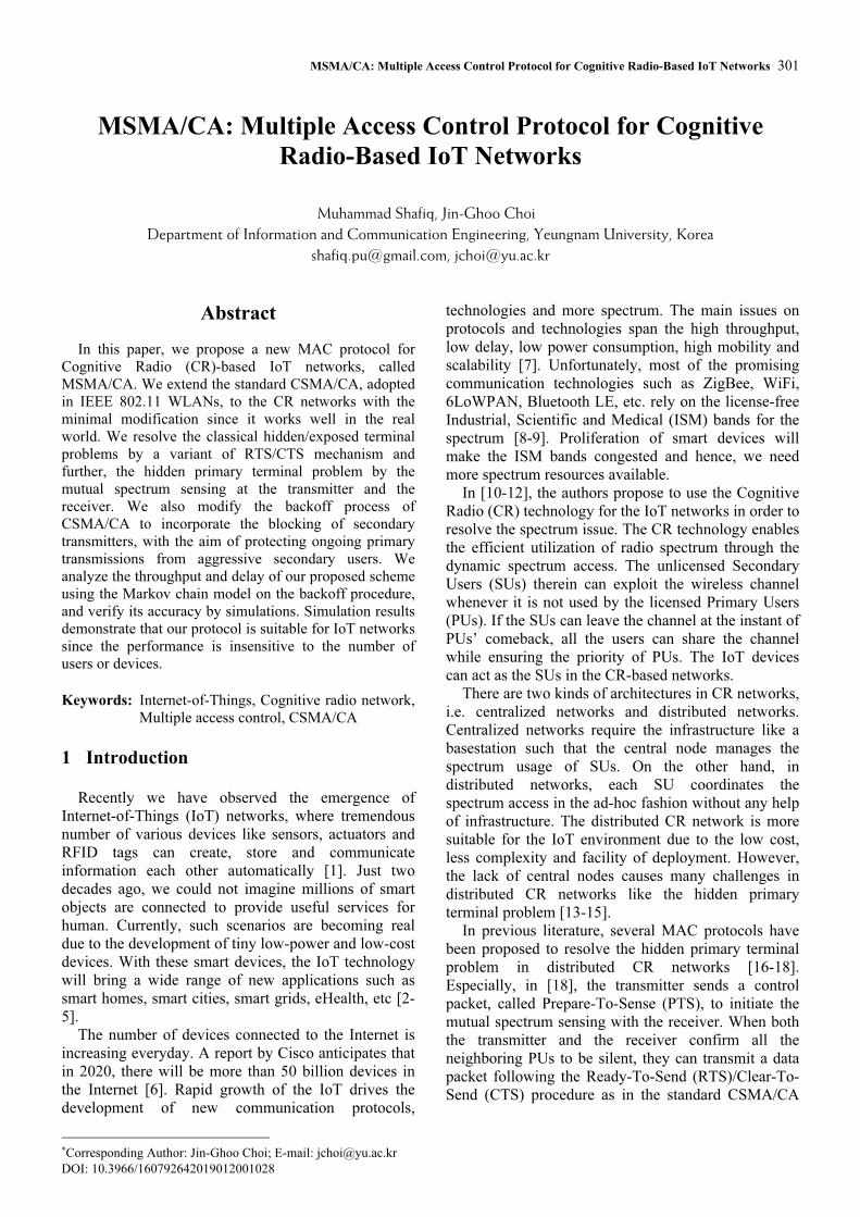
We illustrate the typical packet transmission
procedure under MSMA/CA in Figure 1, which can be
described as follows. First, each SU with packets to
send selects a backoff counter at random. Then the SU
performs the carrier sensing to see whether the channel
is idle or not. If the channel is clear for the DIFS
interval1, the SU decreases its backoff counter one by
one for every idle backoff slot time (whose length is
denoted as σ). In Figure 1, the backoff counter has
been chosen as 4. If there is no transmission by other
SUs until the backoff counter reaches 0, the transmitter
broadcasts an NTS packet to initiate the spectrum
sensing at the receiver. The NTS packet makes the
neighboring SUs silent during the spectrum sensing by
updating their Network Allocation Vectors (NAVs)
[19]. Right after sending the NTS, the transmitter also
conducts the spectrum sensing in conjunction with the
1 This time interval is defined in the IEEE 802.11 standard for
Wireless LANs [19].

MSMA/CA: Multiple Access Control Protocol for Cognitive Radio-Based IoT Networks 303
receiver. If there are no active PUs around, it waits for
the ATS packet from the receiver. When the receiver
decodes the NTS packet successfully, assuming it is
not blocked by the spectrum sensing, the receiver
returns the ATS packet to the transmitter. The
transmitter sends the DATA packet and the receiver
replies by the ACK to confirm the successful packet
delivery. We note that the transmitter does not always
receive the ATS packet for the associated NTS. There
can be multiple NTS packets transmitted at the same
time. Then the collision occurs and the receiver cannot
decode the NTS correctly. Even when the receiver
decodes the NTS packet at success, it can be blocked
by the spectrum sensing and does not return the ATS to
the transmitter. The detailed operation is studied in the
next section for the performance analysis.
Figure 1. Typical packet transmission procedure
We now discuss the backoff procedure in detail. The
primary objective of the backoff mechanism is to avoid
the packet collisions in the secondary network.
However, in the proposed scheme, the backoff process
covers the blocking of the secondary transmitter as
well when the transmitter detects the activity of
adjacent PUs. For each data packet, the transmitter
begins the backoff procedure from stage 0 with the
contention window size 0
W . Hence, the initial backoff
counter is chosen among the integers from 0 to 0
1W − .
Once the counter decreases to 0 in the backoff stage
( 0),m ≥ the SU attempts the packet transmission. If the
transmission is successful, the backoff stage returns to
0 and the SU selects a new backoff counter in the
interval 0
[0, )W at random. Otherwise, the backoff
stage moves up to 1m + , and the backoff counter
should be chosen among 1
[0, )m
W+
. In our protocol, the
selection probability of each backoff number depends
on the cause of the transmission failure. When the
transmission fails due to the transmitter’s blocking, we
choose the backoff counter among 1
[ , )m m
W W+
rather
than 1
[0, )m
W+
. This operation makes the SU be
blocked for m
W slot times at least, and preserves the
range of backoff counters. If not the case, we choose
the backoff counter among 1
[0, )m
W+
with the equal
probability 1
1
mW
+
.
There is a tradeoff between the channel utilization
and the collision probability, according to the
contention window size. Hence, as in the standard
CSMA/CA, we adapt the contention window size
depending on the number of competing SUs.
Specifically, we double the window size whenever a
packet transmission experiences consecutive failures
and the backoff stage moves up. Thus the contention
window size of stage m (≥ 0) is given as where M
denotes the maximum backoff stage. The transmitter
can retransmit the failed packet for retry limit times at
the maximum. The backoff process, however, remains
in the stage M after the M -th trial on.
0
min(2 ,2 ) .m M
mW W= ⋅ (1)
The core of our protocol is the NTS/SS/ATS
mechanism for the packet transmission, where SS
denotes the spectrum sensing. It is designed to combine
the benefits of the RTS/CTS mechanism and the
spectrum sensing. In the standard CSMA/CA, the
transmitter and receiver exchanges RTS/CTS packets
to resolve the hidden/exposed terminal problems by
updating the NAVs of neighboring users. Our
NTS/ATS plays exactly the same function in the
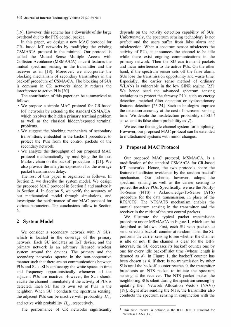
secondary network. Figure 2 illustrates the packet
transmission from SU i to SU j, where the solid lines
represent the Carrier Sense Range (CSR) and the
dotted lines do the Spectrum Sense Range (SSR),
respectively. The NTS packet from SU i keeps the
exposed terminal E silent, in order for the transmitter
to receive the ATS packet successfully. The ATS
packet from SU j lets the hidden terminal H defer the
transmission until the receiver sends the ACK back.
Furthermore, the spectrum sensing in SU j detects the
primary terminal PU, hidden from SU i, and stops the
transmitter sending a data packet by holding the ATS
packet. In this way, our protocol resolves the hidden
primary terminal problem as well as the
hidden/exposed terminal problems.
Figure 2. Packet transmission from SU i to SU j
4 Performance Analysis
In this section, we analyze the performance of our
MAC protocol in terms of throughput and delay. We
first summarize the notations used in the analysis in
Table 1 for further references.
304 Journal of Internet Technology Volume 20 (2019) No.1
Table 1. Summary of notations
Notation Description
1, 0,( )
i iH H Active (inactive) probability of the PUs around SU i
iα Misdetection probability of SU i
iβ False alarm probability of SU i
iC Clear channel probability of SU i at arbitrary time
ip Probability of 1
E when SU i attempts the transmission
1,iq Probability of 2
E when SU i attempts the transmission
2,iq Probability of 3
E when SU i attempts the transmission
is Probability of 4
E when SU i attempts the transmission
kT Length of an k
E slot (k = 1; 2; 3; 4)
iQ Probability of SU i’s queue being backlogged
kτ Transmission attempt probability of SU i
ijn Packet transmission probability of SU i to SU j
mW Contention window size of the m -th backoff stage
M Maximum backoff stage
iq Sum of probabilities 1,i
q and 2,iq
ie Failure probability of transmission attempts of SU i
,m bπ Probability of the backoff counter being b in stage m
bP Occurrence probability of backoff slots
sP Occurrence probability of successful transmission slots
fP Occurrence probability of failed transmission slots
θ Throughput of MSMA/CA
S Length of an arbitrary slot
σ Length of a backoff slot
sT Length of a successful transmission slot
fT Length of a failed transmission slot
HDR Header size of a packet
L Payload size of a packet
R Channel transmission rate
iD Delay of a HOL packet of SU i
iK Number of slots a HOL packet of SU i sees
,m id Average number of slots for SU i to stay at stage m
4.1 Packet Transmission Process
We observe the packet transmission process of our
MSMA/CA. Each SU initiates the packet transmission
when its backoff counter decreases to 0 and the packet
queue is not empty. The transmission attempt
encounters one of the four mutually exclusive events:
(1) Blocking at the transmitter, (2) Collision of
multiple NTS packets, (3) Blocking at the receiver and
(4) Successful transmission. We denote each event as
1E ,
2E ,
3E and
4E , respectively. We henceforth
calculate the probability of the individual event and
specify how much time the transmitter spends when
each event happens. To this end, we define the clear
channel probability i
C of an SU i as
1, 0,
(1 ) .i i i i i
C H Hα β= + − . (2)
where we recall that i
α is the misdetection probability
of SU i, i
β is its false alarm probability, 0,i
H is the
inactive probability of the PUs around SU i and 1,i
H is
the active probability of the PUs, respectively. Thus,
when SU i performs the spectrum sensing, it decides
the adjacent PUs to be inactive with probability i
C and
active with probability 1i
C− .
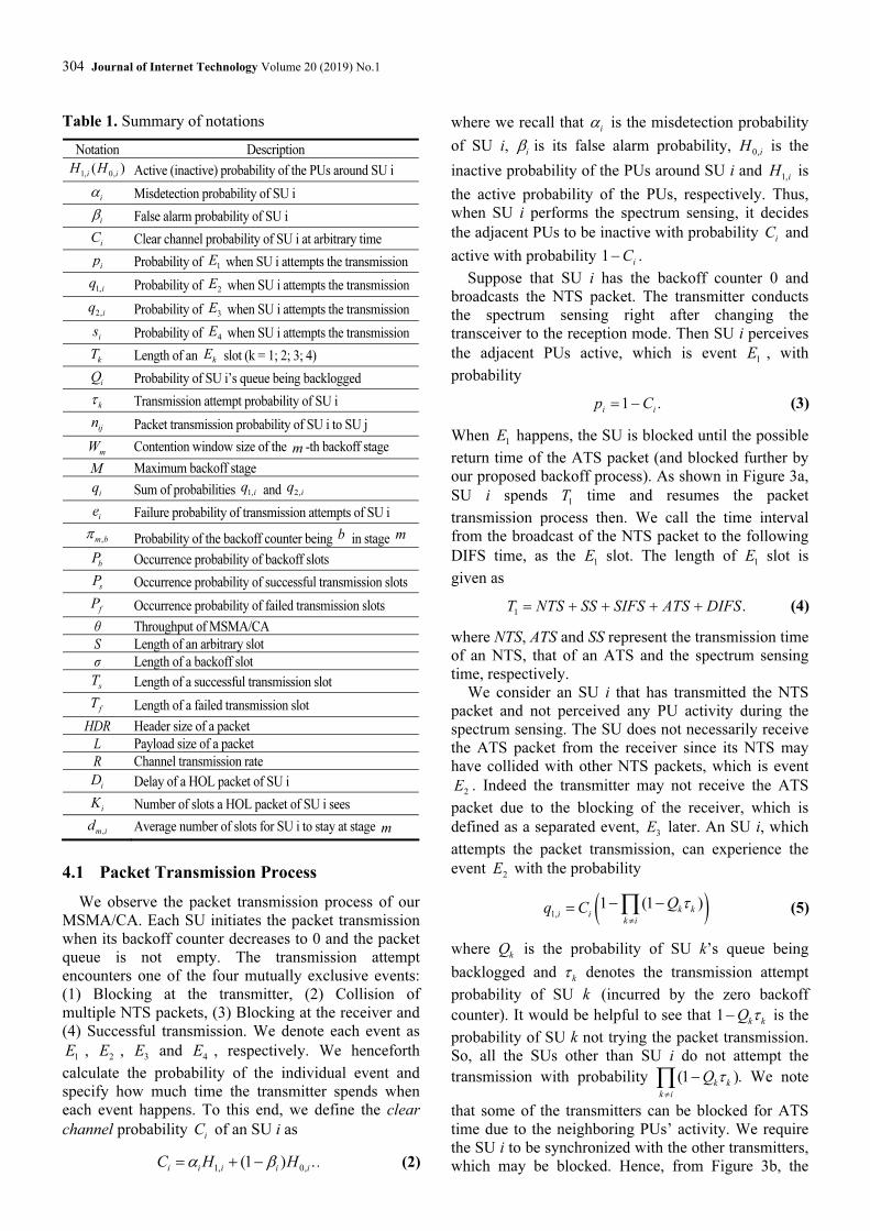
Suppose that SU i has the backoff counter 0 and
broadcasts the NTS packet. The transmitter conducts
the spectrum sensing right after changing the
transceiver to the reception mode. Then SU i perceives
the adjacent PUs active, which is event 1
E , with
probability
1 .i ip C= − (3)
When 1
E happens, the SU is blocked until the possible
return time of the ATS packet (and blocked further by
our proposed backoff process). As shown in Figure 3a,
SU i spends 1T time and resumes the packet
transmission process then. We call the time interval
from the broadcast of the NTS packet to the following
DIFS time, as the 1
E slot. The length of 1
E slot is
given as
1
.T NTS SS SIFS ATS DIFS= + + + + (4)
where NTS, ATS and SS represent the transmission time
of an NTS, that of an ATS and the spectrum sensing
time, respectively.
We consider an SU i that has transmitted the NTS
packet and not perceived any PU activity during the
spectrum sensing. The SU does not necessarily receive
the ATS packet from the receiver since its NTS may
have collided with other NTS packets, which is event
2E . Indeed the transmitter may not receive the ATS
packet due to the blocking of the receiver, which is
defined as a separated event, 3
E later. An SU i, which
attempts the packet transmission, can experience the
event 2
E with the probability
( )1,1 (1 )
k ki i
k i
Qq C τ
≠
− −
= ∏ (5)
where k
Q is the probability of SU k’s queue being
backlogged and k
τ denotes the transmission attempt
probability of SU k (incurred by the zero backoff
counter). It would be helpful to see that 1k k
Q τ− is the
probability of SU k not trying the packet transmission.
So, all the SUs other than SU i do not attempt the
transmission with probability (1 ).k k
k i
Q τ
≠
−∏ We note
that some of the transmitters can be blocked for ATS
time due to the neighboring PUs’ activity. We require
the SU i to be synchronized with the other transmitters,
which may be blocked. Hence, from Figure 3b, the
MSMA/CA: Multiple Access Control Protocol for Cognitive Radio-Based IoT Networks 305
length of 2
E slot is given as
2
.T NTS SS SIFS ATS DIFS= + + + + (6)
Suppose that SU i has sent the NTS packet and is
waiting for the response from the corresponding SU j.
Even though the SU j has received the NTS packet
successfully, it cannot return the ATS if the SU is
blocked by the spectrum sensing. That is the event 3
E .
When SU i sends the data packets to SU j with
probability ij
η , we can calculate the probability of 3
E
as
( )2,,
(1 )(1 ) (1 ) .j j j k ki i ij
k i jj i
Q C Qq C τ τη
≠≠
− − −
= ∏∑ (7)
We have let the non-blocked transmitter wait for ATS
time in the event 2
E . Similarly, when the receiver is
blocked, it also waits for ATS time to keep pace with
the transmitter. As shown in Figure 3c, the length of
3E slot is given as
3
.T NTS SS SIFS ATS DIFS= + + + + (8)
Finally, we consider the successful packet
transmission case. SU i sends the NTS packet and after
finding the PUs inactive, it waits for the ATS from the
receiver SU j. If the SU j is not blocked, it returns the
ATS packet. Then SU i transmits a DATA packet and
SU j responds by the ACK always since we assume the
error-free channel. For SU i, the occurrence probability
of 4
E is given as
( ),
(1 ) (1 ) .j j j k ki i ij
k i jj i
Q C Qs C τ τη
≠≠
− −
= ∏∑ (9)
Figure 3d shows that the length of 4
E slot, i.e. the time
interval for the successful packet transmission, can be
written as
4T NTS SS SIFS ANTS SIFS DATA
SIFS ACK DIFS
= + + + + +
+ + +
(10)
where DATA and ACK denote the transmission time
of a DATA and that of an ACK, respectively.
4.2 Throughput
We analyze the performance of our proposed MAC
protocol under the following assumptions.
‧ The secondary network is a single hop such that an
SU can transmit packets to other SUs directly.
‧ Each SU has the packets to send at all times, i.e.
1i
Q = for every SU i.
‧ An SU retransmits a failed data packet until it is
delivered successfully. In other words, we set the
retry limit to infinite.
‧ When an SU attempts a transmission, it succeeds
with a constant probability regardless of the current
backoff stage or the number of SUs.
(a) Blocking at the transmitter
(b) Collision of multiple NTS packets
(c) Blocking at the receiver
(d) Successful transmission
Figure 3. Events following the packet transmission
attempt
We observe the backoff process of an arbitrary SU i
at the beginning of each slot. Every slot, the backoff
counter decreases one by one and when it reaches 0,
SU i starts the packet transmission process. If the
transmission is successful, SU i returns to the initial
backoff stage and otherwise, its backoff stage moves
up one step. If the SU i has encountered 1
E at stage
[0, ),m M∈ the new backoff counter is chosen among
1[ , )
m mW W
+ with the equal probability. On the other
hand, if the SU has suffered either 2
E or 3
E , its
backoff counter is chosen among 1
[0, )m
W+
.
We model the backoff process as a discrete time
Markov chain with two dimensional states ( , )m b ,
where [0, ]m M∈ is the backoff stage and [0, )M
b W∈
is the backoff counter in the stage m . We illustrate the
Markov chain in Figure 4, where ,1 2,i i i
q q q= + and the
subscript i can be dropped without confusion. We also
use the notation i i ie p q= + henceforth to denote the

306 Journal of Internet Technology Volume 20 (2019) No.1
transmission error (or failure) probability of SU i. The
state transition probabilities of our Markov chain can
be written as eq. (11). As the Markov chain is
constructed, we can set up the detailed balance
equation for each state ( , )m b , and calculate the steady
state probability ,m b
π by solving the system of
equations. Then, the transmission attempt probability
of an SU i can be written as
1
0
2(1 )(1 ) (2 )(2 ) 1
4(1 2 ) 2i
M
i i i i i
i
e
p e e p eWτ
−
⎛ ⎞+ − − ++= ⎜ ⎟⎜ ⎟−⎝ ⎠
(12)
See the Appendix for the derivation of i
τ .
Figure 4. Markov chain model of the backoff process
0
0
1
1
Pr{( , ) ( , 1)} 1 for [0, ], [1, )
1 ( )Pr{( , 0) (0, )} for [0, ], [0, )
Pr{( , 0) ( 1, )} for [0, ], [0, )1
Pr{( , 0) ( 1, )} for [0, ], [ , )
Pr{( , 0) ( , )} for [0,
m
m
m
m m
m m
M
m b m b m M b W
p qm b m M b W
W
qm m b m M b W
W
p qm m b m M b W W
W W
qM M b b
W
+
+
→ − = ∈ ∈
− +→ = ∈ ∈
→ + = ∈ ∈+
→ + = + ∈ ∈
→ = ∈1
1
1
)
Pr{( , 0) ( , )} for [ , ).
M
M m
M M
W
p qM M b b W W
W W
−
−
−
⎧⎪⎪⎪⎪⎪⎪⎪⎨⎪⎪⎪⎪⎪⎪
→ = + ∈⎪⎩
(11)
We can classify the slots into the backoff slot and
the event slots (i.e., 1
E , 2
E , 3
E or 4
E ). The backoff
slots occurs when no SU attempts to transmit packets,
whose occurrence probability is written as
(1 ).b i
i
P τ= −∏ (13)
We know that SU i transmits a data packet
successfully when its backoff counter becomes 0 and
the event 4
E happens, whose probability is given as
i isτ . So, we have the slots with the successful data
transmission with probability
.
s i i
i
P sτ=∑ (14)
The other slots correspond to the failed packet
transmissions. Such slots are found with probability
MSMA/CA: Multiple Access Control Protocol for Cognitive Radio-Based IoT Networks 307
1 ( ).f b sP P P= − +
The throughput of our proposed scheme can be
written as
Average payload bits transmitted in a slot.
Average slot lengthθ = (15)
We obtain the average of the slot length as
[ ] [ ] [ ].b s s f fE S P P E T P E Tσ= + + (16)
where 4s
T T= and 1 2 3( ).fT T T T= = = From eq. (10),
we can see that
[ ] [ ]
3
( [ ]) /
3
sE T NTS SS ATS E DATA
ACK SIFS DIFS
NTS SS ATS HDR E L R
ACK SIFS DIFS
= + + +
+ + +
= + + + +
+ + +
(17)
where HDR , L and R denote the header size,
payload size and transmission rate, respectively. From
eq. (4), we know that 1T is fixed and thus
1[ ]fE T T= .
Conclusively, the throughput of our protocol is given
as
1
[ ].
[ ]
s
b s s f
P E L
P P E T P Tθ
σ=
+ +
(18)
4.3 Delay
We now analyze the average delay of a data packet
on the condition that the packet transmission is
successful. In SU i, each Head-Of-Line (HOL) packet
at the queue sees i
K slots until the successful
transmission, through the backoff process. Then the
packet delay i
D can be written as
1
.
iK
i k s
k
D S T
=
= +∑ (19)
where k
S denotes the length of the k-th slot the packet
observes. So, the average packet delay is given as
1
[ ] [ ]
[ ] [ ] [ ]
iK
i sk
k
i s
E D E E TS
E K E S E T
=
⎡ ⎤= +⎢ ⎥
⎣ ⎦
= ⋅ +
∑ (20)
where we remove the subscript of k
S without loss of
generality. We have obtained the average slot length
[ ]E S already in eq. (16) and the average successful
transmission time [ ]s
E T in eq. (17). We hence need to
calculate the average number of backoff slots, [ ]i
E K ,
to the successful transmission.
Each packet transmission of SU i begins from the
backoff stage 0. It stays in stage 0 for 0
1
0
0,
0 0
11
2
W
i
b
Wd b
W
−
=
−
= =∑ slot times in average until the
transmission attempt. If the SU i transmits a packet at
stage 1 (0, ]m M− ∈ and does not succeed, the backoff
stage moves up to m and the backoff counter is chosen
among 0 to 1m
W − . We recall that each number can be
chosen as the backoff counter with different
probabilities, depending on the cause of the
transmission failure. Once SU i enters the backoff
stage (0, ]m M∈ , it stays there in average for
1
1
1 1
,
0 1
1 13 2 1
4 2
4.
8 2
m m
m
W W
i ii
m i
b b W m mm
m m
i
i i i
m
p qqd b b
W WW
W Wq
e p eW
−
−
− −
= = −
− −
⎛ ⎞+= + ⎜ ⎟
⎝ ⎠
− −= +
−= −
∑ ∑
(21)
For the third equality, we recall 1
2m m
W W−
= and
.
i i ie p q= + Furthermore, we let
, ,m i M id d= for
1m M≥ + since the backoff process is in stage M
during the M-th or more retrials.
If a data packet is transmitted successfully at backoff
stage m, whose probability is (1 )m
i ie e− , it has passed
through ,
0
m
n i
n
d
=
∑ slots in average. So, [ ]i
E K can be
written as
, , ,
0 0 0 0
(1 ) (1 ) .m m n
i i n i i n i i i n i
m n n m n n
e e d e d e e d
∞ ∞ ∞ ∞ ∞
= = = = =
⎛ ⎞− = − =⎜ ⎟
⎝ ⎠∑ ∑ ∑ ∑ ∑ (22)
Hence, the number of slots to the successful
transmission is given as
, ,
0 1
,0
0 1
1
0
[ ]
42
8 2
1 (2 ) (2 )4.
1 2 18 2(1 )
M
n n
i i n i i n i
n n M
M
n ni i i
i i M i
n n M
M M
i i ii i i
i i i
E K e d e d
e p ee e dW
e e ee p eW
e e e
∞
= = +
∞
= = +
+
= +
−⎛ ⎞= +−⎜ ⎟
⎝ ⎠
⎛ ⎞−−+= −⎜ ⎟
− − −⎝ ⎠
∑ ∑
∑ ∑ (23)
For the second equality, we replaced ,n i
d with
4
8 2
i i i
n
e p eW
−
− for [0, ]n M∈ from eq. (21) and for
1n M≥ + , ,n i
d is fixed as ,M i
d . The third equality
follows after some algebra and rearrangement of terms.
5 Simulation Results
We have developed the simulation code with the
C++ language, considering all the details of our
MSMA/CA protocol. We assume that each SU i has
the ideal spectrum sensing capability, i.e. 0i
α = and
0i
β = . Further, the channel is assumed error-free such
that the transmission error does not occur. We
308 Journal of Internet Technology Volume 20 (2019) No.1
summarize the default parameter values used in the
simulations in Table 2. Note that the activity rate of
PUs, 1,i
H is set equal for every SU i such that each SU
experiences the identical performance in the proposed
scheme. So, in this section, we drop the subscript i
denoting SU i.
Table 2. Default parameters in simulations
Parameter name Value
PHY header 120 bits
MAC header 272 bits
Payload 8184 bits
NTS 160 bits + PHY header
ATS (and ACK) 112 bits + PHY header
SIFS time 10 µs
DIFS time 50 µs
Backoff slot time (σ) 20 µs
PU activity rate (H1,i) 0.01
Spectrum sensing time 0.5 ms
Channel transmission rate (R) 1 Mbps
Initial CW size (W0) 32
Maximum CW size (WM) 1024
Maximum backoff stage (M) 5
We have run each simulation 1000 times and
averaged them to obtain one simulation result. We
compare the
analysis results (shown in lines) with the simulation
results (shown in markers) in Figure 5 and Figure 6.
We can observe that our analysis is very accurate since
the two results match each other closely.
Figure 5(a) shows the throughput, normalized by the
channel transmission rate R, of our proposed scheme
while varying the number of SUs, N. We consider the
minimum contention window size of 32, 64 and 128,
respectively. As the number of SUs increases, the
normalized throughput increases first and then
decreases monotonically. When the number of SUs is
small, the channel time is wasted by backoff slots since
the smallest backoff counter chosen by SUs becomes
large. Then the system has low throughput. On the
other hand, if the number of SUs is large, there happen
frequent collisions and the throughput decreases.
Further, we observe that the large initial contention
window size is better for many SUs since it reduces the
collision rate significantly.
In Figure 5(b), we demonstrate the effect of PU
activity rate 1,i
H on the normalized throughput. We
consider the number of SUs of 10, 30 and 50,
respectively. Regardless of the number of SUs, the
throughput decreases monotonically as 1,i
H increases
since the available channel time decreases. When the
PU activity rate is low, the throughput is slightly better
for small N since the collisions do not happen often.
Conversely, when the PU activity rate is high, the
throughput is larger with large N. It can be explained as
follows. If the PUs are active with high probability,
many SUs are liable to be blocked after the spectrum
sensing and cannot participate in the packet
transmission. Hence the overall throughput decreases.
We provide the normalized throughput for various
numbers of SUs in Figure 5(c), where we consider the
maximum backoff stage M of 3, 5 and 7, respectively.
The throughput is not sensitive to the M when the
number of SUs is small since the collisions do not
happen often. However, when the number of SUs is
large, the throughput decreases fast with the small M
since the range of backoff counters does not increase
enough while collisions occur frequently.
In Figure 6, we show the transmission attempt
probability τ while increasing the number of SUs. We
can see that τ decreases with the number of SUs since
the frequent collisions make the backoff counters
increase. We also observe that when the initial
contention window size is large, the transmission
attempt probability decreases even though the
collisions occur infrequently since the initial backoff
counters are large.
We investigate the average delay D of the
successfully delivered packets in Figure 7. The delay
increases as the number of SUs increases for given
initial contention windows size 0
W (in Figure 7(a)) and
maximum backoff stage M (in Figure 7(b)). When
there are many SUs, each SU experiences frequent
collisions and its backoff counter becomes large due to
the consecutive transmission failures, which leads to
the large transmission delay. We observe that when 0
W
(or M) is small, the average delay decreases even with
more collisions since the backoff counters chosen are
small.
6 Conclusion
We have proposed a new MAC protocol, called
MSMA/CA, for CR-based IoT networks. Our scheme
combines the RTS/CTS mechanism of the standard
CSMA/CA with the mutual spectrum sensing
technique of CR networks. As a result, our MAC
protocol resolves the classical hidden/exposed terminal
problems as well as the hidden primary terminal
problem at the same time. We also modify the backoff
process of CSMA/CA in order to incorporate the
blocking mechanism of SUs. The SUs hold the packet
transmission when they detect the active PUs during
the spectrum sensing, by choosing a large backoff
counter. Hence the PUs are protected from the
persistent transmission attempts of SUs. We have
analyzed the proposed protocol and obtained the
throughput and delay performances. Simulation results
show that our analysis is accurate for various scenarios.
Our scheme is a good candidate for the MAC protocol
of CR-based IoT networks since the performance is
insensitive to the number of users (or IoT devices)
while providing sufficient priority to the incumbent PUs.

MSMA/CA: Multiple Access Control Protocol for Cognitive Radio-Based IoT Networks 309
(a) Normalized throughput vs. number of SUs
(for various 0
W s)
(b) Normalized throughput vs. PU activity rate
(c) Normalized throughput vs. number of SUs
(for various Ms)
Figure 5. Normalized throughput
Figure 6. Transmission attempt probability vs. number
of SUs
(a) Effect of the initial contention window size 0
W
(b) Effect of the maximum backoff stage M
Figure 7. Average delay vs. number of SUs
310 Journal of Internet Technology Volume 20 (2019) No.1
Acknowledgments
This research was supported by the MSIT (Ministry
of Science and ICT), Korea, under the ITRC
(Information Technology Research Center) support
program (IITP-2017-2016-0-00313) supervised by the
IITP (Institute for Information & communications
Technology Promotion). J.-G. Choi is the corresponding
author.
References
[1] B. Rajkumar, A.V. Dastjerdi, Internet of Things: Principles
and Paradigms, Elsevier, 2016.
[2] M. R. Palattella, M. Dohler, A. Grieco, G. Rizzo, J. Torsner,
T. Engel, L. Ladid, Internet of Things in the 5G Era: Enablers,
Architecture and Business Models, IEEE Journal on Selected
Areas in Communications, Vol. 34, No. 3, pp. 510-527, 2016.
[3] A. Zanella, N. Bui, A. Castellani, L. Vangelista, M. Zorzi,
Internet of Things for Smart Cities, IEEE Internet of Things
Journal, Vol. 1, No. 1, pp. 22-32, 2014.
[4] C. Perera, C. H. Liu, S. Jayawardena, The Emerging Internet
of Things Marketplace from an Industrial Perspective: A
Survey, IEEE Transactions on Emerging Topics in
Computing, Vol. 3, No. 4, pp. 585-598, 2015.
[5] D. V. Dimitrov, Medical Internet of Things and Big Data in
Healthcare, Healthcare Informatics Research, Vol. 22, No. 3,
pp. 156-163, 2016.
[6] D. Evans, The Internet of Things: How the Next Evolution of
the Internet is Changing Everything, Cisco Internet Business
Solutions Group, April, 2011.
[7] S. Li, L.D. Xu, S. Zhao, The Internet of Things: A Survey,
Information Systems Frontiers, Vol. 17, No. 2, pp. 243-259,
2015.
[8] A. Fuqaha, A. Guizani, M. Mohammadi, M. Aledhari, M.
Ayyash, Internet of Things: A Survey on Enabling
Technologies, Protocols, and Applications, Communications
Surveys and Tutorials, Vol. 17, No. 4, pp. 2347-2376, 2015.
[9] M. Elkhodr, S. Shahrestani, H. Cheung, Emerging Wireless
Technologies in the Internet of Things: a Comparative Study,
International Journal of Wireless and Mobile Networks
(IJWMN), Vol. 8, No. 5, pp. 67-82, 2016.
[10] R. Priyanka, K. D. Singh, J. M. Bonnin, Cognitive Radio for
M2M and Internet of Things: A Survey, Computer
Communications, Vol. 94, pp. 1-29, 2016.
[11] K. A. Ali, M. H. Rehmani, A. Rachedi, When Cognitive
Radio meets the Internet of Things, Proceedings of EEE
Wireless Communications and Mobile Computing Conference
(IWCMC), Cyprus, 2016, pp. 469-474.
[12] S. M. Ali, S. Zhang, C. Maple, Cognitive Radio Networks for
Internet of Things: Applications, Challenges and Future,
Proceedings of the International Conference on Automation
and Computing, London, UK, 2013, pp.13-14.
[13] G. Ganesan, Y. Li, Cooperative Spectrum Sensing in
Cognitive Radio Networks, Proceedings of IEEE Int.
Symposium on New Frontiers in Dynamic Spectrum Access
Networks, Baltimore, MD, 2005, pp. 137-143.
[14] D. Cabric, A. Tkachenko, R. Brodersen, Spectrum Sensing
Measurements of Pilot, Energy, and Collaborative Detection,
Proceeding of IEEE Military Communications Conference,
Washington, DC, 2006, pp. 1-7.
[15] G. Ganesan, Y. Li, Agility Improvement through Cooperative
Diversity in Cognitive Radio, Proceedings of IEEE Global
Communications Conference, Vol. 5, St. Louis, MO, 2005, pp.
2505-2509.
[16] Q. Zhao, L. Tong, A. Swami, Y. Chen, Decentralized
Cognitive MAC for Opportunistic Spectrum Access in Ad
Hoc Networks: A POMDP Framework, IEEE Journal on
Selected Areas in Communications, Vol. 25, No. 3, pp. 589-
600, 2007.
[17] S. C. Jha, U. Phuyal, M. M. Rashid, V. K. Bhargava, Design
of OMCMAC: An Opportunistic Multi-channel MAC with
QoS Provisioning for Distributed Cognitive Radio Networks,
IEEE Transactions on Wireless Communications, Vol. 10, No.
10, pp. 3414-3425, 2011.
[18] Q. Chen, W. Wong, M. Motani, Y. Liang, MAC Protocol
Design and Performance Analysis for Random Access
Cognitive Radio Networks, IEEE Journal on Selected Areas
in Communications, Vol. 31, No. 11, pp. 2289-2298, 2013.
[19] Wireless LAN Medium Access Control (MAC) and Physical
Layer (PHY) Specifications, IEEE Std 802.11-2007 Part 11,
2007.
[20] A. M. Wyglinski, M. Nekovee, T. Hou, Cognitive Radio
Communications and Networks: Principles and Practice,
Academic Press, 2009.
[21] G. Bianchi, Performance Analysis of the IEEE 802.11
Distributed Coordination Function, IEEE Journal on Selected
Areas in Communications, Vol. 18, No. 3, pp. 535-547, 2000.
[22] L. Wei, O. Tirkkonen, Spectrum Sensing in the Presence of
Multiple Primary Users, IEEE Transactions on
Communications, Vol. 60, No. 5, pp. 1268-1277, 2012.
[23] D. T. C. Wong, S. Zheng, Y. Liang, Cognitive Multi-Channel
MAC Protocols with Perfect and Imperfect Sensing,
Proceeding of IEEE International Conference on
Communications, Kyoto, Japan, 2011.
[24] Y. Tevfik, H. Arslan, A Survey of Spectrum Sensing
Algorithms for Cognitive Radio Applications,
Communications Surveys and Tutorials, Vol. 11, No.1, pp.
116-130, 2009.
Biographies
Muhammad Shafiq is a Ph.D.
candidate in Department of
Information and Communication
Engineering, Yeungnam University,
Korea. He received a M.S. degree in
Computer Science from UIIT., PMAS.,
Arid Agriculture University,
Rawalpindi, Pakistan. He also received a master’s
degree in Information Technology (IT) from
University of the Punjab, Gujranwala, Pakistan. He has
MSMA/CA: Multiple Access Control Protocol for Cognitive Radio-Based IoT Networks 311
been working with the Faculty of Computing and IT
University of Gujrat, Gujrat, Pakistan as a faculty
member since 2010. He was with the Department of
Computer Science and IT, Federal Urdu University,
Islamabad, Pakistan in 2009. His research interests
include the design of spectrum management, routing,
and medium access control protocols for Mobile Ad
Hoc Networks, Internet of Things, and Cognitive
Radio Networks.
Jin-Ghoo Choi received his Ph.D.
degree from the School of Electrical
Engineering and Computer Science,
Seoul National University in 2005.
From 2006 to 2007, he worked for
Samsung Electronics as a senior
engineer. In 2009, he was with the
Department of Electrical and Computer Engineering in
The Ohio State University as a visiting scholar. He
joined the Department of Information and
Communication Engineering in Yeungnam University
as a faculty member in 2010. His research interests
include performance analysis of communication
networks, resource management in wireless networks,
and wireless sensor network.
312 Journal of Internet Technology Volume 20 (2019) No.1
Appendix
Derivation of i
τ : We derive the transmission
attempt probability i
τ of SU i by analyzing the
Markov chain of Figure 4. For simplicity, we here drop
the subscript i that denotes SU i.
We first list up the detailed balance equation at each
state ( , )m b as follows. Defining ,0
0
M
m
m
τ π
=
=∑ , we can
write the balance equations of the backoff stage 0 as
0, 0, 1 0
0
0 0
0
1 ( 1)for [0, 1),
1 ( ), 1 .
b b
pb W
W
p qW
W
π π τ
π τ
+
− += + ∈ −
− +− =
(24)
The balance equations of stage [1, 1)m M∈ − are given
as
, , 1 1,0 1
, , 1 1,0 1 1
1,0
for [0, ),
2for [ , ),
21 .
m b m b m m
m
m b m b m m m
m
m m m
m
qb W
W
p qb W W
W
p qW
W
π π π
π π π
π π
+ − −
+ − − −
−
= + ∈
+= + ∈
+− =
(25)
Lastly, the balance equations for stage M are as follows.
, , 1 1,0 ,0 1
, , 1 1,0 ,0 1 1
1,0 ,0
( ) for [0, ),
2( ) for [ , ),
21 ( ) .
M b M b M M M
M
M b M b M M M M
M
M M M M
M
qb W
W
p qb W W
W
p qW
W
π π π π
π π π π
π π π
+ − −
+ − − −
−
= + + ∈
+= + + ∈
+− = +
(26)
We sum up the equations in (24) to obtain
0 0
1 1
0, 0,
0 1
(1 ( )) .W W
b b
b b
p qπ π τ
− −
= =
= + − +∑ ∑ (27)
which leads to
0,0
(1 ( )) .p qπ τ+ − + (28)
In the same way, by summing up the eqs. in (25), we
have
,0 1,0 0,0
( ) ( ) .m
m mp q p qπ π π
−
= + = + (29)
for 1, , 1m M= −� and, from the eqs. in (26), we
obtain ,0 1,0 ,0
( )( )M M M
p qπ π π−
= + + , i.e.
,0 1,0 0,0
( ).
1 ( ) 1 ( )
M
M M
p q p q
p q p qπ π π
−
+ += =
− + − +
(30)
We next observe the eqs. of (24) and by the back
substitution, obtain the steady state probabilities for the
stage 0 as
0, 0
0
0
0,0 0
0
1 ( )( )
for [0, ).
b
p qW b
W
W bb W
W
π τ
π
− += −
−
= ∈
(31)
For the stage [1, )m M∈ , we have the steady state
probabilities from eq. (25) as
1,0
,
1,0
( ) for [0, 1)
2( ) for [ 1, ).
mm m
m
m b
m m m m
m
qp W b b W
W
p qW b b W W
W
π
π
π
−
−
⎧ ⎛ ⎞+ − ∈ −⎪ ⎜ ⎟
⎪ ⎝ ⎠⎨
+⎪ − ∈ −⎪⎩
(32)
Further, from eq. (26), we have ,M b
π as
1,0 ,0 1
1,0 ,0 1
( )( ) for [0, )
2( ) ( ) for [ , ).
mM M m
m
M M m M m
m
qp W b b W
W
p qW b b W W
W
π π
π π
− −
− −
⎧ ⎛ ⎞+ −+ ∈⎪ ⎜ ⎟
⎪ ⎝ ⎠⎨
+⎪ + − ∈⎪⎩
(33)
We now calculate the probability of the backoff
process being in each individual stage. From eq. (31),
the probability of stage 0 is given as
0
1
0
0 0, 0,0
0
1.
2
W
b
b
Wπ π π
−
=
+
= =∑ (34)
For stage [1, 1)m M∈ − , from eq. (32), we have
1
1,0
,
0
3 2.( )
2 2
mW
m
m m b m
b
p qW p q
π
π π
−
−
=
+⎛ ⎞= = + +⎜ ⎟⎝ ⎠
∑ (35)
The result for the last stage M is obtained from eq. (33)
as
11,0 ,0
,
0
3 2.( )
2 2
MW
M M
M M b M
b
p qW p q
π π
π π
−
−
=
+ +⎛ ⎞= = + +⎜ ⎟⎝ ⎠
∑ (36)
We note that 0
1
MW
M
m
π
=
=∑ since the total steady state
probability should be 1. Using e p q= + , we have the
following equation.
1
0
1
11,0
0
1
1,0 ,0
0,0 ,01
0
1
0,0 0,0
0 0
( )2 2
( ) ( )2 22 2
( ) ( )2 22 2
1 (2 ) (1 )( 1) (2 )
2 2 1 2 1
M
m M
m
M
m
m
m
M M
m M
M
Mm
m m
m
M M
pe W e
p pe W e e W e
p pe e W e e W e
e e eW e p W
e e
π π π
π
π
π π
π π
π
π π
−
=
−
−
=
−
−
=
+ +
⎛ ⎞= + + +⎜ ⎟⎝ ⎠
⎛ ⎞ ⎛ ⎞+ ++ + + +⎜ ⎟ ⎜ ⎟⎝ ⎠ ⎝ ⎠
⎛ ⎞ ⎛ ⎞= + ++ + + +⎜ ⎟ ⎜ ⎟⎝ ⎠ ⎝ ⎠
⎛ − −= + + + +
− −
∑
∑
∑
1.
⎞⎜ ⎟⎝ ⎠
=
(37)

MSMA/CA: Multiple Access Control Protocol for Cognitive Radio-Based IoT Networks 313
Recalling 0,0
1 e
π
τ =
−
from eq. (28), we have the
transmission attempt probability τ of eq. (12) after
rearranging the terms in eq. (37).

314 Journal of Internet Technology Volume 20 (2019) No.1