msk-1541s industrial sewing machine - … · industrial sewing machine ... 2.insert the bobbin...
TRANSCRIPT

MSK-1541S Industrial Sewing Machine
INSTRUCTION MANUAL

1. Brief introduction.................................................................................12. Main specifications..............................................................................13. Installation...........................................................................................14. Installing the oil box............................................................................25. Adjusting the tension of the belt.........................................................26. Installing the belt cover.......................................................................27. Lubrication.........................................................................................38. Installing the needle...........................................................................39. Threading the bobbin thread..............................................................410. Installing the rotating hook body.......................................................411. Installing the winding guider.............................................................412. Winding the bobbin thread...............................................................413. Threading ........................................................................................514. Adjusting the stitch length.................................................................515. Adjusting the thread tension.............................................................516. Adjusting the thread take-up spring..................................................617. Presser foot lifter..............................................................................618. Adjusting the pressure of the presser foot........................................619. Relationship between needle and rotating hook..............................620. Adjusting the alternating amount of presser foot..............................721. Sewing speed list..............................................................................722. Troubleshooting................................................................................7
1. Arm and bed....................................................................................8- 92. Upper shaft and thread take-up mechanism................................10-113. Needle bar vibrating parts...........................................................12-134. Upper feed parts..........................................................................14-155. Feed mechanism.........................................................................16-176. Lower shaft and rotating hook shaft............................................18-197. Thread tension and winding parts...............................................20-218. Knee control parts.......................................................................22-239. Lubrication..................................................................................24-2510. Accessories...............................................................................26-27
CONTENT
Operation Instruction
Parts Manua

11
1. Brief introduction
This machine adpots specific mechanism and timing feed, which can ensure smooth feeding, low noise, and beautiful stitches in apperance. It is constructed with slide link thread take-up, horizontal large rotating hook crochet,synchronic driving. This machien is widely used in the factory of suitcase, sofa, tarpaulins, tents, bag, etc.
Heavy duty
2500 spm
9mm
36mm
DP*17 (Nm125-Nm180) standard Nm160 (23#)
Auto-lubrication
Horizontal rotating hook
9mm by hand, 16mm by knee
370W
2. Mian specifications
Application
Max.sewing speed
Max.stitch length
Needle bar stroke
Needle
Lubrication
Rotating hook
Height of presser foot lift
Motor
3. Installation (Fig.1)
1.Installation of the table connecting hook bracket and rubber cushion. Fix the connecting hook bracket 1 and the rubber cushion 2 on the table by screw 3. 2.Installing the oil reservoir. Set the oil reservoir 4 onto the table by six screws as shown in the Fig. 3.Install the knee control connector 5, knee control lift crank 9 and bent bar 7 according to the direction of the knee control lift bar shaft 8. 4.Adjust the direction of part 6,10, 11 by set screw.
Table
In one line

22
33
44
1.Tighten the column 7 into the screw hole on the machine head. 2.Install the belt cover (right) 1 on the machine head by set screw 2 and 8. 3.Connect the belt cover (left) 3 to the claw AB of the belt cover (right) 1. 4.Tighten the belt cover (left) 3 by set screws 4, 5 and 6.
Note: After installing the belt cover, make sure that the belt cover is not touch with the belt and flywheel.
4. Installing the oil box (Fig2)
1.Install the bolt 1, oil seal 2 and spacer 3 onto the oil reservoir, and then put the cushion 5 and spacer 8 into the set screw 4, then set it by nut 6. 2.Tighten the oil pot 7 onto the bolt 1.
5. Adjusting the tension of the belt (Fig.3)
When adjusting the tension of the belt, please move the height of the motor, and press down the middle of the blet with the force of 9.8N. Then there will be a slack of 15mm.
6. Installing the belt cover (Fig.4)
FlywheelFlywheel
Motor wheel beltMotor wheel belt
Oil reservoir

55
66
7. Lubrication (Fig.5)
1.Face plate lubrication a.Loosen the face plate screw; b.Open the face plate 1 in the direction of the arrow;c.Lubricate the place as the arrow shows every day;d.Close the face plate;e.Tighten the screw.
2.Machine body lubricationa.Lubricate the place as the arrows indicate every day;b.When run the machine for the first time or run it again after a long period of non-use, please oil the place as the arrows indicate. Besides, take down the top cover 2, then oil each felt and oil wick.
3.Rotating hook lubricationa.Add the oil from oil hole 3 until it reaches the red line 4. Check it one time a day. If the the oil is under the red line 5, it should be refilled.b.When adjusting the oil amount of the rotating hook, loosen the nut 7, then adjust it by adjusting screw 6. Turn it rightward, the amount of the oil can be increased; on the contrary, the amount can be reduced.
Note: Excess lubrication results in leaking.
8. Installing the needle (Fig.6)
1.Turn the balance wheel to raise the needle bar to its highest position;2.Loosen the set screw 2 and make the long groove of the needle 1 toward leftward;3.Insert the needle into the bottom of the needle bar;4.Tighten the set screw 2.
Paper sheet
Long groove toward left
Less More

77
88
1010
99
9. Threading the bobbin thread (Fig.7)
10. Installing the rotating hook body (Fig.8)
11. Installing the winding guider (Fig.9)
12. Winding the bobbin thread (Fig.10)
1.Insert the bobbin into the hook body, pass the thread through the thread hole 1, then pass down throgh the thread tension spring 2. 2.Draw the thread downward, then the bobbin will turn in the direction as the figure shows.
1.When taking out the rotating hook body, openthe gib 1 and pull it off. 2.Align the rotating hook body with the rotating hook shaft and then insert it. Align the inside of the rotating hook 2 and the latch 3, then install the rotating hook body by pressing it until "crack" occurs.
1.Set the winding guider 1 onto the top cover of the machine head by set screw 2. 2.Insert the bobbin thread guider 3 into the spool stand.
1.Thread in numerical order from 1 to 4, then wind the bobbin winder. 2.Press down the bar A. 3.Loosen the set screw B and adjust the adjustingplate until the winding amount reaches the 80% of the ouside diameter. 4.When the winding is not smooth, move the winding guider C forward and backward, then set it by set screw D. 5.After winding, the winding bar A will separate and stop automatically.

1111
1313
1212
13. Threading (Fig11)
14. Adjusting the stitch length (Fig.12)
15. Adjusting the thread tension (Fig.13)
Thread in the order as shown in Fig.
Turn the stitch length dial plate 1 leftward and rightward to make the marker align with the required figure. Press down the reverse feed lever 2 to start backward sewing, and release it to start normal sewing.
1.Adjusting the tension of the needle thread Turn the nut 1 clockwise to increase the tension of the needle thread; on the contrary, to reduce the tension of the needle thread.2.Adjusting the tension of the bobbin thread. Turn the screw 2 clockwise to increase the tension of the bobbin thread, on the contrary, to reduce the tension of the bobbin thread.
Weaken
Strengthen
WeakenStrengthen

1515
1717
1616
1414 16. Adjusting the thread take-up spring (Fig.14)
17. Presser foot lifter (Fig.15)
18. Adjusting the pressure of the presser foot (Fig.16)
19. Relationship between needle and rotating hook (Fig.17)
1.Changing the swing range of the thread take-upspring a.Loosen the set screw 2, move the stopper 3 leftward and rightward, then adjust the thread take-up spring 1. b.Move the stopper rightward to increase the swing range of the thread take-up spring; on the contrary, to reduce the swing range of the thread take-up spring. 2.Changing the tension of the thread take-up spring Loosen the nut 4, turn the spring shaft 5 counter-clockwise to increase the tension; turn it clockwise to reduce the tension.
1.Stop the presser foot when it is lifted, lift the lifting bar 1 in the direction of the arrow. When the presser foot is lifted by 9mm, then stop it. 2.When lowering the presser foot, put down the lifting bar 1 to make the presser foot back to its original place.
Turn the adjusting screw 1 rightward to increase the pressure; turn it leftward to reduce the pressure. After adjustment, tighten the set nut 2.
1.Adjust the stitch length button to 0.2.Turn the balance wheel to lift the needle bar from its lowest position by 2.1mm. loosen the screw 1, adjust the distance between up end of the eye of needle 2 and rotating hook point 3 to 1mm, tehn tighten it.3.Turn the balance wheel to lift the needle bar from its lowest position by 2.1mm. Loosen the two set screws 4, turn the rotating hook, align the rotating hook 3 and the center of the needle 2, tehn tighten the two screws 4.4.Loosen the two set screws 4, move the rotating hook leftward and rightward. Lign the rotating hook 3 and the center of the needle 2, and adjust the clearance between rotating hook and needle to 0.02-0.05mm, then tighten the screw.
WeakenStrengthen
Small Big

181820. Adjusting the alternating amount of presser foot (Fig.18)
When the presser foot is alternating increasingly, adjust it upward in the range of the long hole of the top feed crank; when the presser foot is alternating decreasingly, adjust it downward, then tighten the nut 2. When the lifting amount of the presser and walking presser foot is different, first align the bottom of the presser foot and walking presser foot with the surface of the needle plate, then loosen the set screw 1.Turn the balance wheel to the front, tighten screw 2, then the lifting amount of the presser foot is more than that of the walking presser foot. Turn the balance wheel reversingly, then the lifting amoung of the walking presser foot is more than that of the presser foot. Remove the right side of the window plate, then the top feed crank 3 can be observed.
21. Sewing speed list
Altenating amount
Less than 3mm
Less than 3~4mm
Less than 4~6.5mm
Stitch between 6mm-9mm
2000rpm
2000rpm
1600rpm
Set the sewing speed according to the different condition. Do not surpass the standard data.
Stitch less than 6mm
2500rpm
2000rpm
1600rpm
22. Troubleshooting22. Troubleshooting
Trouble RemedyPossible cause
1. Thread breaking (2-3mm thread left on the cloth)
1. Damage on the rotating hook set groove of thread way, needle point, rotating hook point and needle plate.2. Too strong the needle thread tension3. Collision between needle and rotatinghook.4. Too little the oil of the rotating hook
5. Too weak the needle thread tension.6. Too strong the tension of the threaad take-up spring7. Over fast or slow the timing between needle and rotating hook
1. Refer to (9.Threading the bobbin thread)
2. Rast with sand paper or file.3. Replace the bobbin or rotating hook4. Increase the bobbin thread tension.5. Reduce the bobbin thread tension.6. Replace the needle.
2. Weaken the needle thread tension.3. Refer to (19.Relationship between needle and rotating hook.)4. Adjust the oil amount (Refer to7. Lubrication)5. Increase the needle thread tension.6. Weaken the tension of the thread take-up spring.7. Refer to (19. Relationship between needle and rotating hook)
1. Polish the damaged part with sandpaper; rasp the middle rotating hook setgroove with file.
2. Puckering
1. Over fast or slow the timing between needle and rotating hook.
1. Refer to (19. Relationship betweenneedle and rotating hook).
2. Too weak the pressure of the presser foot.3. The clearance between the up end of the needle and the rotating hook is not right.4. Wrong needle.
2. Tighten the pressr foot adjusting screw.3. Refer to (19.Relationship between needle and rotating hook.)
4. Replace the needle.
3. Loose stitch
1. Without threading the bobbin thread under the spring of the thread tension of the rotating hook body.2. Bad work on thread way.3. No movement of bobbin.4. Too weak the bobbin thread tension.5. Too strong the bobbin thread tension.6. Damage of the needle point.

1. Arm and bed

NO.NO. Part NumberPart Number NameName Qt.Qt. RemarkRemark
ArmBedFace plate assemblyScrew (1)Screw (2)Safety guardScrewSide cover (1)Seal spacerScrewSide cover (2)Screw Top coverScrewRubber plugSmall coverScrewUpper thread guide plateScrewUpper thread guideScrewMiddle thread guideScrewLower thread guide assemblyScrewPosition plateScrewNeedle plateScrewSlide plateClamp holderScrewOil screenPresser plateSeal spacerScrewRubber plugRubber plugRubber plugRubber plugRubber plugRubber plugRubber plugRubber plugTrade mark (in Chinese)Trade mark (in English)RivetSafety caution Safety cautionGround wire markUpper thread guide bar
ArmBedFace plate assemblyScrew (1)Screw (2)Safety guardScrewSide cover (1)Seal spacerScrewSide cover (2)Screw Top coverScrewRubber plugSmall coverScrewUpper thread guide plateScrewUpper thread guideScrewMiddle thread guideScrewLower thread guide assemblyScrewPosition plateScrewNeedle plateScrewSlide plateClamp holderScrewOil screenPresser plateSeal spacerScrewRubber plugRubber plugRubber plugRubber plugRubber plugRubber plugRubber plugRubber plugTrade mark (in Chinese)Trade mark (in English)RivetSafety caution Safety cautionGround wire markUpper thread guide bar
1. Arm and bed

2.Upper shaft and thread take-up mechanism

2.Upper shaft and thread take-up mechanism
Thread take-up lever pin shaft
Screw
Oil wick
Thread take-up lever
Slide block
Oil wick
Needle bar link
Needle bar crank pin
Oil wick
Screw
Needle bar crank
Scrwe
Screw
Upper shaft
Upper shaft front bushing
Screw
Upper shaft middle bushing
Oil wick
Bearing bushing
Screw
Upper bearing
Balance block
Screw
Synchronic wheel assembly
Screw
Sychronic belt
Balance wheel
Screw
Lift eccentric wheel
Screw
Feed eccentric wheel
Screw
Retaining block
Screw
NO.NO. NameName Qt.Qt. RemarkRemarkPart NumberPart Number

3.Needle bar vibrating parts
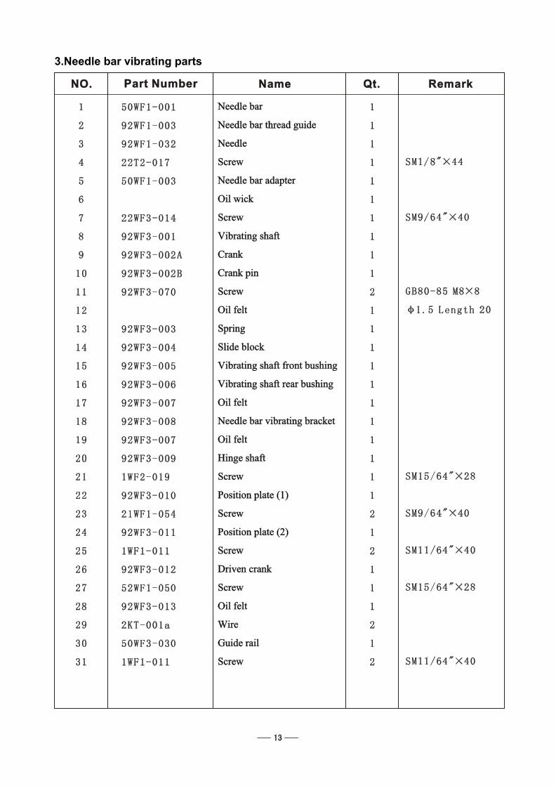
Needle bar
Needle bar thread guide
Needle
Screw
Needle bar adapter
Oil wick
Screw
Vibrating shaft
Crank
Crank pin
Screw
Oil felt
Spring
Slide block
Vibrating shaft front bushing
Vibrating shaft rear bushing
Oil felt
Needle bar vibrating bracket
Oil felt
Hinge shaft
Screw
Position plate (1)
Screw
Position plate (2)
Screw
Driven crank
Screw
Oil felt
Wire
Guide rail
Screw
3.Needle bar vibrating parts
NO.NO. NameName Qt.Qt. RemarkRemarkPart NumberPart Number

4.Upper feed parts

4.Upper feed parts
Connecting barOil feltConnecting pinAdjusting crankScrewScrewWasherNutLifting shaftLifting shaft crankScrewLifting shaft front bushingScrewRubber plugLifting shaft rear bushingOil wickCollarScrewWalking presser footScrewWalking presser foot lifting barSpring guide assemblySpringScrewWalking presser foot lifting linkOil feltSlide blockScrewPresser foot lifting vibrating platePresser foot vibrating linkOil feltWireScrewOil feltWirePresser barPresser bar shaft bushingPresser footRetaining ringScrewScrewNutSpringFeed dog lift leverFeed dog lift lever shaftGuide bracketScrewScrewSlide blockSpacerThread releasing plateSpringScrew
Connecting barOil feltConnecting pinAdjusting crankScrewScrewWasherNutLifting shaftLifting shaft crankScrewLifting shaft front bushingScrewRubber plugLifting shaft rear bushingOil wickCollarScrewWalking presser footScrewWalking presser foot lifting barSpring guide assemblySpringScrewWalking presser foot lifting linkOil feltSlide blockScrewPresser foot lifting vibrating platePresser foot vibrating linkOil feltWireScrewOil feltWirePresser barPresser bar shaft bushingPresser footRetaining ringScrewScrewNutSpringFeed dog lift leverFeed dog lift lever shaftGuide bracketScrewScrewSlide blockSpacerThread releasing plateSpringScrew
NO.NO. NameName Qt.Qt. RemarkRemarkPart NumberPart Number

5.Feed parts

5.Feed parts
Feed linkOil feltLink pinScrewReverse feed tableRetaining plateScrewPresser plateScrewReverse feed table shaftScrewSlide blockFeed vibrating bar assemblyOil wickScrewStitch length adjusting buttonBoltSeal ringScrewStop pinSpringStitch length holderScrewLinkScrewEccentric pinReverse feed lever shaftRetainerReverse feed leverScrewCollarScrewSpringSpring hookScrewFeed shaft bushingScrewFeed shaftCollarScrewCrankScrewLinkScrewNutFeed crankScrewConnecting pinOil wickRetainerFeed dogScrewFeed dog supportScrew
Feed linkOil feltLink pinScrewReverse feed tableRetaining plateScrewPresser plateScrewReverse feed table shaftScrewSlide blockFeed vibrating bar assemblyOil wickScrewStitch length adjusting buttonBoltSeal ringScrewStop pinSpringStitch length holderScrewLinkScrewEccentric pinReverse feed lever shaftRetainerReverse feed leverScrewCollarScrewSpringSpring hookScrewFeed shaft bushingScrewFeed shaftCollarScrewCrankScrewLinkScrewNutFeed crankScrewConnecting pinOil wickRetainerFeed dogScrewFeed dog supportScrew
NO.NO. NameName Qt.Qt. RemarkRemarkPart NumberPart Number

6.Lower shaft and rotating hook shaft

6.Lower shaft and rotating hook shaft
Rotating hook
Bobbin case body
Lower shaft
Lower shaft synchronic wheel assembly
Screw
Lower shaft front bushing
Lower shaft middle bushing
Lower shaft rear bushing
Screw
Lower shaft gear
Screw
Collar
Screw
Rotating hook shaft
Oil wick
Rotating hook front bushing
Screw
Oil felt
Spring
Rotating hook rear bushing
Scrwe
Rotating hook gear
Screw
Collar
Screw
Bobbin
Position hook
Screw
Screw
Nut
Eccentric wheel
Screw
Feed dog lift link
Eccentric pin
Screw
Bearing
Retainer
Cover
Screw
NO.NO. NameName Qt.Qt. RemarkRemarkPart NumberPart Number

7.Thread tension and winding parts

7.Thread tension and winding parts
Thread tension plate assembly
Thread guide plate
Screw
Thread releasing bar
Thread releasing bar bushing
Thread tension disc assembly
Screw
Winder assembly
Washer
Screw
Friction wheel
Screw
Trimming blade
Screw
Thread tension plate assembly
Thread guide plate
Screw
Thread releasing bar
Thread releasing bar bushing
Thread tension disc assembly
Screw
Winder assembly
Washer
Screw
Friction wheel
Screw
Trimming blade
Screw
NO.NO. NameName Qt.Qt. RemarkRemarkPart NumberPart Number

8.Knee control parts

8.Knee control parts
Knee control lever support
Screw
Knee control lever
Screw
Knee control connecting rod
Screw
Screw
Crank
Screw
Knee control revolving shaft
Spring
Position block
Screw
Screw
Nut
Screw
Knee control bell bent bar
Bell bracket
Screw
Knee control bell
Cushion
Screw
Bell bent bar adapter
Knee control connecting bar
Screw
Connecting bushing
Spring
Screw
NO.NO. NameName Qt.Qt. RemarkRemarkPart NumberPart Number

9.Lubrication

9.Lubrication
Oil felt
Oil felt support
Screw
Small oil felt
Wire
Oil wick
Presser plate
Thread Hook
Screw
Oil pot
Oil pot cover
Screw
Oil felt
Oil tube
Oil wick
Oil felt 1
Oil felt 2
Oil retaining plate
Screw
Oilk felt
Oil wick
Oil retaining plate
Screw
Oil wick
Oil felt assembly
Oil felt
Oil felt support
Screw
Small oil felt
Wire
Oil wick
Presser plate
Thread Hook
Screw
Oil pot
Oil pot cover
Screw
Oil felt
Oil tube
Oil wick
Oil felt 1
Oil felt 2
Oil retaining plate
Screw
Oilk felt
Oil wick
Oil retaining plate
Screw
Oil wick
Oil felt assembly
NO.NO. NameName Qt.Qt. RemarkRemarkPart NumberPart Number

10.Accessories

10.Accessories
Safety guard 1
Safety guard 2
Screw
Screw 1
Screw 2
Column
Screw
V-belt
Spool stand
Small oil pot
Parts bag
Spanner
Spanner
Bobbin
Needle
Screwdriver (medium)
Screwdriver (small)
Double ended spanner
Screwdriver (big)
Machine head cover
Oil reservoir
Screw
Oil pot
Adapter
Seal ring
Presser plate
Connecting screw
Spacer
Seal spacer
Connecting nut
Connecting hook assembly
Rubber cushion
Rubber cushion
Oil felt
Screw
NO.NO. NameName Qt.Qt. RemarkRemarkPart NumberPart Number

www.reliablecorporation.com